Embed Size (px)
Citation preview

COURTESY IARE t
LECTURE NOTES ON
BUILDING MATERIALS,CONSTRUCTION PLANNING
Department of Civil Engineering
INSTITUTE OF AERONAUTICAL ENGINEERING (AUTONOMOUS)
Dundigal – 500 043, Hyderabad

COURTESY IARE
UNIT- I: STONES AND BRICKS: Contents
Introduction of Building Stones
Quarrying of Stones Selection of a site for quarrying
Stone quarrying tools
Methods of quarrying
Blasting Materials for blasting
Precautions in blasting
Storage of explosives
Quantity of explosives required
Properties of Building stones
Dressing of a stone
Artificial stones
Forms of Artificial stones
BRICKS characteristics of good brick
Composition / Ingredients of good brick earth
Harmful substances in brick earth
Manufacturing of bricks
Kilns Bull’s Trench Kilns
Intermittent Kilns Continuous Kilns
Tests for bricks Different forms of bricks
1
,

COURTESY IARE t
UNIT- I: STONES AND BRICKS
BUILDING STONES: Man requires different types of buildings such as houses,
bungalows, flats etc for his living. For his activities man also require Hospitals for
his health; Schools, Colleges and Universities for his education; Banks, Shops,
Offices and Factories for doing works; Railway buildings, Bus stations and Air
terminals for his transportation; Clubs and Theatres for recreation and Temples,
Mosques, Churches etc for worship.
Each type of the above buildings has its own requirements and needs building
stones to construct the same. The period from 1750 A D onwards is known as
the period of Modern Architecture.
The use of reinforced concrete in construction triggered the rapid development of
modern architecture. Structural components such as Columns, RCC slabs became increasingly popular
because of the increased speed in construction. Use of plywood, glass, decorative materials etc helped the
designers to make the new structures look more elegant in addition to the usage of various building
stones. So, the engineering structures are composed of materials and are known as the engineering materials ( or )
building materials. Hence, Building materials have an important role to play in this modern age of
technology. Building stones are obtained from rocks, are derived into three groups viz., Igneous,
Sedimentary and Metamorphic rocks. QUARRYING OF STONES: The process of taking out stones from exposed surface of natural rock beds
is known as the quarrying. While selecting a quarry site, one should remember that the availability of
quantity; desired quality, transportation facilities, cheap local labour, and free from the permanent
structures in the vicinity , drainage of rainwater etc.. In case of a quarry, the operations are carried out at ground level (in an exposed condition) whereas in
case of mine, the operations are carried out under the ground at greater depths. SELECTION OF A SITE FOR QUARRYING:
• Availability of Raw material, Tools, Power, Labour • Space for dumping of refuse material. • Distance of quarry from roads, railways.. • Proximity to the transportation facilities. • Easy availability of clean water in sufficient quantity throughout the year. • Economy in quarrying • Blasting material availability • Absence of permanent structures • Geological data regarding rock formations.
1

COURTESY IARE
STONE QUARRYING TOOLS
Tamping Bar: A tamping bar has a small
blade at one end for loosening compacted or
rocky soil and a flattened end for tamping..
Shovels: Shovels are available in various
shapes and handle lengths. shovels are most
common for trail work and are used to move
loosened soil, to dig trenches. They can also
be used for cleaning of culvert outlets.
Post Hole Digger: Used for removing soil
from holes. Soil should be lifted from the
holes. Sledge hammer: A sledgehammer with a 6 to 8
pound head and a 3 foot-long handle is most
useful for trail work. It can be used to crush rock
into gravel. Single Jack Hammer: A single jack (3 to 4
pound head with short handle) hammer can be
used with a star drill to punch holes in rock.
1
COURTESY IARE
Star Drill: Star drills are usually about a foot long
and weigh a pound. They are used with single jack
hammers to punch holes in rock
The plug & feather method involves drilling a series of round holes in the rock spaced every six inches or
so apart. The typical round hole ranges for 1/2 inch to 1 inch in diameter and 3 to 4 inches deep. These
holes are drilled using either a single bladed plug drill or a star drill. The drill is struck by a hammer. The
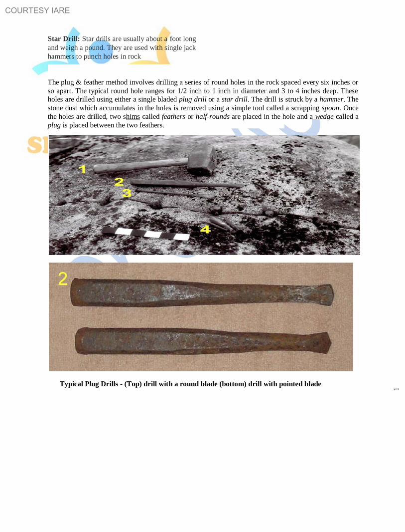
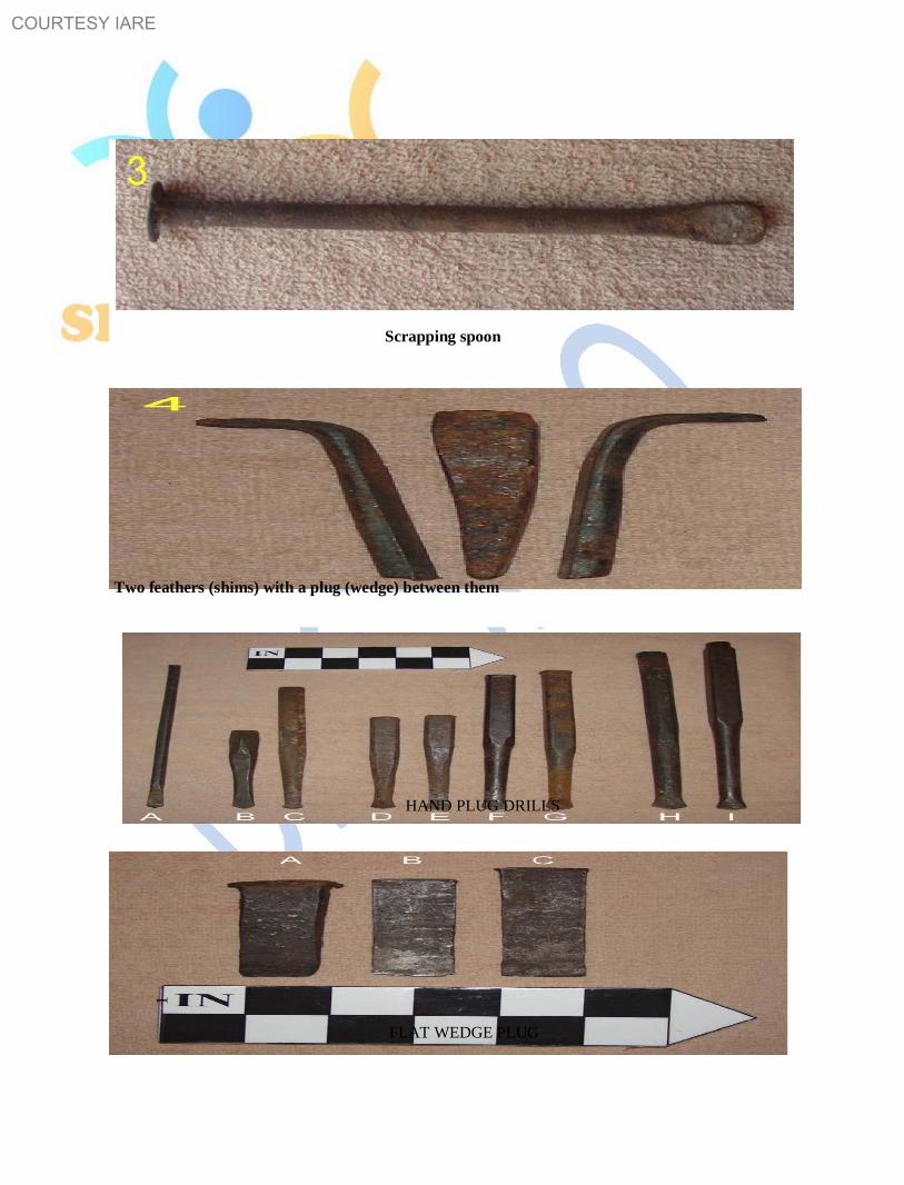
stone dust which accumulates in the holes is removed using a simple tool called a scrapping spoon. Once
the holes are drilled, two shims called feathers or half-rounds are placed in the hole and a wedge called a
plug is placed between the two feathers.
Typical Plug Drills - (Top) drill with a round blade (bottom) drill with pointed blade
1
COURTESY IARE
Scrapping spoon
Two feathers (shims) with a plug (wedge) between them
HAND PLUG DRILLS
1
FLAT WEDGE PLUG

COURTESY IARE
METHODS OF QUARRYING: The purpose of quarrying is to obtain building stones for various
engineering purposes. Depending upon the nature of rocks and the purpose for which stones are needed,
quarrying is done by adopting the following methods: Quarrying is carried out by employing hand tools for digging / excavation, Heating, Wedging and
Blasting. 1. Digging / excavation: In this method, the stones are merely excavated with the help of suitable hand
tools such as Pick axes, Hammers, Spades, Chisels. This method is useful when soft stones occur in the
form of small blocks. 2. Heating: In this method, the surface of rock is heated by placing pieces of wood or by piling a heap of
fuel over the surface and fired for a few hours. Due to unequal expansion, the upper layer of rock
separates out. The detached portion of rock is then removed by suitable hand tools. This method is suitable when the rock formation consists of horizontal layers of shallow depth.
Sometimes, intermediate layers are to be separated from the top and bottom layers. In such a case, the
intermediate layer is heated and the expansion separates it from the other two. 3. Wedging: This method of quarrying is usually adopted for rocks such as Sandstone, Limestone, Marble,
Slate, Laterite etc.. About 10 – 15 cm deep holes, at around 10 cm spacing are made vertically in the rock.
Steel Pins and Wedges or Plugs are inserted in them. These plugs are then struck simultaneously with
sledge hammer. The rock splits along the lines of least resistance through the holes.
4.Blasting: In this method, the explosives are used to convert rocks into small
pieces of stones and the main purpose of quarrying stones by blasting is to loosen large masses of rocks. Explosives such as Gun powder (Blasting powder), Dynamite, (Gelatin),
Detonators, Fuse coil etc. are used. The blasting powder and dynamite are commonly used as the explosives. The blasting powder is also
known as the Gun Powder which is a mixture of charcoal, salt petre (KNO3) and sulphur. Fuses: It is required to ignite the explosives. It is in the form of a small rope of cotton coated with tar and
with a core of continuous thread of fine gun powder. The rate of burning of a good fuse is about 10 mm
per second. Gun cotton: The clean cotton is saturated in a mixture of nitric acid and sulphuric acid. It is pressed into
blocks or sticks while it is wet. It is as strong as dynamite. But its shattering power is less. Liquid Oxygen: It is oxygen in liquid state. It is stored in a special container. It is comparatively cheap and
used for blasting on a large scale for mining operations.
1

COURTESY IARE UNIT-1 1
COMPARISION OF BLASTING POWDER AND DYNAMITE
Item Blasting Powder Dynamite
Action in quarrying Large blocks of stones Small blocks of stones are
are obtained obtained
Cost Cheap High cost and is about 5 times than
that of blasting powder
Destructive power weak Very strong and 6 times than that of
blasting powder.
Efficiency 0.40 m3 0.60 m
3
Use Used for ordinary type Used for tunneling and mining
of quarrying work operations
PRECAUTIONS IN BLASTING:
• Blasting should not be carried out in late evening or early morning hours • A siren should warn the work men and nearby public to maintain a safe distance.
• The danger zone, an area of about 200 mts radius should be marked with
red flags.
• First aid should be available
• The number of charges exploded and the misfires should be recorded
• Explosives should be stored and handled carefully.
• Detonators and explosives should not be kept together
STORAGE OF EXPLOSIVES:
• The explosives should be stored in a magazine which should be away
from residential areas, petrol depots.
• The magazine should have ventilators at high levels and should have concealed wiring. • Magazine should be protected from lightning. • Smoke or fire should not be allowed in the nearby area. • Explosives should be protected from extreme heat or cold and also from moisture. • The magazine should be surrounded by a barbed wire and the entry should be restricted.
1
BMCP NOTES
UNIT-1

COURTESY IARE UNIT-1 1
PROPERTIES OF BUILDING STONES: Various properties such as Porosity,
Permeability, Crushing Strength, Appearance, Durability; Co-efficient of Hardness; Specific gravity; Texture; Toughness Index; Water Absorption; Weathering; Density; Bulk Density;
Density Index; Temperature Resistance etc., are to be properly studied before making final selection of
any building material for a particular use.
Porosity (α ): In simple terms, porosity may be described as the amount of openings ( or ) interstices ( or )
empty spaces present in a rock. However, Porosity may be defined as “the ratio of openings or pores or
voids ( Vi ) in the soil/rock to the total volume of the soil / rock ( V ) expressed as percentage”. If α is the
porosity, then α = Vi / V where Vi is the volume of inters tices and V is the total volume. The average
porosity values for some common geological formations are as follows:
Rock Porosity Rock Porosity
Granite, Quartzite 1.5 % Only Gravel 25 %
Shale, Slate 4 % Only Sand 35 %
Limestone 5-10 % Only Clay 45 %
Sand with gravel 20-30%
Permeability : The permeability of a rock or soil defines its ability to transmit a fluid or water .
Permeability depends on the porosity and interconnected pores character of the rock, thus more porous
rocks are more permeable too. (not always). Permeability in a rock is measured in darcies ( 1 darcy =
0.987 µ m2 square micrometer ).
• Eg: 1.Shales are highly porous but less permeable because of fine grained nature which does not
allow water to pass through the rock due to less interconnected pores. • Eg: 2. Vesicular basalts are highly porous but less permeable because the vesicles in them are not
interconnected (i.e., the effective porosity is less).
Crushing Strength: For a good stone, the crushing strength should be greater than 100 Newton’s / mm2 .
The approximate value of crushing strength of some of the stones are:
S No Rock type Building Stone Crushing Strength ( N/mm2)
1 Igneous Basalt 150 – 185
2 Diorite 90 – 150
3 Granite 75 – 127
4 Syenite 90 – 150
5 Sedimentary Limestone 54
6 Sandstone 64
7 Shale 0.20 – 0.60
8 Metamorphic Gneiss 206 – 370
9 Slate 75 - 207
1
BMCP NOTES
UNIT-1

COURTESY IARE UNIT-1 1
Appearance: The stones which are to be used for face work should be decent in appearance and capable
of preserving their color uniformly for a long time. It is desirable to prefer light colored stones as
compared to dark coloured stones because there are chances of the latter variety to be attacked easily by
weathering agents.
Durability: A good building stone should be durable. The various factors such as Chemical composition;
Resistance to atmospheric conditions etc… influence the durability of a stone. Following are the
important atmospheric agencies which affect the durability of a stone.
a) Alternate conditions of heat and cold due to differences in temperature
b) Alternate conditions of wetness & dryness due to rain and sunshine
c) Chemical agencies such as dissolved gases in rain (eg: NOx; SOx )
d) Growth of trees and Creepers in the joints between the stones.
e) Wind with high velocity. Co-efficient of Hardness: The co-efficient of hardness, as worked out in hardness test should be greater
than 17 for a stone to be used in road work. If it is between 14 and 17, and < 14, the stone is said to be
medium and poor hardness respectively and such stone should not be used in road works. Specific gravity: For a good building stone, the specific gravity should be greater than 2.7 The heavy varieties of stones with more compact and less
porous can be used for various engineering applications such as dams, weirs,
retaining walls, docks etc.. On the other hand, the lighter varieties of stones are to be used for domes, roof
coverings etc.. Texture: A building stone should have compact, fine crystalline nature, free from cavities, cracks, loose
material, softness etc.. Toughness Index: In impact test, if the value of toughness index comes below
13, the stone is not tough. If it comes between 13 and 19, the stone is said to be moderately tough. If it exceeds 19, the toughness of stone is said to be high.
Water Absorption denotes the ability of the stone/ material to absorb and retain
water. It is expressed as % in weight or of the volume of dry material.
Ww = M1 – M x 100 where= M1 means mass of saturated material (g)
V M means mass of dry material (g)
( mm3)
V means volume of material including the pores
A good stone, the absorption % by weight after 24 hours should not exceed
0.60. If rain water is absorbed by porous stones causing them to crumble
hence, the porous stones are not to be recommended for places subjected to rain, moisture, frost…
BMCP NOTES
1
UNIT-1

COURTESY IARE UNIT-1 1
Weathering: A building stone should be capable of with standing adverse effects of various atmospheric
and external agencies such as rain, frost, wind etc..
Density ( p) is the mass of a unit volume of homogeneous material denoted by: p= M / V ( g/cm3) where
M = mass (g) and V = volume (cm3).
Bulk density ( pb) is the mass of a unit volume of material in its natural state (
with pores / voids ) calculated as pb = M / V ( Kg/m3)
where M = Mass of specimen (Kg) and V = Volume of specimen in its natural
state ( m3). Density & Bulk density of some building materials are as follows:
Material Density ( g/cm3) Bulk density ( Kg/m
3)
Brick 2.5 – 2.8 1600 - 1800
Granite 2.6 – 2.9 2500 - 2700
Portland cement 2.9 – 3.1
Wood 1.5 – 1.6 500 - 60
Steel 7.8 – 7.9 7850
Sand 1450 - 1650 Density Index (po) is the ratio between the bulk density and density ie.Po = pb / p
Density index indicates the degree to which the volume of a material is filled with solid matter. For almost all building materials Po is less than 1.0 because there are no absolutely
dense bodies in nature.
In addition, Percentage wear, resistance to fire, dressing etc are also to be considered for a good building
stone.
DRESSING OF A STONE: The stones, after being quarried, are to be cut into suitable sizes and this
process is known as the dressing of stones. The dressing of stones is carried out for the following
purposes:
• To obtain a definite and regular shape. • To make the transport from quarry easy and economical. • Provides pleasing appearance • To suite to the requirements of stone masonry. • At quarry site, it is possible to get cheap labour for the process of
dressing of stones. • It is possible to sort out stones for different works • The irregular and rough portions of the stones are removed which decrease the weight of stones.
1
BMCP NOTES
UNIT-1

COURTESY IARE UNIT-1 1
Following are the varieties of finishes obtained by the dressing of stones: Dragged (or) Combed finish: In this type of finish, a piece of steel which is similar to a comb is rubbed on
the surface in all directions and surface of the stone. This finish is suitable for soft stones only. Punched finish: On the stone surface, the depressions are made by using a punch. The surface of the stone
takes the form of a series of hollows and ridges. Reticulated finish: This type of finish represents a net – like appearance. A
margin about 20 mm wide is marked on the edges of stone and irregular
sinking’s are made on the enclosed space. A pointed tool is used to put the marks on the sunk surface so as to present a pock – marked appearance. Tooled finish: The stone surface is finished by means of a chisel and parallel continuous marks either
horizontal or inclined or vertical are left on the surface. Rock faced finish: Some stones, as obtained from the quarry, possess smooth surface and they can be
directly placed on the work. Such a stone surface is termed as Rock – faced (or) quarry – faced finish. Vermiculated finish: This finish is similar to reticulated type except that the sinking’s are more curved.
ARTIFICIAL STONES: Where durable natural stone is not available at reasonable cost, artificial stone,
also known as CAST STONE becomes the choice. Artificial stone is made with cement and natural
aggregates (crushed stone) and sand with desired surface finish. Suitable color pigments may be added.
Following procedure is generally adopted in making an artificial stone:
• A mixture of 1½ parts of stones of size 3–6 mm; 1½ parts of stones of size < 3mm and 1 part of
cement by volume is prepared. • The necessary pigment is added to produce the desired color effect to the above mixture. • Required quantity of water is added and thorough mixing is done. • The mixture thus prepared is transferred to special moulds. • The mixture is allowed to harden and its surface is kept wet. • The artificial stone is then ready in block form. • Polishing can be done if required.
FORMS OF ARTIFICIAL STONES: Cement Concrete: This is a mixture of cement, fine aggregate, coarse aggregate and water. If steel is used
with cement concrete, it is known as the Reinforced Cement Concrete ( RCC). Concrete blocks are used in
construction of piers, steps, window sills etc…
1

COURTESY IARE UNIT-1 1
Mosaic Tiles: The pre-cast concrete tiles with marble chips at top surface are known as the mosaic tiles. Terrazzo: This is a mixture of marble chips and cement. It is used for bath rooms, residential buildings,
temples etc… Victoria Stones are granite pieces with the surfaces hardened by immersing in soda silicate for about
two months. Ramsom Stones are prepared by mixing soda silicate with cement to provide decorative flooring. These
are also known as chemical stones. These have compressive strength of about 32 N / mm2.
BRICKS
The common brick is one of the oldest building material and it is extensively used at present as a leading
material in construction because of its durability, strength, reliability, low cost, easy availability, easy to
handle etc.. Bricks are used for building up exterior and interior walls, partitions, footings and other load
bearing structures. The Great Wall of China (210 BC) was built with bricks. The other examples of the use of bricks in early
stage of civilization could be in Rome. A number of country farm houses still exist in Great Britain and
profess to be the monuments of the excellent hand – made bricks. A brick is rectangular in shape and of size that can be conveniently handled with one hand. Bricks may be
made of burnt clay or mixture of sand and lime (or) of Portland cement concrete. Size of a standard brick (modular brick) should be 19 x 9 x 9 cm. However, the bricks available in most
part of the country still are 9” x 4 ½” x 3” and are known as field bricks. Weight of such a brick is 3.0 kg. An indent called frog, 1 – 2 cm deep is provided for 9 cm height bricks only. The purpose of
providing frog is to form a key
for holding the mortar and
therefore, the bricks are laid
with frogs on top. Frog is not
provided in 4 cm high bricks.

COURTESY IARE
COMPARISION OF BRICKSTONE AND STONEWORK: The brickwork is superior to the
stonework in the following respects:
• At places where stones are not easily available but where there is plenty
of clay, brickwork becomes cheaper than stonework.
• The cost of construction works out to be less in case of brickwork than
stonework as less skilled labour is required in the construction of brickwork.
• No lifting devices are necessary to carry bricks as they can be easily
moved by manual labour.
• The bricks resist various atmospheric effects better than stones. • In case of brickwork, the mortar joints are thin and hence the structure becomes more durable. • It is easy to construct connections and openings in case of brickwork than stonework.
CHARACTERISTICS OF GOOD BRICK: The essential requirements for building bricks are
sufficient strength in crushing, regularity in size, and a pleasing appearance when exposed to view. Size and shape: The bricks should have uniform in size, rectangular surfaces with parallel sides and sharp
straight edges. Color: The brick should have a uniform deep red (or) cherry colour as indicative of uniformity in
chemical composition and thoroughness in the burning of the brick. Texture and compactness: The surfaces should not be too smooth to cause slipping of mortar. The brick
should have uniform texture and should not show fissures, holes etc.. Hardness and soundness: The brick should be so hard that when scratched by
a finger nail no impression is made. When two bricks are struck together, a
metallic sound should be produced.
Water Absorption should not exceed 20% of its dry weight when kept immersed
in water for 24 hours to 48 hours.
Crushing Strength should not be less than 10 N / mm2.
Brick earth should be free from stones, Kankars, Organic matter, salt petre etc..
COMPOSITION / INGREDIENTS OF GOOD BRICK EARTH: For the preparation
of bricks, clay is usually used. The clay used for brick making consists mainly of
silica and alumina mixed in such a proportion that the clay becomes plastic
when water is added to it. It also consists of small proportions of lime, iron, magnesium, sulphur etc.. The
proportions of various ingredients and functions are as follows:

COURTESY IARE
Silica 50 – 60 %
Alumina 20 – 30 %
Calcium 10 %
Mg < 1 %
Ferric Oxide < 7 % < 20 %
Alkalis < 10 %
SO3; H2O < 2 % Silica: A good brick earth should contain about 50% to 60% of silica. The presence of silica constituent
prevents cracking, shrinking in bricks thus imparts uniform shape to the bricks. Excess of silica makes the
brick brittle and weak on burning. The durability of bricks depends on the proper proportion of silica in
brick earth.
Alumina: A good brick earth should contain about 20 to 30% of alumina. If
alumina is present in excess, with inadequate quantity of sand the raw bricks shrink and it produces cracks during drying and burning and become too hard when burnt. Lime ( calcium ) : A small quantity of lime not exceeding 10% is desirable in good brick earth. The
excess of lime causes the brick to melt and hence its shape is lost and also results in splitting of bricks into
pieces. Magnesia if exceeds 1%, affects the color and makes the brick yellow. Excess of magnesia content leads
to the decay of bricks. Iron – oxide usually constitutes < 7% . If it exceeds 7%, the brick becomes dark blue. When excess of
oxygen is available, the bricks becomes dark brown or black color on burning. HARMFUL SUBSTANCES IN BRICK EARTH: Following are the ingredients which are undesirable
in the brick earth: LIME: When lime is present in lumps, it absorbs moisture, swells and causes disintegration of the bricks. PEBBLES, GRAVELS: The presence of pebbles of any kind is undesirable in brick earth because it will
not allow the clay to be mixed uniformly and thoroughly which will result in weak and porous bricks.
Also the brick containing pebbles will not break regularly as desired. ALKALIES: These are mainly in the form of soda and potash. When alkalies present in excess, the
bricks become unsymmetrical / loose their shape. Further, the presence of excess alkalies content absorb
moisture from the atmosphere. Such moisture, when evaporated, leaves behind grey or white deposits on the wall surface and the
appearance of the building as a whole is then seriously spoiled.
1

COURTESY IARE UNIT-1 1
ORGANIC MATTER: The presence of organic matter in the brick earth, which is not burnt in case, the
bricks become porous and the strength is reduced. SULPHUR & CARBON: Sulphur is usually found in clay as the sulphates of Calcium ( CaSO4);
magnesium (MgSO4); Sodium (NaSO4); Potassium (K2SO4) and iron sulphides ( FeS2). If, however,
there is carbon in the clay and insufficient time is given during burning for proper oxidation of carbon and
sulphur, the latter will cause the formation of a spongy, swollen structure in the brick.
MANUFACTURING OF BRICKS In the process of manufacturing of bricks, the following four distinct operations are involved: 1.
Preparation of clay / Brick earth 2. Moulding
3. Drying 4. Burning
1.PREPARATION OF CLAY / BRICK EARTH consists of the following operations:
a) Un-soiling: The soil used for making building bricks should be processed and to be free from gravel,
sand ( > 2 mm ); lime and kankar particles, organic matter etc. About 200 mm of the top layer of the earth, normally containing stones, pebbles, gravels, plant roots etc is removed after clearing the trees and
vegetation.
b) Digging: The clay is then dug out from the ground and is spread on the
ground. The height of heaps of clay on the ground is about 600 mm to 1200
mm. The digging operation should be done before rains. c)weathering: The clay/soil is left in heaps and exposed to weather for atleast one month. The soil should
be turned over at least twice and it should be ensured that the entire soil is wet throughout the period of
weathering. In order to keep it wet, water may be sprayed as often as necessary. The plasticity and strength of the clay
are improved by exposing the clay to weather. d) Blending: The clay / soil is then mixed with sand and calcareous earth in
suitable proportions to modify the composition of soil uniformly with spades.
Addition of water to the soil at the dumps is necessary for easy mixing and workability. However, the
excessive moisture content may affect the size and shape of the finished brick. The blending makes clay
fit for the next stage of tempering.
e) Tempering: In the process of tempering, the clay is brought to a proper
degree of hardness. The tempering should be done exhaustively to obtain
homogeneous mass of clay of uniform character.
1

COURTESY IARE
For manufacturing good bricks, tempering is done in Pug
Mills and the operation is called Pugging. In other words,
the process of grinding clay with water and making it
plasticity is known as the Pugging
Pug Mill 2.MOULDING: It is a process of giving a required shape to the brick from the prepared clay / soil / brick
earth. Moulding may be carried out by hand or by machines. Hand Moulding: In this process, the bricks are moulded by hand ie manually. It is adopted where man
power is cheap and for producing a small quantity of bricks. A typical wooden mould should be prepared
from well seasoned wood for making bricks. The longer sides are kept slightly projecting to serve as handles. The strips of brass or steel are sometimes
fixed on the edges of wooden moulds to make them more durable. The steel mould even be prepared from steel angles and plates. The thickness of steel mould is generally 6
mm. The bricks prepared by hand moulding are of two types:
(a) Ground - moulded bricks (b) Table – moulded bricks
Ground – Mould bricks: In this process, the ground is leveled and sand is sprinkled on it. The mould is dipped in water and placed over the ground. The clay is pressed or forced in the mould in such a way that it fills all the corners
of the mould. The extra or surplus clay is removed with a sharp edged metal
plate called STRIKE or with a thin wire stretched over the mould.
After this process, the moulded bricks are left on the ground for drying. The
bricks prepared by dipping mould in water every time are known as the slop-
moulded bricks. The fine sand or ash may be sprinkled on the inside surface of mould,, instead of dipping mould in water is known as Sand – Moulded bricks.
COURTESY IARE UNIT-1 1
Table Moulding: the process of moulding these bricks is just similar to ground moulding. But in this
process, the clay, mould, water pots, strikes, pallet boards are placed on the table. A thin board called
pallet is placed over the mould. The bricks are moulded on the table and sent for the further process of
drying. The cost of brick moulding also increases slightly when table moulding is adopted. Machine Moulding: The moulding may also be achieved by machines. It proves to be economical when
bricks in huge quantity are to be manufactured at the same spot in a short time. Machine moulding can be
done by either of the following process:
Plastic method ( Plastic Clay Machine ): The pugged clay is placed in the machine through a rectangular
opening by means of an auger. Clay comes out of the opening in the form of a bar. The bricks are cut from
the bar by a frame consisting of several wires at a distance of brick size and this is a quick and economical
process. This process is also known as WIRE CUT BRICKS. Dry Press Method / Dry Clay Method: In these machines, the strong clay is first converted into powder
form. A small quantity of water is added to form a stiff plastic paste. Such paste is placed in mould and
pressed by machine to form hard and well shaped bricks. These bricks are also known as PRESSED
BRICKS. They can be sent directly for the next process of burning.
3.DRYING: For drying, the bricks are laid longitudinally in stacks. The bricks in stakes should be
arranged in such a way that sufficient air space is left between them. The bricks should be allowed to dry
till they become hard or the moisture content is brought down to about 3% under exposed conditions
within 3 to 4 days.
For the drying purpose, Drying yards should be prepared. The Drying yards should be slightly on a higher
level and it is desirable to cover it with sand. Such an arrangement would prevent the accumulation of rain
water. 4. BURNING: This is a very important operation in the manufacture of bricks. The burning of clay may
be divided into three main stages.
Dehydration stage ( 400 – 650oC): This is also known as water smoking stage. During dehydration :
• The water which has been retained in the pores of the clay after drying is driven off;
• Some of the carbonaceous matter is burnt; • Carbonated minerals are more or less decarbonated; • Too rapid heating causes cracking or bursting of the bricks.
1

COURTESY IARE 1
Oxidation period ( 650 – 900oC): During the oxidation period, the remaining
carbon is eliminated and the ferrous iron is oxidized to the ferric form.
Removal of sulphur is completed only after the carbon has been eliminated.
Vitrification ( upto 1100oC): When the temperature is reached about 1100
oC,
the two important constituents viz., alumina and sand bind themselves together resulting in the increase of strength and density of bricks. If the temperature is raised beyond 1100
oC, a
great amount of fusible glassy mass is formed and the bricks are said to be vitrified. The bricks begin to loose their shape beyond a certain limit of vitrification. Burning of bricks is done in a Clamp or Kiln. A Clamp is a temporary structure whereas Kiln is a permanent one.
Burning in Clamps ( Pazawah): A piece of ground with trapezoidal shape is
selected. The alternate bricks and fuel are placed in layers. The fuel may consist
of grass, cow dung, litter, husks of rice or ground nuts etc.. The thickness of this fuel layer is about 700 – 800 mm. The wood or coal dust may also be used as fuel.
Each brick tier consists of 4 – 5 layers of bricks. The total height of a clamp is
about 3 – 4 mts. When the Clamp is completely constructed, it is plastered with
mud on sides and top and filled with earth to prevent the escape of heat. The
Clamp is allowed to burn for a period of about one to two months and then it
is allowed to cool more or less of the same period as burning. The burnt bricks
are then taken out from the clamp.
CLAMP INTERMITTENT KILN
The production of bricks is 2 – 3 lakhs and the process is completed in 6
months. This process yields about 60% first class bricks.
Kiln burning: A kiln is a large oven which is used to burn bricks. The Kiln
used for burning bricks may be underground ( Bull’s Trench Kiln ) or over ground
( eg: Hoffman’s Kiln). The Kilns may be rectangular, circular or oval in shape. The Kilns are of two types: (i) Intermittent Kilns (ii) Continuous kilns.
INTERMITTENT KILNS: The process of burning bricks is discontinuous and
hence , the kiln is known as intermittent kiln which means that they are loaded,
fired, cooled and unloaded and then the next loading is done. Since the walls
BMCP NOTES
1
UNIT-1
COURTESY IARE UNIT-1 1
and sides get cooled during reloading and are to be heated again during next firing, there is wastage of
fuel. . They may be over ground or underground. Fly ash Bricks: Fly ash bricks are masonry units that are used in the construction of buildings. They are
considered to be a part of good and affordable building materials. They contain Class C fly ash and water. Fly ash bricks are made by compressing Class C fly ash and water at 4000psi and then curing is carried on
for 24 hours at a temperature of 66 degrees Celsius steam bath. Air entrainment agent is used to toughen
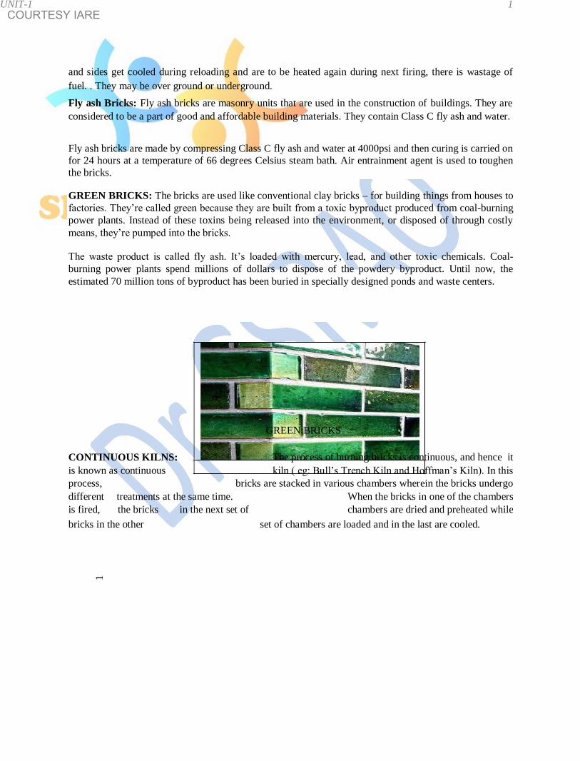
the bricks. GREEN BRICKS: The bricks are used like conventional clay bricks – for building things from houses to
factories. They’re called green because they are built from a toxic byproduct produced from coal-burning
power plants. Instead of these toxins being released into the environment, or disposed of through costly
means, they’re pumped into the bricks.
The waste product is called fly ash. It’s loaded with mercury, lead, and other toxic chemicals. Coal-
burning power plants spend millions of dollars to dispose of the powdery byproduct. Until now, the
estimated 70 million tons of byproduct has been buried in specially designed ponds and waste centers.
GREEN BRICKS
CONTINUOUS KILNS: The process of burning bricks is continuous, and hence it
is known as continuous kiln ( eg: Bull’s Trench Kiln and Hoffman’s Kiln). In this
process, bricks are stacked in various chambers wherein the bricks undergo
different treatments at the same time. When the bricks in one of the chambers
is fired, the bricks in the next set of chambers are dried and preheated while
bricks in the other set of chambers are loaded and in the last are cooled.
1
COURTESY IARE UNIT-1 1
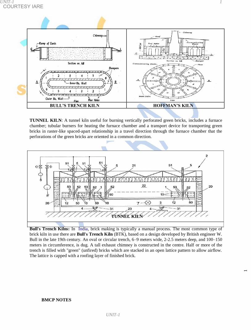
BULL’S TRENCH KILN HOFFMAN’S KILN
TUNNEL KILN: A tunnel kiln useful for burning vertically perforated green bricks, includes a furnace
chamber; tubular burners for heating the furnace chamber and a transport device for transporting green
bricks in raster-like spaced-apart relationship in a travel direction through the furnace chamber that the
perforations of the green bricks are oriented in a common direction.
TUNNEL KILN
Bull's Trench Kilns: In India, brick making is typically a manual process. The most common type of
brick kiln in use there are Bull's Trench Kiln (BTK), based on a design developed by British engineer W.
Bull in the late 19th century. An oval or circular trench, 6–9 meters wide, 2-2.5 meters deep, and 100–150
meters in circumference, is dug. A tall exhaust chimney is constructed in the centre. Half or more of the
trench is filled with "green" (unfired) bricks which are stacked in an open lattice pattern to allow airflow.
The lattice is capped with a roofing layer of finished brick.
1
BMCP NOTES
UNIT-1

COURTESY IARE UNIT-1 1
In operation, new green bricks, along with roofing bricks, are stacked at one end of the brick pile; cooled
finished bricks are removed from the other end for transport. In the middle the brick workers create a
firing zone by dropping fuel (coal, wood, oil, debris, and so on.) through access holes in the roof above
the trench. The advantage of the BTK design is a much greater energy efficiency compared with clamp or scove
kilns. Sheet metal or boards are used to route the airflow through the brick lattice so that fresh air flows
first through the recently burned bricks, heating the air, then through the active burning zone. The air
continues through the green brick zone (pre-heating and drying them), and finally out the chimney where
the rising gases create suction which pulls air through the system. The reuse of heated air yields savings in
fuel cost. A half dozen laborers working around the clock can fire approximately 15,000-25,000 bricks a day. In the
BTK process the bricks do not move. Instead, the locations at which the bricks are loaded, fired, and
unloaded gradually rotate through the trench. TESTS FOR BRICKS: A brick is generally subjected to the following tests to find out its suitability for
the construction work: Water Absorption Test ( US 3495):: A brick is taken and it is weighed dry. It is then immersed in water
for a period of 24 to 48 hours. It is weighed again and the difference in weight indicates the amount of
water absorbed by the brick. It should not, in any case, exceed 5%-20% of weight of dry brick. Compressive Strength Test ( IS: 3495): The crushing strength of a brick is find out by placing in a
compression testing machine. It is pressed till it breaks. The minimum crushing or compressive strength
of bricks is 3.50 N / mm2.
Efflorescence Test: The brick is immersed in water for 24 hours. It is then
taken out and allowed to dry in shade. The absence of grey or white deposits
on its surface indicates the absence of soluble salts. If the white deposits cover about 10% surface, the efflorescence is said to be slight and it is considered as moderate when the white
deposits cover about 50 % of surface. If grey or white deposits are found on more than 50 % of surface,
the efflorescence becomes heavy and it is treated as serious.
Soundness: In this test, the two bricks are taken and they are struck with each
other. The bricks should not break and a clear ringing sound should be
produced.
1
BMCP NOTES
UNIT-1

COURTESY IARE UNIT-1 1
DIFFERENT FORMS OF BRICKS: Various forms of bricks are used depending upon the places of
use. For eg:
Round ended bricks Used to construct open drains
Bull nosed bricks A brick moulded with a rounded
angle. A connection which is
formed when a wall takes a turn is
known as Quoin.
Cant ( splay ) brick Used in case of doors and
windows
Double cant bricks Used for Octagonal pillars
Cornice brick Used for architectural point of
view
Fire / refractory brick It is used in lining furnaces,
kilns, fireboxes, and fireplaces. A
refractory brick is built primarily to
withstand high temperature.
Coping bricks Used for parapets. These bricks
are made to suit the thickness of
walls on which coping is to be
provided.
Perforated bricks The perforated bricks are used
in roadways in order to drain of
the rain water from the streets
Hollow bricks Hollow bricks which are highly used
in construction of houses, buildings
and compound walls.
1
BMCP NOTES

COURTESY IARE
frog providing frog is to form a key for holding the mortar on
the bricks
Gun powder A mixture of charcoal, salt petre (KNO3) and sulphur and
the proportions by weight are 15, 75 and 10 respectively.
Magazine A special type of building meant for storing the explosives.
Masonry Masonry may be defined as the construction of building
units (such as stones, bricks / precast blocks of concrete)
bonded together with mortar.
Metamorphism The process by which the changes are brought in solid
rocks by the agencies of temperature, pressure and
chemical active solutions which in turn establish a new
equilibrium.
Mortar Mortar is a homogeneous mixture produced by uniform
mixing of cement or lime or combination of these two in
addition to sand and water to make a paste of required
consistency.
Pallet A thin board called pallet is placed over the mould
Pugging the process of grinding clay with water and making it
plastic is known as the Pugging.
Strike The extra or surplus clay is removed with a sharp edged
metal plate called STRIKE
Weathering which is a natural process of disintegration and
decomposition 1 1 1

COURTESY IARE
Notes on Building Materials , Construction and Planning for B.Tech (civil ) – II year students
UNIT- 2: CEMENT & ADMIXTURES
Babylonians were perhaps the first to use clay as cementing material. In ancient times stones have
been invariably used as a construction material with lime as
the binder for construction of forts and defense structures. Egyptians have
used lime and gypsum as cementing materials in the famous Pyramids.
The calcareous rocks used by the Romans were either composed of
limestones burned in Kilns or mixtures of limestones and puzzolanic materials
(volcanic ash, tuff) combining into a hard concrete. The natural cement is obtained by burning and crushing the stones containing clay, carbonate of lime
(CaCO3) and a little quantity of magnesia (CaMgCO3)2. The natural cement is
brown in color and is also known as Roman cement.
Pag
e

COURTESY IARE
Ingredient Oxide / % Range Function
composition Lime CaO 62 60 – 65 Controls strength and soundness. Its
deficiency reduces strength & setting time Silica SiO2 22 17 – 25 Imparts strength. Excess cause slow setting Alumina Al2O3 5 3 – 8 Responsible for quick setting, if in excess,
it lowers the strength / weakness the cement Calcium CaSO4 4 3 – 4 A small amount of sulphur is useful in sulphate making sound cement. If it is in excess ,
it causes cement to become unsound. Iron oxide Fe2O3 3 0.5 – 6 Gives colour, hardness & strength to the
cement Magnesia MgO 2 0.5 – 4 Gives color, hardness. If in excess, it
causes cracks in mortar.
Alkalies (Na2O+K2O ) 1 0.1 – 0.4 These are residues and if in excess
cause efflorescence and cracking
USES OF CEMENT: Cement is widely used in construction of various engineering
structures. Following are various possible uses of cement:
• Cement mortar for masonry works
• Cement Concrete for laying floors, roofs, lintels, beams, stairs, pillars etc • Construction of important engineering structures such as Bridges, Culverts, Dams,
Tunnels, storage Reservoirs; Docks etc
• Making Cement Pipes
• Manufacture of precast pipes, dust bins, fencing posts etc..
ORDINARY PORTLAND CEMENT: The artificial cement is obtained by burning
at a very high temperature of a mixture of calcareous ( limestone ) and
argillaceous ( clay ) materials. The calcined product is known as the CLINKER.
A small quantity of gypsum is added to the clinker and it is then pulverized
into very fine powder which is known as the CEMENT. This cement is also
known as the normal setting cement or ordinary cement.
The Ordinary Portland Cement has been classified as 33 Grade ( IS269: 1989);
43 Grade (IS 8112:1989) and 53 Grade (IS 12669:1987). The physical
requirements of all these three types of cement are almost same except for
compressive strength and are as follows:
Grade
S.No Physical requirement 33 43 53
1 Fineness ( m2/Kg) 225 225 225
2 Soundness 10mm 10mm 10mm
3 Setting time ( minimum) 30 minitues 30 30
Pag
e
Setting time ( maximum ) 600 minitues 600 600
4 Compressive Strength (MPa)/n/mm2
72 hours ( 3 days ) 16 23 27
168 hours ( 7 days )
22
33
37
672 hours ( 28 days ) 33 43 53
Dr G
SUBBARAO,
PROFESSOR, NALLA NARASIMHA REDDY GROUP OF
INSTITUTIONS, HYD 1

COURTESY IARE 1 1 1
MANUFACTURE OF CEMENT: Calcareous (limestone, marl, chalk, marine shell) and
argillaceous (clay, shale, slate etc) materials are used in the manufacture of Ordinary or Portland
cement. From these materials, like silica, iron-oxide, and small quantities of other chemicals such as
Na, K, S are obtained during the process of manufacturing of cement. Cement can be manufactured
either by dry process or wet process.
DRY PROCESS ( Modern Technology ) : This process is adopted when the
raw materials are quite hard. The raw materials of limestone and clay are first
reduced in size of about 25 mm in crushers. A dry air is then passed over
these materials. These dried materials are then pulverized into fine powder
separately in the ball mills.
Ball mill is a key equipment to grind the
crushed materials, and the ball mill is
widely used in powder-making production
All these materials are stored in hoppers / bins / silos and they are then mixed
in correct proportions.
Hoppers, bins and silos are used in the aggregate, cement,
chemical, mining and wastewater treatment industries for
storing
many bulk materials.
Bins are used for storing smaller volumes of bulk materials.
Hoppers are similar to bins except with an open top. Silos
are
typically designed for storing large volumes and are cylindrical in
shape with a cone. Storage capacities up to 10,000 cubic feet can easily be
Fig: Hoppers /
Silos
Bins handled with hoppers, bins and silos.
The product obtained after calcination at a temperature of about 1400 – 1500o C
in rotary kiln is called CLINKER.
The clinker is cooled rapidly to preserve the metastable compounds and then ground in Tube Mills
where 2 – 3 % of gypsum is added. The purpose of adding gypsum is to retard the setting of cement.
Generally, cement is stored in bags of 50 kg.
The dry process has been modernized and it is widely used at present because
of competition in production; lesser consumption of power; automatic proper
temperature control ; advancement of instrumentation; computerization and quality.
Pag
e
BMCP NOTES

COURTESY IARE 1 1 1
Flow diagram of manufacturing of cement
WET PROCESS ( old technology ) : Wet process was used for the manufacture
of cement started from 1913 onwards and till early 1980. The operations involved in the wet process of cement manufacture are mixing; burning and grinding.
The crushed raw materials are fed into ball mill and a little water is added
to make a thick paste. This paste, usually contain about 14% of moisture is
dried and made ready for the feed of rotary kiln where it loses moisture and
forms into lumps or nodules.. These are finally burned at 1500 – 1600oC
where the nodules change to clinker at this temperature. Clinker is cooled
and then ground in tube mills. While grinding the clinker, about 3% of
gypsum is added. The cement is then stored in silos from where it is
supplied.
During the operation of ball mill; the steel balls in it pulverize the raw
materials which form a slurry with water. This slurry is passed to silos (storage tanks), where the proportioning of the compounds is adjusted to ensure desired chemical composition.
The chief advantages of the wet process are the low cost of grinding the
raw materials, the accurate control of composition and homogeneity of the
slurry, and the economical utilization of fuel.
BMCP NOTES
Pag
e

COURTESY IARE 1
Physical characteristics of various types of cement
S Type of Soundness by Compressive strength Fineness
no cement Grade (MPa) or N/mm2 (m
2/Kg)
Le Chatelier (mm) Autoclave (%) 3 days 7 days 28 days 225
1 OPC 33 10 0.8 16 22 33 225
2 OPC 43 10 0.8 23 33 43 225
3 OPC 53 10 0.8 27 37 53 225
4 SRC 10 0.8 10 16 33 225
5 PPC 10 0.8 16 22 33 300
6 RHC 10 0.8 27 NS NS 325
7 HAC 5 NS 35 NS NS 225
8 SSC 5 NS 15 22 30 400
9 LHC 10 0.8 10 16 35 320
+NS = NOT SPECIFIED
1-3) OPC = ORDINARY PORTLAND CEMENT
7) HAC = HIGH ALUMINA
CEMENT
4) SRC = SULPHATE RESISTANCE CEMENT
8) SSC = SUPER SULPHATE
CEMENT
5) PPC = PUZZOLONA PORTLAND CEMENT 9) LHC = LOW HEAT CEMENT • RHC = RAPID HARDENING CEMENT Why gypsum is to be added during the manufacture of cement??? The gypsum is the hydrated sulphate of calcium and its chemical composition is CaSO4 2H2O. It
contains 79.1% calcium sulphate and 20.9% water. When gypsum is added to 205oC, its specific
gravity increases from 2.3 to 2.95 due to loss of water. As a binding material, the gypsum quickly sets
and hardens. It is soluble in HCl but insoluble in H2SO4. Gypsum has a number of valuable properties like bulk density, incombustibility, good absorbing
capacity, good fire resistance, rapid drying etc. Because of all these properties, gypsum is used in the
manufacture of cement to increase its setting time. PLASTER OF PARIS: Plaster of Paris is a calcium sulfate hemi-hydrate (CaSO4, ½ H2O) derived
from gypsum by firing this mineral at relatively low temperature of 160
– 170oC and then reducing it to powder. In ancient times, in Paris, all the walls of
wooden houses were covered with plaster as protection against fire. Since then the
plaster was named as Plaster of Paris. POP powder is mixed with water to form a paste which releases heat and then hardens once dried
under normal temperature. Unlike mortar and cement, plaster remains quite soft after drying, and can
be easily rubbed or scratched with metal tools or even sandpaper. On heating, further upto a
temperature of about 20oC, the entire water is driven off and the resulting product is known as the
Gypsum Anhydrite.
Pag
e
BMCP NOTES

COURTESY IARE 1 1 1
FIELD TESTS & LAB TESTS FOR CEMENT: In engineering construction, the main qualifications of a cement are permanency of structure; strength and
a rate of setting. To determine these qualifications, both physical and chemical tests are made, the former on account of importance more often than the other. However,
following field tests are to be carried out to ascertain the quality of cement: • The cement should feel smooth when touched in between fingers. • If it is felt rough, it indicates adulteration with sand. • If hand is inserted in a bag of cement, one should feel cool and not warm. • If a small quantity of cement is thrown in a bucket of water, it should sink and should not float on
the surface. • The color of cement should be uniform and the typical cement color is grey. • The cement should be free from any hard lumps. Such lumps are formed by the absorption of
moisture from the atmosphere. As a result of long experience the physical tests which have come into general use in determining the acceptability of cement are:
• Soundness • Strength: • Consistency Test and • Fineness.
SOUNDNESS: Soundness refers to the ability of a hardened cement paste to retain its volume after
setting without delayed destructive expansion. This destructive expansion is caused by excessive
amount of CaO or MgO. In other words, the purpose of this test is to detect the presence of
uncombined lime in cement. This may happen due to over burning of ingredients of cement in kilns.
So it is an important test to assure the quality of cement since an unsound cement produces cracks,
disintegration and leading to failure finally. Soundness of cement may be tested by Le-Chatelier method or by authoclave method. STRENGTH: Cement is tested for Compressive and Tensile strength because the cement hydrates
when water is added to it. So, the strength of mortar and concrete depends upon the type and nature of
cement. Hydration of cement: The chemi ca l r eact i on bet ween c ement and wat er i s known as hydration
of cement
Pag
e
BMCP NOTES 1

COURTESY IARE 1 1 1
Conditions affecting strength:
• Cement is very strong at early stages if a high lime or high alumina content is present.
• Gypsum and Plaster of Paris in small percentages also tend to increase the strength slightly but
when present in quantities more than 3%, these substances provide variable effects.
• The strength of cement is greatly also influenced by the degree of burning, the fineness of
grinding.
• An under burnt cement is likely to be deficient in strength.
Compressive Strength.: Compressive Strength is the basic data required for mix design. By this test,
the quality and quantity of concrete can be controlled and the degree of adulteration is checked. The compressive strength at the end of 3 days, 7 days and 28 days are given in table and the results are
expressed in N/mm2
Tensile Strength: Tensile Strength may be determined by Briquette Test method or by Split Tensile
Strength Test. The Tensile strength of cement affords quicker indications of defects in the cement. However, the test
is also used for the determination of rapid hardening cement. The tensile strength at the end of 3 days
and 7 days for OPC is 2.0 N / mm2 and 2.5 N/ mm
2 respectively.
( 2.0 N / mm
2 = 20 kg / cm
2 ) ( 2.5 N/ mm
2 = 25 Kg / cm
2 )
Consistency Test: This is a test to estimate the quantity of mixing water to form a paste of normal
consistency.
Vicat apparatus is used to determine the consistency test. 300 gms of
cement is mixed with 25% water. The paste is filled in the mould of
Vicat’s apparatus and the surface of the filled paste is smoothened
and leveled. A square needle 10 mm x 10 mm attached to the plunger
is then lowered gently over the cement paste surface and is released
quickly. The plunger pierces the cement paste. The reading on the
attached scale is recorded. When the reading is 5 – 7 mm from the
bottom of the mould, the amount of water added is considered to be
the correct percentage of water for normal consistency.
Pag
e
BMCP NOTES 1

COURTESY IARE 1 1 1
FINENESS: This test is carried out to check proper grinding of cement. In other words, the degree of
fineness of cement is the measure of the mean size of the grains in it. There are 3 methods for testing fineness:
• The Sieve method -- using 90 micron sieve
• The air permeability method ( Lea Nurse and Blains method )
• The sedimentation method ( Wagner Turbidimetre ) SIEVE METHOD: 100 gms of cement sample is taken and air set lumps if any, in the sample are
broken with fingers. The sample is placed on a 90 micron sieve and continuously sieved for 15
minitues. The residue should not exceed the limits specified below:
OPC 10% of residue by weight
RHC 5% of residue by weight
PPC 5% of residue by weight
Air Permeability method: In this process, a cement sample of 20 mm height is placed in the Lea and
Nurse apparatus and air pressure is applied. A manometer is connected to the top and bottom of the
permeability apparatus and the pressure is so adjusted. The specific surface (Surface area is the measure of how much exposed area a solid object has,
expressed in square units ) for various cements should be as specified in table:
Type Specific
of surface not
cement less than
cm2/gms
OPC 2250
RHC 3250
LHC 3250
PPC 3000
HAC 2250
SSC 4000
Fig: Permeability Apparatus
Pag
e
BMCP NOTES 1

COURTESY IARE 1 1 1
Wagner Turbidimetre method: This method is to be adopted to estimate the surface area of one gram
of cement. The cement is dispersed uniformly in a
rectangular glass tank filled with kerosene. Then, parallel light rays are
passed through the solution which strike the sensitivity plate of a photoelectric cell. The turbidity of the solution at a given instant is measured by taking readings of the
current generated by the cell. By recording the readings at regular intervals while the particles are falling in the solution, it is
possible to secure information regarding the grading in surface area and in size of particle. Readings
are expressed in sq cm per gms.
ADMIXTURES: Admixture is defined as a material, other than water, aggregates, cement, that is
added to the concrete immediately before or during mixing. Admixtures change properties of the
concrete in colour, curing time, temperature range and setting time. Concrete is being used for wide varieties of purposes to make it suitable in different conditions.
Ordinary concrete may fail to exhibit the required quality performance or durability under different
conditions. In such cases, admixture is used to modify the properties of ordinary concrete so as to
make it more suitable for any situation.
Classification of admixtures as given by MR Rixom is:
• Plasticizers ( Water Reducers ) • Superplasticizers ( High Range Water Reducers ) • Retarders • Accelerators • Air entraining Admixtures • Mineral Admixtures / Puzzolanic Admixtures • Chemical Admixtures
Plasticizers and Superplasticizers specifically developed in Japan and Germany around 1950 and later
on they were made popular in USA, Europe and Middle East. Unfortunately, the use of plasticizers
and Superplasticizers have not become popular in India till recently ( 1985). Plasticizers (Water Reducers): Concrete in different situations requires different degree of
workability. A high degree of workability is required in case of beams, columns, beam junctions,
pumping of concrete for considerable distances. One must remember that addition of excess water,
will only improve the fluidity or the consistency but not the workability of concrete.
The easy method generally followed at the site in most of the conditions is
to use extra water to overcome different situations which is unengineering
practice. Today, the use of plasticizers help the difficult conditions for
obtaining higher workability without using excess of water.
BMCP NOTES
Pag
e
1
COURTESY IARE 1 1 1
Superplasticizers (High Range Water Reducers ): Superplasticizers constitute
a relatively new category and improved version of plasticizer, the use of which
was developed in Japan and Germany during 1960 and 1970 respectively. Use of Superplasticizers permit the reduction of water to the extent upto 30% without reducing the
workability. The use of superplasticizer is practiced for the production of high strength and high
performance concrete. Superplasticizers can produce same w/c (water cement ratio); same
workability; increased strength, homogeneous character etc.
Retarders: A retarder is an admixture that slows down the chemical process of hydration so that
concrete remains plasticity and workable for a longer time. The retarders are used in casting purposes.
These are also used in grouting oil wells. Oil wells are sometimes taken upto a depth of about 6000 meter
deep where the temperature may be about 200oC. The spacing between the
steel tube and the wall of the well are to be sealed with cement grout and
to prevent the entry of gas or oil into other rock formations. For all these
works cement grout is required to be in mobile condition for about 3 to 4 hours even at that high
temperature without getting set. Accelerators: These admixtures are added to increase the rate of strength of concrete and to reduce
the required period of curing. In the past one of the commonly used materials as an accelerator was
calcium chloride. The recent studies have shown that calcium chloride is harmful for reinforce
concrete.
Air entraining Admixtures: Air entrained concrete is made by mixing a small quantity of air
entraining agents. These agents modify the properties of concrete regarding workability, segregation,
finishing quality of concrete. Air entraining admixture is used to prevent frost scaling in concrete.
The following types of air entraining agents are used for making concrete:
• Natural wood resins • Animal or vegetable fats and oils such as olive oil, stearic acid; oleic acid. • Various wetting agents such as alkali salts • Miscellaneous materials such as the sodium salts of petroleum sulphonic acids, hydrogen
peroxide and aluminium powder
The common air entraining agents are Vinsol resin, Darex, Airalon, Orvus,
Teepol, Petrosan, Cheecol etc.. Air entrained concrete was used in the
construction of Hirakud dam, Koyna dam, etc. Chemical admixtures: Chemical admixtures are added to concrete in very small amounts mainly for
reduction of water content or control of setting time.
Pag
e
BMCP NOTES 1

COURTESY IARE 1 1 1
Mineral admixtures: Mineral admixtures (puzzolanic materials) are usually added to concrete in
larger amounts to enhance the workability of fresh concrete; to improve resistance of concrete. The term Puzzolana is derived from Pozzuoli, a town in Italy. The sand (volcanic dust) around this
town, when mixed with hydrated lime was found to possess cementious properties. Puzzolanic
materials can be divided into two groups such as: Natural Puzzolanas viz clay, shales, cherts, volcanic tuff which needs further grinding and sometimes
needs calcining to activate them to show puzzolanic properties.
Artificial Puzzolanas include Fly ash, Blast Furnace Slag, Silica fumes.
USES: A proper use of admixtures offers certain beneficial effects to concrete, including improved
quality, acceleration or retardation of setting time, enhanced frost and sulfate resistance, control of
strength development, improved workability, and enhanced finishability. Blast Furnace Slag consisting essentially of silicates and aluminates of calcium. The granulated material when further ground to less than 45 microns will have specific surface of about 400-600 m
2/kg. The chemical composition of BFS is similar to that of cement clinker.

COURTESY IARE 1 1 1 1
Notes on Building Materials , Construction and Planning for B.Tech
(civil ) – II year students
UNIT – VI: FORM WORK (SHUTTERING)
Formwork is the term given to either temporary or permanent moulds into which concrete is poured till it get sufficient strength for self supporting.. The form work involves various materials such as timber (wood), plywood, steel, aluminium, combined wood–steel etc... used as moulds in civil structures, in which concrete is poured. The construction of form work involves considerable
materials. The cost of form work may be upto 20 – 25 % of the cost of
the structure in building works and even higher in bridges. In order to
reduce this expenditure, it is necessary to design economical types of
form work.
When the concrete reach a certain required strength, the form work is no
longer needed and is removed. The operation of removing the form work is commonly known as Stripping. Similarly, when the components of form work are removed and then reused for other parts of the civil structure for several times are known as Panel forms.
FORMWORK MATERIALS:
Timber is the most common material used for form work. When the form work is to be used for small works only a few times, then timber proves to be more economical than steel or aluminium. Advantages: Formwork material of timber is
• easily available
• formwork material can be made to desired shape • can be made to required size • easy to carry
• economically viable and cheap • convenient for small works
Disadvantages:
• possibility of warping, swelling and shrinkage of timber. However, those effects can be overcome by applying shuttering oil as coating. This coating prevents the material from adhering to concrete and hence the stripping (removing of formwork material) makes easier.
1 1

COURTESY IARE 1 1 1
Steel/Aluminium formwork: If the formwork is desired to be re-used several times, then the use of steel or aluminium is preferred. Though the initial cost of steel is very high but for large works with many repetitions, the steel form work proves to be economical. In case of specific structures, such as round columns, curved surfaces, tunnels etc the use of steel form work should be made. Steel form work has many advantages such as
• Can be used a number of times • It provides ease stripping • It ensures an even and smooth concrete surface. • It is not liable to shrinkage/ swelling.
Requirements for a Form work: A good form work should satisfy the following requirements:
• The material of the formwork should be cheap and it should be suitable for re-use several times.
• It should be water proof so that it doesn’t absorb water from concrete. • Shrinkage and swelling of material should be minimum.
• It should be strong enough to withstand all loads coming on it such as dead load of
concrete, live load of concrete during its pouring, compaction and curing of concrete.
• The surface of the form work material should be smooth and should afford easy stripping.
• All joints of the form work should be stiff so that lateral deformation under loads is minimized.
Indian Standards on form work (IS 456 – 2000)
General: The formwork shall confirm to the shape, dimensions etc as shown on the plans and so
constructed as to remain the rigidity during the placing of the concrete and the form work shall be
sufficiently tight to prevent loss of liquid from the concrete.
Cleaning and treatment of forms: All rubbish particularly chippings, saw dust shall be removed
from the interior of the form work material before the concrete is placed.
Procedure to be adopted for removing the form work: All form work materials are to be
removed without creating vibrations as would damage the reinforced concrete. Before the form
work materials are removed, the concrete surface should be checked thoroughly.
Tolerances: Form work shall be so constructed that the internal dimensions are within the permissible tolerance specified by the designer.
1
1

COURTESY IARE 1 1 1
Formwork material (PLYWOOD) modular steel frame work
Reusable plastic form work Steel and plywood formwork
Plywood Column boxes Column boxes
1 1

COURTESY IARE 1 1 1
SCAFFOLDING
The Scaffolding is a temporary frame work of timber or steel components having platforms at different levels, to enable the masons to work at different heights of a buildings. When the height of wall or column or other structure of a building exceeds about 1.5 mts (4’), temporary structures are used to support the platform over which the work men can sit and carry the activities. These temporary structures constructed are very close to the wall, is in the form of timber or steel frame work, commonly called scaffolding. Scaffolding materials is needed for the repairs or even demolition of a building. In addition, surface finishing such as plastering, pointing, white washing or distempering of walls, columns etc at higher levels can also be carried out. The scaffolding should be stable and be strong enough to support work men and other construction material placed on the platform. The height of the scaffolding goes on increasing as the height of construction increases. Components of Scaffolding:
Standards: These are the vertical members of the frame work supported on the ground or embedded into the ground. Ledgers: These are horizontal members, running parallel to the wall, Braces: These are diagonal members fixed on standards.
Putlogs: These are transverse members, placed at right angles to the wall with one end supported on ledgers and other end on the wall. Transoms: These are those putlogs whose both ends are supported on ledgers.
Boardings: These are horizontal platform to support workmen and material and are supported on the putlogs.
Various components or members of the scaffolding are secured by means of rope lashings, nails, bolts etc……
1 1

COURTESY IARE 1 1 1
Standards / verticals Ledgers Braces to standards
Putlogs ( b = putlog hole) Transoms Boarding
Cuplock material Flathead pin Braces
Shoring frame H – frame Adj stirupps
Adjustable base plates Props Cup lock system
1
1

COURTESY IARE 1 1 1
TYPES OF SCAFFODING:
• Single / Bricklayer’s / Putlog scaffolding: It consists of a single row of standards (vertical members) which are driven into the ground. Standards are to be arranged parallel to the wall at distance of 1.20 mts. The standards are then connected to each other by ledgers (horizontal members) placed at right angles. They are secured in position by rope lashings or cuplock materials. The put logs are fastened to ledgers by rope lashings. The cross braces are used for strengthening of the structure.
• Double scaffolding/ Mason’s Scaffolding: This type of scaffolding is stronger than the single scaffolding and is used in the constructions of stone work. The form work is similar to the single scaffolding except two rows of standards are used, one row close to the wall within 15 cm and the other at 1.2 to 1.5 m away from the face of the wall. The put logs are supported at both ends on ledgers. Sometimes, in addition to the diagonal braces, inclined supports called Racking shores are provided to prevent the slipping of scaffold away from the wall.
Single / Bricklayer’s / Putlog Double/Mason’s Double/Mason’s
scaffolding scaffolding (wood) scaffolding (steel)
3. Cantilever Scaffolding / Needle Scaffolding: This type of scaffolding is
needed under the following circumstances:
• Where it is not possible to fix the standards in to the ground
• Where the scaffolding is to be provided on the side of a busy street without obstructing the traffic on road.
• Where the scaffolding is required in case of tall buildings.
In this work, single scaffolding or double scaffolding components are supported by a series of cantilevers or needle beams (timber beams projecting from wall) passing through window openings or through holes in the wall.
1
1

COURTESY IARE 1 1 1
4. Suspended scaffolding: This type of scaffolding is suitable for maintenance works such as painting, pointing, distempering etc. The working platform is suspended from the roofs by means of wire ropes or chains.. The mechanical arrangements are provided to raise or lower the platform to attain the optimum level for working.
Cantilever Scaffolding Cantilever Scaffolding Suspended scaffolding
• Trestle scaffolding: The working platform is supported on the top of mobile devices such as tripods, ladders etc mounted on wheels. Trestle scaffolding is suitable for minor repairs or painting work upto a maximum height of 5 mts from the supporting level.
• Steel scaffolding/Centering: It is practically similar to timber scaffolding except that wooden members are replaced by steel tubes and rope lashings are substituted by special couplings and set-screws at junctions. Though its initial cost is more but its salvage (The property so saved) value is higher.
• Ladder Scaffolding / Patented scaffolding: The working platforms are supported on brackets (with inner row of standards) which can be adjusted at any suitable height. The various components of the scaffold are fastened to each other by means of bolts and screws.
Trestle scaffolding Steel scaffolding Patented scaffolding
1
1

COURTESY IARE 1 1 1
SHORING
The temporary support provided to an unsafe structure or to a structure under-going alterations is
called a shore, and the method of its construction is called shoring. Shoring can be used in case of
• A wall cracks due to unequal settlement and need repairs. • When an adjacent structure is to be dismantled. • When openings are to be made or enlarged in the wall.
• When a wall shows signs of bulging due to improper workmanship which needs
rectification.
Types of shores:
Raking Shores: Rakers of inclined members are used to give lateral support to the wall. Usually a raking shore consists of the following components:
Wall plates
Needles
Cleats
Bracings
Sole plates
Raking shore
The sole plate should be properly embedded into the ground at an inclination and the sole plate
should be accommodating all the rakers and a cleat provided along the outer edge. However the
rakers should be inclined to the ground by 45° to make them move effective.
Flying or Horizontal Shores: These are used to give horizontal support to two adjacent walls in
which the shores do not reach the ground. If the walls are quite near to each other (distance upto 9
mts), single flying shore can be constructed. It consists of wall plates, needles, cleats, struts,
horizontal / flying shore, folding wedges etc…. When the distance between the walls is more, a
composed or double flying shore may be provided.
Flying shores have the advantage that building operations of the ground are not obstructed. Flying
shores are inserted when the old building is being removed, and should be kept in position till the
new unit constructed.
1
1

COURTESY IARE 1 1 1
Dead or Vertical Shores: These consist of vertical members who support the horizontal
members (needles). The horizontal members transfer the load of the wall to the vertical shores
(vertical members). Such vertical shoring is provided to serve the following purposes.
• To rebuild the defective part of the lower portion of the wall; • To deepen the existing foundations. • To make large openings at lower levels.
Holes are made in the wall at suitable heights and the horizontal members, which are made of
thick wooded sections or of steel are inserted in the steel. Each horizontal is supported at its two
ends by vertical ports / dead shores.
The horizontal members are spaced at 1 to 2 mts. A minimum of 3 horizontal shores should be
used for an opening. If the external wall is weak, raking shores may be provided in addition to
vertical shores.
Shores should be removed only when the mew work has gained sufficient strength, but in no case
earlier than 7 days of the completion of new work. An interval of two days should be allowed
between each one of these removal operations.
Flying shore Dead shoring
1
1

COURTESY IARE 1 1 1
UNDER PINNING: The method of supporting a structure, while strengthening its existing foundation to take the increased load is called underpinning. Before under pinning shoring may be done according to the conditions of the structure for its stability. The use of underpinning becomes essential to meet the following requirements under different situations:
• To strengthen the shallow footing of the existing building, when a building with deep
foundation is to be constructed adjoining to it.
• To deepen the existing foundation to increase its bearing capacity so as to sustain heavier loads
• To provide a basement to an existing building structure.
Underpinning can be carried out by the following methods: 5. Pit method ( pit underpinning) 6. Pile Method
Pit method (pit underpinning): In this method, existing wall over the foundation is divided into
various sections, generally 1.2 to 1.5 mt in length. Holes are then made at adequate height in the
existing wall. In these holes, steel needle beams with bearing plates are inserted and supported on
either side of the wall by means of crib supports ( wooden blocks). The jacks in turn are provided
below the wooden blocks.
The pit is now excavated upto the desired level of the proposed new foundation . The old
foundation may be extended upto level of new foundation directly or by cutting the lower part of
old footing as desired.
Pa
ge1
0
1 1
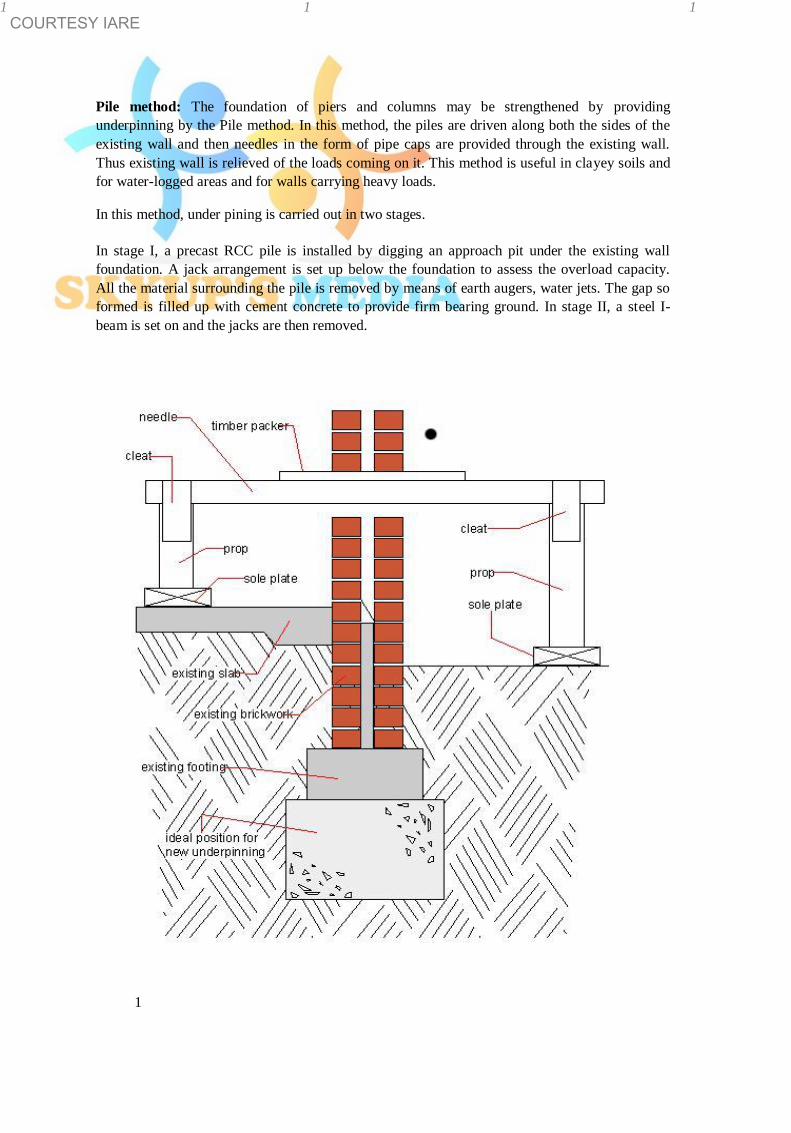
COURTESY IARE 1 1 1
Pile method: The foundation of piers and columns may be strengthened by providing
underpinning by the Pile method. In this method, the piles are driven along both the sides of the
existing wall and then needles in the form of pipe caps are provided through the existing wall.
Thus existing wall is relieved of the loads coming on it. This method is useful in clayey soils and
for water-logged areas and for walls carrying heavy loads.
In this method, under pining is carried out in two stages.
In stage I, a precast RCC pile is installed by digging an approach pit under the existing wall
foundation. A jack arrangement is set up below the foundation to assess the overload capacity.
All the material surrounding the pile is removed by means of earth augers, water jets. The gap so
formed is filled up with cement concrete to provide firm bearing ground. In stage II, a steel I-
beam is set on and the jacks are then removed.
1

COURTESY IARE 1 1 1 1
Notes on Building Materials , Construction and Planning for B.Tech
(civil ) – II year students
UNIT VIII: BUILDING PLANNING
A building consists of a number of rooms including toilets / bath rooms,
kitchen, Hall, bed rooms etc interconnected through corridors, passages
and each room may contain a number of doors, windows, almirahs, cup
boards whereas building drawing reveals the details of all building elements such as foundations, doors, windows, lintels, arches, roofs, floors, sanitary and electrical
fittings. Usually these fittings represent symbolically. The graphical symbols are the shortest
forms of the objects and components. Hence, drawing is the language of Engineers and
Architects.
BUILDING PLANS: A plan is the graphical representation to some scale on
the surface of the earth as projected and represented on the paper on which
the plan is drawn. In order to represent these elements on a plan, the
plan is conventionally prepare at the window sill level (The horizontal member at
the base of a window opening) rather than at the plinth level ( Within the context of construction, it is the top of the foundation walls).
Window sill level Plinth level
The art of arranging various units of a building on all floors and at ground level giving due consideration to planning, drawing; architectural, engineering, finance and
management aspects is known as building planning. Hence, the building planning include
drawing and is the foundation subject for civil engineering students.
1
1

COURTESY IARE 1 1 1
A building may be completely represented by the following types of plans:
Plan of a typical floor: The plan of a typical floor ( ground floor plan at
ground floor level , first floor plan at first floor level) is represented by a
plan cut at the window sill level so that all the windows, cup boards, almirahs etc are also represented on the plan.
Foundation plan: Foundation is immediate beneath the lowest part of the
structure, near to the ground level is known as shallow foundations. Such
foundations are mostly placed on the hard strata available below the ground
level. Shallow foundations are further classified into the following types: 1.Open trench foundations:.
The open-trench foundations were common
whenever the terrain was sufficiently
compact and the trench did not require
much depth. In other situations it was
necessary to reinforce the walls of the
trench to prevent them from collapsing
during digging
2. Grillage foundations: Grillage foundation is used when heavy structural loads from columns,
piers or stanchions are required to be transferred to a soil of low bearing capacity. Grillage
foundation is often found to be lighter and more economical. This avoids deep excavation.
Depending upon the material used in construction of grillage foundation can be broadly divided
in the following two categories. • Steel grillage foundation • Timber grillage foundation
Raft foundations: a foundation (usually on soft ground)
consisting of an extended layer of
reinforced concrete.
Pag
e
1
1

COURTESY IARE 1 1 1
4.Stepped foundations:
A foundation constructed in a series of
steps that approximate
the slope of the bearing stratum.
The purpose is to
avoid horizontal force vectors that might
cause sliding.
5.Inverted arch foundations/ Footing . It is used to be provided for multi-storeyed
buildings in olden times. However, with the
advent of reinforced cement concrete construction practice, inverted arch foooting
is rarely done these days. One of the
drawbacks in this type of construction is that
the end piles have to be specially strengthened by buttresses to avoid the arch
thrust tending to rapture the pier junction.
However, the advantage of inverted arch construction is that in soft soils the depth of
foundation is greatly reduced
Structural plan of a typical floor: A structural plan of a typical floor contains location,
nomenclature and details of various structural elements at that floor level. Terrace plan. The terrace plan is the plan at the roof level showing the stair cabin, lift cabin,
overhead water tanks alongwith roof drainage pattern, parapet walls etc. Classification of buildings: According to National Building code of India 1970, different
classification of buildings on the basis of occupancy are: Group A – Residential Buildings: All those buildings in which sleeping accommodation is
provided for residing permanently or temporarily with or without cooking or dining or both
facilities are termed as residential buildings, for example Apartments, Flats, Bungalows,
Dormitories, Private Houses, Hotels, Hostels, Cottages, Holiday Campus, Clubs, outhouses, Inns, etc., These buildings are further sub-
divided in to 5 groups, namely; A- 1 Lodging Houses; A- 2 Family Private Dwellings; A- 3
Dormitories; A- 4 Flats; and A- 5 Hotels.
1
Pag
e
1

COURTESY IARE 1 1 1
Group B – Educational Buildings: All those buildings which are meant for education from a
nursery to the university, are included in this group, for example, schools, colleges, Universities,
Training Institutes, etc. These buildings provide facilities like class – rooms, staff cabins, drawing
rooms, laboratories, admin blocks, seminar halls; recreation halls, library, playfields, gymnasium
etc.
Group C – Institutional Buildings: This group includes any building which is used for the
purposes such as medical, health, physical or mental disease, care of infants or aged persons, etc.
These buildings normally meant for healthcare for the occupants. These buildings are further sub–divided into three groups viz, C–1 Hospitals; C-2 Custodian
Institutions (a financial institution that has the legal responsibility for a customer's securities) and
C-3 panel Institutions (a group of persons selected for some services).
Group D – Assembly Buildings: This group includes any building where groups of people
assemble or gather for amusement / entertainment. For eg: theatres, cinema halls, assembly halls,
auditoriums, exhibition halls, museums, restaurants, places of worship (temple, mosque, church,
etc.), club rooms, passenger stations, public transportation services; open air theatres, sports
pavilions( i.e., stadium), swimming pools, etc.
Group E – Business Buildings : A commercial building is a building that is used for
commercial use. Types can include office buildings, warehouses, shopping malls, etc
Group F – Mercantile Buildings: This group includes any building or part of a building which
is used as shops, stores, market for sale and display of products or wares either wholesale or
retail.
Group G – Industrial Buildings: This group includes any building in which products of
different kinds and properties, are fabricated, assembled or processed. For example, laboratories,
assembling plants, laundries, gas plants, power plants, refineries, diaries… Group H – Storage Buildings: This group includes to store materials such as cement, iron/steel;
home appliances etc. eg: godowns
Group I – Hazardous Buildings: This group includes those building structures which are used
for the storage, handling, manufacture/ processing of materials which are liable to burn and prove
hazardous to building contents. Hazards may be due to fire, poisonous fumes or gases ,
explosions, ignition, etc., from materials subjected to various operations. Buildings used for
storage of explosive materials, manufacture of synthetic leather, explosives, fire works, etc., .
1
Pag
e
1

COURTESY IARE 1 1 1
BASIC PRINCIPLES OF BUILDING PLANNING: The basic principles of building planning
in respect of residential buildings are:
(1) FLOOR AREA RATIO (FAR) is the ratio of the total covered area of all floors in a building
on a certain plot and to the area of the plot.
The Floor Area Ratio, describes the
relationship between the size of a plot and
the amount of floor space it contains. For
example, a 50' x 100' lot (5,000 sft) with a
single-story 50' x 50' building (2,500 sft)
has a floor area ration of 0.5. If a building
with the same size footprint had 4 stories,
the FAR would increase to 2.
Higher FARs tend to indicate more urban
(dense) construction and is used by local
governments in zoning codes
(2) FLOOR SPACE INDEX ( FSI): It is the ratio of built up area inclusive
of walls of all the floors and to the area of the land on which the building
stands.
Total floor area including walls of all floors Floor Space Index =
Plot Area / Building Unit Thus, an FSI of 2.0 would indicate that the total floor area of a building is two times the gross
area of the plot on which it is constructed, as would be found in a multiple-story building. FSI for
residential buildings in the city area is 4. The value of FSI is fixed by local
authority and it is different for different areas and for different buildings of
the town.
Use Area FSI Remarks
Residential Scheme 1 Only Ground floor is allowed.
Residential City area 4 Facing street of > 12 mts width
Residential City are 3 Facing street of < 12 mts width
(3) ROAD SIDE MARGIN:
Width of Proposed Minimum Road Remarks
Roads (mts.) Side Margin (mts)
Road up to 9mts. and less. 3.00 (1)For the existing built up area
More than 9 mts and upto 12
mts. 4.50 the margins requirement may be
More than 12 mts and upto 18 mts. 6.00
relaxed on merits of individual
More than 18 mts and upto 40
mts. 7.50
case subject to other regulations.
More than 40 mts. 9.00
(2) Minimum side Margin shall be
provided as per regulation no.
12.4.1(A)(ii).
1
Pag
e

COURTESY IARE
1 (4 ) THE AREA OF ROOMS: Bed rooms, living rooms, drawing room, dining room (min) ….9.4 sq mts Kitchen and store rooms (min) 5.45 sq mts Bathrooms and dressing rooms … 1.85 – 4.5 sq mts Water Closet ( WC ); Urinal rooms . 0.89 – 1.1 sq mts
( 5 ) HEIGHT OF ROOF: Roof height on each floor is 2.7 mts ( min ) and for bath room and WC
is 2.1 mts ( min)
(6) AREA OF DOORS, WINDOWS & VENTILATORS: This shall be 1/6
th to 1/10
th of the
floor area of the room. In addition, every room should have ventilator .
(7) STAIR CASE: The stair case shall have area not more than 12 sq mts. The pitch shall be in the range of 30
o to 45
o and flight shall have steps neither < 3 nor > 12.
Minimum width of stair shall be 900 mm.
(8) LIFT: This shall be provided for buildings having more than 3 floors excluding the ground
floor.
(9) SEPTIC TANK: shall be provided as per number of floors / rooms .
(10) HEIGHT OF COMPOUND WALL: The maximum height of compound
wall on road side shall not be more than 1.5 mts and the gates shall
open inwards. On other sides, the height of compound was shall be 1.8
mts.
(11) OPEN SPACE: The open space width shall be 1.8 mts ( min) and 3
mts ( max) for front, rear and sides . (12) PARKING SPACE: Parking spaces for cars required for cinemas, shopping areas and offices
located in central areas are to be allocated as per National Building Code. BUILDING BYE-LAWS: Every locality has its own peculiarities in respect of weather
conditions, availability of material and labour and thus adopts its own method of construction. In
addition, every locality has certain rules and regulations which help in controlling the
development of locality. The rules and regulations covering the requirements and ensure the
safety of the public, minimum use of rooms , area limitations are known as “Building bye-laws”.
1
1

COURTESY IARE 1 1 1
Building bye-laws are necessary to achieve the following objects:
• Gives guidelines to the architects / engineer and thus help in pre-planning the building
activities.
• Allow to prevent haphazard development
• Afford safety against fire, noise pollution, structural failures etc..
While framing building bye-laws assistance of experts on various subjects such as town planning,
law, health, civil engineering, traffic, general administrations etc should be sought due its
weightage.
Indian Standard Institution, an organization of Govt of India has published IS 1256 “code of
building laws” covering all the salient aspect of building activities.. National Building Code (
NBC) was published by the Govt of
India for smooth running of building activities by realizing the importance of
building bye-laws.
EARTHQUAKE RESISTANT BUILDINGS: A sudden movement of the
Earth’s surface often causing a damage is called as Earthquake. So,
Earthquake causes vibrations /motions in ground in random fashion, both
horizontally and vertically and also in all directions radiating from the
epicenter. The intensity and duration of seismic vibrations depends upon
magnitude of the earthquake , its depth of focus, distance from epicenter
etc… It is therefore essential to ensure (i) stability, (ii) strength (iii)
serviceability by means of design of the building.
Earthquake causes shaking of the ground so that a building resting on it
will experience motion at its base and leads to collapse finally due to the
resulting inertia forces. From Newton’s first law of motion even though the base of the building moves with the ground,
the roof has of tendency to stay in its original position. But since the walls and columns are
connected to it, they drag
the roof along with them. This gives rise to inertia forces on the roof
element. .
Structural elements such as floor slabs, walls, columns and foundations
and the connections between them must be designed to safely transfer these inertia forces through them. Walls or columns are the critical elements in transferring the
inertia forces. But , in traditional construction, slabs and beams receive more care and attention
during design and construction than walls and columns. Failure of masonry walls have been
observed because of their thin and materials used for it , in the past due to
1
Pag
e
1

COURTESY IARE 1 1 1
earthquake effect. Hence, importance also is to be given for walls and
columns.
Twist in buildings due to earthquake induces more damage of window
frames and walls. It is best to minimize this twist by ensuring that
buildings have symmetry in plan. Indian Seismic Code ( IS 1893: 2002)
has provisions to come certain issues.
INDIAN SEISMIC CODES for earthquake resistant building: An earthquake
resistant building has the following virtues:
(i)Good structural configuration: Its size, shape and structural system carrying loads are such that
they ensure a direct and smooth flow of inertia forces to the ground.
(ii) Adequate stiffness: Load resistant system is to be followed so that the earthquake induced
deformations in it do not damage under low to moderate shaking.
(iii) Lateral strength : The maximum lateral ( horizontal ) force can resist
the damage induced by an earthquake.
(iv) Good ductility: Favourable design and detailing strategies resist the
building from the earthquakes.
Considerable factors in case of earthquake zones:
Walls transfer loads to each other at their junctions and hence the
masonry courses from the walls meeting at corners must have good
interlocking.
Large openings weaken walls from carrying the inertia forces and it is best
to keep all openings as small as possible and as far away from the
corners as possible.
A variety of masonry units are used in the country eg clay bricks,
concrete blocks, stone blocks. Since bricks are inherently porous and
absorb water resulting in poor bond between brick and mortar. Hence,
bricks with low porosity are to be used to minimize the amount of water
drawn away from the mortar.
Various mortars are used eg mud, cement – sand, cement-sand-lime. Excessive thickness of mortar is not desirable. Indian Standards prescribe the preferred types and
grades of bricks and mortars to be used in buildings in each seismic zone.
1
Pag
e
1

COURTESY IARE
Wall thickness should not exceed 450 mm. Round stone boulders should not be used in the construction.
Since the earthquake force is a function of mass, the building shall be as light as possible.
As far as possible, the parts of the building should be tied together in
such a manner that the building acts as one unit.
Projecting parts shall be avoided as far as possible. If the projecting parts cannot be avoided , they shall be properly reinforced and firmly tied to the main structure and their
design shall be in accordance with IS 1893: 2002.
Buildings having plans with shapes like L – T – E – Y shall preferably be separated into rectangular parts
by providing separation sections at appropriate places.
Structures shall not be founded on loose soils which will subside during an earthquake.
1 1 1
Notes on Building Materials , Construction and Planning for B.Tech (civil ) – II year students
UNIT- 2: CEMENT & ADMIXTURES
Babylonians were perhaps the first to use clay as cementing material. In ancient
times stones have been invariably used as a construction material with lime as the binder for construction of forts and defense structures. Egyptians have
used lime and gypsum as cementing materials in the famous Pyramids.
The calcareous rocks used by the Romans were either composed of
limestones burned in Kilns or mixtures of limestones and puzzolanic materials
(volcanic ash, tuff) combining into a hard concrete. The natural cement is obtained by burning and crushing the stones containing clay, carbonate of lime
(CaCO3) and a little quantity of magnesia (CaMgCO3)2. The natural cement is
brown in color and is also known as Roman cement.
The artificial cement was invented by a mason Joseph Aspdin in England in
1824. He took out a patent for this cement and called it Portland cement
because it had resemblance in its color after setting, to a variety of sandstone which is found in Portland in England. The manufacture of Portland cement was started in England around 1825. Belgium
and Germany started the same in 1855. America started the same in 1872 and India
was installed in Tamil Nadu in 1904. PROPERTIES OF CEMENT:
• It gives strength to the masonry works. • It is an excellent binding material. • It is easily workable • It offers good resistance to the moisture • It possesses a good plasticity. • It hardens early.
COMPOSITION OF ORDINARY CEMENT/ PORTLAND CEMENT: The ordinary
cement contains two basic ingredients namely, argillaceous (clay predominates ) and
calcareous ( calcium carbonate predominates). Excess in quantity of ingredients cause unsound, prolonging of setting time. However, the rate of setting of cement paste is controlled by regulating the ratio SiO2
/ (Al2O3 + Fe2O3). A typical chemical analysis of an ordinary cement is as follows:
BMCP NOTES
Page
1
1 1 1
Notes on Building Materials , Construction and Planning
for B.Tech (civil ) – II year students
UNIT VIII: BUILDING PLANNING
A building consists of a number of rooms including toilets / bath rooms,
kitchen, Hall, bed rooms etc interconnected through corridors, passages
and each room may contain a number of doors, windows, almirahs, cup
boards whereas building drawing reveals the details of all building elements such as foundations, doors, windows, lintels, arches, roofs, floors,
sanitary and electrical fittings. Usually these fittings represent symbolically. The
graphical symbols are the shortest forms of the objects and components. Hence,
drawing is the language of Engineers and Architects.
BUILDING PLANS: A plan is the graphical representation to some scale on the surface of the earth as projected and represented on the paper on which
the plan is drawn. In order to represent these elements on a plan, the
plan is conventionally prepare at the window sill level (The horizontal member at
the base of a window opening) rather than at the plinth level ( Within the context of construction, it is the top of the foundation walls).
Window sill level Plinth level
The art of arranging various units of a building on all floors and at ground level giving due consideration to planning, drawing; architectural, engineering,
finance and management aspects is known as building planning. Hence, the
building planning include drawing and is the foundation subject for civil
engineering students.
1
Page
1