Embed Size (px)
Citation preview
Lecture Notes in Computer Science 4745Commenced Publication in 1973Founding and Former Series Editors:Gerhard Goos, Juris Hartmanis, and Jan van Leeuwen
Editorial Board
David HutchisonLancaster University, UK
Takeo KanadeCarnegie Mellon University, Pittsburgh, PA, USA
Josef KittlerUniversity of Surrey, Guildford, UK
Jon M. KleinbergCornell University, Ithaca, NY, USA
Friedemann MatternETH Zurich, Switzerland
John C. MitchellStanford University, CA, USA
Moni NaorWeizmann Institute of Science, Rehovot, Israel
Oscar NierstraszUniversity of Bern, Switzerland
C. Pandu RanganIndian Institute of Technology, Madras, India
Bernhard SteffenUniversity of Dortmund, Germany
Madhu SudanMassachusetts Institute of Technology, MA, USA
Demetri TerzopoulosUniversity of California, Los Angeles, CA, USA
Doug TygarUniversity of California, Berkeley, CA, USA
Moshe Y. VardiRice University, Houston, TX, USA
Gerhard WeikumMax-Planck Institute of Computer Science, Saarbruecken, Germany
Emmanuel Gaudin Elie Najm Rick Reed (Eds.)
SDL 2007:Design forDependable Systems
13th International SDL ForumParis, France, September 18-21, 2007Proceedings
13

Volume Editors
Emmanuel GaudinPragmaDev SARL18, rue des Tournelles, 75004 Paris, FranceE-mail: [email protected]
Elie NajmENSTDépartement Informatique et Réseaux46, rue Barrault, 75634 Paris Cedex 13, FranceE-mail: [email protected]
Rick ReedTelecommunications Software Engineering LimitedThe Laurels, Victoria Road, Windermere, Cumbria LA23 2DL, United KingdomE-mail: [email protected]
Library of Congress Control Number: 2007934912
CR Subject Classification (1998): C.2, D.2, D.3, F.3, C.3, H.4
LNCS Sublibrary: SL 5 – Computer Communication Networks andTelecommunications
ISSN 0302-9743ISBN-10 3-540-74983-7 Springer Berlin Heidelberg New YorkISBN-13 978-3-540-74983-7 Springer Berlin Heidelberg New York
This work is subject to copyright. All rights are reserved, whether the whole or part of the material isconcerned, specifically the rights of translation, reprinting, re-use of illustrations, recitation, broadcasting,reproduction on microfilms or in any other way, and storage in data banks. Duplication of this publicationor parts thereof is permitted only under the provisions of the German Copyright Law of September 9, 1965,in its current version, and permission for use must always be obtained from Springer. Violations are liableto prosecution under the German Copyright Law.
Springer is a part of Springer Science+Business Media
springer.com
© Springer-Verlag Berlin Heidelberg 2007Printed in Germany
Typesetting: Camera-ready by author, data conversion by Scientific Publishing Services, Chennai, IndiaPrinted on acid-free paper SPIN: 12161393 06/3180 5 4 3 2 1 0
Table of Contents
Model Driven Engineering
A Model-Based Standard for SDL . . . . . . . . . . . . . . . . . . . . . . . . . . . . . . . . . . 1Andreas Prinz, Markus Scheidgen, and Merete S. Tveit
Model Driven Development and Code Generation: An Automotive CaseStudy . . . . . . . . . . . . . . . . . . . . . . . . . . . . . . . . . . . . . . . . . . . . . . . . . . . . . . . . . . 19
Michele Banci, Alessandro Fantechi, Stefania Gnesi, andGiovanni Lombardi
Experiences in Deploying Model-Driven Engineering . . . . . . . . . . . . . . . . . . 35Thomas Weigert, Frank Weil, Kevin Marth, Paul Baker,Clive Jervis, Paul Dietz, Yexuan Gui, Aswin van den Berg,Kim Fleer, David Nelson, Michael Wells, and Brian Mastenbrook
Testing
TTCN-3 Quality Engineering: Using Learning Techniques to EvaluateMetric Sets . . . . . . . . . . . . . . . . . . . . . . . . . . . . . . . . . . . . . . . . . . . . . . . . . . . . . . 54
Edith Werner, Jens Grabowski, Helmut Neukirchen, Nils Rottger,Stephan Waack, and Benjamin Zeiss
Using TTCN for Radio Conformance Test Systems . . . . . . . . . . . . . . . . . . 69Javier Poncela-Gonzalez, Juan Gomez-Salvador,Carlos Valero-Roldan, and Unai Fernandez-Plazaola
Testing UML2.0 Models Using TTCN-3 and the UML2.0 TestingProfile . . . . . . . . . . . . . . . . . . . . . . . . . . . . . . . . . . . . . . . . . . . . . . . . . . . . . . . . . . 86
Paul Baker and Clive Jervis
Language Extensions
Specifying Input Port Bounds in SDL . . . . . . . . . . . . . . . . . . . . . . . . . . . . . . 101Reinhard Gotzhein, Rudiger Grammes, and Thomas Kuhn
Translatable Finite State Time Machine . . . . . . . . . . . . . . . . . . . . . . . . . . . . 117Krzysztof Sacha
Enhanced Use Case Map Traversal Semantics . . . . . . . . . . . . . . . . . . . . . . . . 133Jason Kealey and Daniel Amyot
XII Table of Contents
Implementation
Automated Generation of Micro Protocol Descriptions from SDLDesign Specifications . . . . . . . . . . . . . . . . . . . . . . . . . . . . . . . . . . . . . . . . . . . . . 150
Ingmar Fliege and Reinhard Gotzhein
Synthesizing Components with Sessions from Collaboration-OrientedService Specifications . . . . . . . . . . . . . . . . . . . . . . . . . . . . . . . . . . . . . . . . . . . . . 166
Frank Alexander Kraemer, Rolv Bræk, and Peter Herrmann
Experiences in Using the SOMT Method to Support the Design andImplementation of a Network Simulator . . . . . . . . . . . . . . . . . . . . . . . . . . . . . 186
Manuel Rodrıguez and Jose Marıa Parra
Modeling Experience and Extensions
Consistency of UML/SPT Models . . . . . . . . . . . . . . . . . . . . . . . . . . . . . . . . . . 203Abdelouahed Gherbi and Ferhat Khendek
Formal Verification of Use Case Maps with Real Time Extensions . . . . . . 225Jameleddine Hassine, Juergen Rilling, and Rachida Dssouli
Using Probabilist Models for Studying Realistic Systems: A Case Studyof Pastry . . . . . . . . . . . . . . . . . . . . . . . . . . . . . . . . . . . . . . . . . . . . . . . . . . . . . . . . 242
Guillaume Chatelet, Benoit Parreaux, and Yves-Marie Quemener
OpenComRTOS: An Ultra-Small Network Centric Embedded RTOSDesigned Using Formal Modeling . . . . . . . . . . . . . . . . . . . . . . . . . . . . . . . . . . 258
Eric Verhulst and Gjalt de Jong
SDL Design and Performance Evaluation of a Mobility ManagementTechnique for 3GPP LTE Systems . . . . . . . . . . . . . . . . . . . . . . . . . . . . . . . . . 272
Tae-Hyong Kim, Qi-Ping Yang, Soon-Gi Park, and Yeun-Seung Shin
Author Index . . . . . . . . . . . . . . . . . . . . . . . . . . . . . . . . . . . . . . . . . . . . . . . . . . 289
Using TTCN for Radio Conformance TestSystems
Javier Poncela-Gonzalez, Juan Gomez-Salvador, Carlos Valero-Roldan,and Unai Fernandez-Plazaola
ETSI Telecomunicacion, Campus de Teatinos, s/n,29071 Malaga, Spain
{javier,unai}@ic.uma.es
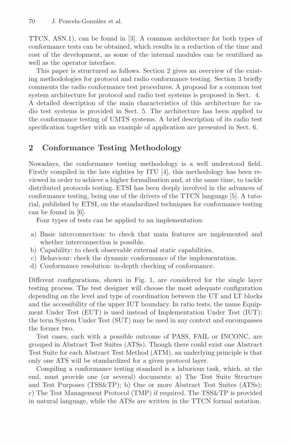
Abstract. While protocol conformance testing methodology is a wellformalized field, radio testing methodology still relies on natural lan-guage specifications. This paper proposes an improvement on the qualityof radio test specifications via the use of formal notation TTCN. Thisapproach, and the fact that protocol and radio conformance testing sharemost of the underlying concepts, enables the use of a generic architecturefor implementations of both types of testers, resulting in a reduction ofthe development efforts. This architecture has been validated with theimplementation of radio test cases for the UMTS technology.
1 Introduction
Since its beginning, the effort in the field of conformance testing has been mainlycentered in the area of protocol testing, where the testing methodology hasattained a high level of formalization [1]. However, radio conformance testinghas not evolved as much further. Radio test specifications are still provided onlyin natural language making them prone to ambiguous interpretations.
Traditionally, the fields of protocol and radio conformance testing have beenconsidered as distant worlds, as the engineering groups related to each of themusually have non-overlapping backgrounds. While the protocol tests are focusedon checking that sequence of messages exchanged between peer entities is per-formed in the correct order and the proper syntax, the aim of the radio tests isto certify the compliance of an implementation in aspects such as transmissionand reception compatibility with other equipment. Nevertheless, most of theconcepts are shared in both areas. For example, the set of documents interna-tionally standardized for testing is nearly the same, as well as the documentationhandled and provided by test laboratories.
In this paper we propose that TTCN is used to model radio test cases whichwould enhance the radio test specifications. Nowadays, these specifications areprovided in natural language. Its quality could be improved by formalizing thetest procedure with the use of TTCN, thus avoiding possible ambiguities andincreasing its consistency [2]. With this approach it is possible to use the samearchitecture for radio and protocol test systems. One example of this architecturefor protocol test systems, implemented using ITU description languages (SDL,
E. Gaudin, E. Najm, and R. Reed (Eds.): SDL 2007, LNCS 4745, pp. 69–85, 2007.c© Springer-Verlag Berlin Heidelberg 2007
70 J. Poncela-Gonzalez et al.
TTCN, ASN.1), can be found in [3]. A common architecture for both types ofconformance tests can be obtained, which results in a reduction of the time andcost of the development, as some of the internal modules can be reutilized aswell as the operator interface.
This paper is structured as follows. Section 2 gives an overview of the exist-ing methodologies for protocol and radio conformance testing. Section 3 brieflycomments the radio conformance test procedures. A proposal for a common testsystem architecture for protocol and radio test systems is proposed in Sect. 4.A detailed description of the main characteristics of this architecture for ra-dio test systems is provided in Sect. 5. The architecture has been applied tothe conformance testing of UMTS systems. A brief description of its radio testspecification together with an example of application are presented in Sect. 6.
2 Conformance Testing Methodology
Nowadays, the conformance testing methodology is a well understood field.Firstly compiled in the late eighties by ITU [4], this methodology has been re-viewed in order to achieve a higher formalization and, at the same time, to tackledistributed protocols testing. ETSI has been deeply involved in the advances ofconformance testing, being one of the drivers of the TTCN language [5]. A tuto-rial, published by ETSI, on the standardized techniques for conformance testingcan be found in [6].
Four types of tests can be applied to an implementation:
a) Basic interconnection: to check that main features are implemented andwhether interconnection is possible.
b) Capability: to check observable external static capabilities.c) Behaviour: check the dynamic conformance of the implementation.d) Conformance resolution: in-depth checking of conformance.
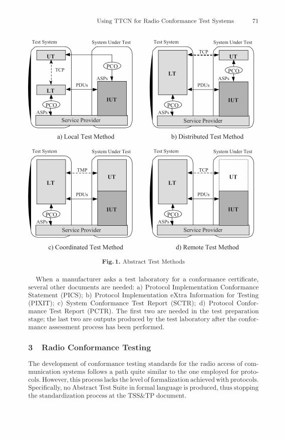
Different configurations, shown in Fig. 1, are considered for the single layertesting process. The test designer will choose the most adequate configurationdepending on the level and type of coordination between the UT and LT blocksand the accessibility of the upper IUT boundary. In ratio tests, the name Equip-ment Under Test (EUT) is used instead of Implementation Under Test (IUT);the term System Under Test (SUT) may be used in any context and encompassesthe former two.
Test cases, each with a possible outcome of PASS, FAIL or INCONC, aregrouped in Abstract Test Suites (ATSs). Though there could exist one AbstractTest Suite for each Abstract Test Method (ATM), an underlying principle is thatonly one ATS will be standardized for a given protocol layer.
Compiling a conformance testing standard is a laborious task, which, at theend, must provide one (or several) documents: a) The Test Suite Structureand Test Purposes (TSS&TP); b) One or more Abstract Test Suites (ATSs);c) The Test Management Protocol (TMP) if required. The TSS&TP is providedin natural language, while the ATSs are written in the TTCN formal notation.
Using TTCN for Radio Conformance Test Systems 71
Service Provider
Test System System Under Test
UT
LT
IUT
ASPs
ASPs
PDUs
TCPPCO
PCO
Service Provider
Test System System Under Test
UT
LT
IUT
ASPs
PDUs
TMP
PCO
Service Provider
Test System System Under Test
UT
LT
IUT
ASPs
ASPs
PDUs
TCP
PCO
PCO
Service Provider
Test System System Under Test
UT
LT
IUT
ASPs
PDUs
TCP
PCO
a) Local Test Method b) Distributed Test Method
c) Coordinated Test Method d) Remote Test Method
Fig. 1. Abstract Test Methods
When a manufacturer asks a test laboratory for a conformance certificate,several other documents are needed: a) Protocol Implementation ConformanceStatement (PICS); b) Protocol Implementation eXtra Information for Testing(PIXIT); c) System Conformance Test Report (SCTR); d) Protocol Confor-mance Test Report (PCTR). The first two are needed in the test preparationstage; the last two are outputs produced by the test laboratory after the confor-mance assessment process has been performed.
3 Radio Conformance Testing
The development of conformance testing standards for the radio access of com-munication systems follows a path quite similar to the one employed for proto-cols. However, this process lacks the level of formalization achieved with protocols.Specifically, no Abstract Test Suite in formal language is produced, thus stoppingthe standardization process at the TSS&TP document.
72 J. Poncela-Gonzalez et al.
A key difference between radio and protocol conformance tests is thatthe former require specific equipment capable of carrying out the needed mea-sures in the air interface. Examples of such instrumentation are wave generators,signal modulators, oscilloscopes, spectrum analyzers, etc. Instruments include in-terfaces to remotely control them, such as RS232, VXI or GPIB. The first oneis an all purpose interface, while the latter has been specifically designed forinstrumentation control, having a higher flexibility and performance. GPIB [7]is characterized by a parallel bus (8 bits) with a bitrate of 8 MB/s1, togetherwith a basic set of high level functions for the equipment management. GPIBcan simultaneously control up to 15 devices at high data rates.
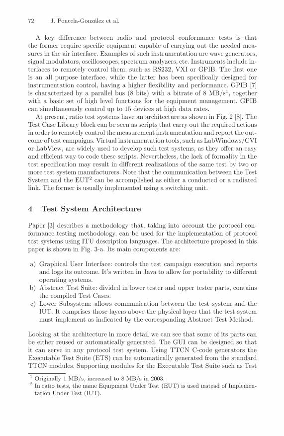
At present, ratio test systems have an architecture as shown in Fig. 2 [8]. TheTest Case Library block can be seen as scripts that carry out the required actionsin order to remotely control the measurement instrumentation and report the out-come of test campaigns. Virtual instrumentation tools, such as LabWindows/CVIor LabView, are widely used to develop such test systems, as they offer an easyand efficient way to code these scripts. Nevertheless, the lack of formality in thetest specification may result in different realizations of the same test by two ormore test system manufacturers. Note that the communication between the TestSystem and the EUT2 can be accomplished as either a conducted or a radiatedlink. The former is usually implemented using a switching unit.
4 Test System Architecture
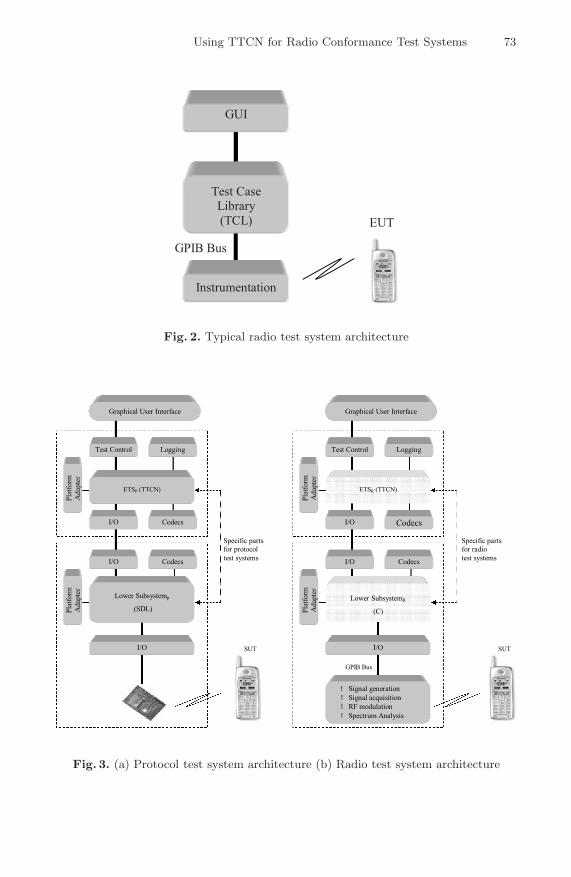
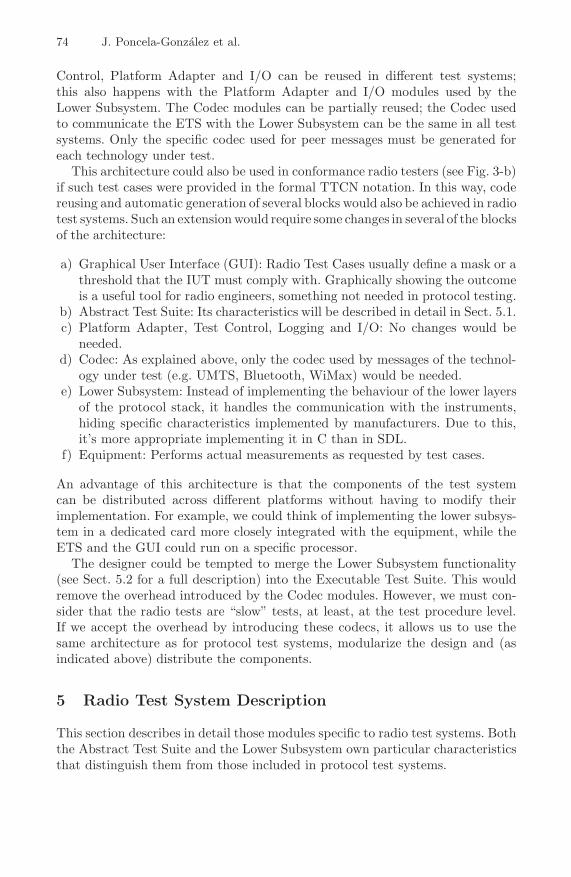
Paper [3] describes a methodology that, taking into account the protocol con-formance testing methodology, can be used for the implementation of protocoltest systems using ITU description languages. The architecture proposed in thispaper is shown in Fig. 3-a. Its main components are:
a) Graphical User Interface: controls the test campaign execution and reportsand logs its outcome. It’s written in Java to allow for portability to differentoperating systems.
b) Abstract Test Suite: divided in lower tester and upper tester parts, containsthe compiled Test Cases.
c) Lower Subsystem: allows communication between the test system and theIUT. It comprises those layers above the physical layer that the test systemmust implement as indicated by the corresponding Abstract Test Method.
Looking at the architecture in more detail we can see that some of its parts canbe either reused or automatically generated. The GUI can be designed so thatit can serve in any protocol test system. Using TTCN C-code generators theExecutable Test Suite (ETS) can be automatically generated from the standardTTCN modules. Supporting modules for the Executable Test Suite such as Test
1 Originally 1 MB/s, increased to 8 MB/s in 2003.2 In ratio tests, the name Equipment Under Test (EUT) is used instead of Implemen-
tation Under Test (IUT).
Using TTCN for Radio Conformance Test Systems 73
GPIB Bus
EUT
GUI
Instrumentation
Test CaseLibrary
(TCL)
Fig. 2. Typical radio test system architecture
Specific partsfor radiotest systems
Lower SubsystemR(C)
ETSR (TTCN)
Codecs
LoggingTest Control
I/O
Platform
Adapter
I/O
I/O
Platform
Adapter
Graphical User Interface
Codecs
Specific partsfor protocoltest systems
Lower Subsystemp(SDL)
SUT
ETSP (TTCN)
Codecs
LoggingTest Control
I/O
Platform
Adapter
I/O
I/O
Platform
Adapter
Graphical User Interface
Codecs
GPIB Bus
SUT
! Signal generation! Signal acquisition! RF modulation! Spectrum Analysis
Fig. 3. (a) Protocol test system architecture (b) Radio test system architecture
74 J. Poncela-Gonzalez et al.
Control, Platform Adapter and I/O can be reused in different test systems;this also happens with the Platform Adapter and I/O modules used by theLower Subsystem. The Codec modules can be partially reused; the Codec usedto communicate the ETS with the Lower Subsystem can be the same in all testsystems. Only the specific codec used for peer messages must be generated foreach technology under test.
This architecture could also be used in conformance radio testers (see Fig. 3-b)if such test cases were provided in the formal TTCN notation. In this way, codereusing and automatic generation of several blocks would also be achieved in radiotest systems. Such an extension would require some changes in several of the blocksof the architecture:
a) Graphical User Interface (GUI): Radio Test Cases usually define a mask or athreshold that the IUT must comply with. Graphically showing the outcomeis a useful tool for radio engineers, something not needed in protocol testing.
b) Abstract Test Suite: Its characteristics will be described in detail in Sect. 5.1.c) Platform Adapter, Test Control, Logging and I/O: No changes would be
needed.d) Codec: As explained above, only the codec used by messages of the technol-
ogy under test (e.g. UMTS, Bluetooth, WiMax) would be needed.e) Lower Subsystem: Instead of implementing the behaviour of the lower layers
of the protocol stack, it handles the communication with the instruments,hiding specific characteristics implemented by manufacturers. Due to this,it’s more appropriate implementing it in C than in SDL.
f) Equipment: Performs actual measurements as requested by test cases.
An advantage of this architecture is that the components of the test systemcan be distributed across different platforms without having to modify theirimplementation. For example, we could think of implementing the lower subsys-tem in a dedicated card more closely integrated with the equipment, while theETS and the GUI could run on a specific processor.
The designer could be tempted to merge the Lower Subsystem functionality(see Sect. 5.2 for a full description) into the Executable Test Suite. This wouldremove the overhead introduced by the Codec modules. However, we must con-sider that the radio tests are “slow” tests, at least, at the test procedure level.If we accept the overhead by introducing these codecs, it allows us to use thesame architecture as for protocol test systems, modularize the design and (asindicated above) distribute the components.
5 Radio Test System Description
This section describes in detail those modules specific to radio test systems. Boththe Abstract Test Suite and the Lower Subsystem own particular characteristicsthat distinguish them from those included in protocol test systems.
Using TTCN for Radio Conformance Test Systems 75
5.1 Abstract Test Suite
The main feature of the proposed architecture for radio test systems is the use ofTTCN. This language would allow the standardization bodies to provide radiotest suites in formal notation, thus leaving out any ambiguity that could arisein the natural language test specifications. At the same time, the validationeffort would be reduced. This section describes the decisions taken and the maincharacteristics of this modelling.
In Sect. 2 the four ATMs defined by the conformance testing methodologyhave been presented. The main difference among these configurations is howthe EUT is controlled during the test execution. There are two options to carryout this control: either automatically configuring the EUT for a test case, ormanually. The first option completely automates the test procedure, but radiotest specifications do not include a Test Controlling Protocol. Because of this,the second option has been chosen. Thus, the remote ATM (see Fig. 1-d) seemsto be the most adequate configuration.
As in protocol tests, radio tests cases can be divided in three different sectionsthat deal with the following duties:
a) Preamble: Sets the instrumentation and puts the EUT into the initial con-ditions demanded by the test case so that the test purpose can be verified.
b) Test body: Carries out the required actions on the EUT and the instrumen-tation in order to check the test purpose
c) Postamble: Although this stage does not explicitly appear in radio test spec-ifications, it is required so that both EUT and instrumentation are put backinto idle state.
The idle state must be defined so that every preamble starts under the sameconditions as there is no fixed order for executing test cases. GPIB instrumen-tation allows two different states: local and remote. The local state, which doesnot allow the remote controlling, has been considered as idle.
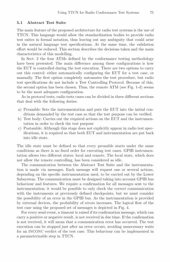
The communication between the Abstract Test Suite and the instrumenta-tion is made via messages. Each message will request one or several actions,depending on the specific instrumentation used, to be carried out by the LowerSubsystem. The communication must be designed taking into account GPIB busbehaviour and features. We require a confirmation for all messages sent to theinstrumentation; it would be possible to only check the correct communicationwith the instruments at previously defined checkpoints, but we must considerthe possibility of an error in the GPIB bus. As the instrumentation is providedby external devices, the probability of errors increases. The logical flow of thetest case using the proposed set of messages is depicted in Fig. 4.
For every send event, a timeout is raised if its confirmation message, which cancarry a positive or negative result, is not received in due time. If the confirmationis not received, it will mean that a communication error has occurred. The testexecution can be stopped just after an error occurs, avoiding unnecessary waitsfor an INCONC verdict of the test case. This behaviour can be implemented ina parameterizable step in TTCN.
76 J. Poncela-Gonzalez et al.
INIT_CONFIG
INIT_BUS
SET_PARAMETER
GET_PARAMETER GET_TRACE
CLOSE_BUS
Configure
Instruments
Initialization
Get Measurement
Configuration
finished?
No
Yes
Additional
Measurements?
No
Set Instruments
to Idle State
Yes
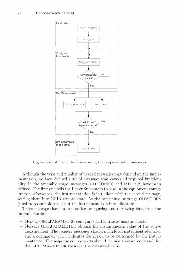
Fig. 4. Logical flow of test cases using the proposed set of messages
Although the type and number of needed messages may depend on the imple-mentation, we have defined a set of messages that covers all required function-ality. In the preamble stage, messages INIT CONFIG and INIT BUS have beendefined. The first one tells the Lower Subsystem to read in the equipment config-uration; afterwards, the instrumentation is initialized with the second message,setting them into GPIB remote state. At the same time, message CLOSE BUS(used in postambles) will put the instrumentation into idle state.
Three messages have been used for configuring and retrieving data from theinstrumentation.
– Message SET PARAMETER configures and activates measurements.– Message GET PARAMETER obtains the instantaneous value of the active
measurement. The request messages should include an instrument identifierand a command, which indicates the action to be performed by the instru-mentation. The response counterparts should include an error code and, forthe GET PARAMETER message, the measured value.
Using TTCN for Radio Conformance Test Systems 77
– The third message is related to one of the functionalities typically needed inradio tests, the capture of a whole trace from an instrument. The points ofthe trace can be obtained either in one shot or by issuing a repetitive seriesof requests. This behaviour should be hidden from the ATS. Consequently,message GET TRACE has been defined. The Lower Subsystem, which knowsthe interface with the instruments, will be responsible for implementing theappropriate actions to read in an entire trace.
Finally, one more message has been used for requesting actions from the operator.This message has been called ACTION REQ and it can carry a text message. Itis handled by the Test Control module.
Radio tests usually require an additional processing after having captureda trace by the instrumentation. This processing may require complex mathe-matical operations. Given that most of these (processing, for example, maxi-mum/minimum search, filtering, bandwidth calculation, demodulation, bit syn-chronization, power integration) are common to radio test suites for differentcommunication systems, we can think of them as a generic signal processinglibrary that can be reused in different test systems, such as GSM, Bluetooth orUMTS. The functions in this library can be called from the TTCN code andlinked at compilation time.
5.2 Lower Subsystem
The Lower Subsystem is the module responsible for the communication betweenthe Abstract Test Suite and the Equipment Under Test. On one hand, it hidesthe physical communication characteristics; on the other hand, it takes intoaccount possible interface differences as instrumentation can be built by differentmanufacturers. The implemented Lower Subsystem offers a generic API that canbe used by any radio test case that is built using GPIB instrumentation.
One first issue is the type of interface offered by the instrumentation for its re-mote control. GPIB [7] has been chosen because of its flexibility and performance.The second issue to tackle is the set of remote commands that can be used. InSect. 5.1 we have shown the messages used in the TTCN test modelling. The LowerSubsystem must map these messages into commands suitable for the specific in-strumentation included in the test system. Several aspects must be considered:
a) The test system must be able to integrate instrumentation from differentmanufacturers.
b) Manufacturers usually only implement a subset of the GPIB standard.c) Proprietary commands are often included to control capabilities that are
specific for the instrument.d) The same command may have different meanings for each device.
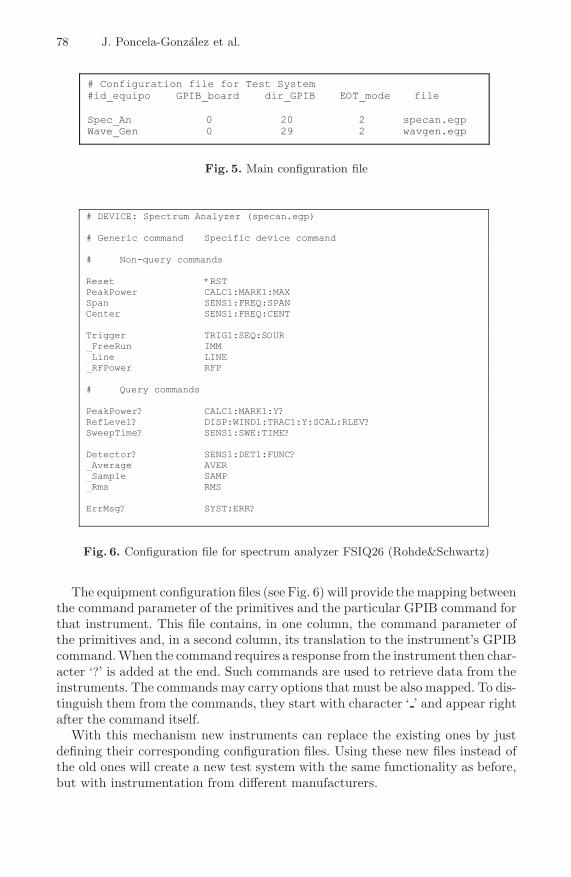
Configuration files can be used to solve these problems. Two types of configu-ration files have been used. The main configuration file (see Fig. 5) contains, foreach instrument, an identifier, specific GPIB information (GPIB card address,GPIB address of the instrument and GPIB signalling mode) and a reference toan equipment configuration file.
78 J. Poncela-Gonzalez et al.
# Configuration file for Test System#id_equipo GPIB_board dir_GPIB EOT_mode file
Spec_An 0 20 2 specan.egpWave_Gen 0 29 2 wavgen.egp
Fig. 5. Main configuration file
# DEVICE: Spectrum Analyzer (specan.egp)
# Generic command Specific device command
# Non-query commands
Reset *RSTPeakPower CALC1:MARK1:MAXSpan SENS1:FREQ:SPANCenter SENS1:FREQ:CENT
Trigger TRIG1:SEQ:SOUR_FreeRun IMM_Line LINE_RFPower RFP
# Query commands
PeakPower? CALC1:MARK1:Y?RefLevel? DISP:WIND1:TRAC1:Y:SCAL:RLEV?SweepTime? SENS1:SWE:TIME?
Detector? SENS1:DET1:FUNC?_Average AVER_Sample SAMP_Rms RMS
ErrMsg? SYST:ERR?
Fig. 6. Configuration file for spectrum analyzer FSIQ26 (Rohde&Schwartz)
The equipment configuration files (see Fig. 6) will provide the mapping betweenthe command parameter of the primitives and the particular GPIB command forthat instrument. This file contains, in one column, the command parameter ofthe primitives and, in a second column, its translation to the instrument’s GPIBcommand. When the command requires a response from the instrument then char-acter ‘?’ is added at the end. Such commands are used to retrieve data from theinstruments. The commands may carry options that must be also mapped. To dis-tinguish them from the commands, they start with character ‘ ’ and appear rightafter the command itself.
With this mechanism new instruments can replace the existing ones by justdefining their corresponding configuration files. Using these new files instead ofthe old ones will create a new test system with the same functionality as before,but with instrumentation from different manufacturers.
Using TTCN for Radio Conformance Test Systems 79
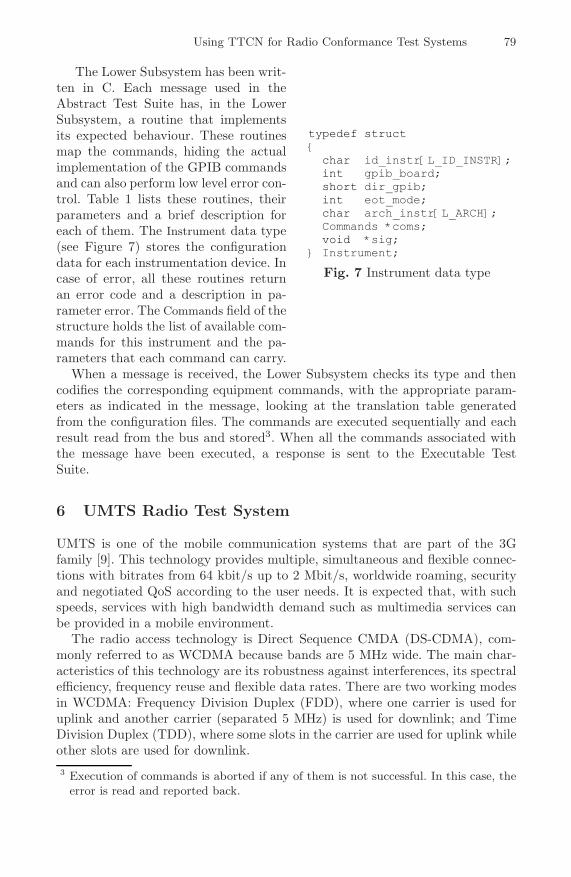
The Lower Subsystem has been writ-ten in C. Each message used in theAbstract Test Suite has, in the LowerSubsystem, a routine that implementsits expected behaviour. These routinesmap the commands, hiding the actualimplementation of the GPIB commandsand can also perform low level error con-trol. Table 1 lists these routines, theirparameters and a brief description foreach of them. The Instrument data type(see Figure 7) stores the configurationdata for each instrumentation device. Incase of error, all these routines returnan error code and a description in pa-rameter error. The Commands field of thestructure holds the list of available com-mands for this instrument and the pa-rameters that each command can carry.
typedef struct
{
char id_instr[L_ID_INSTR];
int gpib_board;
short dir_gpib;
int eot_mode;
char arch_instr[L_ARCH];
Commands *coms;
void *sig;
} Instrument;
Fig. 7 Instrument data type
When a message is received, the Lower Subsystem checks its type and thencodifies the corresponding equipment commands, with the appropriate param-eters as indicated in the message, looking at the translation table generatedfrom the configuration files. The commands are executed sequentially and eachresult read from the bus and stored3. When all the commands associated withthe message have been executed, a response is sent to the Executable TestSuite.
6 UMTS Radio Test System
UMTS is one of the mobile communication systems that are part of the 3Gfamily [9]. This technology provides multiple, simultaneous and flexible connec-tions with bitrates from 64 kbit/s up to 2 Mbit/s, worldwide roaming, securityand negotiated QoS according to the user needs. It is expected that, with suchspeeds, services with high bandwidth demand such as multimedia services canbe provided in a mobile environment.
The radio access technology is Direct Sequence CMDA (DS-CDMA), com-monly referred to as WCDMA because bands are 5 MHz wide. The main char-acteristics of this technology are its robustness against interferences, its spectralefficiency, frequency reuse and flexible data rates. There are two working modesin WCDMA: Frequency Division Duplex (FDD), where one carrier is used foruplink and another carrier (separated 5 MHz) is used for downlink; and TimeDivision Duplex (TDD), where some slots in the carrier are used for uplink whileother slots are used for downlink.
3 Execution of commands is aborted if any of them is not successful. In this case, theerror is read and reported back.
80 J. Poncela-Gonzalez et al.
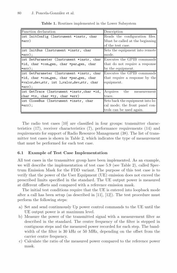
Table 1. Routines implemented in the Lower Subsystem
Function declaration Descriptionint InitConfig (Instrument *instr, char*err)
Reads the configuration files.Must be called at the beginningof the test case.
int InitBus (Instrument *instr, char*err);
Sets the equipment into remotemode.
int SetParameter (Instrument *instr, char*id, char *com gen, char *par gen, char*err);
Executes the GPIB commandsthat do not require a responseby the equipment.
int GetParameter (Instrument *instr, char*id, char *com gen, char *par gen, char*valor dev str, int l valor dev str, char*err);
Executes the GPIB commandsthat require a response by theequipment.
int GetTrace (Instrument *instr,char *id,char *tx, char *ty, char *err)
Acquires the measurementtrace.
int CloseBus (Instrument *instr, char*err);
Sets back the equipment into lo-cal mode; the front panel con-trols can be used again.
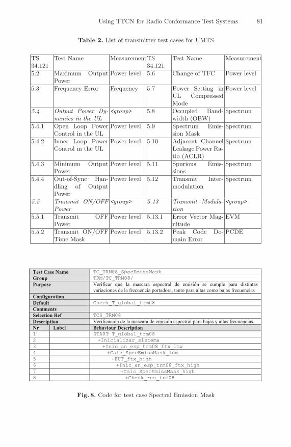
The radio test cases [10] are classified in four groups: transmitter charac-teristics (17), receiver characteristics (7), performance requirements (14) andrequirements for support of Radio Resource Management (38). The list of trans-mitter test cases is shown in Table 2, which indicates the type of measurementthat must be performed for each test case.
6.1 Example of Test Case Implementation
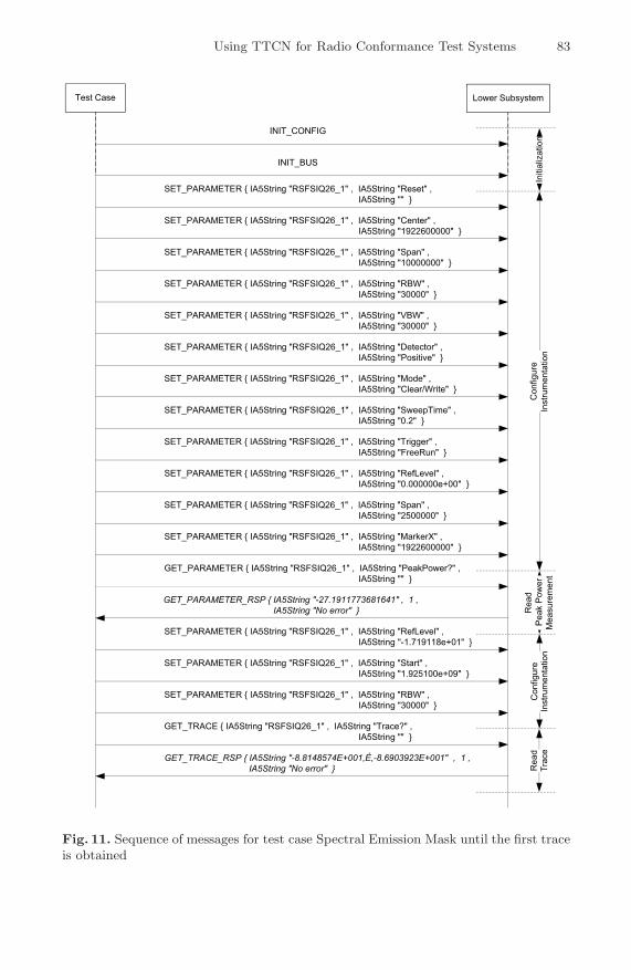
All test cases in the transmitter group have been implemented. As an example,we will describe the implementation of test case 5.9 (see Table 2), called Spec-trum Emission Mask for the FDD variant. The purpose of this test case is toverify that the power of the User Equipment (UE) emission does not exceed theprescribed limits specified in the standard. The UE output power is measuredat different offsets and compared with a reference emission mask.
The initial test conditions require that the UE is entered into loopback modeafter a call has been setup (as described in [11], [12]). The test procedure mustperform the following steps:
a) Set and send continuously Up power control commands to the UE until theUE output power is at maximum level.
b) Measure the power of the transmitted signal with a measurement filter asdescribed in the standard. The centre frequency of the filter is stepped incontiguous steps and the measured power recorded for each step. The band-width of the filter is 30 kHz or 50 MHz, depending on the offset from thecarrier centre frequency.
c) Calculate the ratio of the measured power compared to the reference powermask.
Using TTCN for Radio Conformance Test Systems 81
Table 2. List of transmitter test cases for UMTS
TS34.121
Test Name MeasurementTS34.121
Test Name Measurement
5.2 Maximum OutputPower
Power level 5.6 Change of TFC Power level
5.3 Frequency Error Frequency 5.7 Power Setting inUL CompressedMode
Power level
5.4 Output Power Dy-namics in the UL
<group> 5.8 Occupied Band-width (OBW)
Spectrum
5.4.1 Open Loop PowerControl in the UL
Power level 5.9 Spectrum Emis-sion Mask
Spectrum
5.4.2 Inner Loop PowerControl in the UL
Power level 5.10 Adjacent ChannelLeakage Power Ra-tio (ACLR)
Spectrum
5.4.3 Minimum OutputPower
Power level 5.11 Spurious Emis-sions
Spectrum
5.4.4 Out-of-Sync Han-dling of OutputPower
Power level 5.12 Transmit Inter-modulation
Spectrum
5.5 Transmit ON/OFFPower
<group> 5.13 Transmit Modula-tion
<group>
5.5.1 Transmit OFFPower
Power level 5.13.1 Error Vector Mag-nitude
EVM
5.5.2 Transmit ON/OFFTime Mask
Power level 5.13.2 Peak Code Do-main Error
PCDE
Test Case Name TC_TRM08_SpecEmissMask
Group TRM/TC_TRM08/
Purpose Verificar que la mascara espectral de emisión se cumple para distintas
variaciones de la frecuencia portadora, tanto para altas como bajas frecuencias
Configuration
Default Check_T_global_trm08
Comments
Selection Ref TCS_TRM08
Description Verificación de la mascara de emisión espectral para bajas y altas frecuencias.
Nr Label Behaviour Description
1 START T_global_trm08
2 +Inicializar_sistema
3 +Inic_an_esp_trm08_ftx_low
4 +Calc_SpecEmissMask_low
5 +EUT_ftx_high
6 +Inic_an_esp_trm08_ftx_high
7 +Calc_SpecEmissMask_high
8 +Check_res_trm08
Fig. 8. Code for test case Spectral Emission Mask
82 J. Poncela-Gonzalez et al.
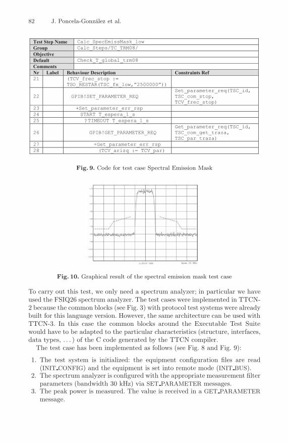
Test Step Name Calc_SpecEmissMask_low
Group Calc_Steps/TC_TRM08/
Objective
Default Check_T_global_trm08
Comments
Nr Label Behaviour Description Constraints Ref
21 (TCV_frec_stop :=TSO_RESTAR(TSC_fx_low,”2500000”))
22 GPIB!SET_PARAMETER_REQSet_parameter_req(TSC_id,TSC_com_stop,TCV_frec_stop)
23 +Set_parameter_err_rsp
24 START T_espera_1_s
25 ?TIMEOUT T_espera_1_s
26 GPIB!GET_PARAMETER_REQGet_parameter_req(TSC_id,TSC_com_get_traza,TSC_par_traza)
27 +Get_parameter_err_rsp
28 (TCV_arizq := TCV_par)
Fig. 9. Code for test case Spectral Emission Mask
Fig. 10. Graphical result of the spectral emission mask test case
To carry out this test, we only need a spectrum analyzer; in particular we haveused the FSIQ26 spectrum analyzer. The test cases were implemented in TTCN-2 because the common blocks (see Fig. 3) with protocol test systems were alreadybuilt for this language version. However, the same architecture can be used withTTCN-3. In this case the common blocks around the Executable Test Suitewould have to be adapted to the particular characteristics (structure, interfaces,data types, . . . ) of the C code generated by the TTCN compiler.
The test case has been implemented as follows (see Fig. 8 and Fig. 9):
1. The test system is initialized: the equipment configuration files are read(INIT CONFIG) and the equipment is set into remote mode (INIT BUS).
2. The spectrum analyzer is configured with the appropriate measurement filterparameters (bandwidth 30 kHz) via SET PARAMETER messages.
3. The peak power is measured. The value is received in a GET PARAMETERmessage.
Using TTCN for Radio Conformance Test Systems 83
INIT_CONFIG
INIT_BUS
SET_PARAMETER { IA5String "RSFSIQ26_1" , IA5String "Reset" ,IA5String "" }
SET_PARAMETER { IA5String "RSFSIQ26_1" , IA5String "Center" ,IA5String "1922600000" }
SET_PARAMETER { IA5String "RSFSIQ26_1" , IA5String "Span" ,IA5String "10000000" }
SET_PARAMETER { IA5String "RSFSIQ26_1" , IA5String "RBW" ,IA5String "30000" }
SET_PARAMETER { IA5String "RSFSIQ26_1" , IA5String "VBW" ,IA5String "30000" }
SET_PARAMETER { IA5String "RSFSIQ26_1" , IA5String "Detector" ,IA5String "Positive" }
SET_PARAMETER { IA5String "RSFSIQ26_1" , IA5String "Mode" ,IA5String "Clear/Write" }
SET_PARAMETER { IA5String "RSFSIQ26_1" , IA5String "SweepTime" ,IA5String "0.2" }
SET_PARAMETER { IA5String "RSFSIQ26_1" , IA5String "Trigger" ,IA5String "FreeRun" }
SET_PARAMETER { IA5String "RSFSIQ26_1" , IA5String "RefLevel" ,IA5String "0.000000e+00" }
SET_PARAMETER { IA5String "RSFSIQ26_1" , IA5String "Span" ,IA5String "2500000" }
SET_PARAMETER { IA5String "RSFSIQ26_1" , IA5String "MarkerX" ,IA5String "1922600000" }
GET_PARAMETER { IA5String "RSFSIQ26_1" , IA5String "PeakPower?" ,IA5String "" }
SET_PARAMETER { IA5String "RSFSIQ26_1" , IA5String "RefLevel" ,IA5String "-1.719118e+01" }
SET_PARAMETER { IA5String "RSFSIQ26_1" , IA5String "Start" ,IA5String "1.925100e+09" }
SET_PARAMETER { IA5String "RSFSIQ26_1" , IA5String "RBW" ,IA5String "30000" }
GET_TRACE { IA5String "RSFSIQ26_1" , IA5String "Trace?" ,IA5String "" }
GET_TRACE_RSP { IA5String "-8.8148574E+001,É,-8.6903923E+001" , 1 ,IA5String "No error" }
GET_PARAMETER_RSP { IA5String "-27.1911773681641" , 1 ,IA5String "No error" }
Test Case Lower Subsystem
Initi
aliz
atio
nC
onfig
ure
Con
figur
eIn
stru
men
tatio
nIn
stru
men
tatio
n
Rea
dR
ead
Trac
eP
eak
Pow
erM
easu
rem
ent
Fig. 11. Sequence of messages for test case Spectral Emission Mask until the first traceis obtained
84 J. Poncela-Gonzalez et al.
4. Measurements for frequencies with offset up to +2.5 MHz from the carrierfrequency are taken (steps of 5 kHz) using the GET TRACE message.
5. Measurements for frequencies with offset down to -2.5 MHz from the carrierfrequency are taken (steps of 5 kHz) as before.
6. The spectrum analyzer is configured for a bandwidth resolution of 50 kHz.7. Measurements for frequencies with offset from -12.5 MHz up to +12.5 MHz
from the carrier frequency are taken (steps of 25 kHz).8. Measurements are compared with the reference emission mask and a verdict
is generated.
When the test finishes a graphical report of the measured results is provided onthe operator screen such as shown in Fig. 10. The dotted line represents the refer-ence power levels. Figure 11 shows the sequence of messages exchanged betweenthe test case and the Lower Subsystem from the beginning of the execution untilthe fourth step, where the first trace is read.
7 Conclusion
A methodology for radio conformance testing has been presented, which increasesthe quality of the radio test specifications as these are currently written in naturallanguage. Using TTCN represents a step forward in the formalization of thesetest specifications. The validation process for test systems is simplified as someof their parts would have already been agreed by the qualification bodies.
The proposed architecture is derived as an extension from one that has pro-vided good results in protocol conformance test systems. Several modules canbe shared between both types of test systems, thus reducing the effort and costrequired for the development.
This architecture enables the integration of instrumentation from differentmanufacturers as well as its straightforward substitution by other instrumenta-tion with equivalent capabilities. This is achieved by the use of GPIB bus forthe communication with the instrumentation and the definition of configurationfiles that particularize the interface implemented by each instrument.
As an example of use, the implementation of one transmitter test case forthe UMTS system has been shown. Additionally, this architecture has also beenused to implement the set of radio test cases for Bluetooth system.
Acknowledgments
This work has been partially funded by AT4 wireless and Spanish government.
References
1. Tretmans, J.: An Overview of OSI Conformance Testing, Formal Methods & Toolsgroup. University of Twente, 2001. Translated and adapted from: Tretmans, J.,van de Lagemaat, J., Conformance Testen. In: Handboek Telematica, vol. II, pages4400, pp. 1–19. Samson (2001)
Using TTCN for Radio Conformance Test Systems 85
2. Kegley, K., Stavridou, V.: The Role of Formal Methods in Software Standards.In: Fourth IEEE International Symposium and Forum on Software EngineeringStandards (1999)
3. Poncela, J., Sanchez, R., Tapia, P., Ferrer, R., Entrambasaguas, J.T.: Testbed De-velopment for Communication Systems using Formal Languages. In: 2nd Workshopon SDL and MSC, Grenoble (June 26-28, 2000)
4. ITU-T X.290-X.296: OSI Conformance Testing Methodology and Framework forProtocol Recommendations for ITU-T Applications (1998)
5. ETSI ES 201 873: Methods for Testing and Specification (MTS): The Testing andTest Control Notation version 3, v 3.2.1 (2007)
6. ETR 021: Advanced Testing Methods (ATM): Tutorial on protocol conformancetesting (1991)
7. IEEE Std. 488.1: IEEE Standard for Higher Performance Protocol for the StandardDigital Interface for Programmable Instrumentation (2003)
8. Banos, J.: Testing of Bluetooth Products in the Industrial Environment, IECON(2002)
9. 3rd Generation Partnership Project: http://www.3gpp.org/specs/specs.htm10. 3GPP TS 34.121: 3rd Generation Partnership Project; Technical Specification
Group Terminals; Terminal Conformance Specification: Radio transmission andreception (FDD)
11. 3GPP TS 34.108: 3rd Generation Partnership Project; Technical SpecificationGroup Terminals; Common Test Environments for User Equipment (UE) Con-formance Testing
12. 3GPP TS 34.108: Universal Mobile Telecommunications System (UMTS): Terminallogical test interface; Special conformance testing functions
Abbreviations
ATS Abstract Test SuiteATM Abstract Test MethodETS Executable Test SuiteEUT Equipment Under TestFDD Frequency Division DuplexGPIB General Purpose Interface BusGUI Graphical User InterfaceIUT Implementation Under TestSUT System Under TestTDD Time Division DuplexUE User EquipmentUMTS Universal Mobile Telecommunications System