Embed Size (px)
Citation preview

LECTURE 8 Pipelining:
Datapath and Control
PIPELINED DATAPATH
As with the single-cycle and multi-cycle implementations, we will start by looking at the datapath for pipelining.
We already know that pipelining involves breaking up instructions into five stages:
• IF – Instruction Fetch
• ID – Instruction Decode
• EX – Execution
• MEM – Memory Access
• WB – Write Back
We will start by taking a look at the single-cycle datapath, divided into stages.

PIPELINED DATAPATH

PIPELINED DATAPATH
As we can see, each of the steps maps nicely in order onto the single-cycle datapath.
Instruction fields and data generally move from left-to-right as they progress through each stage.
The two exceptions are:
• The WB stage places the result back into the register file in the middle of the datapath leads to data hazards.
• The selection of the next value of the PC – either the incremented PC or the branch address leads to control hazards.

PIPELINED DATAPATH
One way to visualize pipelining is to consider the execution of each instruction independently, as if it has the datapath all to itself.
We can place these datapathson a timeline to see their relationship.
The stages are represented by the datapath element beingused, shaded according to use.

PIPELINED DATAPATH
In reality, these instructions arenot executing in their own datapaths, they share a datapath.
The first instruction uses instruction memory in its IF stage in cycle 1. Then, in cycle 2, the second instruction uses instruction memory for its own IF stage. For this to work, we need to add registers to store data between cycles.

PIPELINED DATAPATH

PIPELINED DATAPATH
The previous slide shows the addition of pipeline registers (in blue) which are used to hold data between cycles.
Following our laundry analogy, these might be like baskets between the washer, dryer, etc that hold a clothing load between steps.
During each cycle, an instruction advances from one pipeline register to the next pipeline register. Note that the registers are labeled by the stages that they separate.
Pipeline registers are as wide as necessary to hold all of the data passed into them. For instance, IF/ID is 64 bits wide because it must hold a 32-bit instruction and a 32-bit PC+4 result.
PIPELINED DATAPATH FOR LOAD WORD
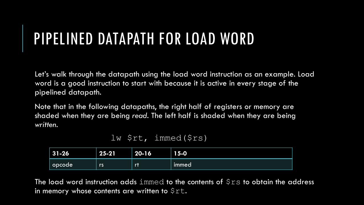
Let’s walk through the datapath using the load word instruction as an example. Load word is a good instruction to start with because it is active in every stage of the pipelined datapath.
Note that in the following datapaths, the right half of registers or memory are shaded when they are being read. The left half is shaded when they are being written.
The load word instruction adds immed to the contents of $rs to obtain the address in memory whose contents are written to $rt.
lw $rt, immed($rs)
31-26 25-21 20-16 15-0
opcode rs rt immed

PIPELINED DATAPATH FOR LOAD WORD
Instruction Fetch (IF)
• The instruction is read from memory using the contents of PC and placed in the IF/ID register.
• The PC address is incremented by 4 and written back to the PC register, as well as placed in the IF/ID register in case the instruction needs it later.
Note: the datapath does not know that we are performing a load word at this point so it forwards the PC+4 value just in case.

PIPELINED DATAPATH FOR LOAD WORD: IF
PIPELINED DATAPATH FOR LOAD WORD
Instruction Decode and Register File Read (ID):
• The registers $rs and $rt are read from the register file and stored in the ID/EX pipeline register. Remember, we don’t know what the instruction is yet.
• The 16-bit immediate field is sign-extended to 32-bits and stored in the ID/EX pipeline register.
• The PC+4 value is copied from the IF/ID register into the ID/EX register in case the instruction needs it later.

PIPELINED DATAPATH FOR LOAD WORD: ID

PIPELINED DATAPATH FOR LOAD WORD
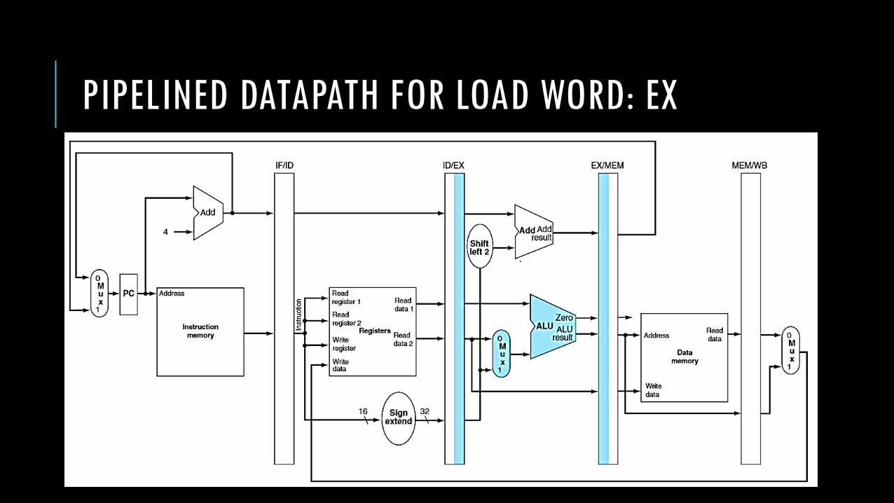
Execute or Address Calculation (EX):
• From the ID/EX pipeline register, take the contents of $rs and the sign-extended immediate field as inputs to the ALU, which performs an add operation. The sum is placed in the EX/MEM pipeline register.
PIPELINED DATAPATH FOR LOAD WORD: EX
PIPELINED DATAPATH FOR LOAD WORD
Memory Access (MEM):
• Take the address stored in the EX/MEM pipeline register and use it to access data memory. The data read from memory is stored in the MEM/WB pipeline register.

PIPELINED DATAPATH FOR LOAD WORD: MEM

PIPELINED DATAPATH FOR LOAD WORD
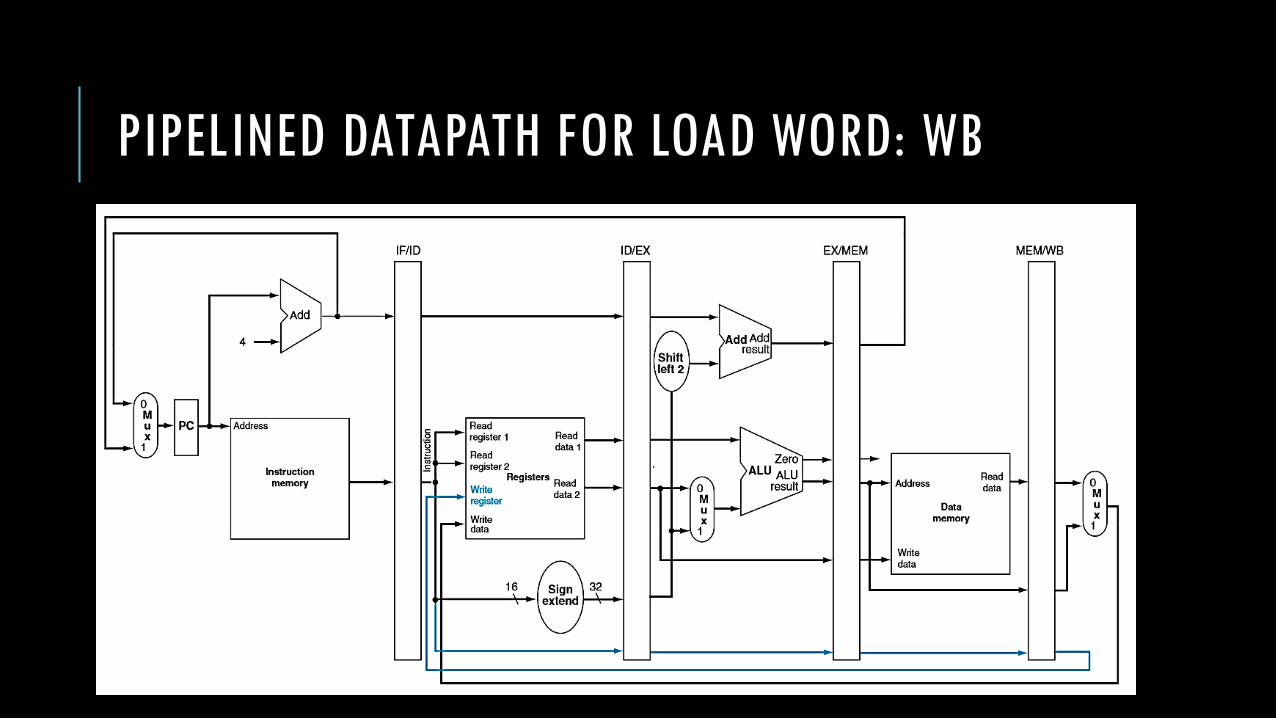
Write Back (WB):
• Read the data from the MEM/WB register and write it back to the register file in the middle of the datapath.

PIPELINED DATAPATH FOR LOAD WORD: WB

PIPELINED DATAPATH FOR LOAD WORD
It’s important to note that any information we need will have to be passed from pipeline register to pipeline register while instruction executes.
Because the instructions share the elements, we cannot assume anything from a previous cycle is still there. We must carry the data with us as we move along the data path.
So by now you should be wondering about the last step. How does the WB stage know which register to write to? The IF/ID pipeline register should no longer contain the necessary instruction field – it’s already been overwritten by three other instructions at this point.
We’ll see the solution soon, but let’s look at store word first.

PIPELINED DATAPATH FOR STORE WORD
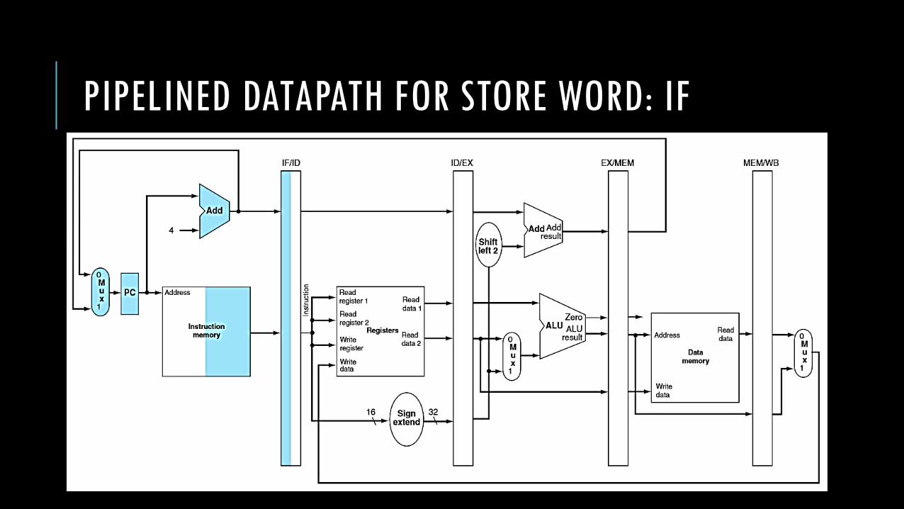
The IF and ID stages are identical for all instructions.
At these stages of execution, we still do not know which instruction we are actually executing so we perform general operations that either apply to all instructions or may speculatively apply to a select few instructions.
PIPELINED DATAPATH FOR STORE WORD: IF

PIPELINED DATAPATH FOR STORE WORD: ID

PIPELINED DATAPATH FOR STORE WORD
Execute or Address Calculation (EX):
• From the ID/EX pipeline register, take the contents of $rs and the sign-extended immediate field as inputs to the ALU, which performs an add operation. The sum is placed in the EX/MEM pipeline register.
• The contents of the $rt register are copied from the ID/EX pipeline register to the EX/MEM pipeline register.

PIPELINED DATAPATH FOR STORE WORD: EX

PIPELINED DATAPATH FOR STORE WORD
Memory Access (MEM):
• Take the address stored in the EX/MEM pipeline register and use it to access data memory.
• Take the contents of $rt from the EX/MEM pipeline and write it to data memory at the address specified.
Note that in order to use the $rt field in the MEM stage, we have to carry it with us from the ID stage. This means copying it in every pipeline register until we use it.

PIPELINED DATAPATH FOR STORE WORD: MEM

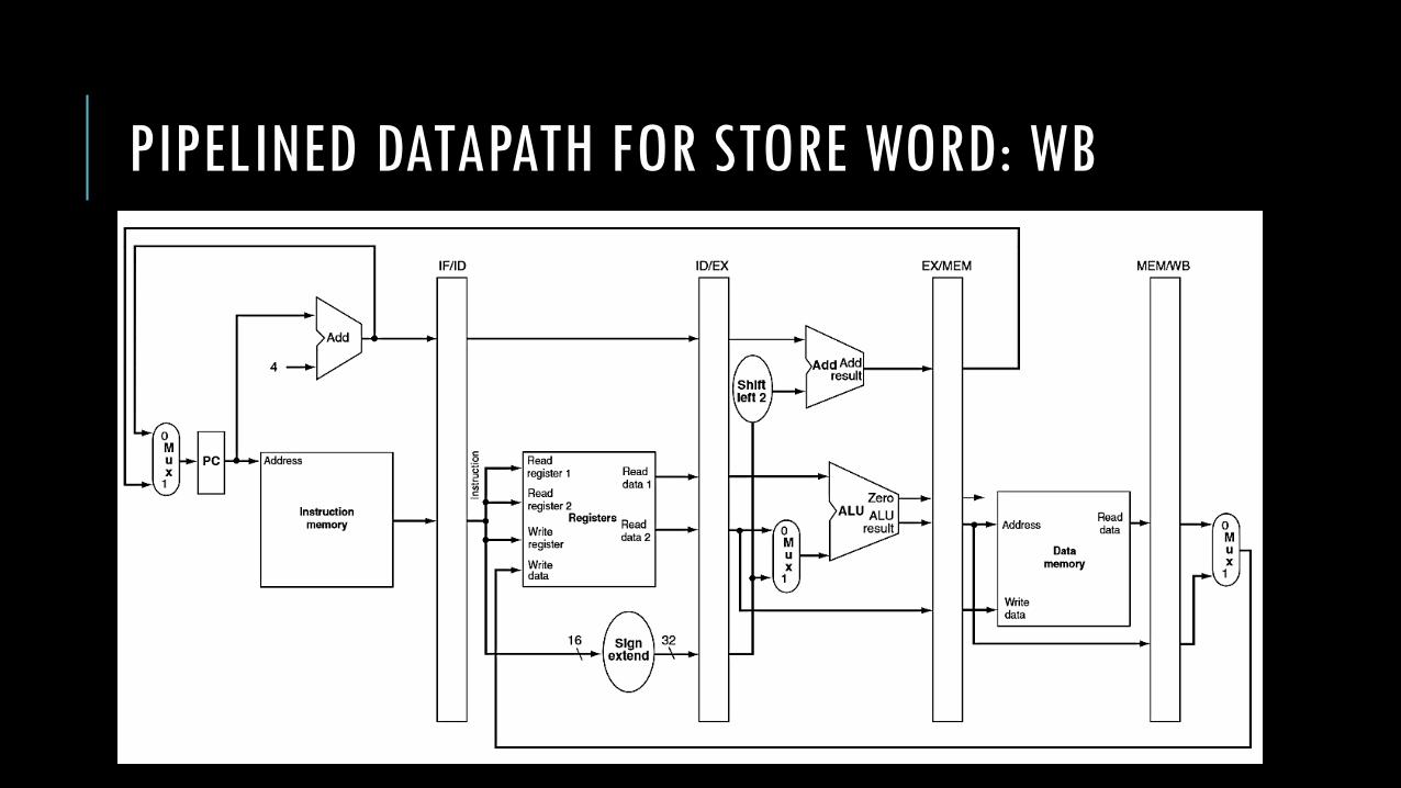
PIPELINED DATAPATH FOR STORE WORD
Write Back (WB):
• We’re already done with the store word instruction so we don’t have to do anything.
PIPELINED DATAPATH FOR STORE WORD: WB

PIPELINED DATAPATH
In both the load and store word datapaths, we can notice another important point: every datapath element is used in only one pipeline stage. If this wasn’t the case, we’d create a structural hazard.
Let’s say we used the ALU from the EX stage to both increment PC in the IF stage and perform operations in the EX stage. This is fine for a single instruction, but what happens if we’re executing multiple instructions and one is currently in the IF stage and another is in the EX stage? Which one gets to use the ALU?
Clearly, we’d have an issue. So, we add redundancy to our datapath in order to gain the speed improvements from pipelining.

PIPELINED DATAPATH FOR LOAD WORD
Ok, so let’s look back at load word’s WB stage.
Remember that we have a problem? We don’t know to which register we need to write back. What’s the solution?

PIPELINED DATAPATH FOR LOAD WORD: WB

PIPELINED DATAPATH FOR LOAD WORD
Ok, so let’s look back at load word’s WB stage.
Remember that we have a problem? We don’t know to which register we need to write back. What’s the solution?
That’s right! Carry the information through each stage using the pipeline registers. To do this, we’ll modify the datapath a little bit.
Now, we’ll pass the write register number from the MEM/WB pipeline register along with the data. This register number is initially discovered in the ID stage and must be passed through the pipeline registers until we need it in the WB stage.
PIPELINED DATAPATH FOR LOAD WORD: WB
PIPELINED DATAPATH
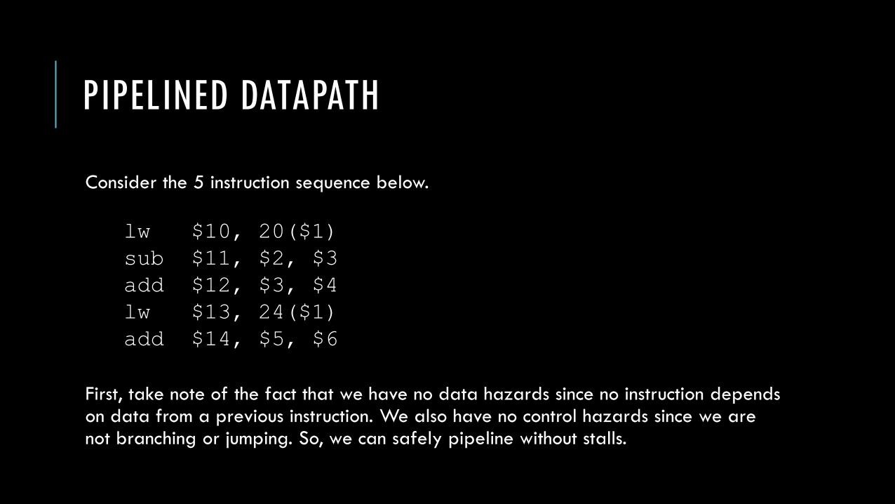
Consider the 5 instruction sequence below.
First, take note of the fact that we have no data hazards since no instruction depends on data from a previous instruction. We also have no control hazards since we are not branching or jumping. So, we can safely pipeline without stalls.
lw $10, 20($1)
sub $11, $2, $3
add $12, $3, $4
lw $13, 24($1)
add $14, $5, $6
PIPELINED DATAPATH
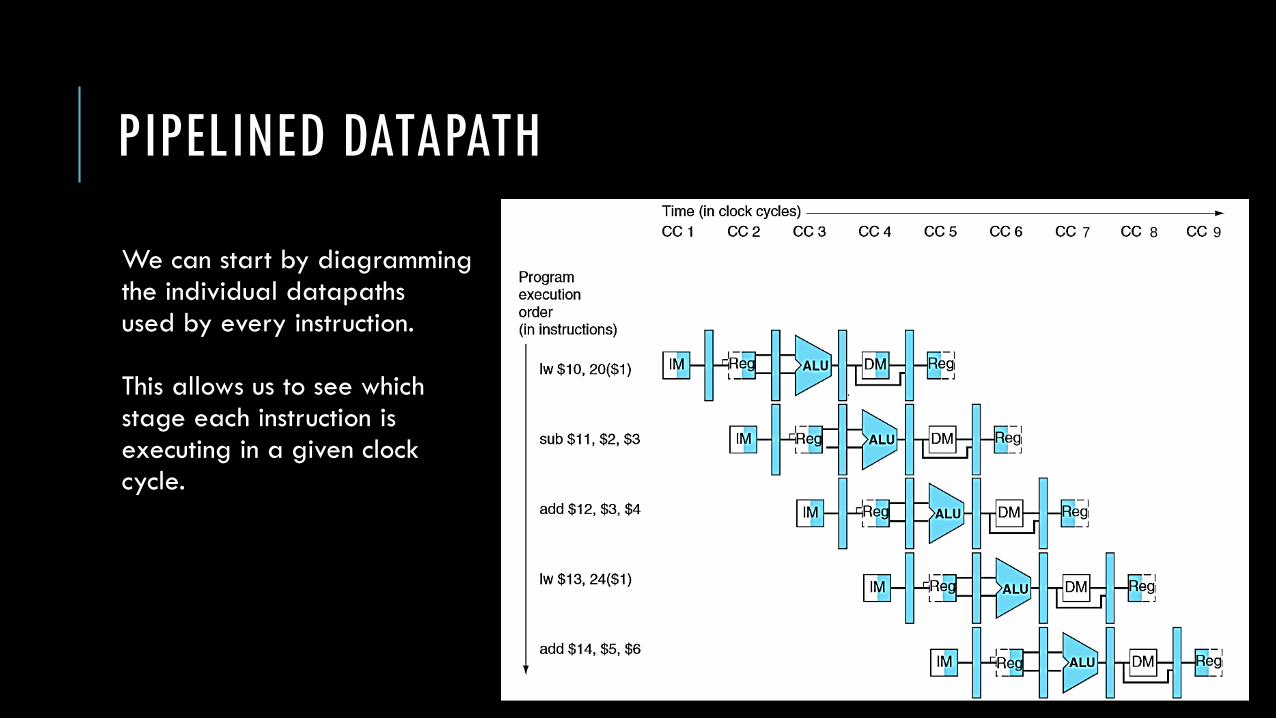
We can start by diagrammingthe individual datapathsused by every instruction.
This allows us to see which stage each instruction is executing in a given clock cycle.
7 8 9

PIPELINED DATAPATH
We can also chart the stages themselves rather than the elements being used in the cycle.
7 8 9
PIPELINED DATAPATH
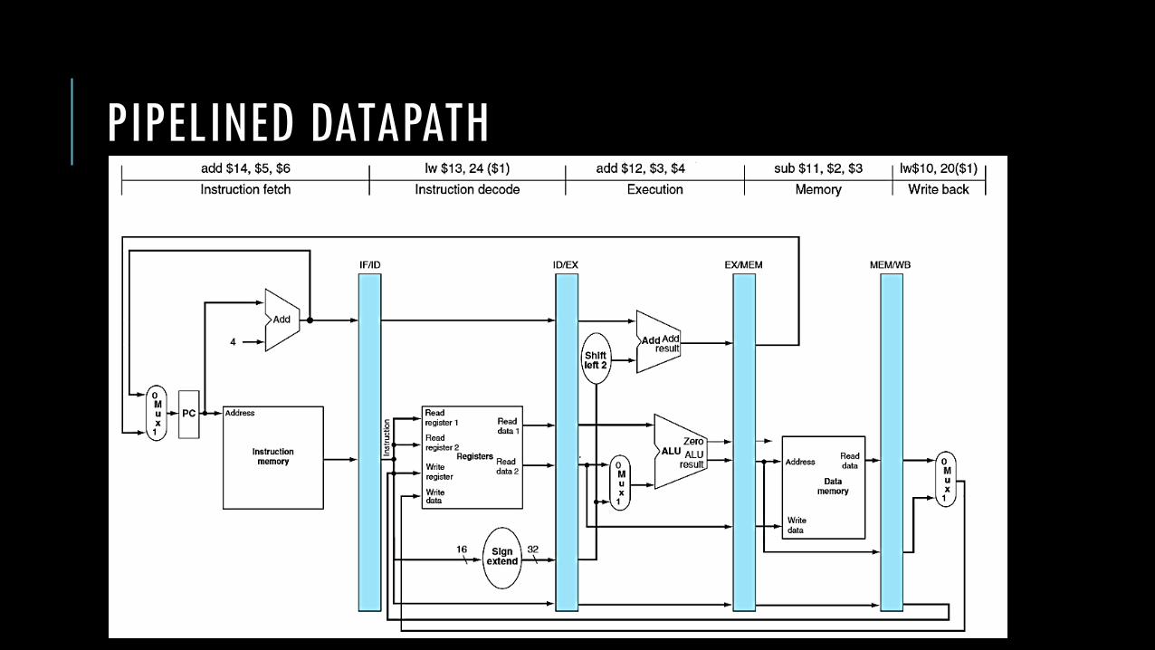
On the next slide, we show a single datapath as it is being used by the 5 instructions at once.
The cycle depicted is cycle 5. In this cycle, the first load word is executing its WB stage while the last add instruction is executing its IF stage.
PIPELINED DATAPATH

PIPELINED DATAPATH

PIPELINED DATAPATH
In the following slides, we walk through all 9 cycles required to fully complete the 5 instructions in our sample sequence.
We will start with clock cycle 1 and highlight the relevant datapath lines according to the instruction being executed in each particular stage.
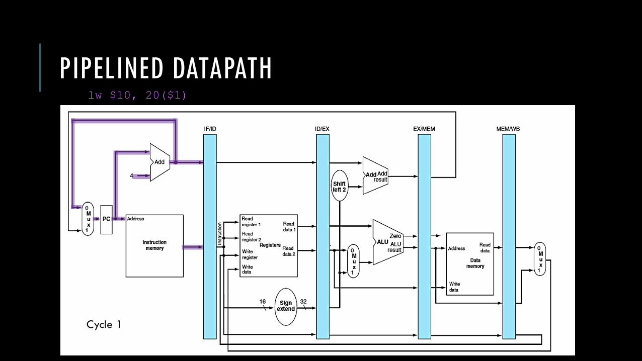
PIPELINED DATAPATHlw $10, 20($1)
Cycle 1
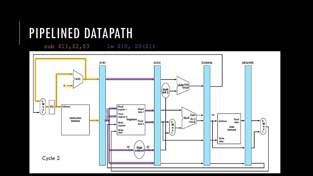
PIPELINED DATAPATHlw $10, 20($1)sub $11,$2,$3
Cycle 2
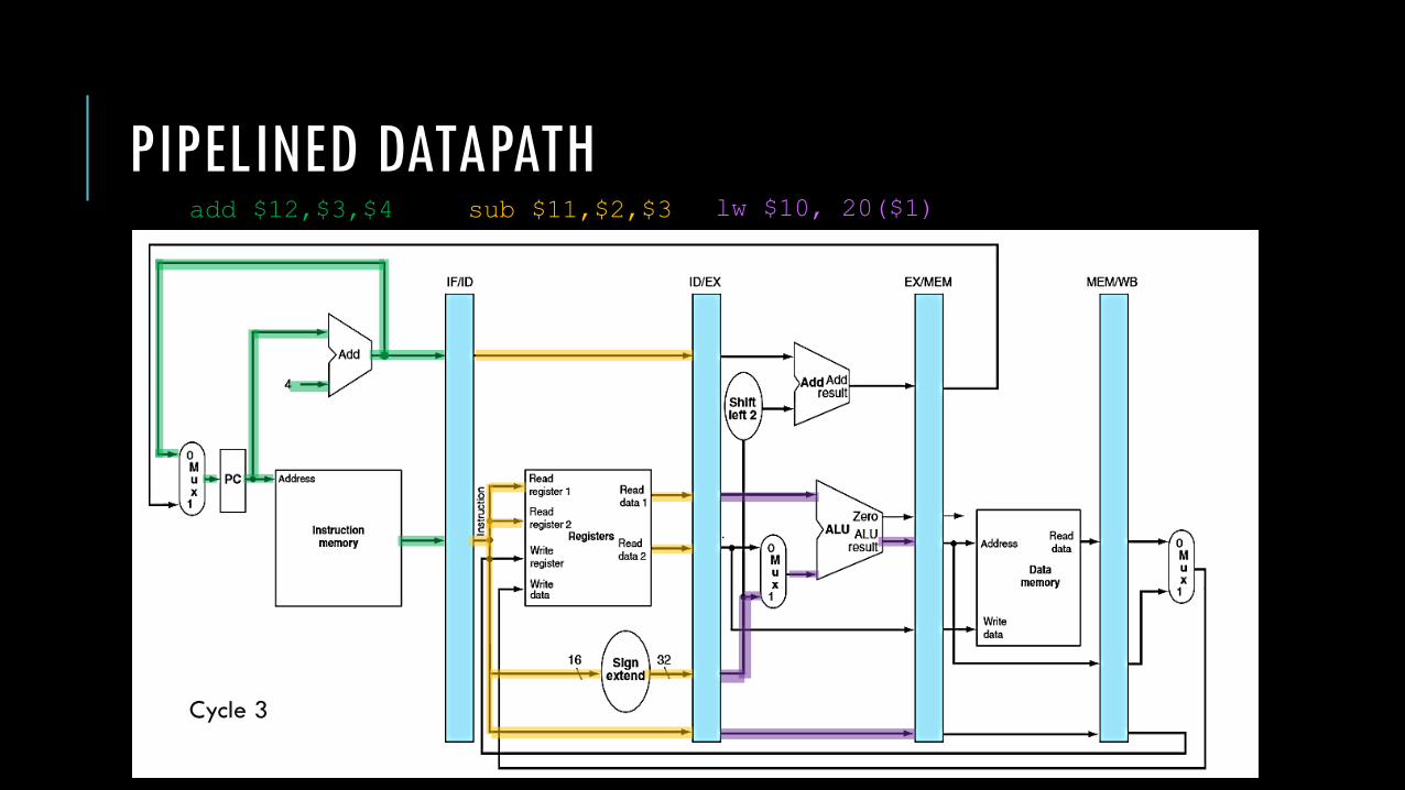
PIPELINED DATAPATHlw $10, 20($1)sub $11,$2,$3add $12,$3,$4
Cycle 3
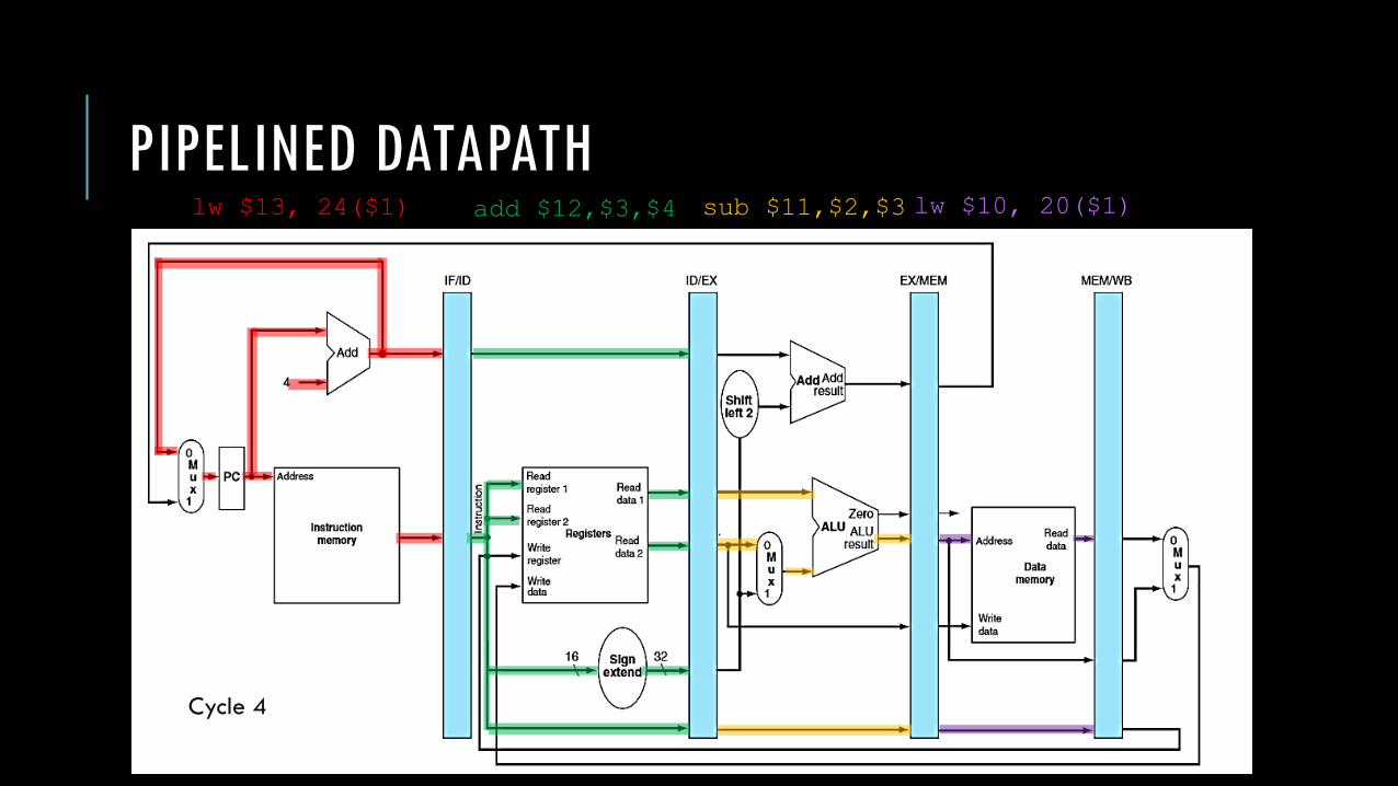
PIPELINED DATAPATHlw $10, 20($1)sub $11,$2,$3add $12,$3,$4lw $13, 24($1)
Cycle 4

PIPELINED DATAPATHlw $10, 20($1)sub $11,$2,$3add $12,$3,$4lw $13, 24($1)add $14,$5,$6
Cycle 5
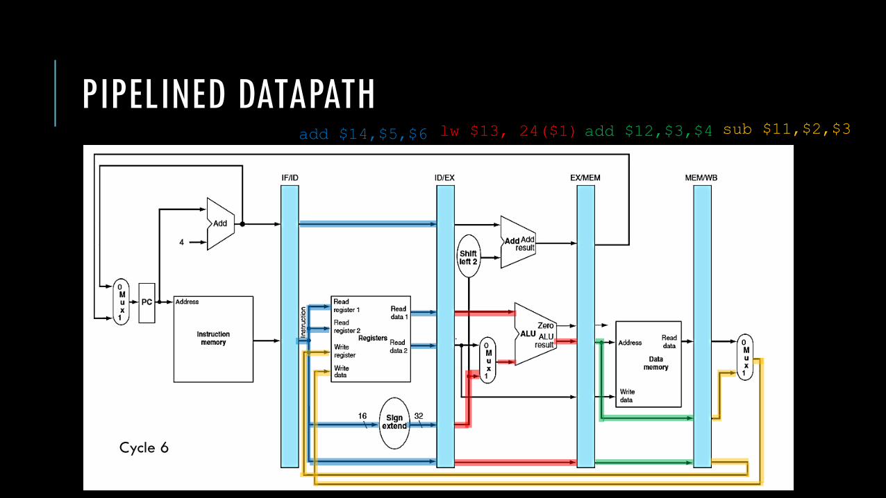
PIPELINED DATAPATHsub $11,$2,$3add $12,$3,$4lw $13, 24($1)add $14,$5,$6
Cycle 6

PIPELINED DATAPATHadd $12,$3,$4lw $13, 24($1)add $14,$5,$6
Cycle 7

PIPELINED DATAPATHlw $13, 24($1)add $14,$5,$6
Cycle 8

PIPELINED DATAPATHadd $14,$5,$6
Cycle 9

PIPELINED CONTROL
Now, let’s add control to our pipelined datapath. We’ll start with a simple control scheme and deal with pipeline hazards later.
A lot of the control logic is borrowed from the single-cycle and multi-cycle implementations.

PIPELINED CONTROL

PIPELINED CONTROL
Let’s remind ourselves of the roles of these control lines.
Opcode ALU
op
Operation Funct ALU
action
ALU
Control
Input
lw 00 Load word N/A add 0010
sw 00 Store word N/A add 0010
beq 01 Branch equal N/A subtract 0110
R-type 10 Add 100000 add 0010
R-type 10 Subtract 100010 subtract 0110
R-type 10 AND 100100 AND 0000
R-type 10 OR 100101 OR 0001
R-type 10 Set on less than 101010 slt 0111

PIPELINED CONTROL
1-Bit Signal Name Effect When Deasserted Effect When Asserted
RegDst The register file destination number for the
Write register comes from the rt field.
The register file destination number for the Write
register comes from the rd field.
RegWrite None Write register is written with the value of the Write
data input.
ALUSrc The first ALU operand is Read Data 2. The first ALU operand is sign-ext immediate field.
PCSrc PC is replaced by PC+4. PC is replaced by branch target.
MemRead None Content of memory at the location specified by the
Address input is put on the Memory data output.
MemWrite None The Write Data input is written to the Address input.
MemtoReg The value fed to the register file is from the
ALU.
The value fed to the register file input comes from
Memory.
PIPELINED CONTROL
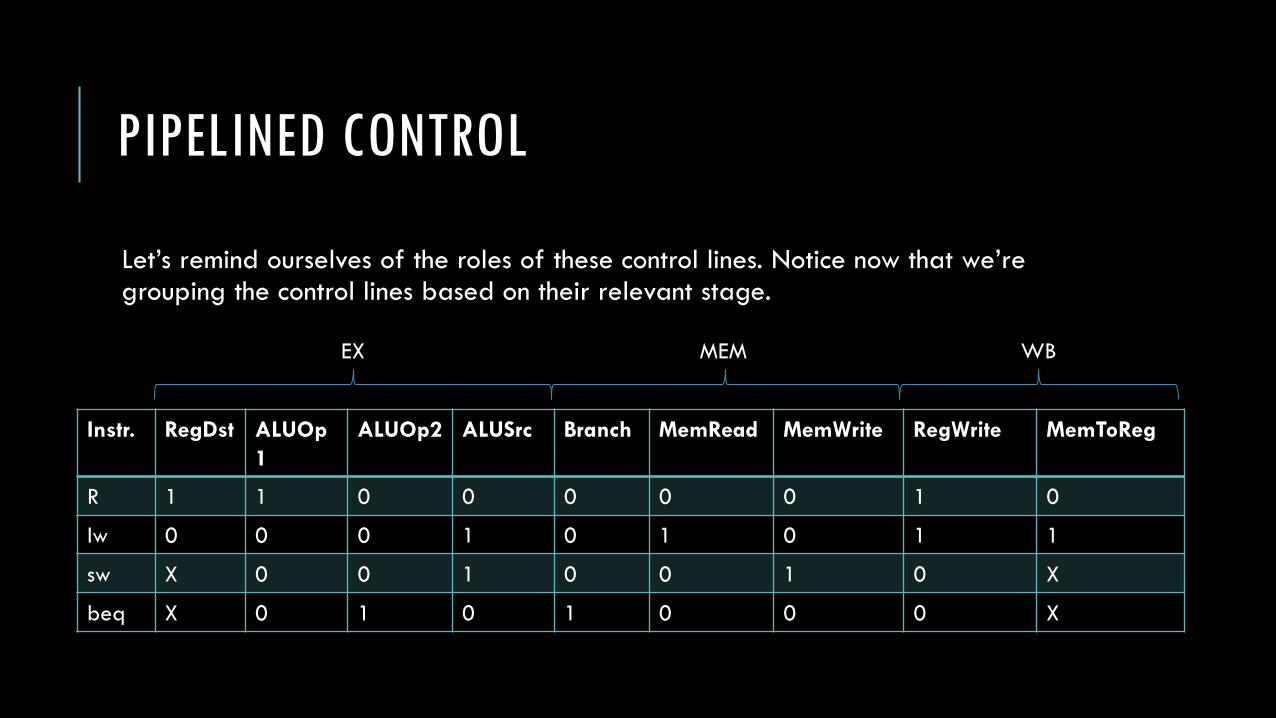
Let’s remind ourselves of the roles of these control lines. Notice now that we’re grouping the control lines based on their relevant stage.
Instr. RegDst ALUOp
1
ALUOp2 ALUSrc Branch MemRead MemWrite RegWrite MemToReg
R 1 1 0 0 0 0 0 1 0
lw 0 0 0 1 0 1 0 1 1
sw X 0 0 1 0 0 1 0 X
beq X 0 1 0 1 0 0 0 X
EX MEM WB
PIPELINED CONTROL
Unlike the multi-cycle implementation, we assume that the PC is written on every clock cycle so there is no explicit control signal for writing PC. We also assume that the pipeline registers are written on every clock cycle.
As we just saw in the previous slide, we can handle “controlling” 5 instructions at once by dividing the control signals into 5 groups – one for each pipeline stage.
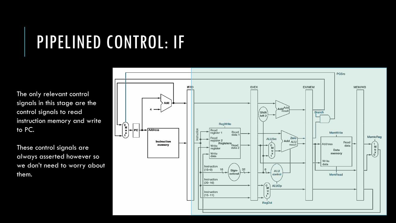
PIPELINED CONTROL: IF
The only relevant control
signals in this stage are the
control signals to read
instruction memory and write
to PC.
These control signals are
always asserted however so
we don’t need to worry about
them.
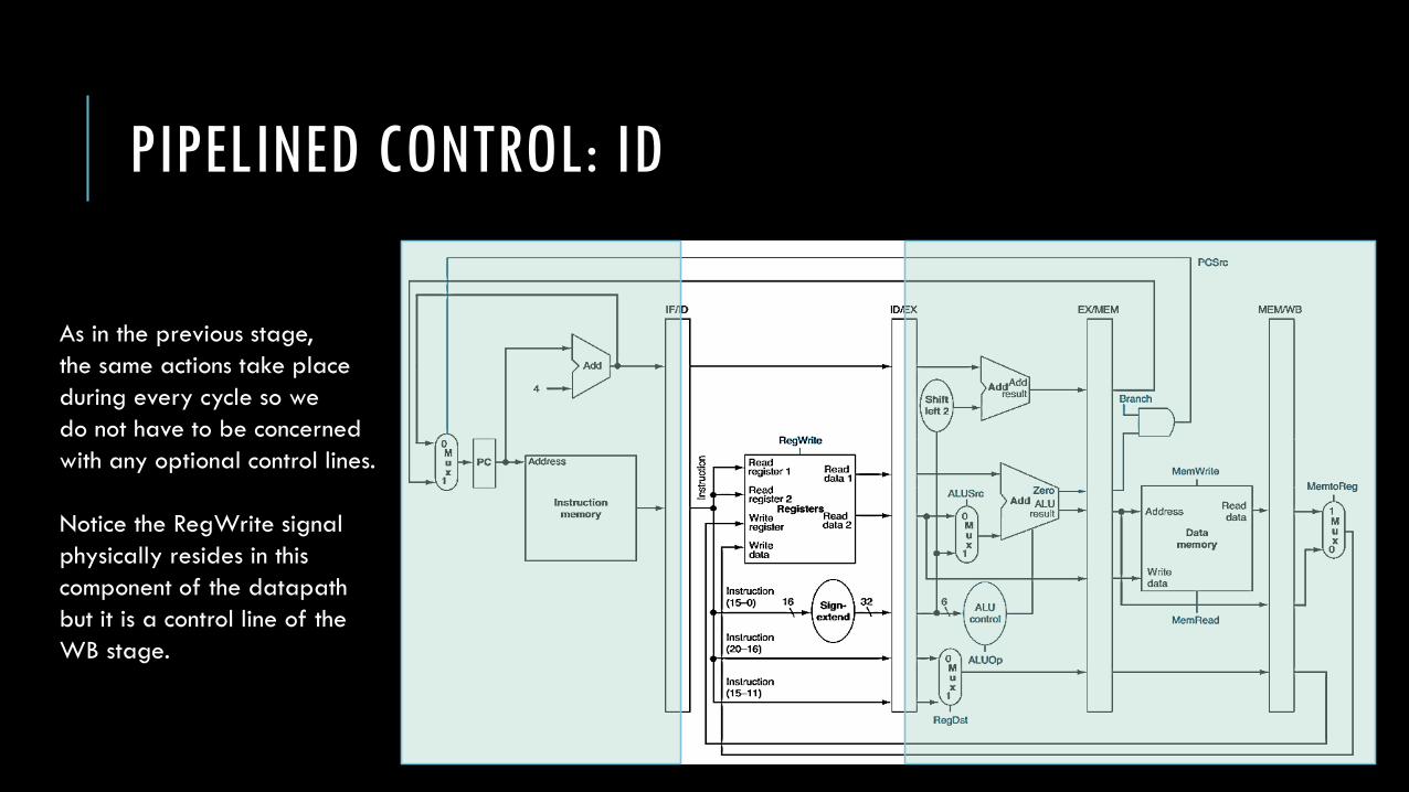
PIPELINED CONTROL: ID
As in the previous stage,
the same actions take place
during every cycle so we
do not have to be concerned
with any optional control lines.
Notice the RegWrite signal
physically resides in this
component of the datapath
but it is a control line of the
WB stage.

PIPELINE CONTROL: EX
The relevant control signals
in this stage are:
• RegDst
• ALUOp
• ALUSrc
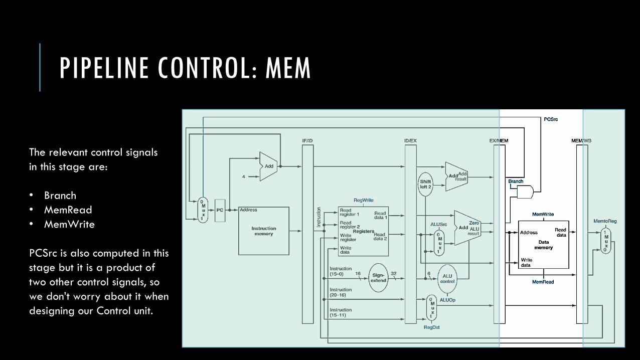
PIPELINE CONTROL: MEM
The relevant control signals
in this stage are:
• Branch
• MemRead
• MemWrite
PCSrc is also computed in this
stage but it is a product of
two other control signals, so
we don’t worry about it when
designing our Control unit.

PIPELINE CONTROL: WB
The relevant control signals
in this stage are:
• MemtoReg
• RegWrite
Note that RegWrite is our one
exception. It actually appears
in ID’s phase of the pipeline
but it is a control signal for the
WB stage.

PIPELINED CONTROL
As before, we need to preserve the context of an instruction as it moves through the datapath.
We cannot reach back in the datapath for some information about how to execute the instruction –it will have already been overwritten.
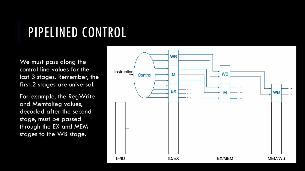
PIPELINED CONTROL
We must pass along the control line values for the last 3 stages. Remember, the first 2 stages are universal.
For example, the RegWriteand MemtoReg values, decoded after the second stage, must be passed through the EX and MEM stages to the WB stage.
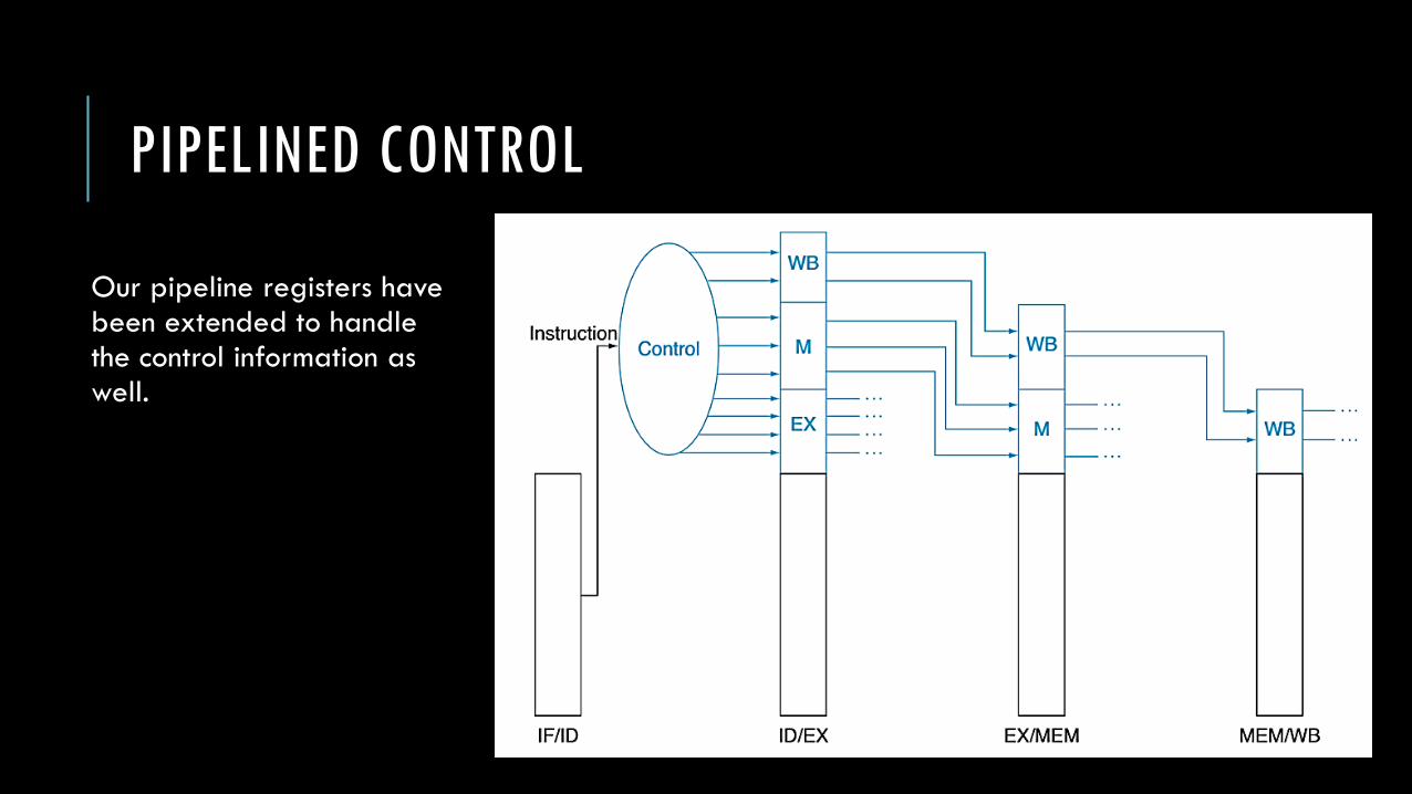
PIPELINED CONTROL
Our pipeline registers havebeen extended to handle the control information as well.


PIPELINED CONTROL
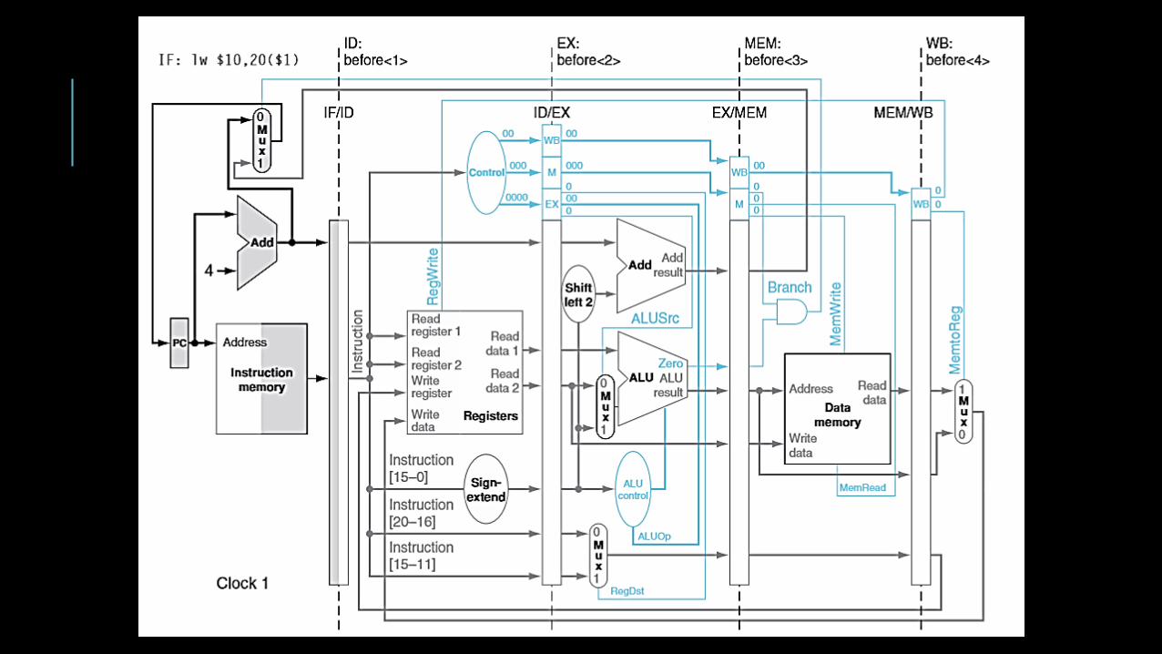
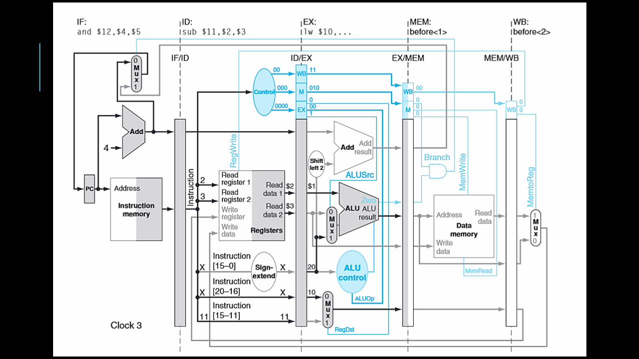
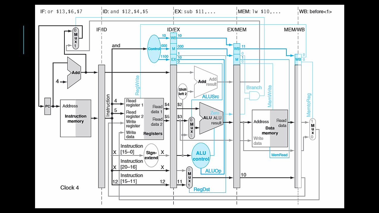
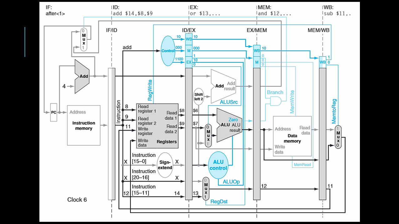
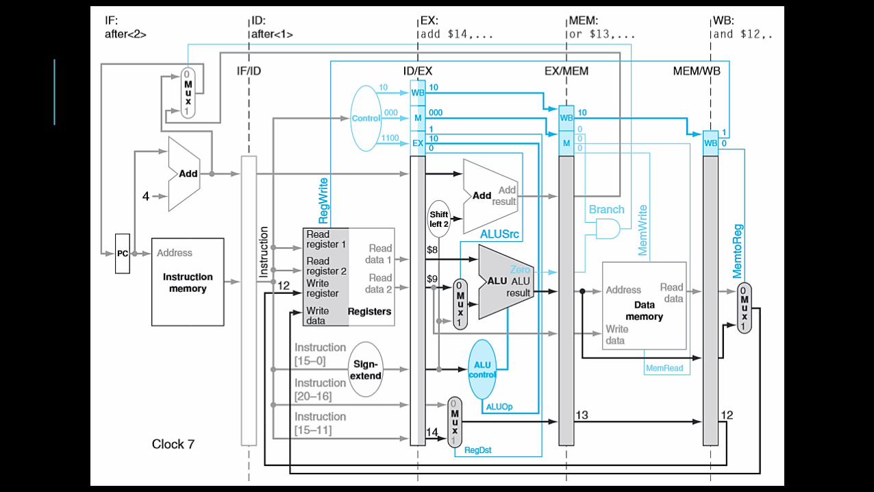
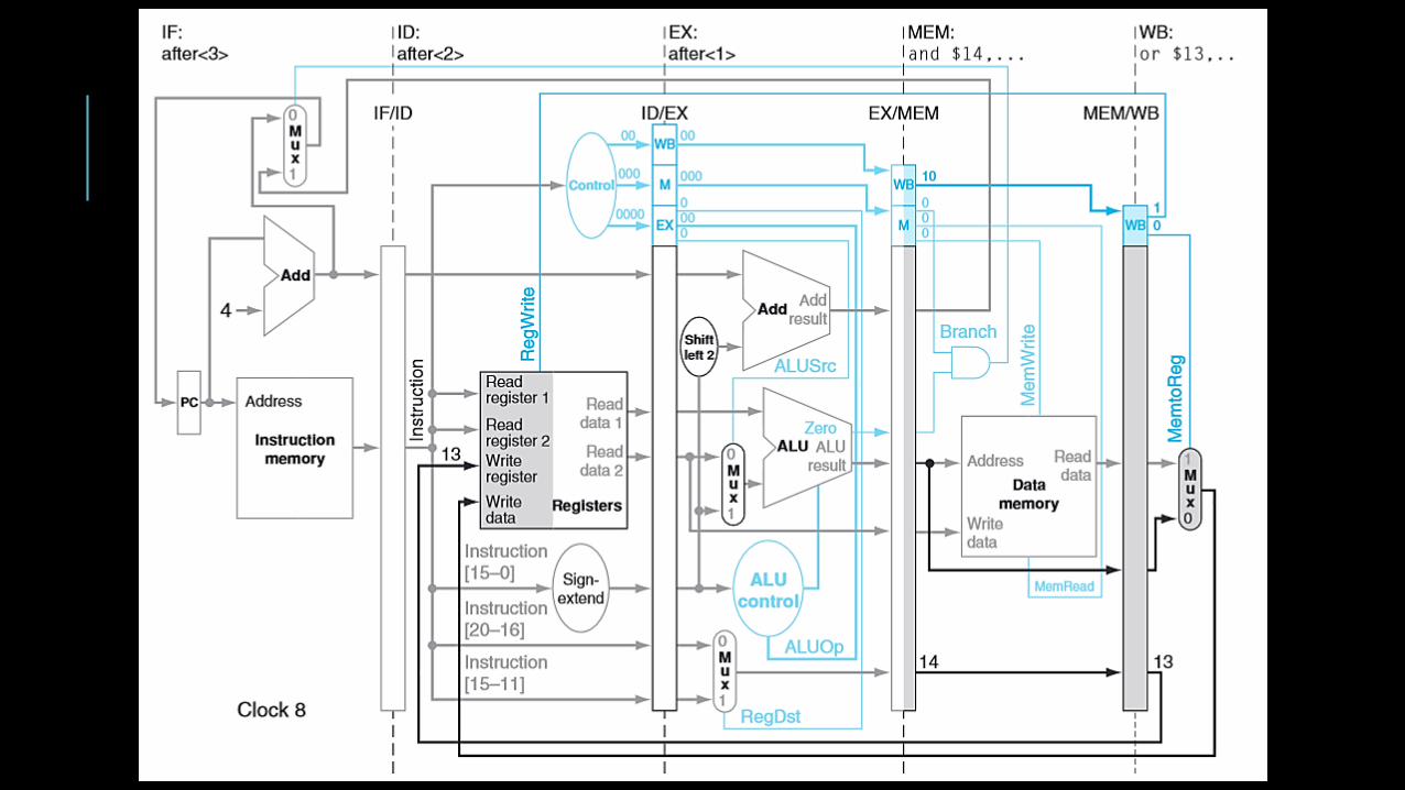
Consider the following instructions.
Let’s examine, in all the gory detail, how these simple instructions are executed in a pipelined datapath. Note again that we have no control or data hazards. Each slide following will show the datapath state in a subsequent clock cycle.
lw $10, 20($1)
sub $11, $2, $3
and $12, $4, $5
or $13, $6, $7
add $14, $8, $9


![20-Pipelining-datapath-control.ppt [Modo de compatibilidad]euler.mat.uson.mx/~havillam/ca/Slides/20-Pipelining... · 2020-03-12 · Universidad de Sonora Arquitectura de Computadoras](https://img.dokumen.tips/doc/110x75/5f76224e9d3807622a5d4895/20-pipelining-datapath-modo-de-compatibilidadeulermatusonmxhavillamcaslides20-pipelining.jpg)


![Pipelining & Parallel Processing - ics.kaist.ac.krics.kaist.ac.kr/ee878_2018f/[EE878]3 Pipelining and Parallel Processing.pdf · Pipelining processing By using pipelining latches](https://img.dokumen.tips/doc/110x75/5d40e26d88c99391748d47fb/pipelining-parallel-processing-icskaistackricskaistackree8782018fee8783.jpg)