Embed Size (px)
Citation preview
Lecture 8: Memory Management
Lecture 8 / Page 2 AE4B33OSS Silberschatz, Galvin and Gagne ©2005
Contents
Problems of memory management Dynamic allocation Memory fragmentation Paging Address translation with paging Paging hardware Page table architectures Segmentation Examples
Lecture 8 / Page 3 AE4B33OSS Silberschatz, Galvin and Gagne ©2005
Background
Program must be brought into memory and placed within a process memory space for it to be executed
Input queue – collection of processes on the disk that are waiting to be brought into memory to run the program
User programs go through several steps before being run
Lecture 8 / Page 4 AE4B33OSS Silberschatz, Galvin and Gagne ©2005
Binding of Instructions and Data to Memory
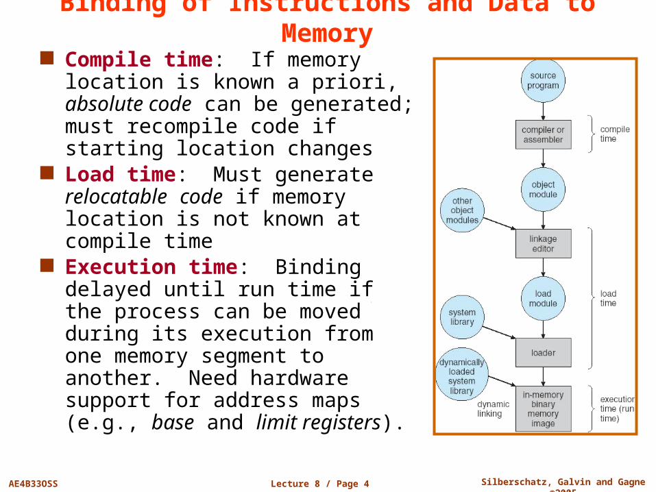
Compile time: If memory location is known a priori, absolute code can be generated; must recompile code if starting location changes
Load time: Must generate relocatable code if memory location is not known at compile time
Execution time: Binding delayed until run time if the process can be moved during its execution from one memory segment to another. Need hardware support for address maps (e.g., base and limit registers).
Lecture 8 / Page 5 AE4B33OSS Silberschatz, Galvin and Gagne ©2005
Logical vs. Physical Address Space
The concept of a logical address space that is bound to a separate physical address space is central to proper memory management Logical address – generated by the CPU; also referred to as
virtual address Physical address – the address seen by the memory unit
Logical and physical addresses are the same in compile-time and load-time address-binding schemes; logical (virtual) and physical addresses differ in execution-time address-binding scheme
Lecture 8 / Page 6 AE4B33OSS Silberschatz, Galvin and Gagne ©2005
Memory-Management Unit (MMU)
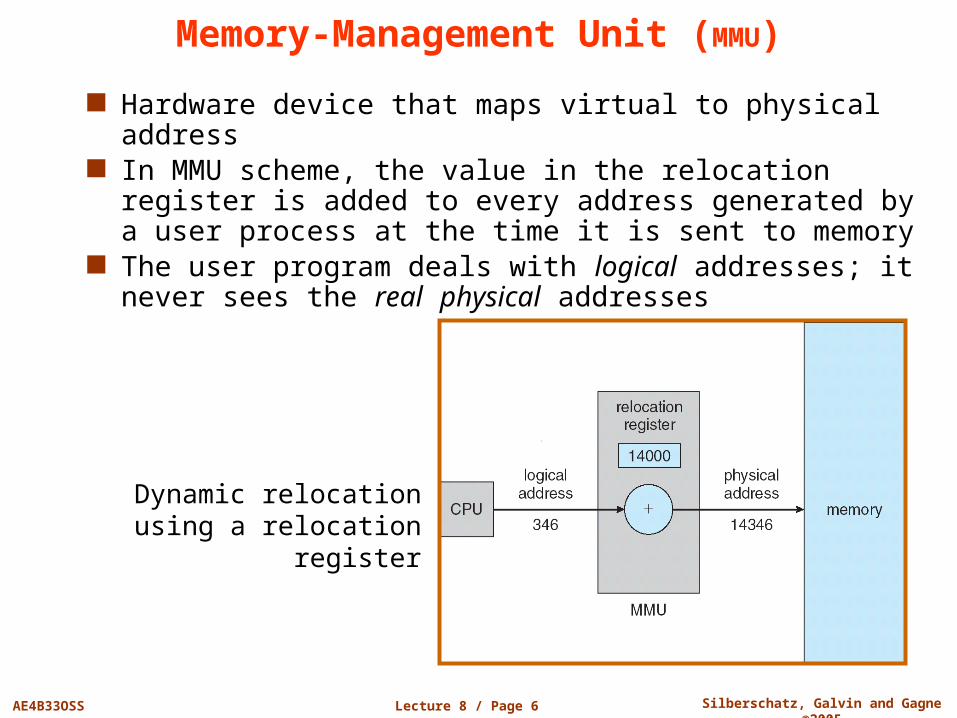
Hardware device that maps virtual to physical address In MMU scheme, the value in the relocation register is
added to every address generated by a user process at the time it is sent to memory
The user program deals with logical addresses; it never sees the real physical addresses
Dynamic relocation using a relocation register
Lecture 8 / Page 7 AE4B33OSS Silberschatz, Galvin and Gagne ©2005
Dynamic Loading
Routine is not loaded until it is called Better memory-space utilization; unused routine is never
loaded Useful when large amounts of code are needed to handle
infrequently occurring cases No special support from the operating system is required;
implemented through program design (overlays)
Lecture 8 / Page 8 AE4B33OSS Silberschatz, Galvin and Gagne ©2005
Dynamic Linking
Linking postponed until execution time Small piece of code, stub, placed instead of the real
procedure call – used to locate the appropriate memory-resident library routine
Stub replaces itself with the address of the routine, and executes the routine
Operating system support needed to check if the routine is in memory and addressable by the process
Dynamic linking is particularly useful for libraries
Lecture 8 / Page 9 AE4B33OSS Silberschatz, Galvin and Gagne ©2005
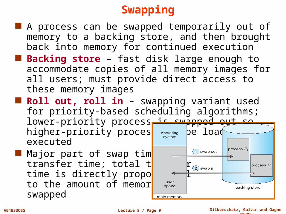
Swapping A process can be swapped temporarily out of memory to a
backing store, and then brought back into memory for continued execution
Backing store – fast disk large enough to accommodate copies of all memory images for all users; must provide direct access to these memory images
Roll out, roll in – swapping variant used for priority-based scheduling algorithms; lower-priority process is swapped out so higher-priority process can be loaded and executed
Major part of swap time is transfer time; total transfer time is directly proportional to the amount of memory swapped
Lecture 8 / Page 10 AE4B33OSS Silberschatz, Galvin and Gagne ©2005
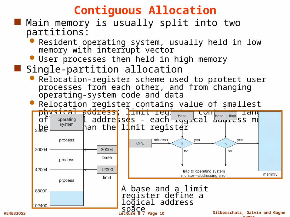
Contiguous Allocation Main memory is usually split into two partitions:
Resident operating system, usually held in low memory with interrupt vector
User processes then held in high memory Single-partition allocation
Relocation-register scheme used to protect user processes from each other, and from changing operating-system code and data
Relocation register contains value of smallest physical address; limit register contains range of logical addresses – each logical address must be less than the limit register
A base and a limit register define a logical address space
Lecture 8 / Page 11 AE4B33OSS Silberschatz, Galvin and Gagne ©2005
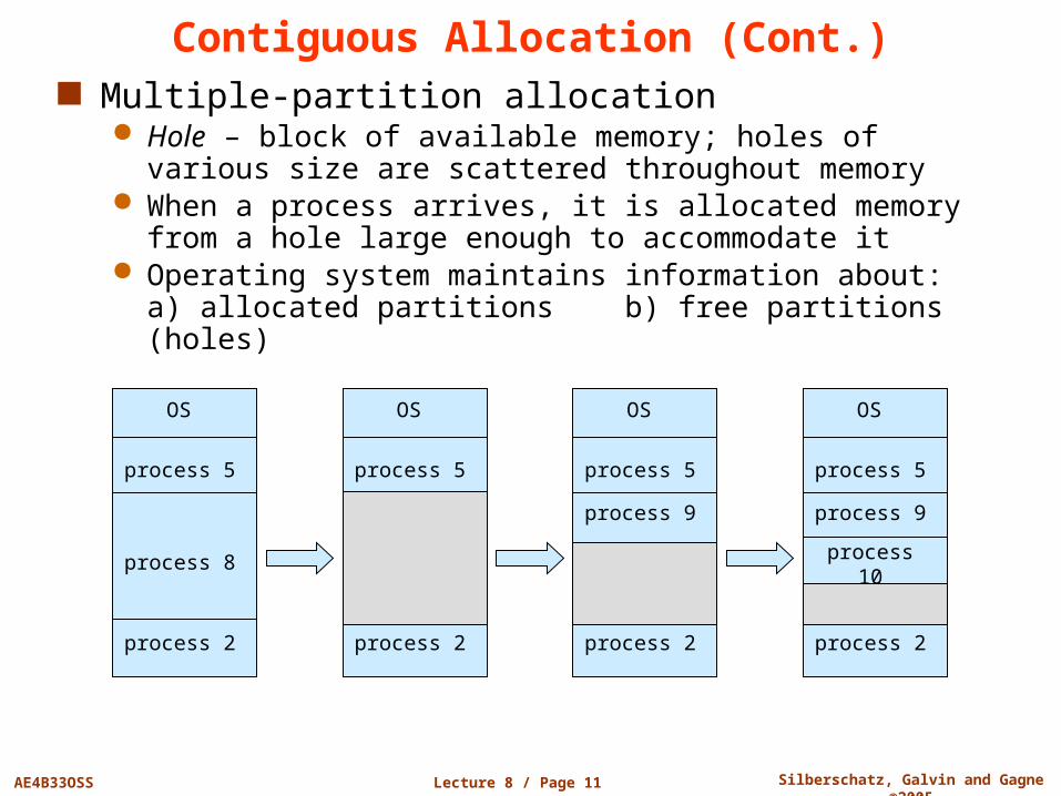
Contiguous Allocation (Cont.) Multiple-partition allocation
Hole – block of available memory; holes of various size are scattered throughout memory
When a process arrives, it is allocated memory from a hole large enough to accommodate it
Operating system maintains information about:a) allocated partitions b) free partitions (holes)
OS
process 5
process 8
process 2
OS
process 5
process 2
OS
process 5
process 2
OS
process 5
process 9
process 2
process 9
process 10
Lecture 8 / Page 12 AE4B33OSS Silberschatz, Galvin and Gagne ©2005
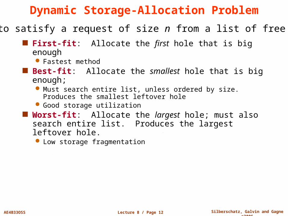
Dynamic Storage-Allocation Problem
First-fit: Allocate the first hole that is big enough Fastest method
Best-fit: Allocate the smallest hole that is big enough; Must search entire list, unless ordered by size. Produces the
smallest leftover hole Good storage utilization
Worst-fit: Allocate the largest hole; must also search entire list. Produces the largest leftover hole. Low storage fragmentation
How to satisfy a request of size n from a list of free holes
Lecture 8 / Page 13 AE4B33OSS Silberschatz, Galvin and Gagne ©2005
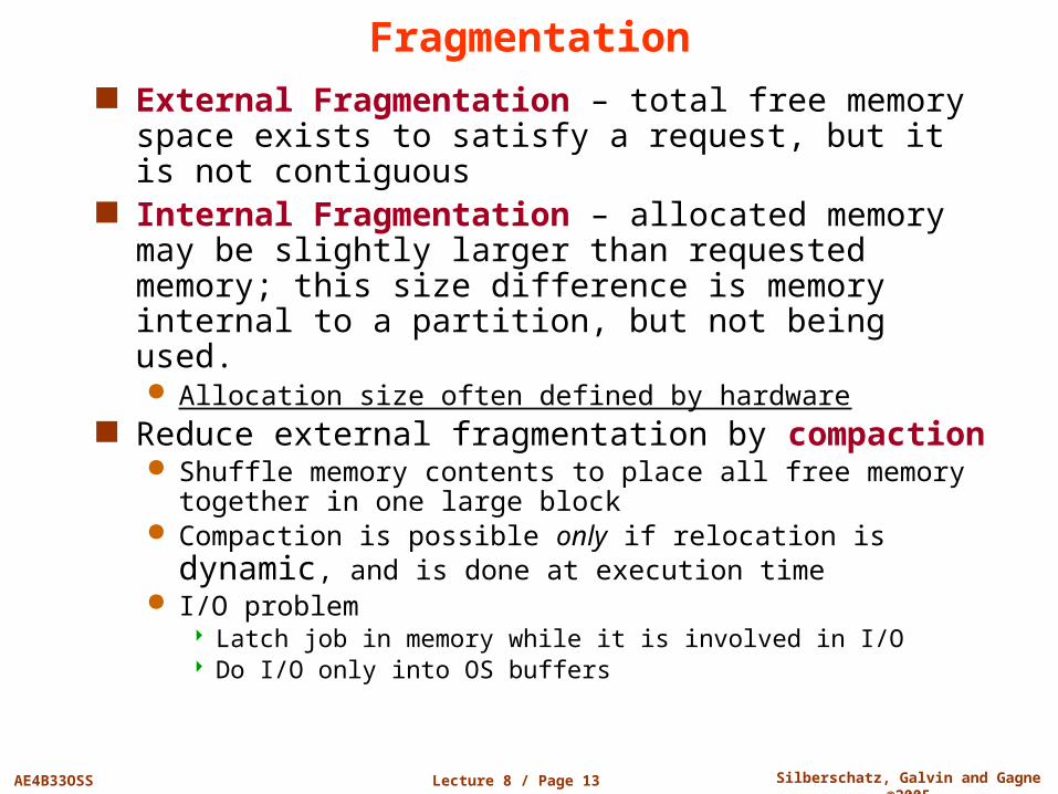
Fragmentation External Fragmentation – total free memory space
exists to satisfy a request, but it is not contiguous Internal Fragmentation – allocated memory may be
slightly larger than requested memory; this size difference is memory internal to a partition, but not being used. Allocation size often defined by hardware
Reduce external fragmentation by compaction Shuffle memory contents to place all free memory together in
one large block Compaction is possible only if relocation is dynamic, and is
done at execution time I/O problem
Latch job in memory while it is involved in I/O Do I/O only into OS buffers
Lecture 8 / Page 14 AE4B33OSS Silberschatz, Galvin and Gagne ©2005
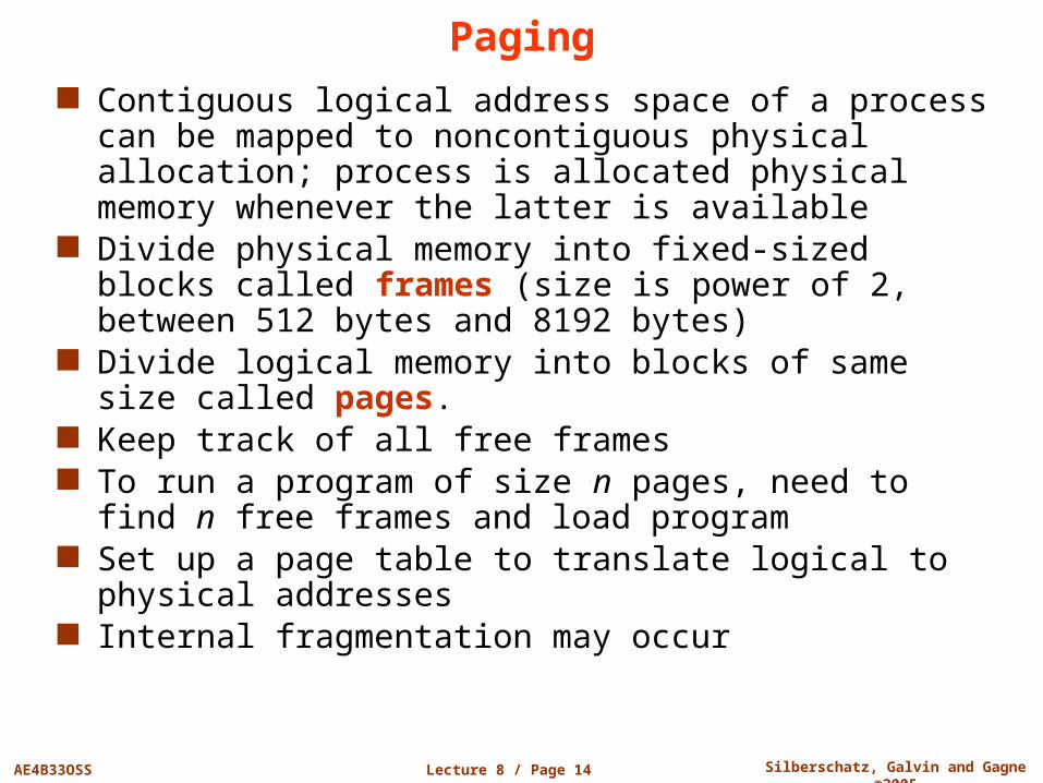
Paging Contiguous logical address space of a process can be
mapped to noncontiguous physical allocation; process is allocated physical memory whenever the latter is available
Divide physical memory into fixed-sized blocks called frames (size is power of 2, between 512 bytes and 8192 bytes)
Divide logical memory into blocks of same size called pages.
Keep track of all free frames To run a program of size n pages, need to find n free
frames and load program Set up a page table to translate logical to physical
addresses Internal fragmentation may occur
Lecture 8 / Page 15 AE4B33OSS Silberschatz, Galvin and Gagne ©2005
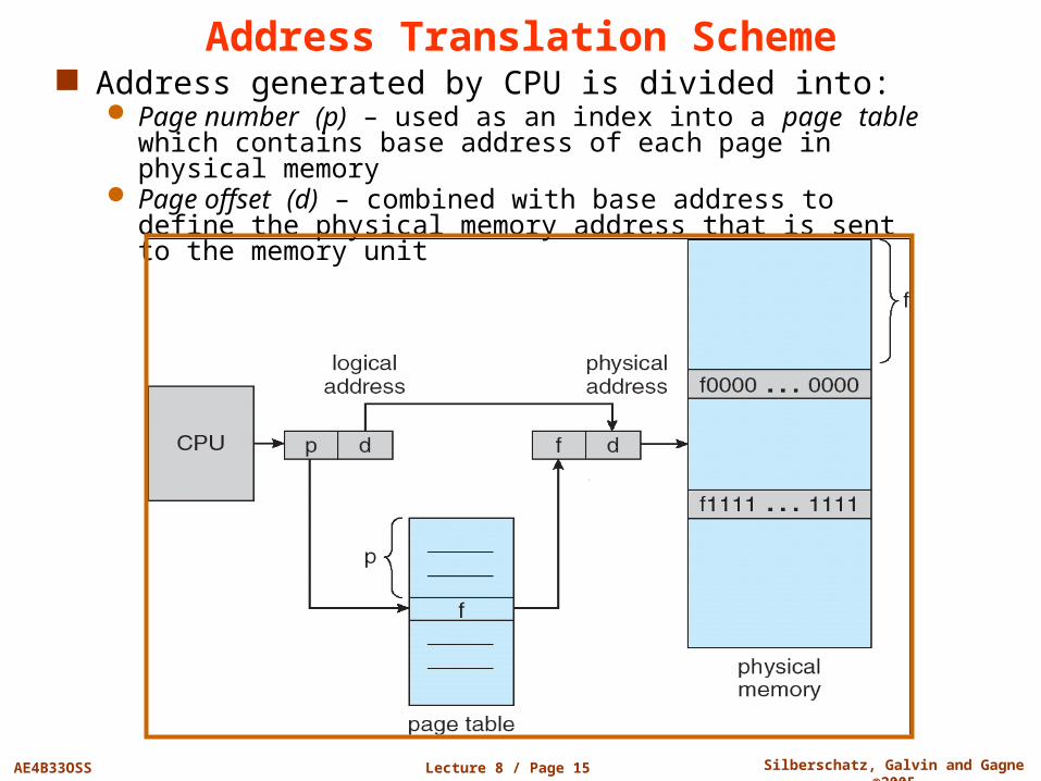
Address Translation Scheme Address generated by CPU is divided into:
Page number (p) – used as an index into a page table which contains base address of each page in physical memory
Page offset (d) – combined with base address to define the physical memory address that is sent to the memory unit
Lecture 8 / Page 16 AE4B33OSS Silberschatz, Galvin and Gagne ©2005
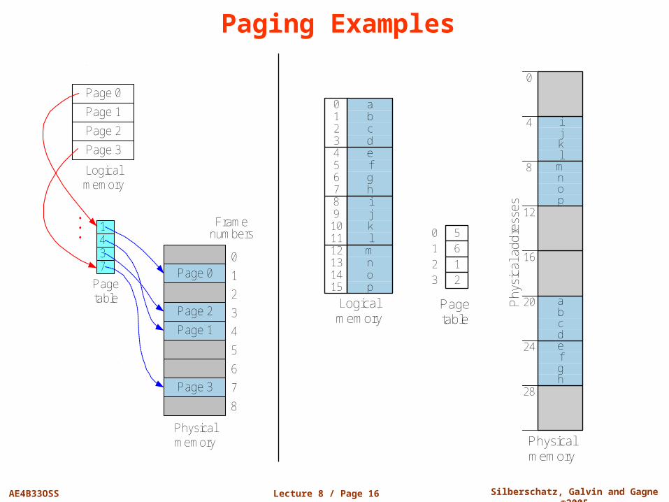
Paging Examples
Page table
0
1
2
3
5
6
1
2
Physical memory
0
28
24
20
16
12
8
4 i
lkj
e
hgf
a
dcb
m
pon
m
pon
i
lkj
12
151413
8
11109
e
hgf
4
765
a
dcb
0
321
Logical memory
Phy
sica
l add
ress
es
Page 0
Page 1
Page 2
Page 3
Logical memory
Page 0
Page 2
Page 1
Page 3
0
1
2
3
4
5
6
7
8
Physical memory
Frame numbers
1437
Page table
.
.
.
Lecture 8 / Page 17 AE4B33OSS Silberschatz, Galvin and Gagne ©2005
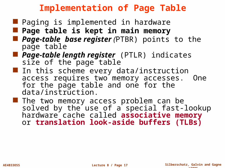
Implementation of Page Table
Paging is implemented in hardware Page table is kept in main memory Page-table base register (PTBR) points to the page
table Page-table length register (PTLR) indicates size of the
page table In this scheme every data/instruction access requires two
memory accesses. One for the page table and one for the data/instruction.
The two memory access problem can be solved by the use of a special fast-lookup hardware cache called associative memory or translation look-aside buffers (TLBs)
Lecture 8 / Page 18 AE4B33OSS Silberschatz, Galvin and Gagne ©2005
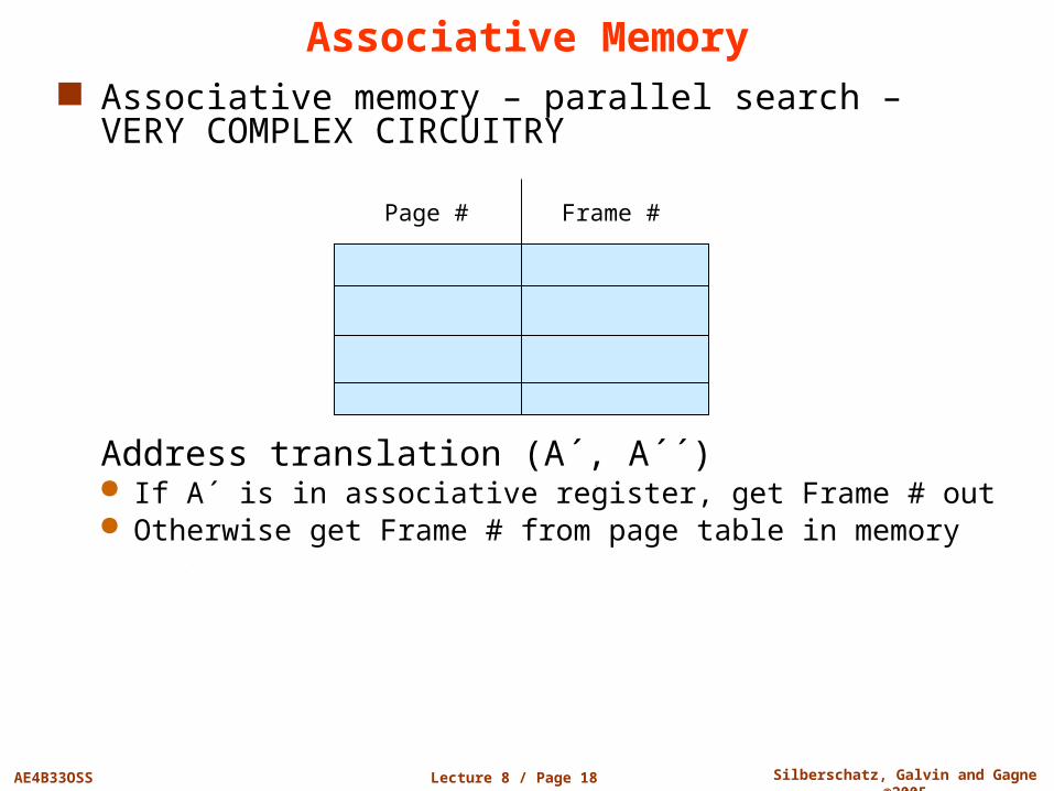
Associative Memory Associative memory – parallel search – VERY
COMPLEX CIRCUITRY
Address translation (A´, A´´) If A´ is in associative register, get Frame # out Otherwise get Frame # from page table in memory
Page # Frame #

Lecture 8 / Page 19 AE4B33OSS Silberschatz, Galvin and Gagne ©2005
Paging Hardware With TLB
CPU
Logical address
Physical address
df
p d
Physical memory
TLB
Page No.
Frame No.
Page found in TLB
(TLB hit)
Page table(PT)
f
p
Lecture 8 / Page 20 AE4B33OSS Silberschatz, Galvin and Gagne ©2005
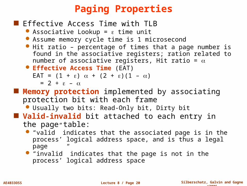
Paging Properties Effective Access Time with TLB
Associative Lookup = time unit Assume memory cycle time is 1 microsecond Hit ratio – percentage of times that a page number is found in
the associative registers; ration related to number of associative registers, Hit ratio =
Effective Access Time (EAT)EAT = (1 + ) + (2 + )(1 – )
= 2 + – Memory protection implemented by associating
protection bit with each frame Usually two bits: Read-Only bit, Dirty bit
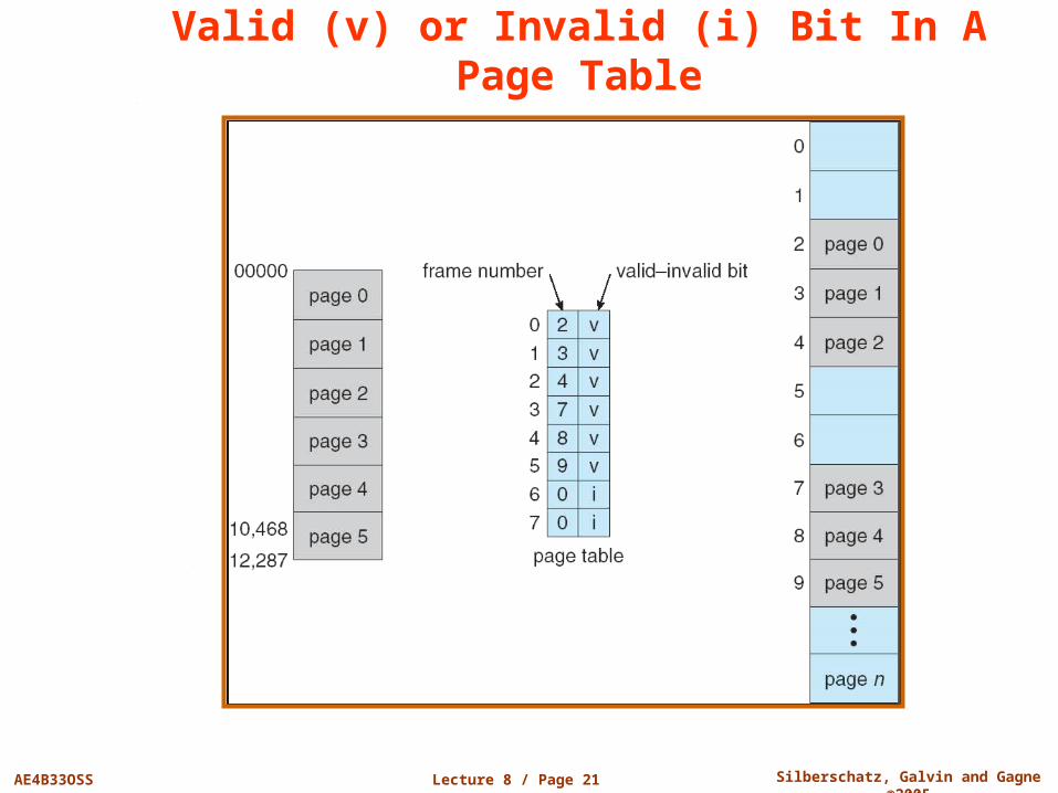
Valid-invalid bit attached to each entry in the page table: “valid” indicates that the associated page is in the process’
logical address space, and is thus a legal page “invalid” indicates that the page is not in the process’ logical
address space
Lecture 8 / Page 21 AE4B33OSS Silberschatz, Galvin and Gagne ©2005
Valid (v) or Invalid (i) Bit In A Page Table
Lecture 8 / Page 22 AE4B33OSS Silberschatz, Galvin and Gagne ©2005
Page Table Structure Hierarchical Paging
Hashed Page Tables
Inverted Page Tables
Lecture 8 / Page 23 AE4B33OSS Silberschatz, Galvin and Gagne ©2005
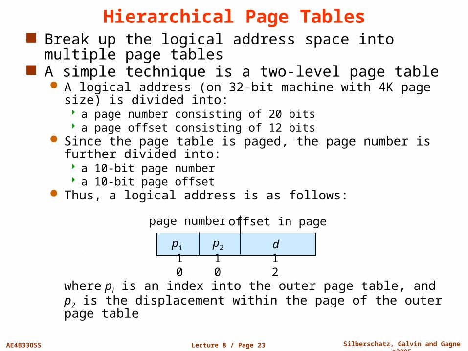
Hierarchical Page Tables Break up the logical address space into multiple page
tables A simple technique is a two-level page table
A logical address (on 32-bit machine with 4K page size) is divided into: a page number consisting of 20 bits a page offset consisting of 12 bits
Since the page table is paged, the page number is further divided into: a 10-bit page number a 10-bit page offset
Thus, a logical address is as follows:
where pi is an index into the outer page table, and p2 is the displacement within the page of the outer page table
page number offset in page
pi p2 d
10 10 12
Lecture 8 / Page 24 AE4B33OSS Silberschatz, Galvin and Gagne ©2005
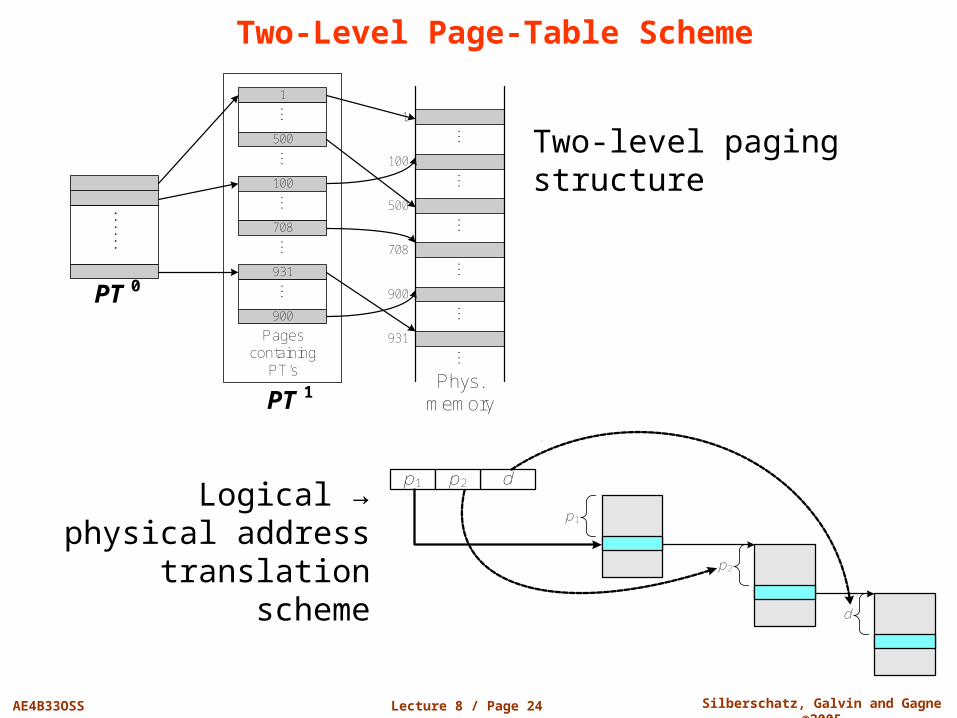
Two-Level Page-Table Scheme
Two-level paging structure
p1 dp2
p1
p2
d
PT 0
......
PT 1
......
1
...
500
100
...
708
931...
900
Pages containing
PT’s
......
......
......
...
1
931
900
708
500
100
Phys. memory
Logical → physical address translation
scheme
Lecture 8 / Page 25 AE4B33OSS Silberschatz, Galvin and Gagne ©2005
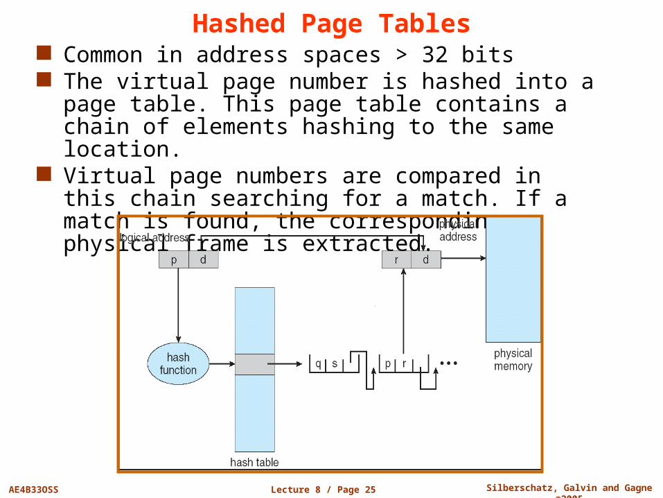
Hashed Page Tables Common in address spaces > 32 bits The virtual page number is hashed into a page table.
This page table contains a chain of elements hashing to the same location.
Virtual page numbers are compared in this chain searching for a match. If a match is found, the corresponding physical frame is extracted.

Lecture 8 / Page 26 AE4B33OSS Silberschatz, Galvin and Gagne ©2005
Inverted Page Table One entry for each real page of memory Entry consists of the virtual address of the page stored in
that real memory location, with information about the process that owns that page
Decreases memory needed to store each page table, but increases time needed to search the table when a page reference occurs
Use hash table to limit the search to one – or at most a few – page-table entries
Lecture 8 / Page 27 AE4B33OSS Silberschatz, Galvin and Gagne ©2005
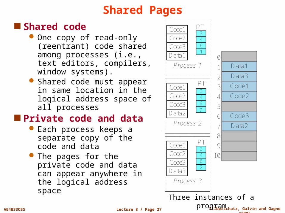
Shared Pages Shared code
One copy of read-only (reentrant) code shared among processes (i.e., text editors, compilers, window systems).
Shared code must appear in same location in the logical address space of all processes
Private code and data Each process keeps a separate
copy of the code and data The pages for the private code
and data can appear anywhere in the logical address space
Three instances of a program
Data1
Data3
Code1
Code2
Code3
Data2
0
1
2
3
4
5
6
7
8
9
10
3461
Code1Code2Code3Data1
PT
Process 1
3467
Code1Code2Code3Data2
PT
Process 2
3462
Code1Code2Code3Data3
PT
Process 3
Lecture 8 / Page 28 AE4B33OSS Silberschatz, Galvin and Gagne ©2005
Segmentation
Memory-management scheme that supports user view of memory
A program is a collection of segments. A segment is a logical unit such as:
main program,procedure, function,method,object,local variables, global variables,common block,stack,symbol table, arrays
Lecture 8 / Page 29 AE4B33OSS Silberschatz, Galvin and Gagne ©2005
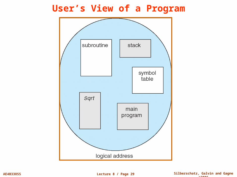
User’s View of a Program
Lecture 8 / Page 30 AE4B33OSS Silberschatz, Galvin and Gagne ©2005
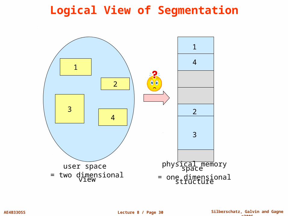
Logical View of Segmentation
1
3
2
4
1
4
2
3
user space = two dimensional view
physical memory space = one dimensional structure
Lecture 8 / Page 31 AE4B33OSS Silberschatz, Galvin and Gagne ©2005
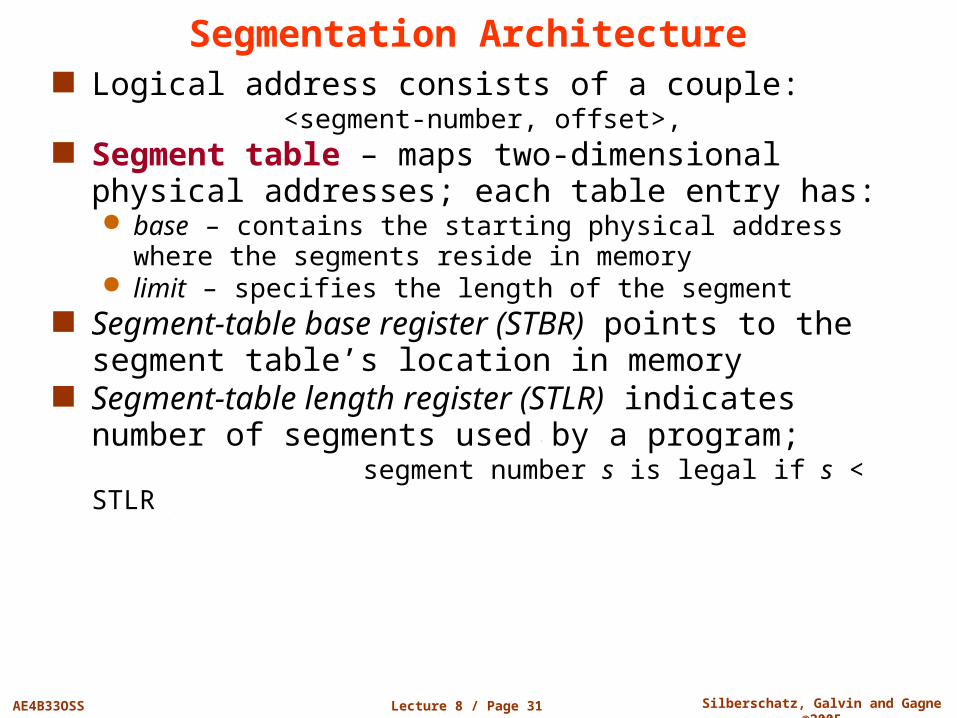
Segmentation Architecture Logical address consists of a couple:
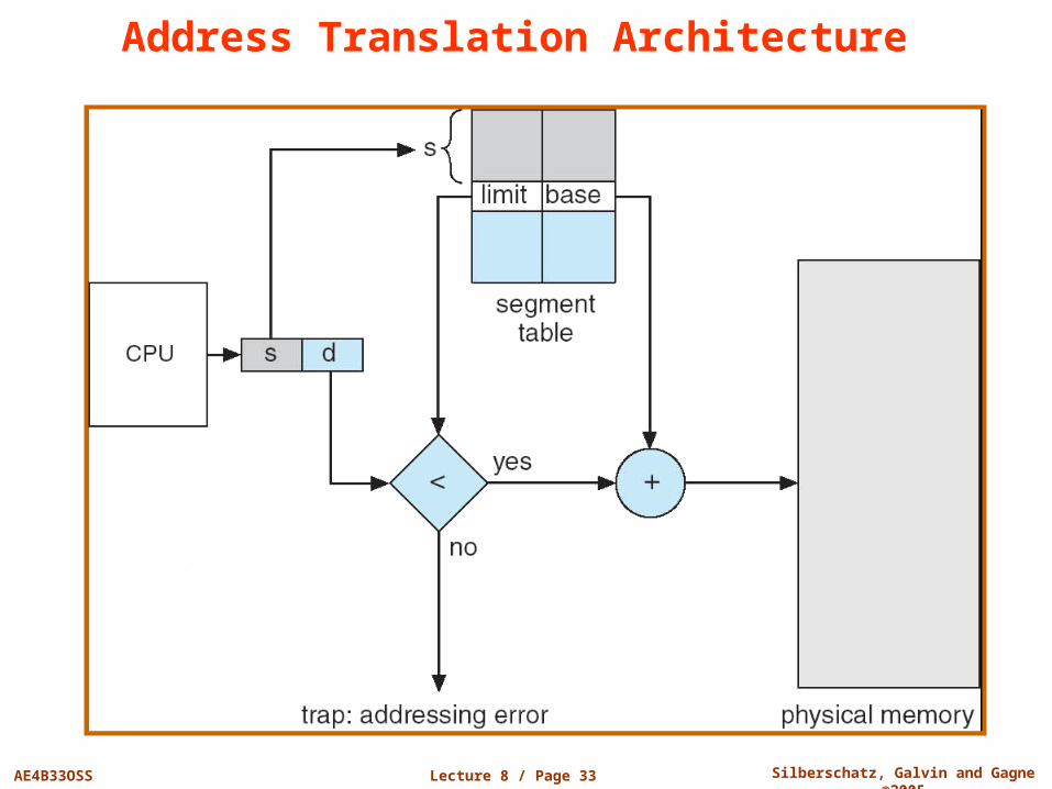
<segment-number, offset>, Segment table – maps two-dimensional physical
addresses; each table entry has: base – contains the starting physical address where the segments
reside in memory limit – specifies the length of the segment
Segment-table base register (STBR) points to the segment table’s location in memory
Segment-table length register (STLR) indicates number of segments used by a program; segment number s is legal if s < STLR
Lecture 8 / Page 32 AE4B33OSS Silberschatz, Galvin and Gagne ©2005
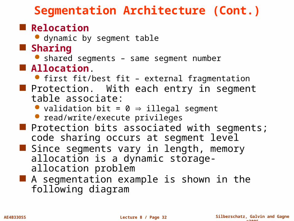
Segmentation Architecture (Cont.) Relocation
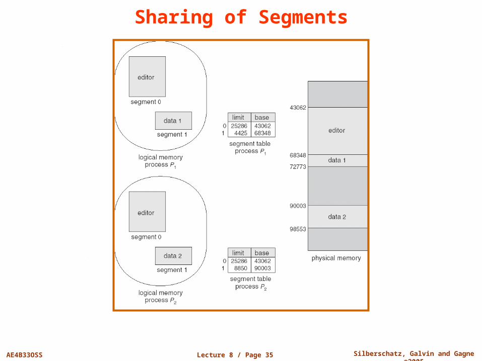
dynamic by segment table Sharing
shared segments – same segment number Allocation.
first fit/best fit – external fragmentation Protection. With each entry in segment table
associate: validation bit = 0 illegal segment read/write/execute privileges
Protection bits associated with segments; code sharing occurs at segment level
Since segments vary in length, memory allocation is a dynamic storage-allocation problem
A segmentation example is shown in the following diagram
Lecture 8 / Page 33 AE4B33OSS Silberschatz, Galvin and Gagne ©2005
Address Translation Architecture
Lecture 8 / Page 34 AE4B33OSS Silberschatz, Galvin and Gagne ©2005
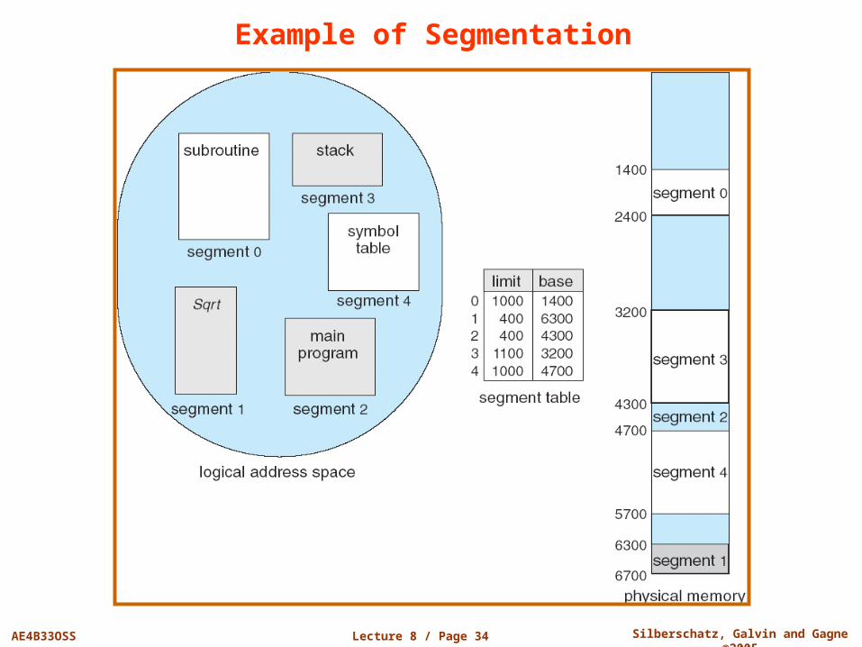
Example of Segmentation
Lecture 8 / Page 35 AE4B33OSS Silberschatz, Galvin and Gagne ©2005
Sharing of Segments
Lecture 8 / Page 36 AE4B33OSS Silberschatz, Galvin and Gagne ©2005
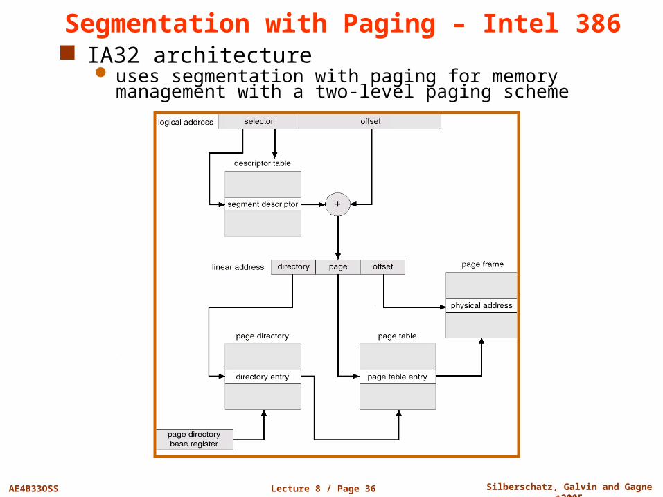
Segmentation with Paging – Intel 386 IA32 architecture
uses segmentation with paging for memory management with a two-level paging scheme
Lecture 8 / Page 37 AE4B33OSS Silberschatz, Galvin and Gagne ©2005
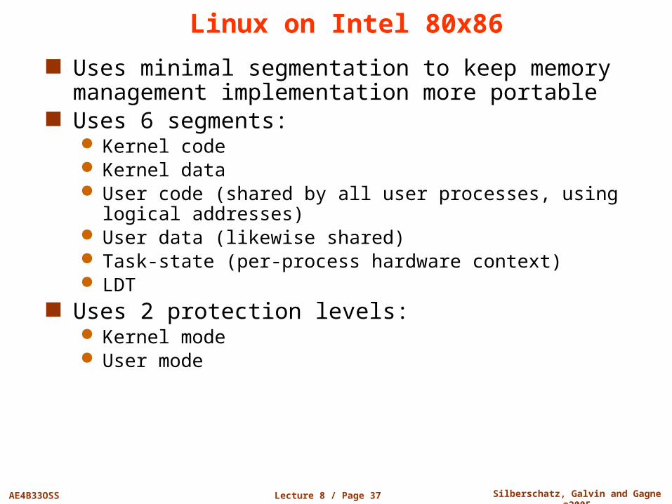
Linux on Intel 80x86
Uses minimal segmentation to keep memory management implementation more portable
Uses 6 segments: Kernel code Kernel data User code (shared by all user processes, using logical
addresses) User data (likewise shared) Task-state (per-process hardware context) LDT
Uses 2 protection levels: Kernel mode User mode

End of Lecture 8
Questions?