Embed Size (px)
Citation preview
Mauricio Lopes – FNAL
Lecture 7: Magnet Fabrication
Introduction • Conventional magnet performance and quality is dominated by the
core design and fabrication.
• Field quality depends not only on the pole design, but is highly dependent on the mechanical fabrication and assembly tolerances. Design of magnets, including the core assembly practices, often determine the quality of the final product.
• Magnet to magnet reproducibility require that the iron properties among magnets be uniform.
• The boundaries surrounding magnet design and fabrication go beyond satisfying the physics requirements. Once the magnets have been fabricated and tested, they must be installed and aligned. Consideration of the installation and alignment requirements and procedures must be built into the magnet design. In order to install and align magnets, the support system and the system of fiducialization must be built into the initial design of the magnets. The cost of retrofit is high.
2

Solid Cores or Laminated Cores
The choice of solid or laminated cores has historically been associated with whether the magnetic field is time varying or steady state.
Insulated laminations are always used for time varying field magnets in order to reduce or eliminate eddy current effects.
Ferrite might be used for fast, low field magnet cores.
Presently, many steady state magnets are assembled with laminated cores.
3
Economics
4
• Solid iron yokes are often used in simple, flat pole contour magnets.
• The cost of laminated cores are often less if the quantity of magnets is large.
• Die set costs are approximately 50 k$.
• Costs of laminations is about $1/lamination.
• Core assembly time is about 2 to 4 m-days/core.
• For complicated yoke shapes, quadrupoles, sextupoles and gradient magnets, the cost of machining solid cores can be prohibitive.

Reproducibility and Symmetry
5
• The following discussion will assume the use of laminated rather than solid core magnets. Most modern accelerators, even storage rings whose energy are not ramped, use laminated magnets. The reason for this is more than just the economics of fabrication. The driving motivation for using laminations to assemble magnet cores is magnet to magnet reproducibility and symmetry.
• Dipole magnets, both flat field and gradient, are usually connected in power supply series. Therefore, it is essential that the magnet be identical among all the magnets at the same current.
• Families of quadrupoles and sextupoles are often connected in series.
6
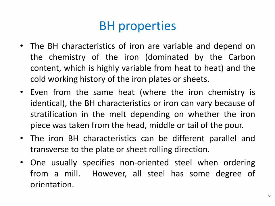
• The BH characteristics of iron are variable and depend on the chemistry of the iron (dominated by the Carbon content, which is highly variable from heat to heat) and the cold working history of the iron plates or sheets.
• Even from the same heat (where the iron chemistry is identical), the BH characteristics or iron can vary because of stratification in the melt depending on whether the iron piece was taken from the head, middle or tail of the pour.
• The iron BH characteristics can be different parallel and transverse to the plate or sheet rolling direction.
• One usually specifies non-oriented steel when ordering from a mill. However, all steel has some degree of orientation.
BH properties

Die Sets and Lamination Stamping
7
• The design of the lamination should incorporate several considerations regarding material and die wear.
• The maximum size of the lamination should consider the rolling width of the sheet. Sheets are normally slit from master coils, and the sheets slit from the edges of the coils often are tapered near the edge.
• The lamination design should avoid sharp internal and external corners. The punch and die pieces have excessive wear at these features. If the design incorporates sharp corners, the die fabricator will often recommend design changes.
• Tooling should be thick enough to undergo several sharpening procedures during the production stamping.

Lamination Shuffling
8
• Shuffling is often used to enhance magnet to magnet reproducibility and symmetry.
• The laminations are stacked on pallets for each magnet segment as they arrive. This distributes the BH iron variation among each magnet and each segment of each magnet.
• It is not necessary to wait until all the laminations have been stamped since they can be distributed on pallets as they arrive.
• Laminations may be stamped with orientation along and transverse to the rolling direction in order to cancel any directional variation of BH behavior.
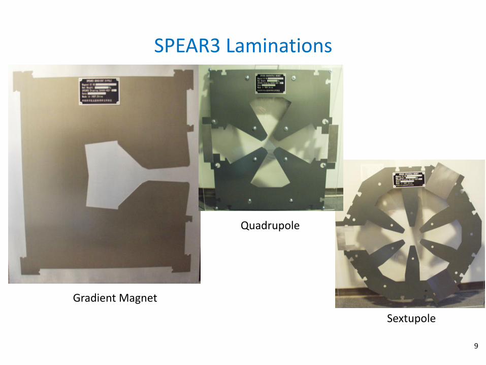
SPEAR3 Laminations
9
Gradient Magnet
Quadrupole
Sextupole

Core Stacking and Compression
10
Cores stacked from laminations exhibit certain elastic characteristics. These characteristics are displayed as an effective elastic modulus of the stack, which are usually manifest themselves into three stages.
– Removal of space between the laminations
– Flattening of the lamination warps
–Metal to metal compression
psi)in expressed(usually Strain
Pressure
L
LArea
Force
E
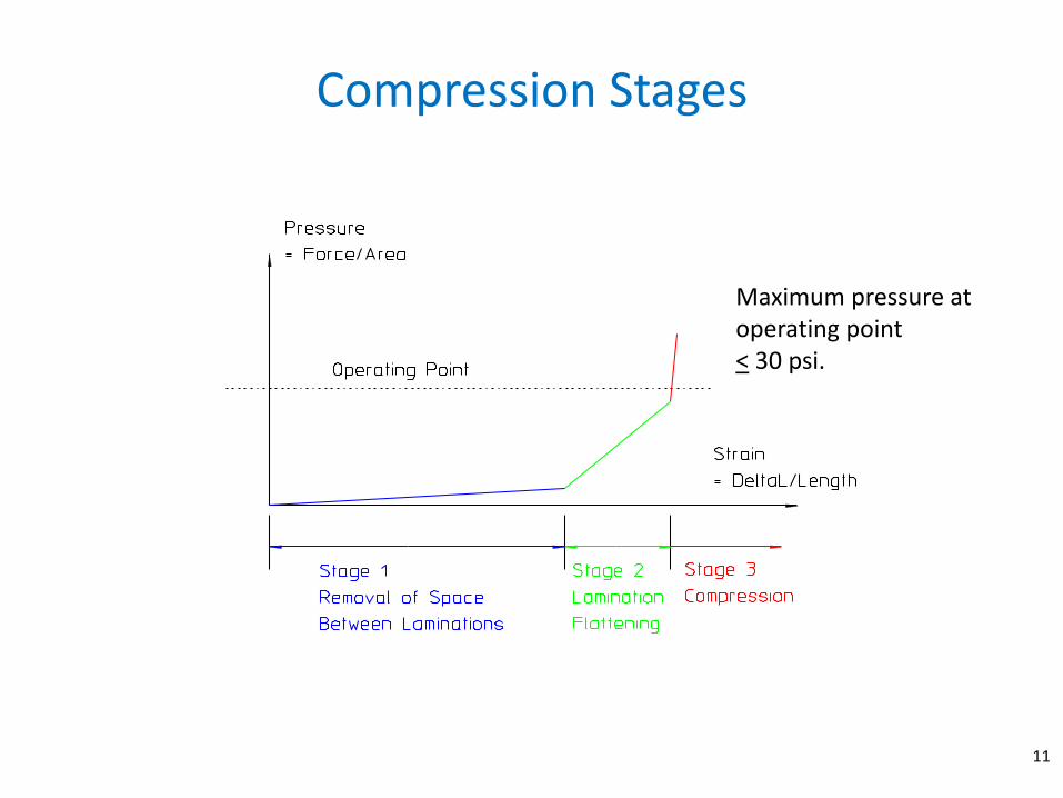
Compression Stages
Maximum pressure at operating point < 30 psi.
11
Core Assembly Techniques
12
• Different techniques are used to assemble cores.
–Welding
– Gluing
–Mechanical Frame Technique
• Welding and gluing are standard assembly techniques.
• The mechanical frame technique is way of assembling a precise mechanical core which avoids the distortion due to welding and can also be used for fairly long cores.
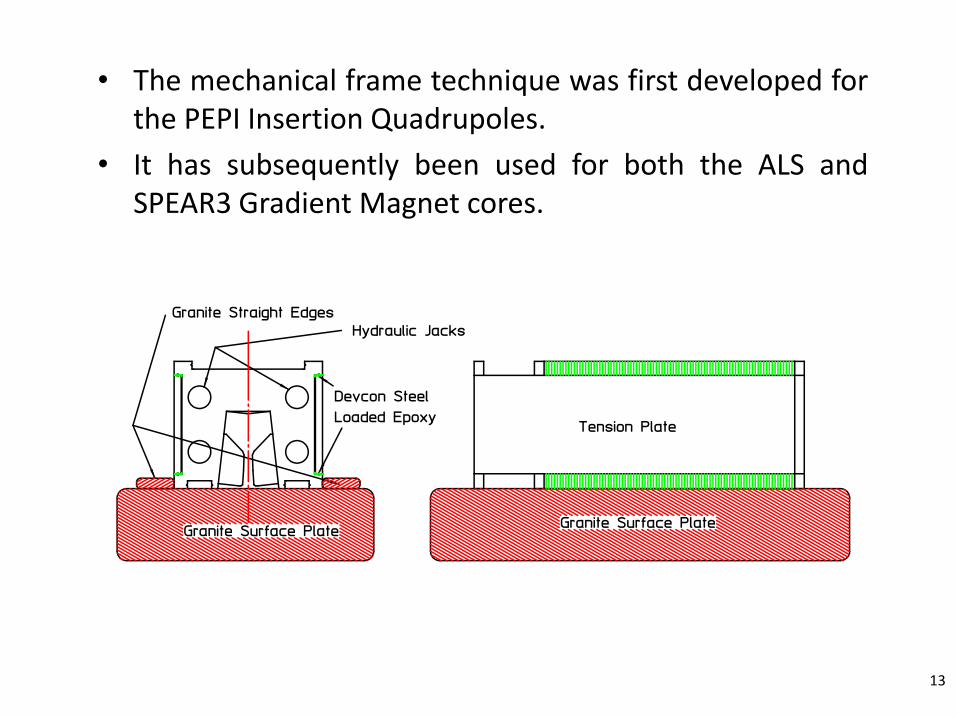
• The mechanical frame technique was first developed for the PEPI Insertion Quadrupoles.
• It has subsequently been used for both the ALS and SPEAR3 Gradient Magnet cores.
13
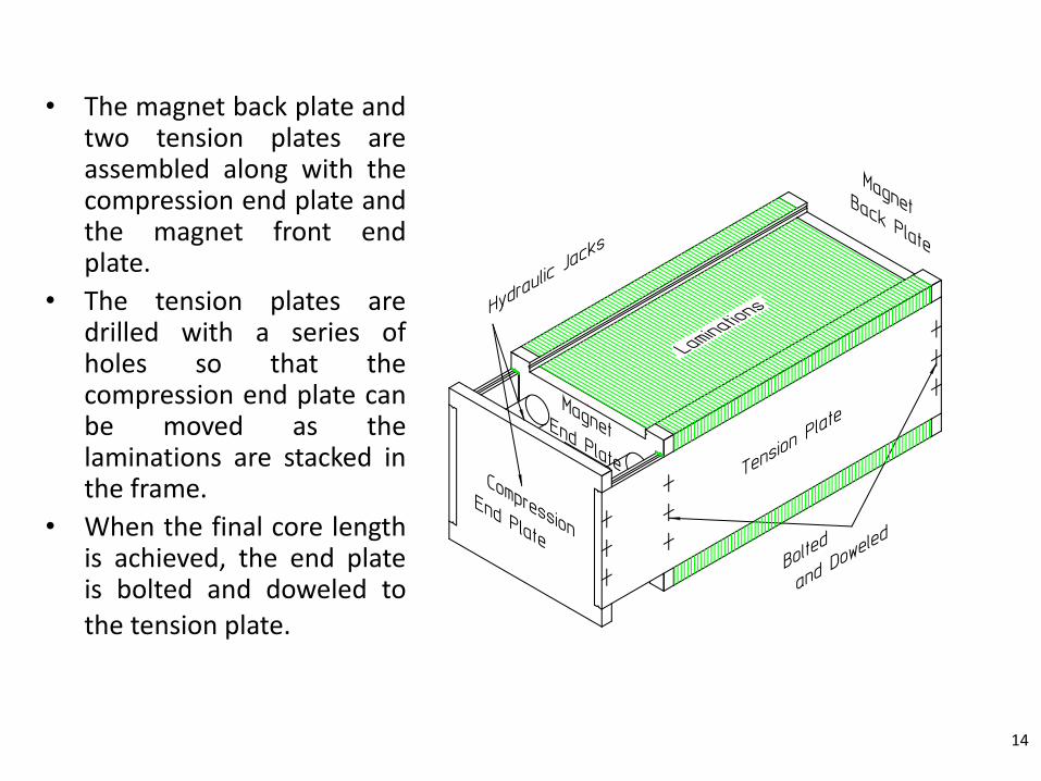
• The magnet back plate and two tension plates are assembled along with the compression end plate and the magnet front end plate.
• The tension plates are drilled with a series of holes so that the compression end plate can be moved as the laminations are stacked in the frame.
• When the final core length is achieved, the end plate is bolted and doweled to the tension plate.
14
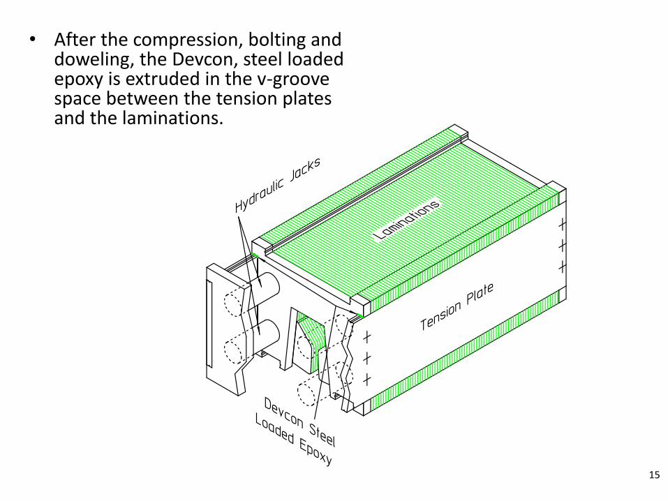
• After the compression, bolting and doweling, the Devcon, steel loaded epoxy is extruded in the v-groove space between the tension plates and the laminations.
15
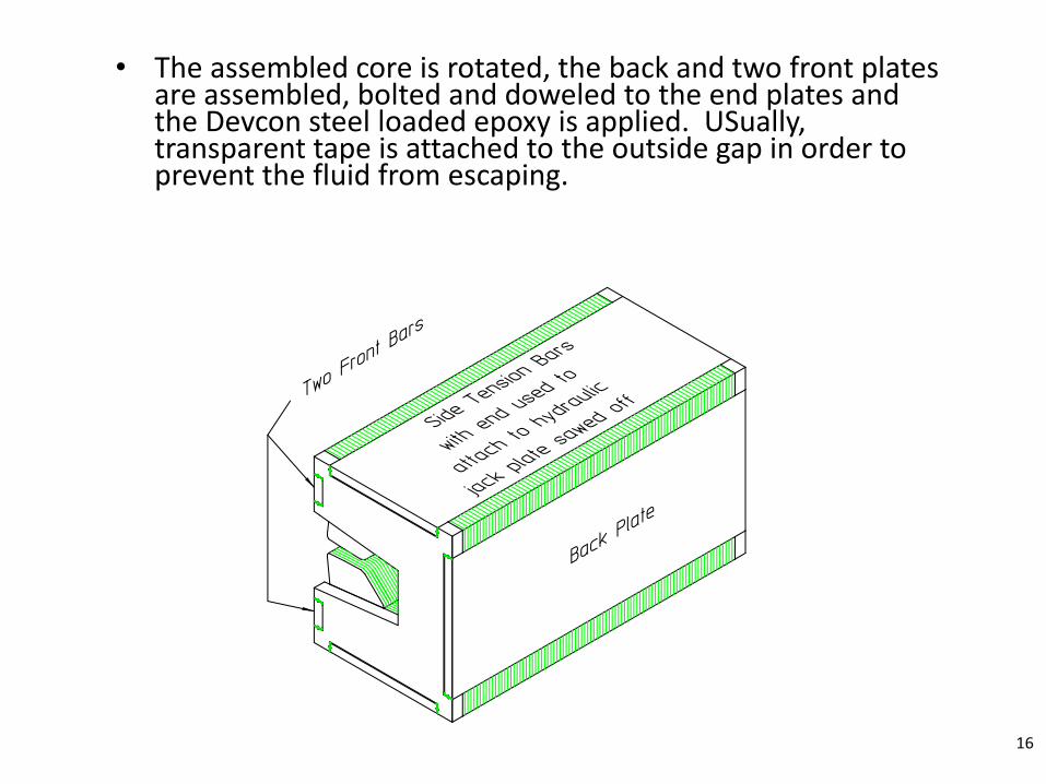
• The assembled core is rotated, the back and two front plates are assembled, bolted and doweled to the end plates and the Devcon steel loaded epoxy is applied. USually, transparent tape is attached to the outside gap in order to prevent the fluid from escaping.
16

• The steel loaded epoxy comes in a variety of curing times and viscosities. Normally, it is applied with a pressure gun using a long tube to reach into the v-groove gap. Some experimentation is often needed in order to find the best technique for applying this material.
17

• The magnet cores fabricated in this manner result in a surprisingly robust structure. Shown below is one of the 1.45 meter long gradient magnets that accidentally fell off of a truck while being transported to the raft assembly area.
18

• While the coil and assembly suffered major injury, the core was undamaged.
• New coils were assembled and the magnet was installed in the SPEAR3 ring.
19
Magnet Fiducialization
20
• Magnet alignment specifications for accelerators and beam transport lines typically call for < +250mm precision transversely and vertically and < +500mm longitudinally.
• Rotational tolerances are typically < +0.2 mrad in roll, pitch and yaw.
• The centers of magnets are normally not accessible in accelerators or beam-lines because of the presence of evacuated beam-tubes. Therefore, it is necessary to know the precise positions of external features which can be measured and aligned with respect to the accelerator/beamline coordinate system. These features are called fiducials and the measurement and/or identification of these features with respect to the local magnet coordinate system is called fiducialization.
21
• There are two styles of fiducialization, both used extensively to align magnets. – Generic fiducialization (USed for PEPII)
• Generic fiducialization relies on design features of the magnet. Thus, the coordinates of the fiducial features are assumed to be identical among all magnets of the same design family.
• This method relies on the precise and reproducible positioning of fiducial targets on all magnets.
– Pedigreed fiducialization (USed for ALS and SPEAR3) • Pedigreed fiducialization measures the coordinates of
fiducial features on each individual magnet. • It does not rely on precision or reproducibility in the
positioning of targets. • It requires that a large database be maintained with
all the coordinates of each magnet.

• Fiducialization requires one to adopt and use the language of metrology. In this language, three separate features must be defined in three dimensional geometry.
– The principal plane
• The principal plane is the plane containing two of the orthogonal coordinate axes. In magnets, this is usually the z (longitudinal) and x (transverse) axes.
– The principal line
• The principal line is a line in the principal plane which defines a direction. In magnets, this is usually the z (longitudinal) direction.
– The principal point
• The principal point is a point on the principal line and defines the origin of the axes. This is usually the longitudinal center of the magnet.
22
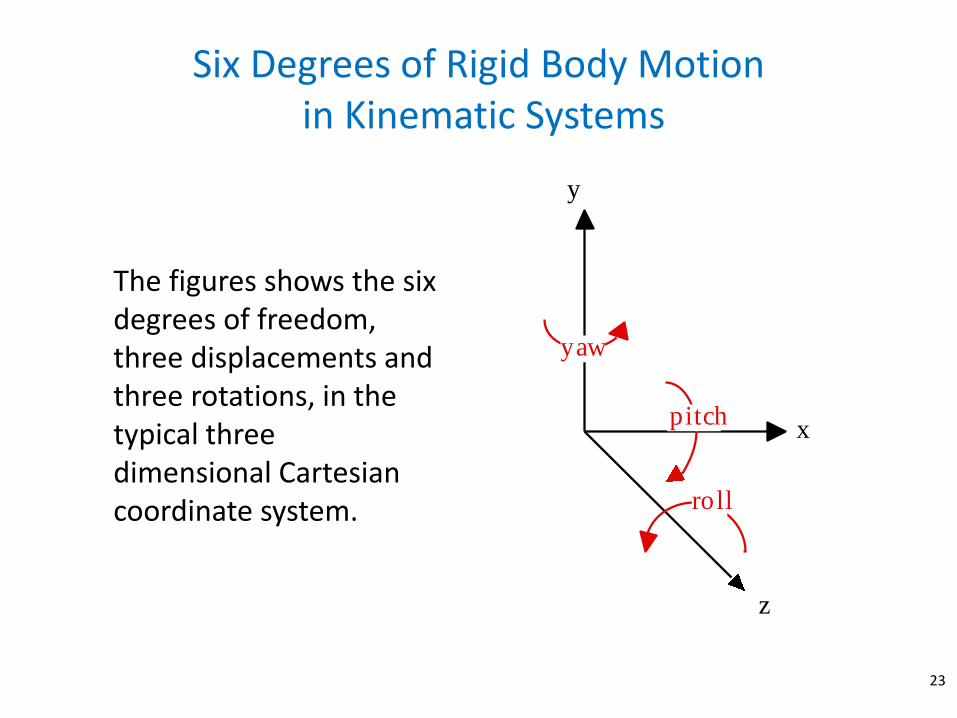
Six Degrees of Rigid Body Motion in Kinematic Systems
23
The figures shows the six degrees of freedom, three displacements and three rotations, in the typical three dimensional Cartesian coordinate system.
x
y
z
pitch
roll
yaw
Support and Alignment
24
• A true kinematic support system must have at least and at most six linearly independent supports.
• Two examples of kinematic support systems are the six strut support and the three block support systems. The advantages and disadvantages of each system are; – Six strut advantage – quickly and easily adjustable.
– Six strut disadvantage – soft structure, therefore low natural vibration frequencies.
– Three block advantage – high stiffness leading to high natural frequencies. This is important for photon beam stability in light source accelerators.
– Three block disadvantage – more difficult to adjust requiring more time.
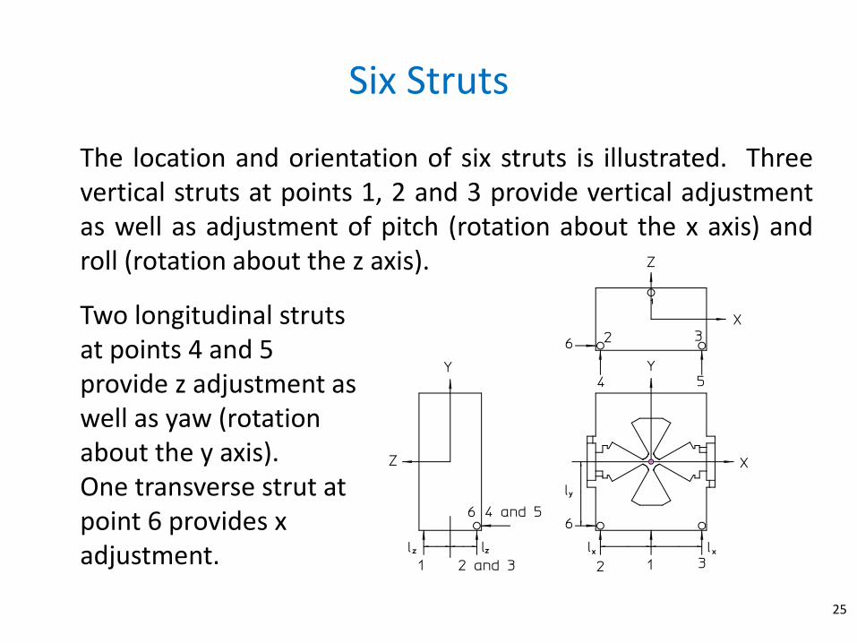
Six Struts
25
The location and orientation of six struts is illustrated. Three vertical struts at points 1, 2 and 3 provide vertical adjustment as well as adjustment of pitch (rotation about the x axis) and roll (rotation about the z axis).
Two longitudinal struts at points 4 and 5 provide z adjustment as well as yaw (rotation about the y axis). One transverse strut at point 6 provides x adjustment.

Three Block Support
26
There are three support blocks. Each block has buttons which can be machined to a desired thickness.
– Corner block has x, y and z buttons.
– Edge block has y and z buttons.
– Flat block has y button.
Coils fabrication
27
• Whether coils are made in house or by vendors, certain quality standards must be met to ensure that magnets will operate as required.
• Specifications have been developed over the years to ensure magnet coil quality. These include material and fabrication requirements as well as performance tests.
• Rules governing electrical safety differ with different regions. The practices to ensure that magnet systems satisfy state and federal electrical safety requirements are reviewed.
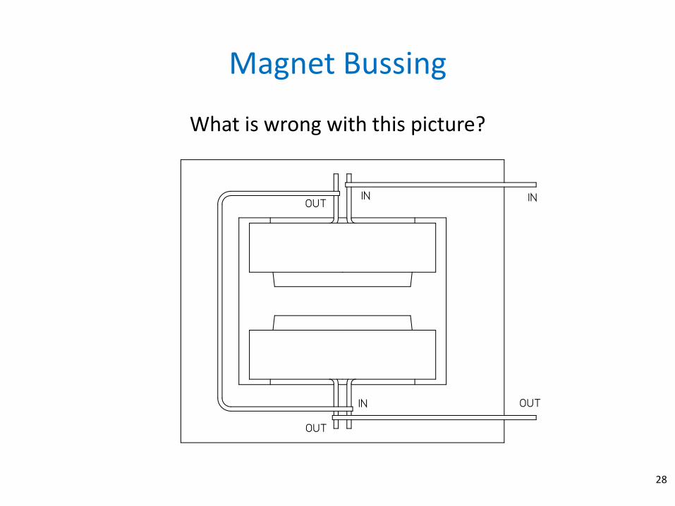
Magnet Bussing
28
What is wrong with this picture?
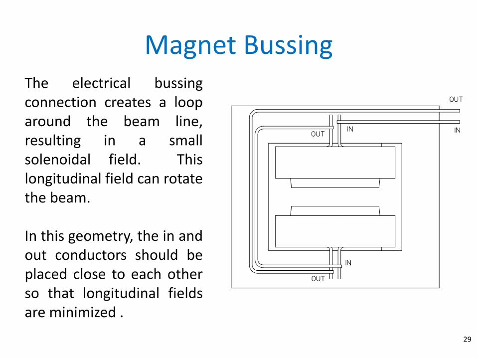
The electrical bussing connection creates a loop around the beam line, resulting in a small solenoidal field. This longitudinal field can rotate the beam. In this geometry, the in and out conductors should be placed close to each other so that longitudinal fields are minimized .
Magnet Bussing
29

Quadrupole and Sextupole Bussing
30
The correct quadrupole and sextupole bussing scheme is shown. Again, it is recommended that the conductors be placed close to each other.
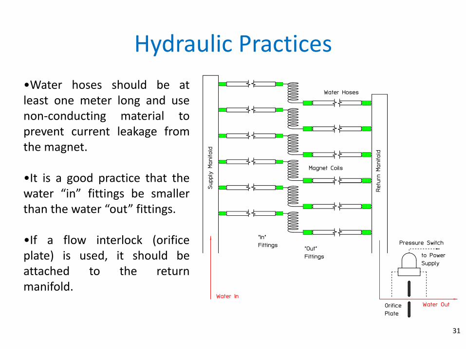
Hydraulic Practices
31
•Water hoses should be at least one meter long and use non-conducting material to prevent current leakage from the magnet.
•It is a good practice that the water “in” fittings be smaller than the water “out” fittings.
•If a flow interlock (orifice plate) is used, it should be attached to the return manifold.
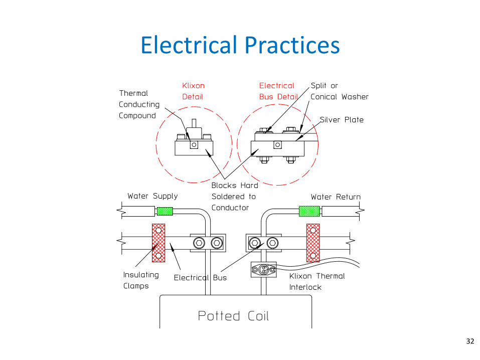
Electrical Practices
32
Klixon Thermal Interlock
33
• The Klixon thermal interlock system is a switch which opens when it senses a temperature higher than its set-point. The thermal interlock system is connected to the power supply and is designed to shut down power if a coil temperature exceeds the interlock set-point.
– The normal set-point of Klixons is about 89o C. It will generally reset at about 70o C, although a buyer can request special temperature values for these interlocks.
– One thermal interlock is installed on each water circuit. If a coils has more than one water circuit, multiple interlocks are installed to protect that coil.
– All the interlocks on one magnet are connected in series.
34
• Interlocks for magnets in power supply series strings may or may not be connected in series.
• If too many elements are connected in a series string, it is difficult to identify the particular magnet or circuit in that magnet. This becomes especially troublesome if the Klixon suffers intermittent failure.
• The Klixon is preferably mounted on the water return lead of the coil.
• The Klixon is always mounted on the current carrying portion of the conductor (inside the electrical connection bus.
• The Klixon is mounted to a block hard-soldered to the conductor. The interface between the Klixon and the mounting block is coated with a thermal conducting paste.
Internal Electrical Bussing
35
• Practices for the internal electrical connection separate magnet coils are used to ensure safe and reliable magnet operation.
• Blocks to the connection of busses to the separate coils are hard soldered to the conductor.
• The busses are generally air cooled and therefore are sized so that the maximum current density is < 1.5 A/mm2.
• Since the busses are significantly heavier than the coil conductor, with current density < 10 A/mm2, insulating support blocks (usually epoxy fiberglass) are attached to the core to support the busses and protect the coil conductor from damage. No mechanical load should be carried by coil leads.
• The interfaces between the busses and the coil blocks are either silver plated or coated with an electrically conducting compound.
• Conical washers are used under flat washers and either the bolt head or the nut.
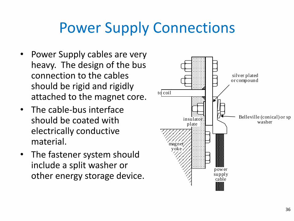
Power Supply Connections
36
• Power Supply cables are very heavy. The design of the bus connection to the cables should be rigid and rigidly attached to the magnet core.
• The cable-bus interface should be coated with electrically conductive material.
• The fastener system should include a split washer or other energy storage device.
to coil
insulator plate
magnet yoke
Belleville (conical) or split washer
power supply cable
silver plated or compound
Lead Insulation and Coil Covers
37
• Coil covers or careful coil taping is required to prevent direct personnel contact with any magnet conductor or bus connection under the following conditions:
– IV > 150 V-Amperes or I > 30 Amps or V > 130 Volts or when the magnet stored energy is > 5 joules.
• Coil covers are recommended for all magnets regardless of their operating condition since it is difficult to audit safety practices when many different magnets are installed in the typical beamline. The hot end of the coil cooling tubes (the fittings) must also be enclosed in the cover.
• Safety rules require that any removable section of a coil cover must be attached by at least four screws.
Electrical Grounding
38
• Safety rules require all non-electrically powered accelerator components to be electrically grounded.
• Magnet cores are often assembled from laminations which may or may not be electrically connected to each other or to the core structure.
• As part of the core assembly procedure, a single weld bead is often specified, electrically connecting all magnet laminations together.
• A single connection point is provided to attach a metal strap grounding the magnet core to the support girder or other ground point.
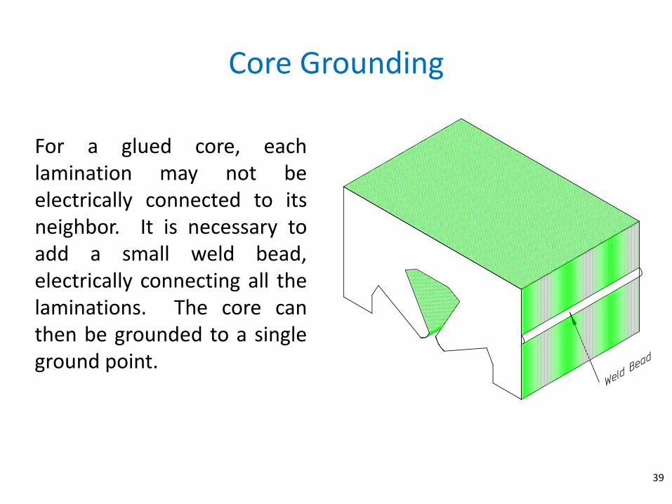
Core Grounding
39
For a glued core, each lamination may not be electrically connected to its neighbor. It is necessary to add a small weld bead, electrically connecting all the laminations. The core can then be grounded to a single ground point.

Coil Fabrication Specifications
40
• The specification should require that coils are wound in a clean environment and not in a shop environment where metal chips are present. If metal chips are embedded in the potted coils, they can cause intermittent shorts that are difficult to detect and can be extremely troublesome.
• A single water circuit in a coil assembly should be wound from a single continuous length of conductor. Splices “buried” within the potted insulation should not be allowed.
• Hollow aluminum conductors should be tested for leaks prior to winding. Aluminum conductors are usually assembled from four separate pieces which results in a conductor with four seams which run the length of the conductor. Leaks can occur in this type of fabrication. Copper conductor are extruded from a single piece of copper in a identical manner that small diameter tubes are fabricated. Therefore, one seldom encounters leaks in hollow copper conductor.
– USually, the leak test is a pneumatic test where the cooling channel is pressurized and the pressure monitored for some time (usually several hours).
• A ball test is specified for a conductor before it is wrapped into a magnet coil. This test consists of using high pressure air to blow a ball, no more than 80% of the diameter of the conductor hole, through the conductor water flow passage in order to ensure no blockage or collapsed passages.
– For long conductor lengths, or small cooling hole diameter, this test is omitted. (Pneumatic pressure drops can be very high during this test.)
– If the conductor vendor supplies long hollow conductor which is spliced, the location(s) of a splice should be clearly marked so that the continuity of the water cooling passage can be ensured.
41

Summary
42
• This lecture highlighted the main issues of yoke and coil fabrications. • Physics specifications for accelerator magnets require excitation reproducibility
and a spectrum of small amplitude integrated multipole errors. These field properties are dominated by the properties of the fabricated magnet yokes. Good magnet performance require the iron properties of the magnets to by symmetric and reproducible.
• One can select the coil geometry which optimize the purchase and operation of power supplies and power distribution systems and satisfy hydraulic cooling constraints.
• A number of measure have to be taken in order to protect the magnet, the power supply, the facility and personnel from eventual failures .
Next…
43
Simulations