Embed Size (px)
Citation preview

GOLD PLATINGOF CRITICAL COMPONENTS
FOR SPACE APPLICATIONS:
CHALLENGES AND SOLUTIONS
Indira Rajagopal, K.S. Rajam er S.R. Rajagopalan
Materials Science DivisionNational Aeronautical Laboratory
Bangalore 560017India
Ensuring the maximum reliability of the gold plating on
lightweight alloys used in space applications is a difficult and
challenging task. In this article, the authors describe the
processes that they have found to meet requirements.
Aluminium, magnesium, titanium and their alloysare increasingly used as the lightweight structuralmaterials in aircraft and space applications, where light-ness is always at a premium. To meet the end require-ments (e.g., for improving corrosion and wear resis-tance, for increasing surface conductivity, for thermalcontrol, etc.) surface coatings are applied to modifythe surface properties.
Unfortunately, plating on these lightweight struc-tural materials is difficult. These metals and alloysbelong to the group of difficult-to-plate materials. Thebasic problem stems from their high electrochemicalpotential in aqueous solution and their consequenthigh reactivity in air even at room temperature. As aresult, they are always covered with a tenacious surface
oxide film which prevents metal-to-metal bonding,thus leading to poor adhesion.
For space applications, the reliability of theplating should be 100 %. This means that the adhe-sion should be excellent and high quality depositsshould be produced. Defective plating is unaccept-able as it seriously affects the launching and/or func-tioning of the spacecraft. Stripping the defectivedeposits without damaging the sensitive compo-nents also poses problems. Hence it is mandatoryto control deposit characteristics with very high re-liability by surface preparation procedures, bycareful selection and control of bath compositionand operating conditions, and by post-plating han-dling procedures.
Gold Bull., 1992, 25 (2) 55

Figure 1:
Waveguide in 6061 aluminium alloy
Gold coatings are always the preferred choice inthe space programmes. Gold's high conductivity, stablesurface resistivity, tarnish resistance, and resistance tochemical corrosion and high temperature oxidationcontribute to its high reliability in performance in thespace environment.
At the National Aeronautical Laboratory, Banga-lore, space quality gold plating on critical componentsfabricated from aluminium and magnesium alloys andfrom stainless steel has been developed and these com-ponents have been used successfully in Indian spaceprogrammes. Work of the authors in this field isbriefly summarised in this article.
GOLD PLATING ON 6061ALUMINIUM ALLOY WAVEGUIDES
Figures 1 to 3 show waveguides made out of 6061aluminium alloy (Al-Mg-Cu-Cr alloy). These com-ponents were to be gold plated uniformly to a thick-
ness of 5 tun to impart surface conductivity. Goldplating of these components posed the followingchallenges:
Obtaining an adherent coating on 6061 alu-minium alloy, which belongs to the group of diffi-cult-to-plate materials.Obtaining a very uniform coating on such complexshaped components.Obtaining first quality gold deposits to meet thespace qualification requirements.
Obtaining an adherent coating on 6061 Al alloy isdifficult for the following reasons:
The surface is covered with a tenacious, imperviousoxide film. This film, after removal by normalcleaning processes, is rapidly formed again andthereby hinders metal-to-metal bonding, leadingto non-adherent or poorly adherent deposition.The alloy contains 1 % Mg, 0.25 % Cu and 0.25 %Cr besides aluminium. These alloying elementsmay appear in several different forms - as a solidsolution in the aluminium lattice, as micro parti-cles of the elements themselves or as particles ofintermetallic compounds formed by combina-tion with aluminium or other alloying elements.Such microstructural and compositional hetero-
geneity causes non-uniform electro-chemical behaviour.Hence, to achieve excellent adhesion,the oxide film should be removed andreplaced by an adherent and more re-ceptive film. Such a film should be ca-pable of forming on a surface with anon-uniform electrochemical reactivityand converting it to a surface of uniformactivity. This is accomplished by properchoice of the preplating schedule.
The following process sequencesproved to be the best for achieving excel-lent adhesion.
I. Degreasing
The components were degreased withtrichloroethylene/acetone. To effectivelyclean the bores and internal surfaces ofthe components, ultrasonic agitationwas employed.
56
Gold Bull., 1992, 25 (2)

Figure 3:Waveguide in 6061 aluminium alloy]
Figure 2:
Waveguide in 6061 aluminium alloy
4. Etching
To achieve best adhesion in the sub-sequent deposition processes, the surfaceof the components are subjected to mildetching, which produces uniform 'keyingin' points. Etchants should be so chosenthat they produce a uniform micro-rough-ened surface. The composition of some of
the acid etchants tried and found to be satisfactory aregiven in Table 1.
a hot solution of phosphoric acid andchromic acid mixture for five minutes:
H3PO4 = 30 m1/1Cr03 = 25 g/1
Temperature = 95 °CTime = 5 minutes
The oxide film is completely removed inthis step. The main advantage of usingthis solution is that it removes only theoxide and there is practically no attack onthe aluminium alloy substrate.
2. Alkaline Cleaning
The components were cathodicallycleaned in a mild alkaline cleaner (Ta-
ble 3a, p. 66). At this stage, after thoroughwashing, the components were in a per-fectly clean condition for further processing.
3. Deoxidising
Generally, after cleaning, the compo-nents are subjected to etching treatment.Though the aluminium alloy surface isfree from dirt and grease, the surface maybe covered with a thin natural film orthick tenacious oxide film formed dur-ing the fabrication of the parts or as aresult of chemical or thermal processes.This oxide film may result in non-uni-form etching. Hence to facilitate uni-form etching we found that it is essentialto introduce a deoxidising step, whereinthe oxide film is uniformly removed. Forthis purpose the components are treated in
Gold Bull., 1992, 25 (2)
57

5. Smut Removal
After etching, the surface of the components may becontaminated by non-adherent smut. This is removedby immersion in 50 % nitric acid for 15 to 30 seconds.
6. Double Zincating
The components are then zincated in a modifieddilute zincating solution of the following composi-tion at room temperature:
ZnO = 20 g/1NaOH = 120 g/1
Rochelle salt = 50 g/1FeCl3 • 6H20 = 1.5 g/1
Double zincating provided a uniform thin immersionzinc coating, which had better receptivity than singlezincated film.
Table 1:Etchants for 6061 aluminium alloys
7. Electroless Nickel (EN) Bond Coating
After zincating, the common practice is to give a flashcoating of copper from a special bath of Rochellecopper cyanide, which does not attack zinc when thezincated parts are plunged into the bath with thecurrent on. Instead of copper strike we used elec-troless nickel bond coating from a special purpose
EN bath. This is a crucial step which dictates theadhesion of subsequent gold plating. Since the zinccoating thickness is very small, the reaction in theelectroless plating bath should not be vigorous.(This will lead to the corrosion of the underlyingaluminium alloy resulting in spongy deposition.)Out of the several formulations tried, the bathbased on citrate-fluoride was found to be the best.The bath composition and operating conditionsare given in Table 3b (p. 66).This bath when used at room temperature produces auniform and extremely adherent coating of electrolessnickel. EN is built up to a thickness of about 2 uni andserves the same purpose as the copper strike. Opera-tion of the bath at room temperature is beneficial sincethe problems associated with high temperature proc-esses are avoided. Replacement of the copper strike byelectroless nickel plating was advantageous because thelatter produced a uniform deposit inside bores and oncomponents of complex shape.
The above preplating schedule has to be care-fully followed to achieve excellent adhesion. Fig-sures 4 and 5 show clearly the vital role played bythe preplating schedule. Figures 4a and 5a (leftsamples) show samples of 6061 Al alloy goldplated after a thorough precleaning schedule. Nodelamination or peeling occurs. The gold plated sam-ples were found to pass all the tests - namely bending,drilling, cutting and heat-quenching tests and a testof thermal cycling under high vacuum conditions. InFigures 4b and 5b (right samples), the gold platedsamples show respectively blistering and delamina-tion, due to improper pretreatment.
8. Gold Plating
The other two problems, namely achieving uniformcoating on complex shapes and gold deposit charac-teristics to suit space applications, are now consideredin detail.
Achieving uniform deposition on complex shapesbefore the gold plating stage was not a problem sinceall the processes are of the immersion type. In thegold plating stage, uniformity is the prime consid-eration. To plate internal surfaces of the components,an internal anode arrangement is needed. A thin stain-less steel anode plated with gold (2.5 ttm) was insu-
58
Gold Bull., 1992, 25 (2)

Figures 4 & 5:6061 aluminium alloy samples after gold platingleft: gold plating after a thorough pre-cleaningright: gold plating after improper pretreatment
Gold Bull, 1992, 25 (2) 5S

lated with a loosely braided glass fibre cloth and usedto effectively plate the inner side. The flexible braidprevented short circuiting and burning while permit-ting flow of electrolytic current. Forced circulation ofthe electrolyte by means of a pump was used to overcomethe problems due to depletion of gold in the electrolyte
Figure 6:Exemple of a typical communication package
made out of RZ 5 magnesium alloy
inside the holes. Frequent to and fro motion of theanode was used to further assist the supply of freshelectrolyte and hence uniformity of deposition.
The gold plating bath formulation was selected tosuit the space qualification requirements according towhich the gold deposit
- should be of high purity, i.e. 99.9 cYo- should have a hardness of less than 100 KHN- should have high conductivity, i.e. resistivity
should not be more than 3.5 pn-cm- should have a thickness of 5 pm
should be completely free from porosity.For this purpose, alkaline gold cyanide solutions can-not be used because they contain measurable quantitiesof impurities [1] and are also porous at a thickness of
5 pm. Acid cyanide baths are also not suitable becausethe deposits from these baths are found to containpolymeric derivative of a cyanogen or partially hydro-lysed polyhydrocyanic acid [2] Neutral phosphatebaths produce stressed deposits. We found that neutralcitrate baths are ideal in all respects. The compositions
and operating conditions are given inTable 3e (p. 66). The deposits are pure,pore free at thicknesses greater than 3 pm,stress free, ductile and fine grained.
Anode selection also requires carefulconsideration. Although gold anodes areideal, they were not used in order to keepthe capital investment low. Hence thechoice was to use insoluble anodes. Theinsoluble anode that is used for goldplating should not contaminate the bath.Iron or stainless steel anodes that arenormally used in cyanide gold platingsolutions should not be used due to therisk of bath contamination by iron andnickel at low current densities in citratemedium. Graphite anodes are not rec-ommended in view of the contaminationof the deposit with carbon. Platinisedtitanium anodes or gold plated stainlesssteel anodes are ideal anode materials.
6061 aluminium alloy components,gold plated by the above procedure, werefound to pass all the space qualificationtests.
GOLD PLATING ONMAGNESIUM ALLOY BOXES
APPLE' (Ariane Passenger Payload Experiment) is anIndian experimental geostationary communicationsatellite launched in the year 1981. The communica-tion between the ground station and satellite was viaC-band antennas at communication frequencies of6 GHz (receive) and 4 GHz (transmit). The electronic
60 Gold Bull., 1992, 25 (2)
circuit cards of this equipment were mounted in mag-nesium alloy boxes made out of RZ5.
The communication packages, made out of RZ5alloys, are of complex geometry and some typicalboxes are as shown in Figures 6 and 7. RZ5 is an alloyof Mg-Zn-Zr with Zn=4 %, Zr=0.7 % and rare earth1.3 %. The zinc addition confers grainrefinement and increases the strength.Zirconium improves grain refinement.The presence of rare earth metals helps toimprove the long-term creep resistance(at temperatures less than 250 °C). Thisalloy was chosen because of its ease offabrication and other space requirements.
Since no published information isavailable on plating these alloys, develop-ment work on this process was under-taken in our laboratory.
For proper communication, thereshould be low loss at the operating fre-quencies and minimum pick-up ofstray voltage across the passive compo-nents of the subsystem. At microwavefrequencies, current flows on the surfaceof the package (skin effect).Hence surface conductivity of the pack-age should be very high to provide noiseimmunity. Gold coating is the best sinceit has low resistivity (2.1 µS2-cm) andalso has excellent corrosion resistance.Thus the communication packages re-quire the application of 5 um of pure pore free goldon RZ5 alloys, which should conform to the follow-ing specifications, in addition to those discussedunder gold plating on aluminium alloy waveguides.
The coating properties should not deterioratewithin the lifetime of APPLE, which was two years.
The temperature of the packages will vary from5 to 45 °C because of the night and day cycle. Thecoating should withstand this temperature cycling.
Ambient pressure is of the order of 10 to 12 Torr.The coating should withstand such high vacuum.
Adhesion of the gold coating should be excellent.The coated components should pass bending, drill-ing and cutting tests.
Magnesium, like aluminium, also belongs to the cate-gory of difficult-to-plate metals due to its chemical
reactivity. It is much more reactive than aluminium asindicated by its position in the e.m.f. series (Mg E° =-2.37 V, Al E° = -1.67 V). The metal corrodes even inmoist air and in distilled water.
Because of its high reactivity it reacts with oxygento form a surface oxide. The oxide film on magnesium
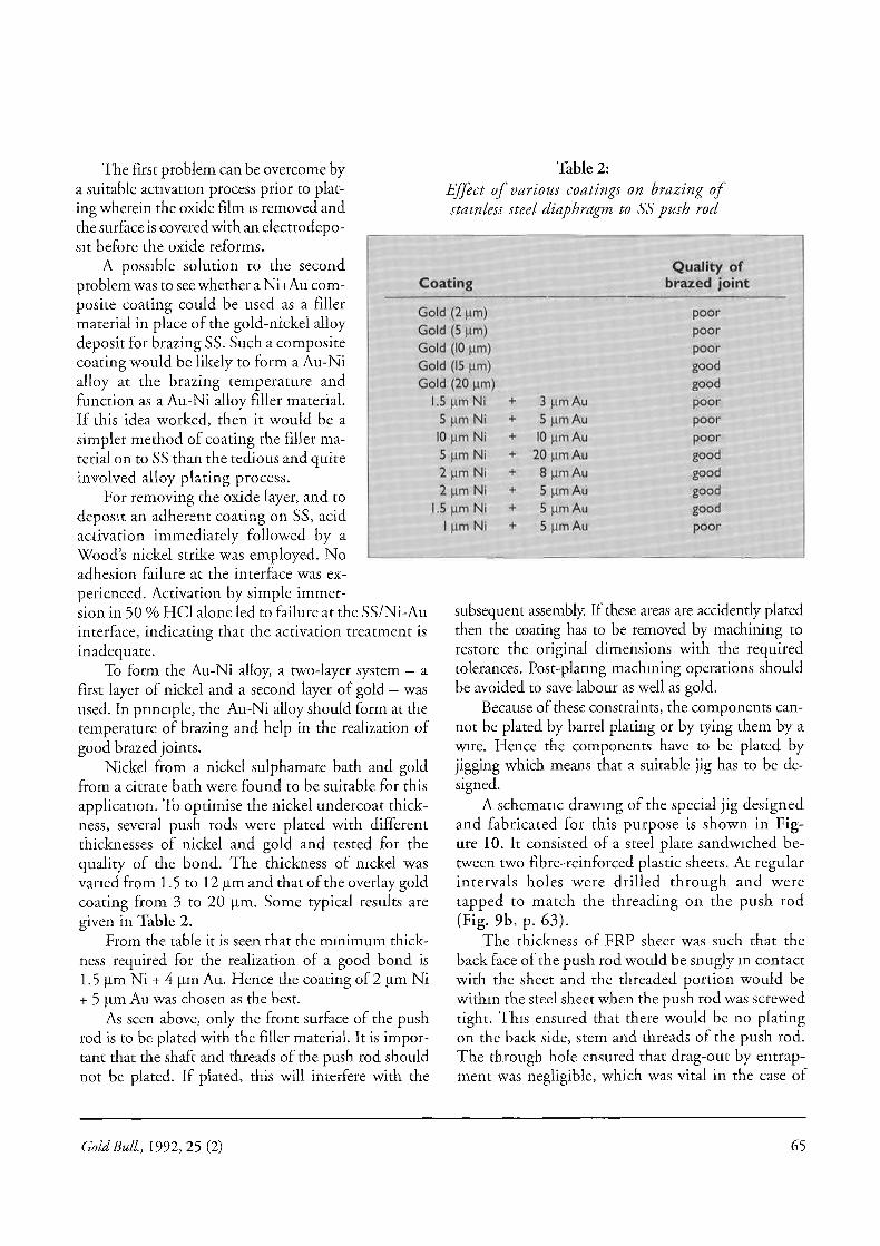
Figure 7:Typical R25 magnesium alloy component
(unlike that on Al) is porous and not of the self-heal-ing type and consequently it does not offer protection.However, it prevents the formation of metal-to-met-al bonding during plating, resulting in non-adherentdeposition.
As in the case of aluminium alloys, magnesiumalloys make the plating procedures still more com-plex. The alloying constituents, together with themagnesium matrix, form local cathodic and an-odic sites, introducing electrochemical heteroge-neity. If the cathodic site has low hydrogen over-voltage, hydrogen evolution is facilitated in theseareas and hence corrosion current is substantiallyincreased. The alloy composition, quality of thecastings, design of the castings, mechanical surfacepreparation and metal finishing processes determinethe quality of the coating concerned. The presence
Gold Bull., 1992, 25 (2) 61

Figure 8:Gold plated RZ 5 magnesium alloy box
left: patchy gold plating due . to improper pretreatmentright: uniform gold plating accomplished
by employing EN as a bond coat
of alloy impurity phases and different intermetallicphases differing in their chemical activity to differentreagents leads to patchy deposition. If the castingshave surface porosity, flaws or oxide and flux inclu-sions, the quality of the plating is seriously affected.In the design, if there are deep recesses, narrowcavities and sharp corners, uniformity of the coat-ing is very difficult to achieve. Since magnesiumis soft, the possibility of inclusion of SiC or Al203particles in the matrix during polishing and buff-ing and particles of heavy metals during shot blast-ing is another potential problem. Such inclusions,flaws, porosity and presence of different phasescause electrochemical heterogeneity. Plating onsuch alloy results in non-uniform depositionwhich results in vastly aggravated corrosion be-cause these defects tremendously accelerate gal-vanic corrosion.
All the above factors are to be looked into whiledeveloping a suitable process sequence for plating onmagnesium alloys.
Zincating followed by copper plating is the usualprocedure recommended for plating on magnesiumand its alloys. The zincating solution used for magne-sium differs from that used for alu-minium. It is an aqueous solution of azinc salt, pyrophosphate and a fluoridesalt with a small amount of carbonateadded to adjust the alkalinity in theproper range. Pyrophosphates assist theformation of an adherent zinc coating byreadily reacting with the surface films ofmagnesium oxide and hydroxide and dis-solve them by forming water solublecomplexes. The presence of fluoridehelps to control the rate of deposition.The bath is operated at 68 to 74 °C and,depending upon the alloy composition,bath temperature, and surface prepara-tion, treatment time varies from 2 to15 minutes.
However, on RZ5 magnesium al-loy, it was very difficult to get uniformzinc coating. The zinc coating waspatchyandnon-uniform. Doublezincat-ing, which is commonly used for most ofthe aluminium alloys, was found to beineffective in the case of magnesium al-
loys. The dissolution of the first layer of zinc in phos-phoric acid/ammonium fluoride followed by a secondimmersion in the zincating bath results in a largeamount ofgas evolution and consequent non-uniformcoverage ofthe magnesium alloy.
Direct electroless plating was tried after chemicaletching and it also resulted in non-uniform deposition.The problems encountered were:
— Excessive corrosion even under cathodic condi-tions, and
— exfoliation of the deposit.Detailed investigations showed that these difficultiesarose for the following reasons:- The grains in the substrate were coarse and non-
uniform.- The chemical composition of the alloy castings
showed variation from batch to batch and also fromlocation to location in one and the same casting.
- The rare earth addition instead of forming a mushycompound along the grain boundaries (as it isnormally supposed to) was seen to be distributedin a non-uniform fashion within the grains.Due to the variation in chemical composition, cata-
62 Gold Bull., 1992, 25 (2)

Figure 9a:Cross-sectional view (schematic) of a pressure transducer
employing a stainless steel diaphragm as a pressure sensor
GOLD PLATING.
Figure 9b:
Cross-sectional view (schematic) of the push rod showing the area overwhich gold plating is applied for brazing applications
/—S TR AIN GAUGE
YOKE ( BEAM )
PUSH ROD
OS DIAPHRAGM
PRESSURE PORT
lytic activities of different sites var-ied drastically leading to non-uni-form deposition Hence it wasthought that these problems couldbe overcome by adjusting the con-ditions of preplating such that thecompositional and metallurgicalheterogeneities do not significantlyinfluence the electrochemical prop-erties of the substrate during thepreplating operations.
The following process sequencewas found to be the best:- Acetone degrease, rinse.- Cleaning in alkali.
Mild chromic acid pickling (toremove the surface oxide, looselyadherent cold worked metal andsurface contamination).
- Fluoric acid dip:48 % HE 7.3 vol.%temp. = 25 - 30 °Ctime = 10 min.
- A.c. electrolytic treatment at5 V for two minutes. This stepis very important and ensuresthe uniformity in subsequentplating sequences. It makes thewhole surface uniformly activefor further electroless nickelplating, probably by forming anadsorbed film of fluoride afterdissolving away the surface oxideand hydroxide. Omitting thisstep results in patchy deposition(Fig. 8, left). On the other hand,it is possible to get very uniformgold deposition on magnesiumalloy boxes by means of thesefluoride dip and a.c. electrolysissteps (Fig. 8, right).
- Electroless nickel plating from afluoride-containing bath (Ta-ble 3b, p. 66). The pH of thebath is adjusted to be around 7.Electroless nickel is built up to5 um.
Gold Bull., 1992, 25 (2) 63

The stainless steel (SS) push rodbonded to the SS diaphragm (approx.0.1 mm thick) is a vital part of thetransducer. For the quantitative trans-mission of the load, the bond betweendiaphragm and push rod must be perfect.The joining of the push rod and thediaphragm is best carried out by vac-uum brazing. For this purpose, a thincoating of filler material has to be ap-plied to the front surface of the SS pushrod (Fig. 9b is a schematic drawing ofthe push rod).
Au-Ni alloy Au(82) -Ni(18) has beenwidely used for brazing stainless steel forspace applications [3]. Plating of Au-Nialloy on SS push rods poses the follow-ing problems:
Stainless steel also belongs to the class of difficult-to-plate materials because of the presence of a thintransparent oxide film of chromium/and or nickelwhich reforms quickly when destroyed. This filmprevents adhesion of the electrodeposit.Generally, alloy plating is a complex process andhence electroplating an alloy of specific composi-tion poses practical problems.
L
PUSH RO
F RPimonmes mazIeMbl
i MTN
VA/477 AINIMPIrtfirr420 'WA=aan. '`If& N M1WAsealattram r WI= PO AA
FRP
Nickel plating from standard nickel sulphamatebath (Table 3d, p. 66). The nickel coating is builtup to a thickness of 5 inn.Gold plating from neutral citrate bath (Table 3e,p. 66). A 5 um gold coating is applied.
Magnesium alloy boxes gold plated by the above pro-cedure were used in APPLE. APPLE successfully per-formed its mission for a period longer than the ex-pected life period of two years, therebydemonstrating the success of the goldplating.
GOLD PLATINGON STAINLESS STEELPUSH RODS
Figure 9a shows a schematic drawing ofa pressure transducer which makes use ofa diaphragm as a pressure sensor. The sens-ing diaphragm is bonded to a push rodwhich in turn is joined to a beam. Thepressure sensed by the diaphragm is thustransferred as a load to the beam. Theresulting strain in the beam, which isproportional to the pressure, is measuredby four strain gauges bonded onto it.
STEE
Figure 10:Cross-sectional view (schematic) of jig used for plating push rods
Figure 11:Typical gold plated push rod, with brazed
stainless steel diaphragm and assembled transducers
64 Gold Bug, 1992, 25 (2)
The first problem can be overcome bya suitable activation process prior to plat-ing wherein the oxide film is removed andthe surface is covered with an electrodepo-sit before the oxide reforms.
A possible solution to the secondproblem was to see whether a Ni+Au com-posite coating could be used as a fillermaterial in place of the gold-nickel alloydeposit for brazing SS. Such a compositecoating would be likely to form a Au-Nialloy at the brazing temperature andfunction as a Au-Ni alloy filler material.If this idea worked, then it would be asimpler method of coating the filler ma-terial on to SS than the tedious and quiteinvolved alloy plating process.
For removing the oxide layer, and todeposit an adherent coating on SS, acidactivation immediately followed by aWood's nickel strike was employed. Noadhesion failure at the interface was ex-perienced. Activation by simple immer-sion in 50 % HCI alone led to failure at the SS/Ni-Auinterface, indicating that the activation treatment isinadequate.
To form the Au-Ni alloy, a two-layer system — afirst layer of nickel and a second layer of gold — wasused. In principle, the Au-Ni alloy should form at thetemperature of brazing and help in the realization ofgood brazed joints.
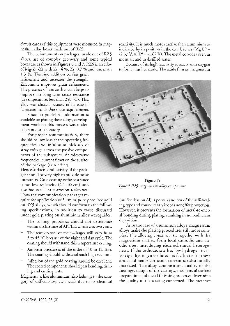
Nickel from a nickel sulphamate bath and goldfrom a citrate bath were found to be suitable for thisapplication. To optimise the nickel undercoat thick-ness, several push rods were plated with differentthicknesses of nickel and gold and tested for thequality of the bond. The thickness of nickel wasvaried from 1.5 to 12 nm and that of the overlay goldcoating from 3 to 20 Rm. Some typical results aregiven in Table 2.
From the table it is seen that the minimum thick-ness required for the realization of a good bond is1.5 pm Ni + 4 pm Au. Hence the coating of 2 pm Ni+ 5 pm Au was chosen as the best.
As seen above, only the front surface of the pushrod is to be plated with the filler material. It is impor-tant that the shaft and threads of the push rod shouldnot be plated. If plated, this will interfere with the
Table 2:Effect of various coatings on brazing ofstainless steel diaphragm to SS push rod
poor
poor
pockgoodgood
poor
poor
poor
goadgoodgoodgoodpoor
subsequent assembly. If these areas are accidently platedthen the coating has to be removed by machining torestore the original dimensions with the requiredtolerances. Post-plating machining operations shouldbe avoided to save labour as well as gold.
Because of these constraints, the components can-not be plated by barrel plating or by tying them by awire. Hence the components have to be plated byjigging which means that a suitable jig has to be de-signed.
A schematic drawing of the special jig designedand fabricated for this purpose is shown in Fig-ure 10. It consisted of a steel plate sandwiched be-tween two fibre-reinforced plastic sheets. At regularintervals holes were drilled through and weretapped to match the threading on the push rod(Fig. 9b, p. 63).
The thickness of FRP sheet was such that theback face of the push rod would be snugly in contactwith the sheet and the threaded portion would bewithin the steel sheet when the push rod was screwedtight. This ensured that there would be no platingon the back side, stem and threads of the push rod.The through hole ensured that drag-out by entrap-ment was negligible, which was vital in the case of
Gold (2 pm)Gold (5 pm)Gold (10 pm)Gold (15 pm)Gold (20 pm)
1.5 pm Ni
•
3 pro Au5 pm Ni
•
5 gm Au
10 gill Ni 4 10 pill Au5 p.m Ni
•
20 nrin ALI2 pm Ni
•
8 pm Au2 pm Ni
•
5 p.m Au
1.5 pm Ni 5 pm Au
I pm Ni 5 pen Au
Quality ofCoating
brazed joint
Gold Bull., 1992, 25 (2) 65

Nickel su I pharnate
Nickel chloride
Boric acid
Current density
Time
150 el
5 VIg:/1
2.5 mAlctn
5 rinintites.
e) Gold plating bath
Potassium gold cyanide
Ammonium citrate
Temperature
Current density
pH
Anodes
Time
gil
- 30 dC
ririA/cr626
Platinised titanium'
38 minkes
a) Alkaline cleaning solution
NaOH
Na3PO4
Current density
Time
b) Electroless nickel bath
• ..10
10. %,„
100 hiNcrn.:22. mibuts
Basic nickel carbonate
HF (70%)
Citric add
Ammonium bifluoride
Sodium hypophosphite
NH4OH (30 %)
PhTemperature
c) Wood's nickel strike bath
NiC12 • 6H20
HCI
Current density
Time
d) Sulphamate nickel bath
109 mI/I
5 git10 WI
20 g/1
10 M1/1
4.5 - 7
30-35 °C
100 g/1
180 mill
20 inA/cMI
30 secondS
gold plating in view of its high cost. The finalprocedure followed for plating the pushrods for brazing is given below.
Degrease the push rods and fix in the jig.- Degrease again with methyl alcohol to
remove any grease introduced while han-dling.
- Cathodically clean in the standard alka-line solution (Table 3a)
- Rinse thoroughly in distilled water.- Immerse in 50 % HC1 for 10 seconds
and rinse thoroughly.— Give nickel strike from Wood's nickel
bath (Table 3c).- Plate nickel from the sulphamate bath
(Table 3d).- Rinse thoroughly and plate gold from the
citrate gold bath (Table 3e).- Drain to minimise drag-out loss, rinse in
a rinse tank, wash in running water, rinsein distilled water and dry.
Push rods plated by this procedure bondedvery well to the diaphragm. Figure 11 showsrespectively the gold plated push rod afterbrazing to the SS diaphragm and the assem-bled transducers.
This process has been used by the pres-sure transducer fabrication facility for severalyears. More than 600 transducers have beenproduced by them and they found that theprocess gave good bonds and virtually zerorejection rate. In addition this process usedonly 5 wn of gold as compared to 25 tm ofgold recommended by the French process[4]. The jig effectively prevented the deposi-tion of gold on unwanted areas and therebysaved not only gold but also the extra ma-chining needed to machine away the un-wanted gold.
Table 3:Summary of plating procedures for stainless steel
References
1. L. Holt and J. Stayer, Trans. Inst. Met.Fin., 3. M.M. Schwartz, Gold Bull., 1975, 8, 1021972, 50, 23
4. French process (Personal communication)2. G.B. Munier, Plating, 1969, 56 , 1151
66 Gold Bull., 1992, 25 (2)