Embed Size (px)
Citation preview

GmbH
LITEF DOCUMENT NO. 141450-0000-840
ATTITUDE AND HEADING REFERENCE SYSTEM
(AHRS)
LCR-92 PART NO. 141450-XXXXLCR-92 PART NO. 141852-XXXXLCR-92 PART NO. 124210-XXXXLCR-92 PART NO. 142300-3200
INSTALLATION / MAINTENANCE INSTRUCTION
JUNE 1995REVISION 4, NOVEMBER 1998


GmbH
LITEF DOCUMENT No: 141450–0000–840November 1998
ATTITUDE AND HEADING REFERENCE SYSTEM
LCR-92 PART NO. 141450-XXXX
LCR-92 PART NO. 141852-XXXX
LCR-92 PART NO. 124210-XXXX
LCR-92 PART NO. 142300-3200
INSTALLATION / MAINTENANCE INSTRUCTION
June 1995Revision 4, November 1998
LITEF GmbH
Loerracher Str. 18, D–79115 Freiburg Tel.: (0761) 49010
� 06.1995 LITEF GmbHAll rights reserved, including the right to copy, distribute and translate. No part of this document may be reproduced without the express prior written consent of LITEF, not even for archive purposes and may e.g. not be made use of, reproduced or disseminated by use of electronic means.


GmbHINSTALLATION / MAINTENANCE INSTRUCTION
HIGHLIGHTS Page 1/2
To : HOLDERS OF INSTALLATION / MAINTENANCE INSTRUCTION ( LCR-92 ) PART NO. 141450-0000-840
REVISION 4, DATED NOVEMBER 1998
The changes incorporated with this revision are :
(1).................. Complete re-working of the technical content (all text pages and illustrations) and the re-structuring of the layout of the IMI,
with the main points highlighted as follows :
(2).................. Incorporating both FX-125 and FX-220 MSUs into one figure (previously twofigures).
(3).................. Modifications to figure 4 to give a clear interpretation to the technician (when installingthe MSU).
(4).................. Addition of a CalPROM drawing.
(5).................. Modifications to figure 15 to give a clear interpretation to the technician (when installingand working on the cable and / or cable connector).
(6).................. System wiring tables simplified to facilitate ease of reading.
(7).................. Alterations to figures 13 and 14.
(8).................. Addition of Section 5.
(9).................. Addition of Appendix 1.
(10)................ PNs removed from INSTALLATION / MAINTENANCE INSTRUCTION title at thetop of each page,
and
(11)................ many minor alterations too numerous to be listed here.
November 1998


GmbHINSTALLATION / MAINTENANCE INSTRUCTION
INTRODUCTION Page 1/2
November 1998
INTRODUCTION
The LCR-92 is an Attitude and Heading Reference System (AHRS). It combines the functions of avertical gyro, a gyro stabilized magnetic compass and 3 rate gyros within one single unit. TheLCR-92 is a strapdown system, in which the sensors - fiber optic gyros (FOG) and level sensors -are literally “STRAPPED” to the aircraft structure. The AHRS provides attitude and heading data,as well as information about the dynamics of the aircraft to the cockpit displays, the flight controlsystem and other users in the aircraft. The principal data provided by the LCR-92 AHRS is :
- pitch angle- roll angle- magnetic heading- angular rates around the aircraft axes
The LCR-92 system consists of the following components :
- AHRU (Attitude and Heading Reference Unit)- MSU CalPROM- Flux-Valve- CCU (Compass Controller Unit, optional)
AHRU
The AHRU is the main AHRS component, containing the sensors (FOG and level sensors), proces-sor, power supply, and interfaces to the users.
MSU CalPROM
The MSU CalPROM is an external detachable device, located at the AHRU front panel. It stores theaircraft specific information necessary to compensate the flux-valve errors and the misalignment ofthe mounting tray.
Flux-Valve
The flux-valve provides the AHRU with information about the earth’s magnetic field. In an aircraftit is usually fitted in an area selected to minimize interference by ferromagnetic materials and mag-netic fields generated by the aircraft.
CCU
The compass control functions can be integrated into the cockpit design or, as an option, be installedas a separate Compass Control Unit. The LITEF Compass Control Unit is an optional componentwhich allows the AHRU to be decoupled from the flux-valve and to set the system to any desiredheading. The system then operates in the DG mode with a heading performance equivalent to a freedirectional gyro.


GmbHINSTALLATION / MAINTENANCE INSTRUCTION
PREFACE Page1/2
November 1998
THE LCR-92 INSTALLATION / MAINTENANCE MANUAL IS COMPILED OF FIVE MAIN SECTIONS, NAMELY :
SECTION 1
SECTION 2
SECTION 3
SECTION 4
installation instructions
description and operation
testing and troubleshooting
removal and installation
For a more comprehensive listing refer to the table of contents
AND WITH EACH SECTION BEING DIVIDED INTO PARAGRAPHS AND SUB-PARAGRAPHS
SECTION 5 storage / packaging / transportation
PREFACE
APPENDIX 1RTCA/DO-160C environmental qualification form
AND AN APPENDIX :


GmbHINSTALLATION / MAINTENANCE INSTRUCTION
REVISIONS Page 1/2
November 1998
RECORD OF REVISIONS
REVNO.
ISSUEDATE
DATEINSERTED
BY REVNO.
ISSUEDATE
DATEINSERTED
BY
1234
July 1996October 1996
Nov. 1996Nov. 1998
incorporatedincorporatedincorporatedincorporated

GmbHINSTALLATION / MAINTENANCE INSTRUCTION
TEMPORARY REVISIONS Page 1/2
November 1998
RECORD OF TEMPORARY REVISIONS
TEMPORARYREV NO.
PAGE NO. ISSUE DATE BY DATEREMOVED
BY

GmbHINSTALLATION / MAINTENANCE INSTRUCTION
SERVICE BULLETIN LIST Page 1/2
November 1998
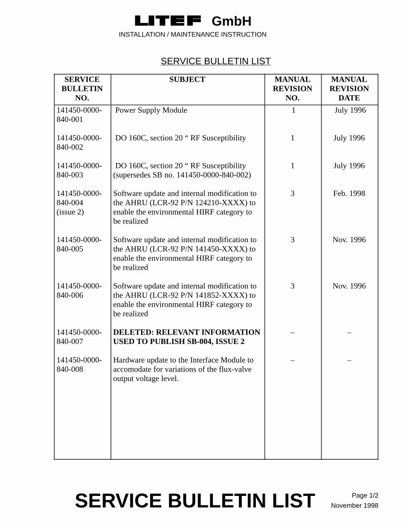
SERVICE BULLETIN LIST
SERVICEBULLETIN
NO.
SUBJECT MANUALREVISION
NO.
MANUALREVISION
DATE
141450-0000-840-001
141450-0000-840-002
141450-0000-840-003
141450-0000-840-004(issue 2)
141450-0000-840-005
141450-0000-840-006
141450-0000-840-007
141450-0000-840-008
Power Supply Module
DO 160C, section 20 “ RF Susceptibility
DO 160C, section 20 “ RF Susceptibility (supersedes SB no. 141450-0000-840-002)
Software update and internal modification tothe AHRU (LCR-92 P/N 124210-XXXX) toenable the environmental HIRF category tobe realized
Software update and internal modification tothe AHRU (LCR-92 P/N 141450-XXXX) toenable the environmental HIRF category tobe realized
Software update and internal modification tothe AHRU (LCR-92 P/N 141852-XXXX) toenable the environmental HIRF category tobe realized
DELETED: RELEVANT INFORMATIONUSED TO PUBLISH SB-004, ISSUE 2
Hardware update to the Interface Module toaccomodate for variations of the flux-valveoutput voltage level.
1
1
1
3
3
3
–
–
July 1996
July 1996
July 1996
Feb. 1998
Nov. 1996
Nov. 1996
–
–


GmbHINSTALLATION / MAINTENANCE INSTRUCTION
EFFECTIVE PAGES Page 1/2
November 1998
LIST OF EFFECTIVE PAGES
SECTION PAGE DATE
Title PageIntroductionPrefaceRecord of RevisionsRecord of Temporary RevisionsService Bulletin ListList of Effective PagesList of IllustrationsList of TablesTable of ContentsAbbreviationsFrontispieceTitle Page, Section 1Installation InstructionsTitle Page, Section 2Description and OperationTitle Page, Section 3Testing and TroubleshootingTitle Page, Section 4Removal/InstallationTitle Page, Section 5Storage / Packaging / TransportationAppendix 1RTCA/DO-160C EnvironmentalQualification Form
1/21/21/21/21/21/21/21/21 through 41/21/2
1 through 52
1 through 8
1 through 10
1 through 2
1 through 6
1 through 2
November 1998November 1998November 1998November 1998November 1998November 1998November 1998November 1998November 1998November 1998November 1998November 1998November 1998November 1998November 1998November 1998November 1998November 1998November 1998November 1998November 1998November 1998November 1998November 1998

GmbHINSTALLATION / MAINTENANCE INSTRUCTION
TABLES Page 1/2
November 1998
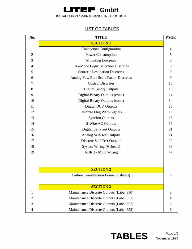
LIST OF TABLES
No. TITLE PAGE
SECTION 1
1 Connectors Configuration 4
2 Power Consumption 5
3 Mounting Discretes 8
4 DG-Mode Logic Selection Discretes 8
5 Source / Destination Discretes 9
6 Analog Yaw Rate Scale Factor Discretes 9
7 Control Discretes 10
8 Digital Binary Outputs 13
9 Digital Binary Outputs (cont.) 14
10 Digital Binary Outputs (cont.) 14
11 Digital BCD Outputs 15
12 Discrete Flag Warn Signals 16
13 Synchro Outputs 18
14 2-Wire AC Outputs 19
15 Digital Self-Test Outputs 21
16 Analog Self-Test Outputs 21
17 Discrete Self-Test Outputs 22
18 System Wiring (9 sheets) 39
19 AHRU / MSU Wiring 47
SECTION 2
1 Failure Transmission Frame (2 sheets) 6
SECTION 3
1 Maintenance Discrete Outputs (Label 350) 3
2 Maintenance Discrete Outputs (Label 351) 4
3 Maintenance Discrete Outputs (Label 352) 5
4 Maintenance Discrete Outputs (Label 353) 6


GmbHINSTALLATION / MAINTENANCE INSTRUCTION
ILLUSTRATIONS Page 1/2
November 1998
LIST OF ILLUSTRATIONS
No. TITLE PAGE
introduction LCR-92 Attitude and Heading Reference System Frontispiece
SECTION 1
1 Interface Diagram LCR-92 7
2 Examples of a typical wiring of a discrete output, e.g. AHRU Warn 17
3 AHRU Outline 28
4 KMT 112 MSU Outline and Mounting Diagram 29
5 FX-120 MSU Outline and Mounting Diagram 30
6 FX-125 / FX-220 MSU Outline and Mounting Diagram 31
7 CCU Outline and Mounting Diagram 32
8 Tray Outline - Without Fan (P/N 124260) 33
9 Tray Outline - With Fan (P/N 140691) 34
10 Tray Outline - Without Fan (P/N 124260-5000) 35
11 Tray Outline - With Fan (P/N 140691-5000) 36
12 CalPROM Outline 37
13 Interconnection Diagram CCU, LCR-92 48
14 Interconnection Diagram Ground Discrete Reference 49
15 Shield termination of connectors using Metal Backshell / Strain Relief method 50
16 Bonding Strap for the installation of AHRU P/N 141852-3211 51
SECTION 3
1 Typical LCR-92 AHRS Installation 2
SECTION 5
1 Packaging of Electrostatic Discharge Sensitive Devices 3
2 Electrostatic Discharge Sensitive Device Labels (typical examples) 4
3 Location of Identification Markings 5


GmbHINSTALLATION / MAINTENANCE INSTRUCTION
CONTENTS Page 1
November 1998
TABLE OF CONTENTS
PARAGRAPH PAGE
SECTION 1 INSTALLATION INSTRUCTIONS
1 INSTALLATION DATA 1
Dimensions and Weight 4
Location 4
Connectors 4
Power 5
2 WIRING 5
3 SIGNAL INPUT 6
Program Pins 6
Parity 8
Azimuth Mounting Discretes 8
DG-Mode Logic Selection 8
Source Destination Identifier 9
Analog Yaw Rate Scale Factor Selection 9
Turn Rate Select 9
Control Discretes 10
MSU Calibration Control Switch 10
Digital Inputs 10
ARINC 429 Inputs 10
RS-422 Input 11
Analog Inputs 11
4 SIGNAL OUTPUT 12
Digital Outputs 12
ARINC 429 Outputs 12
RS-422 Output 15
Discrete Flag Warn Signals 16
Analog Outputs 18
Synchro Outputs 18
2-Wire AC Outputs 19
2-Wire DC Outputs 19

GmbHINSTALLATION / MAINTENANCE INSTRUCTION
CONTENTS Page 2
November 1998
PARAGRAPH PAGE
Self-Test Outputs 21
5 COOLING REQUIREMENTS 23
6 AHRU ALIGNMENT REQUIREMENTS 23
Installation Tray 23
7 FLUX VALVE (MSU) CALIBRATION 23
General 23
Index Error 24
Calibration Procedure 24
MSU Calibration Procedure/Checklist 26
8 OUTLINE DRAWINGS 27
AHRU 28
MSU, Bendix/King 29
MSU, Honeywell (FX-120) 30
MSU, Honeywell (FX-125 / FX-220) 31
Compass Control Unit 32
Tray, without Fan (P/N 124260) 33
Tray, with Fan (P/N 140691) 34
Tray, without Fan (P/N 124260-5000) 35
Tray, with Fan (P/N 140691-5000) 36
CalPROM 37
9 SYSTEM WIRING 38
J1 (Power Supply) 39
J2 (Fan Supply) 39
J3 (Synchro) (only AHRU / P/N 124210-2011) 40
J3 (Synchro) (only AHRU / P/N 141XXX-2XXX) 41
J3 (Synchro) (only AHRU / P/N 141852-32XX) 42
J3 (Synchro) (only AHRU / P/N 141XXX-30XX and 141XXX-31XX)
43
J4 (I/O) (only AHRU / P/N 124210-XXXX) 44
J4 (I/O) (only AHRU / P/N 141450-XXXX and 141852-XXXX)
45
J5 (CalPROM) 47

GmbHINSTALLATION / MAINTENANCE INSTRUCTION
CONTENTS Page 3November 1998
PARAGRAPH PAGE
SECTION 2 DESCRIPTION AND OPERATION
1 GENERAL 1
2 PURPOSE OF EQUIPMENT 1
3 LEADING PARTICULARS 1
4 DESCRIPTION 1
Location of Units in Aircraft 1
Outline and Mounting Drawings 1
AHRU 1
MSU 2
CCU (optional) 2
5 MODES OF OPERATION 2
Alignment 3
General 3
Alignment Phase 1 3
Alignment Phase 2 3
Normal Mode 4
Slaved Mode 4
DG-Mode 4
MSU Calibration Mode 4
Maintenance Mode 4
General 4
Failure Logging and Malfunction Storage 5
Output of the Failure History and Elapsed Time 5
6 POWER INTERRUPTIONS 8
General 8
Short Power Interrupt 8
Long Power Interrupt 8
SECTION 3 TESTING AND TROUBLESHOOTING
1 GENERAL 1
2 MAINTENANCE DISCRETE OUTPUTS 3

GmbHINSTALLATION / MAINTENANCE INSTRUCTION
CONTENTS Page 4
November 1998
PARAGRAPH PAGE
3 INITIAL INSTALLATION OF AN AHRU FAULT FINDINGCHECK-LIST
7
AHRS EQUIPPED WITHOUT A SYNCHRO CARD 7
Step 1 : EFIS does not display any data 7
Step 2 : Heading and Attitude Flags Displayed (invalid data) 7
Step 3 : Heading Flag Displayed (invalid data) 7
Step 4 : Attitude Flag Displayed (invalid data) 8
Step 5 : Heading Check 8
Step 6 : Attitude Check 8
Step 7 : CCU Check 8
Step 8 : Self-Test 8
Step 9 : Cal-Mode Switch 9
Step 10 : On Ground / In Air Switch 9
AHRS EQUIPPED WITH A SYNCHRO CARD 9
4 LITEF LCR-92 LEVEL 1 TEST SET 10
SECTION 4 REMOVAL / INSTALLATION
1 GENERAL 1
2 REMOVAL OF AHRU 1
3 INSTALLATION OF AHRU 1
SECTION 5 STORAGE / PACKAGING / TRANSPORTATION
1 GENERAL 1
2 STORAGE 1
3 PACKAGING 1
Special Packaging Requirements 2
4 TRANSPORTATION 2
APPENDIX 1 RTCA/DO-160C ENVIRONMENTALQUALIFICATION FORM

GmbHINSTALLATION / MAINTENANCE INSTRUCTION
ABBREVIATIONS Page 1/2
November 1998
LIST OF ABBREVIATIONS
The following are a list of abbreviations that are used in the text:
AC Alternating currentA/C AircraftAF Audio FrequencyAHRS Attitude and Heading Reference SystemAHRU Attitude and Heading Reference UnitARINC AERONAUTICAL RADIO, INCORPORATEDATT AttitudeBIT Built-In TestCalPROM Calibration PROMCCU Compass Control UnitDC Direct CurrentDG Directional GyroDITS Digital Information Transfer SystemEEPROM Electrically Erasable Programmable Read Only MemoryFOG Fibre Optic GyroGND GroundHDG HeadingHIL Hardware-In-the-Loop (test method)I/F InterfaceMSU Magnetic Sensor UnitMTBF Mean Time Between FailuresN/A Not ApplicableNCD No Computed Data (ARINC 429)RAM Random Access MemoryP/N Part NumberPROM Programmable Read Only Memory RF Radio FrequencyRTCA Radio Technical Commission for AERONAUTICSS/N Serial Number SAV Standard Applied VoltageSDI Source Destination Identifier (ARINC 429)SSM Sign Status Matrix (ARINC 429)TR Turn RateTSO Technical Standard OrderUUT Unit Under TestYR Yaw Rate

GmbHINSTALLATION / MAINTENANCE INSTRUCTION
FRONTISPIECE Page 1/2November 1998
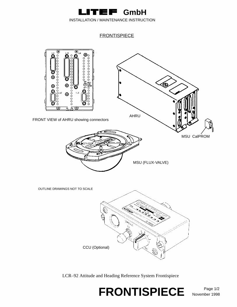
LCR–92 Attitude and Heading Reference System Frontispiece
CCU (Optional)
MSU CalPROM
AHRU
MSU (FLUX-VALVE)
FRONT VIEW of AHRU showing connectors
OUTLINE DRAWINGS NOT TO SCALE
FRONTISPIECE


GmbHINSTALLATION / MAINTENANCE INSTRUCTION
LITEF DOCUMENT No: 141450–0000–840TITLE PAGE SECTION 1
November 1998
SECTION 1
INSTALLATION INSTRUCTIONS


GmbHINSTALLATION / MAINTENANCE INSTRUCTION
LITEF DOCUMENT No: 141450–0000–840SECTION 1 Page 1
November 1998
1 Installation Data
This section contains information that will aid in the installation of the Attitude and Heading ReferenceSystem (AHRS, frontispiece). The dash number formats of the various versions of LCR-92 are as shownbelow, and the ancillary equipment applicable to the various systems is laid out in the configuration onpage 3.
P/N 124210-XXXX Standard Performance AHRUP/N 141450-XXXX High Performance AHRUP/N 141852-XXXX Standard Performance AHRUP/N 142300-XXXX Standard Performance AHRU
0 Basic Software Version1 Software Upgrade 12 Software Upgrade 2 (except for P/N
124210-XXXX)
0 Basic Hardware Version1 Improved Hardware for DO-160C Sec. 20 Cat. W2 Improved Hardware for DO-160C Sec. 20 Cat. Y
(except for P/N 124210-XXXX)
0 Bendix/King Flux-Valve Interface 1 Honeywell Flux-Valve Interface2 Honeywell Flux-Valve Interface and 167 mV/deg
two wire AC Output for Version -32XX only
1 Digital Interface only2 Digital and Synchro Interface with 12 bit
A/D attitude resolution3 Digital and Synchro Interface with 16 bit
A/D attitude resolution (except for P/N 124210-XXXX)
LCR-92 (P/N124210) CONFIGURATION
Unit Part No. (Bendix/King Flux Valve Interface)
Attitude Heading and Reference P/N 124210-1011 Digital InterfaceUnit P/N 124210-2011 Digital & Synchro Interface (12
bit D/A attitude resolution)

GmbHINSTALLATION / MAINTENANCE INSTRUCTION
LITEF DOCUMENT No: 141450–0000–840SECTION 1 Page 2
November1998
LCR-92 (P/N141450) CONFIGURATION
Unit Part No. (Bendix/King Flux Valve Interface)
Attitude Heading and Reference P/N 141450-1000/1011/1022 Digital InterfaceUnit P/N 141450-2000/2011/2022 Digital & Synchro Interface (12
bit D/A attitude resolution)
P/N 141450-3000/3011/3022 Digital & Synchro Interface (16 bit D/A attitude resolution)
Part No. (Honeywell Flux Valve Interface)
P/N 141450-1100/1111/1122 Digital Interface
P/N 141450-2100/2111/2122 Digital & Synchro Interface (12 bit D/A attitude resolution)
P/N 141450-3100/3111/3122 Digital & Synchro Interface (16 bit D/A attitude resolution)
LCR-92 (P/N141852) CONFIGURATION
Unit Part No. (Bendix/King Flux Valve Interface)
Attitude Heading and Reference P/N 141852-1000/1011/1022 Digital InterfaceUnit P/N 141852-2000/2011/2022 Digital & Synchro Interface (12
bit D/A attitude resolution)
P/N 141852-3000/3011/3022 Digital & Synchro Interface (16 bit D/A attitude resolution)
Part No. (Honeywell Flux Valve Interface)
P/N 141852-1100/1111/1122 Digital Interface
P/N 141852-2100/2111/2122 Digital & Synchro Interface (12 bit D/A attitude resolution)
P/N 141852-3100/3111/3122 Digital & Synchro Interface (16 bit D/A attitude resolution)
P/N 141852-3200/3211/3222 Digital & Synchro Interface (16 P/N 142300-3200 bit D/A attitude resolution), and
167 mV / deg two wire AC Output
NOTE : P/N 142300-3200 AHRU is identical to P/N 141852-3200 with the exception of the nameplate and the deletion of TSO C4c.

GmbHINSTALLATION / MAINTENANCE INSTRUCTION
LITEF DOCUMENT No: 141450–0000–840 SECTION 1 Page 3
November 1998
CONFIGURATION FOR EQUIPMENT THAT IS APPLICABLE EITHER TO THE :-
LCR-92 (P/N124210) CONFIGURATION or LCR-92 (P/N141450) CONFIGURATION orLCR-92 (P/N141852) CONFIGURATION
Magnetic Sensor Units (MSU)(Flux-valve)
P/N 1071-1052-00* Bendix/King KMT 112
P/N 620359** Honeywell FX-120
P/N 656520** Honeywell FX-125 / 656520
P/N 2594484** Honeywell FX-220 / 2594484
MSU Calibration PROM P/N 124282-0000
Installation Kit(Mating Connector Set)
P/N 124284-0000 (AHRU with Synchro Interface) plasticP/N 124284-1100 (AHRU with Synchro Interface and
Bonding Strap) metalP/N 124284-2100 (AHRU with Synchro Interface) metal
P/N 124285-0000 (AHRU without Synchro Interface) plasticP/N 124285-2100 (AHRU without Synchro Interface) metal
AHRU Mounting Tray P/N 124260-0000 (excluding Fan)
P/N 124260-5000 (excluding Fan)
P/N 140691-0000 (including Fan)
P/N 140691-5000 (including Fan)
Compass Controller Unit P/N 140855-0010 (5V Lighting, black panel)(CCU, optional) P/N 140855-0020 (28V Lighting, black panel)
P/N 140855-0030 (5V Lighting, grey panel)
P/N 140855-0040 (28V Lighting, grey panel)
Installation Kit for CCU(if fitted)
P/N 141468-0000
NOTE * to be ordered directly from Bendix-King** to be ordered directly from HoneywellSystems with P/N 141450-3111 and P/N 141852-3111 shall be installed with tray P/N 124260-5000 or P/N 140691-5000 ONLY.

GmbHINSTALLATION / MAINTENANCE INSTRUCTION
LITEF DOCUMENT No: 141450–0000–840SECTION 1 Page 4
November1998
1.1 Dimensions and Weight
Dimensions Configuration Weight
AHRU, see Fig. 3 with synchro interface less than 2.5 kg (5.5lbs)
without synchrointerface
less than 2.1 kg (4.6lbs)
MSU, see Figs. 4 to 6 incl. Bendix/KingHoneywellHoneywellHoneywell
KMT112 ; 136 gms (0.3lbs) FX-120 ; 680 gms (1.5lbs)FX-125 ; 680 gms (1.5lbs)FX-220 ; 680 gms (1.5lbs)
CCU, see Fig. 7 0.4 kg (0.8lbs) max
Mounting Tray, see Figs. 8 to 11 with cooling fan approx. 0.5 kg (1.1lbs)
MSU CalPROM, see Fig. 12
without cooling fan approx. 0.3 kg (0.6lbs)
less than 35 gms (0.08lbs)
1.2 Location
The AHRU is generally located in the aircraft’s equipment bay electronics rack, and its major axes mustbe parallel or perpendicular to the major axes of the aircraft. The CCU is installed on a panel in thecockpit. The MSU should be located as far as possible from all sources of local magnetic disturbancessuch as engines, electrical cables or radio equipment. A wing tip or tail section location will usually besatisfactory.
1.3 Connectors
The AHRU external connectors are Sub-Min-D type with metric M3 screw lock and having thefollowing pin configurations :
Connector Function Pins/Sockets Connector type Mating connector
J1 Power 15 HDC15M HDC15F
J2 Fan Supply 9 HDC09F(not required)* HDC09M(not required)*
J3 Synchro Output 44 DD44M DD44F
J4 Input/Output 62 DD62M DD62F
J5 MSU CalPROM 15 DD15F(not required)* DD15M(not required)*
Table 1 Connectors Configuration

GmbHINSTALLATION / MAINTENANCE INSTRUCTION
LITEF DOCUMENT No: 141450–0000–840 SECTION 1 Page 5
November 1998
* No wiring is required for connector J2 (Fan Supply), and for connector J5 (CalPROM),because themating connectors are integral parts of the Mounting Tray with Fan and the CalPROM itself. If a Fan isnot used a plastic cap should be installed on connector J2. The metal block attached to the end of theCalPROM retaining cable should be permanently affixed to the Mounting Tray with the two machinescrews provided.
The mating connectors with metric (M3) screw lock shall have metal or metallized plastic backshells.
The mating connector for the KMT 112 flux valve is Allied Signal P/N 030 2190 00
The CCU mating connector is made up of connector M83723/75R-1415N with M85049/52-1-14Nbackshell.
1.4 Power
The AHRU is designed to operate from either one of two independent 28 VDC input power supplies.The power consumption of the AHRU is listed below. The maximum power consumption of the optionalcooling fan is less than 3 Watts (which is not included in table 1 below). Maximum nominal current is 2.5amperes (at 13 volts). At power on, surge currents can be as high as 10A for 10ms.
Configuration Power Consumption
nom. max.
without Synchro Interface 20 W 25 W
with Synchro Interface (max. load) 35 W 40 W
with Synchro Interface (high impedance load) 25 W 30 W
Table 2 Power Consumption
2 Wiring
Wiring details are provided in Table 18 at the end of this section.

GmbHINSTALLATION / MAINTENANCE INSTRUCTION
LITEF DOCUMENT No: 141450–0000–840SECTION 1 Page 6
November1998
3 Signal Input
In case of installation of dual systems do not connect the switched input discretes such as OnGround / In Air, Maintenance, and Self Test in parallel. It is recommended that these inputs be keptisolated by the use of relay contacts or optocouplers.
3.1 Program Pins
There are ten AHRU connector pins allocated for external program control as follows:
Pin Function
J4-32 Program Pin Common
J4-14 Mount Position No. 1
J4-35 Mount Position No. 2
J4-34 SDI 1
J4-54 SDI 2
J4-12 DG-Mode Logic Select
J4-53 Yaw Rate Scale Factor Select No. 1
J4-11 Yaw Rate Scale Factor Select No. 2
J4-17 Turn Rate Select
J4-13 Parity (odd)
Program Pin Common is grounded inside the AHRU. External jumpers from the other program pins toProgram Pin Common or to 28 VDC for Turn Rate Select respectively, allow the AHRU to beprogrammed to get various installations and customized functions as described on pages 8 and 9.(Program Pin Common should not be grounded to aircraft system ground).
An overview of signal inputs / outputs is shown in Figure 1.

GmbHINSTALLATION / MAINTENANCE INSTRUCTION
LITEF DOCUMENT No: 141450–0000–840 SECTION 1 Page 7
November 1998
Figure 1 Interface Diagram LCR–92
(**) not present in systems with P/N -XX11/-XX22
FAN
FOR LAB TESTS ONLY
+/– 15Vdc Aux. Power (**)

GmbHINSTALLATION / MAINTENANCE INSTRUCTION
LITEF DOCUMENT No: 141450–0000–840SECTION 1 Page 8
November1998
3.1.1 Parity
Parity check of Discrete Input Program Pins:
Mounting Position 1 + Mounting Position 2
+ DG-Mode Logic Select
+ Yaw Rate Select 1 + Yaw Rate Select 2 = odd
+ Turn Rate Select
+ Parity Pin
If the number of selected ( i.e. grounded or set to 28 VDC respectively ) pins is even, then the parity pinJ4-13 has to be grounded, in order to get an odd parity.
3.1.2 Azimuth Mounting Discretes
Azimuth mounting orientation in the A/C is identified by Mounting Position No.1 and No.2 Pins.
Program Pins Plug Fwd. Plug Aft. Plug Rt. Wg. Plug Lt. Wg.
Mount Pos. 1 (J4-14) open jump to common open jump to common
Mount Pos. 2 (J4-35) open open jump to common jump to common
Table 3 Mounting Discretes
3.1.3 DG–Mode Logic Selection
The DG-Mode Logic Selection discrete is applied to the program pin (J4-12). This results in theDG/MAG Mode shown under the derived input control discrete.
Program Pin J4-12DG–Mode Logic Select
DG/MAG Mode J4-57Input = 28 VDC
DG/MAG Mode J4-57Input = open
open DG-Mode Slaved Mode
jump to common Slaved Mode DG-Mode
Table 4 DG-Mode Logic Selection Discretes

GmbHINSTALLATION / MAINTENANCE INSTRUCTION
LITEF DOCUMENT No: 141450–0000–840 SECTION 1 Page 9
November 1998
3.1.4 Source Destination Identifier
Program Pins n/a System No. 1 System No. 2 System No. 3
SDI 1(J4-34)
open jump to common open jump to common
SDI 2(J4-54)
open open jump to common jump to common
Table 5 Source/Destination Discretes
3.1.5 Analog Yaw Rate Scale Factor Selection
NOTEApplicable only for AHRS equipped with a synchro card.
Program Pins 200 mV/�/s 100 mV/�/s 333 mV/�/s 666 mV/�/s
YR-Scale 1(J4-53)
open open jump to common jump to common
YR-Scale 2(J4-11)
open jump to common open jump to common
Table 6 Analog Yaw Rate Scale Factor Discretes
3.1.6 Turn Rate Select
Output of Turn Rate at ARINC label 330 instead of Yaw Rate is selected by J4-17 (referenced to J4-36*).
For calculation and bandwidth of the Turn Rate output refer to paragraph 7.3 (page 24).
Program Pin J4-17 ARINC Label 330
open Yaw Rate
+ 28 VDC Turn Rate
* see figure 14 (page 49).

GmbHINSTALLATION / MAINTENANCE INSTRUCTION
LITEF DOCUMENT No: 141450–0000–840SECTION 1 Page 10
November1998
3.2 Control Discretes
There are 15 AHRU connector pins allocated for control discretes as follows:
In case of multiple installations each control discrete shall be wired and controlled independently.
J4-38 MSU Calibration Discrete +28 V = MSU Calibration Enable**
J4-55 Selftest data enable GND = Test data enable (TTL logic)
J4-33 Maintenance data enable GND = Maintenance data enable (TTL logic)
J4-57 DG mode select see Table 4
J4-16 Slew Left*) +28 V = Slew Left Platform Hdg
J4-58 Slew Right*) +28 V = Slew Right Platform Hdg
J4–37 On ground/in air Logic( weight on wheels )
GND = in airOpen = on ground (28 VDC logic)
J4-36 Ground Discrete Ref. Reference for SAV input discretesConnect to J1-15 ( see figures 13 and 14, pages48/49)
Table 7 Control Discretes
*) Slew function is enabled after alignment is finished.
In DG-Mode initial slew rate is 2 �/s , after 3 secs, 8 �/s.
In Slave Mode platform heading will be set to MSU heading input.
** valid for P/N 141XXX-XX22
3.3 MSU Calibration Control Switch/Discrete
The MSU calibration control switch, located on the front of the AHRU, sets the system into the MSUCalibration Mode. For P/N 141XXX-XX22 a SAV Control Discrete (J4-38) also sets the system into theMSU Calibration Mode.
3.4 Digital Inputs
3.4.1 ARINC 429 Inputs
The system provides two independent ARINC 429 low speed (12.5kHz) input interfaces. The currentsystem mechanisation requires no ARINC 429 input. However, these interfaces are implemented forgrowth potential reasons.

GmbHINSTALLATION / MAINTENANCE INSTRUCTION
LITEF DOCUMENT No: 141450–0000–840 SECTION 1 Page 11
November 1998
3.4.2 RS-422 Input
The system provides two independent RS-422 input interfaces. Interface 1 is used for test and calibrationpurposes. Interface 2 is a spare input.
Hardware provisions are made to operate these interfaces as RS-485 bus interfaces.
Transmission Rate: 9600 Baud
Data: 8 Data Bits
Control: 1 Start Bit
1 Parity Bit (odd)
2 Stop Bits
NOTE : The interface may be operated using the LITEF LCR-92 Level 1 Test Set 309444.
3.5 Analog Inputs
Magnetic Heading Input
The AHRU requires a magnetic heading input direct from a flux valve.
MSU Reference Input/Output
The input MSU REF. IN (J4-60) has to be connected to MSU REF. OUT (J4-39) inside connector J4.For P/N 124210-XXXX J4-59 has to be connected to J4-18 as well.
AC Synchro Reference Input
The AHRU requires the following 26 VRMS, 400 Hz reference signals :
PNs XXXXXX-20XX, -21XX Attitude Reference
Heading 1 Reference
PNs XXXXXX-30XX, -31XX, and
-32XX
Attitude Reference
Heading 1 and 2 References
These signals are to be the same phase as the reference used by the connected analog indicator or controlcomputer.

GmbHINSTALLATION / MAINTENANCE INSTRUCTION
LITEF DOCUMENT No: 141450–0000–840SECTION 1 Page 12
November1998
4 Signal Output
The AHRU provides following power for system use :
+24 VDC cooling fan power
+28 VDC CCU power / discrete inputs
10.8 - 40 VRMS, 400 Hz flux valve excitation
4.1 Digital Outputs
4.1.1 ARINC 429 Outputs
The system provides three identical two-wire digital data output busses per ARINC 429, all of whichinclude the binary and BCD data described as follows:
GmbHINSTALLATION / MAINTENANCE INSTRUCTION
LITEF DOCUMENT No: 141450–0000–840 SECTION 1 Page 13
November 1998
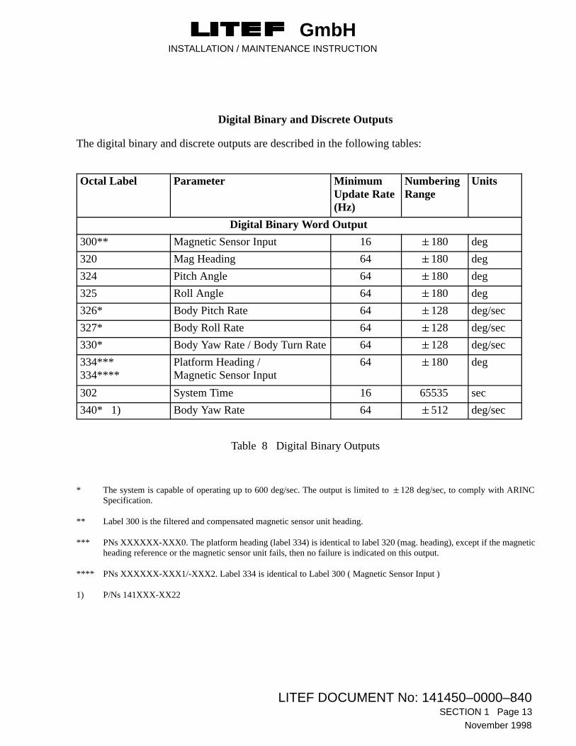
Digital Binary and Discrete Outputs
The digital binary and discrete outputs are described in the following tables:
Octal Label Parameter MinimumUpdate Rate(Hz)
NumberingRange
Units
Digital Binary Word Output
300** Magnetic Sensor Input 16 �180 deg
320 Mag Heading 64 �180 deg
324 Pitch Angle 64 �180 deg
325 Roll Angle 64 �180 deg
326* Body Pitch Rate 64 �128 deg/sec
327* Body Roll Rate 64 �128 deg/sec
330* Body Yaw Rate / Body Turn Rate 64 �128 deg/sec
334***334****
Platform Heading / Magnetic Sensor Input
64 �180 deg
302 System Time 16 65535 sec
340* 1) Body Yaw Rate 64 �512 deg/sec
Table 8 Digital Binary Outputs
* The system is capable of operating up to 600 deg/sec. The output is limited to �128 deg/sec, to comply with ARINCSpecification.
** Label 300 is the filtered and compensated magnetic sensor unit heading.
*** PNs XXXXXX-XXX0. The platform heading (label 334) is identical to label 320 (mag. heading), except if the magneticheading reference or the magnetic sensor unit fails, then no failure is indicated on this output.
**** PNs XXXXXX-XXX1/-XXX2. Label 334 is identical to Label 300 ( Magnetic Sensor Input )
1) P/Ns 141XXX-XX22
GmbHINSTALLATION / MAINTENANCE INSTRUCTION
LITEF DOCUMENT No: 141450–0000–840SECTION 1 Page 14
November1998
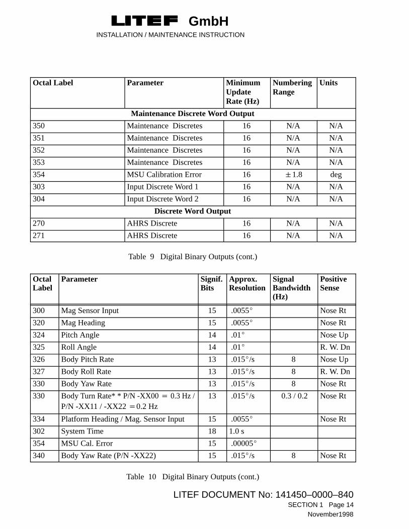
Octal Label Parameter MinimumUpdateRate (Hz)
NumberingRange
Units
Maintenance Discrete Word Output
350 Maintenance Discretes 16 N/A N/A
351 Maintenance Discretes 16 N/A N/A
352 Maintenance Discretes 16 N/A N/A
353 Maintenance Discretes 16 N/A N/A
354 MSU Calibration Error 16 �1.8 deg
303 Input Discrete Word 1 16 N/A N/A
304 Input Discrete Word 2 16 N/A N/A
Discrete Word Output
270 AHRS Discrete 16 N/A N/A
271 AHRS Discrete 16 N/A N/A
Table 9 Digital Binary Outputs (cont.)
OctalLabel
Parameter Signif.Bits
Approx.Resolution
SignalBandwidth(Hz)
PositiveSense
300 Mag Sensor Input 15 .0055� Nose Rt
320 Mag Heading 15 .0055� Nose Rt
324 Pitch Angle 14 .01� Nose Up
325 Roll Angle 14 .01� R. W. Dn
326 Body Pitch Rate 13 .015�/s 8 Nose Up
327 Body Roll Rate 13 .015�/s 8 R. W. Dn
330 Body Yaw Rate 13 .015�/s 8 Nose Rt
330 Body Turn Rate* * P/N -XX00 � 0.3 Hz /P/N -XX11 / -XX22 �0.2 Hz
13 .015�/s 0.3 / 0.2 Nose Rt
334 Platform Heading / Mag. Sensor Input 15 .0055� Nose Rt
302 System Time 18 1.0 s
354 MSU Cal. Error 15 .00005�
340 Body Yaw Rate (P/N -XX22) 15 .015�/s 8 Nose Rt
Table 10 Digital Binary Outputs (cont.)

GmbHINSTALLATION / MAINTENANCE INSTRUCTION
LITEF DOCUMENT No: 141450–0000–840 SECTION 1 Page 15
November 1998
Digital BCD Outputs
The table below shows the digital BCD outputs of the AHRU.
Label (Octal) Function Min. Update Rate (Hz)
046 Software Version 1
377 Equipment Identification 1
Table 11 Digital BCD Outputs
4.1.2 RS-422 Output
The system provides two independent RS-422 output interfaces. Interface 1 is used for maintenance dataoutput and test and calibration purposes. Interface 2 is a spare output.
Hardware provisions are made to operate these interfaces as RS-485 bus interfaces.
Transmission Rate: 9600 Baud
Data: 8 Data Bits
Control: 1 Start Bit
1 Parity Bit (odd)
2 Stop Bits
NOTE : The interface may be operated using the LITEF LCR-92 Level 1 Test Set 309444.
NOTES : applicable to Table 12 :
*For PNs, XXXXXX-2XXX and -3XXX only.
** The autopilot heading interlock contact is open when:–heading is invalid–the system is switched from DG to slave mode, open for two seconds.-slew right or left is selected, open for at least two seconds.–MSU Calibration Mode is selected.
*** For PNs, 141450-XXXX and 141852-XXXX only.**** For PNs, 124210-XXXX only
GmbHINSTALLATION / MAINTENANCE INSTRUCTION
LITEF DOCUMENT No: 141450–0000–840SECTION 1 Page 16
November1998
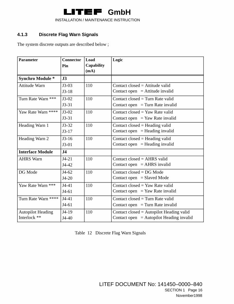
4.1.3 Discrete Flag Warn Signals
The system discrete outputs are described below ;
Parameter ConnectorPin
LoadCapability(mA)
Logic
Synchro Module * J3
Attitude Warn J3-03J3-18
110 Contact closed = Attitude validContact open = Attitude invalid
Turn Rate Warn *** J3-02J3-31
110 Contact closed = Turn Rate validContact open = Turn Rate invalid
Yaw Rate Warn **** J3-02J3-31
110 Contact closed = Yaw Rate validContact open = Yaw Rate invalid
Heading Warn 1 J3-32J3-17
110 Contact closed = Heading validContact open = Heading invalid
Heading Warn 2 J3-16J3-01
110 Contact closed = Heading validContact open = Heading invalid
Interface Module J4
AHRS Warn J4-21J4-42
110 Contact closed = AHRS validContact open = AHRS invalid
DG Mode J4-62J4-20
110 Contact closed = DG ModeContact open = Slaved Mode
Yaw Rate Warn *** J4-41J4-61
110 Contact closed = Yaw Rate validContact open = Yaw Rate invalid
Turn Rate Warn **** J4-41J4-61
110 Contact closed = Turn Rate validContact open = Turn Rate invalid
Autopilot HeadingInterlock **
J4-19J4-40
110 Contact closed = Autopilot Heading validContact open = Autopilot Heading invalid
Table 12 Discrete Flag Warn Signals

GmbHINSTALLATION / MAINTENANCE INSTRUCTION
LITEF DOCUMENT No: 141450–0000–840 SECTION 1 Page 17
November 1998
Figure 2 Examples of a typical wiring of a discrete output, e.g. AHRS Warn
GmbHINSTALLATION / MAINTENANCE INSTRUCTION
LITEF DOCUMENT No: 141450–0000–840SECTION 1 Page 18
November1998
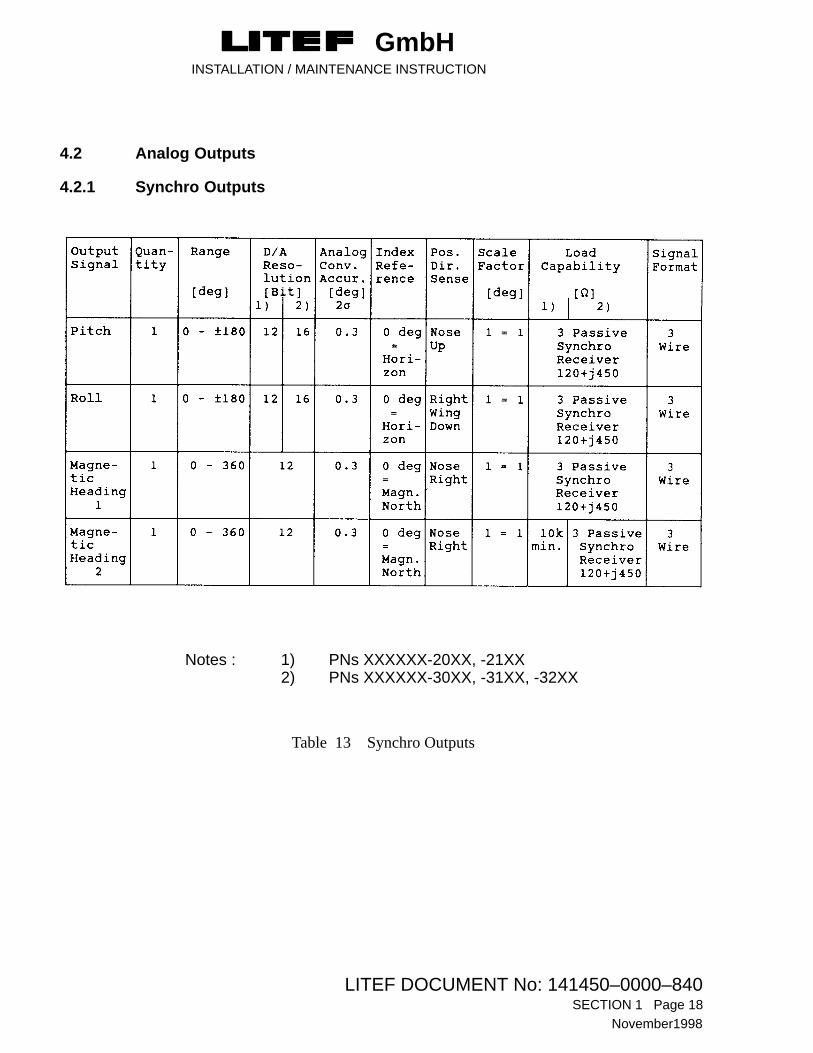
4.2 Analog Outputs
4.2.1 Synchro Outputs
Notes : 1) PNs XXXXXX-20XX, -21XX2) PNs XXXXXX-30XX, -31XX, -32XX
Table 13 Synchro Outputs

GmbHINSTALLATION / MAINTENANCE INSTRUCTION
LITEF DOCUMENT No: 141450–0000–840 SECTION 1 Page 19
November 1998
4.2.2 2–Wire AC Outputs
Notes : 1) PNs XXXXXX-20XX, -21XX2) PNs XXXXXX-30XX, -31XX, 3) PNs XXXXXX-32XX** Positive sense in phase with reference
Table 14 2-Wire AC Outputs
4.2.3 2-Wire DC Outputs
Mag Heading Slaving Error
Defined as Platform Heading - Magnetic Sensor Input
Format 2-wire DC current �200 �A
Scaling �200 �A, �15 deg (full scale) into 1 kohm load

GmbHINSTALLATION / MAINTENANCE INSTRUCTION
LITEF DOCUMENT No: 141450–0000–840SECTION 1 Page 20
November1998
Yaw Rate Output
PNs XXXXXX-2XXX, -3XXX
Format 2-wire DC �4 V full scale
Scale Factors 100, 200, 333 or 666 mV/deg/sec depending on program pin wiring, see Table 6
or : single DC Output, referenced to Turn Rate RTN / Yaw Rate RTN and
1/2 Scalefactor ( PNs XXXXXX-3XXX only ).
Bandwidth output is filtered with an 8 Hz low pass filter.
Sense Output voltage shall be positive for CW rate as viewed from above.
Range 0 – �40, �20, �12 or �6 deg/sec.
Scale Factor Accuracy�10 %
Offset 50mV
Load 1 k�
Turn Rate Output
PNs XXXXXX-2XXX, -3XXX
Format 2-Wire DC �4 V full scale
Scale Factor 333mV/deg/sec
or : single DC Output, referenced to Turn Rate RTN / Yaw Rate RTN and
1/2 Scalefactor ( PNs XXXXXX-3XXX only ).
Turn rate is calculated from yaw rate and roll angle:
Turn rate = yaw rate / cos ( roll angle �60° )
Bandwidth Output is filtered with a low pass filter.
PNs XXXXXX-XXX0 : time constant 0.6s.
PNs XXXXXX-XXX1/-XX22 : time constant 0.9s.
Range 0 – �12 deg/sec
Scale Factor Accuracy�10%
Offset 50mV
Load 1 K�

GmbHINSTALLATION / MAINTENANCE INSTRUCTION
LITEF DOCUMENT No: 141450–0000–840 SECTION 1 Page 21
November 1998
4.3 Self-Test Outputs
Functional selftest can be activated when aircraft is on ground and the selftest data discrete is grounded.These values are latched for 1 second* after the ground from J4-55 is removed. The values are listed inthe tables which follow.
* 1 minute ONLY applicable to units with the PN 124210-XX00.
Output Signal Octal Label Self-test Values
Discrete Words 270/271 N/A
Magnetic Sensor Input 300 N/A
Mag Heading 320 15 deg
Pitch Angle 324 + 5 deg (Nose Up)
Roll Angle 325 + 45 deg (Right Wing Down)
Pitch Rate Body 326 10 deg/sec (Nose Up)
Roll Rate Body 327 10 deg/sec (Right Wing Down)
Yaw Rate Body 330/340* 10 deg/sec (Nose Right)
Platform Heading / Mag. Sensor Input 334 22.5 deg
* P/N -XX22
Table 15 Digital Self-Test Outputs
Synchro Outputs
Output Signal Self–test Value
Heading 1Heading 2
15 deg Nose Right15 deg Nose Right
PitchRoll
+ 5 deg Nose Up+45 deg Right Wing Down
DC Voltage Outputs
Slaving ErrorYaw RateTurn Rate
+15 deg Nose Right +6 deg/sec Nose Right +3 deg/sec Nose Right
Table 16 Analog Self-Test Outputs

GmbHINSTALLATION / MAINTENANCE INSTRUCTION
LITEF DOCUMENT No: 141450–0000–840SECTION 1 Page 22
November1998
ATT WARN � Attitude invalid
HDG WARN 1 � Heading 1 invalid
HDG WARN 2 � Heading 2 invalid
AHRS WARN � AHRS valid
YAW RATE WARN � Yaw Rate invalid
TURN RATE WARN � Turn Rate invalid
DG MODE � DG Mode selected
AUTOPILOT HDG INTERLOCK � AUTOPILOT HDG invalid
Table 17 Discrete Self-Test Output

GmbHINSTALLATION / MAINTENANCE INSTRUCTION
LITEF DOCUMENT No: 141450–0000–840 SECTION 1 Page 23
November 1998
5 Cooling Requirements
In order to improve the system reliability, the AHRU installation tray optionally incorporates an integralcooling fan. Increased reliability will result from operation with the optional cooling fan.
6 AHRU Alignment Requirements
6.1 Installation Tray
The outline drawings of the installation trays with and without fan are shown in Figures 9, 10, 11 and 12.
The orthogonal alignment of the installation tray with respect to the pitch, roll and azimuth axis of theaircraft is fundamental for the operation of the AHRS. Therefore, the AHRU Installation Tray, forhard-mount as well as palletized installation, must be aligned to within �0.2 degrees to the aircraft axes.
In order to increase the alignment accuracy, the measured actual installation alignment errors can bestored in the MSU calibration PROM. The AHRU uses the stored coefficients for misalignmentcorrection during operation.
NOTE : The alignment errors can be stored using the LITEF LCR-92 Level 1 Test Set309444.
7 Flux Valve (MSU) Calibration
7.1 General
An automatic flux valve calibration procedure is implemented in the AHRU software. The proceduredoes not require supporting equipment. The procedure must be performed in a position without localdisturbances of the earth’s magnetic field as no compensation for such disturbances can be made. Toensure that all of the factors requiring compensation are present the procedure must be performed withthe engine(s) running and all electrical systems used in flight switched on. Particular attention should bepaid to systems in the neighbourhood of the flux valve, strobe and/or position lights, pitot tube heatingetc. Prior to an initial Flux-valve installation a survey should be carried out to determine the magnetismparameters of the location. If readings are greater than the acceptable limits the affected parts must bedegaussed, until all readings are within the limits laid down. One possible approach is to use a needlecompass and check that the magnetism readings are within the acceptable limits. When the procedurehas been completed, both single and dual cycle magnetic disturbances produced by the aircraft and itssystems are practically eliminated. A reference direction is not required. Any initial aircraft heading canbe used. If the Air/Ground discrete indicates that the aircraft is on the ground the flux valve calibrationmode may be engaged. If the Air/Ground discrete indicates that the aircraft is in the air the MSUCAL MODE switch position is ignored and the normal mode of operation remains selected.
Note If Electrical systems, which can only be switched on in the air, must remain off, the headingsystem may exhibit uncompensated errors during flight. A way should be found to switch themon without changing the ’On Ground’ indication to AHRU.

GmbHINSTALLATION / MAINTENANCE INSTRUCTION
LITEF DOCUMENT No: 141450–0000–840SECTION 1 Page 24
November1998
7.2 Index Error
When a new flux valve is installed perform a four point cardinal swing in order to eliminate the indexerror.The index error of the MSU is not compensated by the automatic MSU calibration. Prior to theprocedure the MSU has to be pre-aligned manually with an accuracy of �1 degree. After the MSUcalibration the MSU may be realigned manually to eliminate the residual index error.
During the procedure the aircraft is turned clockwise to eight (initial heading, plus seven positions)different headings about 45� apart; a �5� error in spacing is acceptable. These headings are indicated onthe appropriate system’s primary heading indicator.
The aircraft can be rotated about it’s vertical axis or taxied in a circle to align with the required headings.
The operator supervises the procedure via the aircraft instruments (HSI, RMI). The displayed headingand the heading flag are used to reach the 7 headings used and to determine when the next headingchange is to be made. See the detailed procedure which follows this general description.
7.3 Calibration Procedure
The calibration mode is selected by the MSU CAL MODE switch on the front panel of the LCR-92AHRU being placed in the up (ON) position.
As long as a heading change is less than 5� in the calibration mode initial position the displayed headingis the raw flux valve heading input.
When the heading change exceeds 5� away from the position heading, the heading relative to the initialprocedure heading (0 degrees) is displayed. This means that headings do not have to be calculated by theground crew, the next required heading is always the next multiple of 45� � 5° ( e.g. 45°, 90°, 135°,180° etc.).
In each of the eight positions, including the initial position, the system accepts heading from the fluxvalve. The time required for data collection depends on aircraft movements, caused for example by windor propeller rotation. During data collection and the turns between positions the Heading Warn Flag isdisplayed. At the end of each data collection period the flag disappears, generally in less than 20 seconds,to indicate that the turn to the next heading can be started.
If the flag does not disappear, it indicates that either the heading is outside the �5� tolerance, or data hasnot been correctly collected because of excessive aircraft motion. When this happens the procedure mustbe rerun.
The Attitude Warn flag is displayed throughout the performance of the procedure.
GmbHINSTALLATION / MAINTENANCE INSTRUCTION
LITEF DOCUMENT No: 141450–0000–840 SECTION 1 Page 25
November 1998
After data has been collected for each of the eight headings (0 to 315 degrees indication on the compasscard irrespective of the initial heading), the system calculates the compensation factors and stores thisdata in the MSU calibration PROM. The MSU calibration PROM is attached to the AHRU mountingtray. AHRU replacement does not require a new flux valve calibration.
The heading display after the compensation factors have been calculated, immediately switches to anindication of the quality of the compensation available. The value indicated is the standard deviation ofthe residual error multiplied by 100. A sucessful calibration is indicated by the retraction of the HDGWARN flag.
If the heading warn flag continues to be displayed, the procedure failed. The indicated results are notstored in the MSU calibration PROM and the last valid values are retained. If the heading is greater than100� (residual error 1�) the calibration should be regarded as invalid, even if the heading warn flag isretracted. In this case the procedure must be re–run.
After a successful calibration, the system is returned to the normal mode of operation by placing theAHRU switch MSU CAL MODE down to the OFF position. All warning flags disappear and normaloperation is resumed.
If the MSU CAL MODE is accidentally left in the ON position, the attitude warn flag will continue to bedisplayed during ground operation. The display of these flags should prevent flight with the switch inthis position. However if the aircraft takes off despite the warning, normal operation will be resumedwhen the Ground/Air discrete input indicates ’in air’. On the ground, incorrect headings will bedisplayed.

GmbHINSTALLATION / MAINTENANCE INSTRUCTION
LITEF DOCUMENT No: 141450–0000–840SECTION 1 Page 26
November1998
7.4 MSU Calibration Procedure/Checklist
A/C in location with no external magnetic disturbances
engine(s) running
all electrical equipment switched on
AHRS switched on
alignment completed, all flags out of view
MSU CAL MODE switch switched to ”ON” (up)
ATT Flag in view
HDG Flag in view
Initial HDG indication: ____
HDG Flag disappears
A/C to 45� indic. HDG
HDG Flag in view
HDG Flag disappears
A/C to 90� indic. HDG
HDG Flag in view
HDG Flag disappears
A/C to 135� indic. HDG
HDG Flag in view
HDG Flag disappears
A/C to 180� indic. HDG
HDG Flag in view
HDG Flag disappears
A/C to 225� indic. HDG
HDG Flag in view
HDG Flag disappears
A/C to 270� indic. HDG
HDG FLag in view
HDG Flag disappears
A/C to 315� indic. HDG
HDG Flag in view
HDG Flag disappears
Indication of calibration qualityHDG indication on compass: _____
MSU CAL MODE switch to ”OFF” (down)
HDG Flag out of view
ATT Flag out of view

GmbHINSTALLATION / MAINTENANCE INSTRUCTION
LITEF DOCUMENT No: 141450–0000–840 SECTION 1 Page 27
November 1998
8 Outline Drawings
The outline drawing of the AHRU is shown in Fig. 3. Outline drawings of the various MSUs producedby Bendix/King and Honeywell are shown in Figs. 4 to 6 inclusive. Likewise, the outline drawing for theCCU is shown in Fig. 7. Figs. 8, 9, 10 and 11 show the mounting trays with or without fans fitted. Lastly, the CalPROM is illustrated in Fig. 12.
The outline drawings are shown on the following pages (28 to 37 inclusive).

GmbHINSTALLATION / MAINTENANCE INSTRUCTION
LITEF DOCUMENT No: 141450–0000–840SECTION 1 Page 28
November1998
8.1 AHRU
Figure 3 AHRU Outline
GmbHINSTALLATION / MAINTENANCE INSTRUCTION
LITEF DOCUMENT No: 141450–0000–840 SECTION 1 Page 29
November 1998
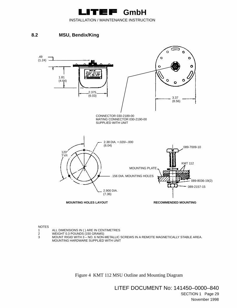
8.2 MSU, Bendix/King
Figure 4 KMT 112 MSU Outline and Mounting Diagram
CONNECTOR 030-2189-00MATING CONNECTOR 030-2190-00SUPPLIED WITH UNIT
MOUNTING HOLES LAYOUT
2.900 DIA.(7.36)
2.38 DIA. +.020/–.000(6.04)
MOUNTING PLATE
3.37(8.56)
1.81(4.64)
.49(1.24)
2.375(6.03)
120°TYP.
KMT 112
089-7009-10
089-8036-19(2)
089-2157-15
RECOMMENDED MOUNTING
NOTES1 ALL DIMENSIONS IN ( ) ARE IN CENTIMETRES2 WEIGHT 0.3 POUNDS (150 GRAMS)3 MOUNT RIGID WITH 3 – NO. 6 NON-METALLIC SCREWS IN A REMOTE MAGNETICALLY STABLE AREA.
MOUNTING HARDWARE SUPPLIED WITH UNIT
.156 DIA. MOUNTING HOLES

GmbHINSTALLATION / MAINTENANCE INSTRUCTION
LITEF DOCUMENT No: 141450–0000–840SECTION 1 Page 30
November1998
8.3 MSU, Honeywell
Figure 5 FX-120 MSU Outline and Mounting Diagram

GmbHINSTALLATION / MAINTENANCE INSTRUCTION
LITEF DOCUMENT No: 141450–0000–840 SECTION 1 Page 31
November 1998
8.4 MSU, Honeywell
Figure 6 FX-125 / FX-220 MSU Outline and Mounting Diagram

GmbHINSTALLATION / MAINTENANCE INSTRUCTION
LITEF DOCUMENT No: 141450–0000–840SECTION 1 Page 32
November1998
8.5 Compass Control Unit
Figure 7 CCU Outline and Mounting Diagram
MATING CONNECTOR M83723-75R1415NGEGENSTECKER M83723-75R1415N

GmbHINSTALLATION / MAINTENANCE INSTRUCTION
LITEF DOCUMENT No: 141450–0000–840 SECTION 1 Page 33
November 1998
8.6 Tray, without Fan
Figure 8 Tray Outline - Without Fan (P/N 124260)
GmbHINSTALLATION / MAINTENANCE INSTRUCTION
LITEF DOCUMENT No: 141450–0000–840SECTION 1 Page 34
November1998
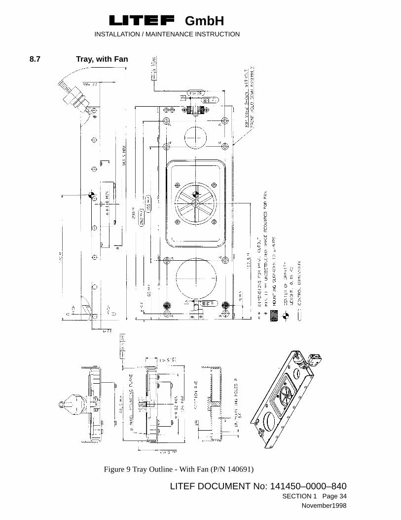
8.7 Tray, with Fan
Figure 9 Tray Outline - With Fan (P/N 140691)

GmbHINSTALLATION / MAINTENANCE INSTRUCTION
LITEF DOCUMENT No: 141450–0000–840 SECTION 1 Page 35
November 1998
8.8 Tray without Fan
Figure 10 Tray Outline - Without Fan (P/N 124260-5000)
GmbHINSTALLATION / MAINTENANCE INSTRUCTION
LITEF DOCUMENT No: 141450–0000–840SECTION 1 Page 36
November1998
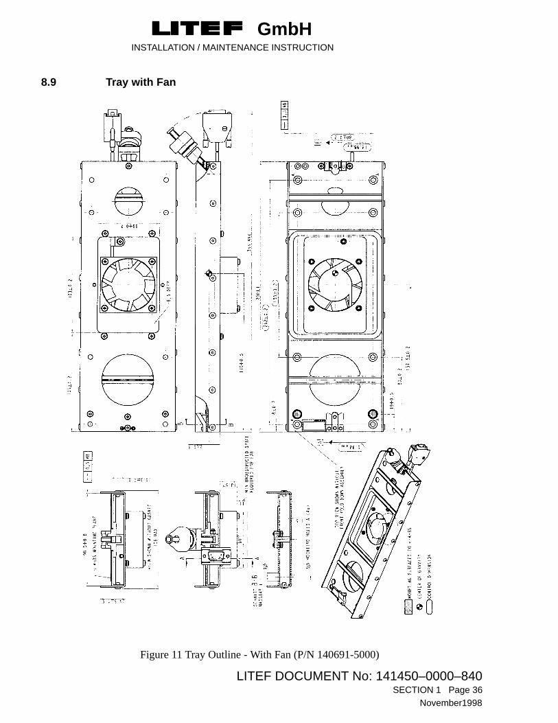
8.9 Tray with Fan
Figure 11 Tray Outline - With Fan (P/N 140691-5000)

GmbHINSTALLATION / MAINTENANCE INSTRUCTION
LITEF DOCUMENT No: 141450–0000–840 SECTION 1 Page 37
November 1998
8.10 CalPROM
Figure 12 CalPROM Outline
CalPROM Module
Lettering i.a.w. MIL-STD-130 or equivalent letteringDescription. PN. SN. REV ESD-label
Connector end housing
Nylon strap
On delivery connector will be fitted with a dustcap
Dimensions in millimetres

GmbHINSTALLATION / MAINTENANCE INSTRUCTION
LITEF DOCUMENT No: 141450–0000–840SECTION 1 Page 38
November1998
9 System Wiring
The following notes apply, where indicated.
NOTESTwisted and Shielded Wires - Wires should be shielded or twisted and shielded as indicated with an insulating jacket over the shield: The shield should be carried through each break and should be connected at both ends external to the equipment using metal backshell / strain relief of the respective connector, (refer to Figure 15). The Pigtail method shall be avoided.
External Program Control - Refer to Paragraph 3 for usage of external program control pins.
MSU Shield Grounding - The shielded multiple conductor cable carrying the sensitive signalsfrom the MSU should have its shield grounded at the backshell of the respective connector.
Figures 13 and 14 illustrate the interconnection between the CCU and LCR-92, and the interconnectionof the ground discrete reference respectively.
Figure 16 shows the Bonding Strap for the installation of AHRU with the P/N 141852-3211.
NOTEThe system wiring is laid out with particular reference to the various part numbers for the LCR-92, i.e., J1, J2 and J5 are the same for all systems, whereas
J3 and J4 are laid out in full under the designated part number concerned.
This is for ease of use by the technician concerned.

GmbHINSTALLATION / MAINTENANCE INSTRUCTION
LITEF DOCUMENT No: 141450–0000–840 SECTION 1 Page 39
November 1998
9.1 J1 (Power Supply)
Electrical Pin Assignment J1 (Power Supply)
FUNCTION CONNECTOR PIN IN/OUT AWG SIGNAL FORMAT LOAD
+28 VDC PRIM A/C POWER J1-01 ––––––––––––––––––– I (22)* AIRCRAFT 28 VDC 2 A MAX+28 VDC PRIM A/C POWER J1-09 ––––––––––––––––––– I (22)* AIRCRAFT 28 VDC 2 A MAX28 VDC PRIM RETURN J1-02 ––––––––––––––––––– I (22)* DC POWER GROUND 2 A MAX28 VDC PRIM RETURN J1-10 ––––––––––––––––––– I (22)* DC POWER GROUND 2 A MAX
+28 VDC AUX A/C Power J1-03 ––––––––––––––––––– I (22)* AIRCRAFT 28 VDC 2 A MAX+28 VDC AUX A/C Power J1-11 ––––––––––––––––––– I (22)* AIRCRAFT 28 VDC 2 A MAX28 VDC AUX RETURN J1-04 ––––––––––––––––––– I (22)* DC POWER GROUND 2 A MAX28 VDC AUX RETURN J1-12 ––––––––––––––––––– I (22)* DC POWER GROUND 2 A MAX
+24 VDC SYSTEM J1-13 ––––––––––––––––––– O (24) FOR LAB TEST ONLY24 VDC SYST. RETURN J1-05 ––––––––––––––––––– O (24) FOR LAB TEST ONLY
+28 VDC CCU/DISCRETES J1-08 ––––––––––––––––––– O (24) +28 VDC FOR CCU/INPUT DISCRETES28 VDC RTN J1-15 ––––––––––––––––––– O (24) 28VDC RETURN
SPARES J1-06, J1-07, J1-14
* For P/N -1XXX AWG 24 may be used
9.2 J2 (Fan Supply)
Note : This connector is permanently attached to the fan wiring, therefore no installation wiring is required.
Electrical Pin Assignment J2 (Fan Supply)
FUNCTION CONNECTOR PIN IN/OUT AWG SIGNAL FORMAT LOAD
+24 VDC FAN POWER J2-03 ––––––––––––––––––– O (24) 100 mA MAX24 VDC RETURN J2-02 ––––––––––––––––––– O (24) 100 mA MAX
FAN TEST ENABLE A J2-04 ––––––––––––––––––– I (24) JUMPER INSIDE THEFAN TEST ENABLE B J2-05 ––––––––––––––––––– I (24) FAN CONNECTER
SPARES J2-01, J2-06 to J2-09
Table 18 System Wiring (Sheet 1 of 9)

GmbHINSTALLATION / MAINTENANCE INSTRUCTION
LITEF DOCUMENT No: 141450–0000–840SECTION 1 Page 40
November1998
9.3 J3 (Synchro) (only AHRU / PN 124210-2011)
Electrical Pin Assignment J3 (Synchro)
FUNCTION CONNECTOR PIN IN/OUT AWG SIGNAL FORMAT LOAD
ATTITUDE HI J3-04 –––––�––––♦ –––––––– I (24) 26 VRMS AC 400 Hz 10 mA RMS MAX.REFERENCE LO J3-19 –––––�––––♦ –––––––– I (24) FLOATING INPUT
X(S1) J3-11 –––––�––––♦ –––––––– O (24) 3-WIRE SYNCHRO OUTPUTPITCH SYNCHRO Z(S2) J3-26 –––––�––––♦ –––––––– O (24) 11.8 VRMS LEG TO LEG 3 x (120 + j450)�
Y(S3) J3-40 –––––�––––♦ –––––––– O (24) 400 Hz (USES ATT. REF)
X(S1) J3-10 –––––�––––♦ –––––––– O (24) 3-WIRE SYNCHRO OUTPUTROLL SYNCHRO Z(S2) J3-25 –––––�––––♦ –––––––– O (24) 11.8 VRMS LEG TO LEG 3 x (120 + j450)�
Y(S3) J3-39 –––––�––––♦ –––––––– O (24) 400 Hz (USES ATT. REF)
HEADING 1 HI J3-05 –––––�––––♦ –––––––– I (24) 26 VRMS AC 400 Hz 10 mA RMS MAX.REFERENCE LO J3-20 –––––�––––♦ –––––––– I (24) FLOATING INPUT
HEADING X(S1) J3-13 –––––�––––♦ –––––––– O (24) 3-WIRE SYNCHRO OUTPUTSYNCHRO Z(S2) J3-28 –––––�––––♦ –––––––– O (24) 11.8 VRMS LEG TO LEG 3 x (120 + j450)�No. 1 Y(S3) J3-42 –––––�––––♦ –––––––– O (24) 400 Hz (USES HDG.1 REF)
HEADING X(S1) J3-12 –––––�––––♦ –––––––– O (24) 3-WIRE SYNCHRO OUTPUTSYNCHRO Z(S2) J3-27 –––––�––––♦ –––––––– O (24) 11.8 VRMS LEG TO LEG 10 K� MIN.No. 2 Y(S3) J3-41 –––––�––––♦ –––––––– O (24) 400 Hz (USES HDG.1 REF)
PITCH AC HI J3-09 –––––�––––♦ –––––––– O (24) 200 mV/deg VRMS 5 K� MIN200mV/deg LO J3-24 –––––�––––♦ –––––––– O (24) 400 Hz FLOATING OUTPUT
ROLL AC HI J3-07 –––––�––––♦ –––––––– O (24) 200 mV/deg VRMS 5 K� MIN200mV/deg LO J3-22 –––––�––––♦ –––––––– O (24) 400 Hz FLOATING OUTPUT
PITCH AC HI J3-08 –––––�––––♦ –––––––– O (24) 50 mV/deg VRMS 10 K� MIN50mV/deg LO J3-23 –––––�––––♦ –––––––– O (24) 400 Hz FLOATING OUTPUT
ROLL AC HI J3-06 –––––�––––♦ –––––––– O (24) 50 mV/deg VRMS 10 K� MIN50mV/deg LO J3-21 –––––�––––♦ –––––––– O (24) 400 Hz FLOATING OUTPUT
YAW RATE HI J3-15 –––––�––––♦ –––––––– O (24) 2-wire DC�4V 1 K�
DC OUTPUT LO J3-30 –––––�––––♦ –––––––– O (24) Programmed scale see Table 6
TURN RATE HI J3-14 –––––�––––♦ –––––––– O (24) 2-WIRE DC �4 V 1 K�
DC OUTPUT LO J3-29 –––––�––––♦ –––––––– O (24) 0.333V/deg/sec
ATTITUDE WARN DISCR. A J3-03 ––––––––––––––––––– O (24) RELAY CONTACT 110 mAATTITUDE WARN DISCR. B J3-18 ––––––––––––––––––– O (24) CLOSED = VALID
HEADING WARN DISCR. 1 A J3-32 ––––––––––––––––––– O (24) RELAY CONTACT 110 mAHEADING WARN DISCR. 1 B J3-17 ––––––––––––––––––– O (24) CLOSED = VALID
YAW RATE WARN DISC. A J3-02 ––––––––––––––––––– O (24) RELAY CONTACT 110 mAYAW RATE WARN DISC. B J3-31 ––––––––––––––––––– O (24) CLOSED = VALID
HEADING WARN DISCR. 2 A J3-16 ––––––––––––––––––– O (24) RELAY CONTACT 110 mAHEADING WARN DISCR. 2 B J3-01 ––––––––––––––––––– O (24) CLOSED = VALID
5VRTN J3-44 ––––––––––––––––––– O (24) FOR LAB TEST ONLY
SPARES J3-43, J3-33 to 38
Table 18 System Wiring (Sheet 2 of 9)

GmbHINSTALLATION / MAINTENANCE INSTRUCTION
LITEF DOCUMENT No: 141450–0000–840 SECTION 1 Page 41
November 1998
9.4 J3 (Synchro) (only AHRU / PN 141XXX-2XXX)
Electrical Pin Assignment J3 (Synchro)
FUNCTION CONNECTOR PIN IN/OUT AWG SIGNAL FORMAT LOAD
ATTITUDE HI J3-04 –––––�––––♦ –––––––– I (24) 26 VRMS AC 400 Hz 10 mA RMS MAX.REFERENCE LO J3-19 –––––�––––♦ –––––––– I (24) FLOATING INPUT
X(S1) J3-11 –––––�––––♦ –––––––– O (24) 3-WIRE SYNCHRO OUTPUTPITCH SYNCHRO Z(S2) J3-26 –––––�––––♦ –––––––– O (24) 11.8 VRMS LEG TO LEG 3 x (120 + j450)�
Y(S3) J3-40 –––––�––––♦ –––––––– O (24) 400 Hz (USES ATT. REF)
X(S1) J3-10 –––––�––––♦ –––––––– O (24) 3-WIRE SYNCHRO OUTPUTROLL SYNCHRO Z(S2) J3-25 –––––�––––♦ –––––––– O (24) 11.8 VRMS LEG TO LEG 3 x (120 + j450)�
Y(S3) J3-39 –––––�––––♦ –––––––– O (24) 400 Hz (USES ATT. REF)
HEADING 1 HI J3-05 –––––�––––♦ –––––––– I (24) 26 VRMS AC 400 Hz 10 mA RMS MAX.REFERENCE LO J3-20 –––––�––––♦ –––––––– I (24) FLOATING INPUT
HEADING X(S1) J3-13 –––––�––––♦ –––––––– O (24) 3-WIRE SYNCHRO OUTPUTSYNCHRO Z(S2) J3-28 –––––�––––♦ –––––––– O (24) 11.8 VRMS LEG TO LEG 3 x (120 + j450)�No. 1 Y(S3) J3-42 –––––�––––♦ –––––––– O (24) 400 Hz (USES HDG.1 REF)
HEADING X(S1) J3-12 –––––�––––♦ –––––––– O (24) 3-WIRE SYNCHRO OUTPUTSYNCHRO Z(S2) J3-27 –––––�––––♦ –––––––– O (24) 11.8 VRMS LEG TO LEG 10 K� MINNo. 2 Y(S3) J3-41 –––––�––––♦ –––––––– O (24) 400 Hz (USES HDG.1 REF)
PITCH AC HI J3-09 –––––�––––♦ –––––––– O (24) 200 mV/deg VRMS 5 K� MIN200mV/deg LO J3-24 –––––�––––♦ –––––––– O (24) 400 Hz FLOATING OUTPUT
ROLL AC HI J3-07 –––––�––––♦ –––––––– O (24) 200 mV/deg VRMS 5 K� MIN200mV/deg LO J3-22 –––––�––––♦ –––––––– O (24) 400 Hz FLOATING OUTPUT
PITCH AC HI J3-08 –––––�––––♦ –––––––– O (24) 50 mV/deg VRMS 10 K� MIN50mV/deg LO J3-23 –––––�––––♦ –––––––– O (24) 400 Hz FLOATING OUTPUT
ROLL AC HI J3-06 –––––�––––♦ –––––––– O (24) 50 mV/deg VRMS 10 K� MIN50mV/deg LO J3-21 –––––�––––♦ –––––––– O (24) 400 Hz FLOATING OUTPUT
TURN RATE HI J3-15 –––––�––––♦ –––––––– O (24) 2-wire DC�4V 1 K�
DC OUTPUT LO J3-30 –––––�––––♦ –––––––– O (24) 0.333V/deg/sec
YAW RATE HI J3-14 –––––�––––♦ –––––––– O (24) 2-WIRE DC �4 V 1 K�
DC OUTPUT LO J3-29 –––––�––––♦ –––––––– O (24) Programmed scale see Table 6
ATTITUDE WARN DISCR. A J3-03 ––––––––––––––––––– O (24) RELAY CONTACT 110 mAATTITUDE WARN DISCR. B J3-18 ––––––––––––––––––– O (24) CLOSED = VALID
HEADING WARN DISCR. 1 A J3-32 ––––––––––––––––––– O (24) RELAY CONTACT 110 mAHEADING WARN DISCR. 1 B J3-17 ––––––––––––––––––– O (24) CLOSED = VALID
TURN RATE WARN DISC. A J3-02 ––––––––––––––––––– O (24) RELAY CONTACT 110 mATURN RATE WARN DISC. B J3-31 ––––––––––––––––––– O (24) CLOSED = VALID
HEADING WARN DISCR. 2 A J3-16 ––––––––––––––––––– O (24) RELAY CONTACT 110 mAHEADING WARN DISCR. 2 B J3-01 ––––––––––––––––––– O (24) CLOSED = VALID
5VRTN J3-44 ––––––––––––––––––– O (24) FOR LAB TEST ONLY
SPARES J3-43, J3-33 to 38
Table 18 System Wiring (Sheet 3 of 9)

GmbHINSTALLATION / MAINTENANCE INSTRUCTION
LITEF DOCUMENT No: 141450–0000–840SECTION 1 Page 42
November1998
9.5 J3 (Synchro) (only AHRU / PN 141852-32XX)
Electrical Pin Assignment J3 (Synchro)
FUNCTION CONNECTOR PIN IN/OUT AWG SIGNAL FORMAT LOAD
ATTITUDE HI J3-04 –––––�––––♦ –––––––– I (24) 26 VRMS AC 400 Hz 10 mA RMS MAX.REFERENCE LO J3-19 –––––�––––♦ –––––––– I (24) FLOATING INPUT
X(S1) J3-11 –––––�––––♦ –––––––– O (24) 3-WIRE SYNCHRO OUTPUTPITCH SYNCHRO Z(S2) J3-26 –––––�––––♦ –––––––– O (24) 11.8 VRMS LEG TO LEG 3 x (120 + j450)�
Y(S3) J3-40 –––––�––––♦ –––––––– O (24) 400 Hz (USES ATT. REF)
X(S1) J3-10 –––––�––––♦ –––––––– O (24) 3-WIRE SYNCHRO OUTPUTROLL SYNCHRO Z(S2) J3-25 –––––�––––♦ –––––––– O (24) 11.8 VRMS LEG TO LEG 3 x (120 + j450)�
Y(S3) J3-39 –––––�––––♦ –––––––– O (24) 400 Hz (USES ATT. REF)
HEADING 1 HI J3-05 –––––�––––♦ –––––––– I (24) 26 VRMS AC 400 Hz 10 mA RMS MAX.REFERENCE LO J3-20 –––––�––––♦ –––––––– I (24) FLOATING INPUT
HEADING X(S1) J3-13 –––––�––––♦ –––––––– O (24) 3-WIRE SYNCHRO OUTPUTSYNCHRO Z(S2) J3-28 –––––�––––♦ –––––––– O (24) 11.8 VRMS LEG TO LEG 3 x (120 + j450)�No. 1 Y(S3) J3-42 –––––�––––♦ –––––––– O (24) 400 Hz (USES HDG.1 REF)
HEADING 2 HI J3-33 –––––�––––♦ –––––––– I (24) 26 VRMS AC 400 Hz 10 mA RMS MAX.REFERENCE LO J3-34 –––––�––––♦ –––––––– I (24) FLOATING INPUT
HEADING X(S1) J3-12 –––––�––––♦ –––––––– O (24) 3-WIRE SYNCHRO OUTPUTSYNCHRO Z(S2) J3-27 –––––�––––♦ –––––––– O (24) 11.8 VRMS LEG TO LEG 3 x (120 + j450��No. 2 Y(S3) J3-41 –––––�––––♦ –––––––– O (24) 400 Hz (USES HDG.2 REF)
PITCH AC HI J3-09 –––––�––––♦ –––––––– O (24) 167 mV/deg VRMS 5 K� MIN167mV/deg LO J3-24 –––––�––––♦ –––––––– O (24) 400 Hz FLOATING OUTPUT
ROLL AC HI J3-07 –––––�––––♦ –––––––– O (24) 167 mV/deg VRMS 5 K� MIN167mV/deg LO J3-22 –––––�––––♦ –––––––– O (24) 400 Hz FLOATING OUTPUT
PITCH AC HI J3-08 –––––�––––♦ –––––––– O (24) 50 mV/deg VRMS 10 K� MIN50mV/deg LO J3-23 –––––�––––♦ –––––––– O (24) 400 Hz FLOATING OUTPUT
ROLL AC HI J3-06 –––––�––––♦ –––––––– O (24) 50 mV/deg VRMS 10 K� MIN50mV/deg LO J3-21 –––––�––––♦ –––––––– O (24) 400 Hz FLOATING OUTPUT
TURN RATE HI J3-15 –––––�––––♦ –––––––– O (24) 2-wire DC�4V 1 K�
DC OUTPUT LO J3-30 –––––�––––♦ –––––––– O (24) 0.333V/deg/sec
YAW RATE HI J3-14 –––––�––––♦ –––––––– O (24) 2-WIRE DC �4 V 1 K�
DC OUTPUT LO J3-29 –––––�––––♦ –––––––– O (24) Programmed scale see Table 6
ATTITUDE WARN DISCR. A J3-03 ––––––––––––––––––– O (24) RELAY CONTACT 110 mAATTITUDE WARN DISCR. B J3-18 ––––––––––––––––––– O (24) CLOSED = VALID
HEADING WARN DISCR. 1 A J3-32 ––––––––––––––––––– O (24) RELAY CONTACT 110 mAHEADING WARN DISCR. 1 B J3-17 ––––––––––––––––––– O (24) CLOSED = VALID
YAW RATE WARN DISC. A J3-02 ––––––––––––––––––– O (24) RELAY CONTACT 110 mAYAW RATE WARN DISC. B J3-31 ––––––––––––––––––– O (24) CLOSED = VALID
HEADING WARN DISCR. 2 A J3-16 ––––––––––––––––––– O (24) RELAY CONTACT 110 mAHEADING WARN DISCR. 2 B J3-01 ––––––––––––––––––– O (24) CLOSED = VALID
TURN RATE RTN J3-43 ––––––––––––––––––– O (24) VIRTUAL GROUND FOR TURN RATE
YAW RATE RTN J3-44 ––––––––––––––––––– O (24) VIRTUAL GROUND FOR YAW RATE
SPARE DC HI J3-35 –––––�––––♦ –––––––– I (24) FOR LAB TEST ONLYOUTPUT/INPUT LO J3-36 –––––�––––♦ –––––––– I (24)
SPARE HI J3-37 –––––�––––♦ –––––––– O (24) FOR LAB TEST ONLY 1 K�
DC OUTPUT LO J3-38 –––––�––––♦ –––––––– O (24)
Table 18 System Wiring (Sheet 4 of 9)

GmbHINSTALLATION / MAINTENANCE INSTRUCTION
LITEF DOCUMENT No: 141450–0000–840 SECTION 1 Page 43
November 1998
9.6 J3 (Synchro) (only AHRU / PN 141XXX-30XX and PN 141XXX-31XX)
Electrical Pin Assignment J3 (Synchro)
FUNCTION CONNECTOR PIN IN/OUT AWG SIGNAL FORMAT LOAD
ATTITUDE HI J3-04 –––––�––––♦ –––––––– I (24) 26 VRMS AC 400 Hz 10 mA RMS MAX.REFERENCE LO J3-19 –––––�––––♦ –––––––– I (24) FLOATING INPUT
X(S1) J3-11 –––––�––––♦ –––––––– O (24) 3-WIRE SYNCHRO OUTPUTPITCH SYNCHRO Z(S2) J3-26 –––––�––––♦ –––––––– O (24) 11.8 VRMS LEG TO LEG 3 x (120 + j450)�
Y(S3) J3-40 –––––�––––♦ –––––––– O (24) 400 Hz (USES ATT. REF)
X(S1) J3-10 –––––�––––♦ –––––––– O (24) 3-WIRE SYNCHRO OUTPUTROLL SYNCHRO Z(S2) J3-25 –––––�––––♦ –––––––– O (24) 11.8 VRMS LEG TO LEG 3 x (120 + j450)�
Y(S3) J3-39 –––––�––––♦ –––––––– O (24) 400 Hz (USES ATT. REF)
HEADING 1 HI J3-05 –––––�––––♦ –––––––– I (24) 26 VRMS AC 400 Hz 10 mA RMS MAX.REFERENCE LO J3-20 –––––�––––♦ –––––––– I (24) FLOATING INPUT
HEADING X(S1) J3-13 –––––�––––♦ –––––––– O (24) 3-WIRE SYNCHRO OUTPUTSYNCHRO Z(S2) J3-28 –––––�––––♦ –––––––– O (24) 11.8 VRMS LEG TO LEG 3 x (120 + j450)�No. 1 Y(S3) J3-42 –––––�––––♦ –––––––– O (24) 400 Hz (USES HDG.1 REF)
HEADING 2 HI J3-33 –––––�––––♦ –––––––– I (24) 26 VRMS AC 400 Hz 10 mA RMS MAX.REFERENCE LO J3-34 –––––�––––♦ –––––––– I (24) FLOATING INPUT
HEADING X(S1) J3-12 –––––�––––♦ –––––––– O (24) 3-WIRE SYNCHRO OUTPUTSYNCHRO Z(S2) J3-27 –––––�––––♦ –––––––– O (24) 11.8 VRMS LEG TO LEG 3 x (120 + j450��No. 2 Y(S3) J3-41 –––––�––––♦ –––––––– O (24) 400 Hz (USES HDG.2 REF)
PITCH AC HI J3-09 –––––�––––♦ –––––––– O (24) 200 mV/deg VRMS 5 K� MIN200mV/deg LO J3-24 –––––�––––♦ –––––––– O (24) 400 Hz FLOATING OUTPUT
ROLL AC HI J3-07 –––––�––––♦ –––––––– O (24) 200 mV/deg VRMS 5 K� MIN200mV/deg LO J3-22 –––––�––––♦ –––––––– O (24) 400 Hz FLOATING OUTPUT
PITCH AC HI J3-08 –––––�––––♦ –––––––– O (24) 50 mV/deg VRMS 10 K� MIN50mV/deg LO J3-23 –––––�––––♦ –––––––– O (24) 400 Hz FLOATING OUTPUT
ROLL AC HI J3-06 –––––�––––♦ –––––––– O (24) 50 mV/deg VRMS 10 K� MIN50mV/deg LO J3-21 –––––�––––♦ –––––––– O (24) 400 Hz FLOATING OUTPUT
TURN RATE HI J3-15 –––––�––––♦ –––––––– O (24) 2-wire DC�4V 1 K�
DC OUTPUT LO J3-30 –––––�––––♦ –––––––– O (24) 0.333V/deg/sec
YAW RATE HI J3-14 –––––�––––♦ –––––––– O (24) 2-WIRE DC �4 V 1 K�
DC OUTPUT LO J3-29 –––––�––––♦ –––––––– O (24) Programmed scale see Table 6
ATTITUDE WARN DISCR. A J3-03 ––––––––––––––––––– O (24) RELAY CONTACT 110 mAATTITUDE WARN DISCR. B J3-18 ––––––––––––––––––– O (24) CLOSED = VALID
HEADING WARN DISCR. 1 A J3-32 ––––––––––––––––––– O (24) RELAY CONTACT 110 mAHEADING WARN DISCR. 1 B J3-17 ––––––––––––––––––– O (24) CLOSED = VALID
YAW RATE WARN DISC. A J3-02 ––––––––––––––––––– O (24) RELAY CONTACT 110 mAYAW RATE WARN DISC. B J3-31 ––––––––––––––––––– O (24) CLOSED = VALID
HEADING WARN DISCR. 2 A J3-16 ––––––––––––––––––– O (24) RELAY CONTACT 110 mAHEADING WARN DISCR. 2 B J3-01 ––––––––––––––––––– O (24) CLOSED = VALID
TURN RATE RTN J3-43 ––––––––––––––––––– O (24) VIRTUAL GROUND FOR TURN RATE
YAW RATE RTN J3-44 ––––––––––––––––––– O (24) VIRTUAL GROUND FOR YAW RATE
SPARE DC HI J3-35 –––––�––––♦ –––––––– I (24) FOR LAB TEST ONLYOUTPUT/INPUT LO J3-36 –––––�––––♦ –––––––– I (24)
SPARE HI J3-37 –––––�––––♦ –––––––– O (24) FOR LAB TEST ONLY 1 K�
DC OUTPUT LO J3-38 –––––�––––♦ –––––––– O (24)
Table 18 System Wiring (Sheet 5 of 9)

GmbHINSTALLATION / MAINTENANCE INSTRUCTION
LITEF DOCUMENT No: 141450–0000–840SECTION 1 Page 44
November1998
9.7 J4 (I/O) (only AHRU / PN 124210-XXXX)
Electrical Pin Assignment J4 (I/O)
FUNCTION CONNECTOR PIN IN/OUT AWG SIGNAL FORMAT LOAD
MSU J4-51 ––––––�––––♦ ––––––– I (24) ANALOG SIGNAL ( see Table 19 )SIGNAL J4-09 ––––––�––––♦ ––––––– I (24) ANALOG SIGNAL ( see Table 19 )INPUT J4-30 ––––––�––––♦ ––––––– I (24) ANALOG SIGNAL ( see Table 19)GND J4-50 O (24) FOR LAB TEST ONLY
MSU REFERENCE OUT J4-39 ––––––�––––♦ ––––––– O (24) CONNECT TO J4-60GND GND J4-59 ––––––�––––♦ ––––––– O (24) CONNECT TO J4-18
MSU REFERENCE IN J4-60 ––––––�––––♦ ––––––– I (24) CONNECT TO J4-39GND GND J4-18 ––––––�––––♦ ––––––– I (24) CONNECT TO J4-59
FLUX VALVE HI J4-02 ––––––�––––♦ ––––––– O (24) 7.2 - 40VRMSEXCITATION LO J4-22 ––––––�––––♦ ––––––– O (24) 400Hz (depends on MSU type)
SLAVING ERROR HI J4-10 ––––––�––––♦ ––––––– O (24) 2-WIRE DC CURRENT LO J4-31 ––––––�––––♦ ––––––– O (24) �200 �A/�15� FULL SCALE 1 K�
RS 422 TXD1 HI J4-04 ––––––�––––♦ ––––––– O (24) LO J4-25 ––––––�––––♦ ––––––– O (24)
RS 422 RXD1 HI J4-26 ––––––�––––♦ ––––––– I (24) LO J4-46 ––––––�––––♦ ––––––– I (24)
RS 422 TXD2 HI J4-24 ––––––�––––♦ ––––––– O (24) LO J4-44 ––––––�––––♦ ––––––– O (24)
RS 422 RXD2 HI J4-45 ––––––�––––♦ ––––––– I (24) LO J4-03 ––––––�––––♦ ––––––– I (24)
PROG. PIN COMMON J4-32 ––––––––––––––––––– O (24) SIGNAL GROUND
MTG. POS #1 J4-14 ––––––––––––––––––– I (24) ORIENTATION DISCRETEMTG. POS #2 J4-35 ––––––––––––––––––– I (24) ORIENTATION DISCRETE
SOURCE DESTINATION No.1 J4-34 ––––––––––––––––––– I (24)IDENTIFIER No.2 J4-54 ––––––––––––––––––– I (24)
PARITY DISCRETE J4-13 ––––––––––––––––––– I (24)
SELFTEST DATA ENABLE J4-55 ––––––––––––––––––– I (24) GND = SELFTEST DATA SELECTED
MAINTENANCE DATA J4-33 ––––––––––––––––––– I (24) GND = MAINTENANCE DATA ENABLE
DG MODE LOGIC SELECT J4-12 ––––––––––––––––––– I (24) GND or OPEN ( SEE TABLE 4 )
YAW RATE SF NO.1 J4-53 ––––––––––––––––––– I (24) SCALE FACTOR OF THE ANALOG YAWYAW RATE SF NO.2 J4-11 ––––––––––––––––––– I (24) RATE OUTPUT
DG / MAG MODE SELECT J4-57 –––––�––––♦ –––––––– I (24) +28 VDC or GND (SEE TABLE 4 )
SLEW LEFT J4-16 –––––�––––♦ –––––––– I (24) +28 VDC = HEADING SLEW LEFTSLEW RIGHT J4-58 –––––�––––♦ –––––––– I (24) +28 VDC = HEADING SLEW RIGHT
ON GND/IN AIR DISCRETE J4-37 ––––––––––––––––––– I (24) GND = AIRCRAFT AIRBORNEOPEN = AIRCRAFT ON GROUND
TURN RATE SELECT J4-17 ––––––––––––––––––– I (24) +28VDC = TURN RATE SELECTED ON ARINC LABEL 330
SPARE DISCRETE J4-38 ––––––––––––––––––– I (24) 28 VDC LOGIC
GROUND DISCRETE REF. J4-36 ––––––––––––––––––– I (24) REFERENCE FOR SAV ( Standard AppliedVoltage ) INPUT DISCRETES
Table 18 System Wiring (Sheet 6 of 9)

GmbHINSTALLATION / MAINTENANCE INSTRUCTION
LITEF DOCUMENT No: 141450–0000–840 SECTION 1 Page 45
November 1998
DG MODE ANNUNCIATOR A J4-62 ––––––––––––––––––– O (24) RELAY CONTACT 110 mADG MODE ANNUNCIATOR B J4-20 ––––––––––––––––––– O (24) CLOSED = DG MODE SEL.
AHRS WARN DISCRETE A J4-21 ––––––––––––––––––– O (24) RELAY CONTACT 110 mAAHRS WARN DISCRETE B J4-42 ––––––––––––––––––– O (24) CLOSED = AHRS VALID
TURN RATE WARN DISC. A J4-41 ––––––––––––––––––– O (24) RELAY CONTACT 110 mATURN RATE WARN DISC. B J4-61 ––––––––––––––––––– O (24) CLOSED = VALID
AUTOP. HDG INTERLOCK A J4-19 ––––––––––––––––––– O (24) RELAY CONTACT 110 mAAUTOP. HDG INTERLOCK B J4-40 ––––––––––––––––––– O (24) CLOSED = VALID
ARINC 429 OUTP. A J4-08 ––––––�––––♦ ––––––– O (24) ARINC 429 40 mA DCDATA BUS No.1 B J4-29 ––––––�––––♦ ––––––– O (24) HIGH SPEED 100 KHz
ARINC 429 OUTP. A J4-49 ––––––�––––♦ ––––––– O (24) ARINC 429 40 mA DCDATA BUS No.2 B J4-07 ––––––�––––♦ ––––––– O (24) HIGH SPEED 100 KHz
ARINC 429 OUTP. A J4-28 ––––––�––––♦ ––––––– O (24) ARINC 429 40 mA DCDATA BUS No.3 B J4-48 ––––––�––––♦ ––––––– O (24) HIGH SPEED 100 KHz
ARINC 429 INP. A J4-06 ––––––�––––♦ ––––––– I (24) ARINC 429 3 K� MINDATA BUS No.1 B J4-27 ––––––�––––♦ ––––––– I (24) LOW SPEED 12.5 KHz
ARINC 429 INP. A J4-47 ––––––�––––♦ ––––––– I (24) ARINC 429 3 K� MINDATA BUS No.2 B J4-05 ––––––�––––♦ ––––––– I (24) LOW SPEED 12.5 KHz
15 V RTN J4-56 –––––––––––––––––––– O (24) FOR LAB TEST ONLY+ 15 V J4-52 –––––––––––––––––––– O (24) FOR LAB TEST ONLY
SPARES J4-01 ,J4-15 ,J4-23 ,J4-43
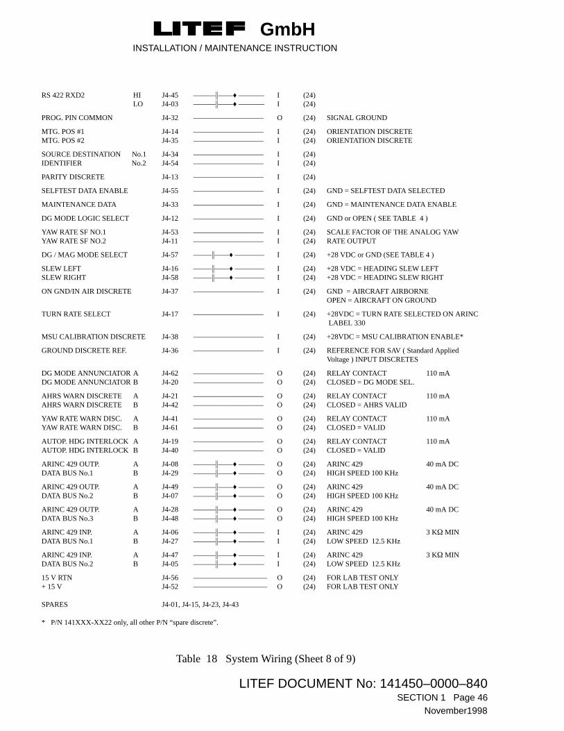
9.8 J4 (I/O) (only AHRU / PN 141450-XXXX and 141852-XXXX)
Electrical Pin AssignmentJ4 (I/O)
FUNCTION CONNECTOR PIN IN/OUT AWG SIGNAL FORMAT LOAD
MSU J4-51 ––––––�––––♦ ––––––– I (24) ANALOG SIGNAL (see Table 19)SIGNAL J4-09 ––––––�––––♦ ––––––– I (24) ANALOG SIGNAL (see Table 19)INPUT J4-30 ––––––�––––♦ ––––––– I (24) ANALOG SIGNAL (see Table 19)GND J4-50 O (24) FOR LAB TEST ONLY
MSU REFERENCE OUT J4-39 ––––––�––––♦ ––––––– O (24) CONNECT TO J4-60GND J4-59 ––––––�––––♦ ––––––– O (24) FOR LAB TEST ONLY
MSU REFERENCE IN J4-60 ––––––�––––♦ ––––––– I (24) CONNECT TO J4-39GND J4-18 ––––––�––––♦ ––––––– I (24) FOR LAB TEST ONLY
FLUX VALVE HI J4-02 ––––––�––––♦ ––––––– O (24) 7.2 - 40VRMSEXCITATION LO J4-22 ––––––�––––♦ ––––––– O (24) 400Hz (depends on MSU type)
SLAVING ERROR HI J4-10 ––––––�––––♦ ––––––– O (24) 2-WIRE DC CURRENT LO J4-31 ––––––�––––♦ ––––––– O (24) �200 �A/�15� FULL SCALE 1 K�
RS 422 TXD1 HI J4-04 ––––––�––––♦ ––––––– O (24) LO J4-25 ––––––�––––♦ ––––––– O (24)
RS 422 RXD1 HI J4-26 ––––––�––––♦ ––––––– I (24) LO J4-46 ––––––�––––♦ ––––––– I (24)
RS 422 TXD2 HI J4-24 ––––––�––––♦ ––––––– O (24) LO J4-44 ––––––�––––♦ ––––––– O (24)
Table 18 System Wiring (Sheet 7 of 9)
GmbHINSTALLATION / MAINTENANCE INSTRUCTION
LITEF DOCUMENT No: 141450–0000–840SECTION 1 Page 46
November1998
RS 422 RXD2 HI J4-45 ––––––�––––♦ ––––––– I (24) LO J4-03 ––––––�––––♦ ––––––– I (24)
PROG. PIN COMMON J4-32 ––––––––––––––––––– O (24) SIGNAL GROUND
MTG. POS #1 J4-14 ––––––––––––––––––– I (24) ORIENTATION DISCRETEMTG. POS #2 J4-35 ––––––––––––––––––– I (24) ORIENTATION DISCRETE
SOURCE DESTINATION No.1 J4-34 ––––––––––––––––––– I (24)IDENTIFIER No.2 J4-54 ––––––––––––––––––– I (24)
PARITY DISCRETE J4-13 ––––––––––––––––––– I (24)
SELFTEST DATA ENABLE J4-55 ––––––––––––––––––– I (24) GND = SELFTEST DATA SELECTED
MAINTENANCE DATA J4-33 ––––––––––––––––––– I (24) GND = MAINTENANCE DATA ENABLE
DG MODE LOGIC SELECT J4-12 ––––––––––––––––––– I (24) GND or OPEN ( SEE TABLE 4 )
YAW RATE SF NO.1 J4-53 ––––––––––––––––––– I (24) SCALE FACTOR OF THE ANALOG YAWYAW RATE SF NO.2 J4-11 ––––––––––––––––––– I (24) RATE OUTPUT
DG / MAG MODE SELECT J4-57 –––––�––––♦ –––––––– I (24) +28 VDC or GND (SEE TABLE 4 )
SLEW LEFT J4-16 –––––�––––♦ –––––––– I (24) +28 VDC = HEADING SLEW LEFTSLEW RIGHT J4-58 –––––�––––♦ –––––––– I (24) +28 VDC = HEADING SLEW RIGHT
ON GND/IN AIR DISCRETE J4-37 ––––––––––––––––––– I (24) GND = AIRCRAFT AIRBORNEOPEN = AIRCRAFT ON GROUND
TURN RATE SELECT J4-17 ––––––––––––––––––– I (24) +28VDC = TURN RATE SELECTED ON ARINC LABEL 330
MSU CALIBRATION DISCRETE J4-38 ––––––––––––––––––– I (24) +28VDC = MSU CALIBRATION ENABLE*
GROUND DISCRETE REF. J4-36 ––––––––––––––––––– I (24) REFERENCE FOR SAV ( Standard AppliedVoltage ) INPUT DISCRETES
DG MODE ANNUNCIATOR A J4-62 ––––––––––––––––––– O (24) RELAY CONTACT 110 mADG MODE ANNUNCIATOR B J4-20 ––––––––––––––––––– O (24) CLOSED = DG MODE SEL.
AHRS WARN DISCRETE A J4-21 ––––––––––––––––––– O (24) RELAY CONTACT 110 mAAHRS WARN DISCRETE B J4-42 ––––––––––––––––––– O (24) CLOSED = AHRS VALID
YAW RATE WARN DISC. A J4-41 ––––––––––––––––––– O (24) RELAY CONTACT 110 mAYAW RATE WARN DISC. B J4-61 ––––––––––––––––––– O (24) CLOSED = VALID
AUTOP. HDG INTERLOCK A J4-19 ––––––––––––––––––– O (24) RELAY CONTACT 110 mAAUTOP. HDG INTERLOCK B J4-40 ––––––––––––––––––– O (24) CLOSED = VALID
ARINC 429 OUTP. A J4-08 ––––––�––––♦ ––––––– O (24) ARINC 429 40 mA DCDATA BUS No.1 B J4-29 ––––––�––––♦ ––––––– O (24) HIGH SPEED 100 KHz
ARINC 429 OUTP. A J4-49 ––––––�––––♦ ––––––– O (24) ARINC 429 40 mA DCDATA BUS No.2 B J4-07 ––––––�––––♦ ––––––– O (24) HIGH SPEED 100 KHz
ARINC 429 OUTP. A J4-28 ––––––�––––♦ ––––––– O (24) ARINC 429 40 mA DCDATA BUS No.3 B J4-48 ––––––�––––♦ ––––––– O (24) HIGH SPEED 100 KHz
ARINC 429 INP. A J4-06 ––––––�––––♦ ––––––– I (24) ARINC 429 3 K� MINDATA BUS No.1 B J4-27 ––––––�––––♦ ––––––– I (24) LOW SPEED 12.5 KHz
ARINC 429 INP. A J4-47 ––––––�––––♦ ––––––– I (24) ARINC 429 3 K� MINDATA BUS No.2 B J4-05 ––––––�––––♦ ––––––– I (24) LOW SPEED 12.5 KHz
15 V RTN J4-56 –––––––––––––––––––– O (24) FOR LAB TEST ONLY+ 15 V J4-52 –––––––––––––––––––– O (24) FOR LAB TEST ONLY
SPARES J4-01, J4-15, J4-23, J4-43
* P/N 141XXX-XX22 only, all other P/N “spare discrete”.
Table 18 System Wiring (Sheet 8 of 9)

GmbHINSTALLATION / MAINTENANCE INSTRUCTION
LITEF DOCUMENT No: 141450–0000–840 SECTION 1 Page 47
November 1998
9.9 J5 (MSU CalPROM)
NOTE : No wiring is required for the MSU CalProm upon installation.
Electrical Pin AssignmentJ5 (MSU CalPROM)
FUNCTION CONNECTOR PIN IN/OUT AWG SIGNAL FORMAT LOAD
+5 VDC CalPROM POWER J5-01 ––––––––––––––––––– O (24) AHRU +5 VDC5 VDC RETURN J5-02 ––––––––––––––––––– I (24) DC POWER GROUND
SPROMCS J5-06 ––––––––––––––––––– O (24) TTLSTXCLK J5-05 ––––––––––––––––––– O (24) TTLSTXD J5-03 ––––––––––––––––––– O (24) TTLSRXD J5–04 ––––––––––––––––––– I (24) TTL
RS-422 TXD1 HI J5-14 ––––––�––––♦ ––––––– O (24) FOR LAB TEST ONLYLO J5-15 ––––––�––––♦ ––––––– O (24)
RS-422 RXD1 HI J5-12 ––––––�––––♦ ––––––– I (24) FOR LAB TEST ONLYLO J5-13 ––––––�––––♦ ––––––– I (24)
PROGRAM LOAD ENABLE* J5–07 ––––––––––––––––––– I (24) FOR LAB TEST ONLY
CAL.PROG. LOAD DISCR.* J5-08 ––––––––––––––––––– I (24) FOR LAB TEST ONLY
HIL TEST ENABLE* J5-09 ––––––––––––––––––– I (24) FOR LAB TEST ONLY
TIME TAG C. RESET J5-10 ––––––––––––––––––– I (24) FOR LAB TEST ONLY
SPARE J5-11
––––♦ –––– twisted wire
––––♦ ––––
––�–♦ –––– twisted and shielded wire––�–♦ ––––
Table 18 System Wiring (Sheet 9 of 9)
AHRU InputConnector Pin
Bendix./KingKMT 112
HoneywellFX-120
HoneywellFX-125
HoneywellFX-220
J4–51 A B B B
J4–09 D A A A
J4–30 B C C C
J4–02 H D D D
J4–22 E E E E
not con. F F F
Table 19 AHRU/MSU Wiring

GmbHINSTALLATION / MAINTENANCE INSTRUCTION
LITEF DOCUMENT No: 141450–0000–840SECTION 1 Page 48
November1998
Figure 13 Interconnection Diagram CCU, LCR-92
+28 VDC J1-15
J1-08
28
GND DISCRETE REF
*
* not necessary for P/N -XX11 / -XX22

GmbHINSTALLATION / MAINTENANCE INSTRUCTION
LITEF DOCUMENT No: 141450–0000–840 SECTION 1 Page 49
November 1998
Figure 14 Interconnection Diagram Ground Discrete Reference
* not necessary for P/N -XX11 / -XX22
*

GmbHINSTALLATION / MAINTENANCE INSTRUCTION
LITEF DOCUMENT No: 141450–0000–840SECTION 1 Page 50
November1998
Figure 15 Shield termination of connectors using Metal Backshell/Strain Relief method

GmbHINSTALLATION / MAINTENANCE INSTRUCTION
LITEF DOCUMENT No: 141450–0000–840 SECTION 1 Page 51
November 1998
Figure 16 Bonding Strap for the installation of AHRU P/N 141852-3211

GmbHINSTALLATION / MAINTENANCE INSTRUCTION
LITEF DOCUMENT No: 141450–0000–840SECTION 1 Page 52
November1998
THIS PAGE INTENTIONALLY LEFT BLANK

GmbHINSTALLATION / MAINTENANCE INSTRUCTION
LITEF DOCUMENT No: 141450–0000–840TITLE PAGE SECTION 2
November 1998
SECTION 2
DESCRIPTION AND OPERATION

GmbHINSTALLATION / MAINTENANCE INSTRUCTION
LITEF DOCUMENT No: 141450–0000–840SECTION 2 Page 1
November 1998
1 General
This section provides on-aircraft maintenance procedures for the LCR-92 Attitude and HeadingReference System (AHRS). A system consists of an Attitude and Heading Reference Unit (AHRU), aMagnetic Sensor Unit (MSU) and, optionally, a compass controller unit (CCU).
Section 1, Installation Instructions, contains information that can be pertinent to on-aircraft maintenanceof the AHRS; that information should be used in conjunction with this section when applicable.
2 Purpose of Equipment
The LCR-92 Attitude and Heading Reference System (AHRS) is an all attitude inertial sensor systemwhich provides aircraft attitude, heading and flight dynamics information to display, flight control,weather radar antenna platform and other aircraft systems and instruments.
3 Leading Particulars
Leading particulars for the AHRS are provided in Section 1, Paragraph 1, Installation Data.
4 Description
Descriptive information pertaining to the AHRS units is provided in the following Paragraphs:
4.1 Location of Units in Aircraft.
Provided in Section 1, Paragraph 1.2, Installation Data.
4.2 Outline and Mounting Drawings
Outline and mounting drawings for the AHRU, MSU, CCU, AHRU trays and CalPROM are provided inFigures 3 through 12 of section 1.
4.3 AHRU
The LCR-92 is mechanized as a strapdown inertial measurement system using fiber optic rate gyroswhich are ”strapped down” to the aircraft axes. A digital computer mathematically integrates the ratedata to obtain heading, pitch and roll. A flux valve (MSU) and one dual axis level sensor provide longterm references for the system.

GmbHINSTALLATION / MAINTENANCE INSTRUCTION
LITEF DOCUMENT No: 141450–0000–840SECTION 2 Page 2
November 1998
4.4 MSU
The magnetic sensor unit detects the horizontal component of the earth’s magnetic field and transmits itto the AHRU for use as long term correction information.
4.5 CCU (Optional)
The CCU contains controls and annunciators to facilitate manual slaving of the AHRU to the MSU andprovides the following additional capabilities to the AHRS:
– Slaved or free gyro (DG) operation mode selection..
– Setting of compass heading during free gyro (DG) mode operation.
– Fast slaving during operation at extreme latitudes.
– Nulling of compass error after alignment in areas of high magnetic disturbances.
The CCU allows crew selection of either DG or slaved magnetic modes. A slaving error annunciator andslew switch are provided for setting the compass heading in DG mode and to provide an indication ofsynchronization in slaved magnetic mode. The slew switch may also be used to manually correctheading information during operation in extreme latitudes.
5 Modes of Operation
The AHRS provides the following modes of operation:
* Alignment (On ground or in air)
* Normal Mode – Slave Mode (Valid MSU data)
– DG Mode (MSU data not valid or manually selected DG Mode)
* MSU Calibration Mode
* Maintenance Mode

GmbHINSTALLATION / MAINTENANCE INSTRUCTION
LITEF DOCUMENT No: 141450–0000–840 SECTION 2 Page 3
November 1998
5.1 Alignment
5.1.1 General
Following initial power application, the system performs an alignment sequence which consists of twoalignment phases. During the alignment sequence, the attitude and heading warn discretes are set to warncondition and bits 15 and 11 are set in Label 270 of the DITS (Digital Information Transfer System)output, together with no computed data (NCD) in Label 320 to 325.
After short power interrupts (duration less than 500 ms) the AHRS provides a short initializationsequence which results in valid attitude, heading and rate data after less than 45 ms. Power interruptslonger than 500 ms will result in an IN AIR Alignment
5.1.2 Alignment Phase 1
The minimum duration of alignment phase 1 is 15 seconds whether the aircraft is on ground or in air. Ifthe system ambient temperature is outside the range of +15�C to +35�C, the duration may increase up to30 seconds.
During alignment phase 1, the analog outputs are set to zero, thereafter the actual computed values areoutput on the synchro and AC outputs of pitch, roll and heading. However, the discrete valids are set tovalid only after the successful completion of the alignment phase 2.
The DITS outputs of pitch, roll and yaw rate as well as the analog output of yaw and turn rates are validafter completion of alignment phase 1.
5.1.3 Alignment Phase 2
For static conditions this mode lasts 15 seconds (after phase 1). Static conditions are defined as follows:
On Ground Alignment
The aircraft has to be stationary for the first 30 seconds after power-on. However, wind buffeting, cargoloading etc. does not affect the alignment duration.
In order to lower the heading drift in DG-Mode, the earth rate and gyro drift are estimated during andafter alignment. The maximum estimation time is 120 seconds, if no excessive motion has been detected.The estimated value is stored after 120 seconds and the AHRU takes this value for initialization of thenext estimation..

GmbHINSTALLATION / MAINTENANCE INSTRUCTION
LITEF DOCUMENT No: 141450–0000–840SECTION 2 Page 4
November 1998
In Air Alignment
The aircraft has to be flying under straight and level flight conditions for the alignment period. Undernormal flight conditions with moderate turbulance alignment will not take longer than 2 minutes.
When excessive motion is detected the AHRS is switched automatically to the moving alignmentsequence. In this sequence the completion of attitude and heading alignment depends on internalcalculated parameters, which indicate a sufficient alignment accuracy. After both have been set validalignment phase 2 is completed.
After successful completion of alignment phase 2 all output data are set valid and the accuraciesspecified are applicable.
5.2 Normal Mode
5.2.1 Slave Mode
In Slave Mode the system heading loop is supplied with valid MSU data.
5.2.2 DG Mode
The Directional Gyro Mode can be activated manually by the DG Mode Select discrete.
5.3 MSU Calibration Mode
The MSU calibration mode is manually selected by the MSU calibration control switch. In MSUcalibration mode the system determines the MSU calibration coefficients. After successful calibrationthe coefficients will be stored in the MSU Calibration PROM. Details are given in Section 1, Paragraph7.
5.4 Maintenance Mode
5.4.1 General
The Maintenance Mode is manually selected by the maintenance control discrete, which has to be setbefore power–on.
The only output of the system in the maintenance mode is the failure history and the elapsed timerecorded by the elapsed time counter implemented in the software.
The maintenance mode is enabled, if the aircraft is determined to be on the ground by the GND/AirControl Discrete.

GmbHINSTALLATION / MAINTENANCE INSTRUCTION
LITEF DOCUMENT No: 141450–0000–840 SECTION 2 Page 5
November 1998
5.4.2 Failure Logging and Malfunction Storage
The AHRS provides the capability for recording failure data. This is achieved by storing failuremaintenance data in labels 350, 351, 352 and 353 in the EEPROM.
The EEPROM area is subdivided into records, each record consisting of the labels 350, 351, 352 and353. The System will initialize the EEPROM at turn-on to determine which record should be used for thecurrent power-on phase (logic has been implemented to differentiate between a short power interruptand a new turn-on to determine if re-initialization is necessary).
The System also periodically monitors the state of maintenance words to see if any new failure hasoccured. All data are latched in the EEPROM (if an intermittent failure disappears, the record of itsoccurence will not be removed).
After a successful completion of a repair the stored failure data in the EEPROM can be erased by specialtest equipment.
The failure memory is capable of storing up to 192 failure records. The oldest failure records will beoverwritten, if more than 192 failure records are recorded.
5.4.3 Output of the Failure History and Elapsed Time
If the system is in Maintenance Mode (maintenance data discrete is set) the failure history and elapsedtime will be provided via the RS-422 output interface 1. The elapsed time counter has a range in excess of100,000 hours. PNs 141XXX-XX22 provide the maintenance data on the ARINC 429 bus also.
NOTE: P/N 124210-XX00 does not provide the elapsed time information.
The data are transmitted cyclicly starting with the accumulated operating hours followed by the mostrecent failure record. After all records have been transmitted the program waits for one second beforerepeating the output.
The following table defines the transmission frame of the output. The LSB of the elapsed time readout isequal to 0.1h. The significant 16 bits of each maintenance word will be transmitted only. The checksumis the ones complement of the word wise accumulation of the preceding 4 words (respectively 2 wordsfor the elapsed time) and the record number.

GmbHINSTALLATION / MAINTENANCE INSTRUCTION
LITEF DOCUMENT No: 141450–0000–840SECTION 2 Page 6
November 1998
1. Record Upper Byte of Record Number “0”
Lower Byte of Record Number “0”
Bit 32-Bit 25 of elapsed time
Bit 24-Bit 17 of elapsed time
Bit 16-Bit 09 of elapsed time
Bit 08-Bit 01 of elapsed time
Upper Byte of Checksum
Lower Byte of Checksum
2. Record Upper Byte of Record Number “n”
Lower Byte of Record Number “n”
Bit 29-Bit 22 of Label 350
Bit 21-Bit 14 of Label 350
Bit 29-Bit 22 of Label 351
Bit 21-Bit 14 of Label 351
Bit 29-Bit 22 of Label 352
Bit 21-Bit 14 of Label 352
Bit 29-Bit 22 of Label 353
Bit 21-Bit 14 of Label 353
Bit 32-Bit 25 of elapsed time @ failure condition*
Bit 24-Bit 17 of elapsed time @ failure condition*
Bit 16-Bit 09 of elapsed time @ failure condition*
Bit 08-Bit 01 of elapsed time @ failure condition*
Upper Byte of Checksum
Lower Byte of Checksum
* the time tag in case of a Bite entry into memory is utilised in P/N 141XXX-XX22
Table 1 Failure Transmission Frame (Sheet 1 of 2)
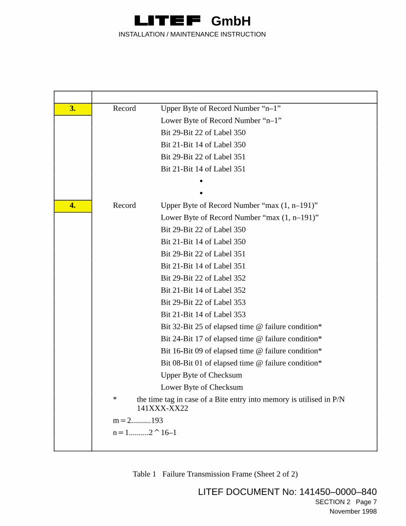
GmbHINSTALLATION / MAINTENANCE INSTRUCTION
LITEF DOCUMENT No: 141450–0000–840 SECTION 2 Page 7
November 1998
3. Record Upper Byte of Record Number “n–1”
Lower Byte of Record Number “n–1”
Bit 29-Bit 22 of Label 350
Bit 21-Bit 14 of Label 350
Bit 29-Bit 22 of Label 351
Bit 21-Bit 14 of Label 351
�
�
4. Record Upper Byte of Record Number “max (1, n–191)”
Lower Byte of Record Number “max (1, n–191)”
Bit 29-Bit 22 of Label 350
Bit 21-Bit 14 of Label 350
Bit 29-Bit 22 of Label 351
Bit 21-Bit 14 of Label 351
Bit 29-Bit 22 of Label 352
Bit 21-Bit 14 of Label 352
Bit 29-Bit 22 of Label 353
Bit 21-Bit 14 of Label 353
Bit 32-Bit 25 of elapsed time @ failure condition*
Bit 24-Bit 17 of elapsed time @ failure condition*
Bit 16-Bit 09 of elapsed time @ failure condition*
Bit 08-Bit 01 of elapsed time @ failure condition*
Upper Byte of Checksum
Lower Byte of Checksum
* the time tag in case of a Bite entry into memory is utilised in P/N 141XXX-XX22
m�2..........193
n�1..........2�16–1
Table 1 Failure Transmission Frame (Sheet 2 of 2)

GmbHINSTALLATION / MAINTENANCE INSTRUCTION
LITEF DOCUMENT No: 141450–0000–840SECTION 2 Page 8
November 1998
6 Power Interruptions
6.1 General
During power interruptions (less than 13.5 VDC), the system switches off immediately (< 20ms). Oncethe power returns the system automatically switches on, and depending on various criteria, there are twosystem responses. Initialization is performed after a short power interrupt, which is designed to restorethe system to valid operation 45 milliseconds after the input voltage is greater than the 18 VDCthreshold. For a long power interrupt a complete realignment is initiated.
6.2 Short Power Interrupt
Duration: less than or equal to 445 milliseconds.
System response: Fast initialization giving valid operation within 45 msec of power reaching the 18VDC threshold. For example, after a power interrupt of 50 msec in duration, theAHRS will output valid ARINC 429 data, synchro outputs and flags 95 msec afterthe start of power interrupt. The SSM after the interrupt is the same as before theinterrupt unless the system status changed during the interrupt.
6.3 Long Power Interrupt
Duration: more than 600 milliseconds.
System response: Normal turn-on sequence initiated with complete realignment as per paragraph5.1. Interrupt duration between 445 and 600 msec may result in the first or secondresponse due to hardware component tolerances.

GmbHINSTALLATION / MAINTENANCE INSTRUCTION
LITEF DOCUMENT No: 141450–0000–840TITLE PAGE SECTION 3
November 1998
SECTION 3
TESTING AND TROUBLESHOOTING


GmbHINSTALLATION / MAINTENANCE INSTRUCTION
LITEF DOCUMENT No: 141450–0000–840SECTION 3 Page 1
November 1998
1 General
A typical AHRS installation is shown in the block diagram of Figure 1 of Section 3. Depending on theaircraft avionics system configuration one or two AHRUs may be installed.
No manual testing of the AHRS is required, and troubleshooting is simplified by the built-in faultmonitoring and self-test circuits of the AHRU. When power is applied to the system, a series of self-testsare performed to verify system functions. In addition, the system contains hardware and softwaremonitors and performs continuous background hardware and software verification tests. Failure of thesetests results in output of warn signals or system shutdown. The Maintenance Discrete Output words areshown in Tables 1 through 4. Heading Fail, Attitude Fail, Yaw Rate Fail and Turn Rate Fail warningsignals will set flags on the aircraft flight displays. The AHRS Fail warning signal provides a failwarning output any time one of the basic display warnings is set. This AHRS Fail warning can be used inconjunction with the MASTER WARNING display system.
Manually initiated self-tests can also be performed on each of the individual AHRUs. Self-test discretes,one for each of the AHRUs, are provided for implementation. Actuation of the discrete causes that unit tooutput test values to the aircraft systems. The parameters output and the associated test values are shownin Section 1, Paragraph 4.3. A chart of fault monitoring provisions is included in Tables 1 through 4 ofSection 3.
The fault history of the AHRU may be accessed by using LITEF LCR-92 Level 1 Test Set 309444, or anyother commercially available data download equipment. More details are laid out in paragraph 4 of thissection.
NOTEParagraph 3 shows the check-list for the steps to be followed, when a fault appears during an initial installation of a system. Likewise, the check-list may also be consulted as a fault finding guide during the time that the equipment is in service.

GmbHINSTALLATION / MAINTENANCE INSTRUCTION
LITEF DOCUMENT No: 141450–0000–840SECTION 3 Page 2
November 1998
Figure 1 Typical LCR-92 AHRS Installation
FLIGHT
MANAGEMENT
SYSTEM
FLIGHT
DATA
RECORDER
E
E

GmbHINSTALLATION / MAINTENANCE INSTRUCTION
LITEF DOCUMENT No: 141450–0000–840 SECTION 3 Page 3
November 1998
2 Maintenance Discrete Outputs
DITS labels 350 - 353 contain discrete information to assist in fault finding. This information representsthe actual failure status of the system and will be provided during normal operation.
The following tables define the allocation of these bits.
MAINTENANCE DISCRETE WORD 1, Label 350
BIT No. FUNCTION POSSIBLE CAUSE ACTION NOTE
1 - 13 not applicable
14 RAM fail AHRU defective return AHRU for repair
15 EEPROM fail AHRU defective return AHRU for repair
16 MSU CalPROM fail CalPROM not installed
CalPROM defectiveAHRU defective
check installation, check CalPROM connectors.replace CalPROMreturn AHRU for repair
1
17 Program cycle fail AHRU defective return AHRU for repair
18 Scheduler fail AHRU defective return AHRU for repair
19 Real Time Interrupt fail AHRU defective return AHRU for repair
20 Watch Dog Timer fail AHRU defective return AHRU for repair
21 Power Interrupt Timer fail AHRU defective return AHRU for repair
22 Misalignment CalPROM fail CalPROM not installedCalPROM defectiveCalPROM incorrectlyprogrammedAHRU defective
check installation,replace and/or reprogram,reprogram
return AHRU for repair
1(after replace-ment)
23 Processor Test fail AHRU defective return AHRU for repair
24 not applicable
25 EEPROM Access fail AHRU defective return AHRU for repair
26 not applicable
27 Fan Supply Monitor insufficient or excessivecurrent to Fan
check wiring, and supply toFan, check power consumption,check voltage between pin J2-3and J2-2 for 24V/50mA.check wiring and/or connectorpinsreturn AHRU for repair
28 - 29 not applicable
30 - 31 SSM (always 0)
32 Odd Parity
Table 1 Maintenance Discrete Outputs (Label 350)

GmbHINSTALLATION / MAINTENANCE INSTRUCTION
LITEF DOCUMENT No: 141450–0000–840SECTION 3 Page 4
November 1998
MAINTENANCE DISCRETE WORD 2, Label 351
BIT No. FUNCTION POSSIBLE CAUSE ACTION NOTE
1 - 13 not applicable
14 FOG auxiliary control loop fail 1 AHRU defective return AHRU for repair
15 FOG auxiliary control loop fail 2 AHRU defective return AHRU for repair
16 FOG Signal Noise Test AHRU defective return AHRU for repair
17 Max. Angular Rate exceeded Excessive rates duringflightAHRU defective
check flight profile
return AHRU for repair
18 Temp. Sensor fail AHRU defective return AHRU for repair
19 Sensor max. temp. exceeded Excessive temperaturesduring operationAHRU defective
check ambient temperatures
return AHRU for repair
20 Level Sensor fail Excessive vibration
AHRU defective
check fixture/AHRU/tray (eg.screws insecure)return AHRU for repair
21 Attitude Plausibility Test Excessive dynamics forextended periods,Excessive drift
check flight profile
return AHRU for repair
22 Sensor MUX/ADC fail(instrument failure)
AHRU defective return AHRU for repair
23 MSU Data fail MSU not installed,no MSU data in/out,
AHRU defective
check installationcheck wiring/connectorscheck flux-valvereturn AHRU for repair
24 - 29 not applicable
30 - 31 SSM (Always 0)
32 Odd parity
Table 2 Maintenance Discrete Outputs (Label 351)

GmbHINSTALLATION / MAINTENANCE INSTRUCTION
LITEF DOCUMENT No: 141450–0000–840 SECTION 3 Page 5
November 1998
MAINTENANCE DISCRETE WORD 3, Label 352
BIT No. FUNCTION POSSIBLE CAUSE ACTION NOTE
1 - 13 not applicable
14 DITS self-test fail AHRU defective return AHRU for repair
15 DITS transmitter not ready AHRU defective return AHRU for repair
16 DITS wrap-around fail AHRU defective return AHRU for repair
17 Analogue/Digital Converterfail (I/O)
AHRU defective return AHRU for repair
18 Slaving error DAC referencefail
AHRU defective return AHRU for repair
19 Discrete output fail (I/O) AHRU defective return AHRU for repair
20 MSU reference not available no input signal at J4-60available
AHRU defective
check availability of jumperJ4-39 to J4-60,check signal at J4-60 for 800Hz and 2.5Vrms,return AHRU for repair
21 Program Pin Monitor Incorrect or brokenwiring Parity not odd,AHRU defective
rectify i. a. w. Section 1, paragraph 3.1.1.check Parity statusreturn AHRU for repair
22 not applicable
23 Heading Plausibility Test fail Flux-valve not calibratedFlux-valve defectiveFlux-valve installationfaulty
AHRU defective
calibrate flux-valve,
replace flux-valvecheck installation
return AHRU for repair
24 - 29 not applicable
30 - 31 SSM (always 0)
32 Odd parity
Table 3 Maintenance Discrete Outputs (Label 352)

GmbHINSTALLATION / MAINTENANCE INSTRUCTION
LITEF DOCUMENT No: 141450–0000–840SECTION 3 Page 6
November 1998
MAINTENANCE DISCRETE WORD 4, Label 353
BIT No. FUNCTION POSSIBLE CAUSE ACTION NOTE
1 - 13 not applicable
14 Attitude reference unavailable no external input check wiring to/from 400 Hzsource and AHRU
3
15 Heading reference 1 unavailable no external input(broken wire(s))AHRU defective
check wiring to/from 400 Hzsource and AHRUreturn AHRU for repair
3
16 Heading Synchro 1 fail AHRU defective return AHRU for repair
17 Roll Synchro fail short circuit in wiring,AHRU defective
check wiring to/from synchros.return AHRU for repair
18 Pitch Synchro fail short circuit in wiring,AHRU defective
check wiring to/from synchros.return AHRU for repair
19 Yaw Rate DC output fail short circuit in wiring,AHRU defective
check wiring to/from synchros.return AHRU for repair
20 Turn Rate DC output fail short circuit in wiring,AHRU defective
check wiring to/from synchros.return AHRU for repair
21 Discrete output fail AHRU defective return AHRU for repair
22 Heading Synchro 2 fail AHRU defective return AHRU for repair 2
23 Heading reference 2 unavailable no external input,(broken wire(s)),AHRU defective
check wiring to/from 400 Hzsource and AHRU.return AHRU for repair
3
24 - 29 not applicable
30 - 31 SSM (Always 0)
32 Odd parity
Table 4 Maintenance Discrete Outputs (Label 353)
NOTE1) Recalibrate AHRU/CalPROM, if CalPROM was replaced2) applicable for PN XXXXXX-3XXX only3) not stored into the malfunction memory

GmbHINSTALLATION / MAINTENANCE INSTRUCTION
LITEF DOCUMENT No: 141450–0000–840 SECTION 3 Page 7
November 1998
3 Initial Installation of an AHRU Fault Finding Check-list
During the first integration testing of an AHRU, or a fault symptom shows during subsequent tests, thefault should be analysed in accordance with the following check-list. Note that some of the steps statethat an EFIS is part of the system, but it could well be that an operator has another form ofinstrument display panel, eg. HSI / EHSI, etc. Therefore this must be taken into considerationwhen working through the steps.
AHRS EQUIPPED WITHOUT A SYNCHRO CARD
3.1 STEP 1 : EFIS DOES NOT DISPLAY ANY DATA
POWER Check pins J1- 01/09 (28VDC) and J1-02/10 (28V RTN).
ARINC Check A/B TRX wiring to EFIS for correct termination of A (J4-08) and B (J4-29) wires.
After both checks prove correct, and power is available to the AHRU and EFIS, then data must bedisplayed (although the EFIS may still display invalid data.). If fault still apparent, further investigationof the AHRS and/or EFIS must be carried out.
3.2 STEP 2 : HEADING AND ATTITUDE FLAGS DISPLAYED (invalid data)
Heading and Attitude are set to valid after approximately 30 seconds after power is applied to the AHRSand a ground alignment is initiated. If not :
Check MSU Calibration Switch is in the OFF position.
CalPROM A CalPROM must be installed and connected to 1J5.
After this check proves correct, the AHRS will set Heading and Attitude flags valid after approximately30 seconds. If fault still apparent, further investigation of the AHRU must be carried out.
3.3 STEP 3 : HEADING FLAG DISPLAYED (invalid data)
Flux–valve Check if the correct type of flux–valve is fitted and connected. Check if the wiring is correct. 2 wires from AHRU (J4-02 and J4-22) to flux-valve (FV), and 3 wires from FV to AHRU (J4-51, J4-09 and J4-30).Check if MSU REF. IN (J4-60) is connected to MSU REF. OUT (J4-39).
After these checks prove correct, the heading flag will be set to valid after approximately 30 secondsafter alignment is initiated. If fault still apparent, further investigation of the AHRU must be carried out.

GmbHINSTALLATION / MAINTENANCE INSTRUCTION
LITEF DOCUMENT No: 141450–0000–840SECTION 3 Page 8
November 1998
3.4 STEP 4 : ATTITUDE FLAG DISPLAYED (invalid data)
Attitude is set to valid after approximately 30 seconds if an on the ground alignment (eg. after power-on)is commanded.
CalPROM A CalPROM must be installed and connected to 1J5.
Parity pin Check equation to program Parity pin (section 1, paragraph 3.1.1).
3.5 STEP 5 : HEADING CHECK
Check that when A/C is aligned to North the heading displays 0� �5� after alignment. If not check excitation voltage and/or signal wiring.Turn A/C to align with East and check that the heading displays 090� �5�.If not check excitation voltage and/or signal wiring
NOTEAfter alignment the A/C may be turned to any HDG, and the displayed heading must correspondto the A/C heading �5�.
3.6 STEP 6 : ATTITUDE CHECK
Tilt AHRU right wing (starboard) down / up and check attitude display.Tilt AHRU nose up / nose down and check attitude display.
3.7 STEP 7 : CCU CHECK
Set CCU to DG-Mode. EFIS should display that AHRU is in DG-Mode. Turn knob clockwise to command “SLEW RIGHT” and check heading increases.Turn knob counterclockwise to command “SLEW LEFT” and check heading decreases.
3.8 STEP 8 : SELF-TEST
Activate Self-Test and check that AHRU outputs displays of heading (15�), pitch (+5�) and roll (45�right wing down), 180�/min. Rate of Turn, ATT, HDG and T/R flags, (refer to section 1, paragraph 4.3).

GmbHINSTALLATION / MAINTENANCE INSTRUCTION
LITEF DOCUMENT No: 141450–0000–840 SECTION 3 Page 9
November 1998
3.9 STEP 9 : MSU CAL-MODE SWITCH
Set MSU CAL-MODE switch to ON.Check that attitude and heading flags are displayed, and after approximately 10 to 20 seconds the heading flag disappears (set valid).Set MSU CAL-MODE switch to OFF.
3.10 STEP 10 : ON GROUND / IN AIR SWITCH
Set all switches to normal operation, that is :CAL-MODE OFF,SELF-TEST OFF,DG /MAG to MAG,
Set ON GROUND / IN AIR switch to IN AIR. Set SELF-TEST to ON
NOTEThe Self-Test is disabled if the A/C is IN AIR switch position, therefore the self-test data is notdisplayed,
Set SELF-TEST to OFFIf all these tests are passed sucessfully then the AHRU may be assumed to function correctly.
AHRS EQUIPPED WITH A SYNCHRO CARD
If an AHRS is equipped with a synchro card (cable to J3 connected) the following check must be done ;Check that attitude (1x) and heading (1x or 2x) synchro outputs are connected to the synchro inputs.

GmbHINSTALLATION / MAINTENANCE INSTRUCTION
LITEF DOCUMENT No: 141450–0000–840SECTION 3 Page 10
November 1998
4 LITEF LCR-92 Level 1 Test Set
The interface may be operated using the LITEF LCR-92 Level 1 RTS Test Set 309444. The Level 1 TestSet provides the infrastructure required to perform an access to the LCR BITE history and to the AHRSmounting misalignment correction parameters. In other words it is a tool for storing the BITE recordsinto file and is then able to display on a screen the BITE history information. It also enables a stimulationof the AHRS analogue interfaces to be performed (only -2XXX and -3XXX versions).
The mounting misalignment correction feature is not available for LCR-92, P/N 124210.
ITEM LIST
The Level 1 Test Set consists of the following LITEF and commercial parts. To operate the Level 1 TestSet an IBM compatible PC is required as stated under Hardware requirements.
LITEF Parts P/N 309344 J1 AdapterP/N 309345 J4 AdapterP/N 309343 J5 Adapter P/N 309446 Serial Interface CableP/N 309356-100-701 Level 1 Test Software Disk
Commercial PartsP/N 450910-4535 RS232 - RS422 Converter P/N 450910-3173 DB9S - DB25P RS232 - Adapter
Hardware requirementsTo operate the Level 1 Test Set the following hardware is required :IBM compatible PC/AT (486DX33 or higher recommended)VGA Graphics Adapter1 Serial Communication Adapter (COM1:)Hard disk with at least 1 MByte free disk space550 kByte of available (free) Base MemoryDOS 5.0 or higher
NOTEAt various parts of this IMI a NOTE is inserted which states that the interface may be operatedusing the LITEF LCR-92 Level 1 Test Set 309444. These details laid out here are an aid to help thetechnician when fault finding, or using the Test Set in general.

GmbHINSTALLATION / MAINTENANCE INSTRUCTION
LITEF DOCUMENT No: 141450–0000–840TITLE PAGE SECTION 4
November 1998
SECTION 4
REMOVAL / INSTALLATION


GmbHINSTALLATION / MAINTENANCE INSTRUCTION
LITEF DOCUMENT No: 141450–0000–840SECTION 4 Page 1
November 1998
1 General
This section provides removal and installation procedures for the AHRU. The AHRU may be located inthe aircraft electronics rack or in an avionics bay.
Handle Units with care at all times. Mis-handling could cause damage to sensitive components ofthe AHRU.
CAUTION: To prevent possible damage to the AHRS, always pull all AHRS-related aircraftcircuit breakers out (off) before removing any unit.
2 Removal of AHRU
1. Pull all AHRU-related circuit breakers out (off).
2. Disconnect 1J1 through 1J5. (Leave CalPROM secured to the mounting tray by theretaining nylon-strap).
3. Loosen self-torquing hold-down fastener securing AHRU in mounting tray by turningcounterclockwise.
4. Grasp AHRU, lift slightly (but enough, so that the rear end will clear the hold-downfastener) and pull unit straight out from mounting tray.
3 Installation of AHRU
CAUTION: When performing the following step, do not use sharp-pointed tools to pry out theplug caps because the tools may pierce the plug cap and damage the connector pins.
1. Remove cap plugs from AHRU external connectors.
CAUTION: Failure to perform the following step may cause damage to the AHRU connectorsand/or mating connectors.
2. Ensure that all connector pins are undamaged and straight, and that no foreign objectsare in AHRU connectors and/or mating connectors.
3. Ensure that all AHRS-related circuit breakers are off.
4. Ensure that no tools or other items are in mounting tray or plenum.
5. Slide AHRU into mounting tray, carefully.
6. Engage hold-down fastener.

GmbHINSTALLATION / MAINTENANCE INSTRUCTION
LITEF DOCUMENT No: 141450–0000–840SECTION 4 Page 2
November 1998
7. Tighten self-torquing hold-down fastener by turning clockwise.
8. Connect 1J1 through 1J5. (When the CalPROM is re-attached to J5 the existingcompass compensation and mounting alignment correction constants are supplied tothe replacement AHRU)

GmbHINSTALLATION / MAINTENANCE INSTRUCTION
LITEF DOCUMENT No: 141450–0000–840TITLE PAGE SECTION 5
November 1998
SECTION 5
STORAGE / PACKAGING / TRANSPORTATION


GmbHINSTALLATION / MAINTENANCE INSTRUCTION
LITEF DOCUMENT No: 141450–0000–840SECTION 5 Page 1
November 1998
1 General
This section provides storage, packaging and transportation procedures for the AHRU. The procedurescontain recommended specifications, but their use is not mandatory.
Handle Units with care at all times. Mis-handling could cause damage to sensitive components ofthe AHRU.
2 Storage
The LCR-92 shall be stored in a dry dust free area. Dust free conditions can be ensured by storing theLCR-92 in the original shipping container.
3 Packaging (References in accordance with ATA 300)
NOTE : Items subjected to electrostatic damage shall be packaged in anti-static containers or wraps.
All repairable items which may be removed from the aircraft and economically restored to a fullyserviceable condition shall be shipped to an airline customer in reusable containers. This requirement isspecified because of the need to protect the item through shipment, handling, and storage up to themoment of installation, and to repeat the cycle for the life of the item.
For the purpose of this specification, reusable shipping containers are designated as follows:
Category 1 Reusable for a minimum of 100 round-tripsCategory 2 Reusable for a minimum of 10 round-tripsCategory 3* Reusable for a minimum of 1 round-trip
(when used for repairable parts, refer to chapter 8 of ATA 300)
* applicable to LCR-92.
The above categories are differentiated by materials used in the container construction and testsdescribed in specification ATA 300.
Consideration of the special packaging, shipping, handling and storage aspects of components shall beprovided by the manufacturer because of its superior knowledge of its products.This information shouldbe made available sufficiently in advance of delivery of the unit to the customer to permit orderlyphysical and financial planning. This information shall include shock sensitivity. magnetic fieldsensitivity, hazardous materials classification, electrostatic discharge sensitivity, etc.
Manufacturers shall publish and provide size (length, width and depth or detailed outline drawingsshowing all external dimensions if required due to a peculiar part configuration) and gross weight alongwith any applicable information required.
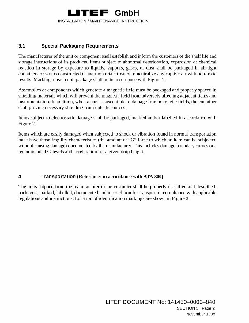
GmbHINSTALLATION / MAINTENANCE INSTRUCTION
LITEF DOCUMENT No: 141450–0000–840SECTION 5 Page 2
November 1998
3.1 Special Packaging Requirements
The manufacturer of the unit or component shall establish and inform the customers of the shelf life andstorage instructions of its products. Items subject to abnormal deterioration, coprrosion or chemicalreaction in storage by exposure to liquids, vapours, gases, or dust shall be packaged in air-tightcontainers or wraps constructed of inert materials treated to neutralize any captive air with non-toxicresults. Marking of each unit package shall be in accordance with Figure 1.
Assemblies or components which generate a magnetic field must be packaged and properly spaced inshielding materials which will prevent the magnetic field from adversely affecting adjacent items andinstrumentation. In addition, when a part is susceptible to damage from magnetic fields, the containershall provide necessary shielding from outside sources.
Items subject to electrostatic damage shall be packaged, marked and/or labelled in accordance withFigure 2.
Items which are easily damaged when subjected to shock or vibration found in normal transportationmust have those fragility characteristics (the amount of “G” force to which an item can be subjectedwithout causing damage) documented by the manufacturer. This includes damage boundary curves or arecommended G-levels and acceleration for a given drop height.
4 Transportation (References in accordance with ATA 300)
The units shipped from the manufacturer to the customer shall be properly classified and described,packaged, marked, labelled, documented and in condition for transport in compliance with applicableregulations and instructions. Location of identification markings are shown in Figure 3.

GmbHINSTALLATION / MAINTENANCE INSTRUCTION
LITEF DOCUMENT No: 141450–0000–840 SECTION 5 Page 3
November 1998
Figure 1 Packaging of Electrostatic Discharge Sensitive Devices

GmbHINSTALLATION / MAINTENANCE INSTRUCTION
LITEF DOCUMENT No: 141450–0000–840SECTION 5 Page 4
November 1998
Figure 2 Electrostatic Discharge Sensitive Device Labels (typical examples)

GmbHINSTALLATION / MAINTENANCE INSTRUCTION
LITEF DOCUMENT No: 141450–0000–840 SECTION 5 Page 5
November 1998
Figure 3 Location of Identification Markings

GmbHINSTALLATION / MAINTENANCE INSTRUCTION
LITEF DOCUMENT No: 141450–0000–840SECTION 5 Page 6
November 1998
THIS PAGE INTENTIONALLY LEFT BLANK

GmbHINSTALLATION / MAINTENANCE INSTRUCTION
LITEF DOCUMENT No: 141450–0000–840TITLE PAGE APPENDIX 1
November 1998
APPENDIX 1
RTCA/DO-160C ENVIRONMENTAL QUALIFICATION FORM


GmbHINSTALLATION / MAINTENANCE INSTRUCTION
LITEF DOCUMENT No: 141450–0000–840APPENDIX 1 Page 1
November 1998
.
RTCA/DO-160C ENVIRONMENTAL QUALIFICATION FORM
PNs XXXXXX-XX00
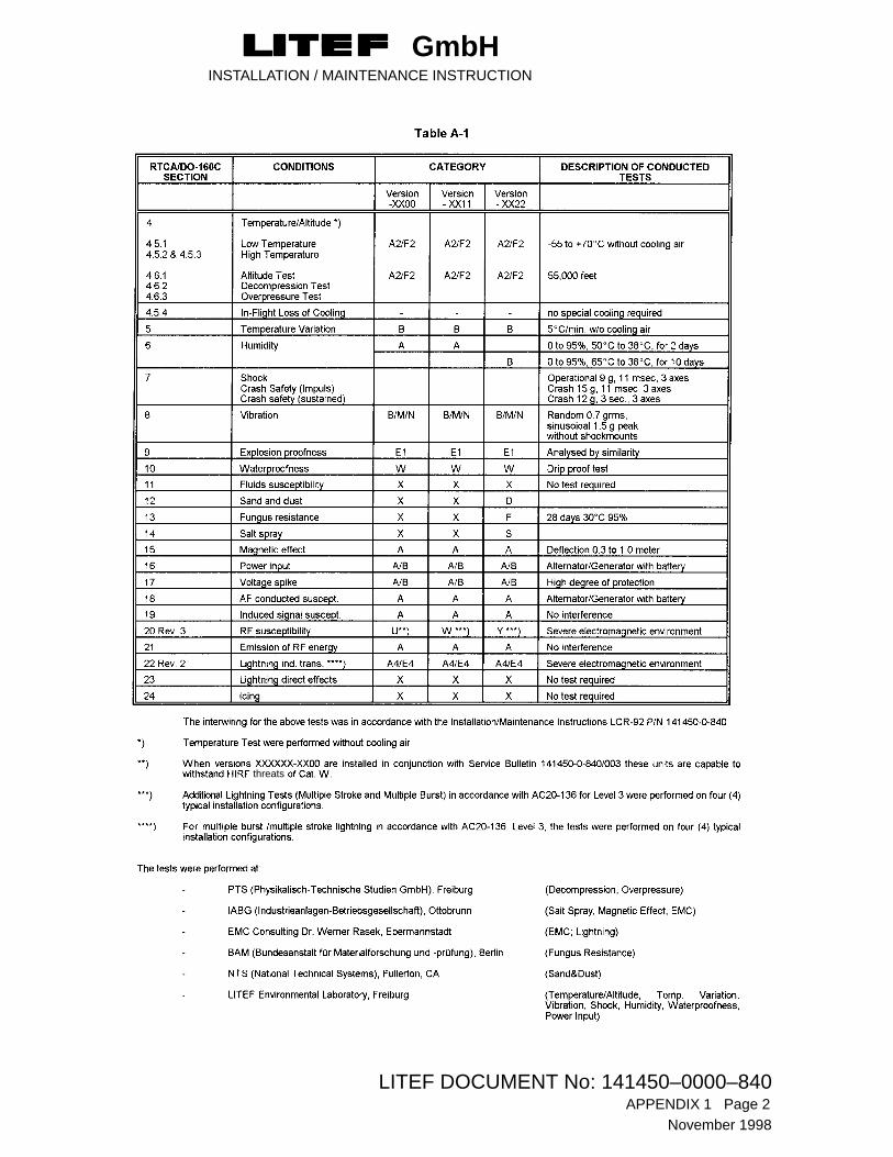
GmbHINSTALLATION / MAINTENANCE INSTRUCTION
LITEF DOCUMENT No: 141450–0000–840APPENDIX 1 Page 2
November 1998
threats