Embed Size (px)
Citation preview

1
Laser Toner Fusion: An Imaging Process forGraphic Arts Applications
William Mey* and Dennis R. Kamp**Torrey Pines Research* and NexPress Solutions LLC**
Rochester, New York
Abstract
Laser-toner-fusion (LTF) is a dry, high-qualityelectrothermographic imaging process for producing imagesfrom electronic input. The process steps involve using amagnetic brush to apply a uniform toner layer to a substrate,imagewise exposing the layer to a high power IR laser,which tacks the toner to the substrate, removing theunexposed toner using a magnetic brush toner removaldevice and finally, fixing the image using conventionalfusing. The removed unexposed toner can be recycledthereby eliminating waste. The exposed toner particles arepartially buried in a thermoplastic layer and are thereforerobust to abrasion. The process is insensitive to visibleradiation and can be carried out in ordinary roomlights. Theenergy required for imaging is between 150 and 300mJ/cm2. The application most thoroughly investigated isimagesetting where color separations with 2540 pixels perinch resolution, and with transmission density of 4.0, havebeen made to produce high-quality 4-color images.
Keywords: electrophotography, electrography,
Introduction
Laser-toner-fusion (LTF) is a dry, high-qualityelectrothermographic imaging process for producingimages, on a variety of substrates, from electronic input.1
Presently, the major focus of LTF is on imagesetting, wherehigh-quality monochrome color separations are made on atransparent substrate to expose lithographic plates for colorprinting. However, other applications, such as computer-to-plate (CTP) and proofing have been investigated. Thisprocess utilizes some of the technology found inelectrophotography, such as toners, magnetic brushdevelopment, and fusing stations, while eliminating otherssuch as corona chargers, photoconductors, and toner transferstations. The process uses electrostatics to apply a uniformblanket layer of dry-powder toner onto a substrate, a high-power IR laser to imagewise tack the toner to the substrate,a toner removal device to remove all unexposed tonerparticles, and finally, thermal fusing to permanently fix theimage. One of the many advantages of LTF is the ability torecord images on a variety of substrates including film,
paper, and lithographic printing plates as examples. Theprocess is insensitive to visible radiation and can be carriedout in ordinary roomlights. The images are robust toabrasion because the toner image is partially buried in athermoplastic layer. Binary halftone color separations havebeen made at 2540 pixels per inch resolution, and with amaximum UV transmission density of about 4.0; theultimate resolution is limited by the toner particle size.
Process Overview
The LTF process is schematically shown in Fig. 1 andconsists of four basic steps: (a) toner laydown, (b) writing,(c) toner removal, and (d) fusing.
Figure 1. LTF process
First, a uniform layer of toner is applied to a substrateusing a magnetic brush development station similar to thosefound in conventional electrophotographic copiers andprinters. The recording substrate must be somewhatconductive or backed by a conductive electrode. Thisconductivity is required in order to apply a uniform tonerlayer to the recording substrate, and to electrostatically holdthe toner particles in place after they are coated on thesubstrate. The second step in the process is writing using ahigh-power infrared laser. Infrared radiation from the laseris absorbed by the carbon in the toner particle causing an

2
instantaneous rise in temperature of several hundred degreescentigrade, which softens the toner particles (as well as thesubstrate) and "tacks" them to the substrate surface and toeach other. The partial imagewise melting of the toner layer(and substrate) increases the surface forces thereby creatinga differential adhesive force between the exposed andunexposed particles. Exposure can be delivered eitherincident upon the free surface of the toner (front exposure)or through the support side of the film (rear exposure), iftransparent, resulting in different imaging properties. Thesedifferences will be discussed in the section on laser writing.The third step in the process is toner removal. In the LTFprocess a very gentle magnetic brush,2 using "hard"magnetic carrier particles, is used to electrostatically andmechanically remove the less tightly held unexposedparticles. The exposed particles remain attached to thesubstrate. The final step is fusing where the image ispermanently fixed to the substrate.
Materials
Recording Substrate.A cross section of a typical film recording substrate
used for imagesetting is shown in Fig. 2.
Figure 2. Cross section of recording substrate
The substrate consists of a 4-mil Estar base, aconductive layer of CuI with a sheet resistance rangingbetween 104 to 106 ohms per square, and a 2-micron thickthermoplastic layer of Elvacite. CuI was chosen as theconductive layer because it can be easily and cheaplysolvent coated, has a sheet resistance adequate for processspeeds up to about 5 inches per second and has a low opticaldensity in both the visible (0.03) and UV (0.14) spectrum; adesirable and sometimes necessary property for applicationsin graphic arts. Elvacite was selected for its surface energy,which is compatible with the toners used in the process andbecause of its low glass transition temperature (Tg), which
allows lower exposures for the migration of toner particlesinto the thermoplastic layer when heated imagewise.
DeveloperThe developer used in the process is dual-component
(carrier plus toner) with the carrier consisting of "hard"magnetic particles approximately 30 microns in diameter,and insulating non-magnetic toner particles about 3 to 4microns in diameter.3,4 The toner formulation incorporates acarbon-based pigment along with a binder and charge agent.In order to meet the imaging demands of high transmissiondensity, toner particles with a high percentage of carbon areused. These toners provide higher covering power, whichallows for a reduction in toner stack height and a subsequentreduction in exposure. Pigment concentration of about 12%by weight is used in the LTF process. Higherconcentrations were tested but are limited by image artifactssuch as pinholes. Also, at higher carbon concentrations, theunexposed toner is more difficult to remove.
Process Configuration
Toner LaydownToner laydown is accomplished by bias developing a
uniform layer of toner onto a grounded substrate using amagnetic brush development station. The toner laydownstation5 consists of a thin non-magnetic rotating stainlesssteel shell concentric with a rotating magnetic core. Therotational velocities of the shell and core can beindependently controlled. The rotational direction andvelocity depends upon the film velocity. Most experimentswere done with a film linear velocity of about 1 inch persecond and the shell and core rotational velocity set at about14 and 800 rpm respectively, both rotated in the samedirection and co-current with the film velocity.
The thickness of the toner layer is selected by adjustingthe bias voltage applied to the shell of the toner laydownstation. This allows for the final image density to beselected to meet the image requirement of any particularapplication. For example, the UV transmission density forhalftone imagesetter applications for pre-press markets canoften measure above 4.0.
Laser WritingImages are written using the laser breadboard shown in
Fig. 3. The IR laser source is a 200 mw laser diode (SpectraDiode Labs, Inc., Device Type SDL-2420-H2) equippedwith an SDL 800 Laser Diode Driver with an outputwavelength of 827 nm. The laser beam is coupled by a 100micrometer diameter fiber optic cable to a 3:1 reduction lensassembly and focused to about a 30 micrometer spot formaking images at 1800 pixels per inch resolution. The

3
writing pitch (distance between scan lines) is 25micrometers and the maximum power focused at the sampleplane is about 100 mw. Another breadboard with a smallerlaser spot size and smaller pitch is used for making higherresolution images. The laser breadboard further consists ofa rotating drum, upon which the biased developed film orpaper is mounted, and a translation stage, which moves thelaser along the drum length. The drum rotation, the laserbeam location, and the laser beam power are all computercontrolled.
Exposure can be delivered to either the free surface ofthe toner (front exposure) or through the support (rearexposure). LTF toners have a large extinction coefficient inthe infrared leading to highly absorbed radiation. Therefore,
Figure 3. Laser writing breadboard
for front exposure, most of the heat is generated near thefree surface of the toner particle and must propagate downthe toner stack to the thermoplastic layer to make the tonerstick. Rear exposure results in the heat generated near thetoner/overcoat interface, causing the thermoplastic overcoatto soften while heat propagates toward the toner freesurface. These two exposure conditions result in differentimaging characteristics and this is illustrated by the SEMsshown in Figs. 4 and 5 for front and rear exposurerespectively.
IR radiation is absorbed near the top surface of thetoner for front exposure and the heat must propagatethrough the toner stack sintering the toner particles andsoftening the thermoplastic overcoat. The coulombic forcebetween the charged toners and its image charge, causes theheated toner to penetrate into the softened overcoat therebyincreasing the adhesive force. As the heat diffuses throughthe toner stack towards the thermoplastic overcoat, it is also
diffusing laterally leading to some dot gain. Lateral heatdiffusion melts the toner particles in the upper portion of thetoner layer, but then less heat is available to soften thethermoplastic overcoat and increase the adhesive forces.When writing high density images using minimum energy,only higher percentage halftone dots (greater than about25% at D-max > 3.0) survive the toner removal step, whilelower percentage dots are removed by the magnetic brush.The reason for this is because the upper layers of the tonerare melted by lateral heat diffusion forming a crust, butthere are only random spots below the crust where enoughheat is available to tack the toner to the thermoplasticovercoat (see Fig. 4). For the smaller percentage dots thereare fewer spots where toner has sintered and penetrated intothe overcoat to increase the adhesive forces, and the entire
Figure 4. SEM of front exposure
dot is only weakly held to the substrate. Even though thetoner removal process is gentle, the smaller percentage dotsare removed. In order to keep these smaller dots either theexposure must be increased, which leads to further dot gain,or the toner stack height reduced by increasing the tonercovering power (increasing carbon percentage).
4
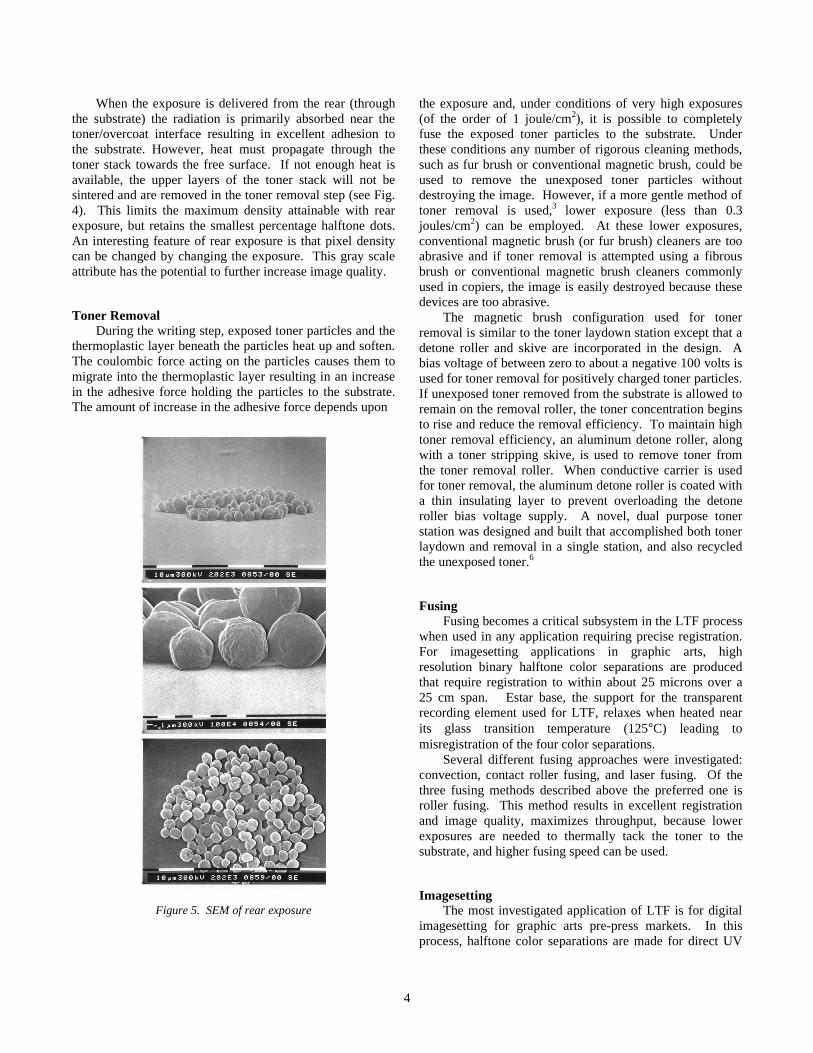
When the exposure is delivered from the rear (throughthe substrate) the radiation is primarily absorbed near thetoner/overcoat interface resulting in excellent adhesion tothe substrate. However, heat must propagate through thetoner stack towards the free surface. If not enough heat isavailable, the upper layers of the toner stack will not besintered and are removed in the toner removal step (see Fig.4). This limits the maximum density attainable with rearexposure, but retains the smallest percentage halftone dots.An interesting feature of rear exposure is that pixel densitycan be changed by changing the exposure. This gray scaleattribute has the potential to further increase image quality.
Toner RemovalDuring the writing step, exposed toner particles and the
thermoplastic layer beneath the particles heat up and soften.The coulombic force acting on the particles causes them tomigrate into the thermoplastic layer resulting in an increasein the adhesive force holding the particles to the substrate.The amount of increase in the adhesive force depends upon
Figure 5. SEM of rear exposure
the exposure and, under conditions of very high exposures(of the order of 1 joule/cm2), it is possible to completelyfuse the exposed toner particles to the substrate. Underthese conditions any number of rigorous cleaning methods,such as fur brush or conventional magnetic brush, could beused to remove the unexposed toner particles withoutdestroying the image. However, if a more gentle method oftoner removal is used,3 lower exposure (less than 0.3joules/cm2) can be employed. At these lower exposures,conventional magnetic brush (or fur brush) cleaners are tooabrasive and if toner removal is attempted using a fibrousbrush or conventional magnetic brush cleaners commonlyused in copiers, the image is easily destroyed because thesedevices are too abrasive.
The magnetic brush configuration used for tonerremoval is similar to the toner laydown station except that adetone roller and skive are incorporated in the design. Abias voltage of between zero to about a negative 100 volts isused for toner removal for positively charged toner particles.If unexposed toner removed from the substrate is allowed toremain on the removal roller, the toner concentration beginsto rise and reduce the removal efficiency. To maintain hightoner removal efficiency, an aluminum detone roller, alongwith a toner stripping skive, is used to remove toner fromthe toner removal roller. When conductive carrier is usedfor toner removal, the aluminum detone roller is coated witha thin insulating layer to prevent overloading the detoneroller bias voltage supply. A novel, dual purpose tonerstation was designed and built that accomplished both tonerlaydown and removal in a single station, and also recycledthe unexposed toner.6
FusingFusing becomes a critical subsystem in the LTF process
when used in any application requiring precise registration.For imagesetting applications in graphic arts, highresolution binary halftone color separations are producedthat require registration to within about 25 microns over a25 cm span. Estar base, the support for the transparentrecording element used for LTF, relaxes when heated nearits glass transition temperature (125°C) leading tomisregistration of the four color separations.
Several different fusing approaches were investigated:convection, contact roller fusing, and laser fusing. Of thethree fusing methods described above the preferred one isroller fusing. This method results in excellent registrationand image quality, maximizes throughput, because lowerexposures are needed to thermally tack the toner to thesubstrate, and higher fusing speed can be used.
ImagesettingThe most investigated application of LTF is for digital
imagesetting for graphic arts pre-press markets. In thisprocess, halftone color separations are made for direct UV

5
contact exposure of lithographic printing plates, or as anoptical mask for color proofing, or for contacting or dupingto silver film. Ultimately, multiple lithographic plates areexposed, processed, mounted, and registered in a press andused with their corresponding inks to rapidly create high-quality halftone color images on paper.
The LTF process was integrated with a modified KodakApproval™ digital color proofing system capable of 2540ppi resolution. Four-color 150 lpi halftone separations weremade from 8” x 10” digital graphic arts test images(Seybold targets: “musicians”). These separations were then“proofed” using Kodak Signature color proofing system,yielding high quality full color “press-like” images onpaper.
LTF provides some practical advantages whencompared to traditional silver based imagesetting systems.The process is dry and does not require or produce anysilver-containing liquids, or other materials that wouldrequire mandatory environmental management. Because ofits relative simplicity, the entire LTF process can beimplemented in a much more compact allotment ofequipment space. Also, unlike silver-based systems, theprocess is insensitive to any ambient room light. Finally,measurements have shown that the high contrast edgesharpness of dots and lines is comparable to the best silversystems. This is illustrated in Fig. 5 by a comparison ofedge sharpness for halftone dots made with LTF and dotsmade with a silver-based film. Figure 6 (a) and (b) shows a3-D plot in density space of midtone dots made using theLTF process and Kodak ImageLite HNF scanner film,respectively. The maximum density in both cases is about4.0 and edge density profiles are similar.
As stated earlier, the sensitivity of the LTF processdepends on several factors, including the choice of exposuredirection (front or rear), the solid area density requirements,and even the minimum halftone dot requirement, which, inturn, determines the laser spot size and pitch. With this inmind, the sensitivity of the process is roughly 250-350mJ/cm2 to produce 2-98% halftone dots at 150 lpi with amaximum density of 4.0 using front exposure.
Summary and Conclusions
This paper describes a new dry-writing process calledlaser-toner-fusion (LTF). The process is simple, robust, andis applicable to a number of graphic arts applications suchas imagesetting, color proofing, and computer-to-plateprinting. The process is capable of high quality (2540pixels per inch) imaging. The laser power requirements arebetween 100 mJ/cm2 to 300 mJ/cm2 depending on theapplication and required maximum density. These powerrequirements can be reduced through further development ofthe toners formulation development of the of the tonerformulation and recording substrate.
References
1. C. DeBoer, D. R. Kamp, and Mey, W., U. S. Patent #5,227,265.2. Kamp, D. R. and Mey, W., U. S. Patent #5,138,388.3. Miskinis, E. T. and Jadwin, T. A., U. S. Patent #4,546,060.4. Miskinis, E. T., Designing Materials For The Coloredge Copier
Program, SPSE, Sixth International Congress on advances inNon-Impact Printing Technologies, Orlando, FL (1990).
5. To avoid confusion, a magnetic brush development station isreferred to as a toner laydown station because, in this case ofLTF, it is used to apply a uniform toner layer and not to developa latent image.
6. Yousey, K. et al., U. S. Patent #5,229,825.
Figure 6. Measurement of edge sharpness of halftone dots
Biography
William Mey is a Research Fellow at Torrey PinesResearch currently working on printing technologies. Priorto joining Torrey Pines Research, he was a ResearchAssociate at Eastman Kodak Company working in the areaof non-impact printing technologies that includedelectrophotography, electrography, laser thermal, and inkjet.He has about 40 patents issued and has authored a number

6
of scientific publications. He received his Ph.D. in Physicsfrom Tulane University in 1973.
e-mail: [email protected]