Embed Size (px)
Citation preview
Laboratory-Scale High Temperature Electrolysis
System
Steve Herring Jim O’Brien, Carl Stoots, Grant Hawkes, Mike Mc Kellar, Manohar Sohal, Ed Harvego, Kevin DeWall, Doug Hall
Idaho National LaboratoryJoseph J. Hartvigsen, S. Elangovan, Dennis Larsen
Ceramatec, Inc.Mark Petri, Deborah Myers, Bilge Yildiz, David Carter, Richard Doctor
Argonne National LaboratoryBrian Bischoff [poster]
Oak Ridge National Laboratory
2006 DOE Hydrogen, Fuel Cells & Infrastructure Technologies Program Review Washington DC, May 17, 2006
PD17
This presentation does not contain any proprietary or confidential information
PD17 Herring 17May06 2
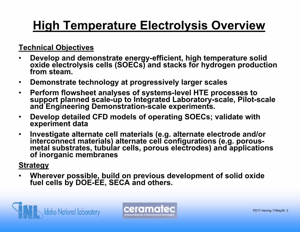
High Temperature Electrolysis OverviewTechnical Objectives • Develop and demonstrate energy-efficient, high temperature solid
oxide electrolysis cells (SOECs) and stacks for hydrogen production from steam.
• Demonstrate technology at progressively larger scales• Perform flowsheet analyses of systems-level HTE processes to
support planned scale-up to Integrated Laboratory-scale, Pilot-scale and Engineering Demonstration-scale experiments.
• Develop detailed CFD models of operating SOECs; validate with experiment data
• Investigate alternate cell materials (e.g. alternate electrode and/or interconnect materials) alternate cell configurations (e.g. porous-metal substrates, tubular cells, porous electrodes) and applications of inorganic membranes
Strategy• Wherever possible, build on previous development of solid oxide
fuel cells by DOE-EE, SECA and others.
PD17 Herring 17May06 3
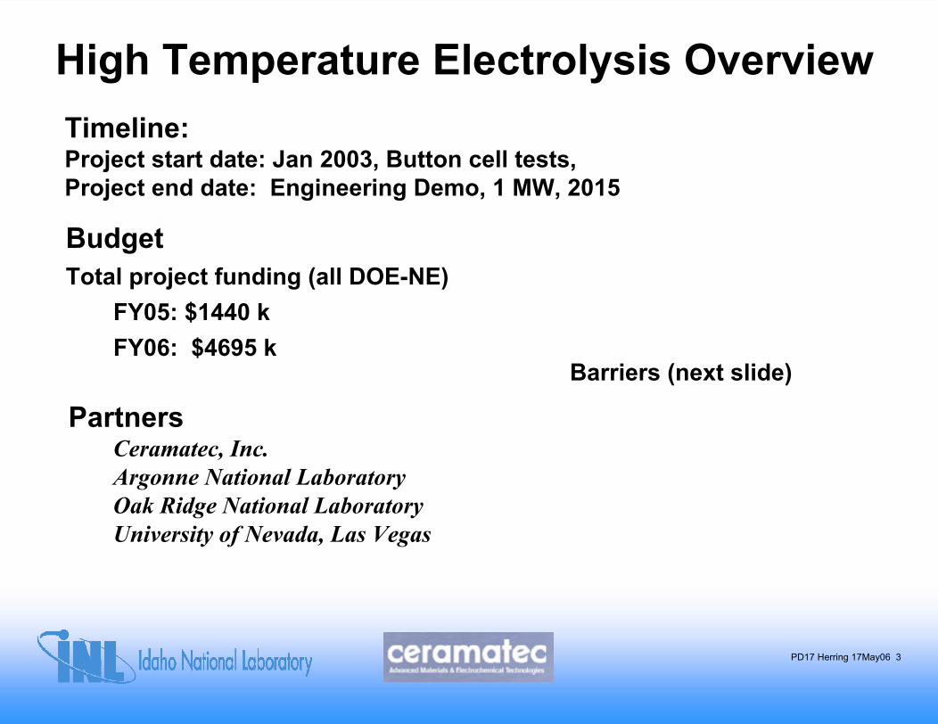
High Temperature Electrolysis OverviewTimeline:Project start date: Jan 2003, Button cell tests, Project end date: Engineering Demo, 1 MW, 2015
BudgetTotal project funding (all DOE-NE)
FY05: $1440 kFY06: $4695 k
Barriers (next slide)
PartnersCeramatec, Inc. Argonne National LaboratoryOak Ridge National LaboratoryUniversity of Nevada, Las Vegas
PD17 Herring 17May06 4
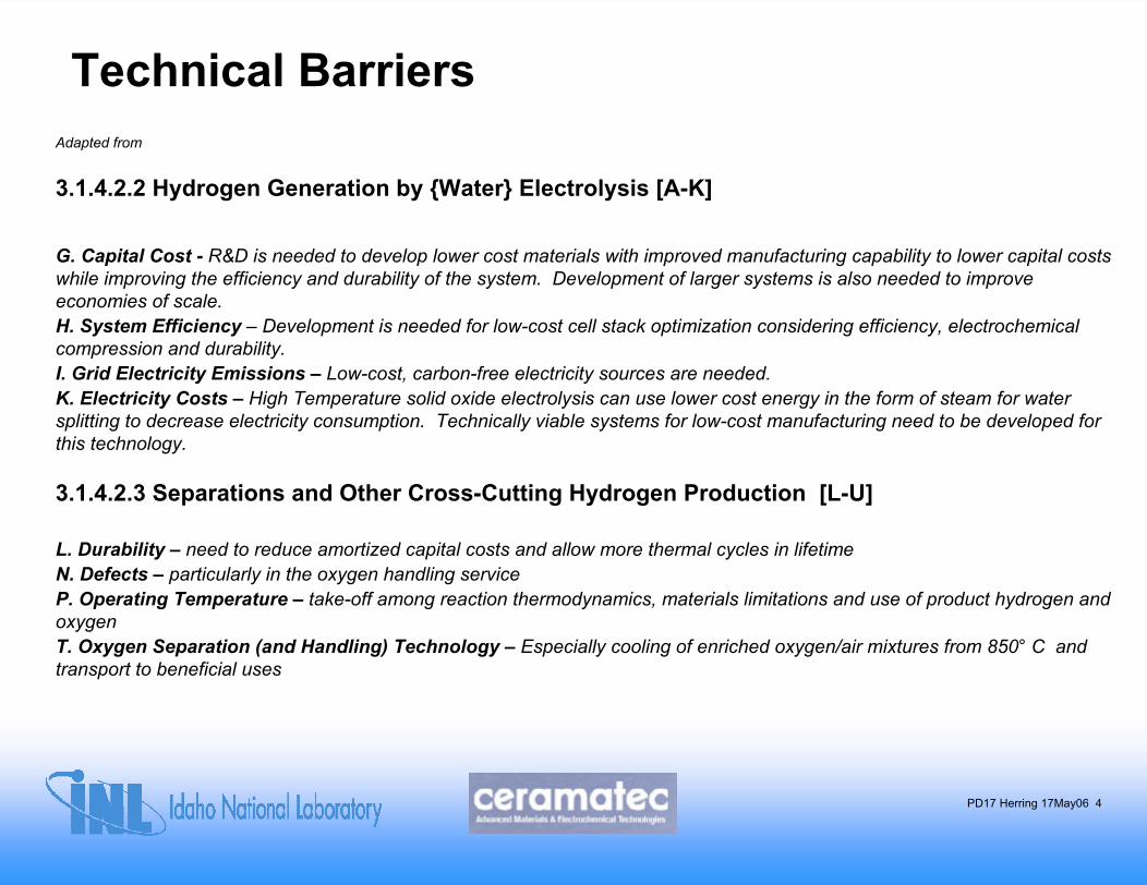
Technical BarriersAdapted from
3.1.4.2.2 Hydrogen Generation by Water Electrolysis [A-K]
G. Capital Cost - R&D is needed to develop lower cost materials with improved manufacturing capability to lower capital costs while improving the efficiency and durability of the system. Development of larger systems is also needed to improve economies of scale.H. System Efficiency – Development is needed for low-cost cell stack optimization considering efficiency, electrochemical compression and durability. I. Grid Electricity Emissions – Low-cost, carbon-free electricity sources are needed.K. Electricity Costs – High Temperature solid oxide electrolysis can use lower cost energy in the form of steam for water splitting to decrease electricity consumption. Technically viable systems for low-cost manufacturing need to be developed for this technology.
3.1.4.2.3 Separations and Other Cross-Cutting Hydrogen Production [L-U]
L. Durability – need to reduce amortized capital costs and allow more thermal cycles in lifetimeN. Defects – particularly in the oxygen handling serviceP. Operating Temperature – take-off among reaction thermodynamics, materials limitations and use of product hydrogen and oxygen T. Oxygen Separation (and Handling) Technology – Especially cooling of enriched oxygen/air mixtures from 850° C and transport to beneficial uses
PD17 Herring 17May06 5
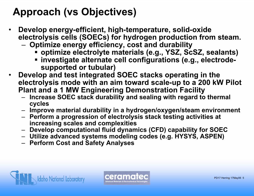
Approach (vs Objectives)• Develop energy-efficient, high-temperature, solid-oxide
electrolysis cells (SOECs) for hydrogen production from steam.– Optimize energy efficiency, cost and durability
optimize electrolyte materials (e.g., YSZ, ScSZ, sealants)investigate alternate cell configurations (e.g., electrode-supported or tubular)
• Develop and test integrated SOEC stacks operating in the electrolysis mode with an aim toward scale-up to a 200 kW Pilot Plant and a 1 MW Engineering Demonstration Facility– Increase SOEC stack durability and sealing with regard to thermal
cycles– Improve material durability in a hydrogen/oxygen/steam environment– Perform a progression of electrolysis stack testing activities at
increasing scales and complexities – Develop computational fluid dynamics (CFD) capability for SOEC– Utilize advanced systems modeling codes (e.g. HYSYS, ASPEN)– Perform Cost and Safety Analyses
PD17 Herring 17May06 6
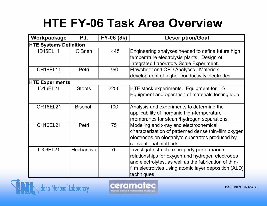
HTE FY-06 Task Area OverviewWorkpackage P.I. FY-06 ($k) Description/Goal
HTE Systems DefinitionID16EL11 O'Brien 1445 Engineering analyses needed to define future high
temperature electrolysis plants. Design of Integrated Laboratory Scale Experiment.
CH16EL11 Petri 750 Flowsheet and CFD Analyses. Materials development of higher conductivity electrodes.
HTE ExperimentsID16EL21 Stoots 2250 HTE stack experiments. Equipment for ILS.
Equipment and operation of materials testing loop.
OR16EL21 Bischoff 100 Analysis and experiments to determine the applicability of inorganic high-temperature membranes for steam/hydrogen separations.
CH16EL21 Petri 75 Modeling and x-ray and electrochemical characterization of patterned dense thin-film oxygen electrodes on electrolyte substrates produced by conventional methods.
ID06EL21 Hechanova 75 Investigate structure-property-performance relationships for oxygen and hydrogen electrodes and electrolytes, as well as the fabrication of thin-film electrolytes using atomic layer deposition (ALD) techniques.
PD17 Herring 17May06 7
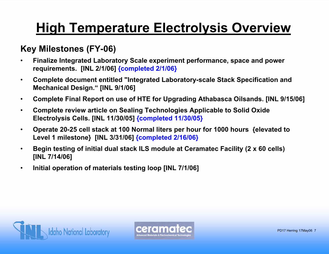
High Temperature Electrolysis OverviewKey Milestones (FY-06)• Finalize Integrated Laboratory Scale experiment performance, space and power
requirements. [INL 2/1/06] completed 2/1/06• Complete document entitled "Integrated Laboratory-scale Stack Specification and
Mechanical Design.“ [INL 9/1/06]• Complete Final Report on use of HTE for Upgrading Athabasca Oilsands. [INL 9/15/06] • Complete review article on Sealing Technologies Applicable to Solid Oxide
Electrolysis Cells. [INL 11/30/05] completed 11/30/05• Operate 20-25 cell stack at 100 Normal liters per hour for 1000 hours elevated to
Level 1 milestone [INL 3/31/06] completed 2/16/06• Begin testing of initial dual stack ILS module at Ceramatec Facility (2 x 60 cells)
[INL 7/14/06]• Initial operation of materials testing loop [INL 7/1/06]
PD17 Herring 17May06 8
High Temperature Electrolysis Overview
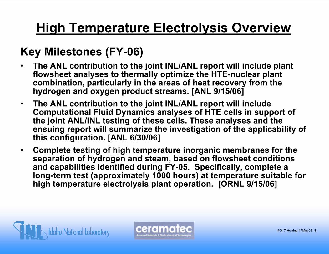
Key Milestones (FY-06)• The ANL contribution to the joint INL/ANL report will include plant
flowsheet analyses to thermally optimize the HTE-nuclear plant combination, particularly in the areas of heat recovery from thehydrogen and oxygen product streams. [ANL 9/15/06]
• The ANL contribution to the joint INL/ANL report will include Computational Fluid Dynamics analyses of HTE cells in support ofthe joint ANL/INL testing of these cells. These analyses and theensuing report will summarize the investigation of the applicability of this configuration. [ANL 6/30/06]
• Complete testing of high temperature inorganic membranes for theseparation of hydrogen and steam, based on flowsheet conditions and capabilities identified during FY-05. Specifically, complete a long-term test (approximately 1000 hours) at temperature suitable forhigh temperature electrolysis plant operation. [ORNL 9/15/06]
PD17 Herring 17May06 9
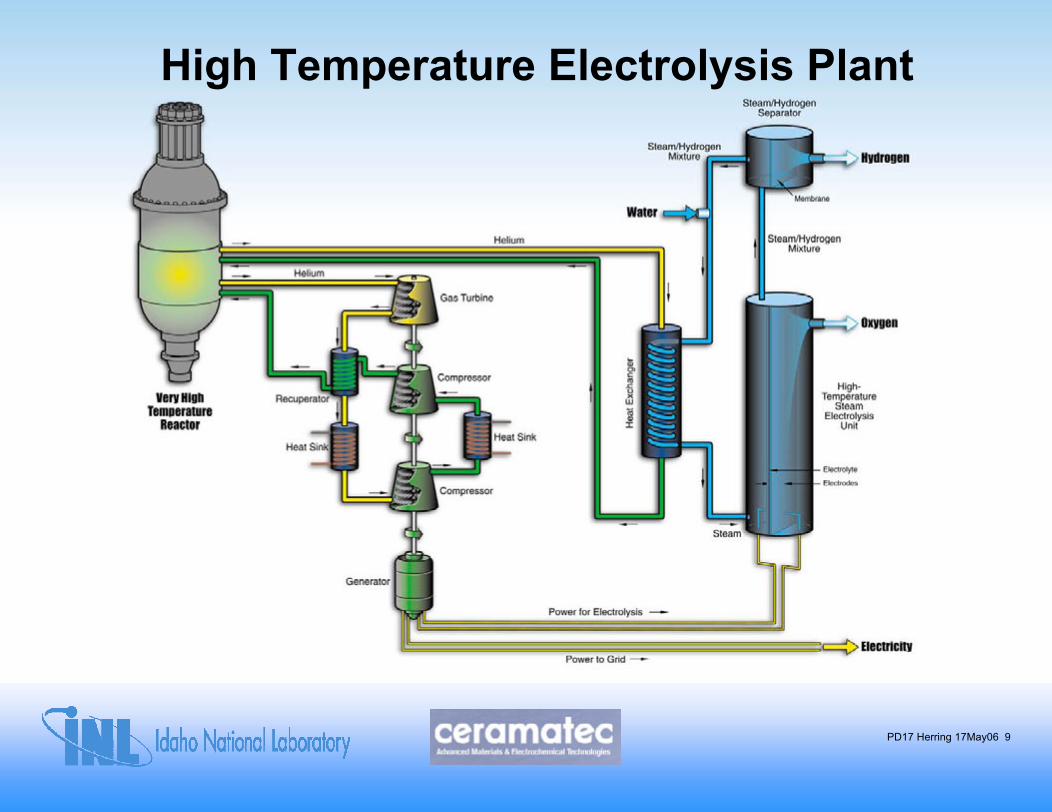
High Temperature Electrolysis Plant
PD17 Herring 17May06 10
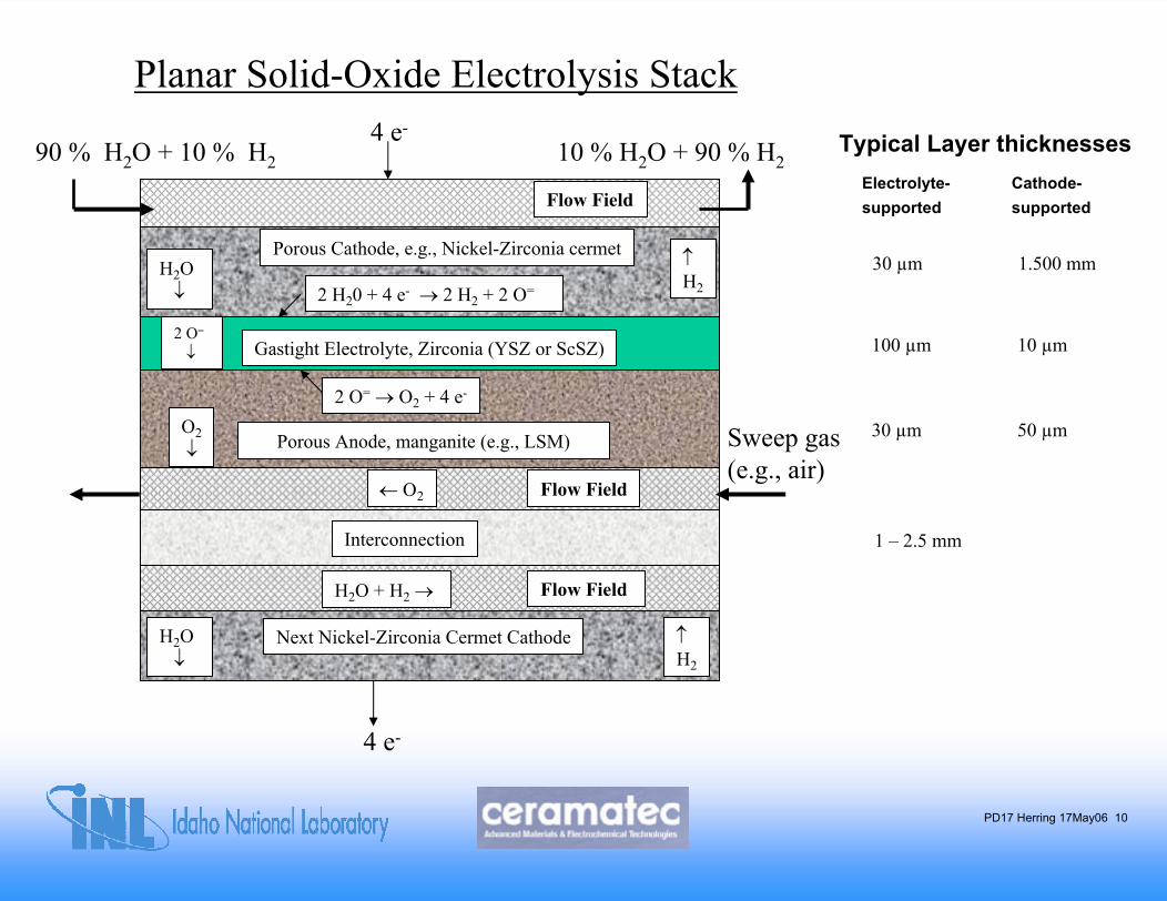
Planar Solid-Oxide Electrolysis Stack
Porous Anode, manganite (e.g., LSM)
Gastight Electrolyte, Zirconia (YSZ or ScSZ)
Porous Cathode, e.g., Nickel-Zirconia cermet
2 H20 + 4 e- → 2 H2 + 2 O=
2 O= → O2 + 4 e-
2 O=
↓
H2O↓
↑H2
O2↓
4 e-Typical Layer thicknesses90 % H2O + 10 % H2 10 % H2O + 90 % H2
Interconnection
H2O + H2 →
←Ο2
Next Nickel-Zirconia Cermet CathodeH2O↓
↑H2
Flow Field
Flow Field
4 e-
Flow FieldElectrolyte- Cathode-supported supported
30 µm 1.500 mm
100 µm 10 µm
30 µm 50 µmSweep gas (e.g., air)
1 – 2.5 mm
PD17 Herring 17May06 11
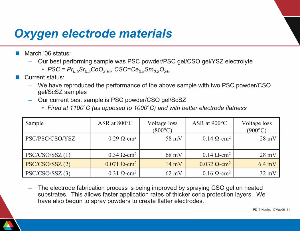
Oxygen electrode materialsMarch ‘06 status:
– Our best performing sample was PSC powder/PSC gel/CSO gel/YSZ electrolyte• PSC = Pr0.5Sr0.5CoO3 ±δ, CSO=Ce0.8Sm0.2O2±δ
Current status:– We have reproduced the performance of the above sample with two PSC powder/CSO
gel/ScSZ samples– Our current best sample is PSC powder/CSO gel/ScSZ
• Fired at 1100°C (as opposed to 1000°C) and with better electrode flatness
– The electrode fabrication process is being improved by spraying CSO gel on heated substrates. This allows faster application rates of thicker ceria protection layers. We have also begun to spray powders to create flatter electrodes.
Sample ASR at 800°C Voltage loss (800°C)
ASR at 900°C Voltage loss (900°C)
PSC/PSC/CSO/YSZ 0.29 Ω-cm2 58 mV
68 mV14 mV62 mV
0.14 Ω-cm2 28 mV
PSC/CSO/SSZ (1) 0.34 Ω-cm2 0.14 Ω-cm2 28 mVPSC/CSO/SSZ (2) 0.071 Ω-cm2 0.032 Ω-cm2 6.4 mVPSC/CSO/SSZ (3) 0.31 Ω-cm2 0.16 Ω-cm2 32 mV
PD17 Herring 17May06 12
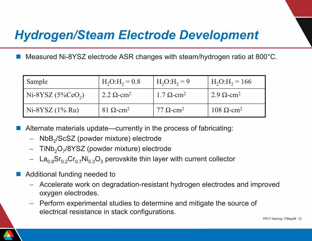
Hydrogen/Steam Electrode DevelopmentMeasured Ni-8YSZ electrode ASR changes with steam/hydrogen ratio at 800°C.
Alternate materials update—currently in the process of fabricating:– NbB2/ScSZ (powder mixture) electrode– TiNb2O7/8YSZ (powder mixture) electrode– La0.8Sr0.2Cr0.7Ni0.3O3 perovskite thin layer with current collector
Additional funding needed to– Accelerate work on degradation-resistant hydrogen electrodes and improved
oxygen electrodes.– Perform experimental studies to determine and mitigate the source of
electrical resistance in stack configurations.
Sample H2O:H2 = 0.8 H2O:H2 = 9 H2O:H2 = 166
Ni-8YSZ (5%CeO2) 2.2 Ω-cm2 1.7 Ω-cm2 2.9 Ω-cm2
Ni-8YSZ (1% Ru) 81 Ω-cm2 77 Ω-cm2 108 Ω-cm2
PD17 Herring 17May06 13
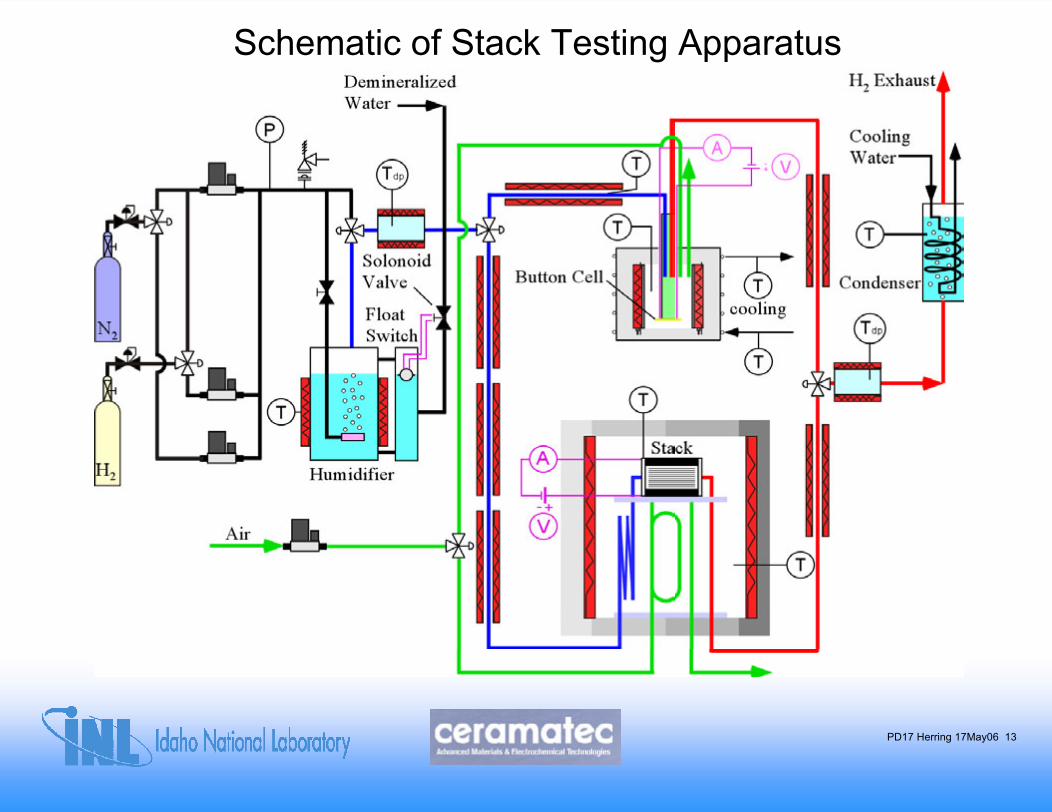
Schematic of Stack Testing Apparatus
PD17 Herring 17May06 14
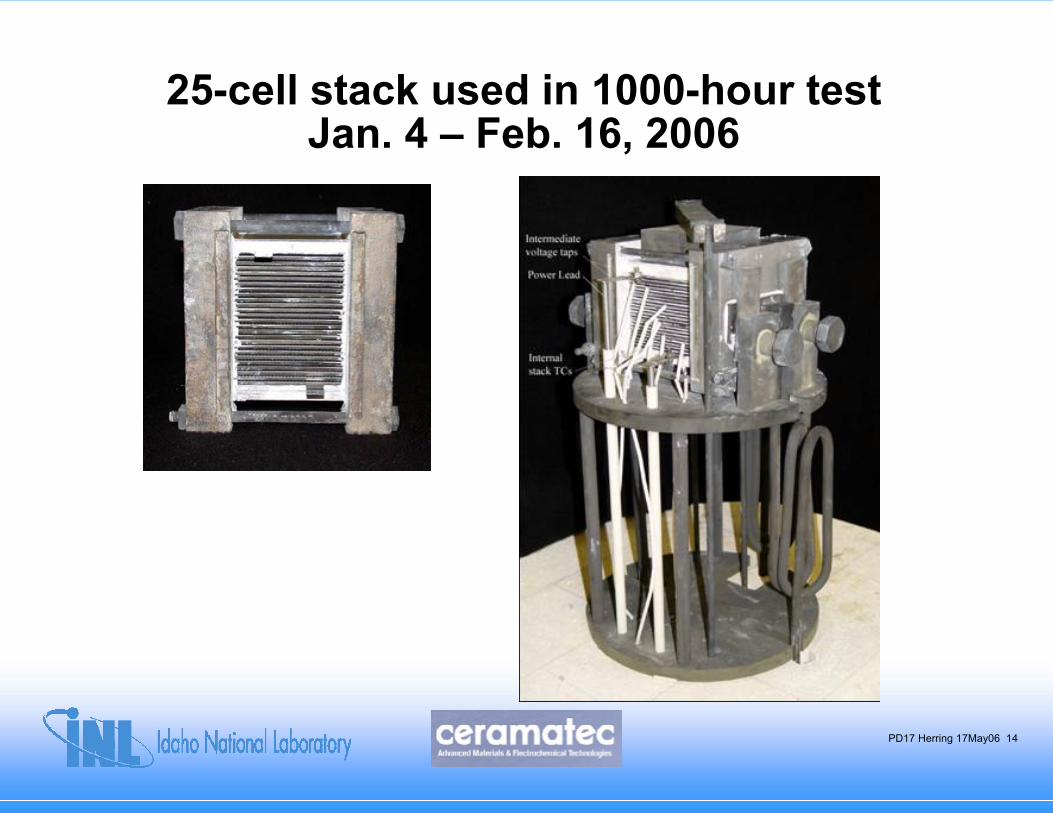
25-cell stack used in 1000-hour testJan. 4 – Feb. 16, 2006
PD17 Herring 17May06 15
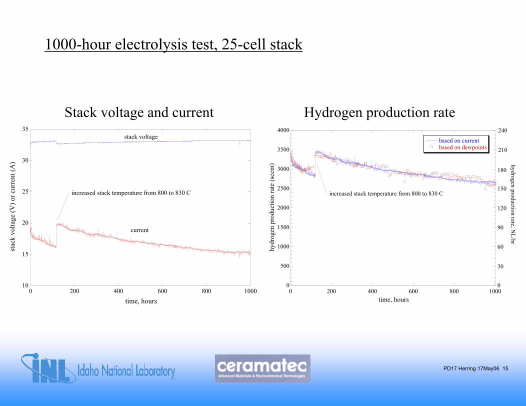
1000-hour electrolysis test, 25-cell stack
Stack voltage and current Hydrogen production rate
10
15
20
25
30
35
0 200 400 600 800 1000
stac
k vo
ltage
(V) o
r cur
rent
(A)
time, hours
stack voltage
current
increased stack temperature from 800 to 830 C
0
500
1000
1500
2000
2500
3000
3500
4000
0 200 400 600 800 1000
based on currentbased on dewpoints
hydr
ogen
pro
duct
ion
rate
(scc
m)
time, hours
increased stack temperature from 800 to 830 C
210
hydrogen production rate, NL/hr
180
150
120
90
60
30
0
240
PD17 Herring 17May06 16
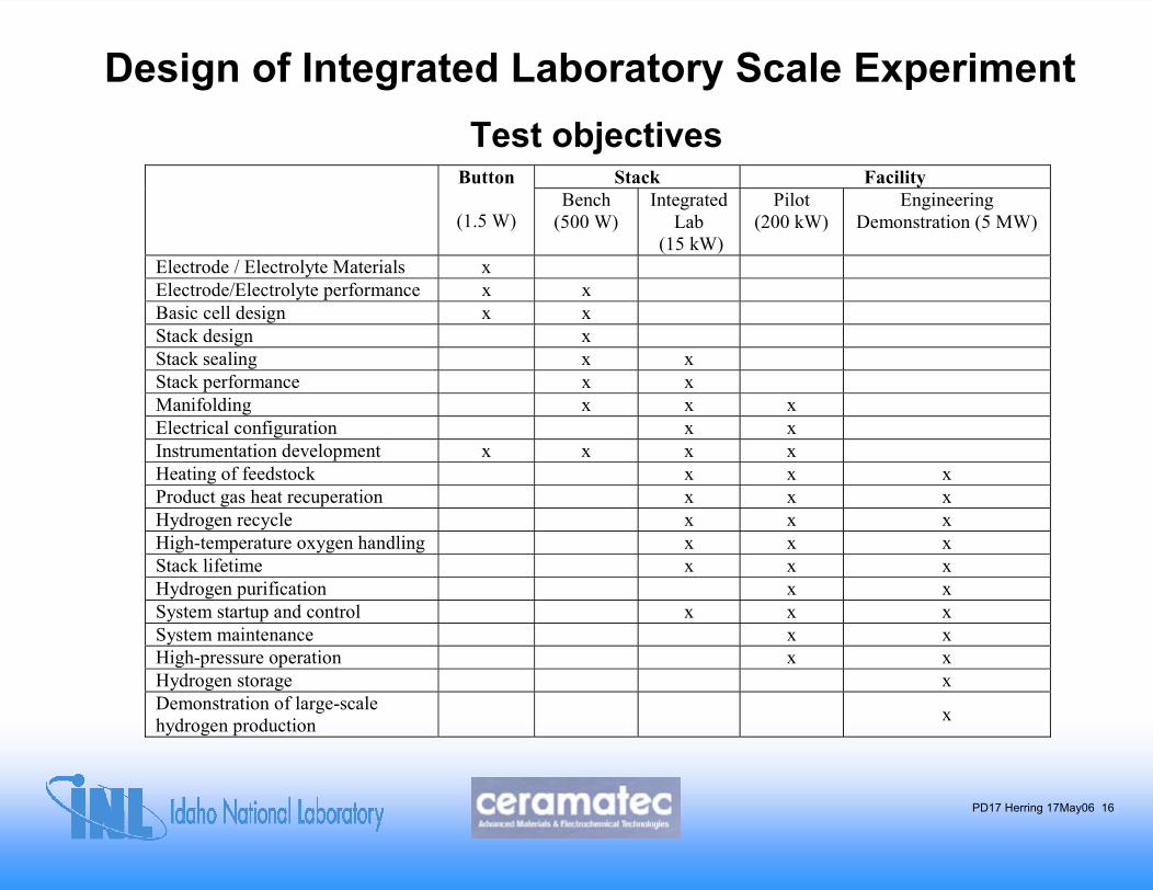
Design of Integrated Laboratory Scale ExperimentTest objectives
Stack Facility Button
(1.5 W) Bench
(500 W) Integrated
Lab (15 kW)
Pilot (200 kW)
Engineering Demonstration (5 MW)
Electrode / Electrolyte Materials x Electrode/Electrolyte performance x x Basic cell design x x Stack design x Stack sealing x x Stack performance x x Manifolding x x x Electrical configuration x x Instrumentation development x x x x Heating of feedstock x x x Product gas heat recuperation x x x Hydrogen recycle x x x High-temperature oxygen handling x x x Stack lifetime x x x Hydrogen purification x x System startup and control x x x System maintenance x x High-pressure operation x x Hydrogen storage x Demonstration of large-scale hydrogen production x
PD17 Herring 17May06 17
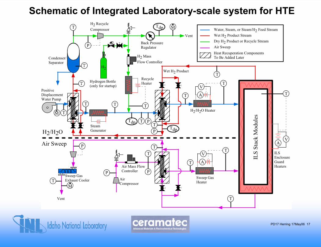
Schematic of Integrated Laboratory-scale system for HTE
T
H2
Air Mass FlowController
PositiveDisplacementWater Pump
Hydrogen Bottle(only for startup)
Condenser/Separator
H2/H2O Heater
H2 RecycleCompressor
Sweep GasExhaust Cooler
Water, Steam, or Steam/H2 Feed StreamWet H2 Product Stream
Air SweepDry H2 Product or Recycle Stream
Wet H2 Product
SteamGenerator
T
Sweep GasHeater
A
VT
ILS
Stac
kM
odul
es
Air Sweep
AirCompressor
Back PressureRegulatorP
Vent
Tdp M
T
Tdp T P
T
PTdp
T
RecycleHeater
TVent
T
H2 MassFlow Controller
T
T
T
T
T
H2/H2O
ILSEnclosureGuardHeaters
T
T
M
P P
M
VA
A
VT
Heat Recuperation ComponentsTo Be Added Later
P
PD17 Herring 17May06 18
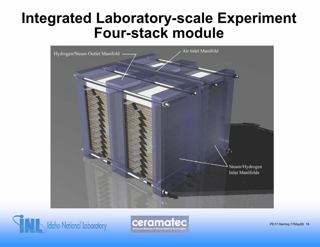
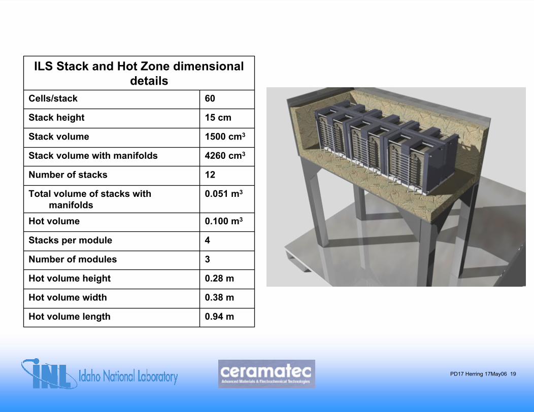
Integrated Laboratory-scale ExperimentFour-stack module
PD17 Herring 17May06 19
ILS Stack and Hot Zone dimensional details
Cells/stack 60
Stack height 15 cm
Stack volume 1500 cm3
Stack volume with manifolds 4260 cm3
Number of stacks 12
Total volume of stacks with manifolds
0.051 m3
Hot volume 0.100 m3
Stacks per module 4
Number of modules 3
Hot volume height 0.28 m
Hot volume width 0.38 m
Hot volume length 0.94 m
PD17 Herring 17May06 20
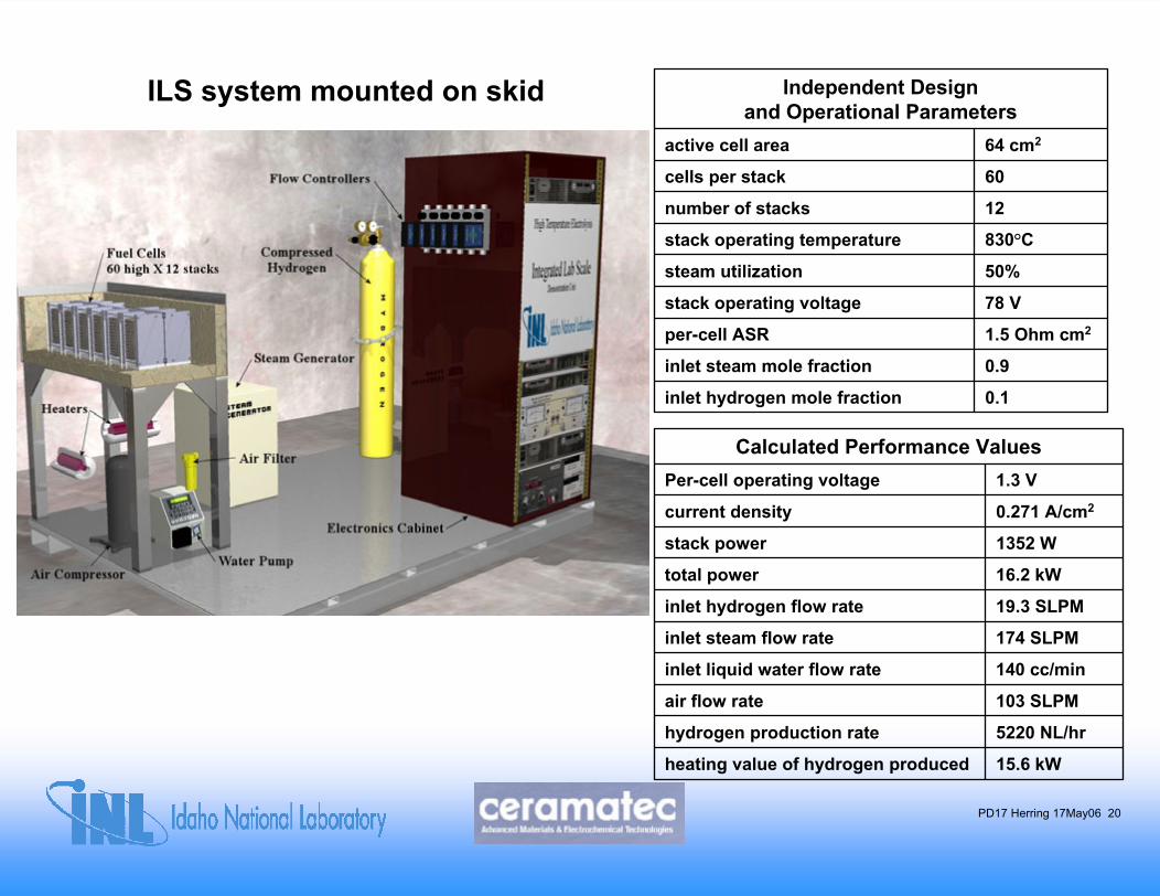
ILS system mounted on skid Independent Design and Operational Parameters
active cell area 64 cm2
cells per stack 60
number of stacks 12
stack operating temperature 830°C
steam utilization 50%
stack operating voltage 78 V
per-cell ASR 1.5 Ohm cm2
inlet steam mole fraction 0.9
inlet hydrogen mole fraction 0.1
Calculated Performance ValuesPer-cell operating voltage 1.3 V
current density 0.271 A/cm2
stack power 1352 W
total power 16.2 kW
inlet hydrogen flow rate 19.3 SLPM
inlet steam flow rate 174 SLPM
inlet liquid water flow rate 140 cc/min
air flow rate 103 SLPM
hydrogen production rate 5220 NL/hr
heating value of hydrogen produced 15.6 kW
PD17 Herring 17May06 21
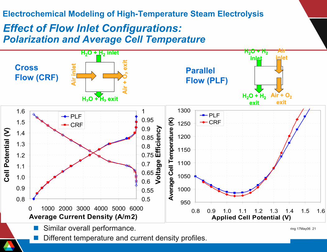
Electrochemical Modeling of High-Temperature Steam Electrolysis
Effect of Flow Inlet Configurations:Polarization and Average Cell Temperature
Similar overall performance.Different temperature and current density profiles.
0.8
0.9
1.0
1.1
1.2
1.3
1.4
1.5
1.6
0 1000 2000 3000 4000 5000 6000Average Current Density (A/m2)
Cel
l Pot
entia
l (V)
0.50.550.60.650.70.750.80.850.90.951
Volta
ge E
ffici
ency
PLFCRF
950
1000
1050
1100
1150
1200
1250
1300
0.8 0.9 1.0 1.1 1.2 1.3 1.4 1.5 1.6Applied Cell Potential (V)
Ave
rage
Cel
l Tem
pera
ture
(K) PLF
CRF
Cross Flow (CRF)
Parallel Flow (PLF)
H2O + H2inlet
Air + O2exit
H2O + H2exit
Air inlet
H2O + H2inlet
Air + O2exit
H2O + H2exit
Air inlet
H2O + H2 inlet
H2O + H2 exit
Air
+ O
2ex
it
Air
inle
t
H2O + H2 inlet
H2O + H2 exit
Air
+ O
2ex
it
Air
inle
t
PD17 Herring 17May06 22
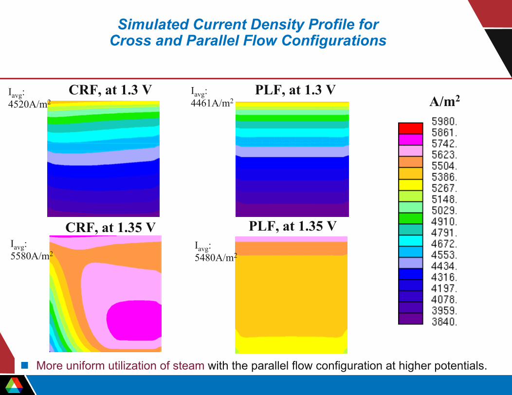
Simulated Current Density Profile for Cross and Parallel Flow Configurations
CRF, at 1.3 V PLF, at 1.3 VA/m2
More uniform utilization of steam with the parallel flow configuration at higher potentials.
PLF, at 1.35 VCRF, at 1.35 V
Iavg: 4520A/m2
Iavg: 5480A/m2
Iavg: 4461A/m2
Iavg: 5580A/m2
PD17 Herring 17May06 23
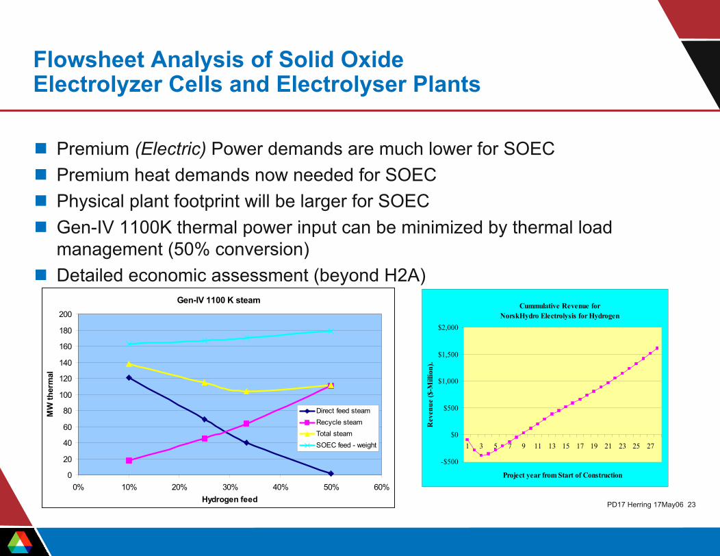
Flowsheet Analysis of Solid OxideElectrolyzer Cells and Electrolyser Plants
Premium (Electric) Power demands are much lower for SOECPremium heat demands now needed for SOEC Physical plant footprint will be larger for SOEC Gen-IV 1100K thermal power input can be minimized by thermal load management (50% conversion)Detailed economic assessment (beyond H2A)
Gen-IV 1100 K steam
0
20
40
60
80
100
120
140
160
180
200
0% 10% 20% 30% 40% 50% 60%Hydrogen feed
MW
ther
mal
Direct feed steamRecycle steamTotal steamSOEC feed - weight
Cummulative Revenue forNorskHydro Electrolysis for Hydrogen
-$500
$0
$500
$1,000
$1,500
$2,000
1 3 5 7 9 11 13 15 17 19 21 23 25 27
Project year from Start of Construction
Rev
enue
($-M
illio
n).
PD17 Herring 17May06 24
Response to 2005 Reviewers’ Comments:Comment: Wouldn’t a Mass Spec or GC measurement of hydrogen production be more direct than the dewpoint and electrical measurements?Response: In the past year we have occasionally used a gas chromatograph (Agilent 3000A Micro GC), but found that the results were less consistent than the dewpoint and electrical measurements.
Conclusions• Experimental results from a 25-cell stack, 64 cm2 active area, fabricated by Ceramatec:
– Hydrogen production rates in excess of 160 NL/hr were maintained with a 25-cell solid-oxide electrolysis stack for 1000 hours over the time period from January 5 to February 17, 2005.
– The stack endurance test was terminated due to completion of the milestone and not due to any problem with the stack itself.
– Stack performance as measured by the per-cell ASR was good, beginning at 1.60 ohm-cm2 and finishing at 2.15 ohm-cm2.
• The Integrated Laboratory Experiment will produce ~30x more hydrogen, while incorporating, at reduced scale, all of the components of a commercial plant.
• The collaboration between ANL and INL and in the development of electrodes and electrolytes has been very fruitful.
• INL, FLUENT and ANL developed electrochemical CFD models for electrolysis that predicts product flow, current density, temperature and ASR distributions within the SOEC.
• Thermal and electrochemical performance of SOECs can be greatly improved through design.
PD17 Herring 17May06 25
Publications• Herring, J. S., O’Brien, J. E., Stoots, C. M., and Hawkes, G. L., “Progress in High-Temperature Electrolysis for Hydrogen
Production using Planar SOFC Technology,” accepted for publication in the International Journal of Hydrogen Energy, 2006.• O’Brien, J. E., Stoots, C. M., Herring, J. S., and Hartvigsen, J. J.,“Hydrogen Production Performance of a 10-Cell Planar
Solid-Oxide Electrolysis Stack,” Journal of Fuel Cell Science and Technology, May, 2006.• Stoots, C. M., O’Brien, J. E., McKellar, M. G., Hawkes, G. L., and Herring, J. S., “Engineering Process Model for High-
Temperature Steam Electrolysis System Performance Evaluation,” AIChE 2005 Annual Meeting, Cincinnati, Oct. 30 – Nov. 4, 2005.
• Herring, J. S., O’Brien, J. E., Stoots, C. M., and Hawkes, G. L., “High Temperature Electrolysis for Hydrogen Production Using Nuclear Energy” Paper #501, GLOBAL 2005, Paper #501, Tsukuba, Japan, Oct. 9 – 13, 2005.
• O’Brien, J. E., Stoots, C. M., and Hawkes, G. L., “Comparison of a One-Dimensional Model of a High-Temperature Solid-OxideElectrolysis Stack with CFD and Experimental Results,” presented at the 2005 ASME International Mechanical Engineering Congress and Exposition, Nov. 5 – 11, Orlando.
• Hawkes, G. L., O’Brien, J. E., Stoots, C. M., Herring, J. S., Shahnam, M., “Thermal and Electrochemical Three Dimensional CFD Model of a Planar Solid Oxide Electrolysis Cell,” Proceedings, 2005 ASME Heat Transfer Conference, July 17-22, 2005, San Francisco.
• O’Brien, J. E., Stoots, C. M., Herring, J. S., Lessing, P. A., Hartvigsen, J. J., and Elangovan, S., “Performance Measurements of Solid-Oxide Electrolysis Cells for Hydrogen Production from Nuclear Energy,” Journal of Fuel Cell Science and Technology, Vol. 2, August 2005, pp. 156-163.
• Herring, J. S., O’Brien, J. E., Stoots, C. M., and Hawkes, G. L., “Progress in High-Temperature Electrolysis for Hydrogen Production using Planar SOFC Technology,” 2005 AIChE Spring Annual Meeting, April 10 – 14, 2005, Atlanta, GA.
• O’Brien, J. E., Stoots, C. M., Herring, J. S., and Hartvigsen, J. J.,“Hydrogen Production Performance of a 10-Cell Planar Solid-Oxide Electrolysis Stack,” Proceedings, ASME 3rd International Conference on Fuel Cell Science, Engineering, and Technology, May 23 – 25, 2005, Ypsilanti, MI.
• Hawkes, G. L., O’Brien, J. E., Stoots, C. M., Herring, J. S., Shahnam, M., “CFD Model of a Planar Solid Oxide Electrolysis Cell for Hydrogen Production from Nuclear Energy,” to be presented at the 11th International Topical Meeting on Nuclear Reactor Thermal-Hydraulics NURETH-11, Popes Palace Conference Center, Avignon, France, October 2-6, 2005.
• O’Brien, J. E., Herring, J. S., Stoots, C. M., Lessing, P. A., “High-Temperature Electrolysis for Hydrogen Production From Nuclear Energy,” to be presented at the 11th International Topical Meeting on Nuclear Reactor Thermal-Hydraulics NURETH-11, Popes Palace Conference Center, Avignon, France, October 2-6, 2005.