Embed Size (px)
Citation preview
Format No.: DCE/Stud/LM/34/Issue:00/Revision:01 1
DHANALAKSHMI COLLEGE OF ENGINEERING
Manimangalam, Tambaram, Chennai – 601 301
DEPARTMENT OF
MECHANICAL ENGINEERING
EE 8361- Electrical Engineering LABORATORY
III SEMESTER - R 2017
LABORATORY MANUAL
Name :
Register No. :
Class :
Format No.: DCE/Stud/LM/34/Issue:00/Revision:01 2
DHANALAKSHMI COLLEGE OF ENGINEERING
VISION
Dhanalakshmi College of Engineering is committed to provide highly disciplined, conscientious and enterprising
professionals conforming to global standards through value based quality education and training.
MISSION
To provide competent technical manpower capable of meeting requirements of the industry
To contribute to the promotion of Academic Excellence in pursuit of Technical Education at different levels
To train the students to sell his brawn and brain to the highest bidder but to never put a price tag on heart and soul
DEPARTMENT OF ELECTRICAL AND ELECTRONICS ENGINEERING
VISION
To strive for acquiring, applying and imparting knowledge in Electrical and Electronics Engineering through quality
education and to provide enthusiastic professionals with commitment
MISSION
To educate the students with the state-of-art technologies to meet the growing challenges of the electronics industry
To carry out research through continuous interaction with research institutes and industry, on advances in
communication systems
To provide the students with strong ground rules to facilitate them for systematic learning, innovation and ethical
practices

Format No.: DCE/Stud/LM/34/Issue:00/Revision:01 3
PROGRAMME EDUCATIONAL OBJECTIVES (PEOs)
1. Fundamentals
To impart students with fundamental knowledge in Mathematics, Science and fundamentals of Engineering that will
would them to be successful professionals
2. Core Competence
To provide students with sound knowledge in engineering and experimental skills to identify complex software
problems in industry and to develop practical solution for them
3. Breadth
To provide relevant training and experience to bridge the gap between theory and practice this enables to find
solutions for real time problem in industry and organization and to design products requiring interdisciplinary skills
4. Professionalism skills
To bestow students with adequate training and provide opportunities to work as team that will build up their
communication skills, individual leadership and supportive qualities and to develop them to adapt and work in ever
changing technologies
5. Lifelong Learning
To develop the ability of students to establish themselves as professionals in Electrical and Electronics Engineering
and to create awareness about the need for lifelong learning and pursuing advanced degrees

Format No.: DCE/Stud/LM/34/Issue:00/Revision:01 4
PROGRAMME OUTCOMES (POs)
a) To demonstrate and apply knowledge of Mathematics, Science and engineering fundamentals in Electrical
and Electronics Engineering field
b) To design a component, a system or a process to meet the specific needs within the realistic constraints
such as economics, environment, ethics, health, safety and manufacturability
c) To demonstrate the competency to use software tools for computation, simulation and testing of electrical and
electronics engineering circuits
d) To identify, formulate and solve electrical and electronics engineering problems
e) To demonstrate an ability to visualize and work on laboratory and multidisciplinary tasks
f) To function as a member or a leader in multidisciplinary activities
g) To communicate in verbal and written form with fellow engineers and society at large
h) To understand the impact of Electrical and Electronics Engineering in the society and demonstrate awareness
of contemporary issues and commitment to give solutions exhibiting social responsibility
i) To demonstrate professional & ethical responsibilities
j) To exhibit confidence in self-education and ability for lifelong learning
k) To participate and succeed in competitive exams
Format No.: DCE/Stud/LM/34/Issue:00/Revision:01 5
EE6365 – Electrical Engineering Laboratory
SYLLABUS
COURSE OBJECTIVES
To validate the principles studied in theory by performing experiments in the laboratory
LIST OF EXPERIMENTS
1. Load test on DC Shunt & DC Series motor
2. O.C.C & Load characteristics of DC Shunt and DC Series generator
3. Speed control of DC shunt motor (Armature, Field control)
4. Load test on single phase transformer
5. O.C & S.C Test on a single phase transformer
6. Regulation of an alternator by EMF & MMF methods.
7. V curves and inverted V curves of synchronous Motor
8. Load test on three phase squirrel cage Induction motor
9. Speed control of three phase slip ring Induction Motor
10. Load test on single phase Induction Motor.
11. Study of DC & AC Starters
COURSE OUTCOMES
1. Ability to perform the load test on DC shunt and DC series motor
2. Ability to understand the O.C.C & Load characteristics of DC Shunt and DC Series generator
3. Ability to control the speed of DC shunt motor
4. Ability to perform the load test on single phase transformer
5. To perform the open circuit and short circuit test on a single phase transformer
6. Ability to perform the open circuit test and short circuit test on a single-phase transformer and to calculate the efficiency and regulation
7. Ability to perform the OC and SC tests on a given 3-Φ alternator and also to calculate the regulation by (i) EMF method (ii) MMF method
8. Ability to perform the V and inverted V curves for the given three phase synchronous motor
9. Ability to perform the direct load test on a given 3-phase induction motor and to understand the performance characteristics of the machine
10. Ability to perform the speed control test on the three-phase slip ring induction motor by rotor resistance control
11. Ability to perform the load test on a single phase induction motor
12. Ability to study the different types of DC and AC starters
Sl. No. Name o f the experiment Page no.
1. Load test on DC shunt motor
2. Load test on DC Series motor
3. O.C.C & Load characteristics of DC Shunt generator
4. Load characteristics of DC Series generator
5 Speed control of DC shunt motor (Armature, Field control)
6 Load test on single phase transformer
7 O.C & S.C Test on a single phase transformer
8 Regulation of an alternator by EMF & MMF methods
9 Load test on three phase squirrel cage Induction motor
10 Load test on single phase squirrel cage Induction motor
11 Speed control of three phase slip ring Induction Motor
12 V curves and inverted V curves of synchronous Motor
13 Study of AC and DC motor starters
6 Format No.: DCE/Stud/LM/34/Issue:00/Revision:01
Format No.: DCE/Stud/LM/34/Issue:00/Revision:01 7
Aim: To obtain the performance characteristics of the given D.C. shunt motor by conducting load test.
Apparatus required:
SL. No. Name of the equipment Range & Type Quantity
1 Voltmeter (0-300 V), MC 1 No
2 Ammeter (0-20 A), MC 1 No
3 Rheostat 220 Ω, 2 A 1No
4 Tachometer, (0 – 10000 rpm) 1each
Theory:
The performance of DC shunt motor such as Torque, Efficiency and speed with respect to output power
can be determined by conducting an actual test. This type of test is conducted on small capa city machines
normally in the laboratories to study the behavior of the motor for different load conditions. The frictional load is
introduced and the speed decreases and back emf reduces which will increase the current taken by the motor
from the supply. Likewise for different frictional loads the motor parameters such as speed, torque and efficiency
are studied.
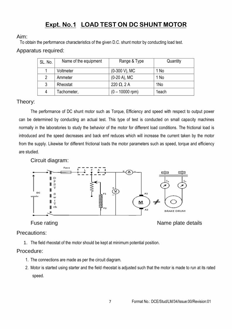
Circuit diagram:
Fuse rating Name plate details
Precautions:
1. The field rheostat of the motor should be kept at minimum potential position.
Procedure:
1. The connections are made as per the circuit diagram.
2. Motor is started using starter and the field rheostat is adjusted such that the motor is made to run at its rated
speed.
Expt. No.1 LOAD TEST ON DC SHUNT MOTOR
Format No.: DCE/Stud/LM/34/Issue:00/Revision:01 8
3. Note down the reading of Ammeter, Voltmeter and spring balance. Theses readings are called as no load
readings.
4. Adjust the spring balances, thereby a friction is introduced between the belt and brake drum now the motor is
loaded, note down the corresponding speed, spring balance, Ammeter and Voltmeter readings.
5. Repeat the above step for different current till Ammeter reads the rated current of the motor. For the different
currents note down speed, spring balance and voltmeter readings.
6. Remove the loads by reducing the friction between brake drum and belt.
7. Bring the field rheostat to the minimum resistance position and switch off the supply by opening DPST
switch.
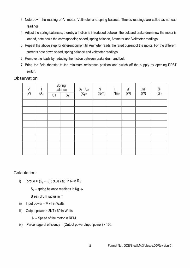
Observation:
V (V)
I (A)
Spring balance
S1 ~ S2
(Kg)
N (rpm)
T (Nm)
I/P (W)
O/P (W)
%(%)
S1 S2
Calculation:
i) Torque = (S1 ~ S2 ) 9.81 (R) in N-M S1,
S2 – spring balance readings in Kg R-
Break drum radius in m
ii) Input power = V x I in Watts
iii) Output power = 2NT / 60 in Watts
N – Speed of the motor in RPM
iv) Percentage of efficiency = (Output power /Input power) x 100.
Format No.: DCE/Stud/LM/34/Issue:00/Revision:01 9
Spe
ed (N
) in
rpm
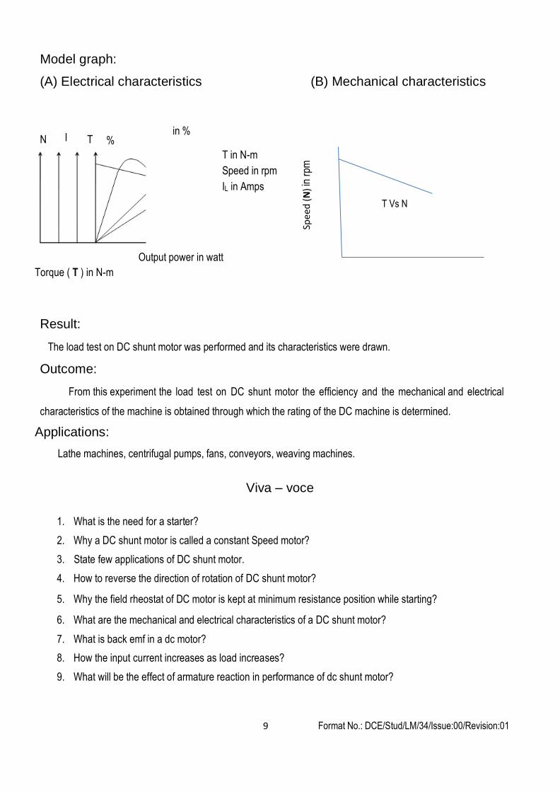
Model graph:
(A) Electrical characteristics (B) Mechanical characteristics
N I T % in %
T in N-m
Speed in rpm
IL in Amps
T Vs N
Output power in watt
Torque ( T ) in N-m
Result:
The load test on DC shunt motor was performed and its characteristics were drawn.
Outcome:
From this experiment the load test on DC shunt motor the efficiency and the mechanical and electrical
characteristics of the machine is obtained through which the rating of the DC machine is determined.
Applications:
Lathe machines, centrifugal pumps, fans, conveyors, weaving machines.
Viva – voce
1. What is the need for a starter?
2. Why a DC shunt motor is called a constant Speed motor?
3. State few applications of DC shunt motor.
4. How to reverse the direction of rotation of DC shunt motor?
5. Why the field rheostat of DC motor is kept at minimum resistance position while starting?
6. What are the mechanical and electrical characteristics of a DC shunt motor?
7. What is back emf in a dc motor?
8. How the input current increases as load increases?
9. What will be the effect of armature reaction in performance of dc shunt motor?
Format No.: DCE/Stud/LM/34/Issue:00/Revision:01 10
Aim:
Expt. No. 2 LOAD TEST ON DC SERIES MOTOR
To obtain the performance characteristics of a DC series motor by conducting load test.
Apparatus required:
SL. No. Name of the equipment Range & Type Quantity
1 Voltmeter (0-300 V), MC 1 No.
2 Ammeter (0-20 A), MC 1 No.
3 Tachometer - 1 No
Theory:
The performance of DC series motor such as Torque, Efficiency and speed with respect to output power
can be determined by conducting an actual test. This type of test is conducted on small capacity machines
normally in the laboratories to study the behavior of the motor for different load conditions. The DC series motor
should not be started on no load like other DC motor. Here the field winding is connected in series with armature.
If the motor is started on no load the current flowing through the field coil will be minimum in turn the flux is
minimum. This will increase the speed to abnormal value since the speed and flux are inversely proportional in DC
motors. So the DC series motors are started with some load (usually frictional load). As frictional load is introduced
and the speed decreases and back emf reduces which will increase the current taken by the motor from th e
supply. Likewise for different frictional loads the motor parameters such as speed, torque and efficiency are
studied.
Circuit diagram:
Fuse rating Name plate details Precautions 1. Before starting the motor the load is applied on the brake drum with the help of spring balance.
Format No.: DCE/Stud/LM/34/Issue:00/Revision:01 11
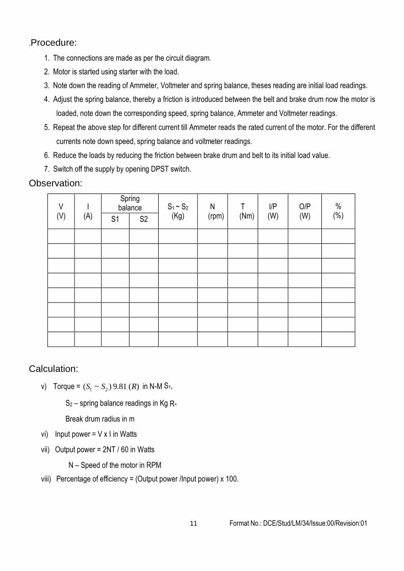
.Procedure:
1. The connections are made as per the circuit diagram.
2. Motor is started using starter with the load.
3. Note down the reading of Ammeter, Voltmeter and spring balance, theses reading are initial load readings.
4. Adjust the spring balance, thereby a friction is introduced between the belt and brake drum now the motor is
loaded, note down the corresponding speed, spring balance, Ammeter and Voltmeter readings.
5. Repeat the above step for different current till Ammeter reads the rated current of the motor. For the different
currents note down speed, spring balance and voltmeter readings.
6. Reduce the loads by reducing the friction between brake drum and belt to its initial load value.
7. Switch off the supply by opening DPST switch.
Observation:
V (V)
I (A)
Spring balance
S1 ~ S2
(Kg)
N (rpm)
T (Nm)
I/P (W)
O/P (W)
%(%) S1 S2
Calculation:
v) Torque = (S1 ~ S2 ) 9.81 (R) in N-M S1,
S2 – spring balance readings in Kg R-
Break drum radius in m
vi) Input power = V x I in Watts
vii) Output power = 2NT / 60 in Watts
N – Speed of the motor in RPM
viii) Percentage of efficiency = (Output power /Input power) x 100.

Format No.: DCE/Stud/LM/34/Issue:00/Revision:01 12
Result:
The load test on DC series motor was performed and its characteristics were drawn.
Outcome:
From this experiment the load test on DC series motor, the efficiency and the mechanical and electrical
characteristics of the machine is obtained through which the rating of the DC machine is determined.
Applications:
Hoist, cranes, Trolley cars, pumps, blowers.
Viva – voce
1. Why a DC series motor should not be stared without load?
2. Why a DC series motor has a high starting torque?
3. Compare the resistances of the field windings of DC shunt and series motor?
4. What are the applications of DC series motor?
5. Comment on the Speed – Torque characteristics of a DC series motor.
6. What is the precaution to be taken when working with a D.C series motor?
7. What is the need for starter with a D.C motor?
8. How does a 2-point starter function?
9. Explain the shape of the electrical and mechanical characteristics.
10. What is the condition for maximum efficiency in a D.C motor?
11. What are the different losses occurring in a D.C machine?
12. How are the meter ratings selected for this experiment?
13. Give some applications of D.C series motor
Format No.: DCE/Stud/LM/34/Issue:00/Revision:01 13
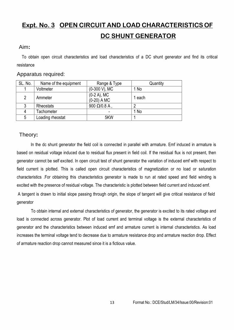
Expt. No. 3 OPEN CIRCUIT AND LOAD CHARACTERISTICS OF
DC SHUNT GENERATOR
Aim:
To obtain open circuit characteristics and load characteristics of a DC shunt generator and find its critical
resistance
Apparatus required:
SL. No. Name of the equipment Range & Type Quantity
1 Voltmeter (0-300 V), MC 1 No
2
Ammeter (0-2 A), MC (0-20) A MC
1 each
3 Rheostats 900 Ω/0.8 A , 2
4 Tachometer - 1 No
5 Loading rheostat 5KW 1
Theory:
In the dc shunt generator the field coil is connected in parallel with armature. Emf induced in armature is
based on residual voltage induced due to residual flux present in field coil. If the residual flux is not present, then
generator cannot be self excited. In open circuit test of shunt generator the variation of induced emf with respect to
field current is plotted. This is called open circuit characteristics of magnetization or no load or sa turation
characteristics .For obtaining this characteristics generator is made to run at rated speed and field winding is
excited with the presence of residual voltage. The characteristic is plotted between field current and induced emf.
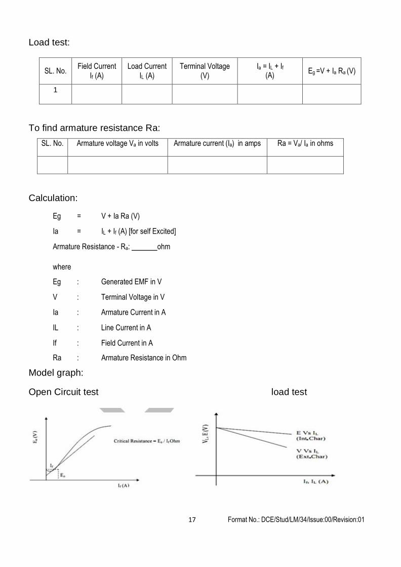
A tangent is drawn to initial slope passing through origin, the slope of tangent will give critical resistance of field
generator
To obtain internal and external characteristics of generator, the generator is excited to its rated voltage and
load is connected across generator. Plot of load current and terminal voltage is the external characteristics of
generator and the characteristics between induced emf and armature current is internal characteristics. As load
increases the terminal voltage tend to decrease due to armature resistance drop and armature reaction drop. Effect
of armature reaction drop cannot measured since it is a fictious value.
Format No.: DCE/Stud/LM/34/Issue:00/Revision:01 14
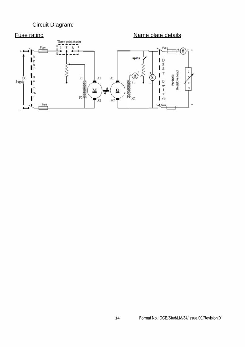
Circuit Diagram:
Fuse rating Name plate details
Format No.: DCE/Stud/LM/34/Issue:00/Revision:01 15
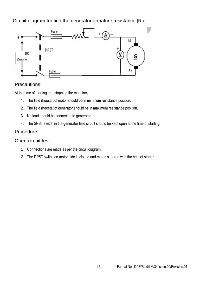
Circuit diagram for find the generator armature resistance [Ra]
Precautions:
At the time of starting and stopping the machine,
1. The field rheostat of motor should be in minimum resistance position.
2. The field rheostat of generator should be in maximum resistance position.
3. No load should be connected to generator.
4. The SPST switch in the generator field circuit should be kept open at the time of starting
Procedure:
Open circuit test:
1. Connections are made as per the circuit diagram.
2. The DPST switch on motor side is closed and motor is stared with the help of starter
Format No.: DCE/Stud/LM/34/Issue:00/Revision:01 16
3. By adjusting the motor field rheostat, the generator is brought to rated speed.
4. The voltage induced due to residual flux is noted in the voltmeter connected across the armature circuit.The
SPST switch in field circuit is closed.
5. By varying the generator field rheostat, the excitation and induced emf are measured ammeter and voltmeter
6. Generator field rheostat is adjusted till maximum voltage indicated in voltmeter and corresponding ammeter
readings are noted
7. Generator field rheostat is brought to maximum resistance position
Load test:
8. By adjusting field rheostat of generator till armature induced emf reaches its rated voltage.
9. The DPST switch on generator load side is closed
10. The load is varied in steps, for each step the load current, field current, terminal voltage is noted. For each
step ensure the speed of generator at its rated value
11. Vary the load till ammeter reds the rated current of generator
12. After noting down meter readings the load on generator is removed and DPST switch on generator side is
open
13. Generator field rheostat is brought to maximum resistance position and motor field rheostat field is brought to
minimum resistance position and DPST switch o motor circuit is open.
To find armature resistance Ra:
1. Check loading rheostat must be at maximum resistance position.
2. Close the DPST switch and vary the loading rheostat for various values in steps and noted the corresponding
voltmeter and ammeter reading.
3. Open the DPST switch after loading rheostat begins its initial position.
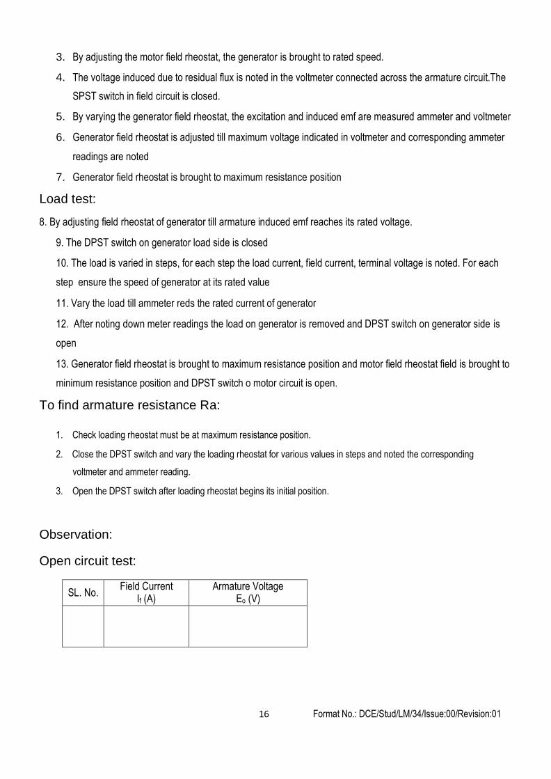
Observation:
Open circuit test:
SL. No. Field Current
If (A)
Armature Voltage Eo (V)
Format No.: DCE/Stud/LM/34/Issue:00/Revision:01 17
Load test:
SL. No.
Field Current If (A)
Load Current IL (A)
Terminal Voltage (V)
Ia = IL + If (A)
Eg =V + Ia Ra (V)
1
To find armature resistance Ra:
SL. No. Armature voltage Va in volts Armature current (Ia) in amps Ra = Va/ Ia in ohms
Calculation:
Eg = V + Ia Ra (V)
Ia = IL + If (A) [for self Excited]
Armature Resistance - Ra: ohm
where
Eg : Generated EMF in V
V : Terminal Voltage in V
Ia : Armature Current in A
IL : Line Current in A
If : Field Current in A
Ra : Armature Resistance in Ohm
Model graph:
Open Circuit test load test

Format No.: DCE/Stud/LM/34/Issue:00/Revision:01 18
Result:
Thus the open circuit characteristics and load characteristics of a self-excited DC shunt generator were
plotted and its critical resistance was obtained.
Outcome:
From this experiment the open circuit characteristics and load characteristics of a DC shunt generator with its critical resistance was determined through which the point at which the generator would build up voltage can be found.
Applications:
General lighting, battery chargers, source of excitation to alternators, power supply units
Viva – voce
1. How can you find the residual voltage of the generator?
2. State Faradays’ law of electromagnetic induction and interaction.
3. What is the difference you can see experimentally between self excited and separately excited?
4. If any other prime mover can be used in this experiment?
5. What is a magnetization characteristic of DC generator?
6. What is meant by critical resistance of a generator?
7. What is meant by critical speed?
8. Why in a DC machine, the armature core should be laminated?
9. What are the applications of DC shunt generator?
10. What will be the no load emf, when the no load speed changes to 1000 rpm?
11. What happen if the field current of the DC motor varies during load test?
12. What are the factors which represent the nature of external characteristics in DC shunt generator?
13. When load increases there is fall in generated voltage why?
14. What is the effect of armature reaction on external and internal characteristics of DC shunt generator?
Format No.: DCE/Stud/LM/34/Issue:00/Revision:01 19
Aim:
Expt. No.4 LOAD CHARACTERISTICS OF DC SERIES
GENERATOR
To obtain internal and external characteristics of a given DC series generator by conducting load test.
Apparatus required:
SL. No. Name of the equipment Range & Type Quantity
1 Voltmeter (0-300 V), MC 1 No
2 Ammeter (0-20) A MC 1 each
3 Rheostats 900 Ω/0.83 A, 1 each
4 Loading rheostat 5KW 1
5 Tachometer - 1 No
Theory:
The Dc series generator consists of field coil that will produce necessary flux to induce voltage in the
armature similar to that of dc shunt generator with a difference , field coil is connected in series with armature. The dc
series generator a residual flux is required to built the voltage generated in armature.
With the help of residual voltage, when the load is connected across generator will drive a current through the field
coil. This in term will increase the flux and also voltage induced. By keeping varying the load the current flowing
through field coil increased and hence thermal voltage. the current passing through armature ,series field and load
are one and the same and it can be called as load current or armature current. The characteristics so obtained by
varying load terminal voltage increases with load current and this characteristics is called as external characteristics
(Terminal voltage vs load current)
Internal characteristics obtained by determining by induced emf for each loads (E=V+Ia *(Ra+Rse)). A tangent is drawn for initial slope of external characteristics passing through origin. The slope of the tangent will give critical low resistance for dc series generator.
Precautions:
Load test:
1. The field rheostat in motor circuit should be at minimum resistance position.
2. The Generator side DPST switch should be open at time starting.
Procedure:
1. Connections are given as shown in the circuit diagram.
2. The DPST switch on motor side is closed and motor is started with help of starter
3. The field rheostat with motor circuit is adjusted till the generator runs at rated speed
4. The DPST switch on generator side is closed and the load is switched ON in steps.
Format No.: DCE/Stud/LM/34/Issue:00/Revision:01 20
5. For each step of load variation the ammeter and voltmeter readings are noted keeping generator at its rated
speed
6. The load is varied till the ammeter reads rated current of generator
7. Remove all the loads and open the DPST switch on generator side. Bring the field rheostat to minimum
resistance position and open DPST switch.
8. Measure the armature and series field resistances
Observation:
Load Test
S. No.
Load Current IL= Ia = If (A)
Terminal Voltage Vt (V)
E=V+Ia *(Ra+Rse) (V)
Calculation:
Eg = V + Ia Ra (V)
Ia = IL + If (A) [for self Excited]
Armature Resistance - Ra: Ω
where
Eg : Generated EMF in V
V : Terminal Voltage in V
Ia : Armature Current in A
IL : Line Current in A
If : Field Current in A
Ra : Armature Resistance in Ohm
Result:
The extertnal characteristics and internal characteristics were drawn and critical load resistance is obtained.
Outcome:
From this experiment the open circuit characteristics and load characteristics of a DC series generator with its critical resistance was determined through which the point at which the generator would build up voltage can be found.
Applications:
Used for 1. Supplying field excitation current in DC locomotives 2. Boosters to compensate the voltage drop in the feeders 3. In series arc lightening

Format No.: DCE/Stud/LM/34/Issue:00/Revision:01 21
Viva - voce
1. Why external characteristics having increase in load voltage as a load increases?
2. What is the significance of critical load resistance?
3. If the residual flux is zero, how to excite generator?
4. How to obtain the open circuit characteristics of generator
5. What will be the effect of armature effect in generator?
Format No.: DCE/Stud/LM/34/Issue:00/Revision:01 22
Aim:
Expt. No.5 SPEED CONTROL OF DC SHUNT MOTOR
To obtain speed control characteristics of the given D.C. shunt motor by armature and field control methods
Apparatus required:
SL. No. Apparatus Range & Type Quantity
1 Voltmeter (0-300 V) MC 1 No
2 Ammeter (0-1 A) MC, (0-5 A) MC 1 each
3 Rheostats (220 Ω/2 A), (900 Ω/0.8 A) 1 each
4 Tachometer - 1 No
Theory:
In a DC motor the speed is directly proportional to back emf and inversely proportional to flux. In order to
study the variation of speed by keeping either back emf or the flux is maintained constant. By keeping the back emf
constant and varying the flux is called flux or field control. Similarly keeping the flux constant and varying the back
emf is called armature control.
To study the speed control characteristics ,a dc shunt motor is preferred because dc series motor and dc
compound motors are normally considered under load condition. Since the speed control test is conducted on no
load for study purpose.The drop due to armature resistance will be very small,hence back emf is approximately equal
to applied voltage.
In the armature control method field current is maintained constant and voltage applied to armature vary and
the corresponding variation in speed is observed. For different values of field current a set of armature control
characteristics is obtained.
In the field control method armature voltage is maintained constant and for various values of field current ,the
speed is observed. For different values of armature voltage a set of field control characteristics is obtained
Precautions: (not to be included in the record)
1. The rheostat connected in series with armature should be kept in maximum resistance position
2. The rheostat connected in series with field should be kept in minimum resistance position
Procedure:
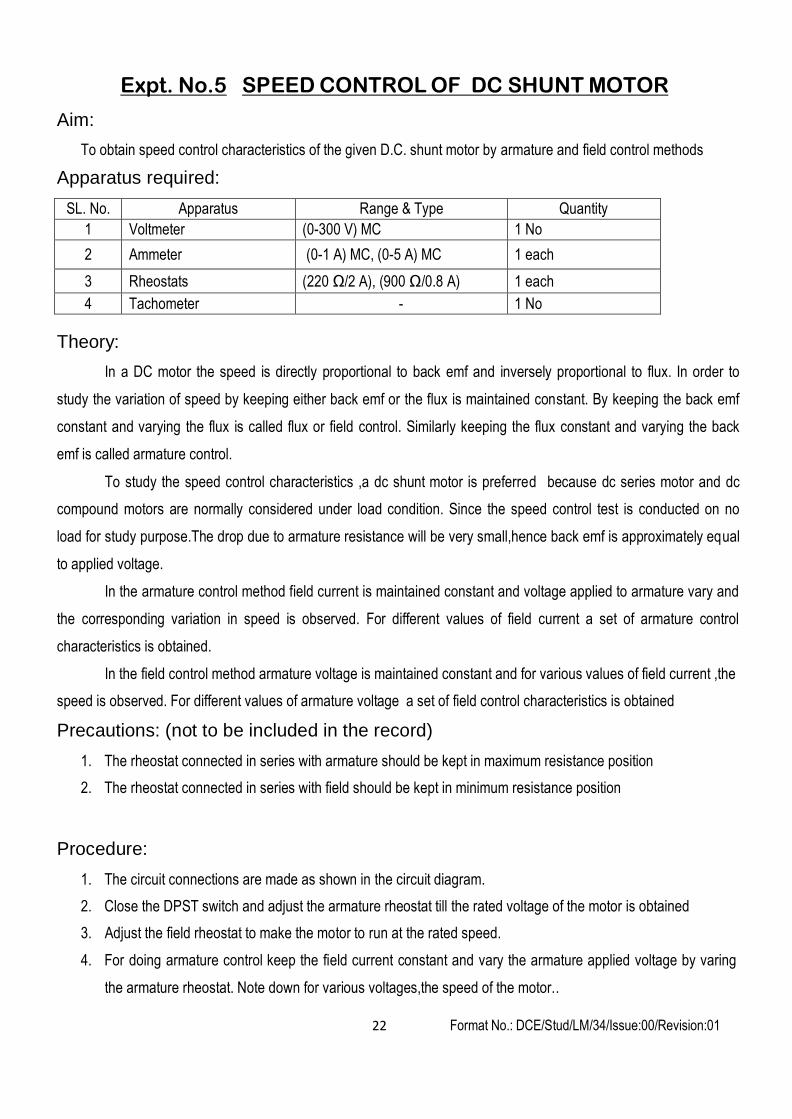
1. The circuit connections are made as shown in the circuit diagram.
2. Close the DPST switch and adjust the armature rheostat till the rated voltage of the motor is obtained
3. Adjust the field rheostat to make the motor to run at the rated speed.
4. For doing armature control keep the field current constant and vary the armature applied voltage by varing
the armature rheostat. Note down for various voltages,the speed of the motor..
Format No.: DCE/Stud/LM/34/Issue:00/Revision:01 23
S.no Va
(V) N
(rpm)
5. The above step is repeated for different value of field current and the corresponding voltage and speed is
obtained.
6. Keeping armature voltage at its rated value, vary the field rheostat. For various field current note down the
speed of motor
7. The above step is repeated for different value of armature voltage and the corresponding field current and
speed is obtained.
8. After the above steps keep the armature rheostat in maximum resistance position and field rheostat in
minimum resistance position, open dpst switch
Circuit diagram:
Fuse Rating
Observation:
Name Plate Details
Field Control Method
Armature voltage=
v
Armature Control Method
Field Current= A
S.no If (A)
N (rpm)
Format No.: DCE/Stud/LM/34/Issue:00/Revision:01 24
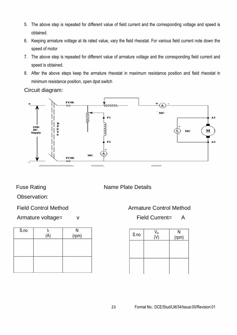
Model graph:
Result:
The Armature and field speed control characteristics were drawn for various various field current and
armature voltage.
Outcome:
From this experiment, the D.C shunt motor characteristics are studied by Armature – controlled and Field
control methods through which the motor can be made to run at the desired speed and starting current can also be
reduced.
Applications:
Constant speed applications- Automotive applications (winding/unwinding machines) ,Lathes, Centrifugal
pumps, Belt driven applications.
Viva – voce
1. The test conducted for speed control in laboratory for what load and why?
2. In armature control the variation of speed below the rated speed explain
3. Why speed is increasing in field control method?
4. What will be type of characteristics possible using armature control when the motor is loaded
5.What will be type of characteristics possible using field control when the motor is loaded
Format No.: DCE/Stud/LM/34/Issue:00/Revision:01 25
Expt No.6 LOAD TEST ON A SINGLE PHASE TRANSFORMER
Aim:
To determine efficiency and regulation characteristics of a single phase transformer by conducting load test
Apparatus required:
SL. No.
Apparatus
Range & Type
Quantity
1
Single Phase Transformer
230/115 V
1 No
2
Voltmeter AC (0-150 V), MI (0-300 V), MI
1each
3
Ammeter AC (0-10 A), MI (0-5 A), MI
1each
4
Wattmeter (20A,150 V, UPF) (10A,300 V, UPF)
1each
5
Resistive load
5KW
1 No
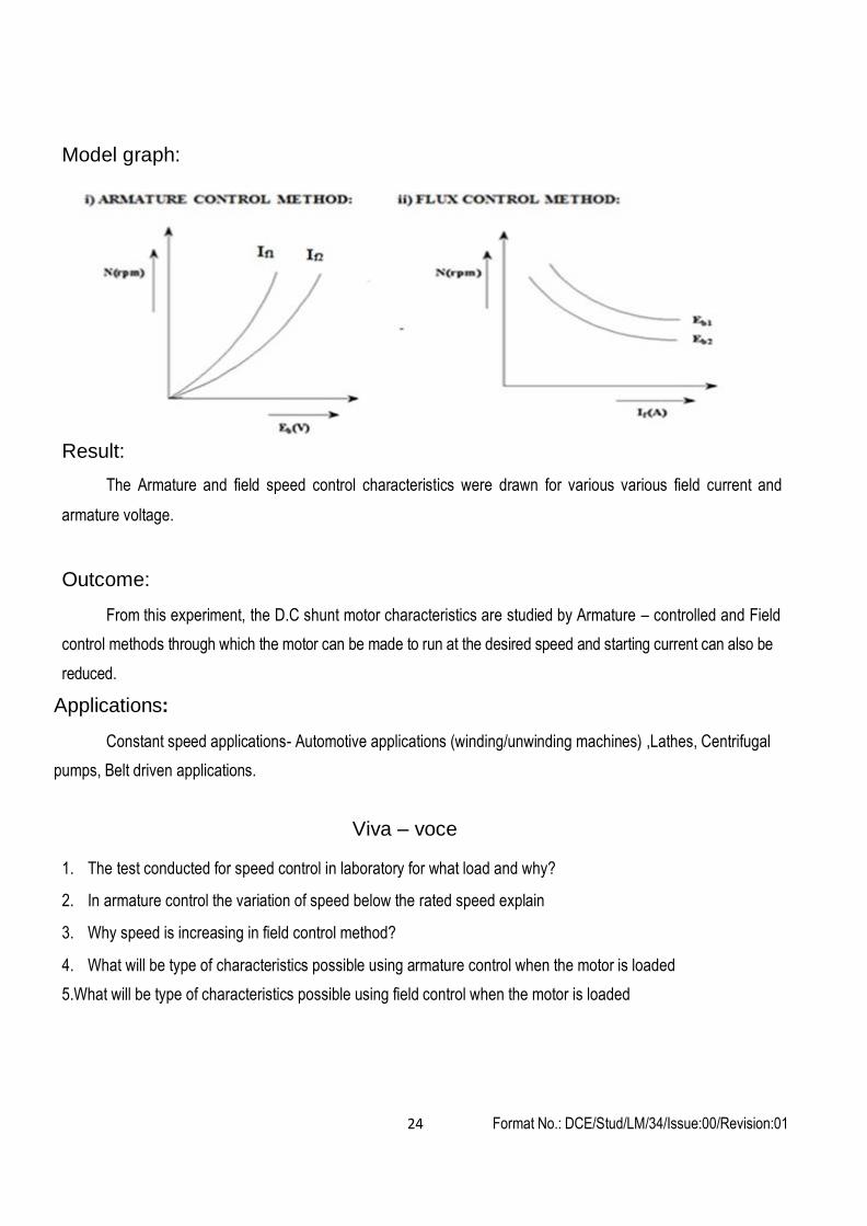
Circuit diagram:
Format No.: DCE/Stud/LM/34/Issue:00/Revision:01 26
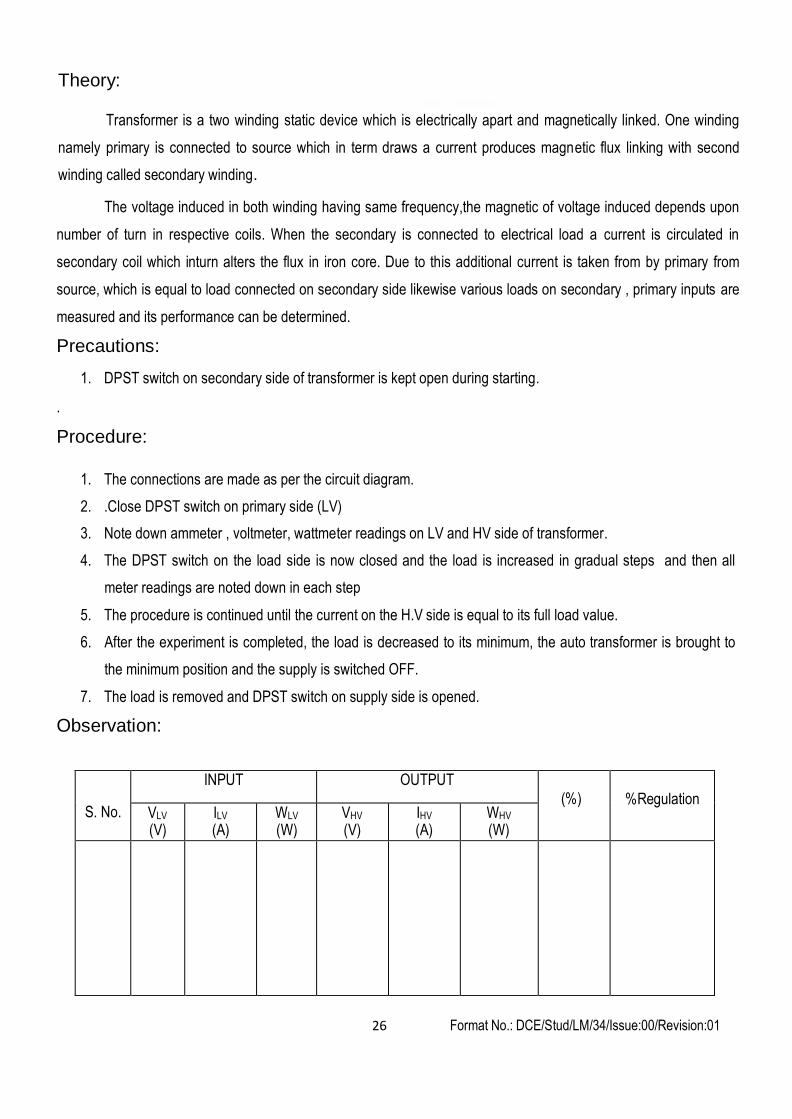
Theory:
Transformer is a two winding static device which is electrically apart and magnetically linked. One winding
namely primary is connected to source which in term draws a current produces magnetic flux linking with second
winding called secondary winding.
The voltage induced in both winding having same frequency,the magnetic of voltage induced depends upon
number of turn in respective coils. When the secondary is connected to electrical load a current is circulated in
secondary coil which inturn alters the flux in iron core. Due to this additional current is taken from by primary from
source, which is equal to load connected on secondary side likewise various loads on secondary , primary inputs are
measured and its performance can be determined.
Precautions:
1. DPST switch on secondary side of transformer is kept open during starting.
.
Procedure:
1. The connections are made as per the circuit diagram.
2. .Close DPST switch on primary side (LV)
3. Note down ammeter , voltmeter, wattmeter readings on LV and HV side of transformer.
4. The DPST switch on the load side is now closed and the load is increased in gradual steps and then all
meter readings are noted down in each step
5. The procedure is continued until the current on the H.V side is equal to its full load value.
6. After the experiment is completed, the load is decreased to its minimum, the auto transformer is brought to
the minimum position and the supply is switched OFF.
7. The load is removed and DPST switch on supply side is opened.
Observation:
S. No.
INPUT OUTPUT (%)
%Regulation
VLV
(V) ILV
(A) WLV
(W) VHV
(V) IHV
(A) WHV
(W)

Format No.: DCE/Stud/LM/34/Issue:00/Revision:01 27
Calculations:
1. The Output Power of the transformer = VH.V * IH.V on the H.V side
2. The Input Power of the transformer = WL.V = Wattmeter reading on the L.V side
3. % Efficiency (%η) = (OUTPUT / INPUT) * 100
Format No.: DCE/Stud/LM/34/Issue:00/Revision:01 28
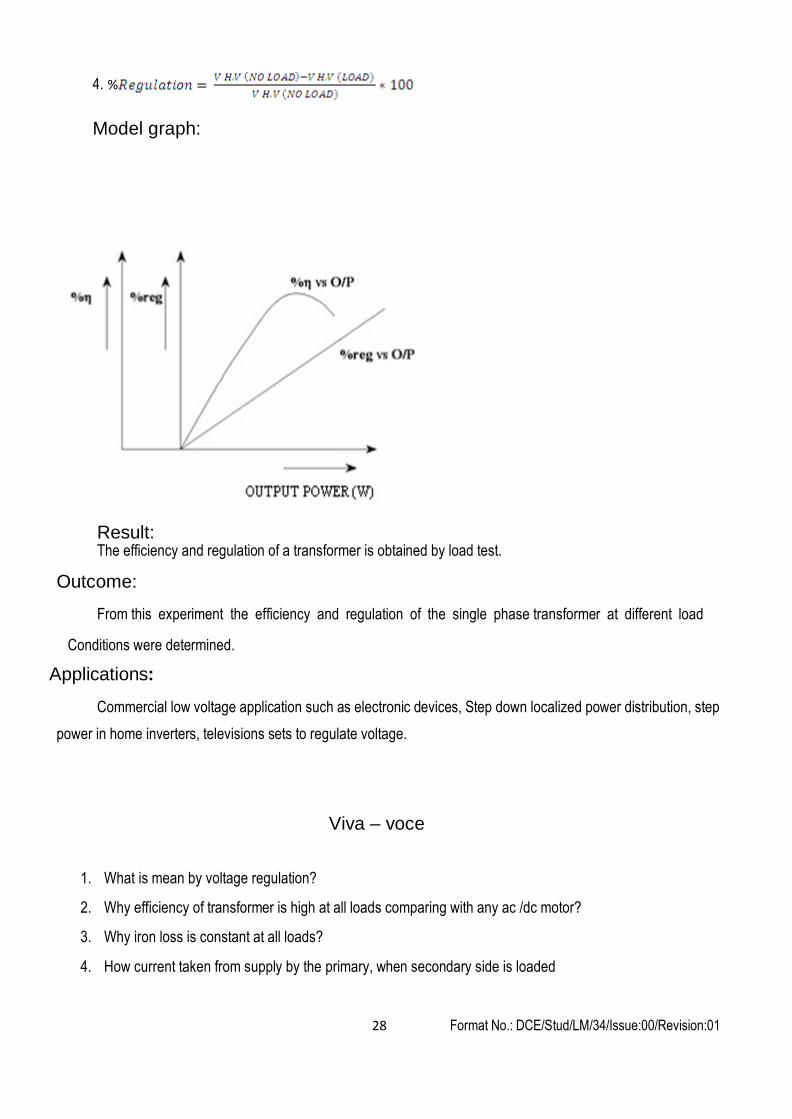
4. %
Model graph:
Result: The efficiency and regulation of a transformer is obtained by load test.
Outcome:
From this experiment the efficiency and regulation of the single phase transformer at different load
Conditions were determined.
Applications:
Commercial low voltage application such as electronic devices, Step down localized power distribution, step
power in home inverters, televisions sets to regulate voltage.
Viva – voce
1. What is mean by voltage regulation?
2. Why efficiency of transformer is high at all loads comparing with any ac /dc motor?
3. Why iron loss is constant at all loads?
4. How current taken from supply by the primary, when secondary side is loaded
Format No.: DCE/Stud/LM/34/Issue:00/Revision:01 29
Expt. No. 7 OPEN CIRCUIT AND SHORT CIRCUIT TESTS ON A
SINGLE PHASE TRANSFORMER
Aim:
To determine equivalent circuit parameters of a single phase transformer by conducting open circuit test and short
circuit test also predetermine the efficiency and regulation characteristics..
Apparatus required:
SL. No. Name of the equipment Range & type Quantity
1 Single Phase Transformer 115/230 V 1 No.
2 1Ф Autotransformer 230/(0-270) V 1 No.
3 Voltmeter AC (0-150 V),MI, (0-75 V),MI 1 each
4 Ammeter AC (0-10 A),MI, (0-2 A),MI 1 each
5 Wattmeter ( 150V,2.5A,LPF), (75V,10A,UPF) 1 each
Theory:
Theory:
The transformer parameters such as resistance and leakage reactance of the primary and secondary coils
can be determined experimentally. By knowing these parameters the performance of transformer namely efficiency
at different loads and voltage regulation at different power factors at different load can be obtained. Since primary
and secondary coils are mutually couple above parameters can be referred to either side called as equivalent
parameters referred to respective sides. In order to determine these parameters open circuit and short circuit can be
performed in transformer.
. In the open circuit test normally the high voltage side is open circuited because at high voltage source may
not available at the testing place. The rated voltage of the LV winding is applied and corresponding no load current
and no load power is noted. The power input to the transformer on open circuit represents the power required to over
come the losses such as iron and copper loss. The flux in the transformer confined to the iron core which will require
lesser MMF to link with the HV coil. The iron core will offer minimum reluctance and hence MMF which will take
lesser current from source. The copper loss due to this current is very small when compared to iron loss. The power
input to the transformer on no load represents iron loss.
In short circuit test normally low voltage side is short circuited because for a given rating the LV side will
have a larger current. A variable voltage is applied on the HV side which in turn circulates a large current in the HV
side because the LV side is short circuited. This is because a voltage is induced in the LV side which will circulate
current, this will make the HV coil to take high current hence a low voltage is sufficient to circulate rated current on
the HV side. For this voltage flux passing through the iron core is less and magnetic circuit is unsaturated. The power
input under this condition corresponds to the copper loss of the transformer and iron loss is less when compared to
copper loss and it is neglected. From the above, the power input on short circuit corresponds to copper loss which is
Format No.: DCE/Stud/LM/34/Issue:00/Revision:01 30
used to determine the equivalent resistance referred to the LV side. It is not mandatory to circulate rated current on
short circuit, since the resistance is constant for a given transformer.
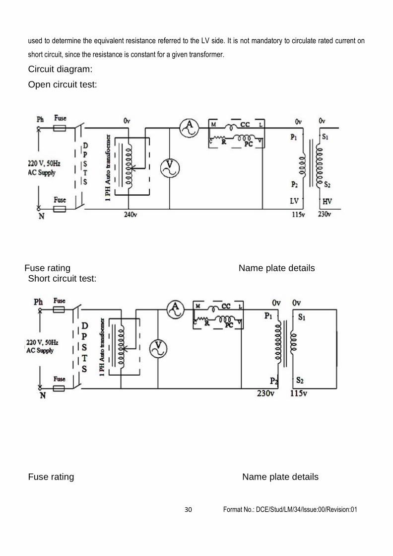
Circuit diagram:
Open circuit test:
Fuse rating Name plate details Short circuit test:
Fuse rating Name plate details
Format No.: DCE/Stud/LM/34/Issue:00/Revision:01 31
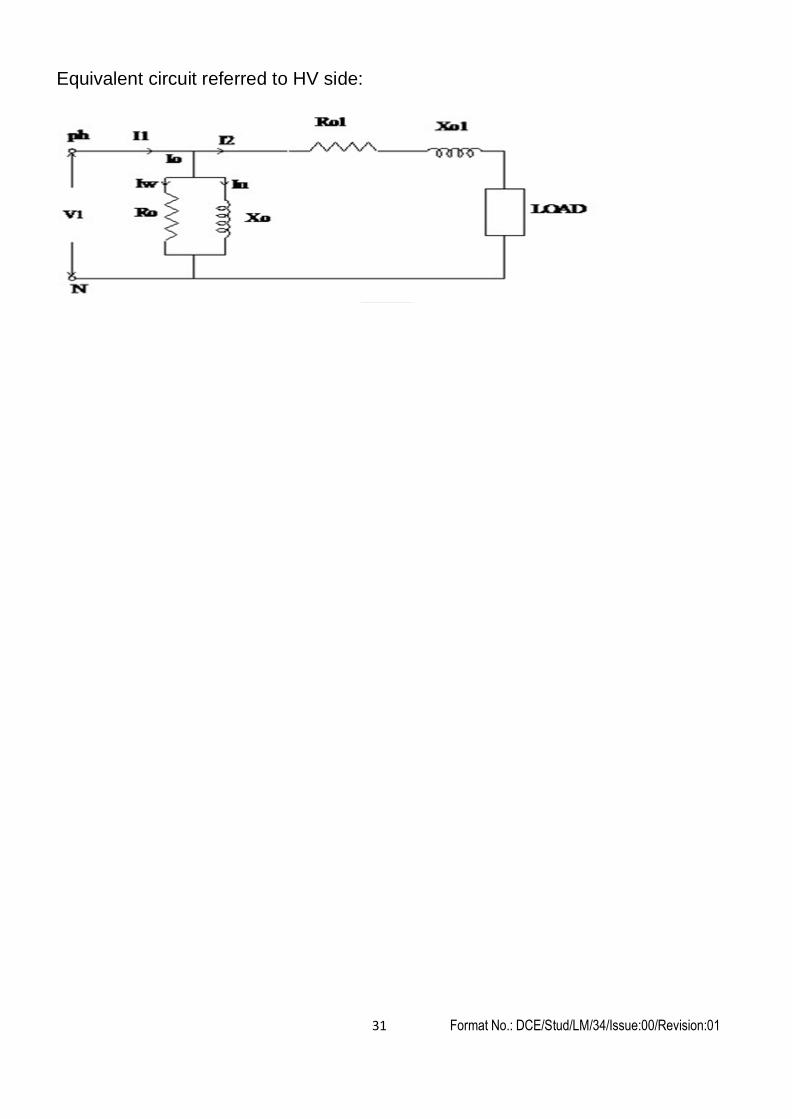
Equivalent circuit referred to HV side:
Format No.: DCE/Stud/LM/34/Issue:00/Revision:01 32
Precaution:
1. Keep the autotransformer in its minimum position at the time of starting
Procedure:
Open circuit test:
1. The connections are made as per the circuit diagram.
2. Keeping the H.V winding open and the autotransformer in its minimum position, the DPST switch is closed
3. By adjusting the autotransformer, the rated voltage is applied to the L.V winding of the transformer.
4. The ammeter (Io), and Wattmeter (Wo) readings are noted down.
5. Reduce the voltage to minimum value and open DPST switch .
6. After completing the experiment, constant loss, efficiency and regulations are calculated.
Short circuit test:
1. The circuit connections as per the circuit diagram.
2. Short circuiting the L.V winding and keeping the autotransformer in its minimum position, the DPST switch is
closed.
3. By adjusting the auto transformer, the rated current IHV is circulated through the H.V winding, (Note:
I H .V
KVA rating x1000
) VH.V
4. The voltmeter (Vsc) and the Wattmeter (Wsc) readings are noted down.
5. Reduce the voltage to minimum value and open DPST switch
Format No.: DCE/Stud/LM/34/Issue:00/Revision:01 33
Observation:
Test Voltage
(V) Current
(A) Power
(W)
O.C. TEST (On L.V side)
VO = IO= WO=
S.C. TEST (On H.V side)
VSC = ISC = WSC=
To predetermine the efficiency:
% Of Load
X
Output Power
(W)
Copper Loss
(W)
Total Loss
(W)
Input Power
(W)
Efficiency
(%)
To predetermine the % regulation:
Power Factor % Reg. For Lagging P.F % Reg. For Leading P.F
Calculation:
I. To obtain the equivalent circuit parameters referred to H.V side:
1. From the O.C test the constant loss (Iron loss) is noted Wc = Wo = Watt.
2. From the S.C test the full load copper loss is noted WF.L = Wsc = watt.
For a transformer, the equivalent circuit parameters can be determined either with respect to H.V side or with
respect to L.V side. If the parameters are estimated on the H.V side the resulting equivalent circuit is called H.V side
equivalent circuit of the transformer. From the O.C test Ro and Xo are calculated using the following expressions,
Format No.: DCE/Stud/LM/34/Issue:00/Revision:01 34
w
2
R0( L.V )
V0
I w
1 W0
X 0( L.V )
V0 Where,I I m
= I0
Coso
, Im
= I0
Sino
0= Cos
V0 I 0
Since these values are calculated with respect to L.V side (because O.C test is conducted on the L.V side), the
equivalent values of `Ro' and `Xo' as referred to H.V side are determined as
R0( H .V )
R 0(L.V) K
2
X 0( H .V )
X 0 (L.V) K
2
Where K = (secondary voltage) / (primary voltage)
K=115/230 for a step down operation; K = 230/115 for a step up operation.
Since we are assuming a step down operation K= 115/230 = 0.5.
R Wsc
,
Vsc
2 2
T ( H .V )
Isc
ZT ( H .V )
Isc
X T ( HV ) Z T(HV) - R T(HV)
RT(H.V) and XT(H.V) are the total equivalent resistance and reactance of the transformer as referred to the H.V side
whose values are calculated from the S.C test.
Now the H.V side equivalent circuit is drawn and the parameters values are mentioned in the circuit.
II. To predetermine the efficiency:
The percentage efficiency is then predetermined for different load conditions for a specified load power factor using
the expression,
Output power = x*KVA*cos*1000 Watt
Copper loss = x2 *WSC Watt
Total loss = Core loss (Wo) + Copper loss watt
Input power = Output Power + Total loss Watt
% Efficiency = (Output Power/Input Power)
x 100 %
Where `x' is the fraction of the full load which is 0.25 for 25% load, 0.5 for 50% load, 0.75 for 75% load, 1.0 for full
load and 1.25 for 125% load and cos is the load p.f (assumed as 0.8 lag).
The efficiency values so calculated are entered in the tabular column as shown below.
III. To predetermine the percentage regulation:
I H .V (R T(HV) Cos X T(HV) Sin )% Regulation =
VHV
*100 , Where ‘+’ for lagging power factor, ‘-‘for leading Power
factor, IH.V = Rated current on H.V side, VH.V = Rated voltage on H.V side
Format No.: DCE/Stud/LM/34/Issue:00/Revision:01 35
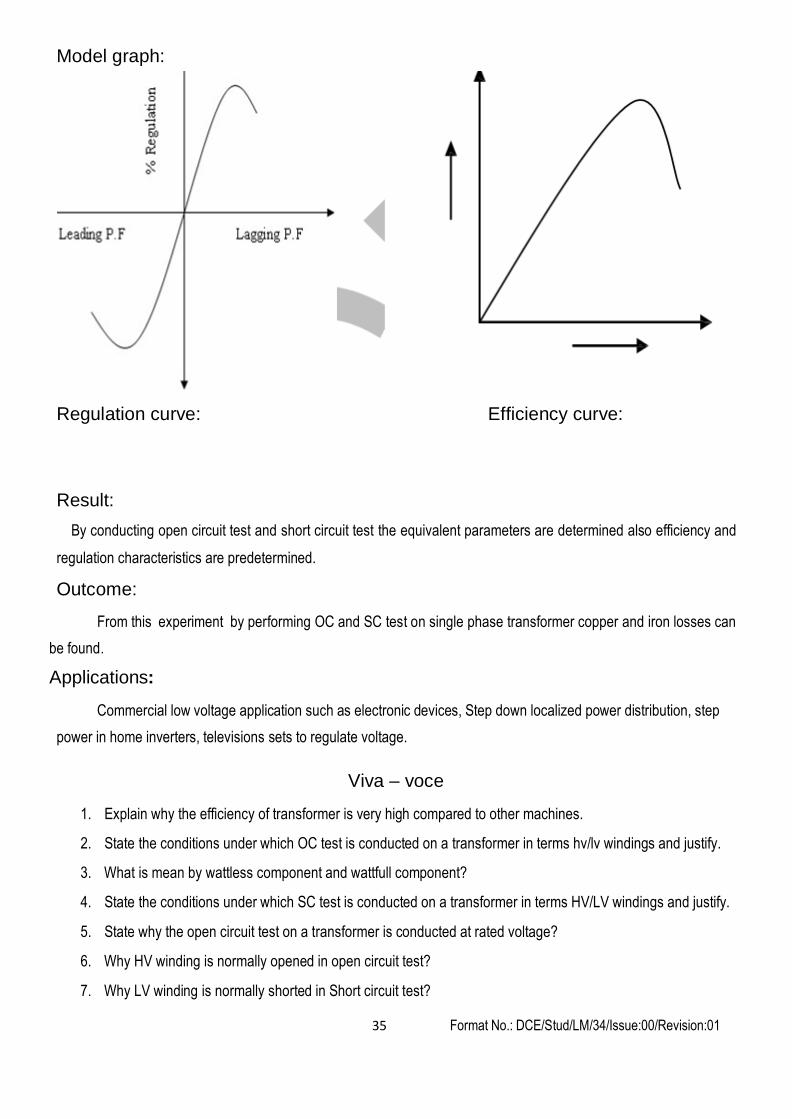
Model graph:
Regulation curve: Efficiency curve:
Result:
By conducting open circuit test and short circuit test the equivalent parameters are determined also efficiency and
regulation characteristics are predetermined.
Outcome:
From this experiment by performing OC and SC test on single phase transformer copper and iron losses can
be found.
Applications:
Commercial low voltage application such as electronic devices, Step down localized power distribution, step
power in home inverters, televisions sets to regulate voltage.
Viva – voce
1. Explain why the efficiency of transformer is very high compared to other machines.
2. State the conditions under which OC test is conducted on a transformer in terms hv/lv windings and justify.
3. What is mean by wattless component and wattfull component?
4. State the conditions under which SC test is conducted on a transformer in terms HV/LV windings and justify.
5. State why the open circuit test on a transformer is conducted at rated voltage?
6. Why HV winding is normally opened in open circuit test?
7. Why LV winding is normally shorted in Short circuit test?
Format No.: DCE/Stud/LM/34/Issue:00/Revision:01 36
Expt. No. 8 REGULATION OF THREE PHASE ALTERNATOR BY EMF AND MMF METHOD
Aim:
To predetermine the voltage regulation of the given three phase alternator at full load by EMF and MMF methods.
Apparatus required:
Sl. No. Name of the apparatus Range Type Quantity
1 Voltmeter (0 – 600 V) M. I. 1
2 Voltmeter (0 – 300 V) M. C. 1
3 Ammeter (0 – 10 A) M. I. 1
4 Ammeter (0 – 2 A) M. C. 1
5 Rheostat 220 Ω, 2 A - 1
6 Rheostat 950 Ω, 0.8 A - 1
7 Tachometer (0 – 10000 rpm) Digital 1
Theory:
The main purpose of predicting the regulation of alternator is to save energy it is also possible to obtain the
same when it is connected directly which will be limited to a particular rating. As the capacity increases, the
instruments range required to measure various parameters may not be available. Hence, the prediction of regulation
on no load tests is designed irrespective of the rating of the machine. `
In the EMF or synchronous impedance method the voltage drop due to armature leakage reactance and
armature reaction are taken as voltage drop due to synchronous reactance. This synchronous reactance means, the
reactance offered under stable operating condition i.e. the machine is delivering rated output at rated voltage. The
synchronous reactance is determined only at the rated voltage.
The MMF or Ampere turn method the voltage drop due to armature leakage reactance and armature reaction
are taken as voltage drop due to armature reaction. Normally, drop due to armature reaction is termed as field MMF
required to overcome the drop due to armature leakage reactance and armature reaction. In this method the drop
due to armature resistance should be taken to get accurate result.
Circuit diagram:
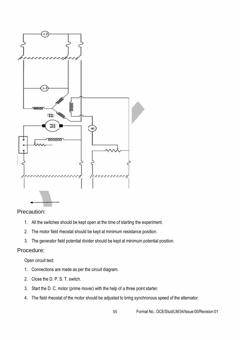
Format No.: DCE/Stud/LM/34/Issue:00/Revision:01 35
Precaution:
1. All the switches should be kept open at the time of starting the experiment.
2. The motor field rheostat should be kept at minimum resistance position.
3. The generator field potential divider should be kept at minimum potential position.
Procedure:
Open circuit test:
1. Connections are made as per the circuit diagram.
2. Close the D. P. S. T. switch.
3. Start the D. C. motor (prime mover) with the help of a three point starter.
4. The field rheostat of the motor should be adjusted to bring synchronous speed of the alternator.

Format No.: DCE/Stud/LM/34/Issue:00/Revision:01 36
5. Close the D. P. S. T. switch in the field circuit of the alternator.
6. The potential divider is varied gradually in steps.
7. At each step of variation, the field current and corresponding induced EMF are noted down.
8. The above procedure is repeated till the induced EMF reaches 110 % of its rated value.
9. Reduce the field current on the alternator side to zero value.
10. Reduce the speed by adjusting the motor field rheostat.
11. Open all the switches.
Short circuit test:
1. Connections are made as per the circuit diagram.
2. Close the D. P. S. T. switch.
3. Start the D. C. motor (prime mover) with the help of a three point starter.
4. The field rheostat of the motor should be adjusted to synchronous speed of the alternator.
5. Close the D. P. S. T. switch in the field circuit of the alternator.
6. The potential divider of the alternator field is varied till the ammeter in the alternator circuit reads rated current of the alternator, the corresponding field current is noted down.
7. Reduce the field current on the alternator side to zero value.
8. Reduce the speed by adjusting the motor field rheostat and open all switches.
Format No.: DCE/Stud/LM/34/Issue:00/Revision:01 37
Observation:
Open circuit test:
Sl. No. Field current, If (A) Line Voltage, EL (V) Phase Voltage, Eph (V)
Short circuit test:
Sl. No.
Field current, If (A)
Short circuit current, ISC (A)
Calculation:
Emf method:
The O. C. C. voltage and S. C. current with respect to alternator field current is plotted in the same graph. From the graph for the rated open circuit voltage the field current value is obtained. For this field current the short circuit current is obtained from the short circuit characteristics.
The synchronous impedance Zs = (O. C. voltage) / (S. C. current) for the same field current. Ohm
Synchronous reactance Xs = √(Zs2 – RS
2) Ohm
Where Rs – stator resistance per phase ohm
Es = √ (Vs cosφ + IsRs)2 + (Vs sinφ ± IsXs)2
+ for the lagging power factor
- For the leading power factor
In the above expression the power factor (cosΦ) can be assumed as unity and 0.2, 0.4, 0.6 and 0.8 for both lagging and leading.
Percentage Regulation = ((Es – Vs) / Vs) × 100
Vs – rated stator voltage per phase, V
For various power factors the full load regulation is tabulated and a graph is drawn between power factor and percentage regulation.
Mmf method:
Format No.: DCE/Stud/LM/34/Issue:00/Revision:01 38
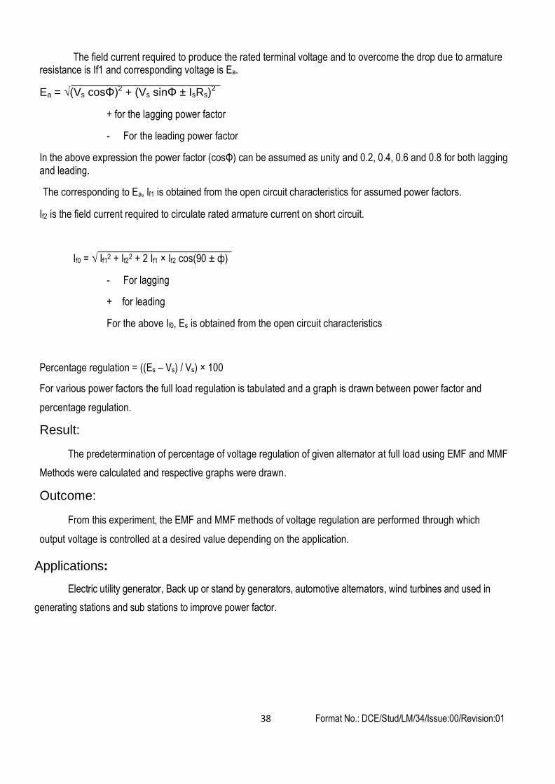
The field current required to produce the rated terminal voltage and to overcome the drop due to armature resistance is If1 and corresponding voltage is Ea.
Ea = √(Vs cosΦ)2 + (Vs sinΦ ± IsRs)2
+ for the lagging power factor
- For the leading power factor
In the above expression the power factor (cosΦ) can be assumed as unity and 0.2, 0.4, 0.6 and 0.8 for both lagging and leading.
The corresponding to Ea, If1 is obtained from the open circuit characteristics for assumed power factors.
If2 is the field current required to circulate rated armature current on short circuit.
If0 = √ If12 + If22 + 2 If1 × If2 cos(90 ± ф)
- For lagging
+ for leading
For the above If0, Es is obtained from the open circuit characteristics
Percentage regulation = ((Es – Vs) / Vs) × 100
For various power factors the full load regulation is tabulated and a graph is drawn between power factor and
percentage regulation.
Result:
The predetermination of percentage of voltage regulation of given alternator at full load using EMF and MMF
Methods were calculated and respective graphs were drawn.
Outcome:
From this experiment, the EMF and MMF methods of voltage regulation are performed through which
output voltage is controlled at a desired value depending on the application.
Applications:
Electric utility generator, Back up or stand by generators, automotive alternators, wind turbines and used in
generating stations and sub stations to improve power factor.

Format No.: DCE/Stud/LM/34/Issue:00/Revision:01 39
Viva - voce
1. What do you mean by synchronous reactance?
2. What is meant by synchronous impedance of an Alternator?
3. Why synchronous impedance is determined at its rated voltage?
4. What is the necessity for predetermination of voltage regulation?
5. How synchronous impedance is calculated from OCC and SCC?
6. Why is the synchronous impedance method of estimating voltage regulation considered as pessimistic
method?
7. Why is the MMF method of estimating the voltage regulation considered as the optimistic method?
8. What is the assumption made in the Synchronous Impedance method?
9. What is the assumption made in the Ampere Turn method method?
10. Is the synchronous impedance constant or variable for the given machine explain.
Format No.: DCE/Stud/LM/34/Issue:00/Revision:01 40
Expt. No. 9 LOAD TEST ON THREE PHASE INDUCTION MOTOR
Aim:
To obtain the performance characteristics of given three phase induction motor by conducting load test
Apparatus required:
Sl. No. Name of the apparatus Range Type Quantity
1 Wattmeter 600 V, 10 A UPF 2
2 Voltmeter (0 – 600 V) M. I. 1
3 Ammeter (0 – 10 A) M. I. 1
4 Tachometer (0 – 10000 rpm) Digital 1
Theory:
The three phase induction motor operates on the principle of electromagnetic induction. When a three phase
voltage is applied to the three phase winding, a revolving magnetic field. This in turn interacts with rotor and
produces an induced voltage in the rotor by mutual induction principle, which in turn circulates current. Since the
rotor conductors are short circuited. The rotor current and stator flux inter act and produces mechanical force making
the rotor to rotate.
In order to study the performance of the induction motor, the rotor is fitted with brake drum, which develops
frictional force through a belt being measured by two spring balances. By applying the frictional force various
parameters such as input power from the power factor, line current, torque and slip are calculated.
Format No.: DCE/Stud/LM/34/Issue:00/Revision:01 41
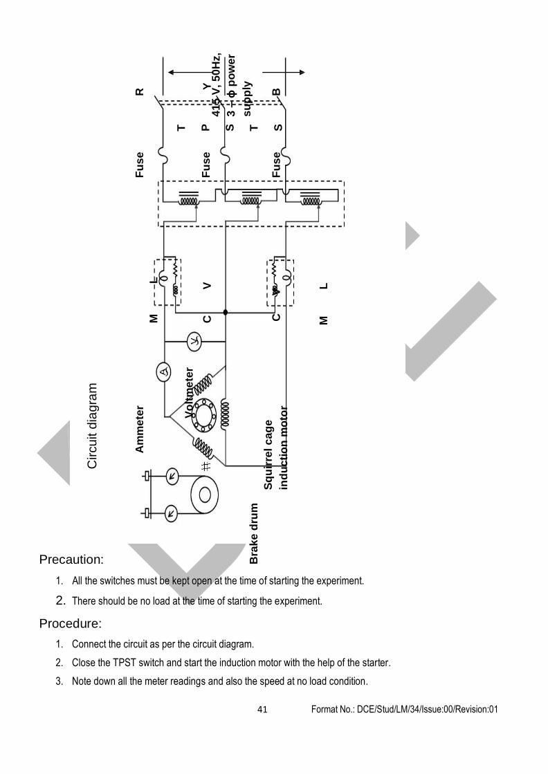
Circuit d
iagra
m
Am
me
ter
Fu
se
R
M
L
T
Vo
ltm
ete
r
P
Fu
se
C
V
Y
41
5 V
, 5
0H
z,
3 –
ϕ p
ow
er
su
pp
ly
S
Bra
ke
dru
m
T
Sq
uir
rel
ca
ge
ind
uc
tio
n m
oto
r C
V
F
us
e
B
S
M
L
Precaution:
1. All the switches must be kept open at the time of starting the experiment.
2. There should be no load at the time of starting the experiment.
Procedure:
1. Connect the circuit as per the circuit diagram.
2. Close the TPST switch and start the induction motor with the help of the starter.
3. Note down all the meter readings and also the speed at no load condition.

Format No.: DCE/Stud/LM/34/Issue:00/Revision:01 42
Observ
atio
n:
1 2
4. Apply the load on the break drum in steps.
5. At each step of loading, note down all the meter readings and speed.
6. Repeat the above procedure till the ammeter reads the rated current of the motor.
7. Remove the load on the brake drum and switch off the supply by opening the TPST.
Cos
φ
Effi
cien
cy
(%)
Slip
(%)
Out
put
Pow
er
(W)
Tor
que
(N m
)
(W1
+
W2)
(W)
(S1
–S2)
W2
(W)
W1
(W)
Spe
ed
(rpm
)
Spr
ing
Bal
ance
S
S
Cur
rent
(A)
Vol
tage
(V)
Sl.
No.
Format No.: DCE/Stud/LM/34/Issue:00/Revision:01 43
Calculation:
Torque, T = (S1 – S2) × 9.81 × r Newton meter.
Output power, P = 2π N T / 60 Watt
Input power = W1 + W2
% Efficiency, η = (Output power / Input power.) × 100
% slip, s = ((NS - N) / NS) × 100
cosφ = Input power / ( 3 VsIs)
Graph
Where,
NS – Synchronous speed of the machine in rpm.
N – Speed of the rotor in rpm.
r – Radius of the brake drum in the meter
S1 – Spring balance in kg.
S2 – Spring balance in kg.
Vs – Line Voltage in V
Is – Line current in A
Output Vs % Efficiency
Output Vs % Slip, N
Output Vs Line current, IL
Output Vs Power factor, cosφ
Output Vs Torque
Result:
Thus the load test on the three phase squirrel cage induction motor was done and the performance characteristics
were drawn.
Outcome:
By doing this experiment, the performance characteristics of three phase squirrel cage induction motor was
understood.
Application:
1. Three phase squirrel cage induction motor are used in the following applications Cooling fans to cool large machines

Format No.: DCE/Stud/LM/34/Issue:00/Revision:01 44
Exhaust fans at chimneys of power plant
Printing machines
Rolling mills
2. Procedure is being used in the manufacturing industry to determine the economical operation of the machine at its rated load condition.

Format No.: DCE/Stud/LM/34/Issue:00/Revision:01 45
Viva - voce
1. Why do we need starter for the induction motor?
2. Why the induction motor will not run at synchronous speed?
3. What do you understand the term slip and slip speed of an induction motor?
4. At light loads, one of the wattmeter will read negative. Why?
5. As the load increases the power factor increase. Why?
6. How the energy conversion takes place in this experiment?
7. Name the starting methods of an induction motor?
8. What are the advantages of slip ring induction motor over squirrel cage induction motor?
9. What are the advantages of squirrel cage induction motor over slip ring induction motor?
10. What is the condition for maximum efficiency for the induction motor?
11. Why the torque characteristics are straight line (Linear)?
Format No.: DCE/Stud/LM/34/Issue:00/Revision:01 46
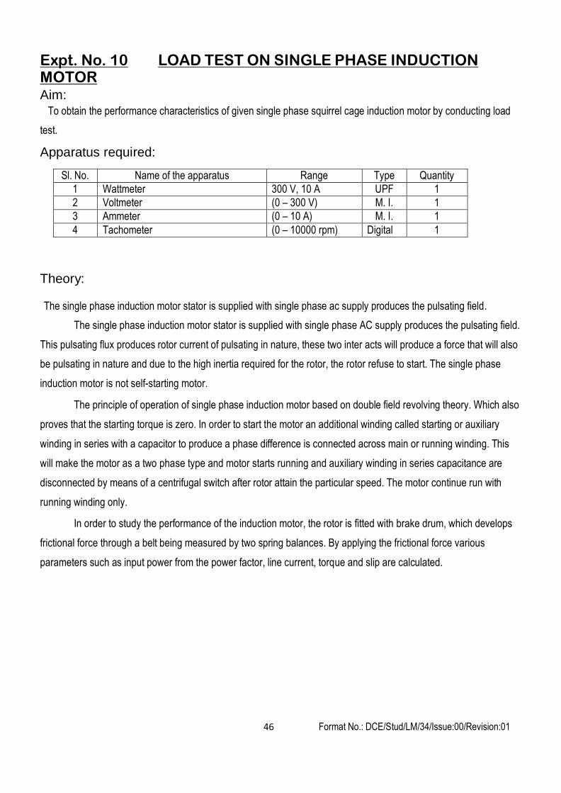
Expt. No. 10 LOAD TEST ON SINGLE PHASE INDUCTION MOTOR Aim:
To obtain the performance characteristics of given single phase squirrel cage induction motor by conducting load
test.
Apparatus required:
Sl. No. Name of the apparatus Range Type Quantity
1 Wattmeter 300 V, 10 A UPF 1
2 Voltmeter (0 – 300 V) M. I. 1
3 Ammeter (0 – 10 A) M. I. 1
4 Tachometer (0 – 10000 rpm) Digital 1
Theory:
The single phase induction motor stator is supplied with single phase ac supply produces the pulsating field.
The single phase induction motor stator is supplied with single phase AC supply produces the pulsating field.
This pulsating flux produces rotor current of pulsating in nature, these two inter acts will produce a force that will also
be pulsating in nature and due to the high inertia required for the rotor, the rotor refuse to start. The single phase
induction motor is not self-starting motor.
The principle of operation of single phase induction motor based on double field revolving theory. Which also
proves that the starting torque is zero. In order to start the motor an additional winding called starting or auxiliary
winding in series with a capacitor to produce a phase difference is connected across main or running winding. This
will make the motor as a two phase type and motor starts running and auxiliary winding in series capacitance are
disconnected by means of a centrifugal switch after rotor attain the particular speed. The motor continue run with
running winding only.
In order to study the performance of the induction motor, the rotor is fitted with brake drum, which develops
frictional force through a belt being measured by two spring balances. By applying the frictional force various
parameters such as input power from the power factor, line current, torque and slip are calculated.
Form
at No.: D
CE
/Stud/LM
/34/Issue:00/Revision:01
45
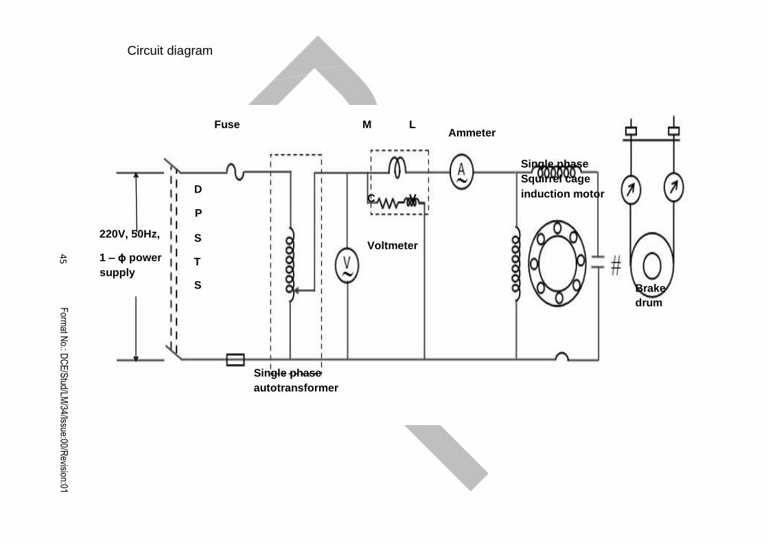
Circuit diagram
Fuse M L Ammeter
D
P
220V, 50Hz, S
1 – ϕ power T supply
S
C V
Voltmeter
Single phase
Squirrel cage
induction motor
Brake
drum
Single phase
autotransformer

Format No.: DCE/Stud/LM/34/Issue:00/Revision:01 46
Precaution:
1. All the switches must be kept open at the time of starting the experiment.
2. There should be no load at the time of starting the experiment.
Procedure:
1. Connect the circuit as per the circuit diagram.
2. Close the DPST switch and start the induction motor with the help of the starter.
3. Note down all the meter readings and also the speed at no load condition.
4. Apply the load on the break drum in steps.
5. At each step of loading, note down all the meter readings and speed.
6. Repeat the above procedure till the ammeter reads the rated current of the motor.
7. Remove the load on the brake drum and switch off the supply by opening the DPST.

Format No.: DCE/Stud/LM/34/Issue:00/Revision:01 47
Observ
atio
n:
Cos
φ
Effi
cien
cy
(%)
S
lip
(%)
Out
put
Pow
er
(W)
Tor
qu
e (N
W,In
put
pow
er
(W)
(S1
–S2)
Spe
ed
(rpm
)
Spr
ing
Bal
ance
S2
S1
Cur
rent
(A)
Vol
tage
(V)
Sl.
No.
Calculation:
Torque, T = (S1 – S2) × 9.81 × r Newton meter.
Output power, P = 2π N T / 60 Watt
Input power = W watts
% Efficiency, η = (Output power / Input power.) × 100
% slip, s = ((NS - N) / NS) × 100
Format No.: DCE/Stud/LM/34/Issue:00/Revision:01 48
cosφ = Input power / (VsIs)
Where,
Graph
NS – Synchronous speed of the machine in rpm.
N – Speed of the rotor in rpm.
r – Radius of the brake drum in the meter
S1 – Spring balance in kg.
S2 – Spring balance in kg.
Vs – Phase Voltage in V
Is – phase current in A
Output Vs % Efficiency
Output Vs % Slip, N
Output Vs Line current, IL
Output Vs Power factor, cosφ
Output Vs Torque
Result:
Thus the load test on the single phase induction motor was done and the performance characteristics were drawn.
Outcome:
By doing this experiment the performance characteristics of single phase induction motor was analyzed under
loads.
Application:
1. Single phase induction motors are used in the following applications Air conditioner and refrigerator
Ceiling fans and blowers
Machine tool drive
Pump drive
2. Procedure is being used in the manufacturing industry to determine the economical operation of the machine at its rated load condition.
Viva - voce
1. Why single phase induction motor is not self-starting one?
2. Mention the methods of starting the single phase induction motor.

Format No.: DCE/Stud/LM/34/Issue:00/Revision:01 49
3. What is double field revolving theory? What do you mean by the term forward rotating field and backward
rotating field?
4. What is the centrifugal switch? And state its function.
5. The power factor of single phase induction motor is less when compared to three phase induction motor.
Why?
6. Name the applications of single phase induction motor.
Format No.: DCE/Stud/LM/34/Issue:00/Revision:01 50
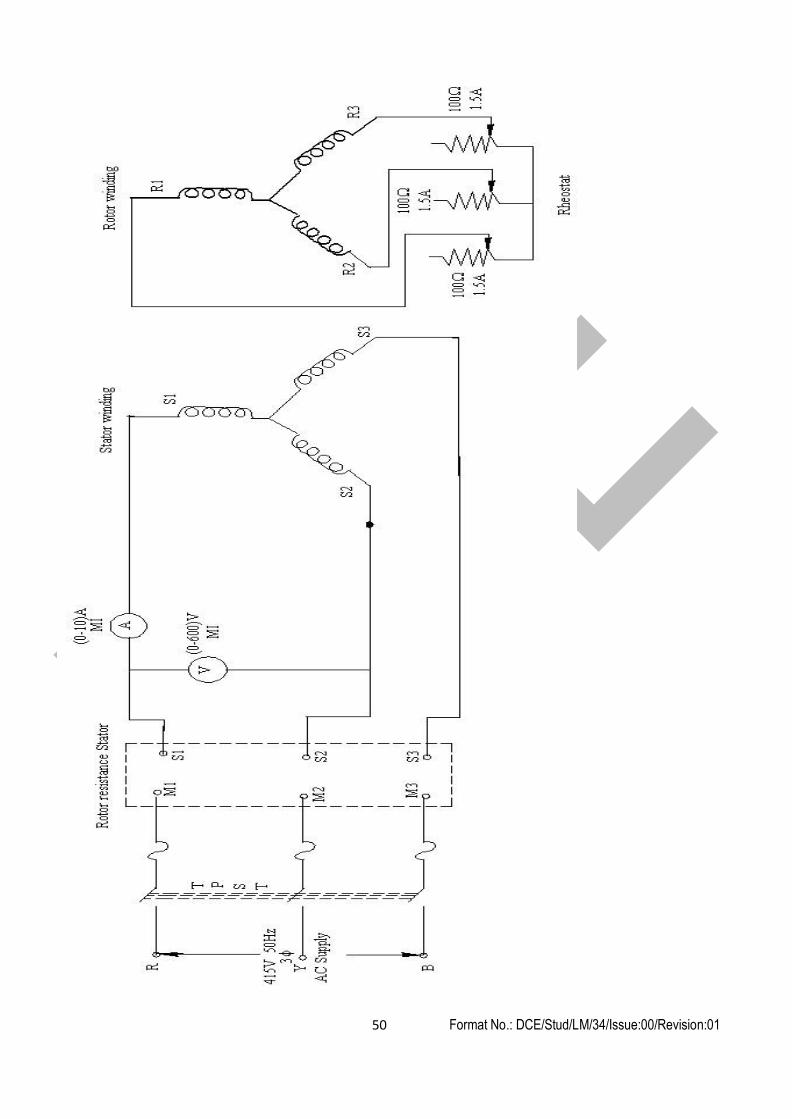
Expt. No.11 LOAD TEST ON THREE PHASE SLIP RING INDUCTION MOTOR
Aim:
test
To obtain the performance characteristics of given three phase slip ring induction motor by conducting load
Apparatus required:
Sl. No. Name of the apparatus Range Type Quantity
1 Wattmeter 600 V, 10 A UPF 2
2 Voltmeter (0 – 600 V) M. I. 1
3 Ammeter (0 – 10 A) M. I. 1
4 Tachometer (0 – 10000 rpm) Digital 1
5 Three phase Auto Transformer (0 – 470 V) - 1
Precaution:
1. All the switches must be kept open at the time of starting the experiment.
2. There should be no load at the time of starting the experiment.
3. Auto Transformer should be kept open at minimum potential position at the time of starting the experiment.
Procedure:
1. Connections are made as per the circuit diagram.
2. Close the TPST switch.
3. Auto Transformer is varied till the voltmeter reads the rated voltage of the motor.
4. All the meters readings should be noted at no load condition.
5. Apply the load on the break drum in steps.
6. At each step of loading all the meter readings should be noted.
7. The above procedure is repeated till the ammeter reads the rated current of the motor.
50 Format No.: DCE/Stud/LM/34/Issue:00/Revision:01

Sl. No.
Voltage
(V)
Current
(A)
Spring
Balance
Speed
(rpm)
W1
(W)
W2
(W)
(S1 –S2)
(W1 + W2)
(W)
Torque
(N m)
Input
Power
(W)
Output
Power
(W)
Slip
(%)
Efficiency
(%)
cosφ
S
S
Form
at No.: D
CE
/Stud/LM
/34/Issue:00/Revision:01
51
Observation:
1 2
Format No.: DCE/Stud/LM/34/Issue:00/Revision:01 52
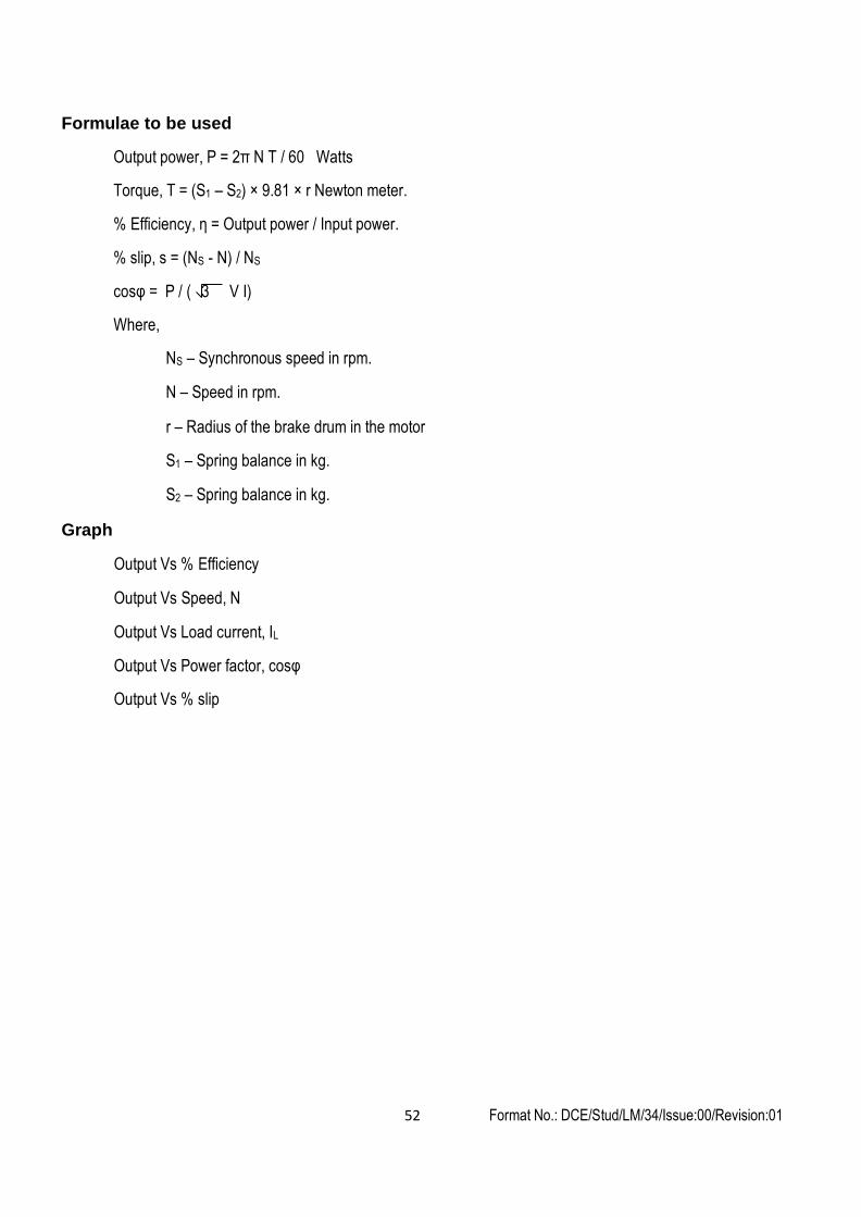
Formulae to be used
Output power, P = 2π N T / 60 Watts
Torque, T = (S1 – S2) × 9.81 × r Newton meter.
% Efficiency, η = Output power / Input power.
% slip, s = (NS - N) / NS
cosφ = P / ( 3 V I)
Where,
Graph
NS – Synchronous speed in rpm.
N – Speed in rpm.
r – Radius of the brake drum in the motor
S1 – Spring balance in kg.
S2 – Spring balance in kg.
Output Vs % Efficiency
Output Vs Speed, N
Output Vs Load current, IL
Output Vs Power factor, cosφ
Output Vs % slip

Format No.: DCE/Stud/LM/34/Issue:00/Revision:01 53
Result:
Thus the load test on the three phase slip ring induction motor was done and the performance characteristics
were drawn.
Outcome:
From this experiment, the load test on squirrel cage induction motor was performed through which the
performance characteristics of three phase squirrel cage induction motor was understood.
Applications:
High power applications like traction ,conveyor belts and lifts.
Format No.: DCE/Stud/LM/34/Issue:00/Revision:01 54
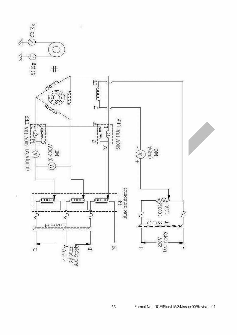
Expt. No. 12 V AND INVERTED V CURVES OF SYNCHRONOUS MOTOR
Aim:
To draw V and inverted V curves of given synchronous motor
Apparatus required:
Sl. No. Name of the apparatus Range Type Quantity
1 Voltmeter (0 – 600 V) M. I. 1
2 Ammeter (0 – 10 A) M. I. 1
3 Ammeter (0 – 2 A) M. C. 1
4 Wattmeter 600 V, 10 A UPF 1
5 Tachometer (0 – 10000 rpm) Digital 1
6 Three phase Auto Transformer (0 – 470 V) - 1
7 Rheostat 950 Ω, 0.8 A - 1
Precaution:
1. All the switches should be kept open at the time of starting the experiment.
2. The potential divider in the field circuit of synchronous motor should be kept at minimum potential position.
Procedure:
1. Connections are made as per the circuit diagram.
2. Close the T. P. S. T. switch.
3. The auto transformer is varied gradually to start the motor.
4. The auto transformer is adjusted till the voltmeter reads the rated voltage of the synchronous motor.
5. Close the D. P. S. T. switch and increase the field current.
6. At no load condition, increase the field current in steps and note down the corresponding armature current.
7. The potential divider is brought to the minimum potential position.
8. Repeat the same procedure for different load conditions.
9. Reduce the load on the motor.
10. Reduce the field current to zero value.
11. Reduce voltage by varying auto transformer.
12. Open all the switches.
55 Format No.: DCE/Stud/LM/34/Issue:00/Revision:01
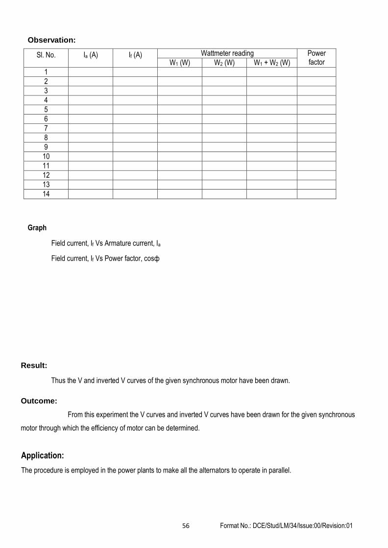
Observation:
Sl. No. Ia (A) If (A) Wattmeter reading Power factor W1 (W) W2 (W) W1 + W2 (W)
1
2
3
4
5
6
7
8
9
10
11
12
13
14
Graph
Field current, If Vs Armature current, Ia
Field current, If Vs Power factor, cosф
Result:
Thus the V and inverted V curves of the given synchronous motor have been drawn.
Outcome:
From this experiment the V curves and inverted V curves have been drawn for the given synchronous
motor through which the efficiency of motor can be determined.
Application:
The procedure is employed in the power plants to make all the alternators to operate in parallel.
56 Format No.: DCE/Stud/LM/34/Issue:00/Revision:01


![Electrical Machines Laboratory - Terco [English]...Induction Motor Squirrel Cage 10 Induction Motor Thermistor Protected 32 Laboratory Flexes with Safety Plugs 15,46,47 Load Capacitor](https://img.dokumen.tips/doc/110x75/6093fca788537a39d95478b2/electrical-machines-laboratory-terco-english-induction-motor-squirrel-cage.jpg)