Embed Size (px)
Citation preview

MSC Software
Università di Roma - Sapienza
Laboratorio Calcolo e Strutture
Esercitazione n. 2- Statica (Elementi 2D)
Laboratorio Calcolo e Strutture Esercitazione n. 2
“Strutture bidimensionali”
Ing. Mauro Linari
Pro ject Manager
MSC Software S.r. l .

MSC Software
Università di Roma - Sapienza
Laboratorio Calcolo e Strutture
Esercitazione n. 2- Statica (Elementi 2D)
Schematizzazione delle strutture Esempi di strutture modellabili con elementi bidimensionali

MSC Software
Università di Roma - Sapienza
Laboratorio Calcolo e Strutture
Esercitazione n. 2- Statica (Elementi 2D)
• Definition:
– A plate (or shell) is a structural element which
represents a component with one small
dimension and two large dimensions
• Plate and shell elements are used to model thin plates.
– A thin plate is one in which the thickness is
much less than the next larger dimension
(roughly 1/15).
• For linear analysis, MSC Nastran plate
elements assume classical engineering
assumptions of thin plate behavior
– The deflection of the mid-surface is small
compared with the thickness
– The mid-surface remains unstrained (neutral)
during bending (this applies to lateral loads,
not in-plane loads).
– The normal to the mid-surface remains normal
to the mid-surface during bending
Two-Dimensional Elements Plates and shells - Background
• An important fact about plate and shell
elements is that they have no stiffness
term for in-plane rotational dof.
‒ As such, if BAR or BEAM elements are
connected to a plate of shell, special modeling
effort is required.
• Some references on basic plate theory:
1. Theory of Plates and Shells, by S.
Timoshenko and S. Woinowsky-Krieger,
2nd ed., McGraw Hill, 1959
2. Stresses in Plates and Shells, by A. C.
Ugural, McGraw Hill, 1981

MSC Software
Università di Roma - Sapienza
Laboratorio Calcolo e Strutture
Esercitazione n. 2- Statica (Elementi 2D)
• TRIA3
Three-noded isoparametric flat plate element.
– Commonly used for mesh transitions. May have excessive stiffness particularly for membrane strain.
• QUAD4
Four-noded isoparametric flat plate element.
– Behaves well when irregularly shaped, good results can be obtained with skew angles up to 45 degrees
• TRIA6
Isoparametric triangle element with three corner and three midside grid points.
– Used in regions with curvature.
• QUAD8
Isoparametric element with four corner and four edge grid points.
‒ Useful for modeling singly-curved shells (e.g. cylinder).
‒ QUAD4 performs better for doubly curved shells (e.g.
sphere).
• SHEAR
Four-noded, shear and extensional force only element. Used for analyzing thin reinforced plates and shells.
– Commonly used with rod elements to analyze thin-skinned aircraft structures (best if rectangular).
• TRIAR
Three-noded isoparametic flat element.
– Companion to the QUADR element.
– Has R3 stiffness.
• QUADR
Four-noded isoparametric flat plate element.
– Less sensitive to distortion and yields better results for in-plane bending. Has R3 stiffness.
Two-Dimensional Elements MSC Nastran 2D Elements

MSC Software
Università di Roma - Sapienza
Laboratorio Calcolo e Strutture
Esercitazione n. 2- Statica (Elementi 2D)
• The QUAD4 element is the most commonly used plate element
• It is a 4-noded flat plate element
• It is capable of resisting both, in-plane and out-of-plane loads
• It is capable of modeling either plane strain or plane stress
• It has terms in its stiffness matrix to account for transverse shear
flexibility and also for membrane-bending coupling
• In-plane penalty bending stiffness term is added with a default
PARAM,K6ROT,100. (see section 5 for further details)
• PARAM,SNORM,20. is a default as well (see section 5)
Two-Dimensional Elements The QUAD4 Element – General Behaviors

MSC Software
Università di Roma - Sapienza
Laboratorio Calcolo e Strutture
Esercitazione n. 2- Statica (Elementi 2D)
• Element force output includes:
– Fx,Fy : Membrane force per unit lenght
– Fxy : Membrane shear force per unit length
– Mx,My : Bending moments per unit length
– Mxy : Twisting moment per unit length
– Vx,Vy : Transverse shear forces per unit length
• Element Stress output includes:
– Stress components: sx, sy, txy,
(at center - optionally at corners)
• Element force and stress sign convention
Two-Dimensional Elements The QUAD4 Element – Output Data

MSC Software
Università di Roma - Sapienza
Laboratorio Calcolo e Strutture
Esercitazione n. 2- Statica (Elementi 2D)
Two-Dimensional Elements QUAD4 Element definition

MSC Software
Università di Roma - Sapienza
Laboratorio Calcolo e Strutture
Esercitazione n. 2- Statica (Elementi 2D)
• The element coordinate system
– Is defined based on the order and location of the connecting points
– Defines positive sense of normal pressures applied to the element
– Used to define layers of a composite material
– Used to interpret the element output forces and stresses (element output is in
the element coordinate system by default for these elements)
Element x-axis
It bisects the angle 2a. Positive direction is from G1
towards G2.
Element y-axis
It is perpendicular to the element x-axis and lies in the
plane defined by G1, G2, G3, and G4. Positive direction
is from G1 towards G4.
Element z-axis
It is normal to the x-y plane of the element. Positive
sense is defined by the right-hand rule and the ordering
of the connected grids.
Two-Dimensional Elements QUAD4 Element coordinate system

MSC Software
Università di Roma - Sapienza
Laboratorio Calcolo e Strutture
Esercitazione n. 2- Statica (Elementi 2D)
• Are defined using either a PSHELL, PCOMP (composite), PCOMPG
(composite) or PLPLANE (nonlinear) entry.
Field Contents
PID Property identification number
MID1 Material identification number for membrane behavior (integer > 0 or blank)
T Plate or membrane thickness
MID2 Material identification number for bending behavior (integer > 0 or blank, MID2 = -1 represents plane strain) NOTE: THE DEFAULT FOR MID2 IS NOT TO INCLUDE THE BENDING STIFFNESS. FOR MOST MODELS, MID2 SHOULD NOT BE BLANK
12I/T3 Normalized bending inertia per unit length (real or blank, default = 1.0). The default value is correct for solid, homogeneous
plates.
Field Contents
MID3 Material identification number for transverse shear behavior (integer > 0 or
blank)
TS/T Transverse shear thickness divided by membrane thickness (default = .833333). The default value is correct for solid, homogeneous plates.
NSM Nonstructural mass per unit area (real)
Z1,Z2 Stress recovery distances for bending (real, default Z1 = -0.5T, Z2 = +0.5T)
MID4 Material identification number to define coupling between membrane and bending deformation
Two-Dimensional Elements QUAD4 Element properties

MSC Software
Università di Roma - Sapienza
Laboratorio Calcolo e Strutture
Esercitazione n. 2- Statica (Elementi 2D)
• The QUAD4 element can have in-plane, bending, and transverse
shear behavior. The element mechanical behavior is specified by the
presence or absence of a material ID number in the appropriate
field(s) on the PSHELL entry.
• To model a membrane plate, use only MID1
• To model a plate with bending stiffness only, use only MID2
• For bending with transverse shear flexibility, use MID2 and MID3
• Note: Mass is not calculated if MID1 is blank.
Two-Dimensional Elements QUAD4 Element properties

MSC Software
Università di Roma - Sapienza
Laboratorio Calcolo e Strutture
Esercitazione n. 2- Statica (Elementi 2D)
• Use MID3 to include an extra shear term in the element stiffness
calculations (i.e. includes transverse shear flexibility).
Two-Dimensional Elements QUAD4 Element properties
• For a solid homogeneous plate, MID1, MID2, and MID3 should reference
the same material ID
• MID4: The MID4 field (bending and membrane deformation coupling) should
be defined only if the element’s cross section is unsymmetric.
Default is blank = symmetric cross section.

MSC Software
Università di Roma - Sapienza
Laboratorio Calcolo e Strutture
Esercitazione n. 2- Statica (Elementi 2D)
Two-Dimensional Elements Patran - QUAD4 Element Definition: Thin and Thick Shell
Only one material can be selected
MID1 = MID2 = MID3
One material for each QUAD4 behavior
MID1 ≠ MID2 ≠ MID3

MSC Software
Università di Roma - Sapienza
Laboratorio Calcolo e Strutture
Esercitazione n. 2- Statica (Elementi 2D)
Two-Dimensional Elements Patran - QUAD4 Element Definition: Bending/Membrane Panel
Only one material can be selected
Only MID2 ≠ 0
Only One material can be selected
Only MID1 ≠ 0

MSC Software
Università di Roma - Sapienza
Laboratorio Calcolo e Strutture
Esercitazione n. 2- Statica (Elementi 2D)
Two-Dimensional Elements Patran - QUAD4 Element Definition: Plane Strain/Plane Stress
MID1 ≠ 0 and MID2 = -1 A different property
card is generated
Only one material can be selected
Only One material can be selected

MSC Software
Università di Roma - Sapienza
Laboratorio Calcolo e Strutture
Esercitazione n. 2- Statica (Elementi 2D)
Notice that
the in
-pla
ne r
ota
tion
is
constr
ain
ed
for
the m
odel
positio
ned in the x
-y p
lane.
Two-Dimensional Elements QUAD4 Example

MSC Software
Università di Roma - Sapienza
Laboratorio Calcolo e Strutture
Esercitazione n. 2- Statica (Elementi 2D)
DISP = ALL Displacement for all Grid Points
FORCE = ALL Element forces at the center only (default)
Two-Dimensional Elements QUAD4 Example – Force Output

MSC Software
Università di Roma - Sapienza
Laboratorio Calcolo e Strutture
Esercitazione n. 2- Statica (Elementi 2D)
Stress = ALL Element stress at center only (default)
STRESS(BILIN) = ALL Element stress at center plus extrapolated at the 4 nodal positions
Two-Dimensional Elements QUAD4 Example – STRESS Output
sHVM = [(3.024E6)2 – (3.024E6)(2.268E5) + (2.268E5)2] ½ = 2.917E6
STRAIN(BILIN,FIBER) = ALL element strain at the fiber distances at center plus extrapolated at the 4 nodal positions

MSC Software
Università di Roma - Sapienza
Laboratorio Calcolo e Strutture
Esercitazione n. 2- Statica (Elementi 2D)
• The PCOMP property entry may be used when the element is a
composite consisting of layers of unidirectional fibers.
• The information on the PCOMP entry includes the thickness,
orientation, and material identification of each layer.
– This information is used within MSC Nastran to compute the entries of
a PSHELL entry, which should not be simultaneously entered by the
user for the same element(s).
• Special layer-by-layer output is provided when the PCOMP
option is used.
– Putting the NASTRAN PRTCOMP=1 system cell at the top of the .dat
file along with “echo=sort” will print the equivalent PSHELL and MAT2
entries.
Two-Dimensional Elements QUAD4 alternate property definition

MSC Software
Università di Roma - Sapienza
Laboratorio Calcolo e Strutture
Esercitazione n. 2- Statica (Elementi 2D)
• Si considera una piastra (Lunghezza = 1m, Larghezza = 0.5 m) sottoposta
alle seguenti condizioni di carico
– Caso 1: Carico concentrato in uno degli angoli dell’estremo libero (F = 1000N)
– Caso 2: Carico di pressione uniforme (p =1000 Pa)
– Caso 3: Carico di pressione variabile sulla piastra (si consideri il valore di pressione
del caso precedente come riferimento
• Lato incastrato: pA=0.75, pB=1p
• Lato incastrato: pC=0.25, pD=0,5p
Esempio Applicativo Statico Lineare Piastra Incastrata soggetta a diverse condizioni di carico
A
B
C
D
Materiale: Acciaio E = 2.06e11 N/m2 V = 0.3 Ρ = 7800 K/m3
L1 = 2 m L2 = 3 m t= 4 mm

MSC Software
Università di Roma - Sapienza
Laboratorio Calcolo e Strutture
Esercitazione n. 2- Statica (Elementi 2D)
Esempio Applicativo Statico Lineare Costruzione della geometria e definizione dei vincoli
1 – GEOMETRIA (Item: Geometry)
2 – VINCOLI (Item: Load/BC)
I vincoli si applicano direttamente sulla geometria (edge)
MSC Software
Università di Roma - Sapienza
Laboratorio Calcolo e Strutture
Esercitazione n. 2- Statica (Elementi 2D)
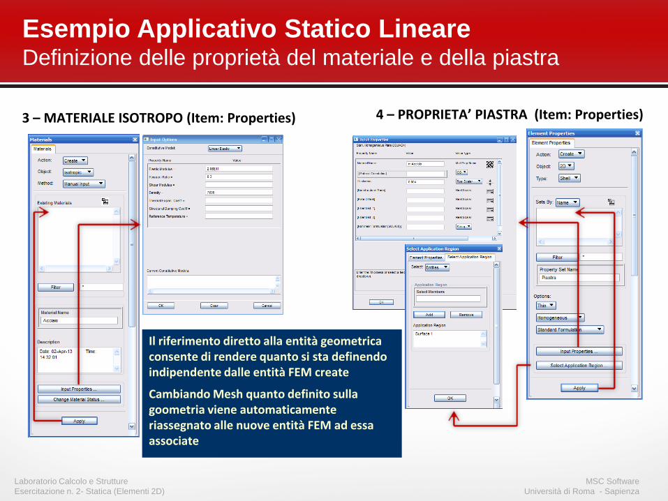
Esempio Applicativo Statico Lineare Definizione delle proprietà del materiale e della piastra
4 – PROPRIETA’ PIASTRA (Item: Properties) 3 – MATERIALE ISOTROPO (Item: Properties)
Il riferimento diretto alla entità geometrica consente di rendere quanto si sta definendo indipendente dalle entità FEM create
Cambiando Mesh quanto definito sulla goometria viene automaticamente riassegnato alle nuove entità FEM ad essa associate

MSC Software
Università di Roma - Sapienza
Laboratorio Calcolo e Strutture
Esercitazione n. 2- Statica (Elementi 2D)
Esempio Applicativo Statico Lineare Costruzione della mesh
6 – Creazione della mesh (Item: Meshing) 5 – Definizione dei ‘mesh seed’ (Item: Meshing)
20
ele
me
nti
su
ed
ge 4
del
la S
urf
ace
1
30
ele
men
ti s
u e
dge
3 d
ella
Su
rfac
e 1
Proprietà, vincoli e carichi
precedentemente associati alla
superficie vengono associati agli
elementi su di essa costruiti

MSC Software
Università di Roma - Sapienza
Laboratorio Calcolo e Strutture
Esercitazione n. 2- Statica (Elementi 2D)
Patran – Discretizzazione della struttura Verifica congruenza mesh su superfici adiacenti
Si ‘Meshano’ tutte le superfici Su ciascuna delle superfici vengono generati degli elementi ed in particolare per ciascun bordo vengono creati dei nodi sovrapposti La verifica dei bordi liberi evidenzia
chiaramente la non continuita della discretizzazione in corrispondenza di tutti i bordi comuni delle superfici
Si utilizza la funzione di ‘equivalenza’ dei nodi per connettere gli elementi adiacenti in corrispondenza dei bordi delle superfici
La verifica finale sui bordi evidenzia come l’operazione di equivalenza ristabilito la congruenza tra le mesh create sulle diverse superfici .
GLI UNICI BORDI LIBERI SONO CORRETTAMENTE QUELLI NON IN CONTATTO CON ALCUNA DELLE SUPERFICI
Meshing/Create/Mesh
Meshing/Verify/Boundaries
Meshing/Equivalence
Meshing/Verify/Boundaries
• Si ricorda che ….

MSC Software
Università di Roma - Sapienza
Laboratorio Calcolo e Strutture
Esercitazione n. 2- Statica (Elementi 2D)
Esempio Applicativo Statico Lineare Definizione dei carichi – Verifica direzione normali elementi 2D
• Dovendo definire dei carichi di pressione è consigliabile eseguire
preliminarmente una verifica della direzione delle normali degli elementi
‒ La conoscenza della normale all’elemento consente di definirne il top (lato elemento
nella direzione della normale) ed conseguentemente il bottom
‒ Corretta applicazione del carico di pressione
TOP
BOTTOM
Si c
on
sigl
ia d
i eff
ett
uar
e q
ue
sta
veri
fica
dir
ett
ame
nte
sulla
en
tità
ge
om
etr
ica
in q
uan
to p
iù f
acilm
en
te
con
tro
llab
ile e
d e
ven
tual
me
nte
mo
dif
icab
ile
Step 7
Item: Meshing
Item: Geometry

MSC Software
Università di Roma - Sapienza
Laboratorio Calcolo e Strutture
Esercitazione n. 2- Statica (Elementi 2D)
Esempio Applicativo Statico Lineare Definizione dei carichi – Carico Concentrato
• Carico concentrato in nodo d’angolo del lato corto ‘libero’ della piastra
Il carico verrà automaticamente
assegnato al ‘Load Case’ Corrente.
Opportune operazioni di creazione o modifica di ‘Load
Case ‘ consentiranno eventualmente di definire
correttamente le condizioni di carico e vincolo desiderate
Item: Load/BC
Step 8

MSC Software
Università di Roma - Sapienza
Laboratorio Calcolo e Strutture
Esercitazione n. 2- Statica (Elementi 2D)
Esempio Applicativo Statico Lineare Definizione dei carichi – Carico di pressione uniforme
Da notare come convenzionalmente
negli elementi 2D la pressione è positiva
se è diretta verso l’interno dell’elemento
considerandola definita nel lato (TOP o
BOTTOM) di applicazione
Zel
p
BOTTOM
TOP (p > 0)
(p < 0)
Item: Load/BC
Step 9

MSC Software
Università di Roma - Sapienza
Laboratorio Calcolo e Strutture
Esercitazione n. 2- Statica (Elementi 2D)
Esempio Applicativo Statico Lineare Definizione dei carichi – Carico di pressione non costante
• La definizione di un carico di pressione applicato
in modo non uniforme sulla struttura comporta la
definizione di un FIELD di tipo spaziale.
• I ‘FIELDS’ in PATRAN sono delle funzioni
utilizzate per definire la variabilità di:
‒ Carichi
‒ Condizioni di vincolo
‒ Proprietà del materiale
‒ Proprietà degli elementi
• Ci sono tre tipi di FIELDS
‒ Spaziali
‒ Non Spaziali
‒ Proprietà del materiale
Il concetto di ‘FIELD’

MSC Software
Università di Roma - Sapienza
Laboratorio Calcolo e Strutture
Esercitazione n. 2- Statica (Elementi 2D)
• In particolare il metodo da usare nel caso in
esame è quello che sfrutta la definizione del
FIELD in forma tabellare
‒ Il pannello si sviluppa nel piano XY per cui i valori di
pressione si definiscono sulla base delle coordinate
X ed Y dei punti di angolo del pannello stesso
Analisi al Transitorio di un cassone alare PATRAN – Definizione del carico: Il FIELD spaziale
P1 ≡ (0., 0., 0.)
P2 ≡ (2., 0., 0.)
P4 ≡ (0., 3., 0.)
P3 ≡ 2., 3., 0.)
• FIELD Name = Pressure_Distribution
2.0 3.0
0.0 0.0
Step 10

MSC Software
Università di Roma - Sapienza
Laboratorio Calcolo e Strutture
Esercitazione n. 2- Statica (Elementi 2D)
Esempio Applicativo Statico Lineare Definizione dei carichi – Carico di pressione non costante
Step 11

MSC Software
Università di Roma - Sapienza
Laboratorio Calcolo e Strutture
Esercitazione n. 2- Statica (Elementi 2D)
Esempio Applicativo Statico Lineare Patran – Definizione delle condizioni di carico

MSC Software
Università di Roma - Sapienza
Laboratorio Calcolo e Strutture
Esercitazione n. 2- Statica (Elementi 2D)
Esempio Applicativo Statico Lineare Impostazione dell’analisi
Selezione del tipo di analisi Definizione delle caratteristiche della singola condizione di carico
Definizione dell’output Selezione delle condizioni di carico da analizzare
Creazione input file

MSC Software
Università di Roma - Sapienza
Laboratorio Calcolo e Strutture
Esercitazione n. 2- Statica (Elementi 2D)
File di input MSC Nastran Executive e Case Control Deck
EXECUTIVE CONTROL DECK
SUB
CA
SE ≡
Co
nd
izio
ne
di c
aric
o
1
2
3
C a r i c h i
O u t p u t
V i n c o l i
CA
SE C
ON
TRO
L D
ECK
I comandi comuni ai vari sottocasi potrebbero essere posizionati al di sopra del primo sottocaso Quanto definito al di sopra del primo
sottocaso vale come default per tutti I sottocasi
Quanto dichiarato all’interno del singolo sottocaso vale solamente all’interno di esso
Relativamente all’identificativo del singolo sottocaso: Non deve essere necessariamente
definito come il successivo di quello del precedente
La sequenza degli identificativi dei sottocasi deve rispettare la sola condizione di essere creascente

MSC Software
Università di Roma - Sapienza
Laboratorio Calcolo e Strutture
Esercitazione n. 2- Statica (Elementi 2D)
File di input MSC Nastran Bulk Data Deck - Rappresentazione del modello ad elementi finiti
(G1)
(G2)
(G3)
(G4)
D e f i n i z i on e d e l l a n or m a l e a l l ’ e l e m e n t o
Note that there are two coordinate systems on the GRID entry:
– CP = “position” coordinate system - used to define the location in space
– CD = “displacement” coordinate system - used to measure the motion of the point and to define constraints at the point
These may be rectangular, cylindrical, or spherical systems
O u t p u t i n f i l e X D B
Ele
me
nti
2D
co
n
rela
tiv
e p
rop
rie
tà
CP CD
M a t e r i a l e
Da notare come nella scheda proprietà (PSHELL) siano stati attivati tutti i tipi di comportamenti dell’elemento 2D (compresa la flessibilità a taglio)

MSC Software
Università di Roma - Sapienza
Laboratorio Calcolo e Strutture
Esercitazione n. 2- Statica (Elementi 2D)
File di input MSC Nastran Bulk Data Deck - Rappresentazione del modello ad elementi finiti
V i n c o l o
La scheda PLOAD4
consente di descrivere
sull’elemento sia carichi
uniformi che variabili
Va
ria
bile
sull’elem
ento
Uniforme sull’elemento
1
2
3 S c h e d e d i c o m b i n a z i o n e c a r i c h i

MSC Software
Università di Roma - Sapienza
Laboratorio Calcolo e Strutture
Esercitazione n. 2- Statica (Elementi 2D)
Analisi dei risultati MSC Nastran – Soluzione del problema
• La soluzione del problema si ha bloccando il gradi di libertà R1 di uno dei
due nodi di estremità (ad esempio la condizione di vincolo ‘Appoggio_DX’)
T1”
T2”
T3”
R1 $ Displacement Constraints of Load Set : Appoggio_DX
SPC1 10 123 101
$ Displacement Constraints of Load Set : Appoggio_DX
SPC1 10 1234 101
Sottocaso 1 OK
Sottocaso 2 OK
Sottocaso 3 OK

MSC Software
Università di Roma - Sapienza
Laboratorio Calcolo e Strutture
Esercitazione n. 2- Statica (Elementi 2D)
Analisi dei risultati MSC Nastran – Lettura file di input per importazione modello

MSC Software
Università di Roma - Sapienza
Laboratorio Calcolo e Strutture
Esercitazione n. 2- Statica (Elementi 2D)
Analisi dei risultati MSC Nastran – Lettura file di output per importazione risultati
MSC Software
Università di Roma - Sapienza
Laboratorio Calcolo e Strutture
Esercitazione n. 2- Statica (Elementi 2D)
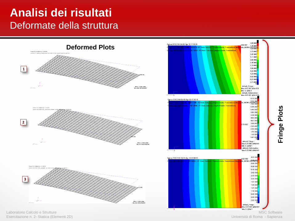
Analisi dei risultati Deformate della struttura
Deformed Plots
Fri
ng
e P
lots
1
2
3

MSC Software
Università di Roma - Sapienza
Laboratorio Calcolo e Strutture
Esercitazione n. 2- Statica (Elementi 2D)
Analisi dei risultati Stato tensionale nella struttura
• Lo stato tensionale viene calcolato nei due punti Z1 e Z2 definiti nella
scheda PSHELL
– Per default:
Z1 = BOTTOM FIBER = -T/2
Z2 = TOP FIBER = T/2
• Se ‘STRESS = ALL stato tensionale calcolato solo al centroide
Tensore delle tensioni Invarianti
Centroide
Corner point
Corner points
Centroide

MSC Software
Università di Roma - Sapienza
Laboratorio Calcolo e Strutture
Esercitazione n. 2- Statica (Elementi 2D)
Analisi dei risultati ‘Fringe Plot’ dello stato tensionale - VonMises
1
3
2

MSC Software
Università di Roma - Sapienza
Laboratorio Calcolo e Strutture
Esercitazione n. 2- Statica (Elementi 2D)
Analisi dei risultati ‘Vector Plot’ dello stato tensionale – Tensioni Principali
1
2
3

MSC Software
Università di Roma - Sapienza
Laboratorio Calcolo e Strutture
Esercitazione n. 2- Statica (Elementi 2D)
ANALYSIS HEALTH CHECKS

MSC Software
Università di Roma - Sapienza
Laboratorio Calcolo e Strutture
Esercitazione n. 2- Statica (Elementi 2D)
• Consistent Units
• Check with Force = Mass * Acceleration
• Element Distortion
• Use your pre-processor to visually check distortion
• Use WARNING messages in .f06 to confirm
Analysis Health Checks Essential ‘Quality Assurance (QA) checks –Pre Analysis

MSC Software
Università di Roma - Sapienza
Laboratorio Calcolo e Strutture
Esercitazione n. 2- Statica (Elementi 2D)
• MSC.Nastran non conosce il concetto di unita’ di misura
• In sostanza opera con i numeri che vengono forniti
• Utilizzare unita’ di misura consistenti
• Attenzione al caso in cui pur operando nell’ambito del S.I. le
lunghezze vengono fornite in mm
• Fornire la densità di massa, altrimenti utilizzare uno dei metodi
suggeriti
Esempio 1: Analisi statica [E]=N/mm2 [L]=mm [P]=N Ku = P [K]=N/mm [u]=mm [Ku]=N
Primo e secondo membro sono in N
Esempio 2: Analisi Dinamica [E]=N/mm2 [L]=mm []=Kg/mm3 [P]=N Ku + Ma = P [K]=N/mm [u]=mm [Ku] = N
[M]=Kg [a]=mm/s2 [P]=N [Ma] = Kg•mm/s2=mN
Numericamente il termine di massa e’ 1000 volte piu’ grande
Soluzione 1: densita’ in [t •mm3] Soluzione 2: PARAM,WTMASS,0.001
Analysis Health Checks Consistent Units - Considerazioni sulle unità di misura

MSC Software
Università di Roma - Sapienza
Laboratorio Calcolo e Strutture
Esercitazione n. 2- Statica (Elementi 2D)
• Element Distortions (cont.)
– Aspect ratio
• Aspect ratio should be less than about 4:1 (much less in regions where
stress levels change rapidly). In cases of nearly-uniaxial stress fields, larger
aspect ratios are acceptable.
– Skew Check
• Quadrilateral elements should be kept as square as possible
a b
a
b
Analysis Health Checks Essential Quality Assurance (QA) checks

MSC Software
Università di Roma - Sapienza
Laboratorio Calcolo e Strutture
Esercitazione n. 2- Statica (Elementi 2D)
• Element Distortions
– Taper Check
– Warp
• Up to ~ 5% is normally acceptable. No real limit, but the element does not
include warpage.
h
ha
WARP = h / [0.5*(D1+D2)]

MSC Software
Università di Roma - Sapienza
Laboratorio Calcolo e Strutture
Esercitazione n. 2- Statica (Elementi 2D)
• Element Distortions checks into Patran
Analysis Health Checks Essential Quality Assurance (QA) checks

MSC Software
Università di Roma - Sapienza
Laboratorio Calcolo e Strutture
Esercitazione n. 2- Statica (Elementi 2D)
• Pre-processors are notorious for generating elements with bad
geometry (aspect ratio, taper, warp, skew, etc)
• In the past, there was a separate message for each element
which did not satisfy the recommendations for MSC Nastran
(this often resulted in pages upon pages of messages which
most users ignored)
• There is now an option (V2001+) which provides user-control of
these messages (so if you want to ignore them, you can disable
their printout – NOT RECOMMENDED)
• This is done by the GEOMCHECK executive control statement
Analysis Health Checks Essential QA checks – Element Geometry checks into MSC Nastran

MSC Software
Università di Roma - Sapienza
Laboratorio Calcolo e Strutture
Esercitazione n. 2- Statica (Elementi 2D)
GEOMCHECK
• Geomcheck specifies geometry check options
– Specifies tolerance values and options for optional finite element
geometry test
Format
test_keyword A keyword associated with the particular element geometry test
tol_value Tolerance value to be used for the specified test
n The minimum number of messages that will produced. The default is 100 messages for each element type.
FATAL Geometry tests that exceed tolerance values produce fatal messages
INFORM Geometry tests that exceed tolerance values produce informative messages (default)
WARN Geometry tests that exceed tolerance values produce warning messages
SUMMARY A summary table of the geometry tests performed is produced. No individual element information messages are output.
NONE None of the optional element geometry tests will be performed
Analysis Health Checks Essential QA checks – GEOMCHECK

MSC Software
Università di Roma - Sapienza
Laboratorio Calcolo e Strutture
Esercitazione n. 2- Statica (Elementi 2D)
• Controls are currently available for following elements only:
Element type Test_keyword: Number of tests
CQUAD4, CQUADR Q4_... 5
CTRIA3, CTRIAR T3_… 2
CTETRA TET_... 4
CHEXA HEX_... 4
CPENTA PEN_... 4
CBEAM BEAM_... 1
CBAR BAR_... 1
Total: 21
• Multiple GEOMCHECK directives may be present.
– Continuations are acceptable.
Analysis Health Checks Essential QA checks – GEOMCHECK (Cont.)

MSC Software
Università di Roma - Sapienza
Laboratorio Calcolo e Strutture
Esercitazione n. 2- Statica (Elementi 2D)
Keyword Value Type Default Comment Q4_SKEW Real ≥ 0.0 30.0 Skew angle in degrees
Q4_TAPER Real ≥ 0.0 0.50 Taper Ratio
Q4_WARP Real ≥ 0.0 0.05 Surface warping factor
Q4_IAMIN Real ≥ 0.0 30.0 Minimum Interior Angle in degrees
Q4_IAMAX Real ≥ 0.0 150.0 Maximum Interior Angle in degrees
T3_SKEW Real ≥ 0.0 10.0 Skew angles in degrees
T3_IAMAX Real ≥ 0.0 160.0 Maximum Interior Angle in degrees
TET_AR Real ≥ 0.0 100.0 Longest edge to shortest edge aspect ratio
TET_EPLR Real ≥ 0.0 0.50 Edge point length ratio
TET_DETJ Real 0.0 | J | minimum value
TET_DETG Real 0.0 | J | minimum value at vertex point
HEX_AR Real ≥ 0.0 100.0 Longest edge to shortest edge aspect ratio
HEX_EPLR Real ≥ 0.0 0.50 Edge point length ratio HEX_DETJ Real 0.0 | J | minimum value
HEX_WARP Real ≥ 0.0 0.707 Face warp coefficient
PEN_AR Real ≥ 0.0 100.0 Longest edge to shortest edge aspect ratio
PEN_EPLR Real ≥ 0.0 0.50 Edge point length ratio
PEN_DETJ Real 0.0 | J | minimum value
PEN_WARP Real ≥ 0.0 0.707 Quadrilateral face warp coefficient
BEAM_OFF Real ≥ 0.0 0.15 CBEAM element offset length ratio
BAR_OFF Real ≥ 0.0 0.15 CBEAM element offset length ratio
Analysis Health Checks Essential QA checks – GEOMCHECK (Cont.)

MSC Software
Università di Roma - Sapienza
Laboratorio Calcolo e Strutture
Esercitazione n. 2- Statica (Elementi 2D)
• Examples: 1. Set the tolerance for the CQUAD4 element skew angle test to
15.0 degrees and limit the messages to 50.
GEOMCHECK Q4_SKEW=15.0,MSGLIMIT=50
2. Limit messages to 500 for each element type
GEOMCHECK MSGLIMIT = 500
3. Set the message type to fatal for CQUAD4 element taper tests.
GEOMCHECK Q4_TAPER,MSGTYPE=FATAL
4. Request summary table output only using default tolerance values.
GEOMCHECK SUMMARY
Analysis Health Checks Essential QA checks – GEOMCHECK (Cont.)

MSC Software
Università di Roma - Sapienza
Laboratorio Calcolo e Strutture
Esercitazione n. 2- Statica (Elementi 2D)
Analysis Health Checks Essential QA checks – GEOMCHECK (Cont.)

MSC Software
Università di Roma - Sapienza
Laboratorio Calcolo e Strutture
Esercitazione n. 2- Statica (Elementi 2D)
• Q4_Skew Check
Skew test: Skew angle for the
quadrilateral element is defined
to be the angle between the lines
that joins midpoints of opposite
sides of the quadrilateral.
Quadrilateral elements should
be kept as square as possible.
This angle is not 90 degrees
for any skew.
Desired value : α ≥ 60.
Analysis Health Checks Essential QA checks – GEOMCHECK (Cont.)
(default value)
• Q4_Taper Check
Taper test: Taper ratio for the
quadrilateral element is defined to
be the ratio of the area of the
triangle formed at each corner grid
point to one half the area of the
quadrilateral. The largest of the four
ratios is compared against the
tolerance value.
= A/4

MSC Software
Università di Roma - Sapienza
Laboratorio Calcolo e Strutture
Esercitazione n. 2- Statica (Elementi 2D)
• Q4_WARP Check
Warp test: Surface warping factor
for quadrilateral is defined to be the
distance of the corner points of the
element to the mean plane of the
grid points divided by the average
of the element diagonal lengths. Up to ~ 5% is normally acceptable. No
real limit, but the element does not
include warpage. For flat elements (all
grid point lie in a plane), this factor is
zero. Q4_WARP = H / [ (D1+D2)/2 ]
H D1
D2
Default value: Q4_WARP = 0.05
• Q4_IAMIN and Q4_IAMA
T3_SKEW and T3_IAMAX
Interior Angle test: Interior angles
are defined to be the angles formed
by the edges that meet at the
corner node on an element. There
are four for quadrilateral shapes
and three for triangular shapes. Skew angle for the triangular element is
defined to be the smallest angle at any
of the three vertices. T3_SKEW will be
changed to T3_IAMIN
Q4_IAMIN
Q4_IAMAX
T3_SKEW
T3_IAMAX
Default values:
Q4_IAMIN = 30o
Q4_IAMAX= 150o
Default values:
T3_SKEW = 10o
T3_IAMAX= 160o
Analysis Health Checks Essential QA checks – GEOMCHECK (Cont.)
MSC Software
Università di Roma - Sapienza
Laboratorio Calcolo e Strutture
Esercitazione n. 2- Statica (Elementi 2D)
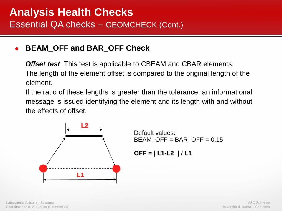
● BEAM_OFF and BAR_OFF Check
Offset test: This test is applicable to CBEAM and CBAR elements.
The length of the element offset is compared to the original length of the
element.
If the ratio of these lengths is greater than the tolerance, an informational
message is issued identifying the element and its length with and without
the effects of offset.
Default values: BEAM_OFF = BAR_OFF = 0.15 OFF = | L1-L2 | / L1
L1
L2
● ●
Analysis Health Checks Essential QA checks – GEOMCHECK (Cont.)

S5-56 NAS101A, Section 5, March 2012
Copyright 2012 MSC.Software Corporation
45o
80 QUAD elements
• Example:
GEOMCHECK Q4_SKEW=60., MSGLIMIT=5
• A SKEW angle of 90. degree is the ideal
value.
• The test will generate a message for any
value smaller than 60. degree.
• A Maximum of only 5 messages will be
generated.
• The default MSGTYPE is
MSGTYPE=INFORM,
• xxxx is the indicator for this type.
• The run will not be terminated
independently if this test fails.
Analysis Health Checks Essential QA checks – Element geometry check example

S5-57 NAS101A, Section 5, March 2012
Copyright 2012 MSC.Software Corporation
M O D E L S U M M A R Y
NUMBER OF GRID POINTS = 102
NUMBER OF CQUAD4 ELEMENTS = 80
*** USER INFORMATION MESSAGE 7555 (GMTSTD)
FINITE ELEMENT GEOMETRY CHECK RESULTS EXCEED TOLERANCE LEVELS FOR THE FOLLOWING ELEMENTS. METRIC VALUES THAT EXCEED
TEST TOLERANCE LIMITS ARE IDENTIFIED BY ONE OF THE FOLLOWING FLAGS PLACED TO THE RIGHT OF THE METRIC VALUE.
"xxxx" FOR TEST RESULTS EXCEEDING TOLERANCES. INFORMATIONAL ONLY. PROBLEM SOLUTION CONTINUES. (DEFAULT FLAG)
"xxxx" FOR TEST RESULTS EXCEEDING TOLERANCES. INFORMATIONAL ONLY. PROBLEM SOLUTION CONTINUES.
"WARN" FOR TEST RESULTS EXCEEDING TOLERANCES. INFORMATIONAL ONLY. PROBLEM SOLUTION CONTINUES.
"FAIL" FOR TEST RESULTS EXCEEDING TOLERANCES. SEVERE ERROR. PROBLEM SOLUTION TERMINATES.
USER ACTION: USE THE GEOMCHECK (EXECUTIVE CONTROL STATEMENT) KEYWORD=VALUE TO CHANGE TOLERANCE VALUES IF DESIRED.
A MAXIMUM OF 5 SKEW ANGLE (SA) TOLERANCE LIMIT VIOLATIONS WILL BE IDENTIFIED BY THE FLAG "xxxx"
PLACED AFTER THE VALUE METRIC FOR THE TEST.
A MAXIMUM OF 100 MIN INT. ANGLE (IA) TOLERANCE LIMIT VIOLATIONS WILL BE IDENTIFIED BY THE FLAG "xxxx"
PLACED AFTER THE VALUE METRIC FOR THE TEST.
A MAXIMUM OF 100 MAX INT. ANGLE (IA) TOLERANCE LIMIT VIOLATIONS WILL BE IDENTIFIED BY THE FLAG "xxxx"
PLACED AFTER THE VALUE METRIC FOR THE TEST.
A MAXIMUM OF 100 WARPING FACTOR (WF) TOLERANCE LIMIT VIOLATIONS WILL BE IDENTIFIED BY THE FLAG "xxxx"
PLACED AFTER THE VALUE METRIC FOR THE TEST.
A MAXIMUM OF 100 TAPER RATIO (TR) TOLERANCE LIMIT VIOLATIONS WILL BE IDENTIFIED BY THE FLAG "xxxx"
PLACED AFTER THE VALUE METRIC FOR THE TEST.
USER INFORMATION: THE MAXIMUM MESSAGE COUNT FOR ANY ONE ELEMENT ERROR TEST COULD BE EXCEEDED BY THE
CUMULATIVE EFFECT OF ALL THE MESSAGES GENERATED FOR ALL OF THE DIFFERENT TESTS PERFORMED.
GEOMCHECK Q4_SKEW=60.,MSGLIMIT=5
Maximum 5 message for the Q4_SKEW test only.
Maximum 100 messages (default
number) for the other QUAD tests.
Explanation of possible message flags.
The user specifies which type of flag will
be used with MSCTYPE option.
Analysis Health Checks Essential QA checks – Element geometry check example

S5-58 NAS101A, Section 5, March 2012
Copyright 2012 MSC.Software Corporation
1 MSC.NASTRAN JOB CREATED ON 28-JUL-05 AT 11:18:00 JULY 28, 2005 MSC.NASTRAN 9/23/04 PAGE 4
0
TOLERANCE LIMITS ARE: SA = 60.00, IA(MIN) = 30.00, IA(MAX) = 150.00, WF = 0.05, TR = 0.50 (FLAG = LIMIT VIOLATED)
ELEMENT TYPE ID SKEW ANGLE MIN INT. ANGLE MAX INT. ANGLE WARPING FACTOR TAPER RATIO
QUAD4 1 45.00 xxxx 45.00 135.00 0.00 0.00
QUAD4 2 45.00 xxxx 45.00 135.00 0.00 0.00
QUAD4 3 45.00 xxxx 45.00 135.00 0.00 0.00
QUAD4 4 45.00 xxxx 45.00 135.00 0.00 0.00
QUAD4 5 45.00 xxxx 45.00 135.00 0.00 0.00
1 MSC.NASTRAN JOB CREATED ON 28-JUL-05 AT 11:18:00 JULY 28, 2005 MSC.NASTRAN 9/23/04 PAGE 5
0
E L E M E N T G E O M E T R Y T E S T R E S U L T S S U M M A R Y
TOTAL NUMBER OF TIMES TOLERANCES WERE EXCEEDED
ASPECT/ MINIMUM MAXIMUM SURFACE/FACE EDGE POINT JACOBIAN
ELEMENT TYPE SKEW ANGLE TAPER RATIO INTER. ANGLE INTER. ANGLE WARP FACTOR OFFSET RATIO LENGTH RATIO DETERMINANT
QUAD4 80 0 0 0 0 N/A N/A N/A
N/A IN THE ABOVE TABLE INDICATES TESTS THAT ARE NOT APPLICABLE TO THE ELEMENT TYPE AND WERE NOT PERFORMED.
FOR ALL ELEMENTS WHERE GEOMETRY TEST RESULTS HAVE EXCEEDED TOLERANCES,
QUAD4 ELEMENT ID 1 PRODUCED SMALLEST SKEW ANGLE OF 45.00 (TOLERANCE = 60.00).
GEOMCHECK Q4_SKEW=60.,MSGLIMIT=5,MSGTYPE=INFORM
The run will not be terminated if this test fails.
Analysis Health Checks Essential QA checks – Element geometry check example

S5-59 NAS101A, Section 5, March 2012
Copyright 2012 MSC.Software Corporation
1 MSC.NASTRAN JOB CREATED ON 28-JUL-05 AT 11:18:00 JULY 28, 2005 MSC.NASTRAN 9/23/04 PAGE 4
0
TOLERANCE LIMITS ARE: SA = 60.00, IA(MIN) = 30.00, IA(MAX) = 150.00, WF = 0.05, TR = 0.50 (FLAG = LIMIT VIOLATED)
ELEMENT TYPE ID SKEW ANGLE MIN INT. ANGLE MAX INT. ANGLE WARPING FACTOR TAPER RATIO
QUAD4 1 45.00 WARN 45.00 135.00 0.00 0.00
QUAD4 2 45.00 WARN 45.00 135.00 0.00 0.00
QUAD4 3 45.00 WARN 45.00 135.00 0.00 0.00
QUAD4 4 45.00 WARN 45.00 135.00 0.00 0.00
QUAD4 5 45.00 WARN 45.00 135.00 0.00 0.00
1 MSC.NASTRAN JOB CREATED ON 28-JUL-05 AT 11:18:00 JULY 28, 2005 MSC.NASTRAN 9/23/04 PAGE 5
0
E L E M E N T G E O M E T R Y T E S T R E S U L T S S U M M A R Y
TOTAL NUMBER OF TIMES TOLERANCES WERE EXCEEDED
ASPECT/ MINIMUM MAXIMUM SURFACE/FACE EDGE POINT JACOBIAN
ELEMENT TYPE SKEW ANGLE TAPER RATIO INTER. ANGLE INTER. ANGLE WARP FACTOR OFFSET RATIO LENGTH RATIO DETERMINANT
QUAD4 80 0 0 0 0 N/A N/A N/A
N/A IN THE ABOVE TABLE INDICATES TESTS THAT ARE NOT APPLICABLE TO THE ELEMENT TYPE AND WERE NOT PERFORMED.
FOR ALL ELEMENTS WHERE GEOMETRY TEST RESULTS HAVE EXCEEDED TOLERANCES,
QUAD4 ELEMENT ID 1 PRODUCED SMALLEST SKEW ANGLE OF 45.00 (TOLERANCE = 60.00).
GEOMCHECK Q4_SKEW=60.,MSGLIMIT=5,MSGTYPE=WARN
The run will not be terminated if this test fails.
Analysis Health Checks Essential QA checks – Element geometry check example

S5-60 NAS101A, Section 5, March 2012
Copyright 2012 MSC.Software Corporation
1 MSC.NASTRAN JOB CREATED ON 28-JUL-05 AT 11:18:00 JULY 28, 2005 MSC.NASTRAN 9/23/04 PAGE 4
0
TOLERANCE LIMITS ARE: SA = 60.00, IA(MIN) = 30.00, IA(MAX) = 150.00, WF = 0.05, TR = 0.50 (FLAG = LIMIT VIOLATED)
ELEMENT TYPE ID SKEW ANGLE MIN INT. ANGLE MAX INT. ANGLE WARPING FACTOR TAPER RATIO
QUAD4 1 45.00 FAIL 45.00 135.00 0.00 0.00
QUAD4 2 45.00 FAIL 45.00 135.00 0.00 0.00
QUAD4 3 45.00 FAIL 45.00 135.00 0.00 0.00
QUAD4 4 45.00 FAIL 45.00 135.00 0.00 0.00
QUAD4 5 45.00 FAIL 45.00 135.00 0.00 0.00
1 MSC.NASTRAN JOB CREATED ON 28-JUL-05 AT 11:18:00 JULY 28, 2005 MSC.NASTRAN 9/23/04 PAGE 5
0
E L E M E N T G E O M E T R Y T E S T R E S U L T S S U M M A R Y
TOTAL NUMBER OF TIMES TOLERANCES WERE EXCEEDED
ASPECT/ MINIMUM MAXIMUM SURFACE/FACE EDGE POINT JACOBIAN
ELEMENT TYPE SKEW ANGLE TAPER RATIO INTER. ANGLE INTER. ANGLE WARP FACTOR OFFSET RATIO LENGTH RATIO DETERMINANT
QUAD4 80 0 0 0 0 N/A N/A N/A
N/A IN THE ABOVE TABLE INDICATES TESTS THAT ARE NOT APPLICABLE TO THE ELEMENT TYPE AND WERE NOT PERFORMED.
FOR ALL ELEMENTS WHERE GEOMETRY TEST RESULTS HAVE EXCEEDED TOLERANCES,
QUAD4 ELEMENT ID 1 PRODUCED SMALLEST SKEW ANGLE OF 45.00 (TOLERANCE = 60.00).
1 MSC.NASTRAN JOB CREATED ON 28-JUL-05 AT 11:18:00 JULY 28, 2005 MSC.NASTRAN 9/23/04 PAGE 6
0
*** USER FATAL MESSAGE 7555 (EMGPRO)
EMG MODULE TERMINATING DUE TO SEVERE FAILURE OF ELEMENT GEOMETRY CHECK TESTS. THE ELEMENT TYPES, ELEMENT IDS AND FAILING
TESTS ARE IDENTIFIED ON PREVIOUS PAGES WITH THE FLAG "FAIL" PLACED AFTER THE VALUE METRIC OF THE TEST THAT FAILED.
^^^ USER WARNING MESSAGE 9031 (ERRPH1)
^^^ NOGO ENCOUNTERED IN SUBDMAP SEMG
GEOMCHECK Q4_SKEW=60.,MSGLIMIT=5,MSGTYPE=FATAL
The run will be terminated if this test fails.
Analysis Health Checks Essential QA checks – Element geometry check example

MSC Software
Università di Roma - Sapienza
Laboratorio Calcolo e Strutture
Esercitazione n. 2- Statica (Elementi 2D)
• Epsilon Value
• Applied Load Summation
• Reaction Summation
• Strain Energy Values
• Peak Deflections
Analysis Health Checks Essential QA checks – Post Analysis

MSC Software
Università di Roma - Sapienza
Laboratorio Calcolo e Strutture
Esercitazione n. 2- Statica (Elementi 2D)
Analysis Health Checks Essential QA checks – Post Analysis: Epsilon Value
• If 10-6 , or greater, it could be a
sign of ill-conditioning.
• For your type of Structure,
Idealization and Analysis
– Establish typical values for Epsilon
– Establish an agreed threshold
*** USER INFORMATION MESSAGE 5293 (SSG3A)
FOR DATA BLOCK KLL
LOAD SEQ. NO. EPSILON EXTERNAL WORK EPSILONS LARGER THAN 0.001 ARE FLAGGED WITH ASTERISKS
1 -1.3760919E-13 3.6560133E+04

MSC Software
Università di Roma - Sapienza
Laboratorio Calcolo e Strutture
Esercitazione n. 2- Statica (Elementi 2D)
• Particularly Important for:
– Inertia Loading
– Complex Pressure Loading
– Complex Distributed Loading
Analysis Health Checks Essential QA checks – Post Analysis: Applied Load Summation
0 RESULTANTS ABOUT ORIGIN OF SUPERELEMENT BASIC COORDINATE SYSTEM IN SUPERELEMENT BASIC SYSTEM COORDINATES.
0 OLOAD RESULTANT
SUBCASE/ LOAD
DAREA ID TYPE T1 T2 T3 R1 R2 R3
0 1 FX -3.900000E+03 ---- ---- ---- 0.000000E+00 3.744000E+05
FY ---- -4.500000E+03 ---- 0.000000E+00 ---- -1.296000E+06
FZ ---- ---- 0.000000E+00 0.000000E+00 0.000000E+00 ----
MX ---- ---- ---- 0.000000E+00 ---- ----
MY ---- ---- ---- ---- 0.000000E+00 ----
MZ ---- ---- ---- ---- ---- 0.000000E+00
TOTALS -3.900000E+03 -4.500000E+03 0.000000E+00 0.000000E+00 0.000000E+00 -9.216000E+05
0 20 FX 0.000000E+00 ---- ---- ---- 0.000000E+00 0.000000E+00
FY ---- -1.818989E-12 ---- 0.000000E+00 ---- 9.313226E-10
FZ ---- ---- 0.000000E+00 0.000000E+00 0.000000E+00 ----
MX ---- ---- ---- 0.000000E+00 ---- ----
MY ---- ---- ---- ---- 0.000000E+00 ----
MZ ---- ---- ---- ---- ---- 0.000000E+00
TOTALS 0.000000E+00 -1.818989E-12 0.000000E+00 0.000000E+00 0.000000E+00 9.313226E-10
0 30 FX 0.000000E+00 ---- ---- ---- 0.000000E+00 0.000000E+00
FY ---- -2.123938E+03 ---- 0.000000E+00 ---- -6.116941E+05
FZ ---- ---- 0.000000E+00 0.000000E+00 0.000000E+00 ----
MX ---- ---- ---- 0.000000E+00 ---- ----
MY ---- ---- ---- ---- 0.000000E+00 ----
MZ ---- ---- ---- ---- ---- 0.000000E+00
TOTALS 0.000000E+00 -2.123938E+03 0.000000E+00 0.000000E+00 0.000000E+00 -6.116941E+05
MSC Software
Università di Roma - Sapienza
Laboratorio Calcolo e Strutture
Esercitazione n. 2- Statica (Elementi 2D)
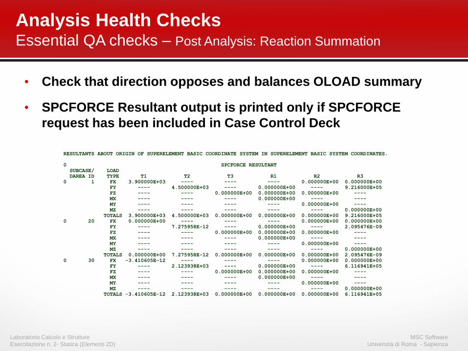
• Check that direction opposes and balances OLOAD summary
• SPCFORCE Resultant output is printed only if SPCFORCE
request has been included in Case Control Deck
Analysis Health Checks Essential QA checks – Post Analysis: Reaction Summation
RESULTANTS ABOUT ORIGIN OF SUPERELEMENT BASIC COORDINATE SYSTEM IN SUPERELEMENT BASIC SYSTEM COORDINATES.
0 SPCFORCE RESULTANT
SUBCASE/ LOAD
DAREA ID TYPE T1 T2 T3 R1 R2 R3
0 1 FX 3.900000E+03 ---- ---- ---- 0.000000E+00 0.000000E+00
FY ---- 4.500000E+03 ---- 0.000000E+00 ---- 9.216000E+05
FZ ---- ---- 0.000000E+00 0.000000E+00 0.000000E+00 ----
MX ---- ---- ---- 0.000000E+00 ---- ----
MY ---- ---- ---- ---- 0.000000E+00 ----
MZ ---- ---- ---- ---- ---- 0.000000E+00
TOTALS 3.900000E+03 4.500000E+03 0.000000E+00 0.000000E+00 0.000000E+00 9.216000E+05
0 20 FX 0.000000E+00 ---- ---- ---- 0.000000E+00 0.000000E+00
FY ---- 7.275958E-12 ---- 0.000000E+00 ---- 2.095476E-09
FZ ---- ---- 0.000000E+00 0.000000E+00 0.000000E+00 ----
MX ---- ---- ---- 0.000000E+00 ---- ----
MY ---- ---- ---- ---- 0.000000E+00 ----
MZ ---- ---- ---- ---- ---- 0.000000E+00
TOTALS 0.000000E+00 7.275958E-12 0.000000E+00 0.000000E+00 0.000000E+00 2.095476E-09
0 30 FX -3.410605E-12 ---- ---- ---- 0.000000E+00 0.000000E+00
FY ---- 2.123938E+03 ---- 0.000000E+00 ---- 6.116941E+05
FZ ---- ---- 0.000000E+00 0.000000E+00 0.000000E+00 ----
MX ---- ---- ---- 0.000000E+00 ---- ----
MY ---- ---- ---- ---- 0.000000E+00 ----
MZ ---- ---- ---- ---- ---- 0.000000E+00
TOTALS -3.410605E-12 2.123938E+03 0.000000E+00 0.000000E+00 0.000000E+00 6.116941E+05

MSC Software
Università di Roma - Sapienza
Laboratorio Calcolo e Strutture
Esercitazione n. 2- Statica (Elementi 2D)
• Equilibrium check is probably one of
the most important checks in static
analysis
S F = 0 S M = 0
– Previously, one can obtain OLOAD,
SPCFORCE, and MPCFORCE resultants
and manually add them up for equilibrium
check
– New EQUILIBRIUM Case Control command
available to request equilibrium output
• Available only for static analysis
Analysis Health Checks Essential QA checks – Post Analysis: Equilibrium Ckecks

MSC Software
Università di Roma - Sapienza
Laboratorio Calcolo e Strutture
Esercitazione n. 2- Statica (Elementi 2D)
• Set PARAM,PRTMAXIM,YES to output this
• The GRID ID is not included and can be different for each DOF
0
0 MAXIMUM DISPLACEMENTS
0 T1 T2 T3 R1 R2 R3
0 1 3.0938861E-07 4.1483727E-08 3.6560131E+01 7.2180829E+00 5.6827263E+01 0.0000000E+00
Value !!!
Work = ( approx) ½ OLOAD * Peak Deflection = ( 2e3 * 36.5 *.5 = 36.5e3 )
Analysis Health Checks Essential QA checks – Post Analysis: Peak Deflections & Strain Energy
*** USER INFORMATION MESSAGE 5293 (SSG3A)
FOR DATA BLOCK KLL
LOAD SEQ. NO. EPSILON EXTERNAL WORK EPSILONS LARGER THAN 0.001 ARE FLAGGED WITH ASTERISKS
1 -1.3760919E-13 3.6560133E+04
Work = ½ Total Force * Total Deflection
= ( approx) ½ OLOAD * Peak Deflection
( if peak deflection is near mean line of loading action)

MSC Software
Università di Roma - Sapienza
Laboratorio Calcolo e Strutture
Esercitazione n. 2- Statica (Elementi 2D)
GOOD MODELING PRACTICE

MSC Software
Università di Roma - Sapienza
Laboratorio Calcolo e Strutture
Esercitazione n. 2- Statica (Elementi 2D)
• Mesh Density – fit for purpose
• Mesh Quality – fit for purpose
• Loading Boundary Conditions
• Displacement Boundary Conditions
Good Modeling Practice Essentials

MSC Software
Università di Roma - Sapienza
Laboratorio Calcolo e Strutture
Esercitazione n. 2- Statica (Elementi 2D)
• Fit for purpose
– Consider the stress gradient as parameter
Good Modeling Practice Essentials – Mesh Density

MSC Software
Università di Roma - Sapienza
Laboratorio Calcolo e Strutture
Esercitazione n. 2- Statica (Elementi 2D)
• Fit for purpose
– Generate mesh where elements are as regular as possible
Good Modeling Practice Essentials – Mesh Quality

MSC Software
Università di Roma - Sapienza
Laboratorio Calcolo e Strutture
Esercitazione n. 2- Statica (Elementi 2D)
Poor stress distribution locally Good stress distribution locally
Good Modeling Practice Essentials – Loading Boundary Conditions
• Single Boundary Conditions?
• Single Boundary Conditions?

MSC Software
Università di Roma - Sapienza
Laboratorio Calcolo e Strutture
Esercitazione n. 2- Statica (Elementi 2D)
• Wrongly defining Output Coordinate Systems at SPCs, MPCs,
RIGID Elements, etc. can wreck a model.
• Over-constraining a model can give rise to Poisson contraction
stresses that distort the true stress field.
• A single nodal constraint (or force) produces a singularity in the
stress field - stress results at this point are likely to be erroneous.
• A special technique called inertia relief is available to perform
quasi-static analysis on unconstrained (free) structures under
uniform (i.e. zero or constant) acceleration.
Good Modeling Practice Essentials – Displacement Constraint Considerations