Embed Size (px)
Citation preview

© 2014 Littelfuse, Inc.Specifications are subject to change without notice. Revised: 05/23/14
Varistor ProductsRadial Lead Varistors > LA Series
LA S
erie
s
Description
The LA Series of transient voltage surge suppressors are radial leaded varistors (MOVs) that are designed to be operated continuously across AC power lines. These UL recognized varistors require very little mounting space, and are offered in various standard lead form options.
The LA Series varistors are available in four model sizes: 7mm, 10mm, 14mm and 20mm; and have a VM(AC)RMS voltage range from 130V to 1000V, and an energy absorption capability up to 360J. Some LA Series model numbers are available with clamping voltage selections, designated by a model number suffix of either A or B. The 'A' selection is the standard model; the 'B' selection provides a lower clamping voltage.See LA Series Device Ratings and Specifications Table for part number and brand information.
Features
• Lead–free,Halogen-Free and RoHS compliant.
• Energyabsorptioncapability (WTM) up to 360J
• Wideoperating voltage range
VM(AC)RMS 130V to 1000V
• Noderatingupto85ºC ambient
• Availableintapeandreel or bulk pack
Agency Approvals
Absolute Maximum Ratings•Forratingsofindividualmembersofaseries,seeDeviceRatingsandSpecificationschart
Agency Agency File Number
E320116, E135010
116895
LR91788
42201-006
Continuous LA Series Units
Steady State Applied Voltage:AC Voltage Range (VM(AC)RMS) 130 to 1000 V
DC Voltage Range (VM(DC)) 175 to 1200 V
Transients:Peak Pulse Current (ITM)
For 8/20µs Current Wave (See Figure 2) 1200 to 6500 A
Single Pulse Energy Range
For 10/1000µs Current Wave (WTM) 11 to 360 J
Operating Ambient Temperature Range (TA) -55 to +85 OC
Storage Temperature Range (TSTG) -55 to +125 OC
Temperature Coefficient (aV) of Clamping Voltage (VC) at Specified Test Current <0.01 %/OC
Hi-Pot Encapsulation (COATING Isolation Voltage Capability)(Dielectric must withstand indicated DC voltage for one minute per MIL-STD 202, Method 301) 2500 V
COATING Insulation Resistance 1000 MΩ
CAUTION: Stresses above those listed in “Absolute Maximum Ratings” may cause permanent damage to the device. This is a stress only rating and operation of the device at these or any other conditions above those indicated in the operational sections of this specification is not implied.
LA Varistor Series RoHS
© 2014 Littelfuse, Inc.Specifications are subject to change without notice.
Revised: 05/23/14
Varistor ProductsRadial Lead Varistors > LA Series
LA Series Ratings & Specifications
Part Number Branding
Model Size Disc Dia.
(mm)
Maximum Rating (85°C) Specifications (25°C)Continuous Transient Varistor
Voltage at 1mA
DC Test Current
Maximum Clamping Voltage
8 x 20 µs
Typical Capaci-tance f =
1MHzVRMS VDC
Energy 10 x 1000µs
Peak Current 8
x 20µs
VM(AC) VM(DC) WTM ITM VNOM Min
VNOM Max VC IPK C
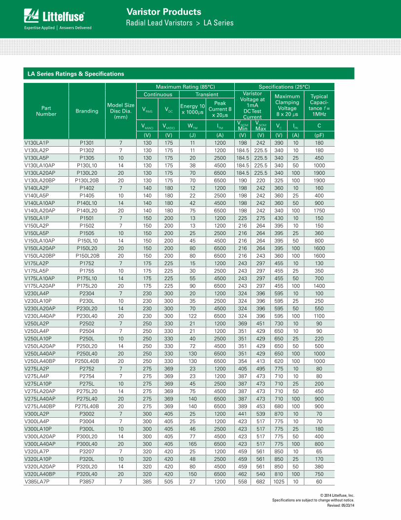
(V) (V) (J) (A) (V) (V) (V) (A) (pF)V130LA1P P1301 7 130 175 11 1200 198 242 390 10 180V130LA2P P1302 7 130 175 11 1200 184.5 225.5 340 10 180V130LA5P P1305 10 130 175 20 2500 184.5 225.5 340 25 450V130LA10AP P130L10 14 130 175 38 4500 184.5 225.5 340 50 1000V130LA20AP P130L20 20 130 175 70 6500 184.5 225.5 340 100 1900V130LA20BP P130L20B 20 130 175 70 6500 190 220 325 100 1900V140LA2P P1402 7 140 180 12 1200 198 242 360 10 160V140LA5P P1405 10 140 180 22 2500 198 242 360 25 400V140LA10AP P140L10 14 140 180 42 4500 198 242 360 50 900V140LA20AP P140L20 20 140 180 75 6500 198 242 340 100 1750V150LA1P P1501 7 150 200 13 1200 225 275 430 10 150V150LA2P P1502 7 150 200 13 1200 216 264 395 10 150V150LA5P P1505 10 150 200 25 2500 216 264 395 25 360V150LA10AP P150L10 14 150 200 45 4500 216 264 395 50 800V150LA20AP P150L20 20 150 200 80 6500 216 264 395 100 1600V150LA20BP P150L20B 20 150 200 80 6500 216 243 360 100 1600V175LA2P P1752 7 175 225 15 1200 243 297 455 10 130V175LA5P P1755 10 175 225 30 2500 243 297 455 25 350V175LA10AP P175L10 14 175 225 55 4500 243 297 455 50 700V175LA20AP P175L20 20 175 225 90 6500 243 297 455 100 1400V230LA4P P2304 7 230 300 20 1200 324 396 595 10 100V230LA10P P230L 10 230 300 35 2500 324 396 595 25 250V230LA20AP P230L20 14 230 300 70 4500 324 396 595 50 550V230LA40AP P230L40 20 230 300 122 6500 324 396 595 100 1100V250LA2P P2502 7 250 330 21 1200 369 451 730 10 90V250LA4P P2504 7 250 330 21 1200 351 429 650 10 90V250LA10P P250L 10 250 330 40 2500 351 429 650 25 220V250LA20AP P250L20 14 250 330 72 4500 351 429 650 50 500V250LA40AP P250L40 20 250 330 130 6500 351 429 650 100 1000V250LA40BP P250L40B 20 250 330 130 6500 354 413 620 100 1000V275LA2P P2752 7 275 369 23 1200 405 495 775 10 80V275LA4P P2754 7 275 369 23 1200 387 473 710 10 80V275LA10P P275L 10 275 369 45 2500 387 473 710 25 200V275LA20AP P275L20 14 275 369 75 4500 387 473 710 50 450V275LA40AP P275L40 20 275 369 140 6500 387 473 710 100 900V275LA40BP P275L40B 20 275 369 140 6500 389 453 680 100 900V300LA2P P3002 7 300 405 25 1200 441 539 870 10 70V300LA4P P3004 7 300 405 25 1200 423 517 775 10 70V300LA10P P300L 10 300 405 46 2500 423 517 775 25 180V300LA20AP P300L20 14 300 405 77 4500 423 517 775 50 400V300LA40AP P300L40 20 300 405 165 6500 423 517 775 100 800V320LA7P P3207 7 320 420 25 1200 459 561 850 10 65V320LA10P P320L 10 320 420 48 2500 459 561 850 25 170V320LA20AP P320L20 14 320 420 80 4500 459 561 850 50 380V320LA40BP P320L40 20 320 420 150 6500 462 540 810 100 750V385LA7P P3857 7 385 505 27 1200 558 682 1025 10 60

© 2014 Littelfuse, Inc.Specifications are subject to change without notice. Revised: 05/23/14
Varistor ProductsRadial Lead Varistors > LA Series
LA S
erie
s
Part Number Branding
Model Size Disc Dia.
(mm)
Maximum Rating (85°C) Specifications (25°C)Continuous Transient Varistor
Voltage at 1mA
DC Test Current
Maximum Clamping Voltage
8 x 20 µs
Typical Capaci-tance f =
1MHzVRMS VDC
Energy 10 x 1000µs
Peak Current 8
x 20µs
VM(AC) VM(DC) WTM ITM VNOM Min
VNOM Max VC IPK C
(V) (V) (J) (A) (V) (V) (V) (A) (pF)V385LA10P P385L 10 385 505 51 2500 558 682 1025 25 160V385LA20AP P385L20 14 385 505 85 4500 558 682 1025 50 360V385LA40BP P385L40 20 385 505 160 6500 558 682 1025 100 700V420LA7P P4207 7 420 560 30 1200 612 748 1120 10 55V420LA10P P420L 10 420 560 55 2500 612 748 1120 25 140V420LA20AP P420L20 14 420 560 90 4500 612 748 1120 50 300V420LA40BP P420L40 20 420 560 160 6500 610 720 1060 100 600V460LA7P P4607 7 460 615 37 1200 643.5 786.5 1190 10 55V460LA10P P460L 10 460 615 56 2500 643.5 786.5 1190 25 120V460LA20AP P460L20 14 460 615 100 4500 643.5 786.5 1190 50 280V460LA40BP P460L40 20 460 615 170 6500 643.5 755.5 1110 100 560V480LA7P P4807 7 480 640 35 1200 675 825 1240 10 50V480LA10P P480L 10 480 640 60 2500 675 825 1240 25 120V480LA40AP P480L40 14 480 640 105 4500 675 825 1240 50 270V480LA80BP P480L80 20 480 640 180 6500 675 790 1160 100 550V510LA10P P510L 10 510 675 63 2500 738 902 1350 25 100V510LA40AP P510L40 14 510 675 110 4500 738 902 1350 50 250V510LA80BP P510L80 20 510 675 190 6500 738 860 1280 100 500V575LA10P P575L 10 575 730 65 2500 819 1001 1500 25 90V575LA40AP P575L40 14 575 730 120 4500 819 1001 1500 50 220V575LA80BP P575L80 20 575 730 220 6500 819 960 1410 100 450V625LA10P P625L 10 625 825 67 2500 900 1100 1650 25 80V625LA40AP P625L40 14 625 825 125 4500 900 1100 1650 50 210V625LA80BP P625L80 20 625 825 230 6500 900 1100 1650 100 425V680LA10P P680L 10 680 875 75 2500 990 1210 1875 25 65V680LA80AP P680L80 14 680 875 145 4500 990 1210 1875 50 190
V680LA100BP P680L100 20 680 875 260 6500 990 1130 1700 100 380
V660LA10P P660L 10 660 850 70 2500 972 1188 1820 25 70V660LA50AP P660L50 14 660 850 140 4500 972 1188 1820 50 200V660LA100BP P660L100 20 660 850 250 6500 940 1100 1650 100 400V1000LA80AP P1000L8 14 1000 1200 220 4500 1500 1800 2700 50 130V1000LA160BP P1000L16 20 1000 1200 360 6500 1425 1600 2420 100 250
LA Series Ratings & Specifications (Continued...)
NOTE: Average power dissipation of transients not to exceed 0.25W, 0.4W, 0.6W or 1W for model sizes 7mm, 10mm, 14mm and 20mm, respectively.
Phenolic Coating Option -- LA Series Varistors for Hi-Temperature Operating Conditions:
• Phenolic–coatedLASeriesdevicesareavailablewithimprovedmaximumoperatingmaximumtemperature125°C.
• Thesedevicesalsohaveimprovedtemperaturecyclingperformancecapability.
• RatingsandSpecificationsareasperstandardLASeriesexceptHi–PotEncapsulation(IsolationVoltageCapability)=500V.
• ThesedevicesarenotUL,CSA,VDEorCECCcertified.
• Toorder:addX1347toendofpartnumber(e.g.V230LA20APX1347)
• Productmarking:LF 9
P230P20YYWW Phenolic Coated
OptionIdentifier
Lead-Free,Halogen-Free
& RoHS CompliantIndicator
© 2014 Littelfuse, Inc.Specifications are subject to change without notice.
Revised: 05/23/14
Varistor ProductsRadial Lead Varistors > LA Series
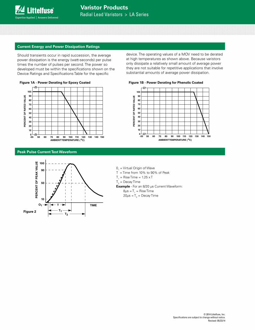
Should transients occur in rapid succession, the average power dissipation is the energy (watt-seconds) per pulse times the number of pulses per second. The power so developed must be within the specifications shown on the Device Ratings and Specifications Table for the specific
Current Energy and Power Dissipation Ratings
Peak Pulse Current Test Waveform
FIGURE 2. PEAK PULSE CURRENT TEST WAVEFORM
100
90
50
10
O1 T
T1T2
TIME
PE
RC
EN
T O
F P
EA
K V
AL
UE
O1 = Virtual Origin of WaveT = Time From 10% to 90% of Peak
T1 = Virtual Front time = 1.25 • tT2 = Virtual Time to Half Value (Impulse Duration)
Example: For an 8/20µs Current Waveform:8 s = T1 = Virtual Front Time
20 s = T2 = Virtual Time to Half Value
01 = Virtual Origin of WaveT = Time from 10% to 90% of PeakT1 = Rise Time = 1.25 x TT2 = Decay TimeExample - For an 8/20 µs Current Waveform:
8µs = T1 = Rise Time20µs = T2 = Decay Time
100
90
80
70
60
50
40
30
20
10
0-55 50 60 70 80 90 100 110 120 130 140 150
AMBIENT TEMPERATURE ( oC)
PE
RC
EN
T O
F R
ATE
D V
AL
UE
FIGURE 1. CURRENT, ENERGY AND POWER DERATING CURVE
Figure 1A - Power Derating for Epoxy Coated
Figure 2
FIGURE 1. CURRENT, ENERGY AND POWER DERATING CURVE
100
90
80
70
60
50
40
30
20
10
0-55 50 60 70 80 90 100 110 120 130 140 150
AMBIENT TEMPERATURE ( oC)
PE
RC
EN
T O
F R
ATE
D V
AL
UE
device. The operating values of a MOV need to be derated at high temperatures as shown above. Because varistors only dissipate a relatively small amount of average power they are not suitable for repetitive applications that involve substantial amounts of average power dissipation.
Figure 1B - Power Derating for Phenolic Coated

© 2014 Littelfuse, Inc.Specifications are subject to change without notice. Revised: 05/23/14
Varistor ProductsRadial Lead Varistors > LA Series
LA S
erie
s
Transient V-I Characteristics Curves
FIGURE 3. CLAMPING VOLTAGE FOR V130LA1(P) - V300LA2(P) FIGURE 4. CLAMPING VOLTAGE FOR V130LA2(P) - V300LA4(P)
FIGURE 5. CLAMPING VOLTAGE FOR V320LA7(P) - V480LA7(P) FIGURE 6. CLAMPING VOLTAGE FOR V130LA5(P) - V420LA10(P)
FIGURE 7. CLAMPING VOLTAGE FOR V300LA10(P) - V680LA10(P) FIGURE 8. CLAMPING VOLTAGE FOR V130LA10A(P) - V320LA20A
200
6,0005,000
4,000
3,000
1,000900800700600500400
300
10-3 10-2 10-1 100 101 102 104
MA
XIM
UM
PE
AK
VO
LTS
(V
)
PEAK AMPERES (A)
2,000
103
V150LA1(P)
V130LA1(P)
V300LA2(P)
V275LA2(P)V250LA2(P)
MAXIMUM CLAMPING VOLTAGEMODEL SIZE 7mm130 TO 300VM(AC) RATINGTA = -55oC TO 85oC
10-3 10-2 10-1 100 101 102 104
MA
XIM
UM
PE
AK
VO
LTS
(V
)
PEAK AMPERES (A)103
4,000
3,000
2,000
1,000900800700600500400
300
200
100
MAXIMUM CLAMPING VOLTAGEMODEL SIZE 7mm130 TO 300VM(AC) RATINGTA = -55oC TO 85oC V300LA4(P)
V275LA4(P)V250LA4(P)
V230LA4(P)
V130LA2(P)V140LA2(P)
V150LA2(P)V175LA2(P)
MAXIMUM CLAMPING VOLTAGEMODEL SIZE 7mm
TA = -55oC TO 85oC320 TO 480VM(AC) RATING
V420LA7(P)V385LA7(P)
V320LA7(P)
V460LA7(P)V480LA7(P)
10-3 10-2 10-1 100 101 102 104103
5,000
3,000
2,000
1,000
500
PEAK AMPERES (A)
MA
XIM
UM
PE
AK
VO
LTS
(V
)
200
6,0005,000
4,000
3,000
1,000900800700600500400
300
10-3 10-2 10-1 100 101 102 104
MA
XIM
UM
PE
AK
VO
LTS
(V
)
PEAK AMPERES (A)
2,000
103
V275LA10(P)V250LA10(P)
MAXIMUM CLAMPING VOLTAGEMODEL SIZE 10mm130 TO 420VM(AC) RATINGTA = -55oC TO 85oC
V230LA10(P)
V420LA10(P)
V175LA5(P)
V130LA5(P)V140LA5(P)
V150LA5(P)
10-3 10-2 10-1 100 101 102 104103
5,000
3,000
2,000
1,000
500
V575LA10(P)V510LA10(P)V480LA10(P)/V460LA10(P)V385LA10(P)
V300LA10(P)V320LA10(P)
PEAK AMPERES (A)
V625LA10(P)V660LA10(P)
MAXIMUM CLAMPING VOLTAGEMODEL SIZE 10mm
TA = -55oC TO 85oC300 TO 680VM(AC) RATING
MA
XIM
UM
PE
AK
VO
LTS
(V
)
200
6,0005,0004,000
3,000
1,000900800700600500400
300
10-3 10-2 10-1 100 101 102 104
MA
XIM
UM
PE
AK
VO
LTS
(V
)
PEAK AMPERES (A)
2,000
103
V275LA20A(P)V250LA20A(P)
MAXIMUM CLAMPING VOLTAGEMODEL SIZE 14mm130 TO 320VM(AC) RATINGTA = -55oC TO 85oC
V230LA20A(P)
V175LA10A(P)
V130LA10A(P)V140LA10A(P)
V150LA10A(P)
V320LA20A(P)V300LA20A(P)
V680LA10(P)
V130LA1(P) - V300LA2(P)
Transient V-I Characteristics Curves
FIGURE 3. CLAMPING VOLTAGE FOR V130LA1(P) - V300LA2(P) FIGURE 4. CLAMPING VOLTAGE FOR V130LA2(P) - V300LA4(P)
FIGURE 5. CLAMPING VOLTAGE FOR V320LA7(P) - V480LA7(P) FIGURE 6. CLAMPING VOLTAGE FOR V130LA5(P) - V420LA10(P)
FIGURE 7. CLAMPING VOLTAGE FOR V300LA10(P) - V680LA10(P) FIGURE 8. CLAMPING VOLTAGE FOR V130LA10A(P) - V320LA20A
200
6,0005,000
4,000
3,000
1,000900800700600500400
300
10-3 10-2 10-1 100 101 102 104
MA
XIM
UM
PE
AK
VO
LTS
(V
)
PEAK AMPERES (A)
2,000
103
V150LA1(P)
V130LA1(P)
V300LA2(P)
V275LA2(P)V250LA2(P)
MAXIMUM CLAMPING VOLTAGEMODEL SIZE 7mm130 TO 300VM(AC) RATINGTA = -55oC TO 85oC
10-3 10-2 10-1 100 101 102 104
MA
XIM
UM
PE
AK
VO
LTS
(V
)
PEAK AMPERES (A)103
4,000
3,000
2,000
1,000900800700600500400
300
200
100
MAXIMUM CLAMPING VOLTAGEMODEL SIZE 7mm130 TO 300VM(AC) RATINGTA = -55oC TO 85oC V300LA4(P)
V275LA4(P)V250LA4(P)
V230LA4(P)
V130LA2(P)V140LA2(P)
V150LA2(P)V175LA2(P)
MAXIMUM CLAMPING VOLTAGEMODEL SIZE 7mm
TA = -55oC TO 85oC320 TO 480VM(AC) RATING
V420LA7(P)V385LA7(P)
V320LA7(P)
V460LA7(P)V480LA7(P)
10-3 10-2 10-1 100 101 102 104103
5,000
3,000
2,000
1,000
500
PEAK AMPERES (A)
MA
XIM
UM
PE
AK
VO
LTS
(V
)
200
6,0005,000
4,000
3,000
1,000900800700600500400
300
10-3 10-2 10-1 100 101 102 104
MA
XIM
UM
PE
AK
VO
LTS
(V
)
PEAK AMPERES (A)
2,000
103
V275LA10(P)V250LA10(P)
MAXIMUM CLAMPING VOLTAGEMODEL SIZE 10mm130 TO 420VM(AC) RATINGTA = -55oC TO 85oC
V230LA10(P)
V420LA10(P)
V175LA5(P)
V130LA5(P)V140LA5(P)
V150LA5(P)
10-3 10-2 10-1 100 101 102 104103
5,000
3,000
2,000
1,000
500
V575LA10(P)V510LA10(P)V480LA10(P)/V460LA10(P)V385LA10(P)
V300LA10(P)V320LA10(P)
PEAK AMPERES (A)
V625LA10(P)V660LA10(P)
MAXIMUM CLAMPING VOLTAGEMODEL SIZE 10mm
TA = -55oC TO 85oC300 TO 680VM(AC) RATING
MA
XIM
UM
PE
AK
VO
LTS
(V
)
200
6,0005,0004,000
3,000
1,000900800700600500400
300
10-3 10-2 10-1 100 101 102 104
MA
XIM
UM
PE
AK
VO
LTS
(V
)
PEAK AMPERES (A)
2,000
103
V275LA20A(P)V250LA20A(P)
MAXIMUM CLAMPING VOLTAGEMODEL SIZE 14mm130 TO 320VM(AC) RATINGTA = -55oC TO 85oC
V230LA20A(P)
V175LA10A(P)
V130LA10A(P)V140LA10A(P)
V150LA10A(P)
V320LA20A(P)V300LA20A(P)
V680LA10(P)
V320LA7(P) - V480LA7(P)
Maximum Clamping Voltage for 7mm Parts
V130LA2(P) - V300LA4(P)Transient V-I Characteristics Curves
FIGURE 3. CLAMPING VOLTAGE FOR V130LA1(P) - V300LA2(P) FIGURE 4. CLAMPING VOLTAGE FOR V130LA2(P) - V300LA4(P)
FIGURE 5. CLAMPING VOLTAGE FOR V320LA7(P) - V480LA7(P) FIGURE 6. CLAMPING VOLTAGE FOR V130LA5(P) - V420LA10(P)
FIGURE 7. CLAMPING VOLTAGE FOR V300LA10(P) - V680LA10(P) FIGURE 8. CLAMPING VOLTAGE FOR V130LA10A(P) - V320LA20A
200
6,0005,000
4,000
3,000
1,000900800700600500400
300
10-3 10-2 10-1 100 101 102 104
MA
XIM
UM
PE
AK
VO
LTS
(V
)
PEAK AMPERES (A)
2,000
103
V150LA1(P)
V130LA1(P)
V300LA2(P)
V275LA2(P)V250LA2(P)
MAXIMUM CLAMPING VOLTAGEMODEL SIZE 7mm130 TO 300VM(AC) RATINGTA = -55oC TO 85oC
10-3 10-2 10-1 100 101 102 104
MA
XIM
UM
PE
AK
VO
LTS
(V
)
PEAK AMPERES (A)103
4,000
3,000
2,000
1,000900800700600500400
300
200
100
MAXIMUM CLAMPING VOLTAGEMODEL SIZE 7mm130 TO 300VM(AC) RATINGTA = -55oC TO 85oC V300LA4(P)
V275LA4(P)V250LA4(P)
V230LA4(P)
V130LA2(P)V140LA2(P)
V150LA2(P)V175LA2(P)
MAXIMUM CLAMPING VOLTAGEMODEL SIZE 7mm
TA = -55oC TO 85oC320 TO 480VM(AC) RATING
V420LA7(P)V385LA7(P)
V320LA7(P)
V460LA7(P)V480LA7(P)
10-3 10-2 10-1 100 101 102 104103
5,000
3,000
2,000
1,000
500
PEAK AMPERES (A)
MA
XIM
UM
PE
AK
VO
LTS
(V
)
200
6,0005,000
4,000
3,000
1,000900800700600500400
300
10-3 10-2 10-1 100 101 102 104
MA
XIM
UM
PE
AK
VO
LTS
(V
)
PEAK AMPERES (A)
2,000
103
V275LA10(P)V250LA10(P)
MAXIMUM CLAMPING VOLTAGEMODEL SIZE 10mm130 TO 420VM(AC) RATINGTA = -55oC TO 85oC
V230LA10(P)
V420LA10(P)
V175LA5(P)
V130LA5(P)V140LA5(P)
V150LA5(P)
10-3 10-2 10-1 100 101 102 104103
5,000
3,000
2,000
1,000
500
V575LA10(P)V510LA10(P)V480LA10(P)/V460LA10(P)V385LA10(P)
V300LA10(P)V320LA10(P)
PEAK AMPERES (A)
V625LA10(P)V660LA10(P)
MAXIMUM CLAMPING VOLTAGEMODEL SIZE 10mm
TA = -55oC TO 85oC300 TO 680VM(AC) RATING
MA
XIM
UM
PE
AK
VO
LTS
(V
)
200
6,0005,0004,000
3,000
1,000900800700600500400
300
10-3 10-2 10-1 100 101 102 104
MA
XIM
UM
PE
AK
VO
LTS
(V
)
PEAK AMPERES (A)
2,000
103
V275LA20A(P)V250LA20A(P)
MAXIMUM CLAMPING VOLTAGEMODEL SIZE 14mm130 TO 320VM(AC) RATINGTA = -55oC TO 85oC
V230LA20A(P)
V175LA10A(P)
V130LA10A(P)V140LA10A(P)
V150LA10A(P)
V320LA20A(P)V300LA20A(P)
V680LA10(P)
Transient V-I Characteristics Curves Pulse Rating Curves
FIGURE 14. SURGE CURRENT RATING CURVES FOR V130LA1(P) - V480LA7(P)
FIGURE 15. SURGE CURRENT RATING CURVES FOR V130LA5(P) - V680LA10(P)
FIGURE 16. SURGE CURRENT RATING CURVES FOR V130LA10A(P) - V320LA20A(P)
FIGURE 17. SURGE CURRENT RATING CURVES FOR V385LA20A(P) - V1000LA80A(P)
FIGURE 18. SURGE CURRENT RATING CURVES FOR V130LA20A(P) - V320LA40B(P)
FIGURE 19. SURGE CURRENT RATING CURVES FOR V385LA40B(P) - V1000LA160B(P)
2,000
1,000
200
100
50
20
10
5
1
2
500
20 100 1,000 10,000IMPULSE DURATION (µs)
SU
RG
E C
UR
RE
NT
(A
)
1
2
10
102104
105
106
MODEL SIZE 7mmV130LA1(P) - V480LA7(P)
103
INDEFINITE
5,000
2,000
200
100
50
20
10
5
2
500
20 100 1,000 10,000IMPULSE DURATION (µs)
SU
RG
E C
UR
RE
NT
(A
)
1
2
10104
105
106
MODEL SIZE 10mmV130LA5(P) - V680LA10(P)
103
INDEFINITE
1,000 102
5,000
2,000
200
100
50
20
10
5
2
500
20 100 1,000 10,000IMPULSE DURATION (µs)
SU
RG
E C
UR
RE
NT
(A
)
12
10
104
105
106
MODEL SIZE 14mmV130LA10A(P) - V320LA20A(P)
103
INDEFINITE
1,000 102
5,000
2,000
200
100
50
20
10
5
2
500
20 100 1,000 10,000IMPULSE DURATION (µs)
SU
RG
E C
UR
RE
NT
(A
)
12
10
104
105
106
MODEL SIZE 14mmV385LA20A(P) - V1000LA80A(P)
103
INDEFINITE
1,000 102
10,000
2,000
200
100
50
20
10
5
2
500
20 100 1,000 10,000IMPULSE DURATION (µs)
SU
RG
E C
UR
RE
NT
(A
)
12
104
105
106
MODEL SIZE 20mmV130LA20A(P) - V320LA40B(P)
103
INDEFINITE
1,000
10210
5,000
1
10,000
2,000
200
100
50
20
10
5
2
500
20 100 1,000 10,000IMPULSE DURATION (µs)
SU
RG
E C
UR
RE
NT
(A
)
12
104
105
106
MODEL SIZE 20mmV385LA40B(P) - V1000LA160B(P)
103
INDEFINITE
1,000
10210
5,000
1
Repetitive Surge Capability for 7mm Parts
V130LA1(P) - V480LA7(P)
Figure 3 Figure 4
Figure 5
Figure 6
© 2014 Littelfuse, Inc.Specifications are subject to change without notice.
Revised: 05/23/14
Varistor ProductsRadial Lead Varistors > LA Series
Transient V-I Characteristics Curves
FIGURE 3. CLAMPING VOLTAGE FOR V130LA1(P) - V300LA2(P) FIGURE 4. CLAMPING VOLTAGE FOR V130LA2(P) - V300LA4(P)
FIGURE 5. CLAMPING VOLTAGE FOR V320LA7(P) - V480LA7(P) FIGURE 6. CLAMPING VOLTAGE FOR V130LA5(P) - V420LA10(P)
FIGURE 7. CLAMPING VOLTAGE FOR V300LA10(P) - V680LA10(P) FIGURE 8. CLAMPING VOLTAGE FOR V130LA10A(P) - V320LA20A
200
6,0005,000
4,000
3,000
1,000900800700600500400
300
10-3 10-2 10-1 100 101 102 104
MA
XIM
UM
PE
AK
VO
LTS
(V
)
PEAK AMPERES (A)
2,000
103
V150LA1(P)
V130LA1(P)
V300LA2(P)
V275LA2(P)V250LA2(P)
MAXIMUM CLAMPING VOLTAGEMODEL SIZE 7mm130 TO 300VM(AC) RATINGTA = -55oC TO 85oC
10-3 10-2 10-1 100 101 102 104
MA
XIM
UM
PE
AK
VO
LTS
(V
)
PEAK AMPERES (A)103
4,000
3,000
2,000
1,000900800700600500400
300
200
100
MAXIMUM CLAMPING VOLTAGEMODEL SIZE 7mm130 TO 300VM(AC) RATINGTA = -55oC TO 85oC V300LA4(P)
V275LA4(P)V250LA4(P)
V230LA4(P)
V130LA2(P)V140LA2(P)
V150LA2(P)V175LA2(P)
MAXIMUM CLAMPING VOLTAGEMODEL SIZE 7mm
TA = -55oC TO 85oC320 TO 480VM(AC) RATING
V420LA7(P)V385LA7(P)
V320LA7(P)
V460LA7(P)V480LA7(P)
10-3 10-2 10-1 100 101 102 104103
5,000
3,000
2,000
1,000
500
PEAK AMPERES (A)
MA
XIM
UM
PE
AK
VO
LTS
(V
)
200
6,0005,000
4,000
3,000
1,000900800700600500400
300
10-3 10-2 10-1 100 101 102 104M
AX
IMU
M P
EA
K V
OLT
S (
V)
PEAK AMPERES (A)
2,000
103
V275LA10(P)V250LA10(P)
MAXIMUM CLAMPING VOLTAGEMODEL SIZE 10mm130 TO 420VM(AC) RATINGTA = -55oC TO 85oC
V230LA10(P)
V420LA10(P)
V175LA5(P)
V130LA5(P)V140LA5(P)
V150LA5(P)
10-3 10-2 10-1 100 101 102 104103
5,000
3,000
2,000
1,000
500
V575LA10(P)V510LA10(P)V480LA10(P)/V460LA10(P)V385LA10(P)
V300LA10(P)V320LA10(P)
PEAK AMPERES (A)
V625LA10(P)V660LA10(P)
MAXIMUM CLAMPING VOLTAGEMODEL SIZE 10mm
TA = -55oC TO 85oC300 TO 680VM(AC) RATING
MA
XIM
UM
PE
AK
VO
LTS
(V
)
200
6,0005,0004,000
3,000
1,000900800700600500400
300
10-3 10-2 10-1 100 101 102 104
MA
XIM
UM
PE
AK
VO
LTS
(V
)
PEAK AMPERES (A)
2,000
103
V275LA20A(P)V250LA20A(P)
MAXIMUM CLAMPING VOLTAGEMODEL SIZE 14mm130 TO 320VM(AC) RATINGTA = -55oC TO 85oC
V230LA20A(P)
V175LA10A(P)
V130LA10A(P)V140LA10A(P)
V150LA10A(P)
V320LA20A(P)V300LA20A(P)
V680LA10(P)
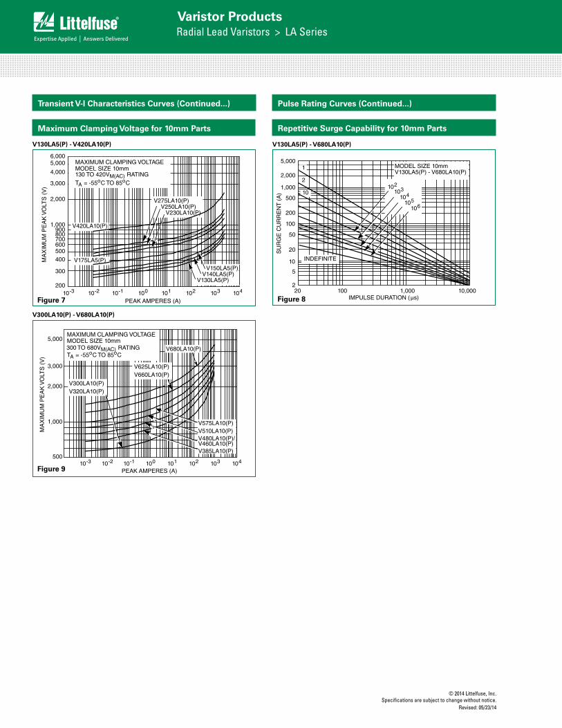
Maximum Clamping Voltage for 10mm Parts
V300LA10(P) - V680LA10(P)
Transient V-I Characteristics Curves (Continued...)
V130LA5(P) - V420LA10(P)
Transient V-I Characteristics Curves
FIGURE 3. CLAMPING VOLTAGE FOR V130LA1(P) - V300LA2(P) FIGURE 4. CLAMPING VOLTAGE FOR V130LA2(P) - V300LA4(P)
FIGURE 5. CLAMPING VOLTAGE FOR V320LA7(P) - V480LA7(P) FIGURE 6. CLAMPING VOLTAGE FOR V130LA5(P) - V420LA10(P)
FIGURE 7. CLAMPING VOLTAGE FOR V300LA10(P) - V680LA10(P) FIGURE 8. CLAMPING VOLTAGE FOR V130LA10A(P) - V320LA20A
200
6,0005,000
4,000
3,000
1,000900800700600500400
300
10-3 10-2 10-1 100 101 102 104
MA
XIM
UM
PE
AK
VO
LTS
(V
)
PEAK AMPERES (A)
2,000
103
V150LA1(P)
V130LA1(P)
V300LA2(P)
V275LA2(P)V250LA2(P)
MAXIMUM CLAMPING VOLTAGEMODEL SIZE 7mm130 TO 300VM(AC) RATINGTA = -55oC TO 85oC
10-3 10-2 10-1 100 101 102 104
MA
XIM
UM
PE
AK
VO
LTS
(V
)
PEAK AMPERES (A)103
4,000
3,000
2,000
1,000900800700600500400
300
200
100
MAXIMUM CLAMPING VOLTAGEMODEL SIZE 7mm130 TO 300VM(AC) RATINGTA = -55oC TO 85oC V300LA4(P)
V275LA4(P)V250LA4(P)
V230LA4(P)
V130LA2(P)V140LA2(P)
V150LA2(P)V175LA2(P)
MAXIMUM CLAMPING VOLTAGEMODEL SIZE 7mm
TA = -55oC TO 85oC320 TO 480VM(AC) RATING
V420LA7(P)V385LA7(P)
V320LA7(P)
V460LA7(P)V480LA7(P)
10-3 10-2 10-1 100 101 102 104103
5,000
3,000
2,000
1,000
500
PEAK AMPERES (A)
MA
XIM
UM
PE
AK
VO
LTS
(V
)
200
6,0005,000
4,000
3,000
1,000900800700600500400
300
10-3 10-2 10-1 100 101 102 104
MA
XIM
UM
PE
AK
VO
LTS
(V
)
PEAK AMPERES (A)
2,000
103
V275LA10(P)V250LA10(P)
MAXIMUM CLAMPING VOLTAGEMODEL SIZE 10mm130 TO 420VM(AC) RATINGTA = -55oC TO 85oC
V230LA10(P)
V420LA10(P)
V175LA5(P)
V130LA5(P)V140LA5(P)
V150LA5(P)
10-3 10-2 10-1 100 101 102 104103
5,000
3,000
2,000
1,000
500
V575LA10(P)V510LA10(P)V480LA10(P)/V460LA10(P)V385LA10(P)
V300LA10(P)V320LA10(P)
PEAK AMPERES (A)
V625LA10(P)V660LA10(P)
MAXIMUM CLAMPING VOLTAGEMODEL SIZE 10mm
TA = -55oC TO 85oC300 TO 680VM(AC) RATING
MA
XIM
UM
PE
AK
VO
LTS
(V
)
200
6,0005,0004,000
3,000
1,000900800700600500400
300
10-3 10-2 10-1 100 101 102 104
MA
XIM
UM
PE
AK
VO
LTS
(V
)
PEAK AMPERES (A)
2,000
103
V275LA20A(P)V250LA20A(P)
MAXIMUM CLAMPING VOLTAGEMODEL SIZE 14mm130 TO 320VM(AC) RATINGTA = -55oC TO 85oC
V230LA20A(P)
V175LA10A(P)
V130LA10A(P)V140LA10A(P)
V150LA10A(P)
V320LA20A(P)V300LA20A(P)
V680LA10(P)
Repetitive Surge Capability for 10mm Parts
V130LA5(P) - V680LA10(P)
FIGURE 14. SURGE CURRENT RATING CURVES FOR V130LA1(P) - V480LA7(P)
FIGURE 15. SURGE CURRENT RATING CURVES FOR V130LA5(P) - V680LA10(P)
FIGURE 16. SURGE CURRENT RATING CURVES FOR V130LA10A(P) - V320LA20A(P)
FIGURE 17. SURGE CURRENT RATING CURVES FOR V385LA20A(P) - V1000LA80A(P)
FIGURE 18. SURGE CURRENT RATING CURVES FOR V130LA20A(P) - V320LA40B(P)
FIGURE 19. SURGE CURRENT RATING CURVES FOR V385LA40B(P) - V1000LA160B(P)
2,000
1,000
200
100
50
20
10
5
1
2
500
20 100 1,000 10,000IMPULSE DURATION (µs)
SU
RG
E C
UR
RE
NT
(A
)
1
2
10
102104
105
106
MODEL SIZE 7mmV130LA1(P) - V480LA7(P)
103
INDEFINITE
5,000
2,000
200
100
50
20
10
5
2
500
20 100 1,000 10,000IMPULSE DURATION (µs)
SU
RG
E C
UR
RE
NT
(A
)
1
2
10104
105
106
MODEL SIZE 10mmV130LA5(P) - V680LA10(P)
103
INDEFINITE
1,000 102
5,000
2,000
200
100
50
20
10
5
2
500
20 100 1,000 10,000IMPULSE DURATION (µs)
SU
RG
E C
UR
RE
NT
(A
)
12
10
104
105
106
MODEL SIZE 14mmV130LA10A(P) - V320LA20A(P)
103
INDEFINITE
1,000 102
5,000
2,000
200
100
50
20
10
5
2
500
20 100 1,000 10,000IMPULSE DURATION (µs)
SU
RG
E C
UR
RE
NT
(A
)
12
10
104
105
106
MODEL SIZE 14mmV385LA20A(P) - V1000LA80A(P)
103
INDEFINITE
1,000 102
10,000
2,000
200
100
50
20
10
5
2
500
20 100 1,000 10,000IMPULSE DURATION (µs)
SU
RG
E C
UR
RE
NT
(A
)
12
104
105
106
MODEL SIZE 20mmV130LA20A(P) - V320LA40B(P)
103
INDEFINITE
1,000
10210
5,000
1
10,000
2,000
200
100
50
20
10
5
2
500
20 100 1,000 10,000IMPULSE DURATION (µs)
SU
RG
E C
UR
RE
NT
(A
)
12
104
105
106
MODEL SIZE 20mmV385LA40B(P) - V1000LA160B(P)
103
INDEFINITE
1,000
10210
5,000
1
Pulse Rating Curves (Continued...)
Figure 7
Figure 9
Figure 8
© 2014 Littelfuse, Inc.Specifications are subject to change without notice. Revised: 05/23/14
Varistor ProductsRadial Lead Varistors > LA Series
LA S
erie
s
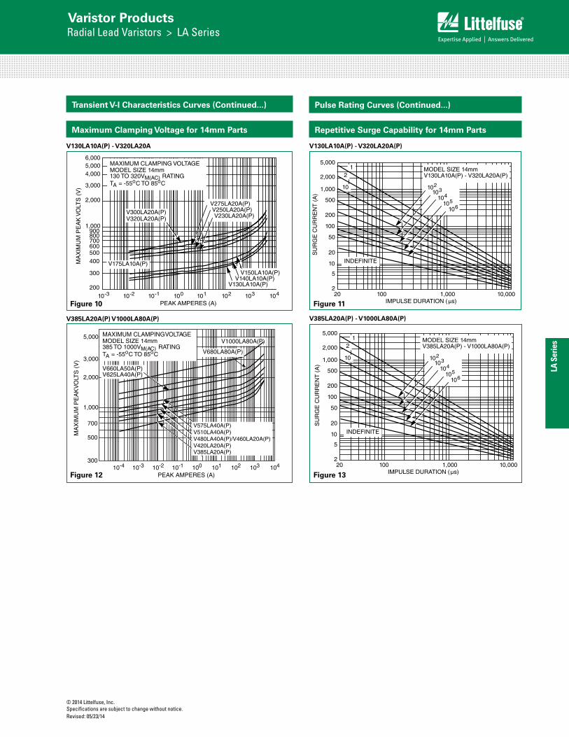
Maximum Clamping Voltage for 14mm Parts
V130LA10A(P) - V320LA20A
Transient V-I Characteristics Curves
FIGURE 3. CLAMPING VOLTAGE FOR V130LA1(P) - V300LA2(P) FIGURE 4. CLAMPING VOLTAGE FOR V130LA2(P) - V300LA4(P)
FIGURE 5. CLAMPING VOLTAGE FOR V320LA7(P) - V480LA7(P) FIGURE 6. CLAMPING VOLTAGE FOR V130LA5(P) - V420LA10(P)
FIGURE 7. CLAMPING VOLTAGE FOR V300LA10(P) - V680LA10(P) FIGURE 8. CLAMPING VOLTAGE FOR V130LA10A(P) - V320LA20A
200
6,0005,000
4,000
3,000
1,000900800700600500400
300
10-3 10-2 10-1 100 101 102 104
MA
XIM
UM
PE
AK
VO
LTS
(V
)
PEAK AMPERES (A)
2,000
103
V150LA1(P)
V130LA1(P)
V300LA2(P)
V275LA2(P)V250LA2(P)
MAXIMUM CLAMPING VOLTAGEMODEL SIZE 7mm130 TO 300VM(AC) RATINGTA = -55oC TO 85oC
10-3 10-2 10-1 100 101 102 104
MA
XIM
UM
PE
AK
VO
LTS
(V
)
PEAK AMPERES (A)103
4,000
3,000
2,000
1,000900800700600500400
300
200
100
MAXIMUM CLAMPING VOLTAGEMODEL SIZE 7mm130 TO 300VM(AC) RATINGTA = -55oC TO 85oC V300LA4(P)
V275LA4(P)V250LA4(P)
V230LA4(P)
V130LA2(P)V140LA2(P)
V150LA2(P)V175LA2(P)
MAXIMUM CLAMPING VOLTAGEMODEL SIZE 7mm
TA = -55oC TO 85oC320 TO 480VM(AC) RATING
V420LA7(P)V385LA7(P)
V320LA7(P)
V460LA7(P)V480LA7(P)
10-3 10-2 10-1 100 101 102 104103
5,000
3,000
2,000
1,000
500
PEAK AMPERES (A)
MA
XIM
UM
PE
AK
VO
LTS
(V
)
200
6,0005,000
4,000
3,000
1,000900800700600500400
300
10-3 10-2 10-1 100 101 102 104
MA
XIM
UM
PE
AK
VO
LTS
(V
)
PEAK AMPERES (A)
2,000
103
V275LA10(P)V250LA10(P)
MAXIMUM CLAMPING VOLTAGEMODEL SIZE 10mm130 TO 420VM(AC) RATINGTA = -55oC TO 85oC
V230LA10(P)
V420LA10(P)
V175LA5(P)
V130LA5(P)V140LA5(P)
V150LA5(P)
10-3 10-2 10-1 100 101 102 104103
5,000
3,000
2,000
1,000
500
V575LA10(P)V510LA10(P)V480LA10(P)/V460LA10(P)V385LA10(P)
V300LA10(P)V320LA10(P)
PEAK AMPERES (A)
V625LA10(P)V660LA10(P)
MAXIMUM CLAMPING VOLTAGEMODEL SIZE 10mm
TA = -55oC TO 85oC300 TO 680VM(AC) RATING
MA
XIM
UM
PE
AK
VO
LTS
(V
)
200
6,0005,0004,000
3,000
1,000900800700600500400
300
10-3 10-2 10-1 100 101 102 104
MA
XIM
UM
PE
AK
VO
LTS
(V
)
PEAK AMPERES (A)
2,000
103
V275LA20A(P)V250LA20A(P)
MAXIMUM CLAMPING VOLTAGEMODEL SIZE 14mm130 TO 320VM(AC) RATINGTA = -55oC TO 85oC
V230LA20A(P)
V175LA10A(P)
V130LA10A(P)V140LA10A(P)
V150LA10A(P)
V320LA20A(P)V300LA20A(P)
V680LA10(P)
FIGURE 9. CLAMPING VOLTAGE FOR V385LA20A(P) - V1000LA80A(P)
FIGURE 10. CLAMPING VOLTAGE FOR V130LA20A(P) - V275LA40A(P)
FIGURE 11. CLAMPING VOLTAGE FOR V130LA20B(P) - V275LA40(P) FIGURE 12. CLAMPING VOLTAGE FOR V140LA20A(P) - V230LA40A(P)
FIGURE 13. CLAMPING VOLTAGE FOR V300LA40A - V1000LA160B
5,000
3,000
1,000
500
30010-3 10-2 10-1 100 101 102 104
MA
XIM
UM
PE
AK
VO
LTS
(V
)
PEAK AMPERES (A)
2,000
10310-4
V1000LA80A(P)
V660LA50A(P)
MAXIMUM CLAMPING VOLTAGEMODEL SIZE 14mm385 TO 1000VM(AC) RATINGTA = -55oC TO 85oC
700
V625LA40A(P)
3,000
2,000
1,000900800700600500
400
300
20010-3 10-2 10-1 100 101 102 104
MA
XIM
UM
PE
AK
VO
LTS
(V
)
PEAK AMPERES (A)103
V275LA40A(P)
V250LA40A(P)
V150LA20A(P)V130LA20A(P)
V175LA20A(P)
MAXIMUM CLAMPING VOLTAGEMODEL SIZE 20mm130 TO 275VM(AC) RATINGTA = -55oC TO 85oC
3,000
2,000
1,000900800700600500
400
300
20010-3 10-2 10-1 100 101 102 104
MA
XIM
UM
PE
AK
VO
LTS
(V
)
PEAK AMPERES (A)103
V275LA40B(P)
V250LA40B(P)
V130LA20B(P)
V150LA20B(P)
MAXIMUM CLAMPING VOLTAGEMODEL SIZE 20mm130 TO 275VM(AC) RATINGTA = -55oC TO 85oC
3,000
2,000
500
20010-3 10-2 10-1 100 101 102 104
MA
XIM
UM
PE
AK
VO
LTS
(V
)
PEAK AMPERES (A)
1,000
103
MAXIMUM CLAMPING VOLTAGEMODEL SIZE 20mm140 TO 230VM(AC) RATINGTA = -55oC TO 85oC
300V140LA20A(P)
V230LA40A(P)
5,000
3,000
1,000
50010-3 10-2 10-1 100 101 102 104
MA
XIM
UM
PE
AK
VO
LTS
(V
)
PEAK AMPERES (A)
2,000
103
V625LA80B(P)V660LA100B(P)
V1000LA160B(P)
MAXIMUM CLAMPING VOLTAGEMODEL SIZE 20mm300 TO 1000VM(AC) RATINGTA = -55oC TO 85oC
V575LA80B(P)
V680LA80A(P)
V510LA80B(P)V480LA80B(P)/V460LA40B(P)
V680LA100B(P)
V420LA40B(P)V385LA40B(P)V320LA40B(P)V300LA40A(P)
V575LA40A(P)V510LA40A(P)V480LA40A(P)/V460LA20A(P)V420LA20A(P)V385LA20A(P)
V385LA20A(P) V1000LA80A(P)
Transient V-I Characteristics Curves (Continued...)
Repetitive Surge Capability for 14mm Parts
V130LA10A(P) - V320LA20A(P) FIGURE 14. SURGE CURRENT RATING CURVES FOR
V130LA1(P) - V480LA7(P) FIGURE 15. SURGE CURRENT RATING CURVES FOR
V130LA5(P) - V680LA10(P)
FIGURE 16. SURGE CURRENT RATING CURVES FOR V130LA10A(P) - V320LA20A(P)
FIGURE 17. SURGE CURRENT RATING CURVES FOR V385LA20A(P) - V1000LA80A(P)
FIGURE 18. SURGE CURRENT RATING CURVES FOR V130LA20A(P) - V320LA40B(P)
FIGURE 19. SURGE CURRENT RATING CURVES FOR V385LA40B(P) - V1000LA160B(P)
2,000
1,000
200
100
50
20
10
5
1
2
500
20 100 1,000 10,000IMPULSE DURATION (µs)
SU
RG
E C
UR
RE
NT
(A
)
1
2
10
102104
105
106
MODEL SIZE 7mmV130LA1(P) - V480LA7(P)
103
INDEFINITE
5,000
2,000
200
100
50
20
10
5
2
500
20 100 1,000 10,000IMPULSE DURATION (µs)
SU
RG
E C
UR
RE
NT
(A
)
1
2
10104
105
106
MODEL SIZE 10mmV130LA5(P) - V680LA10(P)
103
INDEFINITE
1,000 102
5,000
2,000
200
100
50
20
10
5
2
500
20 100 1,000 10,000IMPULSE DURATION (µs)
SU
RG
E C
UR
RE
NT
(A
)
12
10
104
105
106
MODEL SIZE 14mmV130LA10A(P) - V320LA20A(P)
103
INDEFINITE
1,000 102
5,000
2,000
200
100
50
20
10
5
2
500
20 100 1,000 10,000IMPULSE DURATION (µs)
SU
RG
E C
UR
RE
NT
(A
)
12
10
104
105
106
MODEL SIZE 14mmV385LA20A(P) - V1000LA80A(P)
103
INDEFINITE
1,000 102
10,000
2,000
200
100
50
20
10
5
2
500
20 100 1,000 10,000IMPULSE DURATION (µs)
SU
RG
E C
UR
RE
NT
(A
)
12
104
105
106
MODEL SIZE 20mmV130LA20A(P) - V320LA40B(P)
103
INDEFINITE
1,000
10210
5,000
1
10,000
2,000
200
100
50
20
10
5
2
500
20 100 1,000 10,000IMPULSE DURATION (µs)
SU
RG
E C
UR
RE
NT
(A
)
12
104
105
106
MODEL SIZE 20mmV385LA40B(P) - V1000LA160B(P)
103
INDEFINITE
1,000
10210
5,000
1
V385LA20A(P) - V1000LA80A(P)
FIGURE 14. SURGE CURRENT RATING CURVES FOR V130LA1(P) - V480LA7(P)
FIGURE 15. SURGE CURRENT RATING CURVES FOR V130LA5(P) - V680LA10(P)
FIGURE 16. SURGE CURRENT RATING CURVES FOR V130LA10A(P) - V320LA20A(P)
FIGURE 17. SURGE CURRENT RATING CURVES FOR V385LA20A(P) - V1000LA80A(P)
FIGURE 18. SURGE CURRENT RATING CURVES FOR V130LA20A(P) - V320LA40B(P)
FIGURE 19. SURGE CURRENT RATING CURVES FOR V385LA40B(P) - V1000LA160B(P)
2,000
1,000
200
100
50
20
10
5
1
2
500
20 100 1,000 10,000IMPULSE DURATION (µs)
SU
RG
E C
UR
RE
NT
(A
)
1
2
10
102104
105
106
MODEL SIZE 7mmV130LA1(P) - V480LA7(P)
103
INDEFINITE
5,000
2,000
200
100
50
20
10
5
2
500
20 100 1,000 10,000IMPULSE DURATION (µs)
SU
RG
E C
UR
RE
NT
(A
)
1
2
10104
105
106
MODEL SIZE 10mmV130LA5(P) - V680LA10(P)
103
INDEFINITE
1,000 102
5,000
2,000
200
100
50
20
10
5
2
500
20 100 1,000 10,000IMPULSE DURATION (µs)
SU
RG
E C
UR
RE
NT
(A
)
12
10
104
105
106
MODEL SIZE 14mmV130LA10A(P) - V320LA20A(P)
103
INDEFINITE
1,000 102
5,000
2,000
200
100
50
20
10
5
2
500
20 100 1,000 10,000IMPULSE DURATION (µs)
SU
RG
E C
UR
RE
NT
(A
)
12
10
104
105
106
MODEL SIZE 14mmV385LA20A(P) - V1000LA80A(P)
103
INDEFINITE
1,000 102
10,000
2,000
200
100
50
20
10
5
2
500
20 100 1,000 10,000IMPULSE DURATION (µs)
SU
RG
E C
UR
RE
NT
(A
)
12
104
105
106
MODEL SIZE 20mmV130LA20A(P) - V320LA40B(P)
103
INDEFINITE
1,000
10210
5,000
1
10,000
2,000
200
100
50
20
10
5
2
500
20 100 1,000 10,000IMPULSE DURATION (µs)
SU
RG
E C
UR
RE
NT
(A
)
12
104
105
106
MODEL SIZE 20mmV385LA40B(P) - V1000LA160B(P)
103
INDEFINITE
1,000
10210
5,000
1
Pulse Rating Curves (Continued...)
Figure 10 Figure 11
Figure 12 Figure 13
© 2014 Littelfuse, Inc.Specifications are subject to change without notice.
Revised: 05/23/14
Varistor ProductsRadial Lead Varistors > LA Series
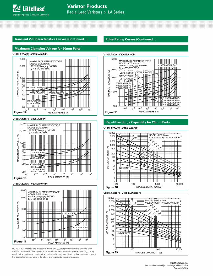
Maximum Clamping Voltage for 20mm Parts
FIGURE 9. CLAMPING VOLTAGE FOR V385LA20A(P) - V1000LA80A(P)
FIGURE 10. CLAMPING VOLTAGE FOR V130LA20A(P) - V275LA40A(P)
FIGURE 11. CLAMPING VOLTAGE FOR V130LA20B(P) - V275LA40(P) FIGURE 12. CLAMPING VOLTAGE FOR V140LA20A(P) - V230LA40A(P)
FIGURE 13. CLAMPING VOLTAGE FOR V300LA40A - V1000LA160B
5,000
3,000
1,000
500
30010-3 10-2 10-1 100 101 102 104
MA
XIM
UM
PE
AK
VO
LTS
(V
)
PEAK AMPERES (A)
2,000
10310-4
V1000LA80A(P)
V660LA50A(P)
MAXIMUM CLAMPING VOLTAGEMODEL SIZE 14mm385 TO 1000VM(AC) RATINGTA = -55oC TO 85oC
700
V625LA40A(P)
3,000
2,000
1,000900800700600500
400
300
20010-3 10-2 10-1 100 101 102 104
MA
XIM
UM
PE
AK
VO
LTS
(V
)
PEAK AMPERES (A)103
V275LA40A(P)
V250LA40A(P)
V150LA20A(P)V130LA20A(P)
V175LA20A(P)
MAXIMUM CLAMPING VOLTAGEMODEL SIZE 20mm130 TO 275VM(AC) RATINGTA = -55oC TO 85oC
3,000
2,000
1,000900800700600500
400
300
20010-3 10-2 10-1 100 101 102 104
MA
XIM
UM
PE
AK
VO
LTS
(V
)
PEAK AMPERES (A)103
V275LA40B(P)
V250LA40B(P)
V130LA20B(P)
V150LA20B(P)
MAXIMUM CLAMPING VOLTAGEMODEL SIZE 20mm130 TO 275VM(AC) RATINGTA = -55oC TO 85oC
3,000
2,000
500
20010-3 10-2 10-1 100 101 102 104
MA
XIM
UM
PE
AK
VO
LTS
(V
)
PEAK AMPERES (A)
1,000
103
MAXIMUM CLAMPING VOLTAGEMODEL SIZE 20mm140 TO 230VM(AC) RATINGTA = -55oC TO 85oC
300V140LA20A(P)
V230LA40A(P)
5,000
3,000
1,000
50010-3 10-2 10-1 100 101 102 104
MA
XIM
UM
PE
AK
VO
LTS
(V
)PEAK AMPERES (A)
2,000
103
V625LA80B(P)V660LA100B(P)
V1000LA160B(P)
MAXIMUM CLAMPING VOLTAGEMODEL SIZE 20mm300 TO 1000VM(AC) RATINGTA = -55oC TO 85oC
V575LA80B(P)
V680LA80A(P)
V510LA80B(P)V480LA80B(P)/V460LA40B(P)
V680LA100B(P)
V420LA40B(P)V385LA40B(P)V320LA40B(P)V300LA40A(P)
V575LA40A(P)V510LA40A(P)V480LA40A(P)/V460LA20A(P)V420LA20A(P)V385LA20A(P)
V300LA40A - V1000LA160B
Transient V-I Characteristics Curves (Continued...)
Repetitive Surge Capability for 20mm Parts
V130LA20A(P) - V320LA40B(P)
FIGURE 14. SURGE CURRENT RATING CURVES FOR V130LA1(P) - V480LA7(P)
FIGURE 15. SURGE CURRENT RATING CURVES FOR V130LA5(P) - V680LA10(P)
FIGURE 16. SURGE CURRENT RATING CURVES FOR V130LA10A(P) - V320LA20A(P)
FIGURE 17. SURGE CURRENT RATING CURVES FOR V385LA20A(P) - V1000LA80A(P)
FIGURE 18. SURGE CURRENT RATING CURVES FOR V130LA20A(P) - V320LA40B(P)
FIGURE 19. SURGE CURRENT RATING CURVES FOR V385LA40B(P) - V1000LA160B(P)
2,000
1,000
200
100
50
20
10
5
1
2
500
20 100 1,000 10,000IMPULSE DURATION (µs)
SU
RG
E C
UR
RE
NT
(A
)
1
2
10
102104
105
106
MODEL SIZE 7mmV130LA1(P) - V480LA7(P)
103
INDEFINITE
5,000
2,000
200
100
50
20
10
5
2
500
20 100 1,000 10,000IMPULSE DURATION (µs)
SU
RG
E C
UR
RE
NT
(A
)
1
2
10104
105
106
MODEL SIZE 10mmV130LA5(P) - V680LA10(P)
103
INDEFINITE
1,000 102
5,000
2,000
200
100
50
20
10
5
2
500
20 100 1,000 10,000IMPULSE DURATION (µs)
SU
RG
E C
UR
RE
NT
(A
)
12
10
104
105
106
MODEL SIZE 14mmV130LA10A(P) - V320LA20A(P)
103
INDEFINITE
1,000 102
5,000
2,000
200
100
50
20
10
5
2
500
20 100 1,000 10,000IMPULSE DURATION (µs)
SU
RG
E C
UR
RE
NT
(A
)
12
10
104
105
106
MODEL SIZE 14mmV385LA20A(P) - V1000LA80A(P)
103
INDEFINITE
1,000 102
10,000
2,000
200
100
50
20
10
5
2
500
20 100 1,000 10,000IMPULSE DURATION (µs)
SU
RG
E C
UR
RE
NT
(A
)
12
104
105
106
MODEL SIZE 20mmV130LA20A(P) - V320LA40B(P)
103
INDEFINITE
1,000
10210
5,000
1
10,000
2,000
200
100
50
20
10
5
2
500
20 100 1,000 10,000IMPULSE DURATION (µs)
SU
RG
E C
UR
RE
NT
(A
)
12
104
105
106
MODEL SIZE 20mmV385LA40B(P) - V1000LA160B(P)
103
INDEFINITE
1,000
10210
5,000
1
Pulse Rating Curves (Continued...)
V385LA40B(P) - V1000LA160B(P)
FIGURE 14. SURGE CURRENT RATING CURVES FOR V130LA1(P) - V480LA7(P)
FIGURE 15. SURGE CURRENT RATING CURVES FOR V130LA5(P) - V680LA10(P)
FIGURE 16. SURGE CURRENT RATING CURVES FOR V130LA10A(P) - V320LA20A(P)
FIGURE 17. SURGE CURRENT RATING CURVES FOR V385LA20A(P) - V1000LA80A(P)
FIGURE 18. SURGE CURRENT RATING CURVES FOR V130LA20A(P) - V320LA40B(P)
FIGURE 19. SURGE CURRENT RATING CURVES FOR V385LA40B(P) - V1000LA160B(P)
2,000
1,000
200
100
50
20
10
5
1
2
500
20 100 1,000 10,000IMPULSE DURATION (µs)
SU
RG
E C
UR
RE
NT
(A
)
1
2
10
102104
105
106
MODEL SIZE 7mmV130LA1(P) - V480LA7(P)
103
INDEFINITE
5,000
2,000
200
100
50
20
10
5
2
500
20 100 1,000 10,000IMPULSE DURATION (µs)
SU
RG
E C
UR
RE
NT
(A
)
1
2
10104
105
106
MODEL SIZE 10mmV130LA5(P) - V680LA10(P)
103
INDEFINITE
1,000 102
5,000
2,000
200
100
50
20
10
5
2
500
20 100 1,000 10,000IMPULSE DURATION (µs)
SU
RG
E C
UR
RE
NT
(A
)
12
10
104
105
106
MODEL SIZE 14mmV130LA10A(P) - V320LA20A(P)
103
INDEFINITE
1,000 102
5,000
2,000
200
100
50
20
10
5
2
500
20 100 1,000 10,000IMPULSE DURATION (µs)
SU
RG
E C
UR
RE
NT
(A
)
12
10
104
105
106
MODEL SIZE 14mmV385LA20A(P) - V1000LA80A(P)
103
INDEFINITE
1,000 102
10,000
2,000
200
100
50
20
10
5
2
500
20 100 1,000 10,000IMPULSE DURATION (µs)
SU
RG
E C
UR
RE
NT
(A
)
12
104
105
106
MODEL SIZE 20mmV130LA20A(P) - V320LA40B(P)
103
INDEFINITE
1,000
10210
5,000
1
10,000
2,000
200
100
50
20
10
5
2
500
20 100 1,000 10,000IMPULSE DURATION (µs)
SU
RG
E C
UR
RE
NT
(A
)
12
104
105
106
MODEL SIZE 20mmV385LA40B(P) - V1000LA160B(P)
103
INDEFINITE
1,000
10210
5,000
1NOTE: If pulse ratings are exceeded, a shift of VN(DC) (at specified current) of more than +/-10% could result. This type of shift, which normally results in a decrease of VN(DC), may result in the device not meeting the original published specifications, but does not prevent the device from continuing to function, and to provide ample protection.
V130LA20A(P) - V275LA40A(P)
FIGURE 9. CLAMPING VOLTAGE FOR V385LA20A(P) - V1000LA80A(P)
FIGURE 10. CLAMPING VOLTAGE FOR V130LA20A(P) - V275LA40A(P)
FIGURE 11. CLAMPING VOLTAGE FOR V130LA20B(P) - V275LA40(P) FIGURE 12. CLAMPING VOLTAGE FOR V140LA20A(P) - V230LA40A(P)
FIGURE 13. CLAMPING VOLTAGE FOR V300LA40A - V1000LA160B
5,000
3,000
1,000
500
30010-3 10-2 10-1 100 101 102 104
MA
XIM
UM
PE
AK
VO
LTS
(V
)
PEAK AMPERES (A)
2,000
10310-4
V1000LA80A(P)
V660LA50A(P)
MAXIMUM CLAMPING VOLTAGEMODEL SIZE 14mm385 TO 1000VM(AC) RATINGTA = -55oC TO 85oC
700
V625LA40A(P)
3,000
2,000
1,000900800700600500
400
300
20010-3 10-2 10-1 100 101 102 104
MA
XIM
UM
PE
AK
VO
LTS
(V
)
PEAK AMPERES (A)103
V275LA40A(P)
V250LA40A(P)
V150LA20A(P)V130LA20A(P)
V175LA20A(P)
MAXIMUM CLAMPING VOLTAGEMODEL SIZE 20mm130 TO 275VM(AC) RATINGTA = -55oC TO 85oC
3,000
2,000
1,000900800700600500
400
300
20010-3 10-2 10-1 100 101 102 104
MA
XIM
UM
PE
AK
VO
LTS
(V
)
PEAK AMPERES (A)103
V275LA40B(P)
V250LA40B(P)
V130LA20B(P)
V150LA20B(P)
MAXIMUM CLAMPING VOLTAGEMODEL SIZE 20mm130 TO 275VM(AC) RATINGTA = -55oC TO 85oC
3,000
2,000
500
20010-3 10-2 10-1 100 101 102 104
MA
XIM
UM
PE
AK
VO
LTS
(V
)
PEAK AMPERES (A)
1,000
103
MAXIMUM CLAMPING VOLTAGEMODEL SIZE 20mm140 TO 230VM(AC) RATINGTA = -55oC TO 85oC
300V140LA20A(P)
V230LA40A(P)
5,000
3,000
1,000
50010-3 10-2 10-1 100 101 102 104
MA
XIM
UM
PE
AK
VO
LTS
(V
)
PEAK AMPERES (A)
2,000
103
V625LA80B(P)V660LA100B(P)
V1000LA160B(P)
MAXIMUM CLAMPING VOLTAGEMODEL SIZE 20mm300 TO 1000VM(AC) RATINGTA = -55oC TO 85oC
V575LA80B(P)
V680LA80A(P)
V510LA80B(P)V480LA80B(P)/V460LA40B(P)
V680LA100B(P)
V420LA40B(P)V385LA40B(P)V320LA40B(P)V300LA40A(P)
V575LA40A(P)V510LA40A(P)V480LA40A(P)/V460LA20A(P)V420LA20A(P)V385LA20A(P)
FIGURE 9. CLAMPING VOLTAGE FOR V385LA20A(P) - V1000LA80A(P)
FIGURE 10. CLAMPING VOLTAGE FOR V130LA20A(P) - V275LA40A(P)
FIGURE 11. CLAMPING VOLTAGE FOR V130LA20B(P) - V275LA40(P) FIGURE 12. CLAMPING VOLTAGE FOR V140LA20A(P) - V230LA40A(P)
FIGURE 13. CLAMPING VOLTAGE FOR V300LA40A - V1000LA160B
5,000
3,000
1,000
500
30010-3 10-2 10-1 100 101 102 104
MA
XIM
UM
PE
AK
VO
LTS
(V
)
PEAK AMPERES (A)
2,000
10310-4
V1000LA80A(P)
V660LA50A(P)
MAXIMUM CLAMPING VOLTAGEMODEL SIZE 14mm385 TO 1000VM(AC) RATINGTA = -55oC TO 85oC
700
V625LA40A(P)
3,000
2,000
1,000900800700600500
400
300
20010-3 10-2 10-1 100 101 102 104
MA
XIM
UM
PE
AK
VO
LTS
(V
)PEAK AMPERES (A)
103
V275LA40A(P)
V250LA40A(P)
V150LA20A(P)V130LA20A(P)
V175LA20A(P)
MAXIMUM CLAMPING VOLTAGEMODEL SIZE 20mm130 TO 275VM(AC) RATINGTA = -55oC TO 85oC
3,000
2,000
1,000900800700600500
400
300
20010-3 10-2 10-1 100 101 102 104
MA
XIM
UM
PE
AK
VO
LTS
(V
)
PEAK AMPERES (A)103
V275LA40B(P)
V250LA40B(P)
V130LA20B(P)
V150LA20B(P)
MAXIMUM CLAMPING VOLTAGEMODEL SIZE 20mm130 TO 275VM(AC) RATINGTA = -55oC TO 85oC
3,000
2,000
500
20010-3 10-2 10-1 100 101 102 104
MA
XIM
UM
PE
AK
VO
LTS
(V
)
PEAK AMPERES (A)
1,000
103
MAXIMUM CLAMPING VOLTAGEMODEL SIZE 20mm140 TO 230VM(AC) RATINGTA = -55oC TO 85oC
300V140LA20A(P)
V230LA40A(P)
5,000
3,000
1,000
50010-3 10-2 10-1 100 101 102 104
MA
XIM
UM
PE
AK
VO
LTS
(V
)
PEAK AMPERES (A)
2,000
103
V625LA80B(P)V660LA100B(P)
V1000LA160B(P)
MAXIMUM CLAMPING VOLTAGEMODEL SIZE 20mm300 TO 1000VM(AC) RATINGTA = -55oC TO 85oC
V575LA80B(P)
V680LA80A(P)
V510LA80B(P)V480LA80B(P)/V460LA40B(P)
V680LA100B(P)
V420LA40B(P)V385LA40B(P)V320LA40B(P)V300LA40A(P)
V575LA40A(P)V510LA40A(P)V480LA40A(P)/V460LA20A(P)V420LA20A(P)V385LA20A(P)
V130LA20B(P) - V275LA40(P)
V130LA20A(P) - V275LA40A(P)
FIGURE 9. CLAMPING VOLTAGE FOR V385LA20A(P) - V1000LA80A(P)
FIGURE 10. CLAMPING VOLTAGE FOR V130LA20A(P) - V275LA40A(P)
FIGURE 11. CLAMPING VOLTAGE FOR V130LA20B(P) - V275LA40(P) FIGURE 12. CLAMPING VOLTAGE FOR V140LA20A(P) - V230LA40A(P)
FIGURE 13. CLAMPING VOLTAGE FOR V300LA40A - V1000LA160B
5,000
3,000
1,000
500
30010-3 10-2 10-1 100 101 102 104
MA
XIM
UM
PE
AK
VO
LTS
(V
)
PEAK AMPERES (A)
2,000
10310-4
V1000LA80A(P)
V660LA50A(P)
MAXIMUM CLAMPING VOLTAGEMODEL SIZE 14mm385 TO 1000VM(AC) RATINGTA = -55oC TO 85oC
700
V625LA40A(P)
3,000
2,000
1,000900800700600500
400
300
20010-3 10-2 10-1 100 101 102 104
MA
XIM
UM
PE
AK
VO
LTS
(V
)
PEAK AMPERES (A)103
V275LA40A(P)
V250LA40A(P)
V150LA20A(P)V130LA20A(P)
V175LA20A(P)
MAXIMUM CLAMPING VOLTAGEMODEL SIZE 20mm130 TO 275VM(AC) RATINGTA = -55oC TO 85oC
3,000
2,000
1,000900800700600500
400
300
20010-3 10-2 10-1 100 101 102 104
MA
XIM
UM
PE
AK
VO
LTS
(V
)
PEAK AMPERES (A)103
V275LA40B(P)
V250LA40B(P)
V130LA20B(P)
V150LA20B(P)
MAXIMUM CLAMPING VOLTAGEMODEL SIZE 20mm130 TO 275VM(AC) RATINGTA = -55oC TO 85oC
3,000
2,000
500
20010-3 10-2 10-1 100 101 102 104
MA
XIM
UM
PE
AK
VO
LTS
(V
)
PEAK AMPERES (A)
1,000
103
MAXIMUM CLAMPING VOLTAGEMODEL SIZE 20mm140 TO 230VM(AC) RATINGTA = -55oC TO 85oC
300V140LA20A(P)
V230LA40A(P)
5,000
3,000
1,000
50010-3 10-2 10-1 100 101 102 104
MA
XIM
UM
PE
AK
VO
LTS
(V
)
PEAK AMPERES (A)
2,000
103
V625LA80B(P)V660LA100B(P)
V1000LA160B(P)
MAXIMUM CLAMPING VOLTAGEMODEL SIZE 20mm300 TO 1000VM(AC) RATINGTA = -55oC TO 85oC
V575LA80B(P)
V680LA80A(P)
V510LA80B(P)V480LA80B(P)/V460LA40B(P)
V680LA100B(P)
V420LA40B(P)V385LA40B(P)V320LA40B(P)V300LA40A(P)
V575LA40A(P)V510LA40A(P)V480LA40A(P)/V460LA20A(P)V420LA20A(P)V385LA20A(P)
Figure 14 Figure 15
Figure 16
Figure 17
Figure 18
Figure 19
© 2014 Littelfuse, Inc.Specifications are subject to change without notice. Revised: 05/23/14
Varistor ProductsRadial Lead Varistors > LA Series
LA S
erie
s
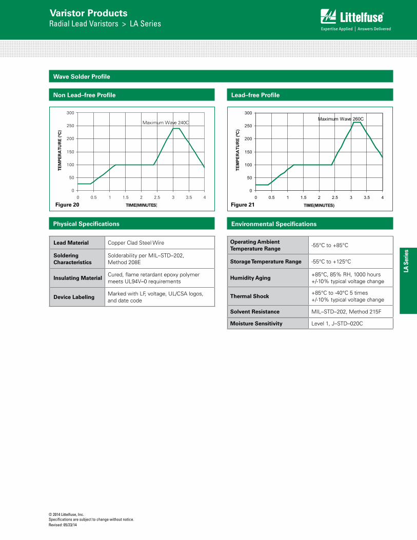
Wave Solder Profile
Operating Ambient Temperature Range
-55°C to +85°C
Storage Temperature Range -55°C to +125°C
Humidity Aging+85°C, 85% RH, 1000 hours +/-10% typical voltage change
Thermal Shock+85°C to -40°C 5 times +/-10% typical voltage change
Solvent Resistance MIL–STD–202, Method 215F
Moisture Sensitivity Level 1, J–STD–020C
Lead Material Copper Clad Steel Wire
Soldering Characteristics
Solderability per MIL–STD–202, Method 208E
Insulating MaterialCured, flame retardant epoxy polymer meets UL94V–0 requirements
Device LabelingMarked with LF, voltage, UL/CSA logos, and date code
Physical Specifications Environmental Specifications
0
50
100
150
200
250
300
0 0.5 1 1.5 2 2.5 3 3.5 4
TIME(MINUTES)
TEM
PE
RA
TUR
E (º
C)
Maximum Wave 240C
Lead–free Profile
0
50
100
150
200
250
300
0 0.5 1 1.5 2 2.5 3 3.5 4
TIME(MINUTES)
TEM
PER
ATU
RE
(ºC)
Maximum Wave 260C
Non Lead–free Profile
Figure 20 Figure 21

© 2014 Littelfuse, Inc.Specifications are subject to change without notice.
Revised: 05/23/14
Varistor ProductsRadial Lead Varistors > LA Series
Product Dimensions (mm)
DimensionVRMS
VoltageModel
7mm Size 10mm Size 14mm Size 20mm Size
Min. mm (in)
Max.mm (in)
Min.mm (in)
Max.mm (in)
Min.mm (in)
Max.mm (in)
Min.mm (in)
Max.mm (in)
A
V130LA-V320LA - 12 (0.472) - 16 (0.630) - 20 (0.787) - 26.5 (1.043)
V385LA-V1000LA - 13 (0.0512) - 17 (0.689) - 20.5 (0.807) - 28 (1.102)
ØD All - 9 (0.354) - 12.5 (0.492) - 17 (0.669) - 23 (0.906)
e All 4 (0.157) 6 (0.236) 6.5 (0.256) 8.5 (0.335) 6.5 (0.256) 8.5 (0.335) 6.5 (0.256)(Note 2)
8.5(Note 2)
e1
V130LA-V320LA 1.5 (0.059) 3.5 (0.138) 1.5 (0.059) 3.5 (0.138) 1.5 (0.059) 3.5 (0.138) 1.5 (0.059) 3.5 (0.138)
V385LA-V1000LA 2.5 (0.098) 5.5 (0.217) 2.5 (0.098) 5.5 (0.217) 2.5 (0.098) 5.5 (0.217) 2.5 (0.098) 5.5 (0.217)
E
V130LA-V320LA - 5.6 (0.220) - 5.6 (0.220) - 5.6 (0.220) - 5.6 (0.220)
V385LA-V510LA - 7.3 (0.287) - 7.3 (0.287) - 7.3 (0.287) - 7.3 (0.287)
V550LA-V680LA - 8.3 (0.327) - 8.3 (0.327) - 8.3 (0.327) - 8.3 (0.327)
V1000LA - - - - - 10.8 (0.425) - 10.8 (0.425)
Øb All(Note 3)
0.585 (0.023)
0.685 (0.027) 0.76 (0.030) 0.86 (0.034) 0.76 (0.030) 0.86 (0.034) 0.76 (0.030)
(Note 2)0.86 (0.034)
(Note 2)
ATRIM All - 15 (0.591) - 19.5 (0.768) - 22.5 (0.886) (NOTE 4)
- 29.0 (1.142)
LTRIM All 2.41 (0.095) 4.69 (0.185) 2.41 (0.095) 4.69 (0.185) 2.41 (0.095) 4.69 (0.185) 2.41 (0.095) 4.69 (0.185)
SYMBOLVOLTAGE
MODEL
VARISTOR MODEL SIZE
7mm 10mm 14mm 20mm
MIN MAX MIN MAX MIN MAX MIN MAX
A V130LA-V320LA
--
12 (0.472)
--
16 (0.630)
--
20 (0.787)
--
26.5 (1.043)
V385LA-V1000LA
--
13(0.0512)
--
17 (0.689)
--
20.5 (0.807)
--
28 (1.102)
øD All --
9 (0.354) --
12.5 (0.492)
--
17 (0.669)
--
23 (0.906)
e All 4 (0.157) 6 (0.236) 6.5 (0.256)
8.5 (0.335)
6.5 (0.256)
8.5 (0.335)
6.5 (0.256)(Note 2)
8.5 (0.335)(Note 2)
e1 V130LA-V320LA
1.5 (0.059)
3.5 (0.138)
1.5 (0.059)
3.5 (0.138)
1.5 (0.059)
3.5 (0.138)
1.5 (0.059)
3.5 (0.138)
V385LA-V1000LA
2.5(0.098)
5.5(0.217)
2.5 (0.098)
5.5 (0.217)
2.5 (0.098)
5.5 (0.217)
2.5 (0.098)
5.5 (0.217)
E V130LA-V320LA
--
5.6 (0.220)
--
5.6 (0.220)
--
5.6 (0.220)
--
5.6 (0.220)
V385LA-V510LA
--
7.3 (0.287)
--
7.3 (0.287)
--
7.3 (0.287)
--
7.3 (0.287)
V1000LA --
--
--
--
--
10.8 (0.425)
--
10.8 (0.425)
øb All(Note 3)
0.585 (0.023)
0.685 (0.027)
0.76 (0.030)
0.86 (0.034)
0.76 (0.030)
0.86 (0.034)
0.76 (0.030) (Note 2)
0.86 (0.034) (Note 2)
NOTES:
1. Dimensions in millimeters, inches in parentheses.
2. 10mm (9mm min, 11mm Max) ALSO AVAILABLE; See Additional Lead Style Options
3. 1000V parts supplied with lead wire of diameter 1.00 ± 0.05 (0.039 ± 0.002).
V550LA-V680LA
--
8.3 (0.327)
--
8.3 (0.327)
--
8.3 (0.327)
--
8.3 (0.327)
*SEATINGPLANE
LTRIM
ATRIM
Notes :1. Dimensions in millimeters, (inches) in parentheses.2. 10mm (9mm Min. & 11mm Max.) ALSO AVAILABLE; see additional lead style options 3. 1000V parts supplied with lead wire of diameter 1.00 -/+ 0.05 (0.039 -/+ 0.002)4. 'A' Max. for V1000LC80A (P) = 24.00 (0.945”)
CRIMPED AND TRIMMED LEAD
Crimped leads are standard on LA types supplied in tape and reel and are denoted by the model letter "T." Model letter "S" denotes straight leads and letter "U" denotes special under-crimped leads.
*Seating plane interpretation per IEC-717

© 2014 Littelfuse, Inc.Specifications are subject to change without notice. Revised: 05/23/14
Varistor ProductsRadial Lead Varistors > LA Series
LA S
erie
s
Tape and Reel Specifications
CRIMPED LEADS "LT" CRIMPED LEADS "LT"
Crimped Leads "ZT" Crimped Leads "ZT"
Straight Leads "ZS"Straight Leads "ZS"
Under-crimped Leads "ZU"
P1P0
E
DPDH DH
W1
W
F t
W2W0
P
DP
C
DbH0
DD0
H1SEATING PLANE
P2
P1
P0
W0
E
DPDH DH
W1
W
F t
W2
P
DP
C
DbH0
DD0
H1SEATING PLANE
P2
P0
DH
E
DHDP
W1
W
F t
W2
P
DP
DbH
DD0
H1
P1
P2
W0
P1P0
P2
DH
E
DHDP
W1
W
F t
W2W0
P
DP
DbH
DD0
H1
U
P1P0
P2
DH
E
DHDP
W1
W
F t
W2W0
P
DP
DbHo
DD0
H1
Under-crimped Leads "ZU"
P0
U
DH
E
DHDP
W1
W
F t
W2
P
DP
DbHo
DD0
H1
P2
W0
P1
UNDER-CRIMPED LEADS "LU" UNDER-CRIMPED LEADS "LU"
Crimped Leads "ZT" Crimped Leads "ZT"
Straight Leads "ZS"Straight Leads "ZS"
Under-crimped Leads "ZU"
P1P0
E
DPDH DH
W1
W
F t
W2W0
P
DP
C
DbH0
DD0
H1SEATING PLANE
P2
P1
P0
W0
E
DPDH DH
W1
W
F t
W2
P
DP
C
DbH0
DD0
H1SEATING PLANE
P2
P0
DH
E
DHDP
W1
W
F t
W2
P
DP
DbH
DD0
H1
P1
P2
W0
P1P0
P2
DH
E
DHDP
W1
W
F t
W2W0
P
DP
DbH
DD0
H1
U
P1P0
P2
DH
E
DHDP
W1
W
F t
W2W0
P
DP
DbHo
DD0
H1
Under-crimped Leads "ZU"
P0
U
DH
E
DHDP
W1
W
F t
W2
P
DP
DbHo
DD0
H1
P2
W0
P1
7mm Devices 10, 14 and 20mm Devices
STRAIGHT LEADS "LS" STRAIGHT LEADS "LS"
Crimped Leads "ZT" Crimped Leads "ZT"
Straight Leads "ZS"Straight Leads "ZS"
Under-crimped Leads "ZU"
P1P0
E
DPDH DH
W1
W
F t
W2W0
P
DP
C
DbH0
DD0
H1SEATING PLANE
P2
P1
P0
W0
E
DPDH DH
W1
W
F t
W2
P
DP
C
DbH0
DD0
H1SEATING PLANE
P2
P0
DH
E
DHDP
W1
W
F t
W2
P
DP
DbH
DD0
H1
P1
P2
W0
P1P0
P2
DH
E
DHDP
W1
W
F t
W2W0
P
DP
DbH
DD0
H1
U
P1P0
P2
DH
E
DHDP
W1
W
F t
W2W0
P
DP
DbHo
DD0
H1
Under-crimped Leads "ZU"
P0
U
DH
E
DHDP
W1
W
F t
W2
P
DP
DbHo
DD0
H1
P2
W0
P1
(Dimensions presented on following page.)

© 2014 Littelfuse, Inc.Specifications are subject to change without notice.
Revised: 05/23/14
Varistor ProductsRadial Lead Varistors > LA Series
Symbol Description Model Size
7mm 10mm 14mm 20mm
P Pitch of Component 12.7 +/- 1.0 25.4 +/- 1.0 25.4 +/- 1.0 25.4 +/- 1.0
P0 Feed Hole Pitch 12.7 +/- 0.2 12.7 +/- 0.2 12.7 +/- 0.2 12.7 +/- 0.2
P1 Feed Hole Center to Pitch 3.85 +/- 0.7 8.85 +/- 0.7 8.85 +/- 0.7 8.85 +/- 0.7
P2 Hole Center to Component Center 6.35 +/- 0.7 12.7 +/- 0.7 12.7 +/- 0.7 12.7 +/- 0.7
F Lead to Lead Distance 5.0 +/- 0.8 7.5 +/-0.8 7.5 +/- 0.8 7.5 +/- 0.8
h Component Alignment 2.0 Max 2.0 Max 2.0 Max 2.0 Max
W Tape Width 18.0 +1.0 / -0.5 18.0 +1.0 / -0.5 18.0 +1.0 / -0.5 18.0 +1.0 / -0.5
W0 Hold Down Tape Width 12.0 +/- 0.3 12.0 +/- 0.3 12.0 +/- 0.3 12.0 +/- 0.3
W1 Hole Position 9.0 +0.75 / -0.50 9.0 +0.75 / -0.50 9.0 +0.75 / -0.50 9.0 +0.75 / -0.50
W2 Hold Down Tape Position 0.5 Max 0.5 Max 0.5 Max 0.5 Max
H Height from Tape Center to Component Base 18.0 +2.0 / -0.0 18.0 +2.0 / -0.0 18.0 +2.0 / -0.0 18.0 +2.0 / -0.0
H0 Seating Plane Height 16.0 +/- 0.5 16.0 +/- 0.5 16.0 +/- 0.5 16.0 +/- 0.5
H1 Component Height 32.0 Max 36.0 Max 40.0 Max 46.5 Max
D0 Feed Hole Diameter 4.0 +/- 0.2 4.0 +/- 0.2 4.0 +/- 0.2 4.0 +/- 0.2
T Total Tape Thickness 0.7 +/- 0.2 0.7 +/- 0.2 0.7 +/- 0.2 0.7 +/- 0.2
U Under-crimp Width 8.0 Max 8.0 Max 8.0 Max 8.0 Max
P Component Alignment 3° Max 1.00mm 3° Max 1.00mm 3° Max 1.00mm 3° Max
Tape and Reel Specifications (continued)
NOTE: Dimensions are in mm.
• ConformstoANSIandEIAspecifications• CanbesuppliedtoIECPublication286-2• Radialdevicesontapearesuppliedwithcrimpedleads,straightleads,orunder-crimpedleads• 7mmpartsareavailableontapeandreelupto480VAConly• 10mmpartsareavailableontapeandreelupto510VAConly• 14mmand20mmpartsareavailableontapeandreelupto550VAConly
Standard Bulk Pack Quantity
Varistor Voltage Model
Standard Bulk Pack Quantity
Varistor Model Size
7mm 10mm 14mm 20mm
130-275 1500 1000 700 500
300-460 1500 1000 600 400
510-625 1500 1000 500 400
660 N/A 1000 500 400
680 N/A 1000 400 300
1000 N/A N/A 300 200
© 2014 Littelfuse, Inc.Specifications are subject to change without notice. Revised: 05/23/14
Varistor ProductsRadial Lead Varistors > LA Series
LA S
erie
s
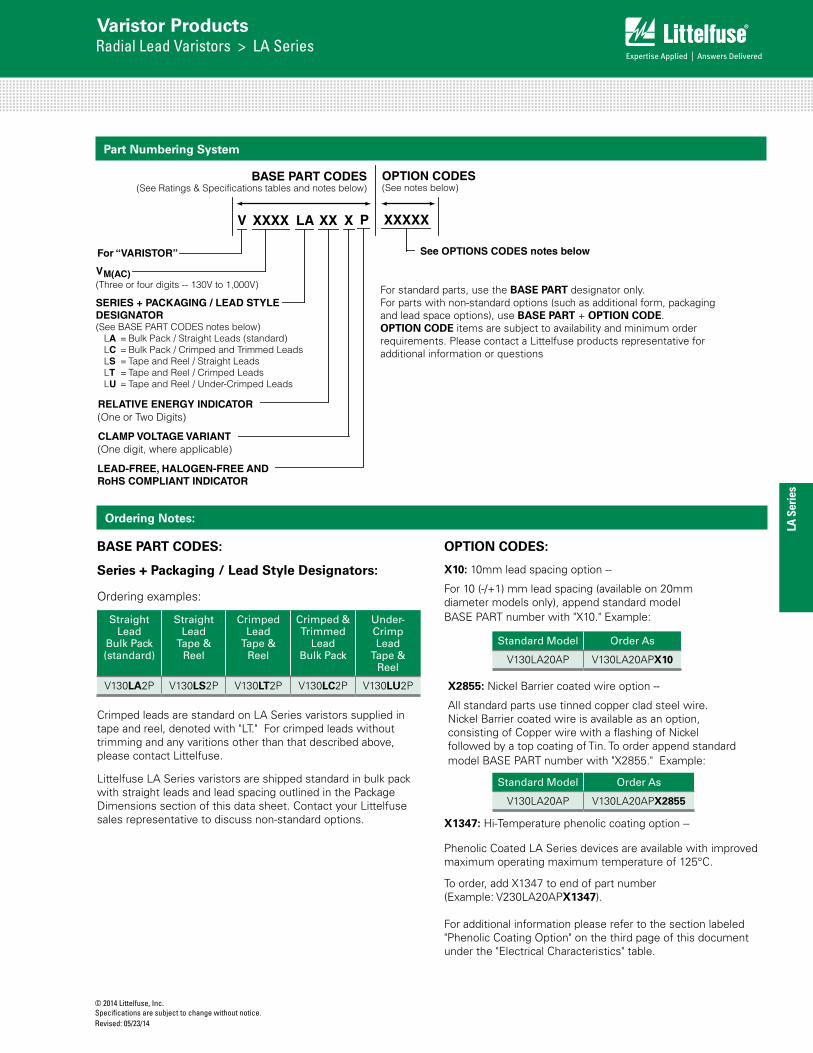
Part Numbering System
XX
For “VARISTOR”
VM(AC)(Three or four digits -- 130V to 1,000V)
V XXXX LA X
RELATIVE ENERGY INDICATOR(One or Two Digits)
CLAMP VOLTAGE VARIANT(One digit, where applicable)
LEAD-FREE, HALOGEN-FREE AND RoHS COMPLIANT INDICATOR
P
See OPTIONS CODES notes below
XXXXX
OPTION CODES(See notes below)
BASE PART CODES(See Ratings & Specifications tables and notes below)
SERIES + PACKAGING / LEAD STYLEDESIGNATOR(See BASE PART CODES notes below)
LA = Bulk Pack / Straight Leads (standard)LC = Bulk Pack / Crimped and Trimmed Leads LS = Tape and Reel / Straight Leads LT = Tape and Reel / Crimped LeadsLU = Tape and Reel / Under-Crimped Leads
Ordering Notes:
Series + Packaging / Lead Style Designators:
Ordering examples:
Straight Lead
Bulk Pack(standard)
Straight Lead
Tape & Reel
Crimped Lead
Tape & Reel
Crimped & Trimmed
LeadBulk Pack
Under-Crimp Lead
Tape & Reel
V130LA2P V130LS2P V130LT2P V130LC2P V130LU2P
Standard Model Order As
V130LA20AP V130LA20APX10
X1347: Hi-Temperature phenolic coating option --
Phenolic Coated LA Series devices are available with improved maximum operating maximum temperature of 125°C.
To order, add X1347 to end of part number (Example: V230LA20APX1347).
For additional information please refer to the section labeled "Phenolic Coating Option" on the third page of this document under the "Electrical Characteristics" table.
Crimped leads are standard on LA Series varistors supplied in tape and reel, denoted with "LT." For crimped leads without trimming and any varitions other than that described above, please contact Littelfuse.
For standard parts, use the BASE PART designator only. For parts with non-standard options (such as additional form, packaging and lead space options), use BASE PART + OPTION CODE. OPTION CODE items are subject to availability and minimum order requirements. Please contact a Littelfuse products representative for additional information or questions
BASE PART CODES: OPTION CODES:
Standard Model Order As
V130LA20AP V130LA20APX2855
X10: 10mm lead spacing option --
For 10 (-/+1) mm lead spacing (available on 20mm diameter models only), append standard model BASE PART number with "X10." Example:
X2855: Nickel Barrier coated wire option --
All standard parts use tinned copper clad steel wire. Nickel Barrier coated wire is available as an option, consisting of Copper wire with a flashing of Nickel followed by a top coating of Tin. To order append standard model BASE PART number with "X2855." Example:
Littelfuse LA Series varistors are shipped standard in bulk pack with straight leads and lead spacing outlined in the Package Dimensions section of this data sheet. Contact your Littelfuse sales representative to discuss non-standard options.