Embed Size (px)
DESCRIPTION
L3 Composite Beams
Citation preview
COMPOSITE BEAMS
INTRODUCTION
In engineering practice, it is common for beams to be constructed from two or more materials, firmly fixed at their interface so that they act as a single unit. They are constructed due to: change in design loadings, savings in cost of repair and to strengthen existing structures.
Typical examples are:
1. Timber beam strengthened with steel plates2. Flitched beam3. Compound beam4. Steel beam and concrete slab5. Reinforced concrete beams
In all cases, connection between the materials must be rigid to ensure that the beam will act compositely.
Analysis
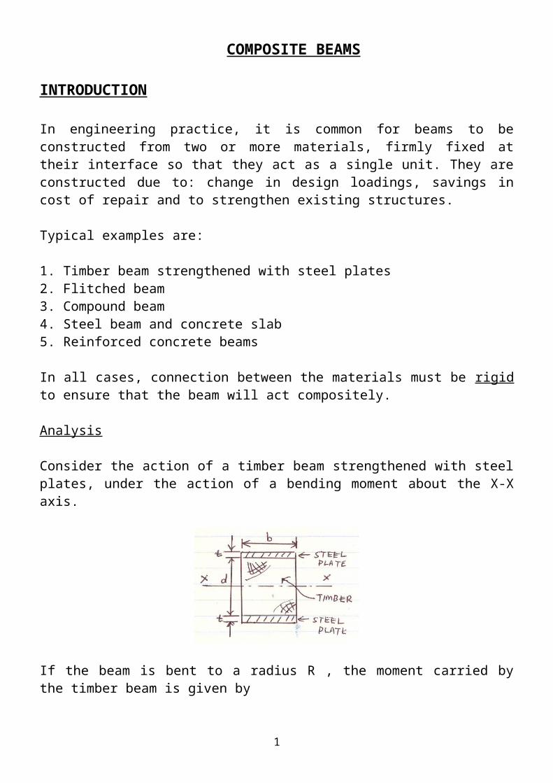
Consider the action of a timber beam strengthened with steel plates, under the action of a bending moment about the X-X axis.
If the beam is bent to a radius R , the moment carried by the timber beam is given by
Mt = Et I tR
If the connection between the timber and steel plates is rigid, the plates also bent to the same radius R, the moment carried by the steel is
Ms = Es I sR
1
Total moment of composite beam, Mcomp = Mt + Ms
= 1R (EtIt + EsIs)
or Mcomp = 1R (EI)comp where EI = flexural rigidity
rearranging, (EI)comp = Et ( It +
EsEt Is ) ……………….. Eqn. 1
From Eqn. 1, if Is is multiplied by m = (modular ratio), we can treat the composite beam as a wholly timber beam with an equivalent I value of:
I t' = ( It +
EsEt Is ) ……………………….. Eqn. 2,
where I t' = Transposed second moment of area (equivalent timber section)
It = 2nd moment of area (MOA) of timber beam about X-X
EsEt Is is the 2nd MOA of steel plates about X-X multiplied by modular ratio, m
EsEt Is = 2
EsEt [
bt3
12 + bt ( d2 +
t2 )2 ] …… Eqn. 3 (from INN = Ixx + Ah2 )
If b’ = b x
, then Eqn. 3 becomes
EsEt x Is = 2 [
b' t3
12 + b’t ( d2 +
t2 )2 ] ……. Eqn. 4
This is equivalent to considering the steel plates to be timber plates with an effective
width of b’ = b x
* - To transform a strong material to a weaker one, increases the effective width (> 1)
t
s
EE
t
s
EE
t
s
EE
2
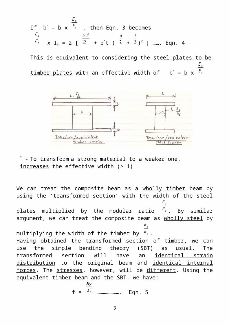
We can treat the composite beam as a wholly timber beam by using the ‘transformed
section’ with the width of the steel plates multiplied by the modular ratio
EsEt . By similar
argument, we can treat the composite beam as wholly steel by multiplying the width of the
timber by
EtEs .
Having obtained the transformed section of timber, we can use the simple bending theory (SBT) as usual. The transformed section will have an identical strain distribution to the original beam and identical internal forces. The stresses, however, will be different. Using the equivalent timber beam and the SBT, we have:
f =
MyI t'
…………………. Eqn. 5where I t
' = Transposed second moment of area , f = equivalent timber stress.
Any stresses obtained using Eqn. 5 will be equivalent timber stresses. If actual steel stress
is required, multiply the equivalent timber stress by
EtEs , i.e fs = f .
EtEs
Note:
The material which is stiff (steel) will always have a higher stress at any level than the less stiff material (timber) and vice-versa.
Example 1
A composite beam is subjected to a positive bending moment of 4 kNm. Determine the maximum stresses of the two materials if Et = 7 kN/mm2 and Es = 140 kN/mm2.
Transform the composite beam to equivalent timber section. The top section of the beam is not changed, the bottom section is changed by multiplying the width by modular ratio, m
where m =
EsEt =
1407 = 20
3
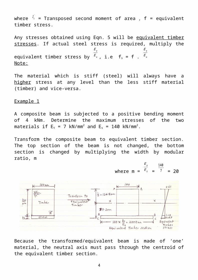
Because the transformed/equivalent beam is made of ‘one’ material, the neutral axis must pass through the centroid of the equivalent timber section.
1) Calculate y ,
Taking moments about A-A, y =
∑ M a
∑ AT = (100 x150 x75 )+(12x 2000 x156 )
(100 x150 )=(12 x2000 ) = 124.8 mm
2) Find I t', I t
' =
100 x124 .83
3 + 2000 x37 .23
3 - 1900 x25 . 23
3 = 88.98 x 10 6 mm 4
Using the bending equation,
i) Extreme top fibre, fAA =
MyI t'
= 4 x 10⁶ .(124 . 8)88 .98 x106 = 5.61 N/mm 2 (C)
ii) At the interface of two materials, fBB =
MyI t'
= 4 x 10⁶ .(25 .2 )88 . 98 x106 = 1.13 N/mm 2 (T)
iii) Extreme bottom fibre, fCC =
MyI t'
= 4 x 10⁶ .(37 .2)88 . 98 x106 = 1.67 N/mm 2 (T)
Stresses in the original beam are the same as the equivalent timber for timber only. Therefore for timber, they are the actual stresses.
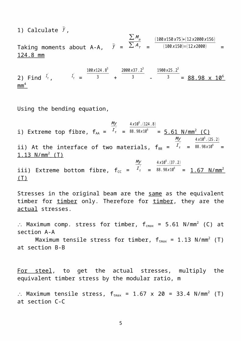
Maximum comp. stress for timber, fcmax = 5.61 N/mm2 (C) at section A-A Maximum tensile stress for timber, ftmax = 1.13 N/mm2 (T) at section B-B
For steel, to get the actual stresses, multiply the equivalent timber stress by the modular ratio, m
Maximum tensile stress, ftmax = 1.67 x 20 = 33.4 N/mm2 (T) at section C-C Minimum tensile stress, ftmin = 1.13 x 20 = 22.6 N/mm2 (T) at section B-B
4
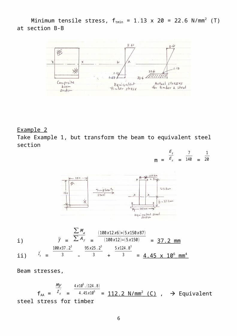
Example 2Take Example 1, but transform the beam to equivalent steel section
m =
EtEs =
7140 =
120
i) y =
∑ M a
∑ AT = (100 x12 x6 )+(5 x150 x87 )
(100 x12 )=(5 x150 ) = 37.2 mm
ii) I t' =
100 x37 .23
3 - 95 x25 . 23
3 + 5x 124 .83
3 = 4.45 x 10 6 mm 4
Beam stresses,
fAA =
MyI t'
= 4 x 10⁶ .(124 .8)
4 .45 x 106 = 112.2 N/mm 2 (C) , Equivalent steel stress for timber
fBB =
MyI t'
= 4 x 10⁶ .(25 .2 )
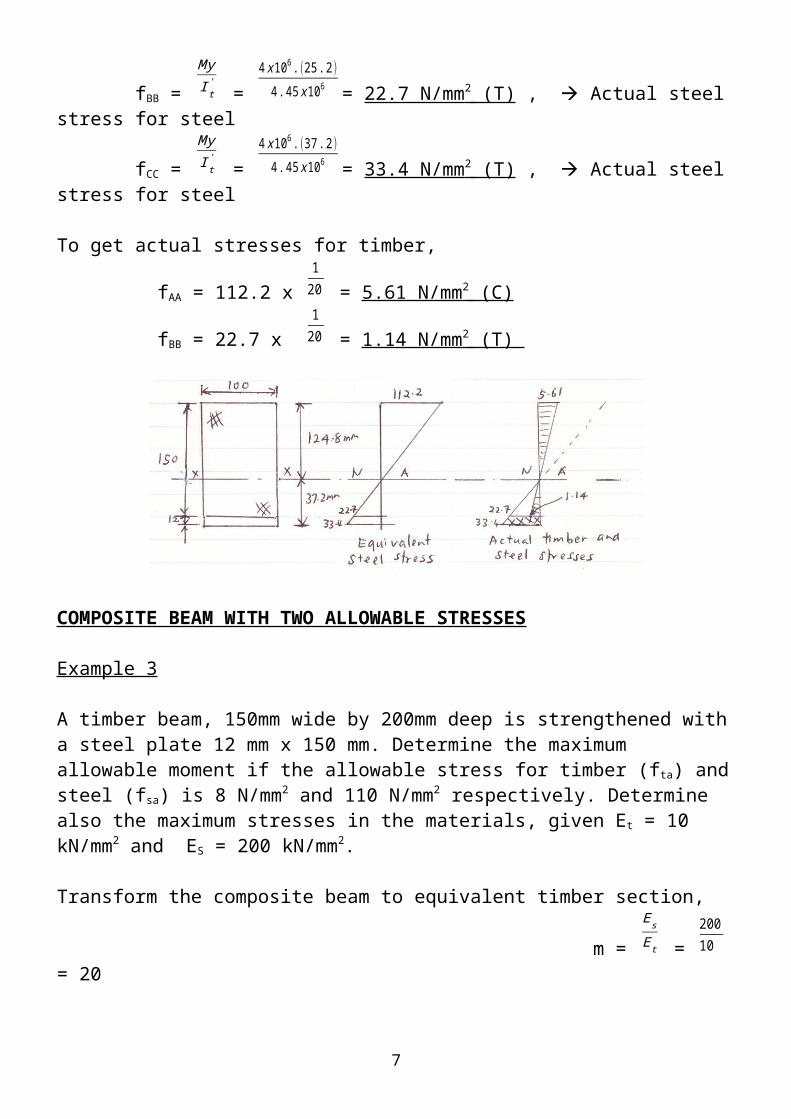
4 . 45 x106 = 22.7 N/mm 2 (T) , Actual steel stress for steel
fCC =
MyI t'
= 4 x 10⁶ .(37 . 2)
4 .45 x106 = 33.4 N/mm 2 (T) , Actual steel stress for steel
To get actual stresses for timber,
fAA = 112.2 x 1
20 = 5.61 N/mm 2 (C)
fBB = 22.7 x 1
20 = 1.14 N/mm 2 (T)
5
COMPOSITE BEAM WITH TWO ALLOWABLE STRESSES
Example 3
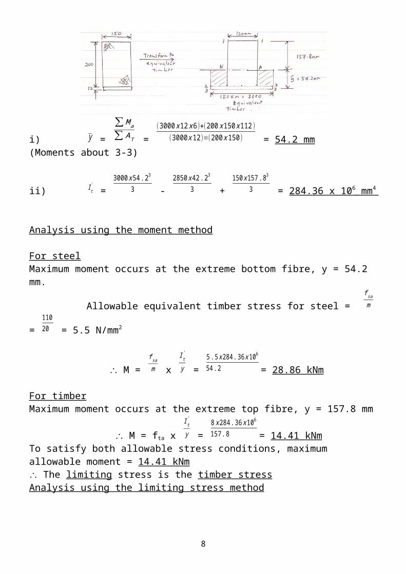
A timber beam, 150mm wide by 200mm deep is strengthened with a steel plate 12 mm x 150 mm. Determine the maximum allowable moment if the allowable stress for timber (fta) and steel (fsa) is 8 N/mm2 and 110 N/mm2 respectively. Determine also the maximum stresses in the materials, given Et = 10 kN/mm2 and ES = 200 kN/mm2.
Transform the composite beam to equivalent timber section,
m =
EsEt =
20010 = 20
i) y =
∑ M a
∑ AT = (3000 x12 x6 )+(200 x150 x112 )
(3000 x 12)=(200 x 150) = 54.2 mm (Moments about 3-3)
ii) I t' =
3000 x54 . 23
3 - 2850 x 42.23
3 + 150 x157 . 83
3 = 284.36 x 10 6 mm 4
Analysis using the moment method
For steelMaximum moment occurs at the extreme bottom fibre, y = 54.2 mm.
Allowable equivalent timber stress for steel = f sam =
11020 = 5.5 N/mm2
6
M = f sam x
I t'
y = 5.5 x284 .36 x106
54 .2 = 28.86 kNm
For timberMaximum moment occurs at the extreme top fibre, y = 157.8 mm
M = fta x I t'
y = 8 x284 . 36 x106
157 .8 = 14.41 kNmTo satisfy both allowable stress conditions, maximum allowable moment = 14.41 kNm The limiting stress is the timber stressAnalysis using the limiting stress method
Assume that the steel stress is limiting, y = 54.2 mm, and the allowable equivalent timber stress for steel = 5.5 N/mm2,
The maximum timber stress occurs at the extreme top fibre, y = 157.8 mm,
ft = 157 . 854 . 2 x 5.5 = 16 N/mm2
> fta of 8 N/mm2
The limiting stress is the allowable timber stress i.e maximum timber stress at the extreme top fibre =8 N/mm2
the equivalent timber stress for steel at the extreme bottom fibre,
fse = 54 . 2157 . 8 x 8 = 2.75 N/mm2
actual steel stress, fs = 2.75 x 20 = 55 N/mm2
< fsa (110 N/mm2) O.K
Stresses
Timber, Maximum compressive stress = 8 N/mm2 at section 1-1
Max. tensile stress = 42 . 2157 . 8 x 8 = 2.14 N/mm2 at section 2-2
7
Steel, Actual tensile stress at 2-2, fs2-2 = 2.14 x m (20) = 42.8 N/mm2 < fsa (110 N/mm2) O.K
Equivalent timber stress for steel at 3-3, fse3-3 = 54 . 2157 . 8 x 8 = 2.75 N/mm2
Actual steel tensile stress at 3-3, fs3-3 = 2.75 x m (20) = 55 N/mm2 < fsa (110 N/mm2) O.K
8