Embed Size (px)
Citation preview
©
L
T
© 2013 Cisco and
Lab – Te
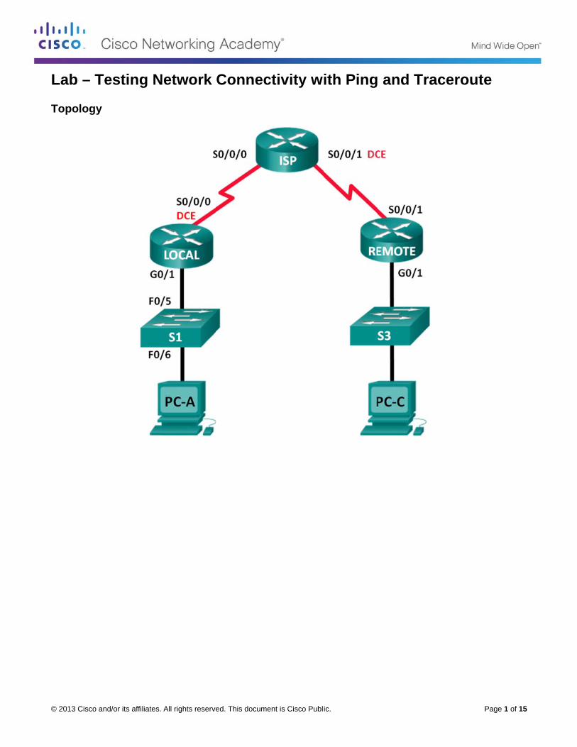
Topology
d/or its affiliates.
esting N
All rights reserve
Network
ed. This docume
Connec
ent is Cisco Publi
ctivity wi
ic.
ith Ping and Tra
P
aceroute
Page 1 of 15
e
Lab – Testing Network Connectivity with Ping and Traceroute
© 2013 Cisco and/or its affiliates. All rights reserved. This document is Cisco Public. Page 2 of 15
Addressing Table
Device Interface IP Address Subnet Mask Default Gateway
LOCAL G0/1 192.168.1.1 255.255.255.0 N/A
S0/0/0 (DCE) 10.1.1.1 255.255.255.252 N/A
ISP S0/0/0 10.1.1.2 255.255.255.252 N/A
S0/0/1 (DCE) 10.2.2.2 255.255.255.252 N/A
REMOTE G0/1 192.168.3.1 255.255.255.0 N/A
S0/0/1 10.2.2.1 255.255.255.252 N/A
S1 VLAN 1 192.168.1.11 255.255.255.0 192.168.1.1
S3 VLAN 1 192.168.3.11 255.255.255.0 192.168.3.1
PC-A NIC 192.168.1.3 255.255.255.0 192.168.1.1
PC-C NIC 192.168.3.3 255.255.255.0 192.168.3.1
Objectives
Part 1: Build and Configure the Network
Cable the network.
Configure the PCs.
Configure the routers.
Configure the switches.
Part 2: Use Ping Command for Basic Network Testing
Use ping from a PC.
Use ping from Cisco devices.
Part 3: Use Tracert and Traceroute Commands for Basic Network Testing
Use tracert from a PC.
Use traceroute from Cisco devices.
Part 4: Troubleshoot the Topology
Background / Scenario
Ping and traceroute are two tools that are indispensable when testing TCP/IP network connectivity. Ping is a network administration utility used to test the reachability of a device on an IP network. This utility also measures the round-trip time for messages sent from the originating host to a destination computer. The ping utility is available on Windows, Unix-like operating systems (OS), and the Cisco Internetwork Operating System (IOS).
The traceroute utility is a network diagnostic tool for displaying the route and measuring the transit delays of packets travelling an IP network. The tracert utility is available on Windows, and a similar utility, traceroute, is available on Unix-like OS and Cisco IOS.
In this lab, the ping and traceroute commands are examined and command options are explored to modify the command behavior. Cisco devices and PCs are used in this lab for command exploration. Cisco routers
Lab – Testing Network Connectivity with Ping and Traceroute
© 2013 Cisco and/or its affiliates. All rights reserved. This document is Cisco Public. Page 3 of 15
will use Enhanced Interior Gateway Routing Protocol (EIGRP) to route packets between networks. The necessary Cisco device configurations are provided in this lab.
Note: The routers used with CCNA hands-on labs are Cisco 1941 Integrated Services Routers (ISRs) with Cisco IOS Release 15.2(4)M3 (universalk9 image). The switches used are Cisco Catalyst 2960s with Cisco IOS Release 15.0(2) (lanbasek9 image). Other routers, switches and Cisco IOS versions can be used. Depending on the model and Cisco IOS version, the commands available and output produced might vary from what is shown in the labs. Refer to the Router Interface Summary Table at the end of this lab for the correct interface identifiers.
Note: Make sure that the routers and switches have been erased and have no startup configurations. If you are unsure, contact your instructor.
Required Resources
3 Routers (Cisco 1941 with Cisco IOS Release 15.2(4)M3 universal image or comparable)
2 Switches (Cisco 2960 with Cisco IOS Release 15.0(2) lanbasek9 image or comparable)
2 PCs (Windows 7, Vista, or XP with terminal emulation program, such as Tera Term)
Console cables to configure the Cisco IOS devices via the console ports
Ethernet and serial cables as shown in the topology
Part 1: Build and Configure the Network
In Part 1, you will set up the network in the topology and configure the PCs and Cisco devices. The initial configurations for the routers and switches are provided for your reference. In this topology, EIGRP is used to route packets between networks.
Step 1: Cable the network as shown in the topology.
Step 2: Erase the configurations on the routers and switches, and reload the devices.
Step 3: Configure PC IP addresses and default gateways according to the Addressing Table.
Step 4: Configure the LOCAL, ISP, and REMOTE routers using the initial configurations provided below.
At the switch or router global config mode prompt, copy and paste the configuration for each device. Save the configuration to startup-config.
Initial configurations for the LOCAL router:
hostname LOCAL
no ip domain-lookup
interface s0/0/0
ip address 10.1.1.1 255.255.255.252
clock rate 56000
no shutdown
interface g0/1
ip add 192.168.1.1 255.255.255.0
no shutdown
router eigrp 1
network 10.1.1.0 0.0.0.3
Lab – Testing Network Connectivity with Ping and Traceroute
© 2013 Cisco and/or its affiliates. All rights reserved. This document is Cisco Public. Page 4 of 15
network 192.168.1.0 0.0.0.255
no auto-summary
Initial configurations for ISP:
hostname ISP
no ip domain-lookup
interface s0/0/0
ip address 10.1.1.2 255.255.255.252
no shutdown
interface s0/0/1
ip add 10.2.2.2 255.255.255.252
clock rate 56000
no shutdown
router eigrp 1
network 10.1.1.0 0.0.0.3
network 10.2.2.0 0.0.0.3
no auto-summary
end
Initial configurations for REMOTE:
hostname REMOTE
no ip domain-lookup
interface s0/0/1
ip address 10.2.2.1 255.255.255.252
no shutdown
interface g0/1
ip add 192.168.3.1 255.255.255.0
no shutdown
router eigrp 1
network 10.2.2.0 0.0.0.3
network 192.168.3.0 0.0.0.255
no auto-summary
end
Step 5: Configure the S1 and S3 switches with the initial configurations.
Initial configurations for S1:
hostname S1
no ip domain-lookup
interface vlan 1
ip add 192.168.1.11 255.255.255.0
no shutdown
exit
ip default-gateway 192.168.1.1
end
Initial configurations for S3:
Lab – Testing Network Connectivity with Ping and Traceroute
© 2013 Cisco and/or its affiliates. All rights reserved. This document is Cisco Public. Page 5 of 15
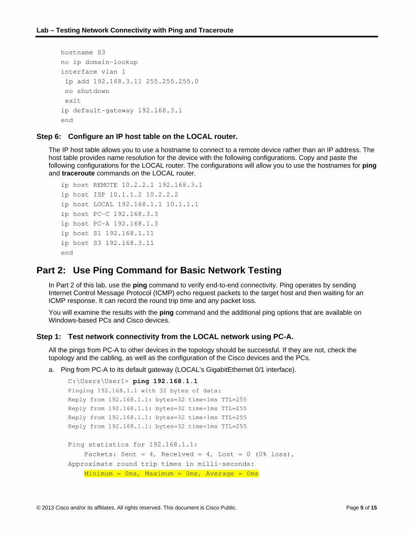
hostname S3
no ip domain-lookup
interface vlan 1
ip add 192.168.3.11 255.255.255.0
no shutdown
exit
ip default-gateway 192.168.3.1
end
Step 6: Configure an IP host table on the LOCAL router.
The IP host table allows you to use a hostname to connect to a remote device rather than an IP address. The host table provides name resolution for the device with the following configurations. Copy and paste the following configurations for the LOCAL router. The configurations will allow you to use the hostnames for ping and traceroute commands on the LOCAL router.
ip host REMOTE 10.2.2.1 192.168.3.1
ip host ISP 10.1.1.2 10.2.2.2
ip host LOCAL 192.168.1.1 10.1.1.1
ip host PC-C 192.168.3.3
ip host PC-A 192.168.1.3
ip host S1 192.168.1.11
ip host S3 192.168.3.11
end
Part 2: Use Ping Command for Basic Network Testing
In Part 2 of this lab, use the ping command to verify end-to-end connectivity. Ping operates by sending Internet Control Message Protocol (ICMP) echo request packets to the target host and then waiting for an ICMP response. It can record the round trip time and any packet loss.
You will examine the results with the ping command and the additional ping options that are available on Windows-based PCs and Cisco devices.
Step 1: Test network connectivity from the LOCAL network using PC-A.
All the pings from PC-A to other devices in the topology should be successful. If they are not, check the topology and the cabling, as well as the configuration of the Cisco devices and the PCs.
a. Ping from PC-A to its default gateway (LOCAL’s GigabitEthernet 0/1 interface).
C:\Users\User1> ping 192.168.1.1 Pinging 192.168.1.1 with 32 bytes of data:
Reply from 192.168.1.1: bytes=32 time<1ms TTL=255
Reply from 192.168.1.1: bytes=32 time<1ms TTL=255
Reply from 192.168.1.1: bytes=32 time<1ms TTL=255
Reply from 192.168.1.1: bytes=32 time<1ms TTL=255
Ping statistics for 192.168.1.1:
Packets: Sent = 4, Received = 4, Lost = 0 (0% loss),
Approximate round trip times in milli-seconds:
Minimum = 0ms, Maximum = 0ms, Average = 0ms

Lab – Testing Network Connectivity with Ping and Traceroute
© 2013 Cisco and/or its affiliates. All rights reserved. This document is Cisco Public. Page 6 of 15
In this example, four (4) ICMP requests, 32 bytes each, were sent and the responses were received in less than one millisecond with no packet loss. The transmission and reply time increases as the ICMP requests and responses are processed by more devices during the journey to and from the final destination.
b. From PC-A, ping the addresses listed in the following table and record the average round trip time and Time to Live (TTL).
Destination Average Round Trip Time (ms) TTL
192.168.1.1 (LOCAL)
192.168.1.11 (S1)
10.1.1.1 (LOCAL)
10.1.1.2 (ISP)
10.2.2.2 (ISP)
10.2.2.1 (REMOTE)
192.168.3.1 (REMOTE)
192.168.3.11 (S3)
192.168.3.3 (PC-C)
Notice the average round trip time to 192.168.3.3 (PC-C). The time increased because the ICMP requests were processed by three routers before PC-A received the reply from PC-C.
C:\Users\User1> ping 192.168.3.3 Pinging 192.168.3.3 with 32 bytes of data:
Reply from 192.168.3.3: bytes=32 time=41ms TTL=125
Reply from 192.168.3.3: bytes=32 time=41ms TTL=125
Reply from 192.168.3.3: bytes=32 time=40ms TTL=125
Reply from 192.168.3.3: bytes=32 time=41ms TTL=125
Ping statistics for 192.168.3.3:
Packets: Sent = 4, Received = 4, Lost = 0 (0% loss),
Approximate round trip times in milli-seconds:
Minimum = 40ms, Maximum = 41ms, Average = 40ms
Step 2: Use extended ping commands on a PC.
The default ping command sends four requests at 32 bytes each. It waits 4,000 milliseconds (4 seconds) for each response to be returned before displaying the “Request timed out” message. The ping command can be fine tuned for troubleshooting a network.
a. At the command prompt, type ping and press Enter.
C:\Users\User1> ping Usage: ping [-t] [-a] [-n count] [-l size] [-f] [-i TTL] [-v TOS]
[-r count] [-s count] [[-j host-list] | [-k host-list]]
[-w timeout] [-R] [-S srcaddr] [-4] [-6] target_name
Options:
-t Ping the specified host until stopped.

Lab – Testing Network Connectivity with Ping and Traceroute
© 2013 Cisco and/or its affiliates. All rights reserved. This document is Cisco Public. Page 7 of 15
To see statistics and continue - type Control-Break;
To stop - type Control-C.
-a Resolve addresses to hostnames.
-n count Number of echo requests to send.
-l size Send buffer size.
-f Set Don't Fragment flag in packet (IPv4-only).
-i TTL Time To Live.
-v TOS Type Of Service (IPv4-only. This setting has been deprecated
and has no effect on the type of service field in the IP Header).
-r count Record route for count hops (IPv4-only).
-s count Timestamp for count hops (IPv4-only).
-j host-list Loose source route along host-list (IPv4-only).
-k host-list Strict source route along host-list (IPv4-only).
-w timeout Timeout in milliseconds to wait for each reply.
-R Use routing header to test reverse route also (IPv6-only).
-S srcaddr Source address to use.
-4 Force using IPv4.
-6 Force using IPv6.
b. Using the –t option, ping PC-C to verify that PC-C is reachable.
C:\Users\User1> ping –t 192.168.3.3 Reply from 192.168.3.3: bytes=32 time=41ms TTL=125
Reply from 192.168.3.3: bytes=32 time=40ms TTL=125
To illustrate the results when a host is unreachable, disconnect the cable between the REMOTE router and the S3 switch, or shut down the GigabitEthernet 0/1 interface on the REMOTE router.
Reply from 192.168.3.3: bytes=32 time=41ms TTL=125
Reply from 192.168.1.3: Destination host unreachable.
Reply from 192.168.1.3: Destination host unreachable.
While the network is functioning correctly, the ping command can determine whether the destination responded and how long it took to receive a reply from the destination. If a network connectivity problem exists, the ping command displays an error message.
c. Reconnect the Ethernet cable or enable the GigabitEthernet interface on the REMOTE router (using the no shutdown command) before moving onto the next step. After about 30 seconds, the ping should be successful again.
Request timed out.
Request timed out.
Request timed out.
Request timed out.
Reply from 192.168.3.3: bytes=32 time=41ms TTL=125
Reply from 192.168.3.3: bytes=32 time=40ms TTL=125
d. Press Ctrl+C to stop the ping command.
Step 3: Test network connectivity from the LOCAL network using Cisco devices.
The ping command is also available on Cisco devices. In this step, the ping command is examined using the LOCAL router and the S1 switch.
a. Ping PC-C on the REMOTE network using the IP address of 192.168.3.3 from the LOCAL router.
LOCAL# ping 192.168.3.3

Lab – Testing Network Connectivity with Ping and Traceroute
© 2013 Cisco and/or its affiliates. All rights reserved. This document is Cisco Public. Page 8 of 15
Type escape sequence to abort.
Sending 5, 100-byte ICMP Echos to 192.168.3.3, timeout is 2 seconds:
!!!!!
Success rate is 100 percent (5/5), round-trip min/avg/max = 60/64/68 ms
The exclamation point (!) indicates that the ping was successful from the LOCAL router to PC-C. The round trip takes an average of 64 ms with no packet loss, as indicated by a 100% success rate.
b. Because a local host table was configured on the LOCAL router, you can ping PC-C on the REMOTE network using the hostname configured from the LOCAL router.
LOCAL# ping PC-C Type escape sequence to abort.
Sending 5, 100-byte ICMP Echos to 192.168.3.3, timeout is 2 seconds:
!!!!!
Success rate is 100 percent (5/5), round-trip min/avg/max = 60/63/64 ms
c. There are more options available for the ping command. At the CLI, type ping and press Enter. Input 192.168.3.3 or PC-C for the Target IP address. Press Enter to accept the default value for other options.
LOCAL# ping Protocol [ip]:
Target IP address: PC-C
Repeat count [5]:
Datagram size [100]:
Timeout in seconds [2]:
Extended commands [n]:
Sweep range of sizes [n]:
Type escape sequence to abort.
Sending 5, 100-byte ICMP Echos to 192.168.3.3, timeout is 2 seconds:
!!!!!
Success rate is 100 percent (5/5), round-trip min/avg/max = 60/63/64 ms
d. You can use an extended ping to observe when there is a network issue. Start the ping command to 192.168.3.3 with a repeat a count of 500. Then, disconnect the cable between the REMOTE router and the S3 switch or shut down the GigabitEthernet 0/1 interface on the REMOTE router.
Reconnect the Ethernet cable or enable the GigabitEthernet interface on the REMOTE router after the exclamation points (!) have replaced by the letter U and periods (.). After about 30 seconds, the ping should be successful again. Press Ctrl+Shift+6 to stop the ping command if desired.
LOCAL# ping Protocol [ip]:
Target IP address: 192.168.3.3
Repeat count [5]: 500
Datagram size [100]:
Timeout in seconds [2]:
Extended commands [n]:
Sweep range of sizes [n]:
Type escape sequence to abort.
Sending 500, 100-byte ICMP Echos to 192.168.3.3, timeout is 2 seconds:
!!!!!!!!!!!!!!!!!!!!!!!!!!!!!!!!!!!!!!!!!!!!!!!!!!!!!!!!!!!!!!!!!!!!!!
!!!!!!!!!!!!!!!!!!!!!!!!!!!!!!!!!!!!!!!!!!!!!!!!!!!!!!!!!!!!!!!!!!!!!!
!!!!!!!!!!!!!!!!!!!!!!!!!!!!!!!!!!!!!!!!!!!!!!!!!!!!!U................
....!!!!!!!!!!!!!!!!!!!!!!!!!!!!!!!!!!!!!!!!!!!!!!!!!!!!!!!!!!!!!!!!!!

Lab – Testing Network Connectivity with Ping and Traceroute
© 2013 Cisco and/or its affiliates. All rights reserved. This document is Cisco Public. Page 9 of 15
!!!!!!!!!!!!!!!!!!!!!!!!!!!!!!!!!!!!!!!!!!!!!!!!!!!!!!!!!!!!!!!!!!!!!!
!!!!!!!!!!!!!!!!!!!!!!!!!!!!!!!!!!!!!!!!!!!!!!!!!!!!!!!!!!!!!!!!!!!!!!
!!!!!!!!!!!!!!!!!!!!!!!!!!!!!!!!!!!!!!!!!!!!!!!!!!!!!!!!!!!!!!!!!!!!!!
!!!!!!!!!!
Success rate is 95 percent (479/500), round-trip min/avg/max = 60/63/72 ms
The letter U in the results indicates that a destination is unreachable. An error protocol data unit (PDU) was received by the LOCAL router. Each period (.) in the output indicates that the ping timed out while waiting for a reply from PC-C. In this example, 5% of the packets were lost during the simulated network outage.
Note: You can also use the following command for the same results:
LOCAL# ping 192.168.3.3 repeat 500
or
LOCAL# ping PC-C repeat 500
e. You can also test network connectivity with a switch. In this example, the S1 switch pings the S3 switch on the REMOTE network.
S1# ping 192.168.3.11 Type escape sequence to abort.
Sending 5, 100-byte ICMP Echos to 192.168.3.11, timeout is 2 seconds:
!!!!!
Success rate is 100 percent (5/5), round-trip min/avg/max = 67/67/68 ms
The ping command is extremely useful when troubleshooting network connectivity. However, ping cannot indicate the location of problem when a ping is not successful. The tracert (or traceroute) command can display network latency and path information.
Part 3: Use Tracert and Traceroute Commands for Basic Network Testing
The commands for tracing routes can be found on PCs and network devices. For a Windows-based PC, the tracert command uses ICMP messages to trace the path to the final destination. The traceroute command utilizes the User Datagram Protocol (UDP) datagrams for tracing routes to the final destination for Cisco devices and other Unix-like PCs.
In Part 3, you will examine the traceroute commands and determine the path that a packet travels to its final destination. You will use the tracert command from the Windows PCs and the traceroute command from the Cisco devices. You will also examine the options that are available for fine tuning the traceroute results.
Step 1: Use the tracert command from PC-A to PC-C.
a. At the command prompt, type tracert 192.168.3.3.
C:\Users\User1> tracert 192.168.3.3 Tracing route to PC-C [192.168.3.3]
Over a maximum of 30 hops:
1 <1 ms <1 ms <1 ms 192.168.1.1
2 24 ms 24 ms 24 ms 10.1.1.2
3 48 ms 48 ms 48 ms 10.2.2.1
4 59 ms 59 ms 59 ms PC-C [192.168.3.3]
Trace complete.

Lab – Testing Network Connectivity with Ping and Traceroute
© 2013 Cisco and/or its affiliates. All rights reserved. This document is Cisco Public. Page 10 of 15
The tracert results indicates the path from PC-A to PC-C is from PC-A to LOCAL to ISP to REMOTE to PC-C. The path to PC-C traveled through three router hops to the final destination of PC-C.
Step 2: Explore additional options for the tracert command.
a. At the command prompt, type tracert and press Enter.
C:\Users\User1> tracert
Usage: tracert [-d] [-h maximum_hops] [-j host-list] [-w timeout]
[-R] [-S srcaddr] [-4] [-6] target_name
Options:
-d Do not resolve addresses to hostnames.
-h maximum_hops Maximum number of hops to search for target.
-j host-list Loose source route along host-list (IPv4-only).
-w timeout Wait timeout milliseconds for each reply.
-R Trace round-trip path (IPv6-only).
-S srcaddr Source address to use (IPv6-only).
-4 Force using IPv4.
-6 Force using IPv6.
b. Use the -d option. Notice that the IP address of 192.168.3.3 is not resolved as PC-C.
C:\Users\User1> tracert –d 192.168.3.3 Tracing route to 192.168.3.3 over a maximum of 30 hops:
1 <1 ms <1 ms <1 ms 192.168.1.1
2 24 ms 24 ms 24 ms 10.1.1.2
3 48 ms 48 ms 48 ms 10.2.2.1
4 59 ms 59 ms 59 ms 192.168.3.3
Trace complete.
Step 3: Use the traceroute command from the LOCAL router to PC-C.
a. At the command prompt, type traceroute 192.168.3.3 or traceroute PC-C on the LOCAL router. The hostnames are resolved because a local IP host table was configured on the LOCAL router.
LOCAL# traceroute 192.168.3.3 Type escape sequence to abort.
Tracing the route to PC-C (192.168.3.3)
VRF info: (vrf in name/id, vrf out name/id)
1 ISP (10.1.1.2) 16 msec 16 msec 16 msec
2 REMOTE (10.2.2.1) 28 msec 32 msec 28 msec
3 PC-C (192.168.3.3) 32 msec 28 msec 32 msec
LOCAL# traceroute PC-C Type escape sequence to abort.
Tracing the route to PC-C (192.168.3.3)
VRF info: (vrf in name/id, vrf out name/id)
1 ISP (10.1.1.2) 16 msec 16 msec 16 msec
2 REMOTE (10.2.2.1) 28 msec 32 msec 28 msec

Lab – Testing Network Connectivity with Ping and Traceroute
© 2013 Cisco and/or its affiliates. All rights reserved. This document is Cisco Public. Page 11 of 15
3 PC-C (192.168.3.3) 32 msec 32 msec 28 msec
Step 4: Use the traceroute command from the S1 switch to PC-C.
a. On the S1 switch, type traceroute 192.168.3.3. The hostnames are not displayed in the traceroute results because a local IP host table was not configured on this switch.
S1# traceroute 192.168.3.3 Type escape sequence to abort.
Tracing the route to 192.168.3.3
VRF info: (vrf in name/id, vrf out name/id)
1 192.168.1.1 1007 msec 0 msec 0 msec
2 10.1.1.2 17 msec 17 msec 16 msec
3 10.2.2.1 34 msec 33 msec 26 msec
4 192.168.3.3 33 msec 34 msec 33 msec
The traceroute command has additional options. You can use the ? or just press Enter after typing traceroute at the prompt to explore these options.
The following link provides more information regarding the ping and traceroute commands for a Cisco device:
http://www.cisco.com/en/US/products/sw/iosswrel/ps1831/products_tech_note09186a00800a6057.shtml
Part 4: Troubleshoot the Topology
Step 1: Erase the configurations on the REMOTE router.
Step 2: Reload the REMOTE router.
Step 3: Copy and paste the following configuration into the REMOTE router.
hostname REMOTE
no ip domain-lookup
interface s0/0/1
ip address 10.2.2.1 255.255.255.252
no shutdown
interface g0/1
ip add 192.168.8.1 255.255.255.0
no shutdown
router eigrp 1
network 10.2.2.0 0.0.0.3
network 192.168.3.0 0.0.0.255
no auto-summary
end
Step 4: From the LOCAL network, use ping and tracert or traceroute commands to troubleshoot and correct the problem on the REMOTE network.
a. Use the ping and tracert commands from PC-A.
Lab – Testing Network Connectivity with Ping and Traceroute
© 2013 Cisco and/or its affiliates. All rights reserved. This document is Cisco Public. Page 12 of 15
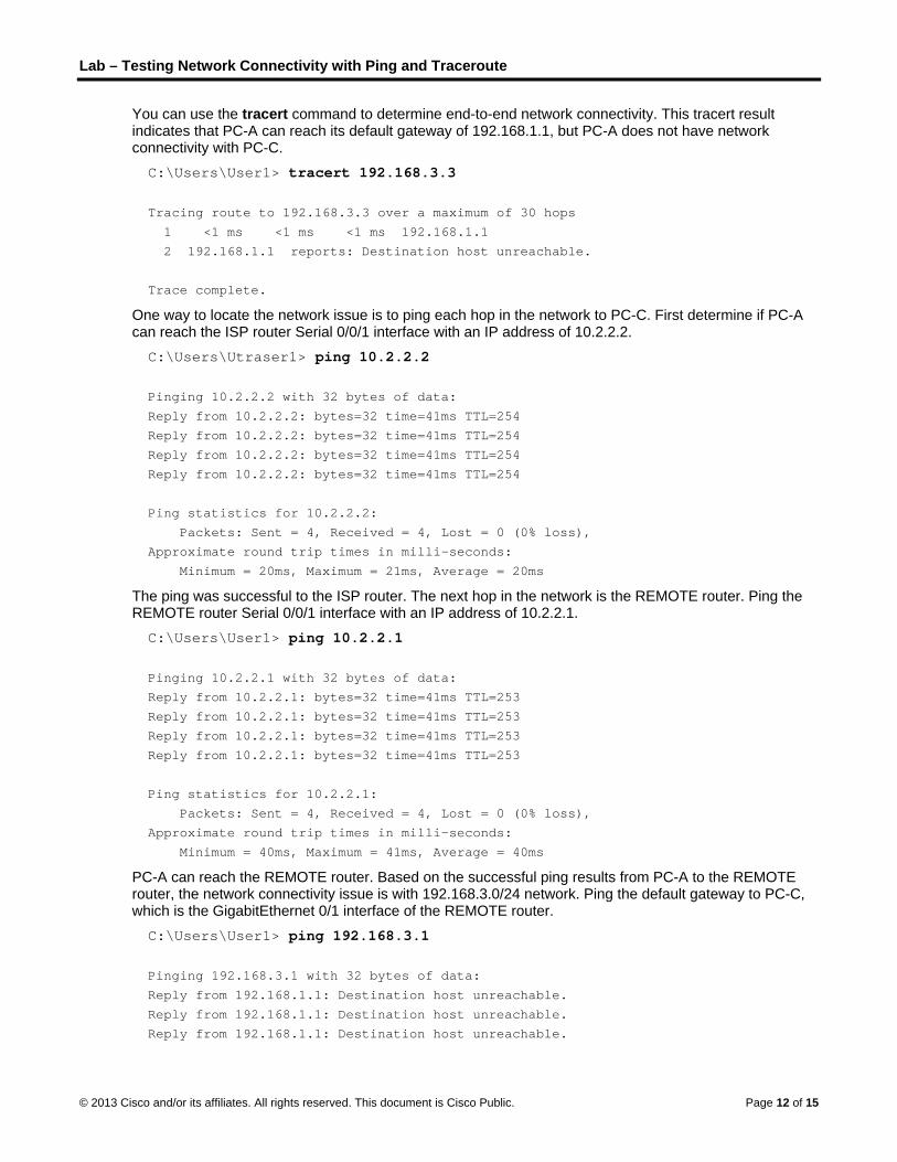
You can use the tracert command to determine end-to-end network connectivity. This tracert result indicates that PC-A can reach its default gateway of 192.168.1.1, but PC-A does not have network connectivity with PC-C.
C:\Users\User1> tracert 192.168.3.3
Tracing route to 192.168.3.3 over a maximum of 30 hops
1 <1 ms <1 ms <1 ms 192.168.1.1
2 192.168.1.1 reports: Destination host unreachable.
Trace complete.
One way to locate the network issue is to ping each hop in the network to PC-C. First determine if PC-A can reach the ISP router Serial 0/0/1 interface with an IP address of 10.2.2.2.
C:\Users\Utraser1> ping 10.2.2.2
Pinging 10.2.2.2 with 32 bytes of data:
Reply from 10.2.2.2: bytes=32 time=41ms TTL=254
Reply from 10.2.2.2: bytes=32 time=41ms TTL=254
Reply from 10.2.2.2: bytes=32 time=41ms TTL=254
Reply from 10.2.2.2: bytes=32 time=41ms TTL=254
Ping statistics for 10.2.2.2:
Packets: Sent = 4, Received = 4, Lost = 0 (0% loss),
Approximate round trip times in milli-seconds:
Minimum = 20ms, Maximum = 21ms, Average = 20ms
The ping was successful to the ISP router. The next hop in the network is the REMOTE router. Ping the REMOTE router Serial 0/0/1 interface with an IP address of 10.2.2.1.
C:\Users\User1> ping 10.2.2.1
Pinging 10.2.2.1 with 32 bytes of data:
Reply from 10.2.2.1: bytes=32 time=41ms TTL=253
Reply from 10.2.2.1: bytes=32 time=41ms TTL=253
Reply from 10.2.2.1: bytes=32 time=41ms TTL=253
Reply from 10.2.2.1: bytes=32 time=41ms TTL=253
Ping statistics for 10.2.2.1:
Packets: Sent = 4, Received = 4, Lost = 0 (0% loss),
Approximate round trip times in milli-seconds:
Minimum = 40ms, Maximum = 41ms, Average = 40ms
PC-A can reach the REMOTE router. Based on the successful ping results from PC-A to the REMOTE router, the network connectivity issue is with 192.168.3.0/24 network. Ping the default gateway to PC-C, which is the GigabitEthernet 0/1 interface of the REMOTE router.
C:\Users\User1> ping 192.168.3.1
Pinging 192.168.3.1 with 32 bytes of data:
Reply from 192.168.1.1: Destination host unreachable.
Reply from 192.168.1.1: Destination host unreachable.
Reply from 192.168.1.1: Destination host unreachable.
Lab – Testing Network Connectivity with Ping and Traceroute
© 2013 Cisco and/or its affiliates. All rights reserved. This document is Cisco Public. Page 13 of 15
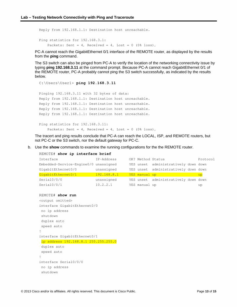
Reply from 192.168.1.1: Destination host unreachable.
Ping statistics for 192.168.3.1:
Packets: Sent = 4, Received = 4, Lost = 0 (0% loss),
PC-A cannot reach the GigabitEthernet 0/1 interface of the REMOTE router, as displayed by the results from the ping command.
The S3 switch can also be pinged from PC-A to verify the location of the networking connectivity issue by typing ping 192.168.3.11 at the command prompt. Because PC-A cannot reach GigabitEthernet 0/1 of the REMOTE router, PC-A probably cannot ping the S3 switch successfully, as indicated by the results below.
C:\Users\User1> ping 192.168.3.11
Pinging 192.168.3.11 with 32 bytes of data:
Reply from 192.168.1.1: Destination host unreachable.
Reply from 192.168.1.1: Destination host unreachable.
Reply from 192.168.1.1: Destination host unreachable.
Reply from 192.168.1.1: Destination host unreachable.
Ping statistics for 192.168.3.11:
Packets: Sent = 4, Received = 4, Lost = 0 (0% loss),
The tracert and ping results conclude that PC-A can reach the LOCAL, ISP, and REMOTE routers, but not PC-C or the S3 switch, nor the default gateway for PC-C.
b. Use the show commands to examine the running configurations for the the REMOTE router.
REMOTE# show ip interface brief Interface IP-Address OK? Method Status Protocol
Embedded-Service-Engine0/0 unassigned YES unset administratively down down
GigabitEthernet0/0 unassigned YES unset administratively down down
GigabitEthernet0/1 192.168.8.1 YES manual up up
Serial0/0/0 unassigned YES unset administratively down down
Serial0/0/1 10.2.2.1 YES manual up up
REMOTE# show run <output omitted>
interface GigabitEthernet0/0
no ip address
shutdown
duplex auto
speed auto
!
interface GigabitEthernet0/1
ip address 192.168.8.1 255.255.255.0
duplex auto
speed auto
!
interface Serial0/0/0
no ip address
shutdown
Lab – Testing Network Connectivity with Ping and Traceroute
© 2013 Cisco and/or its affiliates. All rights reserved. This document is Cisco Public. Page 14 of 15
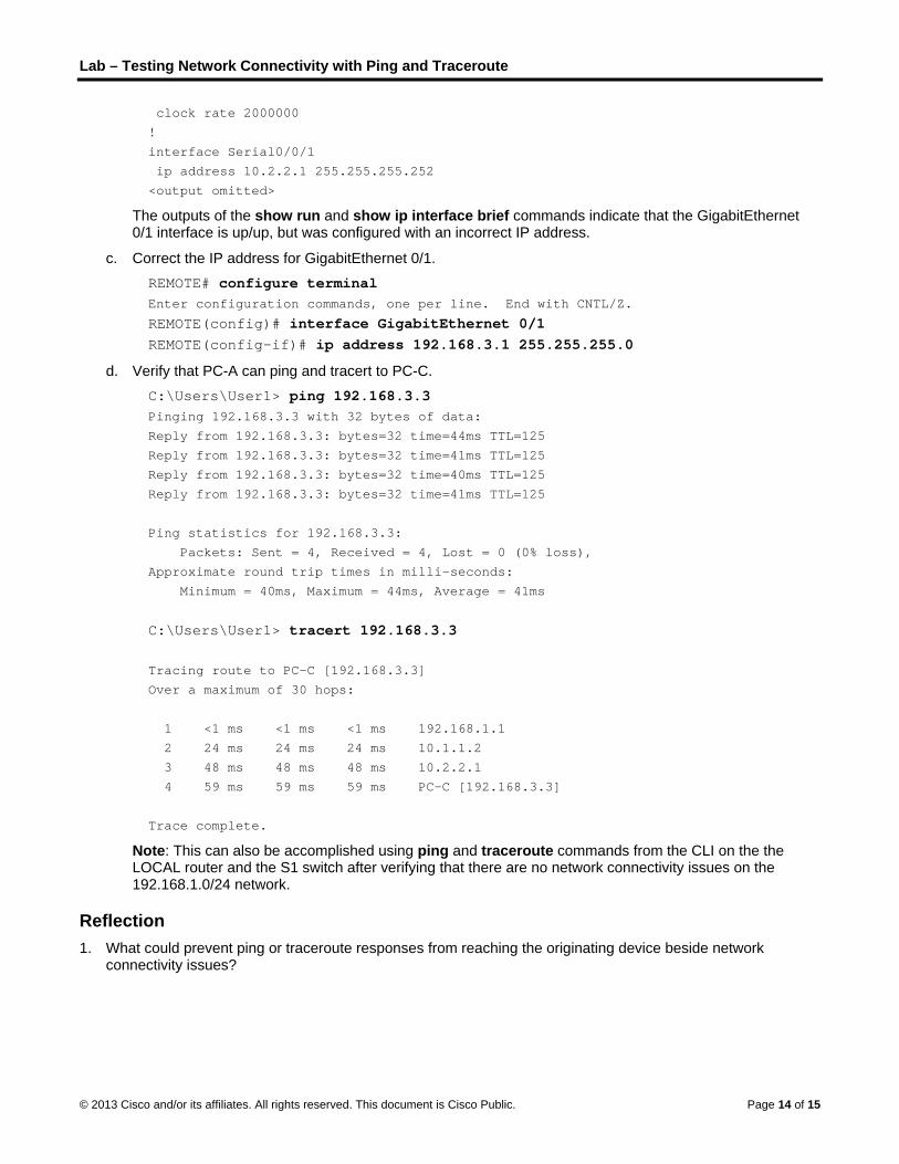
clock rate 2000000
!
interface Serial0/0/1
ip address 10.2.2.1 255.255.255.252
<output omitted>
The outputs of the show run and show ip interface brief commands indicate that the GigabitEthernet 0/1 interface is up/up, but was configured with an incorrect IP address.
c. Correct the IP address for GigabitEthernet 0/1.
REMOTE# configure terminal Enter configuration commands, one per line. End with CNTL/Z.
REMOTE(config)# interface GigabitEthernet 0/1
REMOTE(config-if)# ip address 192.168.3.1 255.255.255.0
d. Verify that PC-A can ping and tracert to PC-C.
C:\Users\User1> ping 192.168.3.3 Pinging 192.168.3.3 with 32 bytes of data:
Reply from 192.168.3.3: bytes=32 time=44ms TTL=125
Reply from 192.168.3.3: bytes=32 time=41ms TTL=125
Reply from 192.168.3.3: bytes=32 time=40ms TTL=125
Reply from 192.168.3.3: bytes=32 time=41ms TTL=125
Ping statistics for 192.168.3.3:
Packets: Sent = 4, Received = 4, Lost = 0 (0% loss),
Approximate round trip times in milli-seconds:
Minimum = 40ms, Maximum = 44ms, Average = 41ms
C:\Users\User1> tracert 192.168.3.3
Tracing route to PC-C [192.168.3.3]
Over a maximum of 30 hops:
1 <1 ms <1 ms <1 ms 192.168.1.1
2 24 ms 24 ms 24 ms 10.1.1.2
3 48 ms 48 ms 48 ms 10.2.2.1
4 59 ms 59 ms 59 ms PC-C [192.168.3.3]
Trace complete.
Note: This can also be accomplished using ping and traceroute commands from the CLI on the the LOCAL router and the S1 switch after verifying that there are no network connectivity issues on the 192.168.1.0/24 network.
Reflection
1. What could prevent ping or traceroute responses from reaching the originating device beside network connectivity issues?

Lab – Testing Network Connectivity with Ping and Traceroute
© 2013 Cisco and/or its affiliates. All rights reserved. This document is Cisco Public. Page 15 of 15
2. If you ping a non-existent address on the remote network, such as 192.168.3.4, what is the message displayed by the ping command? What does this mean? If you ping a valid host address and receive this response, what should you check?
3. If you ping an address that does not exist in any network in your topology, such as 192.168.5.3, from a Windows-based PC, what is the message displayed by the ping command? What does this message indicate?
Router Interface Summary Table
Router Interface Summary
Router Model Ethernet Interface #1 Ethernet Interface #2 Serial Interface #1 Serial Interface #2
1800 Fast Ethernet 0/0 (F0/0)
Fast Ethernet 0/1 (F0/1)
Serial 0/0/0 (S0/0/0) Serial 0/0/1 (S0/0/1)
1900 Gigabit Ethernet 0/0 (G0/0)
Gigabit Ethernet 0/1 (G0/1)
Serial 0/0/0 (S0/0/0) Serial 0/0/1 (S0/0/1)
2801 Fast Ethernet 0/0 (F0/0)
Fast Ethernet 0/1 (F0/1)
Serial 0/1/0 (S0/1/0) Serial 0/1/1 (S0/1/1)
2811 Fast Ethernet 0/0 (F0/0)
Fast Ethernet 0/1 (F0/1)
Serial 0/0/0 (S0/0/0) Serial 0/0/1 (S0/0/1)
2900 Gigabit Ethernet 0/0 (G0/0)
Gigabit Ethernet 0/1 (G0/1)
Serial 0/0/0 (S0/0/0) Serial 0/0/1 (S0/0/1)
Note: To find out how the router is configured, look at the interfaces to identify the type of router and how many interfaces the router has. There is no way to effectively list all the combinations of configurations for each router class. This table includes identifiers for the possible combinations of Ethernet and Serial interfaces in the device. The table does not include any other type of interface, even though a specific router may contain one. An example of this might be an ISDN BRI interface. The string in parenthesis is the legal abbreviation that can be used in Cisco IOS commands to represent the interface.