Embed Size (px)
Citation preview
CI/SfB (29) Et6
June 2019
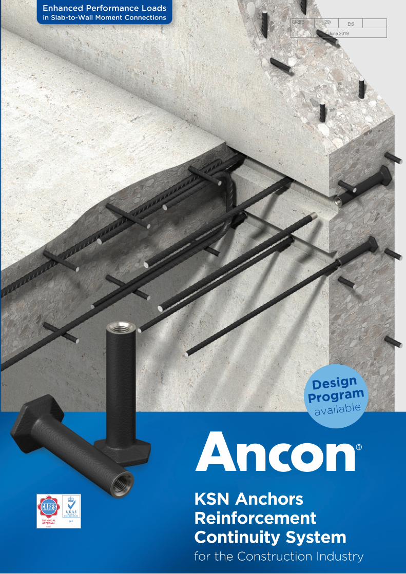
Enhanced Performance Loads in Slab-to-Wall Moment Connections
Design
Programavailable
TECHNICAL APPROVAL
5061
KSN Anchors Reinforcement Continuity Systemfor the Construction Industry
KSN Anchors Safer, faster, easier construction joints
System Components, Details for Specifying and Ordering 4-5
System Performance, Bottom Anchorage Options 6-7
Key Design Considerations 8
Anchor Selection Examples 9
Direct Tensile Concrete Characteristic Loads 10-11
Tensile Concrete Characteristic Loads in Moment Connections 12-14
Design Considerations - Reinforcement Details, Bottom Anchor Design Guidance, Ductility Requirements, Corners, Shear Checks 15-19
Installation Procedure and Guidance on Cutting Anchor Carrier 20-22
Other Ancon Products 23
Contents
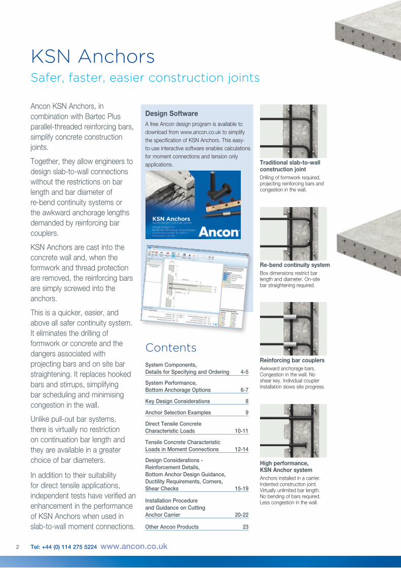
Ancon KSN Anchors, in combination with Bartec Plus parallel-threaded reinforcing bars, simplify concrete construction joints.
Together, they allow engineers to design slab-to-wall connections without the restrictions on bar length and bar diameter of re-bend continuity systems or the awkward anchorage lengths demanded by reinforcing bar couplers.
KSN Anchors are cast into the concrete wall and, when the formwork and thread protection are removed, the reinforcing bars are simply screwed into the anchors.
This is a quicker, easier, and above all safer continuity system. It eliminates the drilling of formwork or concrete and the dangers associated with projecting bars and on site bar straightening. It replaces hooked bars and stirrups, simplifying bar scheduling and minimising congestion in the wall.
Unlike pull-out bar systems, there is virtually no restriction on continuation bar length and they are available in a greater choice of bar diameters.
In addition to their suitability for direct tensile applications, independent tests have verified an enhancement in the performance of KSN Anchors when used in slab-to-wall moment connections.
Traditional slab-to-wall construction jointDrilling of formwork required, projecting reinforcing bars and congestion in the wall.
Re-bend continuity systemBox dimensions restrict bar length and diameter. On-site bar straightening required.
Reinforcing bar couplersAwkward anchorage bars. Congestion in the wall. No shear key. Individual coupler installation slows site progress.
2 Tel: +44 (0) 114 275 5224 www.ancon.co.uk
High performance, KSN Anchor systemAnchors installed in a carrier. Indented construction joint. Virtually unlimited bar length. No bending of bars required. Less congestion in the wall.
Design Software A free Ancon design program is available to download from www.ancon.co.uk to simplify the specification of KSN Anchors. This easy-to-use interactive software enables calculations for moment connections and tension only applications.
3
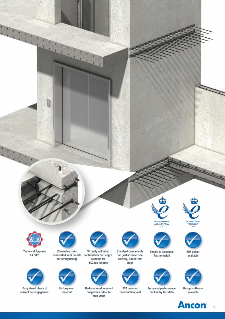
Eliminates risks associated with on-site
bar straightening
Virtually unlimited continuation bar length.
Suitable for EC2 lap lengths
Standard components for ‘just-in-time’ site delivery, direct from
stock
Easy visual check of correct bar engagement
Simple to schedule. Fast to install
No torqueing required
Reduces reinforcement congestion. Ideal for
thin walls
EC2 indented construction joint
Enhanced performance backed by test data
Design software available
BIM object available
Technical ApprovalTA 5061
TECHNICAL APPROVAL
5061
Ancon KSN Anchors
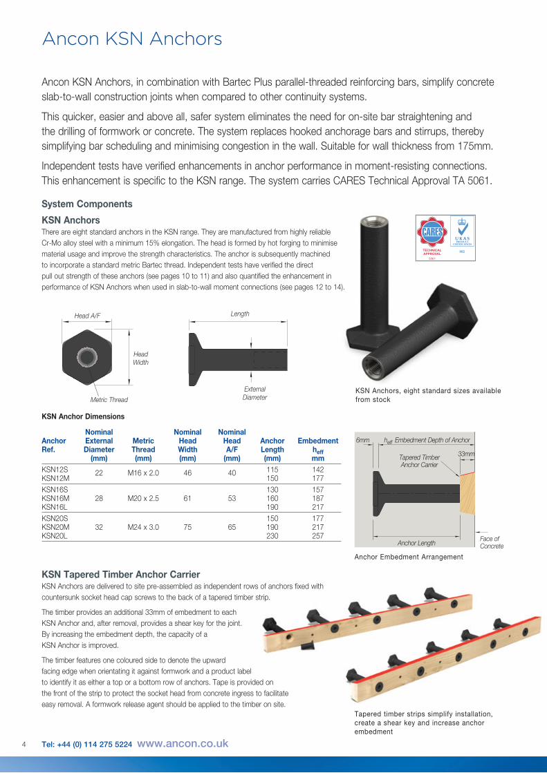
KSN Tapered Timber Anchor CarrierKSN Anchors are delivered to site pre-assembled as independent rows of anchors fixed with countersunk socket head cap screws to the back of a tapered timber strip.
The timber provides an additional 33mm of embedment to each KSN Anchor and, after removal, provides a shear key for the joint. By increasing the embedment depth, the capacity of a KSN Anchor is improved.
The timber features one coloured side to denote the upward facing edge when orientating it against formwork and a product label to identify it as either a top or a bottom row of anchors. Tape is provided on the front of the strip to protect the socket head from concrete ingress to facilitate easy removal. A formwork release agent should be applied to the timber on site.
4 Tel: +44 (0) 114 275 5224 www.ancon.co.uk
Ancon KSN Anchors, in combination with Bartec Plus parallel-threaded reinforcing bars, simplify concrete slab-to-wall construction joints when compared to other continuity systems.
This quicker, easier and above all, safer system eliminates the need for on-site bar straightening and the drilling of formwork or concrete. The system replaces hooked anchorage bars and stirrups, thereby simplifying bar scheduling and minimising congestion in the wall. Suitable for wall thickness from 175mm.
Independent tests have verified enhancements in anchor performance in moment-resisting connections. This enhancement is specific to the KSN range. The system carries CARES Technical Approval TA 5061.
External DiameterMetric Thread
Head A/F Length
Head Width
Nominal Nominal NominalAnchor External Metric Head Head Anchor EmbedmentRef. Diameter Thread Width A/F Length heff (mm) (mm) (mm) (mm) (mm) mmKSN12S 22 M16 x 2.0 46 40 115 142 KSN12M 150 177KSN16S 130 157 KSN16M 28 M20 x 2.5 61 53 160 187 KSN16L 190 217KSN20S 150 177 KSN20M 32 M24 x 3.0 75 65 190 217 KSN20L 230 257
KSN Anchor Dimensions
System Components
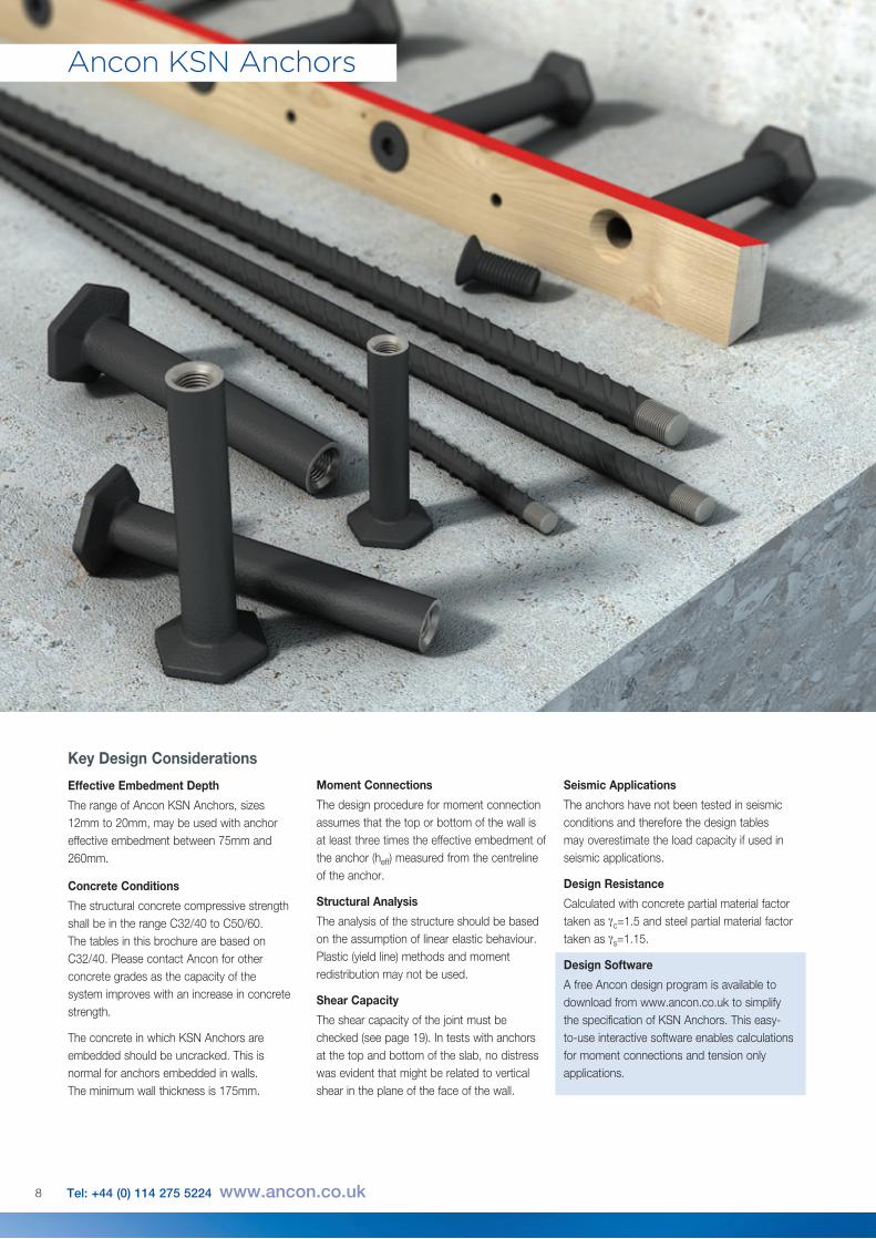
KSN Anchors There are eight standard anchors in the KSN range. They are manufactured from highly reliable Cr-Mo alloy steel with a minimum 15% elongation. The head is formed by hot forging to minimise material usage and improve the strength characteristics. The anchor is subsequently machined to incorporate a standard metric Bartec thread. Independent tests have verified the direct pull out strength of these anchors (see pages 10 to 11) and also quantified the enhancement in performance of KSN Anchors when used in slab-to-wall moment connections (see pages 12 to 14).
6mm
33mm
heff Embedment Depth of Anchor
Anchor LengthFace of Concrete
Tapered Timber Anchor Carrier
Anchor Embedment Arrangement
Tapered timber strips simplify installation, create a shear key and increase anchor embedment
KSN Anchors, eight standard sizes available from stock
TECHNICAL APPROVAL
5061
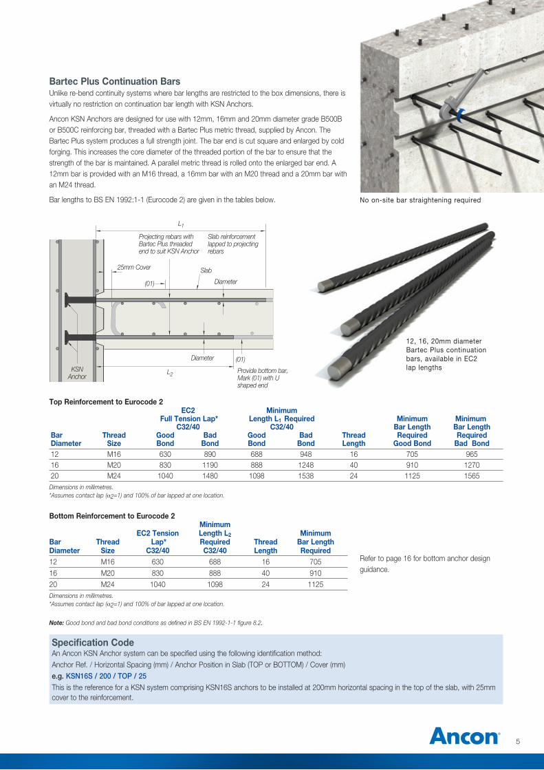
Bartec Plus Continuation BarsUnlike re-bend continuity systems where bar lengths are restricted to the box dimensions, there is virtually no restriction on continuation bar length with KSN Anchors.
Ancon KSN Anchors are designed for use with 12mm, 16mm and 20mm diameter grade B500B or B500C reinforcing bar, threaded with a Bartec Plus metric thread, supplied by Ancon. The Bartec Plus system produces a full strength joint. The bar end is cut square and enlarged by cold forging. This increases the core diameter of the threaded portion of the bar to ensure that the strength of the bar is maintained. A parallel metric thread is rolled onto the enlarged bar end. A 12mm bar is provided with an M16 thread, a 16mm bar with an M20 thread and a 20mm bar with an M24 thread.
Bar lengths to BS EN 1992:1-1 (Eurocode 2) are given in the tables below.
Specification Code An Ancon KSN Anchor system can be specified using the following identification method:Anchor Ref. / Horizontal Spacing (mm) / Anchor Position in Slab (TOP or BOTTOM) / Cover (mm)e.g. KSN16S / 200 / TOP / 25This is the reference for a KSN system comprising KSN16S anchors to be installed at 200mm horizontal spacing in the top of the slab, with 25mm cover to the reinforcement.
5
EC2 Minimum Full Tension Lap* Length L1 Required Minimum Minimum C32/40 C32/40 Bar Length Bar LengthBar Thread Good Bad Good Bad Thread Required Required Diameter Size Bond Bond Bond Bond Length Good Bond Bad Bond 12 M16 630 890 688 948 16 705 965 16 M20 830 1190 888 1248 40 910 1270 20 M24 1040 1480 1098 1538 24 1125 1565Dimensions in millimetres. *Assumes contact lap (a2=1) and 100% of bar lapped at one location.
Minimum EC2 Tension Length L2 Minimum Bar Thread Lap* Required Thread Bar Length Diameter Size C32/40 C32/40 Length Required12 M16 630 688 16 70516 M20 830 888 40 91020 M24 1040 1098 24 1125Dimensions in millimetres. *Assumes contact lap (a2=1) and 100% of bar lapped at one location.
Top Reinforcement to Eurocode 2
Bottom Reinforcement to Eurocode 2
KSN Anchor
25mm Cover
Diameter
Diameter (01)
(01)
L2
L1
Slab
No on-site bar straightening required
12, 16, 20mm diameter Bartec Plus continuation bars, available in EC2 lap lengths
Slab reinforcement lapped to projecting rebars
Provide bottom bar, Mark (01) with U shaped end
Projecting rebars with Bartec Plus threaded end to suit KSN Anchor
Refer to page 16 for bottom anchor design guidance.
Note: Good bond and bad bond conditions as defined in BS EN 1992-1-1 figure 8.2.
Ancon KSN Anchors
6 Tel: +44 (0) 114 275 5224 www.ancon.co.uk
T
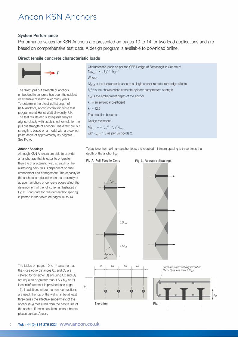
Fig B. Reduced SpacingsFig A. Full Tensile Cone
heff
Approx. 35˚
1.5heff
1.5heff
Characteristic loads as per the CEB Design of Fastenings in Concrete: N0
Rk,c = k1 . fck0.5 . heff
1.5
Where:
N0Rk,c is the tension resistance of a single anchor remote from edge effects
fck0.5 is the characteristic concrete cylinder compressive strength
heff is the embedment depth of the anchor
k1 is an empirical coefficient
k1 = 12.5
The equation becomes
Design resistance
N0Rd,c = k1 fck
0.5 . heff1.5/γm,c
with γm,c= 1.5 as per Eurocode 2.
Direct tensile concrete characteristic loads
The direct pull out strength of anchors embedded in concrete has been the subject of extensive research over many years. To determine the direct pull strength of KSN Anchors, Ancon commissioned a test programme at Heriot Watt University, UK. The test results and subsequent analysis aligned closely with established formula for the pull out strength of anchors. The direct pull out strength is based on a model with a break out prism angle of approximately 35 degrees. See Fig A.
System PerformancePerformance values for KSN Anchors are presented on pages 10 to 14 for two load applications and are based on comprehensive test data. A design program is available to download online.
Anchor SpacingsAlthough KSN Anchors are able to provide an anchorage that is equal to or greater than the characteristic yield strength of the reinforcing bars, this is dependent on their embedment and arrangement. The capacity of the anchors is reduced when the proximity of adjacent anchors or concrete edges affect the development of the full cone, as illustrated in Fig B. Load data for reduced anchor spacing is printed in the tables on pages 10 to 14.
The tables on pages 10 to 14 assume that the close edge distances Cx and Cy are catered for by either (1) ensuring Cx and Cy are equal to or greater than 1.5 x heff or (2) local reinforcement is provided (see page 15). In addition, where moment connections are used, the top of the wall shall be at least three times the effective embedment of the anchor (heff) measured from the centre line of the anchor. If these conditions cannot be met, please contact Ancon.
Cx
Cy
heff
Sx Sx Sx Local reinforcement required when Cx or Cy is less than 1.5heff
Elevation Plan
To achieve the maximum anchor load, the required minimum spacing is three times the depth of the anchor heff.
7
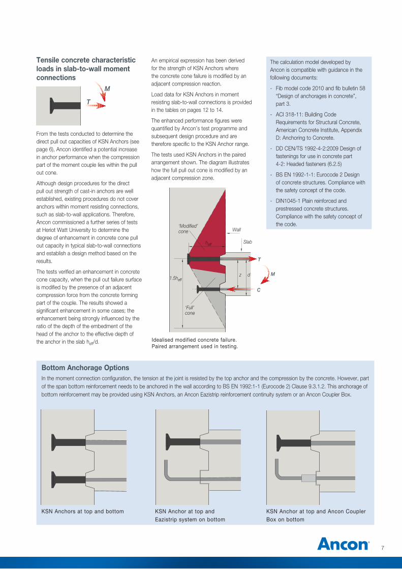
1.5heff
heff
Wall
Slab
T
C
z d M
From the tests conducted to determine the direct pull out capacities of KSN Anchors (see page 6), Ancon identified a potential increase in anchor performance when the compression part of the moment couple lies within the pull out cone.
Although design procedures for the direct pull out strength of cast-in anchors are well established, existing procedures do not cover anchors within moment resisting connections, such as slab-to-wall applications. Therefore, Ancon commissioned a further series of tests at Heriot Watt University to determine the degree of enhancement in concrete cone pull out capacity in typical slab-to-wall connections and establish a design method based on the results.
The tests verified an enhancement in concrete cone capacity, when the pull out failure surface is modified by the presence of an adjacent compression force from the concrete forming part of the couple. The results showed a significant enhancement in some cases; the enhancement being strongly influenced by the ratio of the depth of the embedment of the head of the anchor to the effective depth of the anchor in the slab heff/d. Idealised modified concrete failure.
Paired arrangement used in testing.
M
T
An empirical expression has been derived for the strength of KSN Anchors where the concrete cone failure is modified by an adjacent compression reaction.
Load data for KSN Anchors in moment resisting slab-to-wall connections is provided in the tables on pages 12 to 14.
The enhanced performance figures were quantified by Ancon’s test programme and subsequent design procedure and are therefore specific to the KSN Anchor range.
The tests used KSN Anchors in the paired arrangement shown. The diagram illustrates how the full pull out cone is modified by an adjacent compression zone.
Tensile concrete characteristic loads in slab-to-wall moment connections
‘Full’ cone
‘Modified’ cone
KSN Anchors at top and bottom KSN Anchor at top and Eazistrip system on bottom
KSN Anchor at top and Ancon Coupler Box on bottom
Bottom Anchorage Options In the moment connection configuration, the tension at the joint is resisted by the top anchor and the compression by the concrete. However, part of the span bottom reinforcement needs to be anchored in the wall according to BS EN 1992:1-1 (Eurocode 2) Clause 9.3.1.2. This anchorage of bottom reinforcement may be provided using KSN Anchors, an Ancon Eazistrip reinforcement continuity system or an Ancon Coupler Box.
The calculation model developed by Ancon is compatible with guidance in the following documents:
- Fib model code 2010 and fib bulletin 58 “Design of anchorages in concrete”, part 3.
- ACI 318-11: Building Code Requirements for Structural Concrete, American Concrete Institute, Appendix D: Anchoring to Concrete.
- DD CEN/TS 1992-4-2:2009 Design of fastenings for use in concrete part 4-2: Headed fasteners (6.2.5)
- BS EN 1992-1-1: Eurocode 2 Design of concrete structures. Compliance with the safety concept of the code.
- DIN1045-1 Plain reinforced and prestressed concrete structures. Compliance with the safety concept of the code.
8 Tel: +44 (0) 114 275 5224 www.ancon.co.uk
Key Design Considerations
Effective Embedment Depth
The range of Ancon KSN Anchors, sizes 12mm to 20mm, may be used with anchor effective embedment between 75mm and 260mm.
Concrete Conditions
The structural concrete compressive strength shall be in the range C32/40 to C50/60. The tables in this brochure are based on C32/40. Please contact Ancon for other concrete grades as the capacity of the system improves with an increase in concrete strength.
The concrete in which KSN Anchors are embedded should be uncracked. This is normal for anchors embedded in walls. The minimum wall thickness is 175mm.
Moment Connections
The design procedure for moment connection assumes that the top or bottom of the wall is at least three times the effective embedment of the anchor (heff) measured from the centreline of the anchor.
Structural Analysis
The analysis of the structure should be based on the assumption of linear elastic behaviour. Plastic (yield line) methods and moment redistribution may not be used.
Shear Capacity
The shear capacity of the joint must be checked (see page 19). In tests with anchors at the top and bottom of the slab, no distress was evident that might be related to vertical shear in the plane of the face of the wall.
Ancon KSN Anchors
Seismic Applications
The anchors have not been tested in seismic conditions and therefore the design tables may overestimate the load capacity if used in seismic applications.
Design Resistance
Calculated with concrete partial material factor taken as γc=1.5 and steel partial material factor taken as γs=1.15.
Design Software
A free Ancon design program is available to download from www.ancon.co.uk to simplify the specification of KSN Anchors. This easy-to-use interactive software enables calculations for moment connections and tension only applications.
9
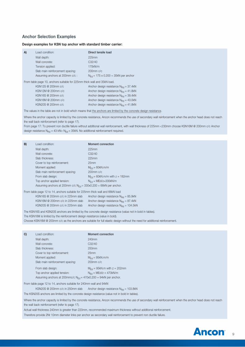
Anchor Selection Examples
Design examples for KSN top anchor with standard timber carrier:
A) Load condition: Direct tensile load
Wall depth: 225mm Wall concrete: C32/40 Tension applied: 175kN/m Slab main reinforcement spacing: 200mm c/c Assuming anchors at 200mm c/c : NEd = 175 x 0.200 = 35kN per anchor
From table page 10, anchors suitable for 225mm thick wall and 35kN load. KSN12S @ 200mm c/c Anchor design resistance NRd = 37.4kN KSN12M @ 200mm c/c Anchor design resistance NRd = 41.8kN KSN16S @ 200mm c/c Anchor design resistance NRd = 39.4kN KSN16M @ 200mm c/c Anchor design resistance NRd = 43.0kN KSN20S @ 200mm c/c Anchor design resistance NRd = 41.8kN
The values in the table are not in bold which means that the anchors are limited by the concrete design resistance.
Where the anchor capacity is limited by the concrete resistance, Ancon recommends the use of secondary wall reinforcement when the anchor head does not reach the wall back reinforcement (refer to page 17).From page 17: To prevent non ductile failure without additional wall reinforcement, with wall thickness of 225mm <230mm choose KSN16M @ 200mm c/c Anchor design resistance NRd = 43 kN> NEd = 35kN. No additional reinforcement required.
B) Load condition: Moment connection
Wall depth: 225mm Wall concrete: C32/40 Slab thickness: 225mm Cover to top reinforcement: 25mm Moment applied: MEd = 60kN.m/m Slab main reinforcement spacing: 200mm c/c From slab design: MEd = 60kN.m/m with z = 182mm Top anchor applied tension: NEd = MEd/z=330kN/m Assuming anchors at 200mm c/c NEd = 330x0.200 = 66kN per anchor.
From table page 12 to 14, anchors suitable for 225mm thick wall and 66kN load KSN16S @ 200mm c/c in 225mm slab Anchor design resistance NRd = 85.9kN KSN16M @ 200mm c/c in 225mm slab Anchor design resistance NRd = 87.4kN KSN20S @ 200mm c/c in 225mm slab Anchor design resistance NRd = 104.5kN
The KSN16S and KSN20S anchors are limited by the concrete design resistance (value not in bold in tables).The KSN16M is limited by the reinforcement design resistance (value in bold).Choose KSN16M @ 200mm c/c as the anchors are suitable for full elastic design without the need for additional reinforcement.
C) Load condition: Moment connection
Wall depth: 240mm Wall concrete: C32/40 Slab thickness: 250mm Cover to top reinforcement: 25mm Moment applied: MEd = 95kN.m/m Slab main reinforcement spacing: 200mm c/c
From slab design: MEd = 95kN.m with z = 202mm Top anchor applied tension: NEd = MEd/z = 470kN/m Assuming anchors at 200mmc/c NEd = 470x0.200 = 94kN per anchor.
From table page 12 to 14, anchors suitable for 240mm wall and 94kN
KSN20S @ 200mm c/c in 250mm slab Anchor design resistance NRd = 103.8kN
The KSN20S anchors are limited by the concrete design resistance (value not in bold in tables).
Where the anchor capacity is limited by the concrete resistance, Ancon recommends the use of secondary wall reinforcement when the anchor head does not reach the wall back reinforcement (refer to page 17).
Actual wall thickness 240mm is greater than 220mm, recommended maximum thickness without additional reinforcement.
Therefore provide 2Nr 10mm diameter links per anchor as secondary wall reinforcement to prevent non ductile failure.
10 Tel: +44 (0) 114 275 5224 www.ancon.co.uk
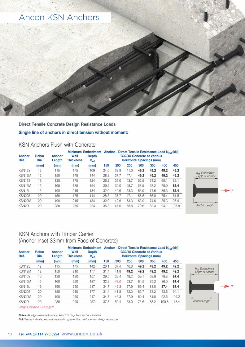
Direct Tensile Concrete Design Resistance Loads
Minimum Embedment Anchor - Direct Tensile Resistance Load NRd (kN) Anchor Rebar Anchor Wall Depth C32/40 Concrete at Various Ref. Dia. Length Thickness heff Horizontal Spacings (mm)
(mm) (mm) (mm) (mm) 150 200 250 300 350 400 450KSN12S 12 115 175 109 24.6 32.8 41.0 49.2 49.2 49.2 49.2KSN12M 12 150 175 144 28.3 37.7 47.1 49.2 49.2 49.2 49.2KSN16S 16 130 175 124 26.2 35.0 43.7 52.5 61.2 65.1 65.1KSN16M 16 160 185 154 29.2 39.0 48.7 58.5 68.2 78.0 87.4KSN16L 16 190 215 184 32.0 42.6 53.3 63.9 74.6 85.3 87.4KSN20S 20 150 175 144 28.3 37.7 47.1 56.6 66.0 75.4 81.5KSN20M 20 190 215 184 32.0 42.6 53.3 63.9 74.6 85.3 95.9KSN20L 20 230 255 224 35.3 47.0 58.8 70.6 82.3 94.1 105.8
Minimum Embedment Anchor - Direct Tensile Resistance Load NRd (kN) Anchor Rebar Anchor Wall Depth C32/40 Concrete at Various Ref. Dia. Length Thickness heff Horizontal Spacings (mm)
(mm) (mm) (mm) (mm) 150 200 250 300 350 400 450KSN12S 12 115 175 142 28.1 37.4 46.8 49.2 49.2 49.2 49.2KSN12M 12 150 210 177 31.4 41.8 49.2 49.2 49.2 49.2 49.2KSN16S 16 130 190 157 29.5 39.4 49.2 59.1 68.9 78.8 87.4KSN16M 16 160 220 187 32.2 43.0 53.7 64.5 75.2 86.0 87.4KSN16L 16 190 250 217 34.7 46.3 57.9 69.4 81.0 87.4 87.4KSN20S 20 150 210 177 31.4 41.8 52.3 62.7 73.2 83.6 94.1KSN20M 20 190 250 217 34.7 46.3 57.9 69.4 81.0 92.6 104.2KSN20L 20 230 290 257 37.8 50.4 63.0 75.6 88.2 100.8 113.4Design Example A. See page 9 Notes: All edges assumed to be at least 1.5 x heff from anchor centreline. Bold figures indicate performance equal or greater than reinforcement design resistance.
KSN Anchors Flush with Concrete
KSN Anchors with Timber Carrier (Anchor Inset 33mm from Face of Concrete)
Ancon KSN Anchors
Single line of anchors in direct tension without moment:
heff Embedment Depth of Anchor
Anchor Length
T
heff Embedment Depth of Anchor
Anchor Length
T
11
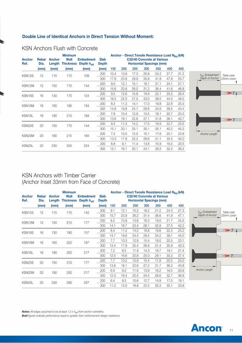
Double Line of Identical Anchors in Direct Tension Without Moment:
Notes: All edges assumed to be at least 1.5 x heff from anchor centreline. Bold figures indicate performance equal or greater than reinforcement design resistance.
Minimum Anchor - Direct Tensile Resistance Load NRd (kN) Anchor Rebar Anchor Wall Embedment Slab C32/40 Concrete at Various Ref. Dia. Length Thickness Depth heff Depth Horizontal Spacings (mm)
(mm) (mm) (mm) (mm) (mm) 150 200 250 300 350 400 450
KSN12S 12 115 175 109 200 10.4 13.9 17.3 20.8 24.2 27.7 31.2 300 17.9 23.9 29.9 35.8 41.8 47.8 53.7
KSN12M 12 150 175 144 200 9.0 12.1 15.1 18.1 21.1 24.1 27.1 300 15.6 20.8 26.0 31.2 36.4 41.6 46.8
KSN16S 16 130 175 124 200 9.5 12.6 15.8 18.9 22.1 25.2 28.4 300 16.5 22.0 27.5 33.0 38.5 44.0 49.5
KSN16M 16 160 185 154 200 8.5 11.3 14.1 17.0 19.8 22.6 25.5 300 14.8 19.8 24.7 29.6 34.6 39.5 44.4
KSN16L 16 190 215 184 200 7.8 10.4 12.9 15.5 18.1 20.7 23.3 300 13.6 18.1 22.6 27.1 31.6 36.1 40.7
KSN20S 20 150 175 144 200 8.5 11.3 14.2 17.0 19.9 22.7 25.5 300 15.1 20.1 25.1 30.1 35.1 40.2 45.2
KSN20M 20 190 215 184 200 7.5 10.0 12.5 15.1 17.6 20.1 22.6 300 13.3 17.8 22.2 26.6 31.1 35.5 40.0
KSN20L 20 230 255 224 200 6.8 9.1 11.4 13.6 15.9 18.2 20.5 300 12.1 16.1 20.1 24.1 28.2 32.2 36.2
KSN Anchors Flush with Concrete
Minimum Anchor - Direct Tensile Resistance Load NRd (kN) Anchor Rebar Anchor Wall Embedment Slab C32/40 Concrete at Various Ref. Dia. Length Thickness Depth heff Depth Horizontal Spacings (mm)
(mm) (mm) (mm) (mm) (mm) 150 200 250 300 350 400 450
KSN12S 12 115 175 142 200 9.1 12.1 15.2 18.2 21.2 24.3 27.3 300 15.7 20.9 26.2 31.4 36.6 41.9 47.1
KSN12M 12 150 210 177 200 8.2 10.9 13.6 16.3 19.0 21.7 24.5 300 14.1 18.7 23.4 28.1 32.8 37.5 42.2
KSN16S 16 130 190 157 200 8.4 11.2 14.0 16.8 19.6 22.4 25.2 300 14.7 19.6 24.4 29.4 34.2 39.1 44.0
KSN16M 16 160 220 187 200 7.7 10.3 12.8 15.4 18.0 20.5 23.1 300 13.4 17.9 22.4 26.9 31.4 35.9 40.3
KSN16L 16 190 250 217 200 7.2 9.5 11.9 14.3 16.7 19.1 21.4 300 12.5 16.6 20.8 25.0 29.1 33.2 37.4
KSN20S 20 150 210 177 200 7.7 10.2 12.8 15.4 17.9 20.5 23.0 300 13.6 18.1 22.6 27.2 31.7 36.2 40.8
KSN20M 20 190 250 217 200 6.9 9.2 11.6 13.9 16.2 18.5 20.8 300 12.3 16.4 20.5 24.5 28.6 32.7 36.8
KSN20L 20 230 290 257 200 6.4 8.5 10.6 12.7 14.9 17.0 19.1 300 11.3 15.0 18.8 22.5 26.3 30.1 33.8
KSN Anchors with Timber Carrier (Anchor Inset 33mm from Face of Concrete)
T
T
heff Embedment Depth of Anchor
Table uses 25mm cover
Anchor Length
T
T
heff Embedment Depth of Anchor
Anchor Length
Table uses 25mm cover
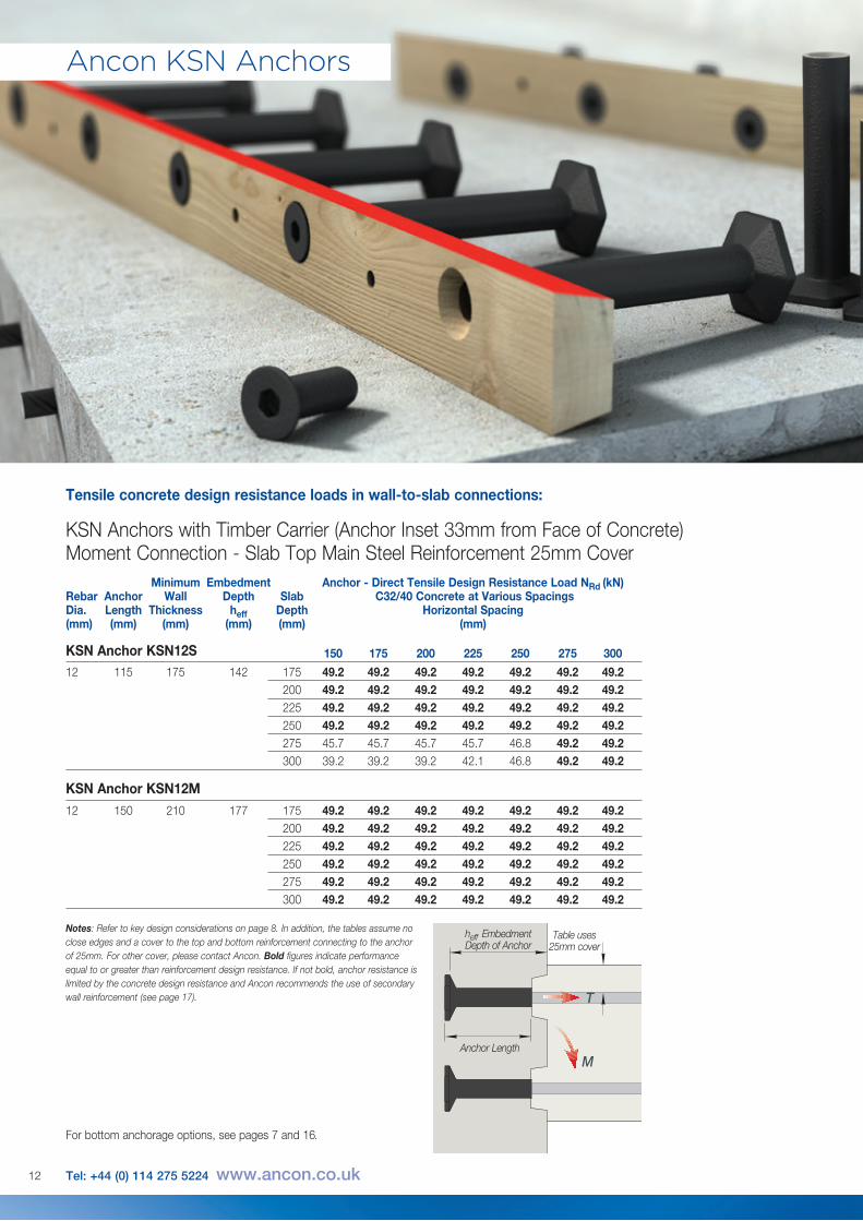
Minimum Embedment Anchor - Direct Tensile Design Resistance Load NRd (kN) Rebar Anchor Wall Depth Slab C32/40 Concrete at Various Spacings Dia. Length Thickness heff Depth Horizontal Spacing (mm) (mm) (mm) (mm) (mm) (mm) 150 175 200 225 250 275 300
12 115 175 142 175 49.2 49.2 49.2 49.2 49.2 49.2 49.2 200 49.2 49.2 49.2 49.2 49.2 49.2 49.2 225 49.2 49.2 49.2 49.2 49.2 49.2 49.2 250 49.2 49.2 49.2 49.2 49.2 49.2 49.2 275 45.7 45.7 45.7 45.7 46.8 49.2 49.2 300 39.2 39.2 39.2 42.1 46.8 49.2 49.2 KSN Anchor KSN12M12 150 210 177 175 49.2 49.2 49.2 49.2 49.2 49.2 49.2 200 49.2 49.2 49.2 49.2 49.2 49.2 49.2 225 49.2 49.2 49.2 49.2 49.2 49.2 49.2 250 49.2 49.2 49.2 49.2 49.2 49.2 49.2 275 49.2 49.2 49.2 49.2 49.2 49.2 49.2 300 49.2 49.2 49.2 49.2 49.2 49.2 49.2
KSN Anchor KSN12S
T
M
heff Embedment Depth of Anchor
Anchor Length
Table uses 25mm cover
Ancon KSN Anchors
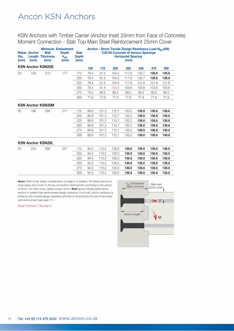
KSN Anchors with Timber Carrier (Anchor Inset 33mm from Face of Concrete)Moment Connection - Slab Top Main Steel Reinforcement 25mm Cover
12 Tel: +44 (0) 114 275 5224 www.ancon.co.uk
Tensile concrete design resistance loads in wall-to-slab connections:
For bottom anchorage options, see pages 7 and 16.
Notes: Refer to key design considerations on page 8. In addition, the tables assume no close edges and a cover to the top and bottom reinforcement connecting to the anchor of 25mm. For other cover, please contact Ancon. Bold figures indicate performance equal to or greater than reinforcement design resistance. If not bold, anchor resistance is limited by the concrete design resistance and Ancon recommends the use of secondary wall reinforcement (see page 17).
T
M
heff Embedment Depth of Anchor
Anchor Length
Table uses 25mm cover
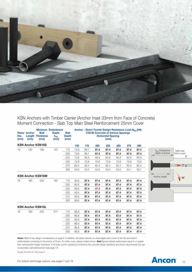
Minimum Embedment Anchor - Direct Tensile Design Resistance Load NRd (kN) Rebar Anchor Wall Depth Slab C32/40 Concrete at Various Spacings Dia. Length Thickness heff Depth Horizontal Spacing (mm) (mm) (mm) (mm) (mm) (mm)
150 175 200 225 250 275 30016 130 190 157 175 73.8 86.1 87.4 87.4 87.4 87.4 87.4 200 73.8 86.1 87.4 87.4 87.4 87.4 87.4 225 73.8 85.9 85.9 85.9 85.9 85.9 85.9 250 72.8 72.8 72.8 72.8 72.8 72.8 72.8 275 62.4 62.4 62.4 62.4 62.4 62.4 62.4 300 54.0 54.0 54.0 54.0 54.0 54.1 59.1 KSN Anchor KSN16M16 160 220 187 175 80.6 87.4 87.4 87.4 87.4 87.4 87.4 200 80.6 87.4 87.4 87.4 87.4 87.4 87.4 225 80.6 87.4 87.4 87.4 87.4 87.4 87.4 250 80.6 87.4 87.4 87.4 87.4 87.4 87.4 275 80.6 87.4 87.4 87.4 87.4 87.4 87.4 300 80.6 87.4 87.4 87.4 87.4 87.4 87.4 KSN Anchor KSN16L16 190 250 217 175 86.8 87.4 87.4 87.4 87.4 87.4 87.4 200 86.8 87.4 87.4 87.4 87.4 87.4 87.4 225 86.8 87.4 87.4 87.4 87.4 87.4 87.4 250 86.8 87.4 87.4 87.4 87.4 87.4 87.4 275 86.8 87.4 87.4 87.4 87.4 87.4 87.4 300 86.8 87.4 87.4 87.4 87.4 87.4 87.4 Notes: Refer to key design considerations on page 8. In addition, the tables assume no close edges and a cover to the top and bottom reinforcement connecting to the anchor of 25mm. For other cover, please contact Ancon. Bold figures indicate performance equal to or greater than reinforcement design resistance. If not bold, anchor resistance is limited by the concrete design resistance and Ancon recommends the use of secondary wall reinforcement (see page 17).
Design Example B. See page 9
KSN Anchors with Timber Carrier (Anchor Inset 33mm from Face of Concrete)Moment Connection - Slab Top Main Steel Reinforcement 25mm Cover
13
KSN Anchor KSN16S
For bottom anchorage options, see pages 7 and 16.
T
M
heff Embedment Depth of Anchor
Anchor Length
Table uses 25mm cover
Ancon KSN Anchors
14 Tel: +44 (0) 114 275 5224 www.ancon.co.uk
Minimum Embedment Anchor - Direct Tensile Design Resistance Load NRd (kN) Rebar Anchor Wall Depth Slab C32/40 Concrete at Various Spacings Dia. Length Thickness heff Depth Horizontal Spacing (mm) (mm) (mm) (mm) (mm) (mm) 150 175 200 225 250 275 30020 150 210 177 175 78.4 91.5 104.5 117.6 130.7 136.6 136.6 200 78.4 91.5 104.5 117.6 130.7 136.6 136.6 225 78.4 91.5 104.5 117.6 121.8 121.8 121.8 250 78.4 91.5 103.8 103.8 103.8 103.8 103.8 275 78.4 89.5 89.5 89.5 89.5 89.5 89.5 300 77.9 77.9 77.9 77.9 77.9 77.9 77.9 KSN Anchor KSN20M20 190 250 217 175 86.8 101.3 115.7 130.2 136.6 136.6 136.6 200 86.8 101.3 115.7 130.2 136.6 136.6 136.6 225 86.8 101.3 115.7 130.2 136.6 136.6 136.6 250 86.8 101.3 115.7 130.2 136.6 136.6 136.6 275 86.8 101.3 115.7 130.2 136.6 136.6 136.6 300 86.8 101.3 115.7 130.2 136.6 136.6 136.6 KSN Anchor KSN20L20 230 290 257 175 94.5 110.2 126.0 136.6 136.6 136.6 136.6 200 94.5 110.2 126.0 136.6 136.6 136.6 136.6 225 94.5 110.2 126.0 136.6 136.6 136.6 136.6 250 94.5 110.2 126.0 136.6 136.6 136.6 136.6 275 94.5 110.2 126.0 136.6 136.6 136.6 136.6 300 94.5 110.2 126.0 136.6 136.6 136.6 136.6
KSN Anchor KSN20S
KSN Anchors with Timber Carrier (Anchor Inset 33mm from Face of Concrete)Moment Connection - Slab Top Main Steel Reinforcement 25mm Cover
Notes: Refer to key design considerations on page 8. In addition, the tables assume no close edges and a cover to the top and bottom reinforcement connecting to the anchor of 25mm. For other cover, please contact Ancon. Bold figures indicate performance equal to or greater than reinforcement design resistance. If not bold, anchor resistance is limited by the concrete design resistance and Ancon recommends the use of secondary wall reinforcement (see page 17).
Design Example C. See page 9
15
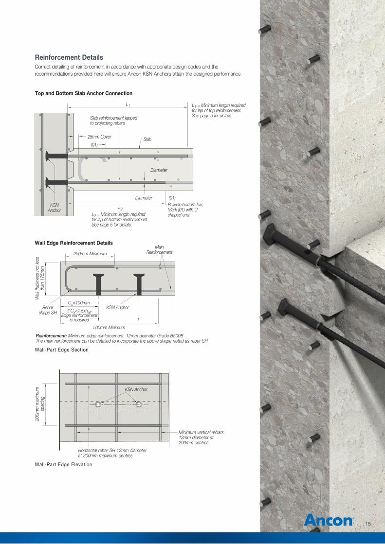
Reinforcement DetailsCorrect detailing of reinforcement in accordance with appropriate design codes and the recommendations provided here will ensure Ancon KSN Anchors attain the designed performance.
Main Reinforcement
Wall-Part Edge Section
Wall-Part Edge Elevation
250mm Minimum
Wal
l thi
ckne
ss n
ot le
ss
than
175
mm
200m
m m
axim
um
spac
ing
500mm Minimum
Reinforcement: Minimum edge reinforcement, 12mm diameter Grade B500BThe main reinforcement can be detailed to incorporate the above shape noted as rebar SH
KSN Anchor
KSN Anchor
Horizontal rebar SH 12mm diameter at 200mm maximum centres
Minimum vertical rebars 12mm diameter at 200mm centres
Rebar shape SH
Cx≥100mm
If Cx<1.5xheffEdge reinforcement
is required
Top and Bottom Slab Anchor Connection
KSN Anchor
25mm Cover
Diameter
(01)
(01)
L2
L1
Slab
DiameterProvide bottom bar, Mark (01) with U shaped end
Slab reinforcement lapped to projecting rebars
L1 = Minimum length required for lap of top reinforcement. See page 5 for details.
L2 = Minimum length required for lap of bottom reinforcement. See page 5 for details.
Wall Edge Reinforcement Details
16 Tel: +44 (0) 114 275 5224 www.ancon.co.uk
Ancon KSN Anchors
KSN Anchor
Coupler Box
25mm Cover
(1)
(1)
20mm minimum cover to top and bottom rebars
Projecting rebars with threaded ends to suit Ancon KSN Anchor and Coupler Box
Slab reinforcement lapped to projecting rebars.
Slab
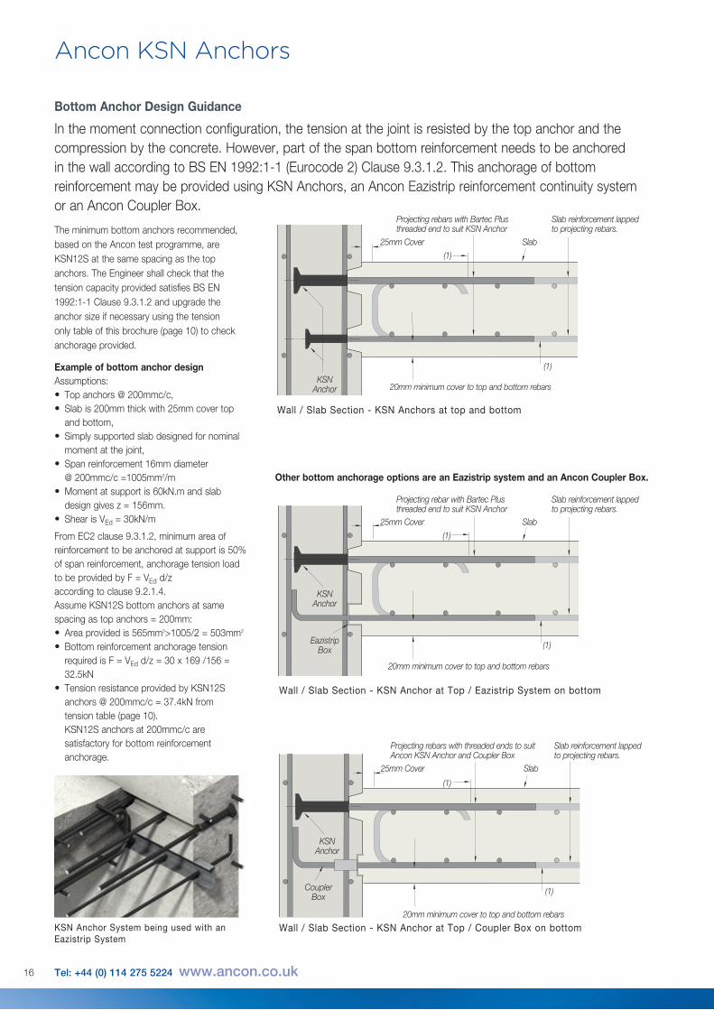
Bottom Anchor Design Guidance
In the moment connection configuration, the tension at the joint is resisted by the top anchor and the compression by the concrete. However, part of the span bottom reinforcement needs to be anchored in the wall according to BS EN 1992:1-1 (Eurocode 2) Clause 9.3.1.2. This anchorage of bottom reinforcement may be provided using KSN Anchors, an Ancon Eazistrip reinforcement continuity system or an Ancon Coupler Box.
Example of bottom anchor designAssumptions:• Top anchors @ 200mmc/c,• Slab is 200mm thick with 25mm cover top
and bottom,• Simply supported slab designed for nominal
moment at the joint,• Span reinforcement 16mm diameter
@ 200mmc/c =1005mm2/m• Moment at support is 60kN.m and slab
design gives z = 156mm.• Shear is VEd = 30kN/m
From EC2 clause 9.3.1.2, minimum area of reinforcement to be anchored at support is 50% of span reinforcement, anchorage tension load to be provided by F = VEd d/z according to clause 9.2.1.4. Assume KSN12S bottom anchors at same spacing as top anchors = 200mm:• Area provided is 565mm2>1005/2 = 503mm2
• Bottom reinforcement anchorage tension required is F = VEd d/z = 30 x 169 /156 = 32.5kN
• Tension resistance provided by KSN12S anchors @ 200mmc/c = 37.4kN from tension table (page 10).
KSN12S anchors at 200mmc/c are satisfactory for bottom reinforcement anchorage.
Other bottom anchorage options are an Eazistrip system and an Ancon Coupler Box.
The minimum bottom anchors recommended, based on the Ancon test programme, are KSN12S at the same spacing as the top anchors. The Engineer shall check that the tension capacity provided satisfies BS EN 1992:1-1 Clause 9.3.1.2 and upgrade the anchor size if necessary using the tension only table of this brochure (page 10) to check anchorage provided.
Wall / Slab Section - KSN Anchors at top and bottom
Wall / Slab Section - KSN Anchor at Top / Eazistrip System on bottom
Wall / Slab Section - KSN Anchor at Top / Coupler Box on bottom
KSN Anchor
KSN Anchor
Eazistrip Box
25mm Cover
25mm Cover
(1)
(1)
(1)
(1)
20mm minimum cover to top and bottom rebars
20mm minimum cover to top and bottom rebars
Projecting rebars with Bartec Plus threaded end to suit KSN Anchor
Projecting rebar with Bartec Plus threaded end to suit KSN Anchor
Slab reinforcement lapped to projecting rebars.
Slab reinforcement lapped to projecting rebars.
Slab
Slab
KSN Anchor System being used with an Eazistrip System
17
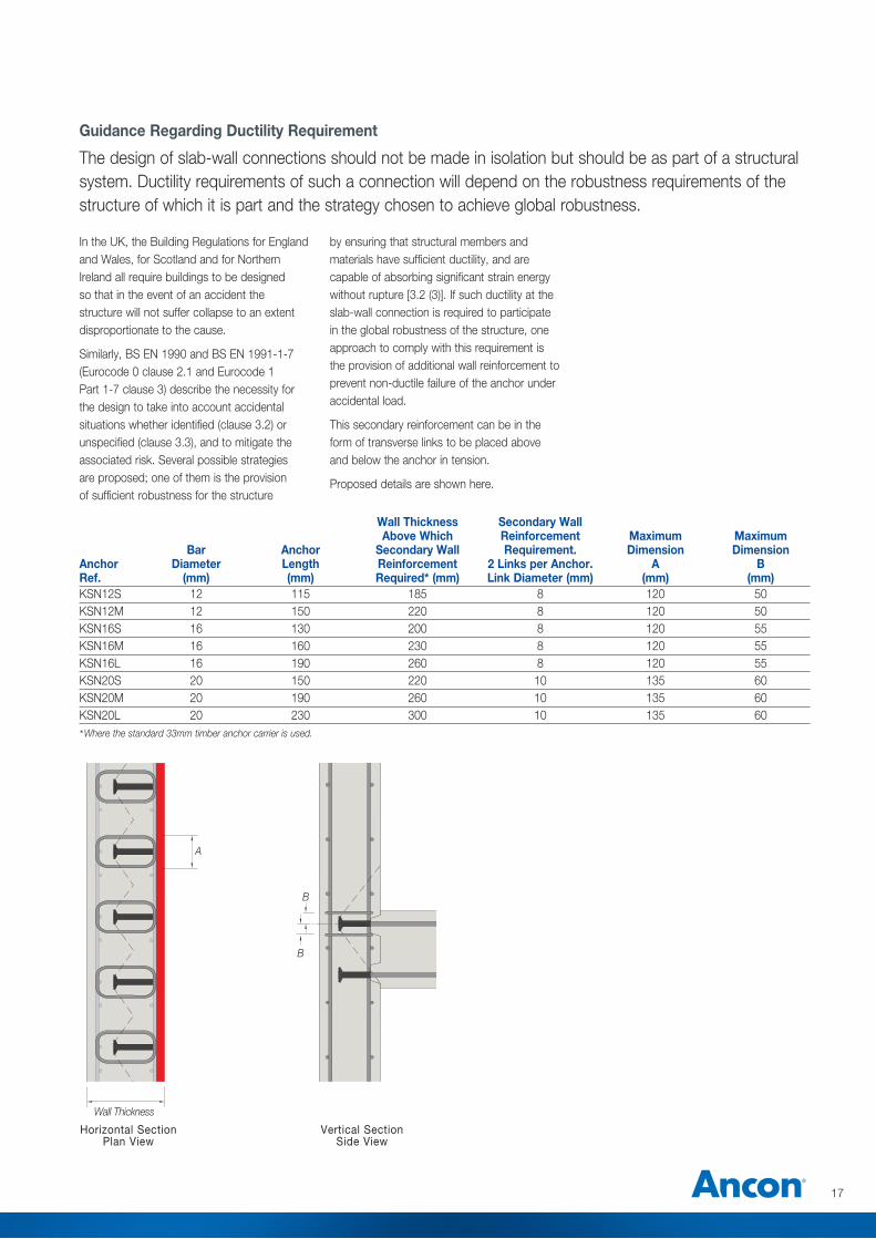
Guidance Regarding Ductility Requirement
The design of slab-wall connections should not be made in isolation but should be as part of a structural system. Ductility requirements of such a connection will depend on the robustness requirements of the structure of which it is part and the strategy chosen to achieve global robustness.
In the UK, the Building Regulations for England and Wales, for Scotland and for Northern Ireland all require buildings to be designed so that in the event of an accident the structure will not suffer collapse to an extent disproportionate to the cause.
Similarly, BS EN 1990 and BS EN 1991-1-7 (Eurocode 0 clause 2.1 and Eurocode 1 Part 1-7 clause 3) describe the necessity for the design to take into account accidental situations whether identified (clause 3.2) or unspecified (clause 3.3), and to mitigate the associated risk. Several possible strategies are proposed; one of them is the provision of sufficient robustness for the structure
by ensuring that structural members and materials have sufficient ductility, and are capable of absorbing significant strain energy without rupture [3.2 (3)]. If such ductility at the slab-wall connection is required to participate in the global robustness of the structure, one approach to comply with this requirement is the provision of additional wall reinforcement to prevent non-ductile failure of the anchor under accidental load.
This secondary reinforcement can be in the form of transverse links to be placed above and below the anchor in tension.
Proposed details are shown here.
Wall Thickness Secondary Wall Above Which Reinforcement Maximum Maximum Bar Anchor Secondary Wall Requirement. Dimension Dimension Anchor Diameter Length Reinforcement 2 Links per Anchor. A B Ref. (mm) (mm) Required* (mm) Link Diameter (mm) (mm) (mm)KSN12S 12 115 185 8 120 50KSN12M 12 150 220 8 120 50KSN16S 16 130 200 8 120 55KSN16M 16 160 230 8 120 55KSN16L 16 190 260 8 120 55KSN20S 20 150 220 10 135 60KSN20M 20 190 260 10 135 60KSN20L 20 230 300 10 135 60
*Where the standard 33mm timber anchor carrier is used.
A
B
B
Wall Thickness
Vertical SectionSide View
Horizontal SectionPlan View
18 Tel: +44 (0) 114 275 5224 www.ancon.co.uk
Ancon KSN Anchors
2Nr U bar 12mm diameter minimum, 60mm maximum above and below anchors
2Nr U bar 12mm diameter minimum, 100mm maximum above and below anchors
2Nr U bar 12mm diameter minimum, 100mm maximum above and below anchors
2Nr U bar 12mm diameter minimum, 60mm maximum above and below anchors
Tension lap
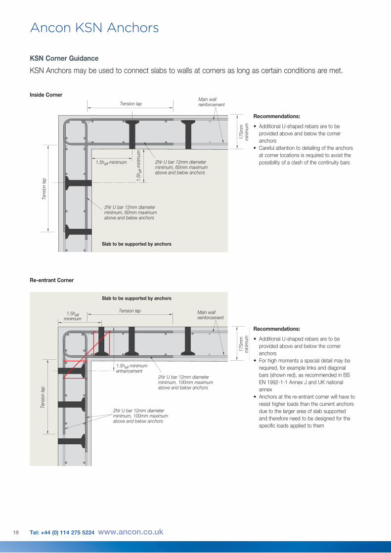
KSN Corner Guidance
KSN Anchors may be used to connect slabs to walls at corners as long as certain conditions are met.
Recommendations:
• Additional U-shaped rebars are to be provided above and below the corner anchors
• Carefulattentiontodetailingoftheanchorsat corner locations is required to avoid the possibility of a clash of the continuity bars
Recommendations:
• Additional U-shaped rebars are to be provided above and below the corner anchors
• For high moments a special detail may be required, for example links and diagonal bars (shown red), as recommended in BS EN 1992-1-1 Annex J and UK national annex
• Anchors at the re-entrant corner will have to resist higher loads than the current anchors due to the larger area of slab supported and therefore need to be designed for the specific loads applied to them
Inside Corner
Re-entrant Corner
Main wall reinforcement
Tens
ion
lap
Tens
ion
lap
Tension lap1.5heff minimum
1.5heff minimum
1.5h
eff m
inim
um
1.5heff minimum enhancement
Main wall reinforcement
175m
m
min
imum
175m
m
min
imum
Slab to be supported by anchors
Slab to be supported by anchors
19
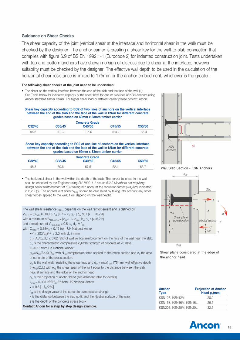
Guidance on Shear Checks
The shear capacity of the joint (vertical shear at the interface and horizontal shear in the wall) must be checked by the designer. The anchor carrier is creating a shear key for the wall-to-slab connection that complies with figure 6.9 of BS EN 1992:1-1 (Eurocode 2) for indented construction joint. Tests undertaken with top and bottom anchors have shown no sign of distress due to shear at the interface, however suitability must be checked by the designer. The effective wall depth to be used in the calculation of the horizontal shear resistance is limited to 175mm or the anchor embedment, whichever is the greater.
The following shear checks at the joint need to be undertaken:
• The shear on the vertical interface between the end of the slab and the face of the wall (1): See Table below for indicative capacity of the shear keys for one or two lines of KSN Anchors using
Ancon standard timber carrier. For higher shear load or different carrier please contact Ancon.
Shear key capacity according to EC2 of two lines of anchors on the vertical interface between the end of the slab and the face of the wall in kN/m for different concrete
grades based on 69mm x 33mm timber carrier
Concrete Grade C32/40 C35/45 C40/50 C45/55 C50/60
96.6 101.2 115.0 124.2 133.4
Shear key capacity according to EC2 of one line of anchors on the vertical interface between the end of the slab and the face of the wall in kN/m for different concrete
grades based on 69mm x 33mm timber carrier
Concrete Grade C32/40 C35/45 C40/50 C45/55 C50/60
48.3 50.6 57.5 52.1 66.7
Anchor Projection of Anchor Type Head ph(mm) KSN12S, KSN12M 20.0KSN16S, KSN16M, KSN16L 26.5 KSN20S, KSN20M, KSN20L 32.5
• Thehorizontalshearinthewallwithinthedepthoftheslab.Thehorizontalshearinthewallshall be checked by the Engineer using EN 1992-1-1 clause 6.2.2 Members not requiring design shear reinforcement of EC2 taking into account the reduction factorβ=av/(2d) indicated in 6.2.2 (6). The applied joint shear VEd,jt should be calculated by taking into account any other shear forces applied to the wall; it will depend on the wall height.
The wall shear resistance VRd,c depends on the wall reinforcement and is defined by:VRd,c = [CRd,c k (100 ρ1 fck )(1/3) + k1 σcp ] bw dw / β (6.2.a)with a minimum of VRd,c,min = [vmin+ k1 σcp ] bw dw / β (6.2.b)and a maximum of VRd,c,max = 0.5 bw dw ν fcd
with CRd,c = 0.18/γc = 0.12 from UK National Annex k=1+(200/dw)0.5 ≤ 2.0 with dw in mm ρ1= Asl/(bwdw) ≤ 0.02 ratio of wall vertical reinforcement on the face of the wall near the slab. fck is the characteristic compressive cylinder strength of concrete at 28 days k1=0.15 from UK National Annex σcp=NEd/Ac<0.2fcd with NEd compression force applied to the cross section and Ac the area of concrete of the cross section. bw is the wall width resisting the shear load and dw = max(heff,175mm), wall effective depth β=avjt/(2dw) with avjt the shear span of the joint equal to the distance between the slab neutral surface and the edge of the anchor head ph is the projection of anchor head (see adjacent table for details) vmin = 0.035 k(3/2) fck 0.5 from UK National Annex ν = 0.6 [1-fck/250] fcd is the design value of the concrete compressive strength x is the distance between the slab soffit and the Neutral surface of the slab s is the depth of the concrete stress blockContact Ancon for a step by step design example.
x
M
C
d
s/2
T
z
Neutral surface
heff
ph
avjt
Shear plane consideration
Wall
Slab
(1)KSN Anchors
Wall/Slab Section - KSN Anchors
Shear plane considered at the edge of the anchor head
Ancon KSN Anchors
20 Tel: +44 (0) 114 275 5224 www.ancon.co.uk
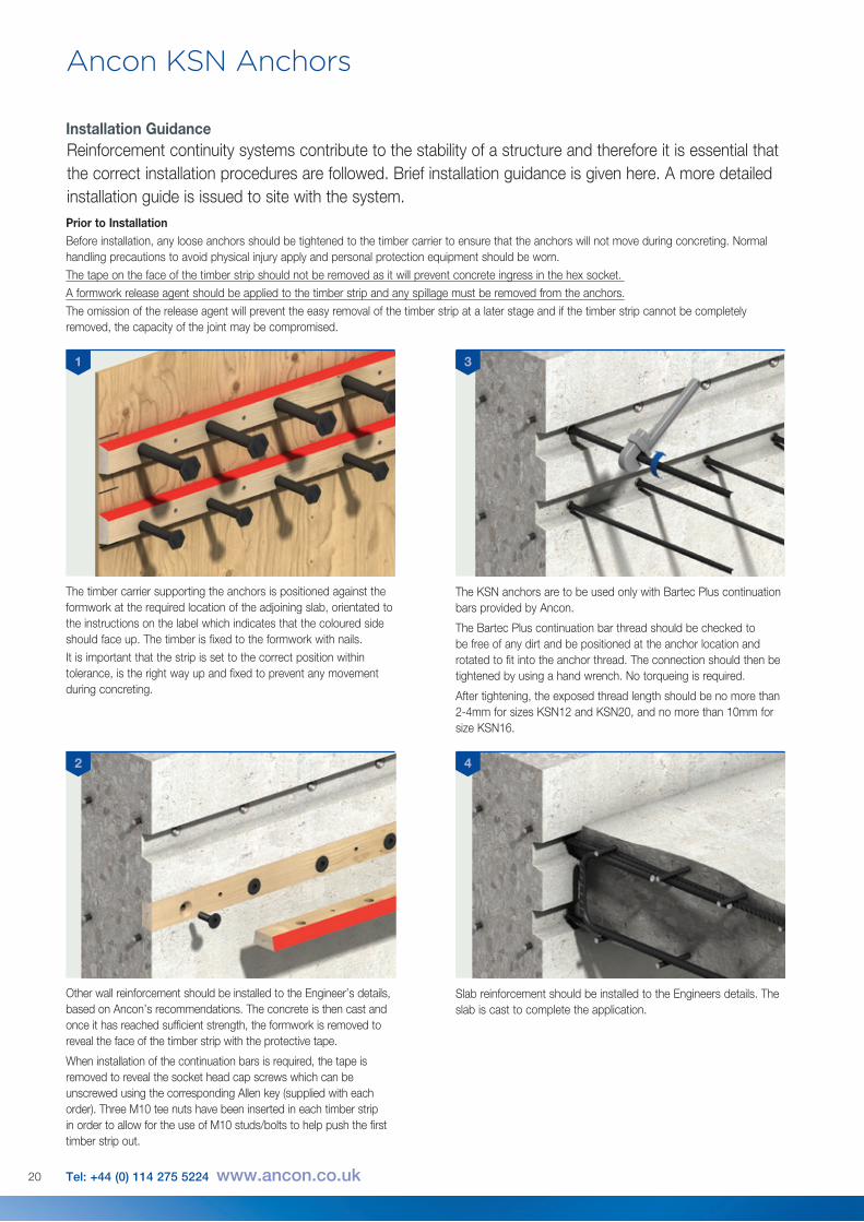
Installation GuidanceReinforcement continuity systems contribute to the stability of a structure and therefore it is essential that the correct installation procedures are followed. Brief installation guidance is given here. A more detailed installation guide is issued to site with the system.
1
Prior to InstallationBefore installation, any loose anchors should be tightened to the timber carrier to ensure that the anchors will not move during concreting. Normal handling precautions to avoid physical injury apply and personal protection equipment should be worn.The tape on the face of the timber strip should not be removed as it will prevent concrete ingress in the hex socket. A formwork release agent should be applied to the timber strip and any spillage must be removed from the anchors.The omission of the release agent will prevent the easy removal of the timber strip at a later stage and if the timber strip cannot be completely removed, the capacity of the joint may be compromised.
The timber carrier supporting the anchors is positioned against the formwork at the required location of the adjoining slab, orientated to the instructions on the label which indicates that the coloured side should face up. The timber is fixed to the formwork with nails.It is important that the strip is set to the correct position within tolerance, is the right way up and fixed to prevent any movement during concreting.
The KSN anchors are to be used only with Bartec Plus continuation bars provided by Ancon.
The Bartec Plus continuation bar thread should be checked to be free of any dirt and be positioned at the anchor location and rotated to fit into the anchor thread. The connection should then be tightened by using a hand wrench. No torqueing is required.
After tightening, the exposed thread length should be no more than 2-4mm for sizes KSN12 and KSN20, and no more than 10mm for size KSN16.
Other wall reinforcement should be installed to the Engineer’s details, based on Ancon’s recommendations. The concrete is then cast and once it has reached sufficient strength, the formwork is removed to reveal the face of the timber strip with the protective tape.
When installation of the continuation bars is required, the tape is removed to reveal the socket head cap screws which can be unscrewed using the corresponding Allen key (supplied with each order). Three M10 tee nuts have been inserted in each timber strip in order to allow for the use of M10 studs/bolts to help push the first timber strip out.
Slab reinforcement should be installed to the Engineers details. The slab is cast to complete the application.
3
2 4
21
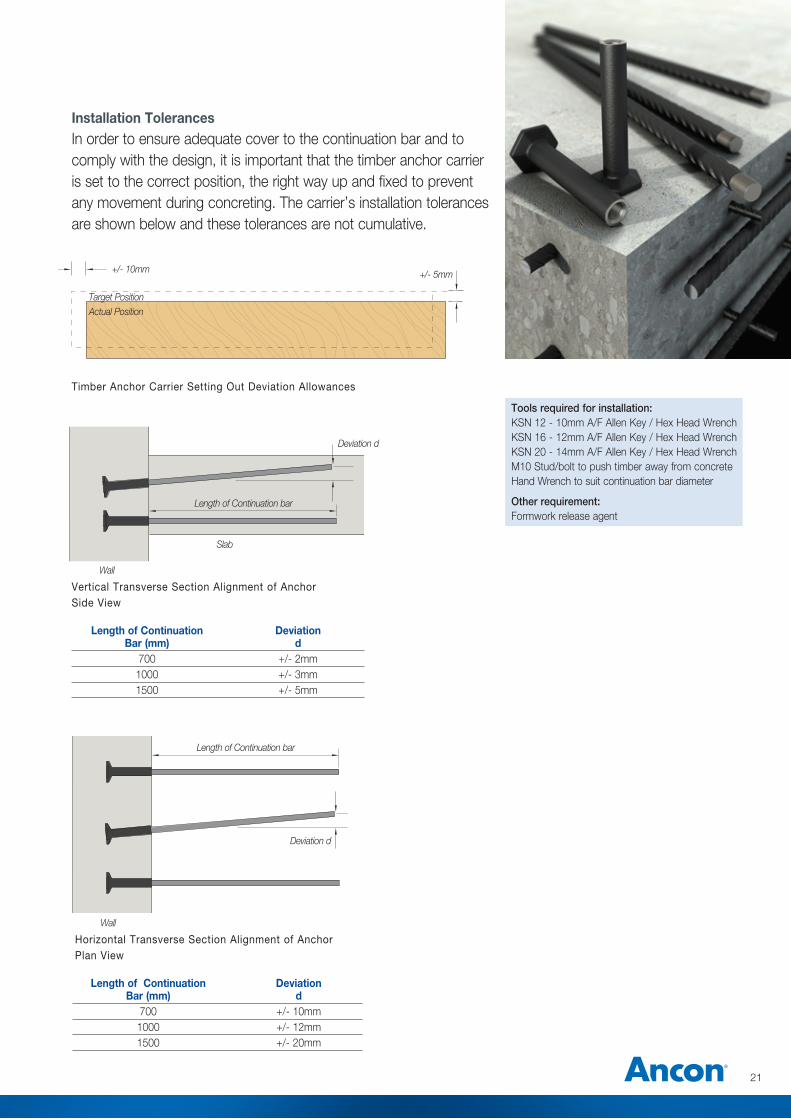
Installation TolerancesIn order to ensure adequate cover to the continuation bar and to comply with the design, it is important that the timber anchor carrier is set to the correct position, the right way up and fixed to prevent any movement during concreting. The carrier’s installation tolerances are shown below and these tolerances are not cumulative.
Tools required for installation: KSN 12 - 10mm A/F Allen Key / Hex Head WrenchKSN 16 - 12mm A/F Allen Key / Hex Head Wrench KSN 20 - 14mm A/F Allen Key / Hex Head WrenchM10 Stud/bolt to push timber away from concreteHand Wrench to suit continuation bar diameter
Other requirement: Formwork release agent
Length of Continuation Deviation Bar (mm) d 700 +/- 2mm 1000 +/- 3mm 1500 +/- 5mm
Length of Continuation Deviation Bar (mm) d 700 +/- 10mm 1000 +/- 12mm 1500 +/- 20mm
+/- 10mm
Target Position
Length of Continuation bar
Slab
Wall
Wall
Deviation d
Length of Continuation bar
Deviation d
Actual Position
+/- 5mm
Timber Anchor Carrier Setting Out Deviation Allowances
Vertical Transverse Section Alignment of Anchor Side View
Horizontal Transverse Section Alignment of Anchor Plan View
22 Tel: +44 (0) 114 275 5224 www.ancon.co.uk
Ancon KSN Anchors
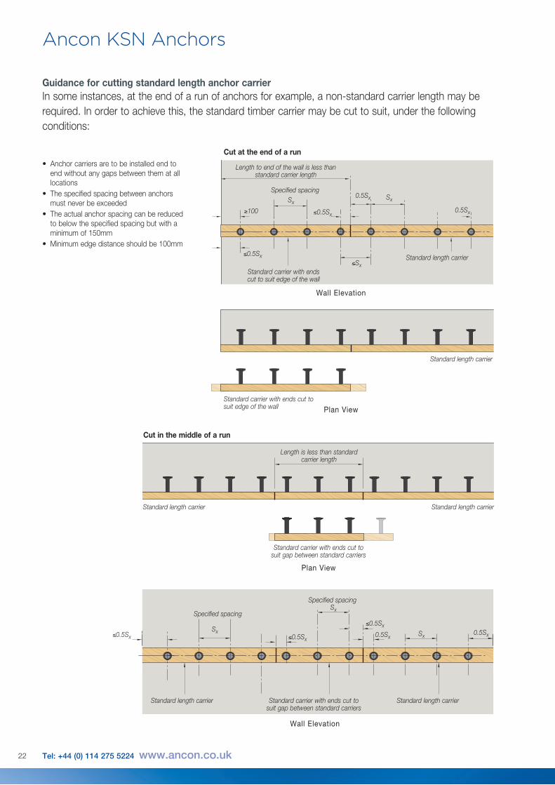
Guidance for cutting standard length anchor carrierIn some instances, at the end of a run of anchors for example, a non-standard carrier length may be required. In order to achieve this, the standard timber carrier may be cut to suit, under the following conditions:
• Anchor carriers are to be installed end to end without any gaps between them at all locations
• The specified spacing between anchors must never be exceeded
• The actual anchor spacing can be reduced to below the specified spacing but with a minimum of 150mm
• Minimum edge distance should be 100mm
Length to end of the wall is less than standard carrier length
Length is less than standard carrier length
Standard carrier with ends cut to suit gap between standard carriers
Standard carrier with ends cut to suit gap between standard carriers
Standard carrier with ends cut to suit edge of the wall
Standard length carrier
Standard length carrier Standard length carrier
Standard carrier with ends cut to suit edge of the wall
Cut in the middle of a run
Cut at the end of a run
Standard length carrier
Specified spacingSx
Sx
0.5Sx
0.5Sx
≤0.5Sx
≤0.5Sx≤Sx
≥100
Standard length carrier Standard length carrier
Specified spacing
Specified spacing
SxSx
Sx
0.5Sx0.5Sx≤0.5Sx
≤0.5Sx
≤0.5Sx
Wall Elevation
Wall Elevation
Plan View
Plan View
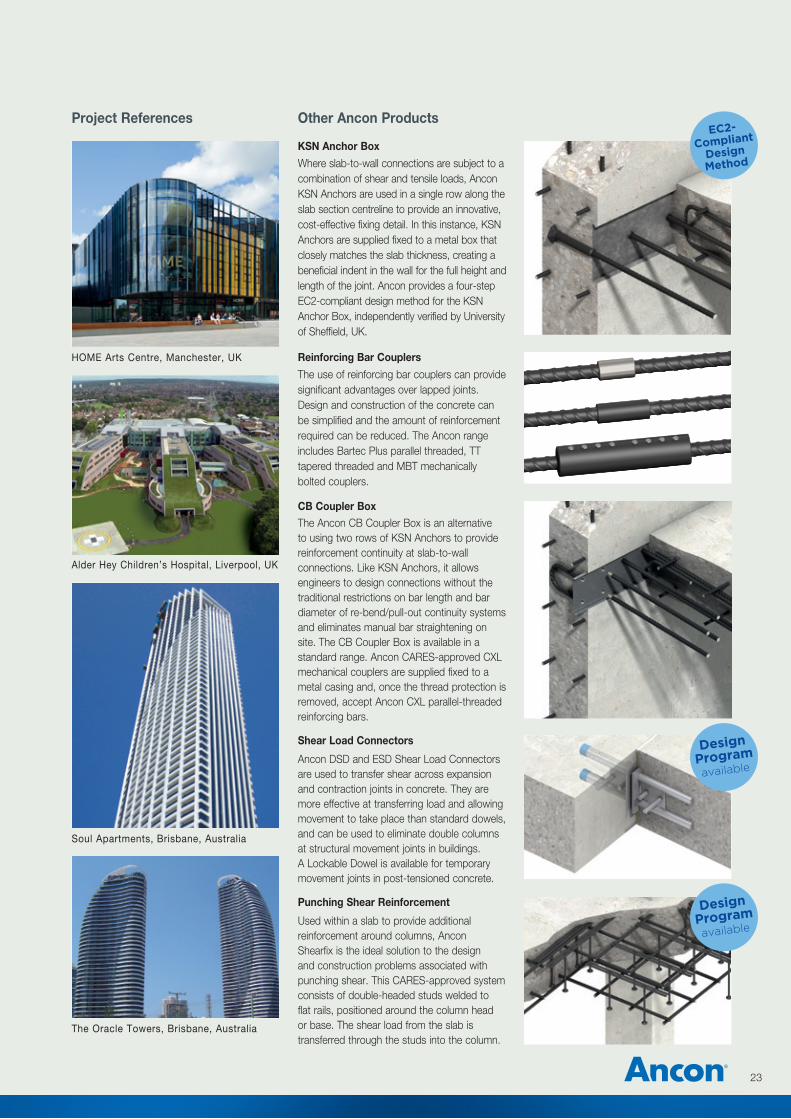
Reinforcing Bar Couplers
The use of reinforcing bar couplers can provide significant advantages over lapped joints. Design and construction of the concrete can be simplified and the amount of reinforcement required can be reduced. The Ancon range includes Bartec Plus parallel threaded, TT tapered threaded and MBT mechanically bolted couplers.
Shear Load Connectors
Ancon DSD and ESD Shear Load Connectors are used to transfer shear across expansion and contraction joints in concrete. They are more effective at transferring load and allowing movement to take place than standard dowels, and can be used to eliminate double columns at structural movement joints in buildings. A Lockable Dowel is available for temporary movement joints in post-tensioned concrete.
Punching Shear Reinforcement
Used within a slab to provide additional reinforcement around columns, Ancon Shearfix is the ideal solution to the design and construction problems associated with punching shear. This CARES-approved system consists of double-headed studs welded to flat rails, positioned around the column head or base. The shear load from the slab is transferred through the studs into the column.
CB Coupler BoxThe Ancon CB Coupler Box is an alternative to using two rows of KSN Anchors to provide reinforcement continuity at slab-to-wall connections. Like KSN Anchors, it allows engineers to design connections without the traditional restrictions on bar length and bar diameter of re-bend/pull-out continuity systems and eliminates manual bar straightening on site. The CB Coupler Box is available in a standard range. Ancon CARES-approved CXL mechanical couplers are supplied fixed to a metal casing and, once the thread protection is removed, accept Ancon CXL parallel-threaded reinforcing bars.
KSN Anchor Box
Where slab-to-wall connections are subject to a combination of shear and tensile loads, Ancon KSN Anchors are used in a single row along the slab section centreline to provide an innovative, cost-effective fixing detail. In this instance, KSN Anchors are supplied fixed to a metal box that closely matches the slab thickness, creating a beneficial indent in the wall for the full height and length of the joint. Ancon provides a four-step EC2-compliant design method for the KSN Anchor Box, independently verified by University of Sheffield, UK.
23
Other Ancon ProductsProject References
Soul Apartments, Brisbane, Australia
The Oracle Towers, Brisbane, Australia
EC2-
Compliant
Design
Method
Design
Program
available
Design
Program
available
Alder Hey Children’s Hospital, Liverpool, UK
HOME Arts Centre, Manchester, UK
Masonry Support Systems
Lintels
Windposts and Masonry Reinforcement
Wall Ties and Restraint Fixings
Channel and Bolt Fixings
Tension and Compression Systems
Insulated Balcony Connectors
Shear Load Connectors
Punching Shear Reinforcement
Reinforcing Bar Couplers
Reinforcement Continuity Systems
Stainless Steel Fabrications
Flooring and Formed Sections
Refractory Fixings
© Ancon
These products are available from:
This literature is printedon 80% recycled paper
80%
Ancon Building Products 98 Kurrajong Avenue Mount Druitt Sydney NSW 2770 Australia Tel: +61 (0) 2 8808 3100 Fax: +61 (0) 2 9675 3390 Email: [email protected] Visit: www.ancon.com.au
Ancon Building Products 2/19 Nuttall DriveHillsboroughChristchurch 8022New ZealandTel: +64 (0) 3 376 5205Fax: +64 (0) 3 376 5206Email: [email protected] Visit: www.ancon.co.nz
Ancon (Schweiz) AG Grenzstrasse 243250 LyssSwitzerland Tel: +41 (0) 31 750 3030 Fax: +41 (0) 31 750 3033 Email: [email protected] Visit: www.ancon.ch
Ancon Building Products GesmbH Puchgasse 1A-1220 ViennaAustria Tel: +43 (0) 1 259 58 62-0 Fax: +43 (0) 1 259 58 62-40 Email: [email protected] Visit: www.ancon.at
Ancon GmbH Bartholomäusstrasse 26 90489 Nuremberg Germany Tel: +49 (0) 911 955 1234 0 Fax: +49 (0) 911 955 1234 9 Email: [email protected] Visit: www.anconbp.de
Ancon Ltd President Way, President Park Sheffield S4 7UR United Kingdom Tel: +44 (0) 114 275 5224 Fax: +44 (0) 114 276 8543 Email: [email protected] Visit: www.ancon.co.uk
Ancon (Middle East) FZE PO Box 17225 Jebel Ali Dubai United Arab Emirates Tel: +971 (0) 4 883 4346 Fax: +971 (0) 4 883 4347 Email: [email protected] Visit: www.ancon.ae
The construction applications and details provided in this literature are indicative only. In every case, project working details should be entrusted to appropriately qualified and experienced persons.
Whilst every care has been exercised in the preparation of this document to ensure that any advice, recommendations or information is accurate, no liability or responsibility of any kind is accepted in respect of Ancon.
With a policy of continuous product development Ancon reserves the right to modify product design and specification without due notice.