Embed Size (px)
Citation preview

2017
ESK Komponenten für Kälte-, Klima- und Wärmepumpensysteme
ESK Components for cooling, air conditioning and heat pump systems

© 2014/2015/2016 ESK Schultze
Die Angaben dieser Broschüre entsprechen dem heutigen Stand unse rer Technik. Eine rechtliche Ver bind lichkeit kann aus den Anga ben nicht abgeleitet werden.
Der Nachdruck – auch auszugsweise – ist nur mit unserer Geneh mi gung erlaubt. Änderungen, die dem technischen Fortschritt dienen, behalten wir uns auch ohne Ankündigung vor.
The information given in this catalogue is based upon our present technology. A legaly liability can-not be derived from the technical specifications.
Reprints are only allowed with our per mission. ESK reserves the right to change technical specifi cations without prior notice, especially in the interest of product improvements.
Titelbild / cover picture: © paulrommer – stock.adobe.com
� www.esk-schultze.de CATALOGUE 2017
ALLGEMEINES GENERALEditorial Editorial 3
Unser Unternehmen Our company 4
Geschäftsfelder Business segments 5
Leistungsumfang Range of activities 5
Qualität Quality 6
Anwendungsbereiche unserer Produkte Application range 7
ESK Standard-Komponenten ESK standard components
ESK Komponenten für ESK components for ▪ Betriebsdrücke von 60 bar (-CDM) ▪ working pressures of 60 bar (-CDM) ▪ Betriebsdrücke von 130 bar (-CDH) ▪ working pressures of 130 bar (-CDH)
ESK-Empfehlungen für Ammoniak und Propan ESK ammonia and propane recommendations
Kältemaschinenöle Compressor oils 7
ESK-KOMPONENTEN ESK COMPONENTSÖlreguliersysteme – Oil control systems – Technische Hinweise und Systemdiagramme Technical references and flow diagrams 9
Ölabscheider Oil separators 18
Hochleistungs-Ölabscheider (BOS) High performance oil separators (BOS) 23
Ölabscheider-Sammler Oil separator reservoirs 30
Ölsammler Oil reservoirs 34Druckdifferenz- und Rückschlagventile Pressure and check valves 39
Ölspiegelregulatoren Oil level regulators 40Adaptersätze zur Regulatormontage Adapter kits for regulator installation 46Ölausgleichadapter Oil compensation adapters 47Absperrventilsätze Shut-off valve sets 48
Filter Strainer 49
Flüssigkeitsabscheider, Suction line accumulators,Multi-Flüssigkeitsabscheider Multi suction line accumulators 50
Filtertrockner Filter driers 57
Geräuschdämpfer Discharge line mufflers 58
Flüssigkeitssammler Liquid receivers 61
Füllstandskontrollen Level control 66
ESK Hinweise für Fluide der Gruppe 1 ESK References for hazardous fluids 70
ZUBEHÖR UND ERSATZTEILE ACCESSORIES AND SPARE PARTSVAFS Schwingungsdämpfung (60 bar) VAFS Vibration eliminators (60 bar) 73
Schaugläser Sight glasses 74
Heizelemente / Heizbänder Heater elements / Heater bands 76
Rota-Ventile und Fittings Rotalock valves and fittings 76
Schweißstutzen und -adapter Weld-solder connectors and adapters 77
Schwimmer-Flanschplatte Flange plate with float valve 78
Filterpatronen Replacement elements 78
Dichtungen und O-Ringe Gaskets and O-rings 79
ESK-PARTNER WELTWEIT ESK PARTNERS WORLDWIDE 80
1
MADE IN GERMANY
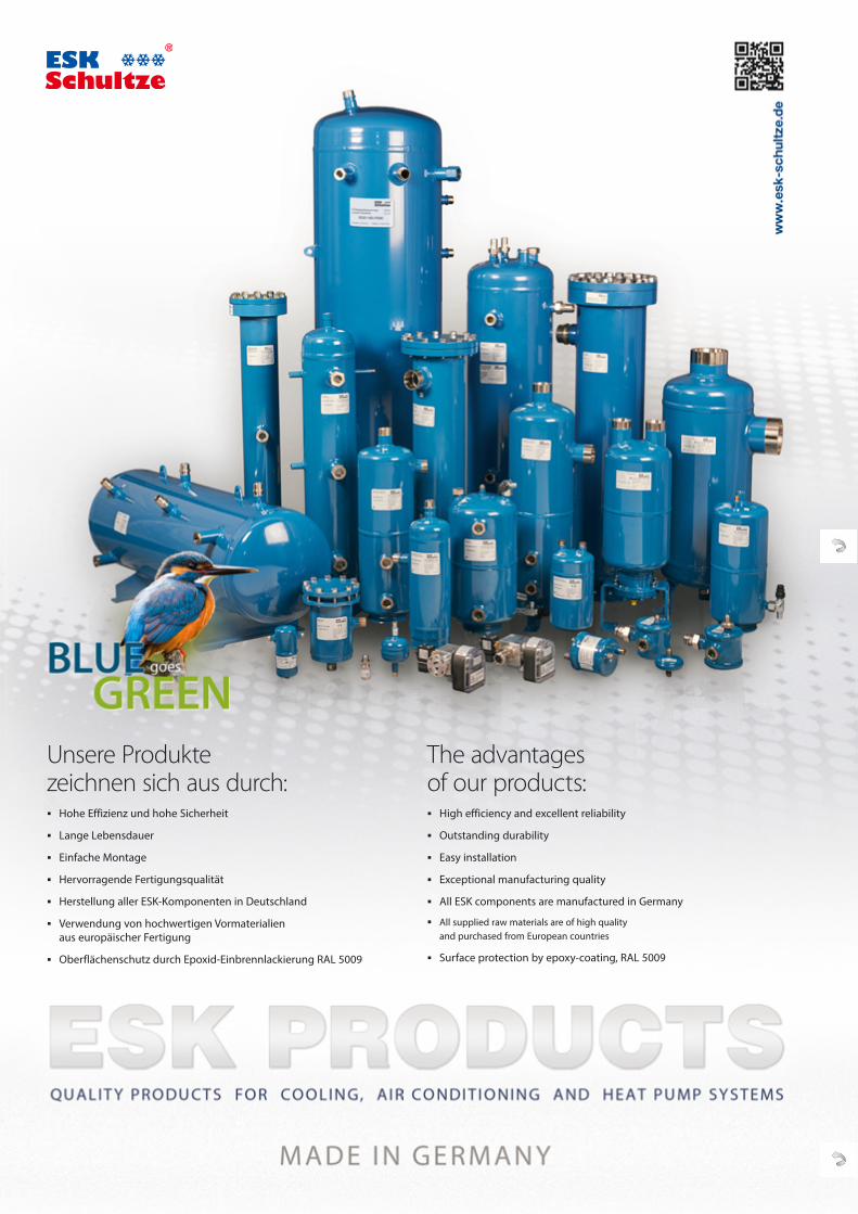
Unsere Produkte zeichnen sich aus durch:
Hohe Effizienz und hohe Sicherheit
Lange Lebensdauer
Einfache Montage
Hervorragende Fertigungsqualität
Herstellung aller ESK-Komponenten in Deutschland
Verwendung von hochwertigen Vormaterialien aus europäischer Fertigung
Oberflächenschutz durch Epoxid-Einbrennlackierung RAL 5009
The advantages of our products:
High efficiency and excellent reliability
Outstanding durability
Easy installation
Exceptional manufacturing quality
All ESK components are manufactured in Germany
All supplied raw materials are of high quality and purchased from European countries
Surface protection by epoxy-coating, RAL 5009
� www.esk-schultze.de CATALOGUE 2017
Editorial
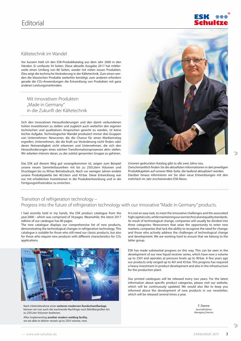
I had recently held in my hands, the ESK product catalogue from the year 2000 – which was comprised of 34 pages. Meanwhile, the latest 2017 edition of our catalogue has 80 pages.The new catalogue displays our comprehensive list of new products, demonstrating the technological changes in refrigeration technology. This catalogue is suitable for those who still need our classic products, but also for those who require new products with different characteristics for CO2 applications.
It is not an easy task, to meet the innovative challenges and the associated high capital costs, while maintaining our own technical and quality standards. As result of technological change, companies will usually be divided into three categories: Newcomers that seize the opportunity to enter new markets; companies that lack the ability to recognise the need for change; and those who actively address the challenges of technological change and development. We are working hard to ensure that we belong to the latter group.
ESK has made substantial progress on this way. This can be seen in the development of our new liquid receiver series, which have now a volume up to 250 l and operates at pressure levels up to 90 bar. A few years ago our products only ranged up to 40 l and 45 bar. This progress has required a heavy investment in product development and also in the infrastructure for the production plant.
Our printed catalogues will be released every two years. For the latest information about specific product categories, please visit our website, which will be continuously updated. We would also like to keep you informed about the development of new products in our newsletter, which will be released several times a year.
F. DanneGeschäftsführer
Managing Director
Transition of refrigeration technology – Progress into the future of refrigeration technology with our innovative “Made in Germany” products.
Kältetechnik im Wandel
Vor kurzem hielt ich den ESK-Produktkatalog aus dem Jahr 2000 in den Händen. Er umfasste 34 Seiten. Diese aktuelle Ausgabe 2017 hat mittler-weile einen Umfang von 80 Seiten, wieder mit vielen neuen Produkten. Dies zeigt die technische Veränderung in der Kältetechnik. Zum einen wer-den die klassischen Produkte weiterhin benötigt, zum anderen erfordern gerade die CO2-Anwendungen die Entwicklung von Produkten mit ganz anderen Leistungsmerkmalen.
Mit innovativen Produkten „Made in Germany“ in die Zukunft der Kältetechnik
Sich den innovativen Herausforderungen und den damit verbundenen hohen Investitionen zu stellen und zugleich auch weiterhin den eigenen technischen und qualitativen Ansprüchen gerecht zu werden, ist keine leichte Aufgabe. Technologischer Wandel produziert immer drei Gruppen von Unternehmen: Newcomer, die die Chance für einen Markteinstieg ergreifen, Unternehmen, die die Kraft zur Veränderung nicht finden oder deren Notwendigkeit nicht erkennen und Unternehmen, die sich den Herausforderungen eines solchen Transformationsprozesses aktiv stellen. Wir arbeiten intensiv daran, zu der zuletzt genannten Gruppe zu gehören.
Das ESK auf diesem Weg gut vorangekommen ist, zeigen zum Beispiel unsere neuen Sammlerbaureihen mit bis zu 250 Litern Volumen und Druck lagen bis zu 90 bar Betriebsdruck. Noch vor wenigen Jahren endete unsere Produktpalette bei 40 Litern und 45 bar. Diese Entwicklung war nur mit erheblichen Investitionen in die Produktentwicklung und in die Fertigungsinfrastruktur zu erreichen.
Unseren gedruckten Katalog gibt es alle zwei Jahre neu. Zwischenzeitlich finden Sie die aktuellsten Informationen in den jeweiligen Produktkapiteln auf unserer Web-Seite, die laufend aktualisiert werden. Darüber hinaus informieren wir Sie über neue Entwicklungen mit den mehrfach im Jahr erscheinenden ESK-News.
Nach Inbetriebnahme einer weiteren modernen Rundschweißanlage können wir nun auch die wachsende Nachfrage nach Behältergrößen bis zu 250 Liter Volumen bedienen.
After implementing another modern welding facility, we are able to deliver vessels up to 250 l volume, now.
3
KATALOG 2017 � www.esk-schultze.de
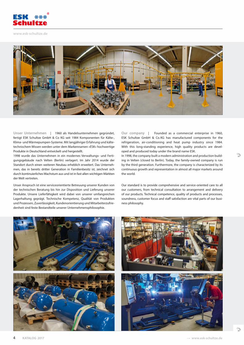
Unser Unternehmen | 1960 als Handelsunternehmen gegründet, fertigt ESK Schultze GmbH & Co KG seit 1984 Komponenten für Kälte-, Klima- und Wärmepumpen-Systeme. Mit langjähriger Erfahrung und kälte-technischem Wissen werden unter dem Markennamen »ESK« hochwertige Produkte in Deutschland entwickelt und hergestellt. 1998 wurde das Unternehmen in ein modernes Verwaltungs- und Ferti-gungs gebäude nach Velten (Berlin) verlagert. Im Jahr 2014 wurde der Standort durch einen weiteren Neubau erheblich erweitert. Das Unterneh-men, das in bereits dritter Generation in Familienbesitz ist, zeichnet sich durch kontinuierliches Wachstum aus und ist in fast allen wichtigen Märkten der Welt vertreten.
Unser Anspruch ist eine serviceorientierte Betreuung unserer Kunden von der technischen Beratung bis hin zur Disposition und Lieferung unserer Produkte. Unsere Lieferfähigkeit wird dabei von unserer umfangreichen Lagerhaltung geprägt. Technische Kompetenz, Qualität von Produkten und Prozessen, Zuverlässigkeit, Kundenorientierung und Mitarbeiterzufrie-denheit sind feste Bestandteile unserer Unternehmensphilosophie.
Our company | Founded as a commercial enterprise in 1960, ESK Schultze GmbH & Co. KG has manufactured components for the refrigeration, air-conditioning and heat pump industry since 1984. With this long-standing experience, high quality products are devel-oped and produced today under the brand name ESK. In 1998, the company built a modern administration and production build-ing in Velten (closed to Berlin). Today, the family-owned company is run by the third generation. Furthermore, the company is characterized by its continuous growth and representation in almost all major markets around the world.
Our standard is to provide comprehensive and service-oriented care to all our customers, from technical consultation to arrangement and delivery of our products. Technical competence, quality of products and processes, soundness, customer focus and staff satisfaction are vital parts of our busi-ness philosophy.
4
www.esk-schultze.de
� www.esk-schultze.de CATALOGUE 2017
Geschäftsfelder | ESK bedient zwei unterschiedliche Geschäftsfelder:
1. Über unsere meist sehr langjährigen Handelspartner in aller Welt sind unsere Standardprodukte in über 50 Ländern verfügbar. Diese umfassen eine sehr breite Produktpalette und sind im vorliegenden Katalog und auf unseren Web-Seiten technisch detailliert dokumentiert. Unser Pro-duktportfolio wird laufend auf der Grundlage der Marktnachfrage und neuesten technischen Entwicklungen aktualisiert und erweitert.
2. Wir sind Erstausrüster (OEM)-Lieferant für wichtige Anlagenbauer in den Geschäftsfeldern Supermarktkälte, Fahrzeugkälte und Wärmepumpen. Hier lassen sich die traditionellen ESK-Qualitäten wie Liefertreue, sinn-volle Lagerkonzepte, hohe Material- und Fertigungsqualität optimal mit der hohen Beratungskompetenz im Hause sowie der ausgeprägten Kundenorientierung verbinden.
Ein umfangreicher Materialbaukasten und automatisierte Fertigungsver-fahren erlauben die Fertigung nach Kundenwünschen von Komponenten von 0,3 bis 250 Litern Volumen in den unterschiedlichsten Drucklagen bis zu 130 bar. Unsere Vertriebsmitarbeiter beraten Sie gern.
Leistungsumfang | Unser volles Leistungsspektrum sehen wir nicht aus-schließlich in der Herstellung und Lieferung von kältetechnischen Kompo-nenten, sondern insbesondere in unserer allgemeinen technischen Kom-petenz – sowohl in der Entwicklung als auch im Vertrieb. Wir bieten neben einer bedarfsgerechten, technisch optimierten Angebotslegung auch die Schnittstellenanbindung an Ihre Abläufe in der Produktentwicklung und im Einkauf an. Nutzen Sie insbesondere unsere Kenntnisse in der Auslegung von Ölmanagementsystemen. Die bei ESK übliche hohe und schnelle Verfügbarkeit im Standardprogramm wird mit der Möglichkeit individuell abgestimmter Lieferprozesse, zum Beispiel innerhalb von Rah-menaufträgen, ergänzt. Der Export in über 50 Länder und in alle Kontinente der Welt verdeutlicht unsere Wettbewerbsfähigkeit und hohe Flexibilität.
Business segments ESK primarily serves two different business segments:
1. Our standard products are available in more than 50 countries by mostly long-time trading partners. This includes a wide range of products. Also they are technically and accurately documented in this catalog and our website. Our portfolio will be constantly updated, based on the market demand and the latest technical developments.
2. We are original equipment manufacturer (OEM) supplier for important system firms in the fields of supermarket refrigeration, vehicle refrig-eration and heat pumps. This allows us the optimal combination of traditional ESK qualities such as delivery reliability, reasonable storage concepts, high material and manufacturing quality together with excel-lent advisory skills and superior customer focus.
An extensive material modular and automated manufacturing process allows the production according to customer choice. The choices of com-ponents are available from 0.3 L to 250 L volume with different pressure levels up to 130 bar. Our sales staffs would be pleased to assist you.
Range of activities | We do not exclusively consider our full range of services just by manufacturing and supplying cooling components, but especially also in our general technical expertise regarding development and sales. In addition to a demand-oriented, technically opted listing interpretation, we also offer an interface to your product development and buying processes. ESK’s traditional high and fast availability regarding the standard pro-gram is supplemented with the facility of individually matched delivery processes within e.g. frame orders. The fact that we export to more than 50 countries and to all continents illustrates our competitiveness as well as our high flexibility.
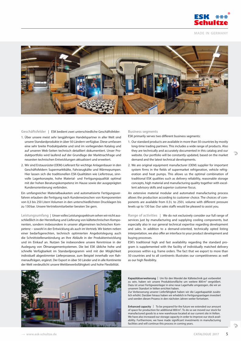
Kapazitätserweiterung | Um für den Wandel der Kältetechnik gut vorbereitet zu sein, haben wir unsere Produktionsfläche um weitere 800 m2 vergrößert. Dazu ist unser Fertigwarenlager in eine neue Lagerhalle umgezogen, die wir an unserem Standort in Velten errichtet haben. Zur Verbesserung unserer Lieferfähigkeit haben wir die Lagerkapazität zusätz-lich erhöht. Darüber hinaus haben wir erheblich in Fertigungsanlagen investiert und werden diesen Prozess in den nächsten Jahren weiter fortsetzen.
Enhanced capacity | To be prepared for the future we extended our amount of space for production for additional 800 m2. To do so we moved our stock for manufactured goods to a new warehouse located at our current site in Velten. We have also increased our storage capacity in order to improve our stock avail-ability. Furthermore, we have made significant investments in manufacturing facilities and will continue this process in coming years.
5
MADE IN GERMANY
KATALOG 2017 � www.esk-schultze.de
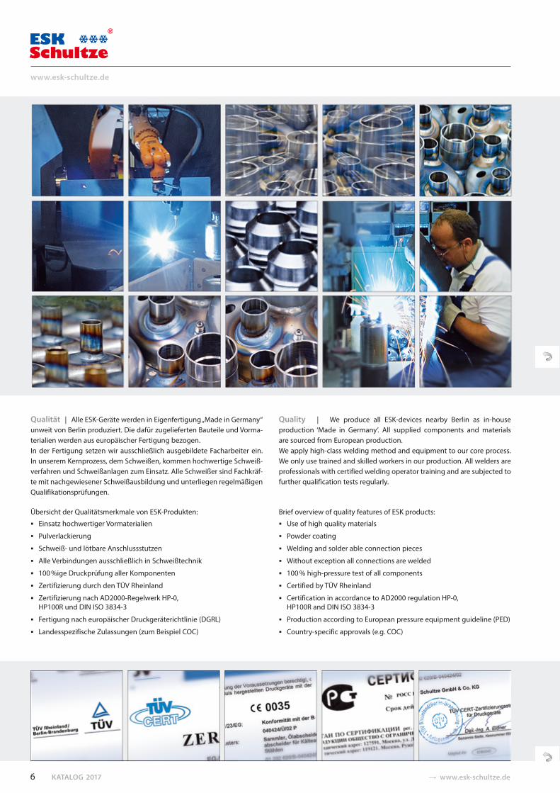
Qualität | Alle ESK-Geräte werden in Eigenfertigung „Made in Germany“ unweit von Berlin produziert. Die dafür zugelieferten Bauteile und Vorma-terialien werden aus europäischer Fertigung bezogen. In der Fertigung setzen wir ausschließlich ausgebildete Facharbeiter ein. In unserem Kernprozess, dem Schweißen, kommen hochwertige Schweiß-verfahren und Schweißanlagen zum Einsatz. Alle Schweißer sind Fachkräf-te mit nachgewiesener Schweißausbildung und unterliegen regelmäßigen Qualifikationsprüfungen.
Übersicht der Qualitätsmerkmale von ESK-Produkten:
Einsatz hochwertiger Vormaterialien
Pulverlackierung
Schweiß- und lötbare Anschlussstutzen
Alle Verbindungen ausschließlich in Schweißtechnik
100 %ige Druckprüfung aller Komponenten
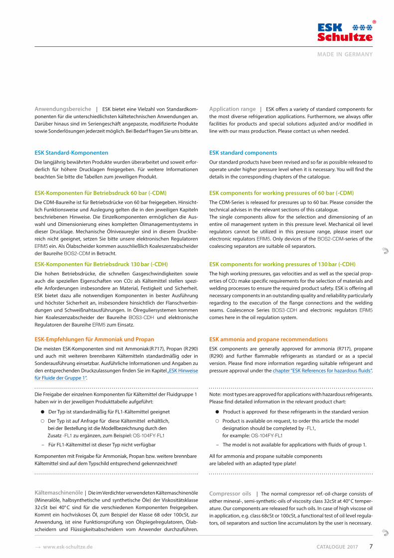
Zertifizierung durch den TÜV Rheinland
Zertifizierung nach AD2000-Regelwerk HP-0, HP100R und DIN ISO 3834-3
Fertigung nach europäischer Druckgeräterichtlinie (DGRL)
Landesspezifische Zulassungen (zum Beispiel COC)
Quality | We produce all ESK-devices nearby Berlin as in-house production ‘Made in Germany’. All supplied components and materials are sourced from European production. We apply high-class welding method and equipment to our core process. We only use trained and skilled workers in our production. All welders are professionals with certified welding operator training and are subjected to further qualification tests regularly.
Brief overview of quality features of ESK products:
Use of high quality materials
Powder coating
Welding and solder able connection pieces
Without exception all connections are welded
100 % high-pressure test of all components
Certified by TÜV Rheinland
Certification in accordance to AD2000 regulation HP-0, HP100R and DIN ISO 3834-3
Production according to European pressure equipment guideline (PED)
Country-specific approvals (e.g. COC)
6
www.esk-schultze.de
� www.esk-schultze.de CATALOGUE 2017
Anwendungsbereiche | ESK bietet eine Vielzahl von Standardkom-ponenten für die unterschiedlichsten kältetechnischen Anwendungen an. Darüber hinaus sind im Seriengeschäft angepasste, modifizierte Produkte sowie Sonderlösungen jederzeit möglich. Bei Bedarf fragen Sie uns bitte an.
ESK Standard-Komponenten
Die langjährig bewährten Produkte wurden überarbeitet und soweit erfor-derlich für höhere Drucklagen freigegeben. Für weitere Informationen beachten Sie bitte die Tabellen zum jeweiligen Produkt.
ESK-Komponenten für Betriebsdruck 60 bar (-CDM)
Die CDM-Baureihe ist für Betriebsdrücke von 60 bar freigegeben. Hinsicht-lich Funktionsweise und Auslegung gelten die in den jeweiligen Kapiteln beschriebenen Hinweise. Die Einzelkomponenten ermöglichen die Aus-wahl und Dimensionierung eines kompletten Ölmanagementsystems in dieser Drucklage. Mechanische Ölniveauregler sind in diesem Druckbe-reich nicht geeignet, setzen Sie bitte unsere elektronischen Regulatoren ERM5 ein. Als Ölabscheider kommen ausschließlich Koaleszenzabscheider der Baureihe BOS2-CDM in Betracht.
ESK-Komponenten für Betriebsdruck 130 bar (-CDH)
Die hohen Betriebsdrücke, die schnellen Gasgeschwindigkeiten sowie auch die speziellen Eigenschaften von CO2 als Kältemittel stellen spezi-elle Anforderungen insbesondere an Material, Festigkeit und Sicherheit. ESK bietet dazu alle notwendigen Komponenten in bester Ausführung und höchster Sicherheit an, insbesondere hinsichtlich der Flanschverbin-dungen und Schweißnahtausführungen. In Ölreguliersystemen kommen hier Koaleszenzabscheider der Baureihe BOS3-CDH und elektronische Regulatoren der Baureihe ERM5 zum Einsatz.
ESK-Empfehlungen für Ammoniak und Propan
Die meisten ESK-Komponenten sind mit Ammoniak (R 717), Propan (R 290) und auch mit weiteren brennbaren Kältemitteln standardmäßig oder in Sonderausführung einsetzbar. Ausführliche Informationen und Angaben zu den entsprechenden Druckzulassun gen finden Sie im Kapitel „ESK Hinweise für Fluide der Gruppe 1“.
Die Freigabe der einzelnen Komponenten für Kältemittel der Fluidgruppe 1haben wir in der jeweiligen Produkttabelle aufgeführt:
● Der Typ ist standardmäßig für FL1-Kältemittel geeignet
○ Der Typ ist auf Anfrage für diese Kältemittel erhältlich, bei der Bestellung ist die Modellbezeichnung durch den
Zusatz -FL1 zu ergänzen, zum Beispiel: OS-104FY-FL1
– Für FL1-Kältemittel ist dieser Typ nicht verfügbar
Komponenten mit Freigabe für Ammoniak, Pro pan bzw. weitere brennbare Kältemittel sind auf dem Typschild entsprechend gekennzeichnet!
Kältemaschinenöle | Die im Verdichter verwendeten Kältemaschinenöle (Mineralöle, halbsynthetische und synthetische Öle) der Viskositäts klasse 32 cSt bei 40° C sind für die verschiedenen Komponenten freigegeben. Kommt ein hochviskoses Öl, zum Beispiel der Klasse 68 oder 100cSt, zur Anwendung, ist eine Funktionsprüfung von Ölspiegelregulatoren, Ölab-scheidern und Flüssigkeitsabscheidern vom Anwender durchzuführen.
Application range | ESK offers a variety of standard components for the most diverse refrigeration applications. Furthermore, we always offer facilities for products and special solutions adjusted and/or modified in line with our mass production. Please contact us when needed.
ESK standard components
Our standard products have been revised and so far as possible released to operate under higher pressure level when it is necessary. You will find the details in the corresponding chapters of the catalogue.
ESK components for working pressures of 60 bar (-CDM)
The CDM-Series is released for pressures up to 60 bar. Please consider the technical advises in the relevant sections of this catalogue. The single components allow for the selection and dimensioning of an entire oil management system in this pressure level. Mechanical oil level regulators cannot be utilized in this pressure range, please insert our electronic regulators ERM5. Only devices of the BOS2-CDM-series of the coalescing separators are suitable oil separators.
ESK components for working pressures of 130 bar (-CDH)
The high working pressures, gas velocities and as well as the special prop-erties of CO2 make specific requirements for the selection of materials and welding processes to ensure the required product safety. ESK is offering all necessary components in an outstanding quality and reliability particularly regarding to the execution of the flange connections and the welding seams. Coalescence Series BOS3-CDH and electronic regulators ERM5 comes here in the oil regulation system.
ESK ammonia and propane recommendations
ESK components are generally approved for ammonia (R717), propane (R290) and further flammable refrigerants as standard or as a special version. Please find more information regarding suitable refrigerant and pressure approval under the chapter “ESK References for hazardous fluids“.
Note: most types are approved for applications with hazardous refrigerants. Please find detailed information in the relevant product chart:
● Product is approved for these refrigerants in the standard version
○ Product is available on request, to order this article the model designation should be completed by -FL1,
for example: OS-104FY-FL1
– The model is not available for applications with fluids of group 1.
All for ammonia and propane suitable components are labeled with an adapted type plate!
Compressor oils | The normal compressor ref.-oil-charge consists of either mineral-, semi-synthetic-oils of viscosity class 32cSt at 40° C temper-ature. Our components are released for such oils. In case of high viscose oil in application, e.g. class 68cSt or 100cSt, a functional test of oil level regula-tors, oil separators and suction line accumulators by the user is necessary.
7
MADE IN GERMANY
CO
MP
ON
EN
TS
ESK-KOMPONENTEN Ölreguliersysteme – Technische Hinweise und Systemdiagramme 9
Ölabscheider 18
Hochleistungs-Ölabscheider (BOS) 23
Ölabscheider-Sammler 30 NEU: Baureihe BOS3-R-CDH (PS max: 130 bar) 33
Ölsammler 34Druckdifferenz- und Rückschlagventile 39
Ölspiegelregulatoren 40 NEU: Baureihe ERM5 42Adaptersätze zur Regulatormontage 46Ölausgleichadapter 47Absperrventilsätze 48
Filter 49
Flüssigkeitsabscheider, Multi-Flüssigkeitsabscheider 50 NEU: Baureihe FA2-CD (PS max: 45 bar) 56
Filtertrockner 57
Geräuschdämpfer 58
Flüssigkeitssammler 61 NEU: Baureihe S / SGS-CD für R410A / R744 (PS max: 45 bar) 63 NEU: Baureihe SGS-PS90 (PS max: 90 bar) mit Behältergrößen bis 250 Liter 65
Füllstandskontrollen 66 NEU: Typ LC-CDH (PS max: 130 bar)
ESK Hinweise für Fluide der Gruppe 1 70
ESK COMPONENTSOil control systems– Technical references and flow diagrams 9
Oil separators 18
High performance oil separators (BOS) 23
Oil separator reservoirs 30 NEW: Series BOS3-R-CDH (PS max: 130 bar) 33
Oil reservoirs 34Pressure and check valves 39
Oil level regulators 40 NEW: Types ERM5 42Adapter kits for regulator installation 46Oil compensation adapters 47Shut off valve sets 48
Strainer 49
Suction line accumulators,Multi suction line accumulators 50 NEW: Series FA2-CD (PS max: 45 bar) 56
Filter driers 57
Discharge line mufflers 58
Liquid receivers 61 NEW: Series S / SGS-CD for R410A / R744 (PS max: 45 bar) 63 NEW: Series SGS-PS90 (PS max: 90 bar) vessels up to 250 litres volume 65
Level control 66 NEW: Type LC-CDH (PS max: 130 bar)
ESK References for hazardous fluids 70

� www.esk-schultze.de CATALOGUE 2017
ÖlreguliersystemeVerdichter-Verbundschaltungen sind durch die Anwendung mehrerer Ver-dichter in einem Kältekreislauf gekennzeichnet. Der Verbundbetrieb bietet für den Betreiber folgende Vorteile:
Große Kälteleistungsbereiche können mit wenigen Verdichtermodellen abgedeckt werden.Ideale Leistungsregelung durch das Abschaltenvon Verdichtern bei hoher Leistungszahl.EnergieeinsparungAusreichende Kühlleistung bei Ausfall eines VerdichtersUnkomplizierte Anlaufstrombegrenzung Platzsparende AnlagenkonzeptionStandardisierte Serienfertigung ermöglicht eine optimaleAuswahl der Komponenten und deren Montage
Öl in VerbundsystemenDie vom einzelnen Verdichter in das System geförderte Öl men ge (Ölwurf ) muss dem jeweiligen Verdichter bei allen möglichen Betriebs be din gun gen in gleicher Menge wieder zugeführt werden. Teillastbetrieb, lange Lei tungs -wege, hohe Kälte mit tel mengen und geringfügige Herstellungs tole ranzen der Ver dich ter erfordern die Regelung des Ölstandes im Kurbel gehäuse.
Ölstand-Reguliersysteme übernehmen diese Regelung und arbeiten pro-blemlos in der täglichen Praxis. Komplexe Ver roh rungen ohne Regel funk-tion sind nicht mehr erforderlich.
Als zuverlässige technische Lösung haben sich Ölreguliersys teme in der Praxis bewährt. ESK-Ölreguliersysteme er mög li chen die Vorteile des Ver-bundbetriebes bei höchstmöglicher Anlagensicherheit zu nutzen. Beim Verbund verschiedener Verdichtermodelle, zweistufiger Verdichter und Anlagen mit sogenannten Satelliten Verdichtern ist die Überwachung und Regelung der Ölstände in den Verdichtern über ein Regulier system uner-lässlich. In den letzten Jahren wurden neben der klassischen Ausführung der Ölreguliersysteme mit einem Nie der druck-Ölreservoir auch Systeme mit Hoch druck-Reservoir eingesetzt.
Steigerung der Energieeffizienz durch ÖlreguliersystemeDer Verbundanlagenbau kann aufgrund allgemeiner Empfeh lungen unter-schiedlich ausgeführt werden. Kosten güns ti ge Ausführungen basieren auf idealisierten Annah men. In rea ler Anwendung, wie zum Beispiel im Bereich der Super markt kühl anlagen mit einem komplexen und langen Rohr lei-tungs netz, großen Kältemittelfüllmengen und häufigem Teil last betrieb, lie-gen Bedingungen vor, die sich erheblich vom Ideal unterscheiden können.
Beim Einsatz eines saugseitigen Verteilers anstelle eines Öl re guliersystems spart man pro Verbundsatz 600 bis 800 € an Investitionskosten. Während der Inbetriebnahme oder im Servicefall werden zu geringe oder unter-schiedliche Öl stände in den Verdichtern, bedingt durch Ver dichter-Fer ti-gungstoleranzen und Laufzeitdifferenzen, durch wieder ho len des Auf füllen von Öl ausgeglichen. Nach Sätti gung der Anlage mit Öl ist ein nicht effi-zienter Betrieb bei vari ieren den Betriebsbedingungen ermöglicht.
Einflüsse von Kältemaschinenöl im KältekreislaufEine hinreichende Schmierung der Verdichter mit einem Kälte maschi nenöl ist zwingend erforderlich, um Schädi gun gen oder Zerstörungen durch erhöhten Verschleiß der Ma schi nen zu vermeiden. Dabei ist es nicht zu ver-hindern, dass eine geringe Menge Öl, etwa 1 – 3 Prozent des Kälte mittel-Massenstroms, über den Verdichter in den Kälte mit tel kreis lauf gelangt.
Schon geringe Mengen Öl im Kältemittelmassenstrom können die Ursache für einen Anstieg des Kondensations druckes (pc) im Verflüssiger sein [1]. Eine Verschlechterung des Wärmeübergangs durch Öl im Verdampfer führt zu tie fe ren Verdampfungstemperaturen, was einen geringeren Druck auf der Saugseite (Verdampfungsdruck p0) des Kälte kreislaufs bedeutet. Das erhöhte Verhältnis von pc / p0 führt zu einer Reduzierung des Verdichter-Liefergrades, was bei geringerer Kälteleistung verlängerte Laufzeiten der Kälte mit telverdichter zur Folge hat [2].
Oil control systemsModern refrigeration plants often utilizes two or more compressors in parallel. This offers many advantages to the user, including:
Vast capacity ranges can be coveredby few compressor modelsOptimal capacity control and capabilityfor high energy efficiencyEnergy savingBack-up capacity in the event of one compressor failingComparatively easy starting characteristicsSpace saving, compact construction Serial production, enables an optimal selectionof com ponents and their installation.
Oil in parallel compressor systemsThe oil quantity carried over by an individual compressor in parallel systems must be returned in the same quantity under all operating conditions. Part load, long piping, high refrigerant charge and manufacturer toler-ances of compressors makes the control of crank case oil level necessary.
Oil control systems provides this control and works reliable. It makes complex piping and valving unnecessary.
ESK oil systems make it possible to utilize the advantages of parallel com-pressor plant to the maximum whilst maintaining the safety and reliability requirement.
Oil control systems are essential to control and watch oil levels if different compressor models, two-stage compressors and so called systems with sat-ellite compressors are involved. In the past years, beside the classic design of oil system with low pressure oil reservoir, systems with high pressure oil reservoirs are used.
Energy efficiency increase by using oil control systemsThe construction of multiple compressor racks can be executed variably due to general recommendations. Low cost solutions are based on idealized assumptions. In real applications, such as in the supermarket area with a complex and long distance piping network, large refrigerant charges and frequent part-load conditions are conditions which considerably differ from the ideal.
Systems with a suction header instead of an oil control system save, on the average, approx. 600 – 800 € per pack on investment. During commission-ing of the system or when servicing, too low oil levels in the compressor crankcases are compensated by repeatingly charging additional oil. The different oil levels are a result of compressor tolerances as well as various operating conditions. After a system saturation with oil, a non-efficient operation is possible at various conditions.
Influence of oil in the refrigeration cycleAn adequate lubrication of the compressor with an refrigerating oil is obligatory to avoid damages by wear of bearings, pistons, connecting rods and crankshaft. Thereby, ref.-compressors unavoidably have an oil carry over rate of approx. 1–3 % of refrigeration mass flow.
Small amounts of oil can already be the reason for an increase of the con-densing pressure (pc). A deterioration of the heat transfer in the evaporator caused by oil will lead to lower evaporating pressure (p0).
The rise of the pressure ratio pc/p0 has a negative impact on the volu-metric efficiency. The system operation time increases in respect of the compressorcapacity reduction.
Technische Hinweise – ÖlreguliersystemeTechnical references – Oil control systems
9
MADE IN GERMANY
KATALOG 2017 � www.esk-schultze.de
Steigt der Energiebedarf durch das „Verölen” der An la gen nur um zwei Prozent, haben sich die Ölregulier sys teme bereits nach einem Jahr amortisiert.
ESK-Ölreguliersystem mit Niederdruck ÖlreservoirDas System setzt sich aus folgenden ESK-Komponenten zusammen:
ESK-Ölabscheider ESK-Druckdifferenzventil
ESK-Ölsammler ESK-Filter
ESK-Ölspiegelregulatoren ESK-Flüssigkeits- bzw. Multiabscheider
ESK-Ö lreguliersystem mit Hochdruck ÖlreservoirDas System setzt sich aus folgenden ESK-Komponenten zusammen:
ESK- Ölabscheider-Sammler
ESK- Ölspiegelregulatoren, elektronisch
ESK- Filter
ESK- Flüssigkeits- bzw. Multiabscheider
Bei Hochdrucksystemen wird Öl mit hoher Temperatur und ei ner erhebli-chen Entmischung (Schaumbildung) über einen elek tro ni schen Regulator zugeführt. Mechanische Regulatoren sind für An wendungen mit Druck-differenzen > 6 bar nicht mehr einsetzbar.
Bei Niederdrucksystemen wird das Öl im Ölsammler abge kühlt, entspannt und entgast. Ein Regulator, mechanisch oder elektro nisch, führt dem Ver-dichter Öl ohne weitere Entmischung zu. Die Anordnung der Kompo nen-ten und deren Auslegung werden im folgenden beschrieben.
If the energy demand increases only by 2 % due to a higher oil saturation of a system, the OCS has already amortized itself after the first year.
ESK Oil control system with low pressure reservoirThe system consists of the following ESK-components:
ESK Oil separators ESK Pressure valve
ESK Reservoir ESK Strainers
ESK Oil level regulators ESK Suction line- and multi accumulators
ESK oil control system with high pressure reservoir The system consist of the following components:
ESK Oil separator reservoir
ESK Oil level regulator, electronic
ESK Strainer
ESK Suction line- and multi accumulators
In high pressure systems oil will feed into crankcase by means of an elec-tronic regulator. Extreme reduction of ref. concen tra tion will lead into strong foam formation. Mechanical regulators are not applicable if pres-sure difference will exceed 6 bar.
In low pressure systems the oil will be cooled down, refrigerant in oil will boiled off. An oil level regulator, mechanical or electronic feed the com-pressor without a remarkable change of ref. concentration. The combina-tion and selection of components are described on the following pages.
Anwendung von ÖlreguliersystemenDurch den Einsatz eines Ölreguliersystems, bestehend aus Ölabscheider, Ölsammler und Ölspiegelregulator werden eine Reihe von positiven Eigen-schaften hinsichtlich Zuver läs sigkeit und Energieeinsparung erreicht.
Durch den Einsatz eines Ölabscheiders kann das in den Kälte mittel-Mas sen -strom gelangte Öl fast vollständig abge schieden werden. Dadurch steigt der COP der Anlage. Weiterhin wird eine geringere Verdichterlaufzeit er-reicht, was den Energieverbrauch der Anlage und die indirekte CO2-Emis-sion reduziert.
Der Ölsammler erfüllt wichtige Funktionen hinsicht lich der Verbesse rung der Eigenschaften des Kälte ma schi nen öls vor der „Wiederver wend ung“. Über ein Druckdif fe renz ventil wird ein Druck mit Δ p =1,5 bar über Saug druck eingestellt. Durch den Druckabfall von Konden sations druck zum Sammler-druck entmischt sich im Öl gelöstes Kälte mit tel und entweicht zur Saugseite. Weiter hin kann das heiße abgeschiedene Öl im Samm ler abkühlen. Die Entmi-schung und die Abkühlung wirken sich positiv auf Schmier eigen schaf ten des Öls aus. In Verbindung mit den Ölspiegel re gu la toren wird die Versor-gung mit Öl und die optimale Rege lung des Ölstandes auf Mitte Schauglas der Verdichter gesichert. Durch den Einsatz von Ölreguliersystemen können somit Wer te geschützt und zusätzliche Kosten vermieden werden.
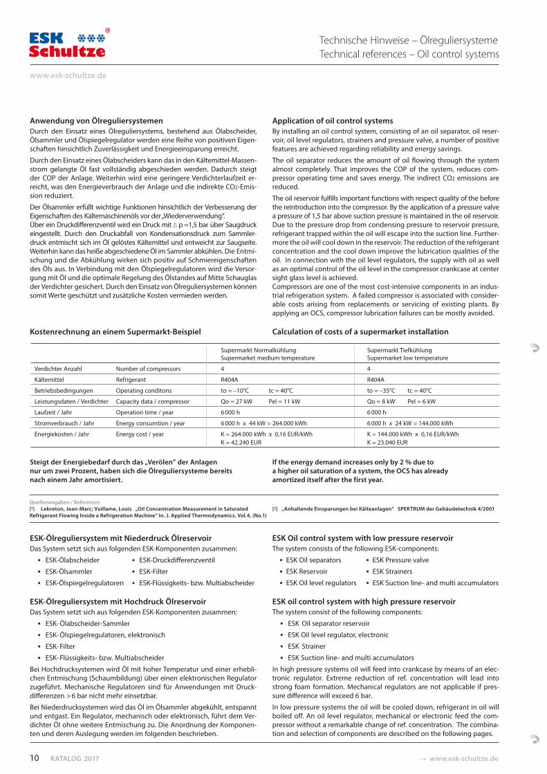
Kostenrechnung an einem Supermarkt-Beispiel
Application of oil control systemsBy installing an oil control system, consisting of an oil separator, oil reser-voir, oil level regulators, strainers and pressure valve, a number of positive features are achieved regarding reliability and energy savings.
The oil separator reduces the amount of oil flowing through the system almost completely. That improves the COP of the system, reduces com-pressor operating time and saves energy. The indirect CO2 emissions are reduced.
The oil reservoir fulfills important functions with respect quality of the before the reintroduction into the compressor. By the application of a pressure valve a pressure of 1,5 bar above suction pressure is maintained in the oil reservoir. Due to the pressure drop from condensing pressure to reservoir pressure, refrigerant trapped within the oil will escape into the suction line. Further-more the oil will cool down in the reservoir. The reduction of the refrigerant concentration and the cool down improve the lubrication qualities of the oil. In connection with the oil level regulators, the supply with oil as well as an optimal control of the oil level in the compressor crankcase at center sight glass level is achieved.Compressors are one of the most cost-intensive components in an indus-trial refrigeration system. A failed compressor is associated with consider-able costs arising from replacements or servicing of existing plants. By applying an OCS, compressor lubrication failures can be mostly avoided.
Calculation of costs of a supermarket installation
Supermarkt Normalkühlung Supermarkt Tiefkühlung Supermarket medium temperature Supermarket low temperature
Verdichter Anzahl Number of compressors 4 4
Kältemittel Refrigerant R404A R404A
Betriebsbedingungen Operating conditons to = –10°C tc = 40°C to = –35°C tc = 40°C
Leistungsdaten / Verdichter Capacity data / compressor Qo = 27 kW Pel = 11 kW Qo = 8 kW Pel = 6 kW
Laufzeit / Jahr Operation time / year 6 000 h 6 000 h
Stromverbrauch / Jahr Energy consumtion / year 6 000 h x 44 kW = 264.000 kWh 6 000 h x 24 kW = 144.000 kWh
Energiekosten / Jahr Energy cost / year K = 264.000 kWh x 0,16 EUR/kWh K = 144.000 kWh x 0,16 EUR/kWh K = 42.240 EUR K = 23.040 EUR
Quellenangaben / References[1] Lebreton, Jean-Marc; Vuillame, Louis „Oil Concentration Meas ure ment in Saturated [2] „Anhaltende Einsparungen bei Kälteanlagen“ SPEKTRUM der Gebäudetechnik 4/2001Refrigerant Flowing Inside a Refrigeration Machine“ In. J. Applied Thermodynamics, Vol.4, (No.1)
Technische Hinweise – ÖlreguliersystemeTechnical references – Oil control systems
10
www.esk-schultze.de
� www.esk-schultze.de CATALOGUE 2017
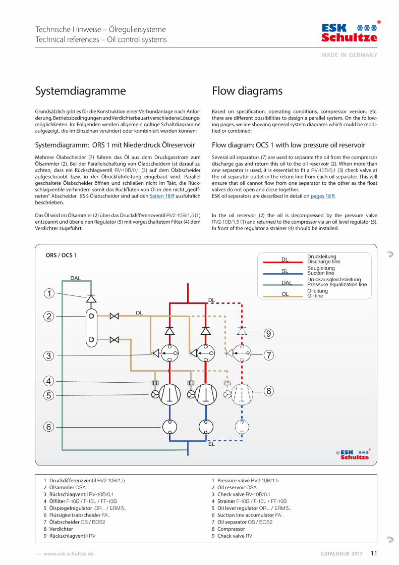
1 Druckdifferenzventil RV2-10B/1,52 Ölsammler OSA3 Rückschlagventil RV-10B/0,14 Ölfilter F-10B / F-10L / FF-10B5 Ölspiegelregulator OR .. / ERM 5.. 6 Flüssigkeitsabscheider FA..7 Ölabscheider OS / BOS28 Verdichter9 Rückschlagventil RV
1 Pressure valve RV2-10B/1.52 Oil reservoir OSA3 Check valve RV-10B/0.14 Strainer F-10B / F-10L / FF-10B5 Oil level regulator OR .. / ERM 5.. 6 Suction line accumulator FA..7 Oil separator OS / BOS28 Compressor9 Check valve RV
Systemdiagramme
Grundsätzlich gibt es für die Konstruktion einer Verbund an lage nach Anfor-derung, Betriebsbedingun gen und Verdichter bauart verschiedene Lö sungs-möglich keiten. Im Folgenden wer den allgemein gültige Schaltdiagramme aufgezeigt, die im Einzelnen verändert oder kombiniert werden können:
Systemdiagramm: ORS 1 mit Niederdruck Ölreservoir
Mehrere Ölabscheider (7) führen das Öl aus dem Druck gas strom zum Öl sammler (2). Bei der Parallelschaltung von Ölabscheidern ist darauf zu achten, dass ein Rück schlag ven til RV-10B/0,1 (3) auf dem Ölab scheider aufgeschraubt bzw. in der Ölrückführleitung eingebaut wird. Parallel ge schaltete Ölabscheider öffnen und schließen nicht im Takt, die Rück-schlag ventile verhindern somit das Rück flu ten von Öl in den nicht „geöff-neten“ Abscheider. ESK-Ölabscheider sind auf den Seiten 18 ff ausführlich beschrieben.
Das Öl wird im Ölsammler (2) über das Druckdifferenzventil RV2-10B/1,5 (1) entspannt und über einen Regulator (5) mit vor ge schaltetem Filter (4) dem Verdichter zugeführt.
Flow diagrams
Based on specification, operating conditions, compressor version, etc. there are different possibilities to design a parallel system. On the follow-ing pages, we are showing general system diagrams which could be modi-fied or combined:
Flow diagram: OCS 1 with low pressure oil reservoir
Several oil separators (7) are used to separate the oil from the compressor discharge gas and return this oil to the oil reservoir (2). When more than one separator is used, it is essential to fit a RV-10B/0,1 (3) check valve at the oil separator outlet in the return line from each oil separator. This will ensure that oil cannot flow from one separator to the other as the float valves do not open and close together. ESK oil separators are described in detail on pages 18 ff.
In the oil reservoir (2) the oil is decompressed by the pressure valve RV2-10B/1,5 (1) and returned to the compressor via an oil level regulator (5). In front of the regulator a strainer (4) should be installed.
ORS / OCS 1
Technische Hinweise – ÖlreguliersystemeTechnical references – Oil control systems
©
11
MADE IN GERMANY
KATALOG 2017 � www.esk-schultze.de
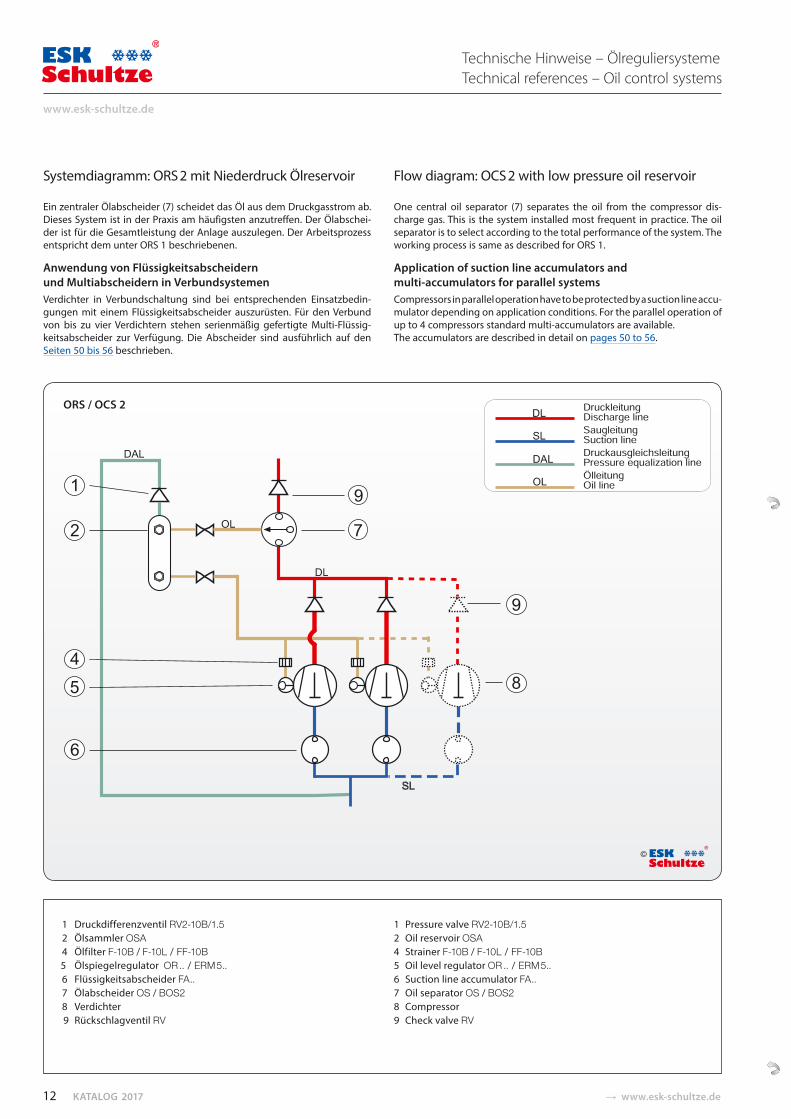
Systemdiagramm: ORS 2 mit Niederdruck Ölreservoir
Ein zentraler Ölabscheider (7) scheidet das Öl aus dem Druck gasstrom ab. Dieses System ist in der Praxis am häufigsten anzutreffen. Der Ölabschei-der ist für die Gesamt leis tung der Anlage auszulegen. Der Arbeitsprozess entspricht dem unter ORS 1 beschriebenen.
Anwendung von Flüssigkeitsabscheidern und Multi abschei dern in VerbundsystemenVerdichter in Verbundschaltung sind bei entsprechenden Ein satz bedin-gungen mit einem Flüssigkeitsabscheider auszurüs ten. Für den Verbund von bis zu vier Verdichtern stehen serien mäßig gefertigte Multi-Flüssig-keitsabscheider zur Ver fügung. Die Abscheider sind ausführlich auf den Seiten 50 bis 56 beschrieben.
Flow diagram: OCS 2 with low pressure oil reservoir
One central oil separator (7) separates the oil from the compressor dis-charge gas. This is the system installed most frequent in practice. The oil separator is to select according to the total performance of the system. The working process is same as described for ORS 1.
Application of suction line accumulators and multi-accumulators for parallel systems Compressors in parallel operation have to be protected by a suction line accu-mulator depending on application conditions. For the parallel operation of up to 4 compressors standard multi-accumulators are available. The accumulators are described in detail on pages 50 to 56.
ORS / OCS 2
1 Druckdifferenzventil RV2-10B/1.52 Ölsammler OSA4 Ölfilter F-10B / F-10L / FF-10B5 Ölspiegelregulator OR .. / ERM 5..6 Flüssigkeitsabscheider FA..7 Ölabscheider OS / BOS28 Verdichter9 Rückschlagventil RV
1 Pressure valve RV2-10B/1.52 Oil reservoir OSA4 Strainer F-10B / F-10L / FF-10B5 Oil level regulator OR .. / ERM 5..6 Suction line accumulator FA..7 Oil separator OS / BOS28 Compressor9 Check valve RV
©
Technische Hinweise – ÖlreguliersystemeTechnical references – Oil control systems
12
www.esk-schultze.de
� www.esk-schultze.de CATALOGUE 2017
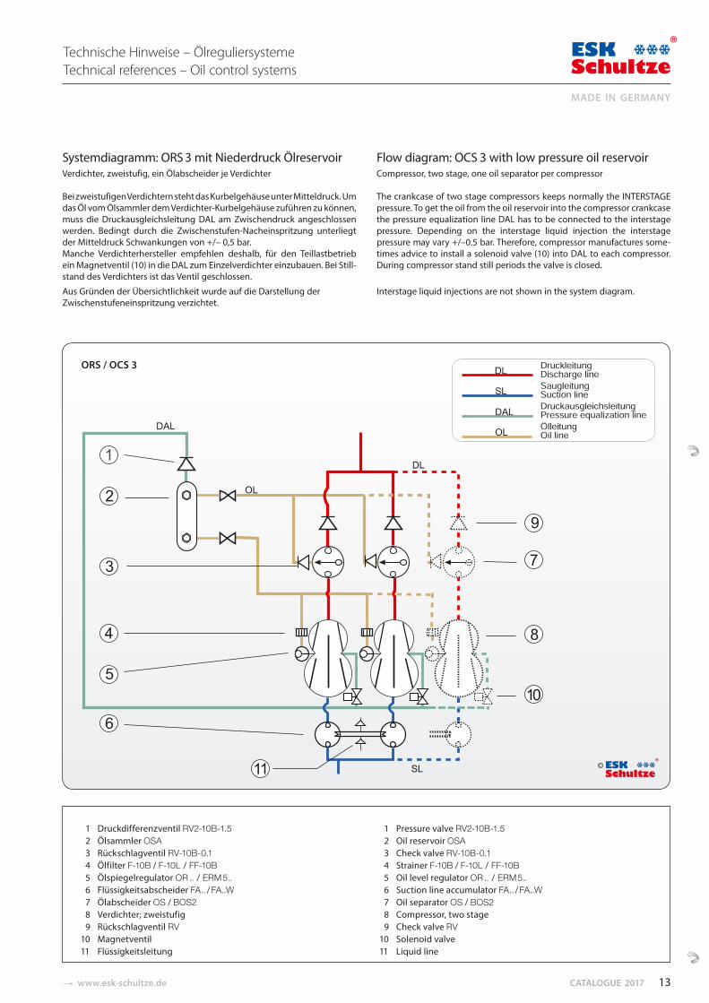
Systemdiagramm: ORS 3 mit Niederdruck ÖlreservoirVerdichter, zweistufig, ein Ölabscheider je Verdichter
Bei zweistufigen Verdichtern steht das Kurbelgehäuse unter Mitteldruck. Um das Öl vom Ölsammler dem Verdichter-Kurbelgehäuse zuführen zu können, muss die Druckaus gleichsleitung DAL am Zwischendruck ange schlossen werden. Bedingt durch die Zwischen stufen-Nacheinspritzung unterliegt der Mitteldruck Schwankungen von +/– 0,5 bar. Manche Verdichterher steller empfehlen deshalb, für den Teillastbetrieb ein Magnetventil (10) in die DAL zum Einzel verdichter einzubauen. Bei Still-stand des Verdichters ist das Ventil geschlossen.
Aus Gründen der Übersichtlichkeit wurde auf die Dar stellung der Zwischenstufeneinspritzung verzichtet.
Flow diagram: OCS 3 with low pressure oil reservoirCompressor, two stage, one oil separator per compressor
The crankcase of two stage compressors keeps normally the INTERSTAGE pressure. To get the oil from the oil reservoir into the compressor crankcase the pressure equalization line DAL has to be connected to the interstage pressure. Depending on the interstage liquid injection the interstage pressure may vary +/–0.5 bar. Therefore, compressor manufactures some- times advice to install a solenoid valve (10) into DAL to each compressor. During compressor stand still periods the valve is closed.
Interstage liquid injections are not shown in the system diagram.
ORS / OCS 3
1 Druckdifferenzventil RV2-10B-1.5 2 Ölsammler OSA 3 Rückschlagventil RV-10B-0.1 4 Ölfilter F-10B / F-10L / FF-10B 5 Ölspiegelregulator OR .. / ERM 5.. 6 Flüssigkeitsabscheider FA.. / FA..W 7 Ölabscheider OS / BOS2 8 Verdichter; zweistufig 9 Rückschlagventil RV10 Magnetventil11 Flüssigkeitsleitung
1 Pressure valve RV2-10B-1.5 2 Oil reservoir OSA 3 Check valve RV-10B-0.1 4 Strainer F-10B / F-10L / FF-10B
5 Oil level regulator OR .. / ERM 5..6 Suction line accumulator FA.. / FA..W
7 Oil separator OS / BOS28 Compressor, two stage
9 Check valve RV10 Solenoid valve11 Liquid line
Technische Hinweise – ÖlreguliersystemeTechnical references – Oil control systems
©
13
MADE IN GERMANY
KATALOG 2017 � www.esk-schultze.de
ORS / OCS 4
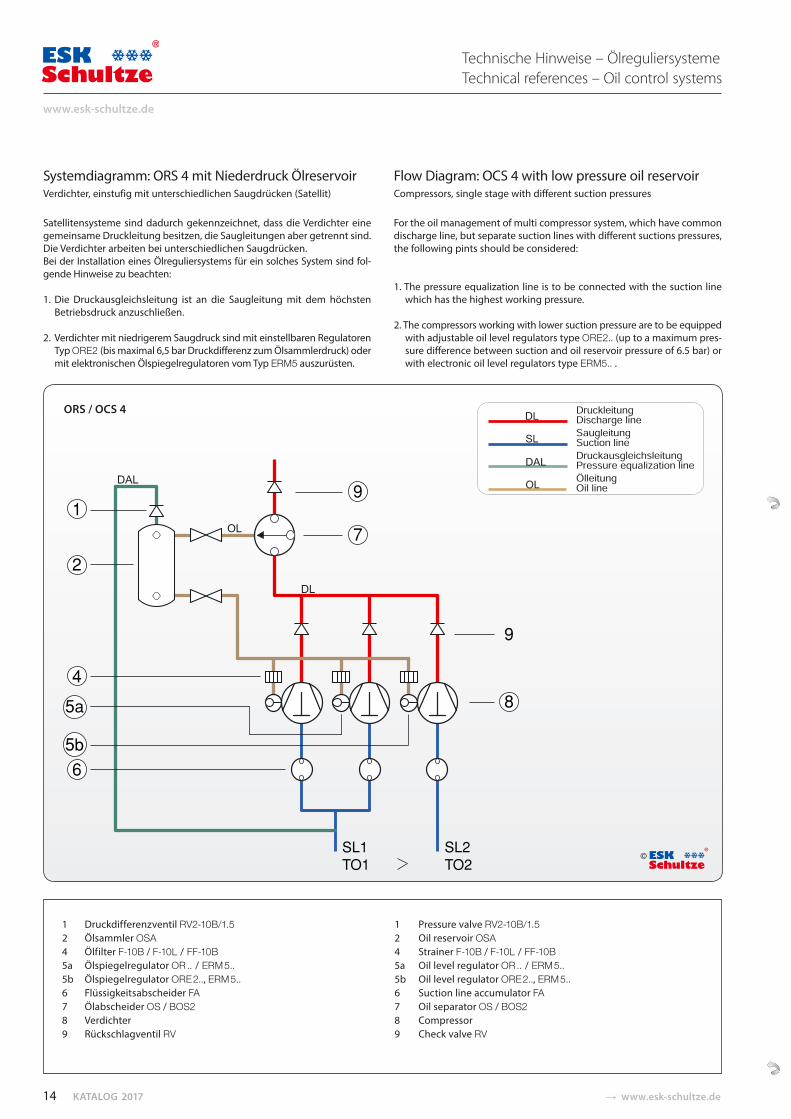
Systemdiagramm: ORS 4 mit Niederdruck ÖlreservoirVerdichter, einstufig mit unterschiedlichen Saugdrücken (Satellit)
Satellitensysteme sind dadurch gekennzeichnet, dass die Verdichter eine gemeinsame Druckleitung besitzen, die Saugleitungen aber getrennt sind. Die Verdichter arbeiten bei unterschiedlichen Saugdrücken. Bei der Installation eines Ölreguliersystems für ein solches System sind fol-gende Hinweise zu beachten:
1. Die Druckausgleichsleitung ist an die Saugleitung mit dem höchstenBetriebsdruck anzuschließen.
2. Verdichter mit niedrigerem Saugdruck sind mit einstellbaren Regulatoren Typ ORE2 (bis maximal 6,5 bar Druckdifferenz zum Ölsammlerdruck) odermit elektronischen Ölspiegelregulatoren vom Typ ERM5 auszurüsten.
Flow Diagram: OCS 4 with low pressure oil reservoirCompressors, single stage with different suction pressures
For the oil management of multi compressor system, which have common discharge line, but separate suction lines with different suctions pressures, the following pints should be considered:
1. The pressure equalization line is to be connected with the suction linewhich has the highest working pressure.
2. The compressors working with lower suction pressure are to be equipped with adjustable oil level regulators type ORE2.. (up to a maximum pres-sure difference between suction and oil reservoir pressure of 6.5 bar) or with electronic oil level regulators type ERM5.. .
1 Druckdifferenzventil RV2-10B/1.5 1 Pressure valve RV2-10B/1.52 Ölsammler OSA 2 Oil reservoir OSA4 Ölfilter F-10B / F-10L / FF-10B 4 Strainer F-10B / F-10L / FF-10B5a Ölspiegelregulator OR .. / ERM 5.. 5a Oil level regulator OR .. / ERM 5..5b Ölspiegelregulator ORE 2.., ERM 5.. 5b Oil level regulator ORE 2.., ERM 5..6 Flüssigkeitsabscheider FA 6 Suction line accumulator FA7 Ölabscheider OS / BOS2 7 Oil separator OS / BOS28 Verdichter 8 Compressor9 Rückschlagventil RV 9 Check valve RV
©
Technische Hinweise – ÖlreguliersystemeTechnical references – Oil control systems
14
www.esk-schultze.de
� www.esk-schultze.de CATALOGUE 2017
ORS / OCS 5
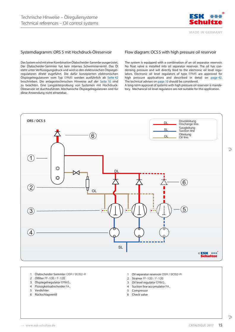
Systemdiagramm: ORS 5 mit Hochdruck-Ölreservoir
Das System wird mit einer Kombination Ölabscheider-Samm ler ausgerüstet. Der Ölabscheider-Sammler hat kein internes Schwim merventil. Das Öl steht unter Verflüssigungs druck und wird so den elektronischen Ölspiegel-regulatoren direkt zugeführt. Die dafür konzipierten elektronischen Ölspiegelregu lato ren vom Typ ERM5 werden ausführlich ab Seite 42 beschrieben. Die anlagentechnischen Hinweise auf der Seite 10 sind zu beachten. Eine Langzeiterprobung von Systemen mit Hoch druck-Ölreservoir ist durchzuführen. Mechanische Öl spie gel regulatoren sind für diese Anwendung nicht einsetzbar.
Flow diagram: OCS 5 with high pressure oil reservoir
The system is equipped with a combination of an oil separator reservoir. No float valve is installed into oil separator reservoir. The oil has con-densing pressure and will directly feed to the electronic oil level regu-lators. Electronic oil level regulators of type ERM5 are approved for high pressure applications and described in detail on page 42. The technical advises on page 10 should be considered. A long-term approval of systems with high pressure oil reservoir is manda-tory. Mechanical oil level regulators are not suitable for this application.
Technische Hinweise – ÖlreguliersystemeTechnical references – Oil control systems
1 Ölabscheider-Sammler OSR / BOS2-R 2 Ölfilter FF-10B / F-10B3 Ölspiegelregulator ERM 5..4 Flüssigkeitsabscheider FA..5 Verdichter6 Rückschlagventil
1 Oil separator reservoir OSR / BOS2-R 2 Strainer FF-10B / F-10B3 Oil level regulator ERM 5..4 Suction line accumulator FA.. 5 Compressor6 Check valve
©
15
MADE IN GERMANY
KATALOG 2017 � www.esk-schultze.de
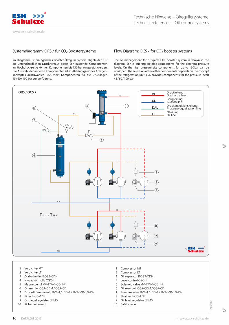
Systemdiagramm: ORS 7 für CO2 Boostersysteme
Im Diagramm ist ein typisches Booster-Ölreguliersystem abgebildet. Für die unterschiedlichen Druckniveaus bietet ESK passende Komponenten an. Hochdruckseitig können Komponenten bis 130 bar eingesetzt werden. Die Auswahl der anderen Komponenten ist in Abhängigkeit des Anlagen-konzeptes auszuwählen. ESK stellt Komponenten für die Drucklagen 45 / 60 / 100 bar zur Verfügung.
Flow Diagram: OCS 7 for CO2 booster systems
The oil management for a typical CO2 booster system is shown in the diagram. ESK is offering suitable components for the different pressure levels. On the high pressure site components for up to 130 bar can be equipped. The selection of the other components depends on the concept of the refrigeration unit. ESK provides components for the pressure levels 45 / 60 / 100 bar.
Technische Hinweise – ÖlreguliersystemeTechnical references – Oil control systems
ORS / OCS 7
1 Verdichter MT 2 Verdichter LT 3 Ölabscheider BOS3-CDH 4 Niveaukontrolle OSC-1 5 Magnetventil MV-11W-1-CDH-P 6 Ölsammler OSA-CDM / OSA-CD 7 Druckdifferenzventil RV3-4,5-CDM / RV2-10B-1,5-2W 8 Filter F-CDM / F.. 9 Ölspiegelregulator ERM 5 10 Sicherheitsventil
1 Compressor MT 2 Compressor LT 3 Oil separator BOS3-CDH 4 Level control OSC-1 5 Solenoid valve MV-11W-1-CDH-P 6 Oil reservoir OSA-CDM / OSA-CD 7 Pressure valve RV3-4.5-CDM / RV2-10B-1.5-2W 8 Strainer F-CDM / F..
9 Oil level regulator ERM 5 10 Safety valve
©
2016
0906
16
www.esk-schultze.de
� www.esk-schultze.de CATALOGUE 2017
Technische Hinweise – ÖlreguliersystemeTechnical references – Oil control systems
17
MADE IN GERMANY
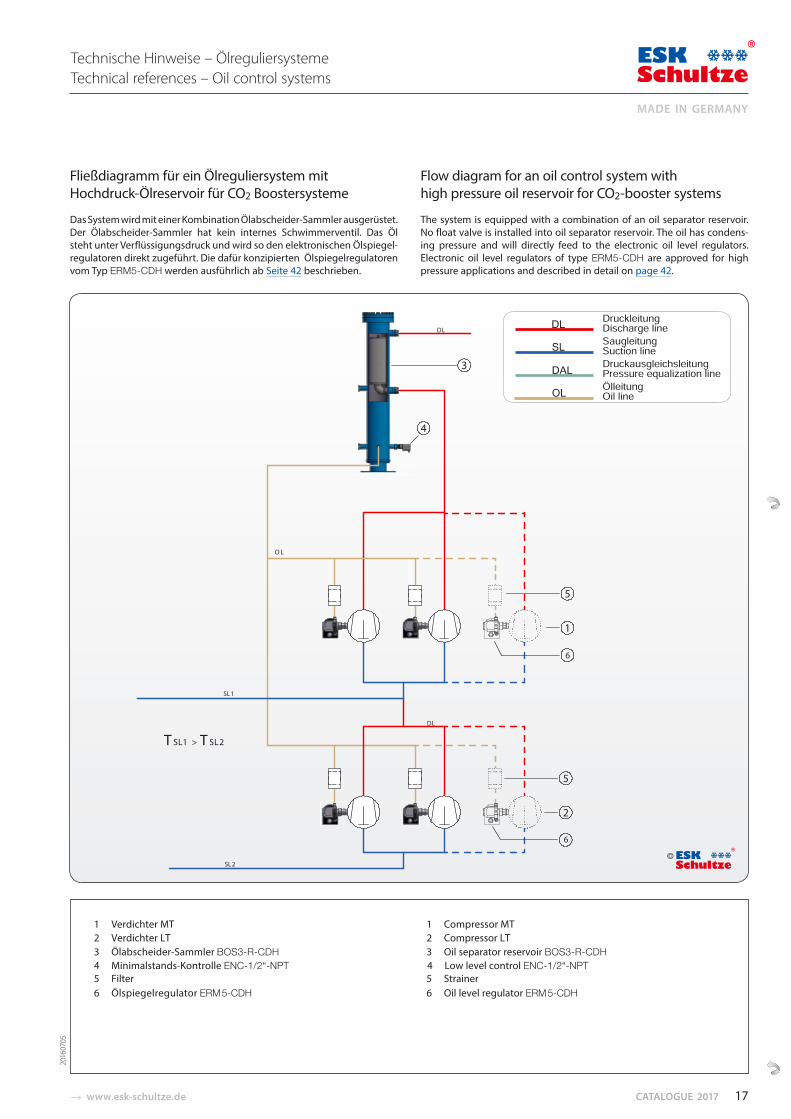
Fließdiagramm für ein Ölreguliersystem mit Hochdruck-Ölreservoir für CO2 Boostersysteme
Das System wird mit einer Kombination Ölabscheider-Samm ler ausgerüstet. Der Ölabscheider-Sammler hat kein internes Schwim merventil. Das Öl steht unter Verflüssigungs druck und wird so den elektronischen Ölspiegel-regulatoren direkt zugeführt. Die dafür konzipierten Ölspiegelregu lato ren vom Typ ERM5-CDH werden ausführlich ab Seite 42 beschrieben.
Flow diagram for an oil control system with high pressure oil reservoir for CO2-booster systems
The system is equipped with a combination of an oil separator reservoir. No float valve is installed into oil separator reservoir. The oil has condens-ing pressure and will directly feed to the electronic oil level regulators. Electronic oil level regulators of type ERM5-CDH are approved for high pressure applications and described in detail on page 42.
1 Verdichter MT 2 Verdichter LT 3 Ölabscheider-Sammler BOS3-R-CDH 4 Minimalstands-Kontrolle ENC-1/2“-NPT 5 Filter 6 Ölspiegelregulator ERM 5-CDH
1 Compressor MT 2 Compressor LT 3 Oil separator reservoir BOS3-R-CDH 4 Low level control ENC-1/2“-NPT 5 Strainer 6 Oil level regulator ERM 5-CDH
©
DL
SL1
DL
SL2
T SL1 > T SL2
1
6
5
4
3
6
2
5
2016
0705
KATALOG 2017 � www.esk-schultze.de
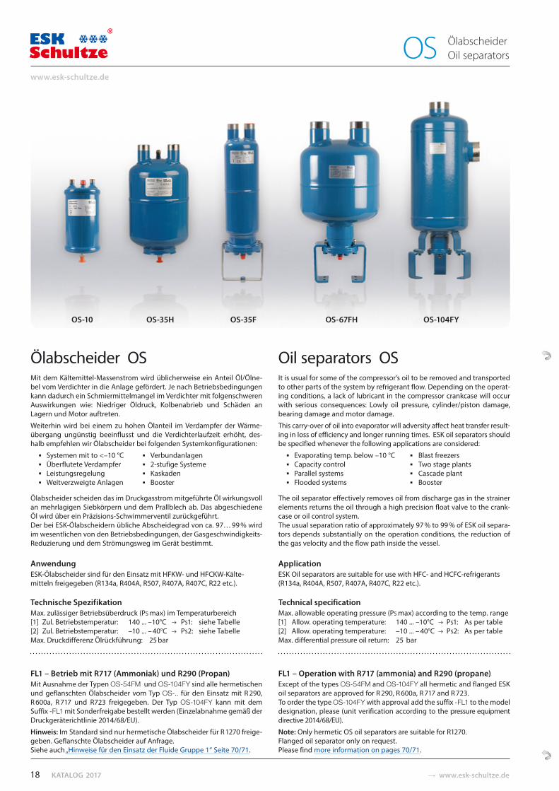
Ölabscheider OS Mit dem Kältemittel-Massenstrom wird üblicherweise ein Anteil Öl/Ölne-bel vom Verdichter in die Anlage gefördert. Je nach Betriebsbedingungen kann dadurch ein Schmiermittelmangel im Verdichter mit folgenschweren Auswirkungen wie: Niedriger Öldruck, Kolbenabrieb und Schäden an Lagern und Motor auftreten.
Weiterhin wird bei einem zu hohen Ölanteil im Verdampfer der Wärme-übergang ungünstig beeinflusst und die Verdichterlaufzeit erhöht, des-halb empfehlen wir Ölabscheider bei folgenden Systemkonfigurationen:
Systemen mit to <–10 °C Verbundanlagen Überflutete Verdampfer 2-stufige Systeme Leistungsregelung KaskadenWeitverzweigte Anlagen Booster
Ölabscheider scheiden das im Druckgasstrom mitgeführte Öl wirkungsvoll an mehrlagigen Siebkörpern und dem Prall blech ab. Das abgeschiedene Öl wird über ein Präzisions-Schwimmerventil zurückgeführt. Der bei ESK- Ölabscheidern übliche Abscheidegrad von ca. 97… 99 % wird im wesentlichen von den Betriebsbedingungen, der Gasgeschwindigkeits-Reduzierung und dem Strömungsweg im Gerät bestimmt.
AnwendungESK-Ölabscheider sind für den Einsatz mit HFKW- und HFCKW-Kälte-mitteln freigegeben (R134a, R404A, R507, R407A, R407C, R22 etc.).
Technische Spezifikation Max. zulässiger Betriebsüberdruck (PS max) im Temperaturbereich[1] Zul. Betriebstemperatur: 140 ... –10°C PS1: siehe Tabelle[2] Zul. Betriebstemperatur: –10 ... – 40°C PS2: siehe TabelleMax. Druckdifferenz Ölrückführung: 25 bar
FL1 – Betrieb mit R717 (Ammoniak) und R290 (Propan)Mit Ausnahme der Typen OS-54FM und OS-104FY sind alle hermetischen und geflanschten Ölabscheider vom Typ OS-.. für den Einsatz mit R 290, R 600a, R 717 und R723 freigegeben. Der Typ OS-104FY kann mit dem Suffix -FL1 mit Sonderfreigabe bestellt werden (Einzelabnahme gemäß der Druckgeräterichtlinie 2014/68/EU).
Hinweis: Im Standard sind nur hermetische Ölabscheider für R 1270 freige-geben. Geflanschte Ölabscheider auf Anfrage. Siehe auch „Hinweise für den Einsatz der Fluide Gruppe 1“ Seite 70/71.
Oil separators OS It is usual for some of the compressor’s oil to be removed and transported to other parts of the system by refrigerant flow. Depending on the operat-ing conditions, a lack of lubricant in the compressor crankcase will occur with serious consequences: Lowly oil pressure, cylinder/piston damage, bearing damage and motor damage.
This carry-over of oil into evaporator will adversity affect heat transfer result-ing in loss of efficiency and longer running times. ESK oil separators should be specified whenever the following applications are considered:
Evaporating temp. below –10 °C Blast freezers Capacity control Two stage plants Parallel systems Cascade plant Flooded systems Booster
The oil separator effectively removes oil from discharge gas in the strainer elements returns the oil through a high precision float valve to the crank-case or oil control system. The usual separation ratio of approximately 97 % to 99 % of ESK oil separa-tors depends substantially on the operation conditions, the reduction of the gas velocity and the flow path inside the vessel.
ApplicationESK Oil separators are suitable for use with HFC- and HCFC-refrigerants (R134a, R404A, R507, R407A, R407C, R22 etc.).
Technical specificationMax. allowable operating pressure (PS max) according to the temp. range [1] Allow. operating temperature: 140 ... –10°C PS1: As per table[2] Allow. operating temperature: –10 ... – 40°C PS2: As per tableMax. differential pressure oil return: 25 bar
FL1 – Operation with R717 (ammonia) and R290 (propane) Except of the types OS-54FM and OS-104FY all hermetic and flanged ESK oil separators are approved for R 290, R 600a, R 717 and R 723. To order the type OS-104FY with approval add the suffix -FL1 to the model designation, please (unit verification according to the pressure equipment directive 2014/68/EU).
Note: Only hermetic OS oil separators are suitable for R1270. Flanged oil separator only on request. Please find more information on pages 70/71.
OS-10 OS-35H OS-35F OS-67FH OS-104FY
Ölabscheider Oil separators OS
18
www.esk-schultze.de
� www.esk-schultze.de CATALOGUE 2017
Auswahlgrundsätze1. Die Anschlussgröße Ø DL des Ölabscheiders darf niemals kleiner
gewählt werden als der Druckleitungsdurchmesser, der entsprechendkältetechnischer Regeln dimensioniert wurde.
2. Die in der Tabelle den Ölabscheidern zugeordneten max. zul. theo-retischen Fördervolumina der Verdichter dürfen nicht überschrittenwerden (VH max. theo.).
3. Bei zweistufigen Verdichtern ist die Auswahl entsprechend der Volumen-Angabe bei Verdampfungstemperatur –10 °C (Tabelle) vorzunehmen:
VH = (VH ND + VH HD) / 2.
4. Abweichende Auslegungen sind aufgrund versuchstechnischerErprobung zulässig.
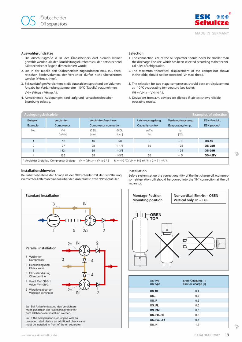
InstallationshinweiseBei Inbetriebnahme der Anlage ist der Ölabscheider mit der Erstölfüllung (Verdichter-Kältemaschinenöl) über den Anschlussstutzen ”IN” vorzufüllen.
Selection1. The connection size of the oil separator should never be smaller than
the discharge line size, which has been selected according to the techni-cal rules of refrig eration.
2. The maximum theoretical displacement of the compressor shownin the table, should not be exceeded (VH max. theo.).
3. The selection for two stage compressors should base on displacementat –10 °C evaporating temperature (see table):
VH = (VH LP + VH HP) / 2.
4. Deviations from a.m. advices are allowed if lab test shows reliableoperating results.
InstallationBefore system set up the correct quantity of the first charge oil, (compres-sor refrigeration oil) should be poured into the ”IN” connection at the oil separator.
1 Verdichter Compressor
2 Rückschlagventil Check valve
3 Ölrückführleitung Oil return line
4 Ventil RV-10B/0.1 Valve RV-10B/0.1
5 Vibrationsabsorber Vibration eliminator
2a Bei Anlaufentlastung des Verdichters muss zusätzlich ein Rückschlagventil vor dem Ölabscheider installiert werden.
2a If the compressor is equipped with an unloaded start device an additional check valve must be installed in front of the oil separator.
Montage-Position Nur vertikal, Eintritt – OBENMounting position Vertical only, In – TOP
Beispiel Verdichter Verdichter-Anschluss Leistungsregelung Verdampfungstemp. ESK-Produkt
Example Compressor Compressor connection Capacity control Evaporating temp. ESK product
No. VH Ø DL Ø DL auf/to t0[m³ / h] [mm] [inch] [%] [°C]
1 12 16 5/8 – – 8 OS-16
2 77 28 1–1/8 50 – 25 OS-28H
3 142* 35 1–3/8 – – 35 OS-35H
4 126 35 1–3/8 30 + 5 OS-42FY
* Verdichter 2-stufig / Compressor 2 stage VH = (VH LP + VH HP) / 2 t0 = –10 °C / VH = 142 m³ / h / 2 = 71 m³ / h
Auslegungsbeispiele Examples of selection
OS-Typ Erste Ölfüllung [ l ]OS type First oil charge [ l ]
OS 10 0,4OS.. 0,6OS..F 0,6OS..FL 0,6OS..FM 0,6OS..FH..FS 0,6OS..FX, ..FY 0,6OS..H 1,2
Standard installation
Parallel installation
Ölabscheider Oil separators OS
19
MADE IN GERMANY
KATALOG 2017 � www.esk-schultze.de
Ölabscheider Lötanschluss Inhalt VH (m³/h) max. zul. Verdichter Hubvolumen, Abmessungen Gewicht PS1 PS2 FL1innen theo. bei 40 °C Verflüssigungstemperatur Standard
Oil separator Solder conn. Volume VH (m³/h) max. allow. comp.displacement, Dimensions Weight PS1 PS2 FL1 ODS theo. at 40 °C condensing temperature standard
Abb. / Typ Ø DL Ø DL Verdampfungstemp. / Evaporating temp. °C Ø D H A Fig. / Type mm inch l 10 0 –10 –20 –30 mm mm mm kg bar bar
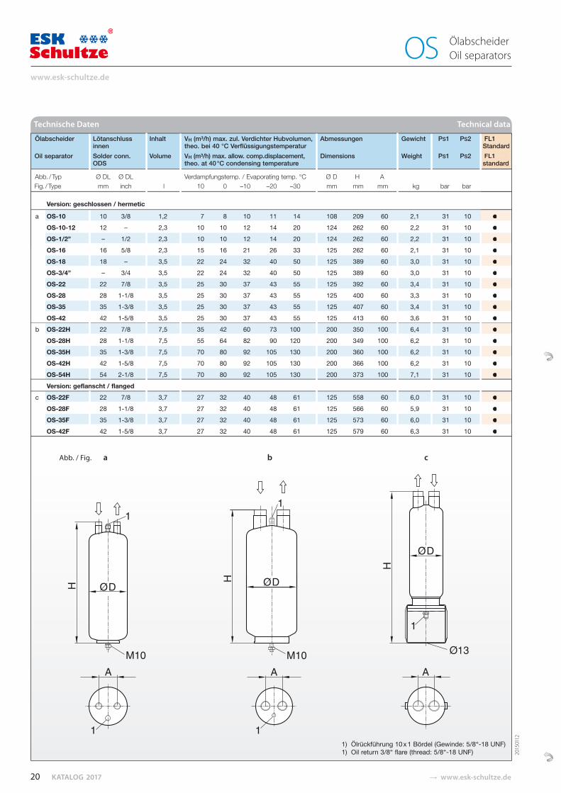
Version: geschlossen / hermetic
a OS-10 10 3/8 1,2 7 8 10 11 14 108 209 60 2,1 31 10 ● OS-10-12 12 – 2,3 10 10 12 14 20 124 262 60 2,2 31 10 ● OS-1/2” – 1/2 2,3 10 10 12 14 20 124 262 60 2,2 31 10 ● OS-16 16 5/8 2,3 15 16 21 26 33 125 262 60 2,1 31 10 ● OS-18 18 – 3,5 22 24 32 40 50 125 389 60 3,0 31 10 ● OS-3/4” – 3/4 3,5 22 24 32 40 50 125 389 60 3,0 31 10 ● OS-22 22 7/8 3,5 25 30 37 43 55 125 392 60 3,4 31 10 ● OS-28 28 1-1/8 3,5 25 30 37 43 55 125 400 60 3,3 31 10 ● OS-35 35 1-3/8 3,5 25 30 37 43 55 125 407 60 3,4 31 10 ● OS-42 42 1-5/8 3,5 25 30 37 43 55 125 413 60 3,6 31 10 ●
b OS-22H 22 7/8 7,5 35 42 60 73 100 200 350 100 6,4 31 10 ● OS-28H 28 1-1/8 7,5 55 64 82 90 120 200 349 100 6,2 31 10 ● OS-35H 35 1-3/8 7,5 70 80 92 105 130 200 360 100 6,2 31 10 ● OS-42H 42 1-5/8 7,5 70 80 92 105 130 200 366 100 6,2 31 10 ● OS-54H 54 2-1/8 7,5 70 80 92 105 130 200 373 100 7,1 31 10 ● Version: geflanscht / flanged
c OS-22F 22 7/8 3,7 27 32 40 48 61 125 558 60 6,0 31 10 ● OS-28F 28 1-1/8 3,7 27 32 40 48 61 125 566 60 5,9 31 10 ● OS-35F 35 1-3/8 3,7 27 32 40 48 61 125 573 60 6,0 31 10 ●
OS-42F 42 1-5/8 3,7 27 32 40 48 61 125 579 60 6,3 31 10 ●
Technische Daten Technical data
●●
● ● ● ● ● ● ● ● ● ● ● ●
FL1StandardFL1standard
●
● ● ● ●
Ölabscheider Oil separators OS
Abb. / Fig. a b c
1) Ölrückführung 10 x 1 Bördel (Gewinde: 5/8“-18 UNF)1) Oil return 3/8“ flare (thread: 5/8“-18 UNF) 20
1501
12
20
www.esk-schultze.de
� www.esk-schultze.de CATALOGUE 2017
Ölabscheider Lötanschluss Inhalt VH (m³/h) max. zul. Verdichter Hubvolumen, Abmessungen Gewicht PS1 PS2 FL1innen theo. bei 40 °C Verflüssigungstemperatur Standard
Oil separator Solder conn. Volume VH (m³/h) max. allow. comp. displacement, Dimensions Weight PS1 PS2 FL1ODS theo. at 40 °C condensing temperature standard
Abb. / Typ Ø DL Ø DL Verdampfungstemp. / Evaporating temp. °C Ø D H A Fig. / Type mm inch l 10 0 –10 –20 –30 mm mm mm kg bar bar
Version: geflanscht / flanged
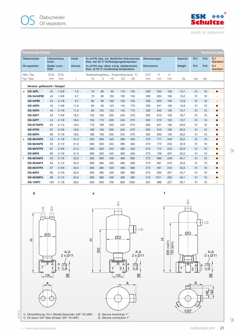
d OS-42FL 42 1-5/8 7,5 70 80 95 116 150 200 520 100 10,7 31 10 ●OS-54/42FM 42 1-5/8 9,7 75 85 100 120 155 200 653 100 13,2 31 10 –OS-54FM 54 2-1/8 9,7 80 90 100 120 155 200 623 100 12,8 31 10 – OS-42FH 42 1-5/8 11,0 85 95 123 145 175 200 641 100 13,9 31 10 ●OS-54FH 54 2-1/8 11,0 90 102 123 145 175 200 642 100 13,7 31 10 ●
OS-42FY 42 1-5/8 18,5 150 160 205 245 270 302 610 150 16,7 31 10 ●OS-54FY 54 2-1/8 18,5 160 170 205 245 270 302 610 150 19,7 31 10 ●
OS-67/64FH 64 2-1/2 18,5 170 180 205 245 270 302 641 150 20,6 31 10 ●OS-67FH 67 2-5/8 18,5 180 190 205 245 270 302 610 150 20,0 31 10 ●
OS-80FH 80 3-1/8 18,5 180 190 205 245 270 302 620 150 20,0 31 10 ● e OS-80/54FS 54 2-1/8 21,0 230 280 345 390 450 273 777 248 33,0 31 10 ●
OS-80/64FS 64 2-1/2 21,0 280 300 345 390 450 273 772 243 32,9 31 10 ●OS-80/67FS 67 2-5/8 21,0 280 300 345 390 450 273 772 243 32,9 31 10 ●
OS-80FS 80 3-1/8 21,0 280 300 345 390 450 273 736 207 32,0 31 10 ● f OS-80/54FX 54 2-1/8 32,0 360 380 430 480 580 273 996 248 45,7 31 10 ●
OS-80/64FX 64 2-1/2 32,0 360 380 430 480 580 273 991 243 45,6 31 10 ●OS-80/67FX 67 2-5/8 32,0 360 380 430 480 580 273 991 243 45,6 31 10 ●
OS-80FX 80 3-1/8 32,0 360 380 430 480 580 273 955 207 44,7 31 10 ●OS-80/89FX 89 3-1/2 32,0 360 380 430 480 580 273 1011 263 46,1 31 10 ●
OS-104FY 104 4-1/8 46,5 500 600 700 800 1000 324 966 227 59,1 31 10 ○
Technische Daten Technical data
●
– – ●
●
●
●
●
●
●
●
●
●
●
●
●
●
●
●
○
FL1Standard FL1standard
Ölabscheider Oil separators OS
d e f
1) Ölrückführung 10 x 1 Bördel (Gewinde: 5/8“-18 UNF) 2) Service Anschluss 1”1) Oil return 3/8“ flare (thread: 5/8“-18 UNF) 2) Service connection 1”20
1501
12
21
MADE IN GERMANY
KATALOG 2017 � www.esk-schultze.de
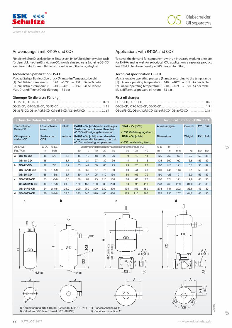
Anwendungen mit R410A und CO2
Für die erhöhte Drucklage beim Einsatz von R410A beziehungsweise auch für den subkritischen Einsatz von CO2 wurde eine separate Baureihe OS-CD spezifiziert, die für max. Betriebsdrücke bis zu 53 bar ausgelegt ist.
Technische Spezifikation OS-CD Max. zulässiger Betriebsüberdruck (PS max) im Temperaturbereich[1] Zul. Betriebstemperatur: 140 ... –10°C PS1: Siehe Tabelle [2] Zul. Betriebstemperatur: –10 ... – 40°C PS2: Siehe TabelleMax. Druckdifferenz Ölrückführung: 35 bar
Ölmenge für die erste Füllung: OS-16-CD, OS-18-CD …………………………………………………………………… 0,6 lOS-22-CD, OS-35/28-CD, OS-35-CD ……………………………………………… 1,5 lOS-35FS-CD, OS-54/42FS-CD, OS-54FS-CD, OS-80FX-CD ………………0,75 l
Applications with R410A and CO2
To cover the demand for components with an increased working pressure for R 410A and as well for subcritical CO2 applications a separate product line OS-CD has been developed (PS max up to 53 bar).
Technical specification OS-CD Max. allowable operating pressure (PS max) according to the temp. range [1] Allow. operating temperature: 140 ... –10°C PS1: As per table[2] Allow. operating temperature: –10 ... – 40°C PS2: As per tableMax. differential pressure oil return 35 bar
First oil charge:OS-16-CD, OS-18-CD …………………………………………………………………… 0.6 lOS-22-CD, OS-35/28-CD, OS-35-CD ……………………………………………… 1.5 lOS-35FS-CD, OS-54/42FS-CD, OS-54FS-CD, OS-80FX-CD ………………0.75 l
480
(54F
S-CD)
509
(35F
S-CD)
Ölabscheider Lötanschluss Inhalt R410A – VH [m³/h] max. zulässiges R744 – VH [m³/h] Abmessungen Gewicht PS1 PS2 Serie -CD innen Verdichterhubvolumen, theo. bei:
40 °C Verflüssigungstemperatur –10°C Verflüssigungstemp. Oil separator Solder conn. Volume R410A – VH [m³/h] max. allowable R744 – VH [m³/h] Dimensions Weight PS1 PS2 series -CD ODS compressor displacement, theo. at:
40 °C condensing temperature –10°C condensing temp. Abb./Typ Ø DL Ø DL Verdampfungstemperatur / Evaporating temperature [°C] Ø D H A Fig./Type mm inch l 10 0 –10 –20 –30 – 30 – 35 – 40 mm mm mm kg bar bar
a OS-16-CD 16 5/8 2,3 15 16 18 20 26 9 10 11 125 269 60 2,7 53 39 OS-18-CD 18 – 3,7 22 24 27 30 36 14 15 16 125 390 60 3,5 53 39 b OS-22-CD 22 7/8 5,7 35 42 50 60 75 23 25 28 160 418 121 6,1 53 39
OS-35/28-CD 28 1-1/8 5,7 55 60 67 75 90 40 44 48 160 445 143 6,1 53 39 OS-35-CD 35 1-3/8 5,7 80 87 95 110 130 60 65 70 160 423 121 6,0 53 39
c OS-35FS-CD 35 1-3/8 6,0 80 87 95 110 130 60 65 70 160 624 121 12,9 45 30 OS-54/42FS-CD 42 1-5/8 21,0 120 150 180 200 220 80 95 110 273 768 229 34,0 45 30 OS-54FS-CD 54 2-1/8 21,0 200 250 300 330 370 135 155 180 273 741 202 33,6 45 30
d OS-80FX-CD 80 3-1/8 32,0 325 340 370 400 450 185 215 260 273 955 207 44,7 45 30
Technische Daten für R410A / CO2 Technical data for R410A / CO2
a b c d
1) Ölrückführung 10 x 1 Bördel (Gewinde: 5/8“-18 UNF) 2) Service Anschluss 1”1) Oil return 3/8“ flare (Thread: 5/8“-18 UNF) 2) Service connection 1”
9 10 11 14 15 16
23 25 28 40 44 48 60 65 70 60 65 70 80 95 110 135 155 180 185 215 260
ating temperature [°C] – 30 – 35 – 40
R744 – VH [m³/h]
–10°C Verflüssigungstemp. R744 – VH [m³/h]
–10°C condensing temp.
Ölabscheider Oil separators OS
2015
1112
22
www.esk-schultze.de
� www.esk-schultze.de CATALOGUE 2017
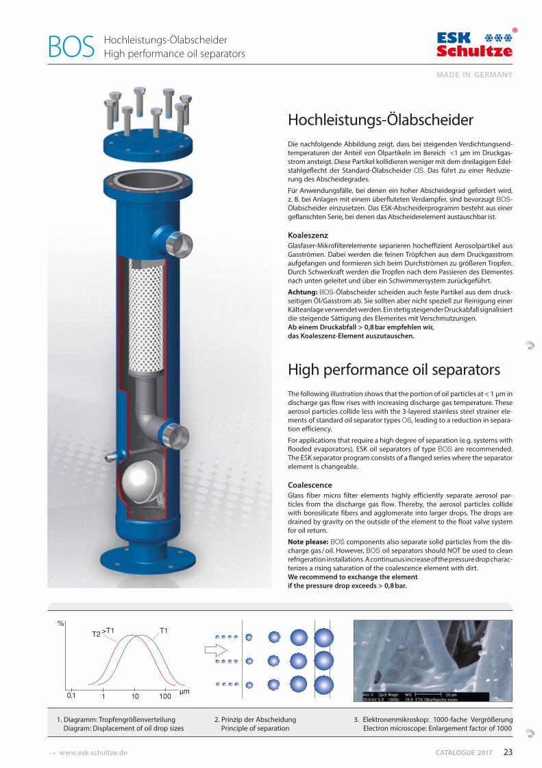
Hochleistungs-ÖlabscheiderDie nachfolgende Abbildung zeigt, dass bei steigenden Verdichtungs end-tem peraturen der Anteil von Ölpartikeln im Bereich <1 μm im Druckgas-strom ansteigt. Diese Partikel kollidieren weniger mit dem dreilagigen Edel-stahl geflecht der Stan dard-Ölabscheider OS. Das führt zu einer Reduzie-rung des Abscheidegrades.
Für Anwendungsfälle, bei denen ein hoher Abscheidegrad gefordert wird, z. B. bei Anlagen mit einem überfluteten Verdampfer, sind bevorzugt BOS-Ölabscheider einzusetzen. Das ESK-Abscheiderprogramm besteht aus einergeflanschten Serie, bei denen das Abscheiderelement austauschbar ist.
KoaleszenzGlasfaser-Mikrofilterelemente separieren hocheffizient Aerosolpartikel aus Gasströmen. Dabei werden die feinen Tröpfchen aus dem Druck gas strom aufgefangen und formieren sich beim Durchströmen zu größeren Tropfen. Durch Schwer kraft werden die Tropfen nach dem Pas sieren des Elementes nach unten geleitet und über ein Schwimmersystem zurückgeführt.
Achtung: BOS-Ölabscheider scheiden auch feste Partikel aus dem druck-seitigen Öl/Gasstrom ab. Sie sollten aber nicht speziell zur Reinigung einer Kälte anlage verwendet werden. Ein stetig steigender Druckabfall signalisiert die steigende Sättigung des Elementes mit Verschmutzungen. Ab einem Druckabfall > 0,8 bar empfehlen wir, das Koaleszenz-Element auszutauschen.
High performance oil separatorsThe following illustration shows that the portion of oil particles at < 1 μm in discharge gas flow rises with increasing discharge gas temperature. These aerosol particles collide less with the 3-layered stainless steel strainer ele-ments of standard oil separator types OS, leading to a reduction in separa-tion efficiency.
For applications that require a high degree of separation (e.g. systems with flooded evaporators), ESK oil separators of type BOS are recommended. The ESK separator program consists of a flanged series where the separator element is changeable.
Coalescence Glass fiber micro filter elements highly efficiently separate aerosol par-ticles from the discharge gas flow. Thereby, the aerosol particles collide with borosilicate fibers and agglomerate into larger drops. The drops are drained by gravity on the outside of the element to the float valve system for oil return.
Note please: BOS components also separate solid particles from the dis-charge gas / oil. However, BOS oil separators should NOT be used to clean refrigeration installations. A continuous increase of the pressure drop charac-terizes a rising saturation of the coalescence element with dirt. We recommend to exchange the element if the pressure drop exceeds > 0,8 bar.
1. Diagramm: Tropfengrößenverteilung 2. Prinzip der Abscheidung 3. Elektronenmikroskop: 1000-fache VergrößerungDiagram: Displacement of oil drop sizes Principle of separation Electron microscope: Enlargement factor of 1000
Hochleistungs-Ölabscheider High performance oil separators BOS
23
MADE IN GERMANY
KATALOG 2017 � www.esk-schultze.de
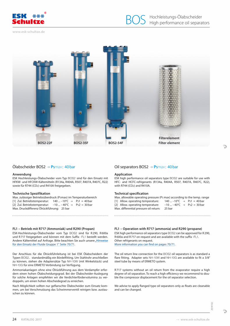
Ölabscheider BOS2 PSmax : 40 bar
AnwendungESK Hochleistungs-Ölabscheider vom Typ BOS2 sind für den Einsatz mit HFKW- und HFCKW-Kälte mitteln (R134a, R404A, R507, R407A, R407C, R22) sowie für R744 (CO2) und R410A freigegeben.
Technische Spezifikation Max. zulässiger Betriebsüberdruck (PSmax) im Temperaturbereich[1] Zul. Betriebstemperatur: 140 ... –10°C PS1 = 40 bar [2] Zul. Betriebstemperatur: –10 ... – 40°C PS2 = 30 barMax. Druckdifferenz Ölrückführung: 25 bar
FL1 – Betrieb mit R717 (Ammoniak) und R290 (Propan)ESK-Hochleistungs-Ölabscheider vom Typ BOS2 sind für R 290, R 600a und R 717 freigegeben und können mit dem Suffix -FL1 bestellt werden. Andere Kältemittel auf Anfrage. Bitte beachten Sie auch unsere „Hinweise für den Einsatz der Fluide Gruppe 1“ Seite 70/71.
Der Anschluss für die Ölrückführleitung ist bei ESK Ölabscheidern der Typen BOS2.. standardmäßig ein Bördelfitting. Um Stahlrohr anschließen zu können, stehen die Adaptersätze Typ NH-10W (mit Winkelstück) und NH-10G für eine ERMETO Verbindung zur Verfügung.
Ammoniakanlagen ohne eine Ölrückführung aus dem Verdampfer erfor-dern einen hohen Ölabscheidungsgrad. Bei der Ölabscheider-Auslegung für solche Anlagen empfehlen wir die Verdichterfördervolumina zu ver-doppeln, um einen hohen Abscheidegrad zu erreichen.
Nach Möglichkeit sollten nur geflanschte Ölabscheider zum Einsatz kom-men, um bei Verschmutzung das Schwimmerventil reinigen bzw. austau-schen zu können.
Oil separators BOS2 PSmax : 40 bar
ApplicationESK high performance oil separators type BOS2 are suitable for use with HFC- and HCFC-refrigerants (R134a, R404A, R507, R407A, R407C, R22), with R744 (CO2) and R410A.
Technical specificationMax. allowable operating pressure (PS max) according to the temp. range [1] Allow. operating temperature: 140 ... –10°C PS1 = 40 bar[2] Allow. operating temperature: –10 ... – 40°C PS2 = 30 barMax. differential pressure oil return: 25 bar
FL1 – Operation with R717 (ammonia) and R290 (propane) ESK high performance oil separators type BOS2 can be approved for R 290, R 600a and R 717 on request and are available with the suffix -FL1. Other refrigerants on request. More information you can find on pages 70/71.
The oil return line connection for the BOS2 oil separators is as standard a flare fitting. Adapter sets NH-10W and NH-10G are available to fit a 3/8” steel tube by means of ERMETO system.
R 717 systems without an oil return from the evaporator require a high degree of oil separation. To reach a high efficiency we recommend to dou-ble the compressor displacement for the oil separator selection.
We advise to apply flanged type oil separators only as floats are cleanable and can be changed.
FilterelementBOS2-22F BOS2-35F BOS2-54F Filter element
Hochleistungs-Ölabscheider High performance oil separators BOS
2014
1102
24
www.esk-schultze.de
� www.esk-schultze.de CATALOGUE 2017
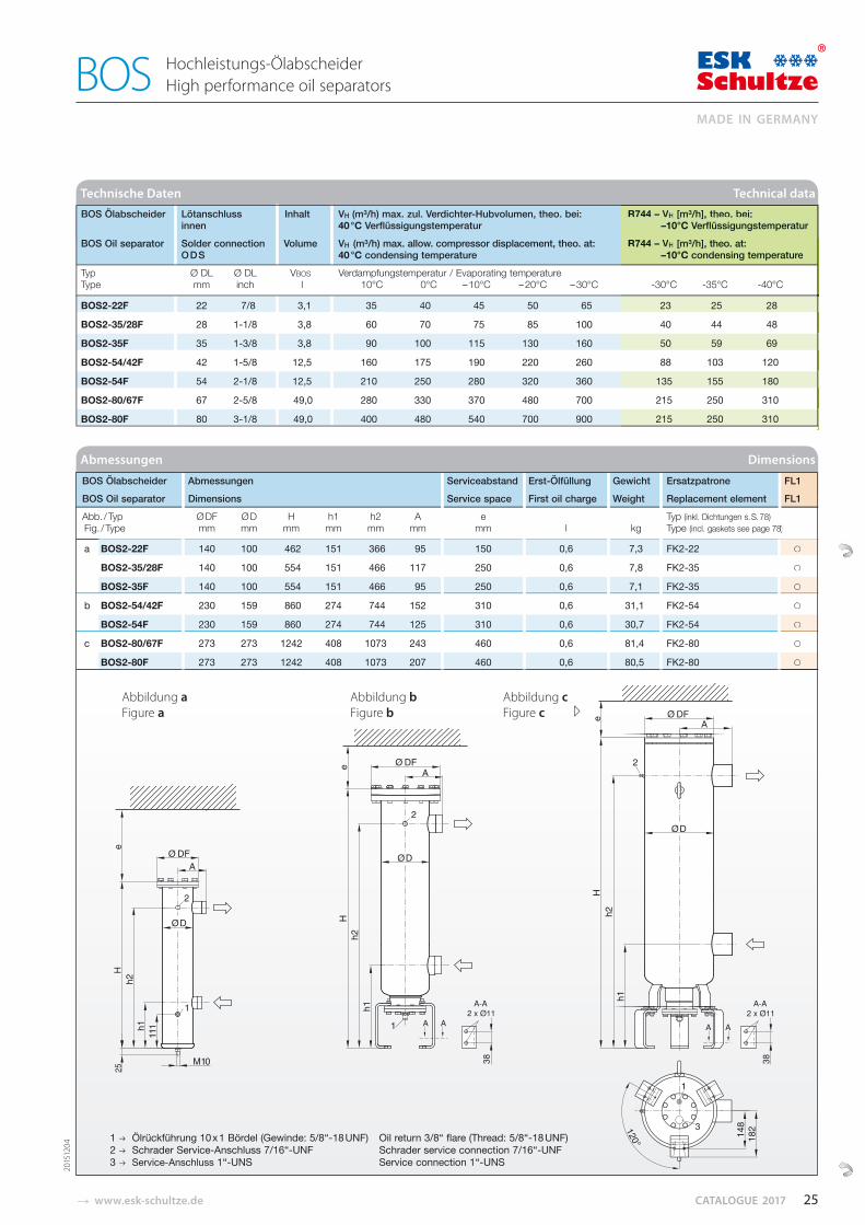
BOS Ölabscheider Lötanschluss Inhalt VH (m³/h) max. zul. Verdichter-Hubvolumen, theo. bei: R744 – VH [m³/h], theo. bei: innen 40 °C Verflüssigungstemperatur –10°C Verflüssigungstemperatur
BOS Oil separator Solder connection Volume VH (m³/h) max. allow. compressor displacement, theo. at: R744 – VH [m³/h], theo. at: O D S 40 °C condensing temperature –10°C condensing temperature
Typ Ø DL Ø DL VBOS Verdampfungstemperatur / Evaporating temperature Type mm inch l 10°C 0°C – 10°C – 20°C – 30°C -30°C -35°C -40°C
BOS 2-22F 22 7/8 3,1 35 40 45 50 65 23 25 28
BOS 2-35/28F 28 1-1/8 3,8 60 70 75 85 100 40 44 48
BOS 2-35F 35 1-3/8 3,8 90 100 115 130 160 50 59 69
BOS 2-54/42F 42 1-5/8 12,5 160 175 190 220 260 88 103 120
BOS 2-54F 54 2-1/8 12,5 210 250 280 320 360 135 155 180
BOS 2-80/67F 67 2-5/8 49,0 280 330 370 480 700 215 250 310
BOS 2-80F 80 3-1/8 49,0 400 480 540 700 900 215 250 310
Technische Daten Technical data
BOS Ölabscheider Abmessungen Serviceabstand Erst-Ölfüllung Gewicht Ersatzpatrone FL1
BOS Oil separator Dimensions Service space First oil charge Weight Replacement element FL1
Abb. / Typ Ø DF Ø D H h1 h2 A e Typ (inkl. Dichtungen s. S. 78) Fig. / Type mm mm mm mm mm mm mm l kg Type (incl. gaskets see page 78)
a BOS 2-22F 140 100 462 151 366 95 150 0,6 7,3 FK 2-22 ○
BOS 2-35/28F 140 100 554 151 466 117 250 0,6 7,8 FK 2-35 ○
BOS 2-35F 140 100 554 151 466 95 250 0,6 7,1 FK 2-35 ○
b BOS 2-54/42F 230 159 860 274 744 152 310 0,6 31,1 FK 2-54 ○
BOS 2-54F 230 159 860 274 744 125 310 0,6 30,7 FK 2-54 ○
c BOS 2-80/67F 273 273 1242 408 1073 243 460 0,6 81,4 FK 2-80 ○
BOS 2-80F 273 273 1242 408 1073 207 460 0,6 80,5 FK 2-80 ○
Abmessungen Dimensions
Abbildung a Abbildung b Abbildung c � Figure a Figure b Figure c
FL1
FL1
8)
○
○
○
○
○
○
○
Hochleistungs-Ölabscheider High performance oil separators BOS
23 25 28
40 44 48
50 59 69
88 103 120
135 155 180
215 250 310
-30°C -35°C -40°C
R744 – VH [m³/h], theo. bei:–10°C Verflüssigungstemperaturr
R744 – VH [m³/h], theo. at: –10°C condensing temperature
215 250 310
2015
1204
25
MADE IN GERMANY
1 Ölrückführung 10 x 1 Bördel (Gewinde: 5/8“-18 UNF) Oil return 3/8“ flare (Thread: 5/8“-18 UNF) 2 Schrader Service-Anschluss 7/16“-UNF Schrader service connection 7/16“-UNF3 Service-Anschluss 1“-UNS Service connection 1“-UNS
KATALOG 2017 � www.esk-schultze.de
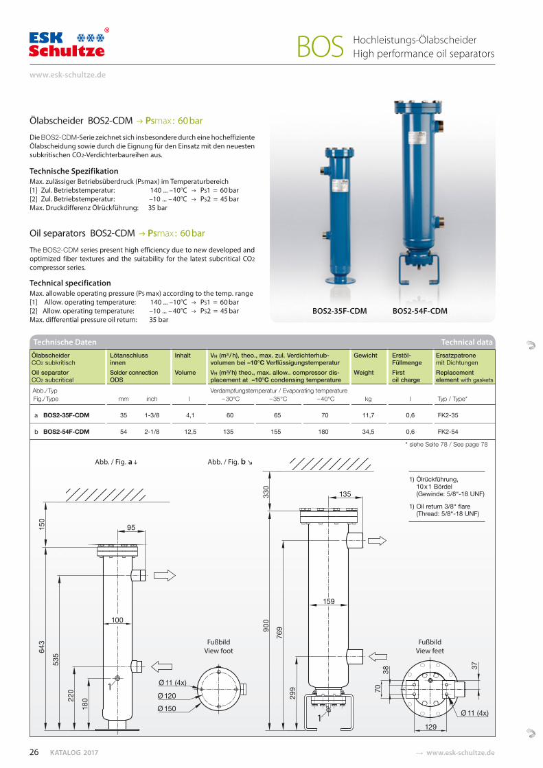
Ölabscheider BOS2-CDM PSmax : 60 bar
Die BOS2-CDM-Serie zeichnet sich insbesondere durch eine hocheffiziente Ölabscheidung sowie durch die Eignung für den Einsatz mit den neuesten subkritischen CO2-Verdichterbaureihen aus.
Technische Spezifikation Max. zulässiger Betriebsüberdruck (PSmax) im Temperaturbereich[1] Zul. Betriebstemperatur: 140 ... –10°C PS1 = 60 bar [2] Zul. Betriebstemperatur: –10 ... – 40°C PS2 = 45 barMax. Druckdifferenz Ölrückführung: 35 bar
Oil separators BOS2-CDM PSmax : 60 bar
The BOS2-CDM series present high efficiency due to new developed and optimized fiber textures and the suitability for the latest subcritical CO2 compressor series.
Technical specification Max. allowable operating pressure (PS max) according to the temp. range [1] Allow. operating temperature: 140 ... –10°C PS1 = 60 bar[2] Allow. operating temperature: –10 ... – 40°C PS2 = 45 barMax. differential pressure oil return: 35 bar
Technische Daten Technical data
Ölabscheider Lötanschluss Inhalt VH (m³ / h), theo., max. zul. Verdichterhub- Gewicht Erstöl- Ersatzpatrone CO2 subkritisch innen volumen bei –10°C Verflüssigungstemperatur Füllmenge mit Dichtungen Oil separator Solder connection Volume VH (m³/ h) theo., max. allow.. compressor dis- Weight First Replacement CO2 subcritical ODS placement at –10°C condensing temperature oil charge element with gaskets
Abb./ Typ Verdampfungstemperatur / Evaporating temperature Fig./ Type mm inch l – 30°C – 35°C – 40°C kg l Typ / Type*
a BOS2-35F-CDM 35 1-3/8 4,1 60 65 70 11,7 0,6 FK2-35
b BOS2-54F-CDM 54 2-1/8 12,5 135 155 180 34,5 0,6 FK2-54
* siehe Seite 78 / See page 78
BOS2-35F-CDM BOS2-54F-CDM
FußbildView foot
FußbildView feet
1) Ölrückführung,10 x 1 Bördel (Gewinde: 5/8“-18 UNF)
1) Oil return 3/8“ flare(Thread: 5/8“-18 UNF)
Abb. / Fig. a Abb. / Fig. b
Hochleistungs-Ölabscheider High performance oil separators BOS
26
www.esk-schultze.de
� www.esk-schultze.de CATALOGUE 2017
Technische Daten Technical data
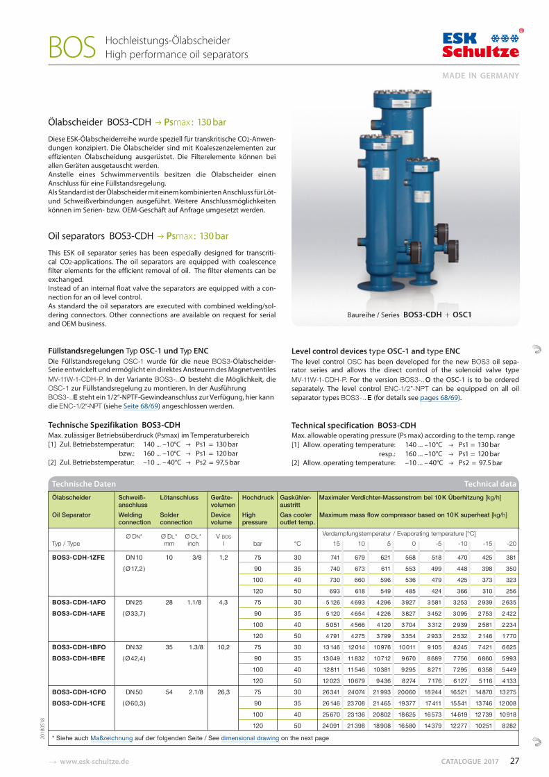
Ölabscheider Schweiß- Lötanschluss Geräte- Hochdruck Gaskühler- Maximaler Verdichter-Massenstrom bei 10 K Überhitzung [kg/h]anschluss volumen austritt
Oil Separator Welding Solder Device High Gas cooler Maximum mass flow compressor based on 10 K superheat [kg/h]connection connection volume pressure outlet temp.
Ø DN* Ø DL * Ø DL * V BOS Verdampfungstemperatur / Evaporating temperature [°C] Typ / Type mm inch l bar °C 15 10 5 0 -5 -10 -15 -20
BOS3-CDH-1ZFE DN 10 10 3/8 1,2 75 30 741 679 621 568 518 470 425 381
( Ø 17,2 ) 90 35 740 673 611 553 499 448 398 350
100 40 730 660 596 536 479 425 373 323
120 50 693 618 549 485 424 366 310 256
BOS3-CDH-1AFO DN 25 28 1.1/8 4,3 75 30 5 126 4 693 4 296 3 927 3 581 3 253 2 939 2 635
BOS3-CDH-1AFE ( Ø 33,7 ) 90 35 5 120 4 654 4 226 3 827 3 452 3 095 2 753 2 422
100 40 5 051 4 566 4 120 3 704 3 312 2 939 2 581 2 234
120 50 4 791 4 275 3 799 3 354 2 933 2 532 2 146 1 770
BOS3-CDH-1BFO DN 32 35 1.3/8 10,2 75 30 13 146 12 014 10 976 10 011 9 105 8 245 7 421 6 625
BOS3-CDH-1BFE ( Ø 42,4 ) 90 35 13 049 11 832 10 712 9 670 8 689 7 756 6 860 5 993
100 40 12 811 11 546 10 381 9 295 8 271 7 295 6 358 5 449
120 50 12 023 10 679 9 436 8 274 7 176 6 127 5 116 4 133
BOS3-CDH-1CFO DN 50 54 2.1/8 26,3 75 30 26 341 24 074 21 993 20 060 18 244 16 521 14 870 13 275
BOS3-CDH-1CFE ( Ø 60,3 ) 90 35 26 146 23 708 21 465 19 377 17 411 15 541 13 746 12 008
100 40 25 670 23 136 20 802 18 625 16 573 14 619 12 739 10 918
120 50 24 091 21 398 18 908 16 580 14 379 12 277 10 251 8 282
* Siehe auch Maßzeichnung auf der folgenden Seite / See dimensional drawing on the next page
Hochleistungs-Ölabscheider High performance oil separators BOS
Ölabscheider BOS3-CDH PSmax : 130 bar
Diese ESK-Ölabscheiderreihe wurde speziell für transkritische CO2-Anwen-dungen konzipiert. Die Ölabscheider sind mit Koales zenz elementen zur effi zienten Ölabscheidung aus gerüstet. Die Filterelemente können bei allen Geräten ausgetauscht werden. Anstelle eines Schwimmerventils besitzen die Ölabscheider einen An schluss für eine Füllstandsregelung. Als Standard ist der Ölabscheider mit einem kombinierten Anschluss für Löt- und Schweißverbindungen ausgeführt. Weitere Anschlussmöglichkeiten können im Serien- bzw. OEM-Geschäft auf Anfrage umgesetzt werden.
Oil separators BOS3-CDH PSmax : 130 bar
This ESK oil separator series has been especially designed for transcriti-cal CO2-applications. The oil separators are equipped with coalescence filter elements for the efficient removal of oil. The filter elements can be exchanged. Instead of an internal float valve the separators are equipped with a con-nection for an oil level control. As standard the oil separators are executed with combined welding/sol-dering connectors. Other connections are available on request for serial and OEM business.
Füllstandsregelungen Typ OSC-1 und Typ ENCDie Füllstandsregelung OSC-1 wurde für die neue BOS3-Ölabscheider-Serie entwickelt und ermöglicht ein direktes Ansteuern des Magnetventiles MV-11W-1-CDH-P. In der Variante BOS3-.. O besteht die Möglichkeit, die OSC-1 zur Füllstandsregelung zu montieren. In der Ausführung BOS3-..E steht ein 1/2“-NPTF-Gewindeanschluss zur Verfügung, hier kann die ENC-1/2“-NPT (siehe Seite 68/69) angeschlossen werden.
Technische Spezifikation BOS3-CDH Max. zulässiger Betriebsüberdruck (PSmax) im Temperaturbereich[1] Zul. Betriebstemperatur: 140 ... –10°C PS1 = 130 bar
bzw.: 160 ... –10°C PS1 = 120 bar [2] Zul. Betriebstemperatur: –10 ... – 40°C PS2 = 97,5 bar
Level control devices type OSC-1 and type ENCThe level control OSC has been developed for the new BOS3 oil sepa-rator series and allows the direct control of the solenoid valve type MV-11W-1-CDH-P. For the version BOS3-.. O the OSC-1 is to be ordered separately. The level control ENC-1/2”-NPT can be equipped on all oil separator types BOS3- .. E (for details see pages 68/69).
Technical specification BOS3-CDHMax. allowable operating pressure (PS max) according to the temp. range [1] Allow. operating temperature: 140 ... –10°C PS1 = 130 bar
resp.: 160 ... –10°C PS1 = 120 bar [2] Allow. operating temperature: –10 ... – 40°C PS2 = 97.5 bar
Baureihe / Series BOS3-CDH + OSC1
20180518
27
MADE IN GERMANY
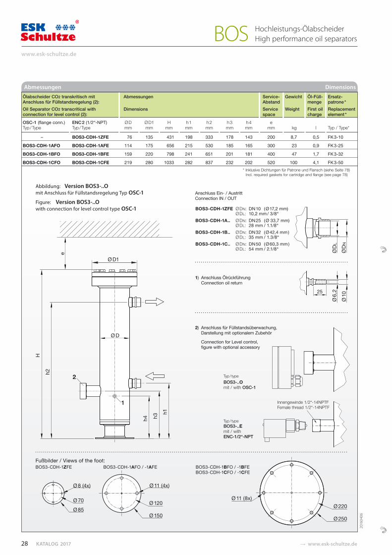
KATALOG 2017 � www.esk-schultze.de
Abmessungen Dimensions
Abbildung: Version BOS3-..O mit Anschluss für Füllstandsregelung Typ OSC-1
Figure: Version BOS3-..O with connection for level control type OSC-1
Hochleistungs-Ölabscheider High performance oil separators BOS
Anschluss Ein- / AustrittConnection IN / OUT
1) Anschluss ÖlrückführungConnection oil return
2) Anschluss für Füllstandsüberwachung,Darstellung mit optionalem Zubehör
Connection for Level control,figure with optional accessory
Typ / type BOS3-..Omit / with OSC-1
Typ / type BOS3-..E mit / with ENC-1/2“-NPT
Fußbilder / Views of the foot: BOS3-CDH-1ZFE BOS3-CDH-1AFO / -1AFE BOS3-CDH-1BFO / -1BFE
BOS3-CDH-1CFO / -1CFE
BOS3-CDH-1ZFE Ø DN: DN 10 ( Ø 17,2 mm)Ø DL: 10,2 mm / 3/8“
BOS3-CDH-1A.. Ø DN: DN 25 ( Ø 33,7 mm)Ø DL: 28 mm / 1.1/8“
BOS3-CDH-1B.. Ø DN: DN 32 ( Ø 42,4 mm ) Ø DL: 35 mm / 1.3/8“
BOS3-CDH-1C.. Ø DN: DN 50 ( Ø 60,3 mm )Ø DL: 54 mm / 2.1/8“1
Innengewinde 1/2“-14NPTFFemale thread 1/2“-14NPTF
2016
0406
Ölabscheider CO2 transkritisch mit Abmessungen Service- Gewicht Öl-Füll- Ersatz- Anschluss für Füllstandsregelung (2): Abstand menge patrone * Oil Separator CO2 transcritical with Dimensions Service Weight First oil Replacement connection for level control (2): space charge element *
OSC-1 (flange conn.) ENC 2 (1/2“-NPT) Ø D Ø D1 H h 1 h 2 h 3 h 4 e Typ / Type Typ / Type mm mm mm mm mm mm mm mm kg l Typ / Type*
– BOS3-CDH-1ZFE 76 135 431 198 333 178 143 200 8,7 0,5 FK 3-10
BOS3-CDH-1AFO BOS3-CDH-1AFE 114 175 656 215 530 185 165 300 23 0,9 FK 3-25
BOS3-CDH-1BFO BOS3-CDH-1BFE 159 220 798 241 651 201 181 400 47 1,7 FK 3-32
BOS3-CDH-1CFO BOS3-CDH-1CFE 219 280 1033 282 837 232 202 520 100 4,1 FK 3-50* Inklusive Dichtungen für Patrone und Flansch (siehe Seite 78)
Incl. required gaskets for cartridge and flange (see page 78)
28
www.esk-schultze.de
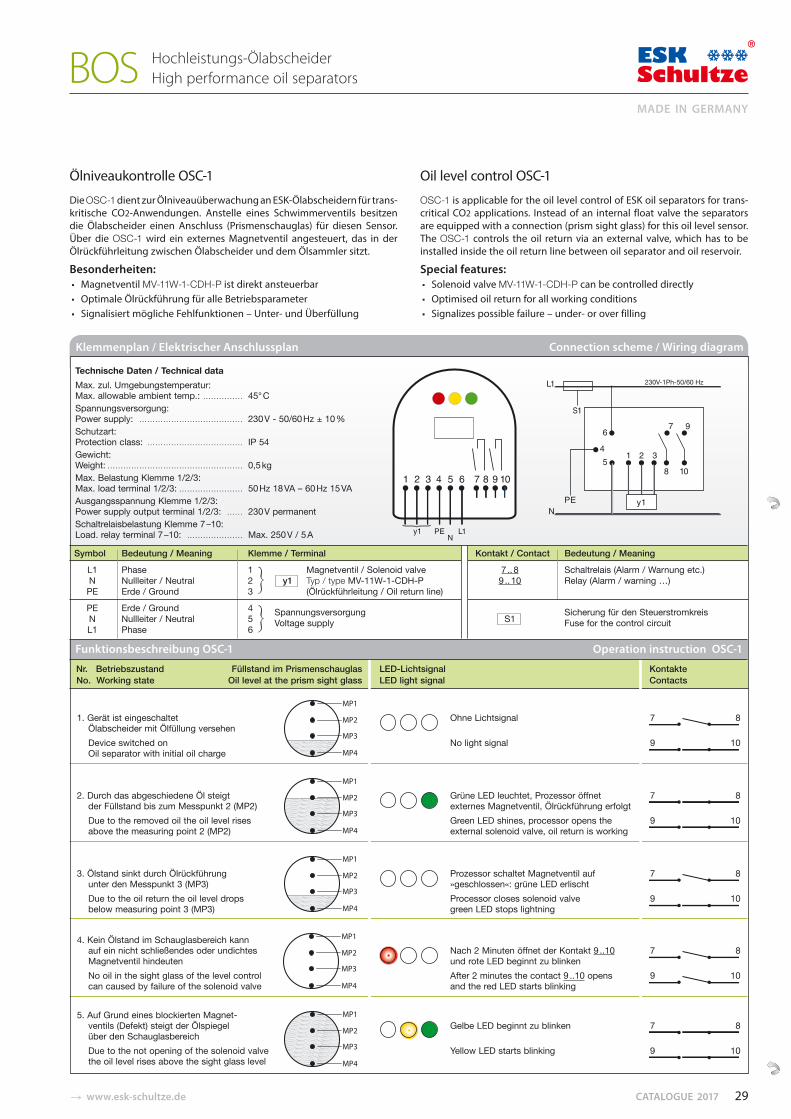
� www.esk-schultze.de CATALOGUE 2017
Ölniveaukontrolle OSC-1
Die OSC-1 dient zur Ölniveauüberwachung an ESK-Ölabscheidern für trans-kritische CO2-Anwendungen. Anstelle eines Schwimmerventils besitzen die Ölabscheider einen Anschluss (Prismenschau glas) für diesen Sensor. Über die OSC-1 wird ein externes Magnetventil angesteuert, das in der Ölrückführleitung zwischen Ölabscheider und dem Ölsammler sitzt.
Besonderheiten:▪ Magnetventil MV-11W-1-CDH-P ist direkt ansteuerbar ▪ Optimale Ölrückführung für alle Betriebsparameter▪ Signalisiert mögliche Fehlfunktionen – Unter- und Überfüllung
Oil level control OSC-1
OSC-1 is applicable for the oil level control of ESK oil separators for trans-critical CO2 applications. Instead of an internal float valve the separators are equipped with a connection (prism sight glass) for this oil level sensor. The OSC-1 controls the oil return via an external valve, which has to be installed inside the oil return line between oil separator and oil reservoir.
Special features:▪ Solenoid valve MV-11W-1-CDH-P can be controlled directly▪ Optimised oil return for all working conditions▪ Signalizes possible failure – under- or over filling
Hochleistungs-Ölabscheider High performance oil separators BOS
1. Gerät ist eingeschaltetÖlabscheider mit Ölfüllung versehenDevice switched onOil separator with initial oil charge
2. Durch das abgeschiedene Öl steigtder Füllstand bis zum Messpunkt 2 (MP2)Due to the removed oil the oil level risesabove the measuring point 2 (MP2)
3. Ölstand sinkt durch Ölrückführungunter den Messpunkt 3 (MP3)Due to the oil return the oil level dropsbelow measuring point 3 (MP3)
4. Kein Ölstand im Schauglasbereich kannauf ein nicht schließendes oder undichtesMagnetventil hindeutenNo oil in the sight glass of the level controlcan caused by failure of the solenoid valve
5. Auf Grund eines blockierten Magnet-ventils (Defekt) steigt der Ölspiegelüber den SchauglasbereichDue to the not opening of the solenoid valvethe oil level rises above the sight glass level
Ohne Lichtsignal 7 8
No light signal 9 10
Grüne LED leuchtet, Prozessor öffnet 7 8externes Magnetventil, Ölrückführung erfolgt Green LED shines, processor opens the 9 10external solenoid valve, oil return is working
Prozessor schaltet Magnetventil auf 7 8»geschlossen«: grüne LED erlischtProcessor closes solenoid valve 9 10green LED stops lightning
Nach 2 Minuten öffnet der Kontakt 9 ..10 7 8und rote LED beginnt zu blinkenAfter 2 minutes the contact 9 ..10 opens 9 10and the red LED starts blinking
Gelbe LED beginnt zu blinken 7 8
Yellow LED starts blinking 9 10
Nr. Betriebszustand Füllstand im Prismenschauglas LED-Lichtsignal Kontakte No. Working state Oil level at the prism sight glass LED light signal Contacts
Funktionsbeschreibung OSC-1 Operation instruction OSC-1
Klemmenplan / Elektrischer Anschlussplan Connection scheme / Wiring diagram
Symbol Bedeutung / Meaning Klemme / Terminal Kontakt / Contact Bedeutung / Meaning
L1 Phase 1 Magnetventil / Solenoid valve 7 .. 8 Schaltrelais (Alarm / Warnung etc.)N Nullleiter / Neutral 2 y1 Typ / type MV-11W-1-CDH-P 9 .. 10 Relay (Alarm / warning …)PE Erde / Ground 3 (Ölrückführleitung / Oil return line)
PE Erde / Ground 4 N Nullleiter / Neutral 5
Spannungsversorgung S1
Sicherung für den Steuerstromkreis
L1 Phase 6 Voltage supply Fuse for the control circuit
Technische Daten / Technical data Max. zul. Umgebungstemperatur: Max. allowable ambient temp.: …………… 45° CSpannungsversorgung: Power supply: ………………………………… 230 V - 50/60 Hz ± 10 %Schutzart: Protection class: ……………………………… IP 54Gewicht: Weight: …………………………………………… 0,5 kg Max. Belastung Klemme 1/2/3: Max. load terminal 1/2/3: …………………… 50 Hz 18 VA – 60 Hz 15 VA Ausgangsspannung Klemme 1/2/3: Power supply output terminal 1/2/3: …… 230 V permanentSchaltrelaisbelastung Klemme 7 –10: Load. relay terminal 7 –10: ………………… Max. 250 V / 5 A
29
MADE IN GERMANY
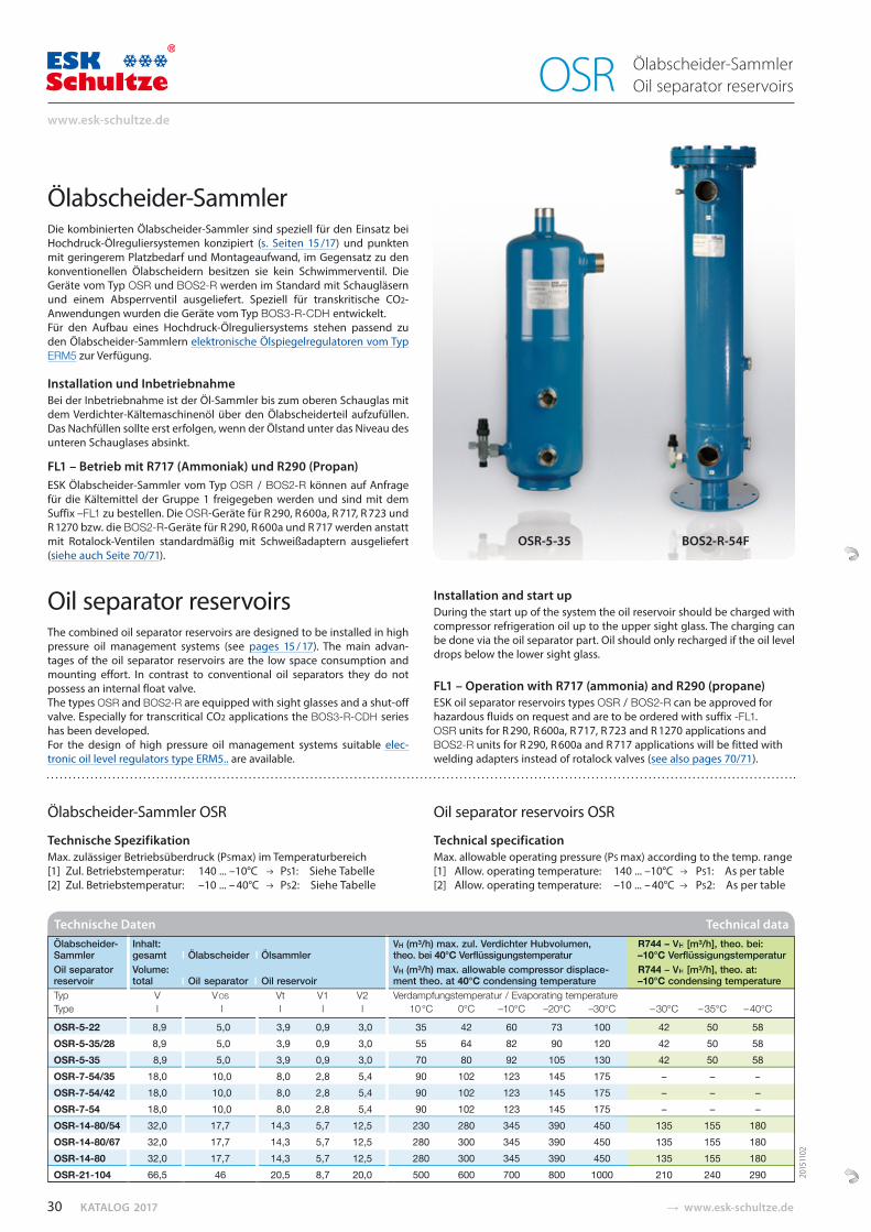
KATALOG 2017 � www.esk-schultze.de
Ölabscheider-Sammler Oil separator reservoirs OSR
Ölabscheider-Sammler OSR
Technische Spezifikation Max. zulässiger Betriebsüberdruck (PSmax) im Temperaturbereich[1] Zul. Betriebstemperatur: 140 ... –10°C PS1: Siehe Tabelle[2] Zul. Betriebstemperatur: –10 ... – 40°C PS2: Siehe Tabelle
Oil separator reservoirs OSR
Technical specification Max. allowable operating pressure (PS max) according to the temp. range[1] Allow. operating temperature: 140 ... –10°C PS1: As per table[2] Allow. operating temperature: –10 ... – 40°C PS2: As per table
Ölabscheider- Inhalt: VH (m³/h) max. zul. Verdichter Hubvolumen, R744 – VH [m³/h], theo. bei: Sammler gesamt I Ölabscheider I Ölsammler theo. bei 40°C Verflüssigungstemperatur –10°C VerflüssigungstemperaturOil separator Volume: VH (m³/h) max. allowable compressor displace- R744 – VH [m³/h], theo. at:
reservoir total I Oil separator I Oil reservoir ment theo. at 40°C condensing temperature –10°C condensing temperature Typ V V OS Vt V1 V2 Verdampfungstemperatur / Evaporating temperature
Type l l l l l 10 °C 0°C –10°C –20°C –30°C – 30°C – 35°C – 40°C
OSR-5-22 8,9 5,0 3,9 0,9 3,0 35 42 60 73 100 42 50 58 OSR-5-35/28 8,9 5,0 3,9 0,9 3,0 55 64 82 90 120 42 50 58 OSR-5-35 8,9 5,0 3,9 0,9 3,0 70 80 92 105 130 42 50 58 OSR-7-54/35 18,0 10,0 8,0 2,8 5,4 90 102 123 145 175 – – –
OSR-7-54/42 18,0 10,0 8,0 2,8 5,4 90 102 123 145 175 – – – OSR-7-54 18,0 10,0 8,0 2,8 5,4 90 102 123 145 175 – – – OSR-14-80/54 32,0 17,7 14,3 5,7 12,5 230 280 345 390 450 135 155 180 OSR-14-80/67 32,0 17,7 14,3 5,7 12,5 280 300 345 390 450 135 155 180 OSR-14-80 32,0 17,7 14,3 5,7 12,5 280 300 345 390 450 135 155 180 OSR-21-104 66,5 46 20,5 8,7 20,0 500 600 700 800 1000 210 240 290
Technische Daten Technical dataR744 – VH [m³/h], theo. bei:–10°C VerflüssigungstemperaturR744 – VH [m³/h], theo. at: –10°C condensing temperature
– 30°C – 35°C – 40°C
42 50 58 42 50 58
42 50 58 – – –– – –– – –
135 155 180 135 155 180 135 155 180 210 240 290 20
1511
02
Ölabscheider-SammlerDie kombinierten Ölabscheider-Sammler sind speziell für den Einsatz bei Hochdruck-Ölreguliersystemen konzipiert (s. Seiten 15 /17) und punkten mit geringerem Platzbedarf und Montageaufwand, im Gegensatz zu den konventionellen Ölabscheidern besitzen sie kein Schwimmerventil. Die Geräte vom Typ OSR und BOS2-R werden im Standard mit Schaugläsern und einem Absperrventil ausgeliefert. Speziell für transkritische CO2-Anwendungen wurden die Geräte vom Typ BOS3-R-CDH entwickelt. Für den Aufbau eines Hochdruck-Ölreguliersystems stehen passend zu den Ölabscheider-Sammlern elektronische Ölspiegelregulatoren vom Typ ERM5 zur Verfügung.
Installation und InbetriebnahmeBei der Inbetriebnahme ist der Öl-Sammler bis zum oberen Schauglas mit dem Verdichter-Kältemaschinenöl über den Ölabscheiderteil aufzufüllen.Das Nachfüllen sollte erst erfolgen, wenn der Ölstand unter das Niveau des unteren Schauglases absinkt.
FL1 – Betrieb mit R717 (Ammoniak) und R290 (Propan)ESK Ölabscheider-Sammler vom Typ OSR / BOS2-R können auf Anfrage für die Kältemittel der Gruppe 1 freigegeben werden und sind mit dem Suffix –FL1 zu bestellen. Die OSR-Geräte für R 290, R 600a, R 717, R 723 und R 1270 bzw. die BOS2-R-Geräte für R 290, R 600a und R 717 werden anstatt mit Rotalock-Ventilen standardmäßig mit Schweiß adaptern ausgeliefert (siehe auch Seite 70/71).
Oil separator reservoirsThe combined oil separator reservoirs are designed to be installed in high pressure oil management systems (see pages 15 / 17). The main advan-tages of the oil separator reservoirs are the low space consumption and mounting effort. In contrast to conventional oil separators they do not possess an internal float valve. The types OSR and BOS2-R are equipped with sight glasses and a shut-off valve. Especially for transcritical CO2 applications the BOS3-R-CDH series has been developed.For the design of high pressure oil management systems suitable elec-tronic oil level regulators type ERM5.. are available.
Installation and start upDuring the start up of the system the oil reservoir should be charged with compressor refrigeration oil up to the upper sight glass. The charging can be done via the oil separator part. Oil should only recharged if the oil level drops below the lower sight glass.
FL1 – Operation with R717 (ammonia) and R290 (propane)ESK oil separator reservoirs types OSR / BOS2-R can be approved for hazardous fluids on request and are to be ordered with suffix -FL1.OSR units for R 290, R 600a, R 717, R 723 and R 1270 applications and BOS2-R units for R 290, R 600a and R 717 applications will be fitted with welding adapters instead of rotalock valves (see also pages 70/71).
OSR-5-35 BOS2-R-54F
30
www.esk-schultze.de
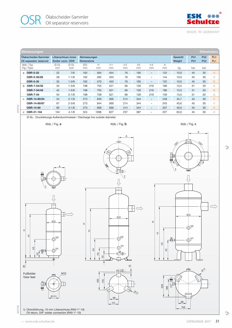
� www.esk-schultze.de CATALOGUE 2017
Abmessungen Dimensions
Ölabscheider-Sammler Oil separator reservoirs OSR
Ölabscheider-Sammler Lötanschluss innen Abmessungen Gewicht PS1 PS2 FL1 Oil separator reservoir Solder conn. ODS Dimensions Weight PS1 PS2 FL1
Abb. / Typ Ø DL Ø DL ØD H h 1 h 2 h3 h 4 A Fig. / Type mm inch mm mm mm mm mm mm mm kg bar bar
a OSR-5-22 22 7/8 162 564 454 76 195 – 122 10,0 45 30 ○
a OSR-5-35/28 28 1-1/8 162 592 453 76 195 – 144 10,0 45 30 ○
a OSR-5-35 35 1-3/8 162 570 453 76 195 – 122 10,0 45 30 ○
b OSR-7-54/35 35 1-3/8 198 755 521 66 126 216 186 13,5 31 20 ○
b OSR-7-54/42 42 1-5/8 198 755 521 66 126 216 186 13,5 31 20 ○
b OSR-7-54 54 2-1/8 198 728 521 66 126 216 159 13,5 31 20 ○
c OSR-14-80/54 54 2-1/8 273 849 569 214 344 – 248 45,7 45 30 ○
c OSR-14-80/67 67 2-5/8 273 844 569 214 344 – 243 45,6 45 30 ○
c OSR-14-80 80 3-1/8 273 808 569 214 344 – 207 40,0 45 30 ○ c OSR-21-104 104 4-1/8 324 1098 827 237 387 – 227 63,0 45 30 ○
Ø DL: Druckleitungs-Außendurchmesser / Discharge line outside diameter
1) Olrückführung, 10 mm Lötanschluss (RAV-1“-10)Oil return, 3/8“ solder connection (RAV-1“-10)
FL1FL1
○
○
○
○
○
○
○
○
○
○
Abb. / Fig. a Abb. / Fig. b Abb. / Fig. c
2015
1102
2015
1102
FußbilderView feet
31
MADE IN GERMANY
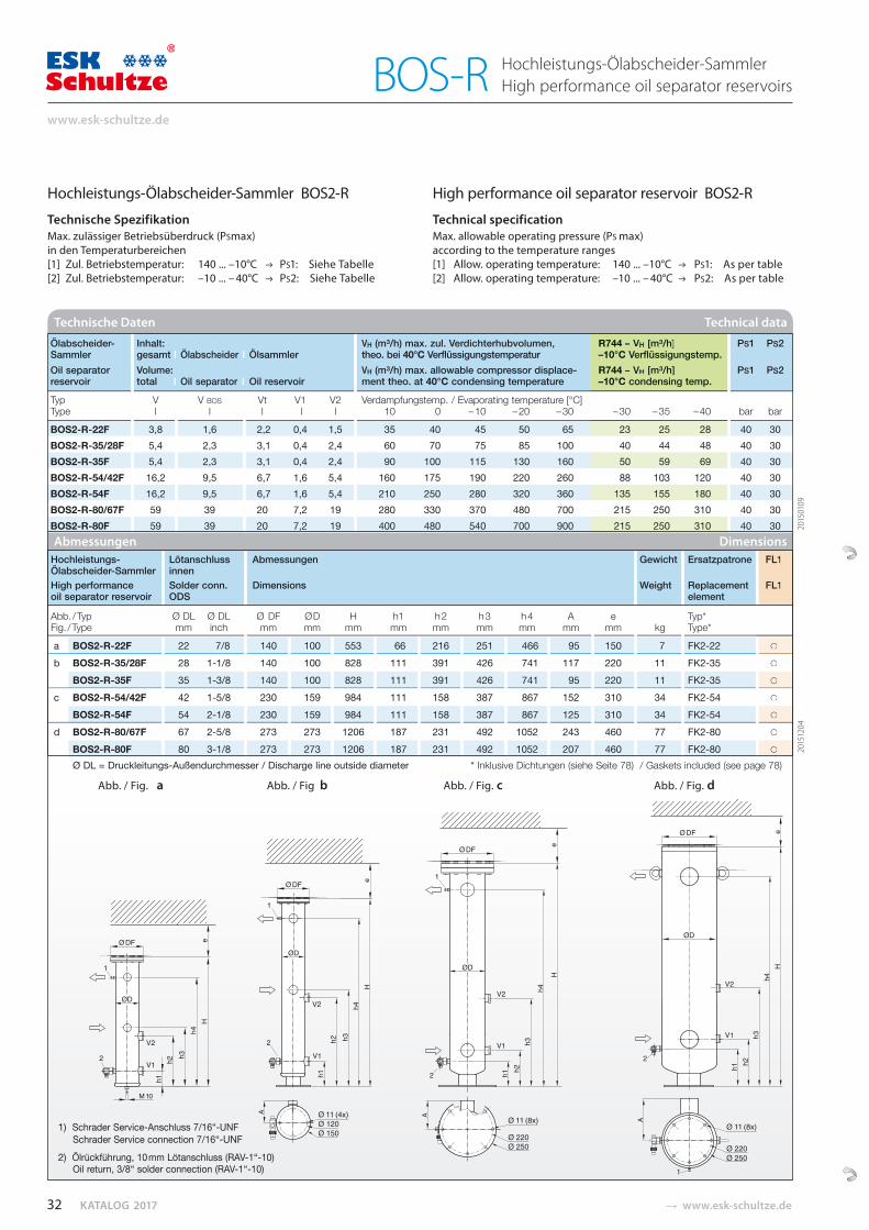
KATALOG 2017 � www.esk-schultze.de
Hochleistungs-Ölabscheider-Sammler High performance oil separator reservoirs BOS-R
Hochleistungs- Lötanschluss Abmessungen Gewicht Ersatzpatrone FL1 Ölabscheider-Sammler innen High performance Solder conn. Dimensions Weight Replacement FL1 oil separator reservoir ODS element
Abb. / Typ Ø DL Ø DL Ø DF ØD H h1 h 2 h 3 h 4 A e Typ* Fig. / Type mm inch mm mm mm mm mm mm mm mm mm kg Type*
a BOS2-R-22F 22 7/8 140 100 553 66 216 251 466 95 150 7 FK2-22 ○
b BOS2-R-35/28F 28 1-1/8 140 100 828 111 391 426 741 117 220 11 FK2-35 ○
BOS2-R-35F 35 1-3/8 140 100 828 111 391 426 741 95 220 11 FK2-35 ○
c BOS2-R-54/42F 42 1-5/8 230 159 984 111 158 387 867 152 310 34 FK2-54 ○
BOS2-R-54F 54 2-1/8 230 159 984 111 158 387 867 125 310 34 FK2-54 ○
d BOS2-R-80/67F 67 2-5/8 273 273 1206 187 231 492 1052 243 460 77 FK2-80 ○
BOS2-R-80F 80 3-1/8 273 273 1206 187 231 492 1052 207 460 77 FK2-80 ○
Ø DL = Druckleitungs-Außendurchmesser / Discharge line outside diameter * Inklusive Dichtungen (siehe Seite 78) / Gaskets included (see page 78)
Abmessungen Dimensions
1) Schrader Service-Anschluss 7/16“-UNF Schrader Service connection 7/16“-UNF
2) Ölrückführung, 10 mm Lötanschluss (RAV-1“-10)Oil return, 3/8“ solder connection (RAV-1“-10)
Ölabscheider- Inhalt: VH (m³/h) max. zul. Verdichterhubvolumen, R744 – VH [m³/h] PS1 PS2 Sammler gesamt I Ölabscheider I Ölsammler theo. bei 40°C Verflüssigungstemperatur –10°C Verflüssigungstemp. Oil separator Volume: VH (m³/h) max. allowable compressor displace- R744 – VH [m³/h] PS1 PS2 reservoir total I Oil separator I Oil reservoir ment theo. at 40°C condensing temperature –10°C condensing temp.
Typ V V BOS Vt V1 V2 Verdampfungstemp. / Evaporating temperature [°C] Type l l l l l 10 0 – 10 – 20 – 30 – 30 – 35 – 40 bar bar
BOS2-R-22F 3,8 1,6 2,2 0,4 1,5 35 40 45 50 65 23 25 28 40 30 BOS2-R-35/28F 5,4 2,3 3,1 0,4 2,4 60 70 75 85 100 40 44 48 40 30 BOS2-R-35F 5,4 2,3 3,1 0,4 2,4 90 100 115 130 160 50 59 69 40 30 BOS2-R-54/42F 16,2 9,5 6,7 1,6 5,4 160 175 190 220 260 88 103 120 40 30 BOS2-R-54F 16,2 9,5 6,7 1,6 5,4 210 250 280 320 360 135 155 180 40 30 BOS2-R-80/67F 59 39 20 7,2 19 280 330 370 480 700 215 250 310 40 30 BOS2-R-80F 59 39 20 7,2 19 400 480 540 700 900 215 250 310 40 30
Technische Daten Technical data
FL1
FL1
○
○
○
○
○
○
○
D
23 25 28 40 44 48
50 59 69 88 103 120
135 155 180 215 250 310 215 250 310
– 30 – 35 – 40
R744 – VH [m³/h]–10°C Verflüssigungstemp. R744 – VH [m³/h]–10°C condensing temp.
Hochleistungs-Ölabscheider-Sammler BOS2-R
Technische Spezifikation Max. zulässiger Betriebsüberdruck (PSmax) in den Temperaturbereichen[1] Zul. Betriebstemperatur: 140 ... –10°C PS1: Siehe Tabelle[2] Zul. Betriebstemperatur: –10 ... – 40°C PS2: Siehe Tabelle
High performance oil separator reservoir BOS2-R
Technical specification Max. allowable operating pressure (PS max) according to the temperature ranges[1] Allow. operating temperature: 140 ... –10°C PS1: As per table[2] Allow. operating temperature: –10 ... – 40°C PS2: As per table
2015
0109
2015
1204
Abb. / Fig. a Abb. / Fig b Abb. / Fig. c Abb. / Fig. d
32
www.esk-schultze.de
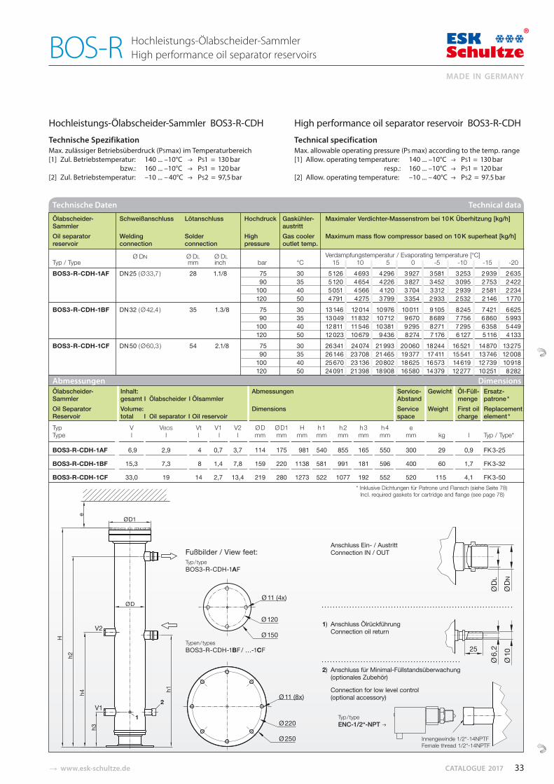
� www.esk-schultze.de CATALOGUE 2017
Hochleistungs-Ölabscheider-Sammler High performance oil separator reservoirs BOS-R
Ø D1
e
H
Ø D
2
h2
V2
V1
h3
h4 h1
1
Abmessungen Dimensions Ölabscheider- Inhalt: Abmessungen Service- Gewicht Öl-Füll- Ersatz- Sammler gesamt I Ölabscheider I Ölsammler Abstand menge patrone * Oil Separator Volume: Dimensions Service Weight First oil Replacement Reservoir total I Oil separator I Oil reservoir space charge element *
Typ V VBOS Vt V1 V2 Ø D Ø D1 H h 1 h 2 h 3 h 4 e Type l l l l l mm mm mm mm mm mm mm mm kg l Typ / Type*
BOS3-R-CDH-1AF 6,9 2,9 4 0,7 3,7 114 175 981 540 855 165 550 300 29 0,9 FK 3-25
BOS3-R-CDH-1BF 15,3 7,3 8 1,4 7,8 159 220 1138 581 991 181 596 400 60 1,7 FK 3-32
BOS3-R-CDH-1CF 33,0 19 14 2,7 13,4 219 280 1273 522 1077 192 552 520 115 4,1 FK 3-50* Inklusive Dichtungen für Patrone und Flansch (siehe Seite 78)
Incl. required gaskets for cartridge and flange (see page 78)
Hochleistungs-Ölabscheider-Sammler BOS3-R-CDH
Technische Spezifikation Max. zulässiger Betriebsüberdruck (PSmax) im Temperaturbereich[1] Zul. Betriebstemperatur: 140 ... –10°C PS1 = 130 bar
bzw.: 160 ... –10°C PS1 = 120 bar [2] Zul. Betriebstemperatur: –10 ... – 40°C PS2 = 97,5 bar
High performance oil separator reservoir BOS3-R-CDH
Technical specification Max. allowable operating pressure (PS max) according to the temp. range[1] Allow. operating temperature: 140 ... –10°C PS1 = 130 bar
resp.: 160 ... –10°C PS1 = 120 bar [2] Allow. operating temperature: –10 ... – 40°C PS2 = 97.5 bar
Technische Daten Technical data
Ölabscheider- Schweißanschluss Lötanschluss Hochdruck Gaskühler- Maximaler Verdichter-Massenstrom bei 10 K Überhitzung [kg/h] Sammler austritt Oil separator Welding Solder High Gas cooler Maximum mass flow compressor based on 10 K superheat [kg/h] reservoir connection connection pressure outlet temp.
Ø DN Ø DL Ø DL Verdampfungstemperatur / Evaporating temperature [°C] Typ / Type mm inch bar °C 15 10 5 0 -5 -10 -15 -20 BOS3-R-CDH-1AF DN 25 ( Ø 33,7 ) 28 1.1/8 75 30 5 126 4 693 4 296 3 927 3 581 3 253 2 939 2 635
90 35 5 120 4 654 4 226 3 827 3 452 3 095 2 753 2 422100 40 5 051 4 566 4 120 3 704 3 312 2 939 2 581 2 234120 50 4 791 4 275 3 799 3 354 2 933 2 532 2 146 1 770
BOS3-R-CDH-1BF DN 32 ( Ø 42,4 ) 35 1.3/8 75 30 13 146 12 014 10 976 10 011 9 105 8 245 7 421 6 62590 35 13 049 11 832 10 712 9 670 8 689 7 756 6 860 5 993
100 40 12 811 11 546 10 381 9 295 8 271 7 295 6 358 5 449120 50 12 023 10 679 9 436 8 274 7 176 6 127 5 116 4 133
BOS3-R-CDH-1CF DN 50 ( Ø 60,3 ) 54 2.1/8 75 30 26 341 24 074 21 993 20 060 18 244 16 521 14 870 13 275 90 35 26 146 23 708 21 465 19 377 17 411 15 541 13 746 12 008
100 40 25 670 23 136 20 802 18 625 16 573 14 619 12 739 10 918 120 50 24 091 21 398 18 908 16 580 14 379 12 277 10 251 8 282
Anschluss Ein- / AustrittConnection IN / OUT
1) Anschluss ÖlrückführungConnection oil return
2) Anschluss für Minimal-Füllstandsüberwachung(optionales Zubehör)
Connection for low level control(optional accessory)
Typ / type ENC-1/2“-NPT
Fußbilder / View feet:Typ / type BOS3-R-CDH-1AF
Typen / types BOS3-R-CDH-1BF / …-1CF
Innengewinde 1/2“-14NPTFFemale thread 1/2“-14NPTF
33
MADE IN GERMANY
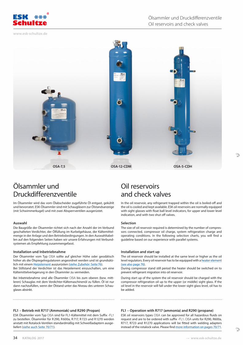
KATALOG 2017 � www.esk-schultze.de
Ölsammler undDruckdifferenzventileIm Ölsammler wird das vom Ölabscheider zugeführte Öl entgast, gekühlt und bevorratet. ESK-Ölsammler sind mit Schaugläsern zur Öl stands anzeige (mit Schwim merkugel) und mit zwei Ab sperrventilen ausgerüstet.
Auswahl Die Baugröße der Ölsammler richtet sich nach der Anzahl der im Verbund geschalteten Verdichter, der Ölfüllung im Kurbelgehäuse, der Kältemittel-menge in der Anlage und den Betriebsbedingungen. In den Auswahltabel-len auf den folgenden Seiten haben wir unsere Erfahrungen mit Verbund-sys te men als Empfehlung zusammen gefasst.
Installation und Inbetriebnahme Der Ölsammler vom Typ OSA sollte auf gleicher Höhe oder geodä tisch höher als die Ölspiegelregulatoren angeordnet werden und ist grundsätz-lich mit einem Heizelement auszurüsten (siehe Zubehör: Seite 76). Bei Still stand der Verdichter ist das Heizelement einzuschalten, um eine Kältemittel ver lage rung in den Ölsammler zu vermeiden.
Bei Inbetriebnahme sind alle Ölsammler OSA bis zum oberen (bzw. mitt-leren) Schauglas mit dem Verdichter-Kältemaschinenöl zu füllen. Öl ist nur dann nachzufüllen, wenn der Ölstand unter das Niveau des unteren Schau-glases absinkt.
FL1 – Betrieb mit R717 (Ammoniak) und R290 (Propan)ESK Ölsammler vom Typ OSA sind für FL1-Kältemittel mit dem Suffix -FL1 zu bestellen. Ölsammler für R 290, R 600a, R 717, R 723 und R 1270 werden anstatt mit Rotalock-Ventilen standardmäßig mit Schweiß adaptern ausge-liefert (siehe auch Seite 70/71).
Oil reservoirs and check valvesIn the oil reservoir, any refrigerant trapped within the oil is boiled-off and the oil is cooled and kept available. ESK oil reservoirs are normally equipped with sight glasses with float ball level indicators, for upper and lower level indication, and with two shut off valves.
SelectionThe size of oil reservoir required is determined by the number of compres-sors connected, compressor oil charge, system refrigeration charge and operating conditions. In the following selection charts, you will find a guideline based on our experience with parallel systems.
Installation and start upThe oil reservoir should be installed at the same level or higher as the oil level regulators. Every oil reservoir has to be equipped with a heater element (see also page 76). During compressor stand still period the heater should be switched on to prevent refrigerant migration into oil reservoir.
During start up of the system the oil reservoir should be charged with the compressor refrigeration oil up to the upper (or middle) sight glass. If the oil level in the reservoir will fall under the lower sight glass level, oil has to be added.
FL1 – Operation with R717 (ammonia) and R290 (propane)ESK oil reservoirs types OSA can be approved for all hazardous fluids on request and are to be ordered with suffix -FL1. OSA units for R290, R600a, R717, R723 and R1270 applications will be fitted with welding adapters instead of the rotalock valve. Please find more information on pages 70/71.
Ölsammler und Druckdifferenzventile Oil reservoirs and check valves
OSA-7,5 OSA-12-CDM OSA-5-CDH
34
www.esk-schultze.de
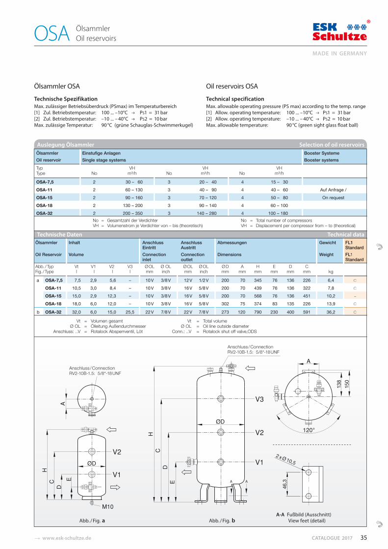
� www.esk-schultze.de CATALOGUE 2017
Technische Daten Technical data Ölsammler Inhalt Anschluss Anschluss Abmessungen Gewicht FL1
Eintritt Austritt Standard Oil Reservoir Volume Connection Connection Dimensions Weight FL1
inlet outlet Standard Abb. / Typ Vt V1 V2 V3 Ø OL Ø OL Ø OL Ø OL Ø D A H E D C Fig. / Type l l l l mm inch mm inch mm mm mm mm mm mm kg
a OSA-7,5 7,5 2,9 5,6 – 10 V 3/8 V 12 V 1/2 V 200 70 345 76 136 226 6,4 ○
a OSA-11 10,5 3,0 8,4 – 10 V 3/8 V 16 V 5/8 V 200 70 439 76 136 322 7,8 ○
a OSA-15 15,0 2,9 12,3 – 10 V 3/8 V 16 V 5/8 V 200 70 568 76 136 451 10,2 –
a OSA-18 18,0 6,0 12,0 – 10 V 3/8 V 16 V 5/8 V 302 75 374 83 135 226 13,9 ○
b OSA-32 32,0 6,0 15,0 25,5 22 V 7/8 V 22 V 7/8 V 273 120 790 230 400 591 36,2 ○
Vt = Volumen gesamt Vt = Total volume Ø OL = Ölleitung Außendurchmesser Ø OL = Oil line outside diameter
Anschluss: ..V = Rotalock Absperrventil, Löt Conn.: ..V = Rotalock shut off valve,ODS
FL1StandardFL1Standard
○
○
–
○
○
Auslegung Ölsammler Selection of oil reservoirs Ölsammler Einstufige Anlagen Booster Systeme Oil reservoir Single stage systems Booster systems
Typ VH VH VH Type No m³/h No m³/h No m³/h
OSA-7,5 2 30 – 60 3 20 – 40 4 15 – 30 OSA-11 2 60 – 130 3 40 – 90 4 40 – 60 Auf Anfrage / OSA-15 2 90 – 160 3 70 – 120 4 50 – 80 On request OSA-18 2 130 – 200 3 90 – 140 4 60 – 100 OSA-32 2 200 – 350 3 140 – 280 4 100 – 180
No = Gesamtzahl der Verdichter No = Total number of compressorsVH = Volumenstrom je Verdichter von – bis (theoretisch) VH = Displacement per compressor from – to (theoretical)
Ölsammler OSA
Technische Spezifikation Max. zulässiger Betriebsüberdruck (PSmax) im Temperaturbereich[1] Zul. Betriebstemperatur: 100 ... –10°C PS1 = 31 bar [2] Zul. Betriebstemperatur: –10 ... – 40°C PS2 = 10 barMax. zulässige Temperatur: 90 °C (grüne Schauglas-Schwimmerkugel)
Oil reservoirs OSA
Technical specification Max. allowable operating pressure (PS max) according to the temp. range[1] Allow. operating temperature: 100 ... –10°C PS1 = 31 bar[2] Allow. operating temperature: –10 ... – 40°C PS2 = 10 barMax. allowable temperature: 90 °C (green sight glass float ball)
Abb. / Fig. a Abb. / Fig. b
Ölsammler Oil reservoirs OSA
Anschluss / ConnectionRV2-10B-1.5: 5/8“-18 UNF
Anschluss / ConnectionRV2-10B-1.5: 5/8“-18 UNF
A-A Fußbild (Ausschnitt) View feet (detail)
35
MADE IN GERMANY
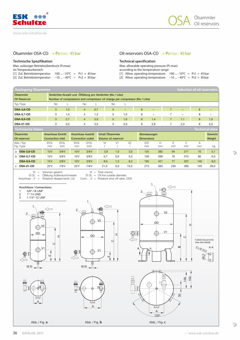
KATALOG 2017 � www.esk-schultze.de
ØD
ØD
Ölsammler OSA-CD PSmax : 45 bar
Technische Spezifikation Max. zulässiger Betriebsüberdruck (PSmax) im Temperaturbereich[1] Zul. Betriebstemperatur: 100 ... –10°C PS1 = 45 bar [2] Zul. Betriebstemperatur: –10 ... – 40°C PS2 = 30 bar
Oil reservoirs OSA-CD PSmax : 45 bar
Technical specification Max. allowable operating pressure (PS max) according to the temperature range[1] Allow. operating temperature: 100 ... –10°C PS1 = 45 bar[2] Allow. operating temperature: –10 ... – 40°C PS2 = 30 bar
Auslegung Ölsammler Selection of oil reservoirs Ölsammler Verdichter-Anzahl und -Ölfüllung pro Verdichter (No / Liter) Oil Reservoir Number of compressors and compressor oil charge per compressor (No / Litre)
Typ / Type No L No L No L
OSA-3,8-CD 3 1,0 4 0,7 5 – 6 – 7 – 8 – OSA-5,7-CD 3 1,5 4 1,2 5 1,0 6 – 7 – 8 – OSA-9,6-CD 3 2,7 4 2,0 5 1,6 6 1,4 7 1,1 8 1,0 OSA-21-CD 3 5,0 4 3,5 5 3,0 6 2,8 7 2,3 8 2,0
Technische Daten Technical data Ölsammler Anschluss Eintritt Anschluss Austritt Inhalt Ölsammler Abmessungen Gewicht Oil reservoir Connection inlet Connection outlet Volume oil reservoir Dimensions WeightAbb. / Typ Ø OL Ø OL Ø OL Ø OL Vt V1 V2 Ø D H E C A Fig. / type mm inch mm inch l l l mm mm mm mm mm kg
a OSA-3,8-CD 10 V 3/8 V 10 V 3/8 V 3,8 1,0 3,0 125 382 94 277 70 5,1 b OSA-5,7-CD 10 V 3/8 V 10 V 3/8 V 5,7 0,9 5,2 159 399 76 310 80 6,0
b OSA-9,6-CD 10 V 3/8 V 10 V 3/8 V 9,6 1,3 8,2 195 421 77 322 140 8,0 c OSA-21-CD 22 V 7/8 V 22 V 7/8 V 21,0 6,0 15,0 273 563 230 390 120 28,0
Vt = Volumen gesamt Vt = Total volume Ø OL = Ölleitung Außendurchmesser Ø OL = Oil line outside diameter
Anschluss: ..V = Rotalock Absperrventil, Löt Conn.: ..V = Rotalock shut off valve, ODS
Anschlüsse / Connections:1 5/8“-18 UNF2 1”-14 UNS3 1.1/4”-12 UNF
Abb. / Fig. a Abb. / Fig. b Abb. / Fig. c
Ölsammler Oil reservoirs OSA
36
www.esk-schultze.de
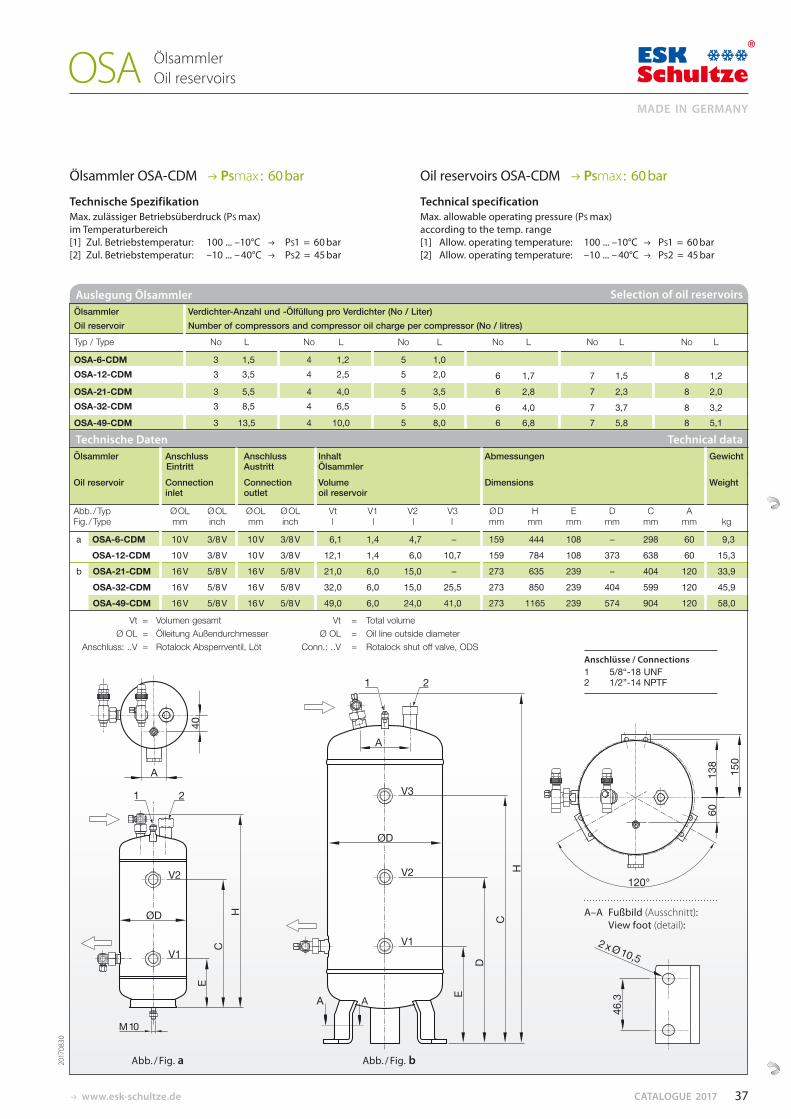
www.esk-schultze.de CATALOGUE 2017
Ölsammler OSA-CDM PSmax : 60 bar
Technische Spezifikation Max. zulässiger Betriebsüberdruck (PS max) im Temperaturbereich[1] Zul. Betriebstemperatur: 100 ... –10°C PS1 = 60 bar [2] Zul. Betriebstemperatur: –10 ... – 40°C PS2 = 45 bar
Oil reservoirs OSA-CDM PSmax : 60 bar
Technical specification Max. allowable operating pressure (PS max) according to the temp. range[1] Allow. operating temperature: 100 ... –10°C PS1 = 60 bar[2] Allow. operating temperature: –10 ... – 40°C PS2 = 45 bar
Auslegung Ölsammler Selection of oil reservoirs Ölsammler Verdichter-Anzahl und -Ölfüllung pro Verdichter (No / Liter) Oil reservoir Number of compressors and compressor oil charge per compressor (No / litres)
Typ / Type No L No L No L No L No L No L
OSA-6-CDM 3 1,5 4 1,2 5 1,0 OSA-12-CDM 3 3,5 4 2,5 5 2,0 6 1,7 7 1,5 8 1,2 OSA-21-CDM 3 5,5 4 4,0 5 3,5 6 2,8 7 2,3 8 2,0 OSA-32-CDM 3 8,5 4 6,5 5 5,0 6 4,0 7 3,7 8 3,2 OSA-49-CDM 3 13,5 4 10,0 5 8,0 6 6,8 7 5,8 8 5,1
ØD
ØD
Abb. / Fig. a Abb. / Fig. b
Ölsammler Oil reservoirs OSA
A–A Fußbild (Ausschnitt): View foot (detail):
Ölsammler Anschluss Anschluss Inhalt Abmessungen Gewicht Eintritt Austritt Ölsammler
Oil reservoir Connection Connection Volume Dimensions Weightinlet outlet oil reservoir
Abb. / Typ Ø OL Ø OL Ø OL Ø OL Vt V1 V2 V3 Ø D H E D C A Fig. / Type mm inch mm inch l l l l mm mm mm mm mm mm kg
a OSA-6-CDM 10 V 3/8 V 10 V 3/8 V 6,1 1,4 4,7 – 159 444 108 – 298 60 9,3 a OSA-12-CDM 10 V 3/8 V 10 V 3/8 V 12,1 1,4 6,0 10,7 159 784 108 373 638 60 15,3 b OSA-21-CDM 16 V 5/8 V 16 V 5/8 V 21,0 6,0 15,0 – 273 635 239 – 404 120 33,9
b OSA-32-CDM 16 V 5/8 V 16 V 5/8 V 32,0 6,0 15,0 25,5 273 850 239 404 599 120 45,9 b OSA-49-CDM 16 V 5/8 V 16 V 5/8 V 49,0 6,0 24,0 41,0 273 1165 239 574 904 120 58,0
Vt = Volumen gesamt Vt = Total volume Ø OL = Ölleitung Außendurchmesser Ø OL = Oil line outside diameter
Anschluss: ..V = Rotalock Absperrventil, Löt Conn.: ..V = Rotalock shut off valve, ODS
Technische Daten Technical data
Anschlüsse / Connections1 5/8“-18 UNF2 1/2”-14 NPTF
2017
0830
37
MADE IN GERMANY
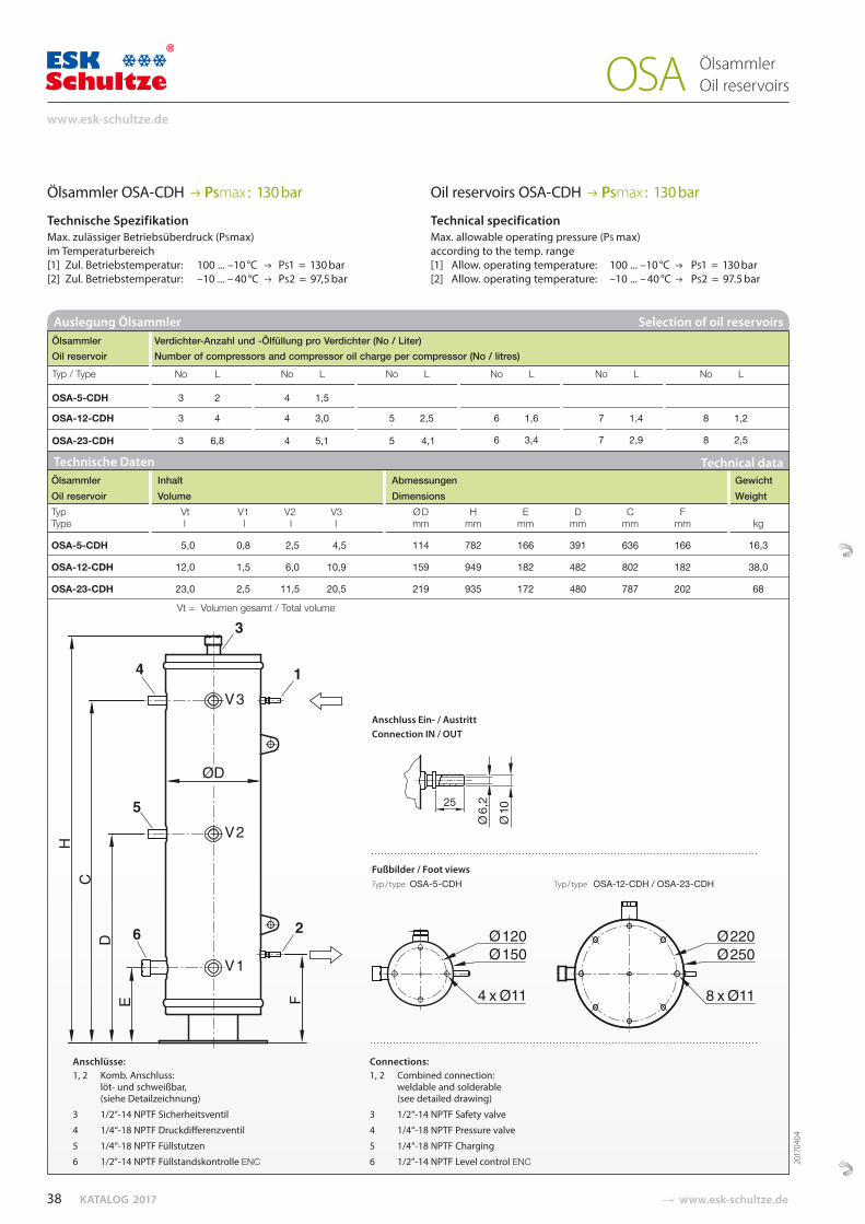
KATALOG 2017 � www.esk-schultze.de
Ölsammler OSA-CDH PSmax : 130 bar
Technische Spezifikation Max. zulässiger Betriebsüberdruck (PSmax) im Temperaturbereich[1] Zul. Betriebstemperatur: 100 ... –10 °C PS1 = 130 bar [2] Zul. Betriebstemperatur: –10 ... – 40 °C PS2 = 97,5 bar
Oil reservoirs OSA-CDH PSmax : 130 bar
Technical specification Max. allowable operating pressure (PS max) according to the temp. range[1] Allow. operating temperature: 100 ... –10 °C PS1 = 130 bar[2] Allow. operating temperature: –10 ... – 40 °C PS2 = 97.5 bar
Selection of oil reservoirs Ölsammler Verdichter-Anzahl und -Ölfüllung pro Verdichter (No / Liter) Oil reservoir Number of compressors and compressor oil charge per compressor (No / litres)
Typ / Type No L No L No L No L No L No L
OSA-5-CDH 3 2 4 1,5
OSA-12-CDH 3 4 4 3,0 5 2,5 6 1,6 7 1,4 8 1,2
OSA-23-CDH 3 6,8 4 5,1 5 4,1 6 3,4 7 2,9 8 2,5
Auslegung Ölsammler
Ölsammler Oil reservoirs OSA
Technische Daten Technical data Ölsammler Inhalt Abmessungen Gewicht Oil reservoir Volume Dimensions Weight Typ Vt V1 V2 V3 ØD H E D C F Type l l l l mm mm mm mm mm mm kg
OSA-5-CDH 5,0 0,8 2,5 4,5 114 782 166 391 636 166 16,3
OSA-12-CDH 12,0 1,5 6,0 10,9 159 949 182 482 802 182 38,0
OSA-23-CDH 23,0 2,5 11,5 20,5 219 935 172 480 787 202 68
Vt = Volumen gesamt / Total volume
F
Anschlüsse:1, 2 Komb. Anschluss:
löt- und schweißbar, (siehe Detailzeichnung)
3 1/2“-14 NPTF Sicherheitsventil
4 1/4“-18 NPTF Druckdifferenzventil
5 1/4“-18 NPTF Füllstutzen
6 1/2”-14 NPTF Füllstandskontrolle ENC
Connections:1, 2 Combined connection:
weldable and solderable (see detailed drawing)
3 1/2“-14 NPTF Safety valve
4 1/4“-18 NPTF Pressure valve
5 1/4“-18 NPTF Charging
6 1/2”-14 NPTF Level control ENC 2017
0404
Fußbilder / Foot viewsTyp / type OSA-5-CDH Typ / type OSA-12-CDH / OSA-23-CDH
Anschluss Ein- / Austritt Connection IN / OUT
38
www.esk-schultze.de
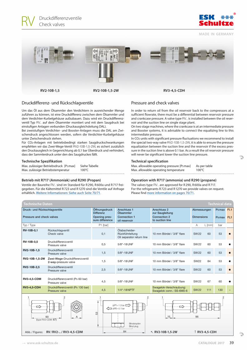
� www.esk-schultze.de CATALOGUE 2017
Druckdifferenz- und Rückschlagventile
Um das Öl aus dem Ölsammler den Verdichtern in ausreichender Menge zuführen zu können, ist eine Druckdifferenz zwi schen dem Ölsammler und dem Verdichter-Kurbel ge häu se aufzubauen. Dazu wird ein Druck dif fe renz -ventil Typ RV.. auf dem Ölsammler montiert und mit dem Saug druck bei einstufigen Anlagen verbunden (Druckaus gleichs leitung DAL). Bei zweistufigen Verdichter- und Booster-Anlagen muss die DAL am Zwi-schendruck angeschlossen werden, sofern die Ver dichter-Kurbelgehäuse unter Zwischen druck stehen. Für CO2-Anlagen mit be triebsbedingt starken Saugdruckschwankungen empfehlen wir das Zwei-Wege-Ventil RV2-10B-1,5-2W, es sichert zusätzlich den Druckausgleich in Gegenrichtung ab 0,1 bar Überdruck und verhindert, dass der Sammlerdruck unter den des Saugdruckes fällt.
Technische Spezifikation Max. zulässiger Betriebsdruck [PS max] Siehe Tabelle Max. zulässige Betriebstemperatur 100°C
Betrieb mit R717 (Ammoniak) und R290 (Propan) Ventile der Baureihe RV.. sind im Standard für R 290, R 600a und R 717 frei-gegeben. Für die Kältemittel R 723 und R 1270 sind die Ventile auf Anfrage erhältlich. Weitere Informationen: Siehe auch Seite 70/71.
Pressure and check valves
In order to return oil from the oil reservoir back to the com pres sors at a sufficient flowrate, there must be a differential bet ween reservoir pressure and crankcase pressure. A valve type RV.. is installed between the oil reser-voir and the suction line on single stage plant. On two stage machines, where the crankcase is at an intermediate pressure and Booster systems, it is advisable to connect the equalizing line to this intermediate pressure. In CO2 units with significant pressure fluctuations we recommend to install the special two-way valve RV2-10B-1,5-2W, it is able to ensure the pressure equalization between the suction line and the reservoir if the excess pres-sure in the suction line is above 0.1 bar. As a result the oil reservoir pressure will never be significant lower the suction line pressure.
Technical specification Max. allowable operating pressure [PS max] As per table Max. allowable operating temperature 100°C
Operation with R717 (ammonia) und R290 (propane) The valves type RV.. are approved for R 290, R 600a and R 717. For the refrigerants R 723 and R 1270 we provide valves on request. Please find more information on pages 70/71.
Technische Daten Technical data
Druck- und Rückschlagventile Öffnungsdruck Anschluss 1 Anschluss 2 Abmessungen PS max FL1Differenz Ölsammler zur Saugleitung
Pressure and check valves Opening pres- Connection 1 Connection 2 Dimensions PS max FL1sure difference oil reservoir to suction line
Typ / Type P1 [bar] A L [mm] bar
RV-10B-0,1 Rückschlagventil Ölabscheider-Check valve 0,1 Rückführleitung 10 mm Bördel / 3/8” flare SW 22 60 53 ●
Oil separator return line RV-10B-0,5 Druckdifferenzventil
0,5 5/8“-18 UNF 10 mm Bördel / 3/8” flare SW 22 60 53 ●Pressure valve
RV2-10B-1,5 Druckdifferenzventil 1,5 5/8“-18 UNF 10 mm Bördel / 3/8” flare SW 22 60 53 ●Pressure valve
RV2-10B-1,5-2W Zwei-Wege-Druckdifferenzventil 1,5 5/8“-18 UNF 10 mm Bördel / 3/8” flare SW22 84 53 ●2-way-pressure valve
RV2-10B-2,5 Druckdifferenzventil 2,5 5/8“-18 UNF 10 mm Bördel / 3/8” flare SW 22 60 53 ●Pressure valve
RV3-4,5-CDM Druckdifferenzventil (PS 60 bar) 4,5 5/8“-18 UNF 10 mm Bördel / 3/8” flare SW 22 67 60 ●Pressure valve
RV3-4,5-CDH Druckdifferenzventil (PS 130 bar) 4,5 1/4“-18 NPTF
Swagelok-Verschraubung: SW 22 111 130 –Pressure valve Swagelok conn.: SS-6M0-6
FL1
FL1
●
●
●
●
●
RV2-10B-1,5 RV2-10B-1,5-2W RV3-4,5-CDH
Druckdifferenzventile Check valves RV
(type RV3-CDM: 67)BlindstopfenBlind plug
P1 = 1.5 bar P2 = 0.1 bar
Abb. / Figures: RV / RV2-.. / RV3-4,5-CDM RV2-10B-1,5-2W ↑ RV3-4,5-CDH
39
MADE IN GERMANY
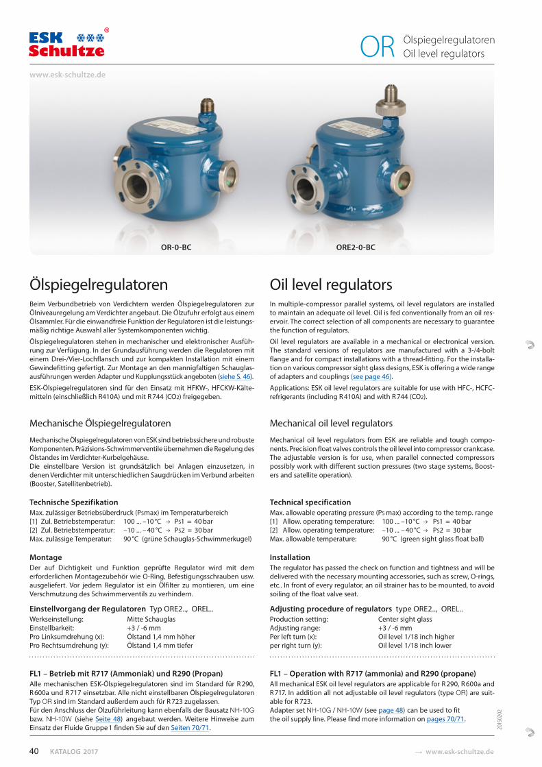
KATALOG 2017 � www.esk-schultze.de
ÖlspiegelregulatorenBeim Verbundbetrieb von Verdichtern werden Ölspiegelregulatoren zur Öl niveauregelung am Verdichter angebaut. Die Ölzufuhr erfolgt aus einem Ölsammler. Für die einwandfreie Funktion der Regulatoren ist die leis tungs-mäßig richtige Auswahl aller Systemkomponenten wichtig.
Ölspiegelregulatoren stehen in mechanischer und elektronischer Ausfüh-rung zur Verfügung. In der Grundausführung werden die Regulatoren mit einem Drei-/Vier-Loch flansch und zur kompakten Installation mit einem Gewindefitting gefertigt. Zur Montage an den mannigfaltigen Schau glas -ausführungen werden Adapter und Kupplungsstück angeboten (siehe S. 46).
ESK-Ölspiegelregulatoren sind für den Einsatz mit HFKW-, HFCKW-Kälte-mitteln (einschließlich R410A) und mit R 744 (CO2) freigegeben.
Mechanische Ölspiegelregulatoren
Mechanische Ölspiegelregulatoren von ESK sind betriebs si chere und ro buste Komponenten. Präzisions-Schwimmer ven tile übernehmen die Regelung des Ölstandes im Ver dichter-Kur belgehäuse. Die einstellbare Version ist grund sätzlich bei An lagen einzusetzen, in denen Verdichter mit unter schied li chen Saugdrücken im Verbund arbeiten (Booster, Satelliten betrieb).
Technische Spezifikation Max. zulässiger Betriebsüberdruck (PSmax) im Temperaturbereich[1] Zul. Betriebstemperatur: 100 ... –10 °C PS1 = 40 bar [2] Zul. Betriebstemperatur: –10 ... – 40 °C PS2 = 30 barMax. zulässige Temperatur: 90 °C (grüne Schauglas-Schwimmerkugel)
MontageDer auf Dichtigkeit und Funktion geprüfte Regulator wird mit dem erforderlichen Montagezubehör wie O-Ring, Be festi gungs schrauben usw. ausgeliefert. Vor jedem Regulator ist ein Ölfilter zu montieren, um eine Verschmutzung des Schwim merventils zu verhindern.
Einstellvorgang der Regulatoren Typ ORE2.., OREL..Werkseinstellung: Mitte SchauglasEinstellbarkeit: +3 / -6 mmPro Linksumdrehung (x): Ölstand 1,4 mm höher Pro Rechtsumdrehung (y): Ölstand 1,4 mm tiefer
FL1 – Betrieb mit R717 (Ammoniak) und R290 (Propan)Alle mechanischen ESK-Ölspiegelregulatoren sind im Standard für R 290, R 600a und R 717 einsetzbar. Alle nicht einstellbaren Ölspiegelregulatoren Typ OR sind im Standard außerdem auch für R 723 zugelassen. Für den Anschluss der Ölzuführlei tung kann ebenfalls der Bausatz NH-10G bzw. NH-10W (siehe Seite 48) angebaut werden. Weitere Hinweise zum Einsatz der Fluide Gruppe 1 finden Sie auf den Seiten 70/71.
Oil level regulatorsIn multiple-compressor parallel systems, oil level regulators are installed to maintain an adequate oil level. Oil is fed conventionally from an oil res-ervoir. The correct selection of all components are necessary to guarantee the function of regulators.
Oil level regulators are available in a mechanical or electronical version. The standard versions of regulators are manufactured with a 3-/4-bolt flange and for compact installations with a thread-fitting. For the installa-tion on various compressor sight glass designs, ESK is offering a wide range of adapters and couplings (see page 46).
Applications: ESK oil level regulators are suitable for use with HFC-, HCFC-refrigerants (including R 410A) and with R 744 (CO2).
Mechanical oil level regulators
Mechanical oil level regulators from ESK are reliable and tough compo-nents. Precision float valves controls the oil level into compressor crankcase. The adjustable version is for use, when parallel connected compressors possibly work with different suction pressures (two stage systems, Boost-ers and satellite operation).
Technical specification Max. allowable operating pressure (PS max) according to the temp. range[1] Allow. operating temperature: 100 ... –10 °C PS1 = 40 bar[2] Allow. operating temperature: –10 ... – 40 °C PS2 = 30 barMax. allowable temperature: 90 °C (green sight glass float ball)
InstallationThe regulator has passed the check on function and tightness and will be delivered with the necessary mounting accessories, such as screw, O-rings, etc.. In front of every regulator, an oil strainer has to be mounted, to avoid soiling of the float valve seat.
Adjusting procedure of regulators type ORE2.., OREL..Production setting: Center sight glassAdjusting range: +3 / -6 mmPer left turn (x): Oil level 1/18 inch higherper right turn (y): Oil level 1/18 inch lower
FL1 – Operation with R717 (ammonia) and R290 (propane)All mechanical ESK oil level regulators are applicable for R 290, R 600a and R 717. In addition all not adjustable oil level regulators (type OR) are suit-able for R 723. Adapter set NH-10G / NH-10W (see page 48) can be used to fit the oil supply line. Please find more information on pages 70/71.
OR-0-BC ORE2-0-BC
Ölspiegelregulatoren Oil level regulators OR
2015
0202
40
www.esk-schultze.de
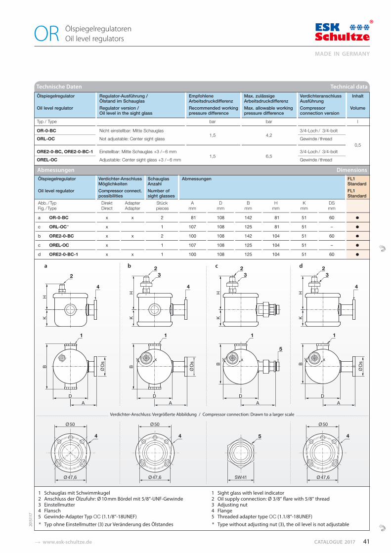
� www.esk-schultze.de CATALOGUE 2017
Ölspiegelregulatoren Oil level regulators OR
Technische Daten Technical data
Abmessungen Dimensions
a b c d
Ölspiegelregulator Verdichter-Anschluss Schauglas Abmessungen FL1 Möglichkeiten Anzahl Standard
Oil level regulator Compressor connect. Number of FL1possibilities sight glasses Standard
Abb. / Typ Direkt Adapter Stück A D B H K DS Fig. / Type Direct Adapter pieces mm mm mm mm mm mm
a OR-0-BC x x 2 81 108 142 81 51 60 ●
c ORL-OC * x 1 107 108 125 81 51 – ●
b ORE2-0-BC x x 2 100 108 142 104 51 60 ●
c OREL-OC x 1 107 108 125 104 51 – ●
d ORE2-0-BC-1 x x 1 100 108 125 104 51 60 ●
1 Schauglas mit Schwimmkugel2 Anschluss der Ölzufuhr: Ø 10 mm Bördel mit 5/8“-UNF-Gewinde
3 Einstellmutter 4 Flansch 5 Gewinde-Adapter Typ OC (1.1/8“-18UNEF)
* Typ ohne Einstellmutter (3) zur Veränderung des Ölstandes
1 Sight glass with level indicator2 Oil supply connection: Ø 3/8“ flare with 5/8“ thread
3 Adjusting nut 4 Flange
5 Threaded adapter type OC (1.1/8“-18UNEF) * Type without adjusting nut (3), the oil level is not adjustable
Verdichter-Anschluss: Vergrößerte Abbildung / Compressor connection: Drawn to a larger scale
Ölspiegelregulator Regulator-Ausführung / Empfohlene Max. zulässige Verdichteranschluss Inhalt Ölstand im Schauglas Arbeitsdruckdifferenz Arbeitsdruckdifferenz Ausführung
Oil level regulator Regulator version / Recommended working Max. allowable working Compressor Volume Oil level in the sight glass pressure difference pressure difference connection version
Typ / Type bar bar l
OR-0-BC Nicht einstellbar: Mitte Schauglas 1,5 4,2
3/4-Loch / 3/4-bolt
ORL-OC Not adjustable: Center sight glass Gewinde / thread
ORE2-0-BC, ORE2-0-BC-1 Einstellbar: Mitte Schauglas +3 / – 6 mm 1,5 6,5
3/4-Loch / 3/4-bolt 0,5
OREL-OC Adjustable: Center sight glass +3 / – 6 mm Gewinde / thread
FL1 StandardFL1 Standard
●
●
●
●
●
2015
1117
41
MADE IN GERMANY
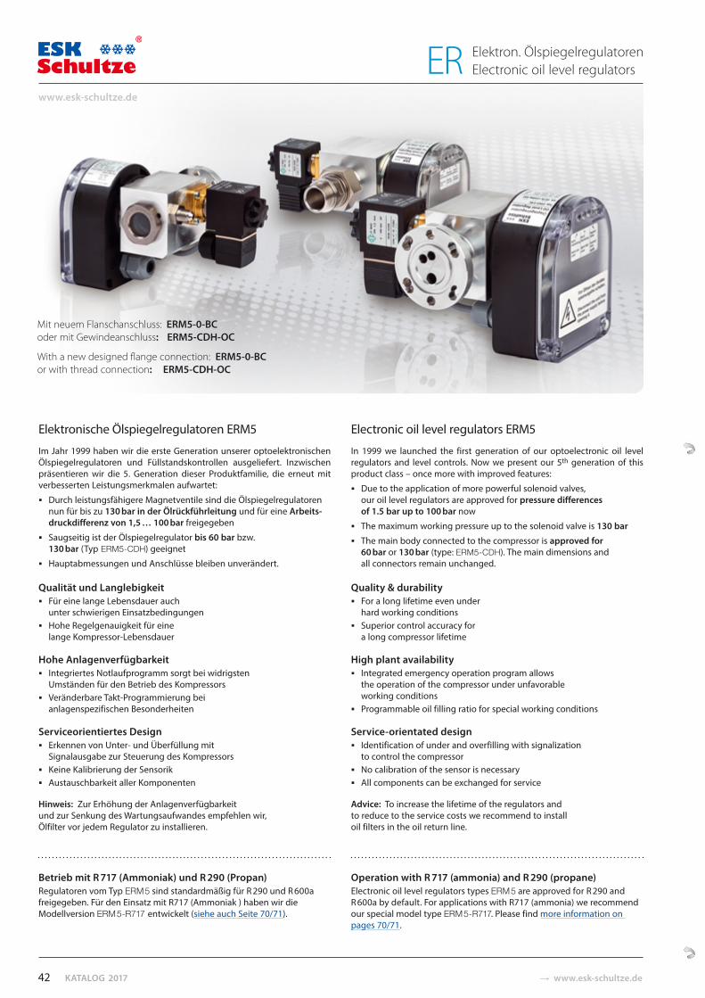
KATALOG 2017 � www.esk-schultze.de
Elektronische Ölspiegelregulatoren ERM5
Im Jahr 1999 haben wir die erste Generation unserer optoelektronischen Ölspiegelregulatoren und Füllstandskontrollen ausgeliefert. Inzwischen präsentieren wir die 5. Generation dieser Produktfamilie, die erneut mit verbesserten Leistungsmerkmalen aufwartet:
Durch leistungsfähigere Magnetventile sind die Ölspiegelregulatoren nun für bis zu 130 bar in der Ölrückführleitung und für eine Arbeits-
druckdifferenz von 1,5 … 100 bar freigegeben
Saugseitig ist der Ölspiegelregulator bis 60 bar bzw.130 bar (Typ ERM5-CDH) geeignet
Hauptabmessungen und Anschlüsse bleiben unverändert.
Qualität und LanglebigkeitFür eine lange Lebensdauer auchunter schwierigen EinsatzbedingungenHohe Regelgenauigkeit für eine lange Kompressor-Lebensdauer
Hohe AnlagenverfügbarkeitIntegriertes Notlaufprogramm sorgt bei widrigsten Umständen für den Betrieb des KompressorsVeränderbare Takt-Programmierung bei anlagenspezifischen Besonderheiten
Serviceorientiertes DesignErkennen von Unter- und Überfüllung mit Signalausgabe zur Steuerung des KompressorsKeine Kalibrierung der SensorikAustauschbarkeit aller Komponenten
Hinweis: Zur Erhöhung der Anlagenverfügbarkeit und zur Senkung des Wartungsaufwandes empfehlen wir, Ölfilter vor jedem Regulator zu installieren.
Electronic oil level regulators ERM5
In 1999 we launched the first generation of our optoelectronic oil level regulators and level controls. Now we present our 5th generation of this product class – once more with improved features:
Due to the application of more powerful solenoid valves, our oil level regulators are approved for pressure differences of 1.5 bar up to 100 bar now
The maximum working pressure up to the solenoid valve is 130 bar
The main body connected to the compressor is approved for 60 bar or 130 bar (type: ERM5-CDH). The main dimensions and all connectors remain unchanged.
Quality & durabilityFor a long lifetime even under hard working conditionsSuperior control accuracy for a long compressor lifetime
High plant availabilityIntegrated emergency operation program allows the operation of the compressor under unfavorable working conditionsProgrammable oil filling ratio for special working conditions
Service-orientated designIdentification of under and overfilling with signalization to control the compressorNo calibration of the sensor is necessaryAll components can be exchanged for service
Advice: To increase the lifetime of the regulators and to reduce to the service costs we recommend to install oil filters in the oil return line.
Mit neuem Flanschanschluss: ERM5-0-BC oder mit Gewindeanschluss: ERM5-CDH-OC
With a new designed flange connection: ERM5-0-BC or with thread connection: ERM5-CDH-OC
Betrieb mit R 717 (Ammoniak) und R 290 (Propan)Regulatoren vom Typ ERM 5 sind standardmäßig für R 290 und R 600a freigegeben. Für den Einsatz mit R717 (Ammoniak ) haben wir die Modellversion ERM 5-R717 entwickelt (siehe auch Seite 70/71).
Operation with R 717 (ammonia) and R 290 (propane)Electronic oil level regulators types ERM 5 are approved for R 290 and R 600a by default. For applications with R717 (ammonia) we recommend our special model type ERM 5-R717. Please find more information on pages 70/71.
42
www.esk-schultze.de
Elektron. Ölspiegelregulatoren Electronic oil level regulators ER
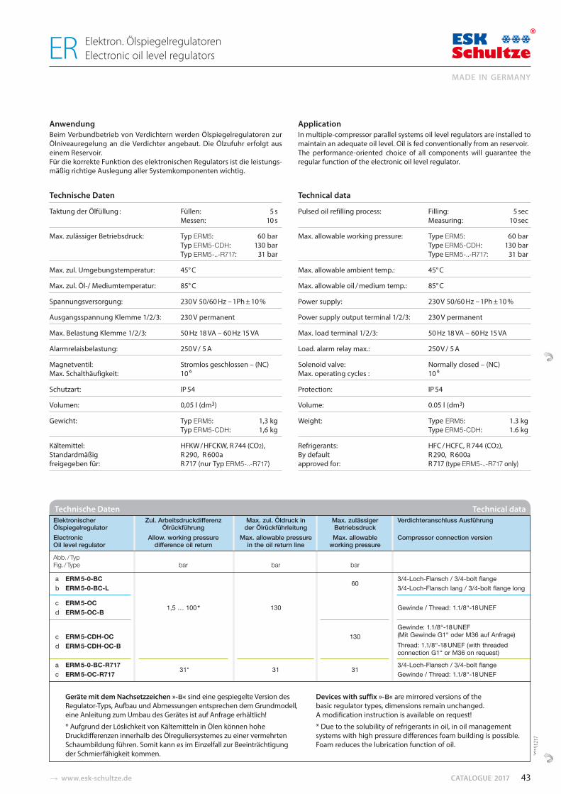
� www.esk-schultze.de CATALOGUE 2017
AnwendungBeim Verbundbetrieb von Verdichtern werden Ölspiegelregulatoren zur Ölniveauregelung an die Verdichter angebaut. Die Ölzufuhr erfolgt aus einem Reservoir. Für die korrekte Funktion des elektronischen Regulators ist die leistungs-mäßig richtige Auslegung aller Systemkomponenten wichtig.
Technische Daten
Taktung der Ölfüllung : Füllen: 5 s Messen: 10 s
Max. zulässiger Betriebsdruck: Typ ERM5: 60 bar Typ ERM5-CDH: 130 bar Typ ERM5-..-R717: 31 bar
Max. zul. Umgebungstemperatur: 45° C
Max. zul. Öl-/ Mediumtemperatur: 85° C
Spannungsversorgung: 230 V 50/60 Hz – 1Ph ± 10 %
Ausgangsspannung Klemme 1/2/3: 230 V permanent
Max. Belastung Klemme 1/2/3: 50 Hz 18 VA – 60 Hz 15 VA
Alarmrelaisbelastung: 250 V / 5 A
Magnetventil: Stromlos geschlossen – (NC)Max. Schalthäufigkeit: 10 6
Schutzart: IP 54
Volumen: 0,05 l (dm3)
Gewicht: Typ ERM5: 1,3 kg Typ ERM5-CDH: 1,6 kg
Kältemittel: HFKW / HFCKW, R 744 (CO2),Standardmäßig R 290, R 600afreigegeben für: R 717 (nur Typ ERM5-..-R717)
ApplicationIn multiple-compressor parallel systems oil level regulators are installed to maintain an adequate oil level. Oil is fed conventionally from an reservoir. The performance-oriented choice of all components will guarantee the regular function of the electronic oil level regulator.
Technical data
Pulsed oil refilling process: Filling: 5 sec Measuring: 10 sec
Max. allowable working pressure: Type ERM5: 60 bar Type ERM5-CDH: 130 bar Type ERM5-..-R717: 31 bar
Max. allowable ambient temp.: 45° C
Max. allowable oil / medium temp.: 85° C
Power supply: 230 V 50/60 Hz – 1Ph ± 10 %
Power supply output terminal 1/2/3: 230 V permanent
Max. load terminal 1/2/3: 50 Hz 18 VA – 60 Hz 15 VA
Load. alarm relay max.: 250 V / 5 A
Solenoid valve: Normally closed – (NC)Max. operating cycles : 10 6
Protection: IP 54
Volume: 0.05 l (dm3)
Weight: Type ERM5: 1.3 kg Type ERM5-CDH: 1.6 kg
Refrigerants: HFC / HCFC, R 744 (CO2),By default R 290, R 600aapproved for: R 717 (type ERM5-..-R717 only)
Technische Daten Technical data Elektronischer Zul. Arbeitsdruckdifferenz Max. zul. Öldruck in Max. zulässiger Verdichteranschluss Ausführung Ölspiegelregulator Ölrückführung der Ölrückführleitung Betriebsdruck Electronic Allow. working pressure Max. allowable pressure Max. allowable Compressor connection version Oil level regulator difference oil return in the oil return line working pressure
Abb. / Typ Fig. / Type bar bar bar
a ERM 5-0-BC 60
3/4-Loch-Flansch / 3/4-bolt flange b ERM 5-0-BC-L 3/4-Loch-Flansch lang / 3/4-bolt flange long
c ERM 5-OC 1,5 … 100 * 130 Gewinde / Thread: 1.1/8“-18 UNEF
d ERM 5-OC-B
Gewinde: 1.1/8“-18 UNEF c ERM 5-CDH-OC 130 (Mit Gewinde G1“ oder M36 auf Anfrage) d ERM 5-CDH-OC-B Thread: 1.1/8“-18 UNEF (with threaded connection G1“ or M36 on request)
a ERM 5-0-BC-R717 31* 31 31
3/4-Loch-Flansch / 3/4-bolt flange c ERM 5-OC-R717 Gewinde / Thread: 1.1/8“-18 UNEF
2015
1217
Geräte mit dem Nachsetzzeichen »-B« sind eine gespiegelte Version des Regulator-Typs, Aufbau und Abmessungen entsprechen dem Grundmodell, eine Anleitung zum Umbau des Gerätes ist auf Anfrage erhältlich!
* Aufgrund der Löslichkeit von Kältemitteln in Ölen können hohe Druck differenzen innerhalb des Ölreguliersystemes zu einer vermehrten Schaumbildung führen. Somit kann es im Einzelfall zur Beeinträchtigung der Schmierfähigkeit kommen.
Devices with suffix »-B« are mirrored versions of the basic regulator types, dimensions remain unchanged. A modification instruction is available on request!
* Due to the solubility of refrigerants in oil, in oil management systems with high pressure differences foam building is possible. Foam reduces the lubrication function of oil.
43
MADE IN GERMANY
Elektron. Ölspiegelregulatoren Electronic oil level regulators ER
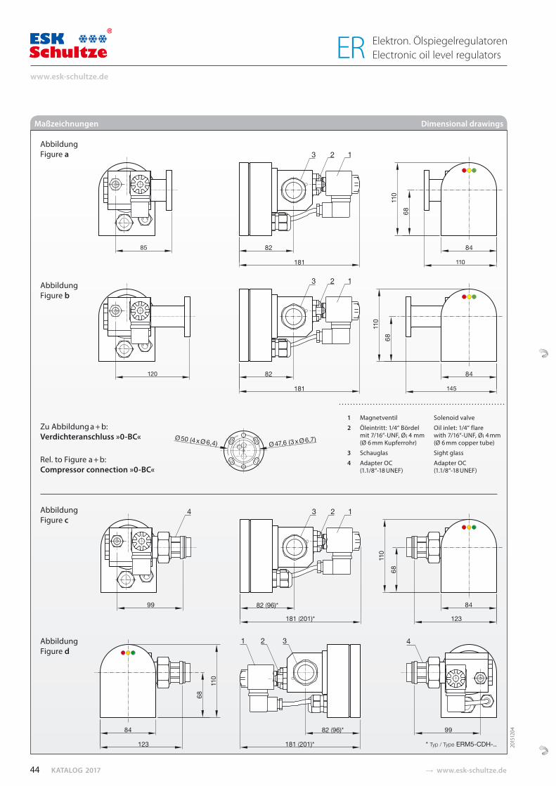
KATALOG 2017 � www.esk-schultze.de
181 (201)* 123
123
181
82 (96)*
82 (96)*
181 (201)*
85
110
181
120
145
* Typ / Type ERM5-CDH-..
Maßzeichnungen Dimensional drawings
Abbildung Figure a
Abbildung Figure b
Zu Abbildung a + b:Verdichteranschluss »0-BC«
Rel. to Figure a + b:Compressor connection »0-BC«
Abbildung Figure c
Abbildung Figure d
1 Magnetventil Solenoid valve
2 Öleintritt: 1/4“ Bördel Oil inlet: 1/4“ flare mit 7/16“-UNF, Øi 4 mm with 7/16“-UNF, Øi 4 mm (Ø 6 mm Kupferrohr) (Ø 6 mm copper tube)
3 Schauglas Sight glass
4 Adapter OC Adapter OC(1.1/8“-18 UNEF) (1.1/8“-18 UNEF)
2015
1204
44
www.esk-schultze.de
Elektron. Ölspiegelregulatoren Electronic oil level regulators ER
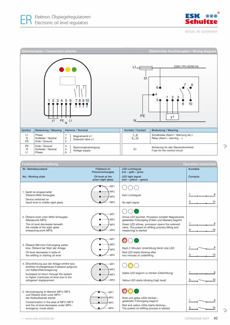
� www.esk-schultze.de CATALOGUE 2017
Nr.: Betriebszustand Füllstand im LED-Lichtsignal Kontakte Prismenschauglas (rot – gelb – grün)
No.: Working state Oil level at the LED light signal Contactsprism sight glass (red – yellow – green)
Funktionsbeschreibung Operation instruction
1. Gerät ist eingeschaltetÖlstand Mitte SchauglasDevice switched onliquid level is middle sight glass
2. Ölstand sinkt unter Mitte Schauglas(Messpunkt MP3)The oil level decreases beneaththe middle of the sight glass(measuring point MP3)
3. Ölstand fällt trotz Füllvorgang weiterbzw. Ölstand bei Start der AnlageOil level decreases in spite ofthe refilling or starting oil level
4. Ölrückführung aus der Anlage erhöht bzw.erhöhter Kurbelgehäuse-Füllstand aufgrundvon KältemittelverlagerungIncreased oil return through the systemor higher crankcase oil level due to therefrigerant displacement
5. Verunreinigung im Bereich MP 2 / MP 3und Ölstand sinkt unter MP4 –der Notlaufbetrieb startetContamination in the area of MP 2 / MP 3and the oil level decreases under MP4 –emergency mode starts
Kein Lichtsignal 7 8
No light signal 9 10
Grüne LED leuchtet, Prozessor schaltet Magnetventil, getakteter Füllvorgang (Füllen und Messen) beginntGreen LED shines, processor opens the solenoid 7 8valve. The pulsed oil refilling process (filling and measuring) is started 9 10
Nach 2 Minuten Unterfüllung blinkt rote LED 7 8
Red LED starts blinking after two minutes of underfilling 9 10
Gelbe LED beginnt zu blinken (Überfüllung) 7 8
Yellow LED starts blinking (high level) 9 10
Rote und gelbe LEDs blinken – getakteter Füllvorgang beginnt 7 8
Red and yellow LEDs starts blinking – The pulsed oil refilling process is started 9 10
Klemmenplan / Connection scheme Elektrischer Anschlussplan / Wiring diagram
Symbol Bedeutung / Meaning Klemme / Terminal Kontakt / Contact Bedeutung / Meaning
L1 Phase 1 Magnetventil y1 7 .. 8 Schaltrelais (Alarm / Warnung etc.)N Nullleiter / Neutral 2 Solenoid valve y1 9 .. 10 Relay (Alarm / warning …)PE Erde / Ground 3
PE Erde / Ground 4 N Nullleiter / Neutral 5
Spannungsversorgung S1
Sicherung für den Steuerstromkreis
L1 Phase 6 Voltage supply Fuse for the control circuit
45
MADE IN GERMANY
Elektron. Ölspiegelregulatoren Electronic oil level regulators ER
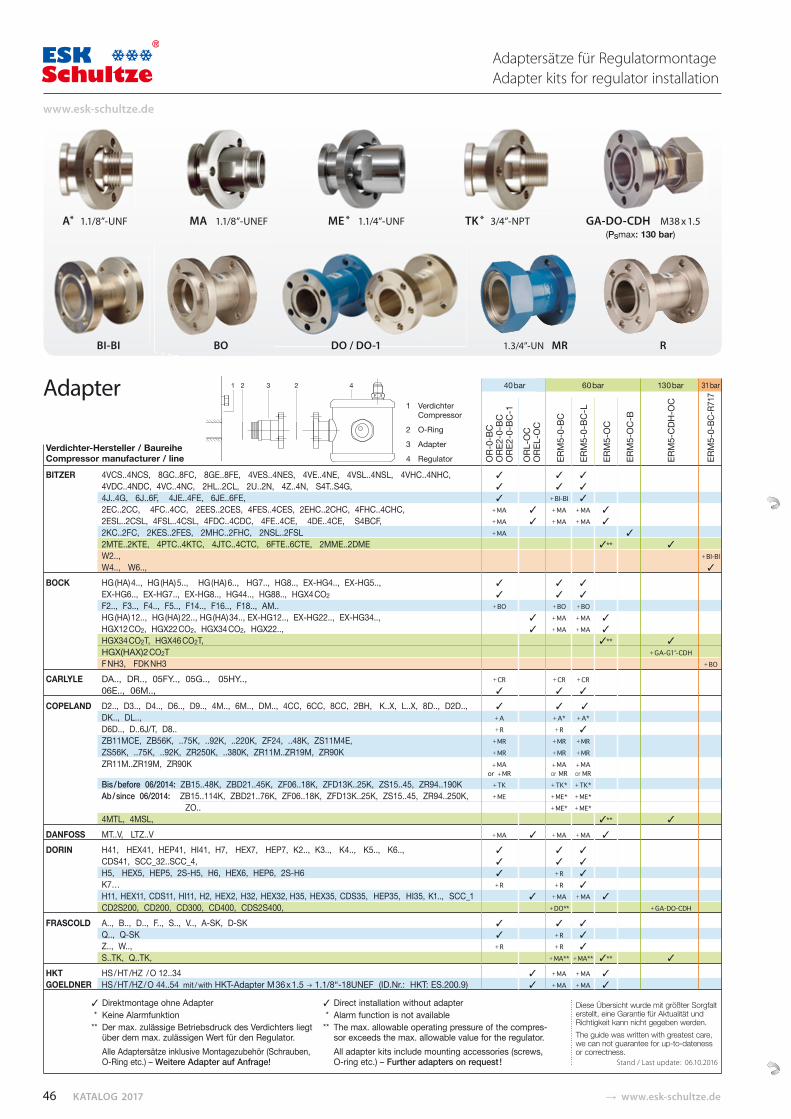
KATALOG 2017 � www.esk-schultze.de
Adaptersätze für RegulatormontageAdapter kits for regulator installation
40 bar 60 bar 130 bar 31 bar
Verdichter-Hersteller / BaureiheCompressor manufacturer / line BITZER 4VCS..4NCS, 8GC..8FC, 8GE..8FE, 4VES..4NES, 4VE..4NE, 4VSL..4NSL, 4VHC..4NHC,
4VDC..4NDC, 4VC..4NC, 2HL..2CL, 2U..2N, 4Z..4N, S4T..S4G, 4J..4G, 6J..6F, 4JE..4FE, 6JE..6FE, + BI-BI 2EC..2CC, 4FC..4CC, 2EES..2CES, 4FES..4CES, 2EHC..2CHC, 4FHC..4CHC, + MA + MA + MA 2ESL..2CSL, 4FSL..4CSL, 4FDC..4CDC, 4FE..4CE, 4DE..4CE, S4BCF, + MA + MA + MA 2KC..2FC, 2KES..2FES, 2MHC..2FHC, 2NSL..2FSL + MA2MTE..2KTE, 4PTC..4KTC, 4JTC..4CTC, 6FTE..6CTE, 2MME..2DME ** W2.., + BI-BIW4.., W6..,
BOCK HG (HA) 4.., HG (HA) 5.., HG (HA) 6.., HG7.., HG8.., EX-HG4.., EX-HG5.., EX-HG6.., EX-HG7.., EX-HG8.., HG44.., HG88.., HGX4 CO2 F2.., F3.., F4.., F5.., F14.., F16.., F18.., AM.. + BO + BO + BOHG (HA) 12.., HG (HA) 22.., HG (HA) 34.., EX-HG12.., EX-HG22.., EX-HG34.., + MA + MA HGX12 CO2, HGX22 CO2, HGX34 CO2, HGX22.., + MA + MA HGX34 CO2T, HGX46 CO2T, ** HGX(HAX)2 CO2T + GA-G1“-CDHF NH3, FDK NH3 + BO
CARLYLE DA.., DR.., 05FY.., 05G.., 05HY.., + CR + CR + CR06E.., 06M..,
COPELAND D2.., D3.., D4.., D6.., D9.., 4M.., 6M.., DM.., 4CC, 6CC, 8CC, 2BH, K..X, L..X, 8D.., D2D.., DK.., DL.., + A + A* + A*D6D.., D..6J/T, D8.. + R + RZB11MCE, ZB56K, ..75K, ..92K, ..220K, ZF24, ..48K, ZS11M4E, + MR + MR + MR ZS56K, ..75K, ..92K, ZR250K, ..380K, ZR11M..ZR19M, ZR90K + MR + MR + MR ZR11M..ZR19M, ZR90K + MA + MA + MA
or + MR or MR or MRBis / before 06/2014: ZB15..48K, ZBD21..45K, ZF06..18K, ZFD13K..25K, ZS15..45, ZR94..190K + TK + TK* + TK*Ab / since 06/2014: ZB15..114K, ZBD21..76K, ZF06..18K, ZFD13K..25K, ZS15..45, ZR94..250K, + ME + ME* + ME*
ZO.. + ME* + ME*4MTL, 4MSL, **
DANFOSS MT..V, LTZ..V + MA + MA + MA DORIN H41, HEX41, HEP41, HI41, H7, HEX7, HEP7, K2.., K3.., K4.., K5.., K6..,
CDS41, SCC_32..SCC_4, H5, HEX5, HEP5, 2S-H5, H6, HEX6, HEP6, 2S-H6 + R K7… + R + RH11, HEX11, CDS11, HI11, H2, HEX2, H32, HEX32, H35, HEX35, CDS35, HEP35, HI35, K1.., SCC_1 + MA + MA CD2S200, CD200, CD300, CD400, CDS2S400, + DO** + GA-DO-CDH
FRASCOLD A.., B.., D.., F.., S.., V.., A-SK, D-SK Q.., Q-SK + RZ.., W.., + R + RS..TK, Q..TK, + MA** + MA** **
HKT HS / HT /HZ / O 12..34 + MA + MA GOELDNER HS / HT /HZ / O 44..54 mit / with HKT-Adapter M 36 x 1.5 1.1/8“-18UNEF (ID.Nr.: HKT: ES.200.9) + MA + MA
BI-BI BO DO / DO-1 1.3/4”-UN MR R
1 2 3 2 4
1 Verdichter Compressor
2 O-Ring
3 Adapter
4 Regulator
Diese Übersicht wurde mit größter Sorgfalt erstellt, eine Garantie für Aktualität und Richtigkeit kann nicht gegeben werden. The guide was written with greatest care, we can not guarantee for up-to-dateness or correctness.
Stand / Last update: 06.10.2016
Adapter
A* 1.1/8”-UNF MA 1.1/8”-UNEF ME * 1.1/4”-UNF TK * 3/4”-NPT GA-DO-CDH M38 x 1.5 (PSmax: 130 bar)
OR-
0-BC
ORE
2-0-
BCO
RE2-
0-BC
-1
ORL
-OC
ORE
L-O
C
ERM
5-0-
BC
ERM
5-0-
BC-L
ERM
5-O
C
ERM
5-O
C-B
ERM
5-CD
H-O
C
ERM
5-0-
BC-R
717
Direktmontage ohne Adapter * Keine Alarmfunktion** Der max. zulässige Betriebsdruck des Verdichters liegt
über dem max. zulässigen Wert für den Regulator. Alle Adaptersätze inklusive Montagezubehör (Schrauben, O-Ring etc.) – Weitere Adapter auf Anfrage!
Direct installation without adapter * Alarm function is not available** The max. allowable operating pressure of the compres-
sor exceeds the max. allowable value for the regulator. All adapter kits include mounting accessories (screws, O-ring etc.) – Further adapters on request !
46
www.esk-schultze.de

� www.esk-schultze.de CATALOGUE 2017
Ø31
Ø31
Ölausgleichsadapter mit Schauglas Oil compensation adapters with sight glass
A-3-4FL-SG-28L A-1-1/8”-SG-28L
ÖlausgleichsadapterFür die Anbindung von Mess- und Ausgleichsleitungen an das Verdichter-gehäuse fertigt ESK spezielle Adaptersysteme. Weitere Schaugläser (einzeln oder mit verschiedenen Anschlussversionen zeigen wir im Kapitel „Zubehör“.
FL1 – Betrieb mit R 717 (Ammoniak) und R 290 (Propan)Die Adapter sind im Standard für die Kältemittel R 290, R 600a, R 717 und R 723 freigegeben (siehe auch Seite 70/71).
Oil compensation adaptersFor the connection of test- and equalization lines to the compressor hous-ing ESK manufactures special adapter systems. Further sight glasses (single or with different connector versions) are shown in the chapter “Accessories“.
FL1 – Operation with R 717 (ammonia) and R 290 (propane)The oil compensation adapters are approved as standard for the refriger-ants R 290, R 600a, R 717 and R 723 (see more on pages 70/71).
Technische Daten Technical data
Typ Anschlüsse Max. zul. Betriebsüberdruck FL1 Type Connections Max. allowable working pressure Standard
Abb. / Typ Lötanschluss innen Verdichter PS1 PS 2 Fig. / Type Solder connection ODS Compressor 70 °C … -10 °C -10 °C … -40 °C
mm inch bar bar
a A-3-4FL-SG-28L 28 1-1/8 3-4-Loch Schauglas 3-4-bolt sight glass 60 45 ●
b A-1-1/8”-SG-28L 28 1-1/8 1.1/8”-UNEF Schauglas-Gewinde thread sight glass 60 45 ●
A-3/4”NPT-SG-28L 28 1-1/8 3/4”-NPT-Schauglas-Gewinde thread sight glass 60 45 ●
Abb. / Fig. a Abb. / Fig. b
●
●
FL1Standard
●
47
MADE IN GERMANY
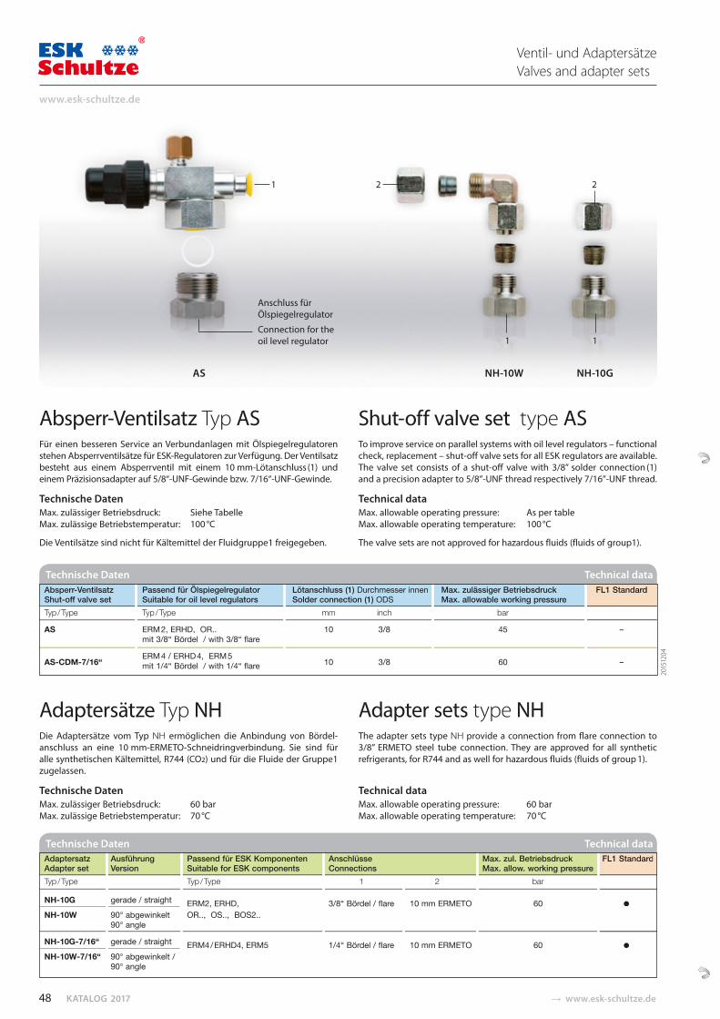
KATALOG 2017 � www.esk-schultze.de
AS NH-10W NH-10G
1
Anschluss für Ölspiegelregulator
Connection for the oil level regulator
Absperr-Ventilsatz Typ AS Für einen besseren Service an Verbundanlagen mit Ölspiegelregulatoren stehen Absperrventilsätze für ESK-Regulatoren zur Verfü gung. Der Ventilsatz besteht aus einem Absperrventil mit einem 10 mm-Lötanschluss (1) und einem Präzisionsadapter auf 5/8“-UNF-Gewinde bzw. 7/16“-UNF-Gewinde.
Technische Daten Max. zulässiger Betriebsdruck: Siehe Tabelle Max. zulässige Betriebstemperatur: 100 °C
Die Ventilsätze sind nicht für Kältemittel der Fluidgruppe1 freigegeben.
Shut-off valve set type AS To improve service on parallel systems with oil level regulators – functional check, replacement – shut-off valve sets for all ESK regulators are available. The valve set consists of a shut-off valve with 3/8” solder connection (1) and a precision adapter to 5/8”-UNF thread respectively 7/16”-UNF thread.
Technical data Max. allowable operating pressure: As per table Max. allowable operating temperature: 100 °C
The valve sets are not approved for hazardous fluids (fluids of group1).
Ventil- und AdaptersätzeValves and adapter sets
Technische Daten Technical data Absperr-Ventilsatz Passend für Ölspiegelregulator Lötanschluss (1) Durchmesser innen Max. zulässiger Betriebsdruck FL1 Standard Shut-off valve set Suitable for oil level regulators Solder connection (1) ODS Max. allowable working pressure Typ / Type Typ / Type mm inch bar
AS ERM 2, ERHD, OR.. 10 3/8 45 – mit 3/8“ Bördel / with 3/8“ flare
AS-CDM-7/16“
ERM 4 / ERHD 4, ERM 5 10
3/8 60 – mit 1/4“ Bördel / with 1/4“ flare
FL1 Standard
–
–
Adaptersätze Typ NH Die Adaptersätze vom Typ NH ermöglichen die Anbindung von Bördel-anschluss an eine 10 mm-ERMETO-Schneidringverbindung. Sie sind für alle synthetischen Kältemittel, R744 (CO2) und für die Fluide der Gruppe1 zugelassen.
Technische Daten Max. zulässiger Betriebsdruck: 60 bar Max. zulässige Betriebstemperatur: 70 °C
Adapter sets type NH The adapter sets type NH provide a connection from flare connection to 3/8” ERMETO steel tube connection. They are approved for all synthetic refrigerants, for R744 and as well for hazardous fluids (fluids of group 1).
Technical data Max. allowable operating pressure: 60 bar Max. allowable operating temperature: 70 °C
Technische Daten Technical data Adaptersatz Ausführung Passend für ESK Komponenten Anschlüsse Max. zul. Betriebsdruck FL1 Standard Adapter set Version Suitable for ESK components Connections Max. allow. working pressure Typ / Type Typ / Type 1 2 bar
NH-10G gerade / straight ERM2, ERHD, 3/8“ Bördel / flare 10 mm ERMETO 60 ●
NH-10W 90° abgewinkelt OR.., OS.., BOS2.. 90° angle
NH-10G-7/16“ gerade / straight ERM4 / ERHD4, ERM5 1/4“ Bördel / flare 10 mm ERMETO 60 ●
NH-10W-7/16“ 90° abgewinkelt / 90° angle
FL1 Standard
●
1
2 2
1
2015
1204
48
www.esk-schultze.de
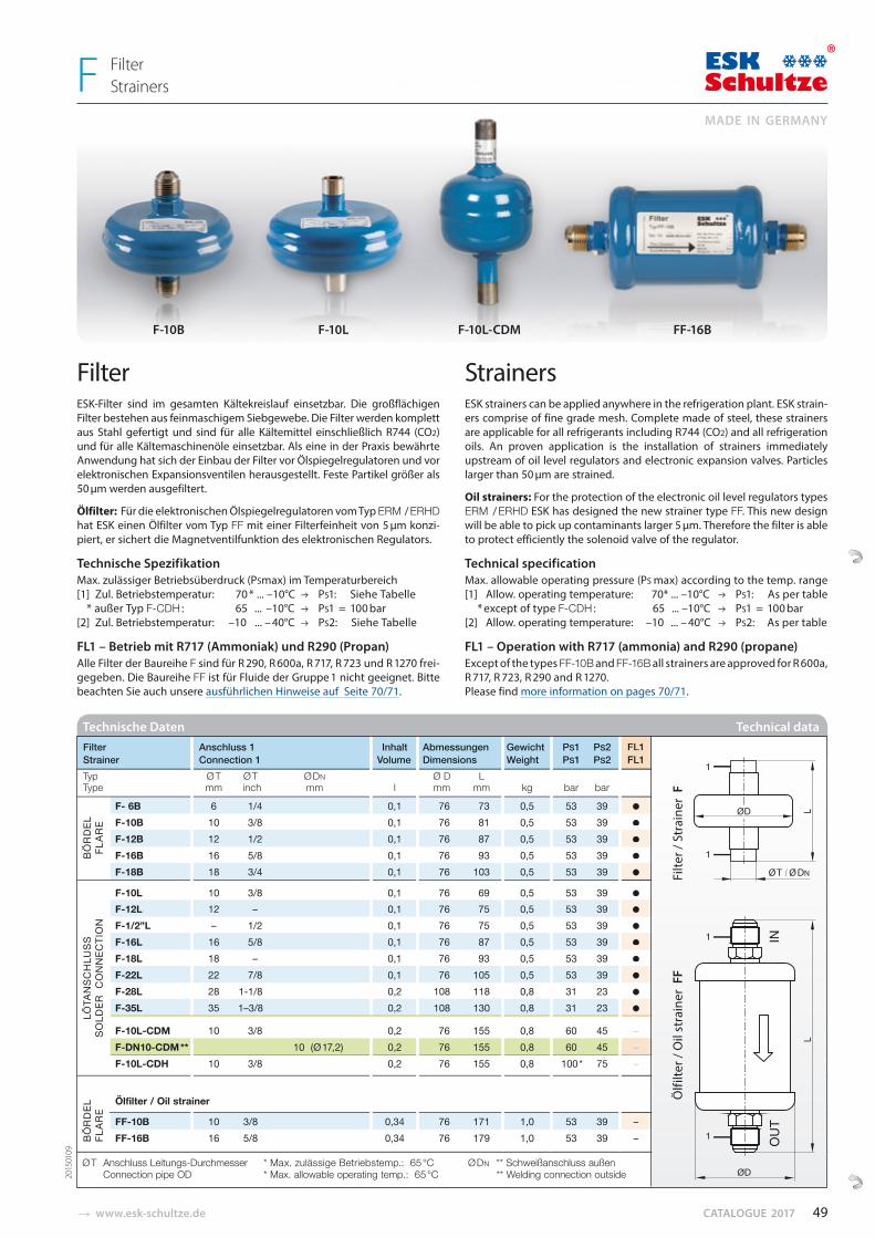
� www.esk-schultze.de CATALOGUE 2017
F-10B F-10L F-10L-CDM FF-16B
Technische Daten Technical data
Filter Anschluss 1 Inhalt Abmessungen Gewicht PS1 PS2 FL1 Strainer Connection 1 Volume Dimensions Weight PS1 PS2 FL1 Typ Ø T Ø T Ø DN Ø D L Type mm inch mm l mm mm kg bar bar
F- 6B 6 1/4 0,1 76 73 0,5 53 39 ●
F-10B 10 3/8 0,1 76 81 0,5 53 39 ●
F-12B 12 1/2 0,1 76 87 0,5 53 39 ●
F-16B 16 5/8 0,1 76 93 0,5 53 39 ●
F-18B 18 3/4 0,1 76 103 0,5 53 39 ●
F-10L 10 3/8 0,1 76 69 0,5 53 39 ●
F-12L 12 – 0,1 76 75 0,5 53 39 ●
F-1/2”L – 1/2 0,1 76 75 0,5 53 39 ●
F-16L 16 5/8 0,1 76 87 0,5 53 39 ●
F-18L 18 – 0,1 76 93 0,5 53 39 ●
F-22L 22 7/8 0,1 76 105 0,5 53 39 ●
F-28L 28 1-1/8 0,2 108 118 0,8 31 23 ●
F-35L 35 1–3/8 0,2 108 130 0,8 31 23 ●
F-10L-CDM 10 3/8 0,2 76 155 0,8 60 45 –
F-DN10-CDM ** 10 (Ø 17,2) 0,2 76 155 0,8 60 45 –
F-10L-CDH 10 3/8 0,2 76 155 0,8 100 * 75 –
Ölfilter / Oil strainer
FF-10B 10 3/8 0,34 76 171 1,0 53 39 – FF-16B 16 5/8 0,34 76 179 1,0 53 39 –
––
–––
●
●
●
●
●
●
●
●
●
●
●
●
●
FL1FL1
FilterStrainers F
BÖ
RD
ELFL
ARE
LÖTA
NSC
HLU
SS
SOLD
ER C
ON
NEC
TIO
NB
ÖR
DEL
FLAR
E
Filter ESK-Filter sind im gesamten Kältekreislauf einsetzbar. Die großflächigen Filter bestehen aus feinmaschigem Siebge we be. Die Filter werden komplett aus Stahl gefertigt und sind für alle Kältemittel einschließlich R744 (CO2) und für alle Kälte maschi nen öle ein setzbar. Als eine in der Praxis bewährte Anwendung hat sich der Einbau der Filter vor Ölspiegelregulatoren und vor elektronischen Expansionsventilen herausgestellt. Feste Partikel größer als 50 μm werden ausgefiltert.
Ölfilter: Für die elektronischen Ölspiegelregulatoren vom Typ ERM / ERHD hat ESK einen Ölfilter vom Typ FF mit einer Filterfeinheit von 5 μm konzi-piert, er sichert die Mag netventilfunktion des elektronischen Re gu lators.
Technische Spezifikation Max. zulässiger Betriebsüberdruck (PSmax) im Temperaturbereich[1] Zul. Betriebstemperatur: 70 * ... –10°C PS1: Siehe Tabelle * außer Typ F-CDH : 65 ... –10°C PS1 = 100 bar [2] Zul. Betriebstemperatur: –10 ... – 40°C PS2: Siehe Tabelle
FL1 – Betrieb mit R717 (Ammoniak) und R290 (Propan)Alle Filter der Baureihe F sind für R 290, R 600a, R 717, R 723 und R 1270 frei-gegeben. Die Baureihe FF ist für Fluide der Gruppe 1 nicht geeignet. Bitte beachten Sie auch unsere ausführlichen Hinweise auf Seite 70/71.
Strainers ESK strainers can be applied anywhere in the refrigeration plant. ESK strain-ers comprise of fine grade mesh. Complete made of steel, these strainers are applicable for all refrigerants including R744 (CO2) and all refrigeration oils. An proven application is the installation of strainers immediately upstream of oil level regulators and electronic expansion valves. Particles larger than 50 μm are strained.
Oil strainers: For the protection of the electronic oil level regulators types ERM / ERHD ESK has designed the new strainer type FF. This new design will be able to pick up contaminants larger 5 μm. Therefore the filter is able to protect efficiently the solenoid valve of the regulator.
Technical specification Max. allowable operating pressure (PS max) according to the temp. range[1] Allow. operating temperature: 70* ... –10°C PS1: As per table * except of type F-CDH : 65 ... –10°C PS1 = 100 bar [2] Allow. operating temperature: –10 ... – 40°C PS2: As per table
FL1 – Operation with R717 (ammonia) and R290 (propane)Except of the types FF-10B and FF-16B all strainers are approved for R 600a, R 717, R 723, R 290 and R 1270. Please find more information on pages 70/71.
Ö
lfilte
r / O
il st
rain
er F
F
Filte
r / S
trai
ner
F
2015
0109
Ø T Anschluss Leitungs-Durchmesser * Max. zulässige Betriebstemp.: 65 °C Ø DN ** Schweißanschluss außen Connection pipe OD * Max. allowable operating temp.: 65 °C ** Welding connection outside
49
MADE IN GERMANY
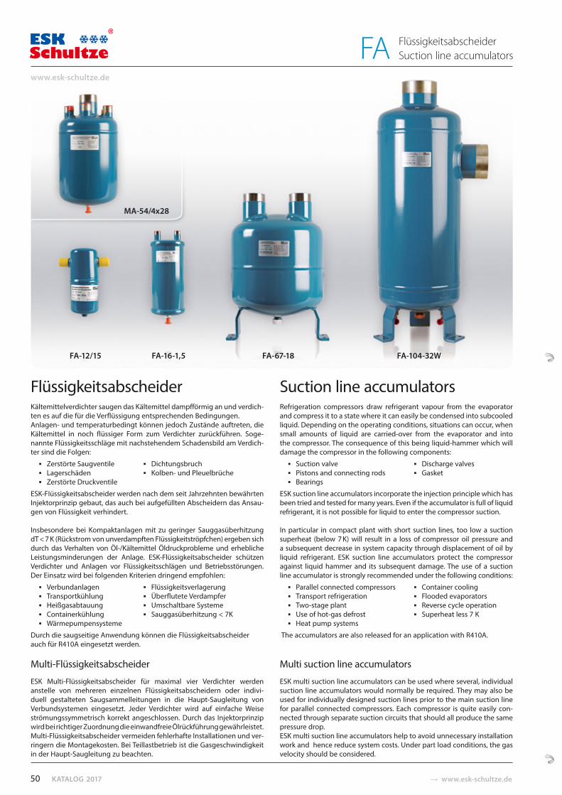
KATALOG 2017 � www.esk-schultze.de
FA-12/15 FA-16-1,5 FA-67-18 FA-104-32W
FlüssigkeitsabscheiderKältemittelverdichter saugen das Kälte mittel dampf förmig an und verdich-ten es auf die für die Verflüssigung entsprechenden Bedin gungen.Anlagen- und temperaturbedingt können jedoch Zustände auftreten, die Kältemittel in noch flüssiger Form zum Ver dich ter zurückführen. Soge-nannte Flüssigkeitsschläge mit nachstehendem Schadensbild am Verdich-ter sind die Folgen:
Zerstörte Saugventile Dichtungsbruch Lagerschäden Kolben- und Pleuelbrüche Zerstörte Druckventile
ESK-FIüssigkeitsabscheider werden nach dem seit Jahrzehnten bewährten Injektorprinzip gebaut, das auch bei aufgefüllten Abscheidern das Ansau-gen von Flüssigkeit verhindert.
Insbesondere bei Kompaktanlagen mit zu geringer Sauggasüberhitzung dT < 7 K (Rück strom von unverdampften FIüssigkeitströpfchen) ergeben sich durch das Verhalten von Öl-/Kältemittel Öldruckprobleme und erhebliche Leistungs minderungen der Anlage. ESK-Flüssigkeitsabscheider schützen Verdichter und Anlagen vor Flüssigkeitsschlägen und Betriebsstörungen. Der Einsatz wird bei folgenden Kriterien dringend empfohlen:
Verbundanlagen Flüssigkeitsverlagerung Transportkühlung Überflutete Verdampfer Heißgasabtauung Umschaltbare Systeme Containerkühlung Sauggasüberhitzung < 7K Wärmepumpensysteme
Durch die saugseitige Anwendung können die Flüssigkeitsabscheider auch für R410A eingesetzt werden.
Multi-Flüssigkeitsabscheider
ESK Multi-Flüssigkeitsabscheider für maximal vier Verdichter werden an stel le von mehreren einzelnen Flüssigkeitsabscheidern oder indivi-duell gestal teten Saugsammellei tungen in die Haupt-Saugleitung von Ver bundsystemen ein gesetzt. Jeder Verdichter wird auf einfache Weise strömungs sym me trisch korrekt angeschlossen. Durch das Injektor prinzip wird bei richtiger Zuordnung die einwandfreie Ölrückführung gewährleistet. Multi-Flüssig keitsabscheider vermeiden fehlerhafte Installationen und ver-ringern die Montage kosten. Bei Teillastbetrieb ist die Gasgeschwin digkeit in der Haupt -Saugleitung zu beachten.
Suction line accumulatorsRefrigeration compressors draw refrigerant vapour from the evaporator and compress it to a state where it can easily be condensed into subcooled liquid. Depending on the operating conditions, situations can occur, when small amounts of liquid are carried-over from the evaporator and into the compressor. The consequence of this being liquid-hammer which will damage the compressor in the following components:
Suction valve Discharge valves Pistons and connecting rods Gasket Bearings
ESK suction line accumulators incorporate the injection principle which has been tried and tested for many years. Even if the accumulator is full of liquid refrigerant, it is not possible for liquid to enter the compressor suction.
In particular in compact plant with short suction lines, too low a suc tion superheat (below 7 K) will result in a loss of compressor oil pressure and a subsequent decrease in system capacity through displacement of oil by liquid refrigerant. ESK suction line accumulators protect the compressor against liquid hammer and its subsequent damage. The use of a suction line accu mulator is strongly recommended under the following conditions:
Parallel connected compressors Container cooling Transport refrigeration Flooded evaporators Two-stage plant Reverse cycle operation Use of hot-gas defrost Superheat less 7 K Heat pump systems
The accumulators are also released for an application with R410A.
Multi suction line accumulators
ESK multi suction line accumulators can be used where several, individual suction line accumulators would normally be required. They may also be used for individually designed suction lines prior to the main suction line for parallel connected compressors. Each compressor is quite easily con-nected through separate suction circuits that should all produce the same pressure drop. ESK multi suction line accumulators help to avoid unnecessary installation work and hence reduce system costs. Under part load conditions, the gas velocity should be considered.
MA-54/4x28
50
www.esk-schultze.de
FlüssigkeitsabscheiderSuction line accumulatorsFA
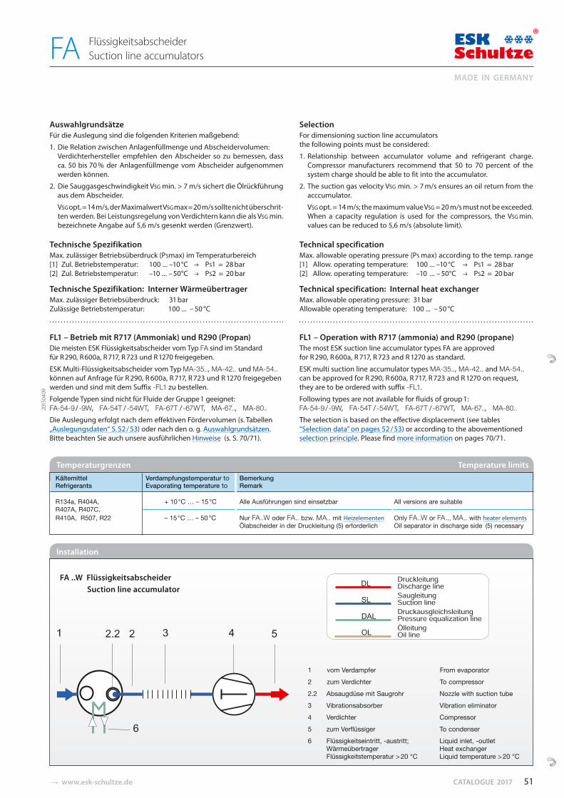
� www.esk-schultze.de CATALOGUE 2017
AuswahlgrundsätzeFür die Auslegung sind die folgenden Kriterien maßgebend:
1. Die Relation zwischen Anlagenfüllmenge und Ab scheidervolumen: Verdichterhersteller empfehlen den Abscheider so zu bemessen, dass ca. 50 bis 70 % der Anlagenfüllmenge vom Abscheider aufgenommen werden können.
2. Die Sauggasgeschwindigkeit VSG min. > 7 m/s sichert die Ölrückfüh rung aus dem Abscheider.
VSG opt. = 14 m/s, der Maximalwert VSG max = 20 m/s sollte nicht überschrit-ten werden. Bei Lei stungsregelung von Verdichtern kann die als VSG min. bezeichnete Angabe auf 5,6 m/s gesenkt werden (Grenzwert).
Technische Spezifikation Max. zulässiger Betriebsüberdruck (PSmax) im Temperaturbereich[1] Zul. Betriebstemperatur: 100 ... –10 °C PS1 = 28 bar[2] Zul. Betriebstemperatur: –10 ... – 50°C PS2 = 20 bar
Technische Spezifikation: Interner Wärmeübertrager Max. zulässiger Betriebsüberdruck: 31 barZulässige Betriebstemperatur: 100 ... – 50 °C
FL1 – Betrieb mit R717 (Ammoniak) und R290 (Propan)Die meisten ESK Flüssigkeitsabscheider vom Typ FA sind im Standard für R 290, R 600a, R 717, R 723 und R 1270 freigegeben.
ESK Multi-Flüssigkeitsabscheider vom Typ MA-35.., MA-42.. und MA-54.. können auf Anfrage für R 290, R 600a, R 717, R 723 und R 1270 freigegeben werden und sind mit dem Suffix -FL1 zu bestellen.
Folgende Typen sind nicht für Fluide der Gruppe 1 geeignet: FA-54-9 / -9W, FA-54T / -54WT, FA-67T / -67WT, MA-67.., MA-80..Die Auslegung erfolgt nach dem effektiven Fördervolumen (s. Tabellen „Auslegungsdaten“ S. 52 / 53) oder nach den o. g. Auswahlgrundsätzen. Bitte beachten Sie auch unsere ausführlichen Hinweise (s. S. 70/71).
SelectionFor dimensioning suction line accumulators the fol low ing points must be consi dered:
1. Relationship between accumulator volume and refrigerant charge. Compressor manufacturers recommend that 50 to 70 percent of the system charge should be able to fit into the accumulator.
2. The suction gas velocity VSG min. > 7 m/s ensures an oil return from the acccumulator.
VSG opt. = 14 m/s; the maximum value VSG = 20 m/s must not be exceeded. When a capacity regulation is used for the compressors, the VSG min. values can be reduced to 5,6 m/s (absolute limit).
Technical specification Max. allowable operating pressure (PS max) according to the temp. range[1] Allow. operating temperature: 100 ... –10 °C PS1 = 28 bar [2] Allow. operating temperature: –10 ... – 50°C PS2 = 20 bar
Technical specification: Internal heat exchangerMax. allowable operating pressure: 31 barAllowable operating temperature: 100 ... – 50 °C
FL1 – Operation with R717 (ammonia) and R290 (propane)The most ESK suction line accumulator types FA are approved for R 290, R 600a, R 717, R 723 and R 1270 as standard.
ESK multi suction line accumulator types MA-35.., MA-42.. and MA-54.. can be approved for R 290, R 600a, R 717, R 723 and R 1270 on request,they are to be ordered with suffix -FL1.
Following types are not available for fluids of group 1: FA-54-9 / -9W, FA-54T / -54WT, FA-67T / -67WT, MA-67.., MA-80..The selection is based on the effective displacement (see tables “Selection data” on pages 52 / 53) or according to the abovementioned selection principle. Please find more information on pages 70/71.
Kältemittel Verdampfungstemperatur to Bemerkung Refrigerants Evaporating temperature to Remark
R134a, R404A, + 10 °C … – 15 °C Alle Ausführungen sind einsetzbar All versions are suitable R407A, R407C, R410A, R507, R22 – 15 °C … – 50 °C Nur FA..W oder FA.. bzw. MA.. mit Heizelementen Only FA..W or FA.., MA.. with heater elements Ölabscheider in der Druckleitung (5) erforderlich Oil separator in discharge side (5) necessary
Temperaturgrenzen Temperature limits
Installation
1 vom Verdampfer From evaporator2 zum Verdichter To compressor2.2 Absaugdüse mit Saugrohr Nozzle with suction tube3 Vibrationsabsorber Vibration eliminator4 Verdichter Compressor5 zum Verflüssiger To condenser6 Flüssigkeitseintritt, -austritt; Liquid inlet, -outlet Wärmeübertrager Heat exchanger Flüssigkeitstemperatur > 20 °C Liquid temperature > 20 °C
FA ..W Flüssigkeitsabscheider Suction line accumulator
2015
0409
51
MADE IN GERMANY
FlüssigkeitsabscheiderSuction line accumulatorsFA
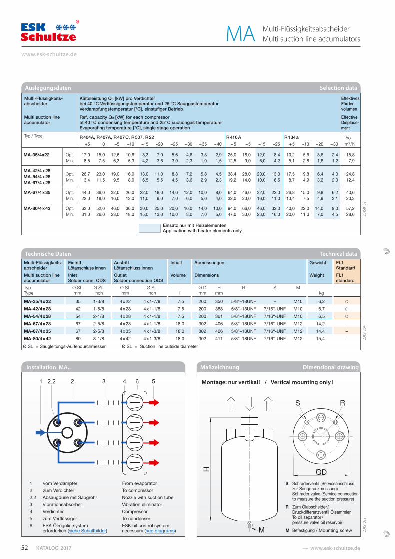
KATALOG 2017 � www.esk-schultze.de
Installation MA..
1 vom Verdampfer From evaporator2 zum Verdichter To compressor2.2 Absaugdüse mit Saugrohr Nozzle with suction tube3 Vibrationsabsorber Vibration eliminator4 Verdichter Compressor5 zum Verflüssiger To condenser6 ESK Ölreguliersystem ESK oil control system erforderlich (siehe Schaltbilder) necessary (see diagrams)
Auslegungsdaten Selection data
Maßzeichnung Dimensional drawing
Multi-Flüssigkeits- Kälteleistung Q0 [kW] pro Verdichter Effektives abscheider bei 40 °C Verflüssigungstemperatur und 25 °C Sauggastemperatur Förder- Verdampfungstemperatur [°C], einstufiger Betrieb volumen
Multi suction line Ref. capacity Q0 [kW] for each compressor Effective accumulator at 40 °C condensing temperature and 25 °C suctiongas temperature Displace- Evaporating temperature [°C], single stage operation ment
Typ / Type R 404A, R 407A, R 407 C, R 507, R 22 R 410 A R 134 a Vo +5 0 –5 –10 –15 –20 –25 – 30 – 35 – 40 + 5 – 5 –15 –25 + 5 –10 – 20 – 30 m³ / h
MA-35/4x22 Opt. 17,0 15,0 12,6 10,6 8,3 7,0 5,6 4,6 3,8 2,9 25,0 18,0 12,0 8,4 10,2 5,6 3,6 2,4 15,8 Min. 8,5 7,5 6,3 5,3 4,2 3,6 3,0 2,3 1,9 1,5 12,5 9,0 6,0 4,2 5,1 2,8 1,8 1,2 7,9
MA-42/4 x 28 Opt. 26,7 23,0 19,0 16,0 13,0 11,0 8,8 7,2 5,8 4,5 38,4 28,0 20,0 13,0 17,5 9,8 6,4 4,0 24,8 MA-54/4 x 28 Min. 13,4 11,5 9,5 8,0 6,5 5,5 4,5 3,6 2,9 2,3 19,2 14,0 10,0 6,5 8,7 4,9 3,2 2,0 12,4 MA-67/4 x 28
MA-67/4 x 35 Opt. 44,0 36,0 32,0 26,0 22,0 18,0 14,0 12,0 10,0 8,0 64,0 46,0 32,0 22,0 26,8 15,0 9,8 6,2 40,6 Min. 22,0 18,0 16,0 13,0 11,0 9,0 7,0 6,0 5,0 4,0 32,0 23,0 16,0 11,0 13,4 7,5 4,9 3,1 20,3
MA-80/4 x 42 Opt. 62,0 52,0 46,0 36,0 30,0 25,0 20,0 16,0 14,0 10,0 94,0 66,0 46,0 32,0 40,0 22,0 14,0 9,0 57,2 Min. 31,0 26,0 23,0 18,0 15,0 13,0 10,0 8,0 7,0 5,0 47,0 33,0 23,0 16,0 20,0 11,0 7,0 4,5 28,6
Einsatz nur mit Heizelementen Application with heater elements only
2015
0109
Montage: nur vertikal ! / Vertical mounting only !
S: Schraderventil (Serviceanschluss zur Saugdruckmessung) Schrader valve (Service connection to measure the suction pressure)R Zum Ölabscheider / Druckdifferenzventil Ölsammler To oil separator / pressure valve oil reservoirM Befestigung / Mounting screw 20
1510
29
Multi-Flüssigkeits- Eintritt Austritt Inhalt Abmessungen Gewicht FL1 abscheider Lötanschluss innen Lötanschluss innen Standard Multi suction line Inlet Outlet Volume Dimensions Weight FL1 accumulator Solder conn. ODS Solder connection ODS standard Typ Ø SL Ø SL Ø SL Ø SL Ø D H R S M Type mm inch mm inch l mm mm kg
MA-35/4 x 22 35 1-3/8 4 x 22 4 x 1-7/8 7,5 200 350 5/8”–18UNF – M10 6,2 ○
MA-42/4 x 28 42 1-5/8 4 x 28 4 x 1-1/8 7,5 200 388 5/8”–18UNF 7/16“-UNF M10 6,7 ○
MA-54/4 x 28 54 2-1/8 4 x 28 4 x 1-1/8 7,5 200 361 5/8”–18UNF 7/16“-UNF M10 6,5 ○
MA-67/4 x 28 67 2-5/8 4 x 28 4 x 1-1/8 18,0 302 406 5/8”–18UNF 7/16“-UNF M12 14,2 –
MA-67/4 x 35 67 2-5/8 4 x 35 4 x 1-3/8 18,0 302 406 5/8”–18UNF 7/16“-UNF M12 14,4 –
MA-80/4 x 42 80 3-1/8 4 x 42 4 x 1-3/8 18,0 302 411 5/8”–18UNF 7/16“-UNF M12 15,4 –
Ø SL = Saugleitungs-Außendurchmesser Ø SL = Suction line outside diameter
Technische Daten Technical dataFL1StandardFL1standard
○
○
○
– – – 20
1512
04
52
www.esk-schultze.de
Multi-FlüssigkeitsabscheiderMulti suction line accumulatorsMA
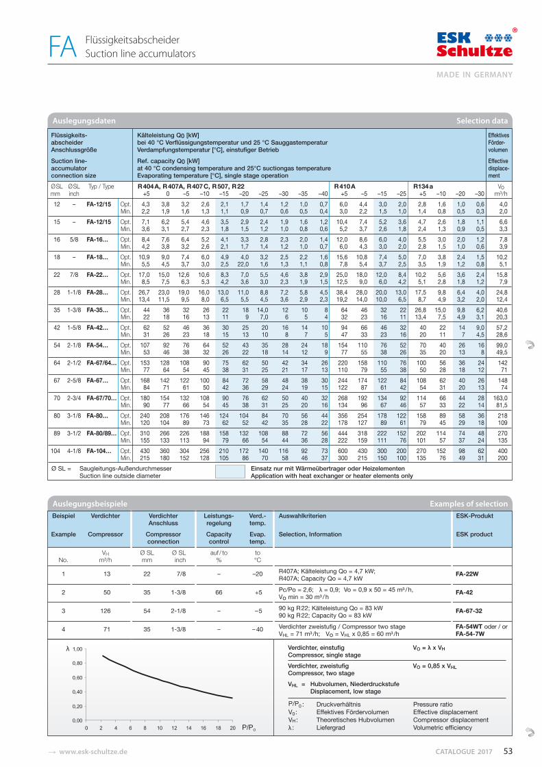
� www.esk-schultze.de CATALOGUE 2017
Auslegungsdaten Selection data
Flüssigkeits- Kälteleistung Q0 [kW] Effektives abscheider bei 40 °C Verflüssigungstemperatur und 25 °C Sauggastemperatur Förder- Anschlussgröße Verdampfungstemperatur [°C], einstufiger Betrieb volumen
Suction line- Ref. capacity Q0 [kW] Effective accumulator at 40 °C condensing temperature and 25°C suctiongas temperature displace- connection size Evaporating temperature [°C], single stage operation ment Ø SL Ø SL Typ / Type R 404 A, R 407A, R 407 C, R 507, R 22 R 410 A R134 a Vo mm inch +5 0 –5 –10 –15 –20 –25 –30 –35 –40 +5 –5 –15 –25 +5 –10 –20 –30 m³/h 12 – FA-12/15 Opt. 4,3 3,8 3,2 2,6 2,1 1,7 1,4 1,2 1,0 0,7 6,0 4,4 3,0 2,0 2,8 1,6 1,0 0,6 4,0 Min. 2,2 1,9 1,6 1,3 1,1 0,9 0,7 0,6 0,5 0,4 3,0 2,2 1,5 1,0 1,4 0,8 0,5 0,3 2,0 15 – FA-12/15 Opt. 7,1 6,2 5,4 4,6 3,5 2,9 2,4 1,9 1,6 1,2 10,4 7,4 5,2 3,6 4,7 2,6 1,8 1,1 6,6 Min. 3,6 3,1 2,7 2,3 1,8 1,5 1,2 1,0 0,8 0,6 5,2 3,7 2,6 1,8 2,4 1,3 0,9 0,5 3,3 16 5/8 FA-16… Opt. 8,4 7,6 6,4 5,2 4,1 3,3 2,8 2,3 2,0 1,4 12,0 8,6 6,0 4,0 5,5 3,0 2,0 1,2 7,8 Min. 4,2 3,8 3,2 2,6 2,1 1,7 1,4 1,2 1,0 0,7 6,0 4,3 3,0 2,0 2,8 1,5 1,0 0,6 3,9 18 – FA-18… Opt. 10,9 9,0 7,4 6,0 4,9 4,0 3,2 2,5 2,2 1,6 15,6 10,8 7,4 5,0 7,0 3,8 2,4 1,5 10,2 Min. 5,5 4,5 3,7 3,0 2,5 22,0 1,6 1,3 1,1 0,8 7,8 5,4 3,7 2,5 3,5 1,9 1,2 0,8 5,1 22 7/8 FA-22… Opt. 17,0 15,0 12,6 10,6 8,3 7,0 5,5 4,6 3,8 2,9 25,0 18,0 12,0 8,4 10,2 5,6 3,6 2,4 15,8 Min. 8,5 7,5 6,3 5,3 4,2 3,6 3,0 2,3 1,9 1,5 12,5 9,0 6,0 4,2 5,1 2,8 1,8 1,2 7,9 28 1-1/8 FA-28… Opt. 26,7 23,0 19,0 16,0 13,0 11,0 8,8 7,2 5,8 4,5 38,4 28,0 20,0 13,0 17,5 9,8 6,4 4,0 24,8 Min. 13,4 11,5 9,5 8,0 6,5 5,5 4,5 3,6 2,9 2,3 19,2 14,0 10,0 6,5 8,7 4,9 3,2 2,0 12,4 35 1-3/8 FA-35… Opt. 44 36 32 26 22 18 14,0 12 10 8 64 46 32 22 26,8 15,0 9,8 6,2 40,6 Min. 22 18 16 13 11 9 7,0 6 5 4 32 23 16 11 13,4 7,5 4,9 3,1 20,3 42 1-5/8 FA-42… Opt. 62 52 46 36 30 25 20 16 14 10 94 66 46 32 40 22 14 9,0 57,2 Min. 31 26 23 18 15 13 10 8 7 5 47 33 23 16 20 11 7 4,5 28,6 54 2-1/8 FA-54… Opt. 107 92 76 64 52 43 35 28 24 18 154 110 76 52 70 40 26 16 99,0 Min. 53 46 38 32 26 22 18 14 12 9 77 55 38 26 35 20 13 8 49,5 64 2-1/2 FA-67/64… Opt. 153 128 108 90 75 62 50 42 34 26 220 158 110 76 100 56 36 24 142 Min. 77 64 54 45 38 31 25 21 17 13 110 79 55 38 50 28 18 12 71 67 2-5/8 FA-67… Opt. 168 142 122 100 84 72 58 48 38 30 244 174 122 84 108 62 40 26 148 Min. 84 71 61 50 42 36 29 24 19 15 122 87 61 42 54 31 20 13 74 70 2-3/4 FA-67/70… Opt. 180 154 132 108 90 76 62 50 40 32 268 192 134 92 114 66 44 28 163,0 Min. 90 77 66 54 45 38 31 25 20 16 134 96 67 46 57 33 22 14 81,5 80 3-1/8 FA-80… Opt. 240 208 176 146 124 104 84 70 56 44 356 254 178 122 158 89 58 36 218 Min. 120 104 89 73 62 52 42 35 28 22 178 127 89 61 79 45 29 18 109 89 3-1/2 FA-80/89… Opt. 310 266 226 188 158 132 108 88 72 56 444 318 222 152 202 114 74 48 270 Min. 155 133 113 94 79 66 54 44 36 28 222 159 111 76 101 57 37 24 135 104 4-1/8 FA-104… Opt. 430 360 304 256 210 172 140 116 92 73 600 430 300 200 270 152 98 62 400 Min. 215 180 152 128 105 86 70 58 46 37 300 215 150 100 135 76 49 31 200
P/P0 : Druckverhältnis Pressure ratioV0 : Effektives Fördervolumen Effective displacementVH : Theoretisches Hubvolumen Compressor displacementλ : Liefergrad Volumetric efficiency
Verdichter, einstufig VO = λ x VHCompressor, single stageVerdichter, zweistufig VO = 0,85 x VHLCompressor, two stageVHL = Hubvolumen, Niederdruckstufe Displacement, low stage
Beispiel Verdichter Verdichter Leistungs- Verd.- Auswahlkriterien ESK-Produkt Anschluss regelung temp.
Example Compressor Compressor Capacity Evap. Selection, Information ESK product connection control temp.
VH Ø SL Ø SL auf / to to No. m³/h mm inch % °C
1 13 22 7/8 – –20 R407A; Kälteleistung Qo = 4,7 kW; R407A; Capacity Qo = 4,7 kW
FA-22W
2 50 35 1-3/8 66 +5 Pc/Po = 2,6; λ = 0,9; Vo = 0,9 x 50 = 45 m³ / h, Vo min = 30 m³ / h
FA-42
3 126 54 2-1/8 – –5 90 kg R 22; Kälteleistung Qo = 83 kW 90 kg R 22; Capacity Qo = 83 kW
FA-67-32
4 71 35 1-3/8 – – 40 Verdichter zweistufig / Compressor two stage FA-54WT oder / or VHL = 71 m³ /h; Vo = VHL x 0,85 = 60 m³ /h FA-54-7W
Auslegungsbeispiele Examples of selection
Ø SL = Saugleitungs-Außendurchmesser Einsatz nur mit Wärmeübertrager oder Heizelementen Suction line outside diameter Application with heat exchanger or heater elements only
53
MADE IN GERMANY
FlüssigkeitsabscheiderSuction line accumulatorsFA
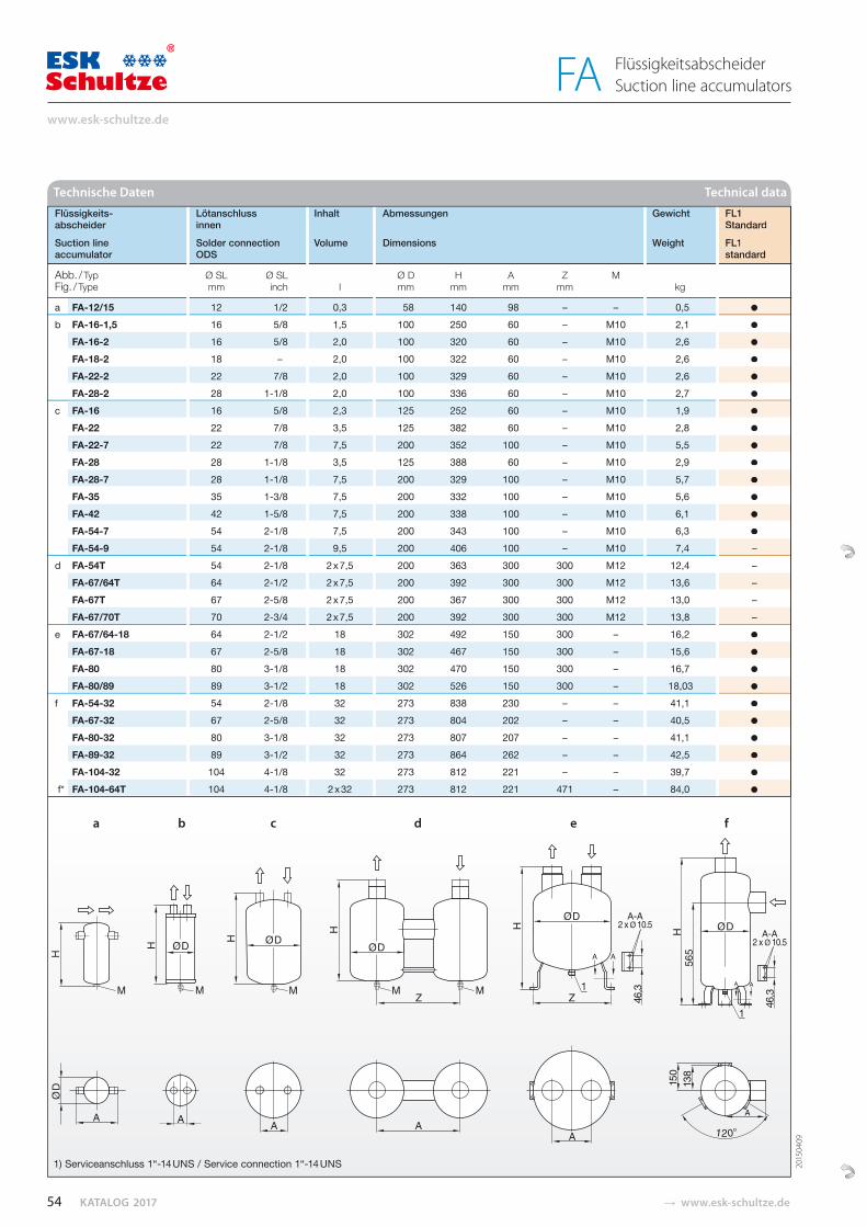
KATALOG 2017 � www.esk-schultze.de
Flüssigkeits- Lötanschluss Inhalt Abmessungen Gewicht FL1 abscheider innen Standard
Suction line Solder connection Volume Dimensions Weight FL1 accumulator ODS standard
Abb. / Typ Ø SL Ø SL Ø D H A Z M Fig. / Type mm inch l mm mm mm mm kg
a FA-12/15 12 1/2 0,3 58 140 98 – – 0,5 ●
b FA-16-1,5 16 5/8 1,5 100 250 60 – M10 2,1 ●
FA-16-2 16 5/8 2,0 100 320 60 – M10 2,6 ●
FA-18-2 18 – 2,0 100 322 60 – M10 2,6 ●
FA-22-2 22 7/8 2,0 100 329 60 – M10 2,6 ●
FA-28-2 28 1-1/8 2,0 100 336 60 – M10 2,7 ●
c FA-16 16 5/8 2,3 125 252 60 – M10 1,9 ●
FA-22 22 7/8 3,5 125 382 60 – M10 2,8 ●
FA-22-7 22 7/8 7,5 200 352 100 – M10 5,5 ●
FA-28 28 1-1/8 3,5 125 388 60 – M10 2,9 ●
FA-28-7 28 1-1/8 7,5 200 329 100 – M10 5,7 ● FA-35 35 1-3/8 7,5 200 332 100 – M10 5,6 ●
FA-42 42 1-5/8 7,5 200 338 100 – M10 6,1 ●
FA-54-7 54 2-1/8 7,5 200 343 100 – M10 6,3 ●
FA-54-9 54 2-1/8 9,5 200 406 100 – M10 7,4 – d FA-54T 54 2-1/8 2 x 7,5 200 363 300 300 M12 12,4 – FA-67/64T 64 2-1/2 2 x 7,5 200 392 300 300 M12 13,6 – FA-67T 67 2-5/8 2 x 7,5 200 367 300 300 M12 13,0 – FA-67/70T 70 2-3/4 2 x 7,5 200 392 300 300 M12 13,8 – e FA-67/64-18 64 2-1/2 18 302 492 150 300 – 16,2 ●
FA-67-18 67 2-5/8 18 302 467 150 300 – 15,6 ●
FA-80 80 3-1/8 18 302 470 150 300 – 16,7 ●
FA-80/89 89 3-1/2 18 302 526 150 300 – 18,03 ●
f FA-54-32 54 2-1/8 32 273 838 230 – – 41,1 ●
FA-67-32 67 2-5/8 32 273 804 202 – – 40,5 ●
FA-80-32 80 3-1/8 32 273 807 207 – – 41,1 ●
FA-89-32 89 3-1/2 32 273 864 262 – – 42,5 ●
FA-104-32 104 4-1/8 32 273 812 221 – – 39,7 ●
f* FA-104-64T 104 4-1/8 2 x 32 273 812 221 471 – 84,0 ●
Technische Daten Technical data
FL1 Standard
FL1standard
●
●
●
●
●
●
●
●
●
●
●
●
●
●
– – – – –
●
●
●
●
●
●
●
●
●
●
1) Serviceanschluss 1“-14 UNS / Service connection 1“-14 UNS
a b c d e f
2015
0409
54
www.esk-schultze.de
FlüssigkeitsabscheiderSuction line accumulatorsFA

� www.esk-schultze.de CATALOGUE 2017
Flüssigkeits- Lötanschluss Inhalt Lötanschluss Abmessungen Gewicht FL1 abscheider Innen Wärmeübertrager Standard
Suction line Solder connection Volume Solder connection Dimensions Weight FL1 accumulator ODS heat exchanger standard
Abb. / Typ Ø SL Ø SL Ø FL Ø FL Ø D H A W Z M Fig. / Type mm inch l mm inch mm mm mm mm mm kg
a FA-16W 16 5/8 2,3 16 5/8 125 261 60 80 – M10 2,4 ●
FA-22W 22 7/8 3,5 16 5/8 125 383 60 80 – M10 3,1 ●
FA-28W 28 1-1/8 3,5 16 5/8 125 388 60 80 – M10 3,5 ●
FA-35W 35 1-3/8 7,5 22 7/8 200 335 100 140 – M10 7,1 ●
FA-42W 42 1-5/8 7,5 22 7/8 200 339 100 140 – M10 7,3 ●
FA-54-7W 54 2-1/8 7,5 22 7/8 200 343 100 140 – M10 7,6 ● FA-54-9W 54 2-1/8 9,5 22 7/8 200 406 100 140 – M10 8,7 – b FA-54WT 54 2-1/8 2 x 7,5 22 7/8 200 363 300 140 300 M12 13,6 – FA-67/64WT 64 2-1/2 2 x 7,5 22 7/8 200 392 300 140 300 M12 14,9 – FA-67WT 67 2-5/8 2 x 7,5 22 7/8 200 367 300 140 300 M12 14,3 – c FA-67/64-18W 64 2-1/2 18 22 7/8 302 492 150 140 300 – 17,6 ●
FA-67-18W 67 2-5/8 18 22 7/8 302 467 150 140 300 – 17,0 ●
FA-80W 80 3-1/8 18 22 7/8 302 470 150 140 300 – 17,9 ●
FA-80/89W 89 3-1/2 18 22 7/8 302 526 150 140 300 – 19,2 ●
d FA-54-32W 54 2-1/8 32 16 5/8 273 838 231 174 – – 43,1 ●
FA-67-32W 67 2-5/8 32 16 5/8 273 804 202 174 – – 52,5 ●
FA-80-32W 80 3-1/8 32 16 5/8 273 807 207 174 – – 44,0 ●
FA-89-32W 89 3-1/2 32 16 5/8 273 864 262 174 – – 45,4 ●
FA-104-32W 104 4-1/8 32 16 5/8 273 812 221 174 – – 41,5 ●
d* FA-104-64WT 104 4-1/8 2 x 32 16 5/8 273 812 221 174 471 – 84,0 ●
Ø SL = Saugleitungs-Außendurchmesser Ø FL = Flüssigkeitsleitung * Aufbau und Abmessungen entsprechen dem Basisgerät FA-104-32/32W („Twin-Modell“) Ø SL = Suction line outside diameter Ø FL = Liquid line * Design and dimensions conform to the base model FA-104-32/32W (“twin-model“)
Technische Daten Technical data
a b c d
●
●
●
●
●
●
– – – –
●
●
●
●
●
●
●
●
●
FL1 Standard
FL1standard
1) Serviceanschluss 1“-14 UNS / Service connection 1“-14 UNS 2) Wärmeübertrager / Heat exchanger2015
1029
55
MADE IN GERMANY
Flüssigkeitsabscheider mit WärmeübertragerSuction line accumulators with heat exchangerFA
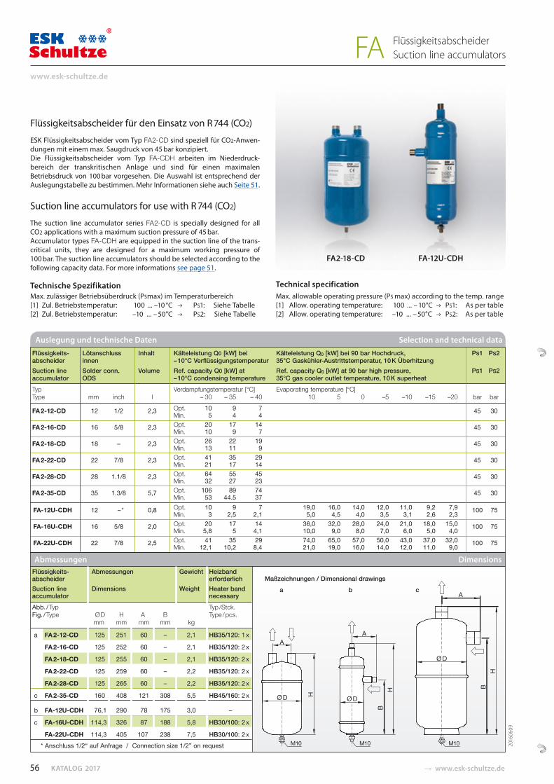
KATALOG 2017 � www.esk-schultze.de
Flüssigkeitsabscheider für den Einsatz von R 744 (CO2)
ESK Flüssigkeitsabscheider vom Typ FA2-CD sind spe ziell für CO2-Anwen-dungen mit einem max. Saugdruck von 45 bar konzipiert. Die Flüssigkeitsabscheider vom Typ FA-CDH arbeiten im Niederdruck-bereich der transkritischen Anlage und sind für einen maximalen Betriebsdruck von 100 bar vorgesehen. Die Auswahl ist entsprechend der Auslegungs ta belle zu bestimmen. Mehr Informationen siehe auch Seite 51.
Suction line accumulators for use with R 744 (CO2)
The suction line accumulator series FA2-CD is specially designed for all CO2 applications with a maximum suction pressure of 45 bar. Accumulator types FA-CDH are equipped in the suction line of the trans-critical units, they are designed for a maximum working pressure of 100 bar. The suction line accumulators should be selected according to the following capacity data. For more informations see page 51.
Technische Spezifikation Max. zulässiger Betriebsüberdruck (PSmax) im Temperaturbereich[1] Zul. Betriebstemperatur: 100 ... –10 °C PS1: Siehe Tabelle[2] Zul. Betriebstemperatur: –10 ... – 50°C PS2: Siehe Tabelle
Technical specification Max. allowable operating pressure (PS max) according to the temp. range[1] Allow. operating temperature: 100 ... – 10°C PS1: As per table[2] Allow. operating temperature: –10 ... – 50°C PS2: As per table
Auslegung und technische Daten Selection and technical data
Flüssigkeits- Lötanschluss Inhalt Kälteleistung Q0 [kW] bei Kälteleistung Q0 [kW] bei 90 bar Hochdruck, PS1 PS2 abscheider innen – 10°C Verflüssigungstemperatur 35°C Gaskühler-Austrittstemperatur, 10 K Überhitzung Suction line Solder conn. Volume Ref. capacity Q0 [kW] at Ref. capacity Q0 [kW] at 90 bar high pressure, PS1 PS2 accumulator ODS – 10°C condensing temperature 35°C gas cooler outlet temperature, 10 K superheat Typ Verdampfungstemperatur [°C] Evaporating temperature [°C] Type mm inch l – 30 – 35 – 40 10 5 0 –5 –10 –15 –20 bar bar
FA 2-12-CD 12 1/2 2,3 Opt. 10 9 7 45 30 Min. 5 4 4
FA 2-16-CD 16 5/8 2,3 Opt. 20 17 14 45 30 Min. 10 9 7 FA 2-18-CD 18 – 2,3 Opt. 26 22 19 45 30 Min. 13 11 9
FA 2-22-CD 22 7/8 2,3 Opt. 41 35 29 45 30 Min. 21 17 14
FA 2-28-CD 28 1.1/8 2,3 Opt. 64 55 45 45 30 Min. 32 27 23
FA 2-35-CD 35 1.3/8 5,7 Opt. 106 89 74 45 30 Min. 53 44.5 37
FA-12U-CDH 12 – * 0,8 Opt. 10 9 7 19,0 16,0 14,0 12,0 11,0 9,2 7,9 100 75 Min. 3 2,5 2,1 5,0 4,5 4,0 3,5 3,1 2,6 2,3 FA-16U-CDH 16 5/8 2,0 Opt. 20 17 14 36,0 32,0 28,0 24,0 21,0 18,0 15,0 100 75 Min. 5,8 5 4,1 10,0 9,0 8,0 7,0 6,0 5,0 4,0
FA-22U-CDH 22 7/8 2,5 Opt. 41 35 29 74,0 65,0 57,0 50,0 43,0 37,0 32,0 100 75 Min. 12,1 10,2 8,4 21,0 19,0 16,0 14,0 12,0 11,0 9,0 Abmessungen Dimensions
Maßzeichnungen / Dimensional drawings a b c
FA2-18-CD FA-12U-CDH
A
B
BH
H
H
M10M10M10
A
Ø D
Ø D
A
Ø D
Flüssigkeits- Abmessungen Gewicht Heizband abscheider erforderlich Suction line Dimensions Weight Heater band accumulator necessary Abb. / Typ Typ /Stck. Fig. / Type Ø D H A B Type / pcs. mm mm mm mm kg
a FA 2-12-CD 125 251 60 – 2,1 HB35/120: 1 x
FA 2-16-CD 125 252 60 – 2,1 HB35/120: 2 x
FA 2-18-CD 125 255 60 – 2,1 HB35/120: 2 x
FA 2-22-CD 125 259 60 – 2,2 HB35/120: 2 x
FA 2-28-CD 125 265 60 – 2,2 HB35/120: 2 x
c FA 2-35-CD 160 408 121 308 5,5 HB45/160: 2 x
b FA-12U-CDH 76,1 290 78 175 3,0 –
c FA-16U-CDH 114,3 326 87 188 5,8 HB30/100: 2 x
FA-22U-CDH 114,3 405 107 238 7,5 HB30/100: 2 x
* Anschluss 1/2“ auf Anfrage / Connection size 1/2” on request 2016
0609
56
www.esk-schultze.de
FlüssigkeitsabscheiderSuction line accumulatorsFA
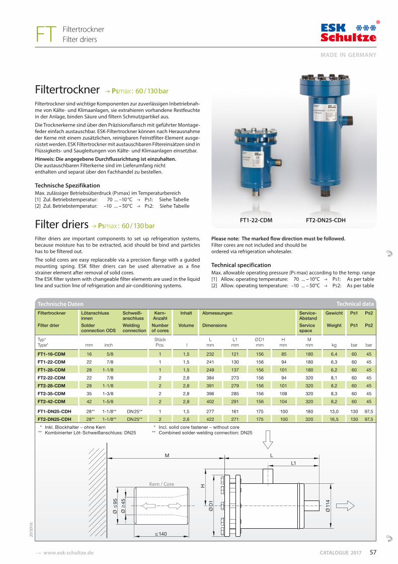
� www.esk-schultze.de CATALOGUE 2017
Filtertrockner PSmax : 60 / 130 bar
Filtertrockner sind wichtige Komponenten zur zuverlässigen Inbe triebnah-me von Kälte- und Klimaanlagen, sie extrahieren vorhandene Restfeuchte in der An lage, binden Säure und filtern Schmutz partikel aus.
Die Trocknerkerne sind über den Präzisionsflansch mit ge führter Montage-feder einfach austauschbar. ESK-Filter trock ner können nach Herausnahme der Kerne mit einem zusätzlichen, reinigbaren Feinstfilter-Element ausge-rüstet werden. ESK Filtertrockner mit austauschbaren Filtereinsätzen sind in Flüssigkeits- und Saugleitungen von Kälte- und Klimaanlagen einsetzbar.
Hinweis: Die angegebene Durchflussrichtung ist einzuhalten. Die austauschbaren Filterkerne sind im Lieferumfang nicht enthalten und separat über den Fachhandel zu bestellen. Technische Spezifikation Max. zulässiger Betriebsüberdruck (PSmax) im Temperaturbereich[1] Zul. Betriebstemperatur: 70 ... –10 °C PS1: Siehe Tabelle[2] Zul. Betriebstemperatur: –10 ... – 50°C PS2: Siehe Tabelle
Filter driers PSmax : 60 / 130 bar
Filter driers are important components to set up refrigeration systems, because moisture has to be extracted, acid should be bind and particles has to be filtered out.
The solid cores are easy replaceable via a precision flange with a guided mounting spring. ESK filter driers can be used alternative as a fine strainer element after removal of solid cores. The ESK filter system with changeable filter elements are used in the liquid line and suction line of refrigeration and air-conditioning systems.
Please note: The marked flow direction must be followed. Filter cores are not included and should be ordered via refrigeration wholesaler.
Technical specification Max. allowable operating pressure (PS max) according to the temp. range[1] Allow. operating temperature: 70 ... – 10°C PS1: As per table[2] Allow. operating temperature: –10 ... – 50°C PS2: As per table
Technische Daten Technical data
Filtertrockner Lötanschluss Schweiß- Kern- Inhalt Abmessungen Service- Gewicht PS1 PS2 innen anschluss Anzahl Abstand Filter drier Solder Welding Number Volume Dimensions Service Weight PS1 PS2 connection ODS connection of cores space
Typ* Stück L L1 Ø D1 H M Type* mm inch Pcs. l mm mm mm mm mm kg bar bar
FT1-16-CDM 16 5/8 1 1,5 232 121 156 85 180 6,4 60 45 FT1-22-CDM 22 7/8 1 1,5 241 130 156 94 180 6,3 60 45 FT1-28-CDM 28 1-1/8 1 1,5 249 137 156 101 180 6,2 60 45 FT2-22-CDM 22 7/8 2 2,8 384 273 156 94 320 8,1 60 45 FT2-28-CDM 28 1-1/8 2 2,8 391 279 156 101 320 8,2 60 45 FT2-35-CDM 35 1-3/8 2 2,8 396 285 156 108 320 8,3 60 45 FT2-42-CDM 42 1-5/8 2 2,8 402 291 156 104 320 8,2 60 45
FT1-DN25-CDH 28** 1-1/8** DN 25** 1 1,5 277 161 175 100 180 13,0 130 97,5 FT2-DN25-CDH 28** 1-1/8** DN 25** 2 2,6 422 271 175 100 320 16,5 130 97,5 * Inkl. Blockhalter – ohne Kern * Incl. solid core fastener – without core ** Kombinierter Löt- Schweißanschluss: DN25 ** Combined solder-welding connection: DN25
FT1-22-CDM FT2-DN25-CDH
2015
0116
57
MADE IN GERMANY
FiltertrocknerFilter driers FT
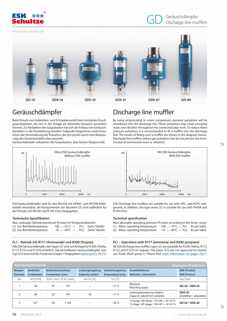
KATALOG 2017 � www.esk-schultze.de
GeräuschdämpferBeim Einsatz von Hubkolben- und Schraubenverdichtern entstehen Druck-gaspulsationen, die sich in der Anlage als störendes Geräusch auswirken können. Zur Reduktion der Gaspulsation hat sich der Einbau von Geräusch-dämpfern in die Druckleitung bewährt. Folgende Diagramme veranschau-lichen die Verminderung der Pulsation, die sich positiv durch eine Reduzie-rung des Gesamtschalldruckes auswirkt. Geräuschdämpfer reduzieren die Gaspulsation, aber keinen Körperschall.
Discharge line mufflerBy using reciprocating or screw compressors pressure pulsations will be introduced into the discharge line. These pulsations may cause annoying noise and vibration throughout the connected pipe work. To reduce these pressure pulsations it is recommended to fit a muffler into the discharge line. The results of fitting such a muffler are shown in the diagrams below.Discharge line mufflers reduce gas pulsations but do not prevent the trans-mission of mechanical noise or vibration.
Ohne ESK GeräuschdämpferWithout ESK muffler
Mit ESK GeräuschdämpferWith ESK muffler
GD-16 GDX-18 GDS-35 GDX-35 GDX-67 GD-80
ESK-Geräuschdämpfer sind für den Betrieb mit HFKW- und HFCKW-Kälte-mitteln einsetzbar, die Komponenten der Baureihe GD sind außerdem für den Einsatz mit R410A und R 744 (CO2) freigegeben.
Technische Spezifikation Max. zulässiger Betriebsüberdruck (PSmax) im Temperaturbereich[1] Zul. Betriebstemperatur: 140 ... –10 °C PS1: Siehe Tabelle[2] Zul. Betriebstemperatur: –10 ... – 40°C PS2: Siehe Tabelle
ESK Discharge line mufflers are suitable for use with HFC- and HCFC refri-gerants. In addition, the type series GD is suitable for use with R 410A and R 744 (CO2).
Technical specification Max. allowable operating pressure (PS max) according to the temp. range[1] Allow. operating temperature: 140 ... – 10°C PS1: As per table[2] Allow. operating temperature: –10 ... – 40°C PS2: As per table
FL1 – Betrieb mit R717 (Ammoniak) und R290 (Propan)Alle ESK Geräuschdämpfer des Types GD sind auf Anfrage für R 290, R 600a, R 717, R 723 und R 1270 erhältlich. Die einstellbaren Geräuschdämpfer vom Typ GDX sind nicht für Fluide der Gruppe 1 freigegeben (siehe auch S. 70/71).
FL1 – Operation with R717 (ammonia) and R290 (propane)All ESK discharge line mufflers type GD are available for R 290, R600a, R 717, R 723 and R 1270 on request. The types GDX are not approved for hazard-ous fluids (fluid group 1). Please find more information on pages 70/71.
Auslegungsbeispiele Examples of selection Beispiel Verdichter Verdichteranschluss Leistungsregelung Verdichtungstemp. Auswahlkriterien ESK-Produkt Example Compressor Compressor conn. Capacity control Evaporating temp. Selection, Information ESK-Product
No. VH [ m³/h] Ø DL [ mm ] Ø DL [ inch ] auf / to [ % ] to [ °C ] Typ / Type Bauraum 1 38 22 7/8 – – 5 °C Mounting space GD-22 / GDS-22
Leistungsanpassung möglich GDX-22 2 38 22 7/8 30 – 5 °C Capacity adjustment possible einstellbar / adjustable *2-stufig; HD-Stufe / VH HD = 42 m³ / h 3 127* 35 1-3/8 – – 40°C *2-stage; HP-stage / VH HP = 42 m³ / h GD-22 / GDS-22
58
www.esk-schultze.de
GeräuschdämpferDischarge line mufflersGD

� www.esk-schultze.de CATALOGUE 2017
Geräuschdämpfer, einstellbar
Die einstellbaren Geräuschdämpfer der Serie GDX eignen sich besonders für folgende Anwendungen:
Verdichter Verbundanlagen (zentrale Druckleitung) Schraubenverdichteranlagen leistungsgeregelte Verdichter individuelle Rohrleitungsführung große Verdampfungs-Temperaturbereiche (Kältemittelmassenstrom/Druckverhältnis) installierte Anlagen mit Geräuschproblemen
Durch die Einstellbarkeit auf der Ein- und/oder Austrittsseite ist bei den genannten Bedingungen eine optimale Beeinflussung der Pulsa tions-dämpfung erreichbar.
AuswahlgrundsätzeDie Anschlussgröße DL des Geräuschdämpfers sollte mit dem Drucklei-tungs querschnitt übereinstimmen, der nach kältetechnischen Regeln bestimmt wurde. Für den Einbau in Seriengeräte wird eine versuchstech-nische Erprobung empfohlen.
Für Seriengeräte können wir durch eine besondere Bauteilzuordnung (Lochblech-Typ, -Anzahl, -Abstände) problemlösende Sonderausführungen fertigen.
Discharge line muffler, adjustable
The adjustable discharge line mufflers of the GDX range are especially suitable for the following application:
Compressor parallel systems (central discharge line) Screw compressor systems Capacity controlled compressors Individual line arrangement Wide evaporating temperature ranges (ref. mass flow, pressure ratio) Fixed system with noise problems
In respect of the adjustement at the inlet- and/or outlet side, a high efficient influence of pulsation reduction is reachable.
SelectionThe connection size DL of the muffler should corres pond to the size of the discharge line, which has been selected according to the technical rules of refrigera tion. For equipment installation of discharge line mufflers labora-tory tests are recommended.
Special solutions for standard equipment manu facturer are possible by combination of baffle-type, -numbers and -distance.
Horizontale Installation GD.. / GDX.. Vertikale Installation GD.. / GDX..Horizontal installation Vertical installation
nicht empfohlennot recommended
empfohlen
recommended
1 Vibrationsabsorber 1 Vibration eliminator2 Abstützung 2 Support 3 Geräuschdämpfer 3 Discharge line muffler
Einstellung und Einbau der GDX-Geräte Adjusting and installation of the GDX-mufflers
GDX Horizontale Einbauposition Vor dem Einstellen Nach dem Einstellen Horizontal position of installation Before adjustment After adjustment
1 – Einstellspindel (GDX-67 2 x Eintrittsseite, GDX-16 / GDX-18 1x Eintrittsseite)2 – Schrader-Anschluss für Rohr Ø 6 mm3 – Einstelleinheit8 – Einbau horizontal, Druckanschluss - DL - unten
Einstellvorgang auf der Eintritts- und/oder Austrittsseite:A – Verschlusskappe (4) und Konterscheibe (5) lösen.B – Gasfluss drosseln (6) oder vergrößern (7).C – Druckabfall ist über die Schraderventile (2) messbar.D – Konterscheibe (5) einsetzen und die Einstellung sichern.E – Verschlusskappe (4) festziehen.
1 – Adjusting screw (GDX-67 2x inlet side, GDX-16 / GDX-18 1x inlet side)2 – Schrader connection for tube 1/4‘‘3 – Adjusting unit8 – Horizontal installation, DL-connection at the bottom
Adjusting procedure on the inlet- and/or outlet-side:A – Remove the seal cap (4) and the locking screw (5).B – Reduce (6) or increase (7) the gasflow.C – Pressure loss could be measured on Schrader valves (2).D – Fix the locking screw (5) to prevent a change of the adjustment.E – Lock seal cap (4).
59
MADE IN GERMANY
GeräuschdämpferDischarge line mufflersGD
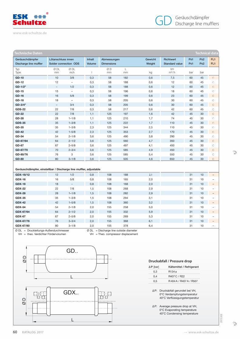
KATALOG 2017 � www.esk-schultze.de
Technische Daten Technical data
Geräuschdämpfer Lötanschluss innen Inhalt Abmessungen Gewicht Richtwert PS1 PS2 FL1 Discharge line muffler Solder connection ODS Volume Dimensions Weight Standard value PS1 PS2 FL1
Typ Ø DL Ø DL Ø D L VH Type mm inch l mm mm kg m³ / h bar bar
GD-10 10 3/8 0,3 58 182 0,6 7,5 60 45 ○
GD-12 12 – 0,3 58 188 0,6 12 60 45 ○
GD-1/2” – 1/2 0,3 58 188 0,6 12 60 45 ○
GD-15 15 – 0,3 58 196 0,6 18 60 45 ○
GD-16 16 5/8 0,3 58 199 0,6 23 60 45 ○
GD-18 18 – 0,3 58 205 0,6 30 60 45 ○
GD-3/4” – 3/4 0,3 58 205 0,6 30 60 45 ○
GDS-22 22 7/8 0,3 58 217 0,6 42 60 45 ○
GD-22 22 7/8 1,1 125 197 1,6 42 45 30 ○
GD-28 28 1–1/8 1,1 125 210 1,7 74 45 30 ○
GDS-35 35 1–3/8 1,1 125 222 1,7 110 45 30 ○
GD-35 35 1–3/8 2,3 125 344 2,5 110 45 30 ○
GD-42 42 1–5/8 2,3 125 353 2,7 170 45 30 ○
GD-54 54 2–1/8 3,6 125 490 3,8 290 45 30 ○
GD-67/64 64 2–1/2 3,6 125 560 4,7 350 45 30 ○
GD-67 67 2–5/8 3,6 125 497 4,1 450 45 30 ○
GD-67/70 70 2–3/4 3,6 125 585 4,9 450 45 30 ○
GD-80/76 76 3 3,6 125 585 5,4 550 45 30 ○
GD-80 80 3–1/8 3,6 125 505 4,6 650 45 30 ○
Geräuschdämpfer, einstellbar / Discharge line muffler, adjustable
GDX-18/12 12 1/2 0,8 108 188 2,1 31 10 – GDX-16 16 5/8 0,8 108 165 2,0 31 10 – GDX-18 18 – 0,8 108 168 2, 0 31 10 – GDX-22 22 7/8 1,5 108 268 2,9 31 10 – GDX-28 28 1–1/8 1,5 108 282 2,9 31 10 – GDX-35 35 1–3/8 1,5 108 294 3,1 31 10 – GDX-42 42 1–5/8 1,5 108 360 3,2 31 10 – GDX-54 54 2–1/8 2,0 155 258 5 ,0 31 10 – GDX-67/64 64 2–1/2 2,0 155 332 5,9 31 10 – GDX-67 67 2–5/8 2,0 155 269 5,3 31 10 – GDX-67/76 76 3–3/4 2,0 155 368 6,1 31 10 – GDX-67/80 80 3–1/8 2,0 155 378 6,4 31 10 – Ø DL = Druckleitungs-Außendurchmesser Ø DL = Discharge line outside diameter VH = theo. Verdichter Fördervolumen VH = Theo. compressor displacement
○
○
○
○
○
○
○
○
○
○
○
○
○
○
○
○
○
○
○
–––––––––––
FL1FL1
–
Druckabfall / Pressure drop
∆ P [bar] Kältemittel / Refrigerant 0,3 R 134 a 0,4 R 407 C / R 22 0,5 R 404 A / R 407 A / R 507
∆ P: Druckabfall gerundet bei VH, 0°C Verdampfungstemperatur 40°C Verflüssigungstemperatur
∆ P: Average pressure drop at VH, 0°C Evaporating temperature 40°C Condensing temperature
2015
1203
60
www.esk-schultze.de
GeräuschdämpferDischarge line mufflersGD
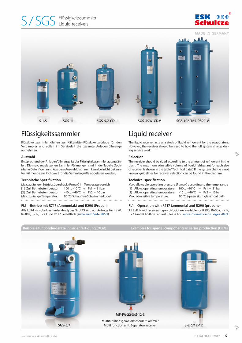
� www.esk-schultze.de CATALOGUE 2017
S-1,5 SGS-11 SGS-5,7-CD SGS-49W-CDM SGS-106/165-PS90-V1
FL1 – Betrieb mit R717 (Ammoniak) und R290 (Propan)Alle ESK-Flüssigkeitssammler des Types S / SGS sind auf Anfrage für R 290, R 600a, R 717, R 723 und R 1270 erhältlich (siehe auch Seite 70/71).
FL1 – Operation with R717 (ammonia) and R290 (propane)All ESK liquid receivers types S / SGS are available for R 290, R 600a, R 717, R 723 and R 1270 on request. Please find more information on pages 70/71.
FIüssigkeitssammlerFIüssigkeitssammler dienen zur Kältemittel-Flüs sigkeits vorlage für den Verdampfer und sollen im Servicefall die gesamte Anlagenfüllmenge aufnehmen.
AuswahlEntsprechend der Anlagenfüllmenge ist der Flüssig keits sammler auszu wäh -len. Die max. zugelassenen Sammler-Füll mengen sind in der Ta belle „Tech -nische Daten“ genannt. Aus dem Auswahl diagramm kann bei nicht be kann-ter Füllmenge ein Richtwert für die Sammler größe abgelesen werden.
Technische Spezifikation Max. zulässiger Betriebsüberdruck (PSmax) im Temperaturbereich[1] Zul. Betriebstemperatur: 100 ... –10 °C PS1 = 31 bar[2] Zul. Betriebstemperatur: –10 ... – 40°C PS2 = 10 barMax. zulässige Temperatur: 90 °C (Schauglas-Schwimmerkugel)
Liquid receiverThe liquid receiver acts as a stock of liquid refrigerant for the evaporators. However, the receiver should be sized to hold the full system charge dur-ing service work.
SelectionThe receiver should be sized according to the amount of refrigerant in the plant. The maximum admissible volume of liquid refrigerant for each size of receiver is shown in the table “Technical data”. If the system charge is not known, guidelines for receiver selection can be found in the diagram.
Technical specification Max. allowable operating pressure (PS max) according to the temp. range[1] Allow. operating temperature: 100 ... –10 °C PS1 = 31 bar [2] Allow. operating temperature: –10 ... – 40°C PS2 = 10 barMax. admissible temperature: 90 °C (green sight glass float ball)
Beispiele für Sondergeräte in Serienfertigung (OEM) Examples for special components in series production (OEM)
MF-FA-22-3/S-12-3
Multifunktionsgerät: Abscheider/Sammler SGS-5,7 Multi function unit: Separator/ receiver S-2,6/12-12
61
MADE IN GERMANY
FlüssigkeitssammlerLiquid receiversS / SGS
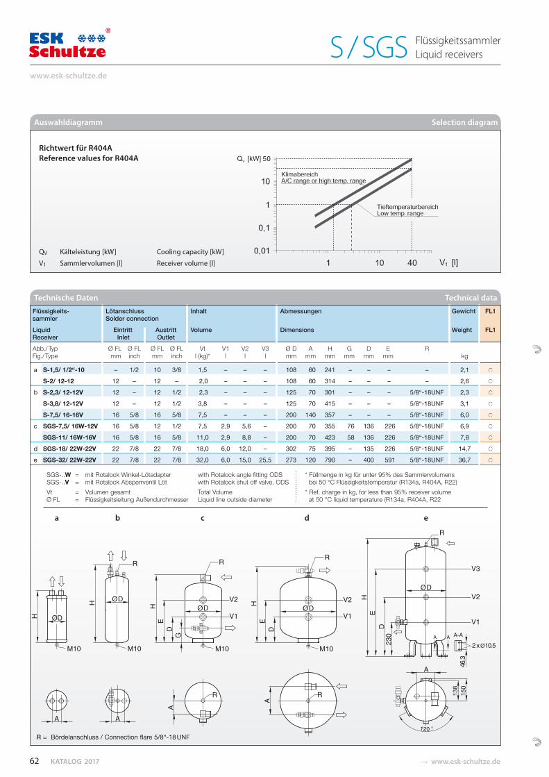
KATALOG 2017 � www.esk-schultze.de
Auswahldiagramm Selection diagram
QV Kälteleistung [kW] Cooling capacity [kW]
V1 Sammlervolumen [l] Receiver volume [l]
Richtwert für R404A Reference values for R404A
Flüssigkeits- Lötanschluss Inhalt Abmessungen Gewicht FL1 sammler Solder connection
Liquid Eintritt Austritt Volume Dimensions Weight FL1 Receiver Inlet Outlet
Abb./ Typ Ø FL Ø FL Ø FL Ø FL Vt V1 V2 V3 Ø D A H G D E R Fig./ Type mm inch mm inch l (kg)* l l l mm mm mm mm mm mm kg
a S-1,5/ 1/2“-10 – 1/2 10 3/8 1,5 – – – 108 60 241 – – – – 2,1 ○
S-2/ 12-12 12 – 12 – 2,0 – – – 108 60 314 – – – – 2,6 ○
b S-2,3/ 12-12V 12 – 12 1/2 2,3 – – – 125 70 301 – – – 5/8“-18UNF 2,3 ○
S-3,8/ 12-12V 12 – 12 1/2 3,8 – – – 125 70 415 – – – 5/8“-18UNF 3,1 ○
S-7,5/ 16-16V 16 5/8 16 5/8 7,5 – – – 200 140 357 – – – 5/8“-18UNF 6,0 ○
c SGS-7,5/ 16W-12V 16 5/8 12 1/2 7,5 2,9 5,6 – 200 70 355 76 136 226 5/8“-18UNF 6,9 ○
SGS-11/ 16W-16V 16 5/8 16 5/8 11,0 2,9 8,8 – 200 70 423 58 136 226 5/8“-18UNF 7,8 ○
d SGS-18/ 22W-22V 22 7/8 22 7/8 18,0 6,0 12,0 – 302 75 395 – 135 226 5/8“-18UNF 14,7 ○
e SGS-32/ 22W-22V 22 7/8 22 7/8 32,0 6,0 15,0 25,5 273 120 790 – 400 591 5/8“-18UNF 36,7 ○
SGS-..W = mit Rotalock Winkel-Lötadapter with Rotalock angle fitting ODS * Füllmenge in kg für unter 95% des Sammlervolumens SGS-..V = mit Rotalock Absperrventil Löt with Rotalock shut off valve, ODS bei 50 °C Flüssigkeitstemperatur (R134a, R404A, R22) Vt = Volumen gesamt Total Volume * Ref. charge in kg, for less than 95% receiver volume Ø FL = Flüssigkeitsleitung Außendurchmesser Liquid line outside diameter at 50 °C liquid temperature (R134a, R404A, R22
Technische Daten Technical data
a b c d e
FL1
FL1
○
○
○
○
○
○
○
○
○
R = Bördelanschluss / Connection flare 5/8“-18 UNF
62
www.esk-schultze.de
FlüssigkeitssammlerLiquid receiversS / SGS
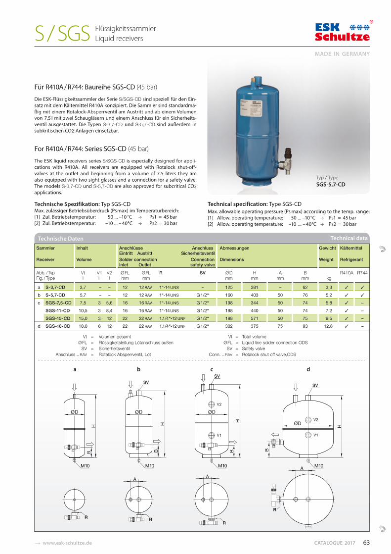
� www.esk-schultze.de CATALOGUE 2017
Für R410A / R744: Baureihe SGS-CD (45 bar)
Die ESK-Flüssigkeitssammler der Serie S/SGS-CD sind speziell für den Ein-satz mit dem Kältemittel R410A konzipiert. Die Sammler sind standardmä-ßig mit einem Rotalock-Absperrventil am Austritt und ab einem Volumen von 7,5 l mit zwei Schaugläsern und einem Anschluss für ein Sicherheits-ventil ausgestattet. Die Typen S-3,7-CD und S-5,7-CD sind außerdem in subkritischen CO2-Anlagen einsetzbar.
For R410A / R744: Series SGS-CD (45 bar)
The ESK liquid receivers series S/SGS-CD is especially designed for appli-cations with R410A. All receivers are equipped with Rotalock shut-off-valves at the outlet and beginning from a volume of 7.5 liters they are also equipped with two sight glasses and a connection for a safety valve. The models S-3,7-CD und S-5,7-CD are also approved for subcritical CO2 applications.
Technische Spezifikation: Typ SGS-CD Max. zulässiger Betriebsüberdruck (PS max) im Temperaturbereich:[1] Zul. Betriebstemperatur: 50 ... –10 °C PS1 = 45 bar[2] Zul. Betriebstemperatur: –10 ... – 40°C PS2 = 30 bar
Technical specification: Type SGS-CDMax. allowable operating pressure (PS max) according to the temp. range:[1] Allow. operating temperature: 50 ... –10 °C PS1 = 45 bar [2] Allow. operating temperature: –10 ... – 40°C PS2 = 30 bar
Typ / Type SGS-5,7-CD
SVSV
SV
V1
V2
V1
V2
RR
R
R
BB BB
a b c d
Sammler Inhalt Anschlüsse Anschluss Abmessungen Gewicht Kältemittel Eintritt Austritt Sicherheitsventil Receiver Volume Solder connection Connection Dimensions Weight Refrigerant Inlet Outlet safety valve
Abb. / Typ Vt V1 V2 Ø FL Ø FL R SV Ø D H A B R410A R744 Fig. / Type l l l mm mm mm mm mm mm kg
a S-3,7-CD 3,7 – – 12 12 RAV 1“-14 UNS – 125 381 – 62 3,3 b S-5,7-CD 5,7 – – 12 12 RAV 1“-14 UNS G 1/2“ 160 403 50 76 5,2 c SGS-7,5-CD 7,5 3 5,6 16 16 RAV 1“-14 UNS G 1/2“ 198 344 50 74 5,8 – SGS-11-CD 10,5 3 8,4 16 16 RAV 1“-14 UNS G 1/2“ 198 440 50 74 7,2 – SGS-15-CD 15,0 3 12 22 22 RAV 1.1/4“-12 UNF G 1/2“ 198 571 50 75 9,5 – d SGS-18-CD 18,0 6 12 22 22 RAV 1.1/4“-12 UNF G 1/2“ 302 375 75 93 12,8 –
Vt = Volumen gesamt Vt = Total volume Ø FL = Flüssigkeitsleitung Lötanschluss außen Ø FL = Liquid line solder connection ODS SV = Sicherheitsventil SV = Safety valve Anschluss .. RAV = Rotalock Absperrventil, Löt Conn. .. RAV = Rotalock shut off valve,ODS
Technische Daten Technical data
63
MADE IN GERMANY
FlüssigkeitssammlerLiquid receiversS / SGS
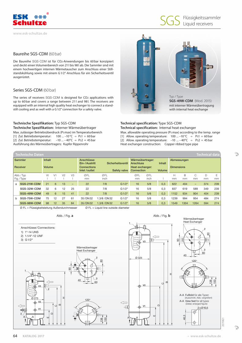
KATALOG 2017 www.esk-schultze.de
Baureihe SGS-CDM (60 bar)
Die Baureihe SGS-CDM ist für CO2-Anwendungen bis 60 bar konzi piert und deckt einen Volumenbereich von 21 l bis 98 l ab. Die Sammler sind mit einem hochwertigen internen Wärmetauscher zum Anschluss einer Still-standskühlung sowie mit einem G 1⁄2“-Anschluss für ein Sicherheitsventil ausgerüstet.
Series SGS-CDM (60 bar)
The series of receivers SGS-CDM is designed for CO2 applications with up to 60 bar and covers a range between 21 l and 98 l. The receivers are equipped with an internal high quality heat exchanger to connect a stand-still cooling and as well with a G 1⁄2” connection for a safety valve.
Technische Spezifikation: Typ SGS-CDM Technische Spezifikation: Interner Wärmeübertrager Max. zulässiger Betriebsüberdruck (PS max) im Temperaturbereich[1] Zul. Betriebstemperatur: 100 ... –10 °C PS1 = 60 bar[2] Zul. Betriebstemperatur: –10 ... – 40°C PS2 = 45 barAusführung des Wärmeübertragers: Kupfer Rippenrohr
Technical specification: Type SGS-CDMTechnical specification: Internal heat exchangerMax. allowable operating pressure (PS max) according to the temp. range[1] Allow. operating temperature: 100 ... –10 °C PS1 = 60 bar [2] Allow. operating temperature: –10 ... – 40°C PS2 = 45 bar Heat exchanger construction: Copper ribbed type pipe
Abb. / Fig. a Abb. / Fig. b
Sammler Inhalt Anschlüsse: Wärmeübertrager: Abmessungen Ein- / Austritt Sicherheitsventil Anschluss Inhalt Receiver Volume Connections Heat exchanger: Dimensions Inlet / outlet Safety valve Connection Volume
Abb. / Typ Vt V1 V2 V3 Ø FL Ø FL Ø FL Ø FL H B C D E Fig. / Type l l l l mm inch mm inch l mm mm mm mm mm
a SGS-21W-CDM 21 6 13 – 22 7/8 G 1/2“ 16 5/8 0,3 622 404 – 374 239 SGS-32W-CDM 32 6 12 25 22 7/8 G 1/2“ 16 5/8 0,3 837 619 589 349 239 SGS-49W-CDM 49 6 15 41 22 7/8 G 1/2“ 16 5/8 0,3 1152 934 904 404 239 b SGS-75W-CDM 75 12 27 61 35 / DN 32 1.3/8 / DN 32 G 1/2“ 16 5/8 0,3 1239 994 954 484 274 SGS-98W-CDM 98 12 35 84 35 / DN 32 1.3/8 / DN 32 G 1/2“ 16 5/8 0,3 1549 1304 1264 594 274 Ø FL = Flüssigkeitsleitung Außendurchmesser Ø FL = Liquid line outside diameter
Technische Daten Technical data
Anschlüsse / Connections:1) 1“-14 UNS2) 1.1/4“-12 UNF3) G 1/2“
Typ / Type SGS-49W-CDM (Mod. 2015)mit interner Wärmeübertragung with internal heat exchange
2017
0821
64
www.esk-schultze.de
FlüssigkeitssammlerLiquid receiversSGS
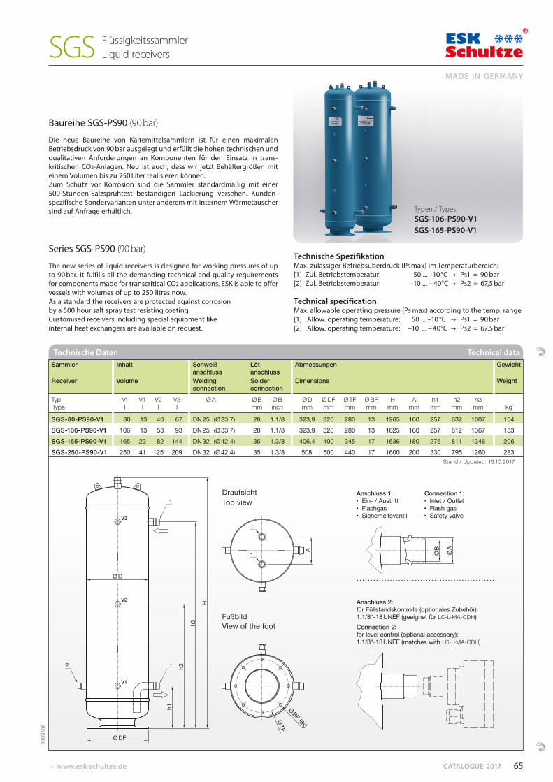
www.esk-schultze.de CATALOGUE 2017
Ø A
h1
h2
h3
H
A
Ø DF
Ø TF Ø BF (8x)
Ø B
Ø D
2
1
1
1
1
Baureihe SGS-PS90 (90 bar)
Die neue Baureihe von Kältemittelsammlern ist für einen maximalen Betriebsdruck von 90 bar ausgelegt und erfüllt die hohen technischen und qualitativen Anforderungen an Komponenten für den Einsatz in trans-kritischen CO2-Anlagen. Neu ist auch, dass wir jetzt Behältergrößen mit einem Volumen bis zu 250 Liter realisieren können.Zum Schutz vor Korrosion sind die Sammler standardmäßig mit einer 500-Stunden-Salzsprühtest beständigen Lackierung versehen. Kunden-spezifische Sondervarianten unter anderem mit internem Wärmetauscher sind auf Anfrage erhältlich.
Series SGS-PS90 (90 bar)
The new series of liquid receivers is designed for working pressures of up to 90 bar. It fulfills all the demanding technical and quality requirements for components made for transcritical CO2 applications. ESK is able to offer vessels with volumes of up to 250 litres now. As a standard the receivers are protected against corrosion by a 500 hour salt spray test resisting coating. Customised receivers including special equipment like internal heat exchangers are available on request.
Technische Spezifikation Max. zulässiger Betriebsüberdruck (PS max) im Temperaturbereich:[1] Zul. Betriebstemperatur: 50 ... –10 °C PS1 = 90 bar[2] Zul. Betriebstemperatur: –10 ... – 40°C PS2 = 67,5 bar
Technical specification Max. allowable operating pressure (PS max) according to the temp. range [1] Allow. operating temperature: 50 ... –10 °C PS1 = 90 bar [2] Allow. operating temperature: –10 ... – 40°C PS2 = 67.5 bar
Sammler Inhalt Schweiß- Löt- Abmessungen Gewicht anschluss anschluss Receiver Volume Welding Solder Dimensions Weight connection connection
Typ Vt V1 V2 V3 Ø A Ø B Ø B Ø D Ø DF Ø TF Ø BF H A h1 h2 h3 Type l l l l mm inch mm mm mm mm mm mm mm mm mm kg
SGS-80-PS90-V1 80 13 40 67 DN 25 (Ø 33,7) 28 1.1/8 323,9 320 280 13 1265 160 257 632 1007 104 SGS-106-PS90-V1 106 13 53 93 DN 25 (Ø 33,7) 28 1.1/8 323,9 320 280 13 1625 160 257 812 1367 133 SGS-165-PS90-V1 165 23 82 144 DN 32 (Ø 42,4) 35 1.3/8 406,4 400 345 17 1636 180 276 811 1346 206 SGS-250-PS90-V1 250 41 125 209 DN 32 (Ø 42,4) 35 1.3/8 508 500 440 17 1600 200 330 795 1260 283 Stand / Updated: 16.10.2017
Technische Daten Technical data
Typen / Types SGS-106-PS90-V1 SGS-165-PS90-V1
Anschluss 1: Connection 1: Ein- / Austritt Inlet / Outlet Flashgas Flash gas Sicherheitsventil Safety valve
Anschluss 2:für Füllstandskontrolle (optionales Zubehör): 1.1/8“-18 UNEF (geeignet für LC-L-MA-CDH)Connection 2: for level control (optional accessory): 1.1/8“-18 UNEF (matches with LC-L-MA-CDH)
Draufsicht Top view
Fußbild View of the foot
2016
1108
65
MADE IN GERMANY
FlüssigkeitssammlerLiquid receiversSGS
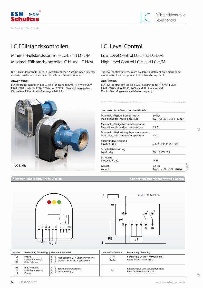
KATALOG 2017 � www.esk-schultze.de
LC FüllstandskontrollenMinimal-Füllstandskontrolle LC-L und LC-L/MMaximal-Füllstandskontrolle LC-H und LC-H/M
Die Füllstandskontrolle LC ist in unterschiedlichen Ausführungen lieferbar und wird an die entsprechenden Behälter und Geräte montiert.
AnwendungESK-Füllstandskontrollen Typ LC sind für die Kältemittel HFKW / HFCKW, R 744 (CO2) sowie für R 290, R 600a und R717 im Standard freigegeben. (Für weitere Kältemittel auf Anfrage erhältlich)
LC Level ControlLow Level Control LC-L and LC-L/MHigh Level Control LC-H and LC-H/M
The level control devices LC are available in different executions to be mounted on the correspondent vessels and equipment.
ApplicationESK level control devices type LC are approved for HFKW / HFCKW, R 744 (CO2) and for R 290, R 600a and R717 as standard. (For further refrigerants available on request)
Technische Daten / Technical data
Maximal zulässiger Betriebsdruck 60 barMax. allowable working pressure Typ / type LC-..-CDH: 130 bar
Maximal zulässige MediumtemperaturMax. allowable medium temperature 85 °C
Maximal zulässige UmgebungstemperaturMax. allowable ambient temperature 45 °C
SpannungsversorgungPower supply 230 V - 50/60 Hz ±10 %
SchaltrelaisbelastungLoad. relay Max. 250 V / 5 A
SchutzartProtection class IP 54
Gewicht 0,5 kgWeight Typ / type LC-..-CDH: 0,8 kg
Symbol Bedeutung / Meaning Klemme / Terminal Kontakt / Contact Bedeutung / Meaning
L1 Phase 1 Magnetventil y1 / Solenoid valve y1 7 .. 8 Schaltrelais (Alarm / Warnung etc.) N Nullleiter / Neutral 2 (50 Hz -18 VA, 230 V permanent) 9 .. 10 Relay (Alarm / warning …) PE Erde / Ground 3
PE Erde / Ground 4 N Nullleiter / Neutral 5
Spannungsversorgung S1
Sicherung für den Steuerstromkreis
L1 Phase 6 Voltage supply Fuse for the control circuit
Klemmen- und elektr. Anschlussplan Connection scheme and wiring diagram
2016
0615
LC-L-MR
66
www.esk-schultze.de
LC FüllstandskontrolleLevel control
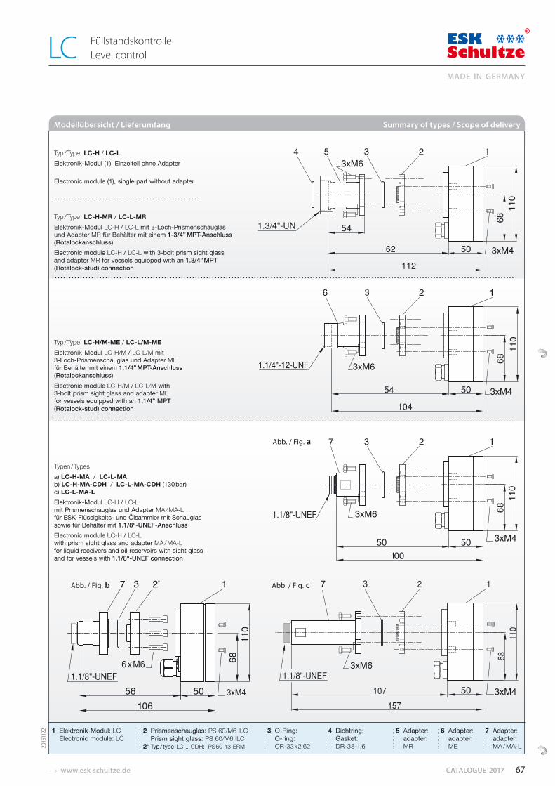
� www.esk-schultze.de CATALOGUE 2017
Modellübersicht / Lieferumfang Summary of types / Scope of delivery
2016
1122
Typ / Type LC-H / LC-L Elektronik-Modul (1), Einzelteil ohne Adapter Electronic module (1), single part without adapter
Typ / Type LC-H-MR / LC-L-MR Elektronik-Modul LC-H / LC-L mit 3-Loch-Prismenschauglas und Adapter MR für Behälter mit einem 1-3/4” MPT-Anschluss (Rotalockanschluss)Electronic module LC-H / LC-L with 3-bolt prism sight glass and adapter MR for vessels equipped with an 1.3/4” MPT (Rotalock-stud) connection
Typ / Type LC-H/M-ME / LC-L/M-ME Elektronik-Modul LC-H/M / LC-L/M mit 3-Loch-Prismenschauglas und Adapter ME für Behälter mit einem 1.1/4” MPT-Anschluss (Rotalockanschluss)Electronic module LC-H/M / LC-L/M with 3-bolt prism sight glass and adapter ME for vessels equipped with an 1.1/4” MPT (Rotalock-stud) connection
Typen / Typesa) LC-H-MA / LC-L-MA b) LC-H-MA-CDH / LC-L-MA-CDH (130 bar) c) LC-L-MA-L Elektronik-Modul LC-H / LC-L mit Prismen schauglas und Adapter MA / MA-L für ESK-Flüssigkeits- und Ölsammler mit Schau glas sowie für Behälter mit 1.1/8“-UNEF-AnschlussElectronic module LC-H / LC-L with prism sight glass and adapter MA / MA-L for liquid receivers and oil reservoirs with sight glass and for vessels with 1.1/8“-UNEF connection
1 Elektronik-Modul: LC Electronic module: LC
4 Dichtring: Gasket: DR-38-1,6
5 Adapter: adapter: MR
6 Adapter: adapter: ME
7 Adapter: adapter: MA / MA-L
2 Prismenschauglas: PS 60/M6 ILC Prism sight glass: PS 60/M6 ILC2* Typ / type LC-..-CDH: PS 60-13-ERM
3 O-Ring: O-ring: OR-33 x 2,62
Abb. / Fig. b Abb. / Fig. c
Abb. / Fig. a
67
MADE IN GERMANY
LC FüllstandskontrolleLevel control
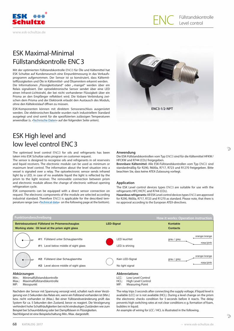
KATALOG 2017 www.esk-schultze.de
Nachdem der Sensor mit Spannung versorgt wird, schaltet nach einer Verzö-gerung von 3 Sekunden das Relais ein, wenn ein Füllstand vorhanden ist (Min.) bzw. nicht vorhanden ist (Max.). Bei einer Füllstandsveränderung prüft das System für ca. 5 Sekunden den Zustand, bevor es reagiert. Die Verzögerung verhindert hohe Schalthäufigkeiten bei nicht eindeutigen Zuständen wie zum Beispiel bei Schaumbildung oder bei Dampfblasen in Flüssigkeiten. Nachfolgend ist eine Beispielschaltung Min. /Max. dargestellt.
The relay trips 3 seconds after connecting the supply voltage, if liquid level is available (LCC) or is not available (HCL). During a level change on the prism the electronic checks condition for 5 seconds before it reacts. The delay prevents high switching rates at not clear conditions e. g. formation of foam, bubbles in liquid. An example of wiring for LCC / HCL is illustrated in the following.
ESK Maximal-MinimalFüllstandskontrolle ENC 3Mit der optimierten Füllstandskontrolle ENC3 für Öle und Kältemittel hat ESK Schultze auf Kundenwunsch eine Einpunktmessung in das Verkaufs-programm aufgenommen. Der Sensor ist so konstruiert, dass Kältemit-telflüssigkeiten und Öle in Kälte mittel- und Ölsammlern erkannt werden. Die Informationen „Flüssig keits stand“ oder „-mangel“ werden über ein Relais signalisiert. Der optoelektronische Sensor sendet über eine LED einen Infrarot-Lichtstrahl, der bei nicht vorhandener Flüssigkeit über ein Prisma an den Empfänger reflektiert wird. Die lösbare Verbindung zwi-schen dem Prisma und der Elektronik erlaubt den Austausch des Moduls, ohne den Kältekreislauf öffnen zu müssen.
ESK-Komponenten können mit direktem Sensoranschluss ausgerüstet werden. Die elektronischen Bauteile wurden nach industriellem Standard ausgelegt und sind somit für die spezifizierten zulässigen Temperaturen anwendbar (s. »Technische Daten« auf der folgenden Seite unten).
ENC3-1/2-NPT
ESK High level and low level control ENC 3The optimised level control ENC3 for oils and refrigerants has been taken into ESK Schultze sales program on customer request. The sensor is designed to recognise oils and refrigerants in oil reservoirs and liquid receivers. The electronic module can be used as minimum or maximum level control. The information about the level situation into a vessel is signaled over a relay. The optoelectronic sensor sends infrared light by a LED, in case of no available liquid the light is reflected by the prism to the light receiver. The removable connection between prism and electronic module allows the change of electronic without opening refrigeration cycle.ESK components can be equipped with a direct sensor connection on request. The electronic components of the module are selected according industrial standard. Therefore ENC3 is applicable for the described tem-perature range (see »Technical data« on the following page at the bottom).
AnwendungDie ESK-Füllstandskontrollen vom Typ ENC3 sind für die Kältemittel HFKW / HFCKW und R744 (CO2) freigegeben. Brennbare Kältemittel: Alle ESK-Füllstandskontrollen vom Typ ENC3 sind standardmäßig für R290, R600a, R717, R723 und R1270 freigegeben. Bitte beachten Sie, dass keine ATEX-Zulassung vorliegt.
ApplicationThe ESK Level control devices types ENC3 are suitable for use with the refrigerants HFC/HCFC and R744 (CO2).Hazardous refrigerants: All ESK Level control devices types ENC3 are approved for R290, R600a, R717, R723 and R1270 as standard. Please note, that there is no approval according to the European ATEX-directives.
AbkürzungenMin.: Minimalfüllstandskontrolle Max.: Maximalfüllstandskontrolle MP: Messpunkt
Abbreviations LCC: Low Level Control HCL: High Level Control MP: Measuring Point
Funktionsbeschreibung How it works: Operation instruction
Betriebszustand: Füllstand im Prismenschauglas LED-Signal Kontakte Working state: Oil level at the prism sight glass Contacts
# 1: Füllstand unter Schauglasmitte LED leuchtet grau / grey
orange /orange
# 1: Level below middle of sight glass LED is shining rosa /pink
# 2: Füllstand über Schauglasmitte Kein LED-Signal grau / grey
orange /orange
# 2: Level above middle of sight glass No light signal rosa /pink
68
www.esk-schultze.de
FüllstandskontrolleLevel controlENC
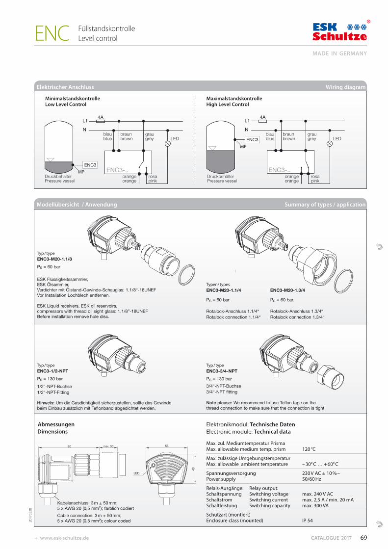
www.esk-schultze.de CATALOGUE 2017
Modellübersicht / Anwendung Summary of types / application
Typ / type ENC3-M20-1.1/8
PS = 60 bar
ESK Flüssigkeitssammler, ESK Ölsammler, Verdichter mit Ölstand-Gewinde-Schauglas: 1.1/8“-18UNEF Vor Installation Lochblech entfernen.
ESK Liquid receivers, ESK oil reservoirs, compressors with thread oil sight glass: 1.1/8”-18UNEF Before installation remove hole disc.
Typ / type ENC3-1/2-NPT
PS = 130 bar 1/2“-NPT-Buchse 1/2“-NPT-Fitting
Hinweis: Um die Gasdichtigkeit sicherzustellen, sollte das Gewinde beim Einbau zusätzlich mit Teflonband abgedichtet werden.
Typen/ typesENC3-M20-1.1/4 ENC3-M20-1.3/4
PS = 60 bar PS = 60 bar
Rotalock-Anschluss 1.1/4“ Rotalock-Anschluss 1.3/4“Rotalock connection 1.1/4“ Rotalock connection 1.3/4“
Typ / typeENC3-3/4-NPT
PS = 130 bar3/4“-NPT-Buchse3/4“-NPT fitting
Note please: We recommend to use Teflon tape on the thread connection to make sure that the connection is tight.
Abmessungen Dimensions
2017
0328
Elektronikmodul: Technische Daten Electronic module: Technical data
Max. zul. Mediumtemperatur PrismaMax. allowable medium temp. prism 120 °C
Max. zulässige UmgebungstemperaturMax. allowable ambient temperature – 30° C … + 60° C
Spannungsversorgung 230 V AC ± 10 % – Power supply 50/60 Hz
Relais-Ausgänge: Relay output:Schaltspannung Switching voltage max. 240 V ACSchaltstrom Switching current max. 2,5 A / min. 20 mASchaltleistung Switching capacity max. 300 VA
Schutzart (montiert)Enclosure class (mounted) IP 54
Kabelanschluss: 3 m ± 50 mm; 5 x AWG 20 (0,5 mm2); farblich codiertCable connection: 3 m ± 50 mm; 5 x AWG 20 (0,5 mm2); colour coded
80 max. 30 55
LED
40
4A
ENC3-..ENC3
4A
ENC3-..
ENC3
Minimalstandskontrolle Maximalstandskontrolle Low Level Control High Level Control
Druckbehälter orange rosaPressure vessel orange pink
Druckbehälter orange rosaPressure vessel orange pink
blau braun grau blue brown grey LED
blau braun grau blue brown grey LED
Elektrischer Anschluss Wiring diagram
69
MADE IN GERMANY
FüllstandskontrolleLevel controlENC
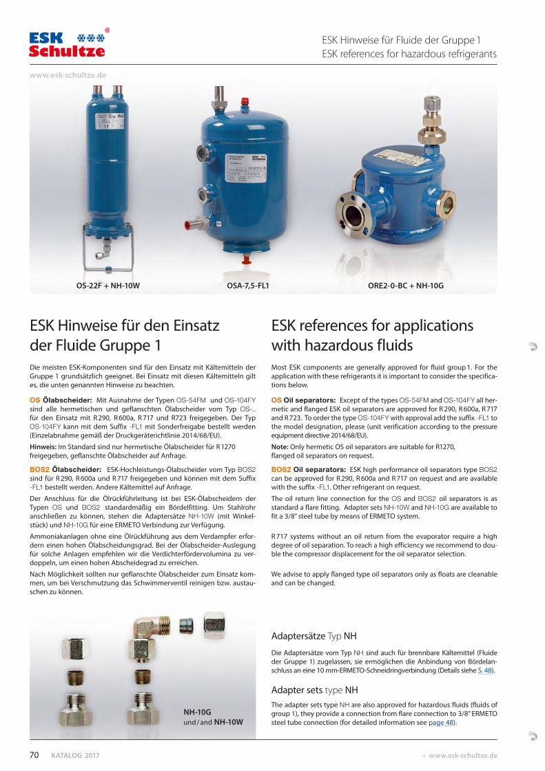
KATALOG 2017 www.esk-schultze.de
Adaptersätze Typ NH
Die Adaptersätze vom Typ NH sind auch für brennbare Kältemittel (Fluide der Gruppe 1) zugelassen, sie ermöglichen die Anbindung von Bördelan-schluss an eine 10 mm-ERMETO-Schneidringverbindung (Details siehe S. 48).
Adapter sets type NH The adapter sets type NH are also approved for hazardous fluids (fluids of group 1), they provide a connection from flare connection to 3/8” ERMETO steel tube connection (for detailed information see page 48).
ESK Hinweise für den Einsatz der Fluide Gruppe 1Die meisten ESK-Komponenten sind für den Einsatz mit Kältemitteln der Gruppe 1 grundsätzlich geeignet. Bei Einsatz mit diesen Kältemitteln gilt es, die unten genannten Hinweise zu beachten.
OS Ölabscheider: Mit Ausnahme der Typen OS-54FM und OS-104FY sind alle hermetischen und geflanschten Ölabscheider vom Typ OS-.. für den Einsatz mit R 290, R 600a, R 717 und R723 freigegeben. Der Typ OS-104FY kann mit dem Suffix -FL1 mit Sonderfreigabe bestellt werden (Einzelabnahme gemäß der Druckgeräterichtlinie 2014/68/EU).
Hinweis: Im Standard sind nur hermetische Ölabscheider für R 1270 freigegeben, geflanschte Ölabscheider auf Anfrage.
BOS2 Ölabscheider: ESK-Hochleistungs-Ölabscheider vom Typ BOS2 sind für R 290, R 600a und R 717 freigegeben und können mit dem Suffix -FL1 bestellt werden. Andere Kältemittel auf Anfrage.
Der Anschluss für die Ölrückführleitung ist bei ESK-Ölabscheidern der Typen OS und BOS2 standardmäßig ein Bördelfitting. Um Stahlrohr anschließen zu können, stehen die Adaptersätze NH-10W (mit Winkel-stück) und NH-10G für eine ERMETO Verbindung zur Verfügung.
Ammoniakanlagen ohne eine Ölrückführung aus dem Verdampfer erfor-dern einen hohen Ölabscheidungsgrad. Bei der Ölabscheider-Auslegung für solche Anlagen empfehlen wir die Verdichterfördervolumina zu ver-doppeln, um einen hohen Abscheidegrad zu erreichen.
Nach Möglichkeit sollten nur geflanschte Ölabscheider zum Einsatz kom-men, um bei Verschmutzung das Schwimmerventil reinigen bzw. austau-schen zu können.
ESK references for applications with hazardous fluids Most ESK components are generally approved for fluid group 1. For the application with these refrigerants it is important to consider the specifica-tions below.
OS Oil separators: Except of the types OS-54FM and OS-104FY all her-metic and flanged ESK oil separators are approved for R 290, R 600a, R 717 and R 723. To order the type OS-104FY with approval add the suffix -FL1 to the model designation, please (unit verification according to the pressure equipment directive 2014/68/EU).
Note: Only hermetic OS oil separators are suitable for R1270, flanged oil separators on request.
BOS2 Oil separators: ESK high performance oil separators type BOS2 can be approved for R 290, R 600a and R 717 on request and are available with the suffix -FL1. Other refrigerant on request.
The oil return line connection for the OS and BOS2 oil separators is as standard a flare fitting. Adapter sets NH-10W and NH-10G are available to fit a 3/8” steel tube by means of ERMETO system.
R 717 systems without an oil return from the evaporator require a high degree of oil separation. To reach a high efficiency we recommend to dou-ble the compressor displacement for the oil separator selection.
We advise to apply flanged type oil separators only as floats are cleanable and can be changed.
OS-22F + NH-10W OSA-7,5-FL1 ORE2-0-BC + NH-10G
NH-10Gund / and NH-10W
ESK Hinweise für Fluide der Gruppe 1ESK references for hazardous refrigerants
70
www.esk-schultze.de
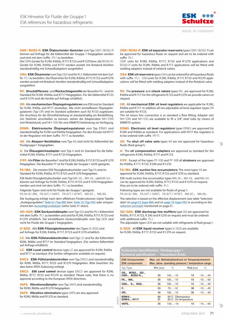
www.esk-schultze.de CATALOGUE 2017
ESK Komponenten Max. zul. Betriebsüberdruck im Temperaturbereich ESK components Max. allow. operating pressure / temperature range
Typ / Type PS1 [bar] °C PS2 [bar] °C
OS.., BOS2.., GD.., OSR.., BOS2-R.., 25 140 … -10 10 -10 … -40 FA.., MA.. 25 100 … -10 15 -10 … -50 OSA.., S.., SGS.. 25 100 … -10 10 -10 … -40 F.. 53 70 … -10 39 -10 … -40 OR.. 40 100 … -10 30 -10 … -40 ERM 5-.. 60 85°C Öltemperatur ERM 5-..-R717 31 85°C Oil temperature VAFS.. 25 140 … -10 10 -10 … -50
OSR / BOS2-R: ESK Ölabscheider-Sammler vom Typ OSR / BOS2-R können auf Anfrage für die Kältemittel der Gruppe 1 freigegeben werden und sind mit dem Suffix –FL1 zu bestellen. Die OSR-Geräte für R 290, R 600a, R 717, R 723 und R 1270 bzw. die BOS2-R-Geräte für R 290, R 600a und R 717 werden anstatt mit Rotalock-Ventilen standardmäßig mit Schweiß adaptern ausgeliefert.
OSA: ESK Ölsammler vom Typ OSA sind für FL1-Kältemittel mit dem Suf-fix -FL1 zu bestellen. Die Ölsammler für R 290, R 600a, R 717, R 723 und R1270 werden anstatt mit Rotalock-Ventilen standardmäßig mit Schweiß adaptern ausgeliefert.
RV : Druckdifferenz- und Rückschlagventile der Baureihe RV.. sind im Standard für R 290, R 600a und R 717 freigegeben. Für die Kältemittel R 723 und R 1270 sind die Ventile auf Anfrage erhältlich.
OR: Alle mechanischen Ölspiegelregulatoren von ESK sind im Standard für R 290, R 600a und R717 einsetzbar. Alle nicht einstellbaren Ölspiegelre-gulatoren (Typ OR) sind im Standard außerdem auch für R 723 zugelassen. Der Anschluss für die Ölrückführleitung ist standardmäßig ein Bördelfitting. Um Stahlrohr anschließen zu können, stehen die Adaptersätze NH-10W (mit Winkelstück) und NH-10G für eine ERMETO Verbindung zur Verfügung.
ERM5: Elektronische Ölspiegelregulatoren vom Typ ERM 5 sind standardmäßig für R 290 und R 600a freigegeben. Für den Einsatz mit R717 ist der Regulator mit dem Suffix -R717 zu bestellen.
AS: Die Absperr-Ventilsätze vom Typ AS sind nicht für Kältemittel der Fluidgruppe 1 freigegeben.
A: Die Ölausgleichsadapter vom Typ A sind im Standard für die Kälte-mittel R 290, R 600a, R 717 und R 723 freigegeben.
F/FF: Alle Filter der Baureihe F sind für R 290, R 600a, R 717, R 723 und R 1270 freigegeben. Die Baureihe FF ist für Fluide der Gruppe 1 nicht geeignet.
FA / MA: Die meisten ESK Flüssigkeitsabscheider vom Typ FA sind im Standard für R 290, R 600a, R 717, R 723 und R 1270 freigegeben.
ESK Multi-Flüssigkeitsabscheider vom Typ MA-35.., MA-42.. und MA-54.. können auf Anfrage für R 290, R 600a, R 717, R 723 und R 1270 freigegeben werden und sind mit dem Suffix -FL1 zu bestellen.
Folgende Typen sind nicht für Fluide der Gruppe 1 geeignet: FA-54-9 / -9W, FA-54T / -54WT, FA-67T / -67WT, MA-67.., MA-80..Die Auslegung erfolgt nach dem effektiven Fördervolumen (siehe Tabelle „Auslegungsdaten“ Seite 52 (Typ MA) bzw. Seite 53 (Typ FA)) oder entspre-chend den Aus wahl grundsätzen (siehe Seite 51 oben).
GD / GDX: ESK Geräuschdämpfer vom Typ GD sind für FL1-Kältemittel mit dem Suffix -FL1 zu bestellen und sind für R 290, R 600a, R 717, R 723 und R 1270 erhältlich. Die einstellbaren Geräuschdämpfer vom Typ GDX sind nicht für Fluide der Gruppe 1 freigegeben.
S / SGS: Alle ESK-Flüssigkeitssammler des Types S / SGS sind auf Anfrage für R 290, R 600a, R 717, R 723 und R 1270 erhältlich.
LC: Alle ESK-Füllstandskontrollen vom Typ LC sind für die Kältemittel R290, R600a und R717 im Standard freigegeben. (Für weitere Kältemittel auf Anfrage erhältlich)
LC: ESK Level control devices type LC are approved for R 290, R 600a and R717 as standard. (For further refrigerants available on request)
ENC3: ESK-Füllstandskontrollen vom Typ ENC3 sind standard mäßig für R290, R600a, R717, R723 und R1270 freigegeben. Bitte beachten Sie, dass keine ATEX-Zulassung vorliegt.
ENC3: ESK Level control devices types ENC3 are approved for R290, R600a, R717, R723 and R1270 as standard. Please note, that there is no approval according to the European ATEX-directives.
VAFS: Vibrationsdämpfer vom Typ VAFS sind standard mäßig für R290, R600a und R1270 freigegeben.
VAFS: Vibration eliminators types VAFS are also approved for R290, R600a and R1270 as standard.
OSR / BOS2-R: ESK oil separator reservoirs types OSR / BOS2-R can be approved for hazardous fluids on request and are to be ordered with suffix -FL1. OSR units for R 290, R 600a, R 717, R 723 and R 1270 applications and BOS2-R units for R 290, R 600a and R 717 applications will be fitted with welding adapters instead of rotalock valves.
OSA: ESK oil reservoirs types OSA can be ordered for all hazardous fluids with suffix -FL1. OSA units for R 290, R 600a, R 717, R 723 and R1270 appli-cations will be fitted with welding adapters instead of the Rotalock valve.
RV: The pressure and check valves types RV.. are approved for R 290, R 600a and R 717. For the refrigerants R 723 and R 1270 we provide valves on request.
OR: All mechanical ESK oil level regulators are applicable for R 290, R 600a and R 717. In addition all not adjustable oil level regulator types OR are suitable for R 723. The oil return line connection is as standard a flare fitting. Adapter sets NH-10W and NH-10G are available to fit a 3/8” steel tube by means of ERMETO system.
ERM5: Electronic oil level regulators types ERM 5 are approved for R 290 and R 600a as standard. For applications with R717 the regulator is to be ordered with suffix -R717.
AS: The shut off valve sets types AS are not approved for hazardous fluids (fluid group1).
A: The oil compensation adapters are approved as standard for the refrigerants R 290, R 600a, R 717 and R 723.
F/FF: Except of the types FF-10B and FF-16B all strainers are approved for R 600a, R 717, R 723, R 290 and R 1270.
FA / MA: ESK suction line accumulators: The most types FA are approved for R 290, R 600a, R 717, R 723 and R 1270 as standard.
ESK multi suction line accumulator types MA-35.., MA-42.. and MA-54.. can be approved for R 290, R 600a, R 717, R 723 and R 1270 on request,they are to be ordered with suffix -FL1.
Following types are not available for fluids of group 1: FA-54-9 / -9W, FA-54T / -54WT, FA-67T / -67WT, MA-67.., MA-80..The selection is based on the effective displacement (see table “Selection data” on page 52 (type MA) and on page 53 (type FA)) or according to the selection principle mentioned on page 51.
GD / GDX: ESK discharge line mufflers type GD are approved for R 600a, R 717, R 723, R 290 and R 1270 on request and must be ordered with additional suffix -FL1. The adjustable types GDX are not suitable with refrigerants of fluid group 1.
S / SGS: All ESK liquid receiver types S / SGS are available for R 290, R 600a, R 717, R 723 and R 1270 on request.
ESK Hinweise für Fluide der Gruppe 1ESK references for hazardous refrigerants
Technische Spezifikation: Fluidegruppe 1 Technical specification: Hazardous fluids
2016
0121
71
MADE IN GERMANY
AC
CE
SS
OR
IES
ZUBEHÖR UND ERSATZTEILEVAFS Schwingungsdämpfung PS max: 60 bar 73
Schaugläser 74 NEU: PS max: 60 / 160 bar 75
Heizelemente / Heizbänder 76
Rotalock-Ventile und Fittings 76
Schweißstutzen und -adapter 77
Schwimmer-Flanschplatte 78
Filterpatronen 78
Dichtungen und O-Ringe 79
ACCESSORIES AND SPARE PARTSVAFS Vibration eliminators PS max: 60 bar 73
Sight glasses 74 NEW: PS max: 60 / 160 bar 75
Heater elements / Heater bands 76
Rotalock valves and fittings 76
Weld-solder connectors and adapters 77
Flange plate with float valve 78
Replacement elements 78
Gaskets and O-rings 79
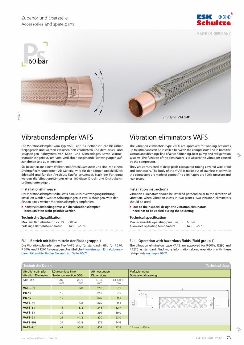
� www.esk-schultze.de CATALOGUE 2017
Vibrationsdämpfer VAFSDie Vibrationsdämpfer vom Typ VAFS sind für Betriebsdrücke bis 60 bar freigegeben und werden zwischen den Verdichtern und dem druck- und saugseitigen Rohrsystem von Kälte- und Klimaanlagen sowie Wärme-pumpen eingebaut, um vom Verdichter ausgehende Schwingungen auf-zunehmen und zu eliminieren.
Sie bestehen aus einem Wellrohr mit Anschlussstutzen und sind mit einem Drahtgeflecht ummantelt. Als Material wird für den Körper ausschließlich Edelstahl und für den Anschluss Kupfer verwendet. Nach der Fertigung werden die Vibrationsdämpfer einer 100%igen Druck- und Dichtigkeits-prüfung unterzogen.
InstallationshinweiseDer Vibrationsdämpfer sollte stets parallel zur Schwingungsrichtung installiert werden. Gibt es Schwingungen in zwei Richtungen, wird der Einbau eines zweiten Vibrationsdämpfers empfohlen.
� Konstruktionsbedingt müssen die Vibrationsdämpfer beim Einlöten nicht gekühlt werden.
Technische Spezifikation Max. zul. Betriebsüberdruck PS 60 bar Zulässige Betriebstemperatur 140 … –50°C
FL1 – Betrieb mit Kältemitteln der Fluidegruppe 1Die Vibrationsdämpfer vom Typ VAFS sind für standardmäßig für R 290, R 600a und R 1270 freigegeben. Ausführliche Hinweise zum Einsatz brenn-barer Kältemittel finden Sie auch auf Seite 70/71.
Vibration eliminators VAFS The vibration eliminators type VAFS are approved for working pressures up to 60 bar and can be installed between the compressors and in both the suction and discharge line of air conditioning, heat pump and refrigeration systems. The function of the eliminators is to absorb the vibrations caused by the compressor.
They are constructed of deep pitch corrugated tubing covered wire braid and connectors. The body of the VAFS is made out of stainless steel while the connectors are made of copper.The eliminators are 100% pressure and leak tested.
Installation instructionsVibration eliminators should be installed perpendicular to the direction of vibration. When vibration exists in two planes, two vibration eliminators should be used.
� Due to their special design the vibration eliminators need not to be cooled during the soldering.
Technical specification Max. admissible operating pressure PS 60 bar Allowable operating temperature 140 … –50°C
FL1 – Operation with hazardous fluids (fluid group 1)The vibration eliminators type VAFS are approved for R 600a, R 290 and R 1270 as standard. Find more information about operations with these refrigerants on pages 70/71.
Typ / Type VAFS-81
60 bar
2016
0121
Vibrationsdämpfer Lötanschluss innen Abmessungen Maßzeichnung Vibration Eliminator Solder connection ODS Dimensions Dimensional drawingTyp / Type Ø D1 Ø D1 L (± 5) L1 (± 0,1) mm inch mm mm
VAFS-31 – 3/8 210 7,9 PS-10 10 – 210 7,9 PS-12 12 – 230 9,5 VAFS-41 – 1/2 230 9,5 VAFS-51 16 5/8 248 12,7 VAFS-81 22 7/8 292 19,0 VAFS-91 28 1-1/8 330 23,0 VAFS-101 35 1-3/8 375 24,6 VAFS-11* 42 1-5/8 432 27,8 * PSmax = 45 bar
Technische Daten Technical data
73
MADE IN GERMANY
Zubehör und ErsatzteileAccessories and spare parts
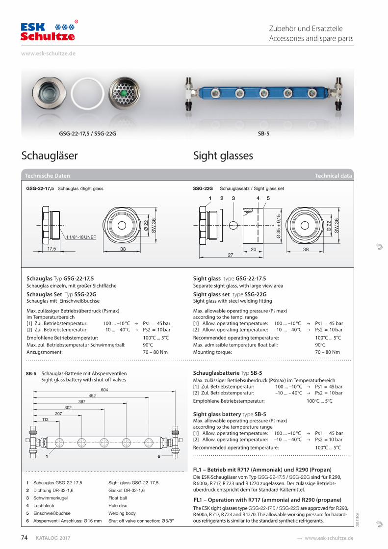
KATALOG 2017 � www.esk-schultze.de
17,5 38
Ø 2
2
SW
36
1 2 3 4 5
2720 38
Ø 2
2
SW
36
Ø 3
5 ±
0,15
Schaugläser Sight glasses
GSG-22-17,5 / SSG-22G SB-5
Technische Daten Technical data
Schauglasbatterie Typ SB-5 Max. zulässiger Betriebsüberdruck (PSmax) im Temperaturbereich[1] Zul. Betriebstemperatur: 100 ... –10 °C PS1 = 45 bar[2] Zul. Betriebstemperatur: –10 ... – 40°C PS2 = 10 bar
Empfohlene Betriebstemperatur: 100°C ... 5°C Sight glass battery type SB-5 Max. allowable operating pressure (PS max) according to the temperature range[1] Allow. operating temperature: 100 ... –10 °C PS1 = 45 bar [2] Allow. operating temperature: –10 ... – 40°C PS2 = 10 bar
Recommended operating temperature: 100°C ... 5°C
1 Schauglas GSG-22-17,5 Sight glass GSG-22-17,52 Dichtung DR-32-1,6 Gasket DR-32-1,63 Schwimmerkugel Float ball4 Lochblech Hole disc5 Einschweißbuchse Welding body6 Absperrventil Anschluss: Ø 16 mm Shut off valve connection: Ø 5/8”
1 6
604492
397302
207112
FL1 – Betrieb mit R717 (Ammoniak) und R290 (Propan)Die ESK-Schaugläser vom Typ GSG-22-17.5 / SSG-22G sind für R 290, R 600a, R 717, R 723 und R 1270 zugelassen. Der zulässige Betriebs-überdruck entspricht dem für Standard-Kältemittel.
FL1 – Operation with R717 (ammonia) and R290 (propane)The ESK sight glasses type GSG-22-17.5 / SSG-22G are approved for R 290, R 600a, R 717, R 723 and R 1270. The allowable working pressure for hazard-ous refrigerants is similar to the standard synthetic refrigerants.
GSG-22-17,5 Schauglas /Sight glass SSG-22G Schauglassatz / Sight glass set
SB-5 Schauglas-Batterie mit Absperrventilen Sight glass battery with shut-off-valves
Schauglas Typ GSG-22-17,5Schauglas einzeln, mit großer Sichtfläche
Schauglas Set Typ SSG-22G Schauglas mit Einschweißbuchse
Max. zulässiger Betriebsüberdruck (PSmax) im Temperaturbereich[1] Zul. Betriebstemperatur: 100 ... –10 °C PS1 = 45 bar[2] Zul. Betriebstemperatur: –10 ... – 40°C PS2 = 10 bar
Empfohlene Betriebstemperatur: 100°C ... 5°CMax. zul. Betriebstemperatur Schwimmerball: 90°C Anzugsmoment: 70 – 80 Nm
Sight glass type GSG-22-17.5Separate sight glass, with large view area
Sight glass set type SSG-22G Sight glass with steel welding fitting
Max. allowable operating pressure (PS max) according to the temp. range[1] Allow. operating temperature: 100 ... –10 °C PS1 = 45 bar [2] Allow. operating temperature: –10 ... – 40°C PS2 = 10 bar
Recommended operating temperature: 100°C ... 5°CMax. admissible temperature float ball: 90°C Mounting torque: 70 – 80 Nm
2015
1106
74
www.esk-schultze.de
Zubehör und ErsatzteileAccessories and spare parts
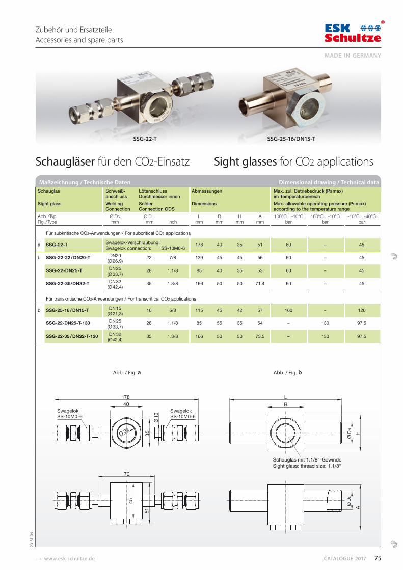
� www.esk-schultze.de CATALOGUE 2017
Schaugläser für den CO2-Einsatz Sight glasses for CO2 applications
Maßzeichnung / Technische Daten Dimensional drawing / Technical data
SSG-22-T SSG-25-16/DN15-T
2015
1106
Schauglas Schweiß- Lötanschluss Abmessungen Max. zul. Betriebsdruck (PS max) anschluss Durchmesser innen im Temperaturbereich Sight glass Welding Solder Dimensions Max. allowable operating pressure (PS max) Connection Connection ODS according to the temperature rangeAbb. /Typ Ø DN Ø DL L B H A 100°C…-10°C 160°C…-10°C -10°C…-40°CFig. / Type mm mm inch mm mm mm mm bar bar bar
Für subkritische CO2-Anwendungen / For subcritical CO2 applications
a SSG-22-T Swagelok-Verschraubung: 178 40 35 51 60 – 45 Swagelok connection: SS-10M0-6
b SSG-22-22 / DN20-T DN20 22 7/8 139 45 45 56 60 – 45 (Ø 26,9)
SSG-22-DN25-T DN 25 28 1.1/8 85 40 35 53 60 – 45 (Ø 33,7)
SSG-22-35/DN32-T DN 32 35 1.3/8 166 50 50 71.4 60 – 45 (Ø 42,4)
Für transkritische CO2-Anwendungen / For transcritical CO2 applications
b SSG-25-16 / DN15-T DN 15 16 5/8 115 45 42 57 160 – 120 (Ø 21,3) SSG-22-DN25-T-130 DN 25 28 1.1/8 85 55 35 54 – 130 97.5 (Ø 33,7)
SSG-22-35 / DN32-T-130 DN 32 35 1.3/8 166 50 50 73.5 – 130 97.5 (Ø42,4)
Abb. / Fig. a Abb. / Fig. b
51
17840
Ø 10
35
70
Ø 22
45
SwagelokSS-10M0-6
SwagelokSS-10M0-6
HØ D
NØ
DL
Schauglas mit 1.1/8“-Gewinde Sight glass: thread size: 1.1/8“
A
LB
75
MADE IN GERMANY
Zubehör und ErsatzteileAccessories and spare parts
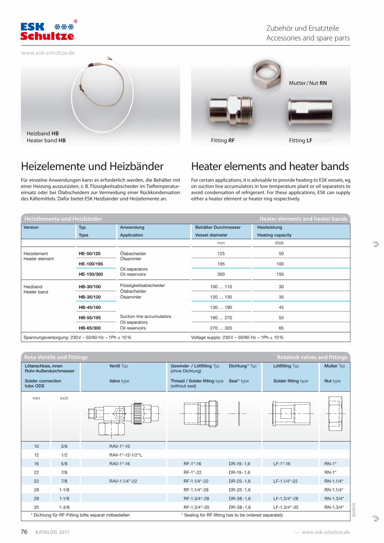
KATALOG 2017 � www.esk-schultze.de
Heizelemente und HeizbänderFür einzelne Anwendungen kann es erforderlich werden, die Behälter mit einer Heizung auszurüsten, z. B. Flüssigkeits ab scheider im Tieftemperatur-einsatz oder bei Ölabscheidern zur Vermeidung einer Rück kondensation des Kältemittels. Dafür bietet ESK Heiz bän der und Heizelemente an.
Heater elements and heater bandsFor certain applications, it is advisable to provide heat ing to ESK vessels, eg on suction line accumulators in low temperature plant or oil separators to avoid con densation of refrigerant. For these applications, ESK can supply either a heater element or heater ring respectively.
Fitting RF Fitting LF
Heizband HBHeater band HB
Mutter / Nut RN
Rota-Ventile und Fittings Rotalock valves and fittings
Lötanschluss, innen Ventil Typ Gewinde- / Lötfitting Typ Dichtung * Typ Lötfitting Typ Mutter Typ Rohr-Außendurchmesser (ohne Dichtung) Solder connection Valve type Thread / Solder fitting type Seal * type Solder fitting type Nut type tube ODS (without seal) mm inch
10 3/8 RAV-1“-10
12 1/2 RAV-1“-12-1/2“L
16 5/8 RAV-1“-16 RF-1“-16 DR-19 - 1,6 LF-1“-16 RN-1“
22 7/8 RF-1“-22 DR-19 - 1,6 RN-1“
22 7/8 RAV-1.1/4”-22 RF-1.1/4“-22 DR-25 - 1,6 LF-1.1/4“-22 RN-1.1/4“
28 1-1/8 RF-1.1/4“-28 DR-25 - 1,6 RN-1.1/4“
28 1-1/8 RF-1.3/4“-28 DR-38 - 1,6 LF-1.3/4“-28 RN-1.3/4“
35 1-3/8 RF-1.3/4“-35 DR-38 - 1,6 LF-1.3/4“-35 RN-1.3/4“ * Dichtung für RF-Fitting bitte separat mitbestellen * Sealing for RF-fitting has to be ordered separately
Heizelemente und Heizbänder Heater elements and heater bands Version Typ Anwendung Behälter Durchmesser Heizleistung Type Application Vessel diameter Heating capacity
mm Watt
Heizelement HE-50/125 Ölabscheider 125 50 Heater element Ölsammler HE-100/195 195 100 Oil separators HE-150/300 Oil reservoirs 300 150
Heizband HB-30/100 Flüssigkeitsabscheider 100 … 110 30 Heater band Ölabscheider HB-35/120 Ölsammler 120 … 130 35 HB-45/160 130 … 190 45
HB-55/195 Suction line accumulators 190 … 270 55 Oil separators HB-65/300 Oil reservoirs 270 … 320 65
Spannungsversorgung: 230 V – 50/60 Hz – 1Ph ± 10 % Voltage supply: 230 V – 50/60 Hz – 1Ph ± 10 %
2015
0119
76
www.esk-schultze.de
Zubehör und ErsatzteileAccessories and spare parts
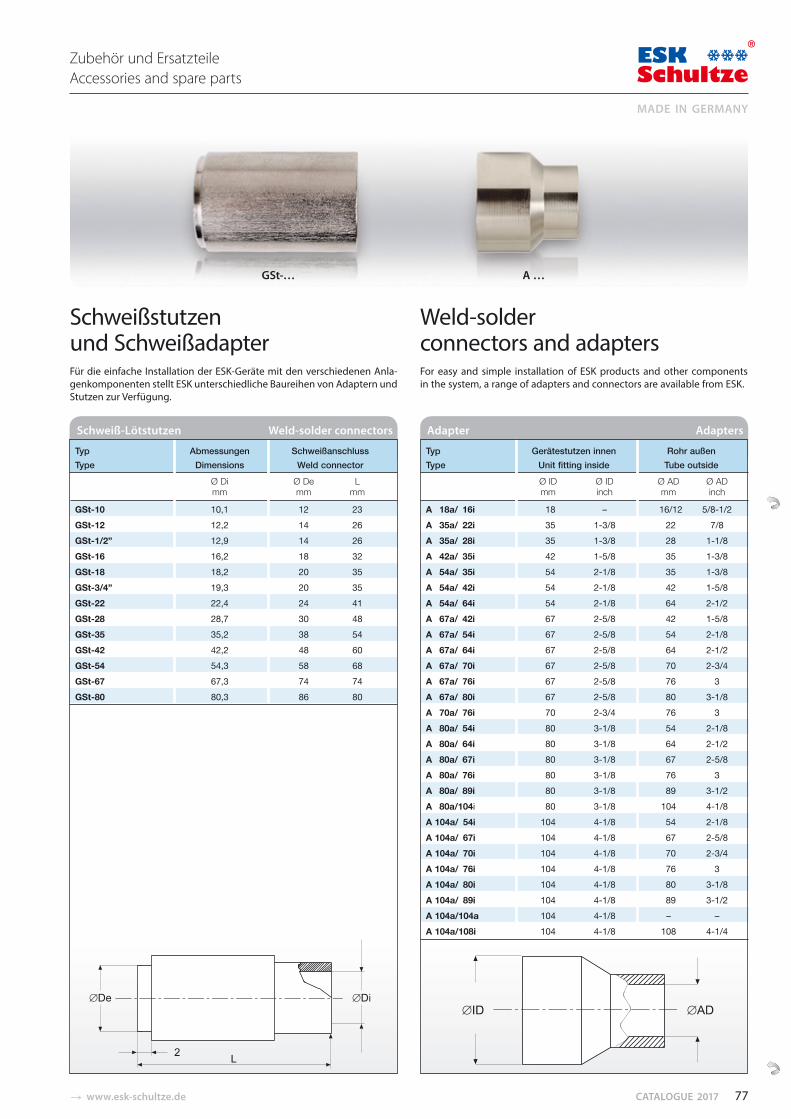
� www.esk-schultze.de CATALOGUE 2017
Adapter Adapters Schweiß-Lötstutzen Weld-solder connectors
GSt-… A …
Schweißstutzen und SchweißadapterFür die einfache Installation der ESK-Geräte mit den verschiedenen An la-gen komponenten stellt ESK unterschiedliche Baureihen von Adaptern und Stutzen zur Verfügung.
Weld-solder connectors and adapters For easy and simple installation of ESK products and other components in the system, a range of adapters and connectors are available from ESK.
Typ Gerätestutzen innen Rohr außen Type Unit fitting inside Tube outside
Ø ID Ø ID Ø AD Ø AD mm inch mm inch
A 18a/ 16i 18 – 16/12 5/8-1/2 A 35a/ 22i 35 1-3/8 22 7/8 A 35a/ 28i 35 1-3/8 28 1-1/8 A 42a/ 35i 42 1-5/8 35 1-3/8 A 54a/ 35i 54 2-1/8 35 1-3/8 A 54a/ 42i 54 2-1/8 42 1-5/8 A 54a/ 64i 54 2-1/8 64 2-1/2 A 67a/ 42i 67 2-5/8 42 1-5/8 A 67a/ 54i 67 2-5/8 54 2-1/8 A 67a/ 64i 67 2-5/8 64 2-1/2 A 67a/ 70i 67 2-5/8 70 2-3/4 A 67a/ 76i 67 2-5/8 76 3 A 67a/ 80i 67 2-5/8 80 3-1/8 A 70a/ 76i 70 2-3/4 76 3 A 80a/ 54i 80 3-1/8 54 2-1/8 A 80a/ 64i 80 3-1/8 64 2-1/2 A 80a/ 67i 80 3-1/8 67 2-5/8 A 80a/ 76i 80 3-1/8 76 3 A 80a/ 89i 80 3-1/8 89 3-1/2 A 80a/104i 80 3-1/8 104 4-1/8 A 104a/ 54i 104 4-1/8 54 2-1/8 A 104a/ 67i 104 4-1/8 67 2-5/8 A 104a/ 70i 104 4-1/8 70 2-3/4 A 104a/ 76i 104 4-1/8 76 3 A 104a/ 80i 104 4-1/8 80 3-1/8 A 104a/ 89i 104 4-1/8 89 3-1/2 A 104a/104a 104 4-1/8 – – A 104a/108i 104 4-1/8 108 4-1/4
Typ Abmessungen Schweißanschluss Type Dimensions Weld connector
Ø Di Ø De L mm mm mm
GSt-10 10,1 12 23 GSt-12 12,2 14 26 GSt-1/2” 12,9 14 26 GSt-16 16,2 18 32 GSt-18 18,2 20 35 GSt-3/4” 19,3 20 35 GSt-22 22,4 24 41 GSt-28 28,7 30 48 GSt-35 35,2 38 54 GSt-42 42,2 48 60 GSt-54 54,3 58 68 GSt-67 67,3 74 74 GSt-80 80,3 86 80
77
MADE IN GERMANY
Zubehör und ErsatzteileAccessories and spare parts
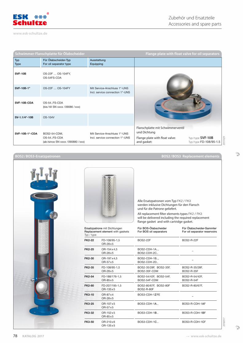
KATALOG 2017 � www.esk-schultze.de
Typ Für Ölabscheider-Typ Ausstattung Type For oil separator type Equipping
SVF-10B OS-22F … OS-104FY, OS-54FS-CDA
SVF-10B-1” OS-22F … OS-104FY Mit Service-Anschluss 1“-UNS Incl. service connection 1“-UNS
SVF-10B-CDA OS-54..FS-CDA (bis / till SN xxxx / 09086 / xxx) SV-1.1/4“-10B OS-104V
SVF-10B-1“-CDA BOS2-54-CDM, Mit Service-Anschluss 1“-UNS OS-54..FS-CDA Incl. service connection 1“-UNS (ab /since SN xxxx / 090880 / xxx)
BOS2 / BOS3-Ersatzpatronen BOS2 / BOS3 Replacement elements
Ersatzpatrone mit Dichtungen Für BOS-Ölabscheider Für Ölabscheider-Sammler Replacement element with gaskets For BOS oil separators For oil separator reservoirs Typ / type
FK2-22 FD-108/95-1,5 BOS 2-22F BOS2-R-22F OR-28 x 5
FK2-25 OR-154 x 4,5 BOS2-CDH-1A.., OR-28 x 5 BOS2-CDH-2C..
–
FK2-30 OR-197 x 4,5 BOS2-CDH-1B.., OR-57 x 5 BOS2-CDH-2D..
–
FK2-35 FD-108/95-1,5 BOS 2-35/28F, BOS 2-35F, BOS2-R-35/28F, OR-28 x 5 BOS 2-35F-CDM BOS2-R-35F
FK2-54 FD-188/176-1,5 BOS 2-54/42F, BOS 2-54F, BOS2-R-54/42F, OR-85 x 5 BOS 2-54F-CDM BOS2-R-54F
FK2-80 FD-207/195-1,5 BOS 2-80/67F, BOS 2-80F BOS2-R-80/67F, OR-135 x 5 BOS2-R-80F
FK3-10 OR-87 x 4 BOS 3-CDH-1Z FE OR-28 x 55
–
FK3-25 OR-107 x 5 BOS 3-CDH-1A .. BOS 3-R-CDH-1AF OR-57 x 5
FK3-32 OR-152 x 5 BOS 3-CDH-1B .. BOS 3-R-CDH-1BF OR-85 x 5
FK3-50 OR-210 x 6 BOS 3-CDH-1C .. BOS 3-R-CDH-1CF OR-135 x 5
Schwimmer-Flanschplatte für Ölabscheider Flange plate with float valve for oil separators
Alle Ersatzpatronen vom Typ FK2 / FK3werden inklusive Dichtungen für den Flansch und für die Patrone geliefert.
All replacement filter elements types FK2 / FK3 will be delivered including the required replacement flange gasket and with cartridge gasket.
Flanschplatte mit Schwimmerventil und Dichtung
Flange plate with float valve: Typ / type SVF-10B and gasket: Typ / type FD-108/95-1.5
2016
0517
2015
1029
78
www.esk-schultze.de
Zubehör und ErsatzteileAccessories and spare parts
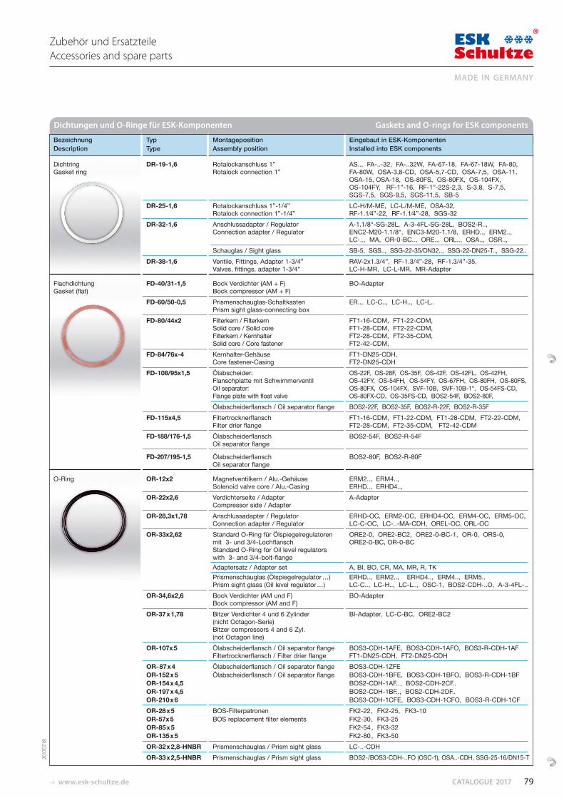
www.esk-schultze.de CATALOGUE 2017
Bezeichnung Typ Montageposition Eingebaut in ESK-Komponenten Description Type Assembly position Installed into ESK components
Dichtring DR-19-1,6 Rotalockanschluss 1” AS.., FA-..-32, FA-..32W, FA-67-18, FA-67-18W, FA-80, Gasket ring Rotalock connection 1” FA-80W, OSA-3,8-CD, OSA-5,7-CD, OSA-7,5, OSA-11,
OSA-15, OSA-18, OS-80FS, OS-80FX, OS-104FX, OS-104FY, RF-1”-16, RF-1”-22S-2,3, S-3,8, S-7,5, SGS-7,5, SGS-9,5, SGS-11,5, SB-5
DR-25-1,6 Rotalockanschluss 1”-1/4” LC-H/M-ME, LC-L/M-ME, OSA-32, Rotalock connection 1”-1/4” RF-1.1⁄4”-22, RF-1.1⁄4”-28, SGS-32
DR-32-1,6 Anschlussadapter / Regulator A-1.1/8“-SG-28L, A-3-4FL-SG-28L, BOS2-R..,Connection adapter / Regulator ENC2-M20-1.1/8“, ENC3-M20-1.1/8, ERHD.., ERM2..,
LC-.., MA, OR-0-BC.., ORE.., ORL.., OSA.., OSR..,Schauglas / Sight glass SB-5, SGS.., SSG-22-35/DN32.., SSG-22-DN25-T.., SSG-22..
DR-38-1,6 Ventile, Fittings, Adapter 1-3/4” RAV-2x1.3/4”, RF-1.3/4”-28, RF-1.3/4”-35, Valves, fittings, adapter 1-3/4” LC-H-MR, LC-L-MR, MR-Adapter
Flachdichtung FD-40/31-1,5 Bock Verdichter (AM + F) BO-Adapter Gasket (flat) Bock compressor (AM + F)
FD-60/50-0,5 Prismenschauglas-Schaltkasten ER.., LC-C.., LC-H.., LC-L..Prism sight glass-connecting box
FD-80/44x2 Filterkern / Filterkern FT1-16-CDM, FT1-22-CDM, Solid core / Solid core FT1-28-CDM, FT2-22-CDM, Filterkern / Kernhalter FT2-28-CDM, FT2-35-CDM,Solid core / Core fastener FT2-42-CDM,
FD-84/76x-4 Kernhalter-Gehäuse FT1-DN25-CDH,Core fastener-Casing FT2-DN25-CDH
FD-108/95x1,5 Ölabscheider: OS-22F, OS-28F, OS-35F, OS-42F, OS-42FL, OS-42FH, Flanschplatte mit Schwimmerventil OS-42FY, OS-54FH, OS-54FY, OS-67FH, OS-80FH, OS-80FS, Oil separator: OS-80FX, OS-104FX, SVF-10B, SVF-10B-1“, OS-54FS-CD, Flange plate with float valve OS-80FX-CD, OS-35FS-CD, BOS2-54F, BOS2-80F, Ölabscheiderflansch / Oil separator flange BOS2-22F, BOS2-35F, BOS2-R-22F, BOS2-R-35F
FD-115x4,5 Filtertrocknerflansch FT1-16-CDM, FT1-22-CDM, FT1-28-CDM, FT2-22-CDM, Filter drier flange FT2-28-CDM, FT2-35-CDM, FT2-42-CDM
FD-188/176-1,5 Ölabscheiderflansch BOS2-54F, BOS2-R-54FOil separator flange
FD-207/195-1,5 Ölabscheiderflansch BOS2-80F, BOS2-R-80FOil separator flange
O-Ring OR-12x2 Magnetventilkern / Alu.-Gehäuse ERM2.., ERM4.., Solenoid valve core / Alu.-Casing ERHD.., ERHD4..,
OR-22x2,6 Verdichterseite / Adapter A-AdapterCompressor side / Adapter
OR-28,3x1,78 Anschlussadapter / Regulator Connection adapter / Regulator
ERHD-OC, ERM2-OC, ERHD4-OC, ERM4-OC, ERM5-OC, LC-C-OC, LC-..-MA-CDH, OREL-OC, ORL-OC
OR-33x2,62 Standard O-Ring für Ölspiegelregulatoren ORE2-0, ORE2-BC2, ORE2-0-BC-1, OR-0, ORS-0,mit 3- und 3/4-Lochflansch ORE2-0-BC, OR-0-BCStandard O-Ring for Oil level regulators with 3- and 3/4-bolt-flangeAdaptersatz / Adapter set A, BI, BO, CR, MA, MR, R, TKPrismenschauglas (Ölspiegelregulator …) ERHD.., ERM2.., ERHD4.., ERM4.., ERM5..Prism sight glass (Oil level regulator …) LC-C.., LC-H.., LC-L.., OSC-1, BOS2-CDH-..O, A-3-4FL-..
OR-34,6x2,6 Bock Verdichter (AM und F) BO-AdapterBock compressor (AM and F)
OR-37 x 1,78 Bitzer Verdichter 4 und 6 Zylinder BI-Adapter, LC-C-BC, ORE2-BC2(nicht Octagon-Serie)Bitzer compressors 4 and 6 Zyl. (not Octagon line)
OR-107x 5 Ölabscheiderflansch / Oil separator flange BOS3-CDH-1AFE, BOS3-CDH-1AFO, BOS3-R-CDH-1AF Filtertrocknerflansch / Filter drier flange FT1-DN25-CDH, FT2-DN25-CDH
OR- 87 x 4 Ölabscheiderflansch / Oil separator flange BOS3-CDH-1ZFE OR-152 x 5 Ölabscheiderflansch / Oil separator flange BOS3-CDH-1BFE, BOS3-CDH-1BFO, BOS3-R-CDH-1BF OR-154 x 4,5 BOS2-CDH-1AF.. , BOS2-CDH-2CF.. OR-197 x 4,5 BOS2-CDH-1BF.., BOS2-CDH-2DF.. OR-210 x 6 BOS3-CDH-1CFE, BOS3-CDH-1CFO, BOS3-R-CDH-1CFOR-28 x 5 BOS-Filterpatronen FK2-22, FK2-25, FK3-10 OR-57x 5 BOS replacement filter elements FK2-30, FK3-25 OR-85 x 5 FK2-54 , FK3-32 OR-135 x 5 FK2-80 , FK3-50OR-32 x 2,8-HNBR Prismenschauglas / Prism sight glass LC-..-CDH OR-33 x 2,5-HNBR Prismenschauglas / Prism sight glass BOS2-/BOS3-CDH-..FO (OSC-1), OSA..-CDH, SSG-25-16/DN15-T
Dichtungen und O-Ringe für ESK-Komponenten Gaskets and O-rings for ESK components
2017
0718
79
MADE IN GERMANY
Zubehör und ErsatzteileAccessories and spare parts
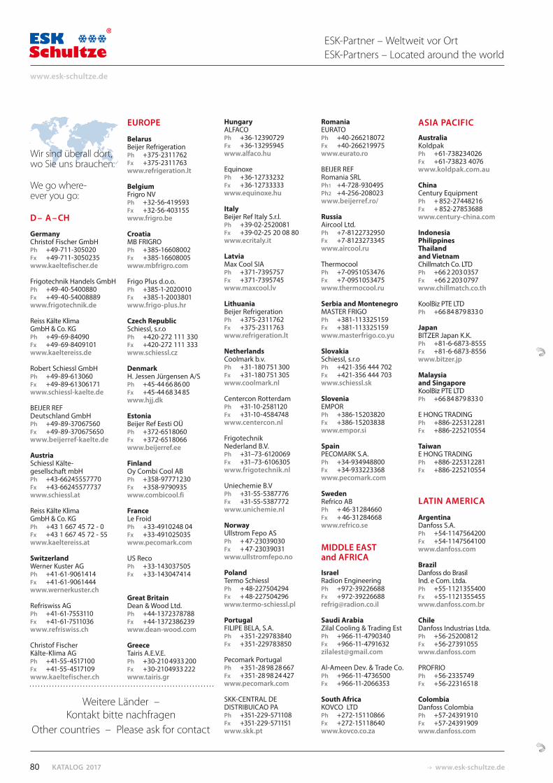
KATALOG 2017 www.esk-schultze.de
Wir sind überall dort, wo Sie uns brauchen:
We go where-ever you go:
D – A – CH
GermanyChristof Fischer GmbHPh +49-711-305020Fx +49-711-3050235www.kaeltefischer.de Frigotechnik Handels GmbHPh +49-40-5400880Fx +49-40-54008889www.frigotechnik.de
Reiss Kälte Klima GmbH & Co. KGPh +49-69-84090Fx +49-69-8409101www.kaeltereiss.de
Robert Schiessl GmbHPh +49-89-613060Fx +49-89-61306171www.schiessl-kaelte.de
BEIJER REF Deutschland GmbHPh +49-89-37067560Fx +49-89-370675650www.beijerref-kaelte.de
AustriaSchiessl Kälte-gesellschaft mbHPh +43-66245557770Fx +43-66245577737www.schiessl.at
Reiss Kälte Klima GmbH & Co. KGPh +43 1 667 45 72 - 0Fx +43 1 667 45 72 - 55www.kaeltereiss.at
SwitzerlandWerner Kuster AGPh +41-61-9061414Fx +41-61-9061444www.wernerkuster.ch
Refriswiss AGPh +41-61-7553110Fx +41-61-7511036www.refriswiss.ch
Christof Fischer Kälte-Klima AGPh +41-55-4517100Fx +41-55-4517109www.kaeltefischer.ch
EUROPE
BelarusBeijer RefrigerationPh +375-2311762Fx +375-2311763www.refrigeration.lt BelgiumFrigro NVPh +32-56-419593Fx +32-56-403155www.frigro.be
CroatiaMB FRIGROPh +385-16608002Fx +385-16608005www.mbfrigro.com
Frigo Plus d.o.o.Ph +385-1-2020010Fx +385-1-2003801www.frigo-plus.hr
Czech RepublicSchiessl, s.r.oPh +420-272 111 330Fx +420-272 111 333www.schiessl.cz
DenmarkH. Jessen Jürgensen A/SPh +45-44 66 86 00Fx +45-44 68 34 85www.hjj.dk
EstoniaBeijer Ref Eesti OÜPh +372-6518060Fx +372-6518066www.beijerref.ee
FinlandOy Combi Cool ABPh +358-97771230Fx +358-9790935www.combicool.fi
FranceLe FroidPh +33-4910248 04Fx +33-491025035www.pecomark.com
US RecoPh +33-143037505Fx +33-143047414
Great BritainDean & Wood Ltd.Ph +44-1372378788Fx +44-1372386239www.dean-wood.com
GreeceTairis A.E.V.E.Ph +30-210 4933 200Fx +30-2104933 222www.tairis.gr
HungaryALFACOPh +36-12390729Fx +36-13295945www.alfaco.hu
EquinoxePh +36-12733232Fx +36-12733333www.equinoxe.hu
ItalyBeijer Ref Italy S.r.l. Ph +39-02-2520081Fx +39-02-25 20 08 80www.ecritaly.it
LatviaMax Cool SIAPh +371-7395757Fx +371-7395745www.maxcool.lv
LithuaniaBeijer RefrigerationPh +375-2311762Fx +375-2311763www.refrigeration.lt
NetherlandsCoolmark b.v.Ph +31-180 751 300Fx +31-180 751 305www.coolmark.nl
Centercon RotterdamPh +31-10-2581120Fx +31-10-4584748www.centercon.nl
Frigotechnik Nederland B.V.Ph +31–73-6120069Fx +31–73-6106305www.frigotechnik.nl
Uniechemie B.VPh +31-55-5387776Fx +31-55-5387772www.unichemie.nl
NorwayUllstrom Fepo ASPh + 47-23039030Fx + 47-23039031www.ullstromfepo.no PolandTermo SchiesslPh + 48-227504294Fx + 48-227504296www.termo-schiessl.pl
Portugal FILIPE BELA, S.A.Ph +351-229783840Fx +351-229783850
Pecomark PortugalPh +351-28 98 28 667Fx +351-28 98 24 427www.pecomark.com
SKK-CENTRAL DE DISTRIBUICAO PAPh +351-229-571108Fx +351-229-571151www.skk.pt
RomaniaEURATOPh +40-266218072Fx +40-266219975www.eurato.ro
BEIJER REF Romania SRLPh1 +4-728-930495Ph2 +4-256-208023www.beijerref.ro/
RussiaAircool Ltd.Ph +7-8122732950Fx +7-8123273345www.aircool.ru
ThermocoolPh +7-0951053476Fx +7-0951053475www.thermocool.ru
Serbia and MontenegroMASTER FRIGOPh +381-113325159Fx +381-113325159www.masterfrigo.co.yu
Slovakia Schiessl, s.r.oPh +421-356 444 702Fx +421-356 444 703www.schiessl.sk
SloveniaEMPORPh +386-15203820Fx +386-15203838www.empor.si
SpainPECOMARK S.A.Ph +34-934948800Fx +34-933223368www.pecomark.com
SwedenRefrico ABPh + 46-31284660Fx + 46-31284668www.refrico.se
MIDDLE EAST and AFRICA
IsraelRadion EngineeringPh +972-39226688Fx [email protected]
Saudi ArabiaZilal Cooling & Trading EstPh +966-11-4790340Fx [email protected]
Al-Ameen Dev. & Trade Co.Ph +966-11-4736500Fx +966-11-2066353
South AfricaKOVCO LTDPh +272-15110866Fx +272-15118640www.kovco.co.za
ASIA PACIFIC
AustraliaKoldpakPh +61-738234026Fx +61-73823 4076www.koldpak.com.au
China Century EquipmentPh + 852-27448216Fx + 852-27853688www.century-china.com IndonesiaPhilippines Thailand and Vietnam Chillmatch Co. LTDPh +66 2 203 0357Fx +66 2 203 0797www.chillmatch.co.th
KoolBiz PTE LTDPh +66 84 879 833 0
Japan BITZER Japan K.K. Ph +81-6-6873-8555Fx +81-6-6873-8556www.bitzer.jp
Malaysia and SingaporeKoolBiz PTE LTDPh +66 84 879 833 0
E HONG TRADING Ph +886-225312281 Fx +886-225210554
TaiwanE HONG TRADING Ph +886-225312281 Fx +886-225210554
LATIN AMERICA
Argentina Danfoss S.A.Ph +54-1147564200Fx +54-1147564100www.danfoss.com
Brazil Danfoss do Brasil Ind. e Com. Ltda.Ph +55 -1121355400Fx +55- 1121355455www.danfoss.com.br
Chile Danfoss Industrias Ltda.Ph +56-25200812 Fx +56-27391055 www.danfoss.com
PROFRIO Ph +56-2335749Fx +56-22316518
ColombiaDanfoss Colombia Ph +57-24391910Fx +57-24391909 www.danfoss.com
ESK-Partner – Weltweit vor OrtESK-Partners – Located around the world
Weitere Länder – Kontakt bitte nachfragen
Other countries – Please ask for contact
80
www.esk-schultze.de


Quality Products · Made in Germany · Quality Products · Made in Germany · Quality Products · Made in Germany
Das neue Auslieferungslager The new warehouse
Seitenansicht Hauptgebäude Side view main building
Das neue Auslieferungslager The new warehouse
Seitenansicht Hauptgebäude Side view main building
Unsere Firmenzentrale am Stadtrand von BerlinOur company is based in Velten close-by Berlin.Unsere Firmenzentrale am Stadtrand von BerlinOur company is based in Velten close-by Berlin.
2017
.03-
02
ESK Schultze GmbH & Co. KGParkallee 8
D-16727 Velten
+ 49 (0) 3304 3903 0+ 49 (0) 3304 3903 [email protected]
www.esk-schultze.de
www.esk-schultze.dewww.esk-schultze.de