Embed Size (px)
Citation preview

Symbols
To allow quick and easy consultation, this manual uses graphic symbols to highlight situations in which maximum care is required, as well as practical advice or information.Pay attention to the meaning of the symbols since they serve to avoid repeating technical concepts or safety warnings throughout the text. The symbols should therefore be seen as real reminders. Please refer to this page whenever in doubt as to their meaning.
WarningFailure to follow these instructions might give raise to a dangerous situation and provoke severe personal injuries or even death.
CautionFailure to follow these instructions might cause damages to the vehicle and/or its components.
NotesUseful information on the procedure being described.
References
Parts highlighted in grey and with a numeric reference (Example 1 ) are the accessory to be installed and any assembly components supplied with the kit.
Parts with an alphabetic reference (Example A ) are the original components fitted on the vehicle.
Any right- or left-hand indication refers to the vehicle direction of travel.
General notes
WarningCarefully perform the operations on the following pages since they might negatively affect rider safety.
WarningCarefully perform the operations on the following pages since they might negatively affect rider safety.
NotesThe following documents are necessary for assembling the Kit:WORKSHOP MANUAL of your bike model.
NotesShould it be necessary to change any kit parts, please refer to the attached spare part table.
Simbologia
Per una lettura rapida e razionale sono stati impiegati simboli che evidenziano situazioni di massima attenzione, consigli pratici o semplici informazioni.Prestare molta attenzione al significato dei simboli, in quanto la loro funzione è quella di non dovere ripetere concetti tecnici o avvertenze di sicurezza. Sono da considerare, quindi, dei veri e propri “promemoria”.Consultare questa pagina ogni volta che sorgeranno dubbi sul loro significato.
AttenzioneLa non osservanza delle istruzioni riportate può creare una situazione di pericolo e causare gravi lesioni personali e anche la morte.
ImportanteIndica la possibilità di arrecare danno al veicolo e/o ai suoi componenti se le istruzioni riportate non vengono eseguite.
NoteFornisce utili informazioni sull’operazione in corso.
Riferimenti
I particolari evidenziati in grigio e riferimento numerico (Es. 1 ) rappresentano l’accessorio da installare e gli eventuali componenti di montaggio forniti a kit.
I particolari con riferimento alfabetico (Es. A ) rappresentano i componenti originali presenti sul motoveicolo.
Tutte le indicazioni destro o sinistro si riferiscono al senso di marcia del motociclo.
Avvertenze generali
AttenzioneLe operazioni riportate nelle pagine seguenti devono essere eseguite da un tecnico specializzato o da un’officina autorizzata DUCATI.
AttenzioneLe operazioni riportate nelle pagine seguenti se non eseguite a regola d’arte possono pregiudicare la sicurezza del pilota.
NoteDocumentazione necessaria per eseguire il montaggio del Kit è il MANUALE OFFICINA, relativo al modello di moto in vostro possesso.
NoteNel caso fosse necessaria la sostituzione di un componente del kit consultare la tavola ricambi allegata.
Kit plexiglass SportSport plexiglass kit
1
XDiavel ISTR - 756 / 00 97180351A

Pos. Denominazione Description
1 Cavallotto superiore destro Upper RH U-bolt
2 Cavallotto superiore sinistro Upper LH U-bolt
3 Passacavo Cable ring
4 Parabrezza Windscreen
5 Vite speciale M5 Special M5 screw
2 ISTR 756 / 00
5 3
1 25 3
5 35
4
3

Removing the original components
Upper RH U-bolt removal
Loosen no. 2 screws (A1) and remove upper RH U-bolt (A).Keep the no.2 screws (A1).
Upper LH U-bolt removal
Duly support the handlebar (C), loosen the no. 2 screws (B1) and remove the upper LH U-bolt (B).Keep the no.2 screws (B1).
Smontaggio componenti originali
Smontaggio cavallotto superiore destro
Svitare le n.2 viti (A1) e rimuovere il cavallotto superiore destro (A).Recuperare le n.2 viti (A1).
Smontaggio cavallotto superiore sinistro
Sostenendo adeguatamente il manubrio (C), svitare le n.2 viti (B1) e rimuovere il cavallotto superiore sinistro (B).Recuperare le n.2 viti (B1).
3ISTR 756 / 00
A1 A B1 B
C

4 ISTR 756 / 00
XA1 1
B1
2
C
1 2
D
E
C1
1
2
3
4
25 Nm ± 10%
25 Nm ± 10%
A1
3 Nm ± 10%
5 3
3 Nm ± 10%
5 3
3 Nm ± 10%
5 35
3
4
3 Nm ± 10%

Kit installation
CautionCheck that all components are clean and in perfect condition before installation.Adopt any precaution necessary to avoid damages to any part of the motorcycle you are working on.
Upper U-bolt assembly
Smear the thread and underhead of no. 2 original screws (A1) with GADIUS S2 V220 AD 2 grease.Position the upper RH U-bolt (1) on the lower U-bolt (D) and start no. 2 original screws (A1) without tightening them.Smear the thread and underhead of no. 2 original screws (B1) with GADIUS S2 V220 AD 2 grease.Position the upper LH U-bolt (2) on the lower U-bolt (E) and start no. 2 original screws (B1).Adjust the handlebar (C) by using the engraved points (C1) on the handlebar as a reference, as indicated in box (X).Tighten no. 4 screws (A1) and (B1) to the specified torque, following the sequence 1-2-3-4-1-2.
CautionFor a correct assembly of upper U-bolts (1) and (2) the tightening sequence must be followed.
Headlight fairing assembly
Pre-assemble no. 4 grommets (3) on headlight fairing (4) with alcohol or soapy water.Position headlight fairing (4) on the U-bolts (1) and (2) and start no. 4 special screws (5).Slightly tighten the no. 4 special screws (5) to avoid squeezing the grommets.
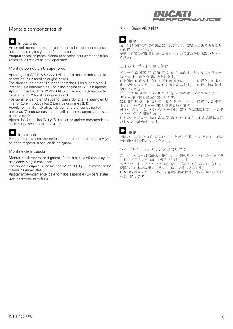
Montaggio componenti kit
ImportanteVerificare, prima del montaggio, che tutti i componenti risultino puliti e in perfetto stato. Adottare tutte le precauzioni necessarie per evitare di danneggiare qualsiasi parte nella quale ci si trova ad operare.
Montaggio cavallotti superiori
Applicare grasso GADIUS S2 V220 AD 2 su filetto e sottotesta delle n.2 viti originali (A1).Posizionare il cavallotto superiore destro (1) sul cavallotto inferiore (D) e impuntare le n.2 viti originali (A1), senza serrarle.Applicare grasso GADIUS S2 V220 AD 2 su filetto e sottotesta delle n.2 viti originali (B1).Posizionare il cavallotto superiore sinistro (2) sul cavallotto inferiore (E) e impuntare le n.2 viti originali (B1).Regolare il manubrio (C) utilizzando come riferimento le bulinature (C1) poste sul manubrio stesso, come indicato nel riquadro (X).Serrare le n.4 viti (A1) e (B1) alla coppia indicata, applicando la sequenza 1-2-3-4-1-2.
ImportantePer un corretto montaggio dei cavallotti superiori (1) e (2) occorre rispettare la sequenza di serraggio.
Montaggio cupolino
Premontare i n.4 gommini (3) sul cupolino (4) aiutandosi con alcool o acqua saponata.Posizionare il cupolino (4) sui cavallotti (1) e (2), impuntare le n.4 viti speciali (5).Serrare moderatamente le n.4 viti speciali (5) per evitare lo schiacciamento dei gommini.
5 ISTR 756 / 00

NOTE / NOTES
1 P/N 商品名
2 P/N 商品名
3 P/N 商品名
4 P/N 商品名
5 P/N 商品名
ご注文商品
レース専用部品 ご注文書DUCATI PERFORMANCE accessories
モデル名
ご注文日
販売日 年 月 日
1. 上記ご記入の上、弊社アフターセールス部までFAXしてください。FAX:03-6692-1317
お客様ご記入欄
私は上記レース専用部品を下記車両に装着し、サーキット走行のみに利用し、一般公道には利用しません。
販売店署名
販売店様へお願い
車台番号 ZDM
お客様署名
ドゥカティ正規ネットワーク店記入欄
お客様に上記レース専用部品を販売し、レース専用部品のご利用方法を説明いたしました。
1. 上記ご記入の上、弊社アフターセールス部までFAXしてください。FAX:03-6692-13172. 取り付け車両1台に1枚でご使用ください。
ISTR 756 / 00

Symbole
Zum schnellen und übersichtlichen Lesen werden Symbole verwendet, die außerordentlich wichtige Situationen, praktische Ratschläge oder auch nur einfache Informationen hervorheben. Der Bedeutung dieser Symbole ist besondere Aufmerksamkeit zu schenken, da sich hierdurch das ständige Wiederholen von technischen Konzepten oder Sicherheitshinweisen erübrigt. Sie stellen daher regelrechte „Merker“ dar. Diese Seite ist immer dann zur Hand zu nehmen, wenn Zweifel über die Bedeutung eines Symbols bestehen sollten.
AchtungEine Nichtbeachtung der hier wiedergegebenen Anweisungen kann Gefahrensituationen schaffen und zu schweren Verletzungen und auch zum Tod führen.
WichtigWeist darauf hin, dass bei Nichteinhaltung der hier wiedergegebenen Anweisungen die Möglichkeit für Schäden am Fahrzeug und/oder seiner Komponenten besteht.
HinweisÜbermittelt nützliche Informationen zum betreffenden Arbeitseingriff.
Bezugsangaben
Die grau gekennzeichneten Bestandteile mit numerischem Bezug (Bsp. 1 ) geben das zu installierende Bestandteil und die eventuellen, im Kit enthaltenen Montagekomponenten wieder.
Die Bestandteile mit alphabetischem Bezug (Bsp. A ) geben die Original-Bestandteile wieder, die am Motorrad verbaut wurden.
Alle Angaben wie „rechts” oder „links” beziehen sich auf die Fahrtrichtung des Motorrads.
Allgemeine Warnhinweise
AchtungWerden die auf den folgenden Seiten beschriebenen Arbeitsmaßnahmen nicht fachgerecht ausgeführt, kann sich dies auf die Sicherheit des Fahrers auswirken.
AchtungWerden die auf den folgenden Seiten beschriebenen Arbeitsmaßnahmen nicht fachgerecht ausgeführt, kann sich dies auf die Sicherheit des Fahrers auswirken.
HinweisFür die Montage des Kits sind folgende Unterlagen erforderlich: WERKSTATTHANDBUCH, des sich in Ihrem Besitz befindlichen Motorrads.
HinweisSollte sich der Austausch eines Bestandteils des Kits als erforderlich erweisen, ist dazu Bezug auf die beiliegende Ersatzteiltafel zu nehmen.
Symboles
Pour faciliter la consultation de ce manuel, des symboles signalent des situations exigeant le maximum d'attention, des conseils pratiques ou de simples informations. Lire attentivement la signification de ces symboles car ils renvoient à des concepts techniques ou des consignes de sécurité de la plus grande importance. Ils doivent être considérés comme de véritables « aide-mémoire ». Toujours consulter cette page en cas de doute concernant leur signification.
AttentionLa non-observance des instructions reportées ci-dessous peut créer une situation dangereuse et provoquer de graves lésions personnelles voire la mort.
ImportantIndique la possibilité d'endommager le véhicule et/ou ses composants si les instructions reportées ci-dessous ne sont pas suivies.
RemarquesFournit des informations utiles sur l'opération en cours.
Références
Les pièces surlignées en gris et la référence numérique (Ex. 1 ) représentent l'accessoire à installer et les composants de montage éventuels fournis en kit.
Les pièces avec référence alphabétique (Ex. A ) représentent les composants d'origine présents sur le motocycle.
Toutes les indications droite ou gauche se réfèrent au sens de marche la moto.
Avertissements généraux
AttentionLes opérations indiquées dans les pages suivantes, au cas où elles ne seraient pas effectuées selon les règles de l'art pourraient compromettre la sécurité du pilote.
AttentionLes opérations indiquées dans les pages suivantes, au cas où elles ne seraient pas effectuées selon les règles de l'art pourraient compromettre la sécurité du pilote.
RemarquesLa documentation nécessaire pour effectuer la pose du Kit est le : MANUEL D'ATELIER, relatif au modèle de moto en votre possession.
RemarquesAu cas où il serait nécessaire d'effectuer le remplacement d'un composant du kit, il faudra consulter la planche relative aux pièces détachées ci-jointe.
Kit pare-brise Sport Kit Sport-Plexiglas
1
XDiavel ISTR - 756 / 00 97180351A

Pos. Designation Bezeichnung
1 Étrier de jonction supérieur droit Obere rechte Klemmfaust
2 Étrier de jonction supérieur gauche Obere linke Klemmfaust
3 Passe-fil Kabelführung
4 Pare-brise Fahrtwindschutz
5 Vis spéciale M5 Spezialschraube M5
2 ISTR 756 / 00
5 3
1 25 3
5 35
4
3

Ausbau der Original-Bestandteile
Abnahme der oberen rechten Klemmfaust
Die 2 Schrauben (A1) lösen, dann die obere rechte Klemmfaust (A) abnehmen.Die 2 Schrauben (A1) aufnehmen.
Abnahme der oberen linken Klemmfaust
Den Lenker (C) angemessen abstützen, die 2 Schrauben (B1) lösen und die obere linke Klemmfaust (B) abnehmen.Die 2 Schrauben (B1) aufnehmen.
Dépose composants d'origine
Dépose étrier de jonction supérieur droit
Desserrer les 2 vis (A1) et déposer l'étrier de jonction supérieur droit (A).Récupérer les 2 vis (A1).
Dépose étrier de jonction supérieur gauche
En soutenant de manière appropriée le guidon (C), desserrer les 2 vis (B1) et déposer l'étrier de jonction supérieur gauche (B).Récupérer les 2 vis (B1).
3ISTR 756 / 00
A1 A B1 B
C

Montage der Komponenten des Kits
WichtigVor der Montage überprüfen, dass sich alle Komponenten im sauberen und perfekten Zustand befinden.Alle erforderlichen Vorsichtsmaßnahmen treffen, um eine Beschädigung der Oberflächen der Komponenten, die vom Eingriff betroffen sind, zu vermeiden.
Pose composants kit
ImportantVérifier, avant la pose, que tous les composants sont propres et en parfait état.Adopter toutes les précautions nécessaires pour éviter d'endommager la surface externe des composants où on opère.
4 ISTR 756 / 00
XA1 1
B1
2
C
1 2
D
E
C1
1
2
3
4
25 Nm ± 10%
25 Nm ± 10%
A1
3 Nm ± 10%
5 3
3 Nm ± 10%
5 3
3 Nm ± 10%
5 35
3
4
3 Nm ± 10%

Montage der Bestandteile des Kits
WichtigVor der Montage überprüfen, dass alle Bestandteile sauber sind und sich im perfekten Zustand befinden.Alle erforderlichen Vorsichtsmaßnahmen treffen, um eine Beschädigung der Bereiche, in denen man arbeitet, zu vermeiden.
Montage obere Klemmfäuste
Das Fett GADIUS S2 V220 AD 2 auf das Gewinde und unter dem Kopf der 2 Original-Schrauben (A1) auftragen.Die obere rechte Klemmfaust (1) auf der unteren Klemmfaust (D) anordnen und die 2 Original-Schrauben (A1) ansetzen, ohne sie dabei anzuziehen.Das Fett GADIUS S2 V220 AD 2 auf das Gewinde und unter dem Kopf der 2 Original-Schrauben (B1) auftragen.Die obere linke Klemmfaust (2) auf der unteren Klemmfaust (E) anordnen und die 2 Original-Schrauben (B1) ansetzen.Den Lenker (C) einstellen, dabei die Markierungspunkte (C1) am Lenker als Bezug verwenden; siehe Detailausschnitt (X).Die 4 Schrauben (A1) und (B1) 1-2-3-4-1-2 mit angegebenem Anzugsmoment in der Sequenz anziehen.
WichtigFür eine korrekte Montage der oberen Klemmfäuste (1) und (2) muss die Anzugssequenz eingehalten werden.
Montage der Cockpitverkleidung
Die 4 Gummielemente (3) an der Cockpitverkleidung (4) unter Zuhilfenahme von Alkohol oder Seifenwasser vormontieren.Die Cockpitverkleidung (4) an den Klemmfäusten (1) und (2) anordnen und die 4 Spezialschrauben (5) ansetzen.Die 4 Spezialschrauben (5) mit mäßiger Kraft anziehen, um die Gummielemente nicht einzudrücken.
Pose des composants kit
ImportantAvant la pose, vérifier que tous les composants sont propres et en bon état.Prendre toutes les précautions nécessaires pour éviter d'endommager toute partie dans laquelle on intervient.
Pose étriers de jonction supérieurs
Appliquer de la Graisse GADUS S2 V220 AD 2 sur le filet et le dessous des têtes des 2 vis d'origine (A1).Positionner l'étrier de jonction supérieur droit (1) sur l'étrier de jonction inférieur (D) et présenter les 2 vis d'origine (A1), sans les serrer.Appliquer de la Graisse GADUS S2 V220 AD 2 sur le filet et le dessous des têtes des 2 vis d'origine (B1).Positionner l'étrier de jonction supérieur gauche (2) sur l'étrier de jonction inférieur (E) et présenter les 2 vis d'origine (B1).Régler le guidon (C) en utilisant comme repère les burinages (C1) situés sur ce dernier, comme indiqué dans l'encadré (X).Serrer les 4 vis (A1) et (B1) au couple prescrit suivant la séquence 1-2-3-4-1-2.
ImportantPour une pose correcte des étriers de jonction supérieurs (1) et (2), il faut respecter la séquence de serrage.
Pose de la bulle
Pré-installer les 4 plots caoutchouc (3) sur la bulle (4) en utilisant de l'alcool ou de l'eau savonneuse.Positionner la bulle (4) sur les étriers de jonction (1) et (2) et présenter les 4 vis spéciales (5).Serrer modérément les 4 vis spéciales (5) pour éviter d'écraser les plots en caoutchouc.
5 ISTR 756 / 00

REMARQUES / HINWEIS
1 P/N 商品名
2 P/N 商品名
3 P/N 商品名
4 P/N 商品名
5 P/N 商品名
ご注文商品
レース専用部品 ご注文書DUCATI PERFORMANCE accessories
モデル名
ご注文日
販売日 年 月 日
1. 上記ご記入の上、弊社アフターセールス部までFAXしてください。FAX:03-6692-1317
お客様ご記入欄
私は上記レース専用部品を下記車両に装着し、サーキット走行のみに利用し、一般公道には利用しません。
販売店署名
販売店様へお願い
車台番号 ZDM
お客様署名
ドゥカティ正規ネットワーク店記入欄
お客様に上記レース専用部品を販売し、レース専用部品のご利用方法を説明いたしました。
1. 上記ご記入の上、弊社アフターセールス部までFAXしてください。FAX:03-6692-13172. 取り付け車両1台に1枚でご使用ください。
ISTR 756 / 00

Símbolos
Para uma leitura rápida e racional, foram utilizados símbolos que evidenciam situações de máxima atenção, conselhos práticos ou simples informações. Preste muita atenção ao significado dos símbolos, pois a sua função é a de evitar a repetição de conceitos técnicos ou de avisos de segurança. Portanto, os símbolos devem ser considerados como verdadeiros "lembretes". Consulte esta página sempre que tiver dúvidas acerca do seu significado.
AtençãoO não cumprimento das instruções mostradas pode criar uma situação de perigo e causar graves lesões pessois e até mesmo a morte.
ImportanteIndica a possibilidade de causar danos ao veículo e/ou aos seus componentes se as instruções mostradas não forem executadas.
NotasFornece informações úteis sobre a operação em curso.
Referências
Os detalhes evidenciados em cinza e com referência numérica (Ex. A ) representam o acessório a ser instalado e os eventuais componentes de montagem fornecidos como kit.
Os detalhes com referência alfabética (Ex. A ) representam os componentes originais presentesna moto.
Todas as indicações direita ou esquerda, referem-se ao sentido de marcha da moto.
Advertências gerais
AtençãoAs operações mostradas nas páginas a seguir, se não forem executadas com boa técnica, podem prejudicar a segurança do condutor.
AtençãoAs operações mostradas nas páginas a seguir, se não forem executadas com boa técnica, podem prejudicar a segurança do condutor.
NotasDocumentação necessária para executar a montagem do Conjunto: MANUAL DE OFICINA, relativo ao modelo de moto em sua posse.
NotasCaso seja necessária a substituição de um componente do conjunto, consulte o quadro de peças de reposição em anexo.
Conjunto de plexiglas SportSport plexiglass kit
Symbols
To allow quick and easy consultation, this manual uses graphic symbols to highlight situations in which maximum care is required, as well as practical advice or information.Pay attention to the meaning of the symbols since they serve to avoid repeating technical concepts or safety warnings throughout the text. The symbols should therefore be seen as real reminders. Please refer to this page whenever in doubt as to their meaning.
WarningFailure to follow these instructions might give raise to a dangerous situation and provoke severe personal injuries or even death.
CautionFailure to follow these instructions might cause damages to the vehicle and/or its components.
NotesUseful information on the procedure being described.
References
Parts highlighted in grey and with a numeric reference (Example 1 ) are the accessory to be installed and any assembly components supplied with the kit.
Parts with an alphabetic reference (Example A ) are the original components fitted on the vehicle.
Any right- or left-hand indication refers to the vehicle direction of travel.
General notes
WarningCarefully perform the operations on the following pages since they might negatively affect rider safety.
WarningCarefully perform the operations on the following pages since they might negatively affect rider safety.
NotesThe following documents are necessary for assembling the Kit:WORKSHOP MANUAL of your bike model.
NotesShould it be necessary to change any kit parts, please refer to the attached spare part table.
1
XDiavel ISTR - 756 / 00 97180351A

Pos. Descrição Description
1 Braçadeira superior direita Upper RH U-bolt
2 Braçadeira superior esquerda Upper LH U-bolt
3 Passa-cabo Cable ring
4 Para-brisas Windscreen
5 Parafuso especial M5 Special M5 screw
2 ISTR 756 / 00
5 3
1 25 3
5 35
4
3

Desmontagem dos componentes originais
Desmontagem da braçadeira superior direita
Desatarraxe os 2 parafusos (A1) e remova a braçadeira superior direita (A).Guarde os 2 parafusos (A1).
Desmontagem da braçadeira superior esquerda
Sustentando adequadamente o guiador (C), desatarraxe os 2 parafusos (B1) e remova a braçadeira superior esquerda (B).Recupere os 2 parafusos (B1).
Removing the original components
Upper RH U-bolt removal
Loosen no. 2 screws (A1) and remove upper RH U-bolt (A).Keep the no.2 screws (A1).
Upper LH U-bolt removal
Duly support the handlebar (C), loosen the no. 2 screws (B1) and remove the upper LH U-bolt (B).Keep the no.2 screws (B1).
3ISTR 756 / 00
A1 A B1 B
C

Montagem dos componentes
ImportanteVerifique, antes da montagem, se todos os componentes estão limpos e em perfeito estado.Adote todas as precauções necessárias para evitar danificar qualquer peça com a qual deve trabalhar.
4 ISTR 756 / 00
XA1 1
B1
2
C
1 2
D
E
C1
1
2
3
4
25 Nm ± 10%
25 Nm ± 10%
A1
3 Nm ± 10%
5 3
3 Nm ± 10%
5 3
3 Nm ± 10%
5 35
3
4
3 Nm ± 10%

Montagem dos componentes
ImportanteVerifique, antes da montagem, se todos os componentes estão limpos e em perfeito estado.Adote todas as precauções necessárias para evitar danificar qualquer peça com a qual deve trabalhar.
Montagem das braçadeiras superiores
Aplique massa GADIUS S2 V220 AD 2 na rosca e na parte inferior da cabeça dos 2 parafusos originais (A1).Posicione a braçadeira superior direita (1) na braçadeira inferior (D) e encoste os 2 parafusos originais (A1), sem apertá-los.Aplique massa GADIUS S2 V220 AD 2 na rosca e na parte inferior da cabeça dos 2 parafusos originais (B1).Posicione a braçadeira superior esquerda (2) na braçadeira inferior (E) e encoste os 2 parafusos originais (B1).Regule o guiador (C), utilizando como referência as marcas (C1) localizadas no próprio guiador, como indicado no quadro (X).Aperte os 4 parafusos (A1) e (B1) ao binário indicado, aplicando a sequência 1-2-3-4-1-2.
ImportantePara uma correta montagem das braçadeiras superiores (1) e (2), é necessário respeitar a sequência de aperto.
Montagem da cúpula
Pré-monte as 4 borrachas (3) na cúpula (4), ajudando-se com álcool ou água com sabão.Posicione a cúpula (4) nas braçadeiras (1) e (2), encoste os 4 parafusos especiais (5).Aperte com moderação os 4 parafusos especiais (5), a fim de evitar o esmagamento das borrachas.
Kit installation
CautionCheck that all components are clean and in perfect condition before installation.Adopt any precaution necessary to avoid damages to any part of the motorcycle you are working on.
Upper U-bolt assembly
Smear the thread and underhead of no. 2 original screws (A1) with GADIUS S2 V220 AD 2 grease.Position the upper RH U-bolt (1) on the lower U-bolt (D) and start no. 2 original screws (A1) without tightening them.Smear the thread and underhead of no. 2 original screws (B1) with GADIUS S2 V220 AD 2 grease.Position the upper LH U-bolt (2) on the lower U-bolt (E) and start no. 2 original screws (B1).Adjust the handlebar (C) by using the engraved points (C1) on the handlebar as a reference, as indicated in box (X).Tighten no. 4 screws (A1) and (B1) to the specified torque, following the sequence 1-2-3-4-1-2.
CautionFor a correct assembly of upper U-bolts (1) and (2) the tightening sequence must be followed.
Headlight fairing assembly
Pre-assemble no. 4 grommets (3) on headlight fairing (4) with alcohol or soapy water.Position headlight fairing (4) on the U-bolts (1) and (2) and start no. 4 special screws (5).Slightly tighten the no. 4 special screws (5) to avoid squeezing the grommets.
5 ISTR 756 / 00

NOTAS / NOTES
1 P/N 商品名
2 P/N 商品名
3 P/N 商品名
4 P/N 商品名
5 P/N 商品名
ご注文商品
レース専用部品 ご注文書DUCATI PERFORMANCE accessories
モデル名
ご注文日
販売日 年 月 日
1. 上記ご記入の上、弊社アフターセールス部までFAXしてください。FAX:03-6692-1317
お客様ご記入欄
私は上記レース専用部品を下記車両に装着し、サーキット走行のみに利用し、一般公道には利用しません。
販売店署名
販売店様へお願い
車台番号 ZDM
お客様署名
ドゥカティ正規ネットワーク店記入欄
お客様に上記レース専用部品を販売し、レース専用部品のご利用方法を説明いたしました。
1. 上記ご記入の上、弊社アフターセールス部までFAXしてください。FAX:03-6692-13172. 取り付け車両1台に1枚でご使用ください。
ISTR 756 / 00

シンボル
素早くかつ合理的に読み進めることができるように、本マニュアルではいくつかのシンボルを導入し、最大限の注意を払う必要がある状況や、推奨事項、または一般情報を明確にしてあります。技術的概念や安全に関する警告を繰り返し記載する必要がないように機能しているので、各シンボルの意味に十分注意してください。シンボルは、実際上の“覚え書き” であると考えてください。シンボルなどの意味がわからなくなったり疑問に思う場合は、必ずこのページで調べるようにしてください。
注記この説明書に従わずに使用すると危険な状況を招き、重大なけが、あるいは死をももたらす原因となることがあります。
重要この説明書に従わずに使用すると、車体及び/ 又はその部品に損害を招く可能性があります
参考操作中の内容に関する有用な情報を掲載しています。
参照
灰色で表示する部品、および参照番号 (Es. 1 ) で表示する部品
は、キットに付属する取り付け部品および組み立て部品を示しま
す。
参照アルファベット (Es. A ) で表示する部品は、車両に付属す
るオリジナル部品を示します。
すべての右及び左の指示は車体の進行方向を向いたものです。
一般警告事項
警告以下のページに記載されている作業が規定通りに実施されないと、ライダーの安全性を脅かすおそれがあります。
警告以下のページに記載されている作業が規定通りに実施されないと、ライダーの安全性を脅かすおそれがあります。
参考キットの取り付けに必要な資料:お手持ちの車両モデルに対応するワークショップマニュアル 。
参考キットの部品を交換する必要がある場合は、添付のスペアパーツ表を参照してください。
Símbolos
Para una lectura rápida y racional se han empleado símbolos que evidencian situaciones de máxima atención, consejos prácticos o simples informaciones. Prestar mucha atención al significado de los símbolos porque su función consiste en omitir la repetición de conceptos técnicos o advertencias de seguridad. Los símbolos deben considerarse como verdaderos “apuntes”. Consultar esta página cada vez que se tengan dudas sobre su significado.
AtenciónEl incumplimiento de las instrucciones indicadas puede crear una situación de peligro y ocasionar graves lesiones e incluso la muerte.
ImportanteIndica la posibilidad de provocar un daño al vehículo y/o a sus componentes si no se siguen las instrucciones indicadas.
NotasSuministra útiles informaciones sobre la operación en curso.
Referencias
Las partes resaltadas en gris y la referencia numérica (Por ej. 1 ) representan el accesorio que se debe instalar y los eventuales componentes de montaje suministrados en el kit.
Las partes con referencia alfabética (Por ej. A ) representan los componentes originales presentes en la motocicleta.
Todas las indicaciones derecha o izquierda se refieren al sentido de marcha de la motocicleta.
Advertencias generales
AtenciónLas operaciones descritas en las siguientes páginas deben realizarse correctamente para no perjudicar la seguridad del piloto.
AtenciónLas operaciones descritas en las siguientes páginas deben realizarse correctamente para no perjudicar la seguridad del piloto.
NotasLa documentación necesaria para realizar el montaje del Kit es el: MANUAL DE TALLER, relativo al modelo de moto en vuestro poder.
NotasSi fuera necesario sustituir un componente del kit, consultar la tabla de recambios adjunta.
Kit plexiglás SportSport プレキシガラスキット
1
XDiavel ISTR - 756 / 00 97180351A

Pos. Denominacion 説明
1 Perno en U superior derecho 右上側の U ボルト
2 Perno en U superior izquierdo 左上側の U ボルト
3 Pasacable ケーブルガイド
4 Parabrisas ウィンドスクリーン
5 Tornillo especial M5 専用スクリュー M5
2 ISTR 756 / 00
5 3
1 25 3
5 35
4
3

オリジナル部品の取り外し
右上側の U ボルトの取り外し
2 本のスクリュー (A1) を緩めて外し、右上側の U ボルト (A) を取り外します。2 本のスクリュー (A1) を回収します。
左上側の U ボルトの取り外し
ハンドルバー (C) を適切に支え、2 本のスクリュー (B1) を緩めて外し、左上側の U ボルト (B) を取り外します。2 本のスクリュー (B1) を回収します。
Desmontaje componentes originales
Desmontaje perno en U superior derecho
Desatornillar los 2 tornillos (A1) y quitar el perno en U superior derecho (A).Recuperar los 2 tornillos (A1).
Desmontaje perno en U superior izquierdo
Sosteniendo el manillar (C) de manera adecuada, desatornillar los 2 tornillos (B1) y quitar el perno en U superior izquierdo (B).Recuperar los 2 tornillos (B1).
3ISTR 756 / 00
A1 A B1 B
C

キット部品の取り付け
重要取り付け前にすべての部品に汚れがなく、完璧な状態であることを確認します。作業する部品の外側表面を傷つけないために、必要な予防措置を取ってください
Montaje componentes kit
ImportanteControlar, antes del montaje, que todos los componentes se encuentren limpios y en perfecto estado.Adoptar todas las precauciones necesarias para evitar daños en la superficie exterior de los componentes donde se debe operar.
4 ISTR 756 / 00
XA1 1
B1
2
C
1 2
D
E
C1
1
2
3
4
25 Nm ± 10%
25 Nm ± 10%
A1
3 Nm ± 10%
5 3
3 Nm ± 10%
5 3
3 Nm ± 10%
5 35
3
4
3 Nm ± 10%
キット部品の取り付け
重要取り付けの前に全ての部品に汚れがなく、完璧な状態であることを確認してください。作業する部分が破損しないようすべての必要な予防措置をとってください。
上側の U ボルトの取り付け
グリース GADIUS S2 V220 AD 2 を 2 本のオリジナルスクリュー (A1) のネジ山と座面に塗布します。右上側の U ボルト (1) を下側の U ボルト (D) に置き、2 本のオリジナルスクリュー (A1) を差し込みます。この時、締め付けないでください。グリース GADIUS S2 V220 AD 2 を 2 本のオリジナルスクリュー (B1) のネジ山と座面に塗布します。左上側の U ボルト (2) を下側の U ボルト (E) に置き、2 本のオリジナルスクリュー (B1) を差し込みます。図 (X) のように、ハンドルバーの印 (C1) を基準にして、ハンドルバー (C) を調整します。4 本のスクリュー (A1) および (B1) を 1-2-3-4-1-2 の順に規定のトルクで締め付けます。
重要上側の U ボルト (1) および (2) を正しく取り付けるため、締め付け順序は必ず守ってください。
ヘッドライトフェアリングの取り付け
アルコールまたは石鹸水を使用し、4 個のラバー (3) をヘッドライトフェアリング (4) に仮取り付けします。ヘッドライトフェアリング (4) を U ボルト (1) および (2) に配置し、4 本の専用スクリュー (5) を差し込みます。4 本の専用スクリュー (5) を適度に締め付け、ラバーがつぶれないようにします。
Montaje componentes kit
ImportanteAntes del montaje, comprobar que todos los componentes se encuentren limpios y en perfecto estado.Adoptar todas las precauciones necesarias para evitar dañar las zonas en las cuales se está operando.
Montaje pernos en U superiores
Aplicar grasa GADIUS S2 V220 AD 2 en la rosca y debajo de la cabeza de los 2 tornillos originales (A1).Posicionar el perno en U superior derecho (1) en el perno en U inferior (D) e introducir los 2 tornillos originales (A1) sin apretar.Aplicar grasa GADIUS S2 V220 AD 2 en la rosca y debajo de la cabeza de los 2 tornillos originales (B1).Posicionar el perno en U superior izquierdo (2) en el perno en U inferior (E) e introducir los 2 tornillos originales (B1).Regular el manillar (C) utilizando como referencia las partes buriladas (C1) presentes en el manillar mismo, como se indica en el recuadro (X).Ajustar los 4 tornillos (A1) y (B1) al par de apriete recomendado, aplicando la secuencia 1-2-3-4-1-2.
ImportantePara un montaje correcto de los pernos en U superiores (1) y (2), se debe respetar la secuencia de ajuste.
Montaje de la cúpula
Montar previamente las 4 gomas (3) en la cúpula (4) con la ayuda de alcohol o agua con jabón.Posicionar la cúpula (4) en los pernos en U (1) y (2) e introducir los 4 tornillos especiales (5).Ajustar moderadamente los 4 tornillos especiales (5) para evitar que las gomas se aplasten.
5 ISTR 756 / 00
NOTAS / 参考
1 P/N 商品名
2 P/N 商品名
3 P/N 商品名
4 P/N 商品名
5 P/N 商品名
ご注文商品
レース専用部品 ご注文書DUCATI PERFORMANCE accessories
モデル名
ご注文日
販売日 年 月 日
1. 上記ご記入の上、弊社アフターセールス部までFAXしてください。FAX:03-6692-1317
お客様ご記入欄
私は上記レース専用部品を下記車両に装着し、サーキット走行のみに利用し、一般公道には利用しません。
販売店署名
販売店様へお願い
車台番号 ZDM
お客様署名
ドゥカティ正規ネットワーク店記入欄
お客様に上記レース専用部品を販売し、レース専用部品のご利用方法を説明いたしました。
1. 上記ご記入の上、弊社アフターセールス部までFAXしてください。FAX:03-6692-13172. 取り付け車両1台に1枚でご使用ください。
ISTR 756 / 00

1 P/N 商品名
2 P/N 商品名
3 P/N 商品名
4 P/N 商品名
5 P/N 商品名
ご注文商品
レース専用部品 ご注文書DUCATI PERFORMANCE accessories
モデル名
ご注文日
販売日 年 月 日
1. 上記ご記入の上、弊社アフターセールス部までFAXしてください。FAX:03-6692-1317
お客様ご記入欄
私は上記レース専用部品を下記車両に装着し、サーキット走行のみに利用し、一般公道には利用しません。
販売店署名
販売店様へお願い
車台番号 ZDM
お客様署名
ドゥカティ正規ネットワーク店記入欄
お客様に上記レース専用部品を販売し、レース専用部品のご利用方法を説明いたしました。
1. 上記ご記入の上、弊社アフターセールス部までFAXしてください。FAX:03-6692-13172. 取り付け車両1台に1枚でご使用ください。

Pos.
Cod
.D
enom
inaz
ione
Des
crip
tion
Des
igna
tion
Bez
eich
nung
Des
criç
ãoD
enom
inac
ion
説明
Q.t
y
197
3109
11A
AC
aval
lott
o su
perio
re
dest
roU
pper
RH
U-b
olt
Étr
ier
de jo
nctio
n su
périe
ur d
roit
Obe
re r
echt
e K
lem
mfa
ust
Bra
çade
ira s
uper
ior
dire
itaPe
rno
en U
sup
erio
r de
rech
o右上側の U ボルト
1
297
3109
21A
AC
aval
lott
o su
perio
re
sini
stro
Upp
er L
H U
-bol
tÉ
trie
r de
jonc
tion
supé
rieur
gau
che
Obe
re li
nke
Kle
mm
faus
tB
raça
deira
sup
erio
r es
quer
daPe
rno
en U
sup
erio
r iz
quie
rdo
左上側の U ボルト
1
375
8406
21A
Pass
acav
oC
able
rin
gPa
sse-
filK
abel
führ
ung
Pass
a-ca
boPa
saca
ble
ケーブルガイド
4
497
1104
11A
Para
brez
zaW
inds
cree
nPa
re-b
rise
Fahr
twin
dsch
utz
Para
-bris
asPa
rabr
isas
ウィンドスクリーン
1
577
9180
92A
AVi
te s
peci
ale
M5
Spe
cial
M5
scre
wVi
s sp
écia
le M
5S
pezi
alsc
hrau
be M
5Pa
rafu
so e
spec
ial M
5To
rnill
o es
peci
al M
5専用スクリュー M5
4
ISTR
756
/ 00

12
35435
53
53
XD
iave
lIS
TR -
756
/ 00
9718
0351
A
Kit
plex
igla
ss S
port
/ S
port
ple
xigl
ass
kit
/ Kit
pare
-bris
e S
port
/ K
it S
port
-Ple
xigl
as /
Con
junt
o de
ple
xigl
as S
port
/ K
it pl
exig
lás
Spo
rt /
Sport プレキシガラスキット