Embed Size (px)
Citation preview
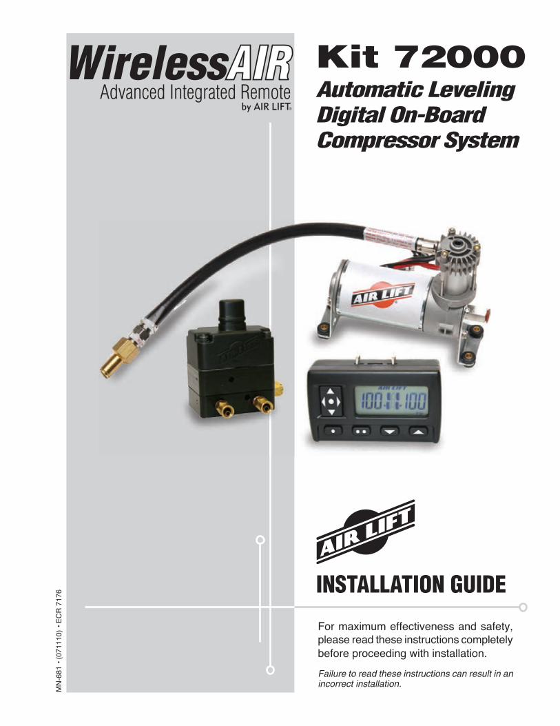
For maximum effectiveness and safety, please read these instructions completely before proceeding with installation.
Failure to read these instructions can result in an incorrect installation.
MN
-681
• (
0711
10)
• E
CR
717
6 INSTALLATION GUIDE
Kit 72000Automatic Leveling Digital On-Board Compressor System

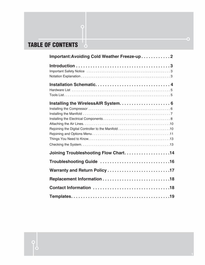
Important:Avoiding Cold Weather Freeze-up . . . . . . . . . . . . 2
Introduction . . . . . . . . . . . . . . . . . . . . . . . . . . . . . . . . . . . . . . . 3Important Safety Notice . . . . . . . . . . . . . . . . . . . . . . . . . . . . . . . . . . . . . . . . . . . . . 3Notation Explanation . . . . . . . . . . . . . . . . . . . . . . . . . . . . . . . . . . . . . . . . . . . . . . . . 3
Installation Schematic. . . . . . . . . . . . . . . . . . . . . . . . . . . . . . . 4Hardware List . . . . . . . . . . . . . . . . . . . . . . . . . . . . . . . . . . . . . . . . . . . . . . . . . . . . . 5Tools List . . . . . . . . . . . . . . . . . . . . . . . . . . . . . . . . . . . . . . . . . . . . . . . . . . . . . . . . . 5
Installing the WirelessAIR System. . . . . . . . . . . . . . . . . . . . . 6Installing the Compressor . . . . . . . . . . . . . . . . . . . . . . . . . . . . . . . . . . . . . . . . . . . . 6Installing the Manifold . . . . . . . . . . . . . . . . . . . . . . . . . . . . . . . . . . . . . . . . . . . . . . . 7Installing the Electrical Components . . . . . . . . . . . . . . . . . . . . . . . . . . . . . . . . . . . . 8Attaching the Air Lines. . . . . . . . . . . . . . . . . . . . . . . . . . . . . . . . . . . . . . . . . . . . . . .10Rejoining the Digital Controller to the Manifold . . . . . . . . . . . . . . . . . . . . . . . . . . . .10Rejoining and Options Menu . . . . . . . . . . . . . . . . . . . . . . . . . . . . . . . . . . . . . . . . . .11Things You Need to Know . . . . . . . . . . . . . . . . . . . . . . . . . . . . . . . . . . . . . . . . . . . .13
Checking the System. . . . . . . . . . . . . . . . . . . . . . . . . . . . . . . . . . . . . . . . . . . . . . . .13
Joining Troubleshooting Flow Chart . . . . . . . . . . . . . . . . . . .14
Troubleshooting Guide . . . . . . . . . . . . . . . . . . . . . . . . . . . . .16
Warranty and Return Policy . . . . . . . . . . . . . . . . . . . . . . . . . .17
Replacement Information . . . . . . . . . . . . . . . . . . . . . . . . . . . .18
Contact Information . . . . . . . . . . . . . . . . . . . . . . . . . . . . . . . .18
Templates . . . . . . . . . . . . . . . . . . . . . . . . . . . . . . . . . . . . . . . . .19
TABLE OF CONTENTS
1
2 MN-681
WirelessAIR
IMPORTANT: To Avoid Cold Weather Freeze-up
Important
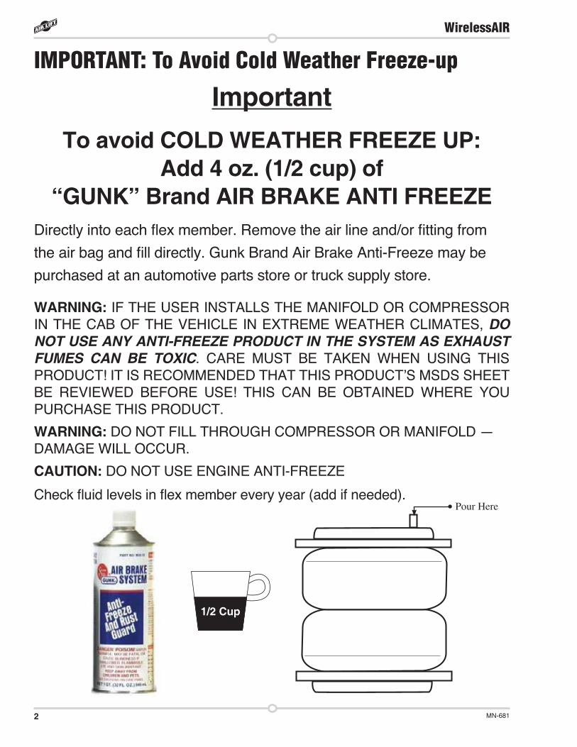
To avoid COLD WEATHER FREEZE UP:Add 4 oz. (1/2 cup) of
“GUNK” Brand AIR BRAKE ANTI FREEZEDirectly into each flex member. Remove the air line and/or fitting from the air bag and fill directly. Gunk Brand Air Brake Anti-Freeze may be purchased at an automotive parts store or truck supply store.
WARNING: IF THE USER INSTALLS THE MANIFOLD OR COMPRESSOR IN THE CAB OF THE VEHICLE IN EXTREME WEATHER CLIMATES, DO NOT USE ANY ANTI-FREEZE PRODUCT IN THE SYSTEM AS EXHAUST FUMES CAN BE TOXIC. CARE MUST BE TAKEN WHEN USING THIS PRODUCT! IT IS RECOMMENDED THAT THIS PRODUCT’S MSDS SHEET BE REVIEWED BEFORE USE! THIS CAN BE OBTAINED WHERE YOU PURCHASE THIS PRODUCT.
WARNING: DO NOT FILL THROUGH COMPRESSOR OR MANIFOLD — DAMAGE WILL OCCUR.
CAUTION: DO NOT USE ENGINE ANTI-FREEZE
Check fluid levels in flex member every year (add if needed).
1/2 Cup
Pour Here
3MN-681
WirelessAIR
IntroductionThe purpose of this publication is to assist with the installation, maintenance and troubleshooting of the WirelessAIR System.
It is important to read and understand the entire installation guide before beginning installation or performing any maintenance, service or repair. The information here includes a hardware list, step-by-step installation information, safety information and a troubleshooting guide.
Air Lift Company reserves the right to make changes and improvements to its products and publications at any time. Contact Air Lift Company at (800) 248-0892 for the latest version of this manual or find it online at http://www.airliftcompany.com/wirelessair.htm.
SYSTEM INFORMATION The WirelessAIR (Advanced Integrated Remote) is designed for automatic digital leveling of the on-board compressor system. The kit includes a compressor, manifold, wiring harness, and wireless digital controller. With the capability to control two air springs independently, the system can be used in or outside the vehicle, for adjustments in full view of the vehicle.
The wireless digital controller is a compact, battery powered unit that features advanced integrated diagnostic capabilities for increased safety and peace of mind. It also includes a clip that can be attached to the vehicle’s visor. Two user-defined memory buttons are provided for frequently used settings. As an added safety measure, minimum air pressures are automatically maintained. The manifold is also weather resistant and waterproof up to 2 ft for maximum life expectancy.
IMPORTANT SAFETY NOTICEThe installation of this kit does not alter the Gross Vehicle Weight Rating (GVWR) or payload of the vehicle. Check your vehicle’s owner’s manual and do not exceed the maximum load listed for your vehicle.
Gross Vehicle Weight Rating: The maximum allowable weight of the fully loaded vehicle (including passengers and cargo). This number — along with other weight limits, as well as tire, rim size and inflation pressure data — is shown on the vehicle’s Safety Compliance Certification Label.
Payload: The combined, maximum allowable weight of cargo and passengers that the truck is designed to carry. Payload is GVWR minus the Base Curb Weight.
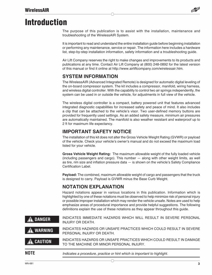
NOTATION EXPLANATIONHazard notations appear in various locations in this publication. Information which is highlighted by one of these notations must be observed to help minimize risk of personal injury or possible improper installation which may render the vehicle unsafe. Notes are used to help emphasize areas of procedural importance and provide helpful suggestions. The following definitions explain the use of these notations as they appear throughout this guide.
INDICATES IMMEDIATE HAZARDS WHICH WILL RESULT IN SEVERE PERSONAL INJURY OR DEATH.
INDICATES HAZARDS OR UNSAFE PRACTICES WHICH COULD RESULT IN SEVERE PERSONAL INJURY OR DEATH.
INDICATES HAZARDS OR UNSAFE PRACTICES WHICH COULD RESULT IN DAMAGE TO THE MACHINE OR MINOR PERSONAL INJURY.
Indicates a procedure, practice or hint which is important to highlight.
DANGER
NOTE
WARNING
CAUTION
4 MN-681
WirelessAIR
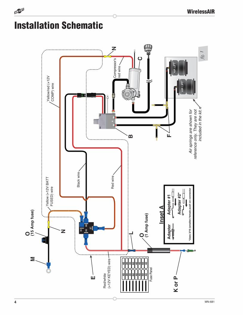
Installation Schematic
8787
85858686
3030
40 30 30 60 40 40 50 40
40 30 30 60 40 40 50 40
Fuse
Pan
el
F
C
N
B
E
M
N
O (1 A
mp
fuse
)
K o
r P
LO (15
Am
p fu
se)
Inse
t AA
dapt
erA
dapt
er #
1
Ada
pter
#2*
*Use
s 3/
16 (s
mal
ler)
fem
ale
push
on
conn
ecto
rA
ir sp
rings
are
sho
wn
for
refe
renc
e on
ly. T
hey
are
not
incl
uded
in th
e ki
t.fig
. 1
Red
/whi
te
(+12
V K
EY
ED
) w
ire
Yel
low
(+1
2V B
AT
T
FU
SE
D)
wire
Yel
low
/red
(+1
2V
CO
MP
) w
ire
Red
wire
Bla
ck w
ire
Com
pres
sor’s
re
d w
ire
5MN-681
WirelessAIR
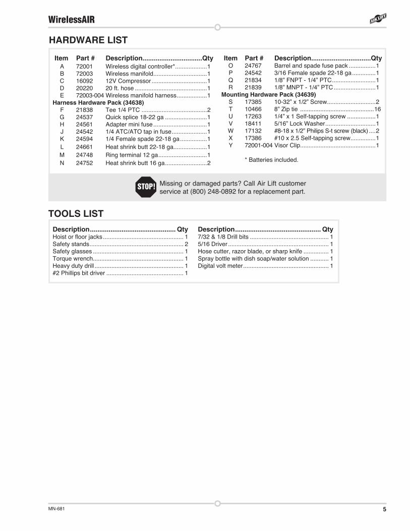
TOOLS LISTDescription .............................................. QtyHoist or floor jacks ................................................ 1Safety stands ........................................................ 2Safety glasses ...................................................... 1Torque wrench...................................................... 1Heavy duty drill ..................................................... 1#2 Phillips bit driver .............................................. 1
Description .............................................. Qty 7/32 & 1/8 Drill bits ............................................... 15/16 Driver ............................................................ 1Hose cutter, razor blade, or sharp knife ............... 1Spray bottle with dish soap/water solution ........... 1Digital volt meter ................................................... 1
HARDWARE LIST
Item Part # Description................................Qty A 72001 Wireless digital controller* ...................1 B 72003 Wireless manifold ................................1 C 16092 12V Compressor .................................1 D 20220 20 ft. hose ...........................................1 E 72003-004 Wireless manifold harness ..................1 Harness Hardware Pack (34638) F 21838 Tee 1/4 PTC .......................................2 G 24537 Quick splice 18-22 ga .........................1 H 24561 Adapter mini fuse ................................1 J 24542 1/4 ATC/ATO tap in fuse .....................1 K 24594 1/4 Female spade 22-18 ga ................1 L 24661 Heat shrink butt 22-18 ga....................1 M 24748 Ring terminal 12 ga .............................1 N 24752 Heat shrink butt 16 ga .........................2
Item Part # Description................................Qty O 24767 Barrel and spade fuse pack ................1P 24542 3/16 Female spade 22-18 ga ..............1Q 21834 1/8” FNPT - 1/4” PTC ..........................1R 21839 1/8” MNPT - 1/4” PTC .........................1
Mounting Hardware Pack (34639)S 17385 10-32” x 1/2” Screw .............................2T 10466 8” Zip tie ............................................16 U 17263 1/4” x 1 Self-tapping screw .................1V 18411 5/16” Lock Washer ..............................1 W 17132 #8-18 x 1/2” Philips S-t screw (black) ....2X 17386 #10 x 2.5 Self-tapping screw...............1Y 72001-004 Visor Clip .............................................1
* Batteries included.
Missing or damaged parts? Call Air Lift customer service at (800) 248-0892 for a replacement part.
STOP!
6 MN-681
WirelessAIR
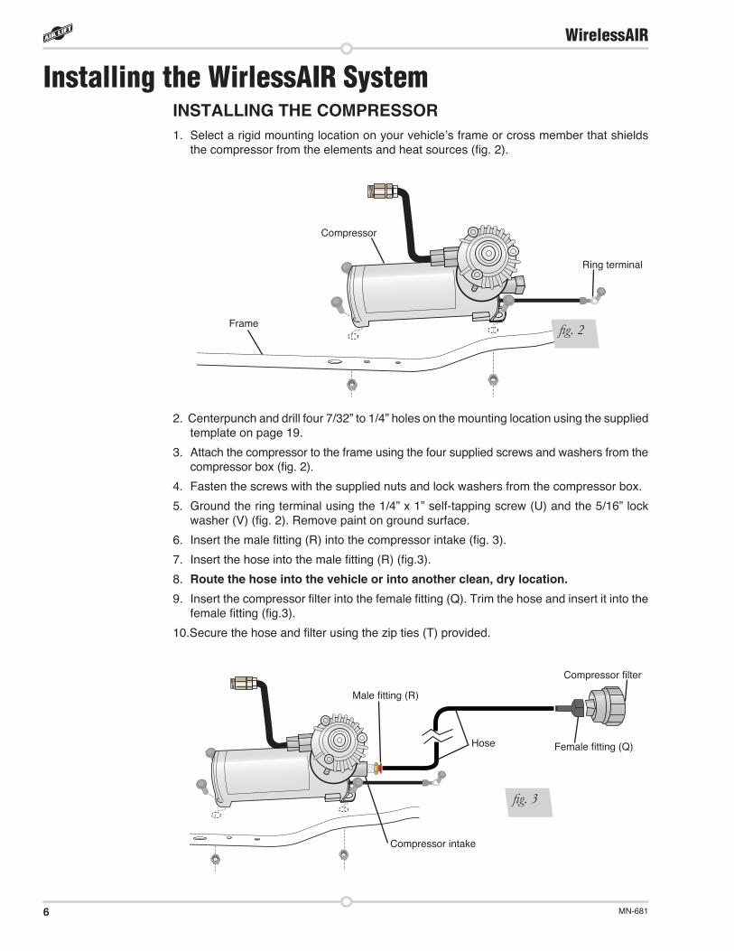
Installing the WirlessAIR SystemINSTALLING THE COMPRESSOR1. Select a rigid mounting location on your vehicle’s frame or cross member that shields
the compressor from the elements and heat sources (fig. 2).
2. Centerpunch and drill four 7/32” to 1/4” holes on the mounting location using the supplied template on page 19.
3. Attach the compressor to the frame using the four supplied screws and washers from the compressor box (fig. 2).
4. Fasten the screws with the supplied nuts and lock washers from the compressor box.
5. Ground the ring terminal using the 1/4” x 1” self-tapping screw (U) and the 5/16” lock washer (V) (fig. 2). Remove paint on ground surface.
6. Insert the male fitting (R) into the compressor intake (fig. 3).
7. Insert the hose into the male fitting (R) (fig.3).
8. Route the hose into the vehicle or into another clean, dry location. 9. Insert the compressor filter into the female fitting (Q). Trim the hose and insert it into the
female fitting (fig.3).
10.Secure the hose and filter using the zip ties (T) provided.
Compressor
Frame
Ring terminal
fig. 2
Male fitting (R)
Compressor intake
Hose Female fitting (Q)
Compressor filter
fig. 3
7MN-681
WirelessAIR
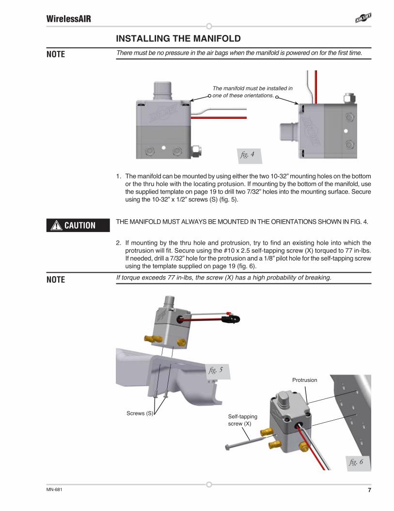
INSTALLING THE MANIFOLDThere must be no pressure in the air bags when the manifold is powered on for the first time.
1. The manifold can be mounted by using either the two 10-32” mounting holes on the bottom or the thru hole with the locating protusion. If mounting by the bottom of the manifold, use the supplied template on page 19 to drill two 7/32” holes into the mounting surface. Secure using the 10-32” x 1/2” screws (S) (fig. 5).
THE MANIFOLD MUST ALWAYS BE MOUNTED IN THE ORIENTATIONS SHOWN IN FIG. 4.
2. If mounting by the thru hole and protrusion, try to find an existing hole into which the protrusion will fit. Secure using the #10 x 2.5 self-tapping screw (X) torqued to 77 in-lbs.If needed, drill a 7/32” hole for the protrusion and a 1/8” pilot hole for the self-tapping screw using the template supplied on page 19 (fig. 6).
If torque exceeds 77 in-lbs, the screw (X) has a high probability of breaking.
CAUTION
NOTE
NOTE
The manifold must be installed in one of these orientations.
fig. 4
Self-tapping screw (X)
Protrusion
Screws (S)
fig. 6
fig. 5
8 MN-681
WirelessAIR
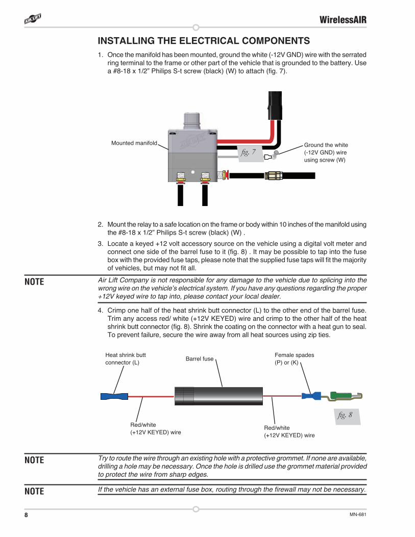
INSTALLING THE ELECTRICAL COMPONENTS1. Once the manifold has been mounted, ground the white (-12V GND) wire with the serrated
ring terminal to the frame or other part of the vehicle that is grounded to the battery. Use a #8-18 x 1/2” Philips S-t screw (black) (W) to attach (fig. 7).
2. Mount the relay to a safe location on the frame or body within 10 inches of the manifold using the #8-18 x 1/2” Philips S-t screw (black) (W) .
3. Locate a keyed +12 volt accessory source on the vehicle using a digital volt meter and connect one side of the barrel fuse to it (fig. 8) . It may be possible to tap into the fuse box with the provided fuse taps, please note that the supplied fuse taps will fit the majority of vehicles, but may not fit all.
Air Lift Company is not responsible for any damage to the vehicle due to splicing into the wrong wire on the vehicle’s electrical system. If you have any questions regarding the proper +12V keyed wire to tap into, please contact your local dealer.
4. Crimp one half of the heat shrink butt connector (L) to the other end of the barrel fuse. Trim any access red/ white (+12V KEYED) wire and crimp to the other half of the heat shrink butt connector (fig. 8). Shrink the coating on the connector with a heat gun to seal. To prevent failure, secure the wire away from all heat sources using zip ties.
Try to route the wire through an existing hole with a protective grommet. If none are available, drilling a hole may be necessary. Once the hole is drilled use the grommet material provided to protect the wire from sharp edges.
If the vehicle has an external fuse box, routing through the firewall may not be necessary.
NOTE
NOTE
Barrel fuseHeat shrink butt connector (L)
Female spades (P) or (K)
fig. 8Red/white (+12V KEYED) wire
Red/white (+12V KEYED) wire
NOTE
Ground the white (-12V GND) wire using screw (W)
Mounted manifold
fig. 7
9MN-681
WirelessAIR
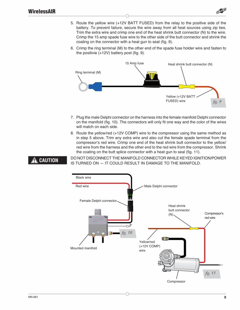
7. Plug the male Delphi connector on the harness into the female manifold Delphi connector on the manifold (fig. 10). The connectors will only fit one way and the color of the wires will match on each side.
8. Route the yellow/red (+12V COMP) wire to the compressor using the same method as in step 5 above. Trim any extra wire and also cut the female spade terminal from the compressor’s red wire. Crimp one end of the heat shrink butt connector to the yellow/red wire from the harness and the other end to the red wire from the compressor. Shrink the coating on the butt splice connector with a heat gun to seal (fig. 11).
DO NOT DISCONNECT THE MANIFOLD CONNECTOR WHILE KEYED IGNITION/POWER IS TURNED ON — IT COULD RESULT IN DAMAGE TO THE MANIFOLD.
CAUTION
Ring terminal (M)
15 Amp fuse Heat shrink butt connector (N)
fig. 9Yellow (+12V BATT FUSED) wire
5. Route the yellow wire (+12V BATT FUSED) from the relay to the positive side of the battery. To prevent failure, secure the wire away from all heat sources using zip ties. Trim the extra wire and crimp one end of the heat shrink butt connector (N) to the wire. Crimp the 15 amp spade fuse wire to the other side of the butt connector and shrink the coating on the connector with a heat gun to seal (fig. 9).
6. Crimp the ring terminal (M) to the other end of the spade fuse holder wire and fasten to the positivie (+12V) battery post (fig. 9).
Mounted manifold
Female Delphi connector
Male Delphi connector
Heat shrink butt connector (N)
Compressor
fig. 11
fig. 10
Red wire
Black wire
Yellow/red (+12V COMP) wire
Compressor’s red wire
10 MN-681
WirelessAIR
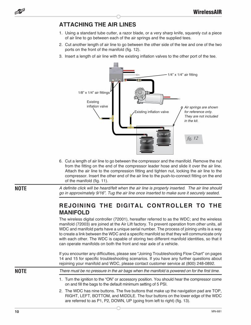
ATTACHING THE AIR LINES1. Using a standard tube cutter, a razor blade, or a very sharp knife, squarely cut a piece
of air line to go between each of the air springs and the supplied tees.
2. Cut another length of air line to go between the other side of the tee and one of the two ports on the front of the manifold (fig. 12).
3. Insert a length of air line with the existing inflation valves to the other port of the tee.
6. Cut a length of air line to go between the compressor and the manifold. Remove the nut from the fitting on the end of the compressor leader hose and slide it over the air line. Attach the air line to the compression fitting and tighten nut, locking the air line to the compressor. Insert the other end of the air line to the push-to-connect fitting on the end of the manifold (fig. 11).
A definite click will be heard/felt when the air line is properly inserted. The air line should go in approximately 9/16”. Tug the air line once inserted to make sure it securely seated.
NOTE
REJOINING THE DIGITAL CONTROLLER TO THE MANIFOLDThe wireless digital controller (72001), hereafter referred to as the WDC; and the wireless manifold (72003) are joined at the Air Lift factory. To prevent operation from other units, all WDC and manifold parts have a unique serial number. The process of joining units is a way to create a link between the WDC and a specific manifold so that they will communicate only with each other. The WDC is capable of storing two different manifold identities, so that it can operate manifolds on both the front and rear axle of a vehicle.
If you encounter any difficulties, please see “Joining Troubleshooting Flow Chart” on pages 14 and 15 for specific troubleshooting scenarios. If you have any further questions about rejoining your manifold and WDC, please contact customer service at (800) 248-0892.
There must be no pressure in the air bags when the manifold is powered on for the first time.
1. Turn the ignition to the “ON” or accessory position. You should hear the compressor come on and fill the bags to the default minimum setting of 5 PSI.
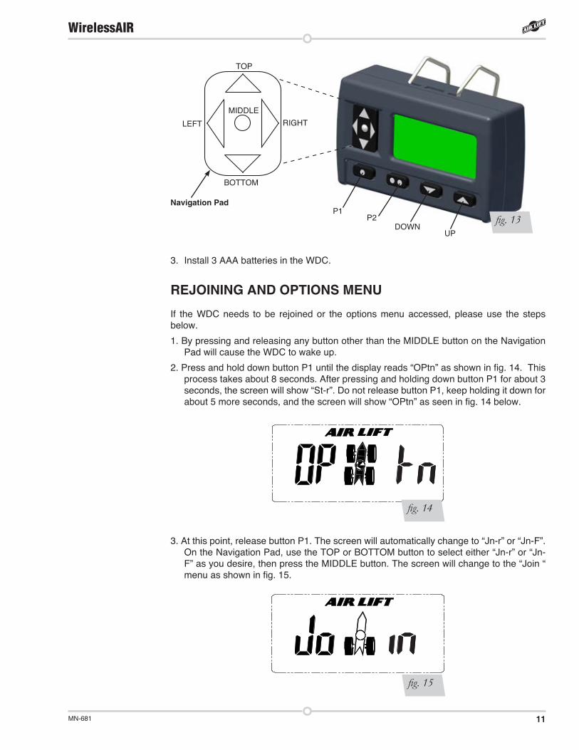
2. The WDC has nine buttons. The five buttons that make up the navigation pad are TOP, RIGHT, LEFT, BOTTOM, and MIDDLE. The four buttons on the lower edge of the WDC are referred to as P1, P2, DOWN, UP (going from left to right) (fig. 13).
NOTE
Air springs are shown for reference only. They are not included in the kit.
Existing inflation valve
Existing inflation valve
1/8” x 1/4” air fittings
1/4” x 1/4” air fitting
fig. 12
11MN-681
WirelessAIR
TOP
RIGHT
BOTTOM
LEFT
MIDDLE
P1P2
DOWNUP
fig. 13Navigation Pad
3. Install 3 AAA batteries in the WDC.
REJOINING AND OPTIONS MENU
If the WDC needs to be rejoined or the options menu accessed, please use the steps below.
1. By pressing and releasing any button other than the MIDDLE button on the Navigation Pad will cause the WDC to wake up.
2. Press and hold down button P1 until the display reads “OPtn” as shown in fig. 14. This process takes about 8 seconds. After pressing and holding down button P1 for about 3 seconds, the screen will show “St-r”. Do not release button P1, keep holding it down for about 5 more seconds, and the screen will show “OPtn” as seen in fig. 14 below.
3. At this point, release button P1. The screen will automatically change to “Jn-r” or “Jn-F”. On the Navigation Pad, use the TOP or BOTTOM button to select either “Jn-r” or “Jn-F” as you desire, then press the MIDDLE button. The screen will change to the “Join “ menu as shown in fig. 15.
fig. 15
fig. 14
12 MN-681
WirelessAIR
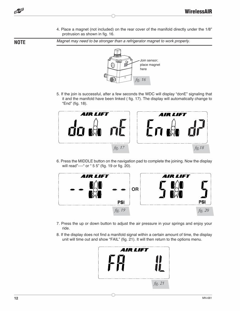
4. Place a magnet (not included) on the rear cover of the manifold directly under the 1/8” protrusion as shown in fig. 16.
Magnet may need to be stronger than a refrigerator magnet to work properly.
5. If the join is successful, after a few seconds the WDC will display “donE” signaling that it and the manifold have been linked ( fig. 17). The display will automatically change to “End” (fig. 18).
6. Press the MIDDLE button on the navigation pad to complete the joining. Now the display will read”----“ or “ 5 5” (fig. 19 or fig. 20).
7. Press the up or down button to adjust the air pressure in your springs and enjoy your ride.
8. If the display does not find a manifold signal within a certain amount of time, the display unit will time out and show “FAIL” (fig. 21). It will then return to the options menu.
fig. 16
Join sensor; place magnet here
fig. 17 fig.18
fig. 21
fig. 19 fig. 20
OR
NOTE
13MN-681
WirelessAIR
9. If the manifold joined to was previously joined to the other axle, that link is automatically removed when it is joined to a new axle. If no buttons are pressed when in the options menu, the display will return to the operation screen.
10. To view the Options menu hold down P1 and continue to hold from when “STORE” appears until when “OPTN” appears.
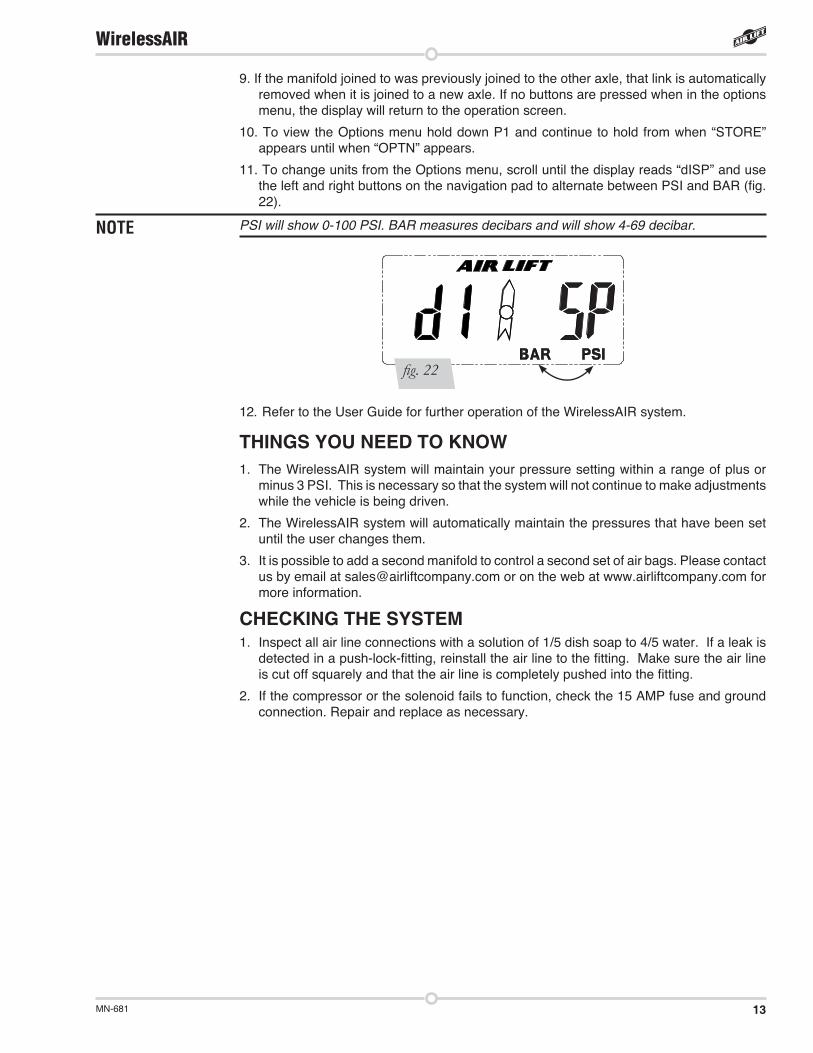
11. To change units from the Options menu, scroll until the display reads “dISP” and use the left and right buttons on the navigation pad to alternate between PSI and BAR (fig. 22).
PSI will show 0-100 PSI. BAR measures decibars and will show 4-69 decibar.
12. Refer to the User Guide for further operation of the WirelessAIR system.
THINGS YOU NEED TO KNOW1. The WirelessAIR system will maintain your pressure setting within a range of plus or
minus 3 PSI. This is necessary so that the system will not continue to make adjustments while the vehicle is being driven.
2. The WirelessAIR system will automatically maintain the pressures that have been set until the user changes them.
3. It is possible to add a second manifold to control a second set of air bags. Please contact us by email at [email protected] or on the web at www.airliftcompany.com for more information.
CHECKING THE SYSTEM1. Inspect all air line connections with a solution of 1/5 dish soap to 4/5 water. If a leak is
detected in a push-lock-fitting, reinstall the air line to the fitting. Make sure the air line is cut off squarely and that the air line is completely pushed into the fitting.
2. If the compressor or the solenoid fails to function, check the 15 AMP fuse and ground connection. Repair and replace as necessary.
fig. 22
NOTE
14 MN-681
WirelessAIR
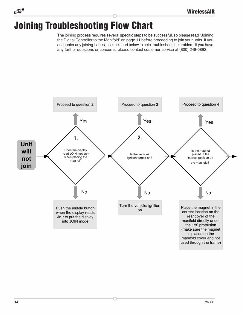
Joining Troubleshooting Flow ChartThe joining process requires several specific steps to be successful, so please read “Joining the Digital Controller to the Manifold” on page 11 before proceeding to join your units. If you encounter any joining issues, use the chart below to help troubleshoot the problem. If you have any further questions or concerns, please contact customer service at (800) 248-0892.
Unit will not join
Is the vehicle/ ignition turned on?
Is the magnet placed in the
correct position on
the manifold?
Yes
No No
Turn the vehicle/ ignition on
Does the display read JOIN, not Jn-r when placing the
magnet?
Yes
No
Push the middle button when the display reads Jn-r to put the display
into JOIN mode
Proceed to question 2
1. 2.
Proceed to question 3 Proceed to question 4
Place the magnet in the correct location on the
rear cover of the manifold directly under
the 1/8” protrusion (make sure the magnet
is placed on the manifold cover and not
used through the frame)
Yes
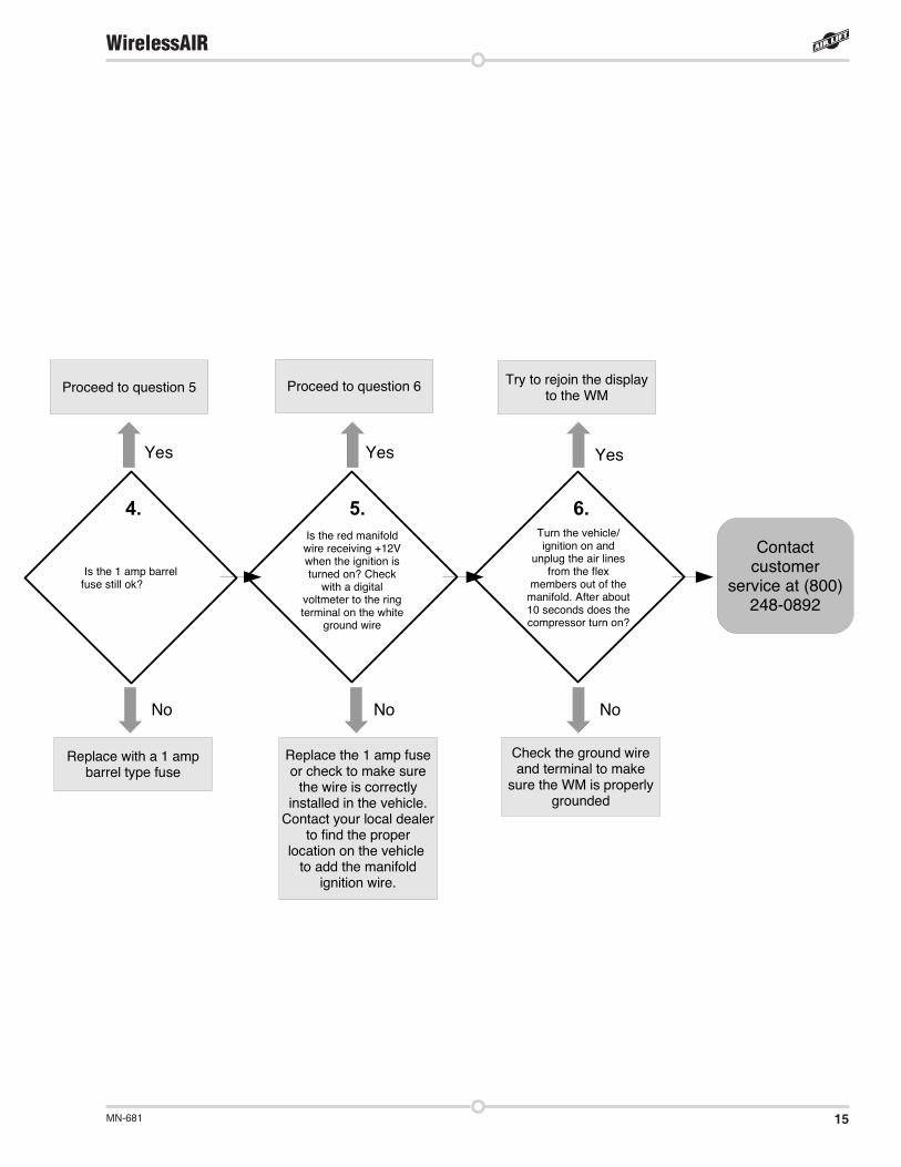
15MN-681
WirelessAIR
Is the 1 amp barrel fuse still ok?
Is the red manifold wire receiving +12V when the ignition is turned on? Check
with a digital voltmeter to the ring terminal on the white
ground wire
Turn the vehicle/ ignition on and
unplug the air lines from the flex
members out of the manifold. After about 10 seconds does the compressor turn on?
Contact customer
service at (800) 248-0892
Yes Yes Yes
No No No
4. 5. 6.
Replace with a 1 amp barrel type fuse
Proceed to question 5
Replace the 1 amp fuse or check to make sure
the wire is correctly installed in the vehicle.
Contact your local dealer to find the proper
location on the vehicle to add the manifold
ignition wire.
Proceed to question 6 Try to rejoin the display to the WM
Check the ground wire and terminal to make
sure the WM is properly grounded
16 MN-681
WirelessAIR
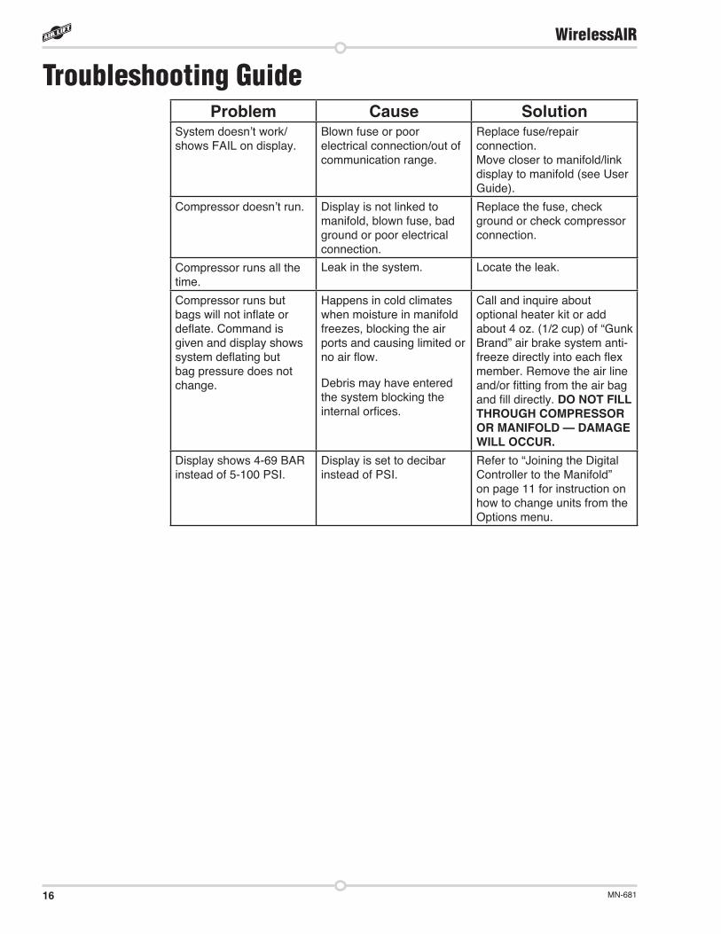
Problem Cause SolutionSystem doesn’t work/shows FAIL on display.
Blown fuse or poor electrical connection/out of communication range.
Replace fuse/repair connection.Move closer to manifold/link display to manifold (see User Guide).
Compressor doesn’t run. Display is not linked to manifold, blown fuse, bad ground or poor electrical connection.
Replace the fuse, check ground or check compressor connection.
Compressor runs all the time.
Leak in the system. Locate the leak.
Compressor runs but bags will not inflate or deflate. Command is given and display shows system deflating but bag pressure does not change.
Happens in cold climates when moisture in manifold freezes, blocking the air ports and causing limited or no air flow.
Debris may have entered the system blocking the internal orfices.
Call and inquire about optional heater kit or add about 4 oz. (1/2 cup) of “Gunk Brand” air brake system anti-freeze directly into each flex member. Remove the air line and/or fitting from the air bag and fill directly. DO NOT FILL THROUGH COMPRESSOR OR MANIFOLD — DAMAGE WILL OCCUR.
Display shows 4-69 BAR instead of 5-100 PSI.
Display is set to decibar instead of PSI.
Refer to “Joining the Digital Controller to the Manifold” on page 11 for instruction on how to change units from the Options menu.
Troubleshooting Guide
17MN-681
WirelessAIR
Air Lift 1000 .................... Lifetime LimitedRideControl .................... Lifetime LimitedSlamAir ........................... Lifetime LimitedLoadLifter 5000*............. Lifetime LimitedLifeStyle** .......................... 1 Year Limited
Load Controller (I) ............ 2 Year LimitedLoad Controller (II) ........... 2 Year LimitedSmartAir ............................ 2 Year LimitedWireless AIR...................... 2 Year LimitedOther Accessories ............ 2 Year Limited
*formerly SuperDuty**formerly EasyStreet
Air Lift Company warrants its products, for the time periods listed below, to the original retail purchaser against manufacturing defects when used on catalog-listed applications on cars, vans, light trucks and motorhomes under normal operating conditions for as long as Air Lift manufactures the product. The warranty does not apply to products that have been improperly applied, improperly installed, used in racing or off-road applications, used for commercial purposes, or which have not been maintained in accordance with installation instructions furnished with all products. The consumer will be responsible for removing (labor charges) the defective product from the vehicle and returning it, transportation costs prepaid, to the dealer from which it was purchased or to Air Lift Company for verification. Removal of the manifold cover voids Air Lift warranty.
Air Lift will repair or replace, at its option, defective products or components. A minimum $10.00 shipping and handling charge will apply to all warranty claims. Before returning any defective product, you must call Air Lift at (800) 248-0892 in the U.S. and Canada (elsewhere, (517) 322-2144) for a Returned Materials Authorization (RMA) number. Returns to Air Lift can be sent to: Air Lift Company • 2727 Snow Road • Lansing, MI • 48917.
Product failures resulting from abnormal use or misuse are excluded from this warranty. The loss of use of the product, loss of time, inconvenience, commercial loss or consequential damages is not covered. The consumer is responsible for installation/reinstallation (labor charges) of the product. Air Lift Company reserves the right to change the design of any product without assuming any obligation to modify any product previously manufactured.
This warranty gives you specific legal rights and you may also have other rights that vary from state-to-state. Some states do not allow limitations on how long an implied warranty lasts or allow the exclusion or limitation of incidental or consequential damages. The above limitation or exclusion may not apply to you. There are no warranties, expressed or implied including any implied warranties of merchantability and fitness, which extend beyond this warranty period. There are no warranties that extend beyond the description on the face hereof. Seller disclaims the implied warranty of merchantability. (Dated proof of purchase required.)
Warranty and Returns Policy
18 MN-681
WirelessAIR
Replacement InformationIf you need replacement parts, contact the local dealer or call Air Lift customer service at(800) 248-0892. Most parts are immediately available and can be shipped the same day.
Contact Air Lift Company customer service at (800) 248-0892 first if:• Parts are missing from the kit.• Need technical assistance on installation or operation.• Broken or defective parts in the kit.• Wrong parts in the kit.• Have a warranty claim or question.
Contact the retailer where the kit was purchased:• If it is necessary to return or exchange the kit for any reason.• If there is a problem with shipping if shipped from the retailer.• If there is a problem with the price.
Contact InformationIf you have any questions, comments or need technical assistance, contact our customer service department by calling (800) 248-0892, Monday through Friday, 8 a.m. to 7 p.m. Eastern Time. For calls from outside the USA or Canada, our local number is (517) 322-2144.
For inquiries by mail, our address is PO Box 80167, Lansing, MI 48908-0167. Our shipping address for returns is 2727 Snow Road, Lansing, MI 48917.
You may also contact us anytime by e-mail at [email protected] or on the web at www.airliftcompany.com.
19MN-681
WirelessAIR
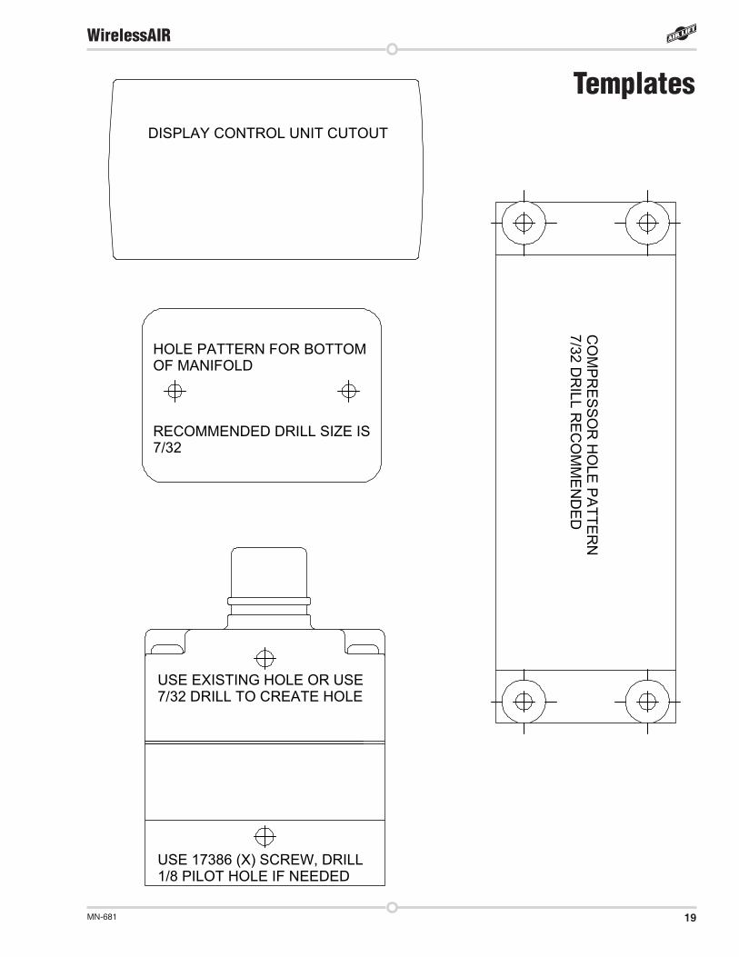
TemplatesDISPLAY CONTROL UNIT CUTOUT
HOLE PATTERN FOR BOTTOM OF MANIFOLD
RECOMMENDED DRILL SIZE IS7/32
USE EXISTING HOLE OR USE 7/32 DRILL TO CREATE HOLE
USE 17386 (X) SCREW, DRILL 1/8 PILOT HOLE IF NEEDED
********DRAWINGS HAS TO BE SCALED 1:1 IN MANUAL*********
CO
MP
RE
SS
OR
HO
LE P
AT
TE
RN
7/32 D
RILL R
EC
OM
ME
ND
ED


Air Lift Company • 2727 Snow Road • Lansing, MI 48917 or PO Box 80167 • Lansing, MI 48908-0167 Toll Free (800) 248-0892 • Local (517) 322-2144 • Fax (517) 322-0240 • www.airliftcompany.com
Thank you for purchasing Air Lift products — the professional installer’s choice!
Printed in the USA
Need Help?Contact our customer service department by calling (800) 248-0892, Monday through Friday, 8 a.m. to 7 p.m. Eastern Time. For calls from outside the USA or Canada, our local number is (517) 322-2144.
Register your warranty online at www.airliftcompany.com/warranty