Embed Size (px)
Citation preview
-1-
KGD-802KGD-802-P
Industrial 8-Port Gigabit Ethernet Switcheswith 2 SFP Slots and 4 PoE PSE Ports
User,s Manual
DOC.111205

-2-
(C) 2007 KTI Networks Inc. All rights reserved. No part of this documentation may be reproducedin any form or by any means or used to make any directive work (such as transla-tion or transformation) without permission from KTI Networks Inc.
KTI Networks Inc. reserves the right to revise this documentation and to make changes in contentfrom time to time without obligation on the part of KTI Networks Inc. to provide notification of suchrevision or change.
For more information, contact:
United States KTI Networks Inc.P.O. BOX 631008Houston, Texas 77263-1008
Phone: 713-2663891Fax: 713-2663893E-mail: [email protected]: http://www.ktinet.com/
International Fax: 886-2-26983873E-mail: [email protected]: http://www.ktinet.com.tw/
-3-
The information contained in this document is subject to change without prior notice. Copyright (C). AllRights Reserved.
TRADEMARKSEthernet is a registered trademark of Xerox Corp.
WARNING:This equipment has been tested and found to comply with the limits for a Class A digital device, pursuantto Part 15 of the FCC Rules. These limits are designed to provide reasonable protection against harmfulinterference when the equipment is operated in a commercial environment. This equipment generates,uses, and can radiate radio frequency energy and if not installed and used in accordance with theinstruction manual may cause harmful interference in which case the user will be required to correct theinterference at his own expense.NOTICE:(1) The changes or modifications not expressively approved by the party responsible for compliancecould void the user's authority to operate the equipment.(2) Shielded interface cables and AC power cord, if any, must be used in order to comply with theemission limits.
CISPR A COMPLIANCE:This device complies with EMC directive of the European Community and meets or exceeds the followingtechnical standard.EN 55022 - Limits and Methods of Measurement of Radio Interference Characteristics of InformationTechnology Equipment. This device complies with CISPR Class A.WARNING: This is a Class A product. In a domestic environment this product may cause radio interfer-ence in which case the user may be required to take adequate measures.
CE NOTICE
Marking by the symbol indicates compliance of this equipment to the EMC directive of the Euro-pean Community. Such marking is indicative that this equipment meets or exceeds the following techni-cal standards:
EMC Class AEN61000-6-4/2001 IEC 61000-6-4/1997EN55011/1998+A1/1999+A2/2002
CISPR11:1997+A1/1999+A2/2002IEC 61000-3-2/2000IEC 61000-3-3:1994/A1:2001
EN61000-6-2/2005 IEC 61000-6-2/2005IEC 61000-4-2:2001IEC 61000-4-3:2002/A1:2002IEC 61000-4-4:2004IEC 61000-4-5:2001IEC 61000-4-6:1996+A1/2000IEC 61000-4-8:2001IEC 61000-4-11:2004
-4-
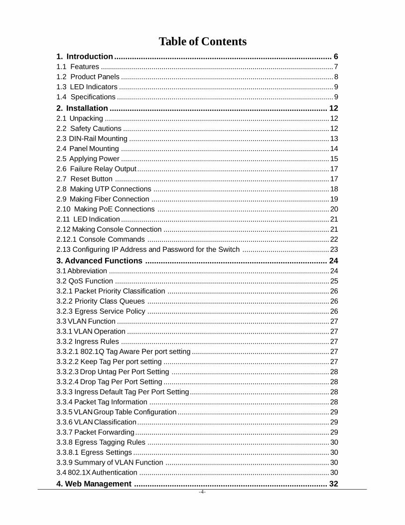
Table of Contents1. Introduction .................................................................................................. 61.1 Features ...................................................................................................................71.2 Product Panels .........................................................................................................81.3 LED Indicators ..........................................................................................................91.4 Specifications ...........................................................................................................92. Installation .................................................................................................. 122.1 Unpacking ............................................................................................................... 122.2 Safety Cautions ...................................................................................................... 122.3 DIN-Rail Mounting ................................................................................................... 132.4 Panel Mounting ....................................................................................................... 142.5 Applying Power ....................................................................................................... 152.6 Failure Relay Output ............................................................................................... 172.7 Reset Button .......................................................................................................... 172.8 Making UTP Connections ....................................................................................... 182.9 Making Fiber Connection ........................................................................................ 192.10 Making PoE Connections ..................................................................................... 202.11 LED Indication ....................................................................................................... 212.12 Making Console Connection .................................................................................. 212.12.1 Console Commands .......................................................................................... 222.13 Configuring IP Address and Password for the Switch ........................................... 233. Advanced Functions .................................................................................. 243.1 Abbreviation ............................................................................................................. 243.2 QoS Function .......................................................................................................... 253.2.1 Packet Priority Classification ................................................................................ 263.2.2 Priority Class Queues .......................................................................................... 263.2.3 Egress Service Policy .......................................................................................... 263.3 VLAN Function ......................................................................................................... 273.3.1 VLAN Operation .................................................................................................... 273.3.2 Ingress Rules ....................................................................................................... 273.3.2.1 802.1Q Tag Aware Per port setting .................................................................... 273.3.2.2 Keep Tag Per port setting .................................................................................. 273.3.2.3 Drop Untag Per Port Setting .............................................................................. 283.3.2.4 Drop Tag Per Port Setting .................................................................................. 283.3.3 Ingress Default Tag Per Port Setting..................................................................... 283.3.4 Packet Tag Information ......................................................................................... 283.3.5 VLAN Group Table Configuration ........................................................................... 293.3.6 VLAN Classification............................................................................................... 293.3.7 Packet Forwarding................................................................................................ 293.3.8 Egress Tagging Rules .......................................................................................... 303.3.8.1 Egress Settings ................................................................................................. 303.3.9 Summary of VLAN Function ................................................................................. 303.4 802.1X Authentication .............................................................................................. 304. Web Management ....................................................................................... 32
-5-
4.1 Start Browser Software and Making Connection ..................................................... 324.2 Login to the Switch Unit ........................................................................................... 324.3 Main Management Menu .......................................................................................... 334.4 System .................................................................................................................... 344.4.1 Management VLAN ............................................................................................... 364.5 Ports ........................................................................................................................ 374.5.1 Port Type .............................................................................................................. 384.5.2 SFP DDM Status .................................................................................................. 394.6 VLANs ..................................................................................................................... 404.6.1 Port-based VLAN Mode ......................................................................................... 414.6.2 Port-based VLAN ISP Mode .................................................................................. 424.6.3 Advanced VLAN Mode ........................................................................................... 434.6.3.1 Ingress Default Tag ............................................................................................ 444.6.3.2 Ingress Settings................................................................................................. 454.6.3.3 Egress Settings ................................................................................................. 464.6.3.4 VLAN Groups ..................................................................................................... 474.6.4 Important Notes for VLAN Configuration................................................................ 484.7 Aggregation.............................................................................................................. 494.8 LACP .......................................................................................................................504.9 RSTP ...................................................................................................................... 514.10 802.1X Configuration ............................................................................................. 524.10.1 802.1X Re-authentication Parameters................................................................ 544.11 Mirroring .................................................................................................................554.12 Quality of Service .................................................................................................. 564.12.1 802.1p Mapping................................................................................................... 574.12.2 DSCP Mapping ................................................................................................... 584.12.3 QoS Service Policy ............................................................................................ 594.13 Storm Control ........................................................................................................ 604.14 Statistics Overview................................................................................................ 614.15 Detailed Statistics .................................................................................................. 624.16 LACP Status .......................................................................................................... 634.17 RSTP Status ......................................................................................................... 654.18 Ping ....................................................................................................................... 674.19 Reboot System ..................................................................................................... 684.20 Restore Default ..................................................................................................... 684.21 Update Firmware ................................................................................................... 684.22 Configuration File Transfer .................................................................................... 694.23 Logout ................................................................................................................... 695. SNMP Support ............................................................................................ 706. Applications ............................................................................................... 716.1 Applications with No PoE ........................................................................................ 716.2 Applications with PoE ............................................................................................. 726.3 Redundant Ring Applications with RSTP................................................................ 74Appendix. Factory Default Settings............................................................... 75
-6-
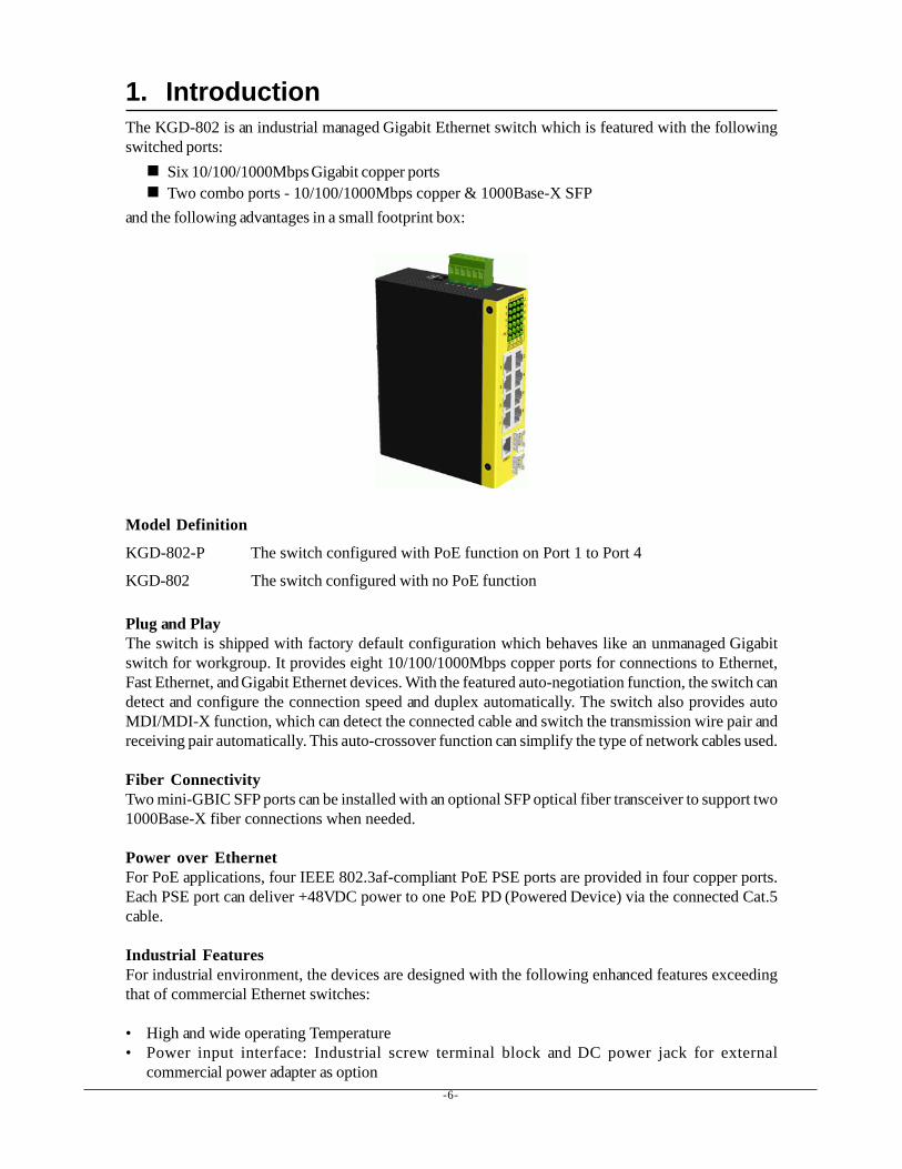
1. IntroductionThe KGD-802 is an industrial managed Gigabit Ethernet switch which is featured with the followingswitched ports:
Six 10/100/1000Mbps Gigabit copper portsTwo combo ports - 10/100/1000Mbps copper & 1000Base-X SFP
and the following advantages in a small footprint box:
Model Definition
KGD-802-P The switch configured with PoE function on Port 1 to Port 4
KGD-802 The switch configured with no PoE function
Plug and PlayThe switch is shipped with factory default configuration which behaves like an unmanaged Gigabitswitch for workgroup. It provides eight 10/100/1000Mbps copper ports for connections to Ethernet,Fast Ethernet, and Gigabit Ethernet devices. With the featured auto-negotiation function, the switch candetect and configure the connection speed and duplex automatically. The switch also provides autoMDI/MDI-X function, which can detect the connected cable and switch the transmission wire pair andreceiving pair automatically. This auto-crossover function can simplify the type of network cables used.
Fiber ConnectivityTwo mini-GBIC SFP ports can be installed with an optional SFP optical fiber transceiver to support two1000Base-X fiber connections when needed.
Power over EthernetFor PoE applications, four IEEE 802.3af-compliant PoE PSE ports are provided in four copper ports.Each PSE port can deliver +48VDC power to one PoE PD (Powered Device) via the connected Cat.5cable.
Industrial FeaturesFor industrial environment, the devices are designed with the following enhanced features exceedingthat of commercial Ethernet switches:
• High and wide operating Temperature• Power input interface: Industrial screw terminal block and DC power jack for external
commercial power adapter as option
-7-
• Screw panel and DIN rail mounting support for industrial enclosure• Industrial-rated Emission and Immunity performance
Web ManagementThe switch is embedded with an Http server which provides management functions for advancednetwork functions including Port Control, Quality of Service, and Virtual LAN functions. The manage-ment can be performed via Web browser based interface over TCP/IP network.
Quality of ServiceFor advanced application, the switch is featured with powerful Quality of Service (QoS) function whichcan classify the priority for received network frames based on the ingress port and frame contents.Furthermore, many service priority policies can be configured for egress operation in per-port basis.
Virtual LAN (VLAN)For increasing Tagged VLAN applications, the switch is also featured with powerful VLAN function tofulfill the up-to-date VLAN requirements. The switch supports both port-based VLAN and taggedVLAN in per-port basis.
802.1x AuthenticationIEEE 802.1X port-based network access control function provide a means of authenticating and autho-rizing devices attached to the switched port that has point-to-point connection characteristics, and ofpreventing access to that port in cases in which the authentication and authorization process fails.
1.1 FeaturesProvides 8 10/100/1000Mbps RJ-45 and two 1000M SFPsProvides four IEEE 802.3af-compliant PoE PSE portsProvides in-band web-based and SNMP management interfaceAll copper ports support auto-negotiation and auto-MDI/MDI-X detectionProvides full wire speed forwardingSupports 802.3x flow control for full-duplex and backpressure for half-duplexProvides port status, statistic monitoring and control functionSupports DHCP IP configurationSupports port-based and 802.1Q Tag-based VLANProvides QoS functionProvides link aggregation (port trunking) function with LACP supportProvides port mirroring functionProvides 802.1X authentication for port accessSupports 802.1w RSTP, 802.1D STP and 802.1S MSTPWatchdog timer functionSupports SFP with Digital Diagnostic Monitoring (DDM)Provides packet storm control functionIn-band embedded firmware upgrade function
-8-
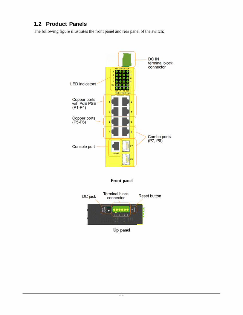
1.2 Product PanelsThe following figure illustrates the front panel and rear panel of the switch:
Front panel
Up panel
-9-
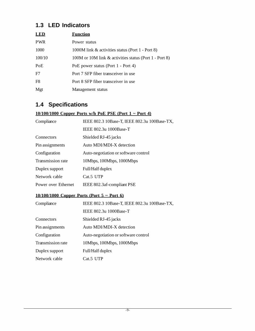
1.3 LED IndicatorsLED Function
PWR Power status
1000 1000M link & activities status (Port 1 - Port 8)
100/10 100M or 10M link & activities status (Port 1 - Port 8)
PoE PoE power status (Port 1 - Port 4)
F7 Port 7 SFP fiber transceiver in use
F8 Port 8 SFP fiber transceiver in use
Mgt Management status
1.4 Specifications10/100/1000 Copper Ports w/h PoE PSE (Port 1 ~ Port 4)
Compliance IEEE 802.3 10Base-T, IEEE 802.3u 100Base-TX,
IEEE 802.3u 1000Base-T
Connectors Shielded RJ-45 jacks
Pin assignments Auto MDI/MDI-X detection
Configuration Auto-negotiation or software control
Transmission rate 10Mbps, 100Mbps, 1000Mbps
Duplex support Full/Half duplex
Network cable Cat.5 UTP
Power over Ethernet IEEE 802.3af-compliant PSE
10/100/1000 Copper Ports (Port 5 ~ Port 6)
Compliance IEEE 802.3 10Base-T, IEEE 802.3u 100Base-TX,
IEEE 802.3u 1000Base-T
Connectors Shielded RJ-45 jacks
Pin assignments Auto MDI/MDI-X detection
Configuration Auto-negotiation or software control
Transmission rate 10Mbps, 100Mbps, 1000Mbps
Duplex support Full/Half duplex
Network cable Cat.5 UTP
-10-
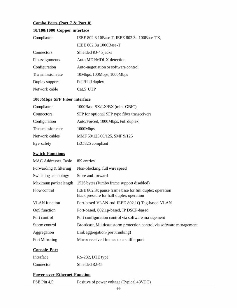
Combo Ports (Port 7 & Port 8)
10/100/1000 Copper interface
Compliance IEEE 802.3 10Base-T, IEEE 802.3u 100Base-TX,
IEEE 802.3u 1000Base-T
Connectors Shielded RJ-45 jacks
Pin assignments Auto MDI/MDI-X detection
Configuration Auto-negotiation or software control
Transmission rate 10Mbps, 100Mbps, 1000Mbps
Duplex support Full/Half duplex
Network cable Cat.5 UTP
1000Mbps SFP Fiber interface
Compliance 1000Base-SX/LX/BX (mini-GBIC)
Connectors SFP for optional SFP type fiber transceivers
Configuration Auto/Forced, 1000Mbps, Full duplex
Transmission rate 1000Mbps
Network cables MMF 50/125 60/125, SMF 9/125
Eye safety IEC 825 compliant
Switch Functions
MAC Addresses Table 8K entries
Forwarding & filtering Non-blocking, full wire speed
Switching technology Store and forward
Maximum packet length 1526 bytes (Jumbo frame support disabled)
Flow control IEEE 802.3x pause frame base for full duplex operationBack pressure for half duplex operation
VLAN function Port-based VLAN and IEEE 802.1Q Tag-based VLAN
QoS function Port-based, 802.1p-based, IP DSCP-based
Port control Port configuration control via software management
Storm control Broadcast, Multicast storm protection control via software management
Aggregation Link aggregation (port trunking)
Port Mirroring Mirror received frames to a sniffer port
Console Port
Interface RS-232, DTE type
Connector Shielded RJ-45
Power over Ethernet Function
PSE Pin 4,5 Positive of power voltage (Typical 48VDC)
-11-
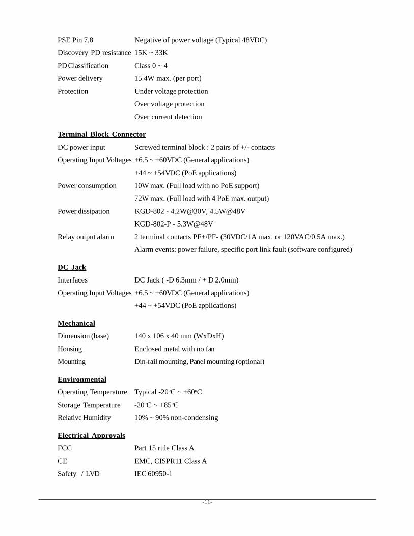
PSE Pin 7,8 Negative of power voltage (Typical 48VDC)
Discovery PD resistance 15K ~ 33K
PD Classification Class 0 ~ 4
Power delivery 15.4W max. (per port)
Protection Under voltage protection
Over voltage protection
Over current detection
Terminal Block Connector
DC power input Screwed terminal block : 2 pairs of +/- contacts
Operating Input Voltages +6.5 ~ +60VDC (General applications)
+44 ~ +54VDC (PoE applications)
Power consumption 10W max. (Full load with no PoE support)
72W max. (Full load with 4 PoE max. output)
Power dissipation KGD-802 - 4.2W@30V, 4.5W@48V
KGD-802-P - 5.3W@48V
Relay output alarm 2 terminal contacts PF+/PF- (30VDC/1A max. or 120VAC/0.5A max.)
Alarm events: power failure, specific port link fault (software configured)
DC Jack
Interfaces DC Jack ( -D 6.3mm / + D 2.0mm)
Operating Input Voltages +6.5 ~ +60VDC (General applications)
+44 ~ +54VDC (PoE applications)
Mechanical
Dimension (base) 140 x 106 x 40 mm (WxDxH)
Housing Enclosed metal with no fan
Mounting Din-rail mounting, Panel mounting (optional)
Environmental
Operating Temperature Typical -20oC ~ +60oC
Storage Temperature -20oC ~ +85oC
Relative Humidity 10% ~ 90% non-condensing
Electrical Approvals
FCC Part 15 rule Class A
CE EMC, CISPR11 Class A
Safety / LVD IEC 60950-1
-12-
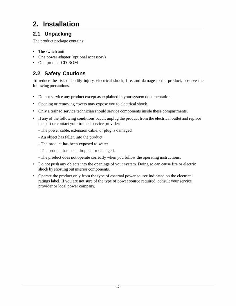
2. Installation2.1 UnpackingThe product package contains:
• The switch unit• One power adapter (optional accessory)• One product CD-ROM
2.2 Safety CautionsTo reduce the risk of bodily injury, electrical shock, fire, and damage to the product, observe thefollowing precautions.
• Do not service any product except as explained in your system documentation.
• Opening or removing covers may expose you to electrical shock.
• Only a trained service technician should service components inside these compartments.
• If any of the following conditions occur, unplug the product from the electrical outlet and replacethe part or contact your trained service provider:- The power cable, extension cable, or plug is damaged.- An object has fallen into the product.- The product has been exposed to water.- The product has been dropped or damaged.- The product does not operate correctly when you follow the operating instructions.
• Do not push any objects into the openings of your system. Doing so can cause fire or electricshock by shorting out interior components.
• Operate the product only from the type of external power source indicated on the electricalratings label. If you are not sure of the type of power source required, consult your serviceprovider or local power company.
-13-
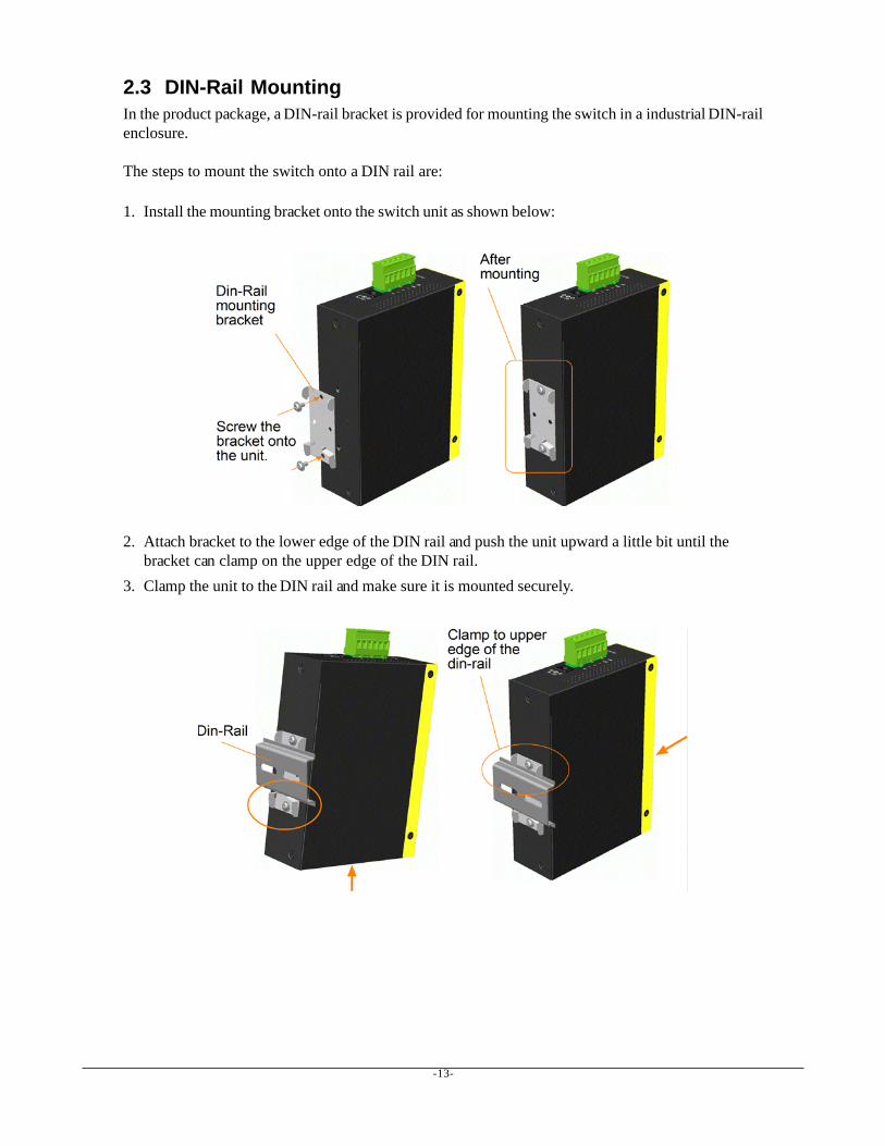
2.3 DIN-Rail MountingIn the product package, a DIN-rail bracket is provided for mounting the switch in a industrial DIN-railenclosure.
The steps to mount the switch onto a DIN rail are:
1. Install the mounting bracket onto the switch unit as shown below:
2. Attach bracket to the lower edge of the DIN rail and push the unit upward a little bit until thebracket can clamp on the upper edge of the DIN rail.
3. Clamp the unit to the DIN rail and make sure it is mounted securely.

-14-
2.4 Panel MountingThe switches are provided with an optional panel mounting bracket. The bracket support mounting theswitch on a plane surface securely. The mounting steps are:
1. Install the mounting bracket on the switch unit.
2. Screw the bracket on the switch unit.3. Screw the switch unit on a panel. Three screw locations are shown below:
-15-
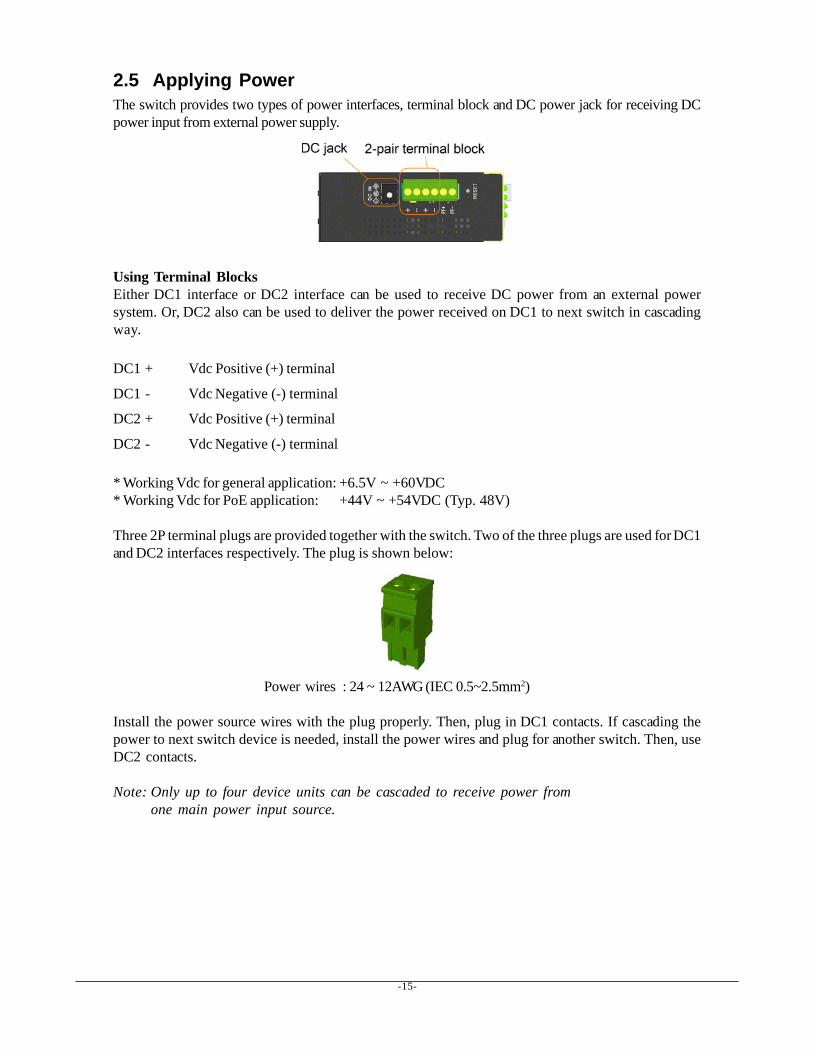
2.5 Applying PowerThe switch provides two types of power interfaces, terminal block and DC power jack for receiving DCpower input from external power supply.
Using Terminal BlocksEither DC1 interface or DC2 interface can be used to receive DC power from an external powersystem. Or, DC2 also can be used to deliver the power received on DC1 to next switch in cascadingway.
DC1 + Vdc Positive (+) terminal
DC1 - Vdc Negative (-) terminal
DC2 + Vdc Positive (+) terminal
DC2 - Vdc Negative (-) terminal
* Working Vdc for general application: +6.5V ~ +60VDC* Working Vdc for PoE application: +44V ~ +54VDC (Typ. 48V)
Three 2P terminal plugs are provided together with the switch. Two of the three plugs are used for DC1and DC2 interfaces respectively. The plug is shown below:
Power wires : 24 ~ 12AWG (IEC 0.5~2.5mm2)
Install the power source wires with the plug properly. Then, plug in DC1 contacts. If cascading thepower to next switch device is needed, install the power wires and plug for another switch. Then, useDC2 contacts.
Note: Only up to four device units can be cascaded to receive power fromone main power input source.
-16-
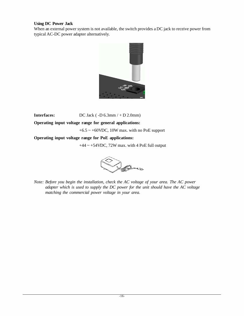
Using DC Power JackWhen an external power system is not available, the switch provides a DC jack to receive power fromtypical AC-DC power adapter alternatively.
Interfaces: DC Jack ( -D 6.3mm / + D 2.0mm)
Operating input voltage range for general applications:
+6.5 ~ +60VDC, 10W max. with no PoE support
Operating input voltage range for PoE applications:
+44 ~ +54VDC, 72W max. with 4 PoE full output
Note: Before you begin the installation, check the AC voltage of your area. The AC poweradapter which is used to supply the DC power for the unit should have the AC voltagematching the commercial power voltage in your area.
-17-
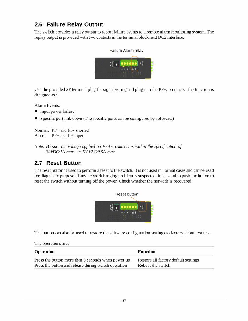
2.6 Failure Relay OutputThe switch provides a relay output to report failure events to a remote alarm monitoring system. Thereplay output is provided with two contacts in the terminal block next DC2 interface.
Use the provided 2P terminal plug for signal wiring and plug into the PF+/- contacts. The function isdesigned as :
Alarm Events:Input power failureSpecific port link down (The specific ports can be configured by software.)
Normal: PF+ and PF- shortedAlarm: PF+ and PF- open
Note: Be sure the voltage applied on PF+/- contacts is within the specification of30VDC/1A max. or 120VAC/0.5A max.
2.7 Reset ButtonThe reset button is used to perform a reset to the switch. It is not used in normal cases and can be usedfor diagnostic purpose. If any network hanging problem is suspected, it is useful to push the button toreset the switch without turning off the power. Check whether the network is recovered.
The button can also be used to restore the software configuration settings to factory default values.
The operations are:
Operation Function
Press the button more than 5 seconds when power up Restore all factory default settingsPress the button and release during switch operation Reboot the switch

-18-
2.8 Making UTP ConnectionsThe 10/100/1000 RJ-45 copper ports supports the following connection types and distances:
Network Cables10BASE-T: 2-pair UTP Cat. 3,4,5 , EIA/TIA-568B 100-ohm100BASE-TX: 2-pair UTP Cat. 5, EIA/TIA-568B 100-ohm1000BASE-T: 4-pair UTP Cat. 5 or higher (Cat.5e is recommended), EIA/TIA-568B 100-ohmLink distance: Up to 100 meters
Auto MDI/MDI-X FunctionThis function allows the port to auto-detect the twisted-pair signals and adapts itself to form a validMDI to MDI-X connection with the remote connected device automatically. No matter a straightthrough cable or crossover cable is connected, the ports can sense the receiving pair automatically andconfigure itself to match the rule for MDI to MDI-X connection. It simplifies the cable installation.
Auto-negotiation FunctionThe ports are featured with auto-negotiation function and full capability to support connection to anyEthernet devices. The port performs a negotiation process for the speed and duplex configuration withthe connected device automatically when each time a link is being established. If the connected deviceis also auto-negotiation capable, both devices will come out the best configuration after negotiationprocess. If the connected device is incapable in auto-negotiation, the switch will sense the speed anduse half duplex for the connection.
Port Configuration ManagementFor making proper connection to an auto-negotiation incapable device, it is suggested to use port con-trol function via software management to set forced mode and specify speed and duplex mode whichmatch the configuration used by the connected device.

-19-
2.9 Making Fiber ConnectionThe SFP slots, F7 and F8 must be installed with an SFP fiber transceiver for making fiber connection.Your switch may come with some SFP transceivers pre-installed when it is shipped.
Installing SFP Fiber TransceiverTo install an SFP fiber transceiver into SFP slot, the steps are:
1. Turn off the power to the switch.2. Insert the SFP fiber transceiver into the SFP slot. Normally, a bail is provided for every SFP
transceiver. Hold the bail and make insertion.3. Until the SFP transceiver is seated securely in the slot, place the bail in lock position.
Connecting Fiber CablesLC connectors are commonly equipped on most SFP transceiver modules. Identify TX and RXconnector before making cable connection. The following figure illustrates a connection examplebetween two fiber ports:
Make sure the Rx-to-Tx connection rule is followed on the both ends of the fiber cable.
Network CablesMultimode (MMF) - 50/125, 62.5/125Single mode (SMF) - 9/125
Fiber Port ConfigurationFor 1000M fiber application on Port 7, 8 just leave the default port configuration Auto for fiber connec-tion.
Note: Since the SFP slot shares the same switched port with RJ-45 connector, make sureonly one network cable type is used any time. In the case of both cable types are usedat the same time, SFP has higher priority.
-20-
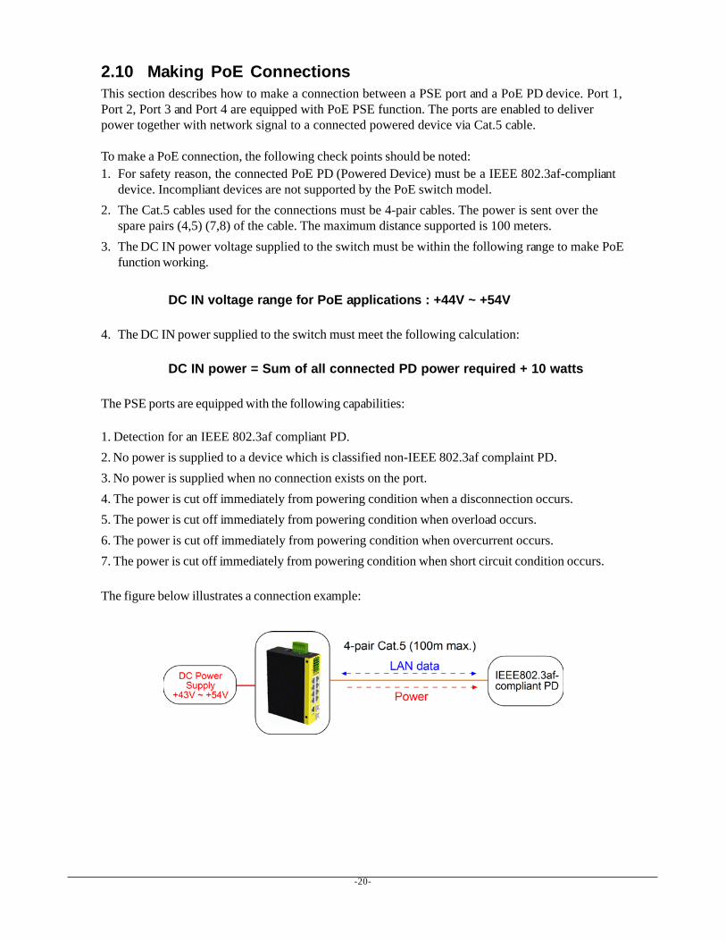
2.10 Making PoE ConnectionsThis section describes how to make a connection between a PSE port and a PoE PD device. Port 1,Port 2, Port 3 and Port 4 are equipped with PoE PSE function. The ports are enabled to deliverpower together with network signal to a connected powered device via Cat.5 cable.
To make a PoE connection, the following check points should be noted:1. For safety reason, the connected PoE PD (Powered Device) must be a IEEE 802.3af-compliant
device. Incompliant devices are not supported by the PoE switch model.2. The Cat.5 cables used for the connections must be 4-pair cables. The power is sent over the
spare pairs (4,5) (7,8) of the cable. The maximum distance supported is 100 meters.3. The DC IN power voltage supplied to the switch must be within the following range to make PoE
function working.
DC IN voltage range for PoE applications : +44V ~ +54V
4. The DC IN power supplied to the switch must meet the following calculation:
DC IN power = Sum of all connected PD power required + 10 watts
The PSE ports are equipped with the following capabilities:
1. Detection for an IEEE 802.3af compliant PD.2. No power is supplied to a device which is classified non-IEEE 802.3af complaint PD.3. No power is supplied when no connection exists on the port.4. The power is cut off immediately from powering condition when a disconnection occurs.5. The power is cut off immediately from powering condition when overload occurs.6. The power is cut off immediately from powering condition when overcurrent occurs.7. The power is cut off immediately from powering condition when short circuit condition occurs.
The figure below illustrates a connection example:
-21-
2.11 LED Indication
LED Function State Interpretation
PWR Power status ON The power is supplied to the switch.OFF The power is not supplied to the switch.
1000 1000Mbps link status ON A 1000M link is established on the port. (No traffic)BLINK Port 1000Mbps link is up and there is traffic.OFF Port link is down.
10/100 1000Mbps link status ON A 10M or 100M link is established on the port.BLINK Port link is up and there is traffic.OFF Port link is down.
PoE PoE power status ON PoE power is delivered on the port.OFF PoE power is off.
F7 Port 7 SFP status ON Port 7 SFP fiber is in use.OFF Port 7 RJ-45 is in use.
F8 Port 8 SFP status ON Port 8 SFP fiber is in use.OFF Port 8 RJ-45 is in use.
Mgt Management status ON System diagnostics & initialization finishedOFF System diagnostics & initialization in process
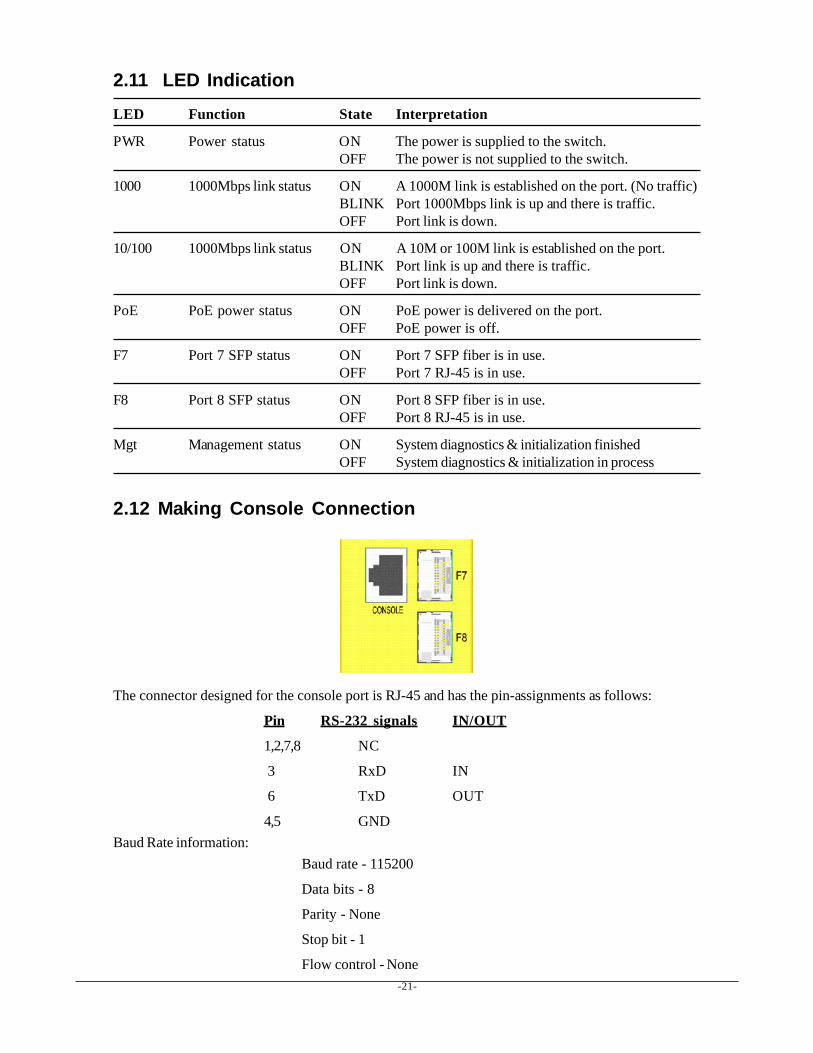
2.12 Making Console Connection
The connector designed for the console port is RJ-45 and has the pin-assignments as follows:
Pin RS-232 signals IN/OUT
1,2,7,8 NC
3 RxD IN
6 TxD OUT
4,5 GNDBaud Rate information:
Baud rate - 115200
Data bits - 8
Parity - None
Stop bit - 1
Flow control - None

-22-
2.12.1 Console CommandsThree command sets are provided as follows:
System commands>System↵System>Info↵ ; display system information
Name: ; System name of this switch unitS/W Version: x.xx ; Software versionH/W Version: x.xx ; Hardware versionMAC address: xx-xx-xx-xx-xx-xx ; MAC address of this switch unit
System>Restore default↵ ; Restore factory default configurationSystem>Restore default keepIP↵ ; Restore defaults, but keep IP no changedSystem>Name [<name>]↵ ; Assign a system name to the switch unitSystem>Reboot↵ ; Reboot the switch unit
Console commands>Console↵Console>Info↵ ; console information
Password: ; password for entering into management interfaceTimeout: ; timeout for console connection without user actionPrompt: ; current command prompt used
Console>Password [<password>]↵ ; change passwordConsole>Timeout [<timeout>]↵ ; change timeout valueConsole>Prompt [<string>]↵ ; change prompt string
IP commands>IP↵IP>Info↵ ; IP information
Address: xxx.xxx.xxx.xxx ; IP addressSubnet Mask: xxx.xxx.xxx.xxx ; Subnet maskGateway: xxx.xxx.xxx.xxx ; Gateway IP addressDhcp: disabled ; Gateway IP address
IP>Setup [<ipaddress>[<ipmask>[<ipgateway>]]]↵ ; Setup new IPIP>Status↵ ; DHCP status when enabled
Dynamic Address:xxx.xxx.xxx.xxx Subnet Mask: xxx.xxx.xxx.xxxGateway: xxx.xxx.xxx.xxx dhcp Address: xxx.xxx.xxx.xxx
IP>Dhcp [enable / disable]↵ ; Use DHCP mode or not
-23-
2.13 Configuring IP Address and Password for the SwitchThe switch is shipped with the following factory default settings for software management :
Default IP address of the switch : 192.168.0.2 / 255.255.255.0
The IP Address is an identification of the switch in a TCP/IP network. Each switch should be desig-nated a new and unique IP address in the network. Two methods to configure the IP address are:
1. Use console port
The console command sequence to set a fixed IP for the switch is:>IP↵IP>Setup [<ipaddress>[<ipmask>[<ipgateway>]]]↵
The console command sequence to use DHCP mode for IP is:>IP↵IP>Dhcp enable↵IP>
2. Use Web management
Refer to Web management interface for System Configuration. The switch is shipped withfactory default password 123 for software management. The password is used for authenticationin accessing to the switch via Http web-based interface. For security reason, it is recommended tochange the default settings for the switch before deploying it to your network. Refer to Webmanagement interface for System Configuration.
-24-
3. Advanced FunctionsTo help a better understanding about the software management interfaces, this chapter describes someadvanced functions provided by the switch.
3.1 AbbreviationIngress Port : Ingress port is the input port on which a packet is received.
Egress Port : Egress port is the output port from which a packet is sent out.
IEEE 802.1Q Packets : A packet which is embedded with a VLAN Tag field
VLAN Tag : In IEEE 802.1Q packet format, 4-byte tag field is inserted in the original Ethernet framebetween the Source Address and Type/Length fields. The tag is composed of :
#of bits 16 3 1 12Frame field TPID User priority CFI VID
TPID : 16-bit field is set to 0x8100 to identify a frame as an IEEE 802.1Q tagged packet
User Priority : 3-bit field refer to the 802.1p priority
CFI : The Canonical Format Indicator for the MAC address is a 1 bit field.
VID : VLAN identifier, 12-bit field identifies the VLAN to which the frame belongs to.
Untagged packet : A standard Ethernet frame with no VLAN Tag field
Priority-tagged packet : An IEEE 802.1Q packet which VID filed value is zero (VID=0)
VLAN-Tagged packet : An IEEE 802.1Q packet which VID filed value is not zero (VID<>0)
PVID (Port VID)PVID is the default VID of an ingress port. It is often used in VLAN classification for untaggedpackets. It is also often used for egress tagging operation.
DSCP : Differentiated Service Code Point, 6-bit value field in an IP packet
VLAN Table lookup : The process of searching VLAN table to find a VLAN which matches thegiven VID index
MAC address table lookup : The process of searching MAC address table to find a MAC entrywhich matches the given destination MAC address and the port where the MAC address is located
Packet forwarding : also known as packet switching in a network switch based on MAC addresstable and VLAN table information
VLAN forwarding : the operation that a packet is forwarded to an egress destination port based onVLAN table information
VLAN group : configuration information about a VLAN which can be recognized in the switch. Theinformation includes a VID associated to the VLAN, member ports, and some special settings.
-25-
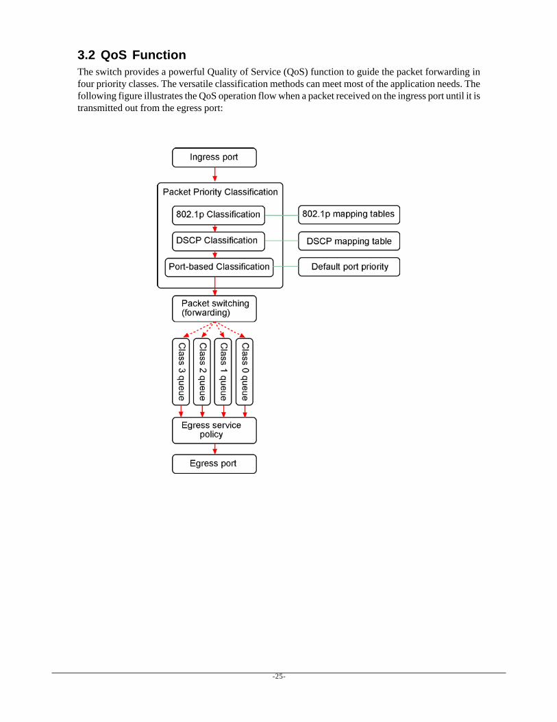
3.2 QoS FunctionThe switch provides a powerful Quality of Service (QoS) function to guide the packet forwarding infour priority classes. The versatile classification methods can meet most of the application needs. Thefollowing figure illustrates the QoS operation flow when a packet received on the ingress port until it istransmitted out from the egress port:

-26-
3.2.1 Packet Priority ClassificationEach received packet is examined and classified into one of four priority classes, Class 3, Class 2,Class 1 and Class 0 upon reception. The switch provides the following classification methods:
802.1p classification : use User Priority tag value in the received IEEE 802.1Q packet to map to onepriority classDSCP classification : use DSCP value in the received IP packet to map to one priority classPort-based classification : used when 802.1p and DSCP are disabled or fail to be applied
They all can be configured to be activated or not. More than one classification methods can be enabledat the same time. However, 802.1p classification is superior than DSCP classification.
802.1p mapping tables : Each ingress port has its own mapping table for 802.1p classification.DSCP mapping table : All ingress ports share one DSCP mapping table for DSCP classification.Default port priority : A port default priority class is used when port-based classification is applied
All configuration settings are in per port basis except that DSCP mapping table is global to all ports. Areceived packet is classified into one of four priority class before it is forwarded to an egress port.
3.2.2 Priority Class QueuesEach egress port in the switch is equipped with four priority class egress queues to store the packetsfor transmission. A packet is stored into the class queue which is associated to the classified priorityclass. For example, a packet is stored into Class 3 egress queue if it is classified as priority Class 3.
3.2.3 Egress Service PolicyEach port can be configured with an egress service policy to determine the transmission priority amongfour class queues. By default, higher class number has higher priority than the lower class numbers.
Four policies are provided for selection as follows:
• Strict priority : Packets in high priority class queue are sent first until the queue is empty• Weighted ratio priority Class 3:2:1:0 = 4:3:2:1 : four queues are served in 4:3:2:1 ratio• Weighted ratio priority Class 3:2:1:0 = 5:3:1:1 : four queues are served in 5:3:1:1 ratio• Weighted ratio priority Class 3:2:1:0 = 1:1:1:1 : four queues are served equally
Strict priority policy lets high priority class queue is served first until it is empty. Lower priority queuemay not get any service (or egress bandwidth) when higher priority traffic is heavy for long time. Threeweighted ratio policies are provided to resolve such problem. Four class queues are served in weightedround robin basis. Every priority class can get a guaranteed ratio for the egress bandwidth.
-27-
3.3 VLAN FunctionThe switch supports port-based VLAN, 802.1Q Tag VLAN and eight VLAN groups.
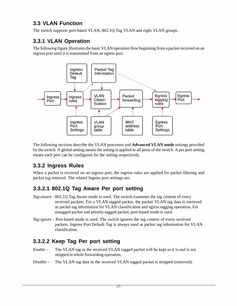
3.3.1 VLAN OperationThe following figure illustrates the basic VLAN operation flow beginning from a packet received on aningress port until it is transmitted from an egress port.
The following sections describe the VLAN processes and Advanced VLAN mode settings providedby the switch. A global setting means the setting is applied to all ports of the switch. A per port settingmeans each port can be configured for the setting respectively.
3.3.2 Ingress RulesWhen a packet is received on an ingress port, the ingress rules are applied for packet filtering andpacket tag removal. The related Ingress port settings are:
3.3.2.1 802.1Q Tag Aware Per port settingTag-aware -802.1Q Tag Aware mode is used. The switch examines the tag content of every
received packets. For a VLAN tagged packet, the packet VLAN tag data is retrievedas packet tag information for VLAN classification and egress tagging operation. Foruntagged packet and priority-tagged packet, port-based mode is used.
Tag-ignore - Port-based mode is used. The switch ignores the tag content of every receivedpackets. Ingress Port Default Tag is always used as packet tag information for VLANclassification.
3.3.2.2 Keep Tag Per port settingEnable - The VLAN tag in the received VLAN tagged packet will be kept as it is and is not
stripped in whole forwarding operation.
Disable - The VLAN tag data in the received VLAN tagged packet is stripped (removed).
-28-
3.3.2.3 Drop Untag Per Port SettingEnable - All untagged packets and priority-tagged packets are dropped. A priority-tagged packet
is treated as an untagged packet in this switch. Only VLAN-tagged packets areadmitted.
Disable - Disable Untagged packet filtering
3.3.2.4 Drop Tag Per Port SettingEnable - All VLAN-tagged packets are dropped. A priority-tagged packet is treated as an
untagged packet in this switch. Only untagged packets are admitted.
Disable - Disable VLAN-tagged packet filtering
3.3.3 Ingress Default Tag Per Port SettingEach port can be configured with one Ingress Default Tag. This ingress port default tag is used wheningress port is in Tag-ignore mode or for the received untagged packets in Tag-aware mode. TheIngress Default Tag includes PVID, CFI and User Priority configuration.
When Ingress port default tag is used, it is copied as packet associated Packet Tag Information forVLAN classification. The PVID is used as index to one VLAN group in VLAN group table.
3.3.4 Packet Tag InformationUnder VLAN process, every packet is associated with one Packet Tag information in packet forward-ing operation. The tag information includes VID, CFI and User Priority data and is used for twopurposes:
• The VID in tag is used as index for VLAN classification.• The tag is used for egress tag insertion if egress tagging is enabled.
The following table lists how the Packet Tag information is generated:
Tag Aware setting Received Packet Type Packet Tag information sourceTag-ignore Untagged packet Ingress Port Default TagTag-ignore Priority-tagged packet Ingress Port Default TagTag-ignore VLAN-tagged packet Ingress Port Default Tag
Tag-aware Untagged packet Ingress Port Default TagTag-aware Priority-tagged packet Ingress Port Default TagTag-aware VLAN-tagged packet Received packet VLAN Tag
-29-
3.3.5 VLAN Group Table ConfigurationThe switch provides a table of eight VLAN groups to support up to eight VLANs at the same time.Each VLAN group is associated to one unique VLAN. The table is referred for VLAN classification.
A VLAN group contains the following configuration settings:
VID : 12-bit VLAN Identifier index to the VLAN to which the group is associatedMember Ports : the admitted egress ports for packets belonging to this VLANSource Port Check : the ingress port of the packet must also be the member port of this VLAN.Otherwise, the packet is discarded.
3.3.6 VLAN ClassificationVLAN classification is a process to classify a VLAN group to which a received packet belongs. TheVID of the generated Packet Tag information associated to the received packet is used as an index forVLAN group table lookup. The VID matched VLAN group will be used for packet forwarding. If nomatched VLAN group is found in table lookup, the packet is dropped.
Refer to section 3.2.4 for details about how the Packet Tag information is generated.
The member ports specified in the matched VLAN group are the admitted egress port range for thepacket. The packet will never be forwarded to other ports which are not in the member ports.
The Source Port Check setting of the matched VLAN group is also referred. If it is enabled, theingress port will be checked whether it is a member port of this group.
3.3.7 Packet ForwardingThe forwarding is a process to forward the received packet to one or more egress ports. The processuses the following information as forwarding decision:
• Member ports of the matched VLAN group : the egress port range for forwarding• Source Port Check setting of the matched VLAN group : check ingress port membership• The packet destination MAC address : for MAC address table loop up• The switch MAC address table : to find the associated port where a MAC address is learned
If the MAC address table lookup is matched and the learned port is the VLAN member port, thepacket is forwarded to the port (egress port). If the lookup failed, the switch will broadcast the packetto all member ports.
-30-
3.3.8 Egress Tagging RulesEgress Tagging rules are used to make change to the packet before it is stored into egress queue of anegress port. Three egress settings are provided for each port and are described as follows:
3.3.8.1 Egress SettingsInsert Tag (per port setting)Enable - Insert the Tag data of the associated Packet Tag information into the packet
Disable - No tagging is performed.
Untagging Specific VID (per port setting)Enable - No tag insertion if the VID data of the associated Packet Tag information matches the
Untagged VID configured in next setting even [Insert Tag] is enabled.
Disable - This rule is not applied.
3.3.9 Summary of VLAN FunctionVLAN ModesPort-based VLAN Mode : simple port-based 2-VLAN-groups modePort-based VLAN ISP Mode : simple port-based 5-VLAN-groups modeAdvanced VLAN Mode : Full VLAN configuration for port-based and Tag-based VLAN
Advanced VLAN ModeEgress Settings (per port) : [Tag Aware], [Keep Tag], [Drop Untag], [Drop Tag]Ingress Default Tag (per port) : [PVID], [CFI], [User Priority]VLAN Groups (global) : 8 VLAN groupsVLAN Group Settings (per group) : [VID], [Member Ports], [Source Port Check]Egress Settings : [Insert Tag], [Untagging Specific VID], [Untagged VID]
VLAN range supported : 1 ~ 4095 (eight VLANs at the same time)
[PVID] [VID] [Untagged VID] value range : 1 ~ 4095
3.4 802.1X AuthenticationFor some IEEE 802 LAN environments, it is desirable to restrict access to the services offered by theLAN to those users and devices that are permitted to make use of those services. IEEE 802.1X Port-based network access control function provide a means of authenticating and authorizing devices at-tached to a LAN port that has point-to-point connection characteristics, and of preventing access to thatport in cases in which the authentication and authorization process fails. The 802.1X standard relies onthe client to provide credentials in order to gain access to the network. The credentials are not based ona hardware address. Instead, they can be either a username/password combination or a certificate. Thecredentials are not verified by the switch but are sent to a Remote Authentication Dial-In User Service(RADIUS) server, which maintains a database of authentication information. 802.1X consists of threecomponents for authentication exchange, which are as follows:

-31-
An 802.1X authenticator: This is the port on the switch that has services to offer to an end device,provided the device supplies the proper credentials.
An 802.1X supplicant: This is the end device; for example, a PC that connects to a switch that isrequesting to use the services (port) of the device. The 802.1X supplicant must be able to respond tocommunicate.
An 802.1X authentication server: This is a RADIUS server that examines the credentials provided tothe authenticator from the supplicant and provides the authentication service. The authentication server is respon-sible for letting the authenticator know if services should be granted.
The 802.1X authenticator operates as a go-between with the supplicant and the authentication server toprovide services to the network. When a switch is configured as an authenticator, the ports of theswitch must then be configured for authorization. In an authenticator-initiated port authorization, a clientis powered up or plugs into the port, and the authenticator port sends an Extensible AuthenticationProtocol (EAP) PDU to the supplicant requesting the identification of the supplicant. At this point in theprocess, the port on the switch is connected from a physical standpoint; however, the 802.1X processhas not authorized the port and no frames are passed from the port on the supplicant into the switchingengine. If the PC attached to the switch did not understand the EAP PDU that it was receiving from theswitch, it would not be able to send an ID and the port would remain unauthorized. In this state, the portwould never pass any user traffic and would be as good as disabled. If the client PC is running the802.1X EAP, it would respond to the request with its configured ID. (This could be a username/password combination or a certificate.)
After the switch, the authenticator receives the ID from the PC (the supplicant). The switch thenpasses the ID information to an authentication server (RADIUS server) that can verify the identifica-tion information. The RADIUS server responds to the switch with either a success or failure message.If the response is a success, the port will be authorized and user traffic will be allowed to pass throughthe port like any switch port connected to an access device. If the response is a failure, the port willremain unauthorized and, therefore, unused. If there is no response from the server, the port will alsoremain unauthorized and will not pass any traffic.
-32-
4. Web ManagementThe switch features an http server which can serve the management requests coming from any webbrowser software over TCP/IP network.
Web BrowserCompatible web browser software with JAVA script supportMicrosoft Internet Explorer 4.0 or laterNetscape Communicator 4.x or later
Set IP Address for the System UnitBefore the switch can be managed from a web browser software, make sure a unique IP address isconfigured for the switch.
4.1 Start Browser Software and Making ConnectionStart your browser software and enter the IP address of the switch unit to which you want to connect.The IP address is used as URL for the browser software to search the device.
URL : http://xxx.xxx.xxx.xxx/
Factory default IP address : 192.168.0.2
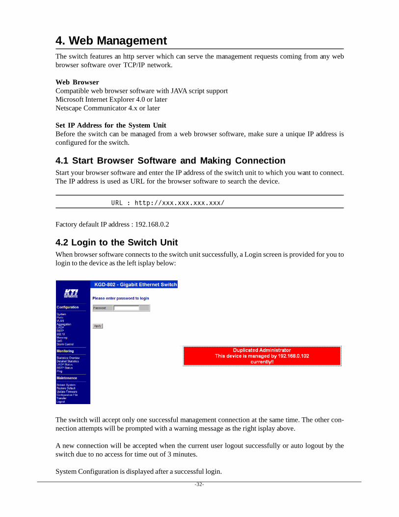
4.2 Login to the Switch UnitWhen browser software connects to the switch unit successfully, a Login screen is provided for you tologin to the device as the left isplay below:
The switch will accept only one successful management connection at the same time. The other con-nection attempts will be prompted with a warning message as the right isplay above.
A new connection will be accepted when the current user logout successfully or auto logout by theswitch due to no access for time out of 3 minutes.
System Configuration is displayed after a successful login.
-33-
4.3 Main Management Menu
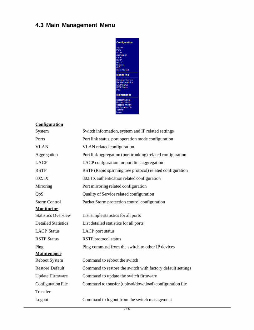
ConfigurationSystem Switch information, system and IP related settings
Ports Port link status, port operation mode configuration
VLAN VLAN related configuration
Aggregation Port link aggregation (port trunking) related configuration
LACP LACP confguration for port link aggregation
RSTP RSTP (Rapid spanning tree protocol) related configuration
802.1X 802.1X authentication related configuration
Mirroring Port mirroring related configuration
QoS Quality of Service related configuration
Storm Control Packet Storm protection control configurationMonitoringStatistics Overview List simple statistics for all ports
Detailed Statistics List detailed statistics for all ports
LACP Status LACP port status
RSTP Status RSTP protocol status
Ping Ping command from the switch to other IP devicesMaintenanceReboot System Command to reboot the switch
Restore Default Command to restore the switch with factory default settings
Update Firmware Command to update the switch firmware
Configuration File Command to transfer (upload/download) configuration file
Transfer
Logout Command to logout from the switch management
-34-
4.4 System
-35-
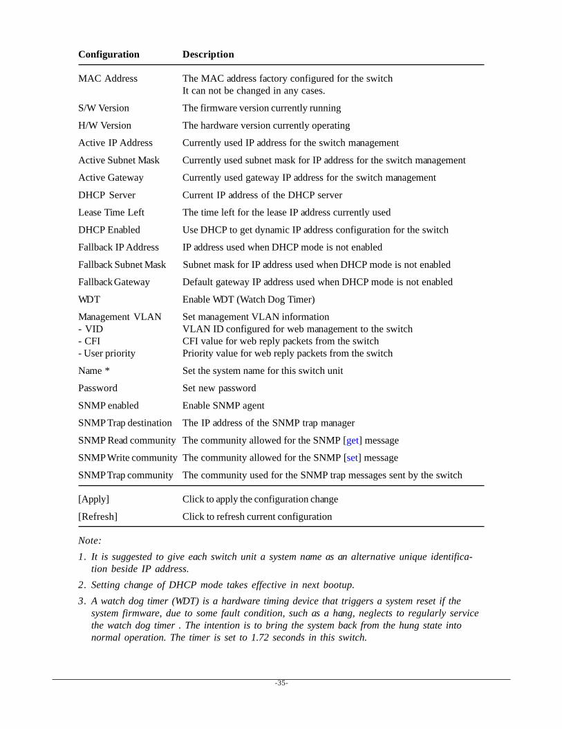
Configuration Description
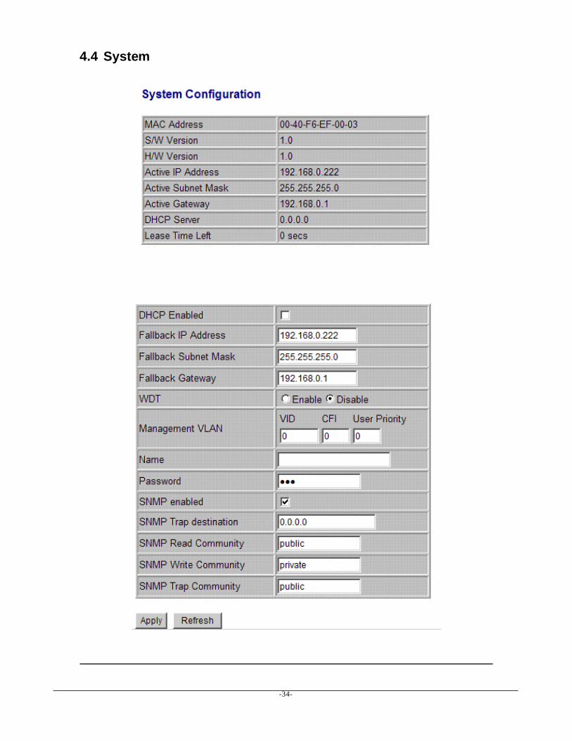
MAC Address The MAC address factory configured for the switchIt can not be changed in any cases.
S/W Version The firmware version currently running
H/W Version The hardware version currently operating
Active IP Address Currently used IP address for the switch management
Active Subnet Mask Currently used subnet mask for IP address for the switch management
Active Gateway Currently used gateway IP address for the switch management
DHCP Server Current IP address of the DHCP server
Lease Time Left The time left for the lease IP address currently used
DHCP Enabled Use DHCP to get dynamic IP address configuration for the switch
Fallback IP Address IP address used when DHCP mode is not enabled
Fallback Subnet Mask Subnet mask for IP address used when DHCP mode is not enabled
Fallback Gateway Default gateway IP address used when DHCP mode is not enabled
WDT Enable WDT (Watch Dog Timer)
Management VLAN Set management VLAN information- VID VLAN ID configured for web management to the switch- CFI CFI value for web reply packets from the switch- User priority Priority value for web reply packets from the switch
Name * Set the system name for this switch unit
Password Set new password
SNMP enabled Enable SNMP agent
SNMP Trap destination The IP address of the SNMP trap manager
SNMP Read community The community allowed for the SNMP [get] message
SNMP Write community The community allowed for the SNMP [set] message
SNMP Trap community The community used for the SNMP trap messages sent by the switch
[Apply] Click to apply the configuration change
[Refresh] Click to refresh current configuration
Note:1. It is suggested to give each switch unit a system name as an alternative unique identifica-
tion beside IP address.2. Setting change of DHCP mode takes effective in next bootup.3. A watch dog timer (WDT) is a hardware timing device that triggers a system reset if the
system firmware, due to some fault condition, such as a hang, neglects to regularly servicethe watch dog timer . The intention is to bring the system back from the hung state intonormal operation. The timer is set to 1.72 seconds in this switch.
-36-
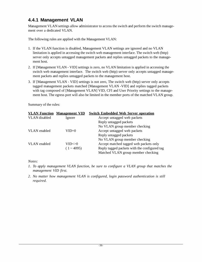
4.4.1 Management VLANManagement VLAN settings allow administrator to access the switch and perform the switch manage-ment over a dedicated VLAN.
The following rules are applied with the Management VLAN:
1. If the VLAN function is disabled, Management VLAN settings are ignored and no VLANlimitation is applied in accessing the switch web management interface. The switch web (http)server only accepts untagged management packets and replies untagged packets to the manage-ment host.
2. If [Management VLAN - VID] settings is zero, no VLAN limitation is applied in accessing theswitch web management interface. The switch web (http) server only accepts untagged manage-ment packets and replies untagged packets to the management host.
3. If [Management VLAN - VID] settings is not zero, The switch web (http) server only acceptstagged management packets matched [Management VLAN -VID] and replies tagged packetswith tag composed of [Management VLAN] VID, CFI and User Priority settings to the manage-ment host. The egress port will also be limited in the member ports of the matched VLAN group.
Summary of the rules:
VLAN Function Management VID Switch Embedded Web Server operationVLAN disabled Ignore Accept untagged web packets
Reply untagged packetsNo VLAN group member checking
VLAN enabled VID=0 Accept untagged web packetsReply untagged packetsNo VLAN group member checking
VLAN enabled VID<>0 Accept matched tagged web packets only( 1 ~ 4095) Reply tagged packets with the configured tag
Matched VLAN group member checking
Notes:1. To apply management VLAN function, be sure to configure a VLAN group that matches the
management VID first.2. No matter how management VLAN is configured, login password authentication is still
required.

-37-
4.5 Ports
Configuration Function
Enable Jumbo Frames Select to enable jumbo frame support
Port The port numberEx.7 Indicates Port 7 type - RJ-457(SFP) Indicates Port 7 type - SFP8 Indicates Port 8 type - RJ-458(SFP) Indicates Port 8 type - SFP
Link Speed and duplex status with green background - port is link onDown with red background - port is link down
Mode Select port operating modeDisabled - disable the port operationMode Auto-negotiation Speed capability Duplex capabilityAuto Enable 10, 100, 1000M Full, Half10 Half Disable 10M Half10 Full Disable 10M Full100 Half Disable 100M Half100 Full Disable 100M Full1000 Full Enable 1000M FullAuto 1000 Full Enable 1000M FullForce 1000 Full Disable 1000M Full
-38-
Flow Control Set port flow control functionv - set to enable 802.3x pause flow control for ingress and egress
Relay Alarm Set port link down alarmv - set to enable port link down monitoring for failure relay output
(Refer to section 2.6 for Failure Relay Output function.)
PoE Enable Set port PoE function (Only valid for Port 1 ~ Port 4 on PoE model)v - set to enable PoE function
[SFP DDM] Click to display DDM information and status of the SFP transceivers
[Port Type] Click to set port type, RJ-45 or SFP for Port 7 and Port 8
[Apply] Click to apply the configuration change
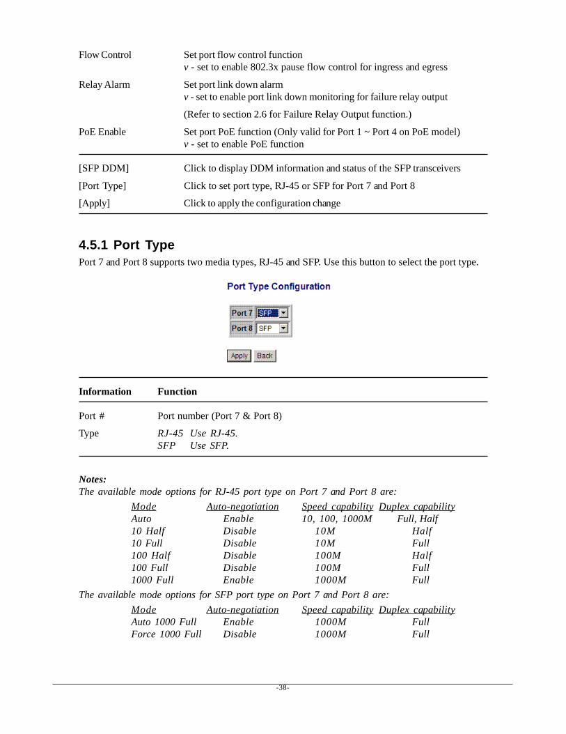
4.5.1 Port TypePort 7 and Port 8 supports two media types, RJ-45 and SFP. Use this button to select the port type.
Information Function
Port # Port number (Port 7 & Port 8)
Type RJ-45 Use RJ-45.SFP Use SFP.
Notes:The available mode options for RJ-45 port type on Port 7 and Port 8 are:
Mode Auto-negotiation Speed capability Duplex capabilityAuto Enable 10, 100, 1000M Full, Half10 Half Disable 10M Half10 Full Disable 10M Full100 Half Disable 100M Half100 Full Disable 100M Full1000 Full Enable 1000M Full
The available mode options for SFP port type on Port 7 and Port 8 are:Mode Auto-negotiation Speed capability Duplex capabilityAuto 1000 Full Enable 1000M FullForce 1000 Full Disable 1000M Full

-39-
4.5.2 SFP DDM StatusDDM (Digital Diagnostic Monitoring) information and status are provided in some SFP transceivers.Part of the information are retrieved and listed as follows:
Information Function
Port Port number which has SFP slot (Port 4, Port 5, Port 6 come with SFP.)
Identifier The identifier information of the transceiver
Connector The connector type used on the transceiver
SONET Compliance SONET compliance information of the transceiver
GbE Compliance Gigabit Ethernet compliance information of the transceiver
Vendor Name The vendor name of the transceiver
Vendor OUI The vendor OUI of the transceiver
Temperature The current temperature sensed inside the transceiver
Voltage The working voltage sensed inside the transceiver
TX Power The transmission optical power sensed
[Refresh] Click to refresh current configuration
[Back] Click to back to previous page
Note:1. TX power data is displayed with unit of mW. It can be converted to dBm as remark.2. N/A: the information is not available
-40-
4.6 VLANs
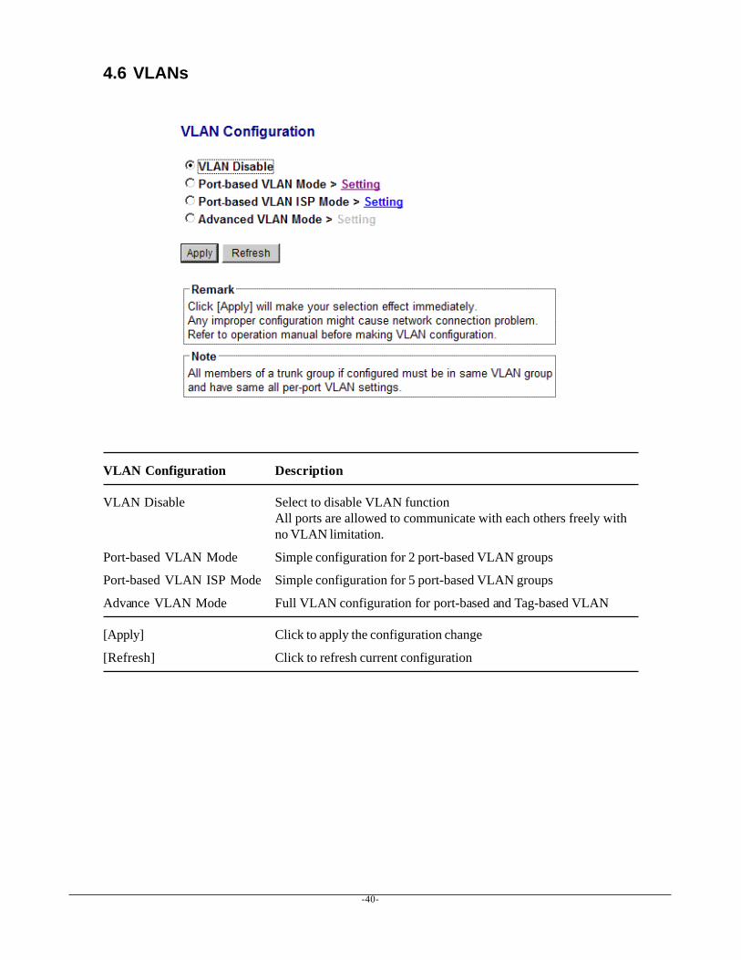
VLAN Configuration Description
VLAN Disable Select to disable VLAN functionAll ports are allowed to communicate with each others freely withno VLAN limitation.
Port-based VLAN Mode Simple configuration for 2 port-based VLAN groups
Port-based VLAN ISP Mode Simple configuration for 5 port-based VLAN groups
Advance VLAN Mode Full VLAN configuration for port-based and Tag-based VLAN
[Apply] Click to apply the configuration change
[Refresh] Click to refresh current configuration

-41-
4.6.1 Port-based VLAN Mode
Configuration Description
Group 1, 2 Port-based VLAN group number
Member ports Select member ports for the group
[Apply] Click to apply the configuration change
[Refresh] Click to refresh current configuration
[Back] Click to go back to upper menu
Operation in this mode:1. The member ports of two groups are allowed to overlap.2. The member ports in same group can communicate with other members only.3. No packet tag is examined.4. A received packet will not be modified (i.e. tagging or untagging) through VLAN operation till it
is transmitted.
-42-
4.6.2 Port-based VLAN ISP Mode
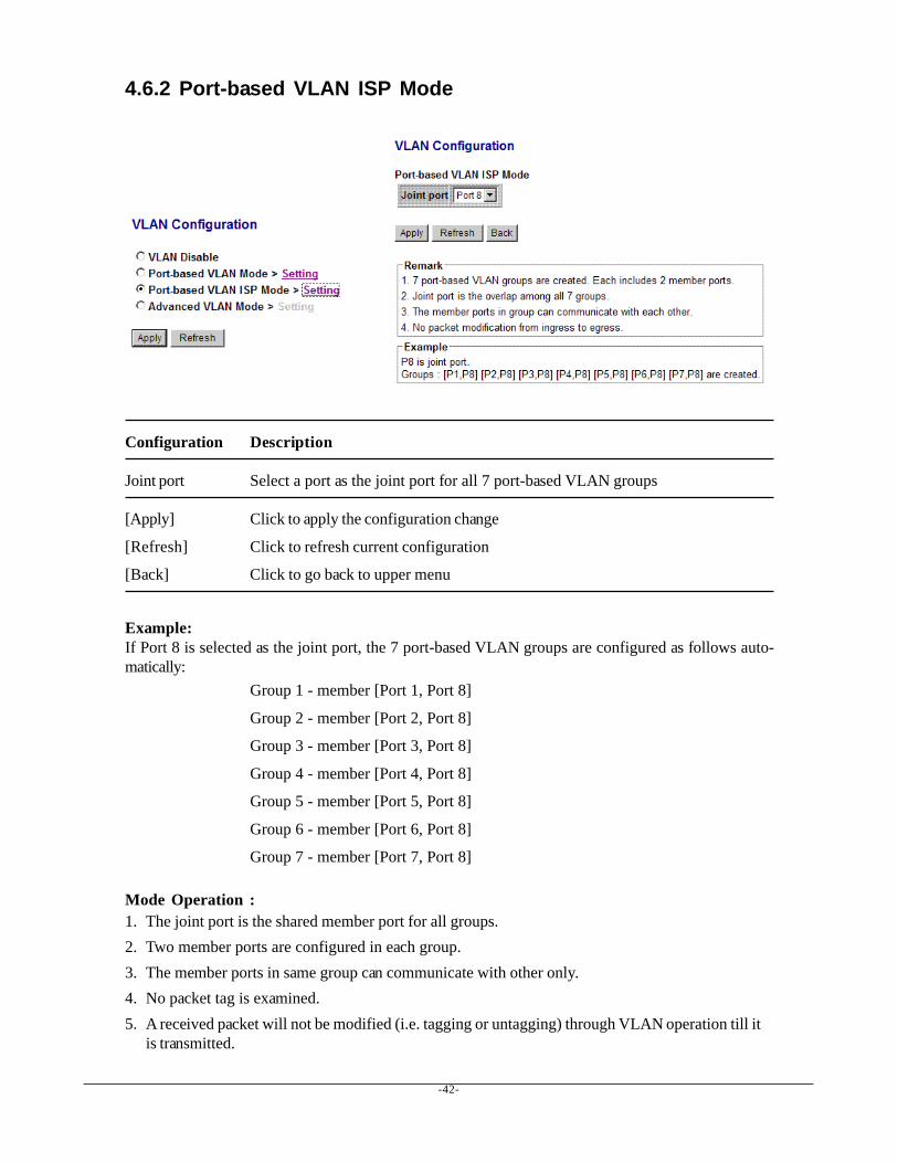
Configuration Description
Joint port Select a port as the joint port for all 7 port-based VLAN groups
[Apply] Click to apply the configuration change
[Refresh] Click to refresh current configuration
[Back] Click to go back to upper menu
Example:If Port 8 is selected as the joint port, the 7 port-based VLAN groups are configured as follows auto-matically:
Group 1 - member [Port 1, Port 8]
Group 2 - member [Port 2, Port 8]
Group 3 - member [Port 3, Port 8]
Group 4 - member [Port 4, Port 8]
Group 5 - member [Port 5, Port 8]
Group 6 - member [Port 6, Port 8]
Group 7 - member [Port 7, Port 8]
Mode Operation :1. The joint port is the shared member port for all groups.2. Two member ports are configured in each group.3. The member ports in same group can communicate with other only.4. No packet tag is examined.5. A received packet will not be modified (i.e. tagging or untagging) through VLAN operation till it
is transmitted.
-43-
4.6.3 Advanced VLAN Mode
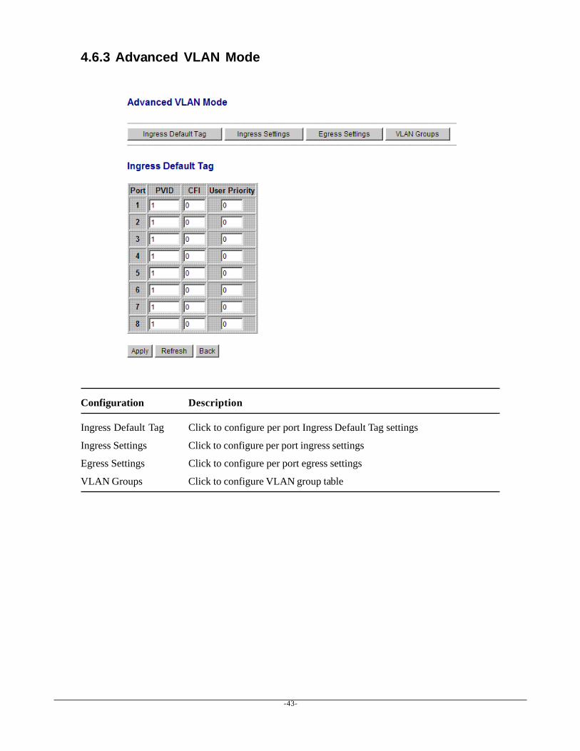
Configuration Description
Ingress Default Tag Click to configure per port Ingress Default Tag settings
Ingress Settings Click to configure per port ingress settings
Egress Settings Click to configure per port egress settings
VLAN Groups Click to configure VLAN group table
-44-
4.6.3.1 Ingress Default Tag
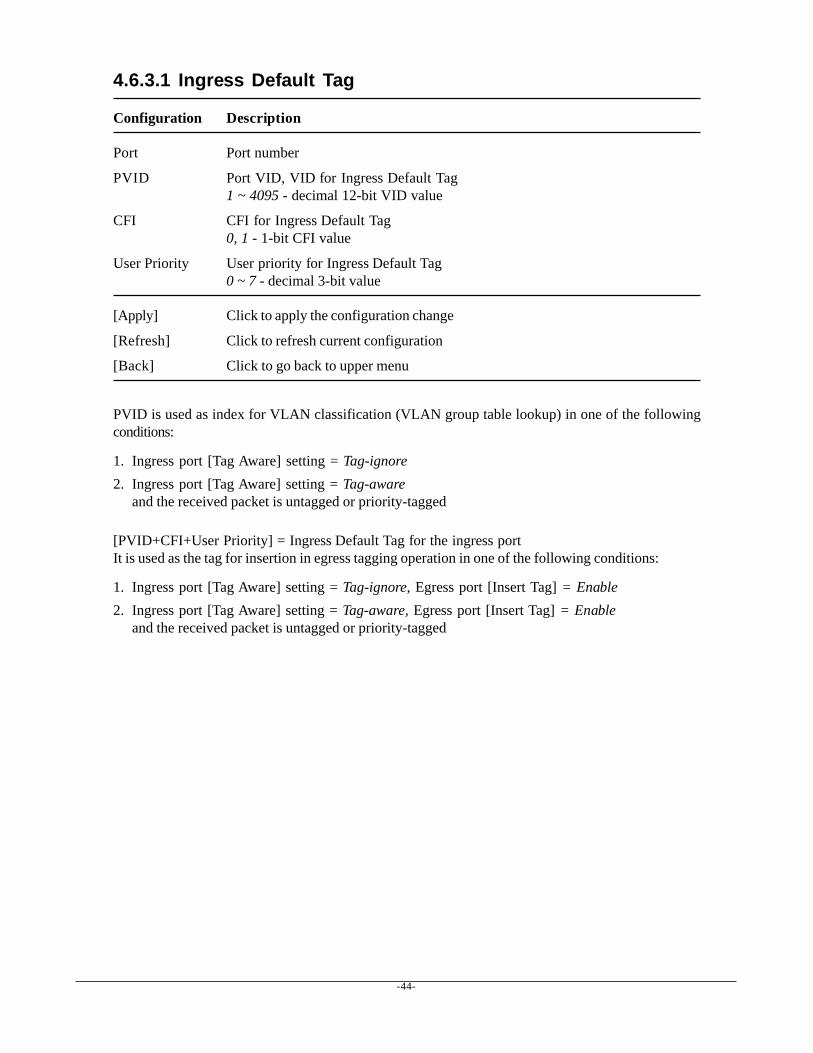
Configuration Description
Port Port number
PVID Port VID, VID for Ingress Default Tag1 ~ 4095 - decimal 12-bit VID value
CFI CFI for Ingress Default Tag0, 1 - 1-bit CFI value
User Priority User priority for Ingress Default Tag0 ~ 7 - decimal 3-bit value
[Apply] Click to apply the configuration change
[Refresh] Click to refresh current configuration
[Back] Click to go back to upper menu
PVID is used as index for VLAN classification (VLAN group table lookup) in one of the followingconditions:
1. Ingress port [Tag Aware] setting = Tag-ignore2. Ingress port [Tag Aware] setting = Tag-aware
and the received packet is untagged or priority-tagged
[PVID+CFI+User Priority] = Ingress Default Tag for the ingress portIt is used as the tag for insertion in egress tagging operation in one of the following conditions:
1. Ingress port [Tag Aware] setting = Tag-ignore, Egress port [Insert Tag] = Enable2. Ingress port [Tag Aware] setting = Tag-aware, Egress port [Insert Tag] = Enable
and the received packet is untagged or priority-tagged

-45-
4.6.3.2 Ingress Settings
Configuration Description
Port Port number
Tag Aware Check tag data for every received packetTag-aware - set to activate Tag-based modeTag-ignore - set to use port-based mode and ignore any tag in packet
Keep Tag Tag is removed from the received packet if existsEnable - set to activate tag removal for VLAN-tagged packetsDisable - set to disable tag removal function
Drop Untag Drop all untagged packets and priority-tagged packetsEnable - drop untagged packets and priority-tagged packetsDisable - admit untagged packets and priority-tagged packets
Drop Tag Drop all VLAN-tagged packetsEnable - drop VLAN-tagged packetsDisable - admit VLAN-tagged packets
[Apply] Click to apply the configuration change
[Refresh] Click to refresh current configuration
Note:1. Priority-tagged packet (VID=0) is treated as untagged packet in the switch.2. [Tag Aware] setting affects the index used for VLAN classification (VLAN table lookup).
The following table lists the index used:
Ingress [Tag Aware] settingReceived packet type Tag-ignore Tag-awareUntagged PVID PVIDPriority-tagged (VID=0) PVID PVIDVLAN-tagged (VID>0) PVID Packet tag VID
3. Both [Drop Untag] and [Drop Tag] are set to Disable to admit all packets.
-46-
4.6.3.3 Egress Settings
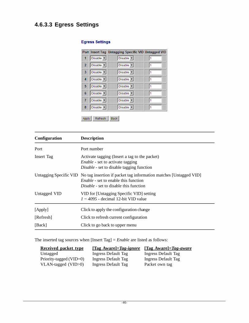
Configuration Description
Port Port number
Insert Tag Activate tagging (Insert a tag to the packet)Enable - set to activate taggingDisable - set to disable tagging function
Untagging Specific VID No tag insertion if packet tag information matches [Untagged VID]Enable - set to enable this functionDisable - set to disable this function
Untagged VID VID for [Untagging Specific VID] setting1 ~ 4095 - decimal 12-bit VID value
[Apply] Click to apply the configuration change
[Refresh] Click to refresh current configuration
[Back] Click to go back to upper menu
The inserted tag sources when [Insert Tag] = Enable are listed as follows:
Received packet type [Tag Aware]=Tag-ignore [Tag Aware]=Tag-awareUntagged Ingress Default Tag Ingress Default TagPriority-tagged (VID=0) Ingress Default Tag Ingress Default TagVLAN-tagged (VID>0) Ingress Default Tag Packet own tag
-47-
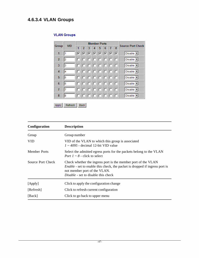
4.6.3.4 VLAN Groups
Configuration Description
Group Group number
VID VID of the VLAN to which this group is associated1 ~ 4095 - decimal 12-bit VID value
Member Ports Select the admitted egress ports for the packets belong to the VLANPort 1 ~ 8 - click to select
Source Port Check Check whether the ingress port is the member port of the VLANEnable - set to enable this check, the packet is dropped if ingress port isnot member port of the VLAN.Disable - set to disable this check
[Apply] Click to apply the configuration change
[Refresh] Click to refresh current configuration
[Back] Click to go back to upper menu
-48-
4.6.4 Important Notes for VLAN ConfigurationSome considerations should be checked in configuring VLAN settings:
1. Switch VLAN Mode selectionIt is suggested to evaluate your VLAN application first and plan your VLAN configurationcarefully before applying it. Any incorrect setting might cause network problem.
2. Aggregation/Trunking configurationMake sure the members of a link aggregation (trunk) group are configured with same VLANconfiguration and are in same VLAN group.
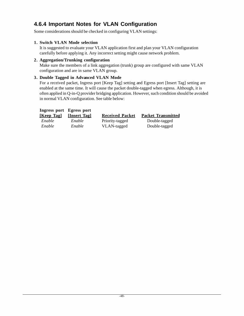
3. Double Tagged in Advanced VLAN ModeFor a received packet, Ingress port [Keep Tag] setting and Egress port [Insert Tag] setting areenabled at the same time. It will cause the packet double-tagged when egress. Although, it isoften applied in Q-in-Q provider bridging application. However, such condition should be avoidedin normal VLAN configuration. See table below:
Ingress port Egress port[Keep Tag] [Insert Tag] Received Packet Packet Transmitted Enable Enable Priority-tagged Double-tagged Enable Enable VLAN-tagged Double-tagged
-49-
4.7 Aggregation
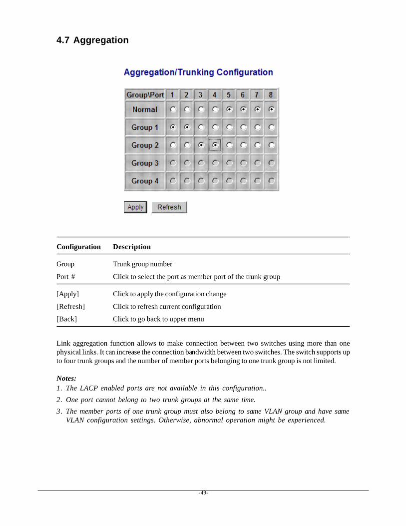
Configuration Description
Group Trunk group number
Port # Click to select the port as member port of the trunk group
[Apply] Click to apply the configuration change
[Refresh] Click to refresh current configuration
[Back] Click to go back to upper menu
Link aggregation function allows to make connection between two switches using more than onephysical links. It can increase the connection bandwidth between two switches. The switch supports upto four trunk groups and the number of member ports belonging to one trunk group is not limited.
Notes:1. The LACP enabled ports are not available in this configuration..2. One port cannot belong to two trunk groups at the same time.3. The member ports of one trunk group must also belong to same VLAN group and have same
VLAN configuration settings. Otherwise, abnormal operation might be experienced.
-50-
4.8 LACP
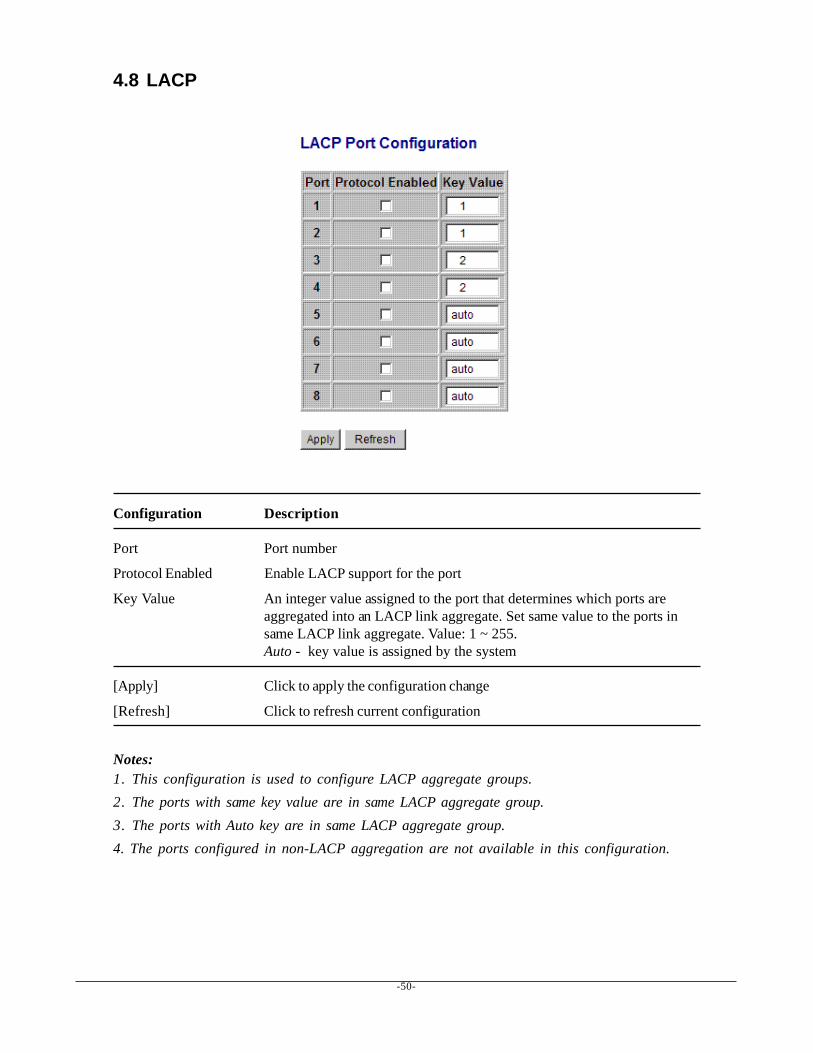
Configuration Description
Port Port number
Protocol Enabled Enable LACP support for the port
Key Value An integer value assigned to the port that determines which ports areaggregated into an LACP link aggregate. Set same value to the ports insame LACP link aggregate. Value: 1 ~ 255.Auto - key value is assigned by the system
[Apply] Click to apply the configuration change
[Refresh] Click to refresh current configuration
Notes:1. This configuration is used to configure LACP aggregate groups.2. The ports with same key value are in same LACP aggregate group.3. The ports with Auto key are in same LACP aggregate group.4. The ports configured in non-LACP aggregation are not available in this configuration.
-51-
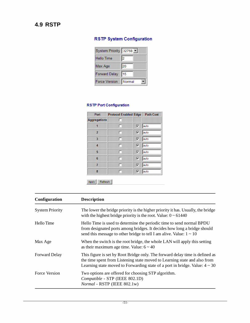
4.9 RSTP
Configuration Description
System Priority The lower the bridge priority is the higher priority it has. Usually, the bridgewith the highest bridge priority is the root. Value: 0 ~ 61440
Hello Time Hello Time is used to determine the periodic time to send normal BPDUfrom designated ports among bridges. It decides how long a bridge shouldsend this message to other bridge to tell I am alive. Value: 1 ~ 10
Max Age When the switch is the root bridge, the whole LAN will apply this settingas their maximum age time. Value: 6 ~ 40
Forward Delay This figure is set by Root Bridge only. The forward delay time is defined asthe time spent from Listening state moved to Learning state and also fromLearning state moved to Forwarding state of a port in bridge. Value: 4 ~ 30
Force Version Two options are offered for choosing STP algorithm.Compatible - STP (IEEE 802.1D)Normal - RSTP (IEEE 802.1w)
-52-
Aggregations Enabled to support port trunking in STP. It means a link aggregate istreated as a physical port in RSTP/STP operation.
Port Protocol Enabled Port is enabled to support RSTP/STP.
Port Edge An Edge Port is a port connected to a device that knows nothing aboutSTP or RSTP. Usually, the connected device is an end station. Edge Portswill immediately transit to forwarding state and skip the listening andlearning state because the edge ports cannot create bridging loops in thenetwork.
Port Path Cost Specifies the path cost of the port that switch uses to determine which portare the forwarding ports the lowest number is forwarding ports, the rage is1 ~ 200,000,000 and Auto. Auto means a default cost is automaticallycalculated in RSTP operation based on the port link speed.The default costs are :Link Speed Auto Default Cost10Mbps 2000000100Mbps 2000001000Mbps 20000
[Apply] Click to apply the configuration change
[Refresh] Click to refresh current configuration
4.10 802.1X Configuration
-53-
Configuration Description
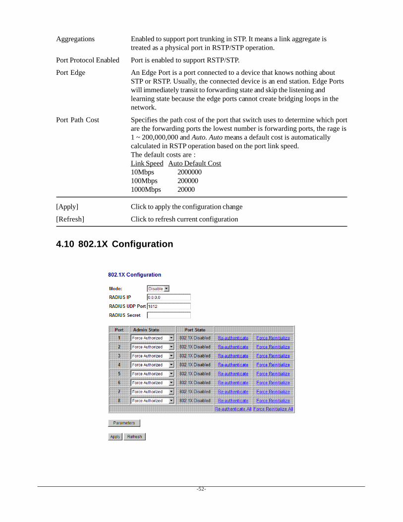
Mode Disabled - disable 802.1X functionEnabled - enable 802.1X function
RADIUS IP IP address of the Radius server
RADIUS UDP Port The UDP port for authentication requests to the specified Radius server
RADIUS Secret The encryption key for use during authentication sessions with the Radiusserver. It must match the key used on the Radius server.
Port Port number
Admin State Port 802.1X controlAuto - set to the Authorized or Unauthorized state in accordance with theoutcome of an authentication exchange between the Supplicant and theAuthentication Server.Force Authorized - the port is forced to be in authorized state.Force Unauthorized - the port is forced to be in unauthorized state.
Port State Port 802.1X state802.1X Disabled - the port is in 802.1X disabled stateLink Down - the port is in link down stateAuthorized (green color) - the port is in 802.1X authorized stateUnauthorized (red color) - the port is in 802.1X unauthorized state
[Re-authenticate] Click to perform a manual authentication for the port
[Force Reinitialize] Click to perform an 802.1X initialization for the port
[Re-authenticate All] Click to perform manual authentication for all ports
[Force Reinitialize All] Click to perform 802.1X initialization for all ports
[Parameters] Click to configure Re-authentication parameters
[Apply] Click to apply the configuration change
[Refresh] Click to refresh current configuration
-54-
4.10.1 802.1X Re-authentication Parameters
Configuration Description
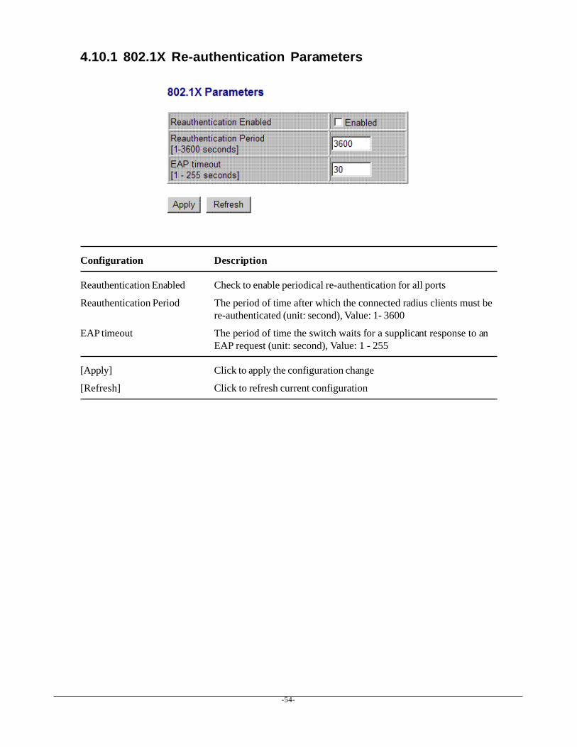
Reauthentication Enabled Check to enable periodical re-authentication for all ports
Reauthentication Period The period of time after which the connected radius clients must bere-authenticated (unit: second), Value: 1- 3600
EAP timeout The period of time the switch waits for a supplicant response to anEAP request (unit: second), Value: 1 - 255
[Apply] Click to apply the configuration change
[Refresh] Click to refresh current configuration
-55-
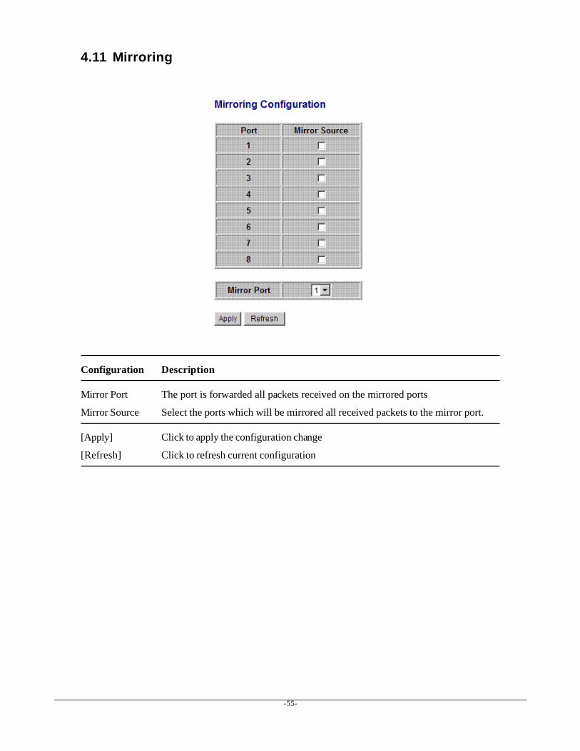
4.11 Mirroring
Configuration Description
Mirror Port The port is forwarded all packets received on the mirrored ports
Mirror Source Select the ports which will be mirrored all received packets to the mirror port.
[Apply] Click to apply the configuration change
[Refresh] Click to refresh current configuration
-56-
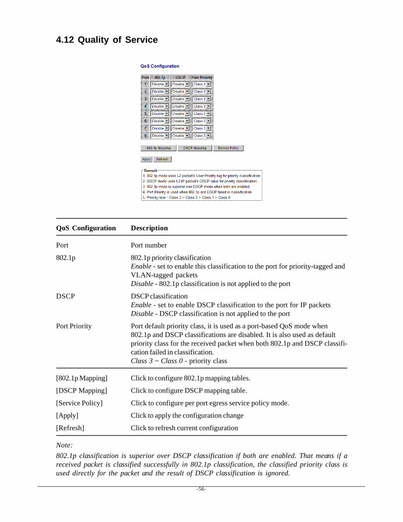
4.12 Quality of Service
QoS Configuration Description
Port Port number
802.1p 802.1p priority classificationEnable - set to enable this classification to the port for priority-tagged andVLAN-tagged packetsDisable - 802.1p classification is not applied to the port
DSCP DSCP classificationEnable - set to enable DSCP classification to the port for IP packetsDisable - DSCP classification is not applied to the port
Port Priority Port default priority class, it is used as a port-based QoS mode when802.1p and DSCP classifications are disabled. It is also used as defaultpriority class for the received packet when both 802.1p and DSCP classifi-cation failed in classification.Class 3 ~ Class 0 - priority class
[802.1p Mapping] Click to configure 802.1p mapping tables.
[DSCP Mapping] Click to configure DSCP mapping table.
[Service Policy] Click to configure per port egress service policy mode.
[Apply] Click to apply the configuration change
[Refresh] Click to refresh current configuration
Note:802.1p classification is superior over DSCP classification if both are enabled. That means if areceived packet is classified successfully in 802.1p classification, the classified priority class isused directly for the packet and the result of DSCP classification is ignored.
-57-
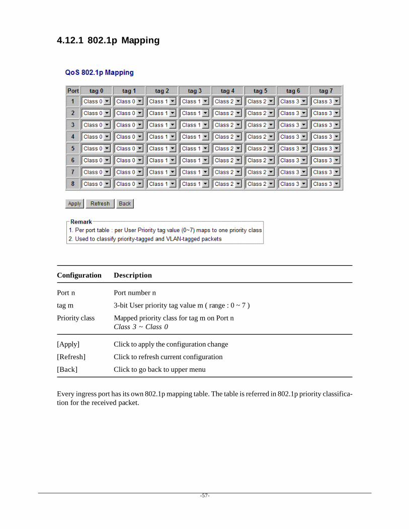
4.12.1 802.1p Mapping
Configuration Description
Port n Port number n
tag m 3-bit User priority tag value m ( range : 0 ~ 7 )
Priority class Mapped priority class for tag m on Port nClass 3 ~ Class 0
[Apply] Click to apply the configuration change
[Refresh] Click to refresh current configuration
[Back] Click to go back to upper menu
Every ingress port has its own 802.1p mapping table. The table is referred in 802.1p priority classifica-tion for the received packet.
-58-
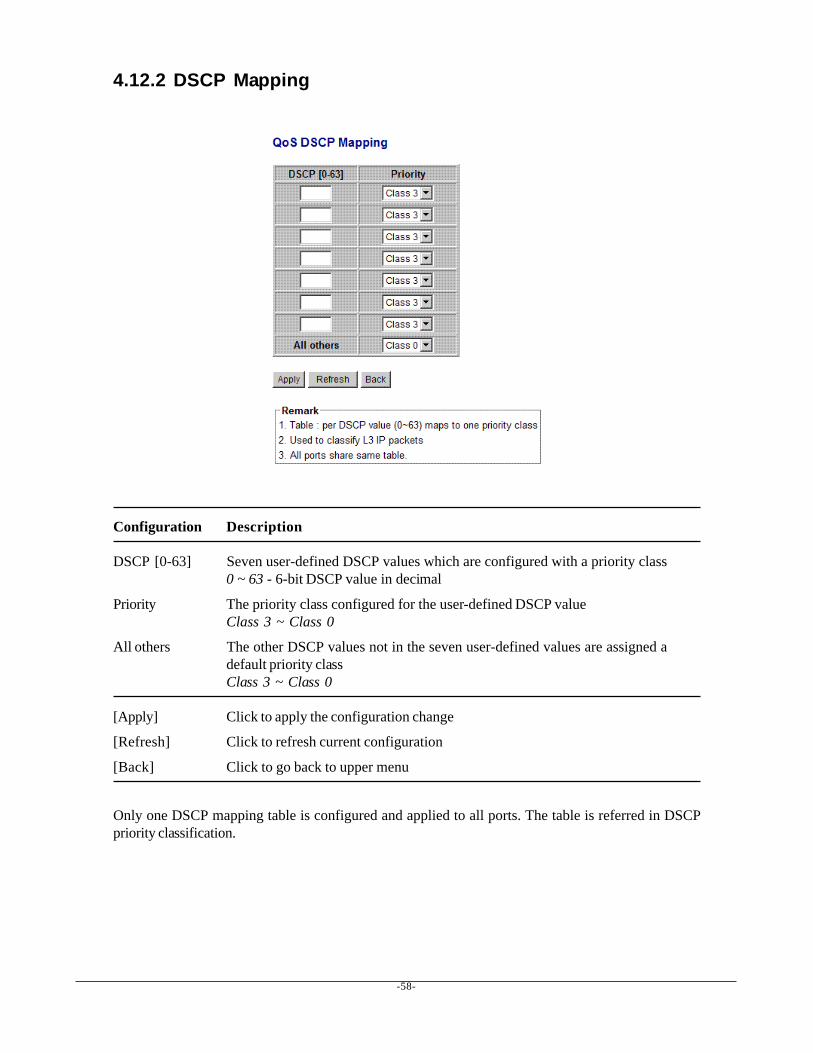
4.12.2 DSCP Mapping
Configuration Description
DSCP [0-63] Seven user-defined DSCP values which are configured with a priority class0 ~ 63 - 6-bit DSCP value in decimal
Priority The priority class configured for the user-defined DSCP valueClass 3 ~ Class 0
All others The other DSCP values not in the seven user-defined values are assigned adefault priority classClass 3 ~ Class 0
[Apply] Click to apply the configuration change
[Refresh] Click to refresh current configuration
[Back] Click to go back to upper menu
Only one DSCP mapping table is configured and applied to all ports. The table is referred in DSCPpriority classification.
-59-
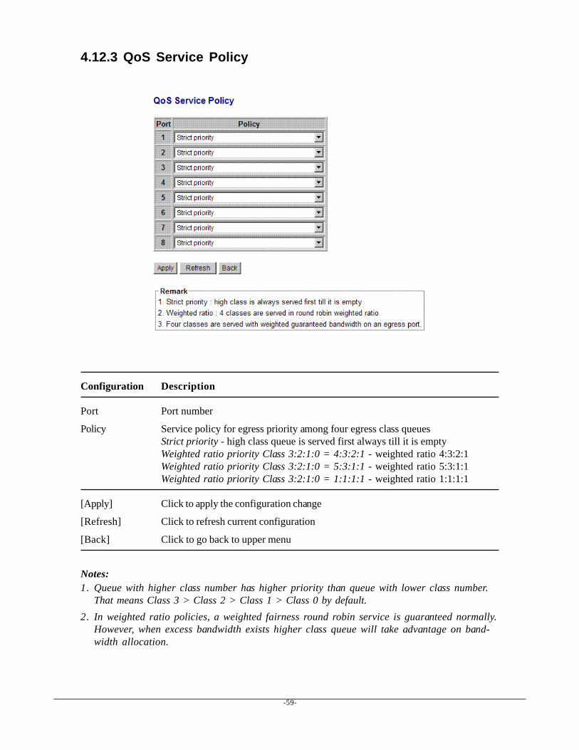
4.12.3 QoS Service Policy
Configuration Description
Port Port number
Policy Service policy for egress priority among four egress class queuesStrict priority - high class queue is served first always till it is emptyWeighted ratio priority Class 3:2:1:0 = 4:3:2:1 - weighted ratio 4:3:2:1Weighted ratio priority Class 3:2:1:0 = 5:3:1:1 - weighted ratio 5:3:1:1Weighted ratio priority Class 3:2:1:0 = 1:1:1:1 - weighted ratio 1:1:1:1
[Apply] Click to apply the configuration change
[Refresh] Click to refresh current configuration
[Back] Click to go back to upper menu
Notes:1. Queue with higher class number has higher priority than queue with lower class number.
That means Class 3 > Class 2 > Class 1 > Class 0 by default.2. In weighted ratio policies, a weighted fairness round robin service is guaranteed normally.
However, when excess bandwidth exists higher class queue will take advantage on band-width allocation.
-60-
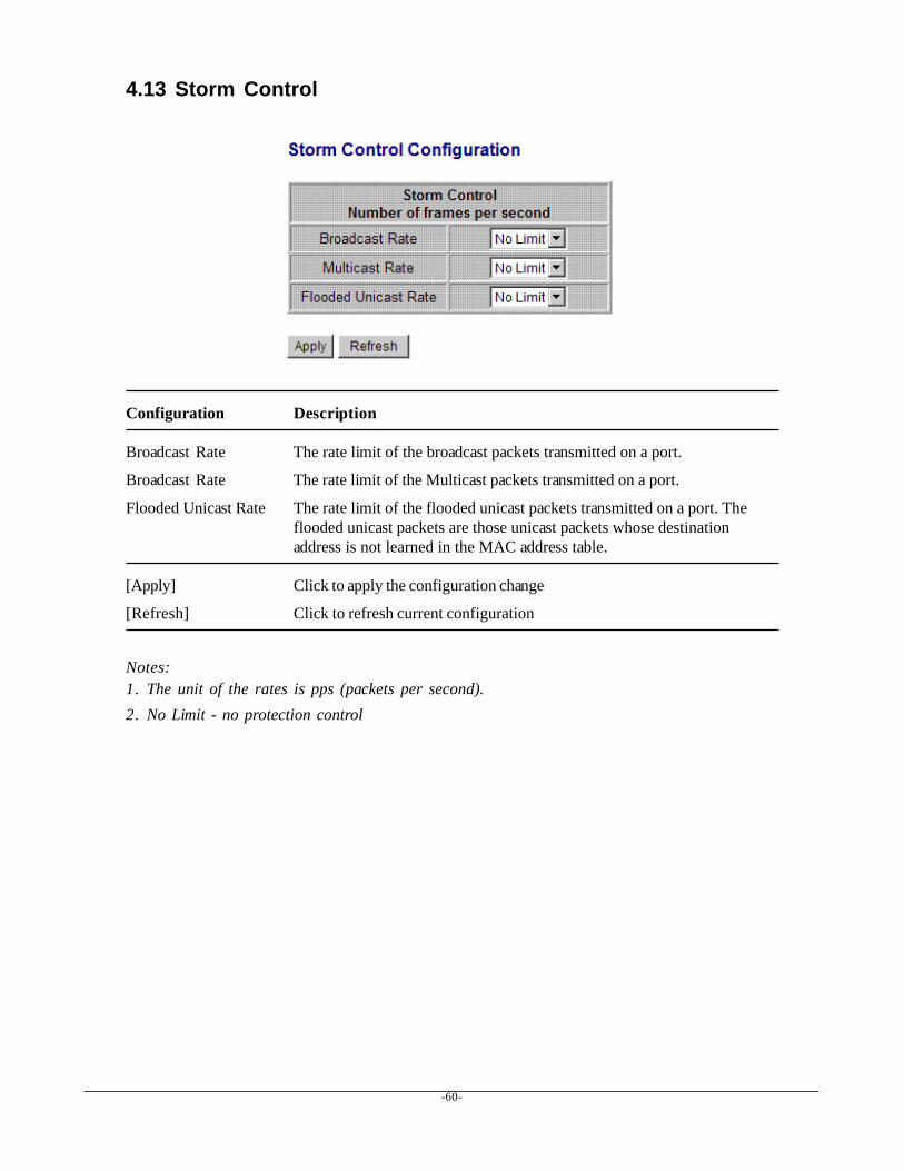
4.13 Storm Control
Configuration Description
Broadcast Rate The rate limit of the broadcast packets transmitted on a port.
Broadcast Rate The rate limit of the Multicast packets transmitted on a port.
Flooded Unicast Rate The rate limit of the flooded unicast packets transmitted on a port. Theflooded unicast packets are those unicast packets whose destinationaddress is not learned in the MAC address table.
[Apply] Click to apply the configuration change
[Refresh] Click to refresh current configuration
Notes:1. The unit of the rates is pps (packets per second).2. No Limit - no protection control
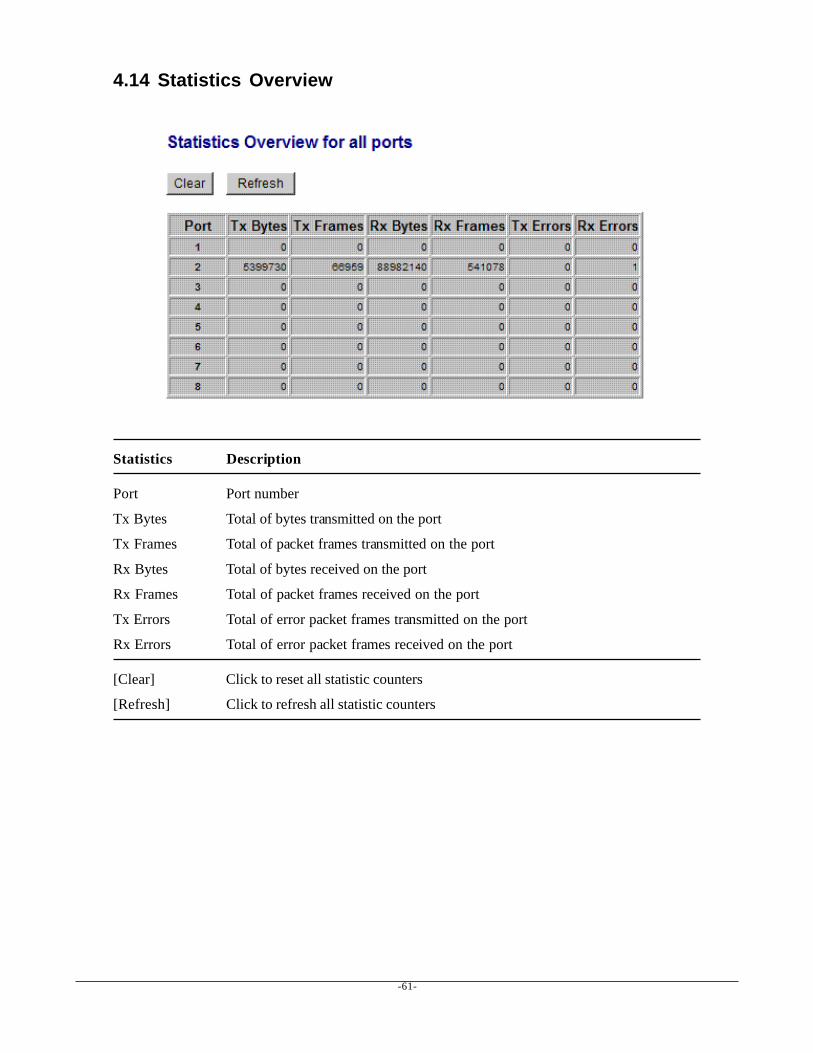
-61-
4.14 Statistics Overview
Statistics Description
Port Port number
Tx Bytes Total of bytes transmitted on the port
Tx Frames Total of packet frames transmitted on the port
Rx Bytes Total of bytes received on the port
Rx Frames Total of packet frames received on the port
Tx Errors Total of error packet frames transmitted on the port
Rx Errors Total of error packet frames received on the port
[Clear] Click to reset all statistic counters
[Refresh] Click to refresh all statistic counters
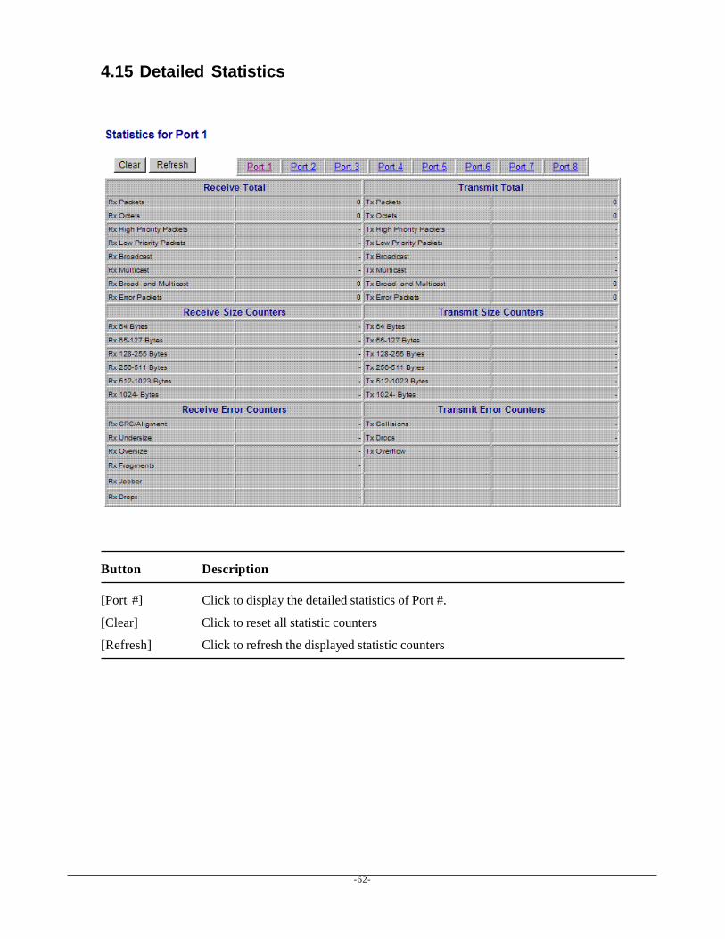
-62-
4.15 Detailed Statistics
Button Description
[Port #] Click to display the detailed statistics of Port #.
[Clear] Click to reset all statistic counters
[Refresh] Click to refresh the displayed statistic counters

-63-
4.16 LACP Status
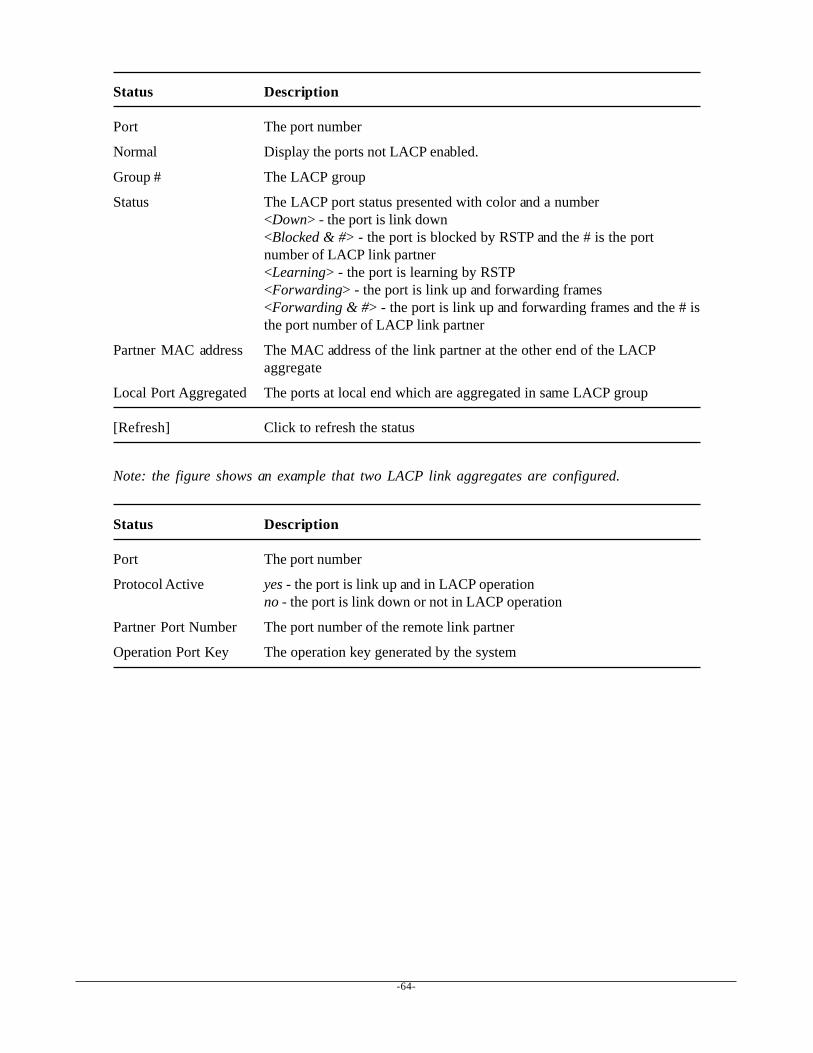
-64-
Status Description
Port The port number
Normal Display the ports not LACP enabled.
Group # The LACP group
Status The LACP port status presented with color and a number<Down> - the port is link down<Blocked & #> - the port is blocked by RSTP and the # is the portnumber of LACP link partner<Learning> - the port is learning by RSTP<Forwarding> - the port is link up and forwarding frames<Forwarding & #> - the port is link up and forwarding frames and the # isthe port number of LACP link partner
Partner MAC address The MAC address of the link partner at the other end of the LACPaggregate
Local Port Aggregated The ports at local end which are aggregated in same LACP group
[Refresh] Click to refresh the status
Note: the figure shows an example that two LACP link aggregates are configured.
Status Description
Port The port number
Protocol Active yes - the port is link up and in LACP operationno - the port is link down or not in LACP operation
Partner Port Number The port number of the remote link partner
Operation Port Key The operation key generated by the system
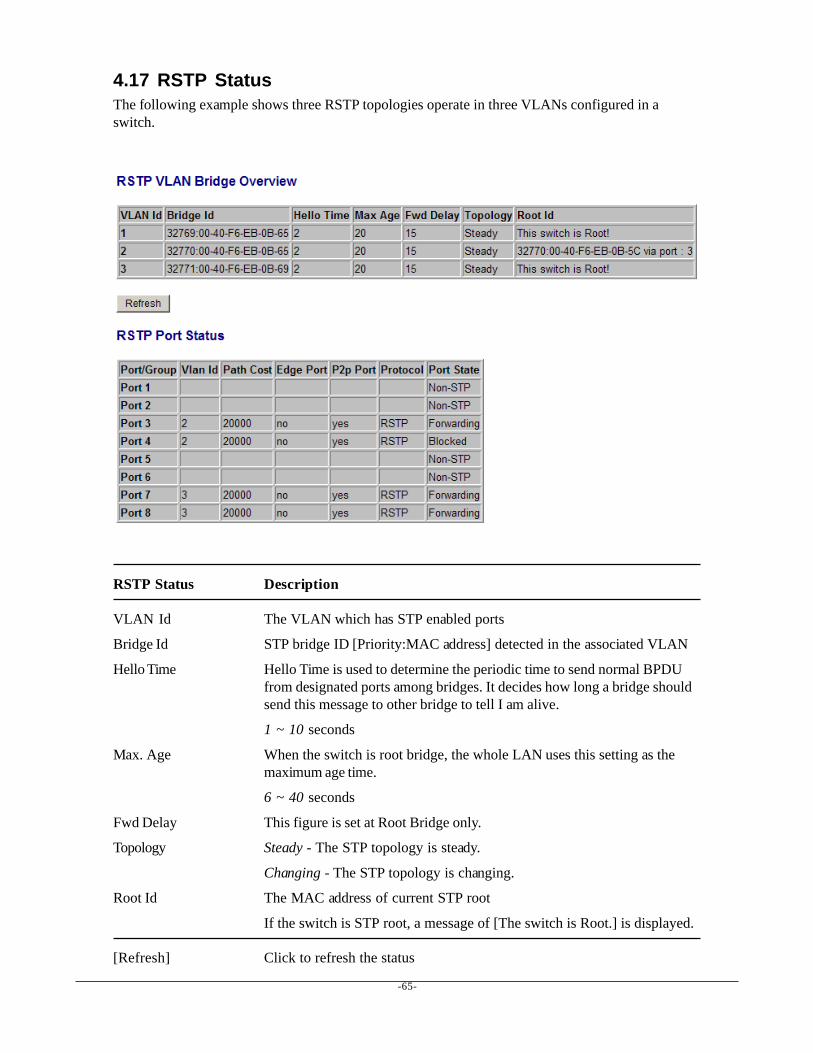
-65-
4.17 RSTP StatusThe following example shows three RSTP topologies operate in three VLANs configured in aswitch.
RSTP Status Description
VLAN Id The VLAN which has STP enabled ports
Bridge Id STP bridge ID [Priority:MAC address] detected in the associated VLAN
Hello Time Hello Time is used to determine the periodic time to send normal BPDUfrom designated ports among bridges. It decides how long a bridge shouldsend this message to other bridge to tell I am alive.
1 ~ 10 seconds
Max. Age When the switch is root bridge, the whole LAN uses this setting as themaximum age time.
6 ~ 40 seconds
Fwd Delay This figure is set at Root Bridge only.
Topology Steady - The STP topology is steady.
Changing - The STP topology is changing.
Root Id The MAC address of current STP root
If the switch is STP root, a message of [The switch is Root.] is displayed.
[Refresh] Click to refresh the status
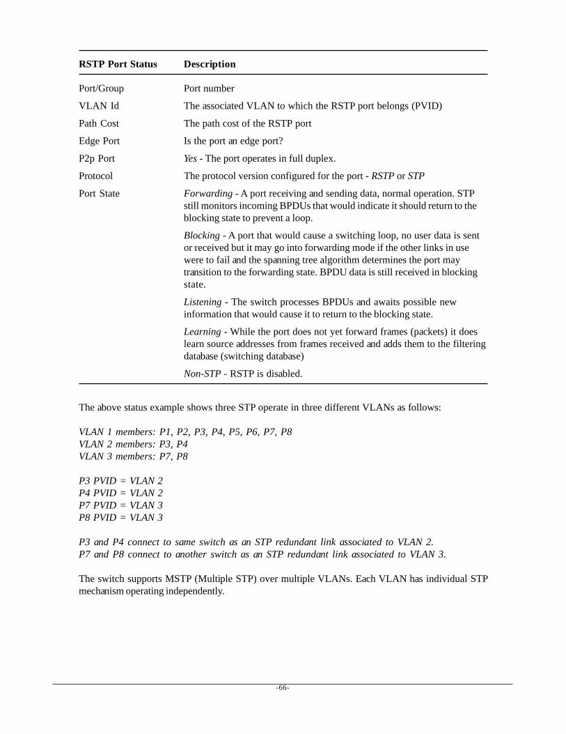
-66-
RSTP Port Status Description
Port/Group Port number
VLAN Id The associated VLAN to which the RSTP port belongs (PVID)
Path Cost The path cost of the RSTP port
Edge Port Is the port an edge port?
P2p Port Yes - The port operates in full duplex.
Protocol The protocol version configured for the port - RSTP or STP
Port State Forwarding - A port receiving and sending data, normal operation. STPstill monitors incoming BPDUs that would indicate it should return to theblocking state to prevent a loop.
Blocking - A port that would cause a switching loop, no user data is sentor received but it may go into forwarding mode if the other links in usewere to fail and the spanning tree algorithm determines the port maytransition to the forwarding state. BPDU data is still received in blockingstate.
Listening - The switch processes BPDUs and awaits possible newinformation that would cause it to return to the blocking state.
Learning - While the port does not yet forward frames (packets) it doeslearn source addresses from frames received and adds them to the filteringdatabase (switching database)
Non-STP - RSTP is disabled.
The above status example shows three STP operate in three different VLANs as follows:
VLAN 1 members: P1, P2, P3, P4, P5, P6, P7, P8VLAN 2 members: P3, P4VLAN 3 members: P7, P8
P3 PVID = VLAN 2P4 PVID = VLAN 2P7 PVID = VLAN 3P8 PVID = VLAN 3
P3 and P4 connect to same switch as an STP redundant link associated to VLAN 2.P7 and P8 connect to another switch as an STP redundant link associated to VLAN 3.
The switch supports MSTP (Multiple STP) over multiple VLANs. Each VLAN has individual STPmechanism operating independently.
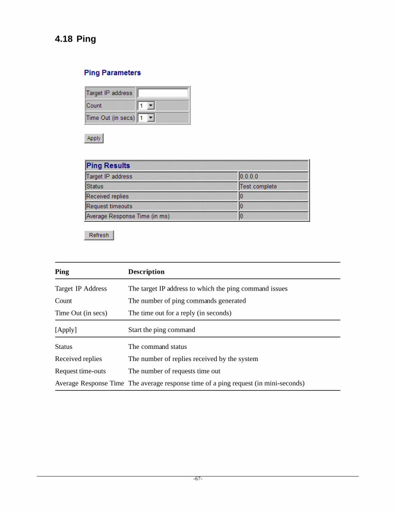
-67-
4.18 Ping
Ping Description
Target IP Address The target IP address to which the ping command issues
Count The number of ping commands generated
Time Out (in secs) The time out for a reply (in seconds)
[Apply] Start the ping command
Status The command status
Received replies The number of replies received by the system
Request time-outs The number of requests time out
Average Response Time The average response time of a ping request (in mini-seconds)
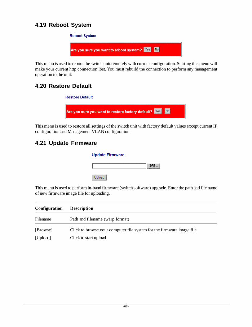
-68-
4.19 Reboot System
This menu is used to reboot the switch unit remotely with current configuration. Starting this menu willmake your current http connection lost. You must rebuild the connection to perform any managementoperation to the unit.
4.20 Restore Default
This menu is used to restore all settings of the switch unit with factory default values except current IPconfiguration and Management VLAN configuration.
4.21 Update Firmware
This menu is used to perform in-band firmware (switch software) upgrade. Enter the path and file nameof new firmware image file for uploading.
Configuration Description
Filename Path and filename (warp format)
[Browse] Click to browse your computer file system for the firmware image file
[Upload] Click to start upload
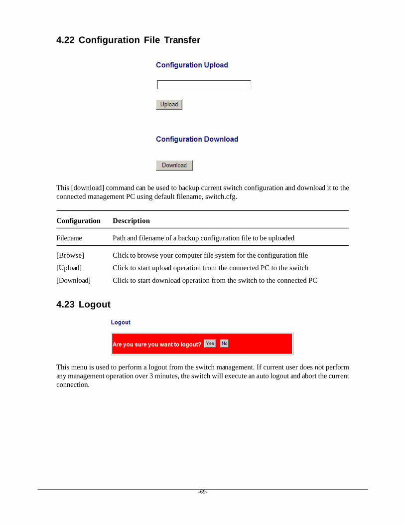
-69-
4.22 Configuration File Transfer
This [download] command can be used to backup current switch configuration and download it to theconnected management PC using default filename, switch.cfg.
Configuration Description
Filename Path and filename of a backup configuration file to be uploaded
[Browse] Click to browse your computer file system for the configuration file
[Upload] Click to start upload operation from the connected PC to the switch
[Download] Click to start download operation from the switch to the connected PC
4.23 Logout
This menu is used to perform a logout from the switch management. If current user does not performany management operation over 3 minutes, the switch will execute an auto logout and abort the currentconnection.
-70-
5. SNMP SupportSNMP version support Snmp v1, v2c management
Managed Objects MIB-IIsystem OBJECT IDENTIFIER ::= { mib-2 1 }interfaces OBJECT IDENTIFIER ::= { mib-2 2 }ip OBJECT IDENTIFIER ::= { mib-2 4 }snmp OBJECT IDENTIFIER ::= { mib-2 11 }dot1dBridge OBJECT IDENTIFIER ::= { mib-2 17 }ifMIB OBJECT IDENTIFIER ::= { mib-2 31 }
RFC RFC 3418 - Management Information Base (MIB) for the SimpleNetwork Management Protocol (SNMP)
RFC 1907 - Management Information Base for Version 2 of theSimple Network Management Protocol (SNMPv2)
RFC 1213 - Management Information Base for Network Manage-ment of TCP/IP-based internets:MIB-II
RFC 1158 - Management Information Base for network manage-ment of TCP/IP-based internets: MIB-II
RFC 1493 - Definitions of Managed Objects for Bridges
RFC 2863 - The Interfaces Group MIB
RFC 1573 - Evolution of the Interfaces Group of MIB-II
SNMP Trap Support TRAP_COLDSTART - the device boot up trap
TRAP_LINKUP - the port link recovery trap
TRAP_LINKDOWN - port link down trap
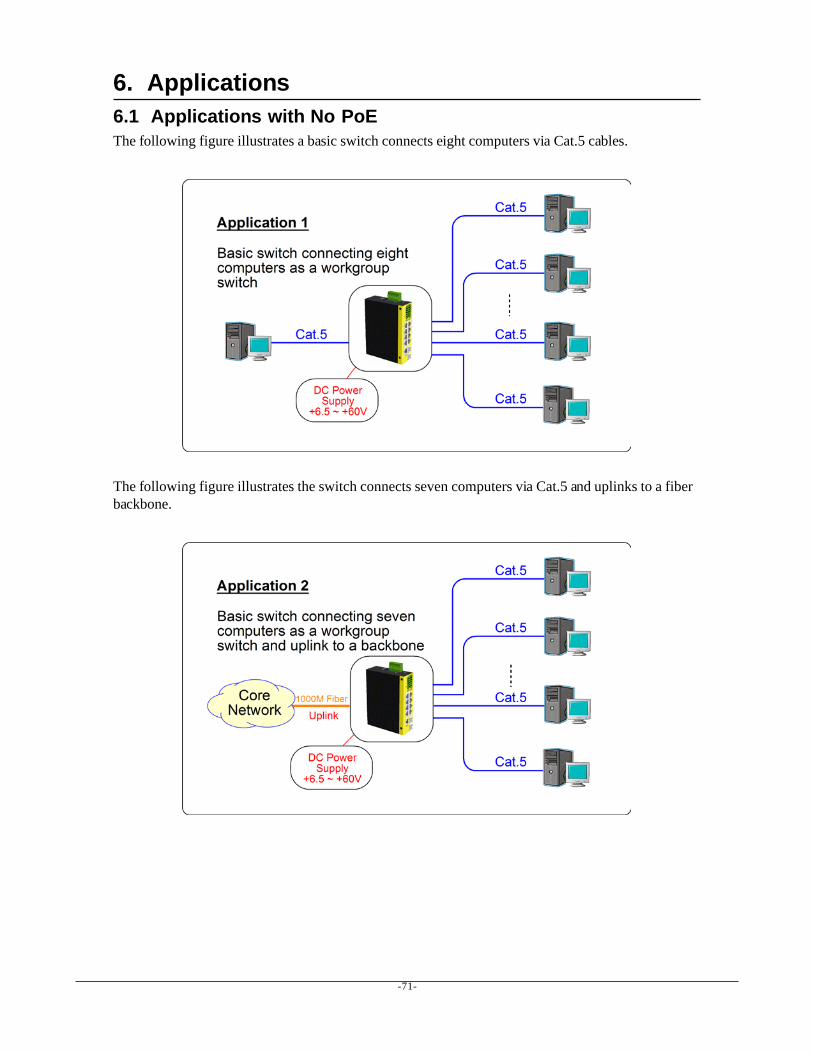
-71-
6. Applications6.1 Applications with No PoEThe following figure illustrates a basic switch connects eight computers via Cat.5 cables.
The following figure illustrates the switch connects seven computers via Cat.5 and uplinks to a fiberbackbone.
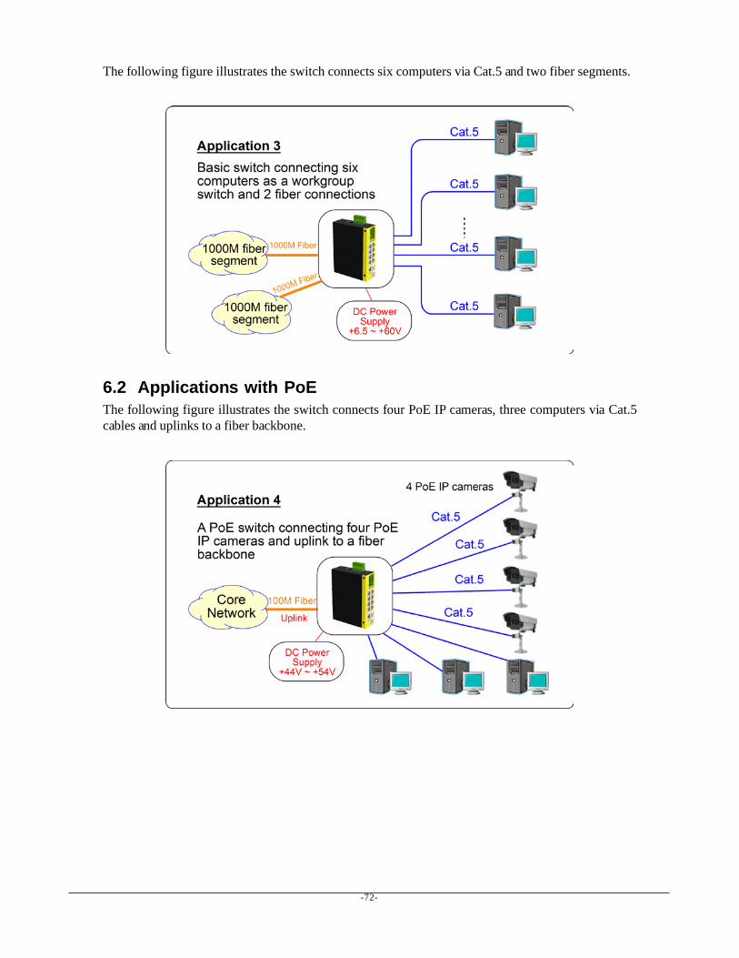
-72-
The following figure illustrates the switch connects six computers via Cat.5 and two fiber segments.
6.2 Applications with PoEThe following figure illustrates the switch connects four PoE IP cameras, three computers via Cat.5cables and uplinks to a fiber backbone.
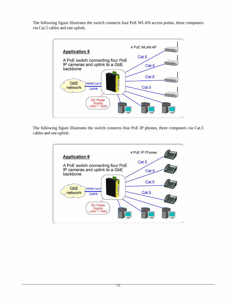
-73-
The following figure illustrates the switch connects four PoE WLAN access points, three computersvia Cat.5 cables and one uplink.
The following figure illustrates the switch connects four PoE IP phones, three computers via Cat.5cables and one uplink.
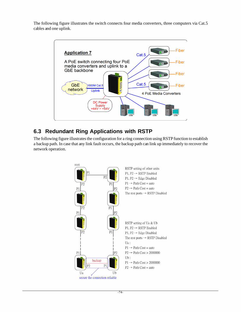
-74-
The following figure illustrates the switch connects four media converters, three computers via Cat.5cables and one uplink.
6.3 Redundant Ring Applications with RSTPThe following figure illustrates the configuration for a ring connection using RSTP function to establisha backup path. In case that any link fault occurs, the backup path can link up immediately to recover thenetwork operation.
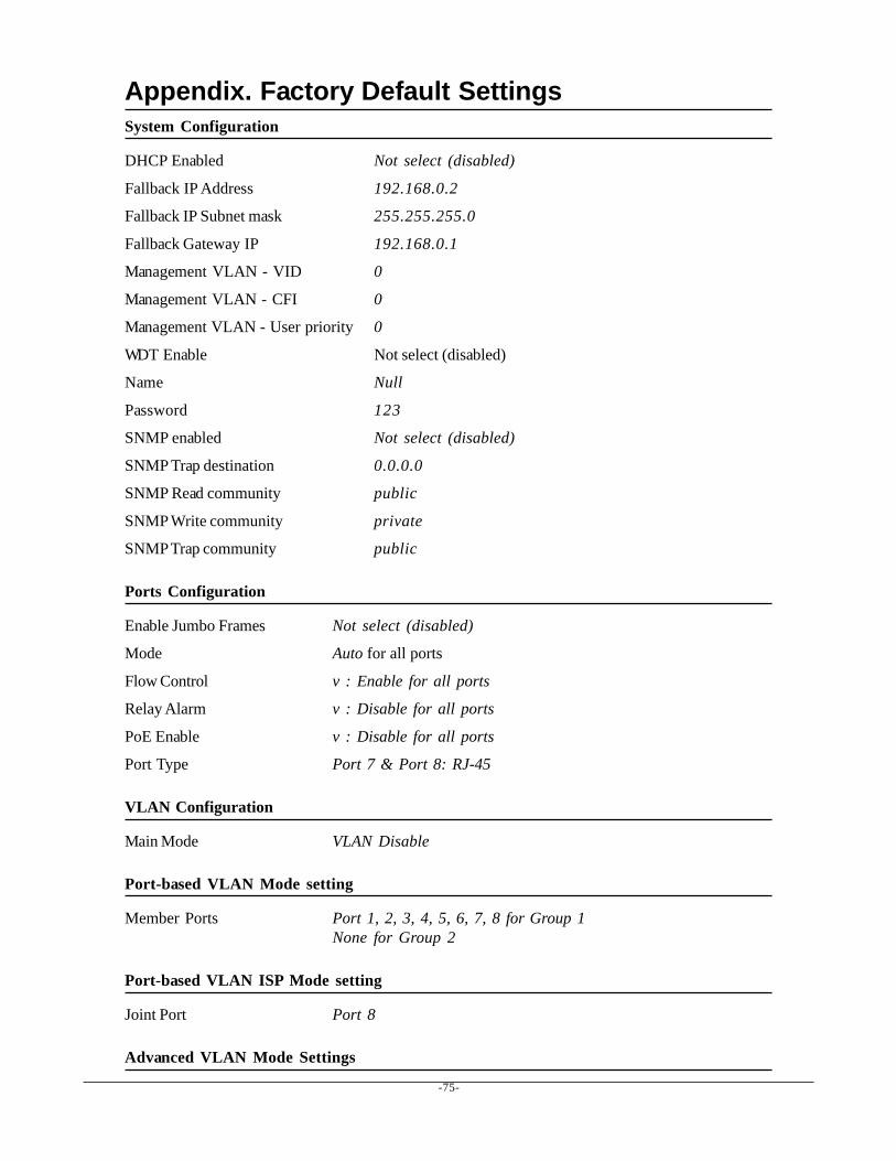
-75-
Appendix. Factory Default SettingsSystem Configuration
DHCP Enabled Not select (disabled)
Fallback IP Address 192.168.0.2
Fallback IP Subnet mask 255.255.255.0
Fallback Gateway IP 192.168.0.1
Management VLAN - VID 0
Management VLAN - CFI 0
Management VLAN - User priority 0
WDT Enable Not select (disabled)
Name Null
Password 123
SNMP enabled Not select (disabled)
SNMP Trap destination 0.0.0.0
SNMP Read community public
SNMP Write community private
SNMP Trap community public
Ports Configuration
Enable Jumbo Frames Not select (disabled)
Mode Auto for all ports
Flow Control v : Enable for all ports
Relay Alarm v : Disable for all ports
PoE Enable v : Disable for all ports
Port Type Port 7 & Port 8: RJ-45
VLAN Configuration
Main Mode VLAN Disable
Port-based VLAN Mode setting
Member Ports Port 1, 2, 3, 4, 5, 6, 7, 8 for Group 1None for Group 2
Port-based VLAN ISP Mode setting
Joint Port Port 8
Advanced VLAN Mode Settings
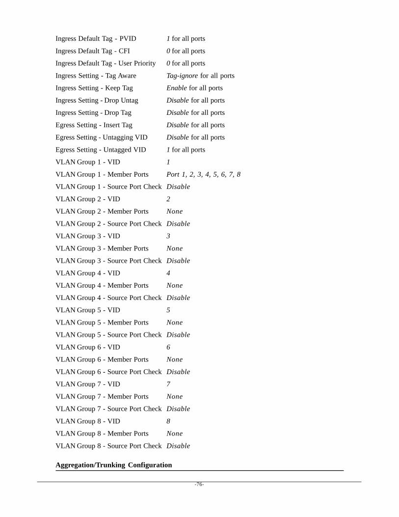
-76-
Ingress Default Tag - PVID 1 for all ports
Ingress Default Tag - CFI 0 for all ports
Ingress Default Tag - User Priority 0 for all ports
Ingress Setting - Tag Aware Tag-ignore for all ports
Ingress Setting - Keep Tag Enable for all ports
Ingress Setting - Drop Untag Disable for all ports
Ingress Setting - Drop Tag Disable for all ports
Egress Setting - Insert Tag Disable for all ports
Egress Setting - Untagging VID Disable for all ports
Egress Setting - Untagged VID 1 for all ports
VLAN Group 1 - VID 1
VLAN Group 1 - Member Ports Port 1, 2, 3, 4, 5, 6, 7, 8
VLAN Group 1 - Source Port Check Disable
VLAN Group 2 - VID 2
VLAN Group 2 - Member Ports None
VLAN Group 2 - Source Port Check Disable
VLAN Group 3 - VID 3
VLAN Group 3 - Member Ports None
VLAN Group 3 - Source Port Check Disable
VLAN Group 4 - VID 4
VLAN Group 4 - Member Ports None
VLAN Group 4 - Source Port Check Disable
VLAN Group 5 - VID 5
VLAN Group 5 - Member Ports None
VLAN Group 5 - Source Port Check Disable
VLAN Group 6 - VID 6
VLAN Group 6 - Member Ports None
VLAN Group 6 - Source Port Check Disable
VLAN Group 7 - VID 7
VLAN Group 7 - Member Ports None
VLAN Group 7 - Source Port Check Disable
VLAN Group 8 - VID 8
VLAN Group 8 - Member Ports None
VLAN Group 8 - Source Port Check Disable
Aggregation/Trunking Configuration

-77-
Group 1 -4 Member Ports None
LACP Port Configuration
Protocol Enabled Not select (disabled) for all ports
Key Value auto for all ports
RSTP System Configuration
System Priority 32768
Hello Time 2
Max Age 20
Forward Delay 15
Force Version Normal
RSTP Port Configuration
Protocol enabled Not select (disabled) for all ports
Edge v: Select for all ports
Max Age 20
Forward Delay 15
Force Version Normal
802.1X Configuration
Mode Disabled
RADIUS IP 0.0.0.0
RADIUS UDP Port 1812
RADIUS Secret None
Admin State Force Authorized for all ports
Reauthentication Enabled No
Reauthentication Period 3600
EAP Timeout 30
Port 1~Port 8 - tag 1 Class 0
Port 1~Port 8 - tag 2 Class 1
Port 1~Port 8 - tag 3 Class 1
Port 1~Port 8 - tag 4 Class 2
Port 1~Port 8 - tag 5 Class 2
Port 1~Port 8 - tag 6 Class 3
Port 1~Port 8 - tag 7 Class 3
Mirroring Configuration

-78-
Mirror source Not select for all ports
Mirror Port 1 (Port 1)
Quality of Service Configuration
802.1p Classification Disable for all ports
DSCP Classification Disable for all ports
Port Priority Class 3 for all ports
QoS 802.1p Mapping
Port 1~Port 8 - tag 0 Class 0
Port 1~Port 8 - tag 1 Class 0
Port 1~Port 8 - tag 2 Class 1
Port 1~Port 8 - tag 3 Class 1
Port 1~Port 8 - tag 4 Class 2
Port 1~Port 8 - tag 5 Class 2
Port 1~Port 8 - tag 6 Class 3
Port 1~Port 8 - tag 7 Class 3
QoS DSCP Mapping
DSCP 1 / Priority 0, Class 0
DSCP 2 / Priority 0, Class 0
DSCP 3 / Priority 0, Class 0
DSCP 4 / Priority 0, Class 0
DSCP 5 / Priority 0, Class 0
DSCP 6 / Priority 0, Class 0
DSCP 7 / Priority 0, Class 0
All others DSCP Class 0
QoS Service Policy
Port 1 Strict priority
Port 2 Strict priority
Port 3 Strict priority
Port 4 Strict priority
Port 5 Strict priority
Port 6 Strict priority
Port 7 Strict priority
Port 8 Strict priority
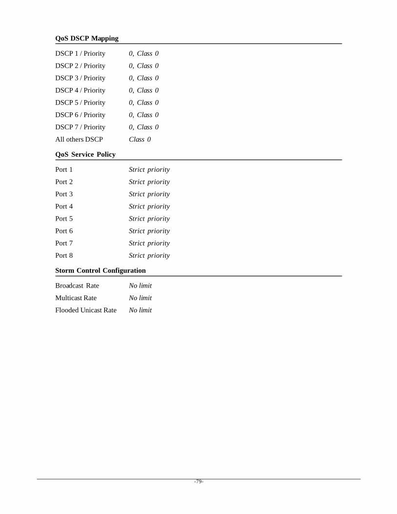
-79-
QoS DSCP Mapping
DSCP 1 / Priority 0, Class 0
DSCP 2 / Priority 0, Class 0
DSCP 3 / Priority 0, Class 0
DSCP 4 / Priority 0, Class 0
DSCP 5 / Priority 0, Class 0
DSCP 6 / Priority 0, Class 0
DSCP 7 / Priority 0, Class 0
All others DSCP Class 0
QoS Service Policy
Port 1 Strict priority
Port 2 Strict priority
Port 3 Strict priority
Port 4 Strict priority
Port 5 Strict priority
Port 6 Strict priority
Port 7 Strict priority
Port 8 Strict priority
Storm Control Configuration
Broadcast Rate No limit
Multicast Rate No limit
Flooded Unicast Rate No limit