Embed Size (px)
Citation preview

Operating and Service Guide
Keysight Truevolt Series Digital Multimeters
Test Equipment Depot - 800.517.8431 - 99 Washington Street Melrose, MA 02176 - TestEquipmentDepot.com
Safety and Regulatory Information 11
Notices 11Manual Information 11Software Revision 11Warranty 11Technology Licenses 11Restricted Rights Legend 12
Safety Notices 13Safety Symbols 13Safety Information 14
General 14Measurement Limits 16Input Terminal Measurement Limits 18Sense Terminal Measurement Limits 18IEC Measurement Category II 19
Keysight 34138A Test Lead Set 19Test Lead Ratings 19Operation 19Maintenance 19Declaration of Conformity 20
Welcome 21
Introductory Information 21User Information 21SCPI Programming Reference 22Service and Repair 22Performance Verification 22Calibration Procedures 22
Introduction to the Instrument 23
Instrument at a Glance 23Display – Easily display, save and document your measurement results 23Measurements – Keysight’s Truevolt measurement performance with modern I/O accessibility 23Programming Language 23
Front Panel at a Glance 24Front Panel Keys 24
Rear Panel at a Glance 25Models and Options 26
Options Installed at Factory 26Options Installed by Distributor or End Customer 26
Remote Interface Configuration 27Connectivity Software 27GPIB Configuration 27LAN Configuration 28Web Interface 31
LAN Configuration Procedure 32More about IP Addresses and Dot Notation 33
Firmware Update 34Contacting Keysight Technologies 35
Quick Start 36
Prepare Instrument for Use 36Setting the AC Mains Line Voltage Selector and Fuse Installation 37
Connect Power and I/O Cables 39
4 Keysight Truevolt Series Operating and Service Guide
Adjust the Carrying Handle 40Use Built-in Help System 41
View the help information for a front panel key 41View the list of help topics and use interactive demos 42View the list of recent instrument errors. 43View the help information for displayed messages. 43
Rack Mount the Instrument 44Removing the Handle and Bumpers 44Rack Mounting a Single Instrument 44Rack Mounting Instruments Side-by-Side 44Sliding Support Shelf 45
Features and Functions 46
Continuous, Data Log, and Digitize Modes 47Continuous Mode 47Data Log Mode 47Digitize Mode 47Data Log and Digitize Mode Default Settings 48Additional Data Log Default Settings 48Additional Digitize Default Settings 49
Front Panel Menu Reference 50[Acquire] key 54[Math] key 54[Display] key 54[Utility] key 55
Measurements 56DC Voltage 57AC Voltage 60DC Current 62AC Current 64Resistance 66Temperature (34460A and 34461A) 69Temperature (34465A and 34470A) 71Capacitance 76Continuity 77Diode 78Frequency and Period 79Data Logging 81Digitizing 86Level Triggering 91Secondary Measurements 93
Triggering and Readings 95Instrument trigger model 95Trigger delay and multiple samples 97Storing and clearing readings 98
Probe Hold 100Math - Introduction 101
Math - Null 102Math - dB/dBm Scaling 103Math - Scaling 105Math - Smoothing 108Math - Statistics 109Math - Limits 110
Keysight Truevolt Series Operating and Service Guide 5
Display - Introduction 114Selecting the Display 114Number 116Bar Meter 121Trend Chart (Continuous Measurement Mode) 124Trend Chart (Digitize and Data Log Modes) 127Histogram 133
Utility Menu - Introduction 138Utility - Autocalibration (34465A/70A only) 139Utility - Store and Recall State and Preference Files 140Utility Menu - Manage Files 142Utility Menu - I/O Configuration 144Utility Menu - Test/Admin 147Utility Menu - System Setup 149
Web Interface 152Welcome Page 152Instrument Monitor and Control Page 153Configuration Page 157Help 158
Measurement Tutorial 159
Measurement Considerations 160Metrology 161DC Measurement Considerations 162
Thermal EMF Errors 162Loading Errors (DC Voltage) 162
Noise Rejection 163Rejecting Power–Line Noise Voltages 163Common Mode Rejection (CMR) 163Noise Caused by Magnetic Loops 163Noise Caused by Ground Loops 164
Resistance Measurement Considerations 165Removing Test Lead Resistance Errors 165Minimizing Power Dissipation Effects 166Errors in High Resistance Measurements 166
True RMS AC Measurements 167True RMS Accuracy and High–Frequency Signal Content 168Estimating High–Frequency (Out–of–Band) Error 169
Other Primary Measurement Functions 171Frequency and Period Measurement Errors 171DC Current 171Temperature Measurements 172NULL Reading 173Autozero On/Off 173
Making High–Speed AC Measurements 173Making High–Speed DC and Resistance Measurements 174Capacitance 175
Capacitance Measurement Considerations 176Digitizing Measurements 177
The Sampling Rate 177Level Triggering 178About Digitize Mode 178Data Log and Digitizing Local Remote Interaction 180
6 Keysight Truevolt Series Operating and Service Guide
Data Log Mode 181Data Log Mode Features 181Data Logging and the Trend Chart Display 185Data Log and Digitizing Local Remote Interaction 186
Level Triggering 187About Level Trigger 187
Other Sources of Measurement Error 189Settling Time Effects 189Loading Errors (AC volts) 189Measurements Below Full Scale 190High-Voltage Self-Heating Errors 190AC Current Measurement Errors (Burden Voltage) 190Low–Level Measurement Errors 191Common Mode Errors 191Leakage Current Errors 192Unnecessary Signal Errors 192
How Sample Rate/Interval is Determined 193
SCPI Programming Reference 194
Related Information 194IO Libraries and Instrument Drivers 194Keysight Truevolt Series Documentation 194Web Interface 194
Introduction to the SCPI Language 195Syntax Conventions 195Command Separators 196Using the MIN, MAX and DEF Parameters 196Querying Parameter Settings 196SCPI Command Terminators 197IEEE-488.2 Common Commands 197SCPI Parameter Types 197Using Device Clear 199
Commands by Subsystem 199ABORt 201FETCh? 202INITiate[:IMMediate] 203OUTPut:TRIGger:SLOPe POSitive|NEGativeOUTPut:TRIGger:SLOPe? 204R? [<max_readings>] 205READ? 206ROUTe:TERMinals? 207TEST:ALL? 208UNIT:TEMPerature C|F|KUNIT:TEMPerature? 209CALCulate Subsystem Introduction 210CALibration Subsystem 237CONFigure Subsystem 243DATA Subsystem 256DISPlay Subsystem 259FORMat Subsystem 261HCOPy Subsystem 263IEEE 488.2 Common Commands 264LXI Subsystem 277MEASure Subsystem 280MMEMory Subsystem - General Purpose File Management 291
Keysight Truevolt Series Operating and Service Guide 7
MMEMory Subsystem - STATe and PREFerence Files 296MMEMory Subsystem - Data Transfer Commands 301SAMPle Subsystem 306SENSe Subsystem Introduction 313STATus Subsystem 386SYSTem Subsystem - General Purpose Commands 392SYSTem Subsystem - I/O Configuration 405SYSTem Subsystem LOCK Commands 419SYSTem Subsystem LICense Commands 422TRIGger Subsystem 427
Command Quick Reference 434Configuration Commands 434Measurement Commands 434Measurement Configuration Commands 434Sample Commands 441Triggering Commands 441Calculation (Math) Commands 442Reading Memory Commands 444Calibration Commands 445State Storage and Preferences Commands 445General Purpose File Management Commands 446Data Transfer Commands 447IEEE-488 Commands 447Format Subsystem 448System-Related Commands 448Interface Locking Commands 449License Management Commands 450Interface Configuration Commands 450Status System Commands 451
Range, Resolution and Integration Time (shown in Aperture and NPLCs) 452Resolution and Integration Time for DC Measurements 455Automatic Trigger Delays 456
DC Voltage Default Delays 456DC Current Default Delays 456Resistance (2-wire) Default Delays 457Resistance (4-wire) Default Delays 457AC Voltage Default Delays 457AC Current Default Delays 458Frequency and Period 458
VM Comp Output (BNC) 459SCPI Error Messages 460
Command Errors (-100…) 462Execution Errors (-200…) 464Device-Specific Errors (-300…) 467Query Errors (-400…) 467Network Errors (+100...) 467Instrument Errors (+200…) 468Miscellaneous Errors (+300... and +500..) 468Licensing and Self-test Errors (+600...) 469Calibration Errors (+700...) 471Miscellaneous Errors (+800...) 473
Power-On and Reset State 474Factory Default Settings 474
8 Keysight Truevolt Series Operating and Service Guide
Service and Repair 477
Types of Service Available 477Obtaining Repair Service (Worldwide) 477Repackaging for Shipment 478
Cleaning 478Electrostatic Discharge (ESD) Precautions 478Power Supplies 479Troubleshooting 482
Troubleshooting Procedure 483Self-Test Procedures 486
Power-On Self-Test 486Full Self-Test 486
User Replaceable Parts 487Disassembly 488
Tools Required 488General Disassembly Procedure 489
Battery Replacement 492Tools Required 492Procedure 493
3 A and 10 A Current Path Fuse Replacement 494Tools Required 494Testing the Fuses 495Internal Fuse Replacement Procedure 496
Installing the Optional GPIB Interface 497Tools Required 497Installation Procedure 497Retain GPIB Cover Plate 497
Security Code Override 499Which Procedure Should I Use? 499Procedure A: For Firmware Revision Ending in 02, or Greater 500Procedure B: For Firmware Revision Ending in 01 502
Performance Verification 503
Quick Performance Check 504Performance Verification Tests 505Recommended Test Equipment 505Zero Offset Verification 506DC Volts and DC Current Gain Verification 510Frequency Accuracy Verification 515AC Voltage and AC Current Verification 516High Current Verification 521Capacitance Verification (Optional Verification Test) 522
Calibration Adjustment Procedures 523
Calibration Procedures 524Input Connections 525Test Considerations 525Recommended Test Equipment 526Calibration Adjustment Process 527Gain Calibration Adjustment Overview 528Gain and Flatness Calibration Adjustment Overview 529Entering Calibration Values and Storing Calibration Constants 530Calibration Security 531
Keysight Truevolt Series Operating and Service Guide 9
Calibration Message 532Calibration Count 533Aborting a Calibration in Progress 534Security Code Override 535
34460A and 34461A Calibration Procedures 540ADC and Zero Calibration 541AC Voltage Low Frequency Gain and Flatness Calibration 543AC Voltage Gain and Flatness Calibration 544AC Current Gain and Flatness Calibration 545AC Zero Calibration 546Frequency Accuracy Calibration 547DC Voltage Gain Calibration 548Ohms Gain Calibration 549DC Current Gain Calibration 550AC Current 10 A Gain Calibration 551DC Current 10 A Gain Calibration 552Capacitance Offset Calibration (Optional) 553Finishing Calibration 554
34465A and 34470A Calibration Procedures 555ADC and Zero Calibration 556AC Voltage Low Frequency Gain and Flatness Calibration 558AC Voltage Gain and Flatness Calibration 559AC Current Gain and Flatness Calibration 560AC Zero Calibration 561Frequency Accuracy Calibration 562DC Voltage Gain Calibration 563Ohms Gain Calibration 564DC Current Gain Calibration 565DC High Voltage Gain Calibration 566AC Current 10 A Gain Calibration 567DC Current 10 A Gain Calibration 568Capacitance Offset Calibration (Optional) 569Finishing Calibration 570
Index 571
10 Keysight Truevolt Series Operating and Service Guide
Safety and Regulatory Information
Notices
© Keysight Technologies, Inc. 2013 - 2018
No part of this manual may be reproduced in any form or by any means (including electronic storage andretrieval or translation into a foreign language) without prior agreement and written consent from Key-sight Technologies, Inc. as governed by United States and international copyright laws.
Manual Information
Part Number: 34460-90901, Edition 6, ( November 27, 2018)
Keysight Technologies, Inc.900 S. Taft Ave.Loveland, CO 80537 USA
Software Revision
Warranty
The material contained in this document is provided "as is," and is subject to being changed, withoutnotice, in future editions. Further, to the maximum extent permitted by applicable law, Keysight disclaimsall warranties, either express or implied, with regard to this manual and any information contained herein,including but not limited to the implied warranties of merchantability and fitness for a particular purpose.Keysight shall not be liable for errors or for incidental or consequential damages in connection with the fur-nishing, use, or performance of this document or of any information contained herein. Should Keysightand the user have a separate written agreement with warranty terms covering the material in this doc-ument that conflict with these terms, the warranty terms in the separate agreement shall control.
Technology Licenses
The hardware and/or software described in this document are furnished under a license and may be usedor copied only in accordance with the terms of such license.
Keysight Truevolt Series Operating and Service Guide 11
Safety and Regulatory Information
Restricted Rights Legend
U.S. Government Restricted Rights. Software and technical data rights granted to the federal governmentinclude only those rights customarily provided to end user customers. Keysight provides this customarycommercial license in Software and technical data pursuant to FAR 12.211 (Technical Data) and 12.212(Computer Software) and, for the Department of Defense, DFARS 252.227-7015 (Technical Data – Com-mercial Items) and DFARS 227.7202-3 (Rights in Commercial Computer Software or Computer SoftwareDocumentation).
Safety and Regulatory Information
12 Keysight Truevolt Series Operating and Service Guide
Safety Notices
A CAUTION notice denotes a hazard. It calls attention to an operating procedure, practice, or the like that,if not correctly performed or adhered to, could result in damage to the product or loss of important data.Do not proceed beyond a CAUTION notice until the indicated conditions are fully understood and met.
A WARNING notice denotes a hazard. It calls attention to an operating procedure, practice, or the likethat, if not correctly performed or adhered to, could result in personal injury or death. Do not proceed bey-ond a WARNING notice until the indicated conditions are fully understood and met.
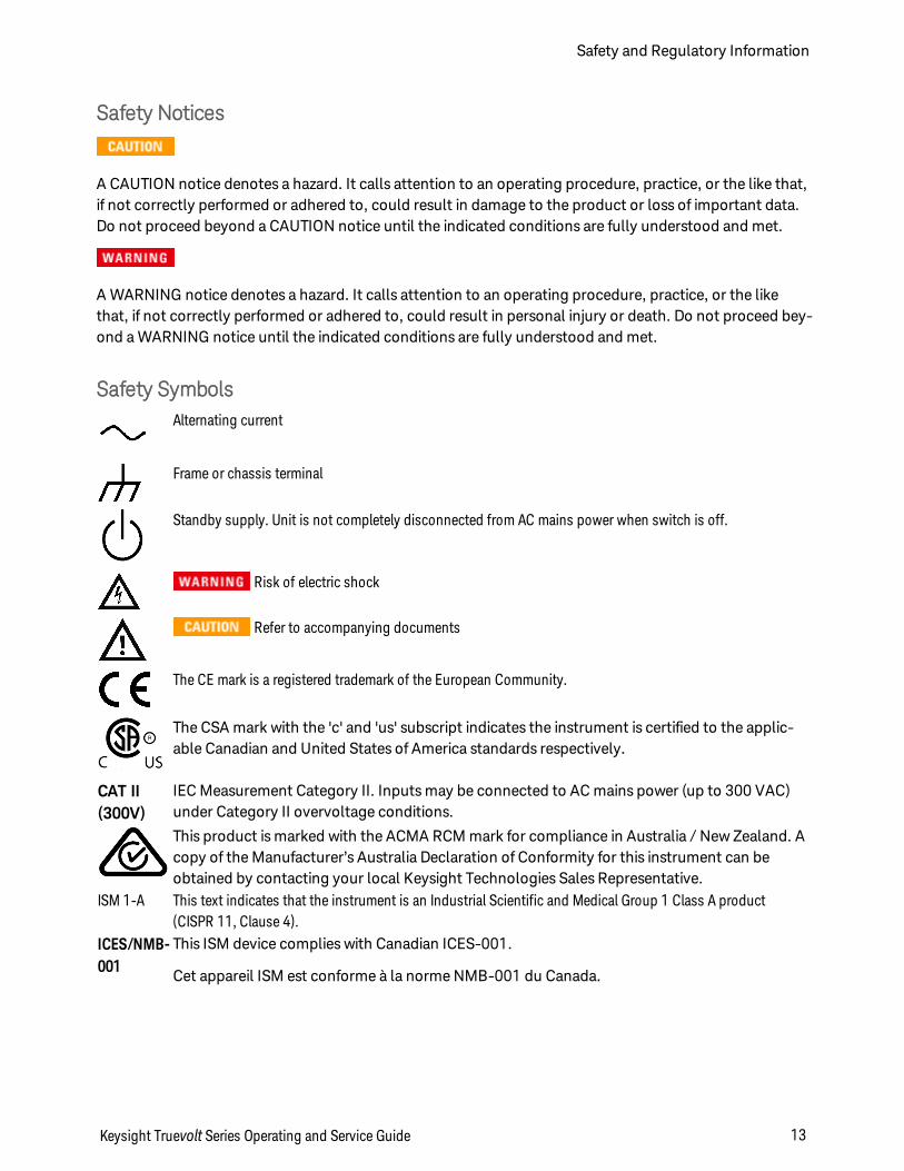
Safety SymbolsAlternating current
Frame or chassis terminal
Standby supply. Unit is not completely disconnected from AC mains power when switch is off.
Risk of electric shock
Refer to accompanying documents
The CE mark is a registered trademark of the European Community.
The CSA mark with the 'c' and 'us' subscript indicates the instrument is certified to the applic-able Canadian and United States of America standards respectively.
CAT II(300V)
IEC Measurement Category II. Inputs may be connected to AC mains power (up to 300 VAC)under Category II overvoltage conditions.
This product is marked with the ACMA RCM mark for compliance in Australia / New Zealand. Acopy of the Manufacturer’s Australia Declaration of Conformity for this instrument can beobtained by contacting your local Keysight Technologies Sales Representative.
ISM 1-A This text indicates that the instrument is an Industrial Scientific and Medical Group 1 Class A product(CISPR 11, Clause 4).
ICES/NMB-001
This ISM device complies with Canadian ICES-001.
Cet appareil ISM est conforme à la norme NMB-001 du Canada.
Keysight Truevolt Series Operating and Service Guide 13
Safety and Regulatory Information
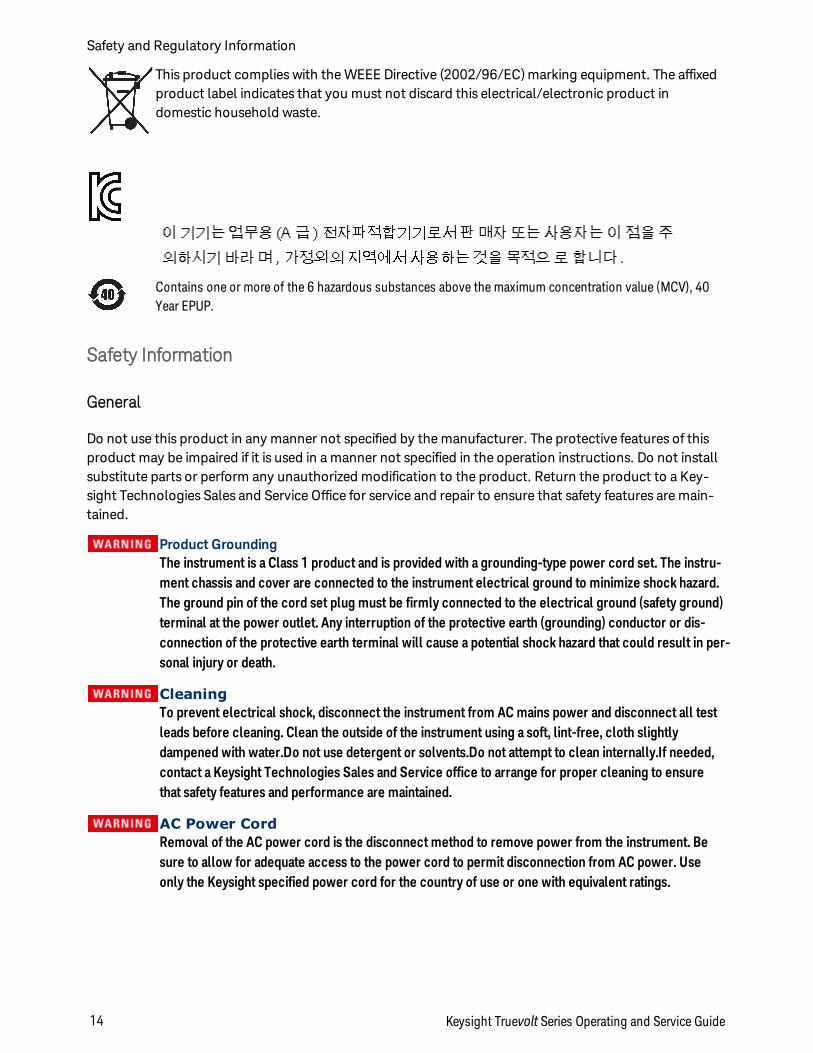
This product complies with the WEEE Directive (2002/96/EC) marking equipment. The affixedproduct label indicates that you must not discard this electrical/electronic product indomestic household waste.
Contains one or more of the 6 hazardous substances above the maximum concentration value (MCV), 40Year EPUP.
Safety Information
General
Do not use this product in any manner not specified by the manufacturer. The protective features of thisproduct may be impaired if it is used in a manner not specified in the operation instructions. Do not installsubstitute parts or perform any unauthorized modification to the product. Return the product to a Key-sight Technologies Sales and Service Office for service and repair to ensure that safety features are main-tained.
Product GroundingThe instrument is a Class 1 product and is provided with a grounding-type power cord set. The instru-ment chassis and cover are connected to the instrument electrical ground to minimize shock hazard.The ground pin of the cord set plug must be firmly connected to the electrical ground (safety ground)terminal at the power outlet. Any interruption of the protective earth (grounding) conductor or dis-connection of the protective earth terminal will cause a potential shock hazard that could result in per-sonal injury or death.
CleaningTo prevent electrical shock, disconnect the instrument from AC mains power and disconnect all testleads before cleaning. Clean the outside of the instrument using a soft, lint-free, cloth slightlydampened with water.Do not use detergent or solvents.Do not attempt to clean internally.If needed,contact a Keysight Technologies Sales and Service office to arrange for proper cleaning to ensurethat safety features and performance are maintained.
AC Power CordRemoval of the AC power cord is the disconnect method to remove power from the instrument. Besure to allow for adequate access to the power cord to permit disconnection from AC power. Useonly the Keysight specified power cord for the country of use or one with equivalent ratings.
Safety and Regulatory Information
14 Keysight Truevolt Series Operating and Service Guide
Do Not Remove Instrument CoverOnly qualified, service-trained personnel should remove the cover from the instrument. Service:Unplug instrument from wall outlet, remove power cord, and remove all probes from all terminalsbefore servicing.
AC Mains Power Line FuseFor continued protection against fire, replace the line fuse only with fuses of the specified type and rat-ing. The instrument must be disconnected from AC mains power, and all measurement terminalsmust be disconnected before changing the fuse.
Current Measurement Protection FuseFor continued protection against fire, replace current-protection fuses only with fuses of the specifiedtype and rating. The instrument must be disconnected from AC mains power, and all measurement ter-minals must be disconnected before changing the fuse.
Front/Rear SwitchDo not change the position of the Front/Rear switch on the front panel while signals are present oneither the front or rear set of terminals. The switch is not intended as an active multiplexer. Switchingwhile current or high voltage is present may cause instrument damage and lead to the risk of electricshock.
Do Not Operate in an Explosive AtmosphereThis instrument is not designed to be operated in an explosive environment. The instrument enclosurecomplies with the IP 20 rating.
In Case of DamageAn instrument that appears damaged or defective should be made inoperative and secured againstunintended operation until qualified service personnel can repair it.
Self-TestBefore measuring any hazardous voltage or current, remove all test leads to the instrument, run theTEST:ALL? query from the remote interface, and read the result to verify that the instrument is per-forming properly.
The TEST:ALL? query is a self-test that returns +0 if the instrument passes and +1 if the instrumentfails. You can also perform this query from the front panel by pressing [Shift] > [Utility] > Test/Admin >Self Test > Full Test. If this self-test fails, make sure that the instrument is repaired and passes thecomplete self-test before continuing.
Measuring AC Power MainsThe HI, LO, and current input terminals may be connected to AC mains power in IEC Category II install-ations for line voltages up to 300 VAC. To avoid the danger of electric shock, do not connect the inputsto AC mains power for line voltages above 300 VAC. See IEC Measurement Category II for furtherinformation.
Keysight Truevolt Series Operating and Service Guide 15
Safety and Regulatory Information
Measuring Current with A Current TransformerIf a current transformer is used for measuring current, you must use a current transformer withinternal secondary protection. Using a current transformer without protection may result in a haz-ardous voltage resulting in a severe shock or death. In addition, this may cause damage to the instru-ment.
Crest FactorExceeding the crest factor limit may result in an inaccurate or lower reading display. Do not exceed the crest factor limit to avoid instrument damage and risk of electric shock.
Measurement LimitsTo avoid instrument damage and the risk of electric shock, do not exceed any of the Measurement Lim-its defined in the following section.
This product complies with EN/IEC 61326-2-1, for sensitive test and measurement equip-ment:
When subjected to transient radiated and/or conducted electromagnetic phenomena, theproduct may have temporary loss of function or performance which is self-recovering. Recov-ery may take longer than 10 seconds.
When subjected to continuously present electromagnetic phenomena, some degradation ofperformance may occur.
Unless otherwise noted in the specifications, this instrument or system is intended for indooruse in an installation category II, pollution degree 2 environment per IEC 61010-1 and 664respectively. It is designed to operate at a maximum relative humidity of 5% to 80% at 40 °C orless (non-condensing). This instrument or system is designed to operate at altitudes up to3000 meters, and at temperatures between 0 and 55 °C.
Measurement Limits
The Truevolt Series DMMs provide protection circuitry to prevent damage to the instrument and to protectagainst the danger of electric shock, provided the Measurement Limits are not exceeded. To ensure safeoperation of the instrument, do not exceed the Measurement Limits shown on the front and rear panel,and defined as follows:
Safety and Regulatory Information
16 Keysight Truevolt Series Operating and Service Guide
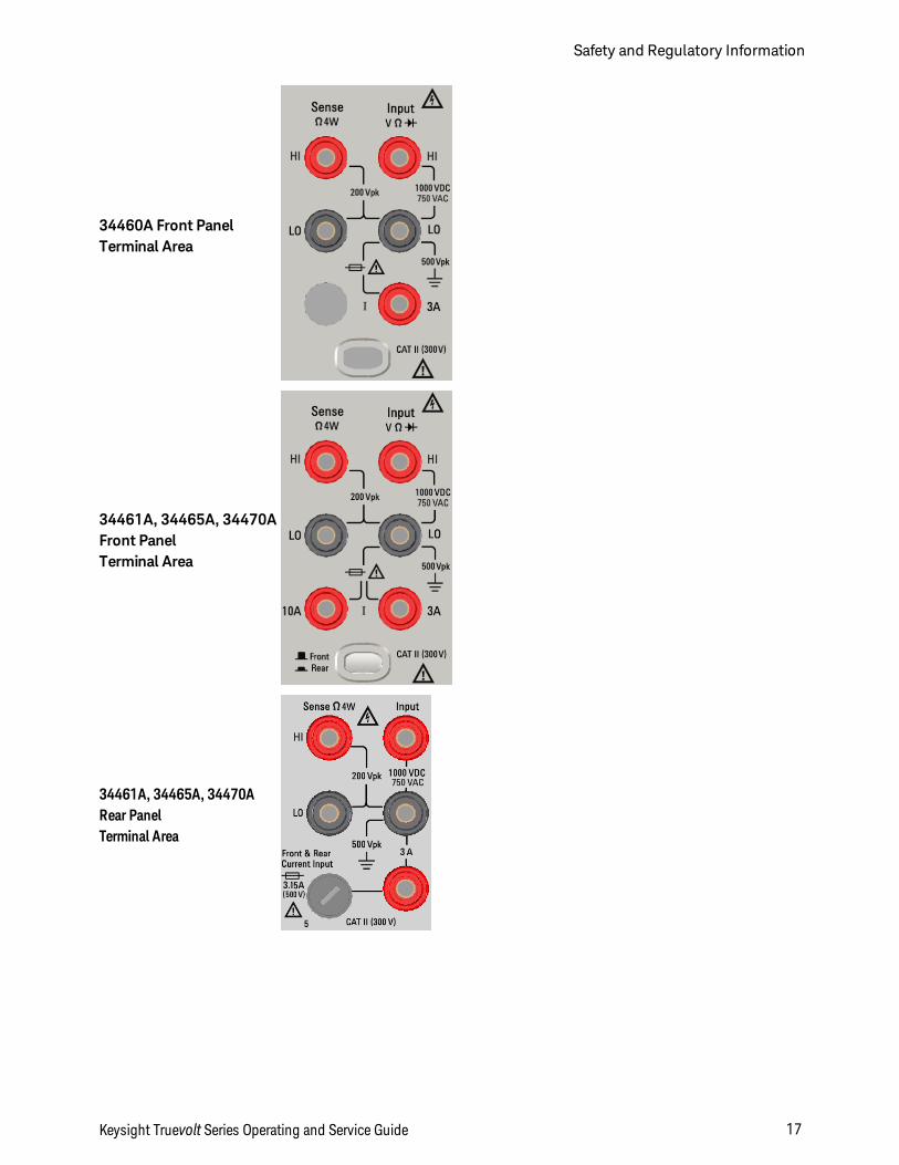
34460A Front PanelTerminal Area
34461A, 34465A, 34470AFront PanelTerminal Area
34461A, 34465A, 34470ARear PanelTerminal Area
Keysight Truevolt Series Operating and Service Guide 17
Safety and Regulatory Information
For the 34461A, 34465A, and 34470A, the Front/Rear switch selects the terminal set to beused. DO NOT operate this switch while signals are present on the front or rear terminals.
The user-replaceable 3 A current-protection fuse is on the rear panel. There are 3 A and 10 A(34461A, 34465A and 34470A) current-protection fuses located inside the unit. Contact yourKeysight Sales and Service Center or refer to product service documentation for replacementinstructions.
To maintain protection, replace fuses only with fuses of the specified type and rating.
Input Terminal Measurement Limits
Measurement Limits are defined for the input terminals:
Main Input (HI and LO) Terminals. The HI and LO input terminals are used for voltage, resistance, fre-quency (period), capacitance, and diode test measurements. Two Measurement Limits are defined forthese terminals:
l HI to LO Measurement Limit. The Measurement Limit from HI to LO (Input terminals) is 1000 VDC or750 VAC, which is also the maximum voltage measurement. This limit can also be expressed as 1000Vpk maximum.
l LO to Ground Measurement Limit. The LO input terminal can safely "float" a maximum of 500 Vpkrelative to ground, where ground is defined as the Protective Earth Conductor in the AC mains powercord connected to the instrument.
As implied by the above limits, the Measurement Limit for the HI input terminal is a maximum of 1500 Vpkrelative to ground when LO is at its maximum of 500 Vpk relative to ground.
Current Input Terminal. The current input ("I") terminal has a Measurement Limit of 3 A or 10 A (DC orAC) between the "I" terminal (3 A or 10 A) and the LO input terminal. Note that the current input terminalswill always be at approximately the same voltage as the LO terminal, unless a current protection fuse isopen. The 10 A terminal is not available on the 34460A.
Sense Terminal Measurement Limits
The HI and LO sense terminals are used for DCV ratio measurements and four-wire resistance and tem-perature measurements. The Measurement Limit is 200 Vpk for all of the terminal pairings: LO sense to LOinput, HI sense to LO input, and HI sense to LO sense.
The 200 Vpk limit on the sense terminals is the Measurement Limit. Operational voltages in resistance meas-urements are much lower – up to ± 12 V in normal operation.
Safety and Regulatory Information
18 Keysight Truevolt Series Operating and Service Guide
IEC Measurement Category II
To protect against the danger of electric shock, the Keysight Truevolt Series DMM protects the user fromAC mains power overvoltage events. When measuring AC mains, the HI and LO input terminals may beconnected to AC mains power up to 300 VAC under Measurement Category II conditions as definedbelow.
IEC Measurement Category II includes electrical devices connected to AC mains power at an outlet on abranch circuit. Such devices include most small appliances, test equipment, and other devices that pluginto a branch outlet or socket. The instrument may be used to make measurements with the HI and LOinputs connected to AC mains power in such devices, or to the branch outlet itself (up to 300 VAC).However, the instrument may not be used with its HI and LO inputs connected to AC mains power in per-manently installed electrical devices such as the main circuit-breaker panel, sub-panel disconnect boxes,or permanently wired motors. Such devices and circuits are subject to overvoltages that may exceed theinstrument’s protection capabilities.
Voltages above 300 VAC may be measured only in circuits that are isolated from AC mains power. However,transient overvoltages are also present on circuits that are isolated from AC mains power. The instrument isdesigned to safely withstand occasional transient overvoltages up to 1500 Vpk when measuring voltagesgreater than 300 VAC. Do not use this equipment to measure circuits where transient overvoltages couldexceed this level.
Keysight 34138A Test Lead Set
The Keysight 34138A Test Lead Set, described below, is compatible with the Truevolt Series DMMs.
Test Lead Ratings
l Test Leads - 1000V, 15A
l Fine Tip Probe Attachments - 300V
l 3A Mini Grabber Attachment - 300V, 3A
l SMT Grabber Attachments - 300V, 3A
Operation
The Fine Tip, Mini Grabber, and SMT Grabber attachments plug onto the probe end of the Test Leads.
Maintenance
If any portion of the Test Lead Set is worn or damaged, do not use. Replace with a new Keysight 34138ATest Lead Set.
If the Test Lead Set is used in amanner not specified by Keysight Technologies, the protectionprovided by the Test Lead Set may be impaired. Also, do not use a damaged or worn Test Lead Set. Per-sonal injury or death may result.
Keysight Truevolt Series Operating and Service Guide 19
Safety and Regulatory Information
Declaration of Conformity
Declarations of Conformity for this product and for other Keysight products may be downloaded from theKeysight Regulatory Web site:
http://regulations.products.keysight.com/DoC/search.htm
Safety and Regulatory Information
20 Keysight Truevolt Series Operating and Service Guide
Welcome
Introductory Information
Safety and Regulatory Information
Models and Options
Quick Start
Contacting Keysight Technologies
Introduction to the Instrument
User Information
Front Panel Menu Reference
Features and Functions
Remote Interface Configuration
LAN Configuration Procedure
Web Interface
Measurements
Triggering and Readings
Probe Hold
Math
Display
Utility Menu
Measurement Tutorial
Keysight Truevolt Series Operating and Service Guide 21
Welcome
SCPI Programming Reference
Welcome to SCPI
Introduction to the SCPI Language
Commands by Subsystem
Command Quick Reference
Range, Resolution, and NPLC
Resolution Table
VM Comp Output
SCPI Error Messages
Power-On and Reset State
Service and Repair
Service and Repair
Disassembly
Troubleshooting
Power Supplies
Self-Test Procedures
Battery Replacement
Installing the Optional GPIB Interface
User Replaceable Parts
Performance Verification
Performance Verification
Calibration Procedures
Calibration Procedures
34460A and 34461A Calibration Procedures
34465A and 34470A Calibration Procedures
Firmware Update
Welcome
22 Keysight Truevolt Series Operating and Service Guide
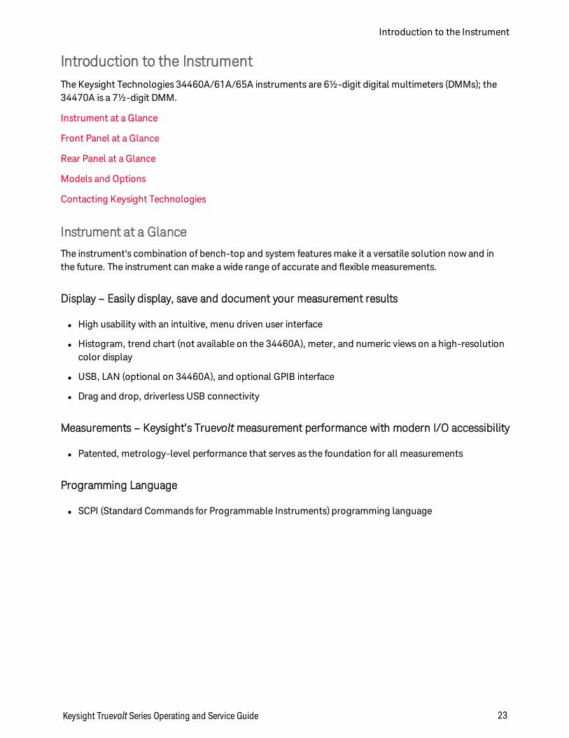
Introduction to the InstrumentThe Keysight Technologies 34460A/61A/65A instruments are 6½-digit digital multimeters (DMMs); the34470A is a 7½-digit DMM.
Instrument at a Glance
Front Panel at a Glance
Rear Panel at a Glance
Models and Options
Contacting Keysight Technologies
Instrument at a Glance
The instrument’s combination of bench-top and system features make it a versatile solution now and inthe future. The instrument can make a wide range of accurate and flexible measurements.
Display – Easily display, save and document your measurement results
l High usability with an intuitive, menu driven user interface
l Histogram, trend chart (not available on the 34460A), meter, and numeric views on a high-resolutioncolor display
l USB, LAN (optional on 34460A), and optional GPIB interface
l Drag and drop, driverless USB connectivity
Measurements – Keysight’s Truevoltmeasurement performance with modern I/O accessibility
l Patented, metrology-level performance that serves as the foundation for all measurements
Programming Language
l SCPI (Standard Commands for Programmable Instruments) programming language
Keysight Truevolt Series Operating and Service Guide 23
Introduction to the Instrument
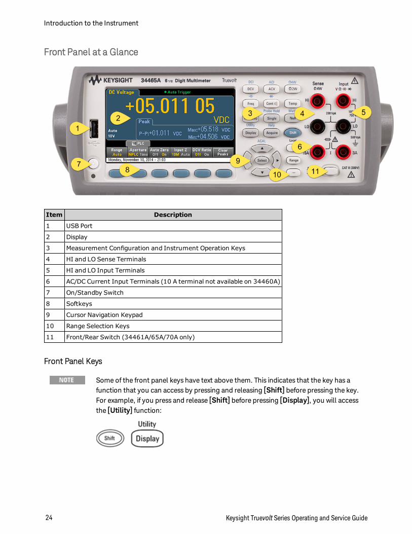
Front Panel at a Glance
Item Description
1 USB Port
2 Display
3 Measurement Configuration and Instrument Operation Keys
4 HI and LO Sense Terminals
5 HI and LO Input Terminals
6 AC/DC Current Input Terminals (10 A terminal not available on 34460A)
7 On/Standby Switch
8 Softkeys
9 Cursor Navigation Keypad
10 Range Selection Keys
11 Front/Rear Switch (34461A/65A/70A only)
Front Panel Keys
Some of the front panel keys have text above them. This indicates that the key has afunction that you can access by pressing and releasing [Shift] before pressing the key.For example, if you press and release [Shift] before pressing [Display], you will accessthe [Utility] function:
Introduction to the Instrument
24 Keysight Truevolt Series Operating and Service Guide
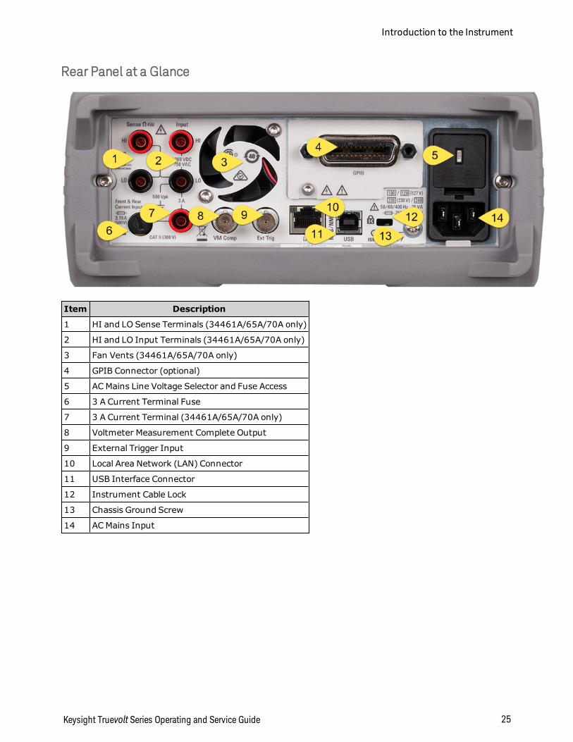
Rear Panel at a Glance
Item Description
1 HI and LO Sense Terminals (34461A/65A/70A only)
2 HI and LO Input Terminals (34461A/65A/70A only)
3 Fan Vents (34461A/65A/70A only)
4 GPIB Connector (optional)
5 AC Mains Line Voltage Selector and Fuse Access
6 3 A Current Terminal Fuse
7 3 A Current Terminal (34461A/65A/70A only)
8 Voltmeter Measurement Complete Output
9 External Trigger Input
10 Local Area Network (LAN) Connector
11 USB Interface Connector
12 Instrument Cable Lock
13 Chassis Ground Screw
14 AC Mains Input
Keysight Truevolt Series Operating and Service Guide 25
Introduction to the Instrument
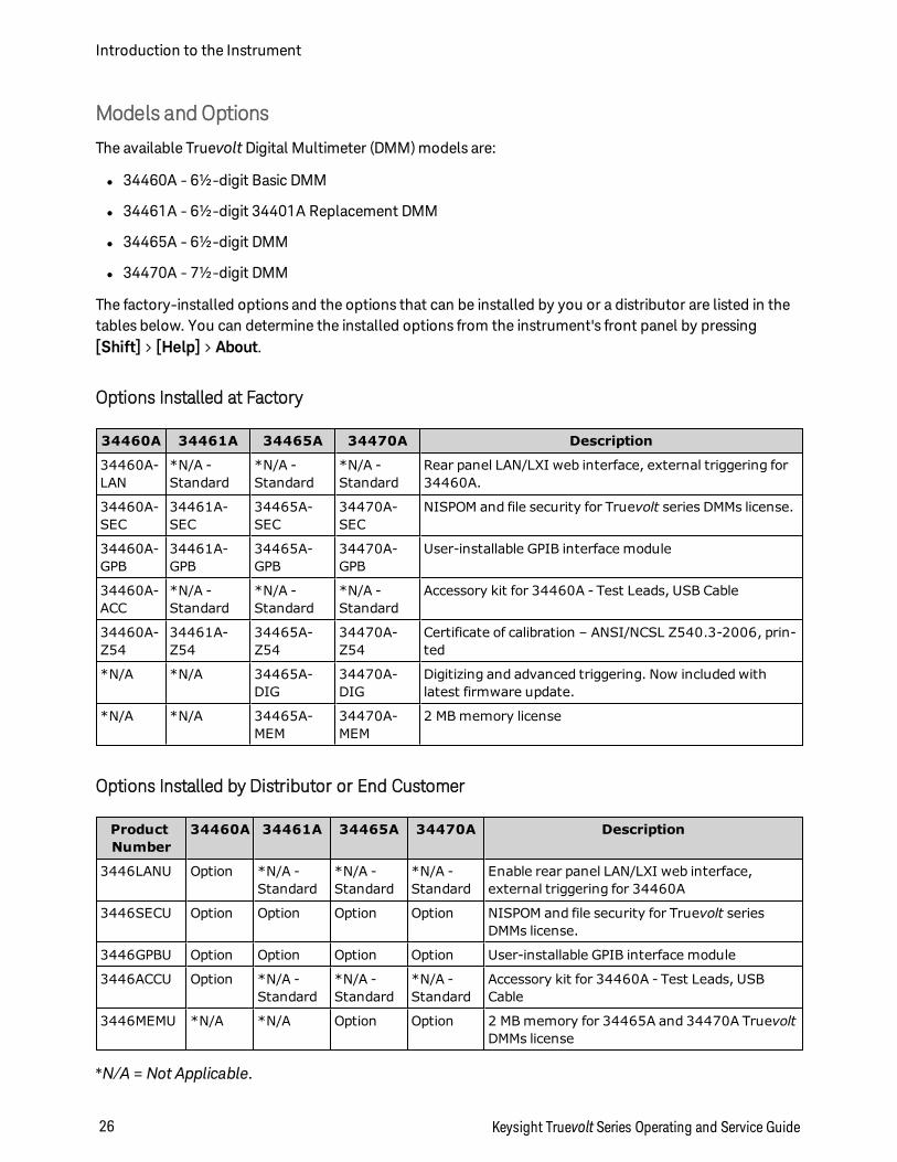
Models and Options
The available Truevolt Digital Multimeter (DMM) models are:
l 34460A - 6½-digit Basic DMM
l 34461A - 6½-digit 34401A Replacement DMM
l 34465A - 6½-digit DMM
l 34470A - 7½-digit DMM
The factory-installed options and the options that can be installed by you or a distributor are listed in thetables below. You can determine the installed options from the instrument's front panel by pressing[Shift] > [Help] > About.
Options Installed at Factory
34460A 34461A 34465A 34470A Description
34460A-LAN
*N/A -Standard
*N/A -Standard
*N/A -Standard
Rear panel LAN/LXI web interface, external triggering for34460A.
34460A-SEC
34461A-SEC
34465A-SEC
34470A-SEC
NISPOM and file security for Truevolt series DMMs license.
34460A-GPB
34461A-GPB
34465A-GPB
34470A-GPB
User-installable GPIB interface module
34460A-ACC
*N/A -Standard
*N/A -Standard
*N/A -Standard
Accessory kit for 34460A - Test Leads, USB Cable
34460A-Z54
34461A-Z54
34465A-Z54
34470A-Z54
Certificate of calibration – ANSI/NCSL Z540.3-2006, prin-ted
*N/A *N/A 34465A-DIG
34470A-DIG
Digitizing and advanced triggering. Now included withlatest firmware update.
*N/A *N/A 34465A-MEM
34470A-MEM
2 MB memory license
Options Installed by Distributor or End Customer
ProductNumber
34460A 34461A 34465A 34470A Description
3446LANU Option *N/A -Standard
*N/A -Standard
*N/A -Standard
Enable rear panel LAN/LXI web interface,external triggering for 34460A
3446SECU Option Option Option Option NISPOM and file security for Truevolt seriesDMMs license.
3446GPBU Option Option Option Option User-installable GPIB interface module
3446ACCU Option *N/A -Standard
*N/A -Standard
*N/A -Standard
Accessory kit for 34460A - Test Leads, USBCable
3446MEMU *N/A *N/A Option Option 2 MB memory for 34465A and 34470A TruevoltDMMs license
*N/A = Not Applicable.
Introduction to the Instrument
26 Keysight Truevolt Series Operating and Service Guide
Remote Interface ConfigurationIf you have the security option installed on your instrument, the instrument must be unsecured with thesecurity code to perform many of these actions.
The instrument supports remote interface communication over three interfaces: GPIB (optional), USB, andLAN (optional on 34460A). All three are "live" at power up when the instrument ships from the factory.
l GPIB Interface: Set the instrument's GPIB address and connect to your PC using a GPIB cable.
l USB Interface: Use the rear-panel USB connector to communicate with your PC. For details, see USBSettings.
l LAN Interface: By default, DHCP is on, which may enable communication over LAN. The acronymDHCP stands for Dynamic Host Configuration Protocol, a protocol for assigning dynamic IP addressesto networked devices. With dynamic addressing, a device can have a different IP address every time itconnects to the network.
Connectivity Software
l The instrument ships with the Keysight Automation-Ready CD. This CD contains Keysight IO Librar-ies Suite software, which must be installed to enable remote-interface operations. The CD auto-startsand provides information on installing the software. Also includesKeysight TechnologiesUSB/LAN/GPIB Connectivity Guide, which contains additional information.
GPIB Configuration
Each device on the GPIB (IEEE-488) interface must have a unique whole number address between 0 and30. The instrument ships with a default address of 10, and the GPIB address is displayed at power-on.
l This setting is non-volatile; it will not be changed by power cycling or *RST or SYSTem:PRESet.
l Your computer’s GPIB interface card address must not conflict with any instrument on the interfacebus.
l Front Panel: Press [Utility] > I/O Config > GPIB Settings. From this menu, you can set the GPIBaddress and turn GPIB on or off. After making changes, you must cycle power on the instrument forthe change to take effect.
l SCPI:SYSTem:COMMunicate:GPIB:ADDRess <address>SYSTem:COMMunicate:ENABle ON|1|OFF|0,GPIB
Keysight Truevolt Series Operating and Service Guide 27
Introduction to the Instrument
LAN Configuration
The following sections describe the primary front panel LAN configuration functions, including SCPI com-mands where applicable. Some LAN configuration functions can be performed only via SCPI. See SYSTemSubsystem - I/O Configuration for all LAN configuration commands, and see LAN Configuration Pro-cedure to configure the LAN via the front panel.
Some LAN settings require you to cycle instrument power to activate them. The instru-ment briefly displays a message when this is the case, so watch the screen closely asyou change LAN settings.
Resetting the LAN
You can clear the Web Interface password, turn DHCP on, and restart the LAN at any time:
l Front Panel:[Utility] > I/O Config > LAN Reset
The message "Performing LAN Reset" is displayed while the LAN is reset.
l SCPI: LXI:RESet
DHCP On/Off
DHCP (Dynamic Host Configuration Protocol) can automatically assign a dynamic IP address to a LANdevice. This is typically the easiest way to configure the instrument for LAN.
l This setting is non-volatile; it will not be changed by power cycling or *RST or SYSTem:PRESet.
l Front Panel:[Utility] > I/O Config > LAN Settings > Modify SettingsThen set the first softkey to DHCP to use DHCP to automatically assign an IP address.
l SCPI: SYSTem:COMMunicate:LAN:DHCP ON|1|OFF|0
l If you change this parameter, you must either press the Apply Changes softkey (front panel) or sendSYSTem:COMMunicate:LAN:UPDate (remote interface) for the change to take effect.
To manually set an IP address, Subnet Mask, or Default Gateway, turn DHCP off, then change the IP setupas described below.
Introduction to the Instrument
28 Keysight Truevolt Series Operating and Service Guide
IP Address
You can enter a static IP address for the instrument as a four-byte integer expressed in dot notation. Eachbyte is a decimal value, with no leading zeros (for example, 169.254.2.20).
l If DHCP is on, it attempts to assign an IP address to the instrument. If it fails, Auto-IP attempts toassign an IP address to the instrument.
l Contact your LAN administrator to obtain an IP address.
l This setting is non-volatile; it will not be changed by power cycling or *RST or SYSTem:PRESet.
l Front Panel:[Utility] > I/O Config > LAN Settings > Modify SettingsThen set the first softkey to Manual and press IP Address to enter a new IP address.
l SCPI: SYSTem:COMMunicate:LAN:IPADdress "<address>"
l If you change this parameter, you must either press the Apply Changes softkey (front panel) or sendSYSTem:COMMunicate:LAN:UPDate (remote interface) for the change to take effect.
Subnet Mask
Subnetting allows the LAN administrator to subdivide a network to simplify administration and minimizenetwork traffic. The subnet mask indicates the portion of the host address used to indicate the subnet.
l Contact your LAN administrator for details.
l This setting is non-volatile; it will not be changed by power cycling or *RST or SYSTem:PRESet.
l Front Panel:[Utility] > I/O Config > LAN Settings > Modify SettingsThen set the first softkey to Manual and press Subnet Mask to enter a new subnet mask with thearrow keys (for example: 255.255.0.0).
l SCPI: SYSTem:COMMunicate:LAN:SMASk "<mask>"
l If you change this parameter, you must either press the Apply Changes softkey (front panel) or sendSYSTem:COMMunicate:LAN:UPDate (remote interface) for the change to take effect.
Keysight Truevolt Series Operating and Service Guide 29
Introduction to the Instrument
Default Gateway
A gateway is a network device that connects networks. The default gateway setting is the IP address ofsuch a device.
l You need not set a gateway address if using DHCP.
l Contact your LAN administrator for details.
l This setting is non-volatile; it will not be changed by power cycling or *RST or SYSTem:PRESet.
l Front Panel:[Utility] > I/O Config > LAN Settings > Modify SettingsThen set the first softkey to Manual and press More and Gateway. Then set the appropriate gatewayaddress using the arrow keys.
l SCPI: SYSTem:COMMunicate:LAN:GATeway "<address>"
l If you change this parameter, you must either press the Apply Changes softkey (front panel) or sendSYSTem:COMMunicate:LAN:UPDate (remote interface) for the change to take effect.
Hostname
A hostname is the host portion of the domain name, which is translated into an IP address.
l The instrument receives a unique hostname at the factory, but you may change it. The hostname mustbe unique on the LAN.
l The name must start with letter; other characters can be an upper or lower case letters, numeric digits,or dashes ("-").
l This setting is non-volatile; it will not be changed by power cycling or *RST or SYSTem:PRESet.
l Front Panel:[Utility] > I/O Config > LAN Settings > Modify SettingsThen press Host Name and enter the hostname with the front panel arrow keys.
l SCPI: SYSTem:COMMunicate:LAN:HOSTname "<name>"
l If you change this parameter, you must either press the Apply Changes softkey (front panel) or sendSYSTem:COMMunicate:LAN:UPDate (remote interface) for the change to take effect.
Domain Name
A domain name is a registered Internet name that gets translated into an IP address. You cannot set it fromthe front panel or SCPI.
Introduction to the Instrument
30 Keysight Truevolt Series Operating and Service Guide
DNS Server
DNS (Domain Name Service) is an Internet service that translates domain names into IP addresses. TheDNS server address is the IP address of a server that performs this service.
l Normally, DHCP discovers DNS address information; you only need to change this if DHCP is unusedor not functional. Contact your LAN administrator for details.
l This setting is non-volatile; it will not be changed by power cycling or *RST or SYSTem:PRESet.
l Front Panel:[Utility] > I/O Config > LAN Settings > Modify SettingsThen set the first softkey to Manual and press More and Primary DNS or Second DNS to enter a DNSaddress using the front panel arrow keys.
l SCPI: SYSTem:COMMunicate:LAN:DNS[1|2] "<address>"
l If you change this parameter, you must either press the Apply Changes softkey (front panel) or sendSYSTem:COMMunicate:LAN:UPDate (remote interface) for the change to take effect.
Current Configuration (LAN)
l Press [Utility] > I/O Config > LAN Settings to view the MAC address and current LAN configuration.There is no equivalent SCPI command.
l If the instrument goes into remote, all LAN changes will be canceled and the display will go to a dif-ferent screen. Re-selecting the LAN Settings page will display the new settings if a LAN restart tookplace.
Web Interface
The instrument includes a built-in Web Interface for remote instrument access and control over LAN via aWeb browser. For details, see Web Interface.
Keysight Truevolt Series Operating and Service Guide 31
Introduction to the Instrument
LAN Configuration Procedure
There are several parameters that you might need to set to establish network communication using theLAN interface. Primarily, you will need to establish an IP address. You might need to contact your networkadministrator for help in establishing communication with the LAN interface.
If your instrument has the secure (SEC) option, the instrument must be unsecured to change most LAN set-tings.
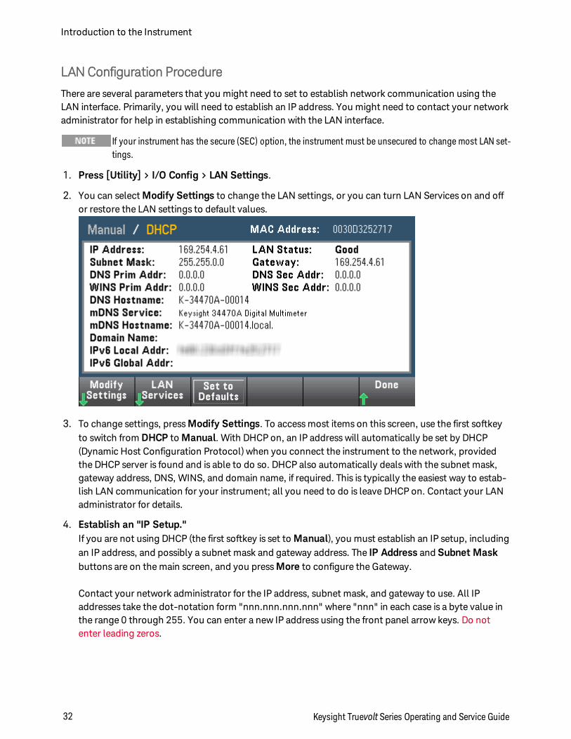
1. Press [Utility] > I/O Config > LAN Settings.
2. You can select Modify Settings to change the LAN settings, or you can turn LAN Services on and offor restore the LAN settings to default values.
3. To change settings, press Modify Settings. To access most items on this screen, use the first softkeyto switch from DHCP to Manual. With DHCP on, an IP address will automatically be set by DHCP(Dynamic Host Configuration Protocol) when you connect the instrument to the network, providedthe DHCP server is found and is able to do so. DHCP also automatically deals with the subnet mask,gateway address, DNS, WINS, and domain name, if required. This is typically the easiest way to estab-lish LAN communication for your instrument; all you need to do is leave DHCP on. Contact your LANadministrator for details.
4. Establish an "IP Setup."If you are not using DHCP (the first softkey is set to Manual), you must establish an IP setup, includingan IP address, and possibly a subnet mask and gateway address. The IP Address and Subnet Maskbuttons are on the main screen, and you press More to configure the Gateway.
Contact your network administrator for the IP address, subnet mask, and gateway to use. All IPaddresses take the dot-notation form "nnn.nnn.nnn.nnn" where "nnn" in each case is a byte value inthe range 0 through 255. You can enter a new IP address using the front panel arrow keys. Do notenter leading zeros.
Introduction to the Instrument
32 Keysight Truevolt Series Operating and Service Guide
5. Configure the "DNS Setup" (optional)DNS (Domain Name Service) is an Internet service that translates domain names into IP addresses. Askyour network administrator whether DNS is in use, and if it is, for the host name, domain name, andDNS server address to use.
a. Set the "hostname." Press Host Name and enter the hostname. A hostname is the host portion ofthe domain name, which is translated into an IP address. The hostname is entered as a string usingthe front panel arrow keys to select and change characters. The hostname may include letters,numbers, and dashes ("-").
b. Set the "DNS Server" addresses. From the LAN configuration screen, press More to go to thesecond of three sets of softkeys.
Enter the Primary DNS and Second DNS. See your network administrator for details.
More about IP Addresses and Dot Notation
Dot-notation addresses ("nnn.nnn.nnn.nnn" where "nnn" is a byte value from 0 to 255) must be expressedwith care, as most PC web software interprets byte values with leading zeros as octal (base 8) numbers. Forexample, "192.168.020.011" is actually equivalent to decimal "192.168.16.9" because ".020" is inter-preted as "16" expressed in octal, and ".011" as "9". To avoid confusion, use only decimal values from 0 to255, with no leading zeros.
Keysight Truevolt Series Operating and Service Guide 33
Introduction to the Instrument
Firmware Update
Use the following procedure to update instrument firmware:
Do not turn off the instrument during the update.
1. Press [Help] > About to determine what instrument firmware version is currently installed.
2.
3. Unzip the ZIP file and use the firmware update utility to prepare a USB drive with the updated firm-ware:
4. Attach the USB drive to the instrument front panel and press [Utility] > Test / Admin > FirmwareUpdate to update the firmware. If the security option is installed, unlock the instrument with the secur-ity code before installing firmware.
Important: In order to update the instrument firmware from remote, the model number in the *IDN?response must match the actual instrument model number. If you have changed the instrument's *IDN?response to another instrument, when attempting to update the firmware from remote, you will see thiserror: The instrument is not supported by this firmware file. To update the firmware, either update usingthe front panel procedure or, from remote, use SYSTem:IDENtify to set the *IDN? to match the actualmodel number, update the firmware, and then use SYSTem:IDENtify again to set the *IDN? response to theother model number.
Introduction to the Instrument
34 Keysight Truevolt Series Operating and Service Guide

Keysight Truevolt Series Operating and Service Guide 35
Introduction to the Instrument
Quick StartThis section describes basic procedures to help you get started quickly with the instrument.
l Prepare Instrument for Use
l Adjust the Carrying Handle
l Use Built-in Help System
l Rack Mount the Instrument
Prepare Instrument for Use
Verify that you received the following items. If anything is missing, please contact your nearest Keysightsales office or Keysight authorized reseller.
l Power cord (for country of destination)
l Certificate of Calibration (optional)
l Keysight Automation-Ready CD (Keysight IO Libraries Suite) (optional on 34460A)
l Supplemental documentation packet
l USB 2.0 cable (optional on 34460A)
Quick Start
36 Keysight Truevolt Series Operating and Service Guide
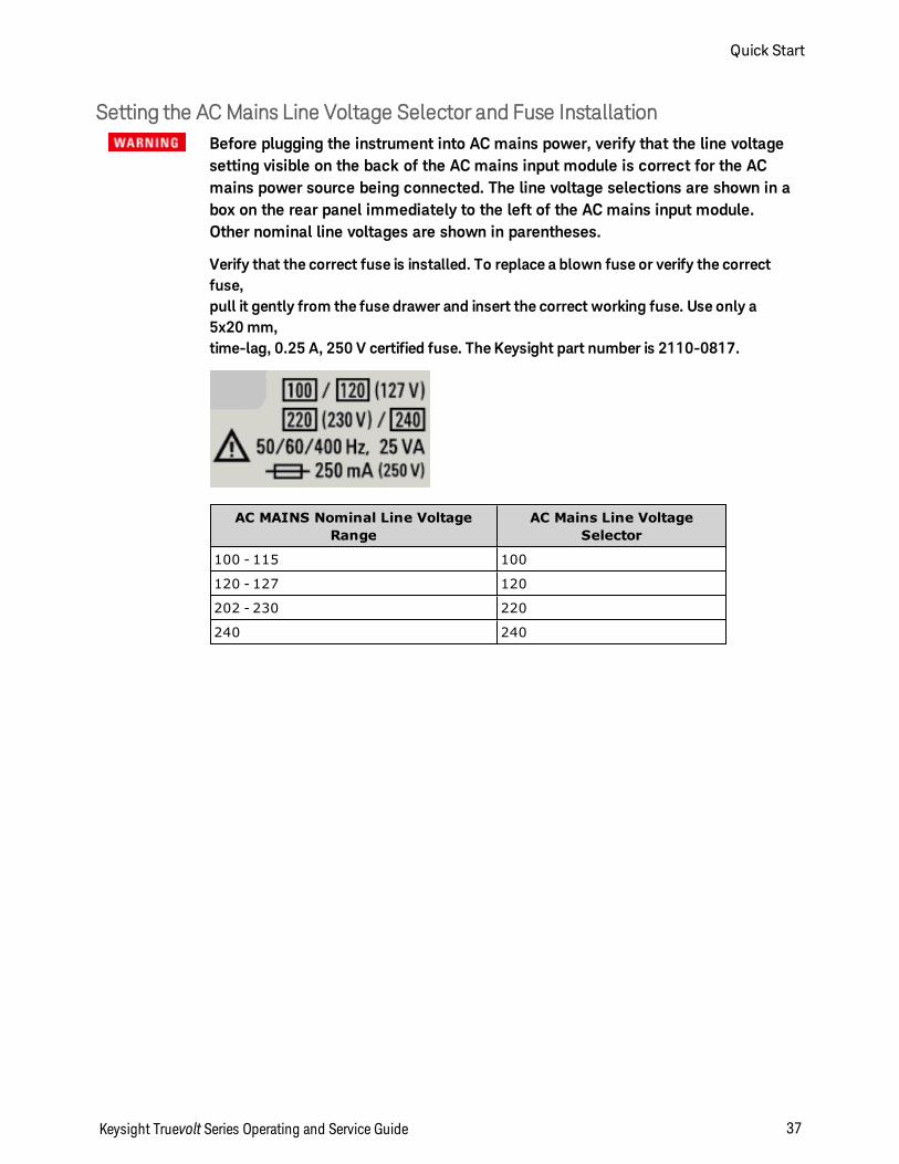
Setting the ACMains Line Voltage Selector and Fuse InstallationBefore plugging the instrument into AC mains power, verify that the line voltagesetting visible on the back of the AC mains input module is correct for the ACmains power source being connected. The line voltage selections are shown in abox on the rear panel immediately to the left of the AC mains input module.Other nominal line voltages are shown in parentheses.
Verify that the correct fuse is installed. To replace a blown fuse or verify the correctfuse,pull it gently from the fuse drawer and insert the correct working fuse. Use only a5x20 mm,time-lag, 0.25 A, 250 V certified fuse. The Keysight part number is 2110-0817.
AC MAINS Nominal Line VoltageRange
AC Mains Line VoltageSelector
100 - 115 100
120 - 127 120
202 - 230 220
240 240
Keysight Truevolt Series Operating and Service Guide 37
Quick Start
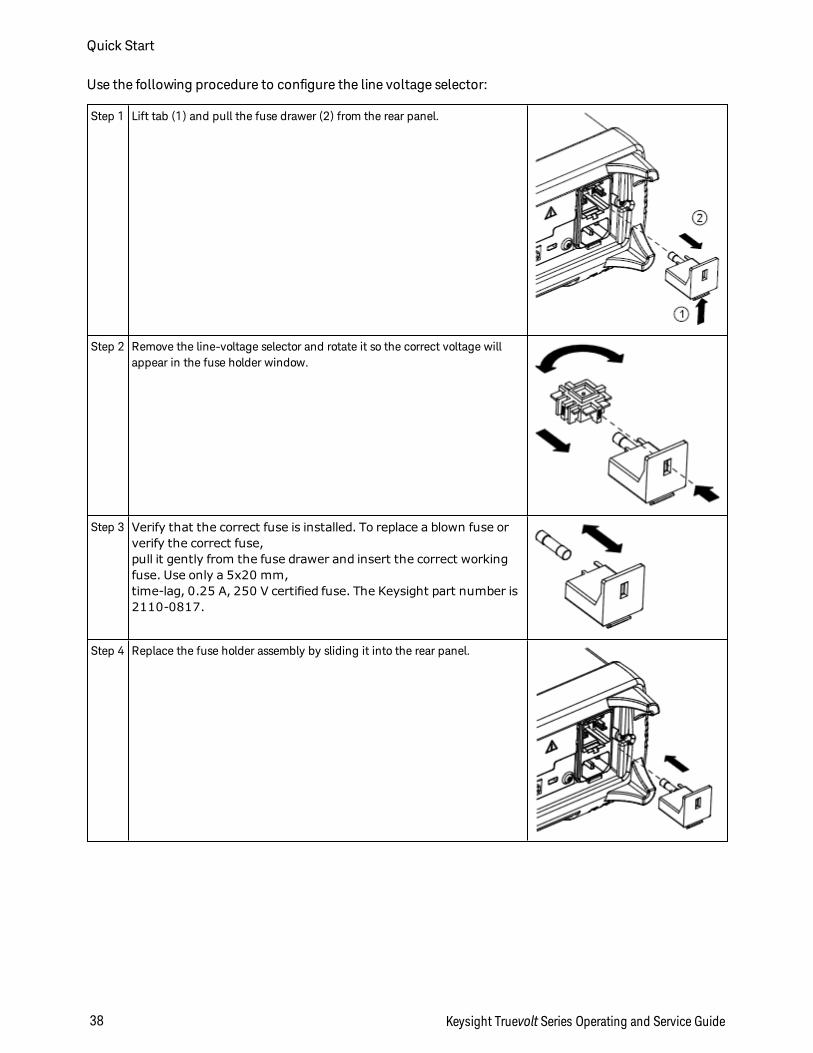
Use the following procedure to configure the line voltage selector:
Step 1 Lift tab (1) and pull the fuse drawer (2) from the rear panel.
Step 2 Remove the line-voltage selector and rotate it so the correct voltage willappear in the fuse holder window.
Step 3 Verify that the correct fuse is installed. To replace a blown fuse orverify the correct fuse,pull it gently from the fuse drawer and insert the correct workingfuse. Use only a 5x20 mm,time-lag, 0.25 A, 250 V certified fuse. The Keysight part number is2110-0817.
Step 4 Replace the fuse holder assembly by sliding it into the rear panel.
Quick Start
38 Keysight Truevolt Series Operating and Service Guide
Product GroundingThe instrument is a Class 1 product and is provided with a grounding-type power cord set. The instru-ment chassis and cover are connected to the instrument electrical ground to minimize shock hazard.The ground pin of the cord set plug must be firmly connected to the electrical ground (safety ground)terminal at the power outlet. Any interruption of the protective earth (grounding) conductor or dis-connection of the protective earth terminal will cause a potential shock hazard that could result in per-sonal injury or death.
Connect Power and I/O Cables
Connect the power cord and LAN, GPIB, or USB cable as desired. After you turn on the instrument (asdescribed below), the instrument will run a power-on self test and then display a message about how toobtain help, along with the current IP address. It also displays the GPIB address (if applicable).
The instrument's default measurement function is DC Voltage (DCV), with autoranging enabled.
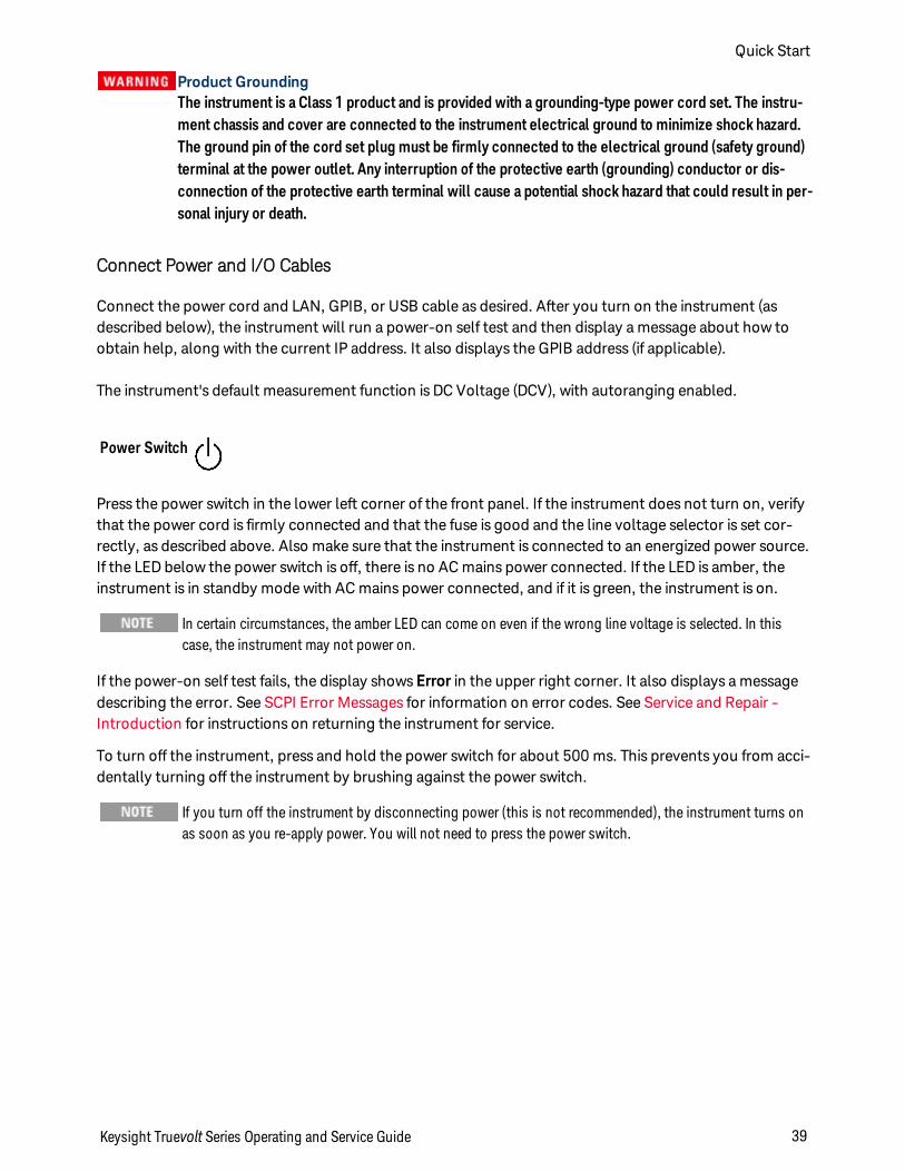
Power Switch
Press the power switch in the lower left corner of the front panel. If the instrument does not turn on, verifythat the power cord is firmly connected and that the fuse is good and the line voltage selector is set cor-rectly, as described above. Also make sure that the instrument is connected to an energized power source.If the LED below the power switch is off, there is no AC mains power connected. If the LED is amber, theinstrument is in standby mode with AC mains power connected, and if it is green, the instrument is on.
In certain circumstances, the amber LED can come on even if the wrong line voltage is selected. In thiscase, the instrument may not power on.
If the power-on self test fails, the display shows Error in the upper right corner. It also displays a messagedescribing the error. See SCPI Error Messages for information on error codes. See Service and Repair -Introduction for instructions on returning the instrument for service.
To turn off the instrument, press and hold the power switch for about 500 ms. This prevents you from acci-dentally turning off the instrument by brushing against the power switch.
If you turn off the instrument by disconnecting power (this is not recommended), the instrument turns onas soon as you re-apply power. You will not need to press the power switch.
Keysight Truevolt Series Operating and Service Guide 39
Quick Start
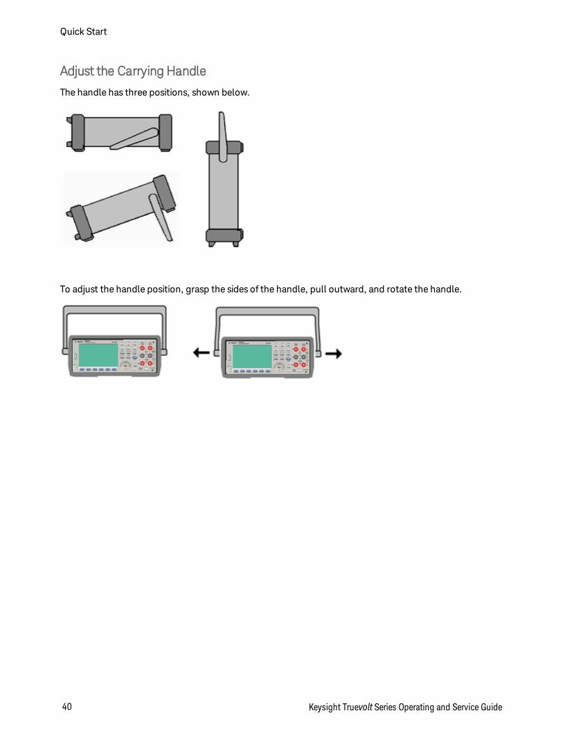
Adjust the Carrying Handle
The handle has three positions, shown below.
To adjust the handle position, grasp the sides of the handle, pull outward, and rotate the handle.
Quick Start
40 Keysight Truevolt Series Operating and Service Guide
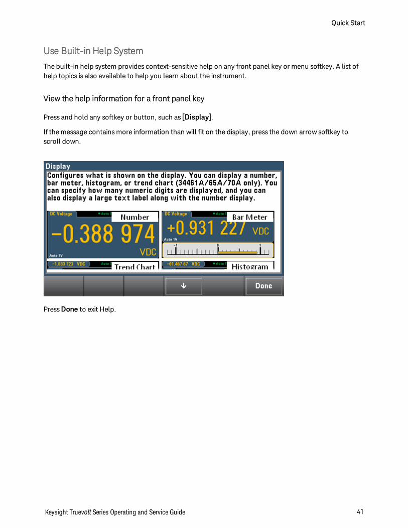
Use Built-in Help System
The built-in help system provides context-sensitive help on any front panel key or menu softkey. A list ofhelp topics is also available to help you learn about the instrument.
View the help information for a front panel key
Press and hold any softkey or button, such as [Display].
If the message contains more information than will fit on the display, press the down arrow softkey toscroll down.
Press Done to exit Help.
Keysight Truevolt Series Operating and Service Guide 41
Quick Start
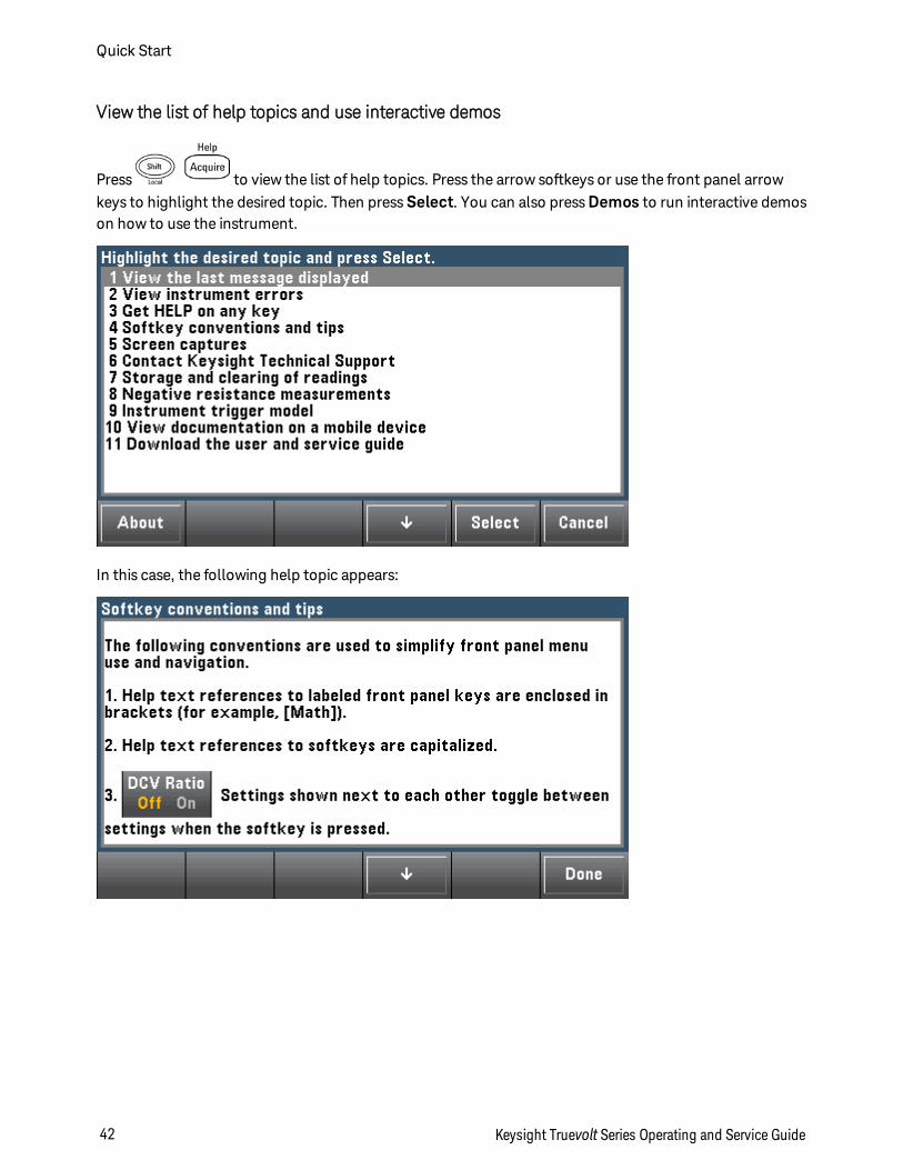
View the list of help topics and use interactive demos
Press to view the list of help topics. Press the arrow softkeys or use the front panel arrowkeys to highlight the desired topic. Then press Select. You can also press Demos to run interactive demoson how to use the instrument.
In this case, the following help topic appears:
Quick Start
42 Keysight Truevolt Series Operating and Service Guide
View the list of recent instrument errors.
Press and choose View instrument errors from the list of help topics. This displays theinstrument's error queue, which includes up to 20 errors.
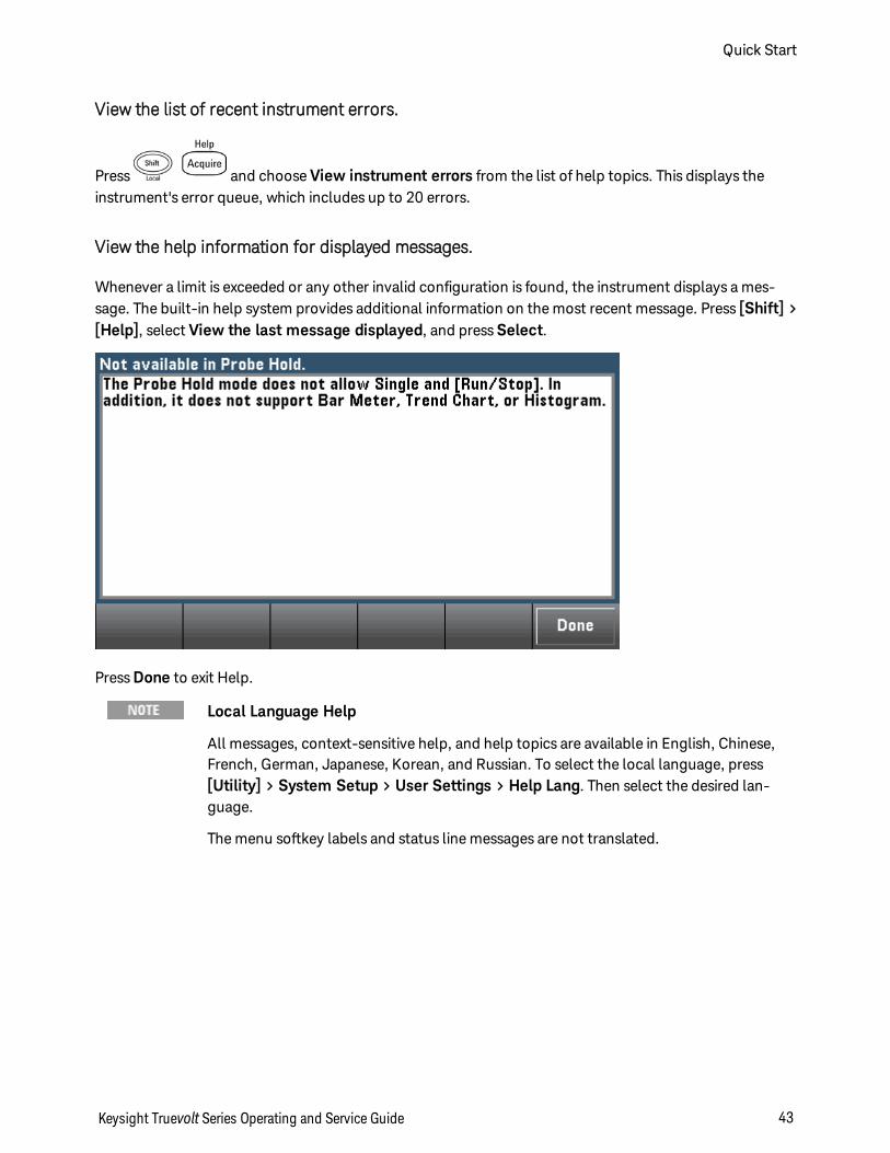
View the help information for displayed messages.
Whenever a limit is exceeded or any other invalid configuration is found, the instrument displays a mes-sage. The built-in help system provides additional information on the most recent message. Press [Shift] >[Help], select View the last message displayed, and press Select.
Press Done to exit Help.
Local Language Help
All messages, context-sensitive help, and help topics are available in English, Chinese,French, German, Japanese, Korean, and Russian. To select the local language, press[Utility] > System Setup > User Settings > Help Lang. Then select the desired lan-guage.
The menu softkey labels and status line messages are not translated.
Keysight Truevolt Series Operating and Service Guide 43
Quick Start
Rack Mount the Instrument
You can mount the instrument in a standard 19-inch rack cabinet using one of two optional kits, each ofwhich includes instructions and mounting hardware. You may also mount Another Keysight System IIinstrument of the same height and width beside the instrument.
To prevent overheating, do not block airflow to or from the instrument. Allow enoughclearance at the rear, sides, and bottom of the instrument to permit adequate internalair flow.
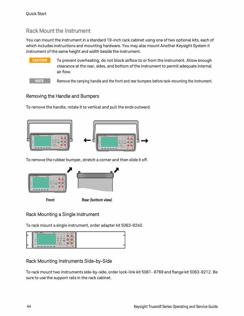
Remove the carrying handle and the front and rear bumpers before rack-mounting the instrument.
Removing the Handle and Bumpers
To remove the handle, rotate it to vertical and pull the ends outward.
To remove the rubber bumper, stretch a corner and then slide it off.
Front Rear (bottom view)
Rack Mounting a Single Instrument
To rack mount a single instrument, order adapter kit 5063-9240.
Rack Mounting Instruments Side-by-Side
To rack mount two instruments side-by-side, order lock-link kit 5061- 8769 and flange kit 5063-9212. Besure to use the support rails in the rack cabinet.
Quick Start
44 Keysight Truevolt Series Operating and Service Guide
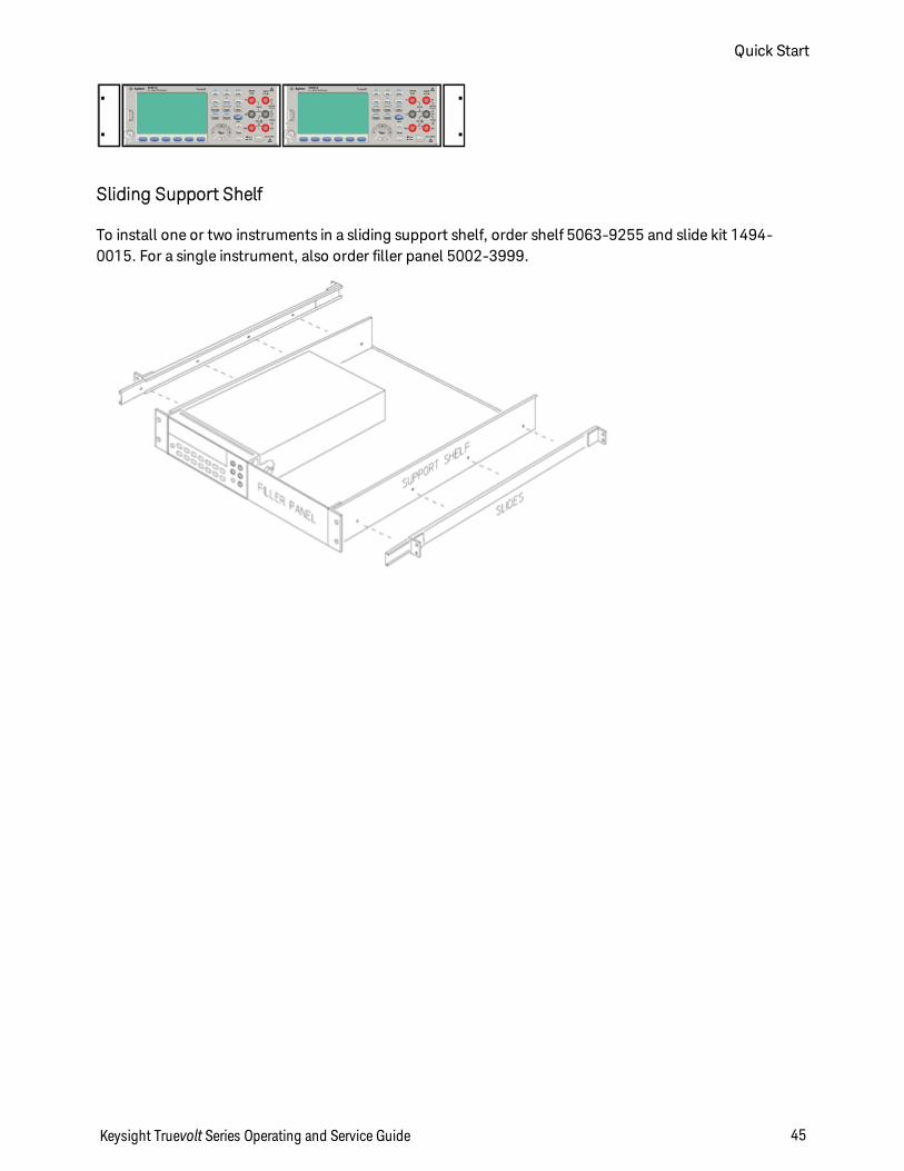
Sliding Support Shelf
To install one or two instruments in a sliding support shelf, order shelf 5063-9255 and slide kit 1494-0015. For a single instrument, also order filler panel 5002-3999.
Keysight Truevolt Series Operating and Service Guide 45
Quick Start
Features and FunctionsThis section contains details on instrument features, including front panel and remote interface operation.Read the Front Panel Menu Reference first. See Introduction to SCPI Language for details on SCPI com-mands and queries.
This section covers:
Front Panel Menu Reference
Measurements
Triggering and Readings
Probe Hold
Math Menu
Display Menu
Utility Menu
Web Interface
Throughout this document, "default" states and values are identified. These are the power-on defaultstates when the instrument is shipped from the factory.
Features and Functions
46 Keysight Truevolt Series Operating and Service Guide
Continuous, Data Log, and Digitize Modes
The 34465A/70A can operate in the continuous, data log, or digitize mode as described below.
The 34460A/61A DMMs always operate in the continuous mode -data log and digitize modesare not available on these models.
Continuous Mode
Continuous mode is the default mode for all Truevolt DMMs. With the factory default settings, the DMMcontinuously makes DCV measurements with autorange and autozero on, NPLC set to 10 PLCs, etc. (seefactory defaults for details).
Data Log Mode
The Data Log mode is standard on the 34465A and 34470A only, as is available only from the DMM's frontpanel. Data Log mode provides a front–panel user interface that allows you to set up data logging into theinstrument’s non–volatile memory, or to internal/external file(s), without programming, and without a con-nection to a computer. Once you have finished collecting data, you can view it from the front panel, or youcan transfer the data to your computer. Data Log mode allows you to log a specified number of readings,or readings acquired for a specified period of time, to instrument memory or to internal or external datafiles.
To select Data Log mode, press [Acquire] Acquire > Data Log. You can then select the Sample Interval(time between measurements - for example, 500 ms), Duration as either an amount of Time or a number ofReadings, whether to Start after a Delay or at a specific Time of Day, and whether to Log to Memory or Logto File(s). After configuring the data logging parameters, press [Run/Stop]. Data logging will begin fol-lowing the specified Delay or at the specified Time of Day.
Digitize Mode
The digitize mode applies only to the 34465A/70A with the DIG option, and as is available only from theDMM's front panel. The digitized mode provides a front–panel user interface that allows you to quickly setup digitized measurements.
Digitizing is the process of converting a continuous analog signal, such as a sine wave, into a series of dis-crete samples (readings). The figure below shows the result of digitizing a sine wave. This chapter discussesthe various ways to digitize signals. The importance of the sampling rate, and how to use level triggering.
Keysight Truevolt Series Operating and Service Guide 47
Features and Functions
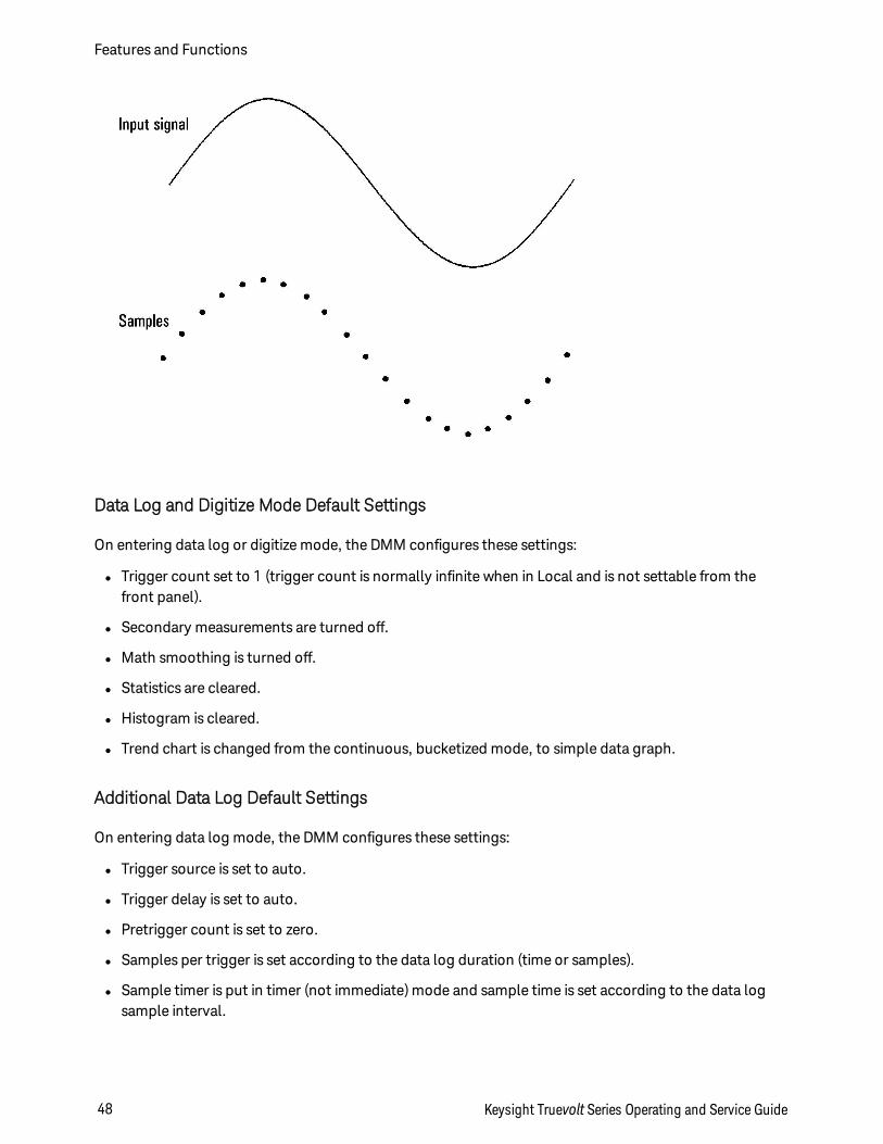
Data Log and Digitize Mode Default Settings
On entering data log or digitize mode, the DMM configures these settings:
l Trigger count set to 1 (trigger count is normally infinite when in Local and is not settable from thefront panel).
l Secondary measurements are turned off.
l Math smoothing is turned off.
l Statistics are cleared.
l Histogram is cleared.
l Trend chart is changed from the continuous, bucketized mode, to simple data graph.
Additional Data Log Default Settings
On entering data log mode, the DMM configures these settings:
l Trigger source is set to auto.
l Trigger delay is set to auto.
l Pretrigger count is set to zero.
l Samples per trigger is set according to the data log duration (time or samples).
l Sample timer is put in timer (not immediate) mode and sample time is set according to the data logsample interval.
Features and Functions
48 Keysight Truevolt Series Operating and Service Guide
Additional Digitize Default Settings
On entering digitize mode, the DMM configures these settings:
l If trigger source is set to manual it is changed to auto. (external and level remain as is.)
l Limits mode is turned off.
l Scaling is turned off.
l Statistic and histogram are put in post-processing mode (computed after digitize is complete).
l On the selected function (DCV or DCI) and for the new function if changed:
l Autorange is turned off.
l Autozero is turned off.
l NPLC and aperture are set to their minimum values.
l If trigger source is external or level, the pretrigger count is set to the digitize pretrigger count setting(default of 0).
l Samples per trigger is set according to the digitize duration (time or samples).
l Sample timer is put in timer (not immediate) mode and Sample timer is set according to the digitizesample rate or sample interval.
l Trend Chart mode is changed to bucketized when data logging to a file.
l On return to Continuous mode, settings are left as done in data log or digitize mode except:
l Sample source is set to immediate.
l Pretrigger count is set to 0.
l Samples per trigger is set to 1.
l Trigger count is set to infinite.
Keysight Truevolt Series Operating and Service Guide 49
Features and Functions
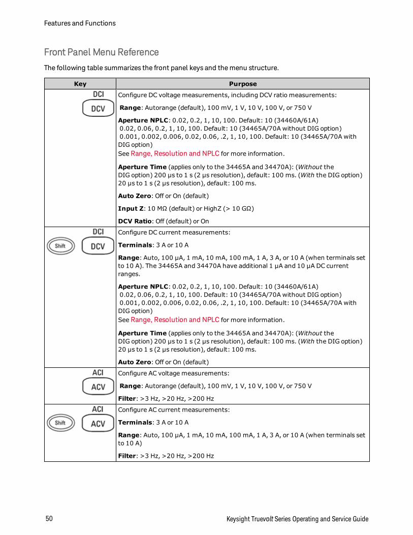
Front Panel Menu Reference
The following table summarizes the front panel keys and the menu structure.
Key Purpose
Configure DC voltage measurements, including DCV ratio measurements:
Range: Autorange (default), 100 mV, 1 V, 10 V, 100 V, or 750 V
Aperture NPLC: 0.02, 0.2, 1, 10, 100. Default: 10 (34460A/61A)0.02, 0.06, 0.2, 1, 10, 100. Default: 10 (34465A/70A without DIG option)0.001, 0.002, 0.006, 0.02, 0.06, .2, 1, 10, 100. Default: 10 (34465A/70A withDIG option)See Range, Resolution and NPLC for more information.
Aperture Time (applies only to the 34465A and 34470A): (Without theDIG option) 200 µs to 1 s (2 µs resolution), default: 100 ms. (With the DIG option)20 µs to 1 s (2 µs resolution), default: 100 ms.
Auto Zero: Off or On (default)
Input Z: 10 MΩ (default) or HighZ (> 10 GΩ)
DCV Ratio: Off (default) or On
Configure DC current measurements:
Terminals: 3 A or 10 A
Range: Auto, 100 µA, 1 mA, 10 mA, 100 mA, 1 A, 3 A, or 10 A (when terminals setto 10 A). The 34465A and 34470A have additional 1 µA and 10 µA DC currentranges.
Aperture NPLC: 0.02, 0.2, 1, 10, 100. Default: 10 (34460A/61A)0.02, 0.06, 0.2, 1, 10, 100. Default: 10 (34465A/70A without DIG option)0.001, 0.002, 0.006, 0.02, 0.06, .2, 1, 10, 100. Default: 10 (34465A/70A withDIG option)See Range, Resolution and NPLC for more information.
Aperture Time (applies only to the 34465A and 34470A): (Without theDIG option) 200 µs to 1 s (2 µs resolution), default: 100 ms. (With the DIG option)20 µs to 1 s (2 µs resolution), default: 100 ms.
Auto Zero: Off or On (default)
Configure AC voltage measurements:
Range: Autorange (default), 100 mV, 1 V, 10 V, 100 V, or 750 V
Filter: >3 Hz, >20 Hz, >200 Hz
Configure AC current measurements:
Terminals: 3 A or 10 A
Range: Auto, 100 µA, 1 mA, 10 mA, 100 mA, 1 A, 3 A, or 10 A (when terminals setto 10 A)
Filter: >3 Hz, >20 Hz, >200 Hz
Features and Functions
50 Keysight Truevolt Series Operating and Service Guide
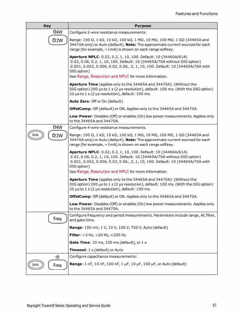
Key Purpose
Configure 2-wire resistance measurements:
Range: 100 Ω, 1 kΩ, 10 kΩ, 100 kΩ, 1 MΩ, 10 MΩ, 100 MΩ, 1 GΩ (34465A and34470A only) or Auto (default).Note: The approximate current sourced for eachrange (for example, ~1mA) is shown on each range softkey.
Aperture NPLC: 0.02, 0.2, 1, 10, 100. Default: 10 (34460A/61A)0.02, 0.06, 0.2, 1, 10, 100. Default: 10 (34465A/70A without DIG option)0.001, 0.002, 0.006, 0.02, 0.06, .2, 1, 10, 100. Default: 10 (34465A/70A withDIG option)See Range, Resolution and NPLC for more information.
Aperture Time (applies only to the 34465A and 34470A): (Without theDIG option) 200 µs to 1 s (2 µs resolution), default: 100 ms. (With the DIG option)20 µs to 1 s (2 µs resolution), default: 100 ms.
Auto Zero: Off or On (default)
OffstComp: Off (default) or ON. Applies only to the 34465A and 34470A.
Low Power: Disables (Off) or enables (On) low power measurements. Applies onlyto the 34465A and 34470A.
Configure 4-wire resistance measurements.
Range: 100 Ω, 1 kΩ, 10 kΩ, 100 kΩ, 1 MΩ, 10 MΩ, 100 MΩ, 1 GΩ (34465A and34470A only) or Auto (default).Note: The approximate current sourced for eachrange (for example, ~1mA) is shown on each range softkey.
Aperture NPLC: 0.02, 0.2, 1, 10, 100. Default: 10 (34460A/61A)0.02, 0.06, 0.2, 1, 10, 100. Default: 10 (34465A/70A without DIG option)0.001, 0.002, 0.006, 0.02, 0.06, .2, 1, 10, 100. Default: 10 (34465A/70A withDIG option)See Range, Resolution and NPLC for more information.
Aperture Time (applies only to the 34465A and 34470A): (Without theDIG option) 200 µs to 1 s (2 µs resolution), default: 100 ms. (With the DIG option)20 µs to 1 s (2 µs resolution), default: 100 ms.
OffstComp: Off (default) or ON. Applies only to the 34465A and 34470A.
Low Power: Disables (Off) or enables (On) low power measurements. Applies onlyto the 34465A and 34470A.
Configure frequency and period measurements. Parameters include range, AC filter,and gate time.
Range: 100 mV, 1 V, 10 V, 100 V, 750 V, Auto (default)
Filter: >3 Hz, >20 Hz, >200 Hz
Gate Time: 10 ms, 100 ms (default), or 1 s
Timeout: 1 s (default) or Auto
Configure capacitance measurements:
Range: 1 nF, 10 nF, 100 nF, 1 µF, 10 µF, 100 µF, or Auto (default)
Keysight Truevolt Series Operating and Service Guide 51
Features and Functions
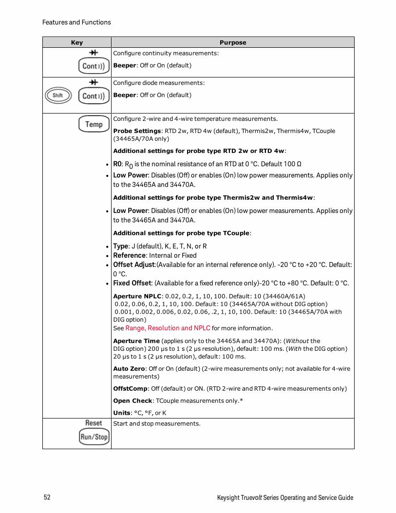
Key Purpose
Configure continuity measurements:
Beeper: Off or On (default)
Configure diode measurements:
Beeper: Off or On (default)
Configure 2-wire and 4-wire temperature measurements.
Probe Settings: RTD 2w, RTD 4w (default), Thermis2w, Thermis4w, TCouple(34465A/70A only)
Additional settings for probe type RTD 2w or RTD 4w:
l R0: R0 is the nominal resistance of an RTD at 0 °C. Default 100 Ω
l Low Power: Disables (Off) or enables (On) low power measurements. Applies onlyto the 34465A and 34470A.
Additional settings for probe type Thermis2w and Thermis4w:
l Low Power: Disables (Off) or enables (On) low power measurements. Applies onlyto the 34465A and 34470A.
Additional settings for probe type TCouple:
l Type: J (default), K, E, T, N, or Rl Reference: Internal or Fixedl Offset Adjust:(Available for an internal reference only). -20 °C to +20 °C. Default:
0 °C.l Fixed Offset: (Available for a fixed reference only)-20 °C to +80 °C. Default: 0 °C.
Aperture NPLC: 0.02, 0.2, 1, 10, 100. Default: 10 (34460A/61A)0.02, 0.06, 0.2, 1, 10, 100. Default: 10 (34465A/70A without DIG option)0.001, 0.002, 0.006, 0.02, 0.06, .2, 1, 10, 100. Default: 10 (34465A/70A withDIG option)See Range, Resolution and NPLC for more information.
Aperture Time (applies only to the 34465A and 34470A): (Without theDIG option) 200 µs to 1 s (2 µs resolution), default: 100 ms. (With the DIG option)20 µs to 1 s (2 µs resolution), default: 100 ms.
Auto Zero: Off or On (default) (2-wire measurements only; not available for 4-wiremeasurements)
OffstComp: Off (default) or ON. (RTD 2-wire and RTD 4-wire measurements only)
Open Check: TCouple measurements only.*
Units: °C, °F, or K
Start and stop measurements.
Features and Functions
52 Keysight Truevolt Series Operating and Service Guide
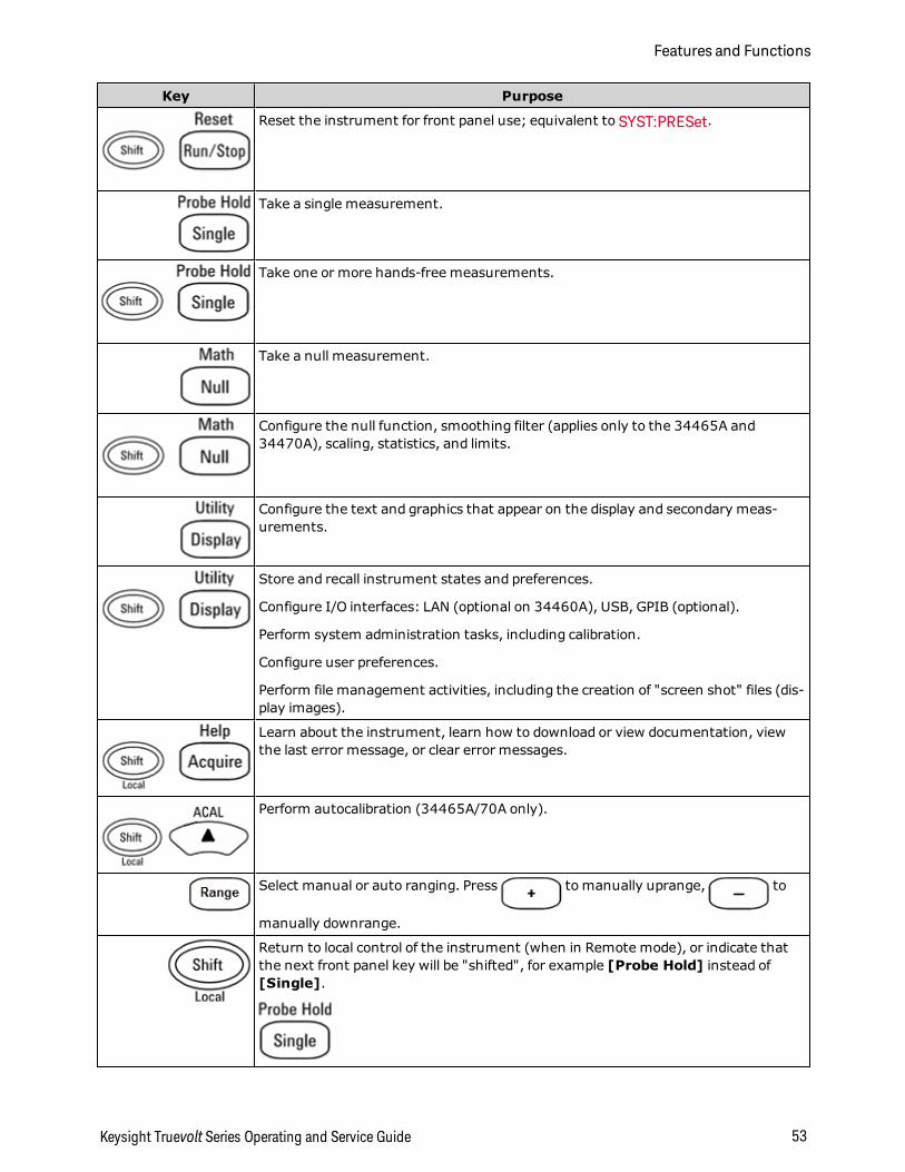
Key Purpose
Reset the instrument for front panel use; equivalent to SYST:PRESet.
Take a single measurement.
Take one or more hands-free measurements.
Take a null measurement.
Configure the null function, smoothing filter (applies only to the 34465A and34470A), scaling, statistics, and limits.
Configure the text and graphics that appear on the display and secondary meas-urements.
Store and recall instrument states and preferences.
Configure I/O interfaces: LAN (optional on 34460A), USB, GPIB (optional).
Perform system administration tasks, including calibration.
Configure user preferences.
Perform file management activities, including the creation of "screen shot" files (dis-play images).
Learn about the instrument, learn how to download or view documentation, viewthe last error message, or clear error messages.
Perform autocalibration (34465A/70A only).
Select manual or auto ranging. Press to manually uprange, to
manually downrange.
Return to local control of the instrument (when in Remote mode), or indicate thatthe next front panel key will be "shifted", for example [Probe Hold] instead of[Single].
Keysight Truevolt Series Operating and Service Guide 53
Features and Functions

The keys that access a wide range of functions are listed below.
[Acquire] key
Softkey Description
Acquire Select Continuous mode (default measurement mode), Digitize mode, or Data Logmode.*
Trigger Set-tings
Configure triggering.
VMC Out Set slope of VM Comp output.
Save Readings Save readings to a file.
* Digitize and Data Log modes are available only on the 34465A/70A. The Digitizemode requires the DIGoption.
[Math] key
The availability of the Math softkeys varies by measurement function.
Softkey Description
Null Enable/disable use of null values and specify null value to use.
SmoothingFilter
(34465A/70A only) Smoothing uses a moving average (boxcar) filter to reduce random noisein measurements. Smoothing is intended to average out small variations in the meas-urements. Larger variations will cause the filter to reset.
dB / dBm (34460A/61A only) Configure dB, dBm
Scaling (34465A/70A only) Configure scaling: dB, dBm, %, Mx-B
Statistics Enable, disable, and clear statistics.
Limits Enable or disable high and low limits.
[Display] key
Features and Functions
54 Keysight Truevolt Series Operating and Service Guide
Softkey Description
Display Choose what is displayed: number, bar meter, histogram, or trend chart (34461A/65A/70Aonly).
Label Enable or disable the display of a message.
LabelText
Edit the text displayed when the Label softkey is On.
2nd Meas Select a secondary measurement.
DigitMask
Set the number of digits displayed for measurements.
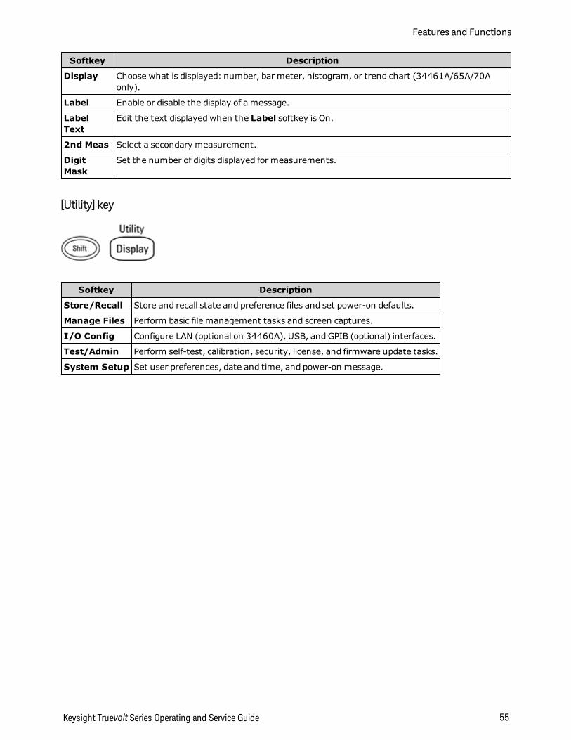
[Utility] key
Softkey Description
Store/Recall Store and recall state and preference files and set power-on defaults.
Manage Files Perform basic file management tasks and screen captures.
I/O Config Configure LAN (optional on 34460A), USB, and GPIB (optional) interfaces.
Test/Admin Perform self-test, calibration, security, license, and firmware update tasks.
System Setup Set user preferences, date and time, and power-on message.
Keysight Truevolt Series Operating and Service Guide 55
Features and Functions
Measurements
The Keysight Truevolt DMMs support many common measurements:
DC Voltage
AC Voltage
DC Current
AC Current
Resistance
Temperature
Capacitance
Continuity
Diode
Frequency and Period
Data Logging
Digitizing
Level Triggering
Features and Functions
56 Keysight Truevolt Series Operating and Service Guide
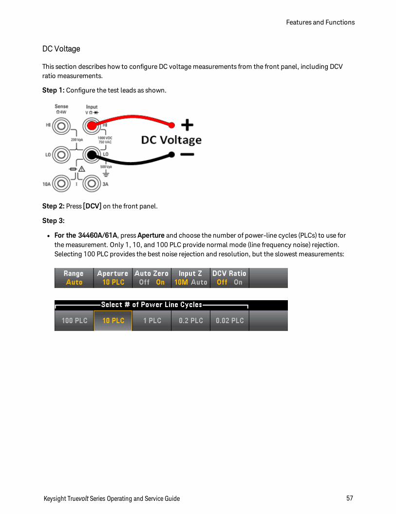
DC Voltage
This section describes how to configure DC voltage measurements from the front panel, including DCVratio measurements.
Step 1: Configure the test leads as shown.
Step 2: Press [DCV] on the front panel.
Step 3:
l For the 34460A/61A, press Aperture and choose the number of power-line cycles (PLCs) to use forthe measurement. Only 1, 10, and 100 PLC provide normal mode (line frequency noise) rejection.Selecting 100 PLC provides the best noise rejection and resolution, but the slowest measurements:
Keysight Truevolt Series Operating and Service Guide 57
Features and Functions
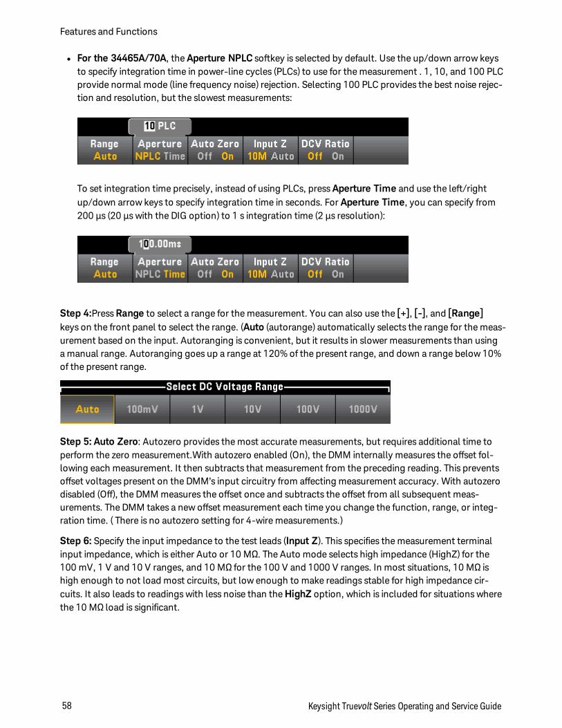
l For the 34465A/70A, the Aperture NPLC softkey is selected by default. Use the up/down arrow keysto specify integration time in power-line cycles (PLCs) to use for the measurement . 1, 10, and 100 PLCprovide normal mode (line frequency noise) rejection. Selecting 100 PLC provides the best noise rejec-tion and resolution, but the slowest measurements:
To set integration time precisely, instead of using PLCs, press Aperture Time and use the left/rightup/down arrow keys to specify integration time in seconds. For Aperture Time, you can specify from200 µs (20 µs with the DIG option) to 1 s integration time (2 µs resolution):
Step 4:Press Range to select a range for the measurement. You can also use the [+], [-], and [Range]keys on the front panel to select the range. (Auto (autorange) automatically selects the range for the meas-urement based on the input. Autoranging is convenient, but it results in slower measurements than usinga manual range. Autoranging goes up a range at 120% of the present range, and down a range below 10%of the present range.
Step 5: Auto Zero: Autozero provides the most accurate measurements, but requires additional time toperform the zero measurement.With autozero enabled (On), the DMM internally measures the offset fol-lowing each measurement. It then subtracts that measurement from the preceding reading. This preventsoffset voltages present on the DMM’s input circuitry from affecting measurement accuracy. With autozerodisabled (Off), the DMM measures the offset once and subtracts the offset from all subsequent meas-urements. The DMM takes a new offset measurement each time you change the function, range, or integ-ration time. ( There is no autozero setting for 4-wire measurements.)
Step 6: Specify the input impedance to the test leads (Input Z). This specifies the measurement terminalinput impedance, which is either Auto or 10 MΩ. The Auto mode selects high impedance (HighZ) for the100 mV, 1 V and 10 V ranges, and 10 MΩ for the 100 V and 1000 V ranges. In most situations, 10 MΩ ishigh enough to not load most circuits, but low enough to make readings stable for high impedance cir-cuits. It also leads to readings with less noise than the HighZ option, which is included for situations wherethe 10 MΩ load is significant.
Features and Functions
58 Keysight Truevolt Series Operating and Service Guide
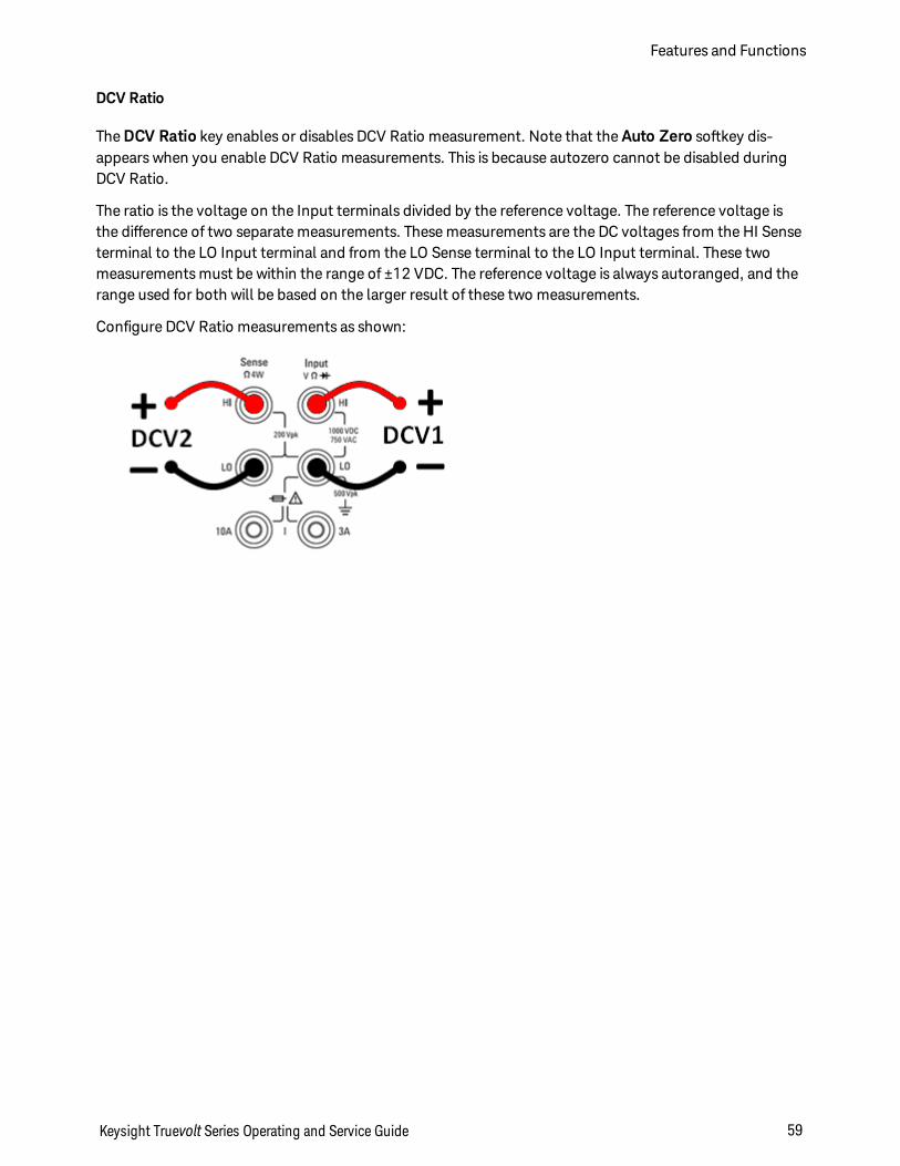
DCV Ratio
The DCV Ratio key enables or disables DCV Ratio measurement. Note that the Auto Zero softkey dis-appears when you enable DCV Ratio measurements. This is because autozero cannot be disabled duringDCV Ratio.
The ratio is the voltage on the Input terminals divided by the reference voltage. The reference voltage isthe difference of two separate measurements. These measurements are the DC voltages from the HI Senseterminal to the LO Input terminal and from the LO Sense terminal to the LO Input terminal. These twomeasurements must be within the range of ±12 VDC. The reference voltage is always autoranged, and therange used for both will be based on the larger result of these two measurements.
Configure DCV Ratio measurements as shown:
Keysight Truevolt Series Operating and Service Guide 59
Features and Functions
AC Voltage
This section describes how to configure AC voltage measurements from the front panel.
Default delays are selected to give correct first readings for most measurements. For the mostaccurate measurements, the input blocking RC time constant must settle to 1/50 of the ACsignal level.
Signals greater than 300 V (rms) or 1 A (rms) will cause self-heating in signal-conditioningcomponents. These errors are included in the instrument specifications. Internal temperaturechanges due to self-heating may cause additional error on other functions or ranges. The addi-tional error will generally dissipate within a few minutes.
For example, consider a 100 mVAC signal with a 10 VDC bias. The 10 VDC bias should besettled to 1/50 of 100 mVAC, or 2 mVDC. The corresponding settling time can be calculatedusing the blocking RC time constant of 0.22 s as follows:
settling time = ln(bias/settled value) * 0.22 s
settling time = ln(10 VDC / 2 mVDC) * 0.22 s
settling time = ln(5000) * 0.22 s = 1.9 s
This additional settling delay should be applied after connecting the signal to the DMM's ACVinput or after selecting the ACV function with the signal already connected. If the DC biasremains constant, subsequent measurements can be made to full accuracy without additionalsettling delays.
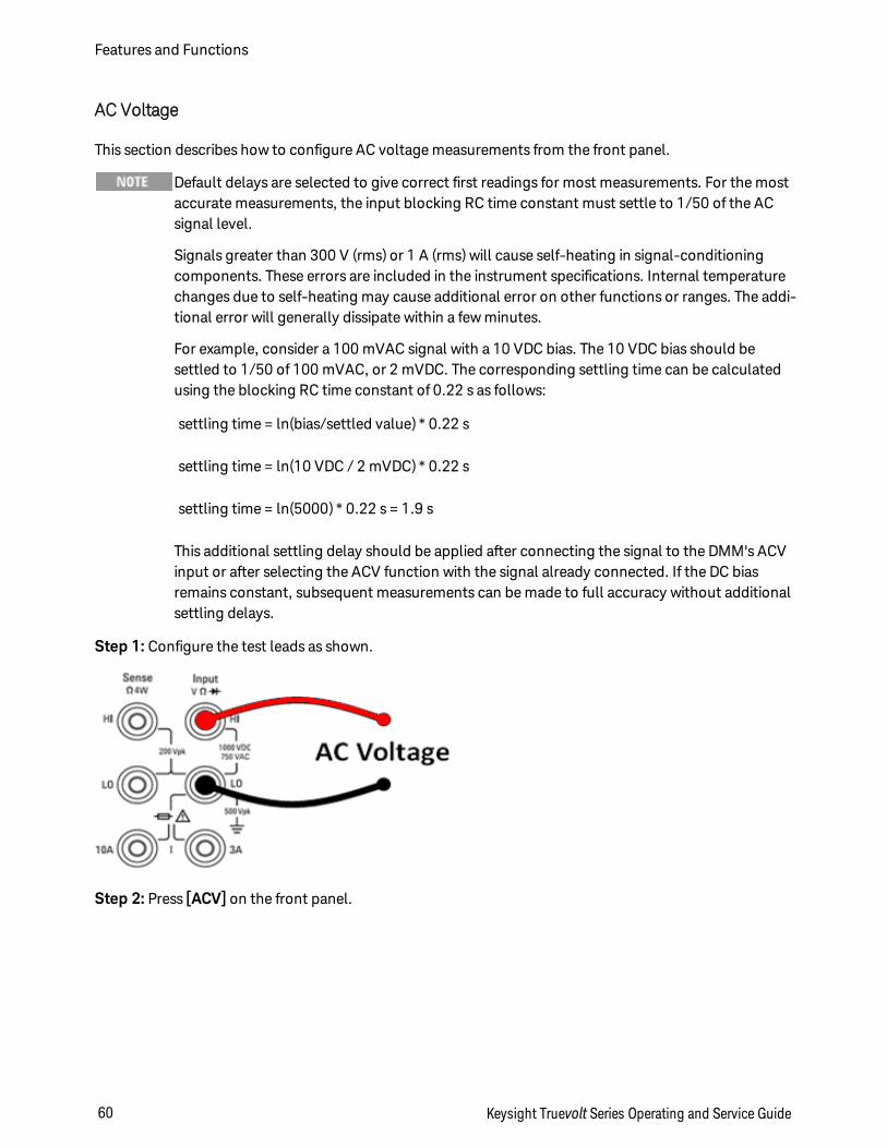
Step 1: Configure the test leads as shown.
Step 2: Press [ACV] on the front panel.
Features and Functions
60 Keysight Truevolt Series Operating and Service Guide
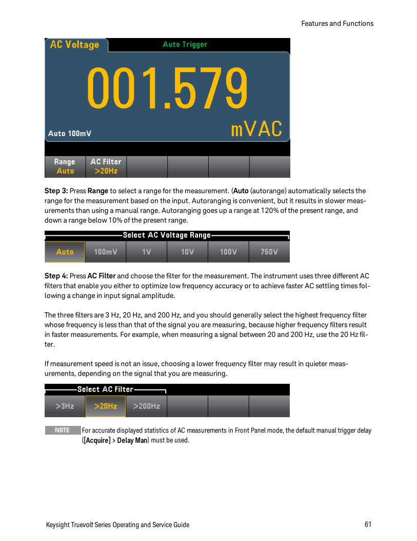
Step 3: Press Range to select a range for the measurement. (Auto (autorange) automatically selects therange for the measurement based on the input. Autoranging is convenient, but it results in slower meas-urements than using a manual range. Autoranging goes up a range at 120% of the present range, anddown a range below 10% of the present range.
Step 4: Press AC Filter and choose the filter for the measurement. The instrument uses three different ACfilters that enable you either to optimize low frequency accuracy or to achieve faster AC settling times fol-lowing a change in input signal amplitude.
The three filters are 3 Hz, 20 Hz, and 200 Hz, and you should generally select the highest frequency filterwhose frequency is less than that of the signal you are measuring, because higher frequency filters resultin faster measurements. For example, when measuring a signal between 20 and 200 Hz, use the 20 Hz fil-ter.
If measurement speed is not an issue, choosing a lower frequency filter may result in quieter meas-urements, depending on the signal that you are measuring.
For accurate displayed statistics of AC measurements in Front Panel mode, the default manual trigger delay([Acquire] > Delay Man) must be used.
Keysight Truevolt Series Operating and Service Guide 61
Features and Functions
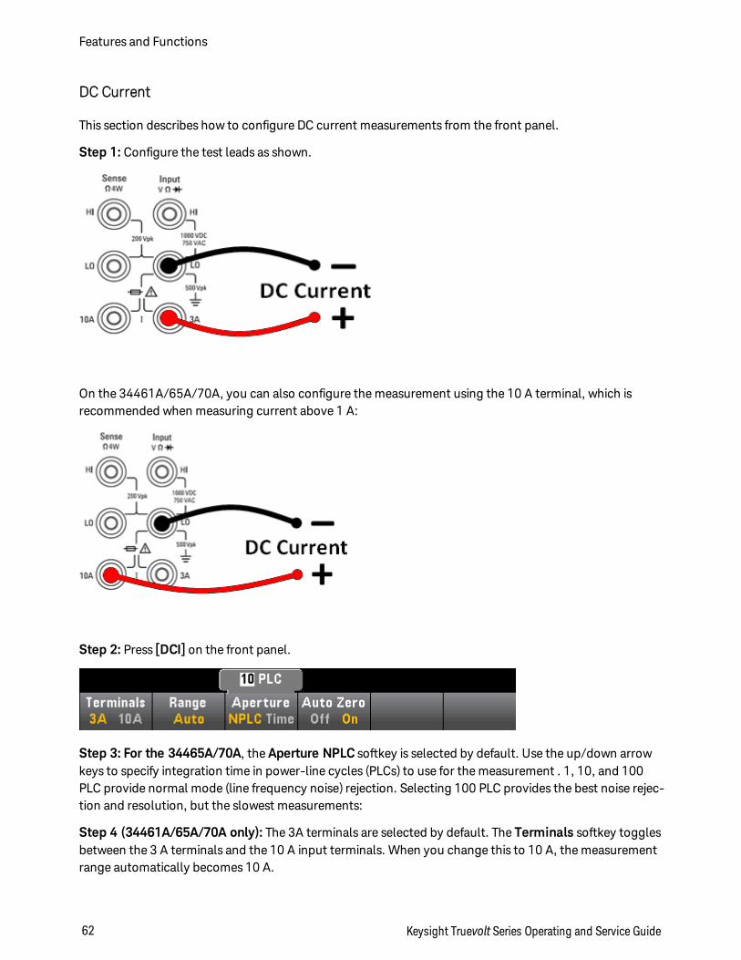
DC Current
This section describes how to configure DC current measurements from the front panel.
Step 1: Configure the test leads as shown.
On the 34461A/65A/70A, you can also configure the measurement using the 10 A terminal, which isrecommended when measuring current above 1 A:
Step 2: Press [DCI] on the front panel.
Step 3: For the 34465A/70A, the Aperture NPLC softkey is selected by default. Use the up/down arrowkeys to specify integration time in power-line cycles (PLCs) to use for the measurement . 1, 10, and 100PLC provide normal mode (line frequency noise) rejection. Selecting 100 PLC provides the best noise rejec-tion and resolution, but the slowest measurements:
Step 4 (34461A/65A/70A only): The 3A terminals are selected by default. The Terminals softkey togglesbetween the 3 A terminals and the 10 A input terminals. When you change this to 10 A, the measurementrange automatically becomes 10 A.
Features and Functions
62 Keysight Truevolt Series Operating and Service Guide
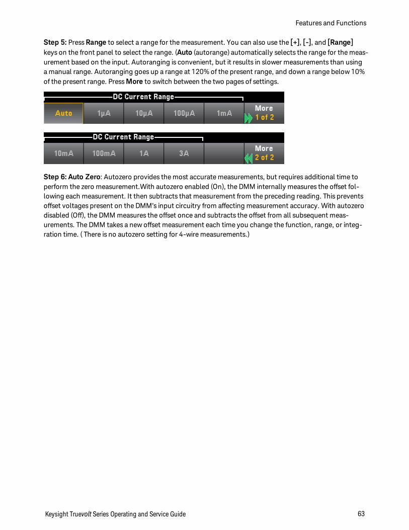
Step 5: Press Range to select a range for the measurement. You can also use the [+], [-], and [Range]keys on the front panel to select the range. (Auto (autorange) automatically selects the range for the meas-urement based on the input. Autoranging is convenient, but it results in slower measurements than usinga manual range. Autoranging goes up a range at 120% of the present range, and down a range below 10%of the present range. Press More to switch between the two pages of settings.
Step 6: Auto Zero: Autozero provides the most accurate measurements, but requires additional time toperform the zero measurement.With autozero enabled (On), the DMM internally measures the offset fol-lowing each measurement. It then subtracts that measurement from the preceding reading. This preventsoffset voltages present on the DMM’s input circuitry from affecting measurement accuracy. With autozerodisabled (Off), the DMM measures the offset once and subtracts the offset from all subsequent meas-urements. The DMM takes a new offset measurement each time you change the function, range, or integ-ration time. ( There is no autozero setting for 4-wire measurements.)
Keysight Truevolt Series Operating and Service Guide 63
Features and Functions
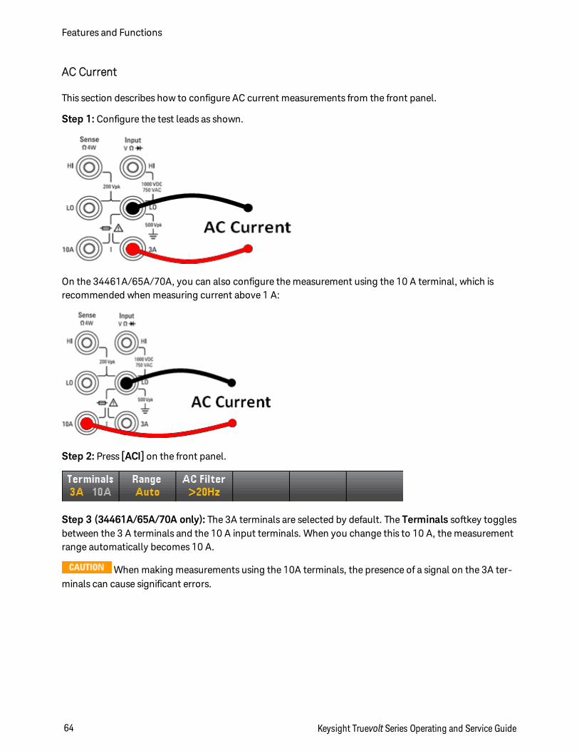
AC Current
This section describes how to configure AC current measurements from the front panel.
Step 1: Configure the test leads as shown.
On the 34461A/65A/70A, you can also configure the measurement using the 10 A terminal, which isrecommended when measuring current above 1 A:
Step 2: Press [ACI] on the front panel.
Step 3 (34461A/65A/70A only): The 3A terminals are selected by default. The Terminals softkey togglesbetween the 3 A terminals and the 10 A input terminals. When you change this to 10 A, the measurementrange automatically becomes 10 A.
When making measurements using the 10A terminals, the presence of a signal on the 3A ter-minals can cause significant errors.
Features and Functions
64 Keysight Truevolt Series Operating and Service Guide
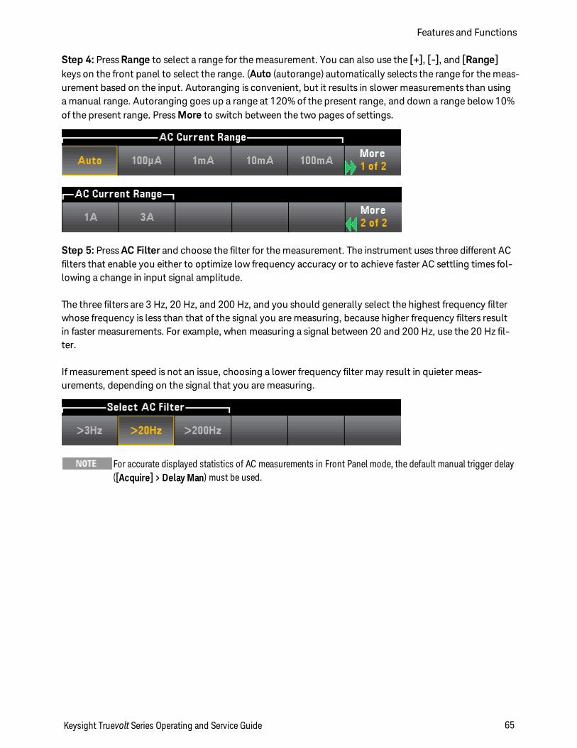
Step 4: Press Range to select a range for the measurement. You can also use the [+], [-], and [Range]keys on the front panel to select the range. (Auto (autorange) automatically selects the range for the meas-urement based on the input. Autoranging is convenient, but it results in slower measurements than usinga manual range. Autoranging goes up a range at 120% of the present range, and down a range below 10%of the present range. Press More to switch between the two pages of settings.
Step 5: Press AC Filter and choose the filter for the measurement. The instrument uses three different ACfilters that enable you either to optimize low frequency accuracy or to achieve faster AC settling times fol-lowing a change in input signal amplitude.
The three filters are 3 Hz, 20 Hz, and 200 Hz, and you should generally select the highest frequency filterwhose frequency is less than that of the signal you are measuring, because higher frequency filters resultin faster measurements. For example, when measuring a signal between 20 and 200 Hz, use the 20 Hz fil-ter.
If measurement speed is not an issue, choosing a lower frequency filter may result in quieter meas-urements, depending on the signal that you are measuring.
For accurate displayed statistics of AC measurements in Front Panel mode, the default manual trigger delay([Acquire] > Delay Man) must be used.
Keysight Truevolt Series Operating and Service Guide 65
Features and Functions
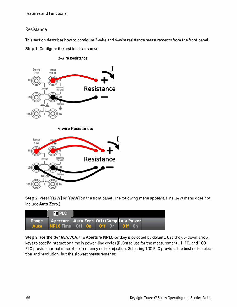
Resistance
This section describes how to configure 2-wire and 4-wire resistance measurements from the front panel.
Step 1: Configure the test leads as shown.
2-wire Resistance:
4-wire Resistance:
Step 2: Press [Ω2W] or [Ω4W] on the front panel. The following menu appears. (The Ω4W menu does notinclude Auto Zero.)
Step 3: For the 34465A/70A, the Aperture NPLC softkey is selected by default. Use the up/down arrowkeys to specify integration time in power-line cycles (PLCs) to use for the measurement . 1, 10, and 100PLC provide normal mode (line frequency noise) rejection. Selecting 100 PLC provides the best noise rejec-tion and resolution, but the slowest measurements:
Features and Functions
66 Keysight Truevolt Series Operating and Service Guide
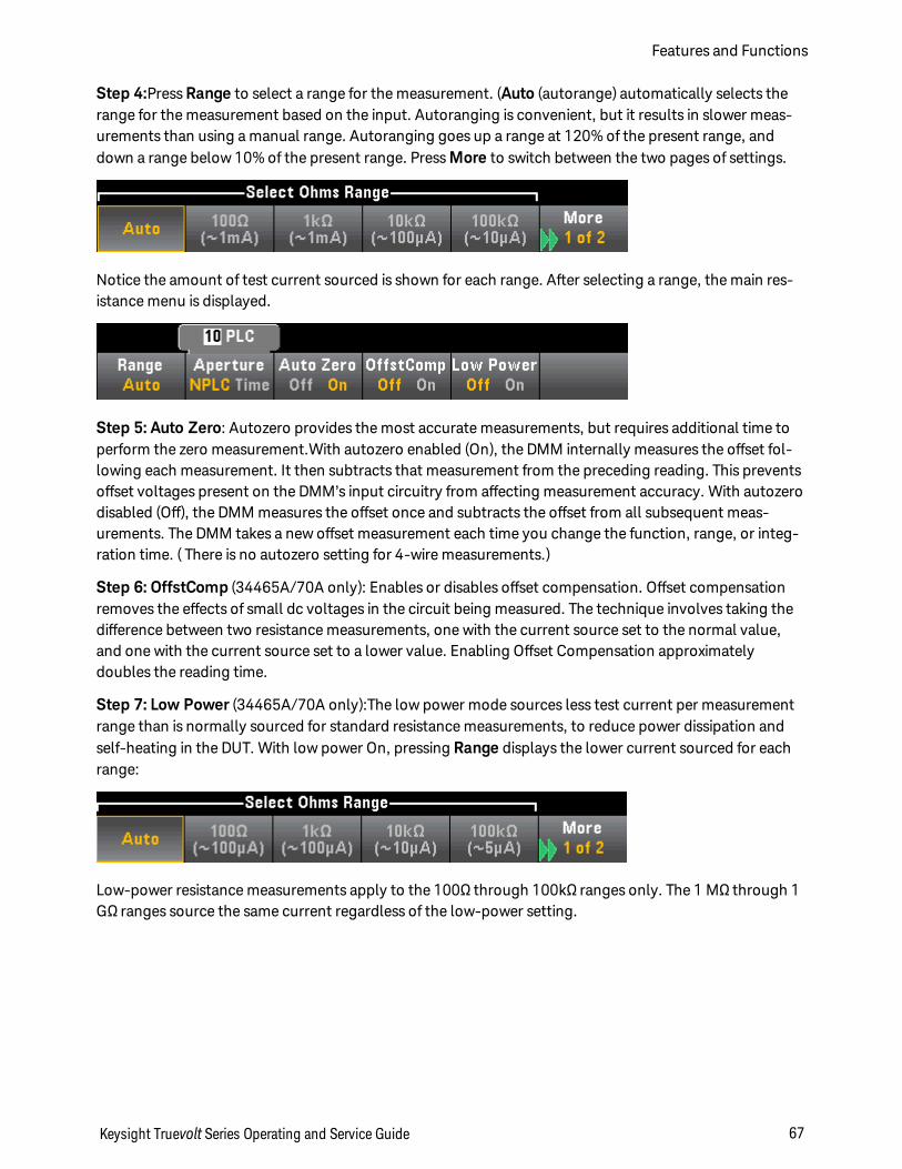
Step 4:Press Range to select a range for the measurement. (Auto (autorange) automatically selects therange for the measurement based on the input. Autoranging is convenient, but it results in slower meas-urements than using a manual range. Autoranging goes up a range at 120% of the present range, anddown a range below 10% of the present range. Press More to switch between the two pages of settings.
Notice the amount of test current sourced is shown for each range. After selecting a range, the main res-istance menu is displayed.
Step 5: Auto Zero: Autozero provides the most accurate measurements, but requires additional time toperform the zero measurement.With autozero enabled (On), the DMM internally measures the offset fol-lowing each measurement. It then subtracts that measurement from the preceding reading. This preventsoffset voltages present on the DMM’s input circuitry from affecting measurement accuracy. With autozerodisabled (Off), the DMM measures the offset once and subtracts the offset from all subsequent meas-urements. The DMM takes a new offset measurement each time you change the function, range, or integ-ration time. ( There is no autozero setting for 4-wire measurements.)
Step 6: OffstComp (34465A/70A only): Enables or disables offset compensation. Offset compensationremoves the effects of small dc voltages in the circuit being measured. The technique involves taking thedifference between two resistance measurements, one with the current source set to the normal value,and one with the current source set to a lower value. Enabling Offset Compensation approximatelydoubles the reading time.
Step 7: Low Power (34465A/70A only):The low power mode sources less test current per measurementrange than is normally sourced for standard resistance measurements, to reduce power dissipation andself-heating in the DUT. With low power On, pressing Range displays the lower current sourced for eachrange:
Low-power resistance measurements apply to the 100Ω through 100kΩ ranges only. The 1 MΩ through 1GΩ ranges source the same current regardless of the low-power setting.
Keysight Truevolt Series Operating and Service Guide 67
Features and Functions
Negative Resistance Measurements
Under certain conditions, the instrument may report negative resistance measurements. These may occurin 2-wire and 4-wire resistance measurements or continuity measurements.
Conditions that may cause negative ohms values include:
l Changes in Front/Rear switch contact resistance
l Reversed Sense Hi and Lo leads
l Circuits with external bias or thermal voltages at circuit connections
l Changes in measurement connection after a NULL operation
Under the same conditions, the 34401A returns the measurement’s absolute value so as to prevent theconfusion associated with negative readings. The Keysight Truevolt Series DMMs will return negative val-ues. This allows the most accurate results after a NULL operation.
Features and Functions
68 Keysight Truevolt Series Operating and Service Guide
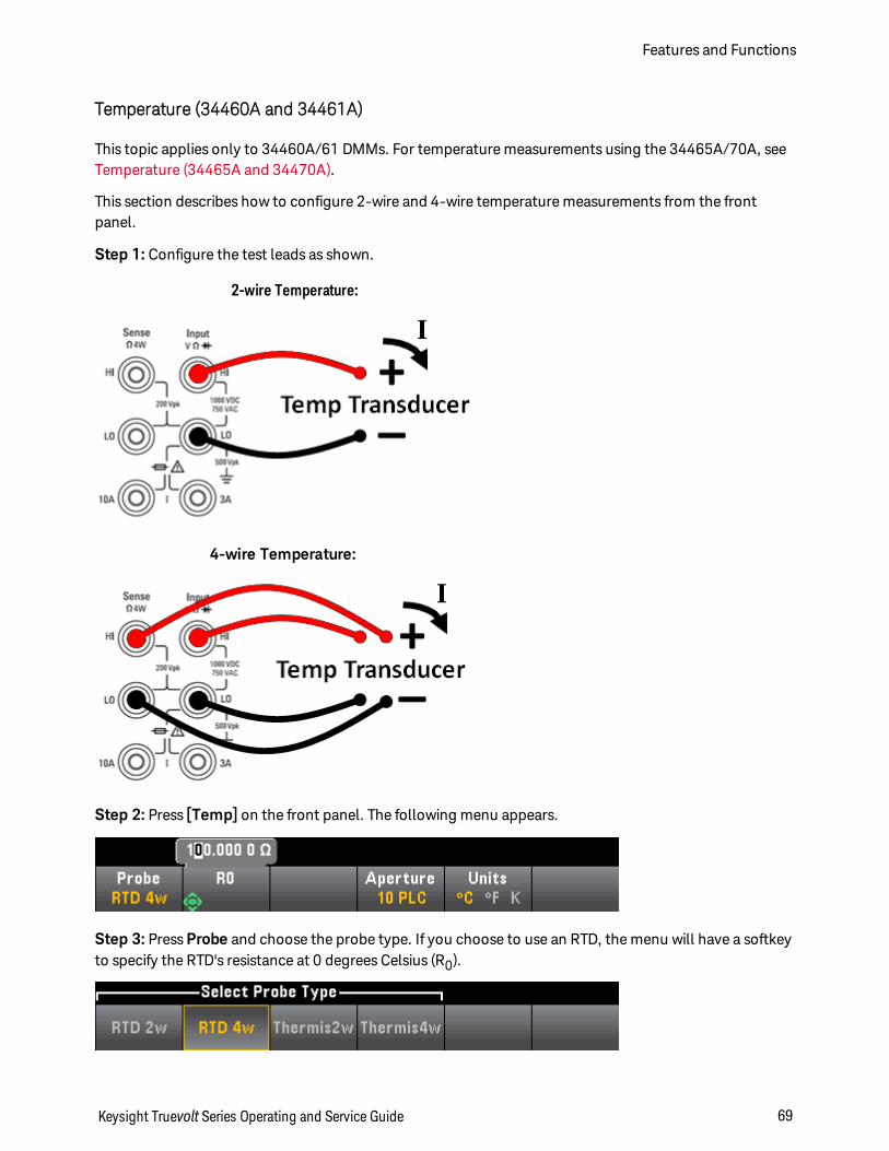
Temperature (34460A and 34461A)
This topic applies only to 34460A/61 DMMs. For temperature measurements using the 34465A/70A, seeTemperature (34465A and 34470A).
This section describes how to configure 2-wire and 4-wire temperature measurements from the frontpanel.
Step 1: Configure the test leads as shown.
2-wire Temperature:
4-wire Temperature:
Step 2: Press [Temp] on the front panel. The following menu appears.
Step 3: Press Probe and choose the probe type. If you choose to use an RTD, the menu will have a softkeyto specify the RTD's resistance at 0 degrees Celsius (R0).
Keysight Truevolt Series Operating and Service Guide 69
Features and Functions
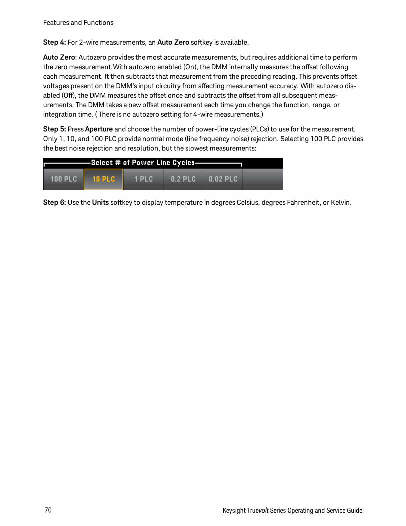
Step 4: For 2-wire measurements, an Auto Zero softkey is available.
Auto Zero: Autozero provides the most accurate measurements, but requires additional time to performthe zero measurement.With autozero enabled (On), the DMM internally measures the offset followingeach measurement. It then subtracts that measurement from the preceding reading. This prevents offsetvoltages present on the DMM’s input circuitry from affecting measurement accuracy. With autozero dis-abled (Off), the DMM measures the offset once and subtracts the offset from all subsequent meas-urements. The DMM takes a new offset measurement each time you change the function, range, orintegration time. ( There is no autozero setting for 4-wire measurements.)
Step 5: Press Aperture and choose the number of power-line cycles (PLCs) to use for the measurement.Only 1, 10, and 100 PLC provide normal mode (line frequency noise) rejection. Selecting 100 PLC providesthe best noise rejection and resolution, but the slowest measurements:
Step 6: Use the Units softkey to display temperature in degrees Celsius, degrees Fahrenheit, or Kelvin.
Features and Functions
70 Keysight Truevolt Series Operating and Service Guide
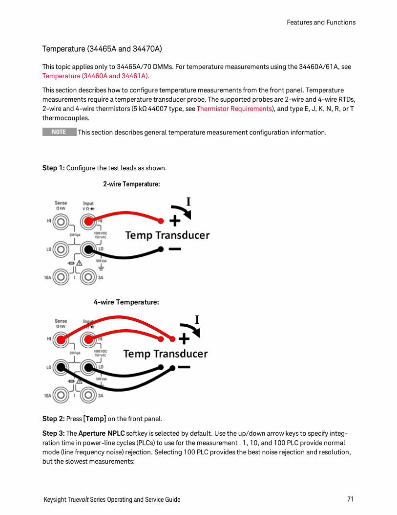
Temperature (34465A and 34470A)
This topic applies only to 34465A/70 DMMs. For temperature measurements using the 34460A/61A, seeTemperature (34460A and 34461A).
This section describes how to configure temperature measurements from the front panel. Temperaturemeasurements require a temperature transducer probe. The supported probes are 2-wire and 4-wire RTDs,2-wire and 4-wire thermistors (5 kΩ 44007 type, see Thermistor Requirements), and type E, J, K, N, R, or Tthermocouples.
This section describes general temperature measurement configuration information.
Step 1: Configure the test leads as shown.
2-wire Temperature:
4-wire Temperature:
Step 2: Press [Temp] on the front panel.
Step 3: The Aperture NPLC softkey is selected by default. Use the up/down arrow keys to specify integ-ration time in power-line cycles (PLCs) to use for the measurement . 1, 10, and 100 PLC provide normalmode (line frequency noise) rejection. Selecting 100 PLC provides the best noise rejection and resolution,but the slowest measurements:
Keysight Truevolt Series Operating and Service Guide 71
Features and Functions
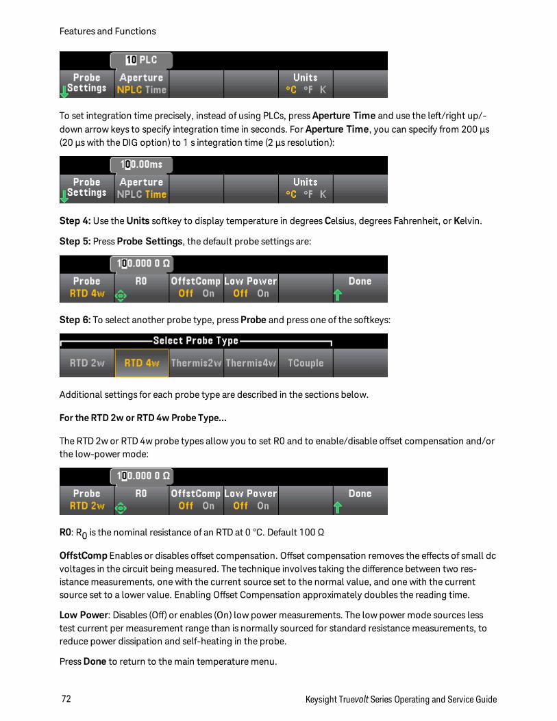
To set integration time precisely, instead of using PLCs, press Aperture Time and use the left/right up/-down arrow keys to specify integration time in seconds. For Aperture Time, you can specify from 200 µs(20 µs with the DIG option) to 1 s integration time (2 µs resolution):
Step 4: Use the Units softkey to display temperature in degrees Celsius, degrees Fahrenheit, or Kelvin.
Step 5: Press Probe Settings, the default probe settings are:
Step 6: To select another probe type, press Probe and press one of the softkeys:
Additional settings for each probe type are described in the sections below.
For the RTD 2w or RTD 4w Probe Type...
The RTD 2w or RTD 4w probe types allow you to set R0 and to enable/disable offset compensation and/orthe low-power mode:
R0: R0 is the nominal resistance of an RTD at 0 °C. Default 100 Ω
OffstComp Enables or disables offset compensation. Offset compensation removes the effects of small dcvoltages in the circuit being measured. The technique involves taking the difference between two res-istance measurements, one with the current source set to the normal value, and one with the currentsource set to a lower value. Enabling Offset Compensation approximately doubles the reading time.
Low Power: Disables (Off) or enables (On) low power measurements. The low power mode sources lesstest current per measurement range than is normally sourced for standard resistance measurements, toreduce power dissipation and self-heating in the probe.
Press Done to return to the main temperature menu.
Features and Functions
72 Keysight Truevolt Series Operating and Service Guide
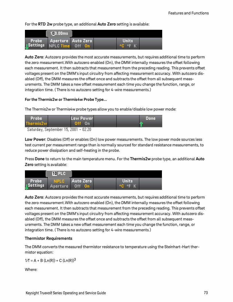
For the RTD 2w probe type, an additional Auto Zero setting is available:
Auto Zero: Autozero provides the most accurate measurements, but requires additional time to performthe zero measurement.With autozero enabled (On), the DMM internally measures the offset followingeach measurement. It then subtracts that measurement from the preceding reading. This prevents offsetvoltages present on the DMM’s input circuitry from affecting measurement accuracy. With autozero dis-abled (Off), the DMM measures the offset once and subtracts the offset from all subsequent meas-urements. The DMM takes a new offset measurement each time you change the function, range, orintegration time. ( There is no autozero setting for 4-wire measurements.)
For the Thermis2w or Thermis4w Probe Type...
The Thermis2w or Thermis4w probe types allow you to enable/disable low power mode:
Low Power: Disables (Off) or enables (On) low power measurements. The low power mode sources lesstest current per measurement range than is normally sourced for standard resistance measurements, toreduce power dissipation and self-heating in the probe.
Press Done to return to the main temperature menu. For the Thermis2w probe type, an additional AutoZero setting is available:
Auto Zero: Autozero provides the most accurate measurements, but requires additional time to performthe zero measurement.With autozero enabled (On), the DMM internally measures the offset followingeach measurement. It then subtracts that measurement from the preceding reading. This prevents offsetvoltages present on the DMM’s input circuitry from affecting measurement accuracy. With autozero dis-abled (Off), the DMM measures the offset once and subtracts the offset from all subsequent meas-urements. The DMM takes a new offset measurement each time you change the function, range, orintegration time. ( There is no autozero setting for 4-wire measurements.)
Thermistor Requirements
The DMM converts the measured thermistor resistance to temperature using the Steinhart-Hart ther-mistor equation:
1⁄T = A + B (Ln(R)) + C (Ln(R))3
Where:
Keysight Truevolt Series Operating and Service Guide 73
Features and Functions
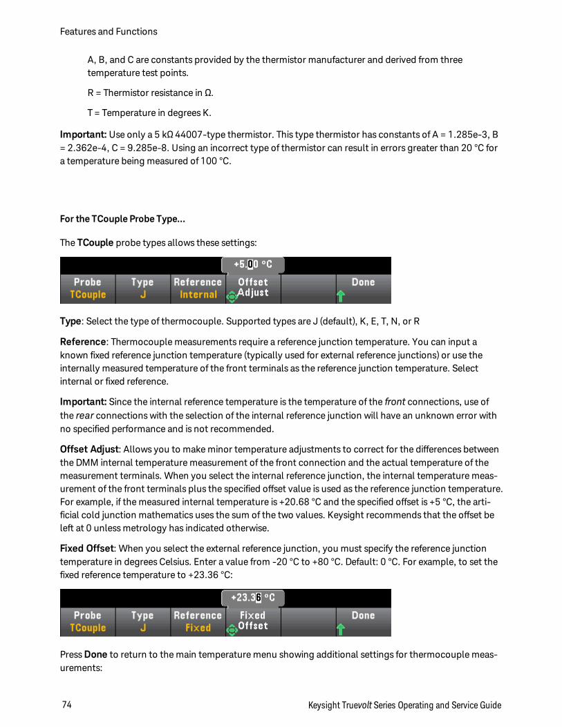
A, B, and C are constants provided by the thermistor manufacturer and derived from threetemperature test points.
R = Thermistor resistance in Ω.
T = Temperature in degrees K.
Important: Use only a 5 kΩ 44007-type thermistor. This type thermistor has constants of A = 1.285e-3, B= 2.362e-4, C = 9.285e-8. Using an incorrect type of thermistor can result in errors greater than 20 °C fora temperature being measured of 100 °C.
For the TCouple Probe Type...
The TCouple probe types allows these settings:
Type: Select the type of thermocouple. Supported types are J (default), K, E, T, N, or R
Reference: Thermocouple measurements require a reference junction temperature. You can input aknown fixed reference junction temperature (typically used for external reference junctions) or use theinternally measured temperature of the front terminals as the reference junction temperature. Selectinternal or fixed reference.
Important: Since the internal reference temperature is the temperature of the front connections, use ofthe rear connections with the selection of the internal reference junction will have an unknown error withno specified performance and is not recommended.
Offset Adjust: Allows you to make minor temperature adjustments to correct for the differences betweenthe DMM internal temperature measurement of the front connection and the actual temperature of themeasurement terminals. When you select the internal reference junction, the internal temperature meas-urement of the front terminals plus the specified offset value is used as the reference junction temperature.For example, if the measured internal temperature is +20.68 °C and the specified offset is +5 °C, the arti-ficial cold junction mathematics uses the sum of the two values. Keysight recommends that the offset beleft at 0 unless metrology has indicated otherwise.
Fixed Offset: When you select the external reference junction, you must specify the reference junctiontemperature in degrees Celsius. Enter a value from -20 °C to +80 °C. Default: 0 °C. For example, to set thefixed reference temperature to +23.36 °C:
Press Done to return to the main temperature menu showing additional settings for thermocouple meas-urements:
Features and Functions
74 Keysight Truevolt Series Operating and Service Guide
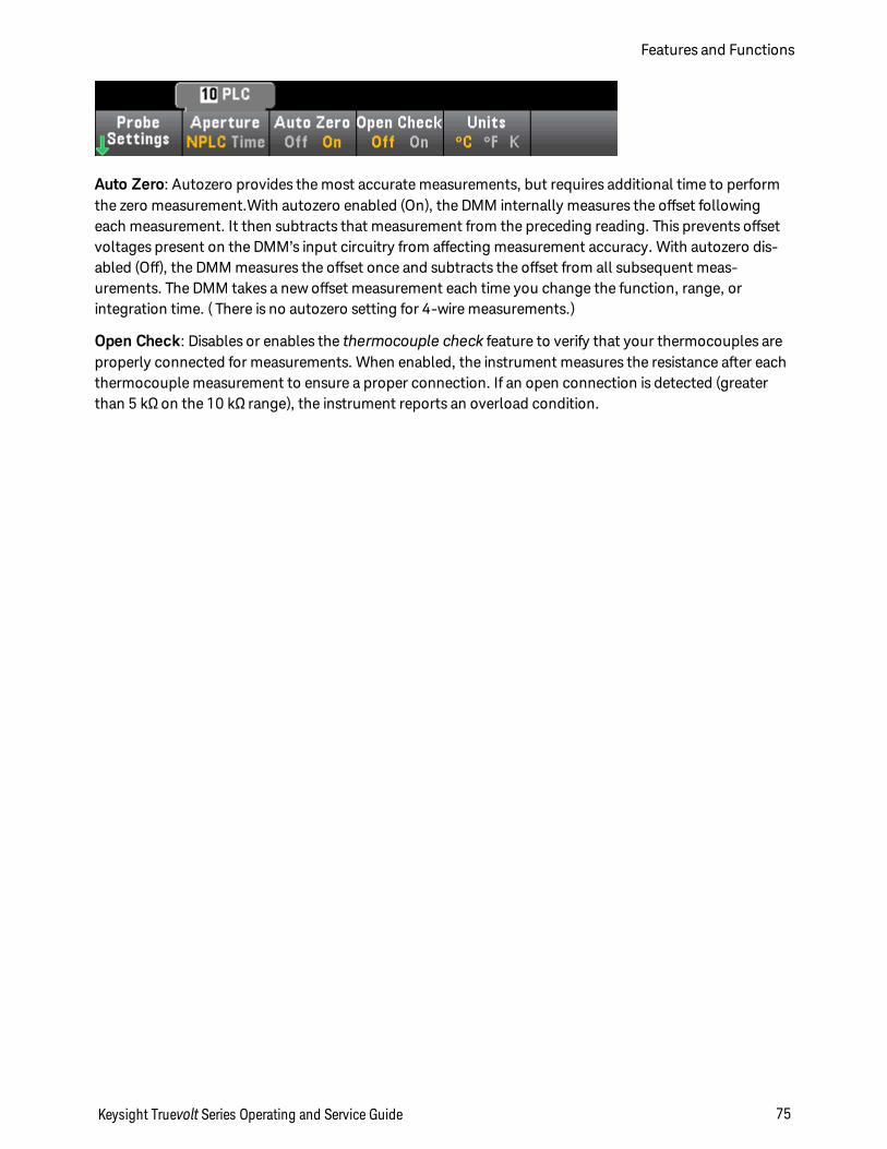
Auto Zero: Autozero provides the most accurate measurements, but requires additional time to performthe zero measurement.With autozero enabled (On), the DMM internally measures the offset followingeach measurement. It then subtracts that measurement from the preceding reading. This prevents offsetvoltages present on the DMM’s input circuitry from affecting measurement accuracy. With autozero dis-abled (Off), the DMM measures the offset once and subtracts the offset from all subsequent meas-urements. The DMM takes a new offset measurement each time you change the function, range, orintegration time. ( There is no autozero setting for 4-wire measurements.)
Open Check: Disables or enables the thermocouple check feature to verify that your thermocouples areproperly connected for measurements. When enabled, the instrument measures the resistance after eachthermocouple measurement to ensure a proper connection. If an open connection is detected (greaterthan 5 kΩ on the 10 kΩ range), the instrument reports an overload condition.
Keysight Truevolt Series Operating and Service Guide 75
Features and Functions
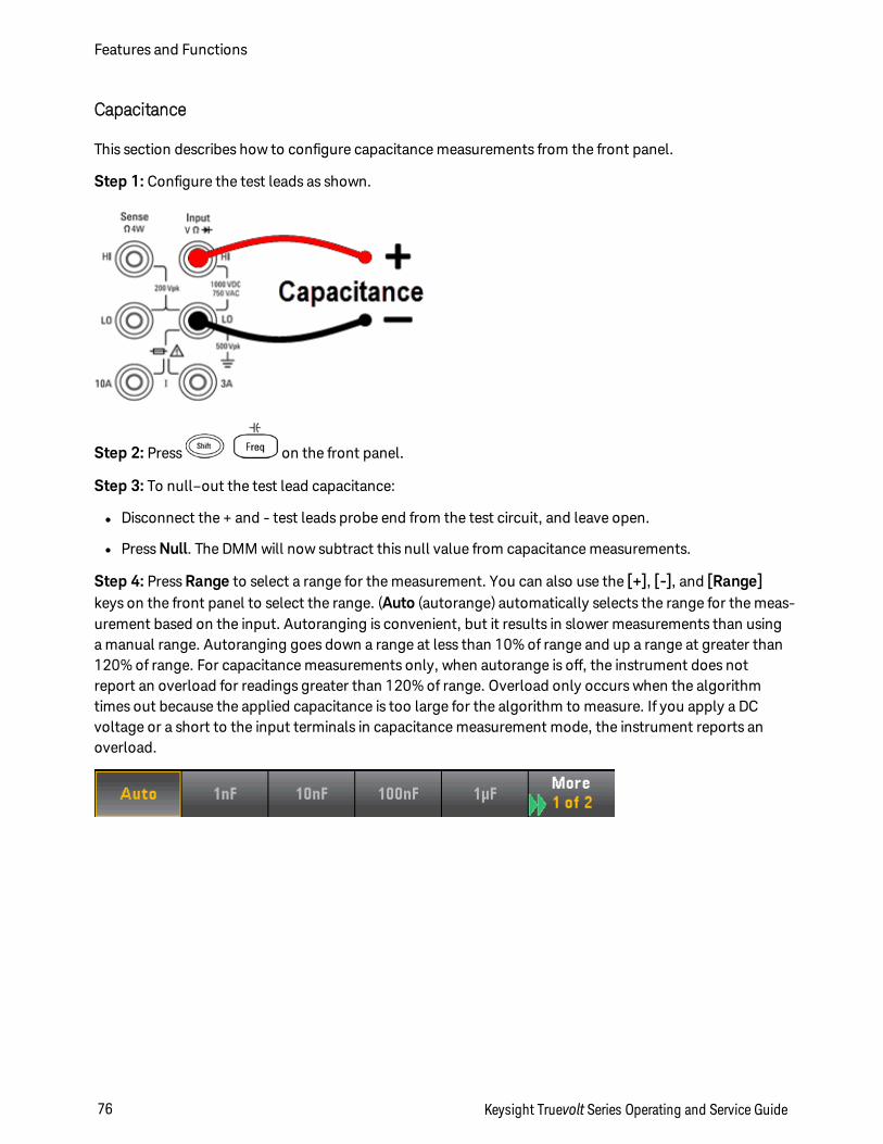
Capacitance
This section describes how to configure capacitance measurements from the front panel.
Step 1: Configure the test leads as shown.
Step 2: Press on the front panel.
Step 3: To null–out the test lead capacitance:
l Disconnect the + and - test leads probe end from the test circuit, and leave open.
l Press Null. The DMM will now subtract this null value from capacitance measurements.
Step 4: Press Range to select a range for the measurement. You can also use the [+], [-], and [Range]keys on the front panel to select the range. (Auto (autorange) automatically selects the range for the meas-urement based on the input. Autoranging is convenient, but it results in slower measurements than usinga manual range. Autoranging goes down a range at less than 10% of range and up a range at greater than120% of range. For capacitance measurements only, when autorange is off, the instrument does notreport an overload for readings greater than 120% of range. Overload only occurs when the algorithmtimes out because the applied capacitance is too large for the algorithm to measure. If you apply a DCvoltage or a short to the input terminals in capacitance measurement mode, the instrument reports anoverload.
Features and Functions
76 Keysight Truevolt Series Operating and Service Guide
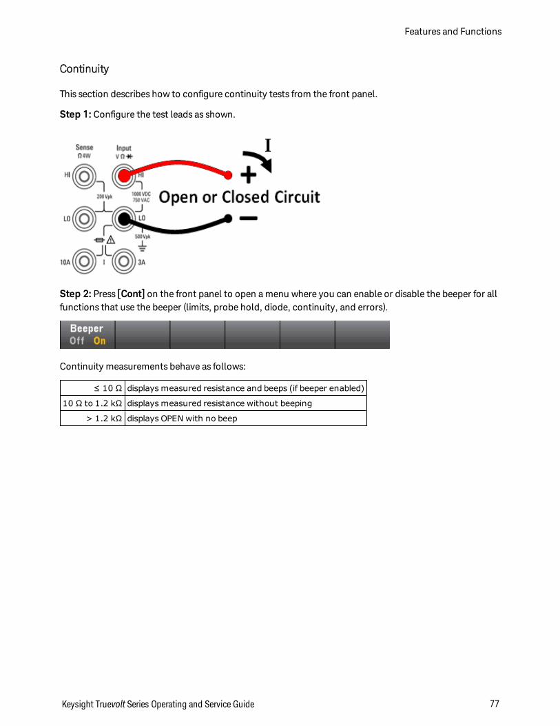
Continuity
This section describes how to configure continuity tests from the front panel.
Step 1: Configure the test leads as shown.
Step 2: Press [Cont] on the front panel to open a menu where you can enable or disable the beeper for allfunctions that use the beeper (limits, probe hold, diode, continuity, and errors).
Continuity measurements behave as follows:
≤ 10 Ω displays measured resistance and beeps (if beeper enabled)
10 Ω to 1.2 kΩ displays measured resistance without beeping
> 1.2 kΩ displays OPEN with no beep
Keysight Truevolt Series Operating and Service Guide 77
Features and Functions
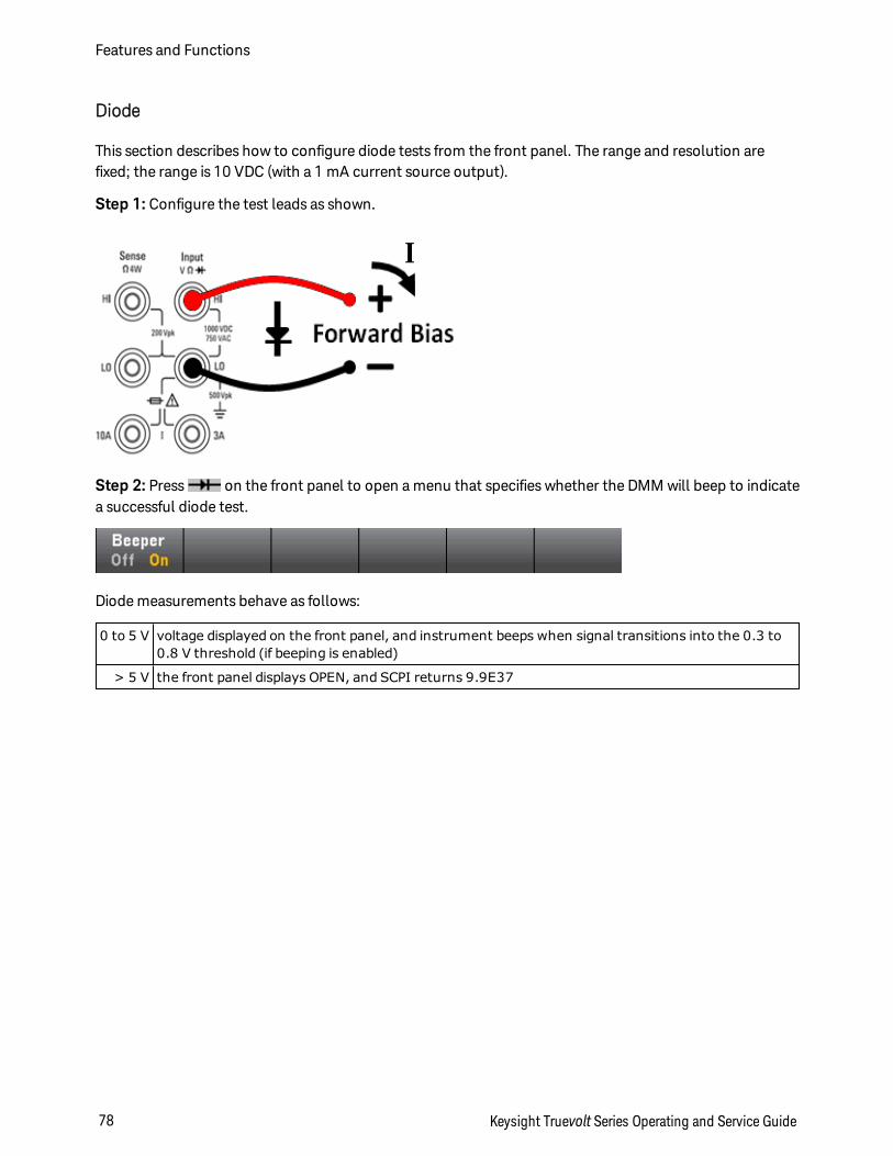
Diode
This section describes how to configure diode tests from the front panel. The range and resolution arefixed; the range is 10 VDC (with a 1 mA current source output).
Step 1: Configure the test leads as shown.
Step 2: Press on the front panel to open a menu that specifies whether the DMM will beep to indicatea successful diode test.
Diode measurements behave as follows:
0 to 5 V voltage displayed on the front panel, and instrument beeps when signal transitions into the 0.3 to0.8 V threshold (if beeping is enabled)
> 5 V the front panel displays OPEN, and SCPI returns 9.9E37
Features and Functions
78 Keysight Truevolt Series Operating and Service Guide
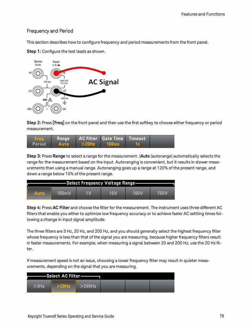
Frequency and Period
This section describes how to configure frequency and period measurements from the front panel.
Step 1: Configure the test leads as shown.
Step 2: Press [Freq] on the front panel and then use the first softkey to choose either frequency or periodmeasurement.
Step 3: Press Range to select a range for the measurement. (Auto (autorange) automatically selects therange for the measurement based on the input. Autoranging is convenient, but it results in slower meas-urements than using a manual range. Autoranging goes up a range at 120% of the present range, anddown a range below 10% of the present range.
Step 4: Press AC Filter and choose the filter for the measurement. The instrument uses three different ACfilters that enable you either to optimize low frequency accuracy or to achieve faster AC settling times fol-lowing a change in input signal amplitude.
The three filters are 3 Hz, 20 Hz, and 200 Hz, and you should generally select the highest frequency filterwhose frequency is less than that of the signal you are measuring, because higher frequency filters resultin faster measurements. For example, when measuring a signal between 20 and 200 Hz, use the 20 Hz fil-ter.
If measurement speed is not an issue, choosing a lower frequency filter may result in quieter meas-urements, depending on the signal that you are measuring.
Keysight Truevolt Series Operating and Service Guide 79
Features and Functions
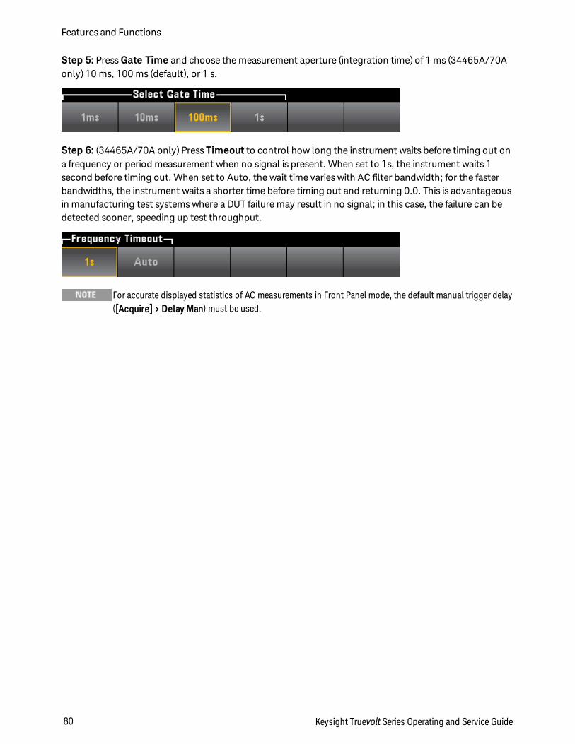
Step 5: Press Gate Time and choose the measurement aperture (integration time) of 1 ms (34465A/70Aonly) 10 ms, 100 ms (default), or 1 s.
Step 6: (34465A/70A only) Press Timeout to control how long the instrument waits before timing out ona frequency or period measurement when no signal is present. When set to 1s, the instrument waits 1second before timing out. When set to Auto, the wait time varies with AC filter bandwidth; for the fasterbandwidths, the instrument waits a shorter time before timing out and returning 0.0. This is advantageousin manufacturing test systems where a DUT failure may result in no signal; in this case, the failure can bedetected sooner, speeding up test throughput.
For accurate displayed statistics of AC measurements in Front Panel mode, the default manual trigger delay([Acquire] > Delay Man) must be used.
Features and Functions
80 Keysight Truevolt Series Operating and Service Guide
Data Logging
The Data Log mode is standard on the 34465A and 34470A only, as is available only from the DMM's frontpanel. Data Log mode provides a front–panel user interface that allows you to set up data logging into theinstrument’s non–volatile memory, or to internal/external file(s), without programming, and without a con-nection to a computer. Once you have finished collecting data, you can view it from the front panel, or youcan transfer the data to your computer. Data Log mode allows you to log a specified number of readings,or readings acquired for a specified period of time, to instrument memory or to internal or external datafiles.
To select Data Log mode, press [Acquire] Acquire > Data Log. You can then select the Sample Interval(time between measurements - for example, 500 ms), Duration as either an amount of Time or a number ofReadings, whether to Start after a Delay or at a specific Time of Day, and whether to Log to Memory or Logto File(s). After configuring the data logging parameters, press [Run/Stop]. Data logging will begin fol-lowing the specified Delay or at the specified Time of Day.
Data Log mode can be used with the DC voltage, DC current, AC voltage, AC current, 2-wire and 4-wireresistance, frequency, period, temperature, capacitance, and ratio measurement functions (diode and con-tinuity are excluded). The maximum reading rate is 1000 readings/s and the maximum duration is 100hours resulting in a maximum number of readings of 360,000,000 to file. The number of readings you canlog to memory depends on the amount of instrument memory. With the MEM option, the limit is2,000,000 readings; without the MEM option, the limit is 50,000 readings. By default, data logging imple-ments auto trigger. The level and external trigger sources are not supported for data logging.
Loss of data possible - local to remote transition clears instrument memory: Whendata logging or digitizing to memory, if you access the instrument from remote (send a SCPIor common command)* and then return to local (by pressing [Local]), the readings inmemory are cleared and the instrument returns to Continuous mode.
For data logging only, you can prevent this situation by data logging to a file instead of tomemory (see Data Log Mode for details). You can also prevent this from happening for datalogging or digitizing by taking steps to keep the instrument from being accessed fromremote. To prevent remote access, you may want to disconnect the LAN, GPIB, and USBinterface cables from the instrument before starting the measurements. To prevent remoteaccess via LAN, you can connect the instrument behind a router to minimize the possibility ofremote access. You can also disable the various I/O interfaces from the front panel menusunder [Utility] > I/O Config.
To view the status of a data logging or digitizing operation remotely, use the instrument’sWeb User Interface. The Web User Interface monitor does not set the instrument to remote.
*When accessed from remote, the instrument will continue data logging or digitizing to completion, and you canretrieve the readings from remote.
Data Logging Overview
This section is a summary of the steps involved in setting up data logging. Detailed steps are describedbelow in Detailed Data Logging Steps.
Keysight Truevolt Series Operating and Service Guide 81
Features and Functions
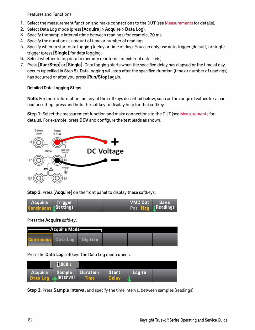
1. Select the measurement function and make connections to the DUT (see Measurements for details).2. Select Data Log mode (press [Acquire] > Acquire > Data Log).3. Specify the sample interval (time between readings) for example, 20 ms.4. Specify the duration as amount of time or number of readings.5. Specify when to start data logging (delay or time of day). You can only use auto trigger (default) or single
trigger (press [Single])for data logging.6. Select whether to log data to memory or internal or external data file(s).7. Press [Run/Stop] or [Single]. Data logging starts when the specified delay has elapsed or the time of day
occurs (specified in Step 5). Data logging will stop after the specified duration (time or number of readings)has occurred or after you press [Run/Stop] again.
Detailed Data Logging Steps
Note: For more information, on any of the softkeys described below, such as the range of values for a par-ticular setting, press and hold the softkey to display help for that softkey.
Step 1: Select the measurement function and make connections to the DUT (see Measurements fordetails). For example, press DCV and configure the test leads as shown.
Step 2: Press [Acquire] on the front panel to display these softkeys:
Press the Acquire softkey.
Press the Data Log softkey. The Data Log menu opens:
Step 3: Press Sample Interval and specify the time interval between samples (readings).
Features and Functions
82 Keysight Truevolt Series Operating and Service Guide
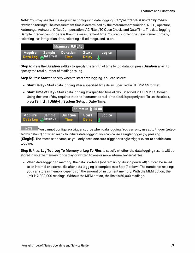
Note: You may see this message when configuring data logging: Sample interval is limited bymeas-urement settings. The measurement time is determined by the measurement function, NPLC, Aperture,Autorange, Autozero, Offset Compensation, AC Filter, TC Open Check, and Gate Time. The data loggingSample Interval cannot be less than the measurement time. You can shorten the measurement time byselecting less integration time, selecting a fixed range, and so on.
Step 4: Press the Duration softkey to specify the length of time to log data, or, press Duration again tospecify the total number of readings to log.
Step 5: Press Start to specify when to start data logging. You can select:
l Start Delay - Starts data logging after a specified time delay. Specified in HH.MM.SS format.
l Start Time of Day - Starts data logging at a specified time of day. Specified in HH.MM.SS format.Using the time of day requires that the instrument’s real-time clock is properly set. To set the clock,press [Shift] > [Utility] > System Setup > Date/Time.
You cannot configure a trigger source when data logging. You can only use auto trigger (selec-ted by default) or, when ready to initiate data logging, you can cause a single trigger (by pressing[Single]). The effect is the same, as you only need one auto trigger or single trigger event to enable datalogging.
Step 6: Press Log To > Log To Memory or Log To Files to specify whether the data logging results will bestored in volatile memory for display or written to one or more internal/external files.
l When data logging to memory, the data is volatile (not remaining during power off) but can be savedto an internal or external file after data logging is complete (see Step 7 below). The number of readingsyou can store in memory depends on the amount of instrument memory. With the MEM option, thelimit is 2,000,000 readings. Without the MEM option, the limit is 50,000 readings.
Keysight Truevolt Series Operating and Service Guide 83
Features and Functions
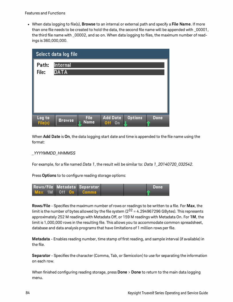
l When data logging to file(s), Browse to an internal or external path and specify a File Name. If morethan one file needs to be created to hold the data, the second file name will be appended with _00001,the third file name with _00002, and so on. When data logging to files, the maximum number of read-ings is 360,000,000.
When Add Date is On, the data logging start date and time is appended to the file name using theformat:
_YYYYMMDD_HHMMSS
For example, for a file named Data 1, the result will be similar to: Data 1_20140720_032542.
Press Options to to configure reading storage options:
Rows/File - Specifies the maximum number of rows or readings to be written to a file. For Max, thelimit is the number of bytes allowed by the file system (232 = 4.294967296 GBytes). This representsapproximately 252 M readings with Metadata Off, or 159 M readings with Metadata On. For 1M, thelimit is 1,000,000 rows in the resulting file. This allows you to accommodate common spreadsheet,database and data analysis programs that have limitations of 1 million rows per file.
Metadata - Enables reading number, time stamp of first reading, and sample interval (if available) inthe file.
Separator - Specifies the character (Comma, Tab, or Semicolon) to use for separating the informationon each row.
When finished configuring reading storage, press Done > Done to return to the main data loggingmenu.
Features and Functions
84 Keysight Truevolt Series Operating and Service Guide
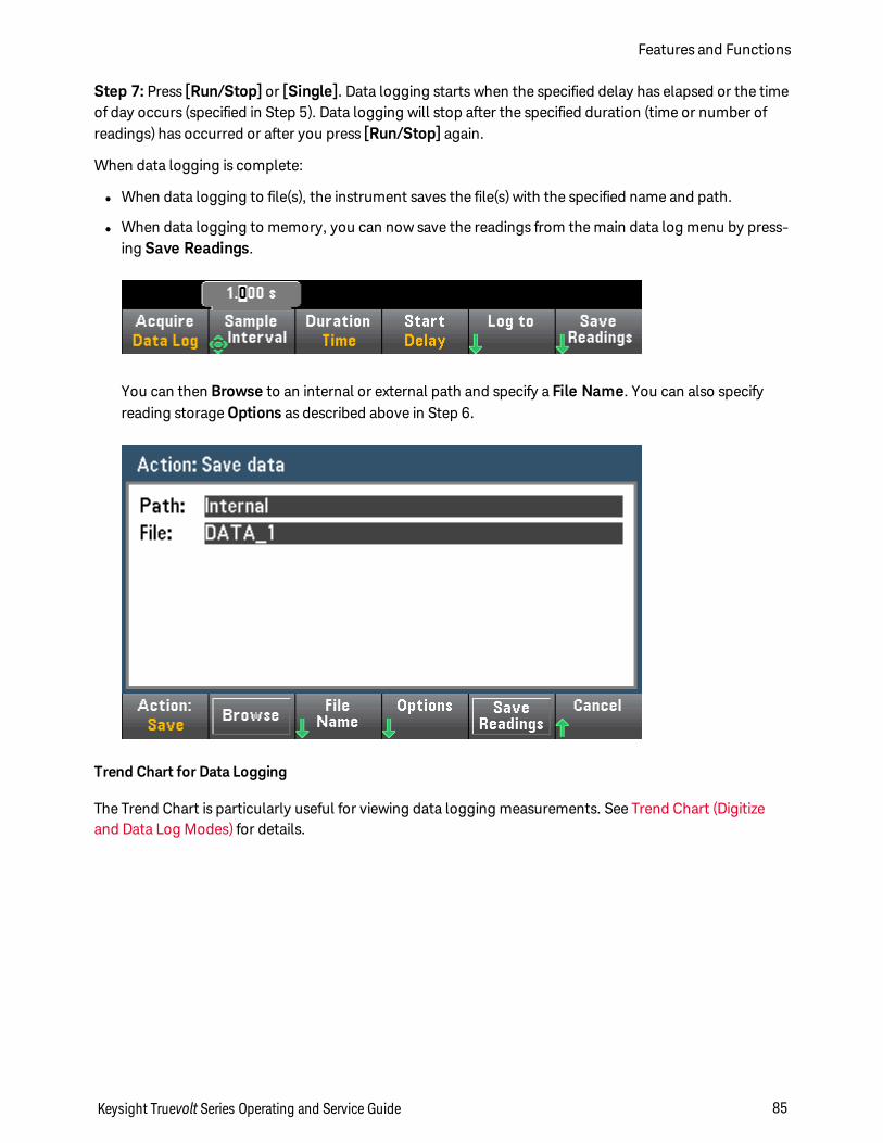
Step 7: Press [Run/Stop] or [Single]. Data logging starts when the specified delay has elapsed or the timeof day occurs (specified in Step 5). Data logging will stop after the specified duration (time or number ofreadings) has occurred or after you press [Run/Stop] again.
When data logging is complete:
l When data logging to file(s), the instrument saves the file(s) with the specified name and path.
l When data logging to memory, you can now save the readings from the main data log menu by press-ing Save Readings.
You can then Browse to an internal or external path and specify a File Name. You can also specifyreading storage Options as described above in Step 6.
Trend Chart for Data Logging
The Trend Chart is particularly useful for viewing data logging measurements. See Trend Chart (Digitizeand Data Log Modes) for details.
Keysight Truevolt Series Operating and Service Guide 85
Features and Functions
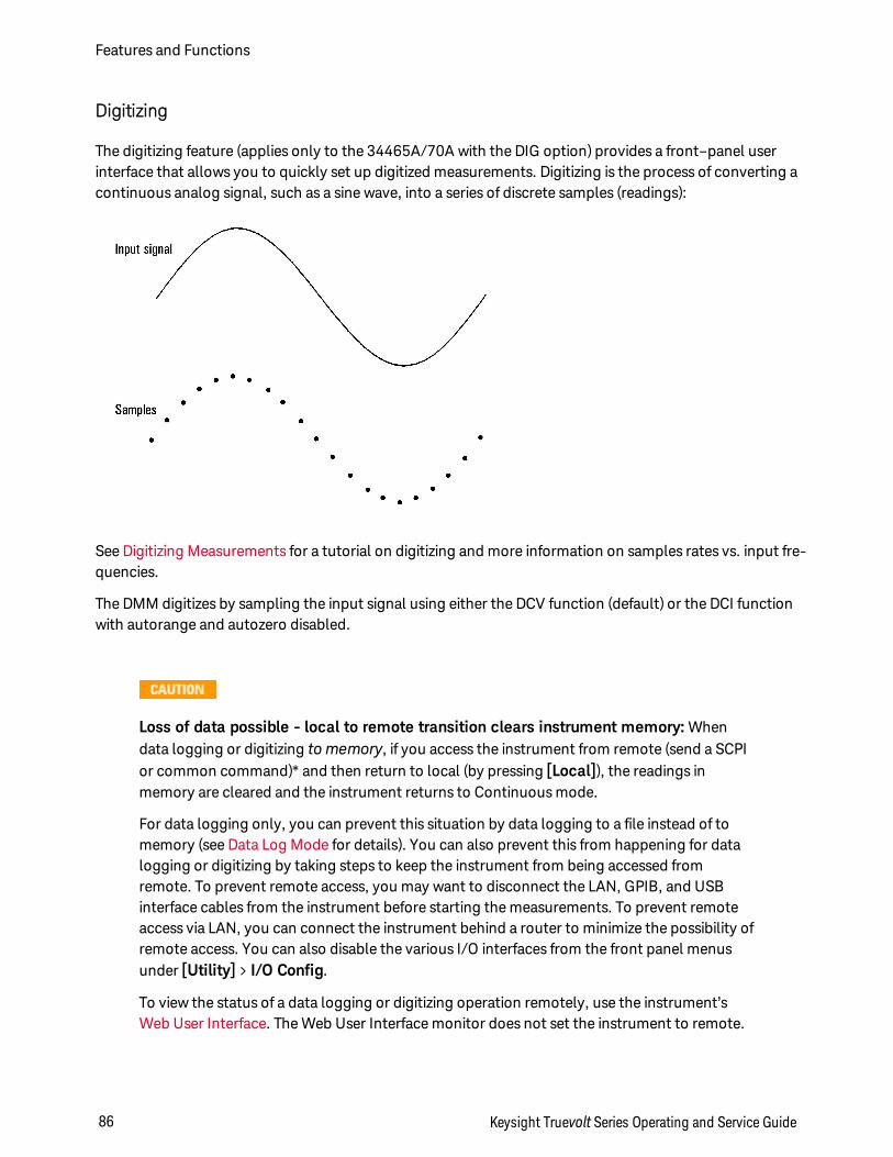
Digitizing
The digitizing feature (applies only to the 34465A/70A with the DIG option) provides a front–panel userinterface that allows you to quickly set up digitized measurements. Digitizing is the process of converting acontinuous analog signal, such as a sine wave, into a series of discrete samples (readings):
See Digitizing Measurements for a tutorial on digitizing and more information on samples rates vs. input fre-quencies.
The DMM digitizes by sampling the input signal using either the DCV function (default) or the DCI functionwith autorange and autozero disabled.
Loss of data possible - local to remote transition clears instrument memory: Whendata logging or digitizing to memory, if you access the instrument from remote (send a SCPIor common command)* and then return to local (by pressing [Local]), the readings inmemory are cleared and the instrument returns to Continuous mode.
For data logging only, you can prevent this situation by data logging to a file instead of tomemory (see Data Log Mode for details). You can also prevent this from happening for datalogging or digitizing by taking steps to keep the instrument from being accessed fromremote. To prevent remote access, you may want to disconnect the LAN, GPIB, and USBinterface cables from the instrument before starting the measurements. To prevent remoteaccess via LAN, you can connect the instrument behind a router to minimize the possibility ofremote access. You can also disable the various I/O interfaces from the front panel menusunder [Utility] > I/O Config.
To view the status of a data logging or digitizing operation remotely, use the instrument’sWeb User Interface. The Web User Interface monitor does not set the instrument to remote.
Features and Functions
86 Keysight Truevolt Series Operating and Service Guide
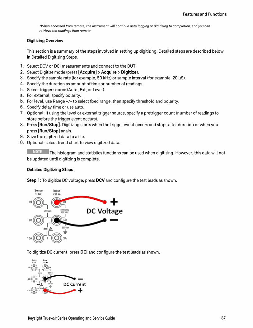
*When accessed from remote, the instrument will continue data logging or digitizing to completion, and you canretrieve the readings from remote.
Digitizing Overview
This section is a summary of the steps involved in setting up digitizing. Detailed steps are described belowin Detailed Digitizing Steps.
1. Select DCV or DCI measurements and connect to the DUT.2. Select Digitize mode (press [Acquire] > Acquire > Digitize).3. Specify the sample rate (for example, 50 kHz) or sample interval (for example, 20 µS).4. Specify the duration as amount of time or number of readings.5. Select trigger source (Auto, Ext, or Level).a. For external, specify polarity.b. For level, use Range +/- to select fixed range, then specify threshold and polarity.6. Specify delay time or use auto.7. Optional: If using the level or external trigger source, specify a pretrigger count (number of readings to
store before the trigger event occurs).8. Press [Run/Stop]. Digitizing starts when the trigger event occurs and stops after duration or when you
press [Run/Stop] again.9. Save the digitized data to a file.
10. Optional: select trend chart to view digitized data.
The histogram and statistics functions can be used when digitizing. However, this data will notbe updated until digitizing is complete.
Detailed Digitizing Steps
Step 1: To digitize DC voltage, press DCV and configure the test leads as shown.
To digitize DC current, press DCI and configure the test leads as shown.
Keysight Truevolt Series Operating and Service Guide 87
Features and Functions
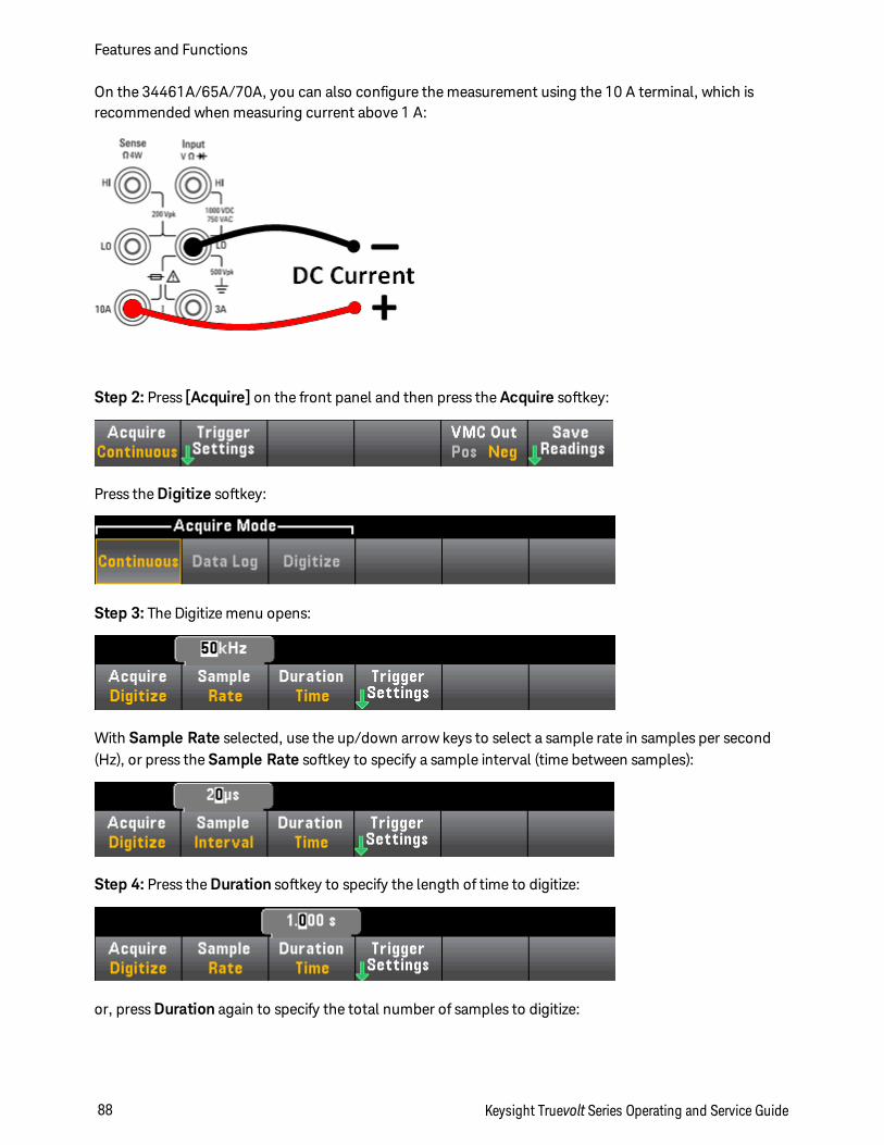
On the 34461A/65A/70A, you can also configure the measurement using the 10 A terminal, which isrecommended when measuring current above 1 A:
Step 2: Press [Acquire] on the front panel and then press the Acquire softkey:
Press the Digitize softkey:
Step 3: The Digitize menu opens:
With Sample Rate selected, use the up/down arrow keys to select a sample rate in samples per second(Hz), or press the Sample Rate softkey to specify a sample interval (time between samples):
Step 4: Press the Duration softkey to specify the length of time to digitize:
or, press Duration again to specify the total number of samples to digitize:
Features and Functions
88 Keysight Truevolt Series Operating and Service Guide
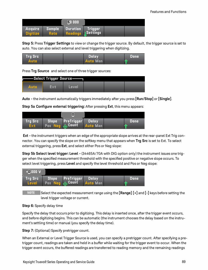
Step 5: Press Trigger Settings to view or change the trigger source. By default, the trigger source is set toauto. You can also select external and level triggering when digitizing.
Press Trg Source and select one of three trigger sources:
Auto - the instrument automatically triggers immediately after you press [Run/Stop] or [Single].
Step 5a Configure external triggering: After pressing Ext, this menu appears:
Ext - the instrument triggers when an edge of the appropriate slope arrives at the rear-panel Ext Trig con-nector. You can specify the slope on the softkey menu that appears when Trg Src is set to Ext. To selectexternal triggering, press Ext, and select either Pos or Neg slope:
Step 5b Select level trigger: Level - (34465A/70A with DIG option only) the instrument issues one trig-ger when the specified measurement threshold with the specified positive or negative slope occurs. Toselect level triggering, press Level and specify the level threshold and Pos or Neg slope:
Select the expected measurement range using the [Range] [+] and [-] keys before setting thelevel trigger voltage or current.
Step 6: Specify delay time
Specify the delay that occurs prior to digitizing. This delay is inserted once, after the trigger event occurs,and before digitizing begins. This can be automatic (the instrument chooses the delay based on the instru-ment’s settling time) or manual (you specify the delay time).
Step 7: (Optional) Specify pretrigger count.
When an External or Level Trigger Source is used, you can specify a pretrigger count. After specifying a pre-trigger count, readings are taken and held in a buffer while waiting for the trigger event to occur. When thetrigger event occurs, the buffered readings are transferred to reading memory and the remaining readings
Keysight Truevolt Series Operating and Service Guide 89
Features and Functions
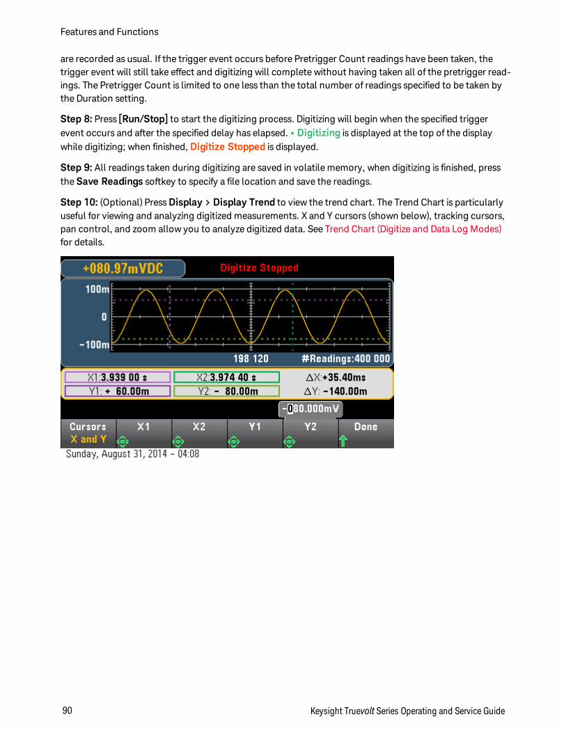
are recorded as usual. If the trigger event occurs before Pretrigger Count readings have been taken, thetrigger event will still take effect and digitizing will complete without having taken all of the pretrigger read-ings. The Pretrigger Count is limited to one less than the total number of readings specified to be taken bythe Duration setting.
Step 8: Press [Run/Stop] to start the digitizing process. Digitizing will begin when the specified triggerevent occurs and after the specified delay has elapsed. • Digitizing is displayed at the top of the displaywhile digitizing; when finished, Digitize Stopped is displayed.
Step 9: All readings taken during digitizing are saved in volatile memory, when digitizing is finished, pressthe Save Readings softkey to specify a file location and save the readings.
Step 10: (Optional) Press Display > Display Trend to view the trend chart. The Trend Chart is particularlyuseful for viewing and analyzing digitized measurements. X and Y cursors (shown below), tracking cursors,pan control, and zoom allow you to analyze digitized data. See Trend Chart (Digitize and Data Log Modes)for details.
Features and Functions
90 Keysight Truevolt Series Operating and Service Guide
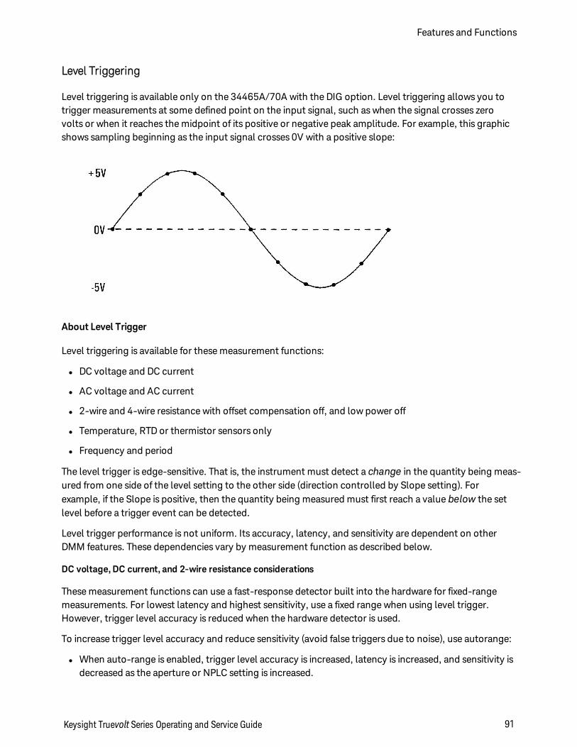
Level Triggering
Level triggering is available only on the 34465A/70A with the DIG option. Level triggering allows you totrigger measurements at some defined point on the input signal, such as when the signal crosses zerovolts or when it reaches the midpoint of its positive or negative peak amplitude. For example, this graphicshows sampling beginning as the input signal crosses 0V with a positive slope:
About Level Trigger
Level triggering is available for these measurement functions:
l DC voltage and DC current
l AC voltage and AC current
l 2-wire and 4-wire resistance with offset compensation off, and low power off
l Temperature, RTD or thermistor sensors only
l Frequency and period
The level trigger is edge-sensitive. That is, the instrument must detect a change in the quantity being meas-ured from one side of the level setting to the other side (direction controlled by Slope setting). Forexample, if the Slope is positive, then the quantity being measured must first reach a value below the setlevel before a trigger event can be detected.
Level trigger performance is not uniform. Its accuracy, latency, and sensitivity are dependent on otherDMM features. These dependencies vary by measurement function as described below.
DC voltage, DC current, and 2-wire resistance considerations
These measurement functions can use a fast-response detector built into the hardware for fixed-rangemeasurements. For lowest latency and highest sensitivity, use a fixed range when using level trigger.However, trigger level accuracy is reduced when the hardware detector is used.
To increase trigger level accuracy and reduce sensitivity (avoid false triggers due to noise), use autorange:
l When auto-range is enabled, trigger level accuracy is increased, latency is increased, and sensitivity isdecreased as the aperture or NPLC setting is increased.
Keysight Truevolt Series Operating and Service Guide 91
Features and Functions

l When auto-range is enabled, trigger level accuracy is increased, latency is increased, and sensitivity isdecreased if autozero is enabled.
l When auto-range is enabled, range changes may be made while waiting for the trigger crossing whichcan cause additional latency/uncertainty.
4-wire resistance and temperature considerations
l Trigger level accuracy is increased, latency is increased, and sensitivity is decreased as aperture orNPLC is increased.
l Fixed range (only available for resistance) eliminates uncertainties (due to range change) in triggerlatency.
AC voltage and AC current considerations
l Trigger latency is increased, and sensitivity is decreased as filter bandwidth is increased.
l Trigger latency can be controlled by trigger delay setting.
l Fixed range eliminates uncertainties (due to range change) in trigger latency.
l Autorange uncertainties become worse as filter bandwidth is increased.
Frequency and period considerations
l Trigger level accuracy is increased, latency is increased, and sensitivity is decreased as gate time isincreased.
l Fixed voltage range eliminates uncertainties (due to range change) in trigger latency.
Features and Functions
92 Keysight Truevolt Series Operating and Service Guide
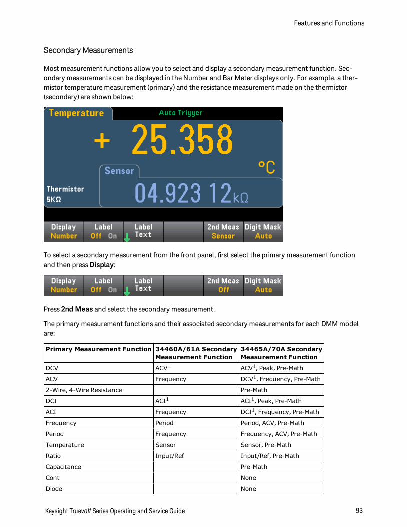
Secondary Measurements
Most measurement functions allow you to select and display a secondary measurement function. Sec-ondary measurements can be displayed in the Number and Bar Meter displays only. For example, a ther-mistor temperature measurement (primary) and the resistance measurement made on the thermistor(secondary) are shown below:
To select a secondary measurement from the front panel, first select the primary measurement functionand then press Display:
Press 2nd Meas and select the secondary measurement.
The primary measurement functions and their associated secondary measurements for each DMM modelare:
Primary Measurement Function 34460A/61A SecondaryMeasurement Function
34465A/70A SecondaryMeasurement Function
DCV ACV1 ACV1, Peak, Pre-Math
ACV Frequency DCV1, Frequency, Pre-Math
2-Wire, 4-Wire Resistance Pre-Math
DCI ACI1 ACI1, Peak, Pre-Math
ACI Frequency DCI1, Frequency, Pre-Math
Frequency Period Period, ACV, Pre-Math
Period Frequency Frequency, ACV, Pre-Math
Temperature Sensor Sensor, Pre-Math
Ratio Input/Ref Input/Ref, Pre-Math
Capacitance Pre-Math
Cont None
Diode None
Keysight Truevolt Series Operating and Service Guide 93
Features and Functions
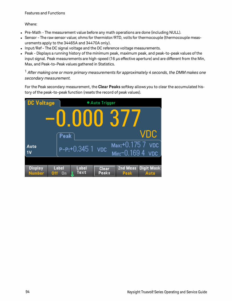
Where:
l Pre-Math - The measurement value before any math operations are done (including NULL).l Sensor - The raw sensor value; ohms for thermistor/RTD, volts for thermocouple (thermocouple meas-
urements apply to the 34465A and 34470A only).l Input/Ref - The DC signal voltage and the DC reference voltage measurements.l Peak - Displays a running history of the minimum peak, maximum peak, and peak-to-peak values of the
input signal. Peak measurements are high-speed (16 µs effective aperture) and are different from the Min,Max, and Peak-to-Peak values gathered in Statistics.
1 After making one ormore primarymeasurements for approximately 4 seconds, the DMMmakes onesecondary measurement.
For the Peak secondary measurement, the Clear Peaks softkey allows you to clear the accumulated his-tory of the peak-to-peak function (resets the record of peak values).
Features and Functions
94 Keysight Truevolt Series Operating and Service Guide
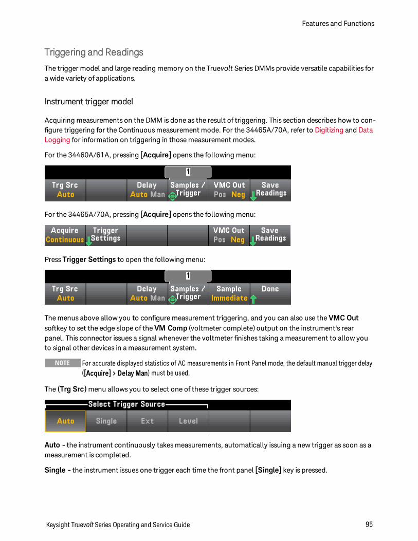
Triggering and Readings
The trigger model and large reading memory on the Truevolt Series DMMs provide versatile capabilities fora wide variety of applications.
Instrument trigger model
Acquiring measurements on the DMM is done as the result of triggering. This section describes how to con-figure triggering for the Continuous measurement mode. For the 34465A/70A, refer to Digitizing and DataLogging for information on triggering in those measurement modes.
For the 34460A/61A, pressing [Acquire] opens the following menu:
For the 34465A/70A, pressing [Acquire] opens the following menu:
Press Trigger Settings to open the following menu:
The menus above allow you to configure measurement triggering, and you can also use the VMC Outsoftkey to set the edge slope of the VM Comp (voltmeter complete) output on the instrument's rearpanel. This connector issues a signal whenever the voltmeter finishes taking a measurement to allow youto signal other devices in a measurement system.
For accurate displayed statistics of AC measurements in Front Panel mode, the default manual trigger delay([Acquire] > Delay Man) must be used.
The (Trg Src) menu allows you to select one of these trigger sources:
Auto - the instrument continuously takes measurements, automatically issuing a new trigger as soon as ameasurement is completed.
Single - the instrument issues one trigger each time the front panel [Single] key is pressed.
Keysight Truevolt Series Operating and Service Guide 95
Features and Functions
Ext - (Ext requires LAN option on 34460A) the instrument issues one trigger each time an edge of theappropriate slope arrives at the rear-panel Ext Trig connector. You can specify the slope on the softkeymenu that appears when Trg Src is set to Ext.
Level - (34465A/70A with DIG option only) the instrument issues one trigger when the specified meas-urement threshold with the specified positive or negative slope occurs.
In the Single, Ext, and Level modes, you can specify the number of samples to be taken per trigger byusing the Samples/Trigger softkey. The Single and Ext modes can both buffer up to one trigger, meaningthat if you press [Single] or receive an external trigger while a series of measurements is in progress, theinstrument will finish that series of measurements and then immediately launch a new series of meas-urements based on the trigger.
If multiple [Single] or external triggers are issued during a series of measurements, all triggers receivedafter the first are discarded.
The [Acquire] menu also configures the delay that occurs before each measurement is taken, regardlessof the trigger mode (Auto, Single, or Ext). This may be either automatic (the delay is based on the DMM’ssettling time) or manual (you specify the delay time).
Finally, note the [Run/Stop] and [Single] keys on the front panel. In Auto trigger mode, pressing [Run-/Stop] stops and resumes measurements, and pressing [Single] switches the instrument to single triggermode. In the Single and Ext modes, pressing [Run/Stop] stops readings if they are in progress, or switchesthe mode to Auto if readings are stopped.
Features and Functions
96 Keysight Truevolt Series Operating and Service Guide
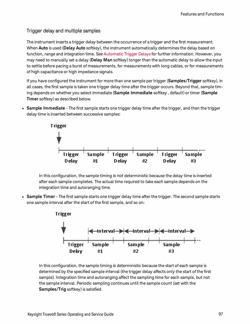
Trigger delay and multiple samples
The instrument inserts a trigger delay between the occurrence of a trigger and the first measurement.When Auto is used (Delay Auto softkey), the instrument automatically determines the delay based onfunction, range and integration time. See Automatic Trigger Delays for further information. However, youmay need to manually set a delay (Delay Man softkey) longer than the automatic delay to allow the inputto settle before pacing a burst of measurements, for measurements with long cables, or for measurementsof high capacitance or high impedance signals.
If you have configured the instrument for more than one sample per trigger (Samples/Trigger softkey), inall cases, the first sample is taken one trigger delay time after the trigger occurs. Beyond that, sample tim-ing depends on whether you select immediate (Sample Immediate softkey , default) or timer (SampleTimer softkey) as described below.
l Sample Immediate - The first sample starts one trigger delay time after the trigger, and then the triggerdelay time is inserted between successive samples:
In this configuration, the sample timing is not deterministic because the delay time is insertedafter each sample completes. The actual time required to take each sample depends on theintegration time and autoranging time.
l Sample Timer - The first sample starts one trigger delay time after the trigger. The second sample startsone sample interval after the start of the first sample, and so on:
In this configuration, the sample timing is deterministic because the start of each sample isdetermined by the specified sample interval (the trigger delay affects only the start of the firstsample). Integration time and autoranging affect the sampling time for each sample, but notthe sample interval. Periodic sampling continues until the sample count (set with theSamples/Trig softkey) is satisfied.
Keysight Truevolt Series Operating and Service Guide 97
Features and Functions
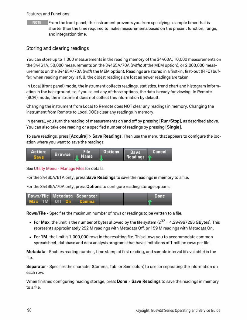
From the front panel, the instrument prevents you from specifying a sample timer that isshorter than the time required to make measurements based on the present function, range,and integration time.
Storing and clearing readings
You can store up to 1,000 measurements in the reading memory of the 34460A, 10,000 measurements onthe 34461A, 50,000 measurements on the 34465A/70A (without the MEM option), or 2,000,000 meas-urements on the 34465A/70A (with the MEM option). Readings are stored in a first-in, first-out (FIFO) buf-fer; when reading memory is full, the oldest readings are lost as newer readings are taken.
In Local (front panel) mode, the instrument collects readings, statistics, trend chart and histogram inform-ation in the background, so if you select any of those options, the data is ready for viewing. In Remote(SCPI) mode, the instrument does not collect this information by default.
Changing the instrument from Local to Remote does NOT clear any readings in memory. Changing theinstrument from Remote to Local DOEs clear any readings in memory.
In general, you turn the reading of measurements on and off by pressing [Run/Stop], as described above.You can also take one reading or a specified number of readings by pressing [Single].
To save readings, press [Acquire] > Save Readings. Then use the menu that appears to configure the loc-ation where you want to save the readings:
See Utility Menu - Manage Files for details.
For the 34460A/61A only, press Save Readings to save the readings in memory to a file.
For the 34465A/70A only, press Options to configure reading storage options:
Rows/File - Specifies the maximum number of rows or readings to be written to a file.
l For Max, the limit is the number of bytes allowed by the file system (232 = 4.294967296 GBytes). Thisrepresents approximately 252 M readings with Metadata Off, or 159 M readings with Metadata On.
l For 1M, the limit is 1,000,000 rows in the resulting file. This allows you to accommodate commonspreadsheet, database and data analysis programs that have limitations of 1 million rows per file.
Metadata - Enables reading number, time stamp of first reading, and sample interval (if available) in thefile.
Separator - Specifies the character (Comma, Tab, or Semicolon) to use for separating the information oneach row.
When finished configuring reading storage, press Done > Save Readings to save the readings in memoryto a file.
Features and Functions
98 Keysight Truevolt Series Operating and Service Guide
Clearing Reading Memory
The following actions clear reading memory:
l Changing the measurement function
l Pressing any Clear Readings softkey
l Transitioning in or out of Probe Hold
l Changing temperature units
l Changing any dB/dBm parameters
l Changing any histogram binning parameter
l Changing the temperature probe or R0
l Recalling a stored state
l Calibrating the instrument
l Switching between 3 A and 10 A inputs
l Changing the position of the Front/Rear switch
l Transferring from Remote to Local mode
l Turning Null on or off or changing the Null value
These actions do not clear reading memory:
l Changing measurement parameters, such as range and aperture.
l Turning limits on or off, or adjusting limit values
l Pressing [Run/Stop] in front panel auto trigger mode
l Changing the trend chart Recent/All softkey (34461A/65A/70A only)
l Changing samples per trigger or trigger delay
l Changing display modes
l Changing the VM Comp output polarity
l Changing the digit mask
l Changing the histogram, bar meter, or trend chart scale
l Changing user preferences
l Executing self-test
Keysight Truevolt Series Operating and Service Guide 99
Features and Functions
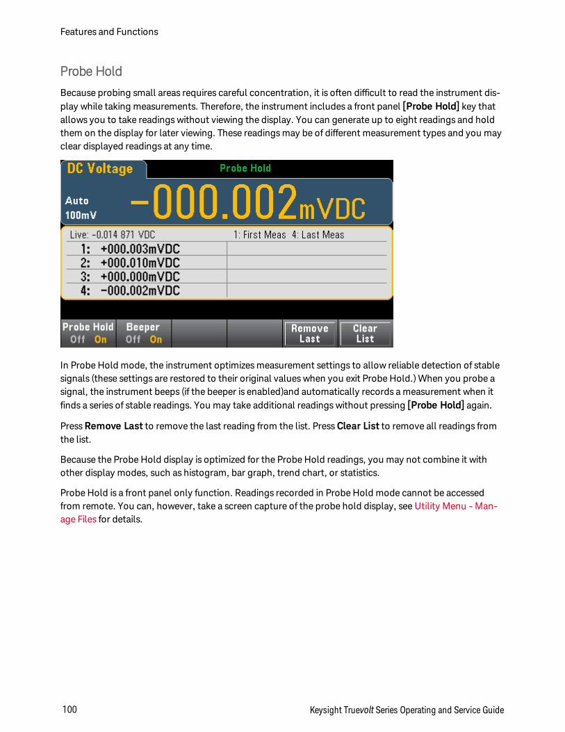
Probe Hold
Because probing small areas requires careful concentration, it is often difficult to read the instrument dis-play while taking measurements. Therefore, the instrument includes a front panel [Probe Hold] key thatallows you to take readings without viewing the display. You can generate up to eight readings and holdthem on the display for later viewing. These readings may be of different measurement types and you mayclear displayed readings at any time.
In Probe Hold mode, the instrument optimizes measurement settings to allow reliable detection of stablesignals (these settings are restored to their original values when you exit Probe Hold.) When you probe asignal, the instrument beeps (if the beeper is enabled)and automatically records a measurement when itfinds a series of stable readings. You may take additional readings without pressing [Probe Hold] again.
Press Remove Last to remove the last reading from the list. Press Clear List to remove all readings fromthe list.
Because the Probe Hold display is optimized for the Probe Hold readings, you may not combine it withother display modes, such as histogram, bar graph, trend chart, or statistics.
Probe Hold is a front panel only function. Readings recorded in Probe Hold mode cannot be accessedfrom remote. You can, however, take a screen capture of the probe hold display, see Utility Menu - Man-age Files for details.
Features and Functions
100 Keysight Truevolt Series Operating and Service Guide
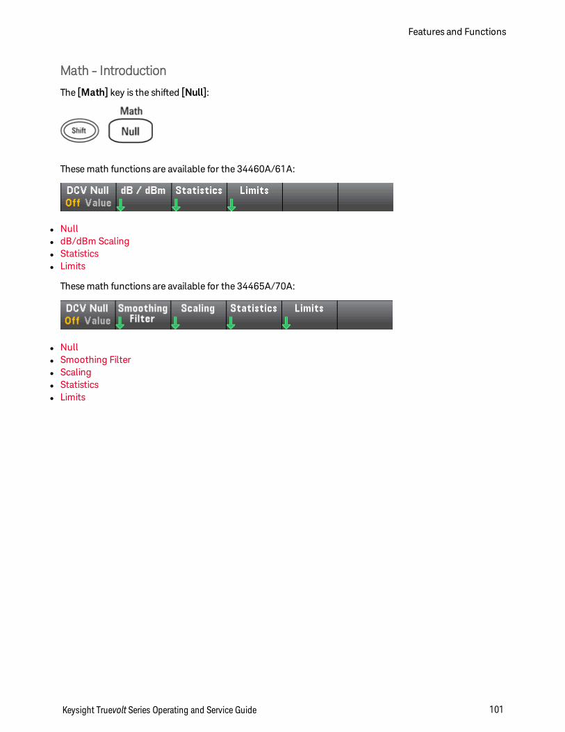
Math - Introduction
The [Math] key is the shifted [Null]:
These math functions are available for the 34460A/61A:
l Nulll dB/dBm Scalingl Statisticsl Limits
These math functions are available for the 34465A/70A:
l Nulll Smoothing Filterl Scalingl Statisticsl Limits
Keysight Truevolt Series Operating and Service Guide 101
Features and Functions
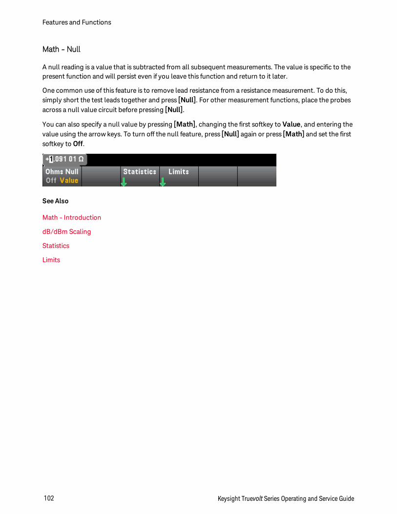
Math - Null
A null reading is a value that is subtracted from all subsequent measurements. The value is specific to thepresent function and will persist even if you leave this function and return to it later.
One common use of this feature is to remove lead resistance from a resistance measurement. To do this,simply short the test leads together and press [Null]. For other measurement functions, place the probesacross a null value circuit before pressing [Null].
You can also specify a null value by pressing [Math], changing the first softkey to Value, and entering thevalue using the arrow keys. To turn off the null feature, press [Null] again or press [Math] and set the firstsoftkey to Off.
See Also
Math - Introduction
dB/dBm Scaling
Statistics
Limits
Features and Functions
102 Keysight Truevolt Series Operating and Service Guide
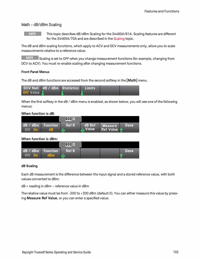
Math - dB/dBm Scaling
This topic describes dB/dBm Scaling for the 34460A/61A. Scaling features are differentfor the 34465A/70A and are described in the Scaling topic.
The dB and dBm scaling functions, which apply to ACV and DCV measurements only, allow you to scalemeasurements relative to a reference value.
Scaling is set to OFF when you change measurement functions (for example, changing fromDCV to ACV). You must re-enable scaling after changing measurement functions.
Front Panel Menus
The dB and dBm functions are accessed from the second softkey in the [Math] menu.
When the first softkey in the dB / dBm menu is enabled, as shown below, you will see one of the followingmenus:
When function is dB:
When function is dBm:
dB Scaling
Each dB measurement is the difference between the input signal and a stored reference value, with bothvalues converted to dBm:
dB = reading in dBm – reference value in dBm
The relative value must be from -200 to +200 dBm (default 0). You can either measure this value by press-ing Measure Ref Value, or you can enter a specified value.
Keysight Truevolt Series Operating and Service Guide 103
Features and Functions
dBm Scaling
The dBm function is logarithmic, comparing power delivered to a reference resistance, relative to 1 mil-liwatt:
dBm = 10 x log10 ( reading2 / reference resistance / 1 mW )
The reference resistance value (Ref R) may be 50, 75, 93, 110, 124, 125, 135, 150, 250, 300, 500, 600(default), 800, 900, 1000, 1200, or 8000 Ω. Press Ref R and use the front panel up and down arrows tomake your selection.
See Also
Math - Introduction
Null
Statistics
Limits
Features and Functions
104 Keysight Truevolt Series Operating and Service Guide
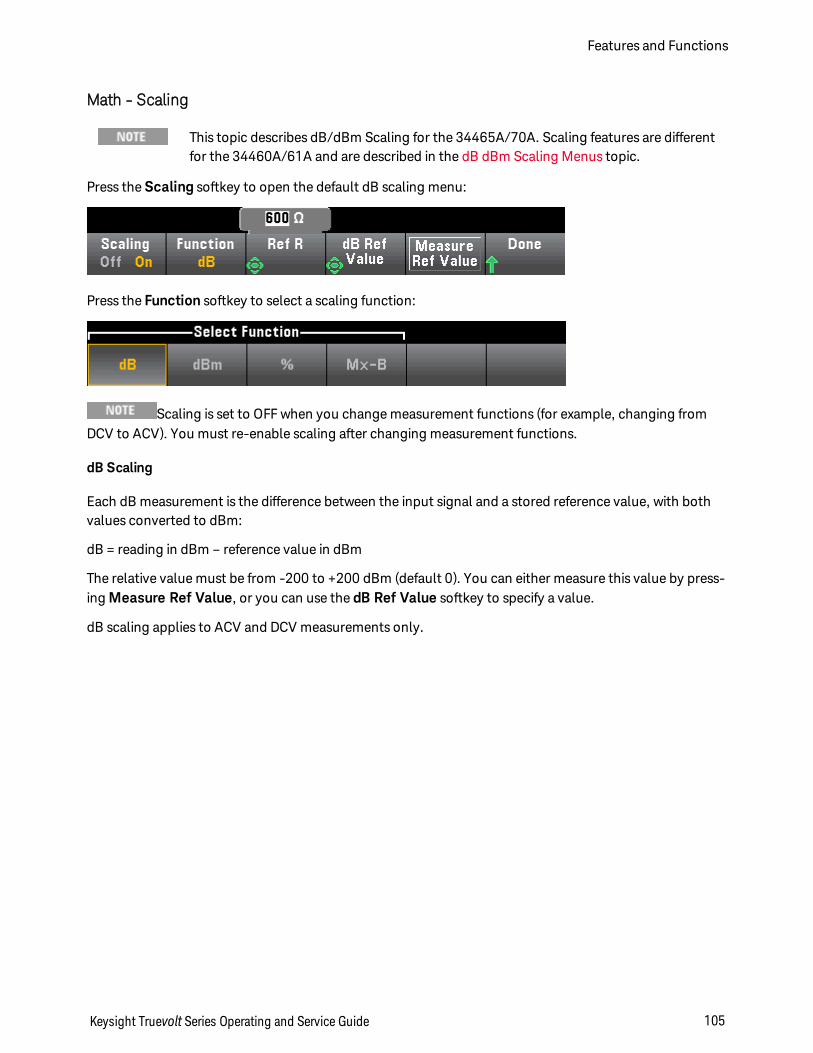
Math - Scaling
This topic describes dB/dBm Scaling for the 34465A/70A. Scaling features are differentfor the 34460A/61A and are described in the dB dBm Scaling Menus topic.
Press the Scaling softkey to open the default dB scaling menu:
Press the Function softkey to select a scaling function:
Scaling is set to OFF when you change measurement functions (for example, changing fromDCV to ACV). You must re-enable scaling after changing measurement functions.
dB Scaling
Each dB measurement is the difference between the input signal and a stored reference value, with bothvalues converted to dBm:
dB = reading in dBm – reference value in dBm
The relative value must be from -200 to +200 dBm (default 0). You can either measure this value by press-ing Measure Ref Value, or you can use the dB Ref Value softkey to specify a value.
dB scaling applies to ACV and DCV measurements only.
Keysight Truevolt Series Operating and Service Guide 105
Features and Functions
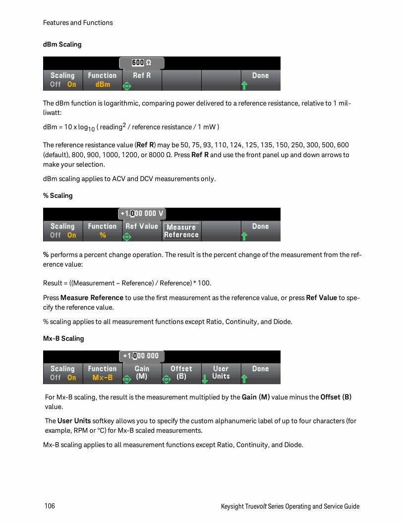
dBm Scaling
The dBm function is logarithmic, comparing power delivered to a reference resistance, relative to 1 mil-liwatt:
dBm = 10 x log10 ( reading2 / reference resistance / 1 mW )
The reference resistance value (Ref R) may be 50, 75, 93, 110, 124, 125, 135, 150, 250, 300, 500, 600(default), 800, 900, 1000, 1200, or 8000 Ω. Press Ref R and use the front panel up and down arrows tomake your selection.
dBm scaling applies to ACV and DCV measurements only.
% Scaling
% performs a percent change operation. The result is the percent change of the measurement from the ref-erence value:
Result = ((Measurement – Reference) / Reference) * 100.
Press Measure Reference to use the first measurement as the reference value, or press Ref Value to spe-cify the reference value.
% scaling applies to all measurement functions except Ratio, Continuity, and Diode.
Mx-B Scaling
For Mx-B scaling, the result is the measurement multiplied by the Gain (M) value minus the Offset (B)value.
The User Units softkey allows you to specify the custom alphanumeric label of up to four characters (forexample, RPM or °C) for Mx-B scaled measurements.
Mx-B scaling applies to all measurement functions except Ratio, Continuity, and Diode.
Features and Functions
106 Keysight Truevolt Series Operating and Service Guide

See Also
Math - Introduction
Null
Statistics
Limits
Keysight Truevolt Series Operating and Service Guide 107
Features and Functions
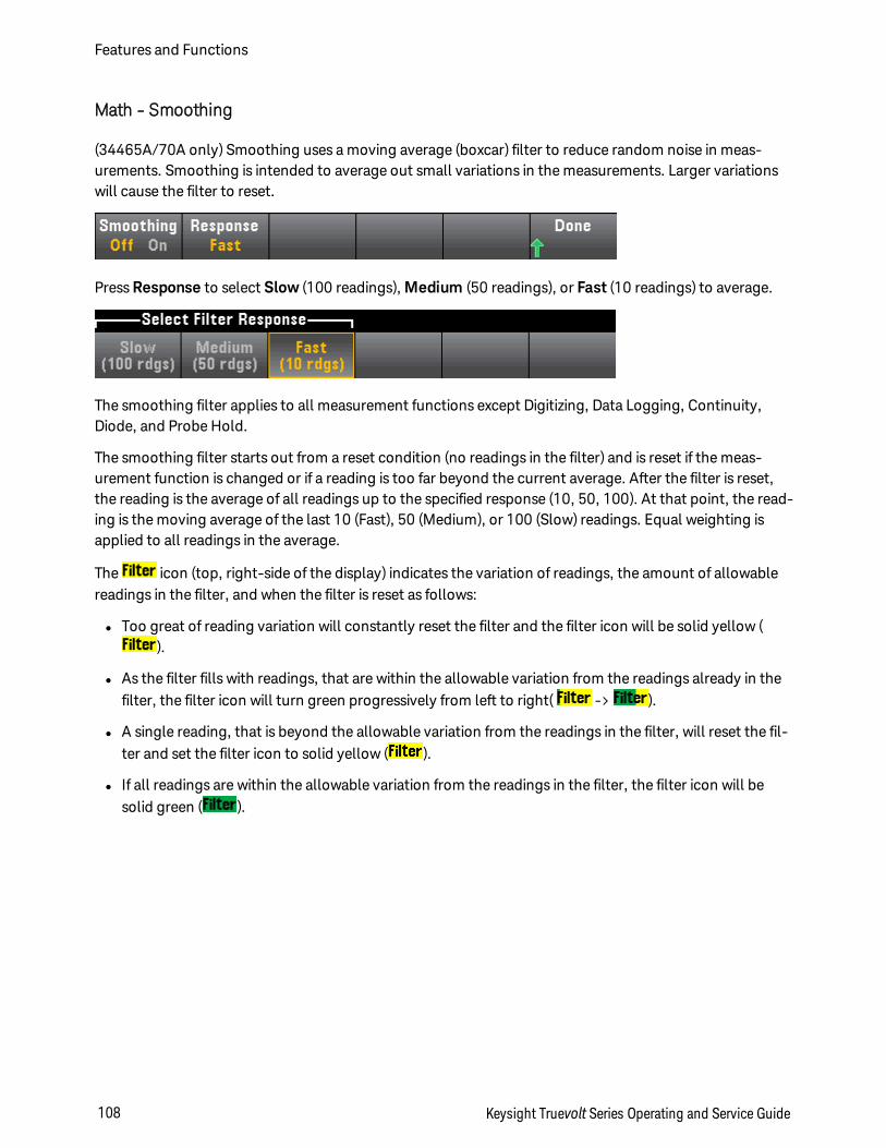
Math - Smoothing
(34465A/70A only) Smoothing uses a moving average (boxcar) filter to reduce random noise in meas-urements. Smoothing is intended to average out small variations in the measurements. Larger variationswill cause the filter to reset.
Press Response to select Slow (100 readings), Medium (50 readings), or Fast (10 readings) to average.
The smoothing filter applies to all measurement functions except Digitizing, Data Logging, Continuity,Diode, and Probe Hold.
The smoothing filter starts out from a reset condition (no readings in the filter) and is reset if the meas-urement function is changed or if a reading is too far beyond the current average. After the filter is reset,the reading is the average of all readings up to the specified response (10, 50, 100). At that point, the read-ing is the moving average of the last 10 (Fast), 50 (Medium), or 100 (Slow) readings. Equal weighting isapplied to all readings in the average.
The icon (top, right-side of the display) indicates the variation of readings, the amount of allowablereadings in the filter, and when the filter is reset as follows:
l Too great of reading variation will constantly reset the filter and the filter icon will be solid yellow ().
l As the filter fills with readings, that are within the allowable variation from the readings already in thefilter, the filter icon will turn green progressively from left to right( -> ).
l A single reading, that is beyond the allowable variation from the readings in the filter, will reset the fil-ter and set the filter icon to solid yellow ( ).
l If all readings are within the allowable variation from the readings in the filter, the filter icon will besolid green ( ).
Features and Functions
108 Keysight Truevolt Series Operating and Service Guide
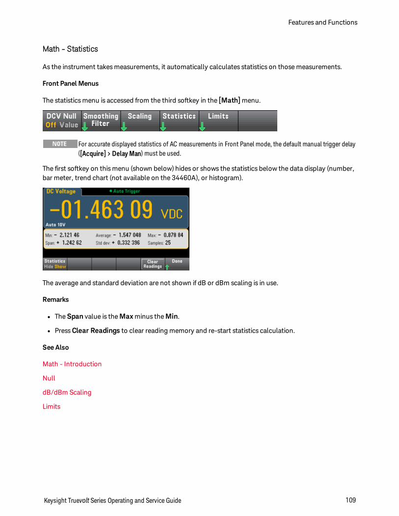
Math - Statistics
As the instrument takes measurements, it automatically calculates statistics on those measurements.
Front Panel Menus
The statistics menu is accessed from the third softkey in the [Math] menu.
For accurate displayed statistics of AC measurements in Front Panel mode, the default manual trigger delay([Acquire] > Delay Man) must be used.
The first softkey on this menu (shown below) hides or shows the statistics below the data display (number,bar meter, trend chart (not available on the 34460A), or histogram).
The average and standard deviation are not shown if dB or dBm scaling is in use.
Remarks
l The Span value is the Max minus the Min.
l Press Clear Readings to clear reading memory and re-start statistics calculation.
See Also
Math - Introduction
Null
dB/dBm Scaling
Limits
Keysight Truevolt Series Operating and Service Guide 109
Features and Functions
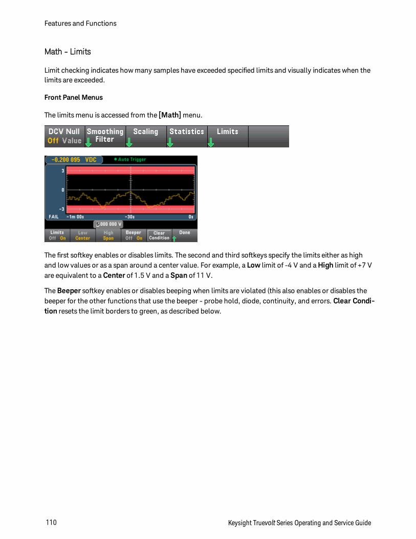
Math - Limits
Limit checking indicates how many samples have exceeded specified limits and visually indicates when thelimits are exceeded.
Front Panel Menus
The limits menu is accessed from the [Math] menu.
The first softkey enables or disables limits. The second and third softkeys specify the limits either as highand low values or as a span around a center value. For example, a Low limit of -4 V and a High limit of +7 Vare equivalent to a Center of 1.5 V and a Span of 11 V.
The Beeper softkey enables or disables beeping when limits are violated (this also enables or disables thebeeper for the other functions that use the beeper - probe hold, diode, continuity, and errors. Clear Condi-tion resets the limit borders to green, as described below.
Features and Functions
110 Keysight Truevolt Series Operating and Service Guide
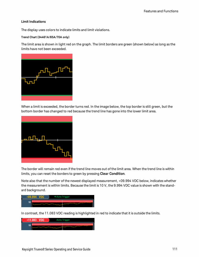
Limit Indications
The display uses colors to indicate limits and limit violations.
Trend Chart (34461A/65A/70A only)
The limit area is shown in light red on the graph. The limit borders are green (shown below) as long as thelimits have not been exceeded.
When a limit is exceeded, the border turns red. In the image below, the top border is still green, but thebottom border has changed to red because the trend line has gone into the lower limit area.
The border will remain red even if the trend line moves out of the limit area. When the trend line is withinlimits, you can reset the borders to green by pressing Clear Condition.
Note also that the number of the newest displayed measurement, +09.994 VDC below, indicates whetherthe measurement is within limits. Because the limit is 10 V, the 9.994 VDC value is shown with the stand-ard background.
In contrast, the 11.083 VDC reading is highlighted in red to indicate that it is outside the limits.
Keysight Truevolt Series Operating and Service Guide 111
Features and Functions
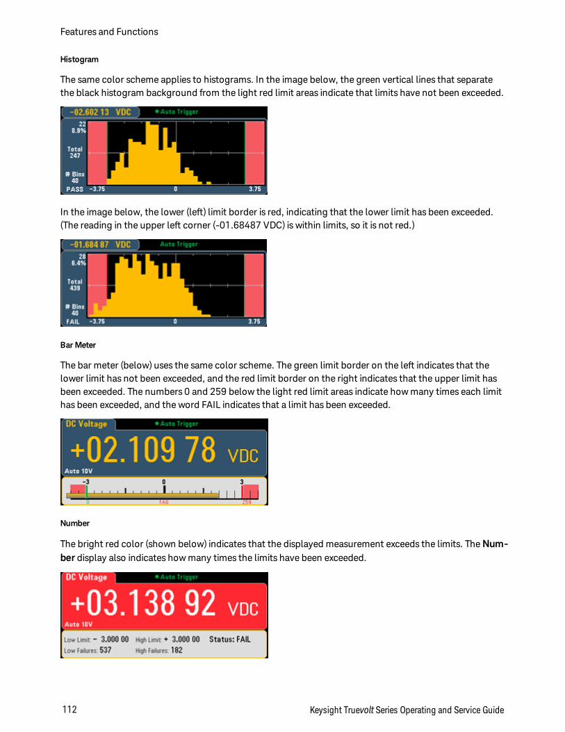
Histogram
The same color scheme applies to histograms. In the image below, the green vertical lines that separatethe black histogram background from the light red limit areas indicate that limits have not been exceeded.
In the image below, the lower (left) limit border is red, indicating that the lower limit has been exceeded.(The reading in the upper left corner (-01.68487 VDC) is within limits, so it is not red.)
Bar Meter
The bar meter (below) uses the same color scheme. The green limit border on the left indicates that thelower limit has not been exceeded, and the red limit border on the right indicates that the upper limit hasbeen exceeded. The numbers 0 and 259 below the light red limit areas indicate how many times each limithas been exceeded, and the word FAIL indicates that a limit has been exceeded.
Number
The bright red color (shown below) indicates that the displayed measurement exceeds the limits. The Num-ber display also indicates how many times the limits have been exceeded.
Features and Functions
112 Keysight Truevolt Series Operating and Service Guide

See Also
Math - Introduction
Null
dB/dBm Scaling
Statistics
Keysight Truevolt Series Operating and Service Guide 113
Features and Functions
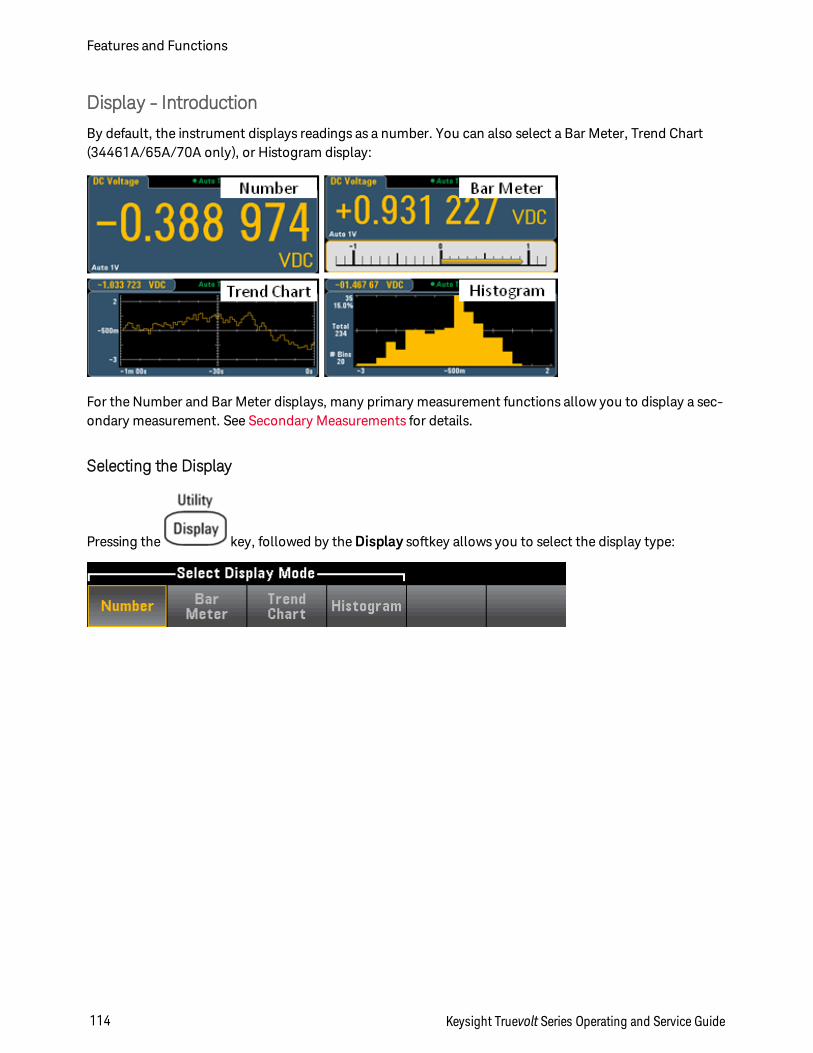
Display - Introduction
By default, the instrument displays readings as a number. You can also select a Bar Meter, Trend Chart(34461A/65A/70A only), or Histogram display:
For the Number and Bar Meter displays, many primary measurement functions allow you to display a sec-ondary measurement. See Secondary Measurements for details.
Selecting the Display
Pressing the key, followed by the Display softkey allows you to select the display type:
Features and Functions
114 Keysight Truevolt Series Operating and Service Guide
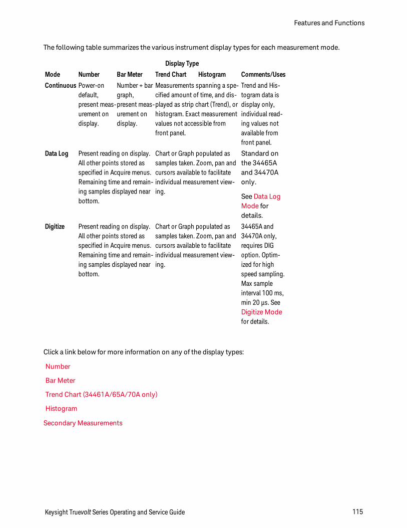
The following table summarizes the various instrument display types for each measurement mode.
Display Type
Mode Number Bar Meter Trend Chart Histogram Comments/Uses
Continuous Power-ondefault,present meas-urement ondisplay.
Number + bargraph,present meas-urement ondisplay.
Measurements spanning a spe-cified amount of time, and dis-played as strip chart (Trend), orhistogram. Exact measurementvalues not accessible fromfront panel.
Trend and His-togram data isdisplay only,individual read-ing values notavailable fromfront panel.
Data Log Present reading on display.All other points stored asspecified in Acquire menus.Remaining time and remain-ing samples displayed nearbottom.
Chart or Graph populated assamples taken. Zoom, pan andcursors available to facilitateindividual measurement view-ing.
Standard onthe 34465Aand 34470Aonly.
See Data LogMode fordetails.
Digitize Present reading on display.All other points stored asspecified in Acquire menus.Remaining time and remain-ing samples displayed nearbottom.
Chart or Graph populated assamples taken. Zoom, pan andcursors available to facilitateindividual measurement view-ing.
34465A and34470A only,requires DIGoption. Optim-ized for highspeed sampling.Max sampleinterval 100 ms,min 20 µs. SeeDigitize Modefor details.
Click a link below for more information on any of the display types:
Number
Bar Meter
Trend Chart (34461A/65A/70A only)
Histogram
Secondary Measurements
Keysight Truevolt Series Operating and Service Guide 115
Features and Functions
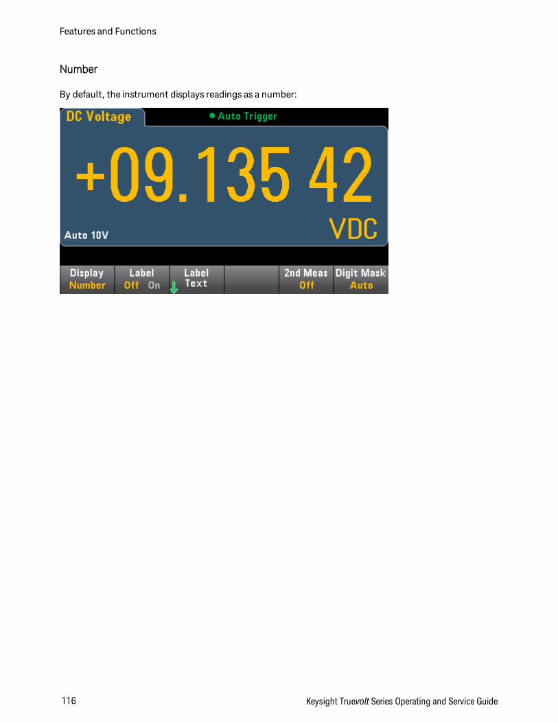
Number
By default, the instrument displays readings as a number:
Features and Functions
116 Keysight Truevolt Series Operating and Service Guide
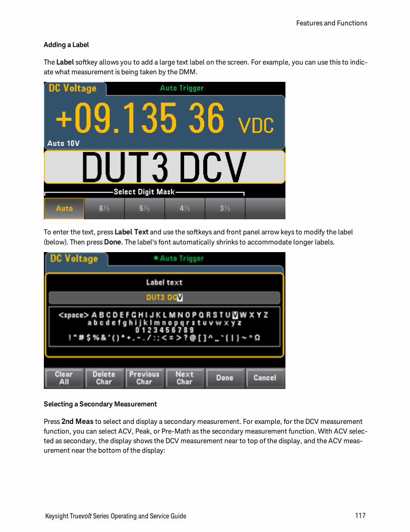
Adding a Label
The Label softkey allows you to add a large text label on the screen. For example, you can use this to indic-ate what measurement is being taken by the DMM.
To enter the text, press Label Text and use the softkeys and front panel arrow keys to modify the label(below). Then press Done. The label's font automatically shrinks to accommodate longer labels.
Selecting a Secondary Measurement
Press 2nd Meas to select and display a secondary measurement. For example, for the DCV measurementfunction, you can select ACV, Peak, or Pre-Math as the secondary measurement function. With ACV selec-ted as secondary, the display shows the DCV measurement near to top of the display, and the ACV meas-urement near the bottom of the display:
Keysight Truevolt Series Operating and Service Guide 117
Features and Functions
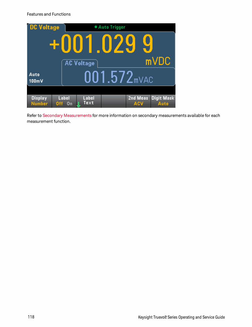
Refer to Secondary Measurements for more information on secondary measurements available for eachmeasurement function.
Features and Functions
118 Keysight Truevolt Series Operating and Service Guide
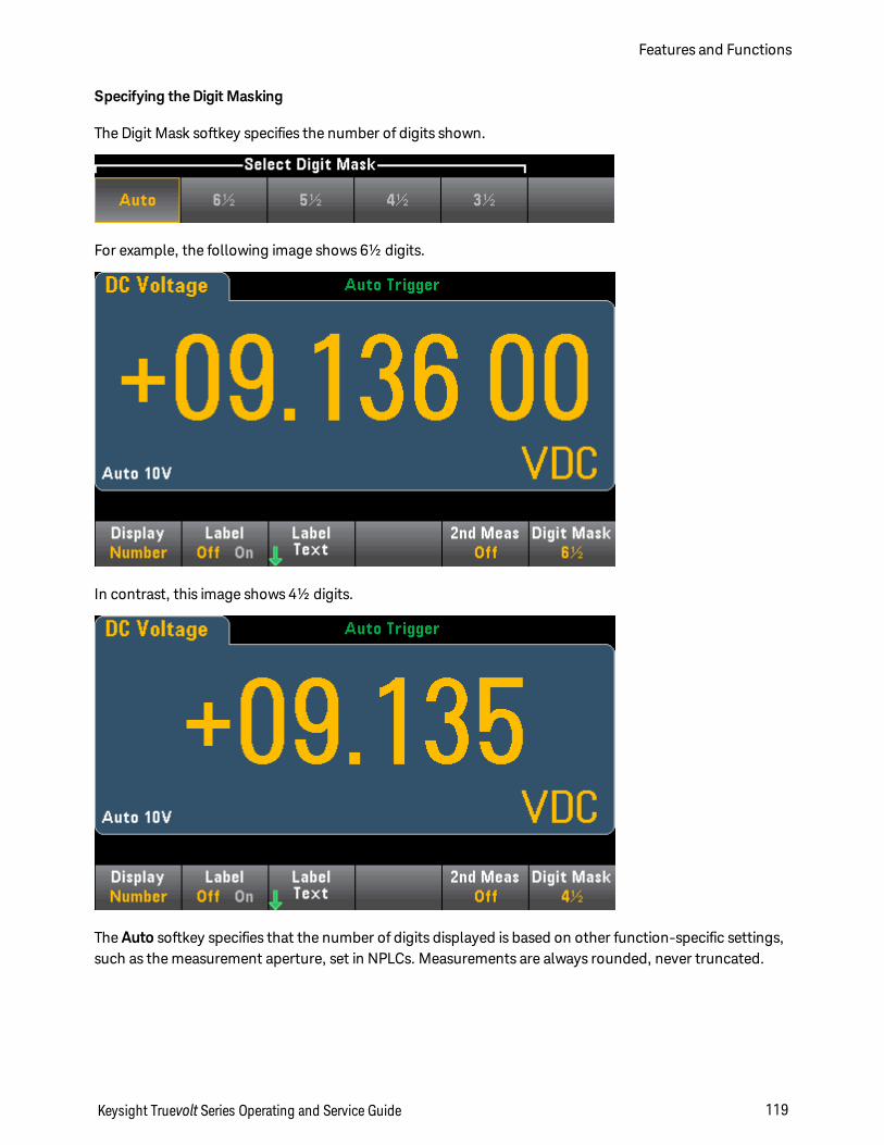
Specifying the Digit Masking
The Digit Mask softkey specifies the number of digits shown.
For example, the following image shows 6½ digits.
In contrast, this image shows 4½ digits.
The Auto softkey specifies that the number of digits displayed is based on other function-specific settings,such as the measurement aperture, set in NPLCs. Measurements are always rounded, never truncated.
Keysight Truevolt Series Operating and Service Guide 119
Features and Functions
See Also
Display - Introduction
Bar Meter
Trend Chart (34461A/65A/70A only)
Histogram
Secondary Measurements
Features and Functions
120 Keysight Truevolt Series Operating and Service Guide
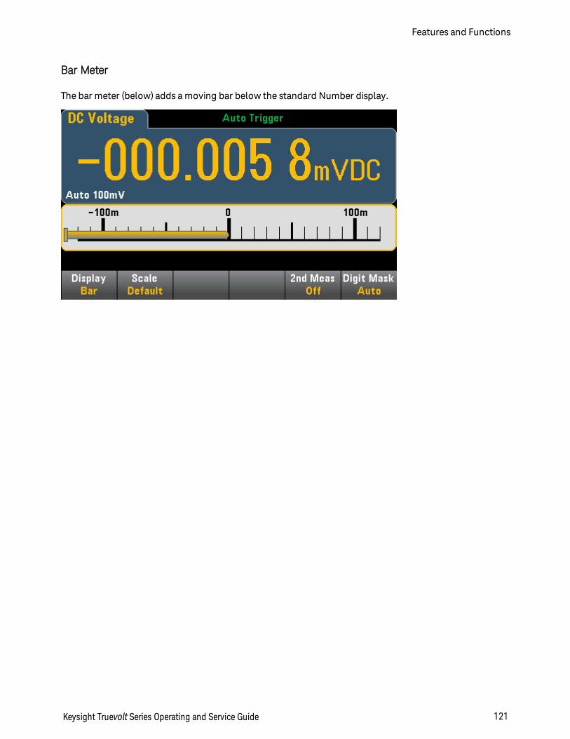
Bar Meter
The bar meter (below) adds a moving bar below the standard Number display.
Keysight Truevolt Series Operating and Service Guide 121
Features and Functions
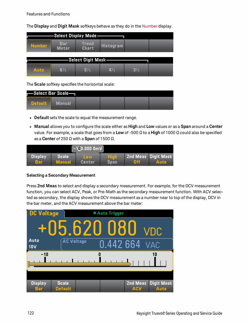
The Display and Digit Mask softkeys behave as they do in the Number display.
The Scale softkey specifies the horizontal scale:
l Default sets the scale to equal the measurement range.
l Manual allows you to configure the scale either as High and Low values or as a Span around a Centervalue. For example, a scale that goes from a Low of -500 Ω to a High of 1000 Ω could also be specifiedas a Center of 250 Ω with a Span of 1500 Ω.
Selecting a Secondary Measurement
Press 2nd Meas to select and display a secondary measurement. For example, for the DCV measurementfunction, you can select ACV, Peak, or Pre-Math as the secondary measurement function. With ACV selec-ted as secondary, the display shows the DCV measurement as a number near to top of the display, DCV inthe bar meter, and the ACV measurement above the bar meter:
Features and Functions
122 Keysight Truevolt Series Operating and Service Guide
Refer to Secondary Measurements for more information on secondary measurements available for eachmeasurement function.
See Also
Display - Introduction
Number
Trend Chart (34461A/65A/70A only)
Histogram
Secondary Measurements
Keysight Truevolt Series Operating and Service Guide 123
Features and Functions
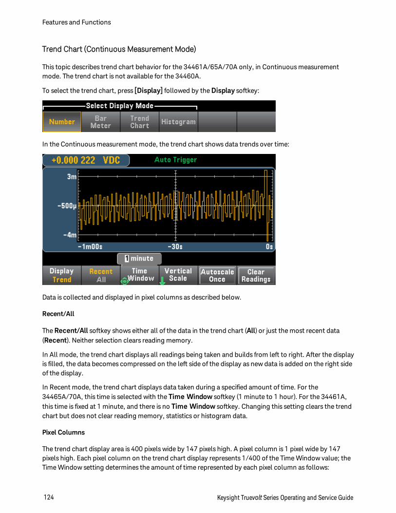
Trend Chart (Continuous Measurement Mode)
This topic describes trend chart behavior for the 34461A/65A/70A only, in Continuous measurementmode. The trend chart is not available for the 34460A.
To select the trend chart, press [Display] followed by the Display softkey:
In the Continuous measurement mode, the trend chart shows data trends over time:
Data is collected and displayed in pixel columns as described below.
Recent/All
The Recent/All softkey shows either all of the data in the trend chart (All) or just the most recent data(Recent). Neither selection clears reading memory.
In All mode, the trend chart displays all readings being taken and builds from left to right. After the displayis filled, the data becomes compressed on the left side of the display as new data is added on the right sideof the display.
In Recent mode, the trend chart displays data taken during a specified amount of time. For the34465A/70A, this time is selected with the Time Window softkey (1 minute to 1 hour). For the 34461A,this time is fixed at 1 minute, and there is no Time Window softkey. Changing this setting clears the trendchart but does not clear reading memory, statistics or histogram data.
Pixel Columns
The trend chart display area is 400 pixels wide by 147 pixels high. A pixel column is 1 pixel wide by 147pixels high. Each pixel column on the trend chart display represents 1/400 of the Time Window value; theTime Window setting determines the amount of time represented by each pixel column as follows:
Features and Functions
124 Keysight Truevolt Series Operating and Service Guide
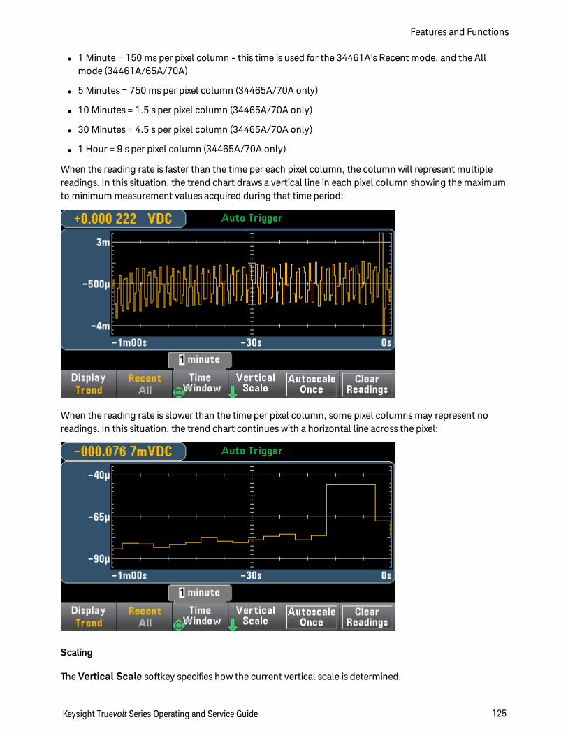
l 1 Minute = 150 ms per pixel column - this time is used for the 34461A's Recent mode, and the Allmode (34461A/65A/70A)
l 5 Minutes = 750 ms per pixel column (34465A/70A only)
l 10 Minutes = 1.5 s per pixel column (34465A/70A only)
l 30 Minutes = 4.5 s per pixel column (34465A/70A only)
l 1 Hour = 9 s per pixel column (34465A/70A only)
When the reading rate is faster than the time per each pixel column, the column will represent multiplereadings. In this situation, the trend chart draws a vertical line in each pixel column showing the maximumto minimum measurement values acquired during that time period:
When the reading rate is slower than the time per pixel column, some pixel columns may represent noreadings. In this situation, the trend chart continues with a horizontal line across the pixel:
Scaling
The Vertical Scale softkey specifies how the current vertical scale is determined.
Keysight Truevolt Series Operating and Service Guide 125
Features and Functions
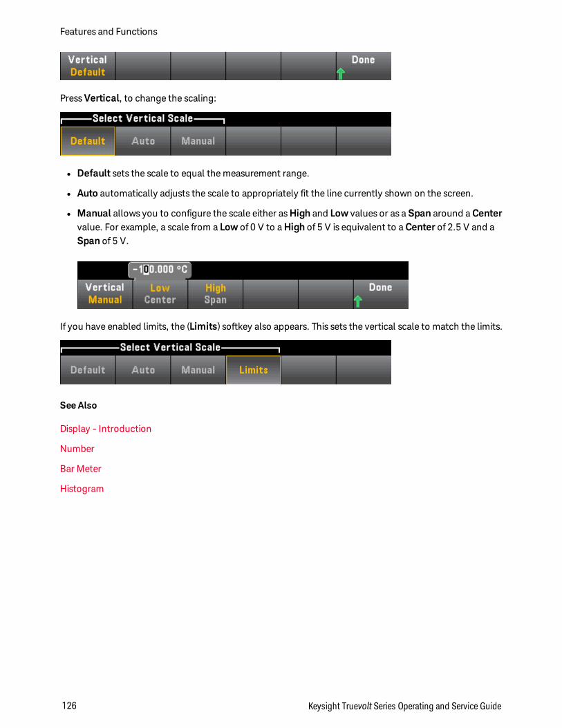
Press Vertical, to change the scaling:
l Default sets the scale to equal the measurement range.
l Auto automatically adjusts the scale to appropriately fit the line currently shown on the screen.
l Manual allows you to configure the scale either as High and Low values or as a Span around a Centervalue. For example, a scale from a Low of 0 V to a High of 5 V is equivalent to a Center of 2.5 V and aSpan of 5 V.
If you have enabled limits, the (Limits) softkey also appears. This sets the vertical scale to match the limits.
See Also
Display - Introduction
Number
Bar Meter
Histogram
Features and Functions
126 Keysight Truevolt Series Operating and Service Guide
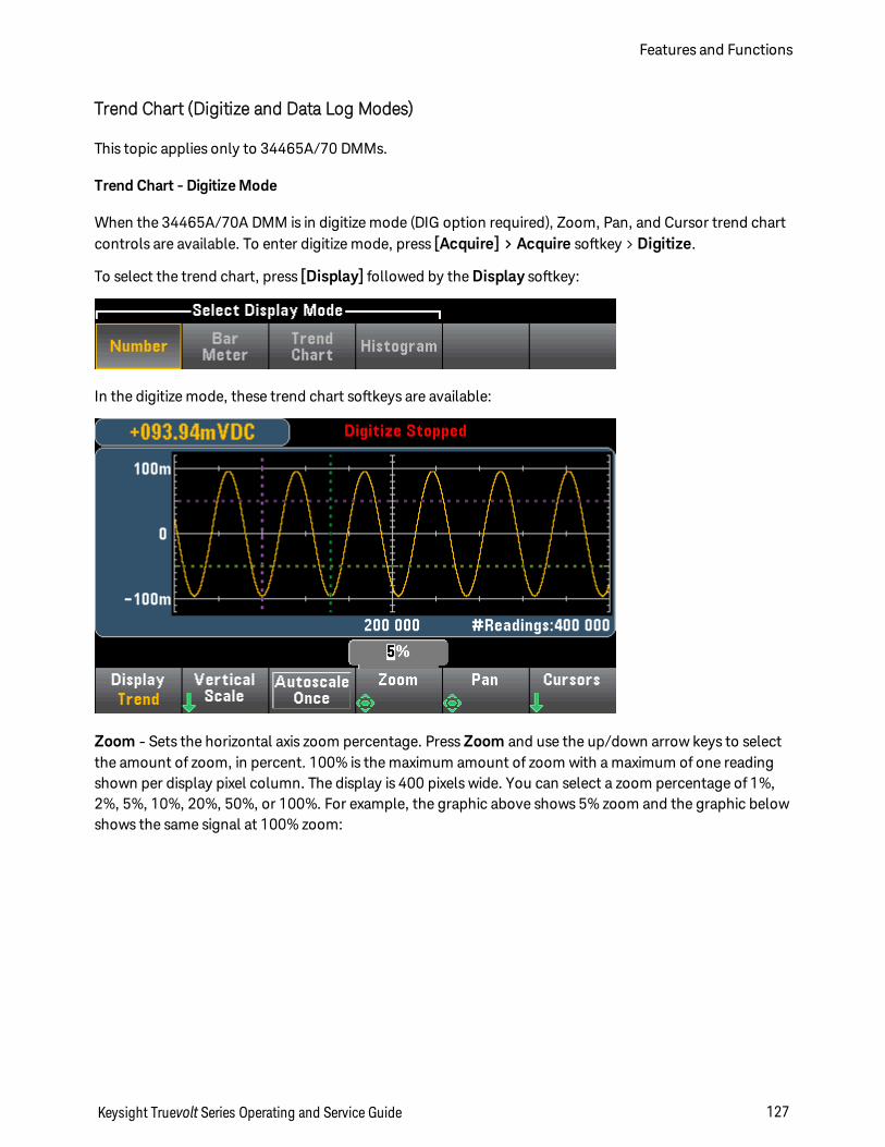
Trend Chart (Digitize and Data Log Modes)
This topic applies only to 34465A/70 DMMs.
Trend Chart - Digitize Mode
When the 34465A/70A DMM is in digitize mode (DIG option required), Zoom, Pan, and Cursor trend chartcontrols are available. To enter digitize mode, press [Acquire] > Acquire softkey > Digitize.
To select the trend chart, press [Display] followed by the Display softkey:
In the digitize mode, these trend chart softkeys are available:
Zoom - Sets the horizontal axis zoom percentage. Press Zoom and use the up/down arrow keys to selectthe amount of zoom, in percent. 100% is the maximum amount of zoom with a maximum of one readingshown per display pixel column. The display is 400 pixels wide. You can select a zoom percentage of 1%,2%, 5%, 10%, 20%, 50%, or 100%. For example, the graphic above shows 5% zoom and the graphic belowshows the same signal at 100% zoom:
Keysight Truevolt Series Operating and Service Guide 127
Features and Functions
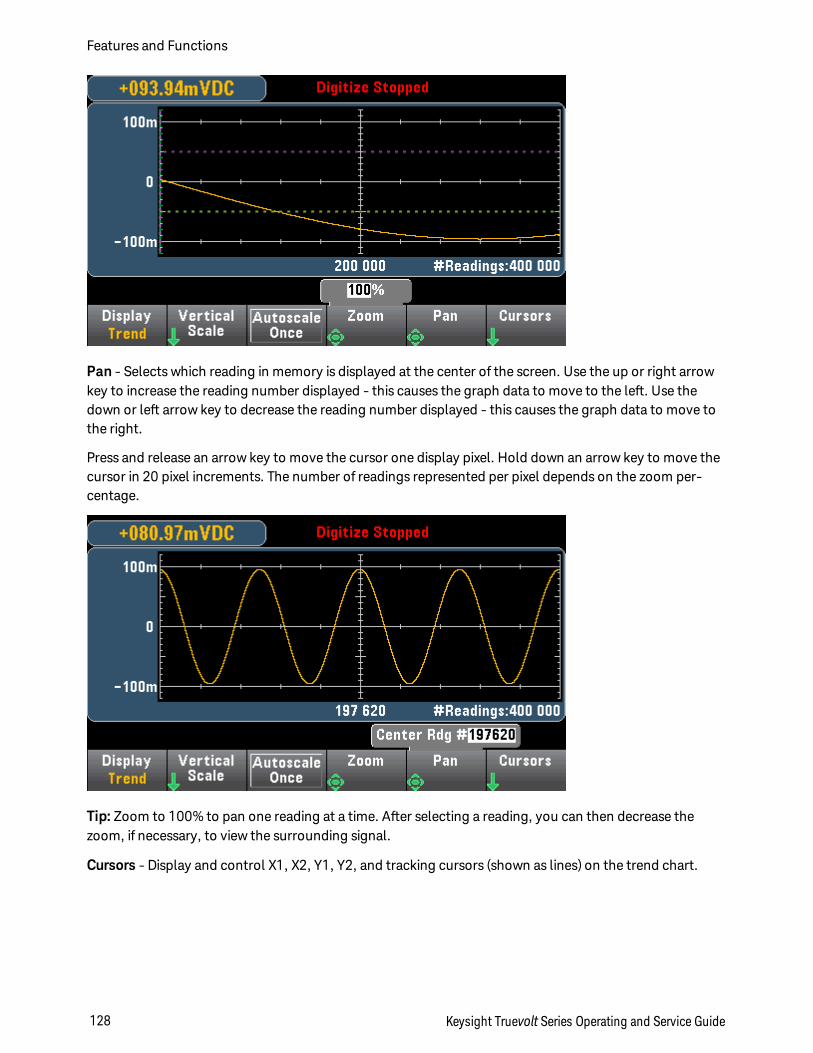
Pan - Selects which reading in memory is displayed at the center of the screen. Use the up or right arrowkey to increase the reading number displayed - this causes the graph data to move to the left. Use thedown or left arrow key to decrease the reading number displayed - this causes the graph data to move tothe right.
Press and release an arrow key to move the cursor one display pixel. Hold down an arrow key to move thecursor in 20 pixel increments. The number of readings represented per pixel depends on the zoom per-centage.
Tip: Zoom to 100% to pan one reading at a time. After selecting a reading, you can then decrease thezoom, if necessary, to view the surrounding signal.
Cursors - Display and control X1, X2, Y1, Y2, and tracking cursors (shown as lines) on the trend chart.
Features and Functions
128 Keysight Truevolt Series Operating and Service Guide
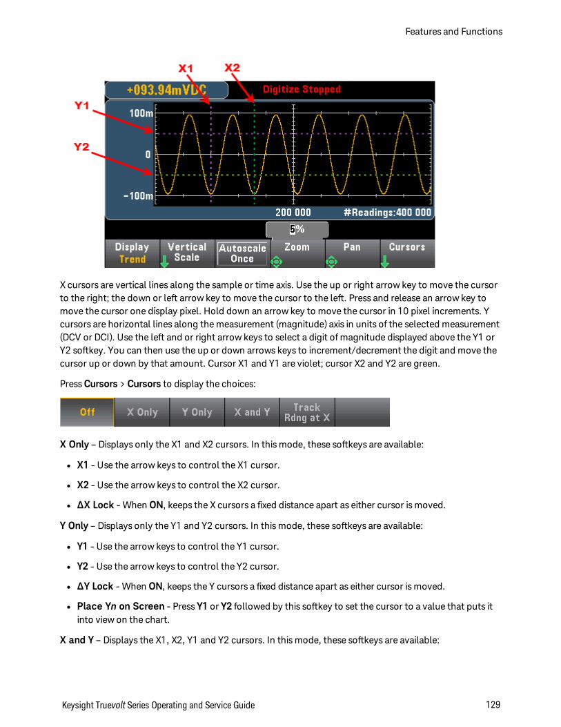
X cursors are vertical lines along the sample or time axis. Use the up or right arrow key to move the cursorto the right; the down or left arrow key to move the cursor to the left. Press and release an arrow key tomove the cursor one display pixel. Hold down an arrow key to move the cursor in 10 pixel increments. Ycursors are horizontal lines along the measurement (magnitude) axis in units of the selected measurement(DCV or DCI). Use the left and or right arrow keys to select a digit of magnitude displayed above the Y1 orY2 softkey. You can then use the up or down arrows keys to increment/decrement the digit and move thecursor up or down by that amount. Cursor X1 and Y1 are violet; cursor X2 and Y2 are green.
Press Cursors > Cursors to display the choices:
X Only – Displays only the X1 and X2 cursors. In this mode, these softkeys are available:
l X1 - Use the arrow keys to control the X1 cursor.
l X2 - Use the arrow keys to control the X2 cursor.
l ∆X Lock - When ON, keeps the X cursors a fixed distance apart as either cursor is moved.
Y Only – Displays only the Y1 and Y2 cursors. In this mode, these softkeys are available:
l Y1 - Use the arrow keys to control the Y1 cursor.
l Y2 - Use the arrow keys to control the Y2 cursor.
l ∆Y Lock - When ON, keeps the Y cursors a fixed distance apart as either cursor is moved.
l Place Yn on Screen - Press Y1 or Y2 followed by this softkey to set the cursor to a value that puts itinto view on the chart.
X and Y – Displays the X1, X2, Y1 and Y2 cursors. In this mode, these softkeys are available:
Keysight Truevolt Series Operating and Service Guide 129
Features and Functions
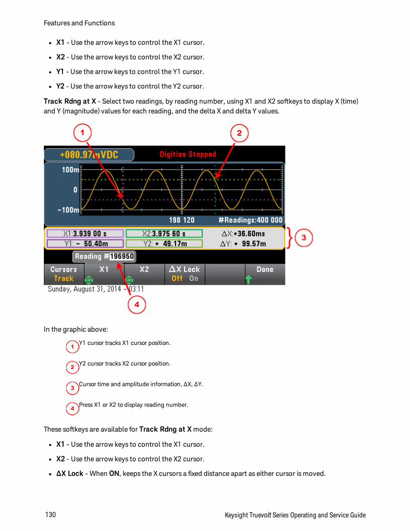
l X1 - Use the arrow keys to control the X1 cursor.
l X2 - Use the arrow keys to control the X2 cursor.
l Y1 - Use the arrow keys to control the Y1 cursor.
l Y2 - Use the arrow keys to control the Y2 cursor.
Track Rdng at X - Select two readings, by reading number, using X1 and X2 softkeys to display X (time)and Y (magnitude) values for each reading, and the delta X and delta Y values.
In the graphic above:
Y1 cursor tracks X1 cursor position.
Y2 cursor tracks X2 cursor position.
Cursor time and amplitude information, ∆X, ∆Y.
Press X1 or X2 to display reading number.
These softkeys are available for Track Rdng at X mode:
l X1 - Use the arrow keys to control the X1 cursor.
l X2 - Use the arrow keys to control the X2 cursor.
l ∆X Lock - When ON, keeps the X cursors a fixed distance apart as either cursor is moved.
Features and Functions
130 Keysight Truevolt Series Operating and Service Guide
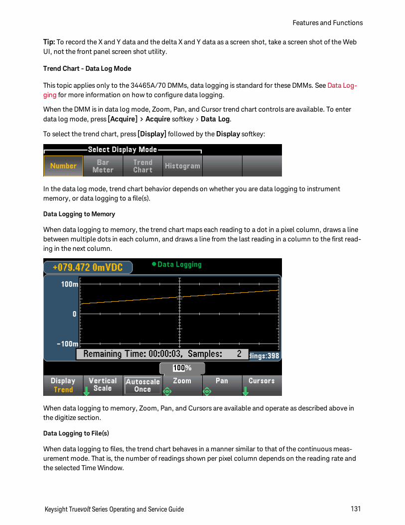
Tip: To record the X and Y data and the delta X and Y data as a screen shot, take a screen shot of the WebUI, not the front panel screen shot utility.
Trend Chart - Data Log Mode
This topic applies only to the 34465A/70 DMMs, data logging is standard for these DMMs. See Data Log-ging for more information on how to configure data logging.
When the DMM is in data log mode, Zoom, Pan, and Cursor trend chart controls are available. To enterdata log mode, press [Acquire] > Acquire softkey > Data Log.
To select the trend chart, press [Display] followed by the Display softkey:
In the data log mode, trend chart behavior depends on whether you are data logging to instrumentmemory, or data logging to a file(s).
Data Logging to Memory
When data logging to memory, the trend chart maps each reading to a dot in a pixel column, draws a linebetween multiple dots in each column, and draws a line from the last reading in a column to the first read-ing in the next column.
When data logging to memory, Zoom, Pan, and Cursors are available and operate as described above inthe digitize section.
Data Logging to File(s)
When data logging to files, the trend chart behaves in a manner similar to that of the continuous meas-urement mode. That is, the number of readings shown per pixel column depends on the reading rate andthe selected Time Window.
Keysight Truevolt Series Operating and Service Guide 131
Features and Functions
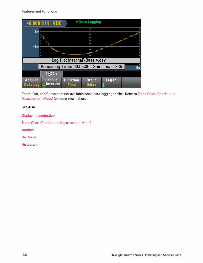
Zoom, Pan, and Cursors are not available when data logging to files. Refer to Trend Chart (ContinuousMeasurement Mode) for more information.
See Also
Display - Introduction
Trend Chart (Continuous Measurement Mode)
Number
Bar Meter
Histogram
Features and Functions
132 Keysight Truevolt Series Operating and Service Guide
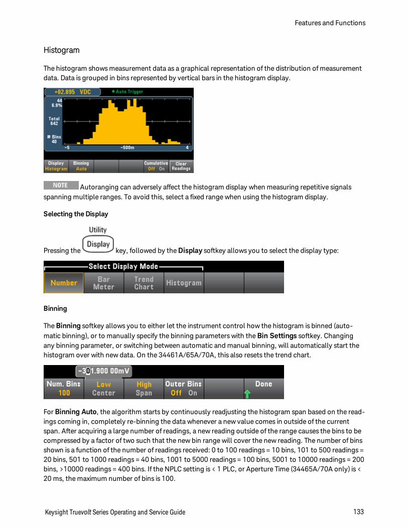
Histogram
The histogram shows measurement data as a graphical representation of the distribution of measurementdata. Data is grouped in bins represented by vertical bars in the histogram display.
Autoranging can adversely affect the histogram display when measuring repetitive signalsspanning multiple ranges. To avoid this, select a fixed range when using the histogram display.
Selecting the Display
Pressing the key, followed by the Display softkey allows you to select the display type:
Binning
The Binning softkey allows you to either let the instrument control how the histogram is binned (auto-matic binning), or to manually specify the binning parameters with the Bin Settings softkey. Changingany binning parameter, or switching between automatic and manual binning, will automatically start thehistogram over with new data. On the 34461A/65A/70A, this also resets the trend chart.
For Binning Auto, the algorithm starts by continuously readjusting the histogram span based on the read-ings coming in, completely re-binning the data whenever a new value comes in outside of the currentspan. After acquiring a large number of readings, a new reading outside of the range causes the bins to becompressed by a factor of two such that the new bin range will cover the new reading. The number of binsshown is a function of the number of readings received: 0 to 100 readings = 10 bins, 101 to 500 readings =20 bins, 501 to 1000 readings = 40 bins, 1001 to 5000 readings = 100 bins, 5001 to 10000 readings = 200bins, >10000 readings = 400 bins. If the NPLC setting is < 1 PLC, or Aperture Time (34465A/70A only) is <20 ms, the maximum number of bins is 100.
Keysight Truevolt Series Operating and Service Guide 133
Features and Functions
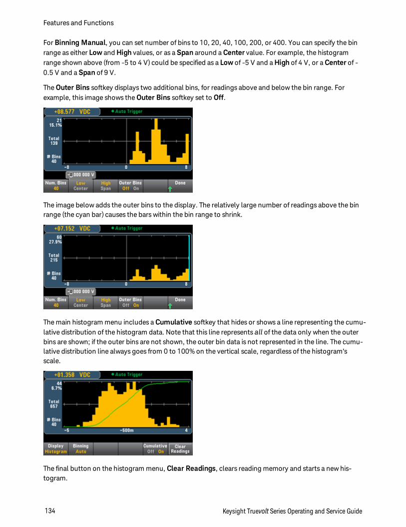
For Binning Manual, you can set number of bins to 10, 20, 40, 100, 200, or 400. You can specify the binrange as either Low and High values, or as a Span around a Center value. For example, the histogramrange shown above (from -5 to 4 V) could be specified as a Low of -5 V and a High of 4 V, or a Center of -0.5 V and a Span of 9 V.
The Outer Bins softkey displays two additional bins, for readings above and below the bin range. Forexample, this image shows the Outer Bins softkey set to Off.
The image below adds the outer bins to the display. The relatively large number of readings above the binrange (the cyan bar) causes the bars within the bin range to shrink.
The main histogram menu includes a Cumulative softkey that hides or shows a line representing the cumu-lative distribution of the histogram data. Note that this line represents all of the data only when the outerbins are shown; if the outer bins are not shown, the outer bin data is not represented in the line. The cumu-lative distribution line always goes from 0 to 100% on the vertical scale, regardless of the histogram’sscale.
The final button on the histogram menu, Clear Readings, clears reading memory and starts a new his-togram.
Features and Functions
134 Keysight Truevolt Series Operating and Service Guide
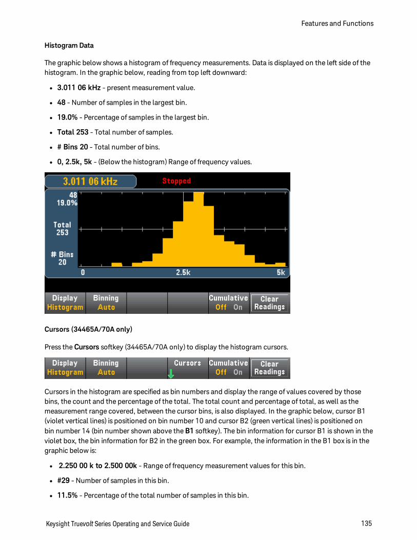
Histogram Data
The graphic below shows a histogram of frequency measurements. Data is displayed on the left side of thehistogram. In the graphic below, reading from top left downward:
l 3.011 06 kHz - present measurement value.
l 48 - Number of samples in the largest bin.
l 19.0% - Percentage of samples in the largest bin.
l Total 253 - Total number of samples.
l # Bins 20 - Total number of bins.
l 0, 2.5k, 5k - (Below the histogram) Range of frequency values.
Cursors (34465A/70A only)
Press the Cursors softkey (34465A/70A only) to display the histogram cursors.
Cursors in the histogram are specified as bin numbers and display the range of values covered by thosebins, the count and the percentage of the total. The total count and percentage of total, as well as themeasurement range covered, between the cursor bins, is also displayed. In the graphic below, cursor B1(violet vertical lines) is positioned on bin number 10 and cursor B2 (green vertical lines) is positioned onbin number 14 (bin number shown above the B1 softkey). The bin information for cursor B1 is shown in theviolet box, the bin information for B2 in the green box. For example, the information in the B1 box is in thegraphic below is:
l 2.250 00 k to 2.500 00k - Range of frequency measurement values for this bin.
l #29 - Number of samples in this bin.
l 11.5% - Percentage of the total number of samples in this bin.
Keysight Truevolt Series Operating and Service Guide 135
Features and Functions
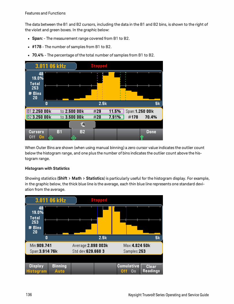
The data between the B1 and B2 cursors, including the data in the B1 and B2 bins, is shown to the right ofthe violet and green boxes. In the graphic below:
l Span: - The measurement range covered from B1 to B2.
l #178 - The number of samples from B1 to B2.
l 70.4% - The percentage of the total number of samples from B1 to B2.
When Outer Bins are shown (when using manual binning) a zero cursor value indicates the outlier countbelow the histogram range, and one plus the number of bins indicates the outlier count above the his-togram range.
Histogram with Statistics
Showing statistics (Shift > Math > Statistics) is particularly useful for the histogram display. For example,in the graphic below, the thick blue line is the average, each thin blue line represents one standard devi-ation from the average.
Features and Functions
136 Keysight Truevolt Series Operating and Service Guide

See Also
Display - Introduction
Number
Bar Meter
Trend Chart (34461A/65A/70A only)
Keysight Truevolt Series Operating and Service Guide 137
Features and Functions
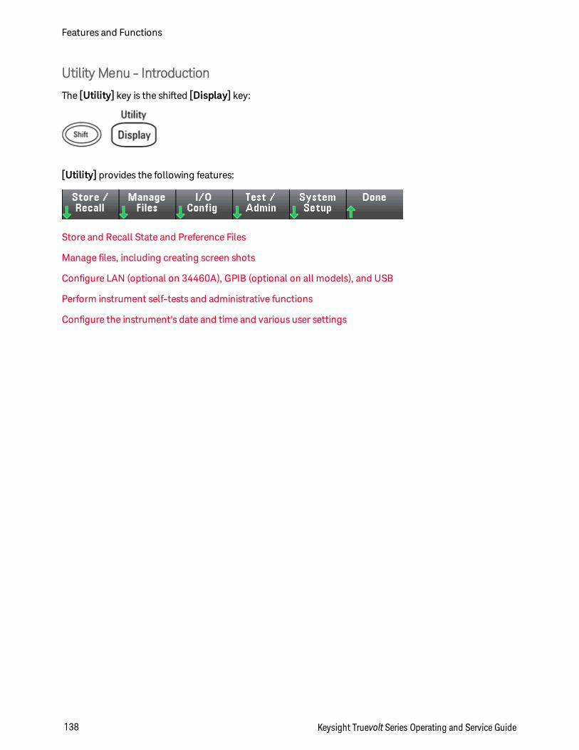
Utility Menu - Introduction
The [Utility] key is the shifted [Display] key:
[Utility] provides the following features:
Store and Recall State and Preference Files
Manage files, including creating screen shots
Configure LAN (optional on 34460A), GPIB (optional on all models), and USB
Perform instrument self-tests and administrative functions
Configure the instrument's date and time and various user settings
Features and Functions
138 Keysight Truevolt Series Operating and Service Guide
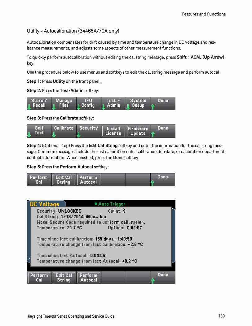
Utility - Autocalibration (34465A/70A only)
Autocalibration compensates for drift caused by time and temperature change in DC voltage and res-istance measurements, and adjusts some aspects of other measurement functions.
To quickly perform autocalibration without editing the cal string message, press Shift > ACAL (Up Arrow)key.
Use the procedure below to use menus and softkeys to edit the cal string message and perform autocal
Step 1: Press Utility on the front panel.
Step 2: Press the Test/Admin softkey:
Step 3: Press the Calibrate softkey:
Step 4: (Optional step) Press the Edit Cal String softkey and enter the information for the cal string mes-sage. Common messages include the last calibration date, calibration due date, or calibration departmentcontact information. When finished, press the Done softkey
Step 5: Press the Perform Autocal softkey:
Keysight Truevolt Series Operating and Service Guide 139
Features and Functions
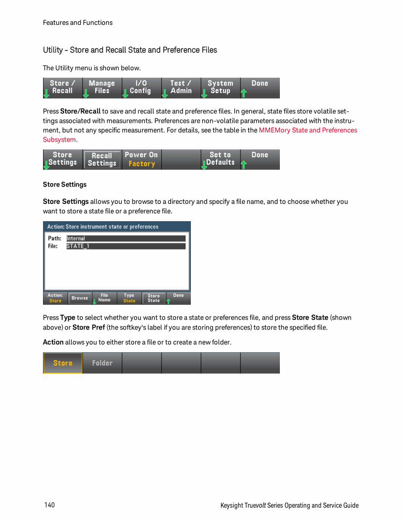
Utility - Store and Recall State and Preference Files
The Utility menu is shown below.
Press Store/Recall to save and recall state and preference files. In general, state files store volatile set-tings associated with measurements. Preferences are non-volatile parameters associated with the instru-ment, but not any specific measurement. For details, see the table in the MMEMory State and PreferencesSubsystem.
Store Settings
Store Settings allows you to browse to a directory and specify a file name, and to choose whether youwant to store a state file or a preference file.
Press Type to select whether you want to store a state or preferences file, and press Store State (shownabove) or Store Pref (the softkey's label if you are storing preferences) to store the specified file.
Action allows you to either store a file or to create a new folder.
Features and Functions
140 Keysight Truevolt Series Operating and Service Guide
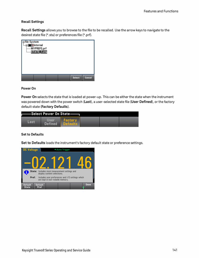
Recall Settings
Recall Settings allows you to browse to the file to be recalled. Use the arrow keys to navigate to thedesired state file (*.sta) or preferences file (*.prf).
Power On
Power On selects the state that is loaded at power-up. This can be either the state when the instrumentwas powered down with the power switch (Last), a user-selected state file (User Defined), or the factorydefault state (Factory Defaults).
Set to Defaults
Set to Defaults loads the instrument's factory default state or preference settings.
Keysight Truevolt Series Operating and Service Guide 141
Features and Functions
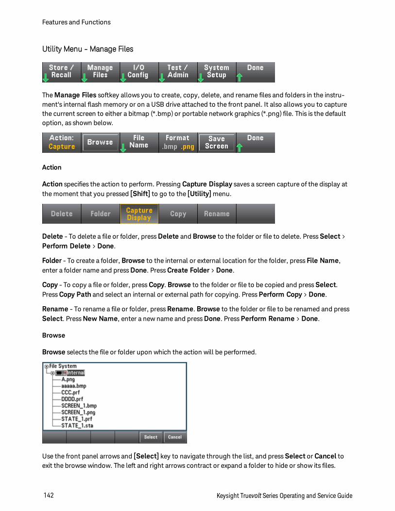
Utility Menu - Manage Files
The Manage Files softkey allows you to create, copy, delete, and rename files and folders in the instru-ment's internal flash memory or on a USB drive attached to the front panel. It also allows you to capturethe current screen to either a bitmap (*.bmp) or portable network graphics (*.png) file. This is the defaultoption, as shown below.
Action
Action specifies the action to perform. Pressing Capture Display saves a screen capture of the display atthe moment that you pressed [Shift] to go to the [Utility] menu.
Delete - To delete a file or folder, press Delete and Browse to the folder or file to delete. Press Select >Perform Delete > Done.
Folder - To create a folder, Browse to the internal or external location for the folder, press File Name,enter a folder name and press Done. Press Create Folder > Done.
Copy - To copy a file or folder, press Copy. Browse to the folder or file to be copied and press Select.Press Copy Path and select an internal or external path for copying. Press Perform Copy > Done.
Rename - To rename a file or folder, press Rename. Browse to the folder or file to be renamed and pressSelect. Press New Name, enter a new name and press Done. Press Perform Rename > Done.
Browse
Browse selects the file or folder upon which the action will be performed.
Use the front panel arrows and [Select] key to navigate through the list, and press Select or Cancel toexit the browse window. The left and right arrows contract or expand a folder to hide or show its files.
Features and Functions
142 Keysight Truevolt Series Operating and Service Guide
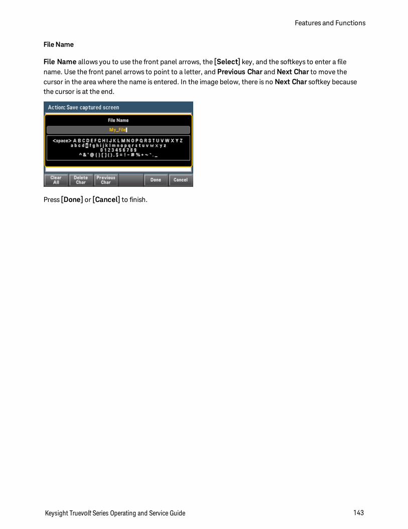
File Name
File Name allows you to use the front panel arrows, the [Select] key, and the softkeys to enter a filename. Use the front panel arrows to point to a letter, and Previous Char and Next Char to move thecursor in the area where the name is entered. In the image below, there is no Next Char softkey becausethe cursor is at the end.
Press [Done] or [Cancel] to finish.
Keysight Truevolt Series Operating and Service Guide 143
Features and Functions
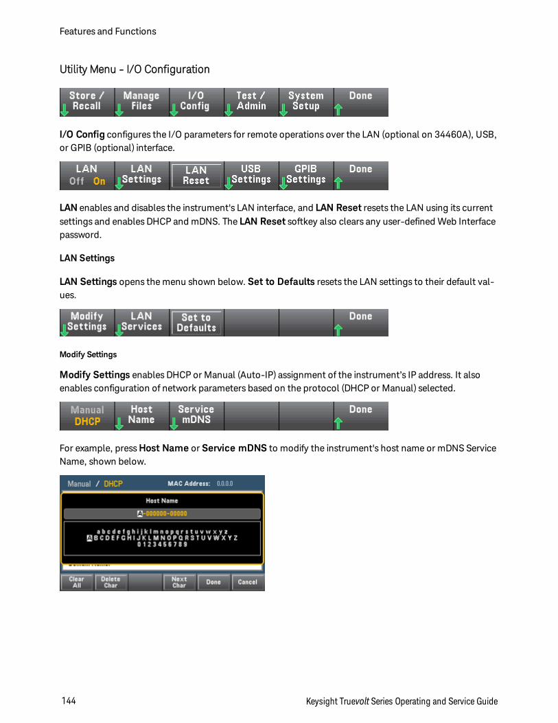
Utility Menu - I/O Configuration
I/O Config configures the I/O parameters for remote operations over the LAN (optional on 34460A), USB,or GPIB (optional) interface.
LAN enables and disables the instrument's LAN interface, and LAN Reset resets the LAN using its currentsettings and enables DHCP and mDNS. The LAN Reset softkey also clears any user-defined Web Interfacepassword.
LAN Settings
LAN Settings opens the menu shown below. Set to Defaults resets the LAN settings to their default val-ues.
Modify Settings
Modify Settings enables DHCP or Manual (Auto-IP) assignment of the instrument’s IP address. It alsoenables configuration of network parameters based on the protocol (DHCP or Manual) selected.
For example, press Host Name or Service mDNS to modify the instrument's host name or mDNS ServiceName, shown below.
Features and Functions
144 Keysight Truevolt Series Operating and Service Guide
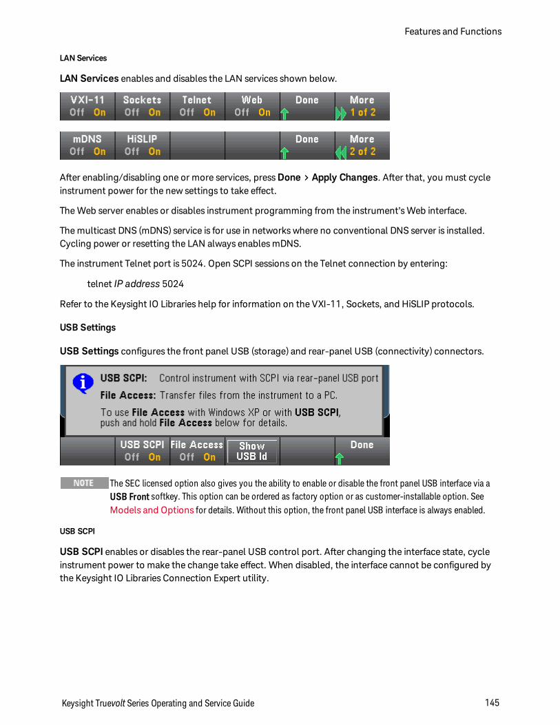
LAN Services
LAN Services enables and disables the LAN services shown below.
After enabling/disabling one or more services, press Done > Apply Changes. After that, you must cycleinstrument power for the new settings to take effect.
The Web server enables or disables instrument programming from the instrument’s Web interface.
The multicast DNS (mDNS) service is for use in networks where no conventional DNS server is installed.Cycling power or resetting the LAN always enables mDNS.
The instrument Telnet port is 5024. Open SCPI sessions on the Telnet connection by entering:
telnet IP address 5024
Refer to the Keysight IO Libraries help for information on the VXI-11, Sockets, and HiSLIP protocols.
USB Settings
USB Settings configures the front panel USB (storage) and rear-panel USB (connectivity) connectors.
The SEC licensed option also gives you the ability to enable or disable the front panel USB interface via aUSB Front softkey. This option can be ordered as factory option or as customer-installable option. SeeModels and Options for details. Without this option, the front panel USB interface is always enabled.
USB SCPI
USB SCPI enables or disables the rear-panel USB control port. After changing the interface state, cycleinstrument power to make the change take effect. When disabled, the interface cannot be configured bythe Keysight IO Libraries Connection Expert utility.
Keysight Truevolt Series Operating and Service Guide 145
Features and Functions
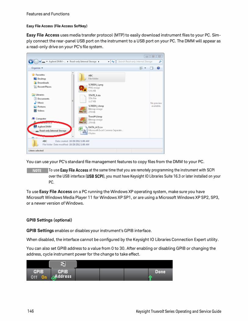
Easy File Access (File Access Softkey)
Easy File Access uses media transfer protocol (MTP) to easily download instrument files to your PC. Sim-ply connect the rear-panel USB port on the instrument to a USB port on your PC. The DMM will appear asa read-only drive on your PC's file system.
You can use your PC's standard file management features to copy files from the DMM to your PC.
To use Easy File Access at the same time that you are remotely programming the instrument with SCPI over the USB interface (USB SCPI), you must have Keysight IO Libraries Suite 16.3 or later installed on your PC.
To use Easy File Access on a PC running the Windows XP operating system, make sure you have Microsoft Windows Media Player 11 for Windows XP SP1, or are using a Microsoft Windows XP SP2, SP3, or a newer version of Windows.
GPIB Settings (optional)
GPIB Settings enables or disables your instrument's GPIB interface.
When disabled, the interface cannot be configured by the Keysight IO Libraries Connection Expert utility.
You can also set GPIB address to a value from 0 to 30. After enabling or disabling GPIB or changing theaddress, cycle instrument power for the change to take effect.
Features and Functions
146 Keysight Truevolt Series Operating and Service Guide
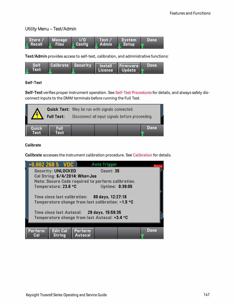
Utility Menu - Test/Admin
Test/Admin provides access to self-test, calibration, and administrative functions:
Self-Test
Self-Test verifies proper instrument operation. See Self-Test Procedures for details, and always safely dis-connect inputs to the DMM terminals before running the Full Test.
Calibrate
Calibrate accesses the instrument calibration procedure. See Calibration for details.
Keysight Truevolt Series Operating and Service Guide 147
Features and Functions
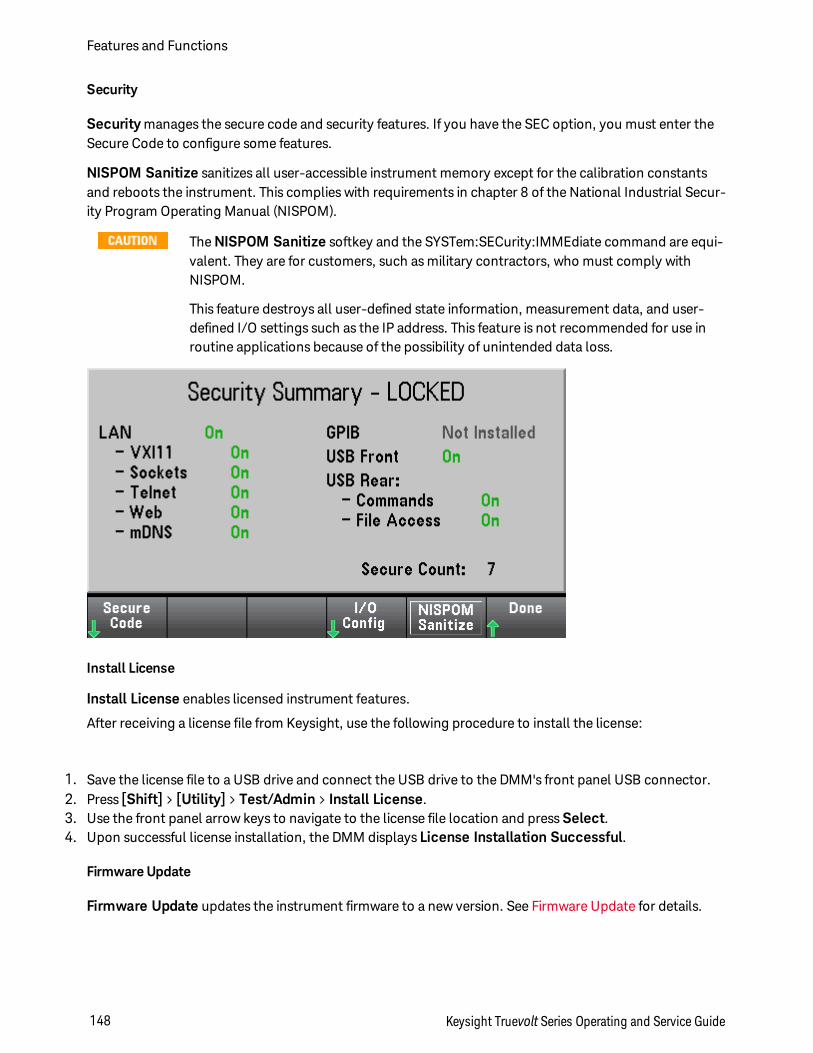
Security
Security manages the secure code and security features. If you have the SEC option, you must enter theSecure Code to configure some features.
NISPOM Sanitize sanitizes all user-accessible instrument memory except for the calibration constantsand reboots the instrument. This complies with requirements in chapter 8 of the National Industrial Secur-ity Program Operating Manual (NISPOM).
The NISPOM Sanitize softkey and the SYSTem:SECurity:IMMEdiate command are equi-valent. They are for customers, such as military contractors, who must comply withNISPOM.
This feature destroys all user-defined state information, measurement data, and user-defined I/O settings such as the IP address. This feature is not recommended for use inroutine applications because of the possibility of unintended data loss.
Install License
Install License enables licensed instrument features.
After receiving a license file from Keysight, use the following procedure to install the license:
1. Save the license file to a USB drive and connect the USB drive to the DMM's front panel USB connector.2. Press [Shift] > [Utility] > Test/Admin > Install License.3. Use the front panel arrow keys to navigate to the license file location and press Select.4. Upon successful license installation, the DMM displays License Installation Successful.
Firmware Update
Firmware Update updates the instrument firmware to a new version. See Firmware Update for details.
Features and Functions
148 Keysight Truevolt Series Operating and Service Guide
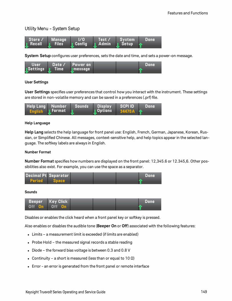
Utility Menu - System Setup
System Setup configures user preferences, sets the date and time, and sets a power-on message.
User Settings
User Settings specifies user preferences that control how you interact with the instrument. These settingsare stored in non-volatile memory and can be saved in a preferences (.prf) file.
Help Language
Help Lang selects the help language for front panel use: English, French, German, Japanese, Korean, Rus-sian, or Simplified Chinese. All messages, context-sensitive help, and help topics appear in the selected lan-guage. The softkey labels are always in English.
Number Format
Number Format specifies how numbers are displayed on the front panel: 12,345.6 or 12.345,6. Other pos-sibilities also exist. For example, you can use the space as a separator.
Sounds
Disables or enables the click heard when a front panel key or softkey is pressed.
Also enables or disables the audible tone (Beeper On or Off) associated with the following features:
l Limits – a measurement limit is exceeded (if limits are enabled)
l Probe Hold – the measured signal records a stable reading
l Diode – the forward bias voltage is between 0.3 and 0.8 V
l Continuity – a short is measured (less than or equal to 10 Ω)
l Error - an error is generated from the front panel or remote interface
Keysight Truevolt Series Operating and Service Guide 149
Features and Functions
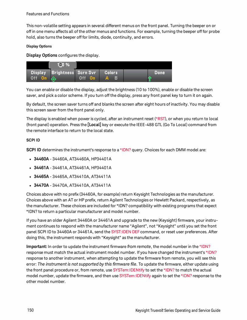
This non-volatile setting appears in several different menus on the front panel. Turning the beeper on oroff in one menu affects all of the other menus and functions. For example, turning the beeper off for probehold, also turns the beeper off for limits, diode, continuity, and errors.
Display Options
Display Options configures the display.
You can enable or disable the display, adjust the brightness (10 to 100%), enable or disable the screensaver, and pick a color scheme. If you turn off the display, press any front panel key to turn it on again.
By default, the screen saver turns off and blanks the screen after eight hours of inactivity. You may disablethis screen saver from the front panel only.
The display is enabled when power is cycled, after an instrument reset (*RST), or when you return to local(front panel) operation. Press the [Local] key or execute the IEEE-488 GTL (Go To Local) command fromthe remote interface to return to the local state.
SCPI ID
SCPI ID determines the instrument's response to a *IDN? query. Choices for each DMM model are:
l 34460A - 34460A, AT34460A, HP34401A
l 34461A - 34461A, AT34461A, HP34401A
l 34465A - 34465A, AT34410A, AT34411A
l 34470A - 34470A, AT34410A, AT34411A
Choices above with no prefix (34460A, for example) return Keysight Technologies as the manufacturer.Choices above with an AT or HP prefix, return Agilent Technologies or Hewlett Packard, respectively, asthe manufacturer. These choices are included for *IDN? compatibility with existing programs that expect*IDN? to return a particular manufacturer and model number.
If you have an older Agilent 34460A or 34461A and upgrade to the new (Keysight) firmware, your instru-ment continues to respond with the manufacturer name “Agilent”, not “Keysight” until you set the frontpanel SCPI ID to 34460A or 34461A, send the SYST:IDEN DEF command, or reset user preferences. Afterdoing this, the instrument responds with “Keysight” as the manufacturer.
Important: In order to update the instrument firmware from remote, the model number in the *IDN?response must match the actual instrument model number. If you have changed the instrument's *IDN?response to another instrument, when attempting to update the firmware from remote, you will see thiserror: The instrument is not supported by this firmware file. To update the firmware, either update usingthe front panel procedure or, from remote, use SYSTem:IDENtify to set the *IDN? to match the actualmodel number, update the firmware, and then use SYSTem:IDENtify again to set the *IDN? response to theother model number.
Features and Functions
150 Keysight Truevolt Series Operating and Service Guide
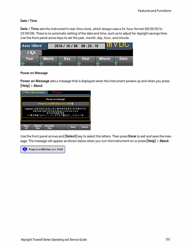
Date / Time
Date / Time sets the instrument's real-time clock, which always uses a 24-hour format (00:00:00 to23:59:59). There is no automatic setting of the date and time, such as to adjust for daylight savings time.Use the front panel arrow keys to set the year, month, day, hour, and minute.
Power on Message
Power on Message sets a message that is displayed when the instrument powers up and when you press[Help] > About.
Use the front panel arrows and [Select] key to select the letters. Then press Done to exit and save the mes-sage. The message will appear as shown below when you turn the instrument on or press [Help] > About.
Keysight Truevolt Series Operating and Service Guide 151
Features and Functions
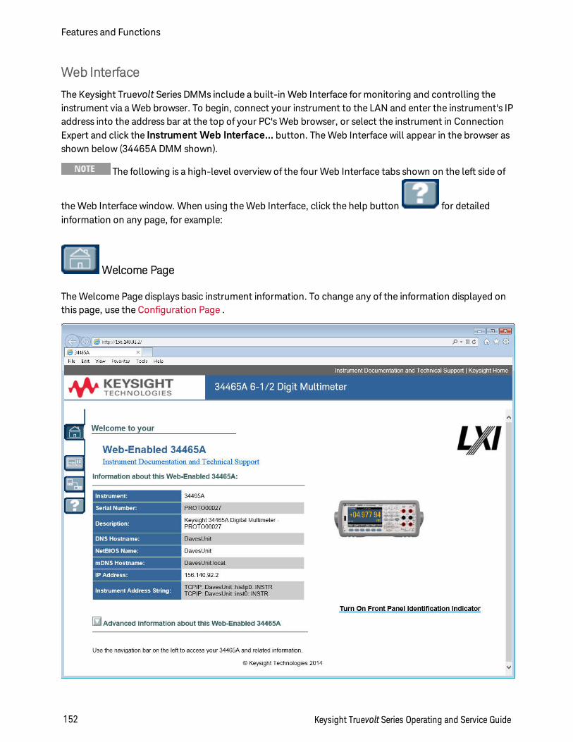
Web Interface
The Keysight Truevolt Series DMMs include a built-in Web Interface for monitoring and controlling theinstrument via a Web browser. To begin, connect your instrument to the LAN and enter the instrument's IPaddress into the address bar at the top of your PC's Web browser, or select the instrument in ConnectionExpert and click the Instrument Web Interface... button. The Web Interface will appear in the browser asshown below (34465A DMM shown).
The following is a high-level overview of the four Web Interface tabs shown on the left side of
the Web Interface window. When using the Web Interface, click the help button for detailedinformation on any page, for example:
Welcome Page
The Welcome Page displays basic instrument information. To change any of the information displayed onthis page, use the Configuration Page .
Features and Functions
152 Keysight Truevolt Series Operating and Service Guide
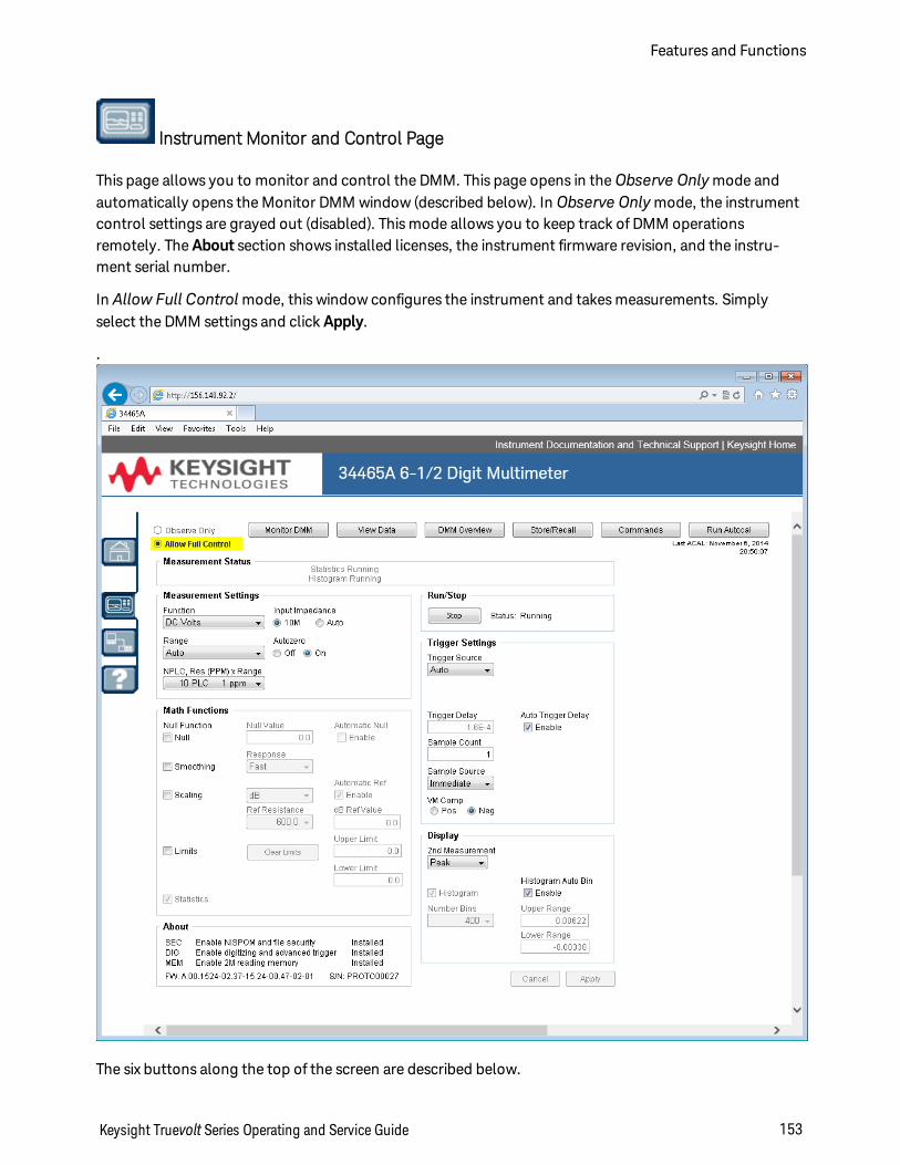
Instrument Monitor and Control Page
This page allows you to monitor and control the DMM. This page opens in theObserve Onlymode andautomatically opens the Monitor DMM window (described below). In Observe Onlymode, the instrumentcontrol settings are grayed out (disabled). This mode allows you to keep track of DMM operationsremotely. The About section shows installed licenses, the instrument firmware revision, and the instru-ment serial number.
In Allow Full Control mode, this window configures the instrument and takes measurements. Simplyselect the DMM settings and click Apply.
.
The six buttons along the top of the screen are described below.
Keysight Truevolt Series Operating and Service Guide 153
Features and Functions
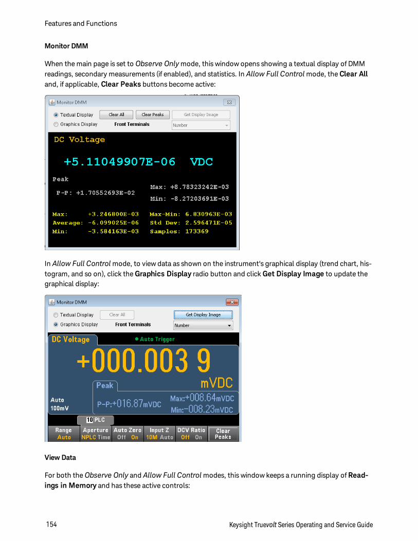
Monitor DMM
When the main page is set to Observe Onlymode, this window opens showing a textual display of DMMreadings, secondary measurements (if enabled), and statistics. In Allow Full Control mode, the Clear Alland, if applicable, Clear Peaks buttons become active:
In Allow Full Control mode, to view data as shown on the instrument's graphical display (trend chart, his-togram, and so on), click the Graphics Display radio button and click Get Display Image to update thegraphical display:
View Data
For both theObserve Only and Allow Full Control modes, this window keeps a running display of Read-ings in Memory and has these active controls:
Features and Functions
154 Keysight Truevolt Series Operating and Service Guide
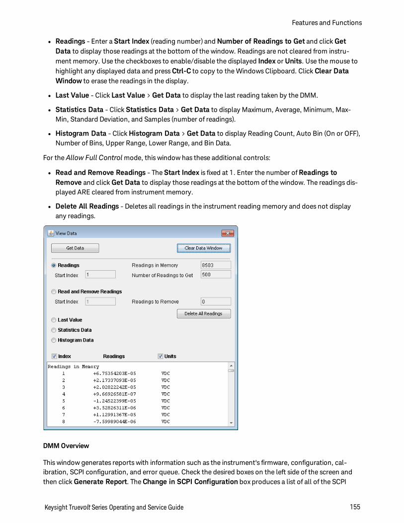
l Readings - Enter a Start Index (reading number) and Number of Readings to Get and click GetData to display those readings at the bottom of the window. Readings are not cleared from instru-ment memory. Use the checkboxes to enable/disable the displayed Index or Units. Use the mouse tohighlight any displayed data and press Ctrl-C to copy to the Windows Clipboard. Click Clear DataWindow to erase the readings in the display.
l Last Value - Click Last Value > Get Data to display the last reading taken by the DMM.
l Statistics Data - Click Statistics Data > Get Data to display Maximum, Average, Minimum, Max-Min, Standard Deviation, and Samples (number of readings).
l Histogram Data - Click Histogram Data > Get Data to display Reading Count, Auto Bin (On or OFF),Number of Bins, Upper Range, Lower Range, and Bin Data.
For the Allow Full Control mode, this window has these additional controls:
l Read and Remove Readings - The Start Index is fixed at 1. Enter the number of Readings toRemove and click Get Data to display those readings at the bottom of the window. The readings dis-played ARE cleared from instrument memory.
l Delete All Readings - Deletes all readings in the instrument reading memory and does not displayany readings.
DMM Overview
This window generates reports with information such as the instrument's firmware, configuration, cal-ibration, SCPI configuration, and error queue. Check the desired boxes on the left side of the screen andthen click Generate Report. The Change in SCPI Configuration box produces a list of all of the SCPI
Keysight Truevolt Series Operating and Service Guide 155
Features and Functions
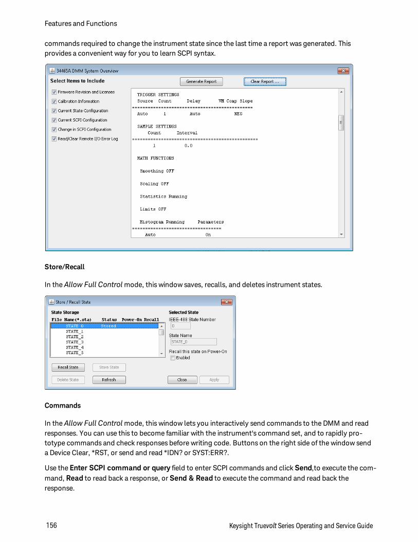
commands required to change the instrument state since the last time a report was generated. Thisprovides a convenient way for you to learn SCPI syntax.
Store/Recall
In theAllow Full Control mode, this window saves, recalls, and deletes instrument states.
Commands
In theAllow Full Control mode, this window lets you interactively send commands to the DMM and readresponses. You can use this to become familiar with the instrument's command set, and to rapidly pro-totype commands and check responses before writing code. Buttons on the right side of the window senda Device Clear, *RST, or send and read *IDN? or SYST:ERR?.
Use the Enter SCPI command or query field to enter SCPI commands and click Send,to execute the com-mand, Read to read back a response, or Send & Read to execute the command and read back theresponse.
Features and Functions
156 Keysight Truevolt Series Operating and Service Guide
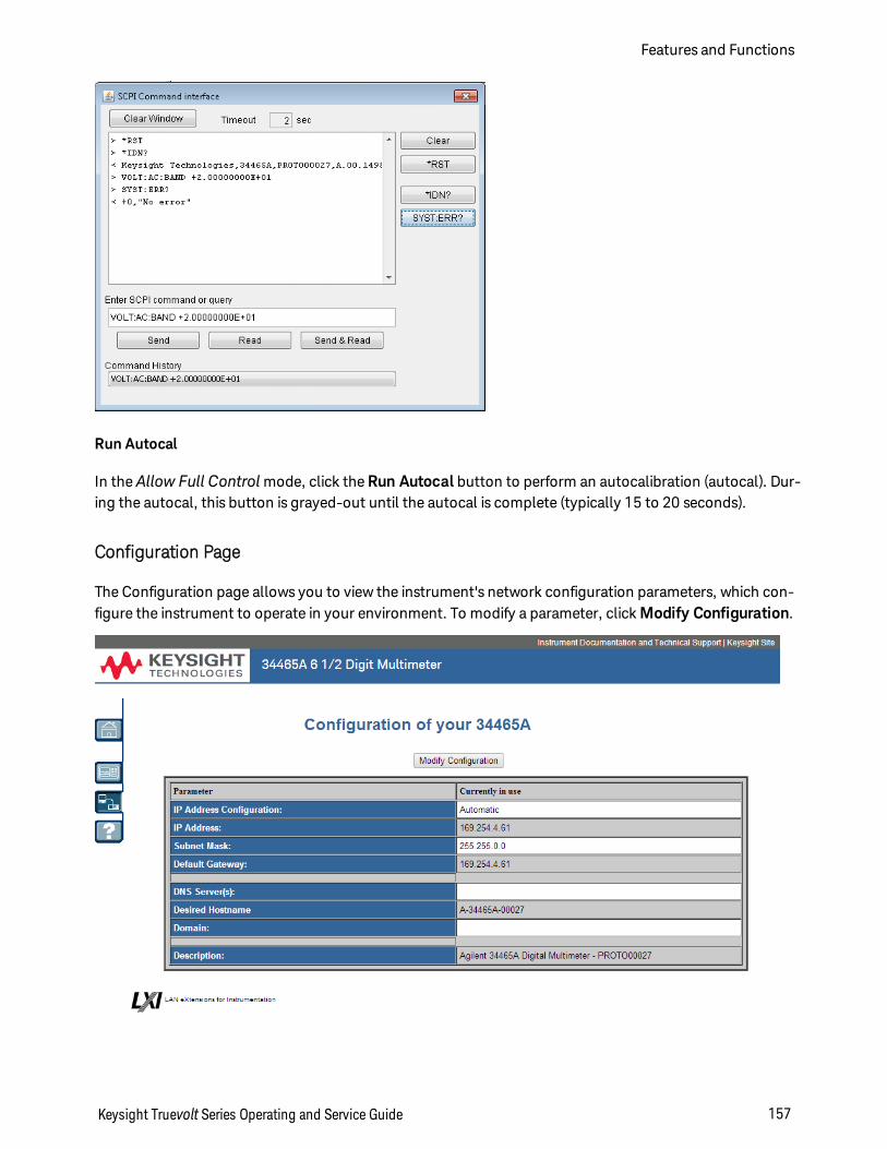
Run Autocal
In theAllow Full Control mode, click the Run Autocal button to perform an autocalibration (autocal). Dur-ing the autocal, this button is grayed-out until the autocal is complete (typically 15 to 20 seconds).
Configuration Page
The Configuration page allows you to view the instrument's network configuration parameters, which con-figure the instrument to operate in your environment. To modify a parameter, click Modify Configuration.
Keysight Truevolt Series Operating and Service Guide 157
Features and Functions
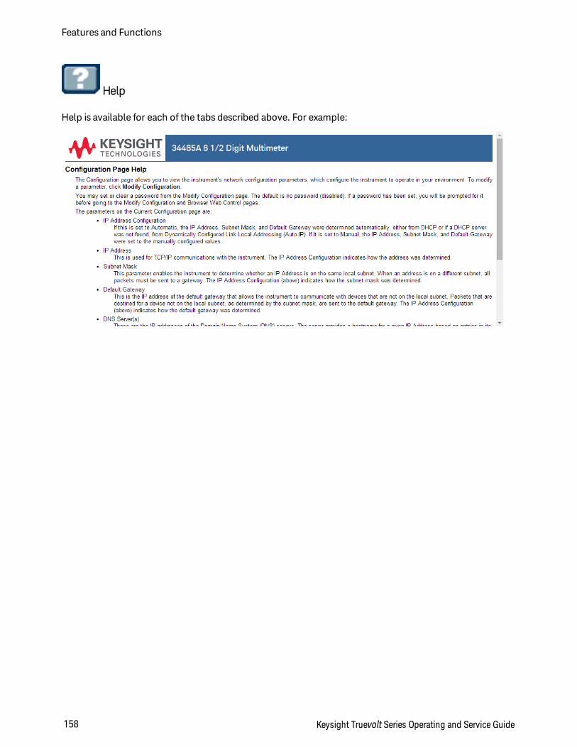
Help
Help is available for each of the tabs described above. For example:
Features and Functions
158 Keysight Truevolt Series Operating and Service Guide
Measurement TutorialFollow the suggestions in the sections below to achieve the greatest accuracy with Keysight Truevolt Ser-ies multimeters.
Metrology
DC Measurement Considerations
Noise Rejection
Resistance Measurement Considerations
True RMS AC Measurements
Capacitance
Digitizing
Data Logging
Other Primary Measurement Functions
Level Triggering
High-Speed Measurements
Other Sources of Measurement Error
Keysight Truevolt Series Operating and Service Guide 159
Measurement Tutorial
Measurement Considerations
To achieve the greatest accuracy with the Keysight Truevolt Series multimeters, you must eliminate poten-tial measurement errors. This chapter describes common errors and suggests ways to avoid them.
Measurement Tutorial
160 Keysight Truevolt Series Operating and Service Guide
Metrology
The 34470A 7½-digit DMM is well-suited for high-accuracy metrology applications. Keysight has a num-ber of application notes pertaining to maximizing measurement accuracy, such as:
Practical Tips for Optimizing Measurement Accuracy with your Digital Multimeter -This Web page has anumber of links to application notes addressing DMM measurement errors and how to make temperaturemeasurements.
Making Better Measurements with your Digital Multimeter - This Web page has a number of links to applic-ation notes addressing better RMS measurements, system cabling errors, DC, frequency, and period meas-urement errors, and AC voltage measurement errors.
Make Better AC Measurements with Your Digital Multimeter - Focuses on AC measurement accuracy.
Make Better RMS Measurements with Your Digital Multimeter - Focuses on RMS measurement accuracy.
Practical Temperature Measurements - A detailed tutorial describing how to make accurate temperaturemeasurements.
Keysight Truevolt Series Operating and Service Guide 161
Measurement Tutorial
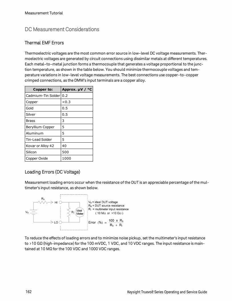
DCMeasurement Considerations
Thermal EMF Errors
Thermoelectric voltages are the most common error source in low–level DC voltage measurements. Ther-moelectric voltages are generated by circuit connections using dissimilar metals at different temperatures.Each metal–to–metal junction forms a thermocouple that generates a voltage proportional to the junc-tion temperature, as shown in the table below. You should minimize thermocouple voltages and tem-perature variations in low–level voltage measurements. The best connections use copper–to–coppercrimped connections, as the DMM’s input terminals are a copper alloy.
Copper to: Approx. µV / °C
Cadmium-Tin Solder 0.2
Copper <0.3
Gold 0.5
Silver 0.5
Brass 3
Beryllium Copper 5
Aluminum 5
Tin-Lead Solder 5
Kovar or Alloy 42 40
Silicon 500
Copper Oxide 1000
Loading Errors (DC Voltage)
Measurement loading errors occur when the resistance of the DUT is an appreciable percentage of the mul-timeter's input resistance, as shown below.
To reduce the effects of loading errors and to minimize noise pickup, set the multimeter's input resistanceto >10 GΩ (high-impedance) for the 100 mVDC, 1 VDC, and 10 VDC ranges. The input resistance is main-tained at 10 MΩ for the 100 VDC and 1000 VDC ranges.
Measurement Tutorial
162 Keysight Truevolt Series Operating and Service Guide
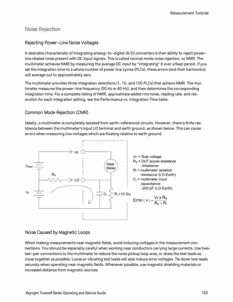
Noise Rejection
Rejecting Power–Line Noise Voltages
A desirable characteristic of integrating analog–to–digital (A/D) converters is their ability to reject power–line related noise present with DC input signals. This is called normal mode noise rejection, or NMR. Themultimeter achieves NMR by measuring the average DC input by "integrating" it over a fixed period. If youset the integration time to a whole number of power line cycles (PLCs), these errors (and their harmonics)will average out to approximately zero.
The multimeter provides three integration selections (1, 10, and 100 PLCs) that achieve NMR. The mul-timeter measures the power–line frequency (50 Hz or 60 Hz), and then determines the correspondingintegration time. For a complete listing of NMR, approximate added rms noise, reading rate, and res-olution for each integration setting, see the Performance vs. Integration Time table.
Common Mode Rejection (CMR)
Ideally, a multimeter is completely isolated from earth–referenced circuits. However, there is finite res-istance between the multimeter's input LO terminal and earth ground, as shown below. This can causeerrors when measuring low voltages which are floating relative to earth ground.
Noise Caused by Magnetic Loops
When making measurements near magnetic fields, avoid inducing voltages in the measurement con-nections. You should be especially careful when working near conductors carrying large currents. Use twis-ted–pair connections to the multimeter to reduce the noise pickup loop area, or dress the test leads asclose together as possible. Loose or vibrating test leads will also induce error voltages. Tie down test leadssecurely when operating near magnetic fields. Whenever possible, use magnetic shielding materials orincreased distance from magnetic sources.
Keysight Truevolt Series Operating and Service Guide 163
Measurement Tutorial
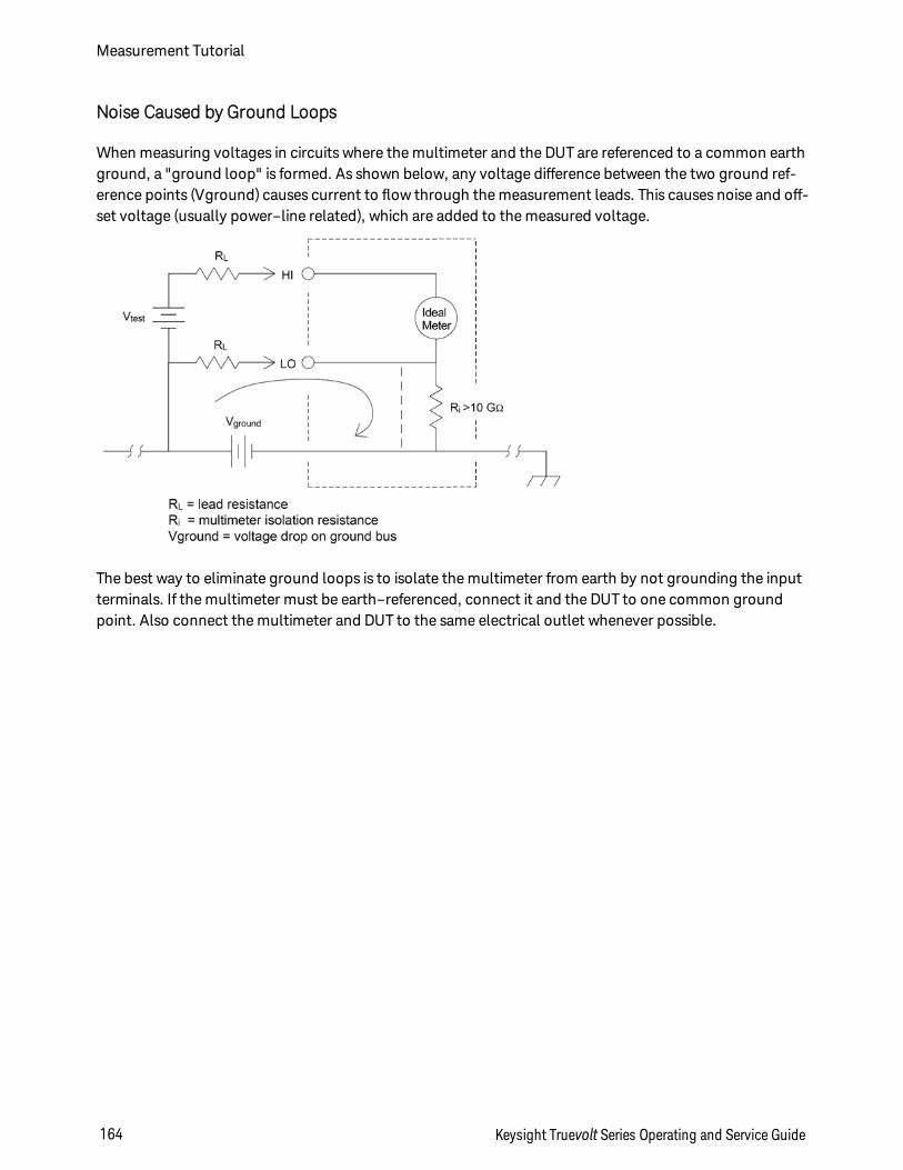
Noise Caused by Ground Loops
When measuring voltages in circuits where the multimeter and the DUT are referenced to a common earthground, a "ground loop" is formed. As shown below, any voltage difference between the two ground ref-erence points (Vground) causes current to flow through the measurement leads. This causes noise and off-set voltage (usually power–line related), which are added to the measured voltage.
The best way to eliminate ground loops is to isolate the multimeter from earth by not grounding the inputterminals. If the multimeter must be earth–referenced, connect it and the DUT to one common groundpoint. Also connect the multimeter and DUT to the same electrical outlet whenever possible.
Measurement Tutorial
164 Keysight Truevolt Series Operating and Service Guide
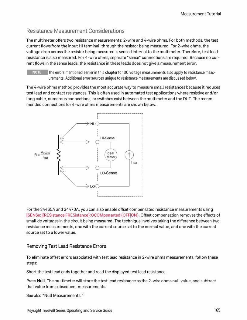
Resistance Measurement Considerations
The multimeter offers two resistance measurements: 2-wire and 4-wire ohms. For both methods, the testcurrent flows from the input HI terminal, through the resistor being measured. For 2-wire ohms, thevoltage drop across the resistor being measured is sensed internal to the multimeter. Therefore, test leadresistance is also measured. For 4-wire ohms, separate "sense" connections are required. Because no cur-rent flows in the sense leads, the resistance in these leads does not give a measurement error.
The errors mentioned earlier in this chapter for DC voltage measurements also apply to resistance meas-urements. Additional error sources unique to resistance measurements are discussed below.
The 4-wire ohms method provides the most accurate way to measure small resistances because it reducestest lead and contact resistances. This is often used in automated test applications where resistive and/orlong cable, numerous connections, or switches exist between the multimeter and the DUT. The recom-mended connections for 4-wire ohms measurements are shown below.
For the 34465A and 34470A, you can also enable offset compensated resistance measurements using[SENSe:]RESistance|FRESistance:OCOMpensated OFF|ON. Offset compensation removes the effects ofsmall dc voltages in the circuit being measured. The technique involves taking the difference between tworesistance measurements, one with the current source set to the normal value, and one with the currentsource set to a lower value.
Removing Test Lead Resistance Errors
To eliminate offset errors associated with test lead resistance in 2-wire ohms measurements, follow thesesteps:
Short the test lead ends together and read the displayed test lead resistance.
Press Null. The multimeter will store the test lead resistance as the 2-wire ohms null value, and subtractthat value from subsequent measurements.
See also "Null Measurements."
Keysight Truevolt Series Operating and Service Guide 165
Measurement Tutorial
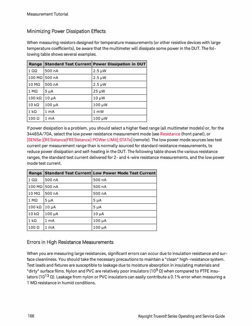
Minimizing Power Dissipation Effects
When measuring resistors designed for temperature measurements (or other resistive devices with largetemperature coefficients), be aware that the multimeter will dissipate some power in the DUT. The fol-lowing table shows several examples.
Range Standard Test Current Power Dissipation in DUT
1 GΩ 500 nA 2.5 µW
100 MΩ 500 nA 2.5 µW
10 MΩ 500 nA 2.5 µW
1 MΩ 5 µA 25 µW
100 kΩ 10 µA 10 µW
10 kΩ 100 µA 100 µW
1 kΩ 1 mA 1 mW
100 Ω 1 mA 100 µW
If power dissipation is a problem, you should select a higher fixed range (all multimeter models) or, for the34465A/70A, select the low power resistance measurement mode (see Resistance (front panel), or[SENSe:]RESistance|FRESistance:POWer:LIMit[:STATe] (remote). The low power mode sources less testcurrent per measurement range than is normally sourced for standard resistance measurements, toreduce power dissipation and self-heating in the DUT. The following table shows the various resistanceranges, the standard test current delivered for 2- and 4-wire resistance measurements, and the low powermode test current.
Range Standard Test Current Low Power Mode Test Current
1 GΩ 500 nA 500 nA
100 MΩ 500 nA 500 nA
10 MΩ 500 nA 500 nA
1 MΩ 5 µA 5 µA
100 kΩ 10 µA 5 µA
10 kΩ 100 µA 10 µA
1 kΩ 1 mA 100 µA
100 Ω 1 mA 100 µA
Errors in High Resistance Measurements
When you are measuring large resistances, significant errors can occur due to insulation resistance and sur-face cleanliness. You should take the necessary precautions to maintain a "clean" high–resistance system.Test leads and fixtures are susceptible to leakage due to moisture absorption in insulating materials and"dirty" surface films. Nylon and PVC are relatively poor insulators (109 Ω) when compared to PTFE insu-lators (1013 Ω). Leakage from nylon or PVC insulators can easily contribute a 0.1% error when measuring a1 MΩ resistance in humid conditions.
Measurement Tutorial
166 Keysight Truevolt Series Operating and Service Guide
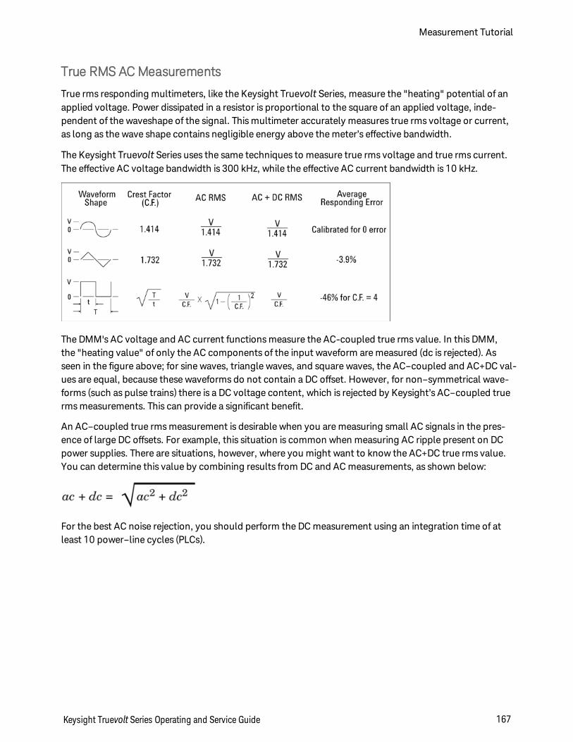
True RMS ACMeasurements
True rms responding multimeters, like the Keysight Truevolt Series, measure the "heating" potential of anapplied voltage. Power dissipated in a resistor is proportional to the square of an applied voltage, inde-pendent of the waveshape of the signal. This multimeter accurately measures true rms voltage or current,as long as the wave shape contains negligible energy above the meter’s effective bandwidth.
The Keysight Truevolt Series uses the same techniques to measure true rms voltage and true rms current.The effective AC voltage bandwidth is 300 kHz, while the effective AC current bandwidth is 10 kHz.
The DMM's AC voltage and AC current functions measure the AC-coupled true rms value. In this DMM,the "heating value" of only the AC components of the input waveform are measured (dc is rejected). Asseen in the figure above; for sine waves, triangle waves, and square waves, the AC–coupled and AC+DC val-ues are equal, because these waveforms do not contain a DC offset. However, for non–symmetrical wave-forms (such as pulse trains) there is a DC voltage content, which is rejected by Keysight’s AC–coupled truerms measurements. This can provide a significant benefit.
An AC–coupled true rms measurement is desirable when you are measuring small AC signals in the pres-ence of large DC offsets. For example, this situation is common when measuring AC ripple present on DCpower supplies. There are situations, however, where you might want to know the AC+DC true rms value.You can determine this value by combining results from DC and AC measurements, as shown below:
For the best AC noise rejection, you should perform the DC measurement using an integration time of atleast 10 power–line cycles (PLCs).
Keysight Truevolt Series Operating and Service Guide 167
Measurement Tutorial
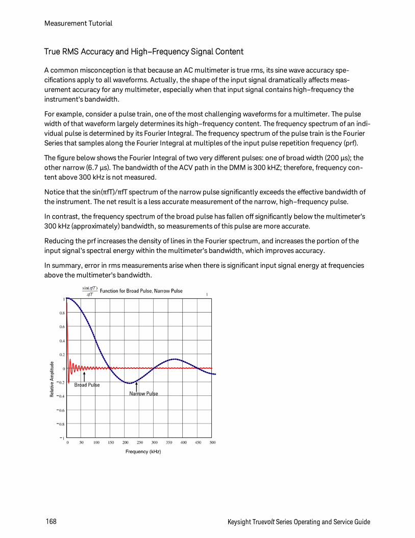
True RMS Accuracy and High–Frequency Signal Content
A common misconception is that because an AC multimeter is true rms, its sine wave accuracy spe-cifications apply to all waveforms. Actually, the shape of the input signal dramatically affects meas-urement accuracy for any multimeter, especially when that input signal contains high–frequency theinstrument’s bandwidth.
For example, consider a pulse train, one of the most challenging waveforms for a multimeter. The pulsewidth of that waveform largely determines its high–frequency content. The frequency spectrum of an indi-vidual pulse is determined by its Fourier Integral. The frequency spectrum of the pulse train is the FourierSeries that samples along the Fourier Integral at multiples of the input pulse repetition frequency (prf).
The figure below shows the Fourier Integral of two very different pulses: one of broad width (200 µs); theother narrow (6.7 µs). The bandwidth of the ACV path in the DMM is 300 kHZ; therefore, frequency con-tent above 300 kHz is not measured.
Notice that the sin(πfT)/πfT spectrum of the narrow pulse significantly exceeds the effective bandwidth ofthe instrument. The net result is a less accurate measurement of the narrow, high–frequency pulse.
In contrast, the frequency spectrum of the broad pulse has fallen off significantly below the multimeter’s300 kHz (approximately) bandwidth, so measurements of this pulse are more accurate.
Reducing the prf increases the density of lines in the Fourier spectrum, and increases the portion of theinput signal’s spectral energy within the multimeter’s bandwidth, which improves accuracy.
In summary, error in rms measurements arise when there is significant input signal energy at frequenciesabove the multimeter’s bandwidth.
Measurement Tutorial
168 Keysight Truevolt Series Operating and Service Guide
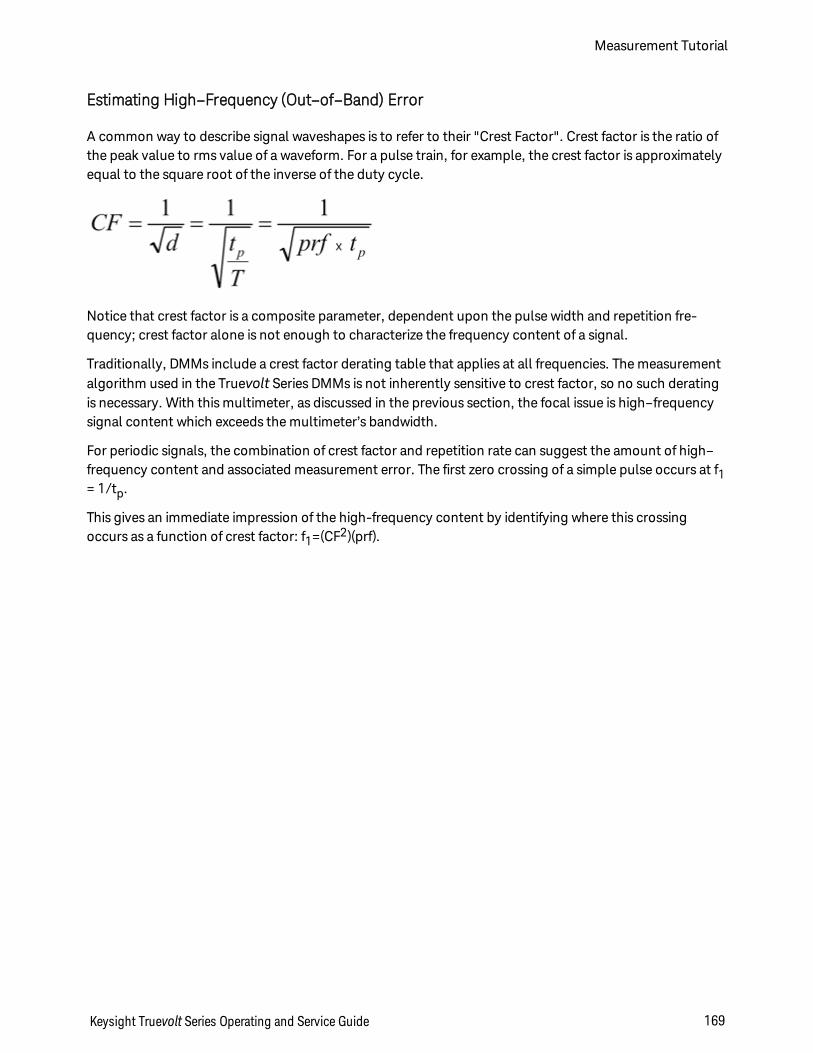
Estimating High–Frequency (Out–of–Band) Error
A common way to describe signal waveshapes is to refer to their "Crest Factor". Crest factor is the ratio ofthe peak value to rms value of a waveform. For a pulse train, for example, the crest factor is approximatelyequal to the square root of the inverse of the duty cycle.
Notice that crest factor is a composite parameter, dependent upon the pulse width and repetition fre-quency; crest factor alone is not enough to characterize the frequency content of a signal.
Traditionally, DMMs include a crest factor derating table that applies at all frequencies. The measurementalgorithm used in the Truevolt Series DMMs is not inherently sensitive to crest factor, so no such deratingis necessary. With this multimeter, as discussed in the previous section, the focal issue is high–frequencysignal content which exceeds the multimeter’s bandwidth.
For periodic signals, the combination of crest factor and repetition rate can suggest the amount of high–frequency content and associated measurement error. The first zero crossing of a simple pulse occurs at f1= 1/tp.
This gives an immediate impression of the high-frequency content by identifying where this crossingoccurs as a function of crest factor: f1=(CF2)(prf).
Keysight Truevolt Series Operating and Service Guide 169
Measurement Tutorial
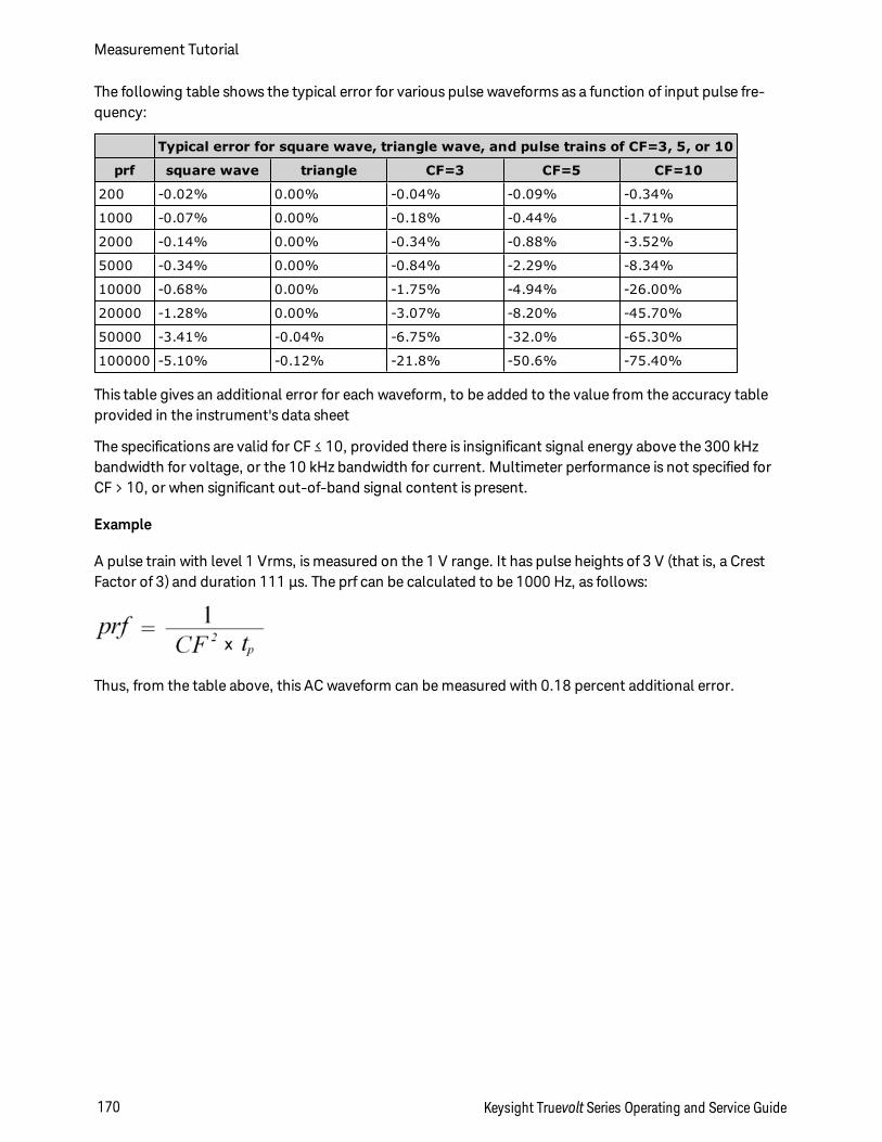
The following table shows the typical error for various pulse waveforms as a function of input pulse fre-quency:
Typical error for square wave, triangle wave, and pulse trains of CF=3, 5, or 10
prf square wave triangle CF=3 CF=5 CF=10
200 -0.02% 0.00% -0.04% -0.09% -0.34%
1000 -0.07% 0.00% -0.18% -0.44% -1.71%
2000 -0.14% 0.00% -0.34% -0.88% -3.52%
5000 -0.34% 0.00% -0.84% -2.29% -8.34%
10000 -0.68% 0.00% -1.75% -4.94% -26.00%
20000 -1.28% 0.00% -3.07% -8.20% -45.70%
50000 -3.41% -0.04% -6.75% -32.0% -65.30%
100000 -5.10% -0.12% -21.8% -50.6% -75.40%
This table gives an additional error for each waveform, to be added to the value from the accuracy tableprovided in the instrument's data sheet
The specifications are valid for CF ≤ 10, provided there is insignificant signal energy above the 300 kHzbandwidth for voltage, or the 10 kHz bandwidth for current. Multimeter performance is not specified forCF > 10, or when significant out-of-band signal content is present.
Example
A pulse train with level 1 Vrms, is measured on the 1 V range. It has pulse heights of 3 V (that is, a CrestFactor of 3) and duration 111 µs. The prf can be calculated to be 1000 Hz, as follows:
Thus, from the table above, this AC waveform can be measured with 0.18 percent additional error.
Measurement Tutorial
170 Keysight Truevolt Series Operating and Service Guide
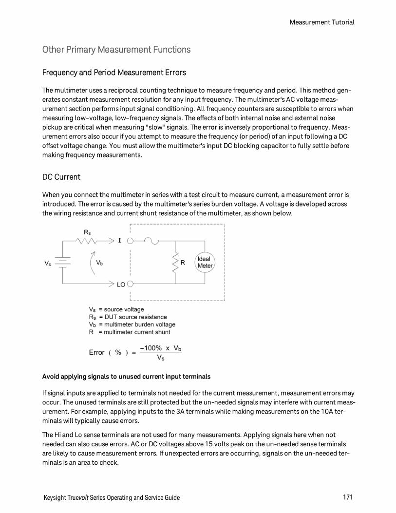
Other Primary Measurement Functions
Frequency and Period Measurement Errors
The multimeter uses a reciprocal counting technique to measure frequency and period. This method gen-erates constant measurement resolution for any input frequency. The multimeter's AC voltage meas-urement section performs input signal conditioning. All frequency counters are susceptible to errors whenmeasuring low–voltage, low–frequency signals. The effects of both internal noise and external noisepickup are critical when measuring "slow" signals. The error is inversely proportional to frequency. Meas-urement errors also occur if you attempt to measure the frequency (or period) of an input following a DCoffset voltage change. You must allow the multimeter's input DC blocking capacitor to fully settle beforemaking frequency measurements.
DC Current
When you connect the multimeter in series with a test circuit to measure current, a measurement error isintroduced. The error is caused by the multimeter's series burden voltage. A voltage is developed acrossthe wiring resistance and current shunt resistance of the multimeter, as shown below.
Avoid applying signals to unused current input terminals
If signal inputs are applied to terminals not needed for the current measurement, measurement errors mayoccur. The unused terminals are still protected but the un-needed signals may interfere with current meas-urement. For example, applying inputs to the 3A terminals while making measurements on the 10A ter-minals will typically cause errors.
The Hi and Lo sense terminals are not used for many measurements. Applying signals here when notneeded can also cause errors. AC or DC voltages above 15 volts peak on the un-needed sense terminalsare likely to cause measurement errors. If unexpected errors are occurring, signals on the un-needed ter-minals is an area to check.
Keysight Truevolt Series Operating and Service Guide 171
Measurement Tutorial
Temperature Measurements
Temperature measurements require a temperature transducer probe. The supported probes are 2-wireand 4-wire RTDs, 2-wire and 4-wire thermistors (5 k 44007 type, see Thermistor Requirements below),and, for the 34465A/70A only, type E, J, K, N, R, or T thermocouples.
Probe Type Choice
RTD's provide very accurate, highly linear relationships between resistance and temperature, over a rangeof roughly –200 to 500 °C. There is very little conversion complexity for an RTD because it is so intrinsicallylinear. The multimeter provides measurement for the IEC751 standard RTD, which has a sensitivity of0.385%/°C.
Thermistors consist of semiconductor materials, and provide roughly ten times the sensitivity of the RTD.Because they are semiconductors, their temperature range is more limited, commonly to –80 to 150 °C.Thermistors have highly non–linear temperature–resistance relationships; therefore their conversionalgorithms are more complex. The Truevolt Series multimeters use the standard Hart–Steinhart Approx-imation to provide accurate conversions, with a typical resolution of .08 °C.
Thermistor Requirements
The DMM converts the measured thermistor resistance to temperature using the Steinhart-Hart ther-mistor equation:
1⁄T = A + B (Ln(R)) + C (Ln(R))3
Where:
A, B, and C are constants provided by the thermistor manufacturer and derived from threetemperature test points.
R = Thermistor resistance in Ω.
T = Temperature in degrees K.
Important: Use only a 5 kΩ 44007-type thermistor. This type thermistor has constants of A = 1.285e-3, B= 2.362e-4, C = 9.285e-8. Using an incorrect type of thermistor can result in errors greater than 20 °C fora temperature being measured of 100 °C.
2-Wire vs. 4-Wire Measurements
As with resistance measurements, four-wire temperature measurements are more accurate, becauseerrors due to lead wire resistance are completely eliminated. Alternately, you can use the multimeter’sNull function to remove the test lead resistance from the measurement (see NULL Reading below).
Measurement Tutorial
172 Keysight Truevolt Series Operating and Service Guide
NULL Reading
The DMM allows a separate null setting to be saved for the temperature function. When making null meas-urements, each reading is the difference between a stored null value and the input signal. One applicationof NULL is to increase accuracy of two-wire resistance measurements by first nulling the closed–circuittest lead resistance.
Autozero On/Off
Enabling the autozero feature (ON) provides greater accuracy; however, the additional measurement (ofzero) reduces the reading speed.
Making High–Speed ACMeasurements
The multimeter's AC voltage and AC current functions implement three low–frequency filters. These filtersallow you to trade–off minimum measured frequency for faster reading speed. The FAST filter settles in0.025 seconds, and is useful for frequencies above 200 Hz. The MEDIUM filter settles in 0.625 seconds forvoltage and 0.25 seconds for current, and is useful for measurements above 20 Hz. The SLOW filter settlesin 2.5 seconds for voltage and 1.66 seconds for current, and is useful for frequencies above 3 Hz.
With a few precautions, you can perform AC measurements at speeds up to 500 readings per second. Usemanual ranging to eliminate autoranging delays. By setting the trigger delay to 0, the FAST, MEDIUM, andSLOW filters allow up to 500, 150, and 50 readings per second, but with reduced accuracy because the fil-ter may not fully settle. If the sample–to–sample levels are similar, little settling time is required for eachnew reading. Under this specialized condition, the MEDIUM filter provides reduced accuracy results at 20readings per second, and the FAST filter provides reduced accuracy results at 200 readings per second.
AC Fil-ter
Filter Band-width
Settling Time(s)
Full Settling (rdg-s/s)
Partial Set-tling
Maximum rdg-s/s
ACV ACI ACV ACI ACV/ACI ACV/ACI
Slow 3 Hz 2.5 1.67 0.4 0.6 2 50
Medium 20 Hz 0.63 0.25 1.6 4 20 150
Fast 200 Hz 0.025 0.025 40 40 200 500
In applications where sample–to–sample levels vary widely, but the DC offset level does not change, theMEDIUM filter settles at 2 to 4 readings per second (depending upon the lowest frequency component inthe waveform) as shown in the following table:
Lowest Frequency Component 20 Hz 50 Hz 100 Hz 200 Hz
AC Current (allowable rate in rdgs/s) 4 4 4 4
AC Voltage (allowable rate in rdgs/s) 2 3 4 4
For AC voltage, additional settling time may be required when the DC level varies from sample to sample.The default sample delays allow for a DC level change of 3% of range for all filters. If the DC level changeexceeds these levels, additional settling time is required. The multimeter's DC blocking circuitry has a set-tling time constant of 0.2 seconds. This settling time only affects measurement accuracy when DC offsetlevels vary from sample to sample. If maximum measurement speed is desired, you may want to add an
Keysight Truevolt Series Operating and Service Guide 173
Measurement Tutorial
external DC blocking circuit for circuitry with significant DC voltages present. This circuit can be as simpleas a resistor and a capacitor.
For AC current, additional settling time is not required when the DC level varies sample to sample.
Making High–Speed DC and Resistance Measurements
If you have the DIG (digitizing) option, simply select [Acquire] > Digitize to select the fastest DCV orDCI measurements. If you do not have the DIG option, or for resistance measurements, to make the fastest(but least accurate) DC or resistance measurements:
l Set the integration time (NPLC or aperture) to minimum
l Select a fixed range (autorange off)
l Disable autozero
l Disable offset compensation (resistance measurements)
Refer to the particular measurement type in Measurements for more information on the above functions.
Measurement Tutorial
174 Keysight Truevolt Series Operating and Service Guide
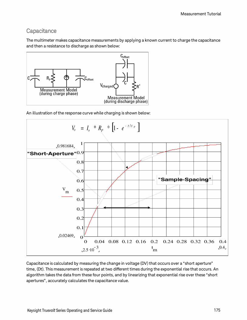
Capacitance
The multimeter makes capacitance measurements by applying a known current to charge the capacitanceand then a resistance to discharge as shown below:
An illustration of the response curve while charging is shown below:
Capacitance is calculated by measuring the change in voltage (DV) that occurs over a “short aperture”time, (Dt). This measurement is repeated at two different times during the exponential rise that occurs. Analgorithm takes the data from these four points, and by linearizing that exponential rise over these “shortapertures”, accurately calculates the capacitance value.
Keysight Truevolt Series Operating and Service Guide 175
Measurement Tutorial
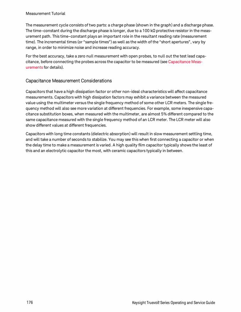
The measurement cycle consists of two parts: a charge phase (shown in the graph) and a discharge phase.The time–constant during the discharge phase is longer, due to a 100 kΩ protective resistor in the meas-urement path. This time–constant plays an important role in the resultant reading rate (measurementtime). The incremental times (or “sample times”) as well as the width of the “short apertures”, vary byrange, in order to minimize noise and increase reading accuracy.
For the best accuracy, take a zero null measurement with open probes, to null out the test lead capa-citance, before connecting the probes across the capacitor to be measured (see Capacitance Meas-urements for details).
Capacitance Measurement Considerations
Capacitors that have a high dissipation factor or other non-ideal characteristics will affect capacitancemeasurements. Capacitors with high dissipation factors may exhibit a variance between the measuredvalue using the multimeter versus the single frequency method of some other LCR meters. The single fre-quency method will also see more variation at different frequencies. For example, some inexpensive capa-citance substitution boxes, when measured with the multimeter, are almost 5% different compared to thesame capacitance measured with the single frequency method of an LCR meter. The LCR meter will alsoshow different values at different frequencies.
Capacitors with long time constants (dielectric absorption) will result in slow measurement settling time,and will take a number of seconds to stabilize. You may see this when first connecting a capacitor or whenthe delay time to make a measurement is varied. A high quality film capacitor typically shows the least ofthis and an electrolytic capacitor the most, with ceramic capacitors typically in between.
Measurement Tutorial
176 Keysight Truevolt Series Operating and Service Guide
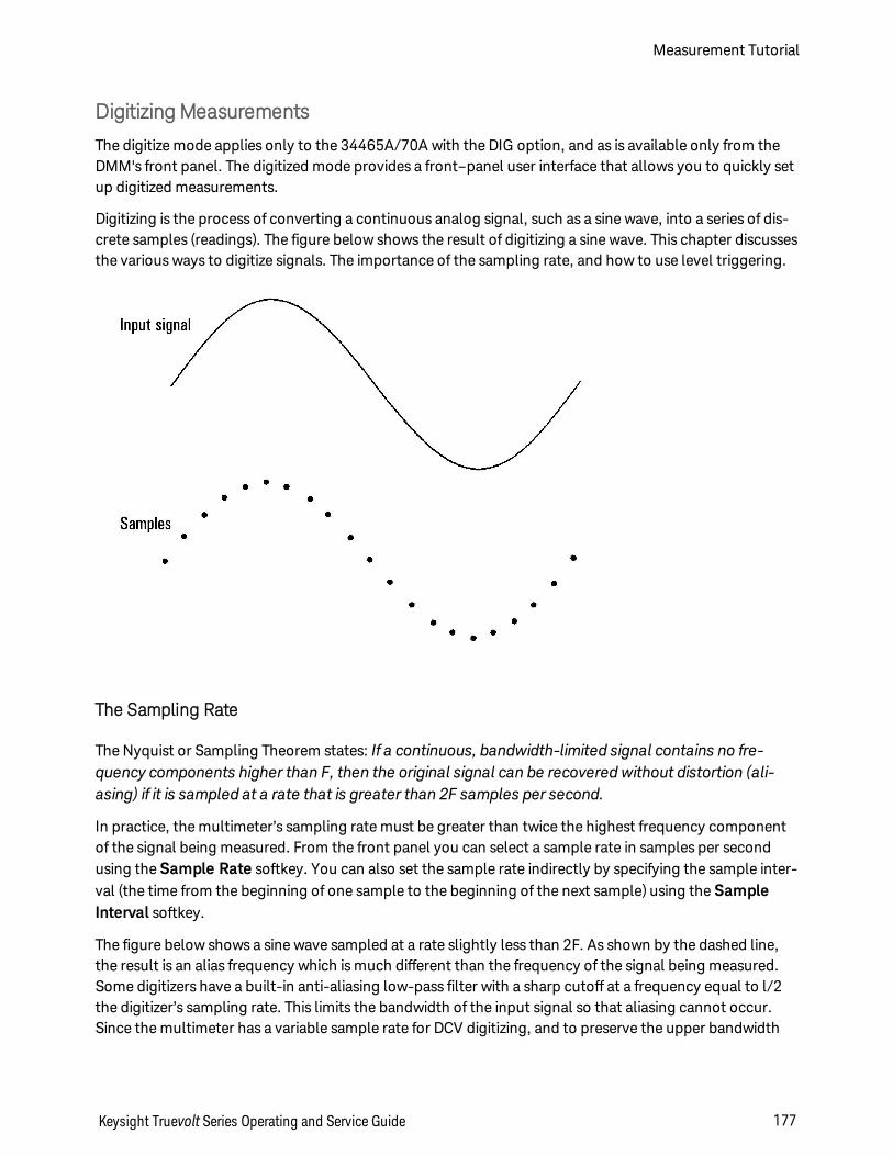
DigitizingMeasurements
The digitize mode applies only to the 34465A/70A with the DIG option, and as is available only from theDMM's front panel. The digitized mode provides a front–panel user interface that allows you to quickly setup digitized measurements.
Digitizing is the process of converting a continuous analog signal, such as a sine wave, into a series of dis-crete samples (readings). The figure below shows the result of digitizing a sine wave. This chapter discussesthe various ways to digitize signals. The importance of the sampling rate, and how to use level triggering.
The Sampling Rate
The Nyquist or Sampling Theorem states: If a continuous, bandwidth-limited signal contains no fre-quency components higher than F, then the original signal can be recoveredwithout distortion (ali-asing) if it is sampled at a rate that is greater than 2F samples per second.
In practice, the multimeter’s sampling rate must be greater than twice the highest frequency componentof the signal being measured. From the front panel you can select a sample rate in samples per secondusing the Sample Rate softkey. You can also set the sample rate indirectly by specifying the sample inter-val (the time from the beginning of one sample to the beginning of the next sample) using the SampleInterval softkey.
The figure below shows a sine wave sampled at a rate slightly less than 2F. As shown by the dashed line,the result is an alias frequency which is much different than the frequency of the signal being measured.Some digitizers have a built-in anti-aliasing low-pass filter with a sharp cutoff at a frequency equal to l/2the digitizer’s sampling rate. This limits the bandwidth of the input signal so that aliasing cannot occur.Since the multimeter has a variable sample rate for DCV digitizing, and to preserve the upper bandwidth
Keysight Truevolt Series Operating and Service Guide 177
Measurement Tutorial
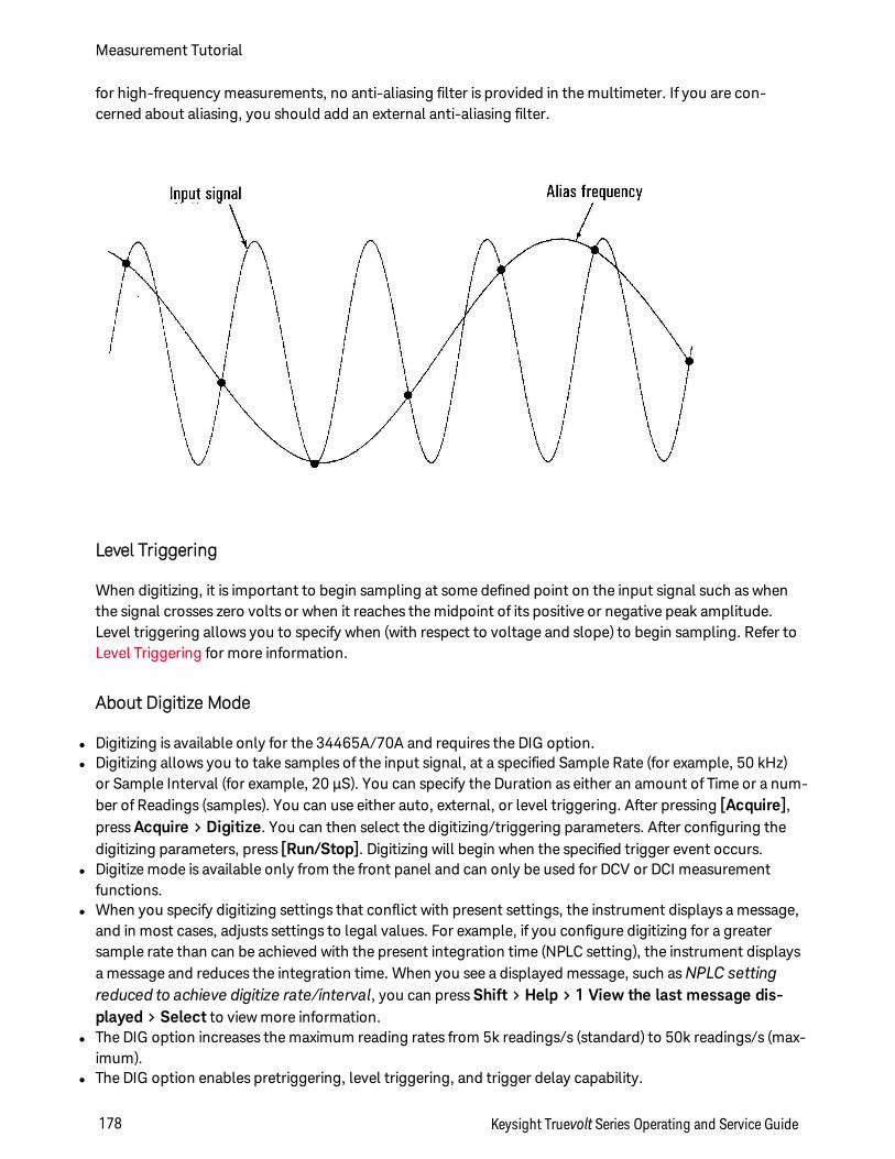
for high-frequency measurements, no anti-aliasing filter is provided in the multimeter. If you are con-cerned about aliasing, you should add an external anti-aliasing filter.
Level Triggering
When digitizing, it is important to begin sampling at some defined point on the input signal such as whenthe signal crosses zero volts or when it reaches the midpoint of its positive or negative peak amplitude.Level triggering allows you to specify when (with respect to voltage and slope) to begin sampling. Refer toLevel Triggering for more information.
About Digitize Mode
l Digitizing is available only for the 34465A/70A and requires the DIG option.l Digitizing allows you to take samples of the input signal, at a specified Sample Rate (for example, 50 kHz)
or Sample Interval (for example, 20 µS). You can specify the Duration as either an amount of Time or a num-ber of Readings (samples). You can use either auto, external, or level triggering. After pressing [Acquire],press Acquire > Digitize. You can then select the digitizing/triggering parameters. After configuring thedigitizing parameters, press [Run/Stop]. Digitizing will begin when the specified trigger event occurs.
l Digitize mode is available only from the front panel and can only be used for DCV or DCI measurementfunctions.
l When you specify digitizing settings that conflict with present settings, the instrument displays a message,and in most cases, adjusts settings to legal values. For example, if you configure digitizing for a greatersample rate than can be achieved with the present integration time (NPLC setting), the instrument displaysa message and reduces the integration time. When you see a displayed message, such asNPLC settingreduced to achieve digitize rate/interval, you can press Shift > Help > 1 View the last message dis-played > Select to view more information.
l The DIG option increases the maximum reading rates from 5k readings/s (standard) to 50k readings/s (max-imum).
l The DIG option enables pretriggering, level triggering, and trigger delay capability.
Measurement Tutorial
178 Keysight Truevolt Series Operating and Service Guide
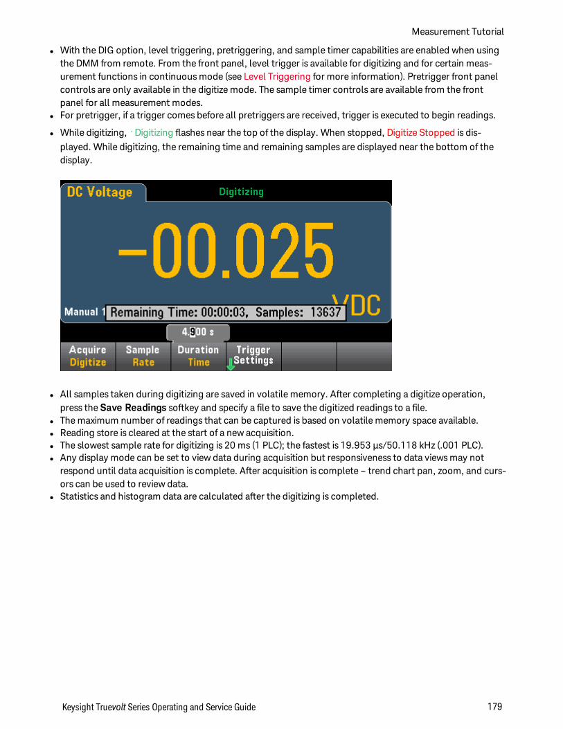
l With the DIG option, level triggering, pretriggering, and sample timer capabilities are enabled when usingthe DMM from remote. From the front panel, level trigger is available for digitizing and for certain meas-urement functions in continuous mode (see Level Triggering for more information). Pretrigger front panelcontrols are only available in the digitize mode. The sample timer controls are available from the frontpanel for all measurement modes.
l For pretrigger, if a trigger comes before all pretriggers are received, trigger is executed to begin readings.
l While digitizing, •Digitizing flashes near the top of the display. When stopped, Digitize Stopped is dis-played. While digitizing, the remaining time and remaining samples are displayed near the bottom of thedisplay.
l All samples taken during digitizing are saved in volatile memory. After completing a digitize operation,press the Save Readings softkey and specify a file to save the digitized readings to a file.
l The maximum number of readings that can be captured is based on volatile memory space available.l Reading store is cleared at the start of a new acquisition.l The slowest sample rate for digitizing is 20 ms (1 PLC); the fastest is 19.953 µs/50.118 kHz (.001 PLC).l Any display mode can be set to view data during acquisition but responsiveness to data views may not
respond until data acquisition is complete. After acquisition is complete – trend chart pan, zoom, and curs-ors can be used to review data.
l Statistics and histogram data are calculated after the digitizing is completed.
Keysight Truevolt Series Operating and Service Guide 179
Measurement Tutorial

Data Log and Digitizing Local Remote Interaction
Loss of data possible - local to remote transition clears instrument memory: When data logging ordigitizing to memory, if you access the instrument from remote (send a SCPI or common command)* andthen return to local (by pressing [Local]), the readings in memory are cleared and the instrument returnsto Continuous mode.
For data logging only, you can prevent this situation by data logging to a file instead of to memory (seeData Log Mode for details). You can also prevent this from happening for data logging or digitizing by tak-ing steps to keep the instrument from being accessed from remote. To prevent remote access, you maywant to disconnect the LAN, GPIB, and USB interface cables from the instrument before starting the meas-urements. To prevent remote access via LAN, you can connect the instrument behind a router to minimizethe possibility of remote access. You can also disable the various I/O interfaces from the front panel menusunder [Utility] > I/O Config.
To view the status of a data logging or digitizing operation remotely, use the instrument’s Web User Inter-face. The Web User Interface monitor does not set the instrument to remote.
*When accessed from remote, the instrument will continue data logging or digitizing to completion, and you can retrieve the read-ings from remote.
Measurement Tutorial
180 Keysight Truevolt Series Operating and Service Guide
Data LogMode
The Data Log mode is standard on the 34465A and 34470A only, as is available only from the DMM's frontpanel. Data Log mode provides a front–panel user interface that allows you to set up data logging into theinstrument’s non–volatile memory, or to internal/external file(s), without programming, and without a con-nection to a computer. Once you have finished collecting data, you can view it from the front panel, or youcan transfer the data to your computer. Data Log mode allows you to log a specified number of readings,or readings acquired for a specified period of time, to instrument memory or to internal or external datafiles.
To select Data Log mode, press [Acquire] Acquire > Data Log. You can then select the Sample Interval(time between measurements - for example, 500 ms), Duration as either an amount of Time or a number ofReadings, whether to Start after a Delay or at a specific Time of Day, and whether to Log to Memory or Logto File(s). After configuring the data logging parameters, press [Run/Stop]. Data logging will begin fol-lowing the specified Delay or at the specified Time of Day.
Loss of data possible - local to remote transition clears instrument memory: Whendata logging or digitizing to memory, if you access the instrument from remote (send a SCPIor common command)* and then return to local (by pressing [Local]), the readings inmemory are cleared and the instrument returns to Continuous mode.
For data logging only, you can prevent this situation by data logging to a file instead of tomemory (see Data Log Mode for details). You can also prevent this from happening for datalogging or digitizing by taking steps to keep the instrument from being accessed fromremote. To prevent remote access, you may want to disconnect the LAN, GPIB, and USBinterface cables from the instrument before starting the measurements. To prevent remoteaccess via LAN, you can connect the instrument behind a router to minimize the possibility ofremote access. You can also disable the various I/O interfaces from the front panel menusunder [Utility] > I/O Config.
To view the status of a data logging or digitizing operation remotely, use the instrument’sWeb User Interface. The Web User Interface monitor does not set the instrument to remote.
*When accessed from remote, the instrument will continue data logging or digitizing to completion, and you canretrieve the readings from remote.
Data Log Mode Features
l The Data Log mode is available for DC voltage, DC current, AC voltage, AC current, 2-wire and 4-wireresistance, frequency, period, temperature, capacitance, and ratio measurements. The Data Log modeis not available for the continuity or diode functions.
l The maximum data log rate is 1000 readings/sec. Note: The maximum reading rate may be limited bysettings already configured when entering data log mode (particularly NPLC settings for DC and res-istance measurements). In this situation, press the measurement function key (for example, DCV) anddecrease the aperture setting (either NPLC or Time).
Keysight Truevolt Series Operating and Service Guide 181
Measurement Tutorial
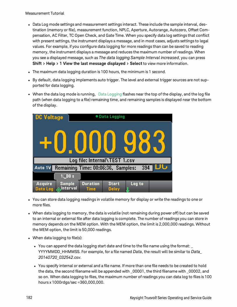
l Data Log mode settings and measurement settings interact. These include the sample interval, des-tination (memory or file), measurement function, NPLC, Aperture, Autorange, Autozero, Offset Com-pensation, AC Filter, TC Open Check, and Gate Time. When you specify data log settings that conflictwith present settings, the instrument displays a message, and in most cases, adjusts settings to legalvalues. For example, if you configure data logging for more readings than can be saved to readingmemory, the instrument displays a message and reduces the maximum number of readings. Whenyou see a displayed message, such as The data logging Sample Interval increased, you can pressShift > Help > 1 View the last message displayed > Select to view more information.
l The maximum data logging duration is 100 hours, the minimum is 1 second.
l By default, data logging implements auto trigger. The level and external trigger sources are not sup-ported for data logging.
l When the data log mode is running, •Data Logging flashes near the top of the display, and the log filepath (when data logging to a file) remaining time, and remaining samples is displayed near the bottomof the display.
l You can store data logging readings in volatile memory for display or write the readings to one ormore files.
l When data logging to memory, the data is volatile (not remaining during power off) but can be savedto an internal or external file after data logging is complete. The number of readings you can store inmemory depends on the MEM option. With the MEM option, the limit is 2,000,000 readings. Withoutthe MEM option, the limit is 50,000 readings.
l When data logging to file(s):
l You can append the data logging start date and time to the file name using the format: _YYYYMMDD_HHMMSS. For example, for a file named Data, the result will be similar to Data_20140720_032542.csv.
l You specify internal or external and a file name. If more than one file needs to be created to holdthe data, the second filename will be appended with _00001, the third filename with _00002, andso on. When data logging to files, the maximum number of readings you can data log to files is 100hours x 1000rdgs/sec =360,000,000.
Measurement Tutorial
182 Keysight Truevolt Series Operating and Service Guide
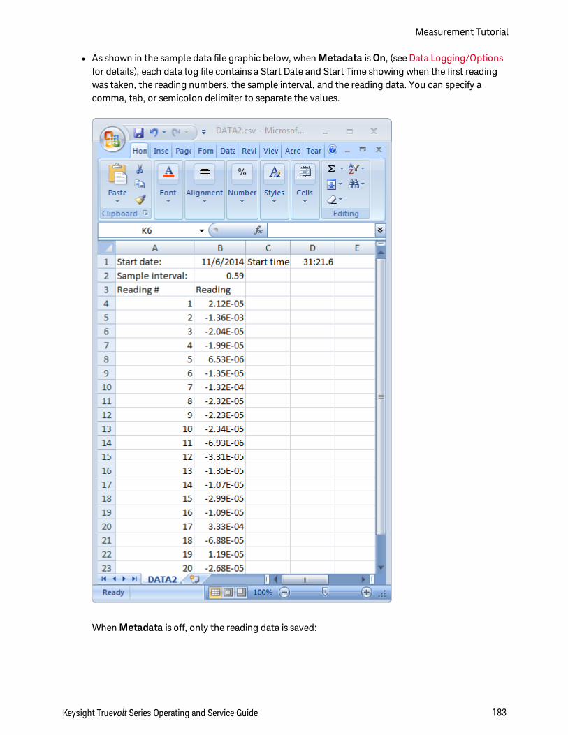
l As shown in the sample data file graphic below, when Metadata is On, (see Data Logging/Optionsfor details), each data log file contains a Start Date and Start Time showing when the first readingwas taken, the reading numbers, the sample interval, and the reading data. You can specify acomma, tab, or semicolon delimiter to separate the values.
When Metadata is off, only the reading data is saved:
Keysight Truevolt Series Operating and Service Guide 183
Measurement Tutorial
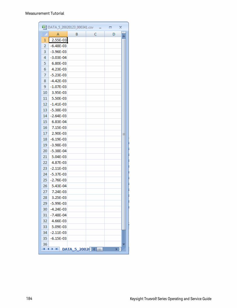
Measurement Tutorial
184 Keysight Truevolt Series Operating and Service Guide
Data Logging and the Trend Chart Display
l When data logging to memory, the trend chart maps each reading to a dot in a pixel column, draws aline between multiple dots in each column, and draws a line from the last reading in a column to thefirst reading in the next column.
l When data logging to a file, if the instrument determines the readings will fit in memory, the trendchart behaves as it does when data logging to memory. If there are too many readings to save inmemory, the trend chart behaves in a manner similar to that of the continuous measurement mode.That is, the number of readings shown per pixel column depends on the reading rate and the selectedTime Window.
Keysight Truevolt Series Operating and Service Guide 185
Measurement Tutorial
Data Log and Digitizing Local Remote Interaction
Loss of data possible - local to remote transition clears instrument memory: When data logging ordigitizing to memory, if you access the instrument from remote (send a SCPI or common command)* andthen return to local (by pressing [Local]), the readings in memory are cleared and the instrument returnsto Continuous mode.
For data logging only, you can prevent this situation by data logging to a file instead of to memory (seeData Log Mode for details). You can also prevent this from happening for data logging or digitizing by tak-ing steps to keep the instrument from being accessed from remote. To prevent remote access, you maywant to disconnect the LAN, GPIB, and USB interface cables from the instrument before starting the meas-urements. To prevent remote access via LAN, you can connect the instrument behind a router to minimizethe possibility of remote access. You can also disable the various I/O interfaces from the front panel menusunder [Utility] > I/O Config.
To view the status of a data logging or digitizing operation remotely, use the instrument’s Web User Inter-face. The Web User Interface monitor does not set the instrument to remote.
*When accessed from remote, the instrument will continue data logging or digitizing to completion, and you can retrieve the read-ings from remote.
Measurement Tutorial
186 Keysight Truevolt Series Operating and Service Guide
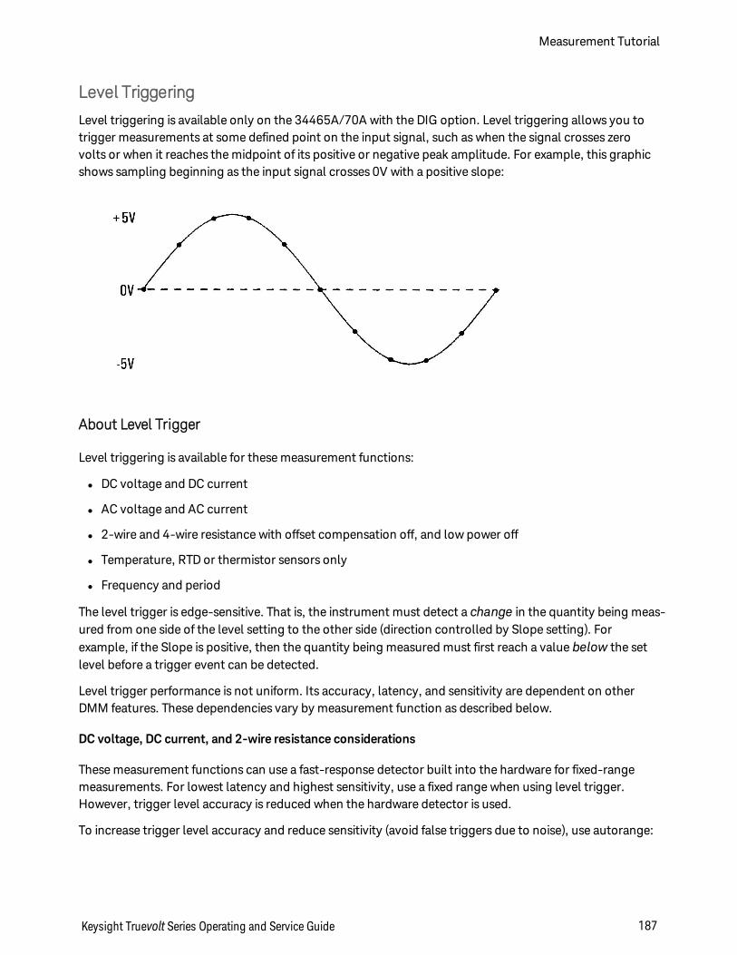
Level Triggering
Level triggering is available only on the 34465A/70A with the DIG option. Level triggering allows you totrigger measurements at some defined point on the input signal, such as when the signal crosses zerovolts or when it reaches the midpoint of its positive or negative peak amplitude. For example, this graphicshows sampling beginning as the input signal crosses 0V with a positive slope:
About Level Trigger
Level triggering is available for these measurement functions:
l DC voltage and DC current
l AC voltage and AC current
l 2-wire and 4-wire resistance with offset compensation off, and low power off
l Temperature, RTD or thermistor sensors only
l Frequency and period
The level trigger is edge-sensitive. That is, the instrument must detect a change in the quantity being meas-ured from one side of the level setting to the other side (direction controlled by Slope setting). Forexample, if the Slope is positive, then the quantity being measured must first reach a value below the setlevel before a trigger event can be detected.
Level trigger performance is not uniform. Its accuracy, latency, and sensitivity are dependent on otherDMM features. These dependencies vary by measurement function as described below.
DC voltage, DC current, and 2-wire resistance considerations
These measurement functions can use a fast-response detector built into the hardware for fixed-rangemeasurements. For lowest latency and highest sensitivity, use a fixed range when using level trigger.However, trigger level accuracy is reduced when the hardware detector is used.
To increase trigger level accuracy and reduce sensitivity (avoid false triggers due to noise), use autorange:
Keysight Truevolt Series Operating and Service Guide 187
Measurement Tutorial
l When auto-range is enabled, trigger level accuracy is increased, latency is increased, and sensitivity isdecreased as the aperture or NPLC setting is increased.
l When auto-range is enabled, trigger level accuracy is increased, latency is increased, and sensitivity isdecreased if autozero is enabled.
l When auto-range is enabled, range changes may be made while waiting for the trigger crossing whichcan cause additional latency/uncertainty.
4-wire resistance and temperature considerations
l Trigger level accuracy is increased, latency is increased, and sensitivity is decreased as aperture orNPLC is increased.
l Fixed range (only available for resistance) eliminates uncertainties (due to range change) in triggerlatency.
AC voltage and AC current considerations
l Trigger latency is increased, and sensitivity is decreased as filter bandwidth is increased.
l Trigger latency can be controlled by trigger delay setting.
l Fixed range eliminates uncertainties (due to range change) in trigger latency.
l Autorange uncertainties become worse as filter bandwidth is increased.
Frequency and period considerations
l Trigger level accuracy is increased, latency is increased, and sensitivity is decreased as gate time isincreased.
l Fixed voltage range eliminates uncertainties (due to range change) in trigger latency.
Measurement Tutorial
188 Keysight Truevolt Series Operating and Service Guide
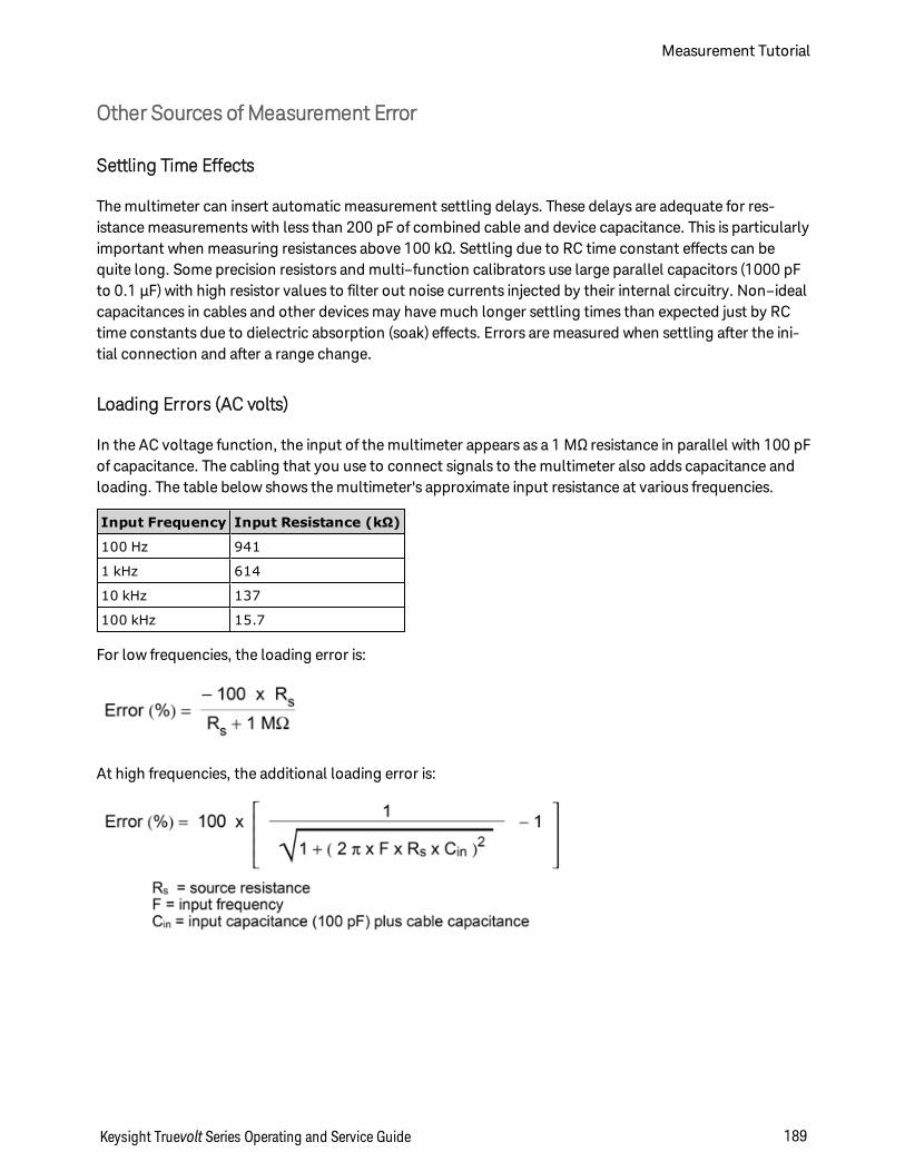
Other Sources of Measurement Error
Settling Time Effects
The multimeter can insert automatic measurement settling delays. These delays are adequate for res-istance measurements with less than 200 pF of combined cable and device capacitance. This is particularlyimportant when measuring resistances above 100 kΩ. Settling due to RC time constant effects can bequite long. Some precision resistors and multi–function calibrators use large parallel capacitors (1000 pFto 0.1 µF) with high resistor values to filter out noise currents injected by their internal circuitry. Non–idealcapacitances in cables and other devices may have much longer settling times than expected just by RCtime constants due to dielectric absorption (soak) effects. Errors are measured when settling after the ini-tial connection and after a range change.
Loading Errors (AC volts)
In the AC voltage function, the input of the multimeter appears as a 1 MΩ resistance in parallel with 100 pFof capacitance. The cabling that you use to connect signals to the multimeter also adds capacitance andloading. The table below shows the multimeter's approximate input resistance at various frequencies.
Input Frequency Input Resistance (kΩ)
100 Hz 941
1 kHz 614
10 kHz 137
100 kHz 15.7
For low frequencies, the loading error is:
At high frequencies, the additional loading error is:
Keysight Truevolt Series Operating and Service Guide 189
Measurement Tutorial
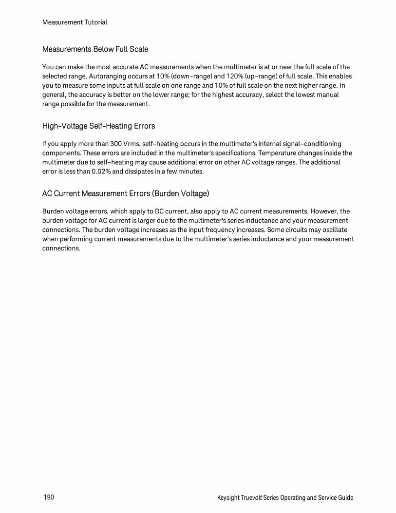
Measurements Below Full Scale
You can make the most accurate AC measurements when the multimeter is at or near the full scale of theselected range. Autoranging occurs at 10% (down–range) and 120% (up–range) of full scale. This enablesyou to measure some inputs at full scale on one range and 10% of full scale on the next higher range. Ingeneral, the accuracy is better on the lower range; for the highest accuracy, select the lowest manualrange possible for the measurement.
High-Voltage Self-Heating Errors
If you apply more than 300 Vrms, self–heating occurs in the multimeter's internal signal–conditioningcomponents. These errors are included in the multimeter's specifications. Temperature changes inside themultimeter due to self–heating may cause additional error on other AC voltage ranges. The additionalerror is less than 0.02% and dissipates in a few minutes.
AC Current Measurement Errors (Burden Voltage)
Burden voltage errors, which apply to DC current, also apply to AC current measurements. However, theburden voltage for AC current is larger due to the multimeter's series inductance and your measurementconnections. The burden voltage increases as the input frequency increases. Some circuits may oscillatewhen performing current measurements due to the multimeter's series inductance and your measurementconnections.
Measurement Tutorial
190 Keysight Truevolt Series Operating and Service Guide
Low–Level Measurement Errors
AC voltage measurements less than 100 mV are especially susceptible to errors introduced by extraneousnoise sources. An exposed test lead acts as an antenna and a properly functioning DMM will measure thesignals received. The entire measurement path, including the power line, act as a loop antenna. Cir-culating currents in the loop create error voltages across any impedances in series with the DMM's input.Therefore, you should apply low–level AC voltages to the DMM through shielded cables, with the shieldconnected to the input LO terminal.
Connect the DMM and the AC source to the same electrical outlet whenever possible. You should also min-imize the area of any ground loops that cannot be avoided. A high–impedance source is more susceptibleto noise pickup than a low–impedance source. You can reduce the high–frequency impedance of a sourceby placing a capacitor in parallel with the DMM's input terminals. You may have to experiment to determ-ine the correct capacitor for your application.
Most extraneous noise is not correlated with the input signal. You can determine the error as shownbelow.
Correlated noise, while rare, is especially detrimental because it always adds directly to the input signal.Measuring a low–level signal with the same frequency as the local power line is a common situation that isprone to this error.
Common Mode Errors
Errors are generated when the multimeter's input LO terminal is driven with an AC voltage relative toearth. The most common situation where unnecessary common mode voltages are created is when theoutput of an AC calibrator is connected to the multimeter "backwards." Ideally, a multimeter reads thesame regardless of how the source is connected. Both source and multimeter effects can degrade thisideal situation. Because of the capacitance between the input LO terminal and earth (approximately 200pF), the source will experience different loading depending on how the input is applied. The magnitude ofthe error is dependent upon the source's response to this loading.
The DMM's measurement circuitry, while extensively shielded, responds differently in the backward inputcase due to slight differences in stray capacitance to earth. The DMM's errors are greatest for high–voltage, high–frequency inputs. Typically, the DMM exhibits about 0.06% additional error for a 100 V, 100kHz reverse input. You can use the grounding techniques described for DC common mode problems tominimize AC common mode voltages.
Keysight Truevolt Series Operating and Service Guide 191
Measurement Tutorial
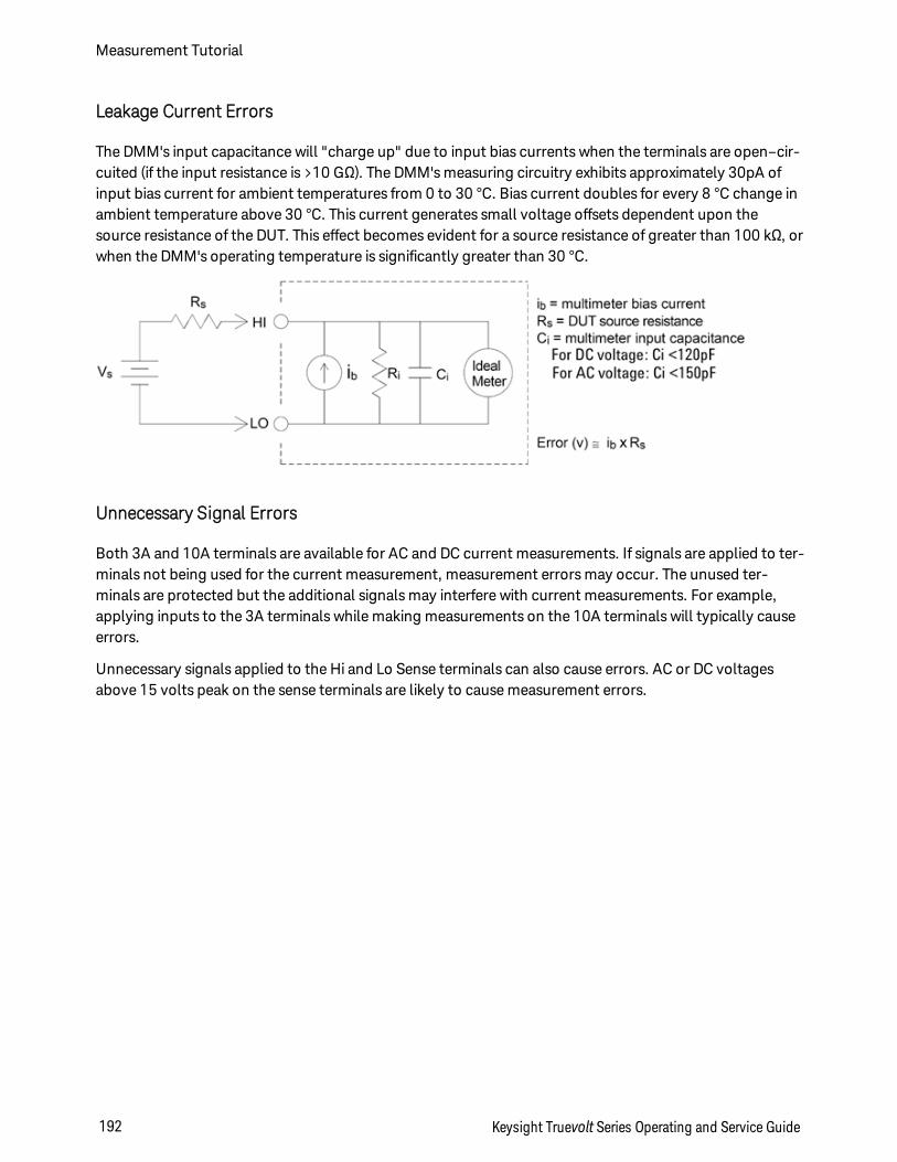
Leakage Current Errors
The DMM's input capacitance will "charge up" due to input bias currents when the terminals are open–cir-cuited (if the input resistance is >10 GΩ). The DMM's measuring circuitry exhibits approximately 30pA ofinput bias current for ambient temperatures from 0 to 30 °C. Bias current doubles for every 8 °C change inambient temperature above 30 °C. This current generates small voltage offsets dependent upon thesource resistance of the DUT. This effect becomes evident for a source resistance of greater than 100 kΩ, orwhen the DMM's operating temperature is significantly greater than 30 °C.
Unnecessary Signal Errors
Both 3A and 10A terminals are available for AC and DC current measurements. If signals are applied to ter-minals not being used for the current measurement, measurement errors may occur. The unused ter-minals are protected but the additional signals may interfere with current measurements. For example,applying inputs to the 3A terminals while making measurements on the 10A terminals will typically causeerrors.
Unnecessary signals applied to the Hi and Lo Sense terminals can also cause errors. AC or DC voltagesabove 15 volts peak on the sense terminals are likely to cause measurement errors.
Measurement Tutorial
192 Keysight Truevolt Series Operating and Service Guide
How Sample Rate/Interval is Determined
The DMM always attempts to make the sample interval greater than the expected time required to take themeasurements, whether in continuous, data log, or digitize mode. A number of settings go into the cal-culation of the minimum allowable sample interval. These settings include the measurement function,NPLC, aperture, autorange, autozero, offset compensation, AC filter, TC open check and gate time. Forexample, when autorange is on, the assumption is that no more than one range change will be required. Ifmore than one level of change occurs, the measurement may be delayed and an error will be issued.
When you change any of these settings, the sample interval (sample timer in continuous mode, sampleinterval in data log or digitize mode) is increased to be greater than the calculated measurement time. Inthe continuous and data log modes, attempting to reduce the sample interval below the calculated valueresults in an error message. You must then choose among the various ways you can achieve a smallermeasurement time to achieve the smaller sample interval, such as decreasing the NPLC setting. For digit-izing, the emphasis is on high sample rates and all settings except aperture/NPLC are fixed to achieve min-imum measurement time. NPLC and aperture are automatically set to their minimum values upon enteringdigitize mode. If you set NPLC or aperture to greater values, the sample interval will be increased (or thesample rate decreased) to accommodate the longer measurement. However, in digitize mode, unlike con-tinuous and data log modes, if you subsequently decrease the sample interval (or increase the samplerate), the NPLC or aperture will be reduced as needed.
Another way to put it is that for continuous and data log modes, sample timer/interval is always con-trolled by the other measurement settings. In digitize mode, the sample timer/interval, NPLC, and aper-ture have equal control; changing any one setting can change the other settings.
Keysight Truevolt Series Operating and Service Guide 193
Measurement Tutorial
SCPI Programming ReferenceThis section contains information to help you program the Keysight Truevolt Series digital multimetersover a remote interface using the SCPI programming language.
Introduction to the SCPI Language
Commands by Subsystem
Command Quick Reference
SCPI Error Messages
Power-On and Reset State
Related Information
IO Libraries and Instrument Drivers
The Keysight IO Libraries Suite software and installation instructions are on the Keysight AutomationReady CD-ROM provided with your instrument (optional for 34460A).
Keysight Truevolt Series Documentation
Web Interface
The 34461A/65A/70A and the 34460A (with option 34460A-LAN or option 3446LANU) have a Web Inter-face built into the instrument. You can use this interface over LAN for remote access and control of theinstrument via a Web browser. See Web Interface for details.
SCPI Programming Reference
194 Keysight Truevolt Series Operating and Service Guide
Introduction to the SCPI Language
SCPI (Standard Commands for Programmable Instruments) is an ASCII-based programming language fortest and measurement instruments. SCPI commands use a hierarchical structure known as a tree system.Associated commands are grouped under a common node or root, thus forming subsystems. A portion ofthe SENSe subsystem illustrates this, below.
SENSe: VOLTage: DC:RANGe <range>|MIN|MAX|DEF DC:RANGe? [MINimum|MAXimum|DEFault]
SENSe is the root keyword of the command, VOLTage is a second-level keyword, and DC is a third-levelkeyword. A colon ( : ) separates consecutive keywords.
Syntax Conventions
The command syntax format is illustrated below:
VOLTage:DC:RANGe <range>|MIN|MAX|DEF
Most commands (and some parameters) are a mixture of upper- and lower-case letters. The upper-case let-ters indicate the command's abbreviated spelling, which yields shorter program lines. For better programreadability, use the long form.
For example, consider the keyword VOLTage, above. You can type VOLT or VOLTage in any combination ofupper- or lower-case letters. Therefore, VolTaGe, volt and Volt are all acceptable. Other forms, such asVOL and VOLTAG, generate errors.
Braces ( ) enclose the parameter choices. The braces are not sent with the command string.
A vertical bar ( | ) separates parameter choices. For example, <range>|MIN|MAX|DEF in the above com-mand indicates that you can specify a numeric range parameter, or "MIN", "MAX" or "DEF". The bar is notsent with the command string.
Angle brackets ( < > ) indicate that you must specify a value for the enclosed parameter. For example, theabove syntax statement shows the <range> parameter in angle brackets. Do not send the brackets withthe command string. You must specify a value for the parameter (for example "VOLT:DC:RANG 10") unlessyou select one of the other options shown in the syntax (for example "VOLT:DC:RANG MIN").
Optional parameters are enclosed in square brackets ( [ ] ). The brackets are not sent with the commandstring. If you do not specify a value for an optional parameter, the instrument uses a default value.
Keysight Truevolt Series Operating and Service Guide 195
SCPI Programming Reference
Command Separators
A colon ( : ) separates consecutive keywords. You must insert a blank space to separate a parameter from acommand keyword. If a command requires more than one parameter, separate adjacent parameters usinga comma:
CONF:VOLT:DC 10,0.003
A semicolon ( ; ) separates commands within the same subsystem and can also minimize typing. Forexample, the following string:
TRIG:SOUR EXT;COUNT 10
is equivalent to the following two commands:
TRIG:SOUR EXTTRIG:COUNT 10
Use a colon and a semicolon to link commands from different subsystems. For example, in the followingexample, an error is generated if you do not use both the colon and semicolon:
TRIG:COUN MIN;:SAMP:COUN MIN
Using the MIN, MAX and DEF Parameters
For many commands, you can substitute "MIN" or "MAX" in place of a parameter. In some cases you mayalso substitute "DEF". For example, consider The following example:
VOLTage:DC:RANGe <range>|MIN|MAX|DEF
Instead of selecting a specific value for the <range> parameter, you can substitute MIN to set the range toits minimum value, MAX to set the range to its maximum value or DEF to set the range to its default value.
Querying Parameter Settings
You can query the current value of most parameters by adding a question mark ( ? ) to the command. Forexample, The following example sets the trigger count to 10 measurements:
TRIG:COUN 10
You can then query the count value by sending:
TRIG:COUN?
You can also query the minimum or maximum count allowed as follows:
TRIG:COUN? MINTRIG:COUN? MAX
SCPI Programming Reference
196 Keysight Truevolt Series Operating and Service Guide
SCPI Command Terminators
A command string sent to the instrument must terminate with a <new line> (<NL>) character (ASCIIdecimal 10). The IEEE-488 EOI (End-Or-Identify) message is interpreted as a <NL> character and can beused to terminate a command string in place of a <NL> character. A <carriage return> followed by a <NL>is also accepted. Command string termination always resets the current SCPI command path to the rootlevel.
For every SCPI message that includes a query and is sent to the instrument, the instru-ment terminates the returned response with a <NL> or line-feed character (EOI). Forexample, if R? is sent, the response is terminated with a <NL> after the block of data thatis returned. If a SCPI message includes multiple queries separated by semicolons (forexample "ROUTe:TERMinals?;R?"), the returned response is again terminated by a <NL>after the response to the last query. In either case, the program must read this <NL> inthe response before another command is sent to the instrument or an error occurs.
IEEE-488.2 Common Commands
The IEEE-488.2 standard defines a set of common commands that perform functions such as reset, self-test and status operations. Common commands always begin with an asterisk ( * ), are three characters inlength and may include one or more parameters. The command keyword is separated from the first para-meter by a blank space. Use a semicolon ( ; ) to separate multiple commands as shown below:
*RST; *CLS; *ESE 32; *OPC?
SCPI Parameter Types
The SCPI language defines several data formats to be used in program messages and response messages.
Numeric Parameters
Commands that require numeric parameters accept all commonly used decimal representations of num-bers including optional signs, decimal points, and scientific notation. Special values for numeric para-meters such as MIN, MAX and DEF are also accepted. You can also send engineering unit suffixes withnumeric parameters (e.g., M, k, m or u). If a command accepts only certain specific values, the instrumentrounds the input numeric parameters to the accepted values. The following command requires a numericparameter for the range value:
VOLTage:DC:RANGe <range>|MIN|MAX|DEF
Because the SCPI parser is case-insensitive, there is some confusion over the letter "M"(or "m"). For your convenience, the instrument interprets "mV" (or "MV") as millivolts, but"MHZ" (or "mhz") as megahertz. Likewise "MΩ" (or "mΩ") is interpreted as megΩ. Youcan use the prefix "MA" for mega. For example, "MAV" is interpreted as megavolts.
Keysight Truevolt Series Operating and Service Guide 197
SCPI Programming Reference
Discrete Parameters
Discrete parameters are used to program settings that have a limited number of values (like IMMediate,EXTernal or BUS). They have a short form and a long form just like command keywords. You can mixupper- and lower-case letters. Query responses always return the short form in all upper-case letters. Thefollowing example requires a discrete parameters for the temperature units:
UNIT:TEMPerature C|F|K
Boolean Parameters
Boolean parameters represent a single binary condition that is either true or false. For a false condition,the instrument accepts "OFF" or "0". For a true condition, the instrument accepts "ON" or "1". When youquery a Boolean setting, the instrument returns "0" or "1". The following example requires a Boolean para-meter:
DISPlay:STATe ON|1|OFF|0
ASCII String Parameters
String parameters can contain virtually any set of ASCII characters. A string must begin and end withmatching quotes; either with a single quote or a double quote. You can include the quote delimiter as partof the string by typing it twice without any characters in between. The following command uses a stringparameter:
DISPlay:TEXT <quoted string>
For example, The following example displays the message "WAITING..." on the instrument's front panel(the quotes are not displayed).
DISP:TEXT "WAITING..."
You can also display the same message using The following example with single quotes.
DISP:TEXT 'WAITING...'
SCPI Programming Reference
198 Keysight Truevolt Series Operating and Service Guide
Using Device Clear
Device Clear is an IEEE-488 low-level bus message that you can use to return the instrument to a respons-ive state. Different programming languages and IEEE-488 interface cards provide access to this capabilitythrough their own unique commands. The status registers, the error queue, and all configuration statesare left unchanged when a Device Clear message is received.
Device Clear performs the following actions:
l If a measurement is in progress, it is aborted.
l The instrument returns to the trigger "idle" state.
l The instrument's input and output buffers are cleared.
l The instrument is prepared to accept a new command string.
l An overlapped command, if any, is terminated with no "Operation Complete" indication (applies toINIT).
The ABORt command is the recommended method to terminate a measurement.
Commands by Subsystem
ABORt
CALCulate:CLEar[:IMMediate]
CALCulate:AVERage Subsystem
CALCulate:LIMit Subsystem
CALCulate:SCALe Subsystem
CALCulate:SMOothing Subsystem
CALCulate:TCHart[:STATe]
CALCulate:TRANsform:HISTogram Subsystem
CALibration Subsystem
CONFigure Subsystem
DATA Subsystem
DISPlay Subsystem
FETCh?
FORMat Subsystem
HCOPy Subsystem
IEEE 488.2 Common Commands
INITiate[:IMMediate]
LXI Subsystem
Keysight Truevolt Series Operating and Service Guide 199
SCPI Programming Reference
MEASure Subsystem
MMEMory Subsystem - Data Transfer Commands
MMEMory Subsystem - General Purpose File Management
MMEMory Subsystem - STATe and PREFerence Files
OUTPut:TRIGger:SLOPe
R?
READ?
ROUTe:TERMinals?
SAMPle Subsystem
[SENSe:]CAPacitance Subsystem
[SENSe:]CURRent Subsystem
[SENSe:]DATA2 Subsystem
[SENSe:]FREQuency|PERiod Subsystem
[SENSe:]RESistance|FRESistance Subsystem
[SENSe:]TEMPerature Subsystem
[SENSe:]VOLTage Subsystem
STATus Subsystem
SYSTem Subsystem - General Purpose Commands
SYSTem Subsystem - I/O Configuration
SYSTem:LICense Subsystem
SYSTem:LOCK Subsystem
TEST:ALL?
TRIGger Subsystem
UNIT:TEMPerature
SCPI Programming Reference
200 Keysight Truevolt Series Operating and Service Guide

ABORt
Aborts a measurement in progress, returning the instrument to the trigger idle state.
Parameter Typical Return
(none) (none)
Abort a measurement in progress:
ABORt
l Use this to abort a measurement when the instrument is waiting for a trigger, or for aborting a longmeasurement or series of measurements.
Keysight Truevolt Series Operating and Service Guide 201
SCPI Programming Reference
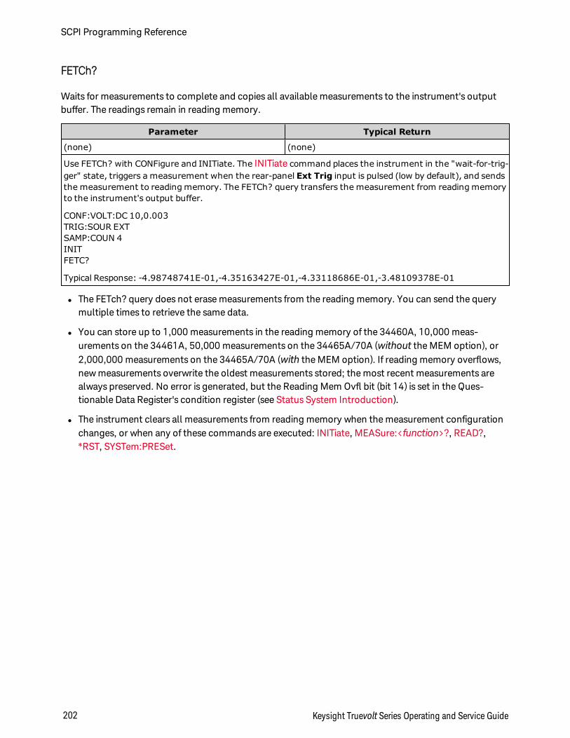
FETCh?
Waits for measurements to complete and copies all available measurements to the instrument's outputbuffer. The readings remain in reading memory.
Parameter Typical Return
(none) (none)
Use FETCh? with CONFigure and INITiate. The INITiate command places the instrument in the "wait-for-trig-ger" state, triggers a measurement when the rear-panel Ext Trig input is pulsed (low by default), and sendsthe measurement to reading memory. The FETCh? query transfers the measurement from reading memoryto the instrument's output buffer.
CONF:VOLT:DC 10,0.003TRIG:SOUR EXTSAMP:COUN 4INITFETC?
Typical Response: -4.98748741E-01,-4.35163427E-01,-4.33118686E-01,-3.48109378E-01
l The FETch? query does not erase measurements from the reading memory. You can send the querymultiple times to retrieve the same data.
l You can store up to 1,000 measurements in the reading memory of the 34460A, 10,000 meas-urements on the 34461A, 50,000 measurements on the 34465A/70A (without the MEM option), or2,000,000 measurements on the 34465A/70A (with the MEM option). If reading memory overflows,new measurements overwrite the oldest measurements stored; the most recent measurements arealways preserved. No error is generated, but the Reading Mem Ovfl bit (bit 14) is set in the Ques-tionable Data Register's condition register (see Status System Introduction).
l The instrument clears all measurements from reading memory when the measurement configurationchanges, or when any of these commands are executed: INITiate, MEASure:<function>?, READ?,*RST, SYSTem:PRESet.
SCPI Programming Reference
202 Keysight Truevolt Series Operating and Service Guide
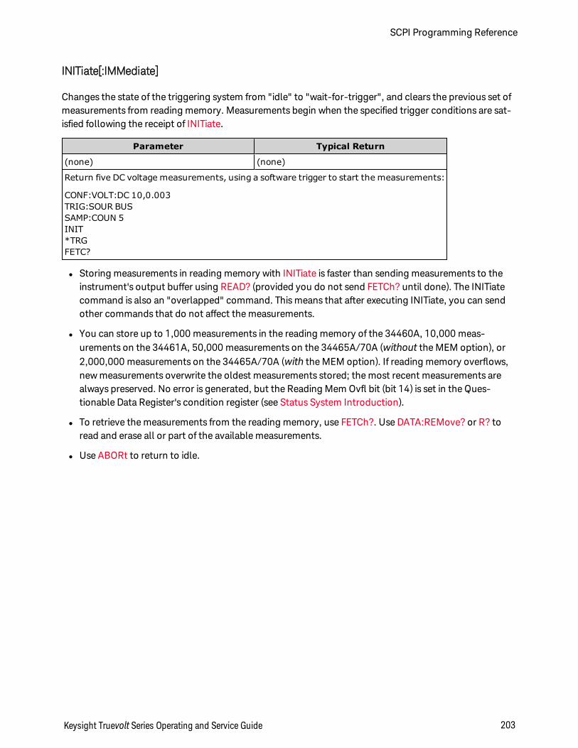
INITiate[:IMMediate]
Changes the state of the triggering system from "idle" to "wait-for-trigger", and clears the previous set ofmeasurements from reading memory. Measurements begin when the specified trigger conditions are sat-isfied following the receipt of INITiate.
Parameter Typical Return
(none) (none)
Return five DC voltage measurements, using a software trigger to start the measurements:
CONF:VOLT:DC 10,0.003TRIG:SOUR BUSSAMP:COUN 5INIT*TRGFETC?
l Storing measurements in reading memory with INITiate is faster than sending measurements to theinstrument's output buffer using READ? (provided you do not send FETCh? until done). The INITiatecommand is also an "overlapped" command. This means that after executing INITiate, you can sendother commands that do not affect the measurements.
l You can store up to 1,000 measurements in the reading memory of the 34460A, 10,000 meas-urements on the 34461A, 50,000 measurements on the 34465A/70A (without the MEM option), or2,000,000 measurements on the 34465A/70A (with the MEM option). If reading memory overflows,new measurements overwrite the oldest measurements stored; the most recent measurements arealways preserved. No error is generated, but the Reading Mem Ovfl bit (bit 14) is set in the Ques-tionable Data Register's condition register (see Status System Introduction).
l To retrieve the measurements from the reading memory, use FETCh?. Use DATA:REMove? or R? toread and erase all or part of the available measurements.
l Use ABORt to return to idle.
Keysight Truevolt Series Operating and Service Guide 203
SCPI Programming Reference
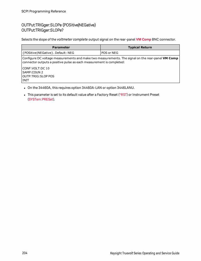
OUTPut:TRIGger:SLOPe POSitive|NEGativeOUTPut:TRIGger:SLOPe?
Selects the slope of the voltmeter complete output signal on the rear-panel VM Comp BNC connector.
Parameter Typical Return
POSitive|NEGative. Default: NEG POS or NEG
Configure DC voltage measurements and make two measurements. The signal on the rear-panel VM Compconnector outputs a positive pulse as each measurement is completed:
CONF:VOLT:DC 10SAMP:COUN 2OUTP:TRIG:SLOP POSINIT
l On the 34460A, this requires option 34460A-LAN or option 3446LANU.
l This parameter is set to its default value after a Factory Reset (*RST) or Instrument Preset(SYSTem:PRESet).
SCPI Programming Reference
204 Keysight Truevolt Series Operating and Service Guide
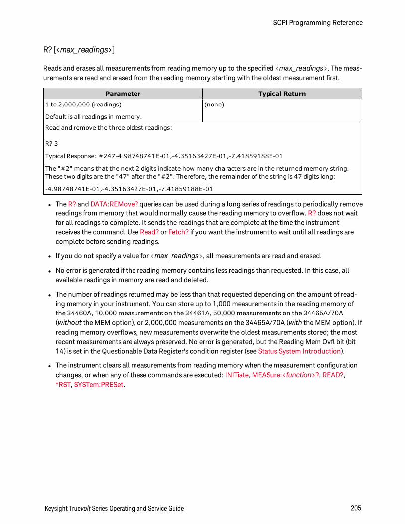
R? [<max_readings>]
Reads and erases all measurements from reading memory up to the specified <max_readings>. The meas-urements are read and erased from the reading memory starting with the oldest measurement first.
Parameter Typical Return
1 to 2,000,000 (readings)
Default is all readings in memory.
(none)
Read and remove the three oldest readings:
R? 3
Typical Response: #247-4.98748741E-01,-4.35163427E-01,-7.41859188E-01
The "#2" means that the next 2 digits indicate how many characters are in the returned memory string.These two digits are the "47" after the "#2". Therefore, the remainder of the string is 47 digits long:
-4.98748741E-01,-4.35163427E-01,-7.41859188E-01
l The R? and DATA:REMove? queries can be used during a long series of readings to periodically removereadings from memory that would normally cause the reading memory to overflow. R? does not waitfor all readings to complete. It sends the readings that are complete at the time the instrumentreceives the command. Use Read? or Fetch? if you want the instrument to wait until all readings arecomplete before sending readings.
l If you do not specify a value for <max_readings>, all measurements are read and erased.
l No error is generated if the reading memory contains less readings than requested. In this case, allavailable readings in memory are read and deleted.
l The number of readings returned may be less than that requested depending on the amount of read-ing memory in your instrument. You can store up to 1,000 measurements in the reading memory ofthe 34460A, 10,000 measurements on the 34461A, 50,000 measurements on the 34465A/70A(without the MEM option), or 2,000,000 measurements on the 34465A/70A (with the MEM option). Ifreading memory overflows, new measurements overwrite the oldest measurements stored; the mostrecent measurements are always preserved. No error is generated, but the Reading Mem Ovfl bit (bit14) is set in the Questionable Data Register's condition register (see Status System Introduction).
l The instrument clears all measurements from reading memory when the measurement configurationchanges, or when any of these commands are executed: INITiate, MEASure:<function>?, READ?,*RST, SYSTem:PRESet.
Keysight Truevolt Series Operating and Service Guide 205
SCPI Programming Reference
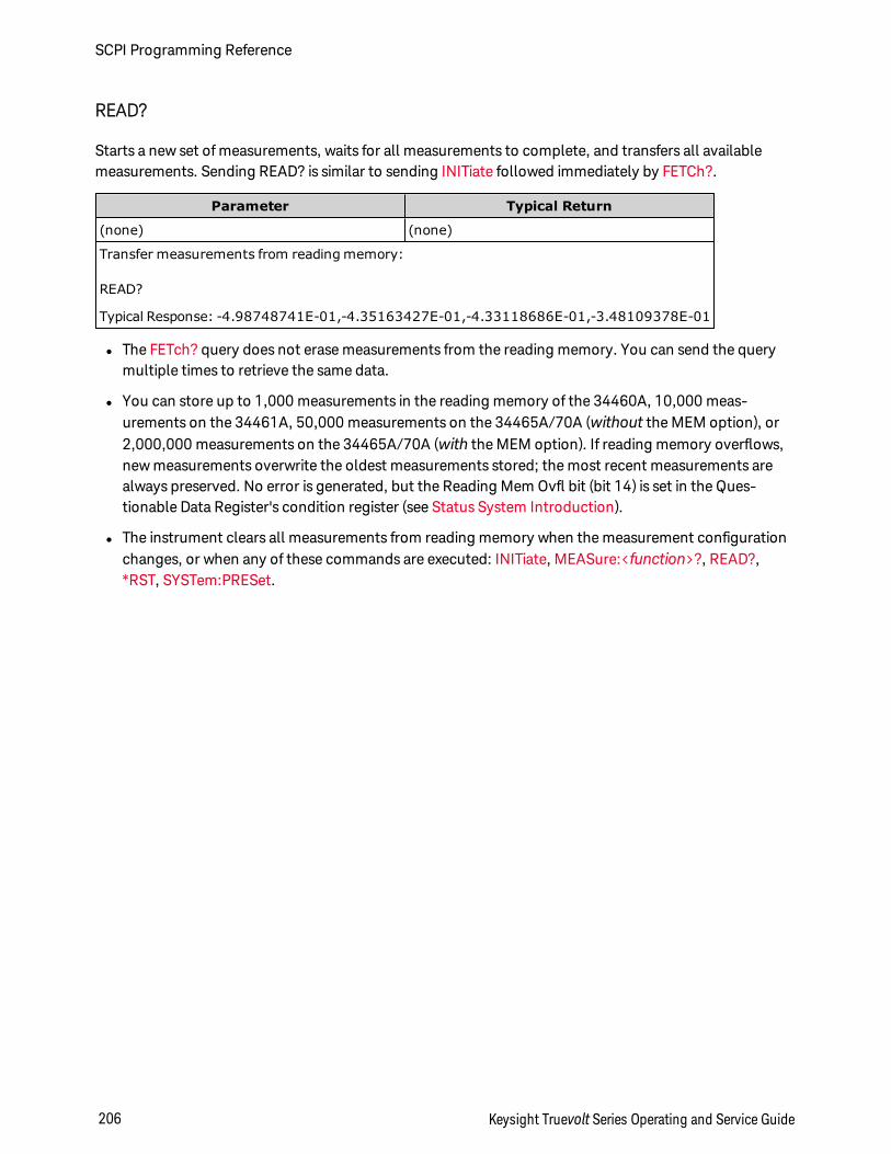
READ?
Starts a new set of measurements, waits for all measurements to complete, and transfers all availablemeasurements. Sending READ? is similar to sending INITiate followed immediately by FETCh?.
Parameter Typical Return
(none) (none)
Transfer measurements from reading memory:
READ?
Typical Response: -4.98748741E-01,-4.35163427E-01,-4.33118686E-01,-3.48109378E-01
l The FETch? query does not erase measurements from the reading memory. You can send the querymultiple times to retrieve the same data.
l You can store up to 1,000 measurements in the reading memory of the 34460A, 10,000 meas-urements on the 34461A, 50,000 measurements on the 34465A/70A (without the MEM option), or2,000,000 measurements on the 34465A/70A (with the MEM option). If reading memory overflows,new measurements overwrite the oldest measurements stored; the most recent measurements arealways preserved. No error is generated, but the Reading Mem Ovfl bit (bit 14) is set in the Ques-tionable Data Register's condition register (see Status System Introduction).
l The instrument clears all measurements from reading memory when the measurement configurationchanges, or when any of these commands are executed: INITiate, MEASure:<function>?, READ?,*RST, SYSTem:PRESet.
SCPI Programming Reference
206 Keysight Truevolt Series Operating and Service Guide
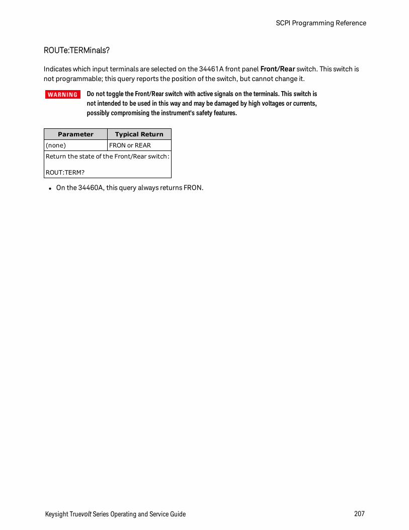
ROUTe:TERMinals?
Indicates which input terminals are selected on the 34461A front panel Front/Rear switch. This switch isnot programmable; this query reports the position of the switch, but cannot change it.
Do not toggle the Front/Rear switch with active signals on the terminals. This switch isnot intended to be used in this way and may be damaged by high voltages or currents,possibly compromising the instrument's safety features.
Parameter Typical Return
(none) FRON or REAR
Return the state of the Front/Rear switch:
ROUT:TERM?
l On the 34460A, this query always returns FRON.
Keysight Truevolt Series Operating and Service Guide 207
SCPI Programming Reference
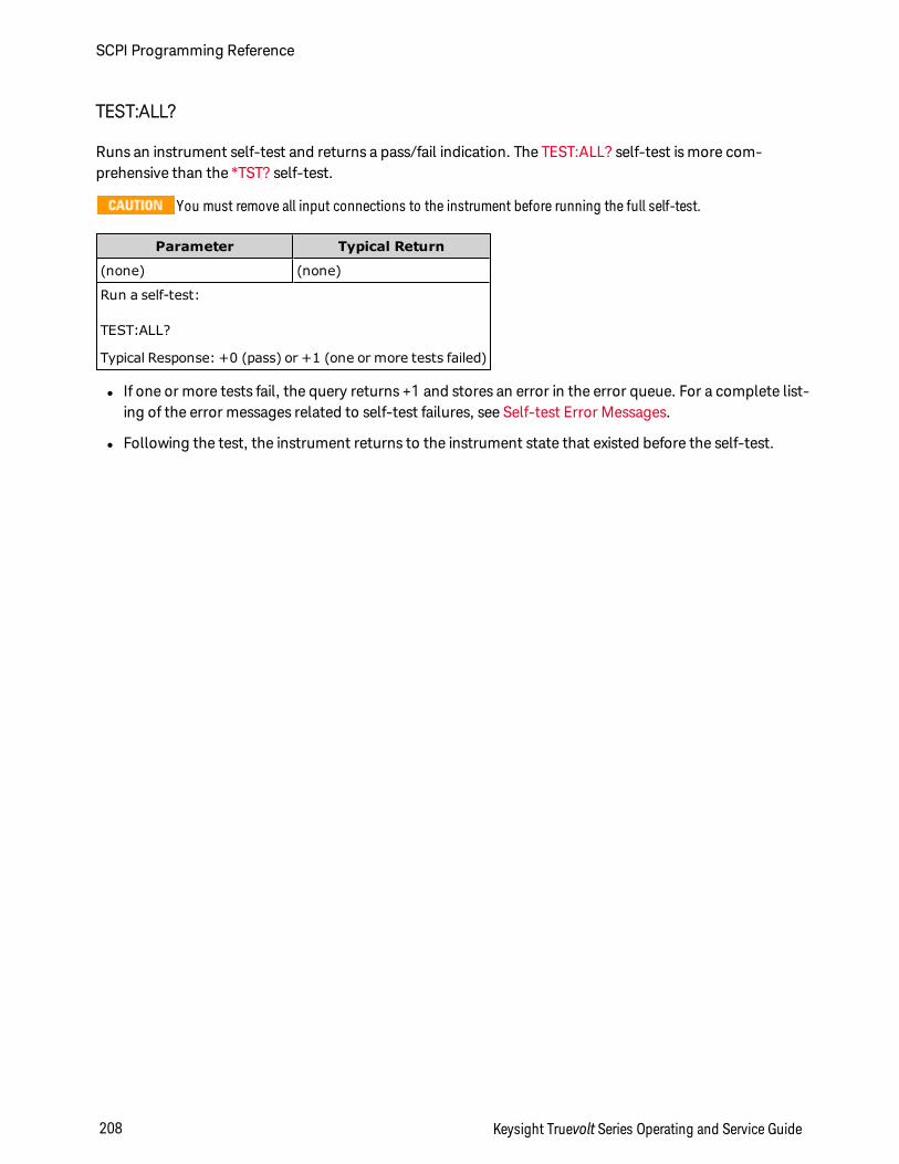
TEST:ALL?
Runs an instrument self-test and returns a pass/fail indication. The TEST:ALL? self-test is more com-prehensive than the *TST? self-test.
You must remove all input connections to the instrument before running the full self-test.
Parameter Typical Return
(none) (none)
Run a self-test:
TEST:ALL?
Typical Response: +0 (pass) or +1 (one or more tests failed)
l If one or more tests fail, the query returns +1 and stores an error in the error queue. For a complete list-ing of the error messages related to self-test failures, see Self-test Error Messages.
l Following the test, the instrument returns to the instrument state that existed before the self-test.
SCPI Programming Reference
208 Keysight Truevolt Series Operating and Service Guide
UNIT:TEMPerature C|F|KUNIT:TEMPerature?
Selects the units (°C, °F or Kelvin) to be used for all temperature measurements except theSYSTem:TEMPerature? query.
Parameter Typical Return
C|F|K. Default: C. C, F, or K
Make a four-wire RTD measurement and return the result in °F:
UNIT:TEMP FMEAS:TEMP? FRTD
Typical Response: +6.82320000E+01
l The command also accepts CEL or FAR, but the query returns C or F.
l This parameter is set to its default value after a Factory Reset (*RST) or Instrument Preset(SYSTem:PRESet).
See Also
CONFigure:TEMPerature
MEASure:TEMPerature?
[SENSe:]FUNCtion[:ON]
Keysight Truevolt Series Operating and Service Guide 209
SCPI Programming Reference
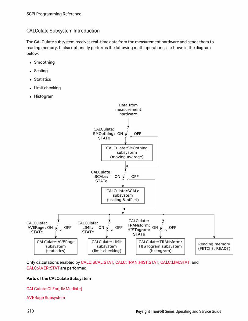
CALCulate Subsystem Introduction
The CALCulate subsystem receives real-time data from the measurement hardware and sends them toreading memory. It also optionally performs the following math operations, as shown in the diagrambelow:
l Smoothing
l Scaling
l Statistics
l Limit checking
l Histogram
Only calculations enabled by CALC:SCAL:STAT, CALC:TRAN:HIST:STAT, CALC:LIM:STAT, andCALC:AVER:STAT are performed.
Parts of the CALCulate Subsystem
CALCulate:CLEar[:IMMediate]
AVERage Subsystem
SCPI Programming Reference
210 Keysight Truevolt Series Operating and Service Guide

HISTogram Subsystem
LIMit Subsystem
SCALing Subsystem
SMOothing Subsystem
Keysight Truevolt Series Operating and Service Guide 211
SCPI Programming Reference
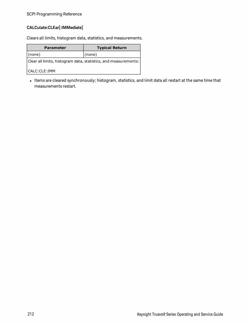
CALCulate:CLEar[:IMMediate]
Clears all limits, histogram data, statistics, and measurements.
Parameter Typical Return
(none) (none)
Clear all limits, histogram data, statistics, and measurements:
CALC:CLE:IMM
l Items are cleared synchronously; histogram, statistics, and limit data all restart at the same time thatmeasurements restart.
SCPI Programming Reference
212 Keysight Truevolt Series Operating and Service Guide
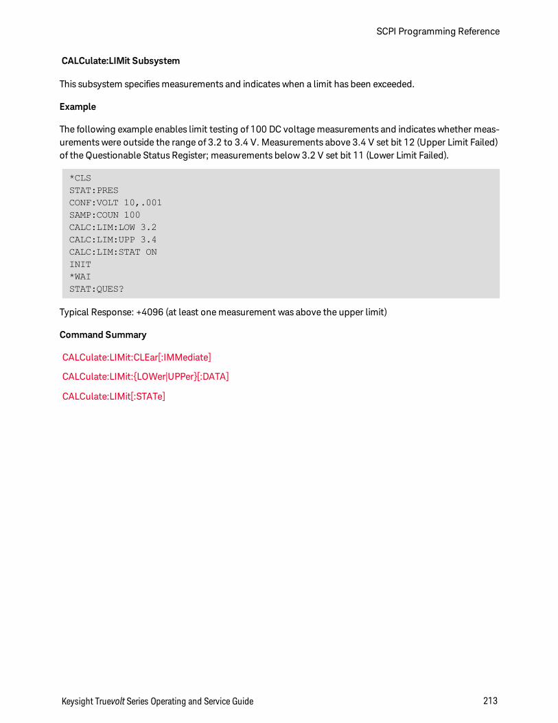
CALCulate:LIMit Subsystem
This subsystem specifies measurements and indicates when a limit has been exceeded.
Example
The following example enables limit testing of 100 DC voltage measurements and indicates whether meas-urements were outside the range of 3.2 to 3.4 V. Measurements above 3.4 V set bit 12 (Upper Limit Failed)of the Questionable Status Register; measurements below 3.2 V set bit 11 (Lower Limit Failed).
*CLSSTAT:PRESCONF:VOLT 10,.001SAMP:COUN 100CALC:LIM:LOW 3.2CALC:LIM:UPP 3.4CALC:LIM:STAT ONINIT*WAISTAT:QUES?
Typical Response: +4096 (at least one measurement was above the upper limit)
Command Summary
CALCulate:LIMit:CLEar[:IMMediate]
CALCulate:LIMit:LOWer|UPPer[:DATA]
CALCulate:LIMit[:STATe]
Keysight Truevolt Series Operating and Service Guide 213
SCPI Programming Reference
CALCulate:LIMit:CLEar[:IMMediate]
Clears front panel indications of limits being exceeded and clears bit 11 ("Lower Limit Failed") and bit 12("Upper Limit Failed") in the Condition Register of the Questionable Data Register event register group.The corresponding event register bits are unaffected.
A condition register continuously monitors the state of the instrument. Condition register bits are updatedin real time; they are neither latched nor buffered.
An event register is a read-only register that latches events from the condition register. While an event bitis set, subsequent events corresponding to that bit are ignored.
Parameter Typical Return
(none) (none)
Clear the limit test results:
CALC:LIM:CLE
l Does not clear measurements in reading memory.
l The instrument clears front panel indications of limits being exceeded and clears bits 11 and 12 in theQuestionable Data Register when the measurement function changes, or when any of the followingcommands is executed:
CALCulate:LIMit:STATe ON
INITiate
MEASure:<function>?
READ?
CALCulate:LIMit:CLEar
*RST
SYSTem:PRESet
l To clear statistics, limits, histogram data, and measurement data, use CALCulate:CLEar[:IMMediate].
SCPI Programming Reference
214 Keysight Truevolt Series Operating and Service Guide
CALCulate:LIMit:LOWer|UPPer[:DATA] <value>|MIN|MAX|DEFCALCulate:LIMit:LOWer|UPPer[:DATA]? [MIN|MAX|DEF]
Sets an upper or lower limit.
Parameter Typical Return
-1.0E+15 to -1.0E-15,or0.0 (default)or+1.0E-15 to 1.0E+15
+1.00000000E+00
See Example.
l You can assign a lower limit, an upper limit or both. Do not set the lower limit above the upper limit.
l Limit crossing: If a measurement is less than the specified lower limit, bit 11 ("Lower Limit Failed") isset in the Questionable Data Condition Register. A measurement greater than the specified upper limitsets bit 12 ("Upper Limit Failed"). See STATus Subsystem Introduction for further information.
l CONFigure resets both limits to 0.
l This parameter is set to its default value after a Factory Reset (*RST) or Instrument Preset(SYSTem:PRESet).
Keysight Truevolt Series Operating and Service Guide 215
SCPI Programming Reference
CALCulate:LIMit[:STATe] ON|1|OFF|0CALCulate:LIMit[:STATe]?
Enables or disables limit testing.
Parameter Typical Return
ON|1|OFF|0. Default: OFF. 0 (OFF) or 1 (ON)
See Example.
l The instrument clears front panel indications of limits being exceeded and clears bits 11 and 12 in theQuestionable Data Register when the measurement function changes, or when any of the followingcommands is executed:
CALCulate:LIMit:STATe ON
INITiate
MEASure:<function>?
READ?
CALCulate:LIMit:CLEar
*RST
SYSTem:PRESet
l The instrument turns this setting OFF when the measurement function is changed or after *RST orSYSTem:PRESet.
SCPI Programming Reference
216 Keysight Truevolt Series Operating and Service Guide
CALCulate:TRANsform:HISTogram Subsystem
The HISTogram subsystem configures the histogram display. The instrument clears histogram data whenthe measurement function changes and when any of the following commands are sent:
CALCulate:TRANsform:HISTogram:CLEar[:IMMediate]
CALCulate:TRANsform:HISTogram:POINts
CALCulate:TRANsform:HISTogram:RANGe:AUTO
CALCulate:TRANsform:HISTogram:RANGe:LOWer|UPPer
CALCulate:TRANsform:HISTogram[:STATe]
INITiate[:IMMediate]
MEASure:<function>?
READ?
*RST
SYSTem:PRESet
Command Summary
CALCulate:TRANsform:HISTogram:ALL?
CALCulate:TRANsform:HISTogram:CLEar[:IMMediate]
CALCulate:TRANsform:HISTogram:COUNt?
CALCulate:TRANsform:HISTogram:DATA?
CALCulate:TRANsform:HISTogram:POINts
CALCulate:TRANsform:HISTogram:RANGe:AUTO
CALCulate:TRANsform:HISTogram:RANGe:LOWer|UPPer
CALCulate:TRANsform:HISTogram[:STATe]
Keysight Truevolt Series Operating and Service Guide 217
SCPI Programming Reference
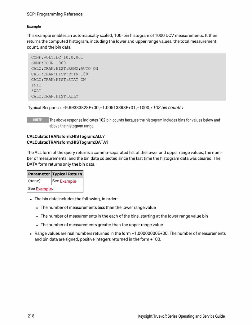
Example
This example enables an automatically scaled, 100-bin histogram of 1000 DCV measurements. It thenreturns the computed histogram, including the lower and upper range values, the total measurementcount, and the bin data.
CONF:VOLT:DC 10,0.001SAMP:COUN 1000CALC:TRAN:HIST:RANG:AUTO ONCALC:TRAN:HIST:POIN 100CALC:TRAN:HIST:STAT ONINIT*WAICALC:TRAN:HIST:ALL?
Typical Response: +9.99383828E+00,+1.00513398E+01,+1000,<102 bin counts>
The above response indicates 102 bin counts because the histogram includes bins for values below andabove the histogram range.
CALCulate:TRANsform:HISTogram:ALL?CALCulate:TRANsform:HISTogram:DATA?
The ALL form of the query returns a comma-separated list of the lower and upper range values, the num-ber of measurements, and the bin data collected since the last time the histogram data was cleared. TheDATA form returns only the bin data.
Parameter Typical Return
(none) See Example.
See Example.
l The bin data includes the following, in order:
l The number of measurements less than the lower range value
l The number of measurements in the each of the bins, starting at the lower range value bin
l The number of measurements greater than the upper range value
l Range values are real numbers returned in the form +1.00000000E+00. The number of measurementsand bin data are signed, positive integers returned in the form +100.
SCPI Programming Reference
218 Keysight Truevolt Series Operating and Service Guide
CALCulate:TRANsform:HISTogram:CLEar[:IMMediate]
Clears the histogram data and restarts histogram ranging if it is enabled (CALCu-late:TRANsform:HISTogram:RANGe:AUTO ON).
Parameter Typical Return
(none) (none)
Clear the histogram data:
CALC:TRAN:HIST:CLE
l Does not clear measurements in reading memory.
l To clear statistics, limits, histogram data, and measurement data, use CALCulate:CLEar[:IMMediate].
CALCulate:TRANsform:HISTogram:COUNt?
Returns the number of measurements collected since the last time the histogram was cleared.
Parameter TypicalReturn
(none) +87
Return the number of measurements used to compute the current histogram:
CALC:TRAN:HIST:COUN?
CALCulate:TRANsform:HISTogram:POINts <value>|MIN|MAX|DEFCALCulate:TRANsform:HISTogram:POINts? [MIN|MAX|DEF]
Sets the number of bins between the lower and upper range values for the histogram. Two additional binsalways exist: one for measurements below the lower range and one for measurements above the upperrange.
Parameter Typical Return
10|20|40|100|200|400|MIN|MAX|DEF. Default: 100. +100
See Example.
l You can specify the lower and upper range values using CALCulate:TRANsform:HISTogram:RANGe:LOWer|UPPer. Lower and upper range values are computed automatically if CALCu-late:TRANsform:HISTogram:RANGe:AUTO is ON.
l This parameter is set to its default value after a Factory Reset (*RST) or Instrument Preset(SYSTem:PRESet).
Keysight Truevolt Series Operating and Service Guide 219
SCPI Programming Reference
CALCulate:TRANsform:HISTogram:RANGe:AUTO ON|1|OFF|0CALCulate:TRANsform:HISTogram:RANGe:AUTO?
Enables or disables automatic selection of the histogram's lower and upper range values.
Parameter Typical Return
ON|1|OFF|0. Default: ON. 0 (OFF) or 1 (ON)
See Example.
l ON: the instrument uses the first 1,000 measurements to set the lower and upper range values.
l OFF: the lower and upper range values are specified by CALCulate:TRANsform:HISTogram:RANGe:LOWer|UPPer.
l Setting the lower or upper range value (CALCulate:TRANsform:HISTogram:RANGe:LOWer|UPPer) dis-ables automatic selection of the lower and upper range values (CALCu-late:TRANsform:HISTogram:RANGe:AUTO OFF).
l The instrument restarts automatic range value selection (if enabled) when INITiate, MEASure? orREAD? is executed.
l This parameter is set to its default value after a Factory Reset (*RST) or Instrument Preset(SYSTem:PRESet).
CALCulate:TRANsform:HISTogram:RANGe:LOWer|UPPer <value>|MIN|MAX|DEFCALCulate:TRANsform:HISTogram:RANGe:LOWer|UPPer? [MIN|MAX|DEF]
Sets the histogram's lower and upper range values. Setting the lower or upper range value (CALCu-late:TRANsform:HISTogram:RANGe:LOWer|UPPer) disables automatic selection of the lower and upperrange values (CALCulate:TRANsform:HISTogram:RANGe:AUTO OFF).
Parameter Typical Return
-1.0E+15 to -1.0E-15,or0.0 (default)or+1.0E-15 to 1.0E+15
+1.00000000E+06
See Example.
l If automatic range value selection is enabled (CALCulate:TRANsform:HISTogram:RANGe:AUTO ON),the query returns the computed range value. If no histogram data exists, 9.91E37 (Not a Number) isreturned.
l Lower and upper range values are computed automatically if CALCu-late:TRANsform:HISTogram:RANGe:AUTO is ON.
l This parameter is set to its default value after a Factory Reset (*RST) or Instrument Preset(SYSTem:PRESet).
SCPI Programming Reference
220 Keysight Truevolt Series Operating and Service Guide
CALCulate:TRANsform:HISTogram[:STATe] ON|1|OFF|0CALCulate:TRANsform:HISTogram[:STATe]?
Enables or disables histogram computation.
Parameter Typical Return
ON|1|OFF|0. Default: OFF. 0 (OFF) or 1 (ON)
See Example.
l The instrument turns this setting OFF when the measurement function is changed or after *RST orSYSTem:PRESet.
Keysight Truevolt Series Operating and Service Guide 221
SCPI Programming Reference
CALCulate:SCALe Subsystem
This subsystem controls math scaling.
Command Summary
CALCulate:SCALe:DB:REFerence
CALCulate:SCALe:DBM:REFerence
CALCulate:SCALe:FUNCtion
CALCulate:SCALe:GAIN
CALCulate:SCALe:OFFSet
CALCulate:SCALe:REFerence
CALCulate:SCALe:REFerence:AUTO
CALCulate:SCALe[:STATe]
CALCulate:SCALe:UNIT
CALCulate:SCALe:UNIT:STATe
CALCulate:SCALe:DB:REFerence <reference>|MIN|MAX|DEFCALCulate:SCALe:DB:REFerence? [MIN|MAX|DEF]
Stores a relative value in the multimeter's dB Relative Register, which is used for the dB function in CALCu-late:SCALe:FUNCtion. When the dB function is enabled, this value is subtracted from each voltage meas-urement after the measurement is converted to dBm.
Parameter Typical Return
-200.0 dBm to +200.0 dBm. Default: 0. +3.00000000E+02
Enable dB scaling with a -10 dB reference and a 300 Ω dBm reference resistance:
CALC:SCAL:DBM:REF 300CALC:SCAL:DB:REF -10.0CALC:SCAL:FUNC DBCALC:SCAL:STAT ON
l Specifying a reference value disables automatic reference selection (CALCu-late:SCALe:REFerence:AUTO OFF).
l The dB relative value parameter is relative to the dBm reference resistance set with CALCu-late:SCALe:DBM:REFerence.
l The instrument sets the reference value to 0.0 with automatic reference selection enabled after a Fact-ory Reset (*RST), an Instrument Preset (SYSTem:PRESet), or a change in measurement function.
SCPI Programming Reference
222 Keysight Truevolt Series Operating and Service Guide
CALCulate:SCALe:DBM:REFerence <reference>|MIN|MAX|DEFCALCulate:SCALe:DBM:REFerence? [MIN|MAX|DEF]
Selects the reference resistance for converting voltage measurements to dBm. This reference value affectsthe dBm and dB scaling functions.
Parameter Typical Return
50, 75, 93, 110, 124, 125, 135, 150, 250, 300, 500, 600, 800, 900, 1000, 1200 or8000 Ω. Default: 600.
+3.00000000E+02
Enable dBm scaling with a reference resistance of 300 Ω:
CALC:SCAL:DBM:REF 300CALC:SCAL:FUNC DBMCALC:SCAL:STAT ON
l The instrument sets the reference value to its default value after a Factory Reset (*RST), an InstrumentPreset (SYSTem:PRESet), or a change in measurement function.
CALCulate:SCALe:FUNCtion DB|DBM|PCT|SCALeCALCulate:SCALe:FUNCtion?
Selects the operation performed by the scaling function.
Parameter Typical Return
DB|DBM|PCT|SCALe DB, DBM, PCT, or SCALe
Enable the DB scaling function referenced to the next measurement taken:
CALC:SCAL:FUNC DBCALC:SCAL:STAT ON
l The PCT and SCALe functions apply only to the 34465A and 34470A.
l DB performs a relative dB computation. The result is the difference between the input signal and thestored DB relative value reference (CALCulate:SCALe:DB:REFerence), with both values converted todBm (dB = measurement in dBm – relative value in dBm). For the dB function, the reference value canbe automatically selected using the first measurement converted to dBm as the reference value (seeCALCulate:SCALe:REFerence:AUTO), or it can be specified by CALCulate:SCALe:DB:REFerence. dBscaling applies to ACV and DCV measurements only.
l DBM performs a dBM computation. The result is logarithmic and is based on a calculation of powerdelivered to a reference resistance (CALCulate:SCALe:DBM:REFerence), relative to 1 milliwatt.(dBm = 10 × log10(measurement 2 / reference resistance / 1 mW)). dBm scaling applies to ACV andDCV measurements only.
Keysight Truevolt Series Operating and Service Guide 223
SCPI Programming Reference
l PCT performs a percent change operation. The result is the percent change of the measurement fromthe reference value:
Result = ((Measurement – Reference) / Reference) * 100
For the PCT function, the reference value can be automatically selected using the first measurementas the reference value (see CALCulate:SCALe:REFerence:AUTO), or it can be specified by CALCu-late:SCALe:REFerence. % scaling applies to all measurement functions except Ratio, Continuity, andDiode.
l SCALe performs an Mx-B operation. The result is the measurement multiplied by the gain value M(CALCulate:SCALe:GAIN) minus the offset value B (CALCulate:SCALe:OFFSet). Mx-B scaling applies toall measurement functions except Ratio, Continuity, and Diode.
l Scaling function results must be in the range of -1.0E+24 to -1.0E-24, or +1.0E-24 to 1.0E+24. Res-ults outside these limits will be replaced with -9.9E37 (negative infinity), 0, or 9.9E37 (positive infinity).
l You must execute CALCulate:SCALe:FUNCtion before executing CALCulate:SCALe[:STATe], otherwisean incompatibility error will be generated.
l This parameter is set to its default value after a Factory Reset (*RST) or Instrument Preset(SYSTem:PRESet).
l Scaling is set to OFF when you change measurement functions (for example, changing from DCV toACV). You must re-enable scaling after changing measurement functions.
CALCulate:SCALe:GAIN <gain>|MIN|MAX|DEFCALCulate:SCALe:GAIN? [MIN|MAX|DEF]
Stores a gain valueM for the scaling function in CALCulate:SCALe:FUNCtion.
Parameter Typical Return
-1.0E+15 to -1.0E-15, 0.0, +1.0E-15 to 1.0E+15. Default: 1.0. +1.00000000E+02
EnableMx-B scaling with a gain of 100 and an offset of 5.
CALC:SCAL:FUNC SCALCALC:SCAL:GAIN 100CALC:SCAL:OFFS 5CALC:SCAL:STAT ON
l Applies only to the 34465A and 34470A.
l The instrument sets the gain value to 0.0 after a Factory Reset (*RST) or Instrument Preset(SYSTem:PRESet).
SCPI Programming Reference
224 Keysight Truevolt Series Operating and Service Guide
CALCulate:SCALe:OFFSet <offset>|MIN|MAX|DEFCALCulate:SCALe:OFFSet? [MIN|MAX|DEF]
Stores an offset valueB for the scaling function in CALCulate:SCALe:FUNCtion.
Parameter Typical Return
-1.0E+15 to -1.0E-15, 0.0, +1.0E-15 to 1.0E+15. Default: 0.0. +5.00000000E+00
EnableMx-B scaling with a gain of 100 and an offset of 5.
CALC:SCAL:FUNC SCALCALC:SCAL:GAIN 100CALC:SCAL:OFFS 5CALC:SCAL:STAT ON
l Applies only to the 34465A and 34470A.
l The instrument sets the offset value to 0.0 after a Factory Reset (*RST) or Instrument Preset(SYSTem:PRESet).
CALCulate:SCALe:REFerence <reference>|MIN|MAX|DEFCALCulate:SCALe:REFerence? [MIN|MAX|DEF]
Stores a reference value for the PCT function in CALCulate:SCALe:FUNCtion.
Parameter Typical Return
-1.0E+15 to -1.0E-15, 0.0, +1.0E-15 to 1.0E+15. Default: 0.0. +3.00000000E+02
Enable PCT scaling with a 100V reference.
CALC:SCAL:REF 100CALC:SCAL:FUNC PCTCALC:SCAL:STAT ON
l Applies only to the 34465A and 34470A.
l Specifying a reference value disables automatic reference selection (CALCu-late:SCALe:REFerence:AUTO OFF).
l The instrument sets the reference value to 0.0 with automatic reference selection enabled after a Fact-ory Reset (*RST) or Instrument Preset (SYSTem:PRESet), or a change in measurement function.
Keysight Truevolt Series Operating and Service Guide 225
SCPI Programming Reference
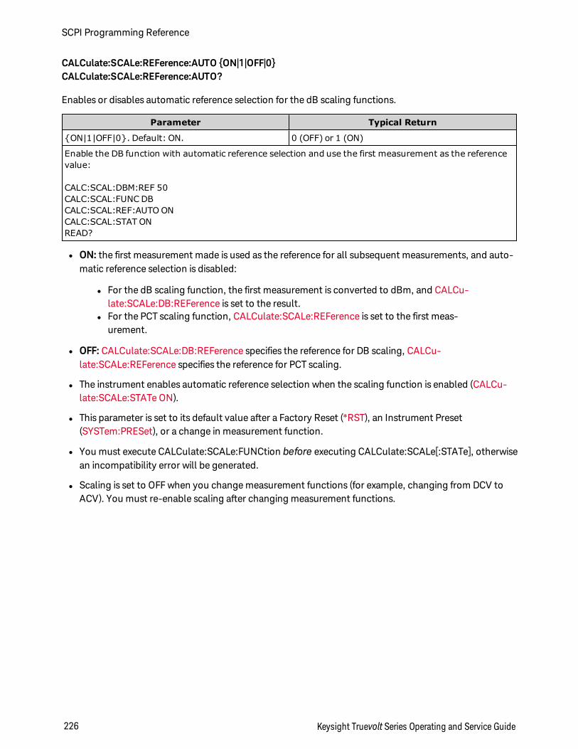
CALCulate:SCALe:REFerence:AUTO ON|1|OFF|0CALCulate:SCALe:REFerence:AUTO?
Enables or disables automatic reference selection for the dB scaling functions.
Parameter Typical Return
ON|1|OFF|0. Default: ON. 0 (OFF) or 1 (ON)
Enable the DB function with automatic reference selection and use the first measurement as the referencevalue:
CALC:SCAL:DBM:REF 50CALC:SCAL:FUNC DBCALC:SCAL:REF:AUTO ONCALC:SCAL:STAT ONREAD?
l ON: the first measurement made is used as the reference for all subsequent measurements, and auto-matic reference selection is disabled:
l For the dB scaling function, the first measurement is converted to dBm, and CALCu-late:SCALe:DB:REFerence is set to the result.
l For the PCT scaling function, CALCulate:SCALe:REFerence is set to the first meas-urement.
l OFF: CALCulate:SCALe:DB:REFerence specifies the reference for DB scaling, CALCu-late:SCALe:REFerence specifies the reference for PCT scaling.
l The instrument enables automatic reference selection when the scaling function is enabled (CALCu-late:SCALe:STATe ON).
l This parameter is set to its default value after a Factory Reset (*RST), an Instrument Preset(SYSTem:PRESet), or a change in measurement function.
l You must execute CALCulate:SCALe:FUNCtion before executing CALCulate:SCALe[:STATe], otherwisean incompatibility error will be generated.
l Scaling is set to OFF when you change measurement functions (for example, changing from DCV toACV). You must re-enable scaling after changing measurement functions.
SCPI Programming Reference
226 Keysight Truevolt Series Operating and Service Guide
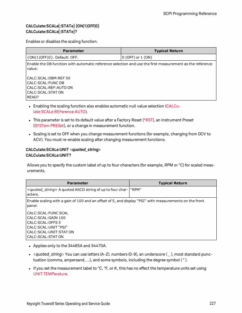
CALCulate:SCALe[:STATe] ON|1|OFF|0CALCulate:SCALe[:STATe]?
Enables or disables the scaling function.
Parameter Typical Return
ON|1|OFF|0. Default: OFF. 0 (OFF) or 1 (ON)
Enable the DB function with automatic reference selection and use the first measurement as the referencevalue:
CALC:SCAL:DBM:REF 50CALC:SCAL:FUNC DBCALC:SCAL:REF:AUTO ONCALC:SCAL:STAT ONREAD?
l Enabling the scaling function also enables automatic null value selection (CALCu-late:SCALe:REFerence:AUTO).
l This parameter is set to its default value after a Factory Reset (*RST), an Instrument Preset(SYSTem:PRESet), or a change in measurement function.
l Scaling is set to OFF when you change measurement functions (for example, changing from DCV toACV). You must re-enable scaling after changing measurement functions.
CALCulate:SCALe:UNIT <quoted_string>CALCulate:SCALe:UNIT?
Allows you to specify the custom label of up to four characters (for example, RPM or °C) for scaled meas-urements.
Parameter Typical Return
<quoted_string> A quoted ASCII string of up to four char-acters.
"RPM"
Enable scaling with a gain of 100 and an offset of 5, and display "PSI" with measurements on the frontpanel.
CALC:SCAL:FUNC SCALCALC:SCAL:GAIN 100CALC:SCAL:OFFS 5CALC:SCAL:UNIT "PSI"CALC:SCAL:UNIT:STAT ONCALC:SCAL:STAT ON
l Applies only to the 34465A and 34470A.
l <quoted_string> You can use letters (A-Z), numbers (0-9), an underscore ( _ ), most standard punc-tuation (comma, ampersand, …), and some symbols, including the degree symbol ( ° ).
l If you set the measurement label to °C, °F, or K, this has no effect the temperature units set usingUNIT:TEMPerature.
Keysight Truevolt Series Operating and Service Guide 227
SCPI Programming Reference
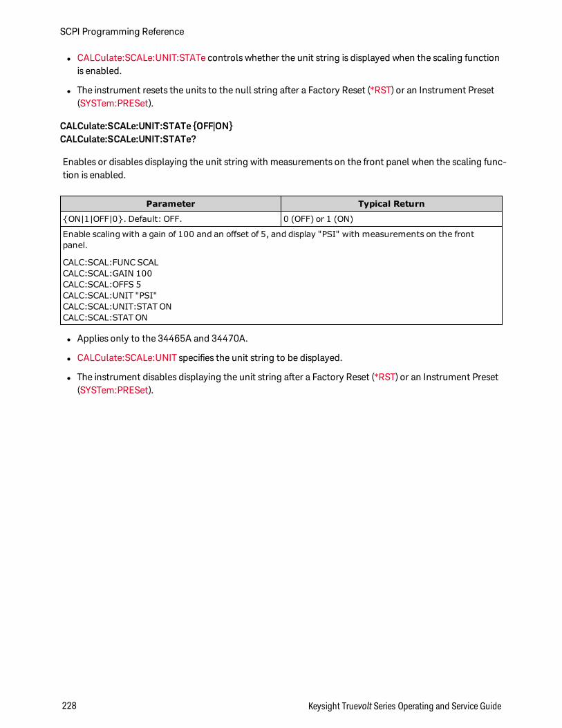
l CALCulate:SCALe:UNIT:STATe controls whether the unit string is displayed when the scaling functionis enabled.
l The instrument resets the units to the null string after a Factory Reset (*RST) or an Instrument Preset(SYSTem:PRESet).
CALCulate:SCALe:UNIT:STATe OFF|ONCALCulate:SCALe:UNIT:STATe?
Enables or disables displaying the unit string with measurements on the front panel when the scaling func-tion is enabled.
Parameter Typical Return
ON|1|OFF|0. Default: OFF. 0 (OFF) or 1 (ON)
Enable scaling with a gain of 100 and an offset of 5, and display "PSI" with measurements on the frontpanel.
CALC:SCAL:FUNC SCALCALC:SCAL:GAIN 100CALC:SCAL:OFFS 5CALC:SCAL:UNIT "PSI"CALC:SCAL:UNIT:STAT ONCALC:SCAL:STAT ON
l Applies only to the 34465A and 34470A.
l CALCulate:SCALe:UNIT specifies the unit string to be displayed.
l The instrument disables displaying the unit string after a Factory Reset (*RST) or an Instrument Preset(SYSTem:PRESet).
SCPI Programming Reference
228 Keysight Truevolt Series Operating and Service Guide
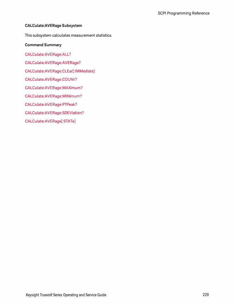
CALCulate:AVERage Subsystem
This subsystem calculates measurement statistics.
Command Summary
CALCulate:AVERage:ALL?
CALCulate:AVERage:AVERage?
CALCulate:AVERage:CLEar[:IMMediate]
CALCulate:AVERage:COUNt?
CALCulate:AVERage:MAXimum?
CALCulate:AVERage:MINimum?
CALCulate:AVERage:PTPeak?
CALCulate:AVERage:SDEViation?
CALCulate:AVERage[:STATe]
Keysight Truevolt Series Operating and Service Guide 229
SCPI Programming Reference
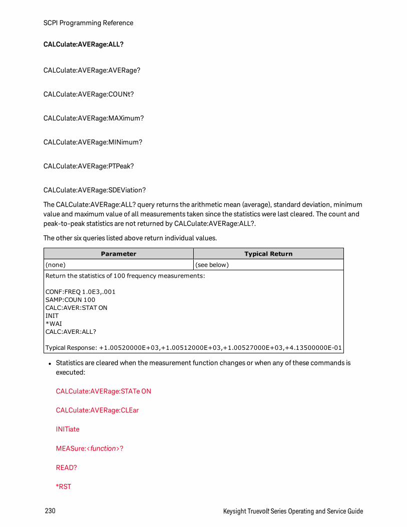
CALCulate:AVERage:ALL?
CALCulate:AVERage:AVERage?
CALCulate:AVERage:COUNt?
CALCulate:AVERage:MAXimum?
CALCulate:AVERage:MINimum?
CALCulate:AVERage:PTPeak?
CALCulate:AVERage:SDEViation?
The CALCulate:AVERage:ALL? query returns the arithmetic mean (average), standard deviation, minimumvalue and maximum value of all measurements taken since the statistics were last cleared. The count andpeak-to-peak statistics are not returned by CALCulate:AVERage:ALL?.
The other six queries listed above return individual values.
Parameter Typical Return
(none) (see below)
Return the statistics of 100 frequency measurements:
CONF:FREQ 1.0E3,.001SAMP:COUN 100CALC:AVER:STAT ONINIT*WAICALC:AVER:ALL?
Typical Response: +1.00520000E+03,+1.00512000E+03,+1.00527000E+03,+4.13500000E-01
l Statistics are cleared when the measurement function changes or when any of these commands isexecuted:
CALCulate:AVERage:STATe ON
CALCulate:AVERage:CLEar
INITiate
MEASure:<function>?
READ?
*RST
SCPI Programming Reference
230 Keysight Truevolt Series Operating and Service Guide

SYSTem:PRESet
l All values are returned in the form +1.23450000E+01.
l When dB or dBm scaling is used, the CALC:AVER:AVER and CALC:AVER:SDEV queries return+9.91000000E+37 (not a number).
Keysight Truevolt Series Operating and Service Guide 231
SCPI Programming Reference
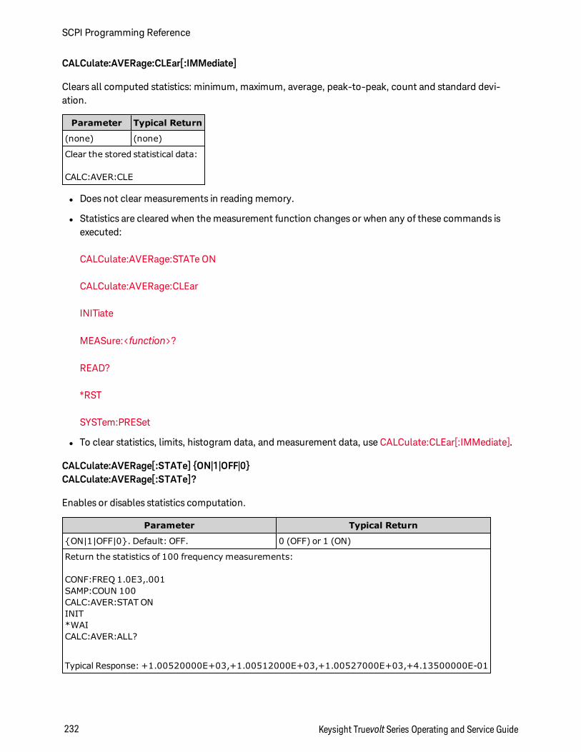
CALCulate:AVERage:CLEar[:IMMediate]
Clears all computed statistics: minimum, maximum, average, peak-to-peak, count and standard devi-ation.
Parameter Typical Return
(none) (none)
Clear the stored statistical data:
CALC:AVER:CLE
l Does not clear measurements in reading memory.
l Statistics are cleared when the measurement function changes or when any of these commands isexecuted:
CALCulate:AVERage:STATe ON
CALCulate:AVERage:CLEar
INITiate
MEASure:<function>?
READ?
*RST
SYSTem:PRESet
l To clear statistics, limits, histogram data, and measurement data, use CALCulate:CLEar[:IMMediate].
CALCulate:AVERage[:STATe] ON|1|OFF|0CALCulate:AVERage[:STATe]?
Enables or disables statistics computation.
Parameter Typical Return
ON|1|OFF|0. Default: OFF. 0 (OFF) or 1 (ON)
Return the statistics of 100 frequency measurements:
CONF:FREQ 1.0E3,.001SAMP:COUN 100CALC:AVER:STAT ONINIT*WAICALC:AVER:ALL?
Typical Response: +1.00520000E+03,+1.00512000E+03,+1.00527000E+03,+4.13500000E-01
SCPI Programming Reference
232 Keysight Truevolt Series Operating and Service Guide
l Statistics are cleared when the measurement function changes or when any of these commands isexecuted:
CALCulate:AVERage:STATe ON
CALCulate:AVERage:CLEar
INITiate
MEASure:<function>?
READ?
*RST
SYSTem:PRESet
l The instrument turns this setting OFF when the measurement function is changed or after *RST orSYSTem:PRESet.
Keysight Truevolt Series Operating and Service Guide 233
SCPI Programming Reference
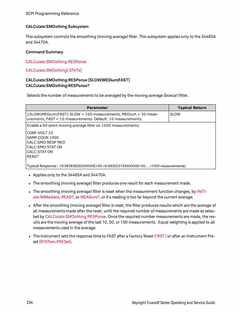
CALCulate:SMOothing Subsystem
This subsystem controls the smoothing (moving average) filter. This subsystem applies only to the 34465Aand 34470A.
Command Summary
CALCulate:SMOothing:RESPonse
CALCulate:SMOothing[:STATe]
CALCulate:SMOothing:RESPonse SLOW|MEDium|FASTCALCulate:SMOothing:RESPonse?
Selects the number of measurements to be averaged by the moving average (boxcar) filter.
Parameter Typical Return
SLOW|MEDium|FAST SLOW = 100 measurements, MEDium = 50 meas-urements, FAST = 10 measurements. Default: 10 measurements.
SLOW
Enable a 50-point moving average filter on 1000 measurements:
CONF:VOLT 10SAMP:COUN 1000CALC:SMO:RESP MEDCALC:SMO:STAT ONCALC:STAT ONREAD?
Typical Response: +9.99383828200000E+00,+9.99352315400000E+00,... (1000 measurements)
l Applies only to the 34465A and 34470A.
l The smoothing (moving average) filter produces one result for each measurement made.
l The smoothing (moving average) filter is reset when the measurement function changes, by INITi-ate:IMMediate, READ?, or MEASure?, or if a reading is too far beyond the current average.
l After the smoothing (moving average) filter is reset, the filter produces results which are the average ofall measurements made after the reset, until the required number of measurements are made as selec-ted by CALCulate:SMOothing:RESPonse. Once the required number measurements are made, the res-ults are the moving average of the last 10, 50, or 100 measurements. Equal weighting is applied to allmeasurements used in the average.
l The instrument sets the response time to FAST after a Factory Reset (*RST ) or after an Instrument Pre-set (SYSTem:PRESet).
SCPI Programming Reference
234 Keysight Truevolt Series Operating and Service Guide
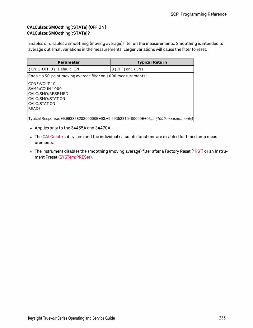
CALCulate:SMOothing[:STATe] OFF|ONCALCulate:SMOothing[:STATe]?
Enables or disables a smoothing (moving average) filter on the measurements. Smoothing is intended toaverage out small variations in the measurements. Larger variations will cause the filter to reset.
Parameter Typical Return
ON|1|OFF|0. Default: ON. 0 (OFF) or 1 (ON)
Enable a 50-point moving average filter on 1000 measurements:
CONF:VOLT 10SAMP:COUN 1000CALC:SMO:RESP MEDCALC:SMO:STAT ONCALC:STAT ONREAD?
Typical Response:+9.99383828200000E+03,+9.99352315400000E+03,... (1000 measurements)
l Applies only to the 34465A and 34470A.
l The CALCulate subsystem and the individual calculate functions are disabled for timestamp meas-urements.
l The instrument disables the smoothing (moving average) filter after a Factory Reset (*RST) or an Instru-ment Preset (SYSTem:PRESet).
Keysight Truevolt Series Operating and Service Guide 235
SCPI Programming Reference
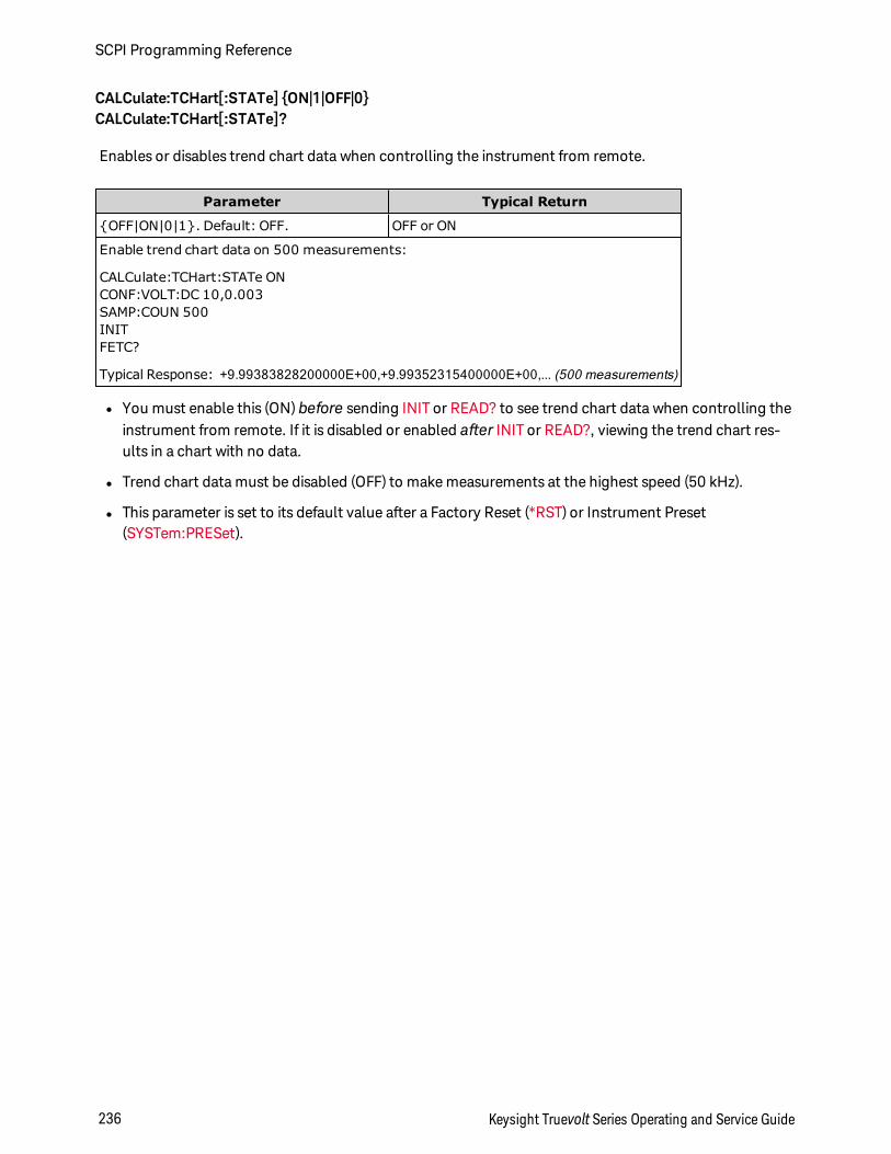
CALCulate:TCHart[:STATe] ON|1|OFF|0CALCulate:TCHart[:STATe]?
Enables or disables trend chart data when controlling the instrument from remote.
Parameter Typical Return
OFF|ON|0|1. Default: OFF. OFF or ON
Enable trend chart data on 500 measurements:
CALCulate:TCHart:STATe ONCONF:VOLT:DC 10,0.003SAMP:COUN 500INITFETC?
Typical Response: +9.99383828200000E+00,+9.99352315400000E+00,... (500 measurements)
l You must enable this (ON) before sending INIT or READ? to see trend chart data when controlling theinstrument from remote. If it is disabled or enabled after INIT or READ?, viewing the trend chart res-ults in a chart with no data.
l Trend chart data must be disabled (OFF) to make measurements at the highest speed (50 kHz).
l This parameter is set to its default value after a Factory Reset (*RST) or Instrument Preset(SYSTem:PRESet).
SCPI Programming Reference
236 Keysight Truevolt Series Operating and Service Guide
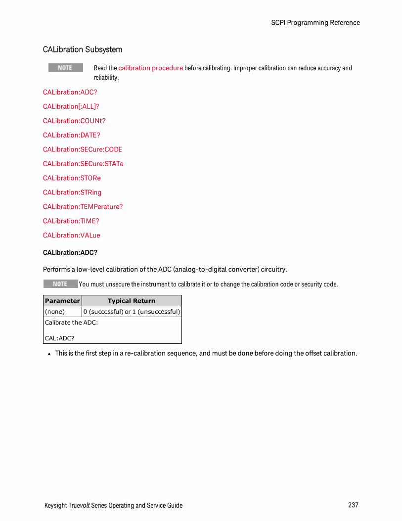
CALibration Subsystem
Read the calibration procedure before calibrating. Improper calibration can reduce accuracy andreliability.
CALibration:ADC?
CALibration[:ALL]?
CALibration:COUNt?
CALibration:DATE?
CALibration:SECure:CODE
CALibration:SECure:STATe
CALibration:STORe
CALibration:STRing
CALibration:TEMPerature?
CALibration:TIME?
CALibration:VALue
CALibration:ADC?
Performs a low-level calibration of the ADC (analog-to-digital converter) circuitry.
You must unsecure the instrument to calibrate it or to change the calibration code or security code.
Parameter Typical Return
(none) 0 (successful) or 1 (unsuccessful)
Calibrate the ADC:
CAL:ADC?
l This is the first step in a re-calibration sequence, and must be done before doing the offset calibration.
Keysight Truevolt Series Operating and Service Guide 237
SCPI Programming Reference
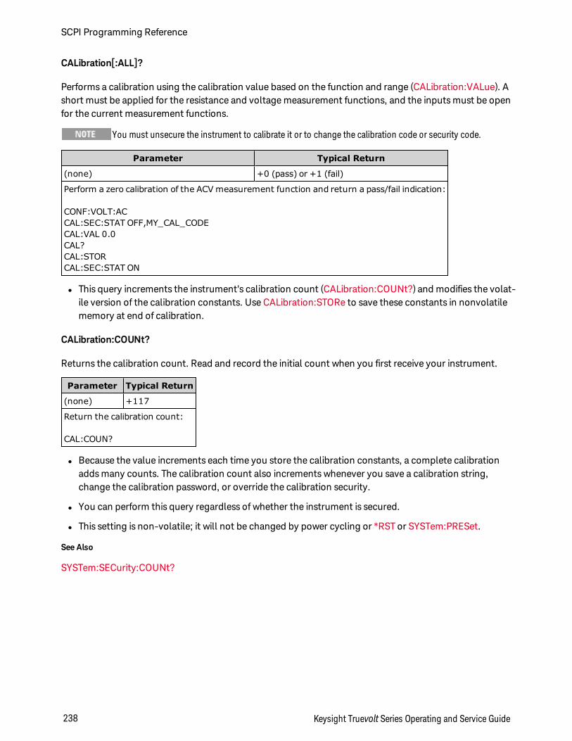
CALibration[:ALL]?
Performs a calibration using the calibration value based on the function and range (CALibration:VALue). Ashort must be applied for the resistance and voltage measurement functions, and the inputs must be openfor the current measurement functions.
You must unsecure the instrument to calibrate it or to change the calibration code or security code.
Parameter Typical Return
(none) +0 (pass) or +1 (fail)
Perform a zero calibration of the ACV measurement function and return a pass/fail indication:
CONF:VOLT:ACCAL:SEC:STAT OFF,MY_CAL_CODECAL:VAL 0.0CAL?CAL:STORCAL:SEC:STAT ON
l This query increments the instrument’s calibration count (CALibration:COUNt?) and modifies the volat-ile version of the calibration constants. Use CALibration:STORe to save these constants in nonvolatilememory at end of calibration.
CALibration:COUNt?
Returns the calibration count. Read and record the initial count when you first receive your instrument.
Parameter Typical Return
(none) +117
Return the calibration count:
CAL:COUN?
l Because the value increments each time you store the calibration constants, a complete calibrationadds many counts. The calibration count also increments whenever you save a calibration string,change the calibration password, or override the calibration security.
l You can perform this query regardless of whether the instrument is secured.
l This setting is non-volatile; it will not be changed by power cycling or *RST or SYSTem:PRESet.
See Also
SYSTem:SECurity:COUNt?
SCPI Programming Reference
238 Keysight Truevolt Series Operating and Service Guide
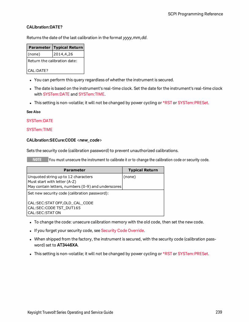
CALibration:DATE?
Returns the date of the last calibration in the format yyyy,mm,dd.
Parameter Typical Return
(none) 2014,4,26
Return the calibration date:
CAL:DATE?
l You can perform this query regardless of whether the instrument is secured.
l The date is based on the instrument's real-time clock. Set the date for the instrument's real-time clockwith SYSTem:DATE and SYSTem:TIME.
l This setting is non-volatile; it will not be changed by power cycling or *RST or SYSTem:PRESet.
See Also
SYSTem:DATE
SYSTem:TIME
CALibration:SECure:CODE <new_code>
Sets the security code (calibration password) to prevent unauthorized calibrations.
You must unsecure the instrument to calibrate it or to change the calibration code or security code.
Parameter Typical Return
Unquoted string up to 12 charactersMust start with letter (A-Z)May contain letters, numbers (0-9) and underscores
(none)
Set new security code (calibration password):
CAL:SEC:STAT OFF,OLD_CAL_CODECAL:SEC:CODE TST_DUT165CAL:SEC:STAT ON
l To change the code: unsecure calibration memory with the old code, then set the new code.
l If you forget your security code, see Security Code Override.
l When shipped from the factory, the instrument is secured, with the security code (calibration pass-word) set to AT3446XA.
l This setting is non-volatile; it will not be changed by power cycling or *RST or SYSTem:PRESet.
Keysight Truevolt Series Operating and Service Guide 239
SCPI Programming Reference
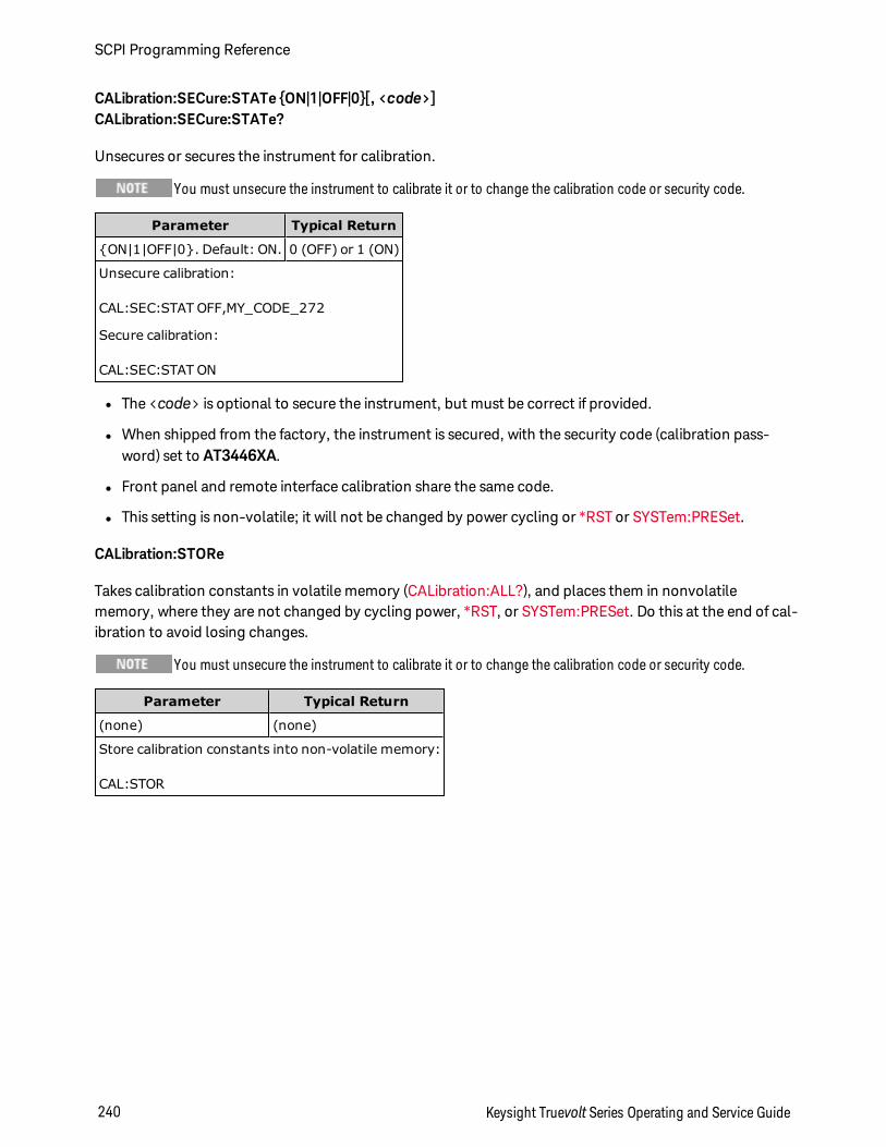
CALibration:SECure:STATe ON|1|OFF|0[, <code>]CALibration:SECure:STATe?
Unsecures or secures the instrument for calibration.
You must unsecure the instrument to calibrate it or to change the calibration code or security code.
Parameter Typical Return
ON|1|OFF|0. Default: ON. 0 (OFF) or 1 (ON)
Unsecure calibration:
CAL:SEC:STAT OFF,MY_CODE_272
Secure calibration:
CAL:SEC:STAT ON
l The <code> is optional to secure the instrument, but must be correct if provided.
l When shipped from the factory, the instrument is secured, with the security code (calibration pass-word) set to AT3446XA.
l Front panel and remote interface calibration share the same code.
l This setting is non-volatile; it will not be changed by power cycling or *RST or SYSTem:PRESet.
CALibration:STORe
Takes calibration constants in volatile memory (CALibration:ALL?), and places them in nonvolatilememory, where they are not changed by cycling power, *RST, or SYSTem:PRESet. Do this at the end of cal-ibration to avoid losing changes.
You must unsecure the instrument to calibrate it or to change the calibration code or security code.
Parameter Typical Return
(none) (none)
Store calibration constants into non-volatile memory:
CAL:STOR
SCPI Programming Reference
240 Keysight Truevolt Series Operating and Service Guide
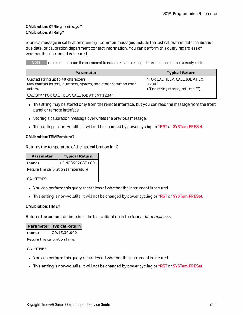
CALibration:STRing "<string>"CALibration:STRing?
Stores a message in calibration memory. Common messages include the last calibration date, calibrationdue date, or calibration department contact information. You can perform this query regardless ofwhether the instrument is secured.
You must unsecure the instrument to calibrate it or to change the calibration code or security code.
Parameter Typical Return
Quoted string up to 40 charactersMay contain letters, numbers, spaces, and other common char-acters.
"FOR CAL HELP, CALL JOE AT EXT1234"(If no string stored, returns "")
CAL:STR "FOR CAL HELP, CALL JOE AT EXT 1234"
l This string may be stored only from the remote interface, but you can read the message from the frontpanel or remote interface.
l Storing a calibration message overwrites the previous message.
l This setting is non-volatile; it will not be changed by power cycling or *RST or SYSTem:PRESet.
CALibration:TEMPerature?
Returns the temperature of the last calibration in °C.
Parameter Typical Return
(none) +2.42850208E+001
Return the calibration temperature:
CAL:TEMP?
l You can perform this query regardless of whether the instrument is secured.
l This setting is non-volatile; it will not be changed by power cycling or *RST or SYSTem:PRESet.
CALibration:TIME?
Returns the amount of time since the last calibration in the format hh,mm,ss.sss.
Parameter Typical Return
(none) 20,15,30.000
Return the calibration time:
CAL:TIME?
l You can perform this query regardless of whether the instrument is secured.
l This setting is non-volatile; it will not be changed by power cycling or *RST or SYSTem:PRESet.
Keysight Truevolt Series Operating and Service Guide 241
SCPI Programming Reference
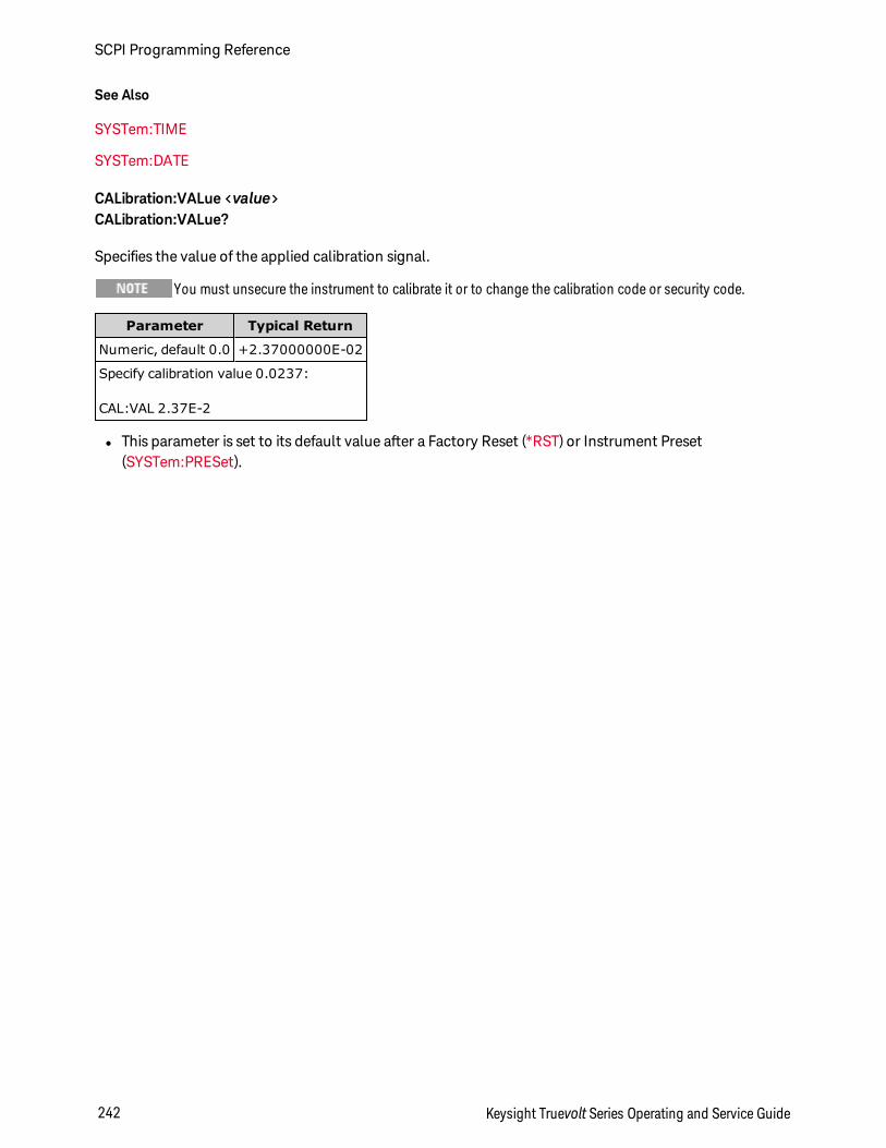
See Also
SYSTem:TIME
SYSTem:DATE
CALibration:VALue <value>CALibration:VALue?
Specifies the value of the applied calibration signal.
You must unsecure the instrument to calibrate it or to change the calibration code or security code.
Parameter Typical Return
Numeric, default 0.0 +2.37000000E-02
Specify calibration value 0.0237:
CAL:VAL 2.37E-2
l This parameter is set to its default value after a Factory Reset (*RST) or Instrument Preset(SYSTem:PRESet).
SCPI Programming Reference
242 Keysight Truevolt Series Operating and Service Guide
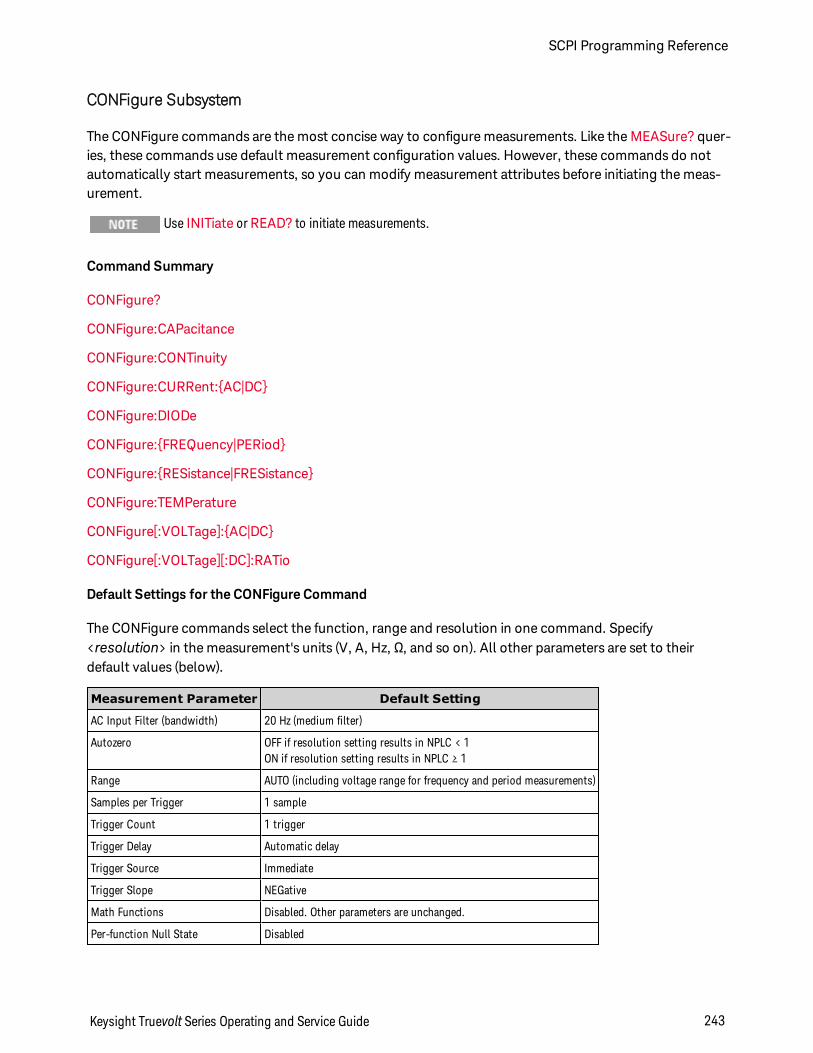
CONFigure Subsystem
The CONFigure commands are the most concise way to configure measurements. Like the MEASure? quer-ies, these commands use default measurement configuration values. However, these commands do notautomatically start measurements, so you can modify measurement attributes before initiating the meas-urement.
Use INITiate or READ? to initiate measurements.
Command Summary
CONFigure?
CONFigure:CAPacitance
CONFigure:CONTinuity
CONFigure:CURRent:AC|DC
CONFigure:DIODe
CONFigure:FREQuency|PERiod
CONFigure:RESistance|FRESistance
CONFigure:TEMPerature
CONFigure[:VOLTage]:AC|DC
CONFigure[:VOLTage][:DC]:RATio
Default Settings for the CONFigure Command
The CONFigure commands select the function, range and resolution in one command. Specify<resolution> in the measurement's units (V, A, Hz, Ω, and so on). All other parameters are set to theirdefault values (below).
Measurement Parameter Default Setting
AC Input Filter (bandwidth) 20 Hz (medium filter)
Autozero OFF if resolution setting results in NPLC < 1ON if resolution setting results in NPLC ≥ 1
Range AUTO (including voltage range for frequency and period measurements)
Samples per Trigger 1 sample
Trigger Count 1 trigger
Trigger Delay Automatic delay
Trigger Source Immediate
Trigger Slope NEGative
Math Functions Disabled. Other parameters are unchanged.
Per-function Null State Disabled
Keysight Truevolt Series Operating and Service Guide 243
SCPI Programming Reference
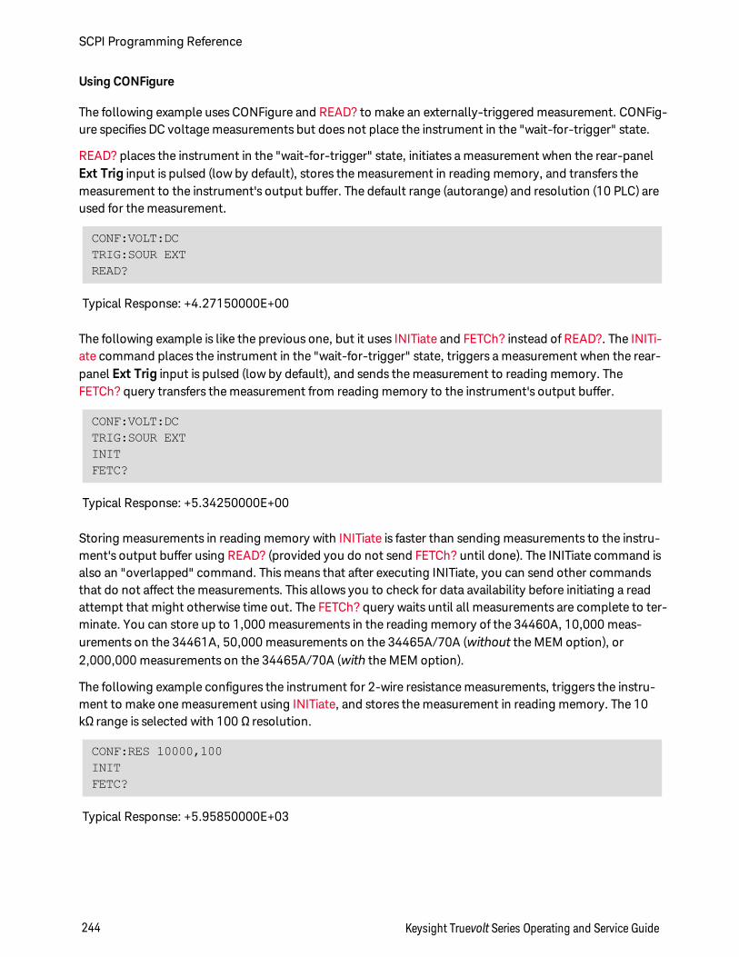
Using CONFigure
The following example uses CONFigure and READ? to make an externally-triggered measurement. CONFig-ure specifies DC voltage measurements but does not place the instrument in the "wait-for-trigger" state.
READ? places the instrument in the "wait-for-trigger" state, initiates a measurement when the rear-panelExt Trig input is pulsed (low by default), stores the measurement in reading memory, and transfers themeasurement to the instrument's output buffer. The default range (autorange) and resolution (10 PLC) areused for the measurement.
CONF:VOLT:DCTRIG:SOUR EXTREAD?
Typical Response: +4.27150000E+00
The following example is like the previous one, but it uses INITiate and FETCh? instead of READ?. The INITi-ate command places the instrument in the "wait-for-trigger" state, triggers a measurement when the rear-panel Ext Trig input is pulsed (low by default), and sends the measurement to reading memory. TheFETCh? query transfers the measurement from reading memory to the instrument's output buffer.
CONF:VOLT:DCTRIG:SOUR EXTINITFETC?
Typical Response: +5.34250000E+00
Storing measurements in reading memory with INITiate is faster than sending measurements to the instru-ment's output buffer using READ? (provided you do not send FETCh? until done). The INITiate command isalso an "overlapped" command. This means that after executing INITiate, you can send other commandsthat do not affect the measurements. This allows you to check for data availability before initiating a readattempt that might otherwise time out. The FETCh? query waits until all measurements are complete to ter-minate. You can store up to 1,000 measurements in the reading memory of the 34460A, 10,000 meas-urements on the 34461A, 50,000 measurements on the 34465A/70A (without the MEM option), or2,000,000 measurements on the 34465A/70A (with the MEM option).
The following example configures the instrument for 2-wire resistance measurements, triggers the instru-ment to make one measurement using INITiate, and stores the measurement in reading memory. The 10kΩ range is selected with 100 Ω resolution.
CONF:RES 10000,100INITFETC?
Typical Response: +5.95850000E+03
SCPI Programming Reference
244 Keysight Truevolt Series Operating and Service Guide
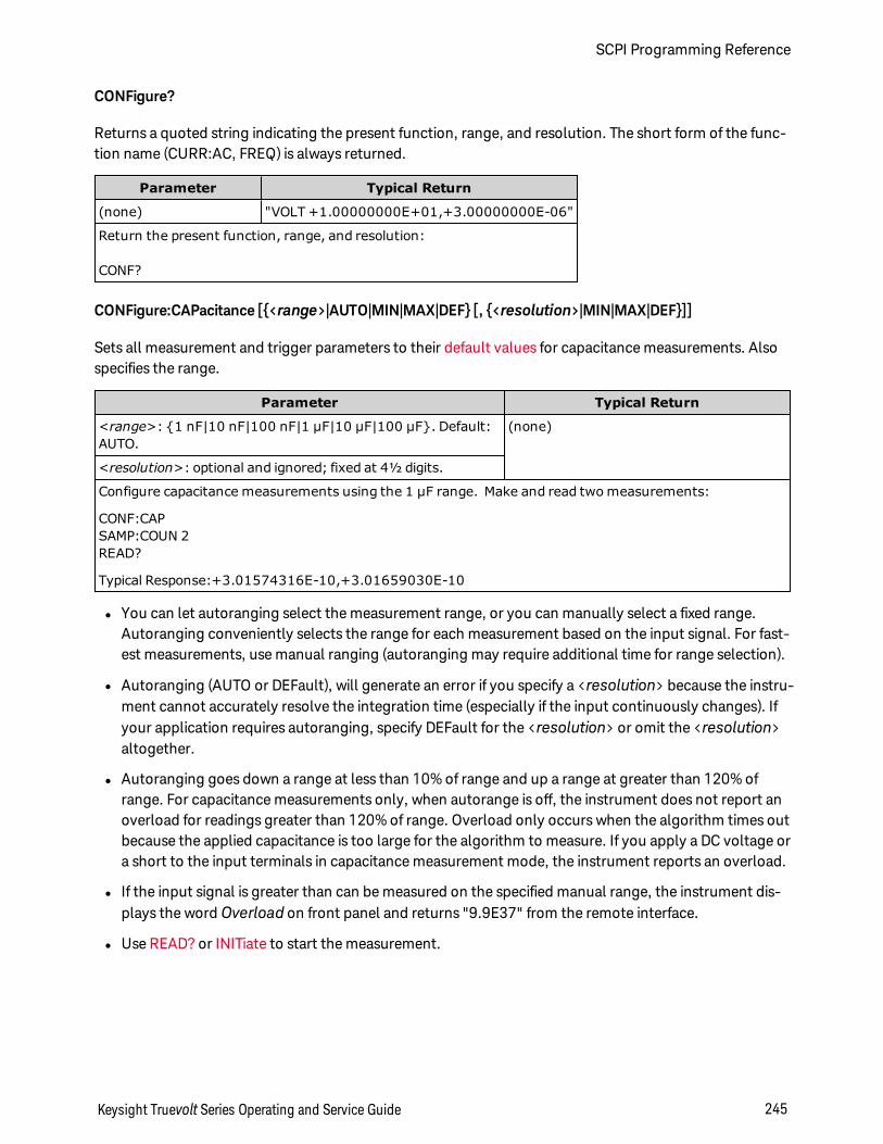
CONFigure?
Returns a quoted string indicating the present function, range, and resolution. The short form of the func-tion name (CURR:AC, FREQ) is always returned.
Parameter Typical Return
(none) "VOLT +1.00000000E+01,+3.00000000E-06"
Return the present function, range, and resolution:
CONF?
CONFigure:CAPacitance [<range>|AUTO|MIN|MAX|DEF [, <resolution>|MIN|MAX|DEF]]
Sets all measurement and trigger parameters to their default values for capacitance measurements. Alsospecifies the range.
Parameter Typical Return
<range>: 1 nF|10 nF|100 nF|1 µF|10 µF|100 µF. Default:AUTO.
(none)
<resolution>: optional and ignored; fixed at 4½ digits.
Configure capacitance measurements using the 1 µF range. Make and read two measurements:
CONF:CAPSAMP:COUN 2READ?
Typical Response:+3.01574316E-10,+3.01659030E-10
l You can let autoranging select the measurement range, or you can manually select a fixed range.Autoranging conveniently selects the range for each measurement based on the input signal. For fast-est measurements, use manual ranging (autoranging may require additional time for range selection).
l Autoranging (AUTO or DEFault), will generate an error if you specify a <resolution> because the instru-ment cannot accurately resolve the integration time (especially if the input continuously changes). Ifyour application requires autoranging, specify DEFault for the <resolution> or omit the <resolution>altogether.
l Autoranging goes down a range at less than 10% of range and up a range at greater than 120% ofrange. For capacitance measurements only, when autorange is off, the instrument does not report anoverload for readings greater than 120% of range. Overload only occurs when the algorithm times outbecause the applied capacitance is too large for the algorithm to measure. If you apply a DC voltage ora short to the input terminals in capacitance measurement mode, the instrument reports an overload.
l If the input signal is greater than can be measured on the specified manual range, the instrument dis-plays the word Overload on front panel and returns "9.9E37" from the remote interface.
l Use READ? or INITiate to start the measurement.
Keysight Truevolt Series Operating and Service Guide 245
SCPI Programming Reference
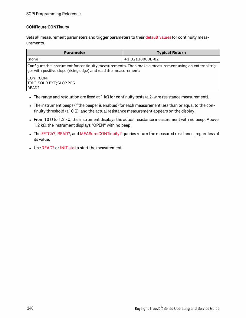
CONFigure:CONTinuity
Sets all measurement parameters and trigger parameters to their default values for continuity meas-urements.
Parameter Typical Return
(none) +1.32130000E-02
Configure the instrument for continuity measurements. Then make a measurement using an external trig-ger with positive slope (rising edge) and read the measurement:
CONF:CONTTRIG:SOUR EXT;SLOP POSREAD?
l The range and resolution are fixed at 1 kΩ for continuity tests (a 2-wire resistance measurement).
l The instrument beeps (if the beeper is enabled) for each measurement less than or equal to the con-tinuity threshold (≤10 Ω), and the actual resistance measurement appears on the display.
l From 10 Ω to 1.2 kΩ, the instrument displays the actual resistance measurement with no beep. Above1.2 kΩ, the instrument displays "OPEN" with no beep.
l The FETCh?, READ?, and MEASure:CONTinuity? queries return the measured resistance, regardless ofits value.
l Use READ? or INITiate to start the measurement.
SCPI Programming Reference
246 Keysight Truevolt Series Operating and Service Guide
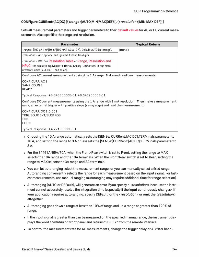
CONFigure:CURRent:AC|DC [<range>|AUTO|MIN|MAX|DEF [, <resolution>|MIN|MAX|DEF]]
Sets all measurement parameters and trigger parameters to their default values for AC or DC current meas-urements. Also specifies the range and resolution.
Parameter Typical Return
<range>: 100 µA|1 mA|10 mA|100 mA|1 A|3 A|10 A. Default: AUTO (autorange). (none)
<resolution> (AC): optional and ignored; fixed at 6½ digits.
<resolution> (DC): See Resolution Table or Range, Resolution andNPLC. The default is equivalent to 10 PLC. Specify <resolution> in the meas-urement's units (V, A, Hz, Ω, and so on).
Configure AC current measurements using the 1 A range. Make and read two measurements:
CONF:CURR:AC 1SAMP:COUN 2READ?
Typical Response: +8.54530000E-01,+8.54520000E-01
Configure DC current measurements using the 1 A range with 1 mA resolution. Then make a measurementusing an external trigger with positive slope (rising edge) and read the measurement:
CONF:CURR:DC 1,0.001TRIG:SOUR EXT;SLOP POSINITFETC?
Typical Response: +4.27150000E-01
l Choosing the 10 A range automatically sets the [SENSe:]CURRent:AC|DC:TERMinals parameter to10 A, and setting the range to 3 A or less sets the [SENSe:]CURRent:AC|DC:TERMinals parameter to3 A.
l For the 34461A/65A/70A, when the Front/Rear switch is set to Front, setting the range to MAXselects the 10A range and the 10A terminals. When the Front/Rear switch is set to Rear, setting therange to MAX selects the 3A range and 3A terminals.
l You can let autoranging select the measurement range, or you can manually select a fixed range.Autoranging conveniently selects the range for each measurement based on the input signal. For fast-est measurements, use manual ranging (autoranging may require additional time for range selection).
l Autoranging (AUTO or DEFault), will generate an error if you specify a <resolution> because the instru-ment cannot accurately resolve the integration time (especially if the input continuously changes). Ifyour application requires autoranging, specify DEFault for the <resolution> or omit the <resolution>altogether.
l Autoranging goes down a range at less than 10% of range and up a range at greater than 120% ofrange.
l If the input signal is greater than can be measured on the specified manual range, the instrument dis-plays the word Overload on front panel and returns "9.9E37" from the remote interface.
l To control the measurement rate for AC measurements, change the trigger delay or AC filter band-
Keysight Truevolt Series Operating and Service Guide 247
SCPI Programming Reference
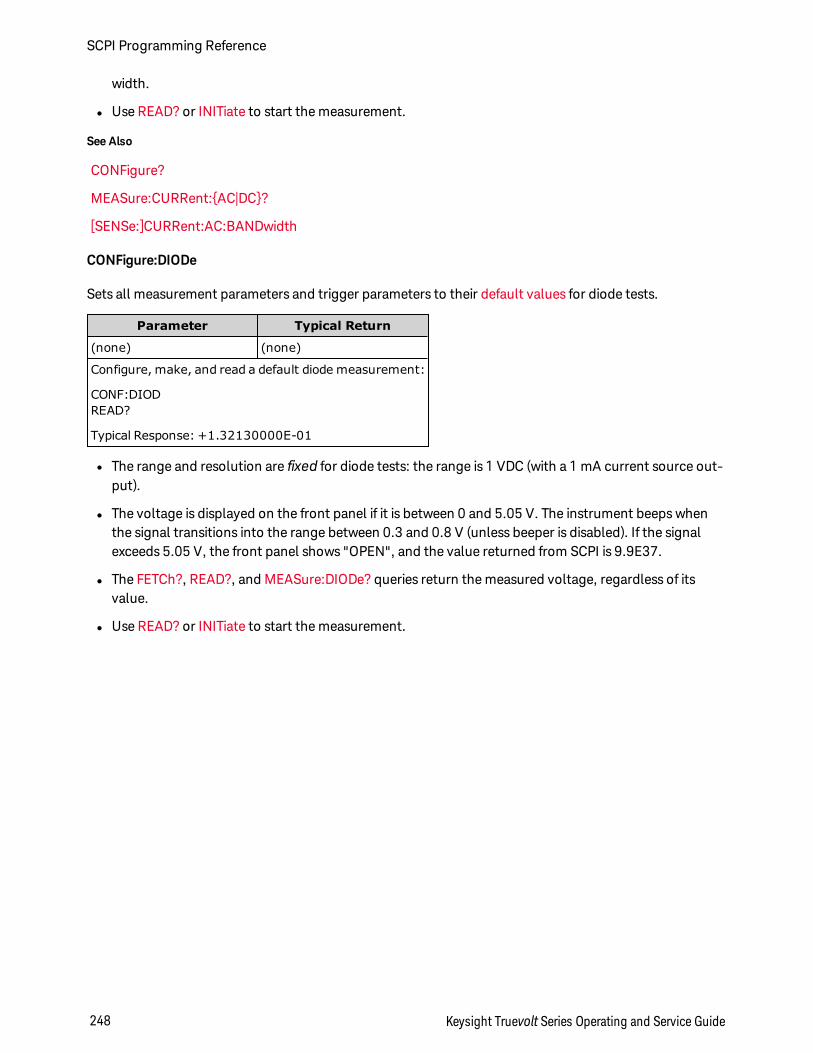
width.
l Use READ? or INITiate to start the measurement.
See Also
CONFigure?
MEASure:CURRent:AC|DC?
[SENSe:]CURRent:AC:BANDwidth
CONFigure:DIODe
Sets all measurement parameters and trigger parameters to their default values for diode tests.
Parameter Typical Return
(none) (none)
Configure, make, and read a default diode measurement:
CONF:DIODREAD?
Typical Response: +1.32130000E-01
l The range and resolution are fixed for diode tests: the range is 1 VDC (with a 1 mA current source out-put).
l The voltage is displayed on the front panel if it is between 0 and 5.05 V. The instrument beeps whenthe signal transitions into the range between 0.3 and 0.8 V (unless beeper is disabled). If the signalexceeds 5.05 V, the front panel shows "OPEN", and the value returned from SCPI is 9.9E37.
l The FETCh?, READ?, and MEASure:DIODe? queries return the measured voltage, regardless of itsvalue.
l Use READ? or INITiate to start the measurement.
SCPI Programming Reference
248 Keysight Truevolt Series Operating and Service Guide
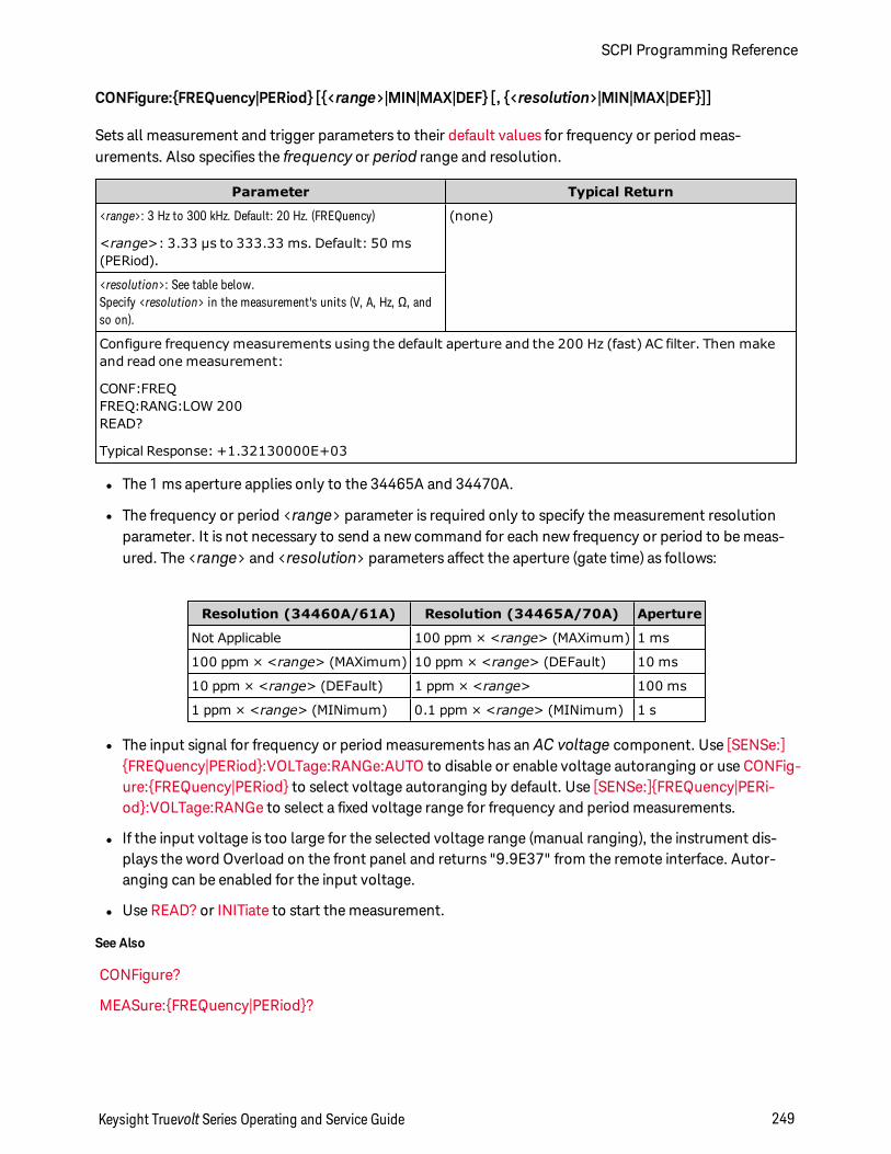
CONFigure:FREQuency|PERiod [<range>|MIN|MAX|DEF [, <resolution>|MIN|MAX|DEF]]
Sets all measurement and trigger parameters to their default values for frequency or period meas-urements. Also specifies the frequency or period range and resolution.
Parameter Typical Return
<range>: 3 Hz to 300 kHz. Default: 20 Hz. (FREQuency)
<range>: 3.33 µs to 333.33 ms. Default: 50 ms(PERiod).
(none)
<resolution>: See table below.Specify <resolution> in the measurement's units (V, A, Hz, Ω, andso on).
Configure frequency measurements using the default aperture and the 200 Hz (fast) AC filter. Then makeand read one measurement:
CONF:FREQFREQ:RANG:LOW 200READ?
Typical Response: +1.32130000E+03
l The 1 ms aperture applies only to the 34465A and 34470A.
l The frequency or period <range> parameter is required only to specify the measurement resolutionparameter. It is not necessary to send a new command for each new frequency or period to be meas-ured. The <range> and <resolution> parameters affect the aperture (gate time) as follows:
Resolution (34460A/61A) Resolution (34465A/70A) Aperture
Not Applicable 100 ppm × <range> (MAXimum) 1 ms
100 ppm × <range> (MAXimum) 10 ppm × <range> (DEFault) 10 ms
10 ppm × <range> (DEFault) 1 ppm × <range> 100 ms
1 ppm × <range> (MINimum) 0.1 ppm × <range> (MINimum) 1 s
l The input signal for frequency or period measurements has an AC voltage component. Use [SENSe:]FREQuency|PERiod:VOLTage:RANGe:AUTO to disable or enable voltage autoranging or use CONFig-ure:FREQuency|PERiod to select voltage autoranging by default. Use [SENSe:]FREQuency|PERi-od:VOLTage:RANGe to select a fixed voltage range for frequency and period measurements.
l If the input voltage is too large for the selected voltage range (manual ranging), the instrument dis-plays the word Overload on the front panel and returns "9.9E37" from the remote interface. Autor-anging can be enabled for the input voltage.
l Use READ? or INITiate to start the measurement.
See Also
CONFigure?
MEASure:FREQuency|PERiod?
Keysight Truevolt Series Operating and Service Guide 249
SCPI Programming Reference
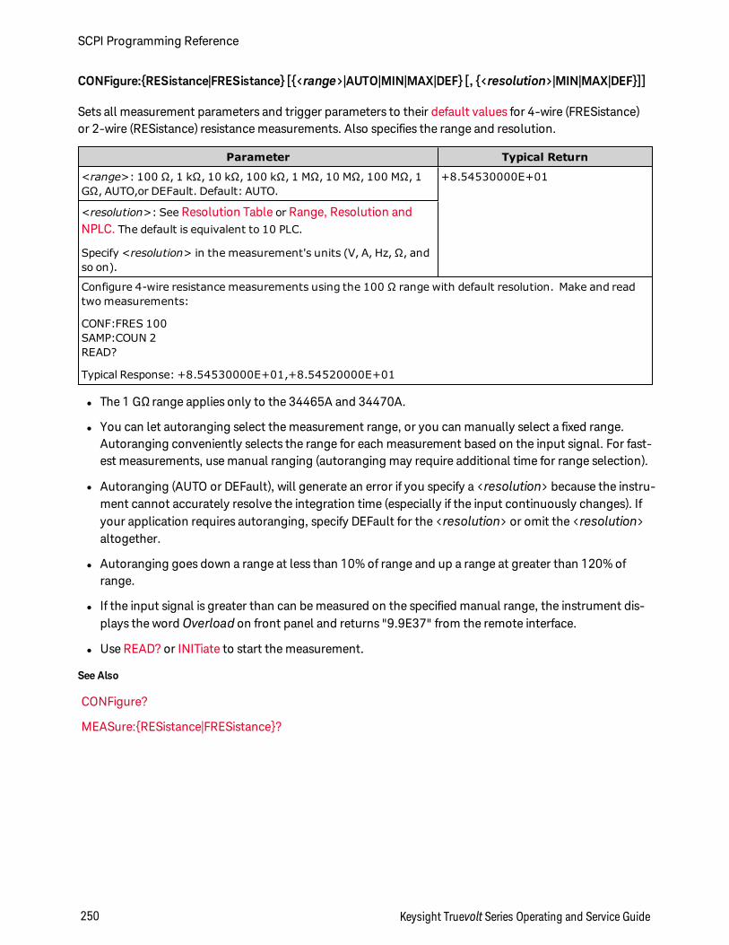
CONFigure:RESistance|FRESistance [<range>|AUTO|MIN|MAX|DEF [, <resolution>|MIN|MAX|DEF]]
Sets all measurement parameters and trigger parameters to their default values for 4-wire (FRESistance)or 2-wire (RESistance) resistance measurements. Also specifies the range and resolution.
Parameter Typical Return
<range>: 100 Ω, 1 kΩ, 10 kΩ, 100 kΩ, 1 MΩ, 10 MΩ, 100 MΩ, 1GΩ, AUTO,or DEFault. Default: AUTO.
+8.54530000E+01
<resolution>: See Resolution Table or Range, Resolution andNPLC. The default is equivalent to 10 PLC.
Specify <resolution> in the measurement's units (V, A, Hz, Ω, andso on).
Configure 4-wire resistance measurements using the 100 Ω range with default resolution. Make and readtwo measurements:
CONF:FRES 100SAMP:COUN 2READ?
Typical Response: +8.54530000E+01,+8.54520000E+01
l The 1 GΩ range applies only to the 34465A and 34470A.
l You can let autoranging select the measurement range, or you can manually select a fixed range.Autoranging conveniently selects the range for each measurement based on the input signal. For fast-est measurements, use manual ranging (autoranging may require additional time for range selection).
l Autoranging (AUTO or DEFault), will generate an error if you specify a <resolution> because the instru-ment cannot accurately resolve the integration time (especially if the input continuously changes). Ifyour application requires autoranging, specify DEFault for the <resolution> or omit the <resolution>altogether.
l Autoranging goes down a range at less than 10% of range and up a range at greater than 120% ofrange.
l If the input signal is greater than can be measured on the specified manual range, the instrument dis-plays the word Overload on front panel and returns "9.9E37" from the remote interface.
l Use READ? or INITiate to start the measurement.
See Also
CONFigure?
MEASure:RESistance|FRESistance?
SCPI Programming Reference
250 Keysight Truevolt Series Operating and Service Guide
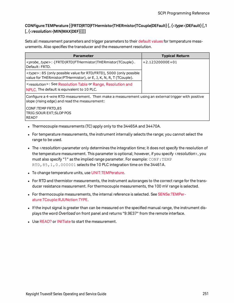
CONFigure:TEMPerature [FRTD|RTD|FTHermistor|THERmistor|TCouple|DEFault [, <type>|DEFault [,1[, <resolution>|MIN|MAX|DEF]]]]
Sets all measurement parameters and trigger parameters to their default values for temperature meas-urements. Also specifies the transducer and the measurement resolution.
Parameter Typical Return
<probe_type>: FRTD|RTD|FTHermistor|THERmistor|TCouple.Default: FRTD.
+2.12320000E+01
<type>: 85 (only possible value for RTD/FRTD), 5000 (only possiblevalue for THERmistor/FTHermistor), or E, J, K, N, R, T (TCouple).
<resolution>: See Resolution Table or Range, Resolution andNPLC. The default is equivalent to 10 PLC.
Configure a 4-wire RTD measurement. Then make a measurement using an external trigger with positiveslope (rising edge) and read the measurement:
CONF:TEMP FRTD,85TRIG:SOUR EXT;SLOP POSREAD?
l Thermocouple measurements (TC) apply only to the 34465A and 34470A.
l For temperature measurements, the instrument internally selects the range; you cannot select therange to be used.
l The <resolution>parameter only determines the integration time; it does not specify the resolution ofthe temperature measurement. This parameter is optional; however, if you specify <resolution>, youmust also specify "1" as the implied range parameter. For example: CONF:TEMPRTD,85,1,0.000001 selects the 10 PLC integration time on the 34461A.
l To change temperature units, use UNIT:TEMPerature.
l For RTD and thermistor measurements, the instrument autoranges to the correct range for the trans-ducer resistance measurement. For thermocouple measurements, the 100 mV range is selected.
l For thermocouple measurements, the internal reference is selected. See SENSe:TEMPer-ature:TCouple:RJUNction:TYPE.
l If the input signal is greater than can be measured on the specified manual range, the instrument dis-plays the word Overload on front panel and returns "9.9E37" from the remote interface.
l Use READ? or INITiate to start the measurement.
Keysight Truevolt Series Operating and Service Guide 251
SCPI Programming Reference
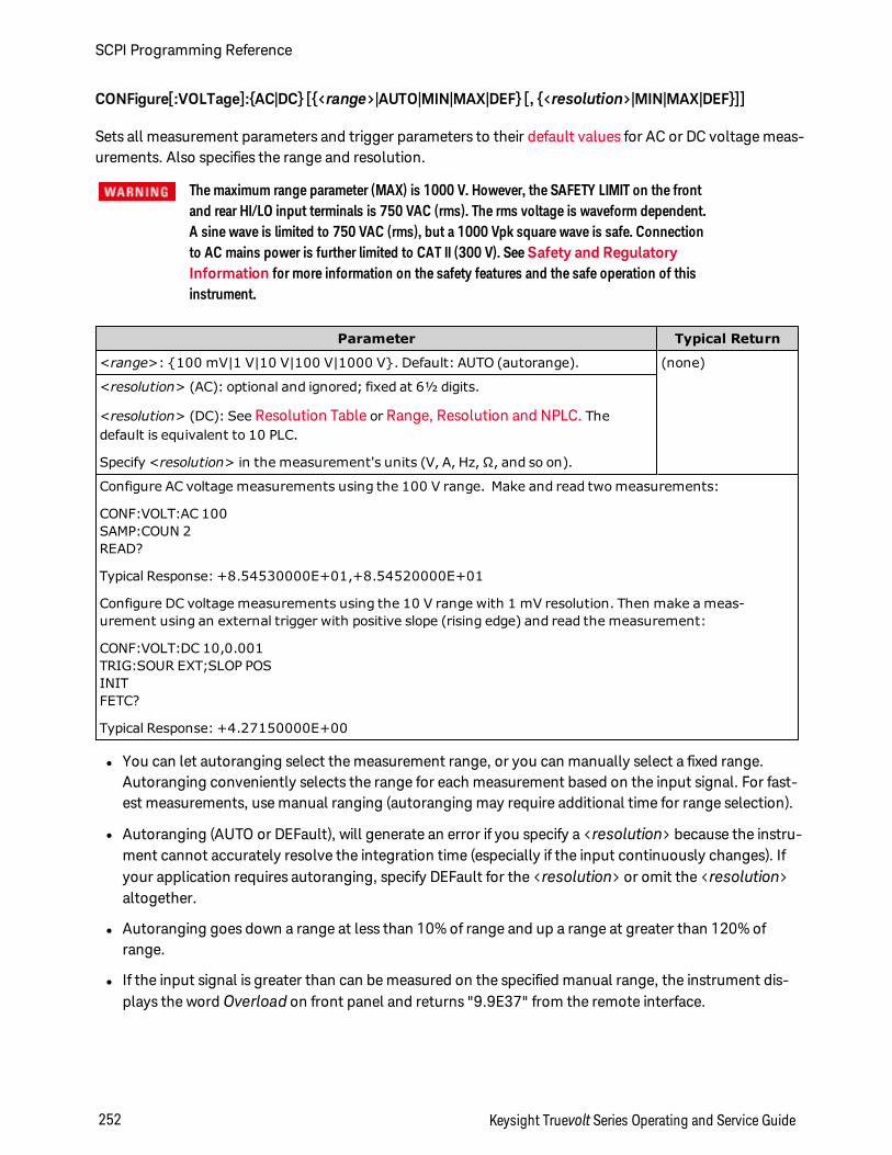
CONFigure[:VOLTage]:AC|DC [<range>|AUTO|MIN|MAX|DEF [, <resolution>|MIN|MAX|DEF]]
Sets all measurement parameters and trigger parameters to their default values for AC or DC voltage meas-urements. Also specifies the range and resolution.
The maximum range parameter (MAX) is 1000 V. However, the SAFETY LIMIT on the frontand rear HI/LO input terminals is 750 VAC (rms). The rms voltage is waveform dependent.A sine wave is limited to 750 VAC (rms), but a 1000 Vpk square wave is safe. Connectionto AC mains power is further limited to CAT II (300 V). SeeSafety and RegulatoryInformation for more information on the safety features and the safe operation of thisinstrument.
Parameter Typical Return
<range>: 100 mV|1 V|10 V|100 V|1000 V. Default: AUTO (autorange). (none)
<resolution> (AC): optional and ignored; fixed at 6½ digits.
<resolution> (DC): See Resolution Table or Range, Resolution and NPLC. Thedefault is equivalent to 10 PLC.
Specify <resolution> in the measurement's units (V, A, Hz, Ω, and so on).
Configure AC voltage measurements using the 100 V range. Make and read two measurements:
CONF:VOLT:AC 100SAMP:COUN 2READ?
Typical Response: +8.54530000E+01,+8.54520000E+01
Configure DC voltage measurements using the 10 V range with 1 mV resolution. Then make a meas-urement using an external trigger with positive slope (rising edge) and read the measurement:
CONF:VOLT:DC 10,0.001TRIG:SOUR EXT;SLOP POSINITFETC?
Typical Response: +4.27150000E+00
l You can let autoranging select the measurement range, or you can manually select a fixed range.Autoranging conveniently selects the range for each measurement based on the input signal. For fast-est measurements, use manual ranging (autoranging may require additional time for range selection).
l Autoranging (AUTO or DEFault), will generate an error if you specify a <resolution> because the instru-ment cannot accurately resolve the integration time (especially if the input continuously changes). Ifyour application requires autoranging, specify DEFault for the <resolution> or omit the <resolution>altogether.
l Autoranging goes down a range at less than 10% of range and up a range at greater than 120% ofrange.
l If the input signal is greater than can be measured on the specified manual range, the instrument dis-plays the word Overload on front panel and returns "9.9E37" from the remote interface.
SCPI Programming Reference
252 Keysight Truevolt Series Operating and Service Guide
l To control the measurement rate for AC measurements, change the trigger delay or AC filter band-width.
l Use READ? or INITiate to start the measurement.
See Also
CONFigure?
MEASure[:VOLTage]:AC|DC?
[SENSe:]CURRent:AC:BANDwidth
Keysight Truevolt Series Operating and Service Guide 253
SCPI Programming Reference
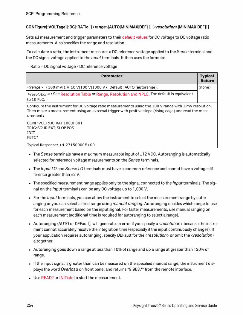
CONFigure[:VOLTage][:DC]:RATio [<range>|AUTO|MIN|MAX|DEF [, <resolution>|MIN|MAX|DEF]]
Sets all measurement and trigger parameters to their default values for DC voltage to DC voltage ratiomeasurements. Also specifies the range and resolution.
To calculate a ratio, the instrument measures a DC reference voltage applied to the Sense terminal andthe DC signal voltage applied to the Input terminals. It then uses the formula:
Ratio = DC signal voltage / DC reference voltage
Parameter TypicalReturn
<range>: 100 mV|1 V|10 V|100 V|1000 V. Default: AUTO (autorange). (none)
<resolution>: See Resolution Table or Range, Resolution and NPLC. The default is equivalentto 10 PLC.
Configure the instrument for DC voltage ratio measurements using the 100 V range with 1 mV resolution.Then make a measurement using an external trigger with positive slope (rising edge) and read the meas-urement:
CONF:VOLT:DC:RAT 100,0.001TRIG:SOUR EXT;SLOP POSINITFETC?
Typical Response: +4.27150000E+00
l The Sense terminals have a maximum measurable input of ±12 VDC. Autoranging is automaticallyselected for reference voltage measurements on the Sense terminals.
l The Input LO and Sense LO terminals must have a common reference and cannot have a voltage dif-ference greater than ±2 V.
l The specified measurement range applies only to the signal connected to the Input terminals. The sig-nal on the Input terminals can be any DC voltage up to 1,000 V.
l For the Input terminals, you can allow the instrument to select the measurement range by autor-anging or you can select a fixed range using manual ranging. Autoranging decides which range to usefor each measurement based on the input signal. For faster measurements, use manual ranging oneach measurement (additional time is required for autoranging to select a range).
l Autoranging (AUTO or DEFault), will generate an error if you specify a <resolution> because the instru-ment cannot accurately resolve the integration time (especially if the input continuously changes). Ifyour application requires autoranging, specify DEFault for the <resolution> or omit the <resolution>altogether.
l Autoranging goes down a range at less than 10% of range and up a range at greater than 120% ofrange.
l If the input signal is greater than can be measured on the specified manual range, the instrument dis-plays the word Overload on front panel and returns "9.9E37" from the remote interface.
l Use READ? or INITiate to start the measurement.
SCPI Programming Reference
254 Keysight Truevolt Series Operating and Service Guide
See Also
CONFigure?
MEASure[:VOLTage][:DC]:RATio?
Keysight Truevolt Series Operating and Service Guide 255
SCPI Programming Reference
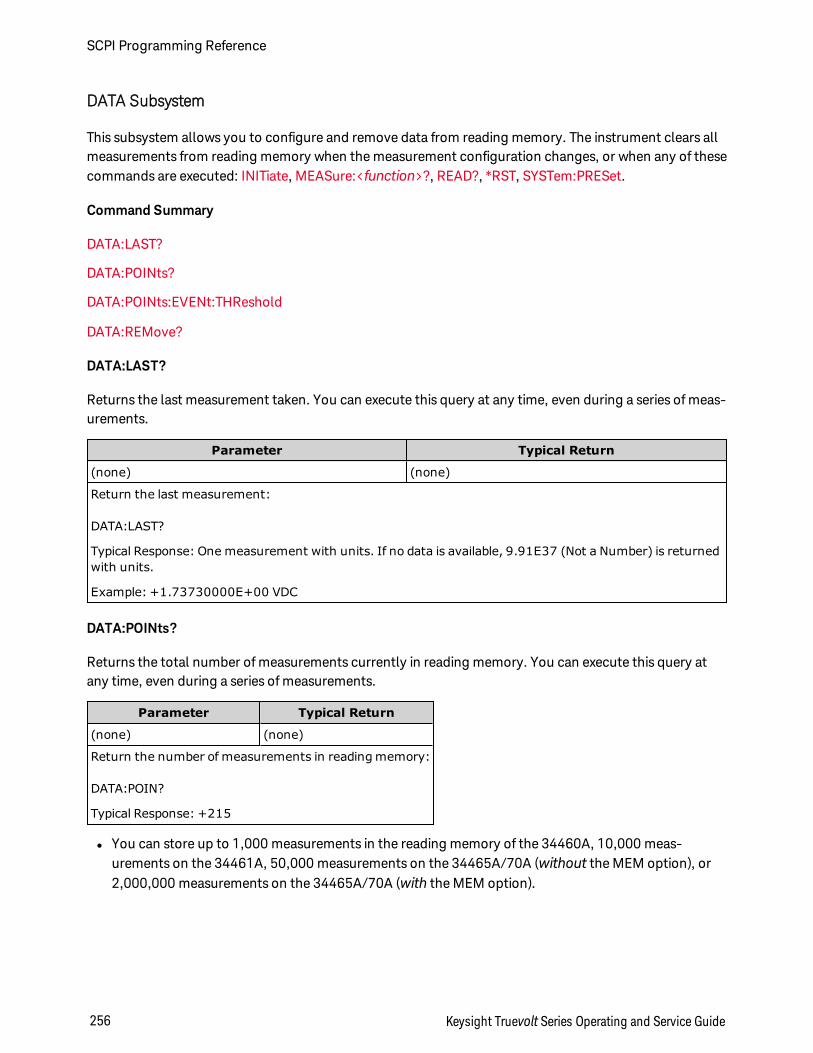
DATA Subsystem
This subsystem allows you to configure and remove data from reading memory. The instrument clears allmeasurements from reading memory when the measurement configuration changes, or when any of thesecommands are executed: INITiate, MEASure:<function>?, READ?, *RST, SYSTem:PRESet.
Command Summary
DATA:LAST?
DATA:POINts?
DATA:POINts:EVENt:THReshold
DATA:REMove?
DATA:LAST?
Returns the last measurement taken. You can execute this query at any time, even during a series of meas-urements.
Parameter Typical Return
(none) (none)
Return the last measurement:
DATA:LAST?
Typical Response: One measurement with units. If no data is available, 9.91E37 (Not a Number) is returnedwith units.
Example: +1.73730000E+00 VDC
DATA:POINts?
Returns the total number of measurements currently in reading memory. You can execute this query atany time, even during a series of measurements.
Parameter Typical Return
(none) (none)
Return the number of measurements in reading memory:
DATA:POIN?
Typical Response: +215
l You can store up to 1,000 measurements in the reading memory of the 34460A, 10,000 meas-urements on the 34461A, 50,000 measurements on the 34465A/70A (without the MEM option), or2,000,000 measurements on the 34465A/70A (with the MEM option).
SCPI Programming Reference
256 Keysight Truevolt Series Operating and Service Guide
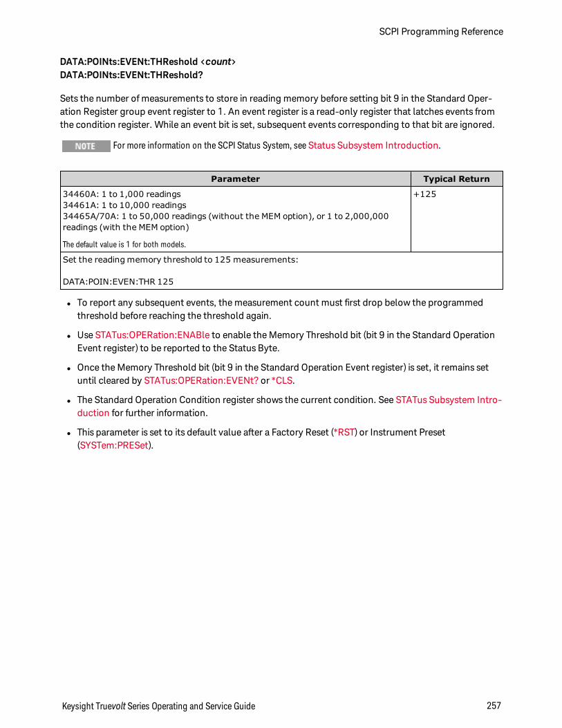
DATA:POINts:EVENt:THReshold <count>DATA:POINts:EVENt:THReshold?
Sets the number of measurements to store in reading memory before setting bit 9 in the Standard Oper-ation Register group event register to 1. An event register is a read-only register that latches events fromthe condition register. While an event bit is set, subsequent events corresponding to that bit are ignored.
For more information on the SCPI Status System, see Status Subsystem Introduction.
Parameter Typical Return
34460A: 1 to 1,000 readings34461A: 1 to 10,000 readings34465A/70A: 1 to 50,000 readings (without the MEM option), or 1 to 2,000,000readings (with the MEM option)
The default value is 1 for both models.
+125
Set the reading memory threshold to 125 measurements:
DATA:POIN:EVEN:THR 125
l To report any subsequent events, the measurement count must first drop below the programmedthreshold before reaching the threshold again.
l Use STATus:OPERation:ENABle to enable the Memory Threshold bit (bit 9 in the Standard OperationEvent register) to be reported to the Status Byte.
l Once the Memory Threshold bit (bit 9 in the Standard Operation Event register) is set, it remains setuntil cleared by STATus:OPERation:EVENt? or *CLS.
l The Standard Operation Condition register shows the current condition. See STATus Subsystem Intro-duction for further information.
l This parameter is set to its default value after a Factory Reset (*RST) or Instrument Preset(SYSTem:PRESet).
Keysight Truevolt Series Operating and Service Guide 257
SCPI Programming Reference

DATA:REMove? <num_readings> [,WAIT]
Reads and erases <num_readings> measurements from the reading memory. If fewer than <num_read-ings> measurements are available, the query returns an error unless the WAIT parameter is specified, inwhich case the query waits until <num_readings measurements are available.
Parameter Typical Return
34460A: 1 to 1,000 readings34461A: 1 to 10,000 readings34465A/70A: 1 to 50,000 readings (without the MEM option), or 1 to2,000,000 readings (with the MEM option)
(none)
Read and erase the three oldest readings from reading memory:
DATA:REMove? 3
Typical Response: -4.97215654E-01,-4.97343268E-01,-4.97121213E-01
l The R? and DATA:REMove? queries can be used during a long series of readings to periodically removereadings from memory that would normally cause the reading memory to overflow. R? does not waitfor all readings to complete. It sends the readings that are complete at the time the instrumentreceives the command. Use Read? or Fetch? if you want the instrument to wait until all readings arecomplete before sending readings.
l You can store up to 1,000 measurements in the reading memory of the 34460A, 10,000 meas-urements on the 34461A, 50,000 measurements on the 34465A/70A (without the MEM option), or2,000,000 measurements on the 34465A/70A (with the MEM option). If reading memory overflows,new measurements overwrite the oldest measurements stored; the most recent measurements arealways preserved. No error is generated, but the Reading Mem Ovfl bit (bit 14) is set in the Ques-tionable Data Register's condition register (see Status System Introduction).
SCPI Programming Reference
258 Keysight Truevolt Series Operating and Service Guide
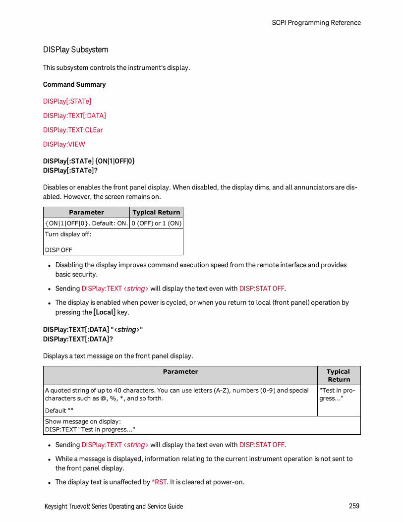
DISPlay Subsystem
This subsystem controls the instrument's display.
Command Summary
DISPlay[:STATe]
DISPlay:TEXT[:DATA]
DISPlay:TEXT:CLEar
DISPlay:VIEW
DISPlay[:STATe] ON|1|OFF|0DISPlay[:STATe]?
Disables or enables the front panel display. When disabled, the display dims, and all annunciators are dis-abled. However, the screen remains on.
Parameter Typical Return
ON|1|OFF|0. Default: ON. 0 (OFF) or 1 (ON)
Turn display off:
DISP OFF
l Disabling the display improves command execution speed from the remote interface and providesbasic security.
l Sending DISPlay:TEXT <string> will display the text even with DISP:STAT OFF.
l The display is enabled when power is cycled, or when you return to local (front panel) operation bypressing the [Local] key.
DISPlay:TEXT[:DATA] "<string>"DISPlay:TEXT[:DATA]?
Displays a text message on the front panel display.
Parameter TypicalReturn
A quoted string of up to 40 characters. You can use letters (A-Z), numbers (0-9) and specialcharacters such as @, %, *, and so forth.
Default ""
"Test in pro-gress..."
Show message on display:DISP:TEXT "Test in progress..."
l Sending DISPlay:TEXT <string> will display the text even with DISP:STAT OFF.
l While a message is displayed, information relating to the current instrument operation is not sent tothe front panel display.
l The display text is unaffected by *RST. It is cleared at power-on.
Keysight Truevolt Series Operating and Service Guide 259
SCPI Programming Reference
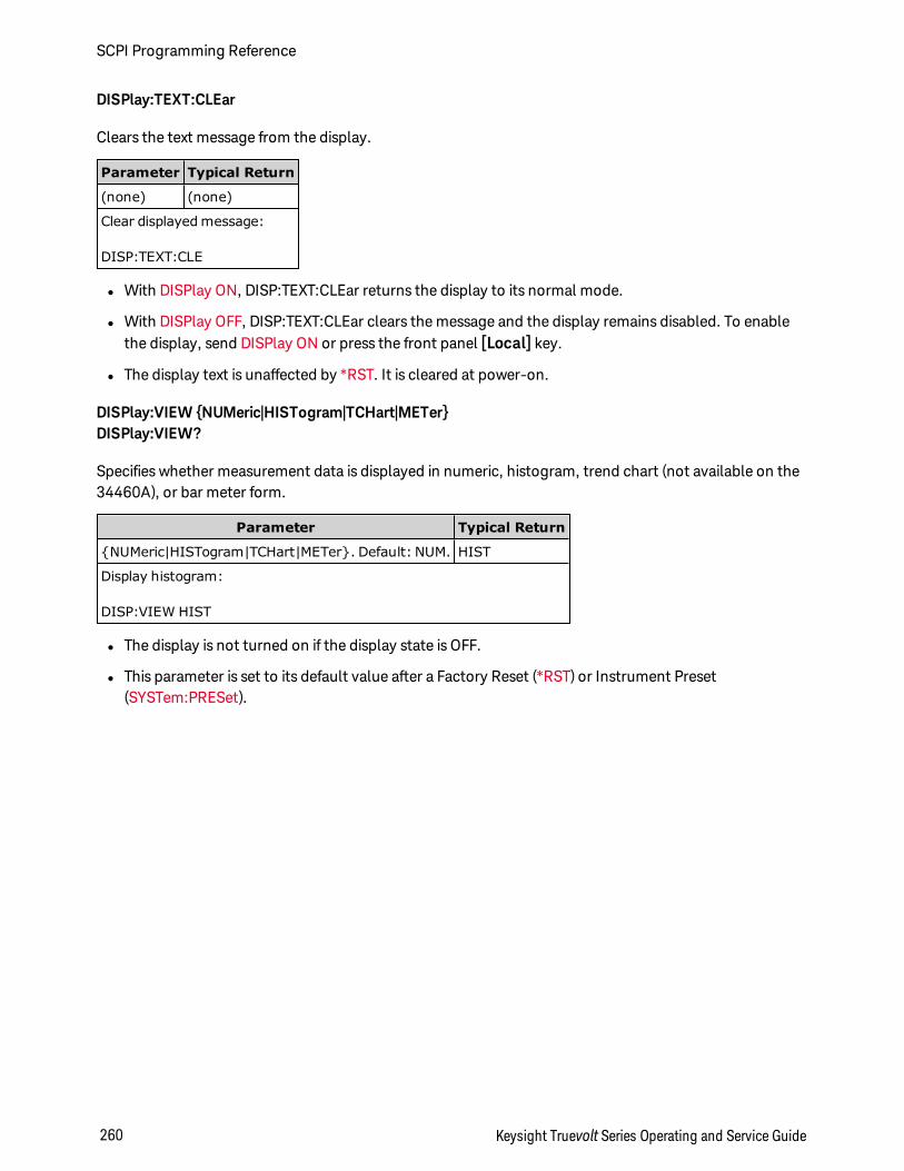
DISPlay:TEXT:CLEar
Clears the text message from the display.
Parameter Typical Return
(none) (none)
Clear displayed message:
DISP:TEXT:CLE
l With DISPlay ON, DISP:TEXT:CLEar returns the display to its normal mode.
l With DISPlay OFF, DISP:TEXT:CLEar clears the message and the display remains disabled. To enablethe display, send DISPlay ON or press the front panel [Local] key.
l The display text is unaffected by *RST. It is cleared at power-on.
DISPlay:VIEW NUMeric|HISTogram|TCHart|METerDISPlay:VIEW?
Specifies whether measurement data is displayed in numeric, histogram, trend chart (not available on the34460A), or bar meter form.
Parameter Typical Return
NUMeric|HISTogram|TCHart|METer. Default: NUM. HIST
Display histogram:
DISP:VIEW HIST
l The display is not turned on if the display state is OFF.
l This parameter is set to its default value after a Factory Reset (*RST) or Instrument Preset(SYSTem:PRESet).
SCPI Programming Reference
260 Keysight Truevolt Series Operating and Service Guide
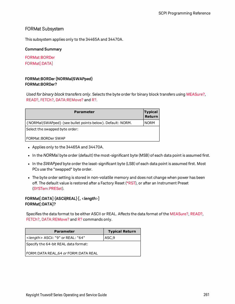
FORMat Subsystem
This subsystem applies only to the 34465A and 34470A.
Command Summary
FORMat:BORDer
FORMat[:DATA]
FORMat:BORDer NORMal|SWAPpedFORMat:BORDer?
Used for binary block transfers only. Selects the byte order for binary block transfers using MEASure?,READ?, FETCh?, DATA:REMove? and R?.
Parameter TypicalReturn
NORMal|SWAPped (see bullet points below). Default: NORM. NORM
Select the swapped byte order:
FORMat:BORDer SWAP
l Applies only to the 34465A and 34470A.
l In theNORMal byte order (default) the most-significant byte (MSB) of each data point is assumed first.
l In the SWAPped byte order the least-significant byte (LSB) of each data point is assumed first. MostPCs use the "swapped" byte order.
l The byte order setting is stored in non-volatile memory and does not change when power has beenoff. The default value is restored after a Factory Reset (*RST), or after an Instrument Preset(SYSTem:PRESet).
FORMat[:DATA] ASCii|REAL [, <length>]FORMat[:DATA]?
Specifies the data format to be either ASCII or REAL. Affects the data format of the MEASure?, READ?,FETCh?, DATA:REMove? and R? commands only.
Parameter Typical Return
<length> ASCii: "9" or REAL: "64" ASC,9
Specify the 64-bit REAL data format:
FORM:DATA REAL,64 or FORM:DATA REAL
Keysight Truevolt Series Operating and Service Guide 261
SCPI Programming Reference
l Applies only to the 34465A and 34470A.
l If ASCii is specified, numeric data is transferred as ASCii characters. The numbers are separated by com-mas as specified in IEEE 488.2. The <length> parameter is optional, but "9" is the default and onlyallowed value, and the instrument returns 9 significant digits (for example: +4.57553816E-05).
l If REAL is specified, numeric data is transferred as REAL binary data in IEEE 488.2 definite-lengthblock format. The <length> parameter is optional, but "64" is the default and only allowed value. Thebyte order is controlled by FORMat:BORDer.
SCPI Programming Reference
262 Keysight Truevolt Series Operating and Service Guide
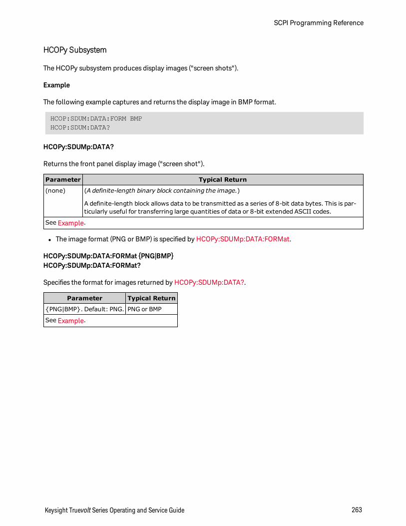
HCOPy Subsystem
The HCOPy subsystem produces display images ("screen shots").
Example
The following example captures and returns the display image in BMP format.
HCOP:SDUM:DATA:FORM BMPHCOP:SDUM:DATA?
HCOPy:SDUMp:DATA?
Returns the front panel display image ("screen shot").
Parameter Typical Return
(none) (A definite-length binary block containing the image.)
A definite-length block allows data to be transmitted as a series of 8-bit data bytes. This is par-ticularly useful for transferring large quantities of data or 8-bit extended ASCII codes.
See Example.
l The image format (PNG or BMP) is specified by HCOPy:SDUMp:DATA:FORMat.
HCOPy:SDUMp:DATA:FORMat PNG|BMPHCOPy:SDUMp:DATA:FORMat?
Specifies the format for images returned by HCOPy:SDUMp:DATA?.
Parameter Typical Return
PNG|BMP. Default: PNG. PNG or BMP
See Example.
Keysight Truevolt Series Operating and Service Guide 263
SCPI Programming Reference
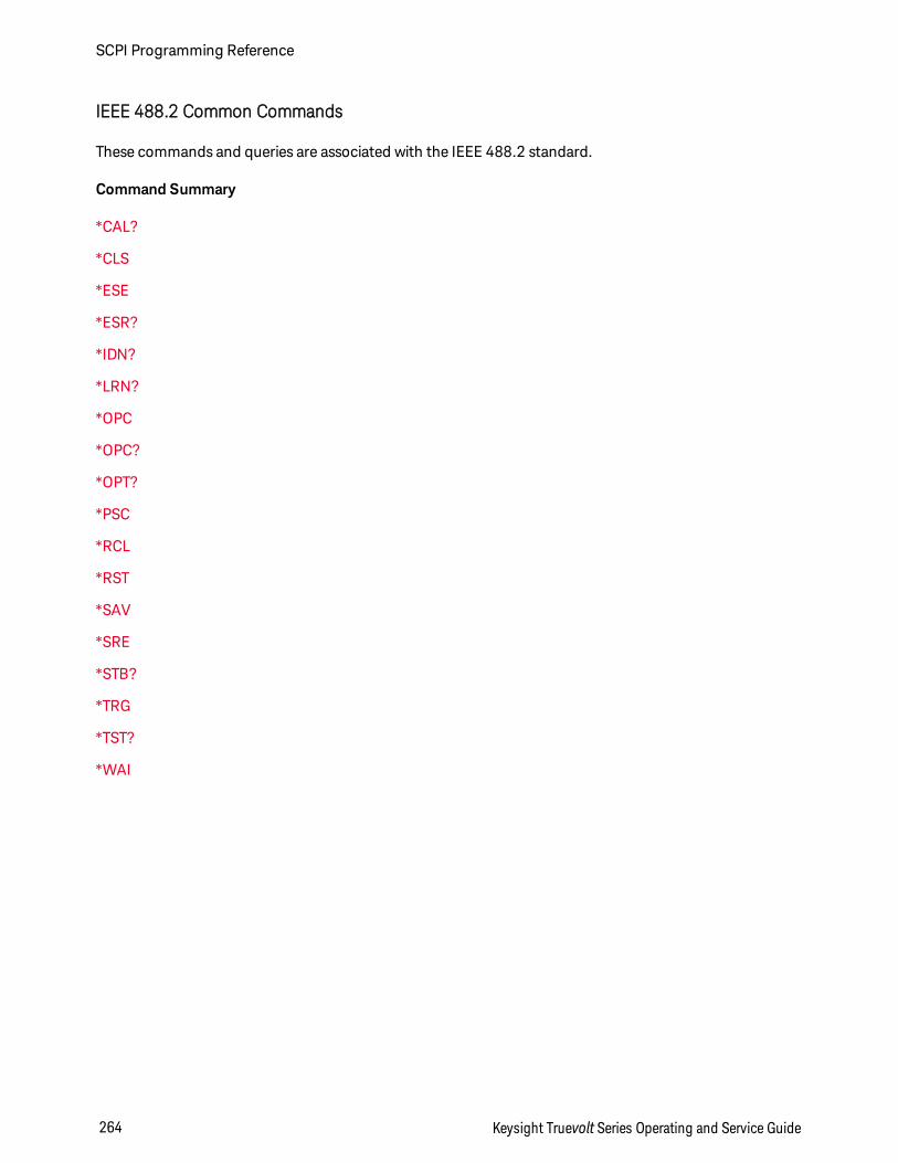
IEEE 488.2 Common Commands
These commands and queries are associated with the IEEE 488.2 standard.
Command Summary
*CAL?
*CLS
*ESE
*ESR?
*IDN?
*LRN?
*OPC
*OPC?
*OPT?
*PSC
*RCL
*RST
*SAV
*SRE
*STB?
*TRG
*TST?
*WAI
SCPI Programming Reference
264 Keysight Truevolt Series Operating and Service Guide
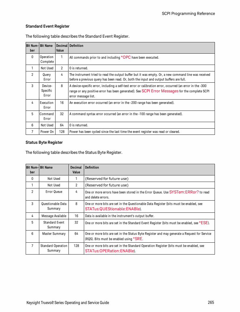
Standard Event Register
The following table describes the Standard Event Register.
Bit Num-ber
Bit Name DecimalValue
Definition
0 OperationComplete
1 All commands prior to and including *OPC have been executed.
1 Not Used 2 0 is returned.
2 QueryError
4 The instrument tried to read the output buffer but it was empty. Or, a new command line was receivedbefore a previous query has been read. Or, both the input and output buffers are full.
3 Device-SpecificError
8 A device-specific error, including a self-test error or calibration error, occurred (an error in the -300
range or any positive error has been generated). See SCPI Error Messages for the complete SCPIerror message list.
4 ExecutionError
16 An execution error occurred (an error in the -200 range has been generated).
5 CommandError
32 A command syntax error occurred (an error in the -100 range has been generated).
6 Not Used 64 0 is returned.
7 Power On 128 Power has been cycled since the last time the event register was read or cleared.
Status Byte Register
The following table describes the Status Byte Register.
Bit Num-ber
Bit Name DecimalValue
Definition
0 Not Used 1 (Reserved for future use)
1 Not Used 2 (Reserved for future use)
2 Error Queue 4 One or more errors have been stored in the Error Queue. Use SYSTem:ERRor? to readand delete errors.
3 Questionable DataSummary
8 One or more bits are set in the Questionable Data Register (bits must be enabled, see
STATus:QUEStionable:ENABle).
4 Message Available 16 Data is available in the instrument's output buffer.
5 Standard EventSummary
32 One or more bits are set in the Standard Event Register (bits must be enabled, see *ESE).
6 Master Summary 64 One or more bits are set in the Status Byte Register and may generate a Request for Service
(RQS). Bits must be enabled using *SRE.
7 Standard OperationSummary
128 One or more bits are set in the Standard Operation Register (bits must be enabled, see
STATus:OPERation:ENABle).
Keysight Truevolt Series Operating and Service Guide 265
SCPI Programming Reference
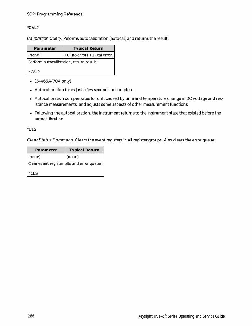
*CAL?
Calibration Query. Peforms autocalibration (autocal) and returns the result.
Parameter Typical Return
(none) +0 (no error) +1 (cal error)
Perform autocalibration, return result:
*CAL?
l (34465A/70A only)
l Autocalibration takes just a few seconds to complete.
l Autocalibration compensates for drift caused by time and temperature change in DC voltage and res-istance measurements, and adjusts some aspects of other measurement functions.
l Following the autocalibration, the instrument returns to the instrument state that existed before theautocalibration.
*CLS
Clear Status Command. Clears the event registers in all register groups. Also clears the error queue.
Parameter Typical Return
(none) (none)
Clear event register bits and error queue:
*CLS
SCPI Programming Reference
266 Keysight Truevolt Series Operating and Service Guide
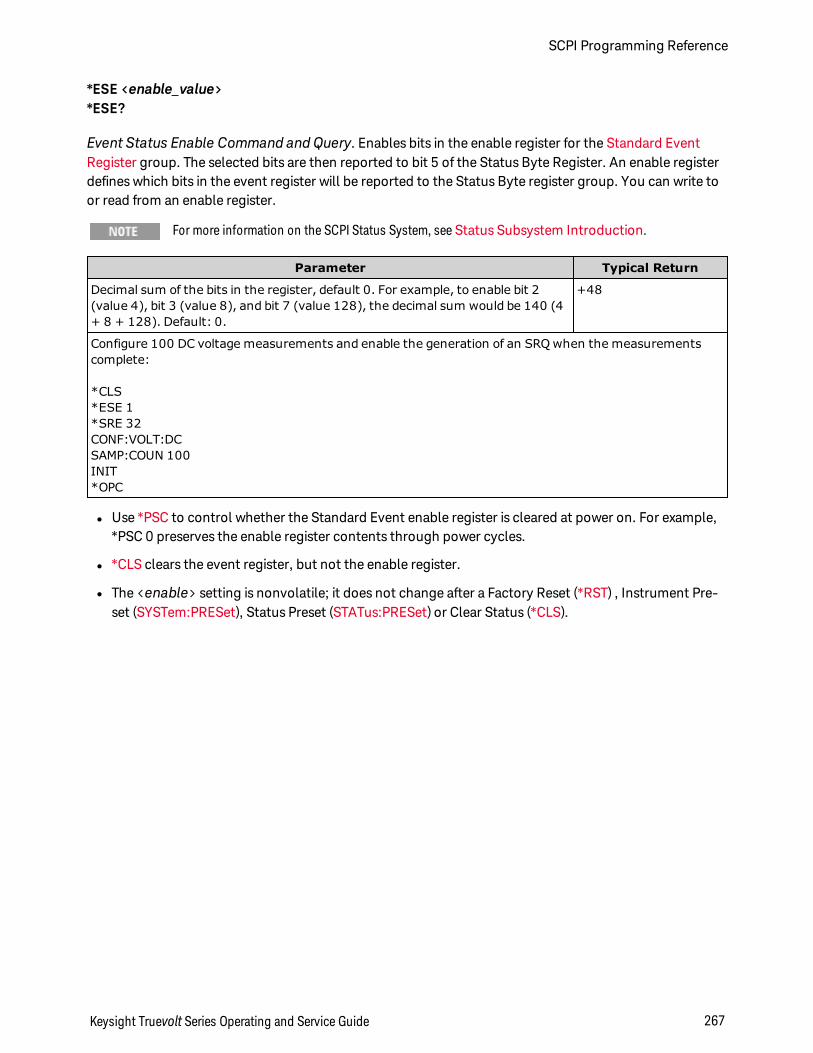
*ESE <enable_value>*ESE?
Event Status Enable Command and Query. Enables bits in the enable register for the Standard EventRegister group. The selected bits are then reported to bit 5 of the Status Byte Register. An enable registerdefines which bits in the event register will be reported to the Status Byte register group. You can write toor read from an enable register.
For more information on the SCPI Status System, see Status Subsystem Introduction.
Parameter Typical Return
Decimal sum of the bits in the register, default 0. For example, to enable bit 2(value 4), bit 3 (value 8), and bit 7 (value 128), the decimal sum would be 140 (4+ 8 + 128). Default: 0.
+48
Configure 100 DC voltage measurements and enable the generation of an SRQ when the measurementscomplete:
*CLS*ESE 1*SRE 32CONF:VOLT:DCSAMP:COUN 100INIT*OPC
l Use *PSC to control whether the Standard Event enable register is cleared at power on. For example,*PSC 0 preserves the enable register contents through power cycles.
l *CLS clears the event register, but not the enable register.
l The <enable> setting is nonvolatile; it does not change after a Factory Reset (*RST) , Instrument Pre-set (SYSTem:PRESet), Status Preset (STATus:PRESet) or Clear Status (*CLS).
Keysight Truevolt Series Operating and Service Guide 267
SCPI Programming Reference
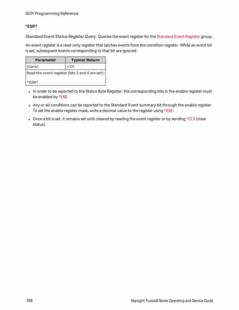
*ESR?
Standard Event Status Register Query. Queries the event register for the Standard Event Register group.
An event register is a read-only register that latches events from the condition register. While an event bitis set, subsequent events corresponding to that bit are ignored.
Parameter Typical Return
(none) +24
Read the event register (bits 3 and 4 are set):
*ESR?
l In order to be reported to the Status Byte Register, the corresponding bits in the enable register mustbe enabled by *ESE.
l Any or all conditions can be reported to the Standard Event summary bit through the enable register.To set the enable register mask, write a decimal value to the register using *ESE.
l Once a bit is set, it remains set until cleared by reading the event register or by sending *CLS (clearstatus).
SCPI Programming Reference
268 Keysight Truevolt Series Operating and Service Guide
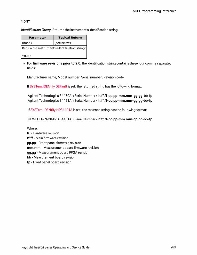
*IDN?
Identification Query. Returns the instrument’s identification string.
Parameter Typical Return
(none) (see below)
Return the instrument's identification string:
*IDN?
l For firmware revisions prior to 2.0, the identification string contains these four comma separatedfields:
Manufacturer name, Model number, Serial number, Revision code
If SYSTem:IDENtify DEFault is set, the returned string has the following format:
Agilent Technologies,34460A,<Serial Number>,h.ff.ff-pp.pp-mm.mm-gg.gg-bb-fpAgilent Technologies,34461A,<Serial Number>,h.ff.ff-pp.pp-mm.mm-gg.gg-bb-fp
If SYSTem:IDENtify HP34401A is set, the returned string has the following format:
HEWLETT-PACKARD,34401A,<Serial Number>,h.ff.ff-pp.pp-mm.mm-gg.gg-bb-fp
Where:h. - Hardware revisionff.ff - Main firmware revisionpp.pp - Front panel firmware revisionmm.mm - Measurement board firmware revisiongg.gg - Measurement board FPGA revisionbb - Measurement board revisionfp - Front panel board revision
Keysight Truevolt Series Operating and Service Guide 269
SCPI Programming Reference
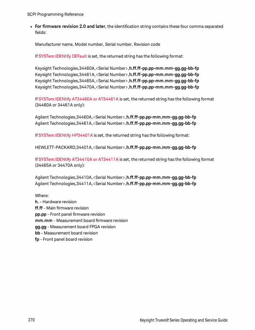
l For firmware revision 2.0 and later, the identification string contains these four comma separatedfields:
Manufacturer name, Model number, Serial number, Revision code
If SYSTem:IDENtify DEFault is set, the returned string has the following format:
Keysight Technologies,34460A,<Serial Number>,h.ff.ff-pp.pp-mm.mm-gg.gg-bb-fpKeysight Technologies,34461A,<Serial Number>,h.ff.ff-pp.pp-mm.mm-gg.gg-bb-fpKeysight Technologies,34465A,<Serial Number>,h.ff.ff-pp.pp-mm.mm-gg.gg-bb-fpKeysight Technologies,34470A,<Serial Number>,h.ff.ff-pp.pp-mm.mm-gg.gg-bb-fp
If SYSTem:IDENtify AT34460A or AT34461A is set, the returned string has the following format(34460A or 34461A only):
Agilent Technologies,34460A,<Serial Number>,h.ff.ff-pp.pp-mm.mm-gg.gg-bb-fpAgilent Technologies,34461A,<Serial Number>,h.ff.ff-pp.pp-mm.mm-gg.gg-bb-fp
If SYSTem:IDENtify HP34401A is set, the returned string has the following format:
HEWLETT-PACKARD,34401A,<Serial Number>,h.ff.ff-pp.pp-mm.mm-gg.gg-bb-fp
If SYSTem:IDENtify AT34410A or AT34411A is set, the returned string has the following format(34465A or 34470A only):
Agilent Technologies,34410A,<Serial Number>,h.ff.ff-pp.pp-mm.mm-gg.gg-bb-fpAgilent Technologies,34411A,<Serial Number>,h.ff.ff-pp.pp-mm.mm-gg.gg-bb-fp
Where:h. - Hardware revisionff.ff - Main firmware revisionpp.pp - Front panel firmware revisionmm.mm - Measurement board firmware revisiongg.gg - Measurement board FPGA revisionbb - Measurement board revisionfp - Front panel board revision
SCPI Programming Reference
270 Keysight Truevolt Series Operating and Service Guide
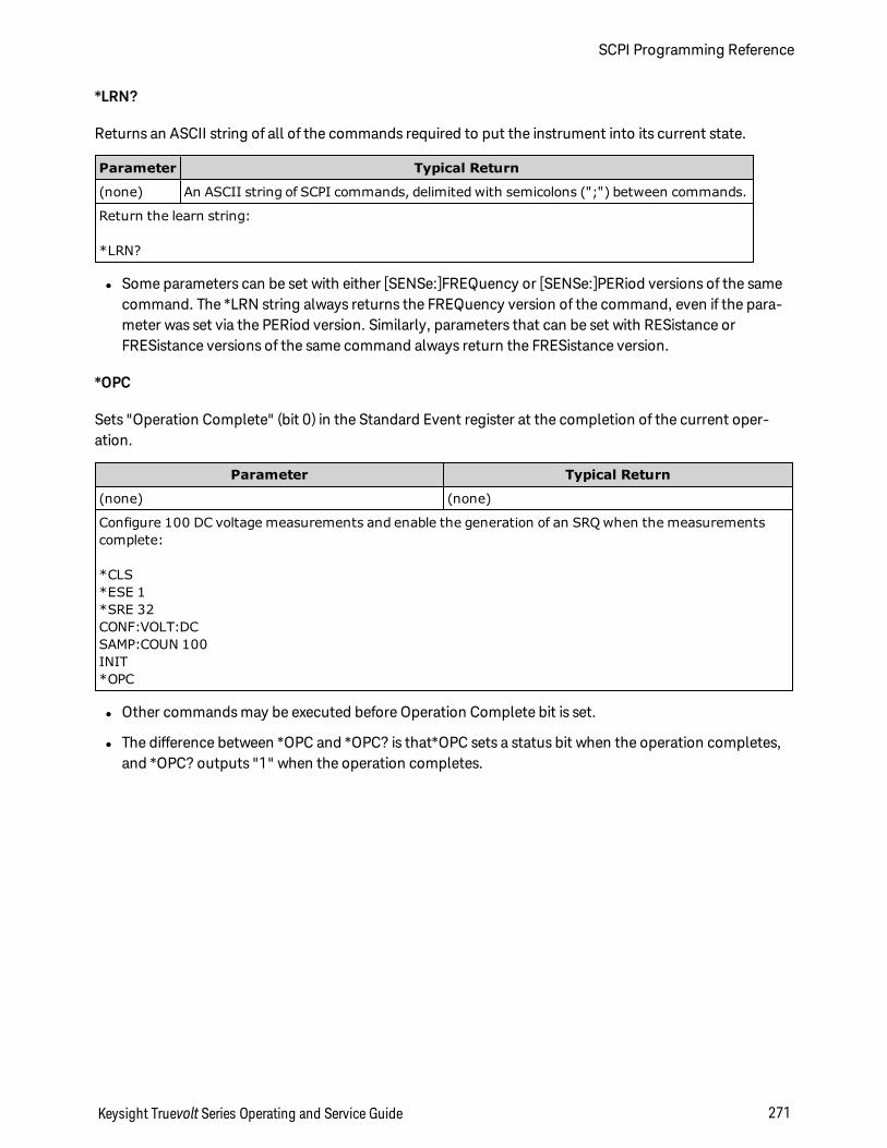
*LRN?
Returns an ASCII string of all of the commands required to put the instrument into its current state.
Parameter Typical Return
(none) An ASCII string of SCPI commands, delimited with semicolons (";") between commands.
Return the learn string:
*LRN?
l Some parameters can be set with either [SENSe:]FREQuency or [SENSe:]PERiod versions of the samecommand. The *LRN string always returns the FREQuency version of the command, even if the para-meter was set via the PERiod version. Similarly, parameters that can be set with RESistance orFRESistance versions of the same command always return the FRESistance version.
*OPC
Sets "Operation Complete" (bit 0) in the Standard Event register at the completion of the current oper-ation.
Parameter Typical Return
(none) (none)
Configure 100 DC voltage measurements and enable the generation of an SRQ when the measurementscomplete:
*CLS*ESE 1*SRE 32CONF:VOLT:DCSAMP:COUN 100INIT*OPC
l Other commands may be executed before Operation Complete bit is set.
l The difference between *OPC and *OPC? is that*OPC sets a status bit when the operation completes,and *OPC? outputs "1" when the operation completes.
Keysight Truevolt Series Operating and Service Guide 271
SCPI Programming Reference
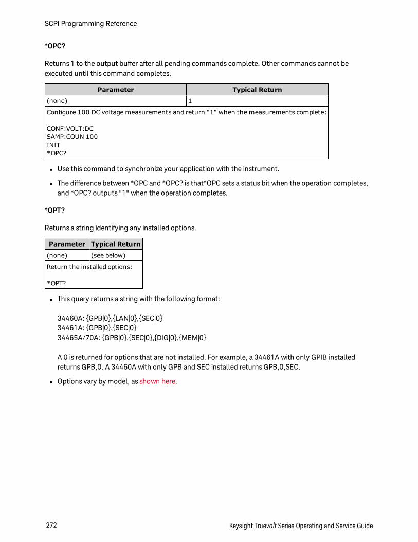
*OPC?
Returns 1 to the output buffer after all pending commands complete. Other commands cannot beexecuted until this command completes.
Parameter Typical Return
(none) 1
Configure 100 DC voltage measurements and return "1" when the measurements complete:
CONF:VOLT:DCSAMP:COUN 100INIT*OPC?
l Use this command to synchronize your application with the instrument.
l The difference between *OPC and *OPC? is that*OPC sets a status bit when the operation completes,and *OPC? outputs "1" when the operation completes.
*OPT?
Returns a string identifying any installed options.
Parameter Typical Return
(none) (see below)
Return the installed options:
*OPT?
l This query returns a string with the following format:
34460A: GPB|0,LAN|0,SEC|034461A: GPB|0,SEC|034465A/70A: GPB|0,SEC|0,DIG|0,MEM|0
A 0 is returned for options that are not installed. For example, a 34461A with only GPIB installedreturns GPB,0. A 34460A with only GPB and SEC installed returns GPB,0,SEC.
l Options vary by model, as shown here.
SCPI Programming Reference
272 Keysight Truevolt Series Operating and Service Guide
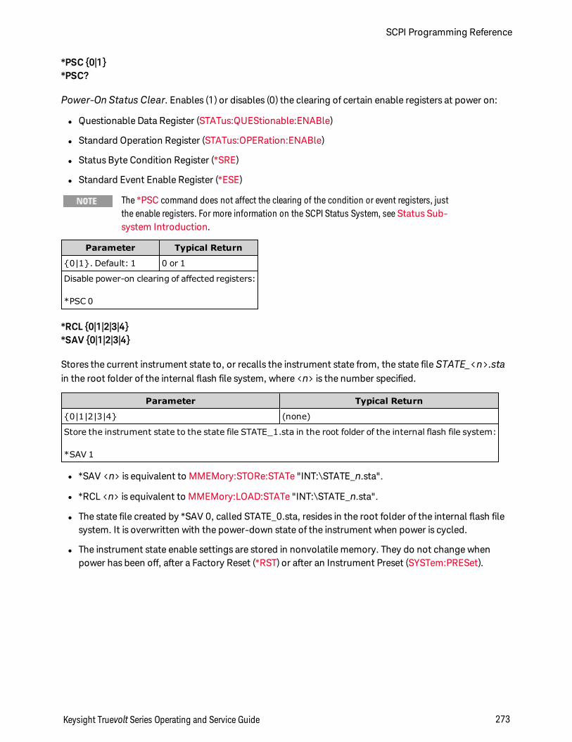
*PSC 0|1*PSC?
Power-On Status Clear. Enables (1) or disables (0) the clearing of certain enable registers at power on:
l Questionable Data Register (STATus:QUEStionable:ENABle)
l Standard Operation Register (STATus:OPERation:ENABle)
l Status Byte Condition Register (*SRE)
l Standard Event Enable Register (*ESE)
The *PSC command does not affect the clearing of the condition or event registers, justthe enable registers. For more information on the SCPI Status System, see Status Sub-system Introduction.
Parameter Typical Return
0|1. Default: 1 0 or 1
Disable power-on clearing of affected registers:
*PSC 0
*RCL 0|1|2|3|4*SAV 0|1|2|3|4
Stores the current instrument state to, or recalls the instrument state from, the state file STATE_<n>.stain the root folder of the internal flash file system, where <n> is the number specified.
Parameter Typical Return
0|1|2|3|4 (none)
Store the instrument state to the state file STATE_1.sta in the root folder of the internal flash file system:
*SAV 1
l *SAV <n> is equivalent to MMEMory:STORe:STATe "INT:\STATE_n.sta".
l *RCL <n> is equivalent to MMEMory:LOAD:STATe "INT:\STATE_n.sta".
l The state file created by *SAV 0, called STATE_0.sta, resides in the root folder of the internal flash filesystem. It is overwritten with the power-down state of the instrument when power is cycled.
l The instrument state enable settings are stored in nonvolatile memory. They do not change whenpower has been off, after a Factory Reset (*RST) or after an Instrument Preset (SYSTem:PRESet).
Keysight Truevolt Series Operating and Service Guide 273
SCPI Programming Reference
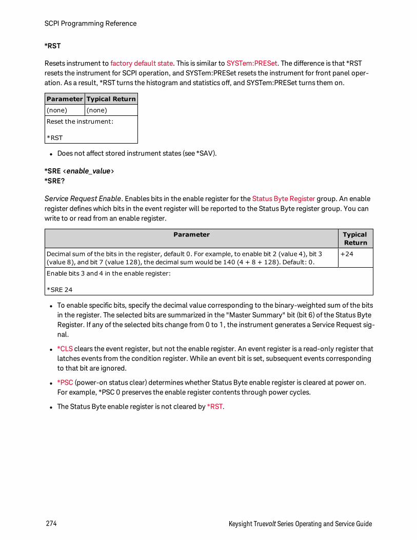
*RST
Resets instrument to factory default state. This is similar to SYSTem:PRESet. The difference is that *RSTresets the instrument for SCPI operation, and SYSTem:PRESet resets the instrument for front panel oper-ation. As a result, *RST turns the histogram and statistics off, and SYSTem:PRESet turns them on.
Parameter Typical Return
(none) (none)
Reset the instrument:
*RST
l Does not affect stored instrument states (see *SAV).
*SRE <enable_value>*SRE?
Service Request Enable. Enables bits in the enable register for the Status Byte Register group. An enableregister defines which bits in the event register will be reported to the Status Byte register group. You canwrite to or read from an enable register.
Parameter TypicalReturn
Decimal sum of the bits in the register, default 0. For example, to enable bit 2 (value 4), bit 3(value 8), and bit 7 (value 128), the decimal sum would be 140 (4 + 8 + 128). Default: 0.
+24
Enable bits 3 and 4 in the enable register:
*SRE 24
l To enable specific bits, specify the decimal value corresponding to the binary-weighted sum of the bitsin the register. The selected bits are summarized in the "Master Summary" bit (bit 6) of the Status ByteRegister. If any of the selected bits change from 0 to 1, the instrument generates a Service Request sig-nal.
l *CLS clears the event register, but not the enable register. An event register is a read-only register thatlatches events from the condition register. While an event bit is set, subsequent events correspondingto that bit are ignored.
l *PSC (power-on status clear) determines whether Status Byte enable register is cleared at power on.For example, *PSC 0 preserves the enable register contents through power cycles.
l The Status Byte enable register is not cleared by *RST.
SCPI Programming Reference
274 Keysight Truevolt Series Operating and Service Guide
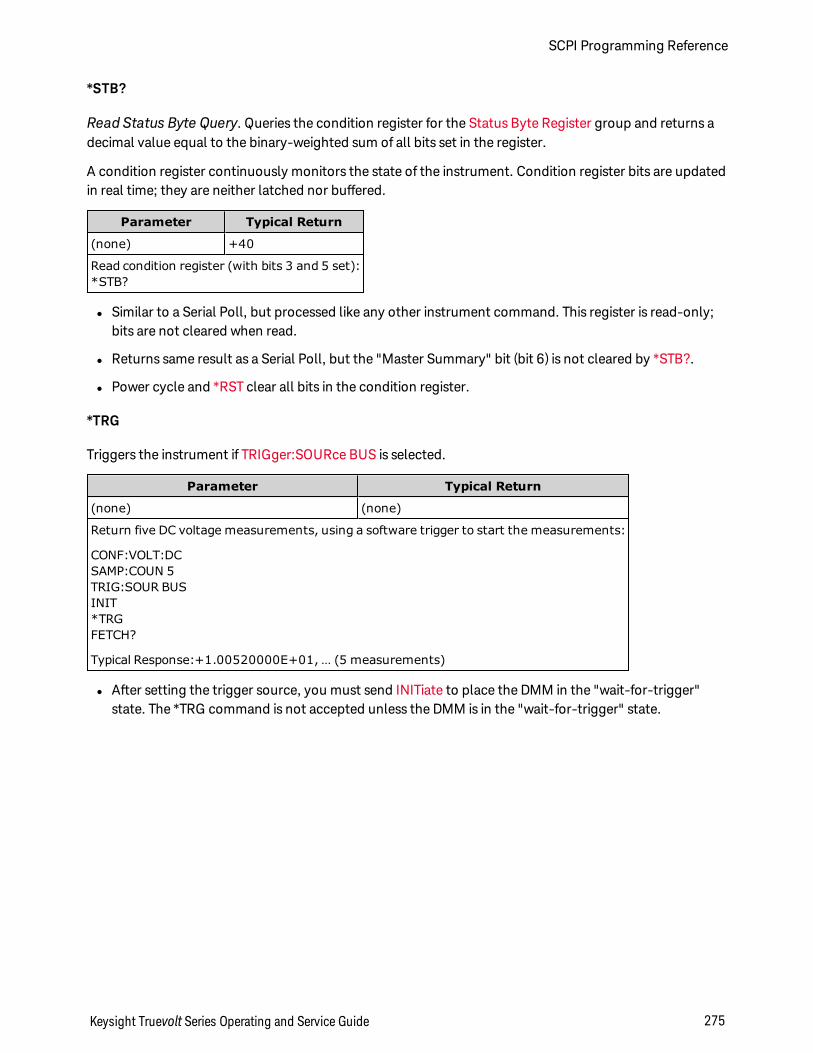
*STB?
Read Status Byte Query. Queries the condition register for the Status Byte Register group and returns adecimal value equal to the binary-weighted sum of all bits set in the register.
A condition register continuously monitors the state of the instrument. Condition register bits are updatedin real time; they are neither latched nor buffered.
Parameter Typical Return
(none) +40
Read condition register (with bits 3 and 5 set):*STB?
l Similar to a Serial Poll, but processed like any other instrument command. This register is read-only;bits are not cleared when read.
l Returns same result as a Serial Poll, but the "Master Summary" bit (bit 6) is not cleared by *STB?.
l Power cycle and *RST clear all bits in the condition register.
*TRG
Triggers the instrument if TRIGger:SOURce BUS is selected.
Parameter Typical Return
(none) (none)
Return five DC voltage measurements, using a software trigger to start the measurements:
CONF:VOLT:DCSAMP:COUN 5TRIG:SOUR BUSINIT*TRGFETCH?
Typical Response:+1.00520000E+01, … (5 measurements)
l After setting the trigger source, you must send INITiate to place the DMM in the "wait-for-trigger"state. The *TRG command is not accepted unless the DMM is in the "wait-for-trigger" state.
Keysight Truevolt Series Operating and Service Guide 275
SCPI Programming Reference
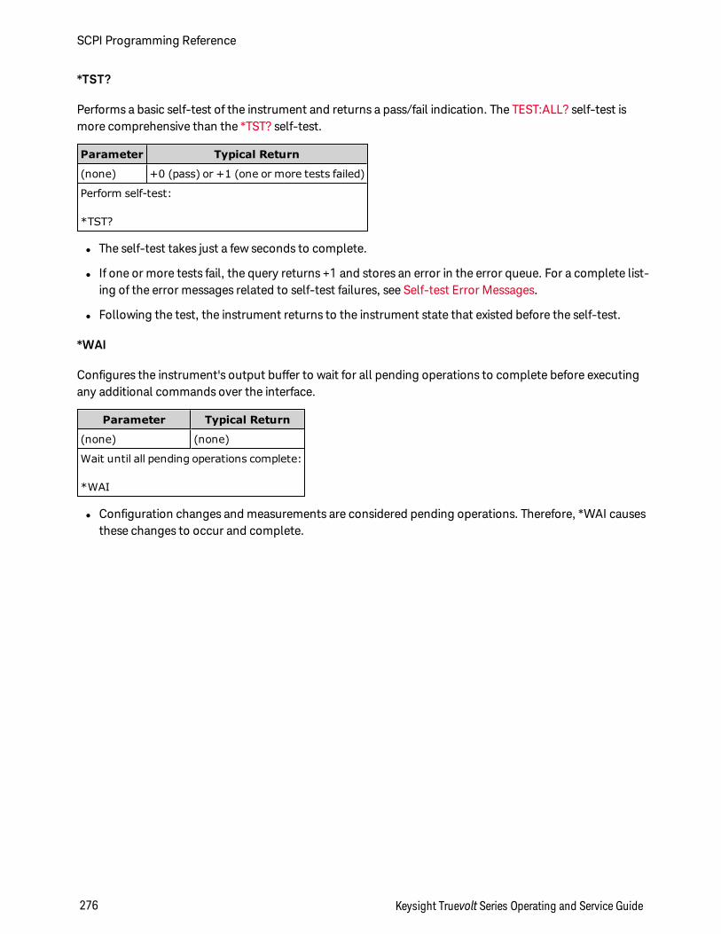
*TST?
Performs a basic self-test of the instrument and returns a pass/fail indication. The TEST:ALL? self-test ismore comprehensive than the *TST? self-test.
Parameter Typical Return
(none) +0 (pass) or +1 (one or more tests failed)
Perform self-test:
*TST?
l The self-test takes just a few seconds to complete.
l If one or more tests fail, the query returns +1 and stores an error in the error queue. For a complete list-ing of the error messages related to self-test failures, see Self-test Error Messages.
l Following the test, the instrument returns to the instrument state that existed before the self-test.
*WAI
Configures the instrument's output buffer to wait for all pending operations to complete before executingany additional commands over the interface.
Parameter Typical Return
(none) (none)
Wait until all pending operations complete:
*WAI
l Configuration changes and measurements are considered pending operations. Therefore, *WAI causesthese changes to occur and complete.
SCPI Programming Reference
276 Keysight Truevolt Series Operating and Service Guide
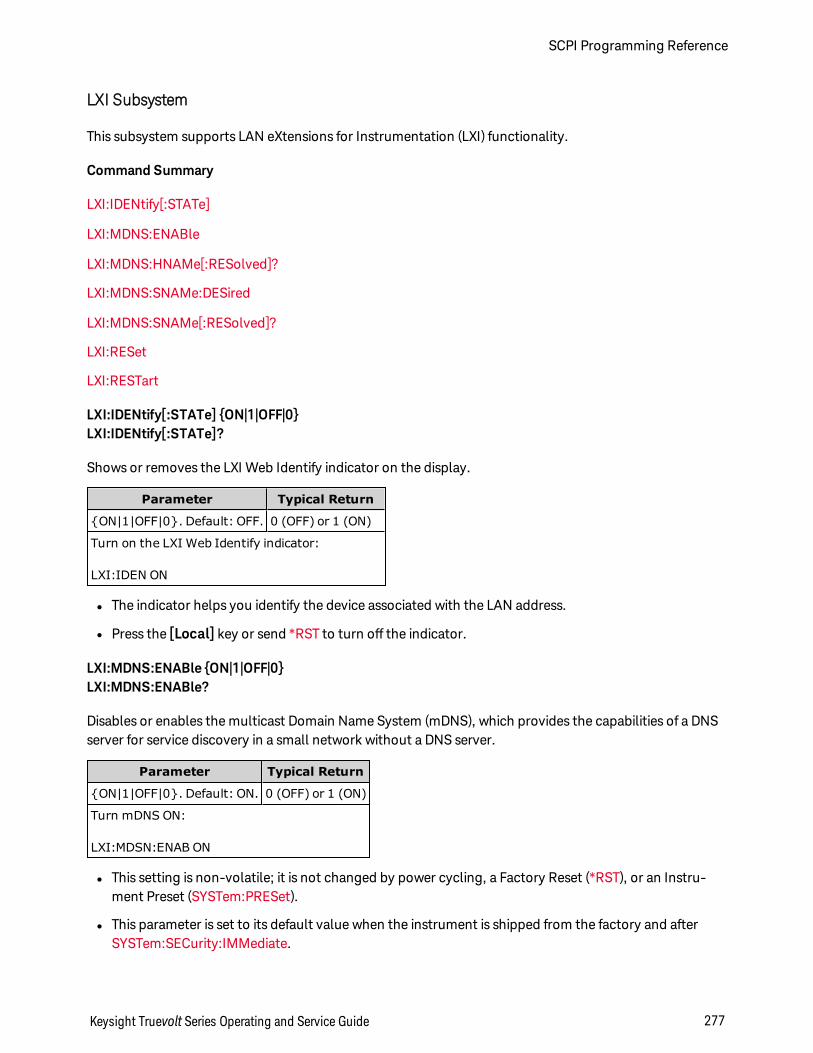
LXI Subsystem
This subsystem supports LAN eXtensions for Instrumentation (LXI) functionality.
Command Summary
LXI:IDENtify[:STATe]
LXI:MDNS:ENABle
LXI:MDNS:HNAMe[:RESolved]?
LXI:MDNS:SNAMe:DESired
LXI:MDNS:SNAMe[:RESolved]?
LXI:RESet
LXI:RESTart
LXI:IDENtify[:STATe] ON|1|OFF|0LXI:IDENtify[:STATe]?
Shows or removes the LXI Web Identify indicator on the display.
Parameter Typical Return
ON|1|OFF|0. Default: OFF. 0 (OFF) or 1 (ON)
Turn on the LXI Web Identify indicator:
LXI:IDEN ON
l The indicator helps you identify the device associated with the LAN address.
l Press the [Local] key or send *RST to turn off the indicator.
LXI:MDNS:ENABle ON|1|OFF|0LXI:MDNS:ENABle?
Disables or enables the multicast Domain Name System (mDNS), which provides the capabilities of a DNSserver for service discovery in a small network without a DNS server.
Parameter Typical Return
ON|1|OFF|0. Default: ON. 0 (OFF) or 1 (ON)
Turn mDNS ON:
LXI:MDSN:ENAB ON
l This setting is non-volatile; it is not changed by power cycling, a Factory Reset (*RST), or an Instru-ment Preset (SYSTem:PRESet).
l This parameter is set to its default value when the instrument is shipped from the factory and afterSYSTem:SECurity:IMMediate.
Keysight Truevolt Series Operating and Service Guide 277
SCPI Programming Reference
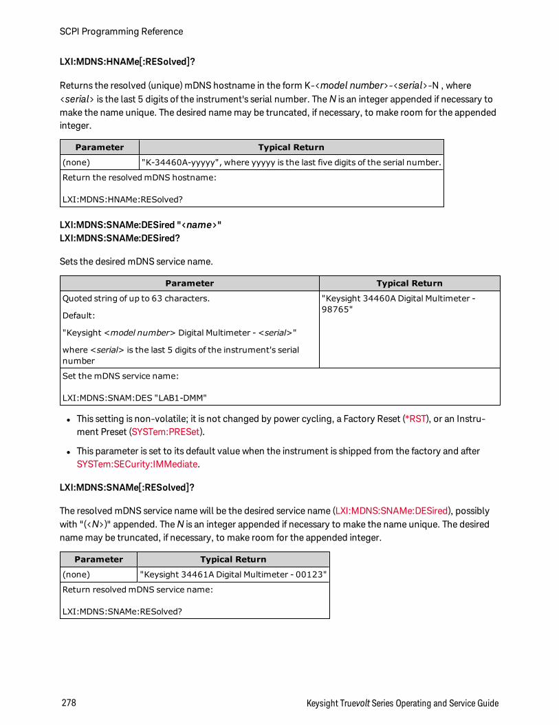
LXI:MDNS:HNAMe[:RESolved]?
Returns the resolved (unique) mDNS hostname in the form K-<model number>-<serial>-N , where<serial> is the last 5 digits of the instrument's serial number. TheN is an integer appended if necessary tomake the name unique. The desired name may be truncated, if necessary, to make room for the appendedinteger.
Parameter Typical Return
(none) "K-34460A-yyyyy", where yyyyy is the last five digits of the serial number.
Return the resolved mDNS hostname:
LXI:MDNS:HNAMe:RESolved?
LXI:MDNS:SNAMe:DESired "<name>"LXI:MDNS:SNAMe:DESired?
Sets the desired mDNS service name.
Parameter Typical Return
Quoted string of up to 63 characters.
Default:
"Keysight <model number> Digital Multimeter - <serial>"
where <serial> is the last 5 digits of the instrument's serialnumber
"Keysight 34460A Digital Multimeter -98765"
Set the mDNS service name:
LXI:MDNS:SNAM:DES "LAB1-DMM"
l This setting is non-volatile; it is not changed by power cycling, a Factory Reset (*RST), or an Instru-ment Preset (SYSTem:PRESet).
l This parameter is set to its default value when the instrument is shipped from the factory and afterSYSTem:SECurity:IMMediate.
LXI:MDNS:SNAMe[:RESolved]?
The resolved mDNS service name will be the desired service name (LXI:MDNS:SNAMe:DESired), possiblywith "(<N>)" appended. TheN is an integer appended if necessary to make the name unique. The desiredname may be truncated, if necessary, to make room for the appended integer.
Parameter Typical Return
(none) "Keysight 34461A Digital Multimeter - 00123"
Return resolved mDNS service name:
LXI:MDNS:SNAMe:RESolved?
SCPI Programming Reference
278 Keysight Truevolt Series Operating and Service Guide
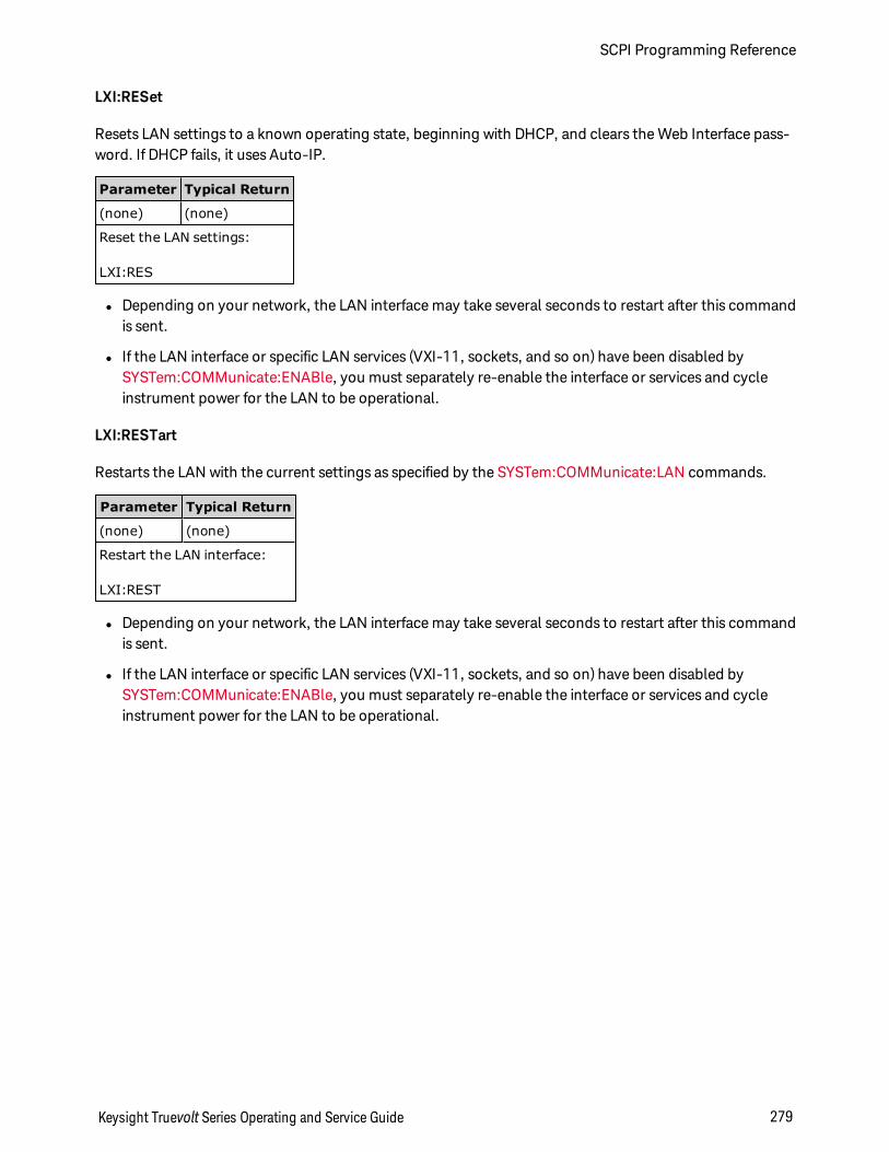
LXI:RESet
Resets LAN settings to a known operating state, beginning with DHCP, and clears the Web Interface pass-word. If DHCP fails, it uses Auto-IP.
Parameter Typical Return
(none) (none)
Reset the LAN settings:
LXI:RES
l Depending on your network, the LAN interface may take several seconds to restart after this commandis sent.
l If the LAN interface or specific LAN services (VXI-11, sockets, and so on) have been disabled bySYSTem:COMMunicate:ENABle, you must separately re-enable the interface or services and cycleinstrument power for the LAN to be operational.
LXI:RESTart
Restarts the LAN with the current settings as specified by the SYSTem:COMMunicate:LAN commands.
Parameter Typical Return
(none) (none)
Restart the LAN interface:
LXI:REST
l Depending on your network, the LAN interface may take several seconds to restart after this commandis sent.
l If the LAN interface or specific LAN services (VXI-11, sockets, and so on) have been disabled bySYSTem:COMMunicate:ENABle, you must separately re-enable the interface or services and cycleinstrument power for the LAN to be operational.
Keysight Truevolt Series Operating and Service Guide 279
SCPI Programming Reference
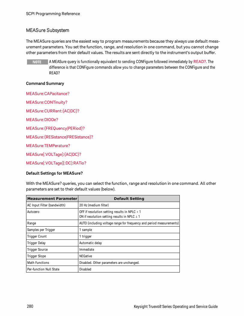
MEASure Subsystem
The MEASure queries are the easiest way to program measurements because they always use default meas-urement parameters. You set the function, range, and resolution in one command, but you cannot changeother parameters from their default values. The results are sent directly to the instrument's output buffer.
A MEASure query is functionally equivalent to sending CONFigure followed immediately by READ?. Thedifference is that CONFigure commands allow you to change parameters between the CONFigure and theREAD?
Command Summary
MEASure:CAPacitance?
MEASure:CONTinuity?
MEASure:CURRent:AC|DC?
MEASure:DIODe?
MEASure:FREQuency|PERiod?
MEASure:RESistance|FRESistance?
MEASure:TEMPerature?
MEASure[:VOLTage]:AC|DC?
MEASure[:VOLTage][:DC]:RATio?
Default Settings for MEASure?
With the MEASure? queries, you can select the function, range and resolution in one command. All otherparameters are set to their default values (below).
Measurement Parameter Default Setting
AC Input Filter (bandwidth) 20 Hz (medium filter)
Autozero OFF if resolution setting results in NPLC < 1ON if resolution setting results in NPLC ≥ 1
Range AUTO (including voltage range for frequency and period measurements)
Samples per Trigger 1 sample
Trigger Count 1 trigger
Trigger Delay Automatic delay
Trigger Source Immediate
Trigger Slope NEGative
Math Functions Disabled. Other parameters are unchanged.
Per-function Null State Disabled
SCPI Programming Reference
280 Keysight Truevolt Series Operating and Service Guide
Using the MEASure? Query
The following example configures DC voltage measurements, internally triggers the instrument to take ameasurement, and reads the measurement. The default range (autorange) and resolution (10 PLC) areused for the measurement.
MEAS:VOLT:DC?
Typical Response: +4.23450000E-03
The following example configures the instrument for 2-wire resistance measurements, triggers the instru-ment to take a measurement, and reads the measurement. The 1 kΩ range is selected with 0.1 Ω res-olution.
MEAS:RES? 1000,0.1
Typical Response: +3.27150000E+02
Keysight Truevolt Series Operating and Service Guide 281
SCPI Programming Reference
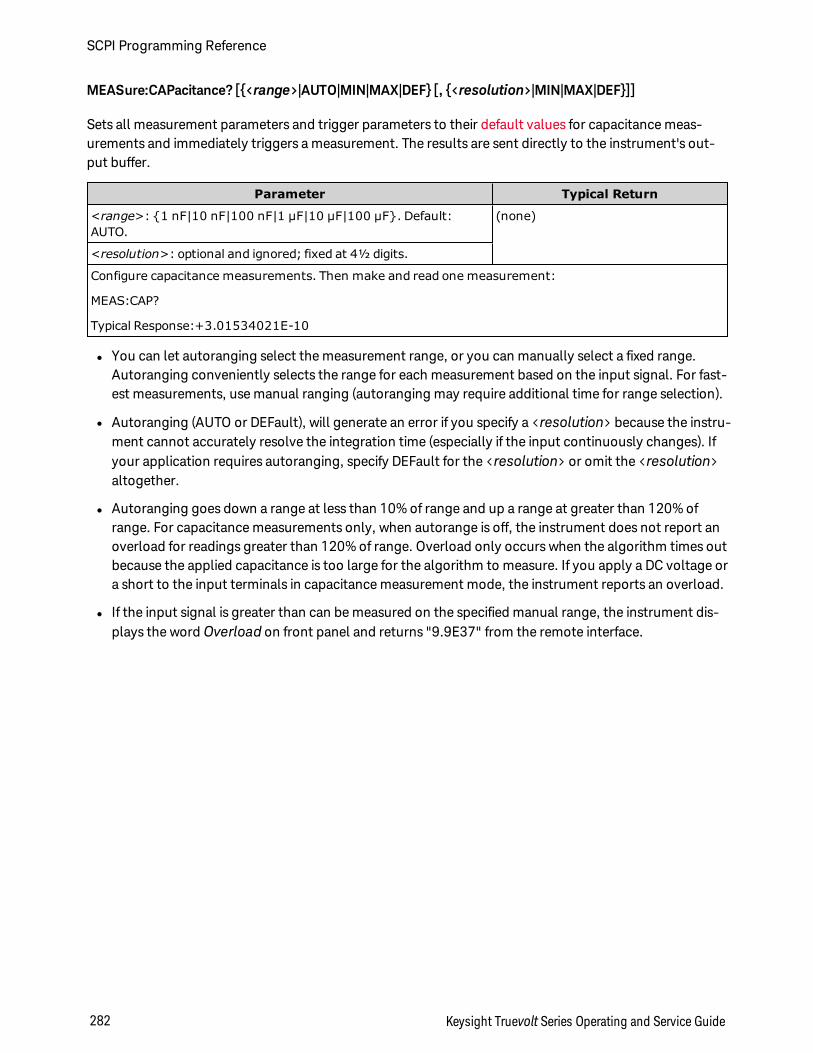
MEASure:CAPacitance? [<range>|AUTO|MIN|MAX|DEF [, <resolution>|MIN|MAX|DEF]]
Sets all measurement parameters and trigger parameters to their default values for capacitance meas-urements and immediately triggers a measurement. The results are sent directly to the instrument's out-put buffer.
Parameter Typical Return
<range>: 1 nF|10 nF|100 nF|1 µF|10 µF|100 µF. Default:AUTO.
(none)
<resolution>: optional and ignored; fixed at 4½ digits.
Configure capacitance measurements. Then make and read one measurement:
MEAS:CAP?
Typical Response:+3.01534021E-10
l You can let autoranging select the measurement range, or you can manually select a fixed range.Autoranging conveniently selects the range for each measurement based on the input signal. For fast-est measurements, use manual ranging (autoranging may require additional time for range selection).
l Autoranging (AUTO or DEFault), will generate an error if you specify a <resolution> because the instru-ment cannot accurately resolve the integration time (especially if the input continuously changes). Ifyour application requires autoranging, specify DEFault for the <resolution> or omit the <resolution>altogether.
l Autoranging goes down a range at less than 10% of range and up a range at greater than 120% ofrange. For capacitance measurements only, when autorange is off, the instrument does not report anoverload for readings greater than 120% of range. Overload only occurs when the algorithm times outbecause the applied capacitance is too large for the algorithm to measure. If you apply a DC voltage ora short to the input terminals in capacitance measurement mode, the instrument reports an overload.
l If the input signal is greater than can be measured on the specified manual range, the instrument dis-plays the word Overload on front panel and returns "9.9E37" from the remote interface.
SCPI Programming Reference
282 Keysight Truevolt Series Operating and Service Guide
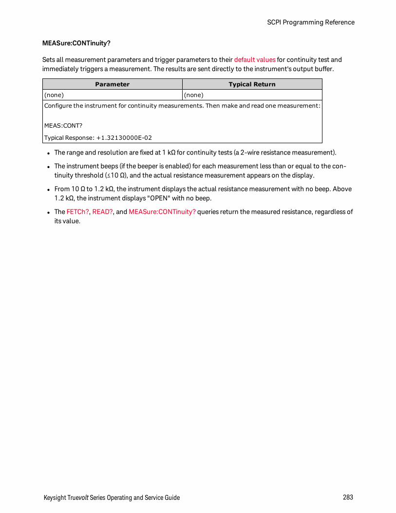
MEASure:CONTinuity?
Sets all measurement parameters and trigger parameters to their default values for continuity test andimmediately triggers a measurement. The results are sent directly to the instrument's output buffer.
Parameter Typical Return
(none) (none)
Configure the instrument for continuity measurements. Then make and read one measurement:
MEAS:CONT?
Typical Response: +1.32130000E-02
l The range and resolution are fixed at 1 kΩ for continuity tests (a 2-wire resistance measurement).
l The instrument beeps (if the beeper is enabled) for each measurement less than or equal to the con-tinuity threshold (≤10 Ω), and the actual resistance measurement appears on the display.
l From 10 Ω to 1.2 kΩ, the instrument displays the actual resistance measurement with no beep. Above1.2 kΩ, the instrument displays "OPEN" with no beep.
l The FETCh?, READ?, and MEASure:CONTinuity? queries return the measured resistance, regardless ofits value.
Keysight Truevolt Series Operating and Service Guide 283
SCPI Programming Reference
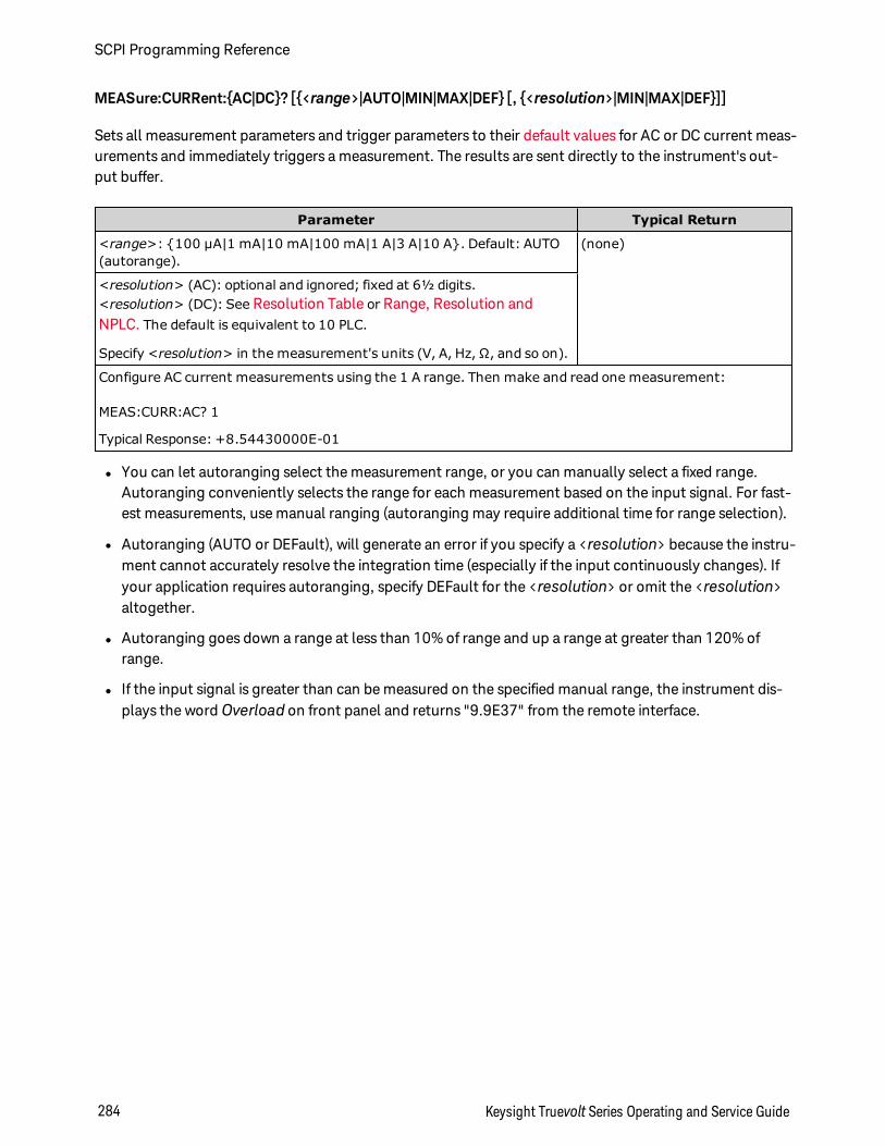
MEASure:CURRent:AC|DC? [<range>|AUTO|MIN|MAX|DEF [, <resolution>|MIN|MAX|DEF]]
Sets all measurement parameters and trigger parameters to their default values for AC or DC current meas-urements and immediately triggers a measurement. The results are sent directly to the instrument's out-put buffer.
Parameter Typical Return
<range>: 100 µA|1 mA|10 mA|100 mA|1 A|3 A|10 A. Default: AUTO(autorange).
(none)
<resolution> (AC): optional and ignored; fixed at 6½ digits.<resolution> (DC): See Resolution Table or Range, Resolution andNPLC. The default is equivalent to 10 PLC.
Specify <resolution> in the measurement's units (V, A, Hz, Ω, and so on).
Configure AC current measurements using the 1 A range. Then make and read one measurement:
MEAS:CURR:AC? 1
Typical Response: +8.54430000E-01
l You can let autoranging select the measurement range, or you can manually select a fixed range.Autoranging conveniently selects the range for each measurement based on the input signal. For fast-est measurements, use manual ranging (autoranging may require additional time for range selection).
l Autoranging (AUTO or DEFault), will generate an error if you specify a <resolution> because the instru-ment cannot accurately resolve the integration time (especially if the input continuously changes). Ifyour application requires autoranging, specify DEFault for the <resolution> or omit the <resolution>altogether.
l Autoranging goes down a range at less than 10% of range and up a range at greater than 120% ofrange.
l If the input signal is greater than can be measured on the specified manual range, the instrument dis-plays the word Overload on front panel and returns "9.9E37" from the remote interface.
SCPI Programming Reference
284 Keysight Truevolt Series Operating and Service Guide
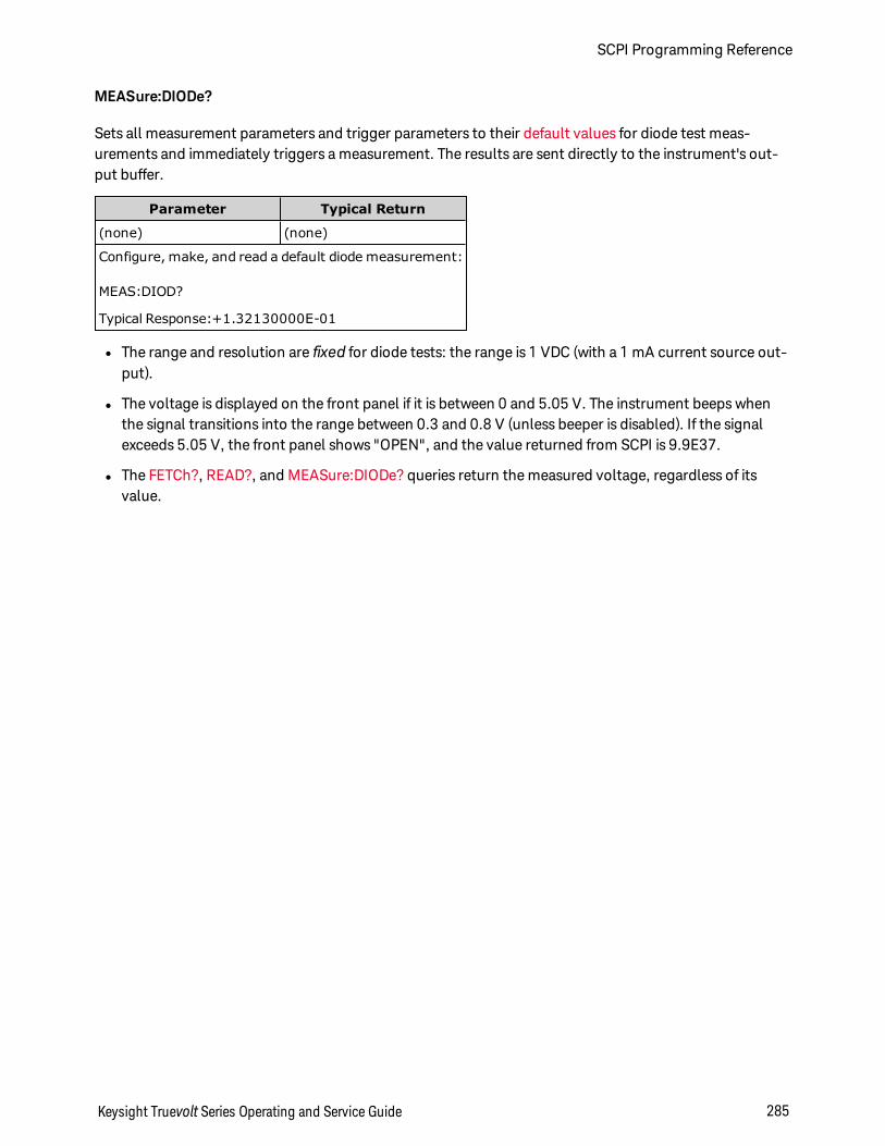
MEASure:DIODe?
Sets all measurement parameters and trigger parameters to their default values for diode test meas-urements and immediately triggers a measurement. The results are sent directly to the instrument's out-put buffer.
Parameter Typical Return
(none) (none)
Configure, make, and read a default diode measurement:
MEAS:DIOD?
Typical Response:+1.32130000E-01
l The range and resolution are fixed for diode tests: the range is 1 VDC (with a 1 mA current source out-put).
l The voltage is displayed on the front panel if it is between 0 and 5.05 V. The instrument beeps whenthe signal transitions into the range between 0.3 and 0.8 V (unless beeper is disabled). If the signalexceeds 5.05 V, the front panel shows "OPEN", and the value returned from SCPI is 9.9E37.
l The FETCh?, READ?, and MEASure:DIODe? queries return the measured voltage, regardless of itsvalue.
Keysight Truevolt Series Operating and Service Guide 285
SCPI Programming Reference
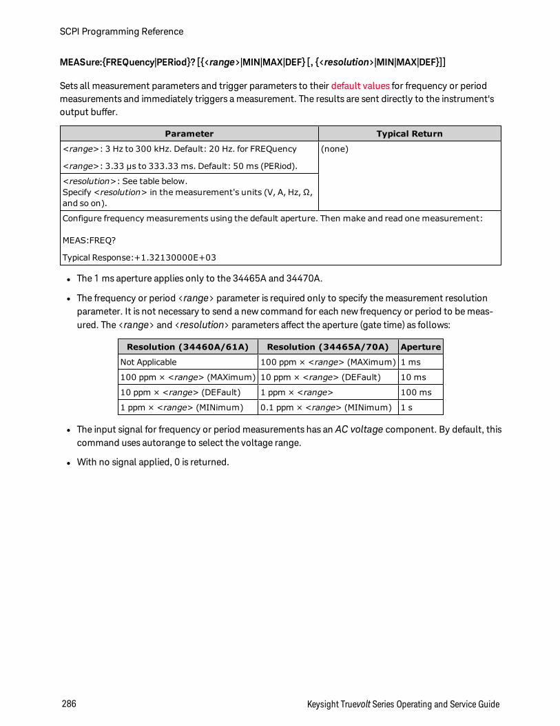
MEASure:FREQuency|PERiod? [<range>|MIN|MAX|DEF [, <resolution>|MIN|MAX|DEF]]
Sets all measurement parameters and trigger parameters to their default values for frequency or periodmeasurements and immediately triggers a measurement. The results are sent directly to the instrument'soutput buffer.
Parameter Typical Return
<range>: 3 Hz to 300 kHz. Default: 20 Hz. for FREQuency
<range>: 3.33 µs to 333.33 ms. Default: 50 ms (PERiod).
(none)
<resolution>: See table below.Specify <resolution> in the measurement's units (V, A, Hz, Ω,and so on).
Configure frequency measurements using the default aperture. Then make and read one measurement:
MEAS:FREQ?
Typical Response:+1.32130000E+03
l The 1 ms aperture applies only to the 34465A and 34470A.
l The frequency or period <range> parameter is required only to specify the measurement resolutionparameter. It is not necessary to send a new command for each new frequency or period to be meas-ured. The <range> and <resolution> parameters affect the aperture (gate time) as follows:
Resolution (34460A/61A) Resolution (34465A/70A) Aperture
Not Applicable 100 ppm × <range> (MAXimum) 1 ms
100 ppm × <range> (MAXimum) 10 ppm × <range> (DEFault) 10 ms
10 ppm × <range> (DEFault) 1 ppm × <range> 100 ms
1 ppm × <range> (MINimum) 0.1 ppm × <range> (MINimum) 1 s
l The input signal for frequency or period measurements has an AC voltage component. By default, thiscommand uses autorange to select the voltage range.
l With no signal applied, 0 is returned.
SCPI Programming Reference
286 Keysight Truevolt Series Operating and Service Guide
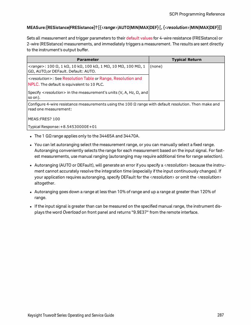
MEASure:RESistance|FRESistance? [<range>|AUTO|MIN|MAX|DEF [, <resolution>|MIN|MAX|DEF]]
Sets all measurement and trigger parameters to their default values for 4-wire resistance (FRESistance) or2-wire (RESistance) measurements, and immediately triggers a measurement. The results are sent directlyto the instrument's output buffer.
Parameter Typical Return
<range>: 100 Ω, 1 kΩ, 10 kΩ, 100 kΩ, 1 MΩ, 10 MΩ, 100 MΩ, 1GΩ, AUTO,or DEFault. Default: AUTO.
(none)
<resolution>: See Resolution Table or Range, Resolution andNPLC. The default is equivalent to 10 PLC.
Specify <resolution> in the measurement's units (V, A, Hz, Ω, andso on).
Configure 4-wire resistance measurements using the 100 Ω range with default resolution. Then make andread one measurement:
MEAS:FRES? 100
Typical Response:+8.54530000E+01
l The 1 GΩ range applies only to the 34465A and 34470A.
l You can let autoranging select the measurement range, or you can manually select a fixed range.Autoranging conveniently selects the range for each measurement based on the input signal. For fast-est measurements, use manual ranging (autoranging may require additional time for range selection).
l Autoranging (AUTO or DEFault), will generate an error if you specify a <resolution> because the instru-ment cannot accurately resolve the integration time (especially if the input continuously changes). Ifyour application requires autoranging, specify DEFault for the <resolution> or omit the <resolution>altogether.
l Autoranging goes down a range at less than 10% of range and up a range at greater than 120% ofrange.
l If the input signal is greater than can be measured on the specified manual range, the instrument dis-plays the word Overload on front panel and returns "9.9E37" from the remote interface.
Keysight Truevolt Series Operating and Service Guide 287
SCPI Programming Reference
MEASure:TEMPerature? [FRTD|RTD|FTHermistor|THERmistor|TCouple|DEFault [, <type>|DEFault [,1[, <resolution>|MIN|MAX|DEF]]]]
Sets all measurement parameters and trigger parameters to their default values for temperature meas-urements and immediately triggers a measurement. The results are sent directly to the instrument's out-put buffer.
Parameter Typical Return
<probe_type>: FRTD|RTD|FTHermistor|THERmistor|TCouple. Default: FRTD. (none)
<type>: 85 (only possible value for RTD/FRTD), 5000 (only possible value for THERmis-tor/FTHermistor), or E, J, K, N, R, T (TCouple).
<resolution>: See Resolution Table or Range, Resolution and NPLC. Thedefault is equivalent to 10 PLC.
Configure a 4-wire RTD measurement with default resolution. Then make and read one measurement:
MEAS:TEMP? FRTD,85
Typical Response:+2.12320000E+01
l Thermocouple measurements (TC) apply only to the 34465A and 34470A.
l For temperature measurements, the instrument internally selects the range; you cannot select therange to be used. The range ("1" is the only allowed value) is used only in conjunction with resolutionto determine NPLC.
l The <resolution>parameter only determines the integration time; it does not specify the resolution ofthe temperature measurement. This parameter is optional; however, if you specify <resolution>, youmust also specify "1" as the implied range parameter. For example: CONF:TEMPRTD,85,1,0.000001 selects the 10 PLC integration time on the 34461A.
l To change temperature units, use UNIT:TEMPerature.
l For RTD and thermistor measurements, the instrument autoranges to the correct range for the trans-ducer resistance measurement. For thermocouple measurements, the 100 mV range is selected.
l For thermocouple measurements, the internal reference is selected. See SENSe:TEMPer-ature:TCouple:RJUNction:TYPE.
l If the input signal is greater than can be measured on the specified manual range, the instrument dis-plays the word Overload on front panel and returns "9.9E37" from the remote interface.
SCPI Programming Reference
288 Keysight Truevolt Series Operating and Service Guide
MEASure[:VOLTage]:AC|DC? [<range>|AUTO|MIN|MAX|DEF [, <resolution>|MIN|MAX|DEF]]
Sets all measurement parameters and trigger parameters to their default values for AC or DC voltage meas-urements and immediately triggers a measurement. The results are sent directly to the instrument's out-put buffer.
The maximum range parameter (MAX) is 1000 V. However, the SAFETY LIMIT on the frontand rear HI/LO input terminals is 750 VAC (rms). The rms voltage is waveform dependent.A sine wave is limited to 750 VAC (rms), but a 1000 Vpk square wave is safe. Connectionto AC mains power is further limited to CAT II (300 V). SeeSafety and RegulatoryInformation for more information on the safety features and the safe operation of thisinstrument.
Parameter Typical Return
<range>: 100 mV, 1 V, 10 V, 100 V, 1000 V, AUTO (default) or DEFault (none)
<resolution> (AC): optional and ignored; fixed at 6½ digits.
<resolution> (DC): See Resolution Table or Range, Resolution andNPLC. The default is equivalent to 10 PLC.
Specify <resolution> in the measurement's units (V, A, Hz, Ω, and so on).
Configure DC voltage measurements using the 10 V range with 1 mV resolution.Then make and read onemeasurement:
MEAS:VOLT:DC? 10,0.001
Typical Response:+8.54530000E+01
l You can let autoranging select the measurement range, or you can manually select a fixed range.Autoranging conveniently selects the range for each measurement based on the input signal. For fast-est measurements, use manual ranging (autoranging may require additional time for range selection).
l Autoranging (AUTO or DEFault), will generate an error if you specify a <resolution> because the instru-ment cannot accurately resolve the integration time (especially if the input continuously changes). Ifyour application requires autoranging, specify DEFault for the <resolution> or omit the <resolution>altogether.
l Autoranging goes down a range at less than 10% of range and up a range at greater than 120% ofrange.
l If the input signal is greater than can be measured on the specified manual range, the instrument dis-plays the word Overload on front panel and returns "9.9E37" from the remote interface.
Keysight Truevolt Series Operating and Service Guide 289
SCPI Programming Reference
MEASure[:VOLTage][:DC]:RATio? [<range>|AUTO|MIN|MAX|DEF [, <resolution>|MIN|MAX|DEF]]
Sets all measurement parameters and trigger parameters to their default values for DC voltage ratio meas-urements and immediately triggers a measurement. The results are sent directly to the instrument's out-put buffer.
To calculate a ratio, the instrument measures a DC reference voltage applied to the Sense terminal andthe DC signal voltage applied to the Input terminals. It then uses the formula:
Ratio = DC signal voltage / DC reference voltage
Parameter Typical Return
<range>: 100 mV, 1 V, 10 V, 100 V, 1000 V, AUTO (default) or DEFault (none)
<resolution>: See Resolution Table or Range, Resolution andNPLC. The default is equivalent to 10 PLC.
Configure DC voltage ratio measurements using the 100 V range with 1 mV resolution. Then make and readone measurement:
MEAS:VOLT:DC:RAT? 100,0.001
Typical Response:+4.27150000E+00
l The Sense terminals have a maximum measurable input of ±12 VDC. Autoranging is automaticallyselected for reference voltage measurements on the Sense terminals.
l The Input LO and Sense LO terminals must have a common reference and cannot have a voltage dif-ference greater than ±2 V.
l The specified measurement range applies only to the signal connected to the Input terminals. The sig-nal on the Input terminals can be any DC voltage up to 1,000 V.
l For the Input terminals, you can allow the instrument to select the measurement range by autor-anging or you can select a fixed range using manual ranging. Autoranging decides which range to usefor each measurement based on the input signal. For faster measurements, use manual ranging oneach measurement (additional time is required for autoranging to select a range).
l Autoranging (AUTO or DEFault), will generate an error if you specify a <resolution> because the instru-ment cannot accurately resolve the integration time (especially if the input continuously changes). Ifyour application requires autoranging, specify DEFault for the <resolution> or omit the <resolution>altogether.
l Autoranging goes down a range at less than 10% of range and up a range at greater than 120% ofrange.
l If the input signal is greater than can be measured on the specified manual range, the instrument dis-plays the word Overload on front panel and returns "9.9E37" from the remote interface.
SCPI Programming Reference
290 Keysight Truevolt Series Operating and Service Guide
MMEMory Subsystem - General Purpose File Management
The MMEMory subsystem's general purpose file management commands are listed below. The MMEMorysubsystem also includes two other types of commands:
STATe and PREFerence File Management
Data Transfer
Commands and Queries
MMEMory:CATalog[:ALL]?
MMEMory:CDIRectory
MMEMory:COPY
MMEMory:DELete
MMEMory:MDIRectory
MMEMory:MOVE
MMEMory:RDIRectory
Keysight Truevolt Series Operating and Service Guide 291
SCPI Programming Reference

Folder and file formats
Many MMEMory commands refer to folders and files. These have specific structures, described below.
Format for a <folder>
l The format for <folder> is "[[<drive>:]<path>]", where <drive> can be INTernal or USB, and <path> isa folder path, and <filespec> specifies a subset of files.
l INTernal specifies the internal flash file system. USB specifies a front panel USB storage device.
l If <drive> is specified, <path> is interpreted as an absolute folder path. Absolute paths begin with "\"or "/" and start at the root folder of <drive>.
l If <drive> is omitted, <path> is relative to the folder specified by MMEMory:CDIRectory. Relativepaths must NOT begin with \ or /.
l Folder and file names cannot contain the following characters: \ / : * ? " < > |
l The <folder> parameter cannot exceed 240 characters.
l The specified folder must exist and cannot be marked as hidden or system. The exception isMMEMory:MDIRectory, which creates a folder. For MMEMory:MDIRectory, all folder levels above thenew one must exist.
Format for a <file>
l The format for a file name is "[[<drive>:]<path>]<file_name>", where <drive> can be INTernal or USB,and <path>is a folder path.
l INTernal specifies the internal flash file system. USB specifies a front panel USB storage device.
l If <drive> is specified, <path> is interpreted as an absolute folder path. Absolute paths begin with "\"or "/" and start at the root folder of <drive>.
l If <drive> is omitted, <path> is relative to the folder specified by MMEMory:CDIRectory. Relativepaths must NOT begin with \ or /.
l Folder and file names cannot contain the following characters: \ / : * ? " < > |
l The combination of folder and file name cannot exceed 240 characters.
SCPI Programming Reference
292 Keysight Truevolt Series Operating and Service Guide

MMEMory:CATalog[:ALL]? [<folder>[<filespec>]]
Returns a list of files in the specified folder.
Parameter Typical Return
Any valid folder name; defaults to folder selectedby MMEMory:CDIRectory
+1000000000,+327168572,"command.exe,,375808","MyDCVMeas.sta,STAT,8192",MyData.csv,ASC,11265"
List all files in the folder MyData on the front panel USB storage device:
MMEM:CAT? "USB:\MyData"
List all state files in the root directory of internal memory:
MMEM:CAT? "INT:\*.sta"
l If <filespec> is omitted or is *.*, the command or query acts on all files. You can also use the * as a gen-eric wildcard: *.sta, abc*.*, and so on.
l The catalog takes the following form:
<mem_used>,<mem_free>,"<file listing>"
The instrument returns two numbers and a string for each file in the folder. The first number is the num-ber of bytes used on the drive. The second indicates the number of bytes available. Each <file listing>is in the format "<file_name>,<file_type>,<file_size>" (including the quotation marks), where <file_name> is the name of the file including file extension, if any; <file_type> is either STAT for STATe (.sta)files, ASC for DATA (.csv) files, PREF for PREFerence (.prf) files, FOLD for folders, or null for all other fileextensions; <file_size> is the file size in bytes.
l If no files exist, only <mem_used>,<mem_free> is returned.
l Because the instrument uses a small amount of space in the flash file system for internal use, the<mem_used> value is never zero.
Keysight Truevolt Series Operating and Service Guide 293
SCPI Programming Reference
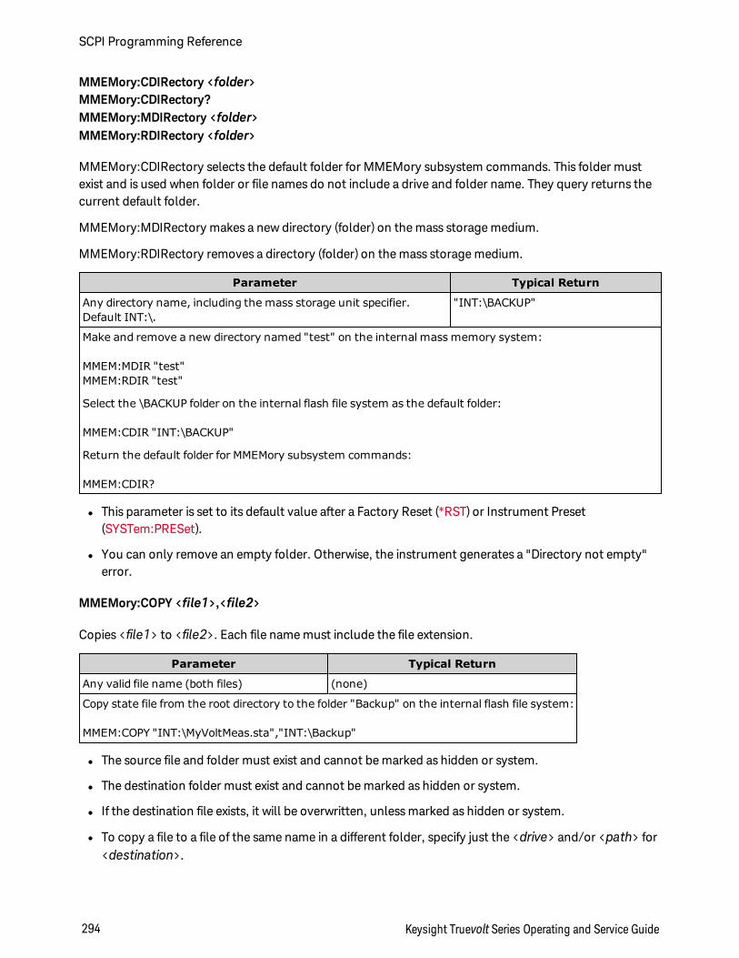
MMEMory:CDIRectory <folder>MMEMory:CDIRectory?MMEMory:MDIRectory <folder>MMEMory:RDIRectory <folder>
MMEMory:CDIRectory selects the default folder for MMEMory subsystem commands. This folder mustexist and is used when folder or file names do not include a drive and folder name. They query returns thecurrent default folder.
MMEMory:MDIRectory makes a new directory (folder) on the mass storage medium.
MMEMory:RDIRectory removes a directory (folder) on the mass storage medium.
Parameter Typical Return
Any directory name, including the mass storage unit specifier.Default INT:\.
"INT:\BACKUP"
Make and remove a new directory named "test" on the internal mass memory system:
MMEM:MDIR "test"MMEM:RDIR "test"
Select the \BACKUP folder on the internal flash file system as the default folder:
MMEM:CDIR "INT:\BACKUP"
Return the default folder for MMEMory subsystem commands:
MMEM:CDIR?
l This parameter is set to its default value after a Factory Reset (*RST) or Instrument Preset(SYSTem:PRESet).
l You can only remove an empty folder. Otherwise, the instrument generates a "Directory not empty"error.
MMEMory:COPY <file1>,<file2>
Copies <file1> to <file2>. Each file name must include the file extension.
Parameter Typical Return
Any valid file name (both files) (none)
Copy state file from the root directory to the folder "Backup" on the internal flash file system:
MMEM:COPY "INT:\MyVoltMeas.sta","INT:\Backup"
l The source file and folder must exist and cannot be marked as hidden or system.
l The destination folder must exist and cannot be marked as hidden or system.
l If the destination file exists, it will be overwritten, unless marked as hidden or system.
l To copy a file to a file of the same name in a different folder, specify just the <drive> and/or <path> for<destination>.
SCPI Programming Reference
294 Keysight Truevolt Series Operating and Service Guide
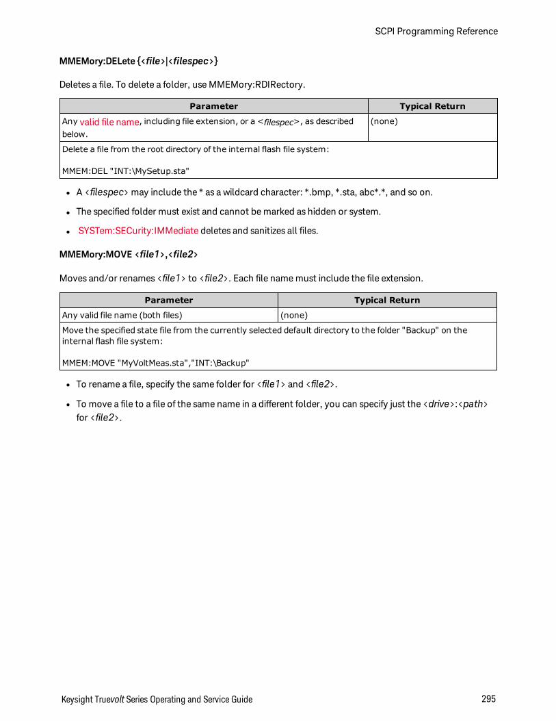
MMEMory:DELete <file>|<filespec>
Deletes a file. To delete a folder, use MMEMory:RDIRectory.
Parameter Typical Return
Any valid file name, including file extension, or a <filespec>, as describedbelow.
(none)
Delete a file from the root directory of the internal flash file system:
MMEM:DEL "INT:\MySetup.sta"
l A <filespec> may include the * as a wildcard character: *.bmp, *.sta, abc*.*, and so on.
l The specified folder must exist and cannot be marked as hidden or system.
l SYSTem:SECurity:IMMediate deletes and sanitizes all files.
MMEMory:MOVE <file1>,<file2>
Moves and/or renames <file1> to <file2>. Each file name must include the file extension.
Parameter Typical Return
Any valid file name (both files) (none)
Move the specified state file from the currently selected default directory to the folder "Backup" on theinternal flash file system:
MMEM:MOVE "MyVoltMeas.sta","INT:\Backup"
l To rename a file, specify the same folder for <file1> and <file2>.
l To move a file to a file of the same name in a different folder, you can specify just the <drive>:<path>for <file2>.
Keysight Truevolt Series Operating and Service Guide 295
SCPI Programming Reference
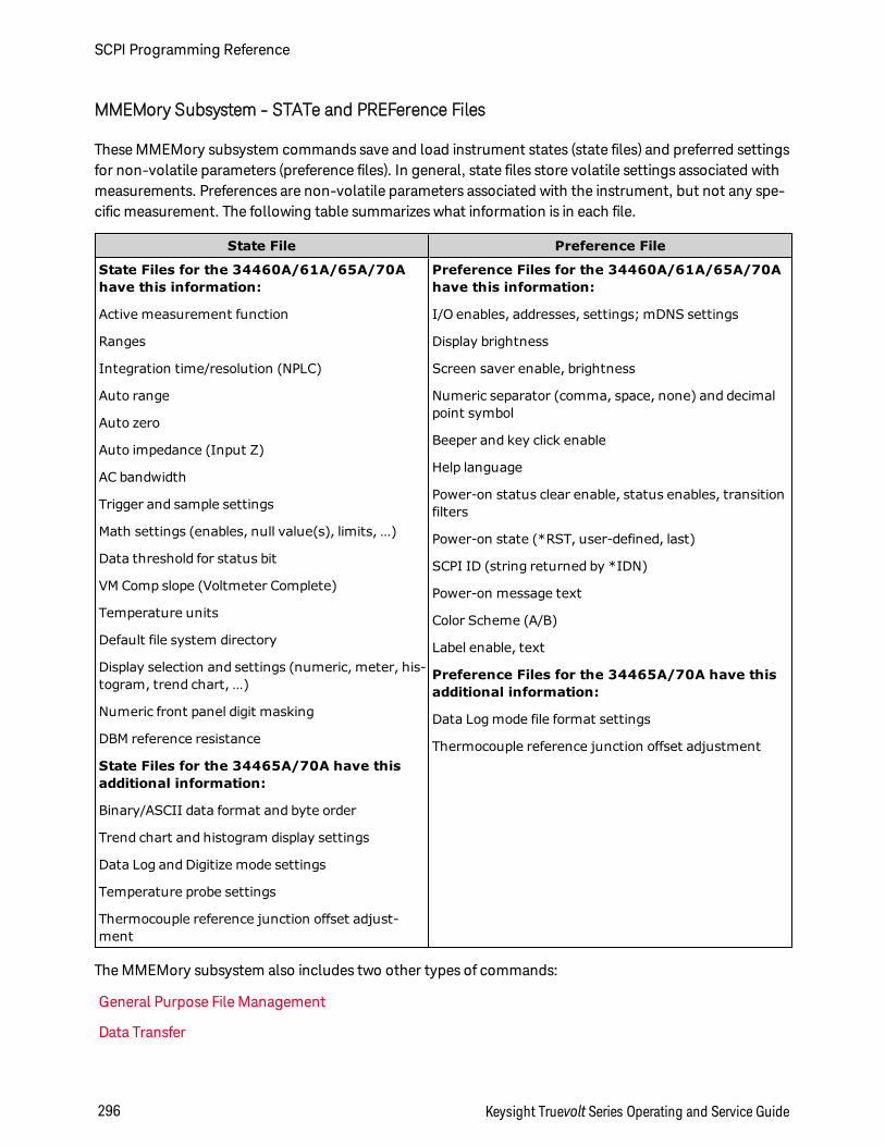
MMEMory Subsystem - STATe and PREFerence Files
These MMEMory subsystem commands save and load instrument states (state files) and preferred settingsfor non-volatile parameters (preference files). In general, state files store volatile settings associated withmeasurements. Preferences are non-volatile parameters associated with the instrument, but not any spe-cific measurement. The following table summarizes what information is in each file.
State File Preference File
State Files for the 34460A/61A/65A/70Ahave this information:
Active measurement function
Ranges
Integration time/resolution (NPLC)
Auto range
Auto zero
Auto impedance (Input Z)
AC bandwidth
Trigger and sample settings
Math settings (enables, null value(s), limits, …)
Data threshold for status bit
VM Comp slope (Voltmeter Complete)
Temperature units
Default file system directory
Display selection and settings (numeric, meter, his-togram, trend chart, …)
Numeric front panel digit masking
DBM reference resistance
State Files for the 34465A/70A have thisadditional information:
Binary/ASCII data format and byte order
Trend chart and histogram display settings
Data Log and Digitize mode settings
Temperature probe settings
Thermocouple reference junction offset adjust-ment
Preference Files for the 34460A/61A/65A/70Ahave this information:
I/O enables, addresses, settings; mDNS settings
Display brightness
Screen saver enable, brightness
Numeric separator (comma, space, none) and decimalpoint symbol
Beeper and key click enable
Help language
Power-on status clear enable, status enables, transitionfilters
Power-on state (*RST, user-defined, last)
SCPI ID (string returned by *IDN)
Power-on message text
Color Scheme (A/B)
Label enable, text
Preference Files for the 34465A/70A have thisadditional information:
Data Log mode file format settings
Thermocouple reference junction offset adjustment
The MMEMory subsystem also includes two other types of commands:
General Purpose File Management
Data Transfer
SCPI Programming Reference
296 Keysight Truevolt Series Operating and Service Guide
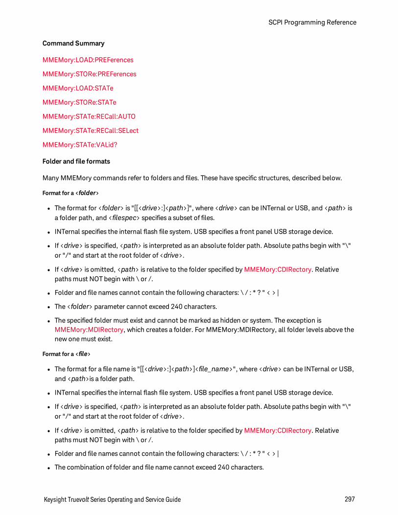
Command Summary
MMEMory:LOAD:PREFerences
MMEMory:STORe:PREFerences
MMEMory:LOAD:STATe
MMEMory:STORe:STATe
MMEMory:STATe:RECall:AUTO
MMEMory:STATe:RECall:SELect
MMEMory:STATe:VALid?
Folder and file formats
Many MMEMory commands refer to folders and files. These have specific structures, described below.
Format for a <folder>
l The format for <folder> is "[[<drive>:]<path>]", where <drive> can be INTernal or USB, and <path> isa folder path, and <filespec> specifies a subset of files.
l INTernal specifies the internal flash file system. USB specifies a front panel USB storage device.
l If <drive> is specified, <path> is interpreted as an absolute folder path. Absolute paths begin with "\"or "/" and start at the root folder of <drive>.
l If <drive> is omitted, <path> is relative to the folder specified by MMEMory:CDIRectory. Relativepaths must NOT begin with \ or /.
l Folder and file names cannot contain the following characters: \ / : * ? " < > |
l The <folder> parameter cannot exceed 240 characters.
l The specified folder must exist and cannot be marked as hidden or system. The exception isMMEMory:MDIRectory, which creates a folder. For MMEMory:MDIRectory, all folder levels above thenew one must exist.
Format for a <file>
l The format for a file name is "[[<drive>:]<path>]<file_name>", where <drive> can be INTernal or USB,and <path>is a folder path.
l INTernal specifies the internal flash file system. USB specifies a front panel USB storage device.
l If <drive> is specified, <path> is interpreted as an absolute folder path. Absolute paths begin with "\"or "/" and start at the root folder of <drive>.
l If <drive> is omitted, <path> is relative to the folder specified by MMEMory:CDIRectory. Relativepaths must NOT begin with \ or /.
l Folder and file names cannot contain the following characters: \ / : * ? " < > |
l The combination of folder and file name cannot exceed 240 characters.
Keysight Truevolt Series Operating and Service Guide 297
SCPI Programming Reference
Mass Memory (MMEMory) and State Storage
States saved by the front panel can be accessed from remote, and vice versa. For example, configure theinstrument as desired and insert a USB drive into the front panel. Then enter the following commands. Ifyou do not have a USB drive change "USB:\" to "INT:\" to use the instrument's internal flash drive instead.
MMEMory:CDIRectory "USB:\"MMEMory:MDIRectory "States"MMEMory:STORe:STATE "USB:\States\State1"
To return to this state at any time:
MMEMory:LOAD:STATE "USB:\States\State1"
You can also recall a state file from the front panel by pressing [Utility] > Store/Recall.
MMEMory:LOAD:PREFerences <file>MMEMory:STORe:PREFerences <file>
LOAD: Reboots the instrument and loads the nonvolatile I/O settings and user preferences from a file. Thespecified file cannot be empty or marked as hidden or system.STORE: Stores nonvolatile I/O settings and user preferences to a file. If the destination file exists, it will beoverwritten, unless marked as hidden or system.
When loading a preferences file that specifies a static IP address, be careful that this does not result in twoinstruments with the same IP address on your LAN. This could cause LAN configuration errors on bothinstruments.
Parameter Typical Return
Any valid file nameThe .prf file extension is optional. If you do not include this extension, the instru-ment firmware will automatically append it.
(none)
Stores the current nonvolatile I/O settings and user preferences into the specified file:
MMEM:STOR:PREF "INT:\MyPreferences"
Load nonvolatile I/O settings and user preferences from the specified file:
MMEM:LOAD:PREF "INT:\MyPreferences"
l See the State File/Preferences File table for a listing of the information contained in each file.
l The specified folder must exist and cannot be marked as hidden or system.
SCPI Programming Reference
298 Keysight Truevolt Series Operating and Service Guide
MMEMory:LOAD:STATe <filename>MMEMory:STORe:STATe <filename>
Loads an instrument state from a state file or saves the current instrument state to a state file. The filename optionally includes the folder name and the .sta file extension. If you do not include this extension,the instrument firmware will automatically append it.
Parameter Typical Return
Any valid file name (none)
Store the current instrument state to the specified state file in the root directory of the internal flash file sys-tem:
MMEM:STOR:STAT "INT:\MySetup"
Load the instrument state from MySetup.sta saved by the previous command:
MMEM:LOAD:STAT "INT:\MySetup.sta"
l See the State File/Preferences File table for a listing of the information contained in each file.
l The specified folder must exist and cannot be marked as hidden or system.
l The specified file cannot be empty or marked as hidden or system.
l The state file created by *SAV 0, called STATE_0.sta, resides in the root folder of the internal flash filesystem. It is overwritten with the power-down state of the instrument when power is cycled.
MMEMory:STATe:RECall:AUTO ON|1|OFF|0MMEMory:STATe:RECall:AUTO?
Disables or enables the automatic recall of a specific stored instrument state at power-on. Specify ON toautomatically recall the power-down state file (STATE_0 in the root folder of the internal flash file system)or a user-specified state file (MMEMory:STATe:RECall:SELect). Select "OFF" to issue a Factory Reset (*RST)at power-on.
Parameter Typical Return
ON|1|OFF|0. Default: ON. 0 (OFF) or 1 (ON)
Select the power-down state to be used at power-on.MMEM:STAT:REC:SEL "INT:\STATE_0"MMEM:STAT:REC:AUTO ON
Save the current state into a file in the root directory of the internal flash file system and load it at power-on:MMEM:STOR:STAT "INT:\MyVoltMeas"MMEM:STAT:REC:SEL "INT:\MyVoltMeas"MMEM:STAT:REC:AUTO ON
l When shipped from the factory, the instrument is configured to automatically recall the power-downstate file when power is restored.
l This setting is non-volatile; it is not changed by power cycling, a Factory Reset (*RST), or an Instru-ment Preset (SYSTem:PRESet).
Keysight Truevolt Series Operating and Service Guide 299
SCPI Programming Reference
MMEMory:STATe:RECall:SELect <file>MMEMory:STATe:RECall:SELect?
Selects which instrument state to use at power-on if the automatic recall mode is enabled(MMEMory:STATe:RECall:AUTO ON). If the automatic recall mode is disabled(MMEMory:STATe:RECall:AUTO OFF), a Factory Reset (*RST) is issued at power-on.
Parameter Typical Return
Any valid file name "INT:\MyVoltMeas"
Select the power-down state to be used at power-on.MMEM:STAT:REC:SEL "INT:\STATE_0"MMEM:STAT:REC:AUTO ON
Save the current state into a file in the root directory of the internal flash file system and load it at power-on:MMEM:STOR:STAT "INT:\MyVoltMeas"MMEM:STAT:REC:SEL "INT:\MyVoltMeas"MMEM:STAT:REC:AUTO ON
l The specified folder must exist and cannot be marked as hidden or system.
l The state file created by *SAV 0, called STATE_0.sta, resides in the root folder of the internal flash filesystem. It is overwritten with the power-down state of the instrument when power is cycled.
l When shipped from the factory, the instrument is configured to automatically recall the power-downstate file when power is restored.
l This setting is non-volatile; it is not changed by power cycling, a Factory Reset (*RST), or an Instru-ment Preset (SYSTem:PRESet).
MMEMory:STATe:VALid? <file>
Returns 1 if the specified state file exists and contains a valid state file. Returns 0 otherwise.
Parameter Typical Return
Any valid file name 1
Return the status of MyState.sta in the root folder of the internal flash file system.
MMEM:STAT:VAL? "INT:\MyState.sta"
l The specified folder must exist and cannot be marked as hidden or system.
l The specified file cannot be empty or marked as hidden or system.
l Use this query before sending *RCL or MMEMory:LOAD:STATe to determine whether a state has beenstored in the file.
SCPI Programming Reference
300 Keysight Truevolt Series Operating and Service Guide
MMEMory Subsystem - Data Transfer Commands
These commands transfer files into and out of the instrument's mass memory.
The MMEMory subsystem also includes two other types of commands:
General Purpose File Management
STATe and PREFerence File Management
Command Summary
MMEMory:DOWNload:DATA
MMEMory:DOWNload:FNAMe
MMEMory:FORMat:READing:CSEParator
MMEMory:FORMat:READing:INFormation
MMEMory:FORMat:READing:RLIMit
MMEMory:STORe:DATA
MMEMory:UPLoad?
Keysight Truevolt Series Operating and Service Guide 301
SCPI Programming Reference
Folder and file formats
Many MMEMory commands refer to folders and files. These have specific structures, described below.
Format for a <folder>
l The format for <folder> is "[[<drive>:]<path>]", where <drive> can be INTernal or USB, and <path> isa folder path, and <filespec> specifies a subset of files.
l INTernal specifies the internal flash file system. USB specifies a front panel USB storage device.
l If <drive> is specified, <path> is interpreted as an absolute folder path. Absolute paths begin with "\"or "/" and start at the root folder of <drive>.
l If <drive> is omitted, <path> is relative to the folder specified by MMEMory:CDIRectory. Relativepaths must NOT begin with \ or /.
l Folder and file names cannot contain the following characters: \ / : * ? " < > |
l The <folder> parameter cannot exceed 240 characters.
l The specified folder must exist and cannot be marked as hidden or system. The exception isMMEMory:MDIRectory, which creates a folder. For MMEMory:MDIRectory, all folder levels above thenew one must exist.
Format for a <file>
l The format for a file name is "[[<drive>:]<path>]<file_name>", where <drive> can be INTernal or USB,and <path>is a folder path.
l INTernal specifies the internal flash file system. USB specifies a front panel USB storage device.
l If <drive> is specified, <path> is interpreted as an absolute folder path. Absolute paths begin with "\"or "/" and start at the root folder of <drive>.
l If <drive> is omitted, <path> is relative to the folder specified by MMEMory:CDIRectory. Relativepaths must NOT begin with \ or /.
l Folder and file names cannot contain the following characters: \ / : * ? " < > |
l The combination of folder and file name cannot exceed 240 characters.
SCPI Programming Reference
302 Keysight Truevolt Series Operating and Service Guide
MMEMory:DOWNload:DATA <binary_block>
Downloads data from the host computer to a file whose name has been specified by MMEMory:DOWN-load:FNAMe.
The data in <binary_block> is written to the selected file.
Any data previously stored in the file is lost when you execute this command.
Parameter Typical Return
Any IEEE-488.2 definite- or indefinite-length block (none)
Write "Hello" to the file "\Myfile" on internal storage.
MMEM:DOWN:FNAM "INT:\Myfile"MMEM:DOWN:DATA #15Hello
MMEMory:DOWNload:FNAMe <filename>MMEMory:DOWNload:FNAMe?
Creates or opens the specified filename prior to writing data to that file with MMEMory:DOWNload:DATA.
Parameter Typical Return
Any valid file name (none)
Write "Hello" to the file "\Myfile" on internal storage.
MMEM:DOWN:FNAM "INT:\Myfile"MMEM:DOWN:DATA #15Hello
l The specified folder must exist and cannot be marked as hidden or system.
l If the destination file exists, it will be overwritten, unless marked as hidden or system.
l The file is created if it does not already exist.
MMEMory:FORMat:READing:CSEParator COMMa|SEMicolon|TABMMEMory:FORMat:READing:CSEParator?
Specifies the character used to separate the columns in stored data.
Parameter Typical Return
COMMa|SEMicolon|TAB. Default: COMMa. TAB, COMM or SEM
Specify tabs as the column separator:
MMEMory:FORMat:READing:CSEParator TAB
l Applies only to the 34465A and 34470A.
l Affects the format for the .csv file created by the MMEMory:STORe:DATA command, or by the datalogging/digitizing features in the 34465A/34470A.
Keysight Truevolt Series Operating and Service Guide 303
SCPI Programming Reference
MMEMory:FORMat:READing:INFormation OFF|ONMMEMory:FORMat:READing:INFormation?
Disables/enables header information and reading numbers in stored data.
Parameter Typical Return
OFF|ON. Default OFF. OFF or ON
Enable the format for the .csv file:
MMEM:FORMat:READing:INFormation ON
l Applies only to the 34465A and 34470A.
l The format for the .csv file (MMEMory:STORe:DATA ), or by the data logging/digitizing features in the34465A/34470A, are affected as follows:OFF = one reading per row, no other header or reading information.ON = enables a file header and reading numbers. The file header contains the start date and start timeof the first reading and, if the sample source is timer (SAMPle:SOURce:TIMer), the sample interval.Each data row includes a reading number and the reading.
l Affects the .dat (binary) file created by MMEMory:STORe:DATA as follows:OFF = one reading per row, no other header or per reading information.ON = one time stamp row consisting of eight 16-bit integers for: year, month, day of week, day, hour,minute, and milliseconds. 32-bit integer reading number and 64-bit IEEE-754 reading.
MMEMory:FORMat:READing:RLIMit OFF|ONMMEMory:FORMat:READing:RLIMit?
When enabled, limits the maximum number rows per stored .csv data file to one million, including anyheader row, if enabled.
Parameter Typical Return
OFF|ON. Default ON. OFF or ON
Disable row limits for the .csv file:
MMEM:FORM:READ:RLIMit OFF
l Applies only to the 34465A and 34470A.
l Affects the format for the .csv file created by the MMEMory:STORe:DATA command, or by the datalogging/digitizing features in the 34465A/34470A.
l This feature enables you to accommodate common spreadsheet, database and data analysis pro-grams that have limitations of 1 million rows per file.
l ON - Readings are stored in files named dat00001.csv, dat00002.csv, dat00003.csv ...
l OFF - Readings are is stored in a single file named dat00001.csv. The file size is limited to 232 =4.294967296 GBytes (the maximum allowed by the FAT32 file system).
SCPI Programming Reference
304 Keysight Truevolt Series Operating and Service Guide
MMEMory:STORe:DATA RDG_STORE, <file>
Stores all measurements in reading memory to the specified data file. The file name optionally includes thefolder name and the .csv or .dat file extension.
Parameter Typical Return
Any valid file name (none)
Store all measurements in reading memory to MyVoltMeas.csv in the root folder of the internal flash file sys-tem.
MMEM:STOR:DATA RDG_STORE,"INT:\MyVoltMeas"
l If a .csv file extension is specified, or if no file extension is specified, the date is stored in ASCII format. Ifthe .dat file extension is specified, the data is stored in binary format.
l The format of the file is affected by MMEMory:FORMat:READing:CSEParator,MMEMory:FORMat:READing:INFormation, and MMEMory:FORMat:READing:RLIMit.
l The destination folder must exist and cannot be marked as hidden or system.
l If the destination file exists, it will be overwritten, unless marked as hidden or system.
MMEMory:UPLoad? <filename>
Uploads the contents of a file from the instrument to the host computer.
Parameter Typical Return
Any valid file name IEEE 488.2 definite-length block
Upload the state file "Myfile.sta" in the root directory of the internal flash file system to the host computer:
MMEM:UPL? "INT:\Myfile.sta"
Keysight Truevolt Series Operating and Service Guide 305
SCPI Programming Reference
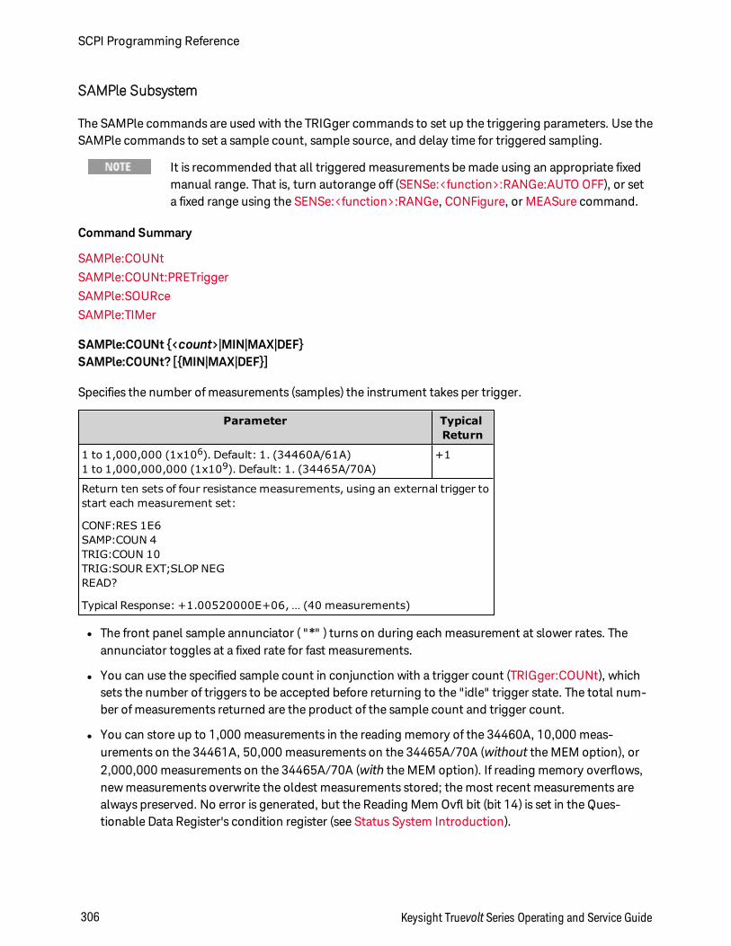
SAMPle Subsystem
The SAMPle commands are used with the TRIGger commands to set up the triggering parameters. Use theSAMPle commands to set a sample count, sample source, and delay time for triggered sampling.
It is recommended that all triggered measurements be made using an appropriate fixedmanual range. That is, turn autorange off (SENSe:<function>:RANGe:AUTO OFF), or seta fixed range using the SENSe:<function>:RANGe, CONFigure, or MEASure command.
Command Summary
SAMPle:COUNt
SAMPle:COUNt:PRETrigger
SAMPle:SOURce
SAMPle:TIMer
SAMPle:COUNt <count>|MIN|MAX|DEFSAMPle:COUNt? [MIN|MAX|DEF]
Specifies the number of measurements (samples) the instrument takes per trigger.
Parameter TypicalReturn
1 to 1,000,000 (1x10⁶). Default: 1. (34460A/61A)1 to 1,000,000,000 (1x10⁹). Default: 1. (34465A/70A)
+1
Return ten sets of four resistance measurements, using an external trigger tostart each measurement set:
CONF:RES 1E6SAMP:COUN 4TRIG:COUN 10TRIG:SOUR EXT;SLOP NEGREAD?
Typical Response: +1.00520000E+06, … (40 measurements)
l The front panel sample annunciator ( "*" ) turns on during each measurement at slower rates. Theannunciator toggles at a fixed rate for fast measurements.
l You can use the specified sample count in conjunction with a trigger count (TRIGger:COUNt), whichsets the number of triggers to be accepted before returning to the "idle" trigger state. The total num-ber of measurements returned are the product of the sample count and trigger count.
l You can store up to 1,000 measurements in the reading memory of the 34460A, 10,000 meas-urements on the 34461A, 50,000 measurements on the 34465A/70A (without the MEM option), or2,000,000 measurements on the 34465A/70A (with the MEM option). If reading memory overflows,new measurements overwrite the oldest measurements stored; the most recent measurements arealways preserved. No error is generated, but the Reading Mem Ovfl bit (bit 14) is set in the Ques-tionable Data Register's condition register (see Status System Introduction).
SCPI Programming Reference
306 Keysight Truevolt Series Operating and Service Guide
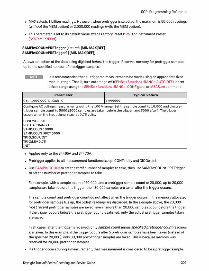
l MAX selects 1 billion readings. However, when pretrigger is selected, the maximum is 50,000 readings(without the MEM option) or 2,000,000 readings (with the MEM option).
l This parameter is set to its default value after a Factory Reset (*RST) or Instrument Preset(SYSTem:PRESet).
SAMPle:COUNt:PRETrigger <count>|MIN|MAX|DEFSAMPle:COUNt:PRETrigger? [MIN|MAX|DEF]
Allows collection of the data being digitized before the trigger. Reserves memory for pretrigger samplesup to the specified number of pretrigger samples.
It is recommended that all triggered measurements be made using an appropriate fixedmanual range. That is, turn autorange off (SENSe:<function>:RANGe:AUTO OFF), or seta fixed range using the SENSe:<function>:RANGe, CONFigure, or MEASure command.
Parameter Typical Return
0 to 1,999,999. Default: 0. +999999
Configure AC voltage measurements using the 100 V range. Set the sample count to 10,000 and the pre-trigger sample count to 5000 (5000 samples are taken before the trigger, and 5000 after). The triggeroccurs when the input signal reaches 0.75 volts.
CONF:VOLT:ACVOLT:AC:RANG 100SAMP:COUN 10000SAMP:COUN:PRET 5000TRIG:SOUR INTTRIG:LEV 0.75INIT
l Applies only to the 34465A and 34470A.
l Pretrigger applies to all measurement functions except CONTinuity and DIODe test.
l Use SAMPle:COUNt to set the total number of samples to take, then use SAMPle:COUNt:PRETriggerto set the number of pretrigger samples to take.
For example, with a sample count of 50,000, and a pretrigger sample count of 20,000, up to 20,000samples are taken before the trigger, then 30,000 samples are taken after the trigger occurs.
The sample count and pretrigger count do not affect when the trigger occurs. If the memory allocatedfor pretrigger samples fills up, the oldest readings are discarded. In the example above, the 20,000most recent pretrigger samples are saved, even if more than 20,000 samples occur before the trigger.If the trigger occurs before the pretrigger count is satisfied, only the actual pretrigger samples takenare saved.
In all cases, after the trigger is received, only sample countminus specified pretrigger count readingsare taken. In this example, if the trigger occurs after 5 pretrigger samples have been taken (instead ofthe specified 20,000), only 30,000 post-trigger samples are taken. This is because memory wasreserved for 20,000 pretrigger samples.
l If a trigger occurs during a measurement, that measurement is considered to be a pretrigger sample.
Keysight Truevolt Series Operating and Service Guide 307
SCPI Programming Reference

l After setting the sample count and pretrigger sample count, you must place the DMM in the "wait-for-trigger" state using INITiate or READ? An external trigger is buffered until the DMM is in the "wait-for-trigger" state.
l The pretrigger sample count must be less than the sample count set with the SAMPle:COUNt com-mand, and there must be at least one post-trigger sample:
Pretrigger Sample Count ≤ Sample Count - 1
l If any of the calculation functions are on (CALC:STAT ON), the pretrigger count is limited to 10,000samples.
l CONFigure and MEASure? set the pretrigger sample count to "0".
l The instrument sets the pretrigger sample count to "0" after a Factory Reset ( *RST command) or a Pre-set (SYSTem:PRESet command).
See Also
SAMPle:COUNt
SAMPle:SOURce IMMediate|TIMerSAMPle:SOURce?
Determines sample timing, with TRIGger:DELay and SAMPle:TIMer to determine sample timing, when thesample count is greater than one.
It is recommended that all triggered measurements be made using an appropriate fixedmanual range. That is, turn autorange off (SENSe:<function>:RANGe:AUTO OFF), or seta fixed range using the SENSe:<function>:RANGe, CONFigure, or MEASure command.
Parameter Typical Return
IMMediate|TIMer. Default: IMMediate. IMM or TIM
Set sample source to timer. The INIT command sets the meter to the "wait-for-trigger" state. When a trig-ger is received from the selected trigger source, the instrument starts taking periodic samples after the trig-ger delay.
SAMP:SOUR TIMSAMP:TIM 0.1INIT
Operation
In all cases, the first sample is taken one trigger delay time after the trigger (the delay being set with theTRIGger:DELay command). Beyond that, the timing mechanism depends on whether you select IMMe-diate (default) or TIMer as the source:
l IMMediate - The first sample starts one trigger delay time after the trigger, and then the trigger delaytime is inserted between the first and second samples, the second and third, and so on:
SCPI Programming Reference
308 Keysight Truevolt Series Operating and Service Guide
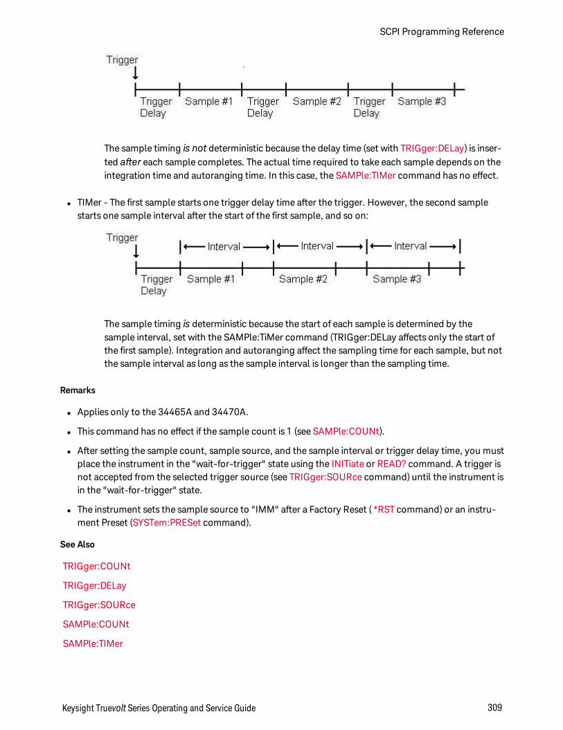
The sample timing is not deterministic because the delay time (set with TRIGger:DELay) is inser-ted after each sample completes. The actual time required to take each sample depends on theintegration time and autoranging time. In this case, the SAMPle:TIMer command has no effect.
l TIMer - The first sample starts one trigger delay time after the trigger. However, the second samplestarts one sample interval after the start of the first sample, and so on:
The sample timing is deterministic because the start of each sample is determined by thesample interval, set with the SAMPle:TiMer command (TRIGger:DELay affects only the start ofthe first sample). Integration and autoranging affect the sampling time for each sample, but notthe sample interval as long as the sample interval is longer than the sampling time.
Remarks
l Applies only to the 34465A and 34470A.
l This command has no effect if the sample count is 1 (see SAMPle:COUNt).
l After setting the sample count, sample source, and the sample interval or trigger delay time, you mustplace the instrument in the "wait-for-trigger" state using the INITiate or READ? command. A trigger isnot accepted from the selected trigger source (see TRIGger:SOURce command) until the instrument isin the "wait-for-trigger" state.
l The instrument sets the sample source to "IMM" after a Factory Reset ( *RST command) or an instru-ment Preset (SYSTem:PRESet command).
See Also
TRIGger:COUNt
TRIGger:DELay
TRIGger:SOURce
SAMPle:COUNt
SAMPle:TIMer
Keysight Truevolt Series Operating and Service Guide 309
SCPI Programming Reference
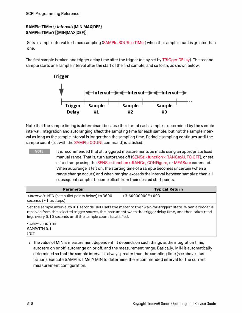
SAMPle:TIMer <interval>|MIN|MAX|DEFSAMPle:TIMer? [MIN|MAX|DEF]
Sets a sample interval for timed sampling (SAMPle:SOURce TIMer) when the sample count is greater thanone.
The first sample is taken one trigger delay time after the trigger (delay set by TRIGger:DELay). The secondsample starts one sample interval after the start of the first sample, and so forth, as shown below:
Note that the sample timing is determinant because the start of each sample is determined by the sampleinterval. Integration and autoranging affect the sampling time for each sample, but not the sample inter-val as long as the sample interval is longer than the sampling time. Periodic sampling continues until thesample count (set with the SAMPle:COUNt command) is satisfied.
It is recommended that all triggered measurements be made using an appropriate fixedmanual range. That is, turn autorange off (SENSe:<function>:RANGe:AUTO OFF), or seta fixed range using the SENSe:<function>:RANGe, CONFigure, or MEASure command.When autorange is left on, the starting time of a sample becomes uncertain (when arange change occurs) and when ranging exceeds the interval between samples; then allsubsequent samples become offset from their desired start points.
Parameter Typical Return
<interval> MIN (see bullet points below) to 3600seconds (~1 µs steps).
+3.60000000E+003
Set the sample interval to 0.1 seconds. INIT sets the meter to the "wait-for-trigger" state. When a trigger isreceived from the selected trigger source, the instrument waits the trigger delay time, and then takes read-ings every 0.10 seconds until the sample count is satisfied.
SAMP:SOUR TIMSAMP:TIM 0.1INIT
l The value of MIN is measurement dependent. It depends on such things as the integration time,autozero on or off, autorange on or off, and the measurement range. Basically, MIN is automaticallydetermined so that the sample interval is always greater than the sampling time (see above illus-tration). Execute SAMPle:TIMer? MIN to determine the recommended interval for the currentmeasurement configuration.
SCPI Programming Reference
310 Keysight Truevolt Series Operating and Service Guide
l Since the minimum value changes depending on configuration, a command order dependency exists.You must completely configure the measurement before setting the sample timer to MIN, or you maygenerate an error. A complete configuration includes such things as math statistics or scaling.
l When using autorange, the MIN value is the recommended value, not the absolute minimum value.With autorange enabled, MIN is calculated assuming a single range change will occur for every meas-urement (not multiple ranges, just one range up or down per measurement). You can specify an <inter-val> between the absolute minimum (assumes no range changes) and the recommended MIN value,but it may generate a timing violation error when making measurements. Applying a value less thanthe absolute minimum will generate an error.
l To determine the absolute minimum value for the present configuration, set the sample time to 20 µs(which may generate a settings conflict error), then read back the current sample timer value using theSAMPle:TIMer? query. The sample source must be set to timer with a sample count or trigger countgreater than 1, for the settings conflict error to occur. The settings conflict error causes the timer to beset to the absolute minimum value.
l The sample time resolution is 1 µs, the aperture resolution is 2 us, and the actual hardware resolutionis not exactly 1 µs. There are cases where a sample time value, rounded to the nearest hardware res-olution, will result in a smaller value than aperture when rounded to 2 µs. This will create error -221,"Settings conflict; cannot meet requested timing; SAMP:TIM changed". For example, the fol-lowing sequence of commands generates error -221 and sets the sample time to +2.00100000E-003.
*RST FUNC "VOLT:DC" VOLT:DC:APER 0.002 VOLT:DC:RANGE:AUTO OFF VOLT:DC:ZERO:AUTO OFF TRIG:DEL 0 TRIG:SOUR BUS SAMP:COUN 2 SAMP:TIM 0.002 SAMP:SOUR TIM
This error can also occur if you attempt to set both values an odd number of µs. For example, settingboth values to 23 µs, generates error -221 and sets the sample timer to 24 µs.
l After setting the sample count, source, and delay time, you must place the meter in the "wait-for-trig-ger" state using the INITiate or READ? command. A trigger is not accepted from the selected triggersource (see TRIGger:SOURce command) until the instrument is in the "wait-for-trigger" state.
l The interval may be set to any value from the absolute minimum described above to 3600 seconds.However, the value is rounded to the nearest step. For dc measurements, the step size is 1 µs. For acmeasurements, it is ac bandwidth dependent.
l The instrument sets the sample timer to 1 second after a reset ( *RST command) or an instrument pre-set (SYSTem:PRESet command).
See Also
TRIGger:COUNt
Keysight Truevolt Series Operating and Service Guide 311
SCPI Programming Reference

TRIGger:DELay
TRIGger:SOURce
SAMPle:COUNt
SAMPle:SOURce
SCPI Programming Reference
312 Keysight Truevolt Series Operating and Service Guide
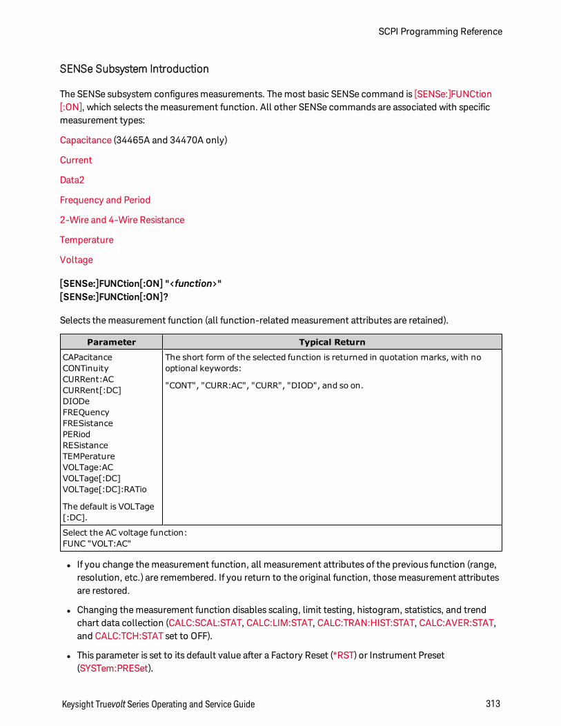
SENSe Subsystem Introduction
The SENSe subsystem configures measurements. The most basic SENSe command is [SENSe:]FUNCtion[:ON], which selects the measurement function. All other SENSe commands are associated with specificmeasurement types:
Capacitance (34465A and 34470A only)
Current
Data2
Frequency and Period
2-Wire and 4-Wire Resistance
Temperature
Voltage
[SENSe:]FUNCtion[:ON] "<function>"[SENSe:]FUNCtion[:ON]?
Selects the measurement function (all function-related measurement attributes are retained).
Parameter Typical Return
CAPacitanceCONTinuityCURRent:ACCURRent[:DC]DIODeFREQuencyFRESistancePERiodRESistanceTEMPeratureVOLTage:ACVOLTage[:DC]VOLTage[:DC]:RATio
The default is VOLTage[:DC].
The short form of the selected function is returned in quotation marks, with nooptional keywords:
"CONT", "CURR:AC", "CURR", "DIOD", and so on.
Select the AC voltage function:FUNC "VOLT:AC"
l If you change the measurement function, all measurement attributes of the previous function (range,resolution, etc.) are remembered. If you return to the original function, those measurement attributesare restored.
l Changing the measurement function disables scaling, limit testing, histogram, statistics, and trendchart data collection (CALC:SCAL:STAT, CALC:LIM:STAT, CALC:TRAN:HIST:STAT, CALC:AVER:STAT,and CALC:TCH:STAT set to OFF).
l This parameter is set to its default value after a Factory Reset (*RST) or Instrument Preset(SYSTem:PRESet).
Keysight Truevolt Series Operating and Service Guide 313
SCPI Programming Reference
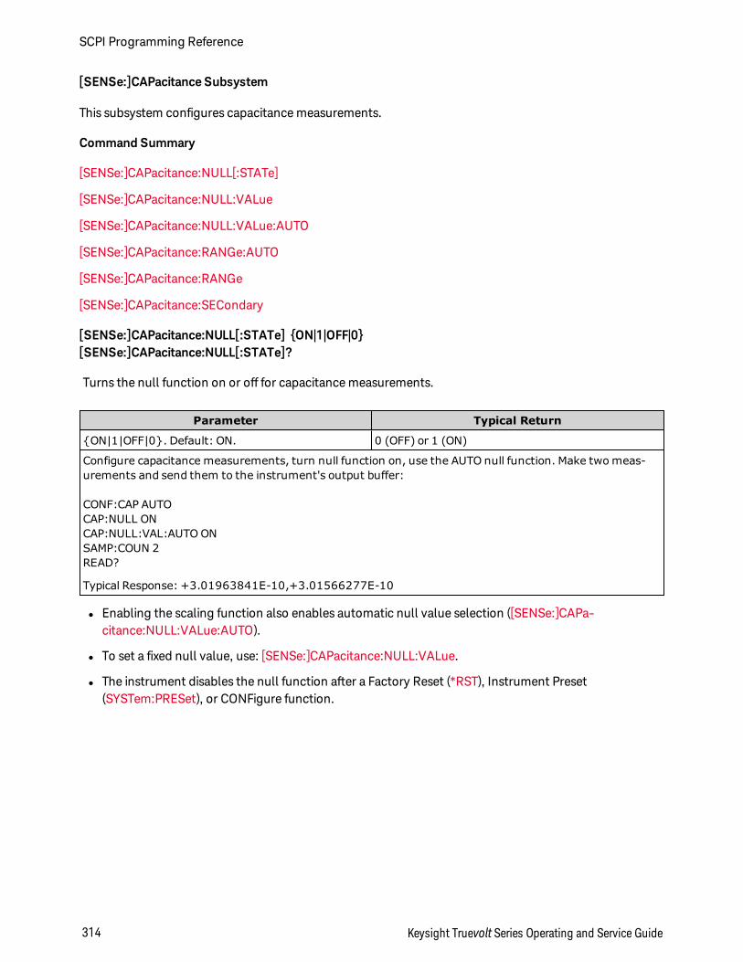
[SENSe:]CAPacitance Subsystem
This subsystem configures capacitance measurements.
Command Summary
[SENSe:]CAPacitance:NULL[:STATe]
[SENSe:]CAPacitance:NULL:VALue
[SENSe:]CAPacitance:NULL:VALue:AUTO
[SENSe:]CAPacitance:RANGe:AUTO
[SENSe:]CAPacitance:RANGe
[SENSe:]CAPacitance:SECondary
[SENSe:]CAPacitance:NULL[:STATe] ON|1|OFF|0[SENSe:]CAPacitance:NULL[:STATe]?
Turns the null function on or off for capacitance measurements.
Parameter Typical Return
ON|1|OFF|0. Default: ON. 0 (OFF) or 1 (ON)
Configure capacitance measurements, turn null function on, use the AUTO null function. Make two meas-urements and send them to the instrument's output buffer:
CONF:CAP AUTOCAP:NULL ONCAP:NULL:VAL:AUTO ONSAMP:COUN 2READ?
Typical Response: +3.01963841E-10,+3.01566277E-10
l Enabling the scaling function also enables automatic null value selection ([SENSe:]CAPa-citance:NULL:VALue:AUTO).
l To set a fixed null value, use: [SENSe:]CAPacitance:NULL:VALue.
l The instrument disables the null function after a Factory Reset (*RST), Instrument Preset(SYSTem:PRESet), or CONFigure function.
SCPI Programming Reference
314 Keysight Truevolt Series Operating and Service Guide
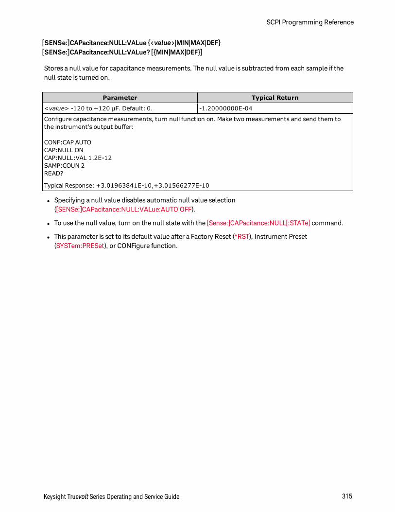
[SENSe:]CAPacitance:NULL:VALue <value>|MIN|MAX|DEF[SENSe:]CAPacitance:NULL:VALue? [MIN|MAX|DEF]
Stores a null value for capacitance measurements. The null value is subtracted from each sample if thenull state is turned on.
Parameter Typical Return
<value> -120 to +120 µF. Default: 0. -1.20000000E-04
Configure capacitance measurements, turn null function on. Make two measurements and send them tothe instrument's output buffer:
CONF:CAP AUTOCAP:NULL ONCAP:NULL:VAL 1.2E-12SAMP:COUN 2READ?
Typical Response: +3.01963841E-10,+3.01566277E-10
l Specifying a null value disables automatic null value selection([SENSe:]CAPacitance:NULL:VALue:AUTO OFF).
l To use the null value, turn on the null state with the [Sense:]CAPacitance:NULL[:STATe] command.
l This parameter is set to its default value after a Factory Reset (*RST), Instrument Preset(SYSTem:PRESet), or CONFigure function.
Keysight Truevolt Series Operating and Service Guide 315
SCPI Programming Reference
[SENSe:]CAPacitance:NULL:VALue:AUTO ON|1|OFF|0[SENSe:]CAPacitance:NULL:VALue:AUTO?
Enables or disables automatic null value selection for capacitance measurements.
Parameter Typical Return
ON|1|OFF|0. Default: ON. 0 (OFF) or 1 (ON)
Configure capacitance measurements, turn null function on, use the AUTO null function. Make two meas-urements and send them to the instrument's output buffer:
CONF:CAP AUTOCAP:NULL ONCAP:NULL:VAL:AUTO ONSAMP:COUN 2READ?
Typical Response: +3.01963841E-10,+3.01566277E-10
l When automatic reference selection is ON, the first measurement made is used as the null value for allsubsequent measurements.[SENSe:]CAPacitance:NULL:VALue is set to this value. Automatic nullvalue selection will be disabled.
l When automatic null value selection is disabled (OFF), the null value is specified by:[SENSe:]CAPa-citance:NULL:VALue.
l The instrument enables automatic null value selection when the null function is enabled([SENSe:]CAPacitance:NULL:STATe ON).
l This parameter is set to its default value after a Factory Reset (*RST), Instrument Preset(SYSTem:PRESet), or CONFigure function.
[SENSe:]CAPacitance:RANGe:AUTO OFF|ON|ONCE[SENSe:]CAPacitance:RANGe:AUTO?
Disables or enables autoranging for capacitance measurements.
Parameter Typical Return
OFF|ON|ONCE. Default: ON. 0 (OFF) or 1 (ON)
Configure capacitance measurements, turn autorange on, turn null function on, use the AUTO null function.Make two measurements and send them to the instrument's output buffer:
CONF:CAPCAP:RANG:AUTO ONCAP:NULL ONCAP:NULL:VAL:AUTO ONSAMP:COUN 2READ?
Typical Response: +3.01963841E-10,+3.01566277E-10
l Autoranging goes down a range at less than 10% of range and up a range at greater than 120% ofrange. For capacitance measurements only, when autorange is off, the instrument does not report an
SCPI Programming Reference
316 Keysight Truevolt Series Operating and Service Guide
overload for readings greater than 120% of range. Overload only occurs when the algorithm times outbecause the applied capacitance is too large for the algorithm to measure. If you apply a DC voltage ora short to the input terminals in capacitance measurement mode, the instrument reports an overload.
l ONCE performs an immediate autorange, and then sets autoranging to OFF. (Thus, the query returns"0".)
l Selecting a discrete range (see [Sense:]CAPacitance:RANGe command) disables autoranging.
l This parameter is set to its default value after a Factory Reset (*RST) or Instrument Preset(SYSTem:PRESet).
[SENSe:]CAPacitance:RANGe <range>|MIN|MAX|DEF[SENSe:]CAPacitance:RANGe? [MIN|MAX|DEF]
Selects a fixed range for capacitance measurements.
Parameter Typical Return
<range>: 1 nF|10 nF|100 nF|1 µF|10 µF|100 µF.Default: AUTO.
+1.00000000E-09
Configure capacitance measurements, select 1 nF range, turn null function on, use the AUTO null function.Make two measurements and send them to the instrument's output buffer:
CONF:CAPCAP:RANG 1 nF or CAP:RANG 1.0E-9CAP:NULL ONCAP:NULL:VAL:AUTO ONSAMP:COUN 2READ?
Typical Response: +3.01963841E-10,+3.01566277E-10
l Selecting a fixed range ([SENSe:]<function>:RANGe) disables autoranging.
l If the input signal is greater than can be measured on the specified fixed range, the instrument displaysOverload on front panel and returns "9.9E37" from the remote interface.
l This parameter is set to its default value after a Factory Reset (*RST) or Instrument Preset(SYSTem:PRESet).
Keysight Truevolt Series Operating and Service Guide 317
SCPI Programming Reference
[SENSe:]CAPacitance:SECondary "OFF"|"CALCulate:DATA"[SENSe:]CAPacitance:SECondary?
Selects the secondary measurement function for capacitance measurements.
Parameter Typical Return
"OFF"|"CALCulate:DATA", default "OFF" "CALC:DATA"
Configure capacitance and secondary measurements. Make capacitance measurement and retrieve sec-ondary measurement.
CONF:CAP AUTO,MAXCAP:SEC "CALC:DATA"READ?;DATA2?
Typical Response: +3.01566373E-10;+3.01566373E-10
l "CALCulate:DATA" - The measurement value before any math operations are done (including NULL).
l Use READ? or INITiate to start the measurement. Use [SENSe:]DATA2? to retrieve the secondary meas-urement.
l This parameter is set to its default value after a Factory Reset (*RST) or Instrument Preset(SYSTem:PRESet).
SCPI Programming Reference
318 Keysight Truevolt Series Operating and Service Guide
[SENSe:]CURRent Subsystem
This subsystem configures AC and DC current measurements.
Command Summary
[SENSe:]CURRent:AC:BANDwidth
[SENSe:]CURRent:AC|DC:NULL[:STATe]
[SENSe:]CURRent:AC|DC:NULL:VALue
[SENSe:]CURRent:AC|DC:NULL:VALue:AUTO
[SENSe:]CURRent:AC|DC:RANGe
[SENSe:]CURRent:AC|DC:RANGe:AUTO
[SENSe:]CURRent:AC|DC:TERMinals
[SENSe:]CURRent:AC:SECondary
[SENSe:]CURRent[:DC]:APERture
[SENSe:]CURRent[:DC]:APERture:ENABled
[SENSe:]CURRent[:DC]:NPLC
[SENSe:]CURRent[:DC]:RESolution
[SENSe:]CURRent[:DC]:SECondary
[SENSe:]CURRent[:DC]:ZERO:AUTO
[SENSe:]CURRent:SWITch:MODE
Keysight Truevolt Series Operating and Service Guide 319
SCPI Programming Reference
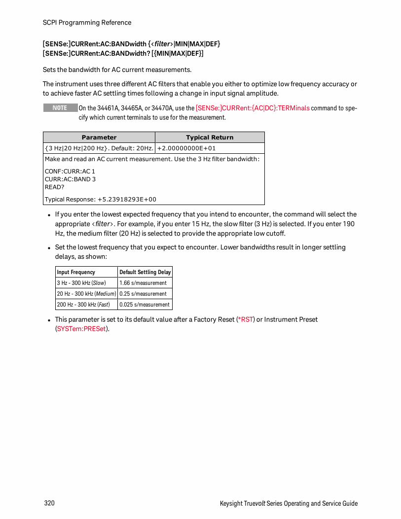
[SENSe:]CURRent:AC:BANDwidth <filter>|MIN|MAX|DEF[SENSe:]CURRent:AC:BANDwidth? [MIN|MAX|DEF]
Sets the bandwidth for AC current measurements.
The instrument uses three different AC filters that enable you either to optimize low frequency accuracy orto achieve faster AC settling times following a change in input signal amplitude.
On the 34461A, 34465A, or 34470A, use the [SENSe:]CURRent:AC|DC:TERMinals command to spe-cify which current terminals to use for the measurement.
Parameter Typical Return
3 Hz|20 Hz|200 Hz. Default: 20Hz. +2.00000000E+01
Make and read an AC current measurement. Use the 3 Hz filter bandwidth:
CONF:CURR:AC 1CURR:AC:BAND 3READ?
Typical Response: +5.23918293E+00
l If you enter the lowest expected frequency that you intend to encounter, the command will select theappropriate <filter>. For example, if you enter 15 Hz, the slow filter (3 Hz) is selected. If you enter 190Hz, the medium filter (20 Hz) is selected to provide the appropriate low cutoff.
l Set the lowest frequency that you expect to encounter. Lower bandwidths result in longer settlingdelays, as shown:
Input Frequency Default Settling Delay
3 Hz - 300 kHz (Slow) 1.66 s/measurement
20 Hz - 300 kHz (Medium) 0.25 s/measurement
200 Hz - 300 kHz (Fast) 0.025 s/measurement
l This parameter is set to its default value after a Factory Reset (*RST) or Instrument Preset(SYSTem:PRESet).
SCPI Programming Reference
320 Keysight Truevolt Series Operating and Service Guide
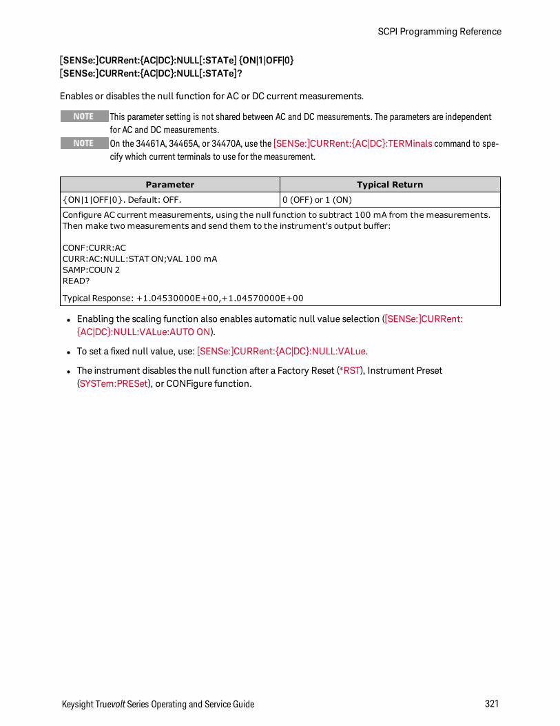
[SENSe:]CURRent:AC|DC:NULL[:STATe] ON|1|OFF|0[SENSe:]CURRent:AC|DC:NULL[:STATe]?
Enables or disables the null function for AC or DC current measurements.
This parameter setting is not shared between AC and DC measurements. The parameters are independentfor AC and DC measurements.On the 34461A, 34465A, or 34470A, use the [SENSe:]CURRent:AC|DC:TERMinals command to spe-cify which current terminals to use for the measurement.
Parameter Typical Return
ON|1|OFF|0. Default: OFF. 0 (OFF) or 1 (ON)
Configure AC current measurements, using the null function to subtract 100 mA from the measurements.Then make two measurements and send them to the instrument's output buffer:
CONF:CURR:ACCURR:AC:NULL:STAT ON;VAL 100 mASAMP:COUN 2READ?
Typical Response: +1.04530000E+00,+1.04570000E+00
l Enabling the scaling function also enables automatic null value selection ([SENSe:]CURRent:AC|DC:NULL:VALue:AUTO ON).
l To set a fixed null value, use: [SENSe:]CURRent:AC|DC:NULL:VALue.
l The instrument disables the null function after a Factory Reset (*RST), Instrument Preset(SYSTem:PRESet), or CONFigure function.
Keysight Truevolt Series Operating and Service Guide 321
SCPI Programming Reference
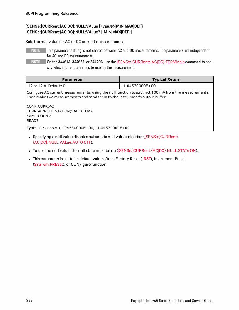
[SENSe:]CURRent:AC|DC:NULL:VALue <value>|MIN|MAX|DEF[SENSe:]CURRent:AC|DC:NULL:VALue? [MIN|MAX|DEF]
Sets the null value for AC or DC current measurements.
This parameter setting is not shared between AC and DC measurements. The parameters are independentfor AC and DC measurements.On the 34461A, 34465A, or 34470A, use the [SENSe:]CURRent:AC|DC:TERMinals command to spe-cify which current terminals to use for the measurement.
Parameter Typical Return
-12 to 12 A. Default: 0 +1.04530000E+00
Configure AC current measurements, using the null function to subtract 100 mA from the measurements.Then make two measurements and send them to the instrument's output buffer:
CONF:CURR:ACCURR:AC:NULL:STAT ON;VAL 100 mASAMP:COUN 2READ?
Typical Response: +1.04530000E+00,+1.04570000E+00
l Specifying a null value disables automatic null value selection ([SENSe:]CURRent:AC|DC:NULL:VALue:AUTO OFF).
l To use the null value, the null state must be on ([SENSe:]CURRent:AC|DC:NULL:STATe ON).
l This parameter is set to its default value after a Factory Reset (*RST), Instrument Preset(SYSTem:PRESet), or CONFigure function.
SCPI Programming Reference
322 Keysight Truevolt Series Operating and Service Guide
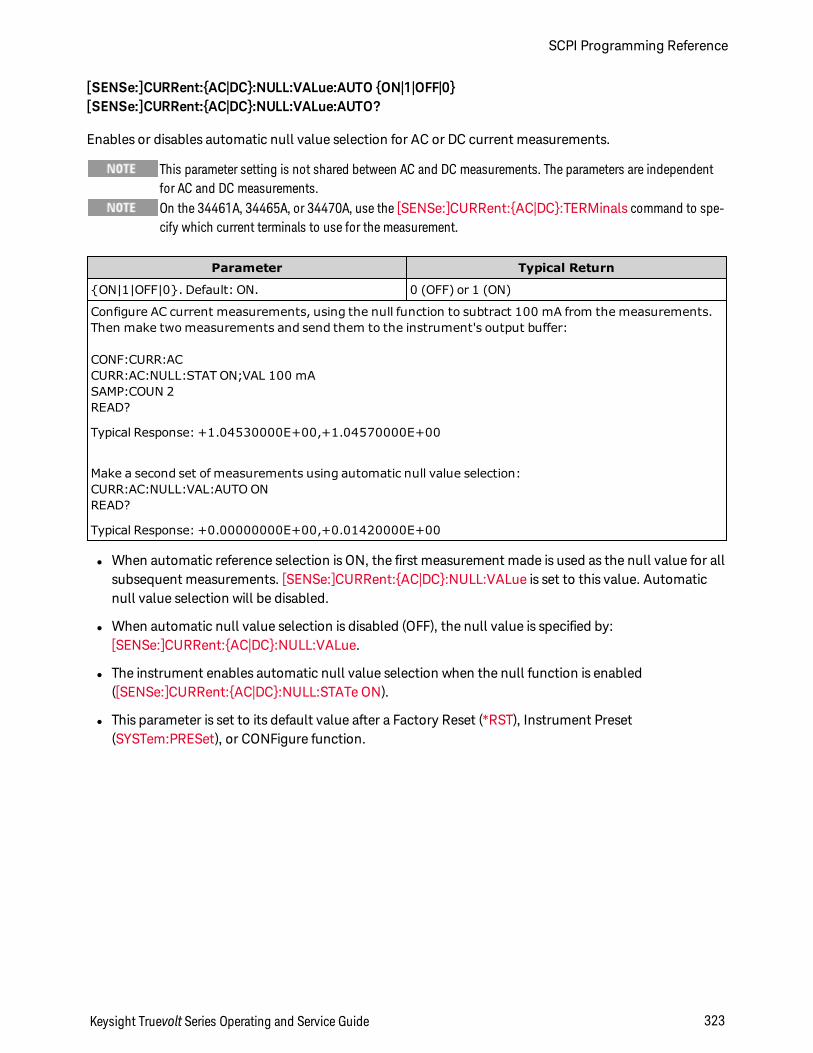
[SENSe:]CURRent:AC|DC:NULL:VALue:AUTO ON|1|OFF|0[SENSe:]CURRent:AC|DC:NULL:VALue:AUTO?
Enables or disables automatic null value selection for AC or DC current measurements.
This parameter setting is not shared between AC and DC measurements. The parameters are independentfor AC and DC measurements.On the 34461A, 34465A, or 34470A, use the [SENSe:]CURRent:AC|DC:TERMinals command to spe-cify which current terminals to use for the measurement.
Parameter Typical Return
ON|1|OFF|0. Default: ON. 0 (OFF) or 1 (ON)
Configure AC current measurements, using the null function to subtract 100 mA from the measurements.Then make two measurements and send them to the instrument's output buffer:
CONF:CURR:ACCURR:AC:NULL:STAT ON;VAL 100 mASAMP:COUN 2READ?
Typical Response: +1.04530000E+00,+1.04570000E+00
Make a second set of measurements using automatic null value selection:CURR:AC:NULL:VAL:AUTO ONREAD?
Typical Response: +0.00000000E+00,+0.01420000E+00
l When automatic reference selection is ON, the first measurement made is used as the null value for allsubsequent measurements. [SENSe:]CURRent:AC|DC:NULL:VALue is set to this value. Automaticnull value selection will be disabled.
l When automatic null value selection is disabled (OFF), the null value is specified by:[SENSe:]CURRent:AC|DC:NULL:VALue.
l The instrument enables automatic null value selection when the null function is enabled([SENSe:]CURRent:AC|DC:NULL:STATe ON).
l This parameter is set to its default value after a Factory Reset (*RST), Instrument Preset(SYSTem:PRESet), or CONFigure function.
Keysight Truevolt Series Operating and Service Guide 323
SCPI Programming Reference
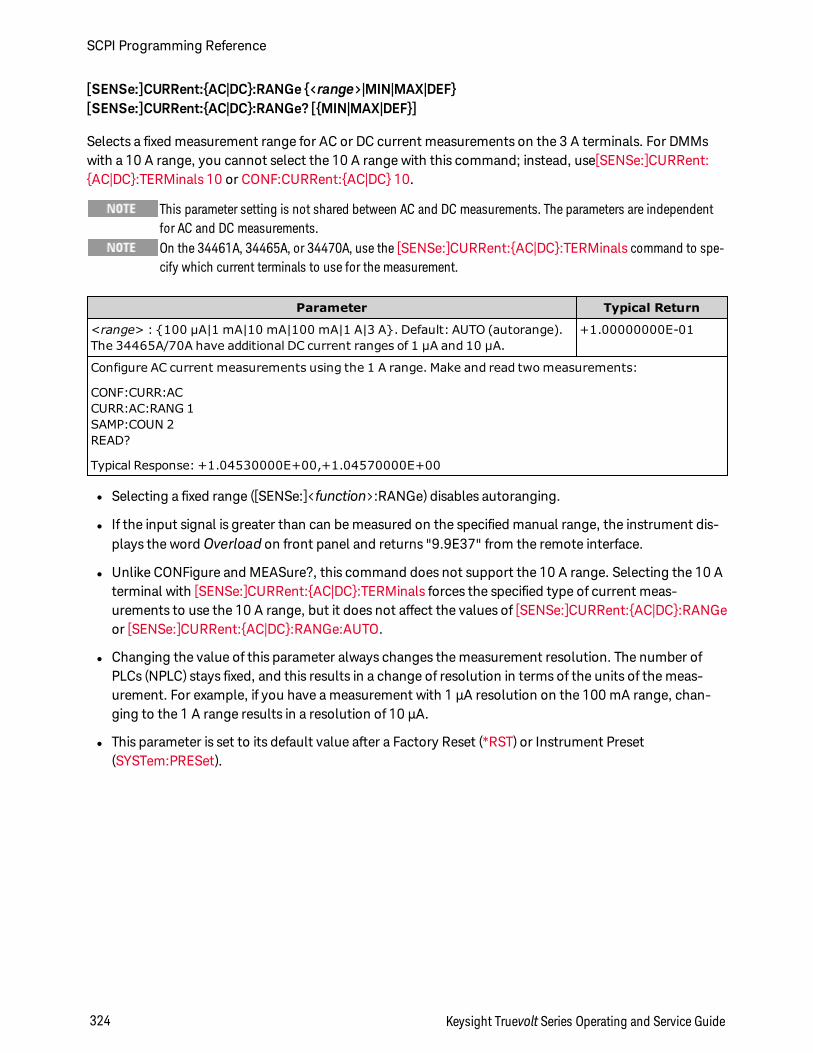
[SENSe:]CURRent:AC|DC:RANGe <range>|MIN|MAX|DEF[SENSe:]CURRent:AC|DC:RANGe? [MIN|MAX|DEF]
Selects a fixed measurement range for AC or DC current measurements on the 3 A terminals. For DMMswith a 10 A range, you cannot select the 10 A range with this command; instead, use[SENSe:]CURRent:AC|DC:TERMinals 10 or CONF:CURRent:AC|DC 10.
This parameter setting is not shared between AC and DC measurements. The parameters are independentfor AC and DC measurements.On the 34461A, 34465A, or 34470A, use the [SENSe:]CURRent:AC|DC:TERMinals command to spe-cify which current terminals to use for the measurement.
Parameter Typical Return
<range> : 100 µA|1 mA|10 mA|100 mA|1 A|3 A. Default: AUTO (autorange).The 34465A/70A have additional DC current ranges of 1 µA and 10 µA.
+1.00000000E-01
Configure AC current measurements using the 1 A range. Make and read two measurements:
CONF:CURR:ACCURR:AC:RANG 1SAMP:COUN 2READ?
Typical Response: +1.04530000E+00,+1.04570000E+00
l Selecting a fixed range ([SENSe:]<function>:RANGe) disables autoranging.
l If the input signal is greater than can be measured on the specified manual range, the instrument dis-plays the word Overload on front panel and returns "9.9E37" from the remote interface.
l Unlike CONFigure and MEASure?, this command does not support the 10 A range. Selecting the 10 Aterminal with [SENSe:]CURRent:AC|DC:TERMinals forces the specified type of current meas-urements to use the 10 A range, but it does not affect the values of [SENSe:]CURRent:AC|DC:RANGeor [SENSe:]CURRent:AC|DC:RANGe:AUTO.
l Changing the value of this parameter always changes the measurement resolution. The number ofPLCs (NPLC) stays fixed, and this results in a change of resolution in terms of the units of the meas-urement. For example, if you have a measurement with 1 µA resolution on the 100 mA range, chan-ging to the 1 A range results in a resolution of 10 µA.
l This parameter is set to its default value after a Factory Reset (*RST) or Instrument Preset(SYSTem:PRESet).
SCPI Programming Reference
324 Keysight Truevolt Series Operating and Service Guide
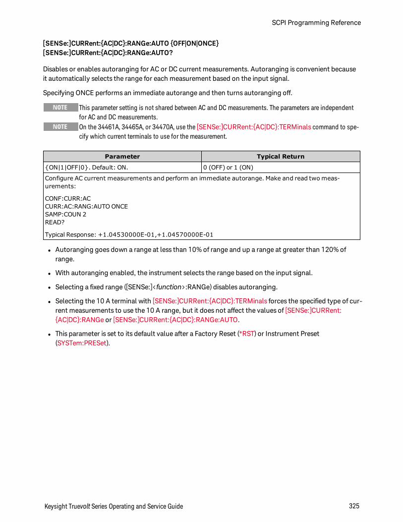
[SENSe:]CURRent:AC|DC:RANGe:AUTO OFF|ON|ONCE[SENSe:]CURRent:AC|DC:RANGe:AUTO?
Disables or enables autoranging for AC or DC current measurements. Autoranging is convenient becauseit automatically selects the range for each measurement based on the input signal.
Specifying ONCE performs an immediate autorange and then turns autoranging off.
This parameter setting is not shared between AC and DC measurements. The parameters are independentfor AC and DC measurements.On the 34461A, 34465A, or 34470A, use the [SENSe:]CURRent:AC|DC:TERMinals command to spe-cify which current terminals to use for the measurement.
Parameter Typical Return
ON|1|OFF|0. Default: ON. 0 (OFF) or 1 (ON)
Configure AC current measurements and perform an immediate autorange. Make and read two meas-urements:
CONF:CURR:ACCURR:AC:RANG:AUTO ONCESAMP:COUN 2READ?
Typical Response: +1.04530000E-01,+1.04570000E-01
l Autoranging goes down a range at less than 10% of range and up a range at greater than 120% ofrange.
l With autoranging enabled, the instrument selects the range based on the input signal.
l Selecting a fixed range ([SENSe:]<function>:RANGe) disables autoranging.
l Selecting the 10 A terminal with [SENSe:]CURRent:AC|DC:TERMinals forces the specified type of cur-rent measurements to use the 10 A range, but it does not affect the values of [SENSe:]CURRent:AC|DC:RANGe or [SENSe:]CURRent:AC|DC:RANGe:AUTO.
l This parameter is set to its default value after a Factory Reset (*RST) or Instrument Preset(SYSTem:PRESet).
Keysight Truevolt Series Operating and Service Guide 325
SCPI Programming Reference
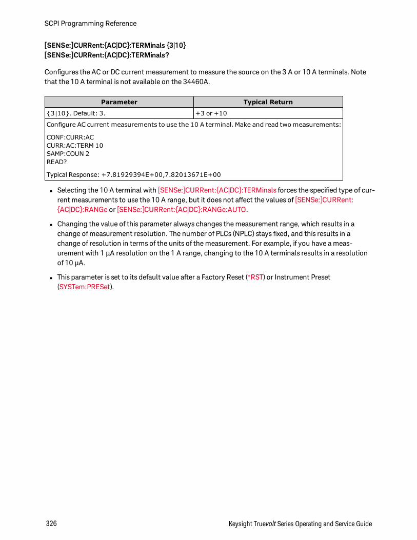
[SENSe:]CURRent:AC|DC:TERMinals 3|10[SENSe:]CURRent:AC|DC:TERMinals?
Configures the AC or DC current measurement to measure the source on the 3 A or 10 A terminals. Notethat the 10 A terminal is not available on the 34460A.
Parameter Typical Return
3|10. Default: 3. +3 or +10
Configure AC current measurements to use the 10 A terminal. Make and read two measurements:
CONF:CURR:ACCURR:AC:TERM 10SAMP:COUN 2READ?
Typical Response: +7.81929394E+00,7.82013671E+00
l Selecting the 10 A terminal with [SENSe:]CURRent:AC|DC:TERMinals forces the specified type of cur-rent measurements to use the 10 A range, but it does not affect the values of [SENSe:]CURRent:AC|DC:RANGe or [SENSe:]CURRent:AC|DC:RANGe:AUTO.
l Changing the value of this parameter always changes the measurement range, which results in achange of measurement resolution. The number of PLCs (NPLC) stays fixed, and this results in achange of resolution in terms of the units of the measurement. For example, if you have a meas-urement with 1 µA resolution on the 1 A range, changing to the 10 A terminals results in a resolutionof 10 µA.
l This parameter is set to its default value after a Factory Reset (*RST) or Instrument Preset(SYSTem:PRESet).
SCPI Programming Reference
326 Keysight Truevolt Series Operating and Service Guide

[SENSe:]CURRent:AC:SECondary "OFF"|"CALCulate:DATA"|"FREQuency"|"CURRent[:DC]"[SENSe:]CURRent:AC:SECondary?
Selects the secondary measurement function for AC current measurements.
Parameter Typical Return
"OFF"|"CALCulate:DATA"|"FREQuency"|"CURRent[:DC]",default "OFF"
"CALC:DATA"
Configure AC current measurements using the 1 A range. Select frequency as the secondarymeasurement. Make and retrieve measurements.
CONF:CURR:AC 1CURR:AC:SEC "FREQ"READ?;DATA2?
Typical Response: +0.50000000E+00;+1.00000000E+03
l "CALCulate:DATA" - (Applies only to the 34465A and 34470A.) The measurement value before anymath operations are done (including NULL).
l "FREQuency" - The frequency measurement of the input signal.
l "CURRent[:DC]" – The DC current measurement of the input signal. Applies only when using the instru-ment from the front panel. Setting is ignored for measurements made from a remote interface. If yourequire both AC and DC current measurements from remote, program each function separately, seeCONFigure:CURRent:AC|DC.
l This parameter is set to its default value after a Factory Reset (*RST) or Instrument Preset(SYSTem:PRESet).
[SENSe:]CURRent[:DC]:APERture <seconds>|MIN|MAX|DEF[SENSe:]CURRent[:DC]:APERture? [MIN|MAX|DEF]
Specifies the integration time in seconds (called aperture time) for dc current measurements.
Use this command for precise control of the DMM's integration time. Use NPLC (see[SENSe:]CURRent[:DC]:NPLC ) for better power-line noise rejection characteristics(NPLC > 1).
Parameter Typical Return
(Without the DIG option) 200 µs to 1 s (2 µs resolution), default: 100 ms. (With the DIGoption) 20 µs to 1 s (2 µs resolution), default: 100 ms.
+1.00000000E-01
Enable aperture time mode, set the aperture time to 300 ms:
CURR:APER:ENAB ONCURR:DC:APER 300E-03
Keysight Truevolt Series Operating and Service Guide 327
SCPI Programming Reference
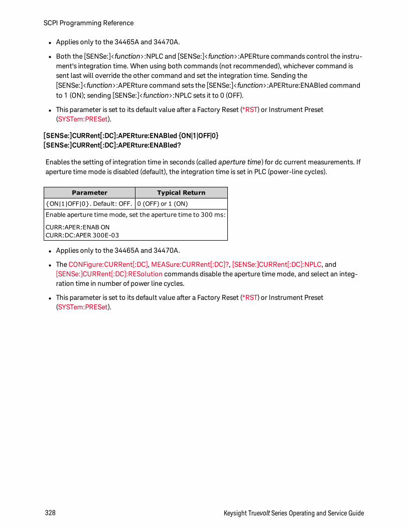
l Applies only to the 34465A and 34470A.
l Both the [SENSe:]<function>:NPLC and [SENSe:]<function>:APERture commands control the instru-ment's integration time. When using both commands (not recommended), whichever command issent last will override the other command and set the integration time. Sending the[SENSe:]<function>:APERture command sets the [SENSe:]<function>:APERture:ENABled commandto 1 (ON); sending [SENSe:]<function>:NPLC sets it to 0 (OFF).
l This parameter is set to its default value after a Factory Reset (*RST) or Instrument Preset(SYSTem:PRESet).
[SENSe:]CURRent[:DC]:APERture:ENABled ON|1|OFF|0[SENSe:]CURRent[:DC]:APERture:ENABled?
Enables the setting of integration time in seconds (called aperture time) for dc current measurements. Ifaperture time mode is disabled (default), the integration time is set in PLC (power-line cycles).
Parameter Typical Return
ON|1|OFF|0. Default: OFF. 0 (OFF) or 1 (ON)
Enable aperture time mode, set the aperture time to 300 ms:
CURR:APER:ENAB ONCURR:DC:APER 300E-03
l Applies only to the 34465A and 34470A.
l The CONFigure:CURRent[:DC], MEASure:CURRent[:DC]?, [SENSe:]CURRent[:DC]:NPLC, and[SENSe:]CURRent[:DC]:RESolution commands disable the aperture time mode, and select an integ-ration time in number of power line cycles.
l This parameter is set to its default value after a Factory Reset (*RST) or Instrument Preset(SYSTem:PRESet).
SCPI Programming Reference
328 Keysight Truevolt Series Operating and Service Guide
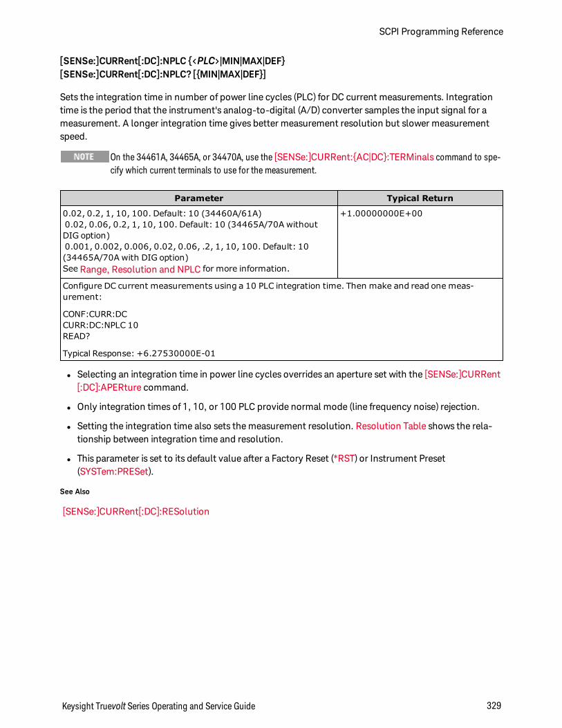
[SENSe:]CURRent[:DC]:NPLC <PLC>|MIN|MAX|DEF[SENSe:]CURRent[:DC]:NPLC? [MIN|MAX|DEF]
Sets the integration time in number of power line cycles (PLC) for DC current measurements. Integrationtime is the period that the instrument's analog-to-digital (A/D) converter samples the input signal for ameasurement. A longer integration time gives better measurement resolution but slower measurementspeed.
On the 34461A, 34465A, or 34470A, use the [SENSe:]CURRent:AC|DC:TERMinals command to spe-cify which current terminals to use for the measurement.
Parameter Typical Return
0.02, 0.2, 1, 10, 100. Default: 10 (34460A/61A)0.02, 0.06, 0.2, 1, 10, 100. Default: 10 (34465A/70A withoutDIG option)0.001, 0.002, 0.006, 0.02, 0.06, .2, 1, 10, 100. Default: 10(34465A/70A with DIG option)See Range, Resolution and NPLC for more information.
+1.00000000E+00
Configure DC current measurements using a 10 PLC integration time. Then make and read one meas-urement:
CONF:CURR:DCCURR:DC:NPLC 10READ?
Typical Response: +6.27530000E-01
l Selecting an integration time in power line cycles overrides an aperture set with the [SENSe:]CURRent[:DC]:APERture command.
l Only integration times of 1, 10, or 100 PLC provide normal mode (line frequency noise) rejection.
l Setting the integration time also sets the measurement resolution. Resolution Table shows the rela-tionship between integration time and resolution.
l This parameter is set to its default value after a Factory Reset (*RST) or Instrument Preset(SYSTem:PRESet).
See Also
[SENSe:]CURRent[:DC]:RESolution
Keysight Truevolt Series Operating and Service Guide 329
SCPI Programming Reference
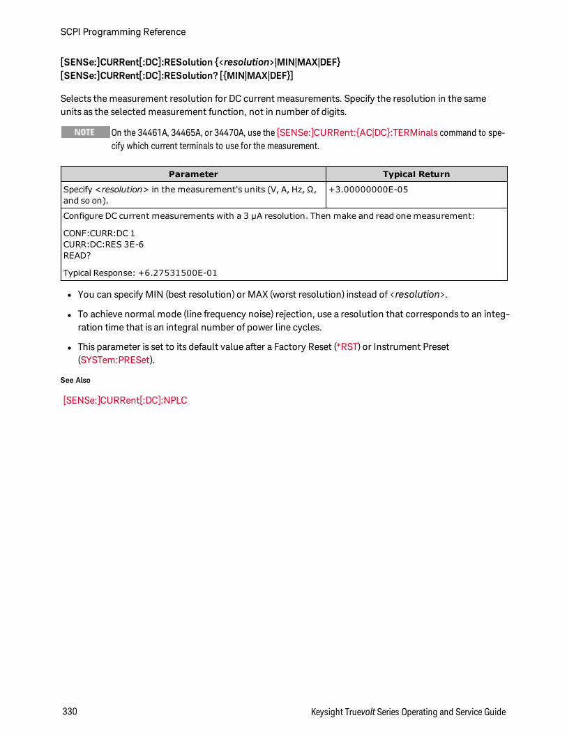
[SENSe:]CURRent[:DC]:RESolution <resolution>|MIN|MAX|DEF[SENSe:]CURRent[:DC]:RESolution? [MIN|MAX|DEF]
Selects the measurement resolution for DC current measurements. Specify the resolution in the sameunits as the selected measurement function, not in number of digits.
On the 34461A, 34465A, or 34470A, use the [SENSe:]CURRent:AC|DC:TERMinals command to spe-cify which current terminals to use for the measurement.
Parameter Typical Return
Specify <resolution> in the measurement's units (V, A, Hz, Ω,and so on).
+3.00000000E-05
Configure DC current measurements with a 3 µA resolution. Then make and read one measurement:
CONF:CURR:DC 1CURR:DC:RES 3E-6READ?
Typical Response: +6.27531500E-01
l You can specify MIN (best resolution) or MAX (worst resolution) instead of <resolution>.
l To achieve normal mode (line frequency noise) rejection, use a resolution that corresponds to an integ-ration time that is an integral number of power line cycles.
l This parameter is set to its default value after a Factory Reset (*RST) or Instrument Preset(SYSTem:PRESet).
See Also
[SENSe:]CURRent[:DC]:NPLC
SCPI Programming Reference
330 Keysight Truevolt Series Operating and Service Guide
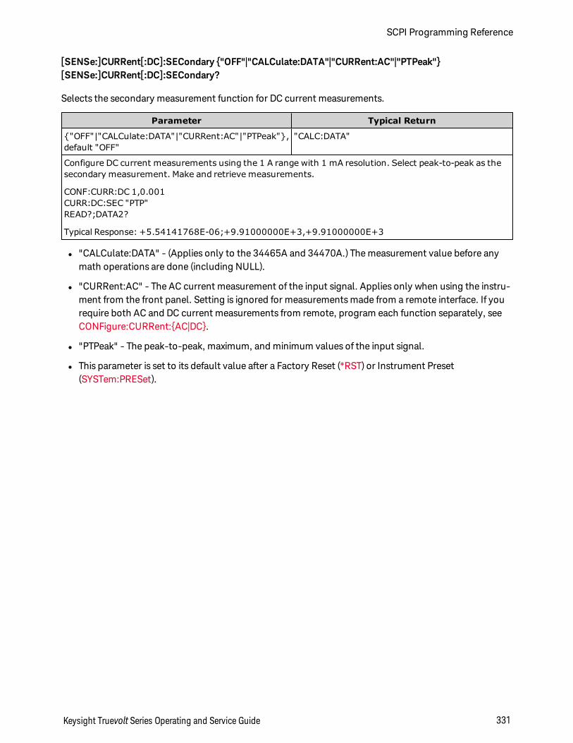
[SENSe:]CURRent[:DC]:SECondary "OFF"|"CALCulate:DATA"|"CURRent:AC"|"PTPeak"[SENSe:]CURRent[:DC]:SECondary?
Selects the secondary measurement function for DC current measurements.
Parameter Typical Return
"OFF"|"CALCulate:DATA"|"CURRent:AC"|"PTPeak",default "OFF"
"CALC:DATA"
Configure DC current measurements using the 1 A range with 1 mA resolution. Select peak-to-peak as thesecondary measurement. Make and retrieve measurements.
CONF:CURR:DC 1,0.001CURR:DC:SEC "PTP"READ?;DATA2?
Typical Response: +5.54141768E-06;+9.91000000E+3,+9.91000000E+3
l "CALCulate:DATA" - (Applies only to the 34465A and 34470A.) The measurement value before anymath operations are done (including NULL).
l "CURRent:AC" - The AC current measurement of the input signal. Applies only when using the instru-ment from the front panel. Setting is ignored for measurements made from a remote interface. If yourequire both AC and DC current measurements from remote, program each function separately, seeCONFigure:CURRent:AC|DC.
l "PTPeak" - The peak-to-peak, maximum, and minimum values of the input signal.
l This parameter is set to its default value after a Factory Reset (*RST) or Instrument Preset(SYSTem:PRESet).
Keysight Truevolt Series Operating and Service Guide 331
SCPI Programming Reference
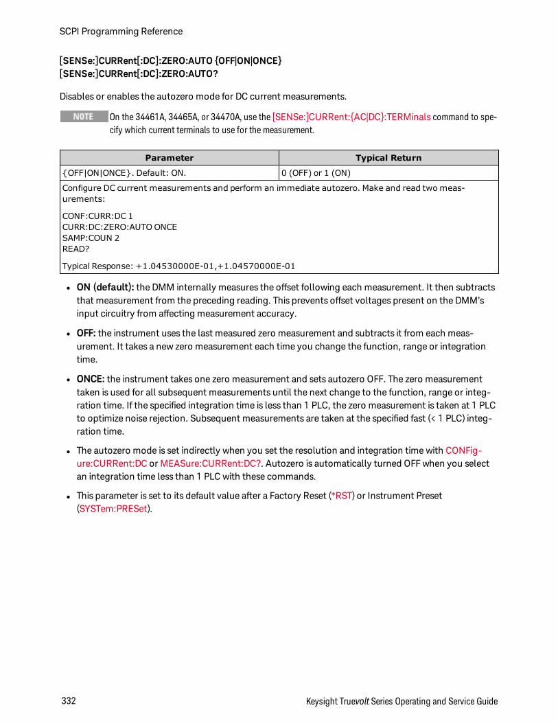
[SENSe:]CURRent[:DC]:ZERO:AUTO OFF|ON|ONCE[SENSe:]CURRent[:DC]:ZERO:AUTO?
Disables or enables the autozero mode for DC current measurements.
On the 34461A, 34465A, or 34470A, use the [SENSe:]CURRent:AC|DC:TERMinals command to spe-cify which current terminals to use for the measurement.
Parameter Typical Return
OFF|ON|ONCE. Default: ON. 0 (OFF) or 1 (ON)
Configure DC current measurements and perform an immediate autozero. Make and read two meas-urements:
CONF:CURR:DC 1CURR:DC:ZERO:AUTO ONCESAMP:COUN 2READ?
Typical Response: +1.04530000E-01,+1.04570000E-01
l ON (default): the DMM internally measures the offset following each measurement. It then subtractsthat measurement from the preceding reading. This prevents offset voltages present on the DMM’sinput circuitry from affecting measurement accuracy.
l OFF: the instrument uses the last measured zero measurement and subtracts it from each meas-urement. It takes a new zero measurement each time you change the function, range or integrationtime.
l ONCE: the instrument takes one zero measurement and sets autozero OFF. The zero measurementtaken is used for all subsequent measurements until the next change to the function, range or integ-ration time. If the specified integration time is less than 1 PLC, the zero measurement is taken at 1 PLCto optimize noise rejection. Subsequent measurements are taken at the specified fast (< 1 PLC) integ-ration time.
l The autozero mode is set indirectly when you set the resolution and integration time with CONFig-ure:CURRent:DC or MEASure:CURRent:DC?. Autozero is automatically turned OFF when you selectan integration time less than 1 PLC with these commands.
l This parameter is set to its default value after a Factory Reset (*RST) or Instrument Preset(SYSTem:PRESet).
SCPI Programming Reference
332 Keysight Truevolt Series Operating and Service Guide
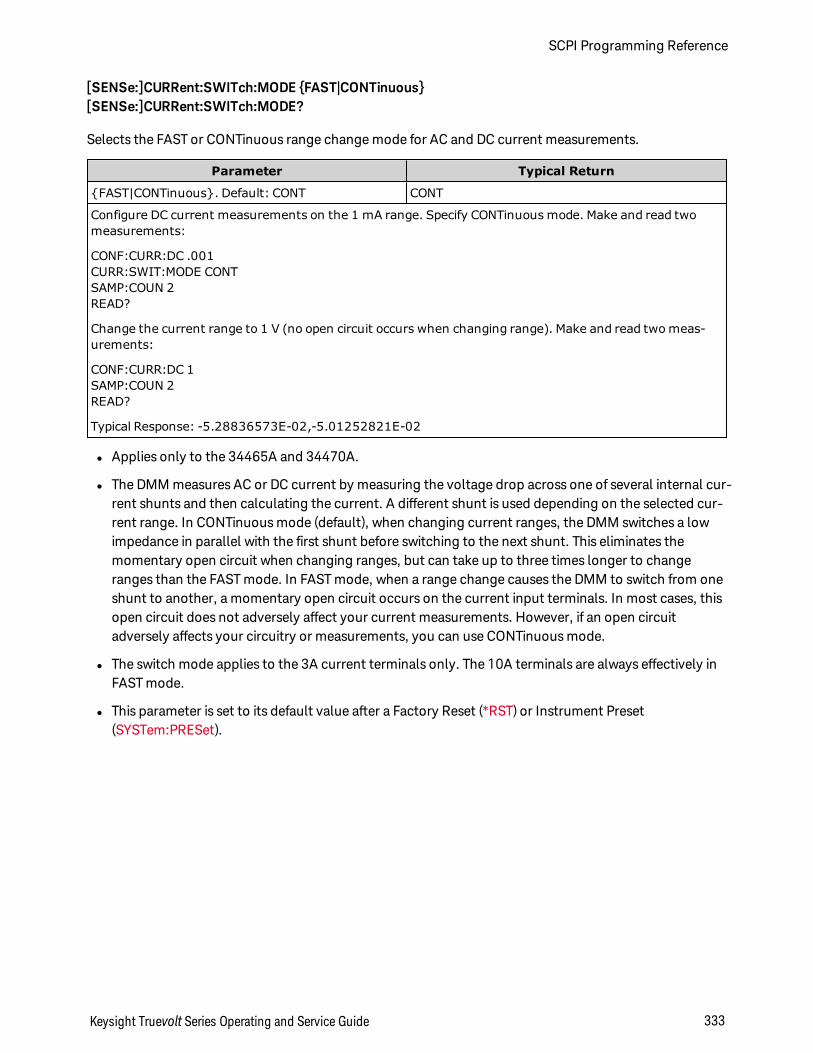
[SENSe:]CURRent:SWITch:MODE FAST|CONTinuous[SENSe:]CURRent:SWITch:MODE?
Selects the FAST or CONTinuous range change mode for AC and DC current measurements.
Parameter Typical Return
FAST|CONTinuous. Default: CONT CONT
Configure DC current measurements on the 1 mA range. Specify CONTinuous mode. Make and read twomeasurements:
CONF:CURR:DC .001CURR:SWIT:MODE CONTSAMP:COUN 2READ?
Change the current range to 1 V (no open circuit occurs when changing range). Make and read two meas-urements:
CONF:CURR:DC 1SAMP:COUN 2READ?
Typical Response: -5.28836573E-02,-5.01252821E-02
l Applies only to the 34465A and 34470A.
l The DMM measures AC or DC current by measuring the voltage drop across one of several internal cur-rent shunts and then calculating the current. A different shunt is used depending on the selected cur-rent range. In CONTinuous mode (default), when changing current ranges, the DMM switches a lowimpedance in parallel with the first shunt before switching to the next shunt. This eliminates themomentary open circuit when changing ranges, but can take up to three times longer to changeranges than the FAST mode. In FAST mode, when a range change causes the DMM to switch from oneshunt to another, a momentary open circuit occurs on the current input terminals. In most cases, thisopen circuit does not adversely affect your current measurements. However, if an open circuitadversely affects your circuitry or measurements, you can use CONTinuous mode.
l The switch mode applies to the 3A current terminals only. The 10A terminals are always effectively inFAST mode.
l This parameter is set to its default value after a Factory Reset (*RST) or Instrument Preset(SYSTem:PRESet).
Keysight Truevolt Series Operating and Service Guide 333
SCPI Programming Reference
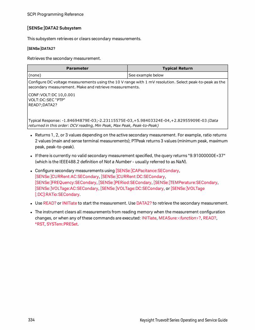
[SENSe:]DATA2 Subsystem
This subsystem retrieves or clears secondary measurements.
[SENSe:]DATA2?
Retrieves the secondary measurement.
Parameter Typical Return
(none) See example below
Configure DC voltage measurements using the 10 V range with 1 mV resolution. Select peak-to-peak as thesecondary measurement. Make and retrieve measurements.
CONF:VOLT:DC 10,0.001VOLT:DC:SEC "PTP"READ?;DATA2?
Typical Response: -1.84694879E-03;-2.23115575E-03,+5.98403324E-04,+2.82955909E-03 (Datareturned in this order: DCV reading, Min Peak, Max Peak, Peak-to-Peak)
l Returns 1, 2, or 3 values depending on the active secondary measurement. For example, ratio returns2 values (main and sense terminal measurements); PTPeak returns 3 values (minimum peak, maximumpeak, peak-to-peak).
l If there is currently no valid secondary measurement specified, the query returns "9.91000000E+37"(which is the IEEE488.2 definition ofNot a Number - usually referred to asNaN).
l Configure secondary measurements using [SENSe:]CAPacitance:SECondary,[SENSe:]CURRent:AC:SECondary, [SENSe:]CURRent:DC:SECondary,[SENSe:]FREQuency:SECondary, [SENSe:]PERiod:SECondary, [SENSe:]TEMPerature:SECondary,[SENSe:]VOLTage:AC:SECondary, [SENSe:]VOLTage:DC:SECondary, or [SENSe:]VOLTage[:DC]:RATio:SECondary.
l Use READ? or INITiate to start the measurement. Use DATA2? to retrieve the secondary measurement.
l The instrument clears all measurements from reading memory when the measurement configurationchanges, or when any of these commands are executed: INITiate, MEASure:<function>?, READ?,*RST, SYSTem:PRESet.
SCPI Programming Reference
334 Keysight Truevolt Series Operating and Service Guide
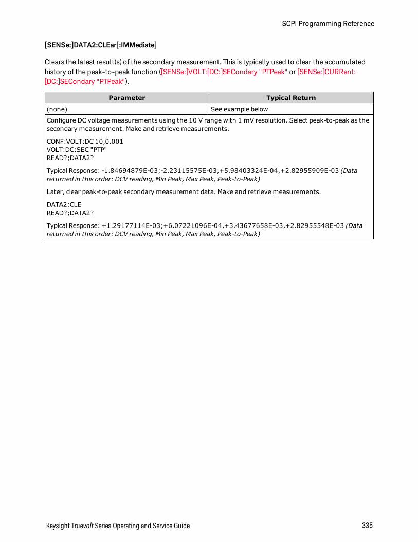
[SENSe:]DATA2:CLEar[:IMMediate]
Clears the latest result(s) of the secondary measurement. This is typically used to clear the accumulatedhistory of the peak-to-peak function ([SENSe:]VOLT:[DC:]SECondary "PTPeak" or [SENSe:]CURRent:[DC:]SECondary "PTPeak").
Parameter Typical Return
(none) See example below
Configure DC voltage measurements using the 10 V range with 1 mV resolution. Select peak-to-peak as thesecondary measurement. Make and retrieve measurements.
CONF:VOLT:DC 10,0.001VOLT:DC:SEC "PTP"READ?;DATA2?
Typical Response: -1.84694879E-03;-2.23115575E-03,+5.98403324E-04,+2.82955909E-03 (Datareturned in this order: DCV reading, Min Peak, Max Peak, Peak-to-Peak)
Later, clear peak-to-peak secondary measurement data. Make and retrieve measurements.
DATA2:CLEREAD?;DATA2?
Typical Response: +1.29177114E-03;+6.07221096E-04,+3.43677658E-03,+2.82955548E-03 (Datareturned in this order: DCV reading, Min Peak, Max Peak, Peak-to-Peak)
Keysight Truevolt Series Operating and Service Guide 335
SCPI Programming Reference
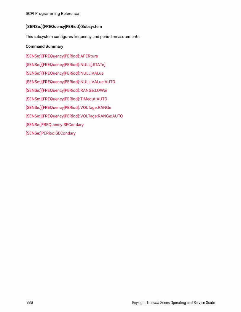
[SENSe:]FREQuency|PERiod Subsystem
This subsystem configures frequency and period measurements.
Command Summary
[SENSe:]FREQuency|PERiod:APERture
[SENSe:]FREQuency|PERiod:NULL[:STATe]
[SENSe:]FREQuency|PERiod:NULL:VALue
[SENSe:]FREQuency|PERiod:NULL:VALue:AUTO
[SENSe:]FREQuency|PERiod:RANGe:LOWer
[SENSe:]FREQuency|PERiod:TIMeout:AUTO
[SENSe:]FREQuency|PERiod:VOLTage:RANGe
[SENSe:]FREQuency|PERiod:VOLTage:RANGe:AUTO
[SENSe:]FREQuency:SECondary
[SENSe:]PERiod:SECondary
SCPI Programming Reference
336 Keysight Truevolt Series Operating and Service Guide
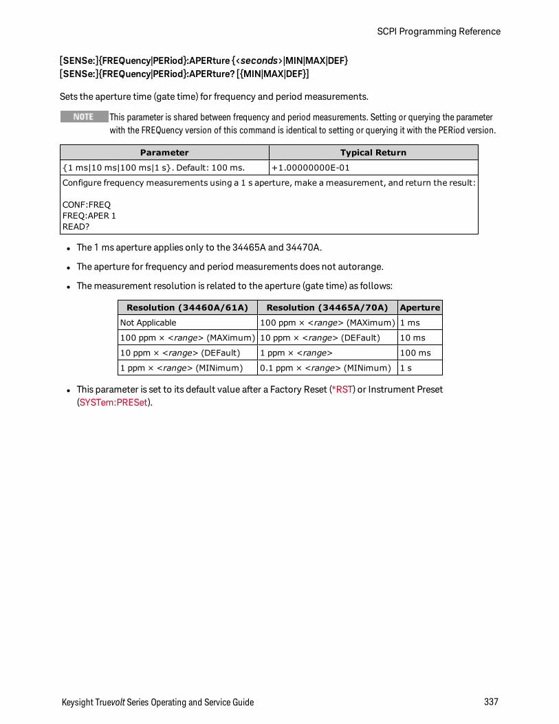
[SENSe:]FREQuency|PERiod:APERture <seconds>|MIN|MAX|DEF[SENSe:]FREQuency|PERiod:APERture? [MIN|MAX|DEF]
Sets the aperture time (gate time) for frequency and period measurements.
This parameter is shared between frequency and period measurements. Setting or querying the parameterwith the FREQuency version of this command is identical to setting or querying it with the PERiod version.
Parameter Typical Return
1 ms|10 ms|100 ms|1 s. Default: 100 ms. +1.00000000E-01
Configure frequency measurements using a 1 s aperture, make a measurement, and return the result:
CONF:FREQFREQ:APER 1READ?
l The 1 ms aperture applies only to the 34465A and 34470A.
l The aperture for frequency and period measurements does not autorange.
l The measurement resolution is related to the aperture (gate time) as follows:
Resolution (34460A/61A) Resolution (34465A/70A) Aperture
Not Applicable 100 ppm × <range> (MAXimum) 1 ms
100 ppm × <range> (MAXimum) 10 ppm × <range> (DEFault) 10 ms
10 ppm × <range> (DEFault) 1 ppm × <range> 100 ms
1 ppm × <range> (MINimum) 0.1 ppm × <range> (MINimum) 1 s
l This parameter is set to its default value after a Factory Reset (*RST) or Instrument Preset(SYSTem:PRESet).
Keysight Truevolt Series Operating and Service Guide 337
SCPI Programming Reference
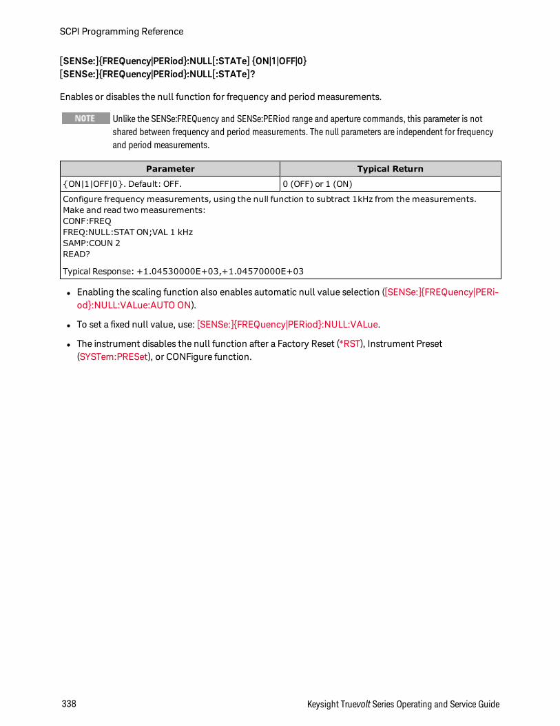
[SENSe:]FREQuency|PERiod:NULL[:STATe] ON|1|OFF|0[SENSe:]FREQuency|PERiod:NULL[:STATe]?
Enables or disables the null function for frequency and period measurements.
Unlike the SENSe:FREQuency and SENSe:PERiod range and aperture commands, this parameter is notshared between frequency and period measurements. The null parameters are independent for frequencyand period measurements.
Parameter Typical Return
ON|1|OFF|0. Default: OFF. 0 (OFF) or 1 (ON)
Configure frequency measurements, using the null function to subtract 1kHz from the measurements.Make and read two measurements:CONF:FREQFREQ:NULL:STAT ON;VAL 1 kHzSAMP:COUN 2READ?
Typical Response: +1.04530000E+03,+1.04570000E+03
l Enabling the scaling function also enables automatic null value selection ([SENSe:]FREQuency|PERi-od:NULL:VALue:AUTO ON).
l To set a fixed null value, use: [SENSe:]FREQuency|PERiod:NULL:VALue.
l The instrument disables the null function after a Factory Reset (*RST), Instrument Preset(SYSTem:PRESet), or CONFigure function.
SCPI Programming Reference
338 Keysight Truevolt Series Operating and Service Guide
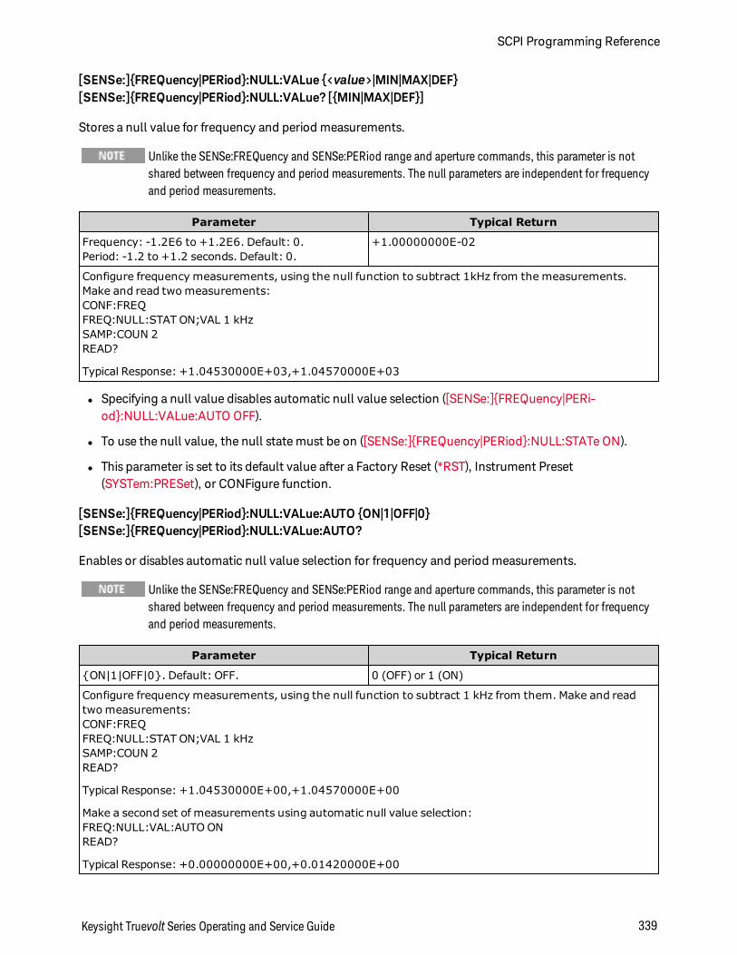
[SENSe:]FREQuency|PERiod:NULL:VALue <value>|MIN|MAX|DEF[SENSe:]FREQuency|PERiod:NULL:VALue? [MIN|MAX|DEF]
Stores a null value for frequency and period measurements.
Unlike the SENSe:FREQuency and SENSe:PERiod range and aperture commands, this parameter is notshared between frequency and period measurements. The null parameters are independent for frequencyand period measurements.
Parameter Typical Return
Frequency: -1.2E6 to +1.2E6. Default: 0.Period: -1.2 to +1.2 seconds. Default: 0.
+1.00000000E-02
Configure frequency measurements, using the null function to subtract 1kHz from the measurements.Make and read two measurements:CONF:FREQFREQ:NULL:STAT ON;VAL 1 kHzSAMP:COUN 2READ?
Typical Response: +1.04530000E+03,+1.04570000E+03
l Specifying a null value disables automatic null value selection ([SENSe:]FREQuency|PERi-od:NULL:VALue:AUTO OFF).
l To use the null value, the null state must be on ([SENSe:]FREQuency|PERiod:NULL:STATe ON).
l This parameter is set to its default value after a Factory Reset (*RST), Instrument Preset(SYSTem:PRESet), or CONFigure function.
[SENSe:]FREQuency|PERiod:NULL:VALue:AUTO ON|1|OFF|0[SENSe:]FREQuency|PERiod:NULL:VALue:AUTO?
Enables or disables automatic null value selection for frequency and period measurements.
Unlike the SENSe:FREQuency and SENSe:PERiod range and aperture commands, this parameter is notshared between frequency and period measurements. The null parameters are independent for frequencyand period measurements.
Parameter Typical Return
ON|1|OFF|0. Default: OFF. 0 (OFF) or 1 (ON)
Configure frequency measurements, using the null function to subtract 1 kHz from them. Make and readtwo measurements:CONF:FREQFREQ:NULL:STAT ON;VAL 1 kHzSAMP:COUN 2READ?
Typical Response: +1.04530000E+00,+1.04570000E+00
Make a second set of measurements using automatic null value selection:FREQ:NULL:VAL:AUTO ONREAD?
Typical Response: +0.00000000E+00,+0.01420000E+00
Keysight Truevolt Series Operating and Service Guide 339
SCPI Programming Reference
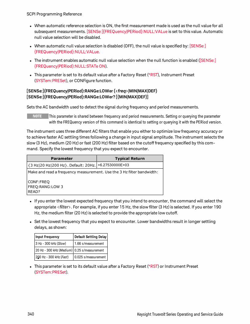
l When automatic reference selection is ON, the first measurement made is used as the null value for allsubsequent measurements. [SENSe:]FREQuency|PERiod:NULL:VALue is set to this value. Automaticnull value selection will be disabled.
l When automatic null value selection is disabled (OFF), the null value is specified by: [SENSe:]FREQuency|PERiod:NULL:VALue.
l The instrument enables automatic null value selection when the null function is enabled ([SENSe:]FREQuency|PERiod:NULL:STATe ON).
l This parameter is set to its default value after a Factory Reset (*RST), Instrument Preset(SYSTem:PRESet), or CONFigure function.
[SENSe:]FREQuency|PERiod:RANGe:LOWer <freq>|MIN|MAX|DEF[SENSe:]FREQuency|PERiod:RANGe:LOWer? [MIN|MAX|DEF]
Sets the AC bandwidth used to detect the signal during frequency and period measurements.
This parameter is shared between frequency and period measurements. Setting or querying the parameterwith the FREQuency version of this command is identical to setting or querying it with the PERiod version.
The instrument uses three different AC filters that enable you either to optimize low frequency accuracy orto achieve faster AC settling times following a change in input signal amplitude. The instrument selects theslow (3 Hz), medium (20 Hz) or fast (200 Hz) filter based on the cutoff frequency specified by this com-mand. Specify the lowest frequency that you expect to encounter.
Parameter Typical Return
3 Hz|20 Hz|200 Hz. Default: 20Hz. +6.27530000E+03
Make and read a frequency measurement. Use the 3 Hz filter bandwidth:
CONF:FREQFREQ:RANG:LOW 3READ?
l If you enter the lowest expected frequency that you intend to encounter, the command will select theappropriate <filter>. For example, if you enter 15 Hz, the slow filter (3 Hz) is selected. If you enter 190Hz, the medium filter (20 Hz) is selected to provide the appropriate low cutoff.
l Set the lowest frequency that you expect to encounter. Lower bandwidths result in longer settlingdelays, as shown:
l
Input Frequency Default Settling Delay
3 Hz - 300 kHz (Slow) 1.66 s/measurement
20 Hz - 300 kHz (Medium) 0.25 s/measurement
200 Hz - 300 kHz (Fast) 0.025 s/measurement
l This parameter is set to its default value after a Factory Reset (*RST) or Instrument Preset(SYSTem:PRESet).
SCPI Programming Reference
340 Keysight Truevolt Series Operating and Service Guide
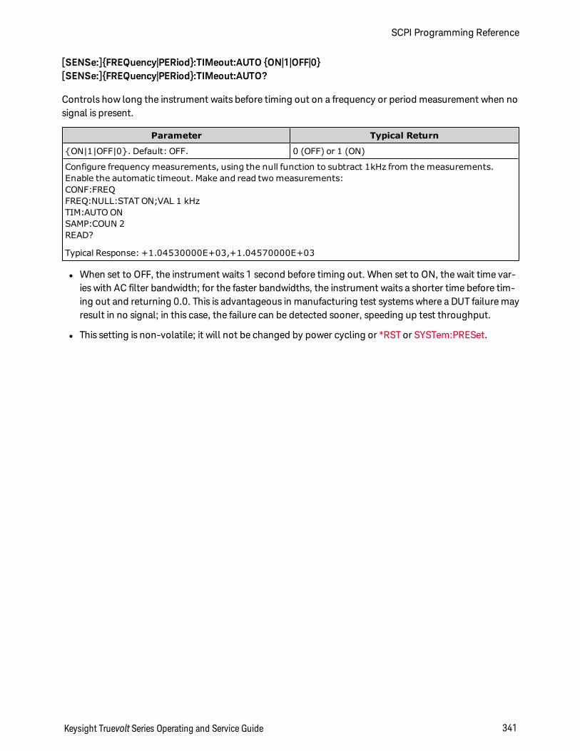
[SENSe:]FREQuency|PERiod:TIMeout:AUTO ON|1|OFF|0[SENSe:]FREQuency|PERiod:TIMeout:AUTO?
Controls how long the instrument waits before timing out on a frequency or period measurement when nosignal is present.
Parameter Typical Return
ON|1|OFF|0. Default: OFF. 0 (OFF) or 1 (ON)
Configure frequency measurements, using the null function to subtract 1kHz from the measurements.Enable the automatic timeout. Make and read two measurements:CONF:FREQFREQ:NULL:STAT ON;VAL 1 kHzTIM:AUTO ONSAMP:COUN 2READ?
Typical Response: +1.04530000E+03,+1.04570000E+03
l When set to OFF, the instrument waits 1 second before timing out. When set to ON, the wait time var-ies with AC filter bandwidth; for the faster bandwidths, the instrument waits a shorter time before tim-ing out and returning 0.0. This is advantageous in manufacturing test systems where a DUT failure mayresult in no signal; in this case, the failure can be detected sooner, speeding up test throughput.
l This setting is non-volatile; it will not be changed by power cycling or *RST or SYSTem:PRESet.
Keysight Truevolt Series Operating and Service Guide 341
SCPI Programming Reference
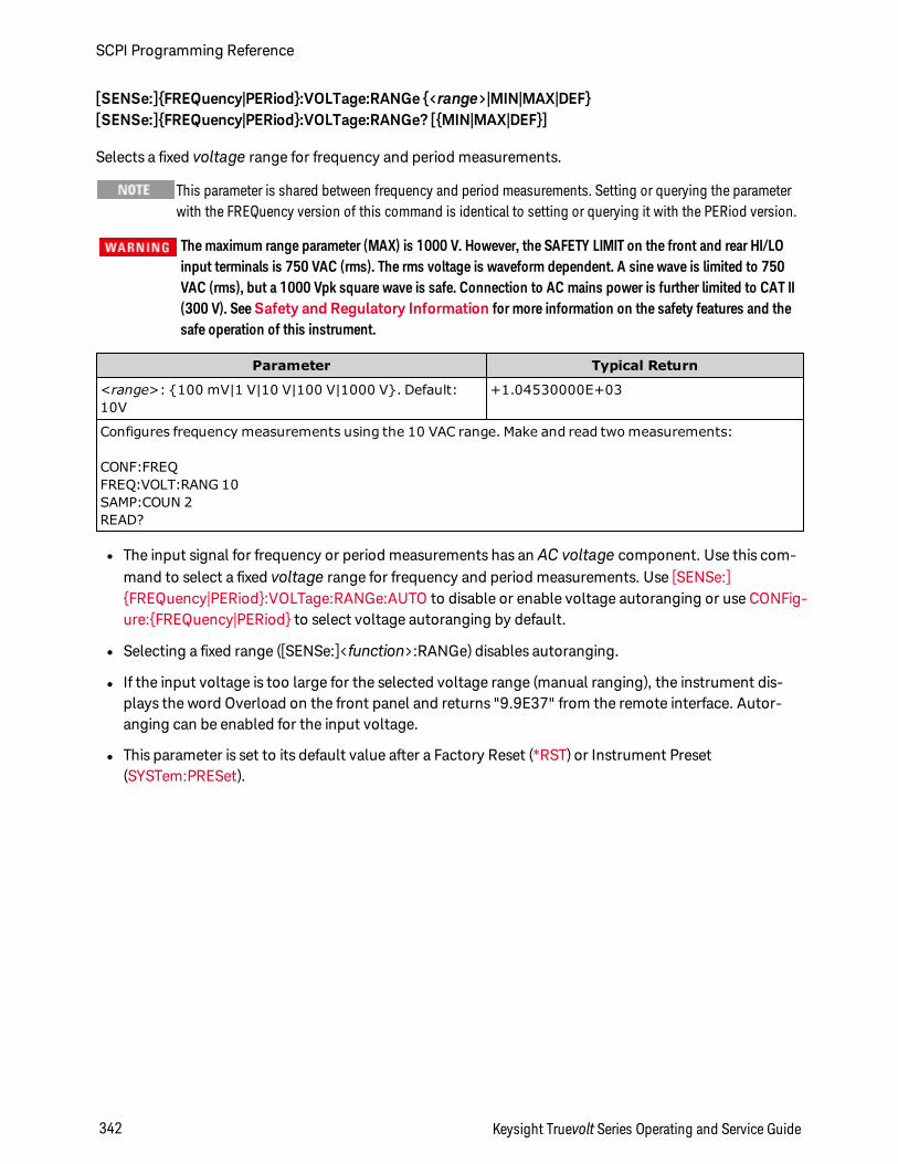
[SENSe:]FREQuency|PERiod:VOLTage:RANGe <range>|MIN|MAX|DEF[SENSe:]FREQuency|PERiod:VOLTage:RANGe? [MIN|MAX|DEF]
Selects a fixed voltage range for frequency and period measurements.
This parameter is shared between frequency and period measurements. Setting or querying the parameterwith the FREQuency version of this command is identical to setting or querying it with the PERiod version.
The maximum range parameter (MAX) is 1000 V. However, the SAFETY LIMIT on the front and rear HI/LOinput terminals is 750 VAC (rms). The rms voltage is waveform dependent. A sine wave is limited to 750VAC (rms), but a 1000 Vpk square wave is safe. Connection to AC mains power is further limited to CAT II(300 V). SeeSafety and Regulatory Information for more information on the safety features and thesafe operation of this instrument.
Parameter Typical Return
<range>: 100 mV|1 V|10 V|100 V|1000 V. Default:10V
+1.04530000E+03
Configures frequency measurements using the 10 VAC range. Make and read two measurements:
CONF:FREQFREQ:VOLT:RANG 10SAMP:COUN 2READ?
l The input signal for frequency or period measurements has an AC voltage component. Use this com-mand to select a fixed voltage range for frequency and period measurements. Use [SENSe:]FREQuency|PERiod:VOLTage:RANGe:AUTO to disable or enable voltage autoranging or use CONFig-ure:FREQuency|PERiod to select voltage autoranging by default.
l Selecting a fixed range ([SENSe:]<function>:RANGe) disables autoranging.
l If the input voltage is too large for the selected voltage range (manual ranging), the instrument dis-plays the word Overload on the front panel and returns "9.9E37" from the remote interface. Autor-anging can be enabled for the input voltage.
l This parameter is set to its default value after a Factory Reset (*RST) or Instrument Preset(SYSTem:PRESet).
SCPI Programming Reference
342 Keysight Truevolt Series Operating and Service Guide
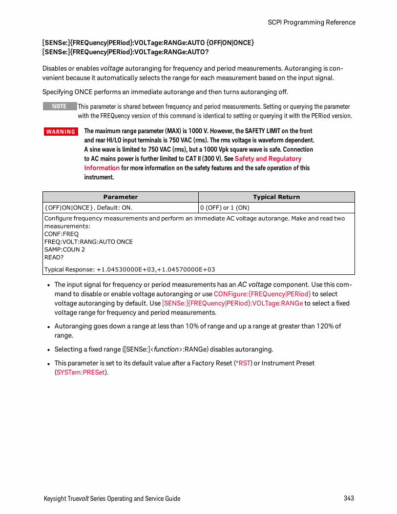
[SENSe:]FREQuency|PERiod:VOLTage:RANGe:AUTO OFF|ON|ONCE[SENSe:]FREQuency|PERiod:VOLTage:RANGe:AUTO?
Disables or enables voltage autoranging for frequency and period measurements. Autoranging is con-venient because it automatically selects the range for each measurement based on the input signal.
Specifying ONCE performs an immediate autorange and then turns autoranging off.
This parameter is shared between frequency and period measurements. Setting or querying the parameterwith the FREQuency version of this command is identical to setting or querying it with the PERiod version.
The maximum range parameter (MAX) is 1000 V. However, the SAFETY LIMIT on the frontand rear HI/LO input terminals is 750 VAC (rms). The rms voltage is waveform dependent.A sine wave is limited to 750 VAC (rms), but a 1000 Vpk square wave is safe. Connectionto AC mains power is further limited to CAT II (300 V). SeeSafety and RegulatoryInformation for more information on the safety features and the safe operation of thisinstrument.
Parameter Typical Return
OFF|ON|ONCE. Default: ON. 0 (OFF) or 1 (ON)
Configure frequency measurements and perform an immediate AC voltage autorange. Make and read twomeasurements:CONF:FREQFREQ:VOLT:RANG:AUTO ONCESAMP:COUN 2READ?
Typical Response: +1.04530000E+03,+1.04570000E+03
l The input signal for frequency or period measurements has an AC voltage component. Use this com-mand to disable or enable voltage autoranging or use CONFigure:FREQuency|PERiod to selectvoltage autoranging by default. Use [SENSe:]FREQuency|PERiod:VOLTage:RANGe to select a fixedvoltage range for frequency and period measurements.
l Autoranging goes down a range at less than 10% of range and up a range at greater than 120% ofrange.
l Selecting a fixed range ([SENSe:]<function>:RANGe) disables autoranging.
l This parameter is set to its default value after a Factory Reset (*RST) or Instrument Preset(SYSTem:PRESet).
Keysight Truevolt Series Operating and Service Guide 343
SCPI Programming Reference
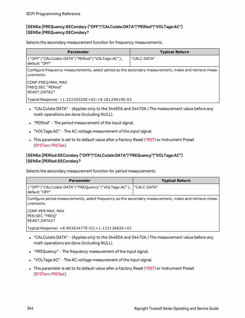
[SENSe:]FREQuency:SECondary "OFF"|"CALCulate:DATA"|"PERiod"|"VOLTage:AC"[SENSe:]FREQuency:SECondary?
Selects the secondary measurement function for frequency measurements.
Parameter Typical Return
"OFF"|"CALCulate:DATA"|"PERiod"|"VOLTage:AC",default "OFF"
"CALC:DATA"
Configure frequency measurements, select period as the secondary measurement, make and retrieve meas-urements.
CONF:FREQ MAX, MAXFREQ:SEC "PERiod"READ?;DATA2?
Typical Response: +1.22230020E+02;+8.18129619E-03
l "CALCulate:DATA" - (Applies only to the 34465A and 34470A.) The measurement value before anymath operations are done (including NULL).
l “PERiod” - The period measurement of the input signal.
l "VOLTage:AC" - The AC voltage measurement of the input signal.
l This parameter is set to its default value after a Factory Reset (*RST) or Instrument Preset(SYSTem:PRESet).
[SENSe:]PERiod:SECondary "OFF"|"CALCulate:DATA"|"FREQuency"|"VOLTage:AC"[SENSe:]PERiod:SECondary?
Selects the secondary measurement function for period measurements.
Parameter Typical Return
"OFF"|"CALCulate:DATA"|"FREQuency"|"VOLTage:AC",default "OFF"
"CALC:DATA"
Configure period measurements, select frequency as the secondary measurement, make and retrieve meas-urements.
CONF:PER MAX, MAXPER:SEC "FREQ"READ?;DATA2?
Typical Response: +8.90363477E-03;+1.12313682E+02
l "CALCulate:DATA" - (Applies only to the 34465A and 34470A.) The measurement value before anymath operations are done (including NULL).
l “FREQuency” - The frequency measurement of the input signal.
l "VOLTage:AC" - The AC voltage measurement of the input signal.
l This parameter is set to its default value after a Factory Reset (*RST) or Instrument Preset(SYSTem:PRESet).
SCPI Programming Reference
344 Keysight Truevolt Series Operating and Service Guide
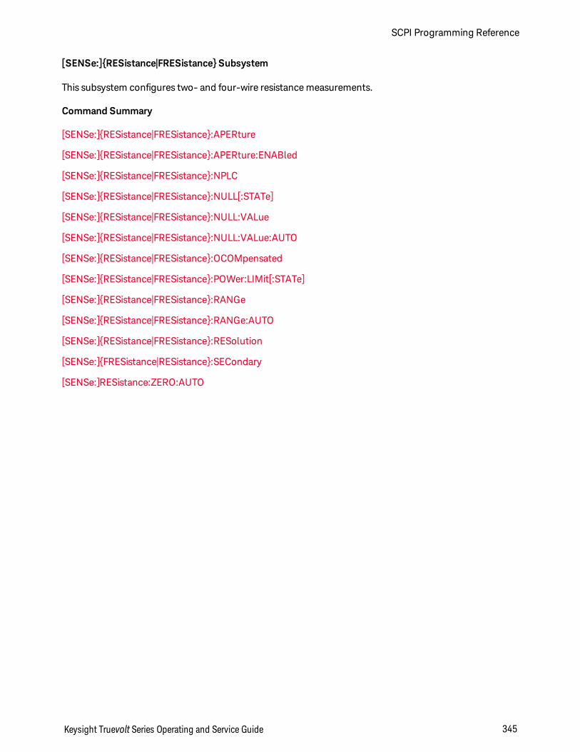
[SENSe:]RESistance|FRESistance Subsystem
This subsystem configures two- and four-wire resistance measurements.
Command Summary
[SENSe:]RESistance|FRESistance:APERture
[SENSe:]RESistance|FRESistance:APERture:ENABled
[SENSe:]RESistance|FRESistance:NPLC
[SENSe:]RESistance|FRESistance:NULL[:STATe]
[SENSe:]RESistance|FRESistance:NULL:VALue
[SENSe:]RESistance|FRESistance:NULL:VALue:AUTO
[SENSe:]RESistance|FRESistance:OCOMpensated
[SENSe:]RESistance|FRESistance:POWer:LIMit[:STATe]
[SENSe:]RESistance|FRESistance:RANGe
[SENSe:]RESistance|FRESistance:RANGe:AUTO
[SENSe:]RESistance|FRESistance:RESolution
[SENSe:]FRESistance|RESistance:SECondary
[SENSe:]RESistance:ZERO:AUTO
Keysight Truevolt Series Operating and Service Guide 345
SCPI Programming Reference
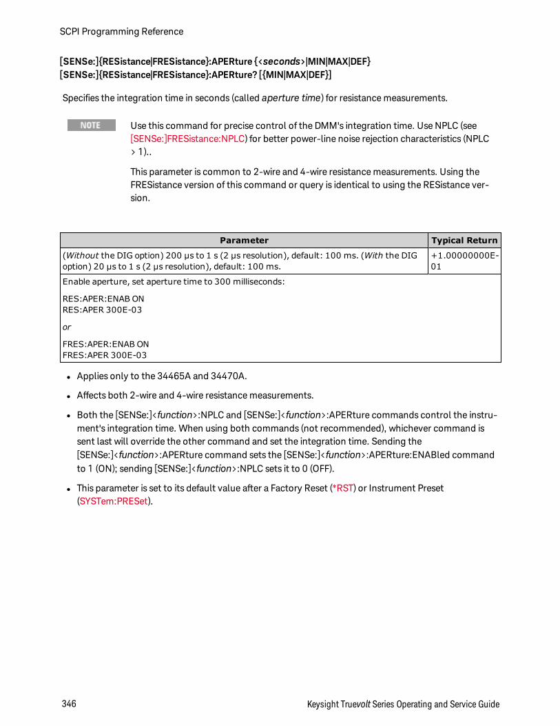
[SENSe:]RESistance|FRESistance:APERture <seconds>|MIN|MAX|DEF[SENSe:]RESistance|FRESistance:APERture? [MIN|MAX|DEF]
Specifies the integration time in seconds (called aperture time) for resistance measurements.
Use this command for precise control of the DMM's integration time. Use NPLC (see[SENSe:]FRESistance:NPLC) for better power-line noise rejection characteristics (NPLC> 1)..
This parameter is common to 2-wire and 4-wire resistance measurements. Using theFRESistance version of this command or query is identical to using the RESistance ver-sion.
Parameter Typical Return
(Without the DIG option) 200 µs to 1 s (2 µs resolution), default: 100 ms. (With the DIGoption) 20 µs to 1 s (2 µs resolution), default: 100 ms.
+1.00000000E-01
Enable aperture, set aperture time to 300 milliseconds:
RES:APER:ENAB ONRES:APER 300E-03
or
FRES:APER:ENAB ONFRES:APER 300E-03
l Applies only to the 34465A and 34470A.
l Affects both 2-wire and 4-wire resistance measurements.
l Both the [SENSe:]<function>:NPLC and [SENSe:]<function>:APERture commands control the instru-ment's integration time. When using both commands (not recommended), whichever command issent last will override the other command and set the integration time. Sending the[SENSe:]<function>:APERture command sets the [SENSe:]<function>:APERture:ENABled commandto 1 (ON); sending [SENSe:]<function>:NPLC sets it to 0 (OFF).
l This parameter is set to its default value after a Factory Reset (*RST) or Instrument Preset(SYSTem:PRESet).
SCPI Programming Reference
346 Keysight Truevolt Series Operating and Service Guide
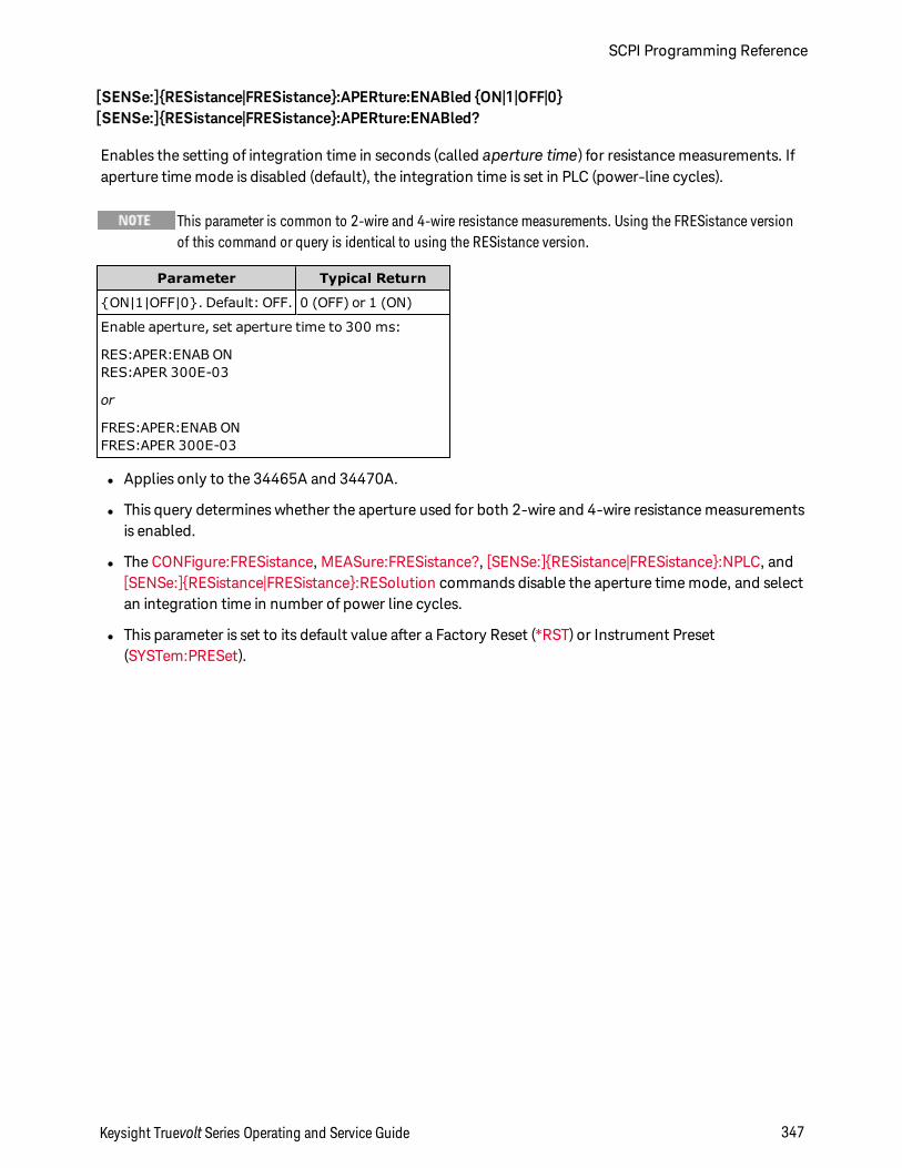
[SENSe:]RESistance|FRESistance:APERture:ENABled ON|1|OFF|0[SENSe:]RESistance|FRESistance:APERture:ENABled?
Enables the setting of integration time in seconds (called aperture time) for resistance measurements. Ifaperture time mode is disabled (default), the integration time is set in PLC (power-line cycles).
This parameter is common to 2-wire and 4-wire resistance measurements. Using the FRESistance versionof this command or query is identical to using the RESistance version.
Parameter Typical Return
ON|1|OFF|0. Default: OFF. 0 (OFF) or 1 (ON)
Enable aperture, set aperture time to 300 ms:
RES:APER:ENAB ONRES:APER 300E-03
or
FRES:APER:ENAB ONFRES:APER 300E-03
l Applies only to the 34465A and 34470A.
l This query determines whether the aperture used for both 2-wire and 4-wire resistance measurementsis enabled.
l The CONFigure:FRESistance, MEASure:FRESistance?, [SENSe:]RESistance|FRESistance:NPLC, and[SENSe:]RESistance|FRESistance:RESolution commands disable the aperture time mode, and selectan integration time in number of power line cycles.
l This parameter is set to its default value after a Factory Reset (*RST) or Instrument Preset(SYSTem:PRESet).
Keysight Truevolt Series Operating and Service Guide 347
SCPI Programming Reference
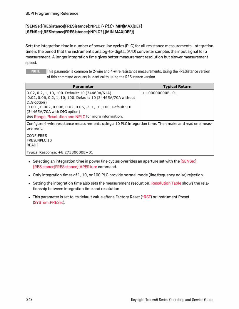
[SENSe:]RESistance|FRESistance:NPLC <PLC>|MIN|MAX|DEF[SENSe:]RESistance|FRESistance:NPLC? [MIN|MAX|DEF]
Sets the integration time in number of power line cycles (PLC) for all resistance measurements. Integrationtime is the period that the instrument's analog-to-digital (A/D) converter samples the input signal for ameasurement. A longer integration time gives better measurement resolution but slower measurementspeed.
This parameter is common to 2-wire and 4-wire resistance measurements. Using the FRESistance versionof this command or query is identical to using the RESistance version.
Parameter Typical Return
0.02, 0.2, 1, 10, 100. Default: 10 (34460A/61A)0.02, 0.06, 0.2, 1, 10, 100. Default: 10 (34465A/70A withoutDIG option)0.001, 0.002, 0.006, 0.02, 0.06, .2, 1, 10, 100. Default: 10(34465A/70A with DIG option)See Range, Resolution and NPLC for more information.
+1.00000000E+01
Configure 4-wire resistance measurements using a 10 PLC integration time. Then make and read one meas-urement:
CONF:FRESFRES:NPLC 10READ?
Typical Response: +6.27530000E+01
l Selecting an integration time in power line cycles overrides an aperture set with the [SENSe:]RESistance|FRESistance:APERture command.
l Only integration times of 1, 10, or 100 PLC provide normal mode (line frequency noise) rejection.
l Setting the integration time also sets the measurement resolution. Resolution Table shows the rela-tionship between integration time and resolution.
l This parameter is set to its default value after a Factory Reset (*RST) or Instrument Preset(SYSTem:PRESet).
SCPI Programming Reference
348 Keysight Truevolt Series Operating and Service Guide
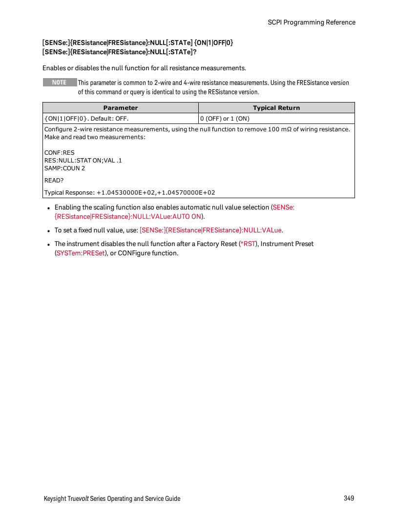
[SENSe:]RESistance|FRESistance:NULL[:STATe] ON|1|OFF|0[SENSe:]RESistance|FRESistance:NULL[:STATe]?
Enables or disables the null function for all resistance measurements.
This parameter is common to 2-wire and 4-wire resistance measurements. Using the FRESistance versionof this command or query is identical to using the RESistance version.
Parameter Typical Return
ON|1|OFF|0. Default: OFF. 0 (OFF) or 1 (ON)
Configure 2-wire resistance measurements, using the null function to remove 100 mΩ of wiring resistance.Make and read two measurements:
CONF:RESRES:NULL:STAT ON;VAL .1SAMP:COUN 2
READ?
Typical Response: +1.04530000E+02,+1.04570000E+02
l Enabling the scaling function also enables automatic null value selection (SENSe:RESistance|FRESistance:NULL:VALue:AUTO ON).
l To set a fixed null value, use: [SENSe:]RESistance|FRESistance:NULL:VALue.
l The instrument disables the null function after a Factory Reset (*RST), Instrument Preset(SYSTem:PRESet), or CONFigure function.
Keysight Truevolt Series Operating and Service Guide 349
SCPI Programming Reference
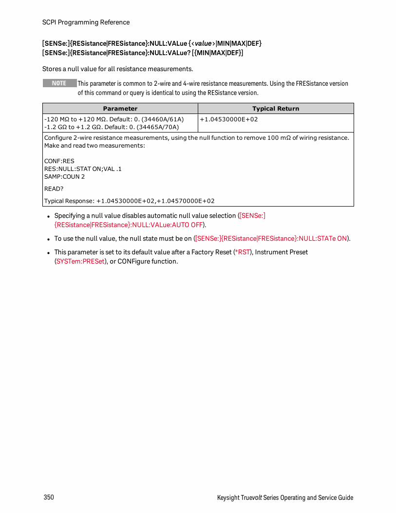
[SENSe:]RESistance|FRESistance:NULL:VALue <value>|MIN|MAX|DEF[SENSe:]RESistance|FRESistance:NULL:VALue? [MIN|MAX|DEF]
Stores a null value for all resistance measurements.
This parameter is common to 2-wire and 4-wire resistance measurements. Using the FRESistance versionof this command or query is identical to using the RESistance version.
Parameter Typical Return
-120 MΩ to +120 MΩ. Default: 0. (34460A/61A)-1.2 GΩ to +1.2 GΩ. Default: 0. (34465A/70A)
+1.04530000E+02
Configure 2-wire resistance measurements, using the null function to remove 100 mΩ of wiring resistance.Make and read two measurements:
CONF:RESRES:NULL:STAT ON;VAL .1SAMP:COUN 2
READ?
Typical Response: +1.04530000E+02,+1.04570000E+02
l Specifying a null value disables automatic null value selection ([SENSe:]RESistance|FRESistance:NULL:VALue:AUTO OFF).
l To use the null value, the null state must be on ([SENSe:]RESistance|FRESistance:NULL:STATe ON).
l This parameter is set to its default value after a Factory Reset (*RST), Instrument Preset(SYSTem:PRESet), or CONFigure function.
SCPI Programming Reference
350 Keysight Truevolt Series Operating and Service Guide
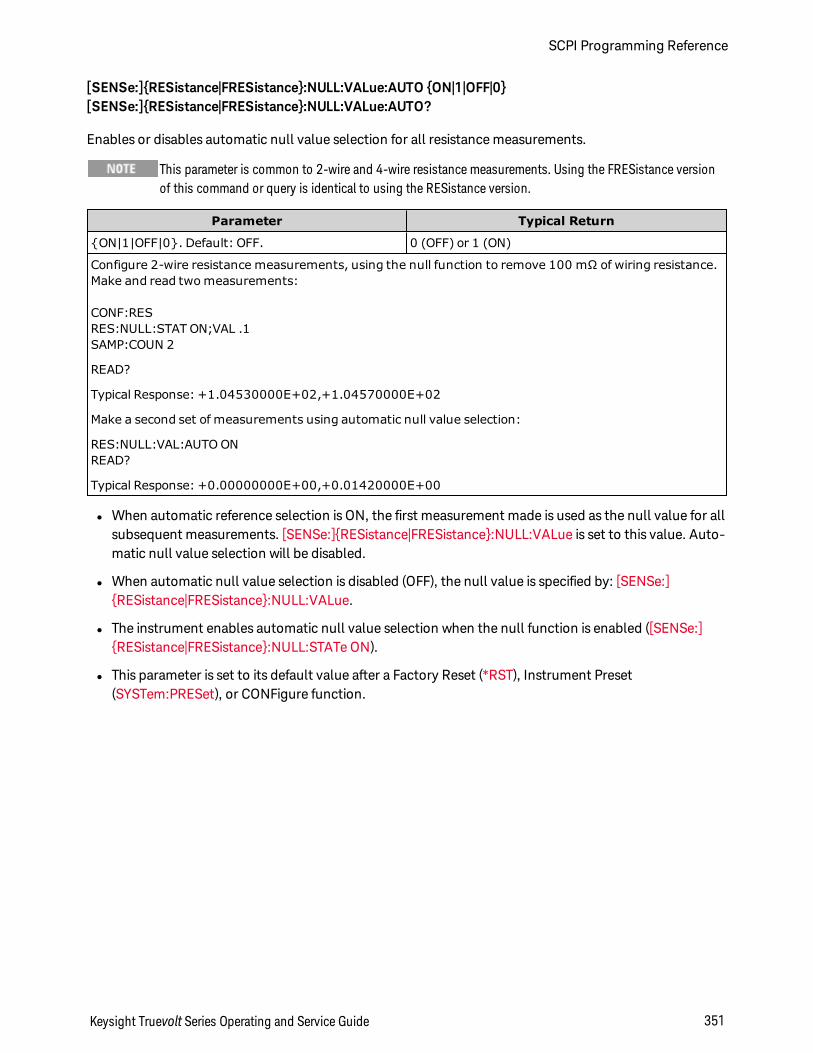
[SENSe:]RESistance|FRESistance:NULL:VALue:AUTO ON|1|OFF|0[SENSe:]RESistance|FRESistance:NULL:VALue:AUTO?
Enables or disables automatic null value selection for all resistance measurements.
This parameter is common to 2-wire and 4-wire resistance measurements. Using the FRESistance versionof this command or query is identical to using the RESistance version.
Parameter Typical Return
ON|1|OFF|0. Default: OFF. 0 (OFF) or 1 (ON)
Configure 2-wire resistance measurements, using the null function to remove 100 mΩ of wiring resistance.Make and read two measurements:
CONF:RESRES:NULL:STAT ON;VAL .1SAMP:COUN 2
READ?
Typical Response: +1.04530000E+02,+1.04570000E+02
Make a second set of measurements using automatic null value selection:
RES:NULL:VAL:AUTO ONREAD?
Typical Response: +0.00000000E+00,+0.01420000E+00
l When automatic reference selection is ON, the first measurement made is used as the null value for allsubsequent measurements. [SENSe:]RESistance|FRESistance:NULL:VALue is set to this value. Auto-matic null value selection will be disabled.
l When automatic null value selection is disabled (OFF), the null value is specified by: [SENSe:]RESistance|FRESistance:NULL:VALue.
l The instrument enables automatic null value selection when the null function is enabled ([SENSe:]RESistance|FRESistance:NULL:STATe ON).
l This parameter is set to its default value after a Factory Reset (*RST), Instrument Preset(SYSTem:PRESet), or CONFigure function.
Keysight Truevolt Series Operating and Service Guide 351
SCPI Programming Reference
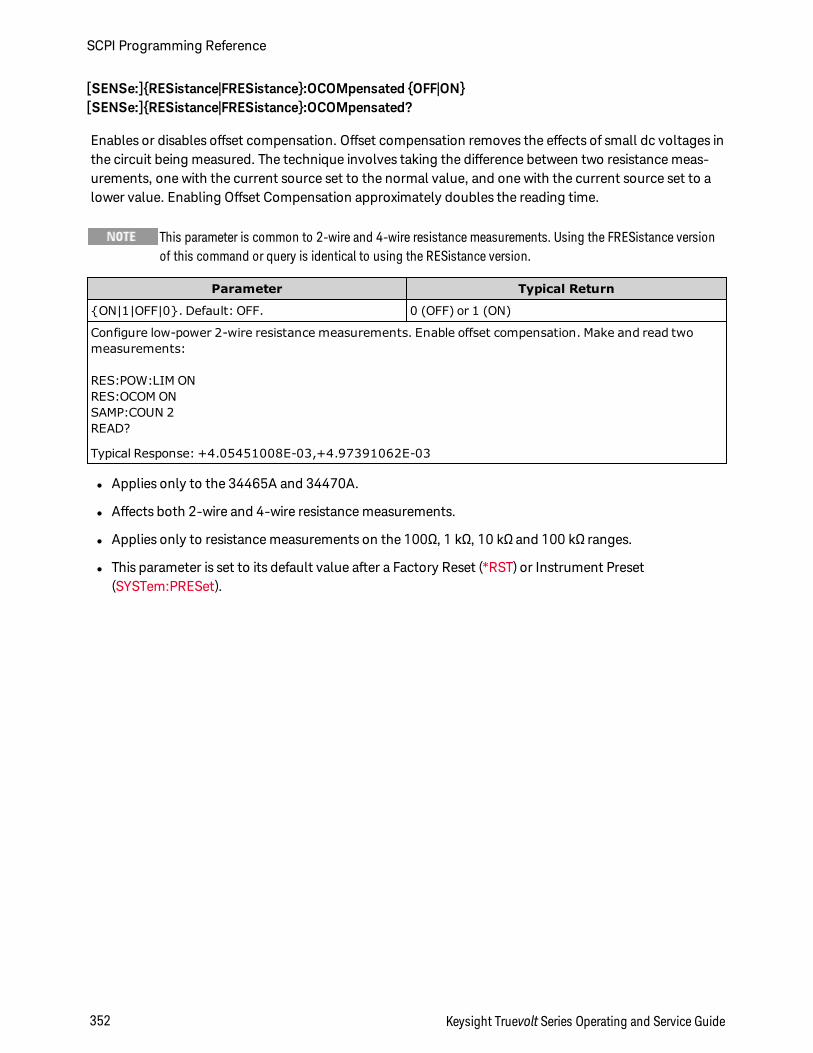
[SENSe:]RESistance|FRESistance:OCOMpensated OFF|ON[SENSe:]RESistance|FRESistance:OCOMpensated?
Enables or disables offset compensation. Offset compensation removes the effects of small dc voltages inthe circuit being measured. The technique involves taking the difference between two resistance meas-urements, one with the current source set to the normal value, and one with the current source set to alower value. Enabling Offset Compensation approximately doubles the reading time.
This parameter is common to 2-wire and 4-wire resistance measurements. Using the FRESistance versionof this command or query is identical to using the RESistance version.
Parameter Typical Return
ON|1|OFF|0. Default: OFF. 0 (OFF) or 1 (ON)
Configure low-power 2-wire resistance measurements. Enable offset compensation. Make and read twomeasurements:
RES:POW:LIM ONRES:OCOM ONSAMP:COUN 2READ?
Typical Response: +4.05451008E-03,+4.97391062E-03
l Applies only to the 34465A and 34470A.
l Affects both 2-wire and 4-wire resistance measurements.
l Applies only to resistance measurements on the 100Ω, 1 kΩ, 10 kΩ and 100 kΩ ranges.
l This parameter is set to its default value after a Factory Reset (*RST) or Instrument Preset(SYSTem:PRESet).
SCPI Programming Reference
352 Keysight Truevolt Series Operating and Service Guide
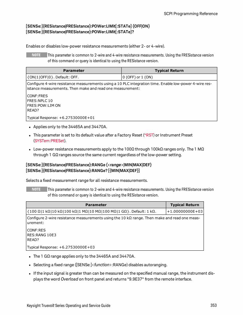
[SENSe:]RESistance|FRESistance:POWer:LIMit[:STATe] OFF|ON[SENSe:]RESistance|FRESistance:POWer:LIMit[:STATe]?
Enables or disables low-power resistance measurements (either 2- or 4-wire).
This parameter is common to 2-wire and 4-wire resistance measurements. Using the FRESistance versionof this command or query is identical to using the RESistance version.
Parameter Typical Return
ON|1|OFF|0. Default: OFF. 0 (OFF) or 1 (ON)
Configure 4-wire resistance measurements using a 10 PLC integration time. Enable low-power 4-wire res-istance measurements. Then make and read one measurement:
CONF:FRESFRES:NPLC 10FRES:POW:LIM ONREAD?
Typical Response: +6.27530000E+01
l Applies only to the 34465A and 34470A.
l This parameter is set to its default value after a Factory Reset (*RST) or Instrument Preset(SYSTem:PRESet).
l Low-power resistance measurements apply to the 100Ω through 100kΩ ranges only. The 1 MΩthrough 1 GΩ ranges source the same current regardless of the low-power setting.
[SENSe:]RESistance|FRESistance:RANGe <range>|MIN|MAX|DEF[SENSe:]RESistance|FRESistance:RANGe? [MIN|MAX|DEF]
Selects a fixed measurement range for all resistance measurements.
This parameter is common to 2-wire and 4-wire resistance measurements. Using the FRESistance versionof this command or query is identical to using the RESistance version.
Parameter Typical Return
100 Ω|1 kΩ|10 kΩ|100 kΩ|1 MΩ|10 MΩ|100 MΩ|1 GΩ. Default: 1 kΩ. +1.00000000E+03
Configure 2-wire resistance measurements using the 10 kΩ range. Then make and read one meas-urement:
CONF:RESRES:RANG 10E3READ?
Typical Response: +6.27530000E+03
l The 1 GΩ range applies only to the 34465A and 34470A.
l Selecting a fixed range ([SENSe:]<function>:RANGe) disables autoranging.
l If the input signal is greater than can be measured on the specified manual range, the instrument dis-plays the word Overload on front panel and returns "9.9E37" from the remote interface.
Keysight Truevolt Series Operating and Service Guide 353
SCPI Programming Reference
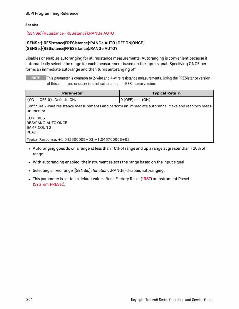
See Also
[SENSe:]RESistance|FRESistance:RANGe:AUTO
[SENSe:]RESistance|FRESistance:RANGe:AUTO OFF|ON|ONCE[SENSe:]RESistance|FRESistance:RANGe:AUTO?
Disables or enables autoranging for all resistance measurements. Autoranging is convenient because itautomatically selects the range for each measurement based on the input signal. Specifying ONCE per-forms an immediate autorange and then turns autoranging off.
This parameter is common to 2-wire and 4-wire resistance measurements. Using the FRESistance versionof this command or query is identical to using the RESistance version.
Parameter Typical Return
ON|1|OFF|0. Default: ON. 0 (OFF) or 1 (ON)
Configure 2-wire resistance measurements and perform an immediate autorange. Make and read two meas-urements:
CONF:RESRES:RANG:AUTO ONCESAMP:COUN 2READ?
Typical Response: +1.04530000E+03,+1.04570000E+03
l Autoranging goes down a range at less than 10% of range and up a range at greater than 120% ofrange.
l With autoranging enabled, the instrument selects the range based on the input signal.
l Selecting a fixed range ([SENSe:]<function>:RANGe) disables autoranging.
l This parameter is set to its default value after a Factory Reset (*RST) or Instrument Preset(SYSTem:PRESet).
SCPI Programming Reference
354 Keysight Truevolt Series Operating and Service Guide
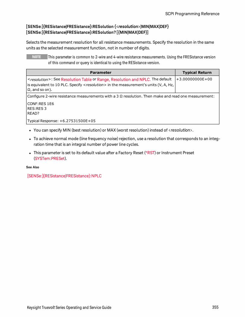
[SENSe:]RESistance|FRESistance:RESolution <resolution>|MIN|MAX|DEF[SENSe:]RESistance|FRESistance:RESolution? [MIN|MAX|DEF]
Selects the measurement resolution for all resistance measurements. Specify the resolution in the sameunits as the selected measurement function, not in number of digits.
This parameter is common to 2-wire and 4-wire resistance measurements. Using the FRESistance versionof this command or query is identical to using the RESistance version.
Parameter Typical Return
<resolution>: See Resolution Table or Range, Resolution and NPLC. The defaultis equivalent to 10 PLC. Specify <resolution> in the measurement's units (V, A, Hz,Ω, and so on).
+3.00000000E+00
Configure 2-wire resistance measurements with a 3 Ω resolution. Then make and read one measurement:
CONF:RES 1E6RES:RES 3READ?
Typical Response: +6.27531500E+05
l You can specify MIN (best resolution) or MAX (worst resolution) instead of <resolution>.
l To achieve normal mode (line frequency noise) rejection, use a resolution that corresponds to an integ-ration time that is an integral number of power line cycles.
l This parameter is set to its default value after a Factory Reset (*RST) or Instrument Preset(SYSTem:PRESet).
See Also
[SENSe:]RESistance|FRESistance:NPLC
Keysight Truevolt Series Operating and Service Guide 355
SCPI Programming Reference
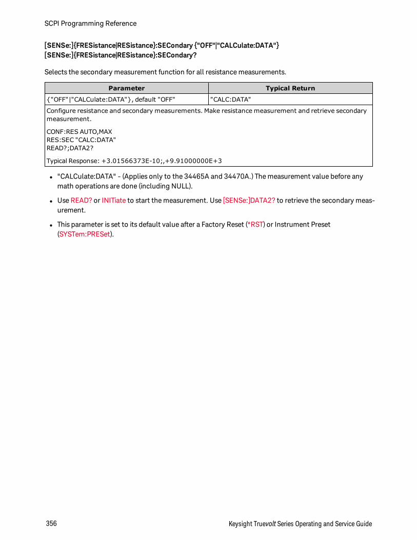
[SENSe:]FRESistance|RESistance:SECondary "OFF"|"CALCulate:DATA"[SENSe:]FRESistance|RESistance:SECondary?
Selects the secondary measurement function for all resistance measurements.
Parameter Typical Return
"OFF"|"CALCulate:DATA", default "OFF" "CALC:DATA"
Configure resistance and secondary measurements. Make resistance measurement and retrieve secondarymeasurement.
CONF:RES AUTO,MAXRES:SEC "CALC:DATA"READ?;DATA2?
Typical Response: +3.01566373E-10;,+9.91000000E+3
l "CALCulate:DATA" - (Applies only to the 34465A and 34470A.) The measurement value before anymath operations are done (including NULL).
l Use READ? or INITiate to start the measurement. Use [SENSe:]DATA2? to retrieve the secondary meas-urement.
l This parameter is set to its default value after a Factory Reset (*RST) or Instrument Preset(SYSTem:PRESet).
SCPI Programming Reference
356 Keysight Truevolt Series Operating and Service Guide
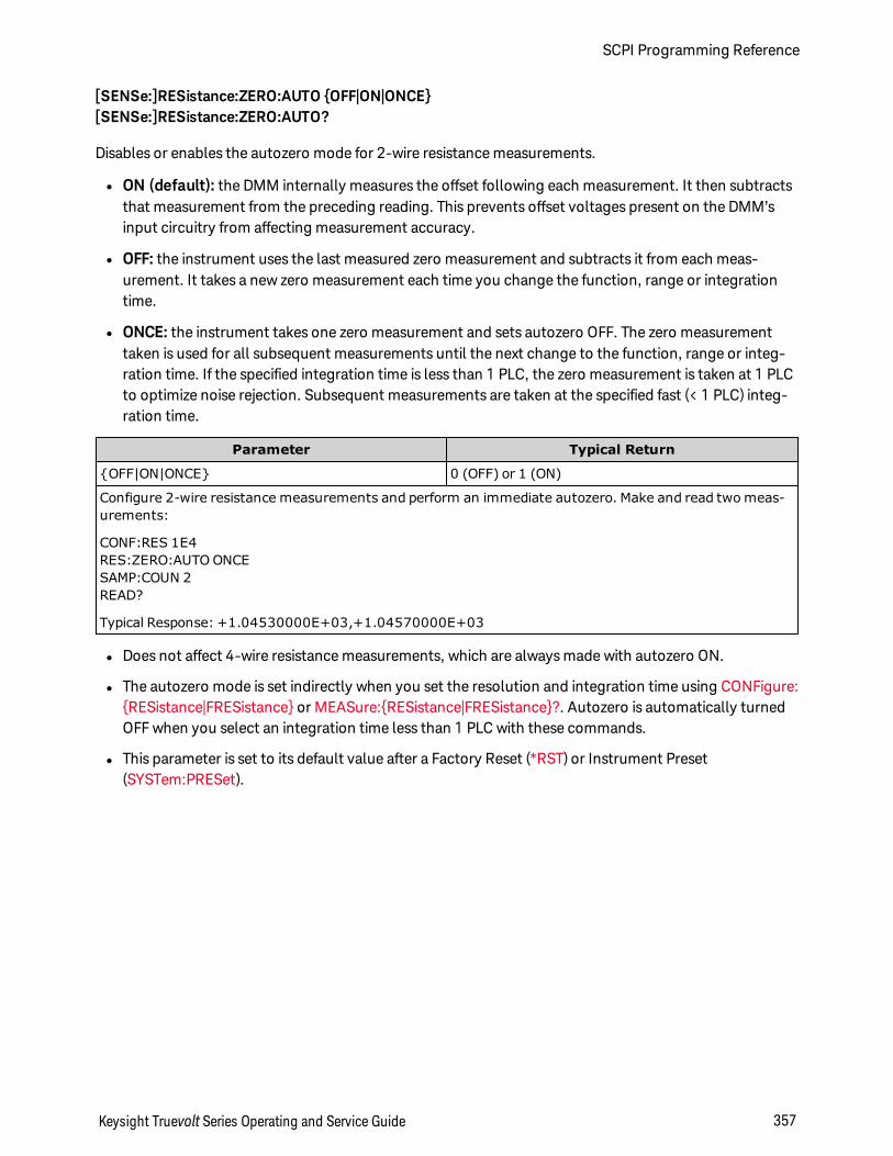
[SENSe:]RESistance:ZERO:AUTO OFF|ON|ONCE[SENSe:]RESistance:ZERO:AUTO?
Disables or enables the autozero mode for 2-wire resistance measurements.
l ON (default): the DMM internally measures the offset following each measurement. It then subtractsthat measurement from the preceding reading. This prevents offset voltages present on the DMM’sinput circuitry from affecting measurement accuracy.
l OFF: the instrument uses the last measured zero measurement and subtracts it from each meas-urement. It takes a new zero measurement each time you change the function, range or integrationtime.
l ONCE: the instrument takes one zero measurement and sets autozero OFF. The zero measurementtaken is used for all subsequent measurements until the next change to the function, range or integ-ration time. If the specified integration time is less than 1 PLC, the zero measurement is taken at 1 PLCto optimize noise rejection. Subsequent measurements are taken at the specified fast (< 1 PLC) integ-ration time.
Parameter Typical Return
OFF|ON|ONCE 0 (OFF) or 1 (ON)
Configure 2-wire resistance measurements and perform an immediate autozero. Make and read two meas-urements:
CONF:RES 1E4RES:ZERO:AUTO ONCESAMP:COUN 2READ?
Typical Response: +1.04530000E+03,+1.04570000E+03
l Does not affect 4-wire resistance measurements, which are always made with autozero ON.
l The autozero mode is set indirectly when you set the resolution and integration time using CONFigure:RESistance|FRESistance or MEASure:RESistance|FRESistance?. Autozero is automatically turnedOFF when you select an integration time less than 1 PLC with these commands.
l This parameter is set to its default value after a Factory Reset (*RST) or Instrument Preset(SYSTem:PRESet).
Keysight Truevolt Series Operating and Service Guide 357
SCPI Programming Reference

[SENSe:]TEMPerature Subsystem
This subsystem configures temperature measurements.
Command Summary
[SENSe:]TEMPerature:APERture
[SENSe:]TEMPerature:APERture:ENABled
[SENSe:]TEMPerature:NPLC
[SENSe:]TEMPerature:NULL[:STATe]
[SENSe:]TEMPerature:NULL:VALue
[SENSe:]TEMPerature:NULL:VALue:AUTO
[SENSe:]TEMPerature:SECondary
[SENSe:]TEMPerature:TRANsducer:FRTD|RTD:OCOMpensated
[SENSe:]TEMPerature:TRANsducer:FRTD|RTD:POWer:LIMit[:STATe]
[SENSe:]TEMPerature:TRANsducer:FRTD|RTD:RESistance[:REFerence]
[SENSe:]TEMPerature:TRANsducer:FTHermistor|THERmistor:POWer:LIMit[:STATe]
[SENSe:]TEMPerature:TRANsducer:FTHermistor|THERmistor:TYPE
[SENSe:]TEMPerature:TRANsducer:TCouple:CHECk
[SENSe:]TEMPerature:TRANsducer:TCouple:RJUNction
[SENSe:]TEMPerature:TRANsducer:TCouple:RJUNction:OFFSet:ADJust
[SENSe:]TEMPerature:TRANsducer:TCouple:RJUNction:TYPE
[SENSe:]TEMPerature:TRANsducer:TCouple:TYPE
[SENSe:]TEMPerature:TRANsducer:TYPE
[SENSe:]TEMPerature:ZERO:AUTO
SCPI Programming Reference
358 Keysight Truevolt Series Operating and Service Guide
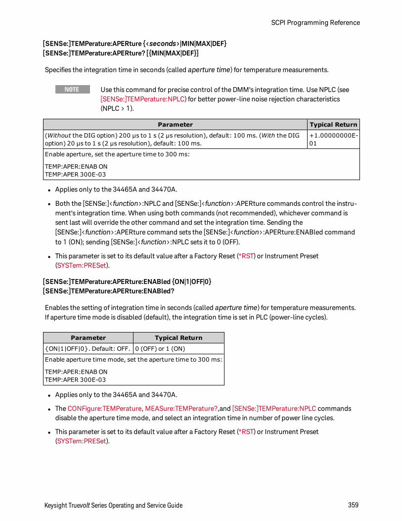
[SENSe:]TEMPerature:APERture <seconds>|MIN|MAX|DEF[SENSe:]TEMPerature:APERture? [MIN|MAX|DEF]
Specifies the integration time in seconds (called aperture time) for temperature measurements.
Use this command for precise control of the DMM's integration time. Use NPLC (see[SENSe:]TEMPerature:NPLC) for better power-line noise rejection characteristics(NPLC > 1).
Parameter Typical Return
(Without the DIG option) 200 µs to 1 s (2 µs resolution), default: 100 ms. (With the DIGoption) 20 µs to 1 s (2 µs resolution), default: 100 ms.
+1.00000000E-01
Enable aperture, set the aperture time to 300 ms:
TEMP:APER:ENAB ONTEMP:APER 300E-03
l Applies only to the 34465A and 34470A.
l Both the [SENSe:]<function>:NPLC and [SENSe:]<function>:APERture commands control the instru-ment's integration time. When using both commands (not recommended), whichever command issent last will override the other command and set the integration time. Sending the[SENSe:]<function>:APERture command sets the [SENSe:]<function>:APERture:ENABled commandto 1 (ON); sending [SENSe:]<function>:NPLC sets it to 0 (OFF).
l This parameter is set to its default value after a Factory Reset (*RST) or Instrument Preset(SYSTem:PRESet).
[SENSe:]TEMPerature:APERture:ENABled ON|1|OFF|0[SENSe:]TEMPerature:APERture:ENABled?
Enables the setting of integration time in seconds (called aperture time) for temperature measurements.If aperture time mode is disabled (default), the integration time is set in PLC (power-line cycles).
Parameter Typical Return
ON|1|OFF|0. Default: OFF. 0 (OFF) or 1 (ON)
Enable aperture time mode, set the aperture time to 300 ms:
TEMP:APER:ENAB ONTEMP:APER 300E-03
l Applies only to the 34465A and 34470A.
l The CONFigure:TEMPerature, MEASure:TEMPerature?,and [SENSe:]TEMPerature:NPLC commandsdisable the aperture time mode, and select an integration time in number of power line cycles.
l This parameter is set to its default value after a Factory Reset (*RST) or Instrument Preset(SYSTem:PRESet).
Keysight Truevolt Series Operating and Service Guide 359
SCPI Programming Reference
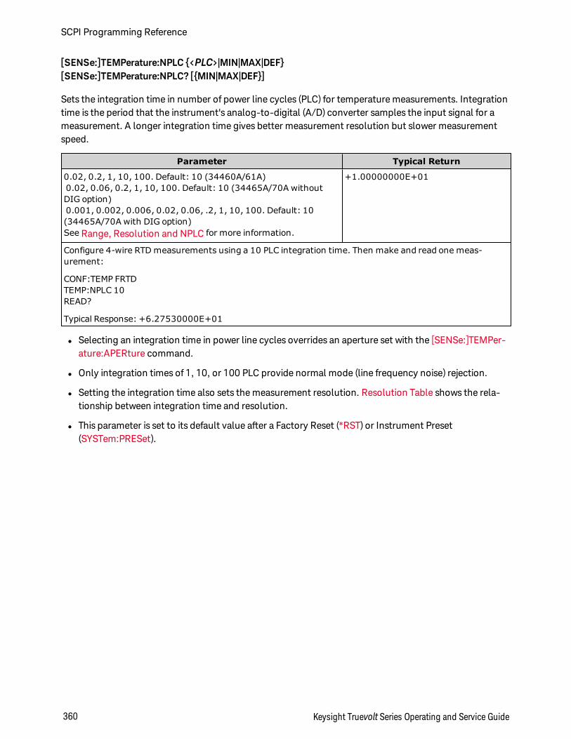
[SENSe:]TEMPerature:NPLC <PLC>|MIN|MAX|DEF[SENSe:]TEMPerature:NPLC? [MIN|MAX|DEF]
Sets the integration time in number of power line cycles (PLC) for temperature measurements. Integrationtime is the period that the instrument's analog-to-digital (A/D) converter samples the input signal for ameasurement. A longer integration time gives better measurement resolution but slower measurementspeed.
Parameter Typical Return
0.02, 0.2, 1, 10, 100. Default: 10 (34460A/61A)0.02, 0.06, 0.2, 1, 10, 100. Default: 10 (34465A/70A withoutDIG option)0.001, 0.002, 0.006, 0.02, 0.06, .2, 1, 10, 100. Default: 10(34465A/70A with DIG option)See Range, Resolution and NPLC for more information.
+1.00000000E+01
Configure 4-wire RTD measurements using a 10 PLC integration time. Then make and read one meas-urement:
CONF:TEMP FRTDTEMP:NPLC 10READ?
Typical Response: +6.27530000E+01
l Selecting an integration time in power line cycles overrides an aperture set with the [SENSe:]TEMPer-ature:APERture command.
l Only integration times of 1, 10, or 100 PLC provide normal mode (line frequency noise) rejection.
l Setting the integration time also sets the measurement resolution. Resolution Table shows the rela-tionship between integration time and resolution.
l This parameter is set to its default value after a Factory Reset (*RST) or Instrument Preset(SYSTem:PRESet).
SCPI Programming Reference
360 Keysight Truevolt Series Operating and Service Guide
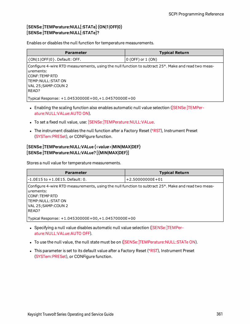
[SENSe:]TEMPerature:NULL[:STATe] ON|1|OFF|0[SENSe:]TEMPerature:NULL[:STATe]?
Enables or disables the null function for temperature measurements.
Parameter Typical Return
ON|1|OFF|0. Default: OFF. 0 (OFF) or 1 (ON)
Configure 4-wire RTD measurements, using the null function to subtract 25°. Make and read two meas-urements:CONF:TEMP RTDTEMP:NULL:STAT ONVAL 25;SAMP:COUN 2READ?
Typical Response: +1.04530000E+00,+1.04570000E+00
l Enabling the scaling function also enables automatic null value selection ([SENSe:]TEMPer-ature:NULL:VALue:AUTO ON).
l To set a fixed null value, use: [SENSe:]TEMPerature:NULL:VALue.
l The instrument disables the null function after a Factory Reset (*RST), Instrument Preset(SYSTem:PRESet), or CONFigure function.
[SENSe:]TEMPerature:NULL:VALue <value>|MIN|MAX|DEF[SENSe:]TEMPerature:NULL:VALue? [MIN|MAX|DEF]
Stores a null value for temperature measurements.
Parameter Typical Return
-1.0E15 to +1.0E15. Default: 0. +2.50000000E+01
Configure 4-wire RTD measurements, using the null function to subtract 25°. Make and read two meas-urements:CONF:TEMP RTDTEMP:NULL:STAT ONVAL 25;SAMP:COUN 2READ?
Typical Response: +1.04530000E+00,+1.04570000E+00
l Specifying a null value disables automatic null value selection ([SENSe:]TEMPer-ature:NULL:VALue:AUTO OFF).
l To use the null value, the null state must be on ([SENSe:]TEMPerature:NULL:STATe ON).
l This parameter is set to its default value after a Factory Reset (*RST), Instrument Preset(SYSTem:PRESet), or CONFigure function.
Keysight Truevolt Series Operating and Service Guide 361
SCPI Programming Reference
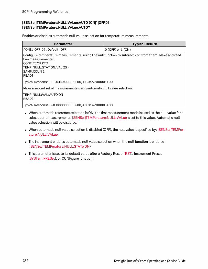
[SENSe:]TEMPerature:NULL:VALue:AUTO ON|1|OFF|0[SENSe:]TEMPerature:NULL:VALue:AUTO?
Enables or disables automatic null value selection for temperature measurements.
Parameter Typical Return
ON|1|OFF|0. Default: OFF. 0 (OFF) or 1 (ON)
Configure temperature measurements, using the null function to subtract 25° from them. Make and readtwo measurements:CONF:TEMP RTDTEMP:NULL:STAT ON;VAL 25>SAMP:COUN 2READ?
Typical Response: +1.04530000E+00,+1.04570000E+00
Make a second set of measurements using automatic null value selection:
TEMP:NULL:VAL:AUTO ONREAD?
Typical Response: +0.00000000E+00,+0.01420000E+00
l When automatic reference selection is ON, the first measurement made is used as the null value for allsubsequent measurements. [SENSe:]TEMPerature:NULL:VALue is set to this value. Automatic nullvalue selection will be disabled.
l When automatic null value selection is disabled (OFF), the null value is specified by: [SENSe:]TEMPer-ature:NULL:VALue.
l The instrument enables automatic null value selection when the null function is enabled([SENSe:]TEMPerature:NULL:STATe ON).
l This parameter is set to its default value after a Factory Reset (*RST), Instrument Preset(SYSTem:PRESet), or CONFigure function.
SCPI Programming Reference
362 Keysight Truevolt Series Operating and Service Guide
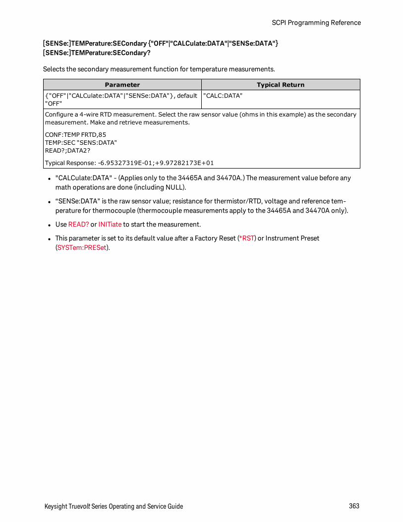
[SENSe:]TEMPerature:SECondary "OFF"|"CALCulate:DATA"|"SENSe:DATA"[SENSe:]TEMPerature:SECondary?
Selects the secondary measurement function for temperature measurements.
Parameter Typical Return
"OFF"|"CALCulate:DATA"|"SENSe:DATA", default"OFF"
"CALC:DATA"
Configure a 4-wire RTD measurement. Select the raw sensor value (ohms in this example) as the secondarymeasurement. Make and retrieve measurements.
CONF:TEMP FRTD,85TEMP:SEC "SENS:DATA"READ?;DATA2?
Typical Response: -6.95327319E-01;+9.97282173E+01
l "CALCulate:DATA" - (Applies only to the 34465A and 34470A.) The measurement value before anymath operations are done (including NULL).
l “SENSe:DATA” is the raw sensor value; resistance for thermistor/RTD, voltage and reference tem-perature for thermocouple (thermocouple measurements apply to the 34465A and 34470A only).
l Use READ? or INITiate to start the measurement.
l This parameter is set to its default value after a Factory Reset (*RST) or Instrument Preset(SYSTem:PRESet).
Keysight Truevolt Series Operating and Service Guide 363
SCPI Programming Reference
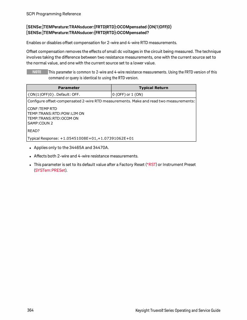
[SENSe:]TEMPerature:TRANsducer:FRTD|RTD:OCOMpensated ON|1|OFF|0[SENSe:]TEMPerature:TRANsducer:FRTD|RTD:OCOMpensated?
Enables or disables offset compensation for 2-wire and 4-wire RTD measurements.
Offset compensation removes the effects of small dc voltages in the circuit being measured. The techniqueinvolves taking the difference between two resistance measurements, one with the current source set tothe normal value, and one with the current source set to a lower value.
This parameter is common to 2-wire and 4-wire resistance measurements. Using the FRTD version of thiscommand or query is identical to using the RTD version.
Parameter Typical Return
ON|1|OFF|0. Default: OFF. 0 (OFF) or 1 (ON)
Configure offset-compensated 2-wire RTD measurements. Make and read two measurements:
CONF:TEMP RTDTEMP:TRANS:RTD:POW:LIM ONTEMP:TRANS:RTD:OCOM ONSAMP:COUN 2
READ?
Typical Response: +1.05451008E+01,+1.07391062E+01
l Applies only to the 34465A and 34470A.
l Affects both 2-wire and 4-wire resistance measurements.
l This parameter is set to its default value after a Factory Reset (*RST) or Instrument Preset(SYSTem:PRESet).
SCPI Programming Reference
364 Keysight Truevolt Series Operating and Service Guide
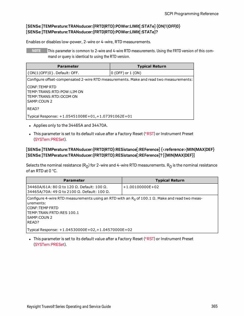
[SENSe:]TEMPerature:TRANsducer:FRTD|RTD:POWer:LIMit[:STATe] ON|1|OFF|0[SENSe:]TEMPerature:TRANsducer:FRTD|RTD:POWer:LIMit[:STATe]?
Enables or disables low-power, 2-wire or 4-wire, RTD measurements.
This parameter is common to 2-wire and 4-wire RTD measurements. Using the FRTD version of this com-mand or query is identical to using the RTD version.
Parameter Typical Return
ON|1|OFF|0. Default: OFF. 0 (OFF) or 1 (ON)
Configure offset-compensated 2-wire RTD measurements. Make and read two measurements:
CONF:TEMP RTDTEMP:TRANS:RTD:POW:LIM ONTEMP:TRANS:RTD:OCOM ONSAMP:COUN 2
READ?
Typical Response: +1.05451008E+01,+1.07391062E+01
l Applies only to the 34465A and 34470A.
l This parameter is set to its default value after a Factory Reset (*RST) or Instrument Preset(SYSTem:PRESet).
[SENSe:]TEMPerature:TRANsducer:FRTD|RTD:RESistance[:REFerence] <reference>|MIN|MAX|DEF[SENSe:]TEMPerature:TRANsducer:FRTD|RTD:RESistance[:REFerence]? [MIN|MAX|DEF]
Selects the nominal resistance (R0) for 2-wire and 4-wire RTD measurements. R0 is the nominal resistanceof an RTD at 0 °C.
Parameter Typical Return
34460A/61A: 80 Ω to 120 Ω. Default: 100 Ω.34465A/70A: 49 Ω to 2100 Ω. Default: 100 Ω.
+1.00100000E+02
Configure 4-wire RTD measurements using an RTD with an R0 of 100.1 Ω. Make and read two meas-urements:CONF:TEMP FRTDTEMP:TRAN:FRTD:RES 100.1SAMP:COUN 2READ?
Typical Response: +1.04530000E+02,+1.04570000E+02
l This parameter is set to its default value after a Factory Reset (*RST) or Instrument Preset(SYSTem:PRESet).
Keysight Truevolt Series Operating and Service Guide 365
SCPI Programming Reference
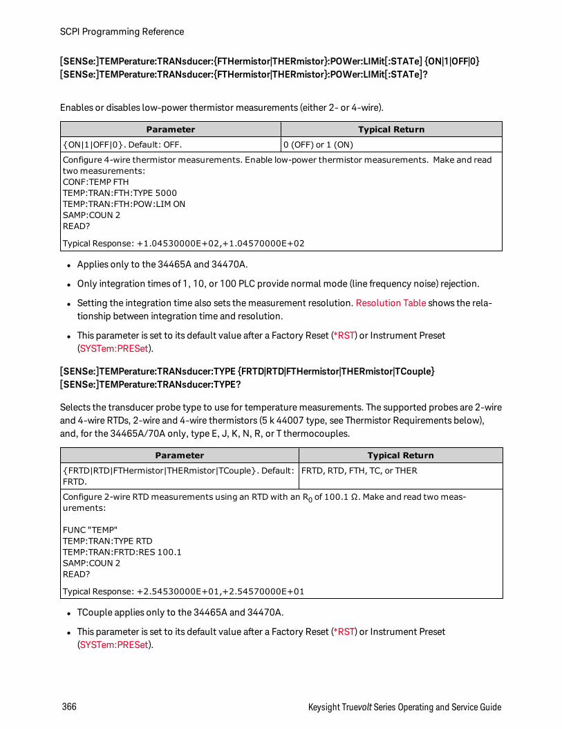
[SENSe:]TEMPerature:TRANsducer:FTHermistor|THERmistor:POWer:LIMit[:STATe] ON|1|OFF|0[SENSe:]TEMPerature:TRANsducer:FTHermistor|THERmistor:POWer:LIMit[:STATe]?
Enables or disables low-power thermistor measurements (either 2- or 4-wire).
Parameter Typical Return
ON|1|OFF|0. Default: OFF. 0 (OFF) or 1 (ON)
Configure 4-wire thermistor measurements. Enable low-power thermistor measurements. Make and readtwo measurements:CONF:TEMP FTHTEMP:TRAN:FTH:TYPE 5000TEMP:TRAN:FTH:POW:LIM ONSAMP:COUN 2READ?
Typical Response: +1.04530000E+02,+1.04570000E+02
l Applies only to the 34465A and 34470A.
l Only integration times of 1, 10, or 100 PLC provide normal mode (line frequency noise) rejection.
l Setting the integration time also sets the measurement resolution. Resolution Table shows the rela-tionship between integration time and resolution.
l This parameter is set to its default value after a Factory Reset (*RST) or Instrument Preset(SYSTem:PRESet).
[SENSe:]TEMPerature:TRANsducer:TYPE FRTD|RTD|FTHermistor|THERmistor|TCouple[SENSe:]TEMPerature:TRANsducer:TYPE?
Selects the transducer probe type to use for temperature measurements. The supported probes are 2-wireand 4-wire RTDs, 2-wire and 4-wire thermistors (5 k 44007 type, see Thermistor Requirements below),and, for the 34465A/70A only, type E, J, K, N, R, or T thermocouples.
Parameter Typical Return
FRTD|RTD|FTHermistor|THERmistor|TCouple. Default:FRTD.
FRTD, RTD, FTH, TC, or THER
Configure 2-wire RTD measurements using an RTD with an R0 of 100.1 Ω. Make and read two meas-urements:
FUNC "TEMP"TEMP:TRAN:TYPE RTDTEMP:TRAN:FRTD:RES 100.1SAMP:COUN 2READ?
Typical Response: +2.54530000E+01,+2.54570000E+01
l TCouple applies only to the 34465A and 34470A.
l This parameter is set to its default value after a Factory Reset (*RST) or Instrument Preset(SYSTem:PRESet).
SCPI Programming Reference
366 Keysight Truevolt Series Operating and Service Guide
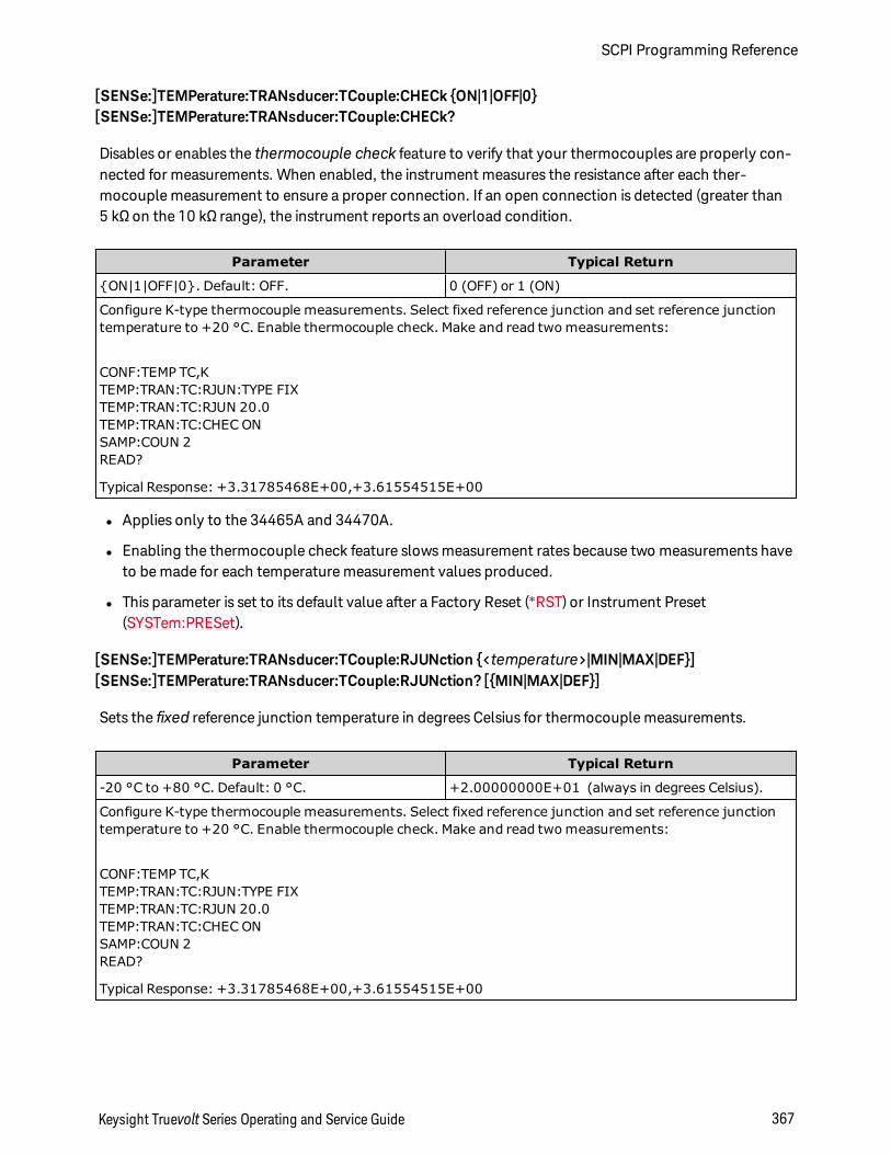
[SENSe:]TEMPerature:TRANsducer:TCouple:CHECk ON|1|OFF|0[SENSe:]TEMPerature:TRANsducer:TCouple:CHECk?
Disables or enables the thermocouple check feature to verify that your thermocouples are properly con-nected for measurements. When enabled, the instrument measures the resistance after each ther-mocouple measurement to ensure a proper connection. If an open connection is detected (greater than5 kΩ on the 10 kΩ range), the instrument reports an overload condition.
Parameter Typical Return
ON|1|OFF|0. Default: OFF. 0 (OFF) or 1 (ON)
Configure K-type thermocouple measurements. Select fixed reference junction and set reference junctiontemperature to +20 °C. Enable thermocouple check. Make and read two measurements:
CONF:TEMP TC,KTEMP:TRAN:TC:RJUN:TYPE FIXTEMP:TRAN:TC:RJUN 20.0TEMP:TRAN:TC:CHEC ONSAMP:COUN 2READ?
Typical Response: +3.31785468E+00,+3.61554515E+00
l Applies only to the 34465A and 34470A.
l Enabling the thermocouple check feature slows measurement rates because two measurements haveto be made for each temperature measurement values produced.
l This parameter is set to its default value after a Factory Reset (*RST) or Instrument Preset(SYSTem:PRESet).
[SENSe:]TEMPerature:TRANsducer:TCouple:RJUNction <temperature>|MIN|MAX|DEF][SENSe:]TEMPerature:TRANsducer:TCouple:RJUNction? [MIN|MAX|DEF]
Sets the fixed reference junction temperature in degrees Celsius for thermocouple measurements.
Parameter Typical Return
-20 °C to +80 °C. Default: 0 °C. +2.00000000E+01 (always in degrees Celsius).
Configure K-type thermocouple measurements. Select fixed reference junction and set reference junctiontemperature to +20 °C. Enable thermocouple check. Make and read two measurements:
CONF:TEMP TC,KTEMP:TRAN:TC:RJUN:TYPE FIXTEMP:TRAN:TC:RJUN 20.0TEMP:TRAN:TC:CHEC ONSAMP:COUN 2READ?
Typical Response: +3.31785468E+00,+3.61554515E+00
Keysight Truevolt Series Operating and Service Guide 367
SCPI Programming Reference
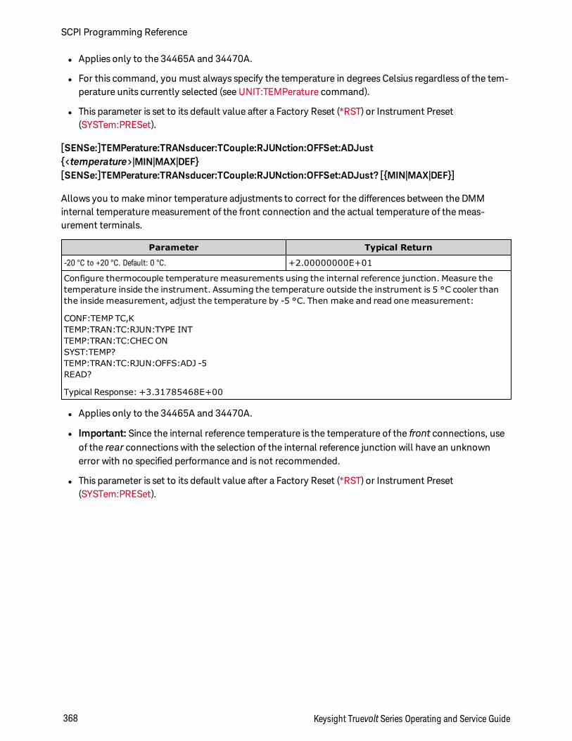
l Applies only to the 34465A and 34470A.
l For this command, you must always specify the temperature in degrees Celsius regardless of the tem-perature units currently selected (see UNIT:TEMPerature command).
l This parameter is set to its default value after a Factory Reset (*RST) or Instrument Preset(SYSTem:PRESet).
[SENSe:]TEMPerature:TRANsducer:TCouple:RJUNction:OFFSet:ADJust<temperature>|MIN|MAX|DEF[SENSe:]TEMPerature:TRANsducer:TCouple:RJUNction:OFFSet:ADJust? [MIN|MAX|DEF]
Allows you to make minor temperature adjustments to correct for the differences between the DMMinternal temperature measurement of the front connection and the actual temperature of the meas-urement terminals.
Parameter Typical Return
-20 °C to +20 °C. Default: 0 °C. +2.00000000E+01
Configure thermocouple temperature measurements using the internal reference junction. Measure thetemperature inside the instrument. Assuming the temperature outside the instrument is 5 °C cooler thanthe inside measurement, adjust the temperature by -5 °C. Then make and read one measurement:
CONF:TEMP TC,KTEMP:TRAN:TC:RJUN:TYPE INTTEMP:TRAN:TC:CHEC ONSYST:TEMP?TEMP:TRAN:TC:RJUN:OFFS:ADJ -5READ?
Typical Response: +3.31785468E+00
l Applies only to the 34465A and 34470A.
l Important: Since the internal reference temperature is the temperature of the front connections, useof the rear connections with the selection of the internal reference junction will have an unknownerror with no specified performance and is not recommended.
l This parameter is set to its default value after a Factory Reset (*RST) or Instrument Preset(SYSTem:PRESet).
SCPI Programming Reference
368 Keysight Truevolt Series Operating and Service Guide
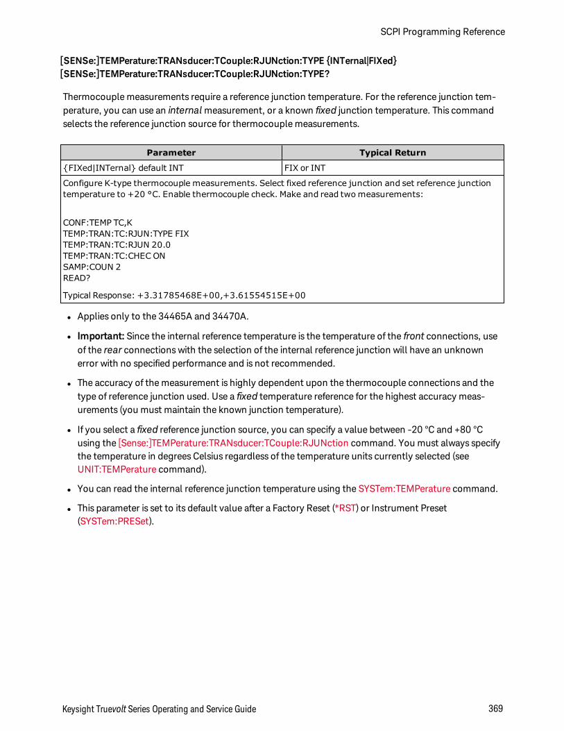
[SENSe:]TEMPerature:TRANsducer:TCouple:RJUNction:TYPE INTernal|FIXed[SENSe:]TEMPerature:TRANsducer:TCouple:RJUNction:TYPE?
Thermocouple measurements require a reference junction temperature. For the reference junction tem-perature, you can use an internal measurement, or a known fixed junction temperature. This commandselects the reference junction source for thermocouple measurements.
Parameter Typical Return
FIXed|INTernal default INT FIX or INT
Configure K-type thermocouple measurements. Select fixed reference junction and set reference junctiontemperature to +20 °C. Enable thermocouple check. Make and read two measurements:
CONF:TEMP TC,KTEMP:TRAN:TC:RJUN:TYPE FIXTEMP:TRAN:TC:RJUN 20.0TEMP:TRAN:TC:CHEC ONSAMP:COUN 2READ?
Typical Response: +3.31785468E+00,+3.61554515E+00
l Applies only to the 34465A and 34470A.
l Important: Since the internal reference temperature is the temperature of the front connections, useof the rear connections with the selection of the internal reference junction will have an unknownerror with no specified performance and is not recommended.
l The accuracy of the measurement is highly dependent upon the thermocouple connections and thetype of reference junction used. Use a fixed temperature reference for the highest accuracy meas-urements (you must maintain the known junction temperature).
l If you select a fixed reference junction source, you can specify a value between -20 °C and +80 °Cusing the [Sense:]TEMPerature:TRANsducer:TCouple:RJUNction command. You must always specifythe temperature in degrees Celsius regardless of the temperature units currently selected (seeUNIT:TEMPerature command).
l You can read the internal reference junction temperature using the SYSTem:TEMPerature command.
l This parameter is set to its default value after a Factory Reset (*RST) or Instrument Preset(SYSTem:PRESet).
Keysight Truevolt Series Operating and Service Guide 369
SCPI Programming Reference
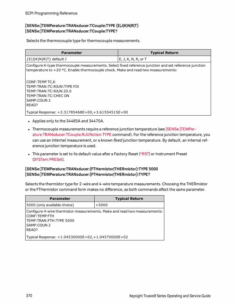
[SENSe:]TEMPerature:TRANsducer:TCouple:TYPE E|J|K|N|R|T[SENSe:]TEMPerature:TRANsducer:TCouple:TYPE?
Selects the thermocouple type for thermocouple measurements.
Parameter Typical Return
E|J|K|N|R|T default J E, J, K, N, R, or T
Configure K-type thermocouple measurements. Select fixed reference junction and set reference junctiontemperature to +20 °C. Enable thermocouple check. Make and read two measurements:
CONF:TEMP TC,KTEMP:TRAN:TC:RJUN:TYPE FIXTEMP:TRAN:TC:RJUN 20.0TEMP:TRAN:TC:CHEC ONSAMP:COUN 2READ?
Typical Response: +3.31785468E+00,+3.61554515E+00
l Applies only to the 34465A and 34470A.
l Thermocouple measurements require a reference junction temperature (see [SENSe:]TEMPer-ature:TRANsducer:TCouple:RJUNction:TYPE command). For the reference junction temperature, youcan use an internal measurement, or a known fixed junction temperature. By default, an internal ref-erence junction temperature is used.
l This parameter is set to its default value after a Factory Reset (*RST) or Instrument Preset(SYSTem:PRESet).
[SENSe:]TEMPerature:TRANsducer:FTHermistor|THERmistor:TYPE 5000[SENSe:]TEMPerature:TRANsducer:FTHermistor|THERmistor:TYPE?
Selects the thermistor type for 2-wire and 4-wire temperature measurements. Choosing the THERmistoror the FTHermistor command form makes no difference, as both commands affect the same parameter.
Parameter Typical Return
5000 (only available choice) +5000
Configure 4-wire thermistor measurements. Make and read two measurements:CONF:TEMP FTHTEMP:TRAN:FTH:TYPE 5000SAMP:COUN 2READ?
Typical Response: +1.04530000E+02,+1.04570000E+02
SCPI Programming Reference
370 Keysight Truevolt Series Operating and Service Guide
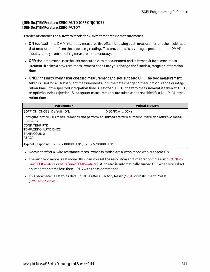
[SENSe:]TEMPerature:ZERO:AUTO OFF|ON|ONCE[SENSe:]TEMPerature:ZERO:AUTO?
Disables or enables the autozero mode for 2-wire temperature measurements.
l ON (default): the DMM internally measures the offset following each measurement. It then subtractsthat measurement from the preceding reading. This prevents offset voltages present on the DMM’sinput circuitry from affecting measurement accuracy.
l OFF: the instrument uses the last measured zero measurement and subtracts it from each meas-urement. It takes a new zero measurement each time you change the function, range or integrationtime.
l ONCE: the instrument takes one zero measurement and sets autozero OFF. The zero measurementtaken is used for all subsequent measurements until the next change to the function, range or integ-ration time. If the specified integration time is less than 1 PLC, the zero measurement is taken at 1 PLCto optimize noise rejection. Subsequent measurements are taken at the specified fast (< 1 PLC) integ-ration time.
Parameter Typical Return
OFF|ON|ONCE. Default: ON. 0 (OFF) or 1 (ON)
Configure 2-wire RTD measurements and perform an immediate zero autozero. Make and read two meas-urements:CONF:TEMP RTDTEMP:ZERO:AUTO ONCESAMP:COUN 2READ?
Typical Response: +2.57530000E+01,+2.57570000E+01
l Does not affect 4-wire resistance measurements, which are always made with autozero ON.
l The autozero mode is set indirectly when you set the resolution and integration time using CONFig-ure:TEMPerature or MEASure:TEMPerature?. Autozero is automatically turned OFF when you selectan integration time less than 1 PLC with these commands.
l This parameter is set to its default value after a Factory Reset (*RST) or Instrument Preset(SYSTem:PRESet).
Keysight Truevolt Series Operating and Service Guide 371
SCPI Programming Reference
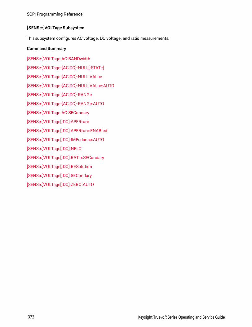
[SENSe:]VOLTage Subsystem
This subsystem configures AC voltage, DC voltage, and ratio measurements.
Command Summary
[SENSe:]VOLTage:AC:BANDwidth
[SENSe:]VOLTage:AC|DC:NULL[:STATe]
[SENSe:]VOLTage:AC|DC:NULL:VALue
[SENSe:]VOLTage:AC|DC:NULL:VALue:AUTO
[SENSe:]VOLTage:AC|DC:RANGe
[SENSe:]VOLTage:AC|DC:RANGe:AUTO
[SENSe:]VOLTage:AC:SECondary
[SENSe:]VOLTage[:DC]:APERture
[SENSe:]VOLTage[:DC]:APERture:ENABled
[SENSe:]VOLTage[:DC]:IMPedance:AUTO
[SENSe:]VOLTage[:DC]:NPLC
[SENSe:]VOLTage[:DC]:RATio:SECondary
[SENSe:]VOLTage[:DC]:RESolution
[SENSe:]VOLTage[:DC]:SECondary
[SENSe:]VOLTage[:DC]:ZERO:AUTO
SCPI Programming Reference
372 Keysight Truevolt Series Operating and Service Guide
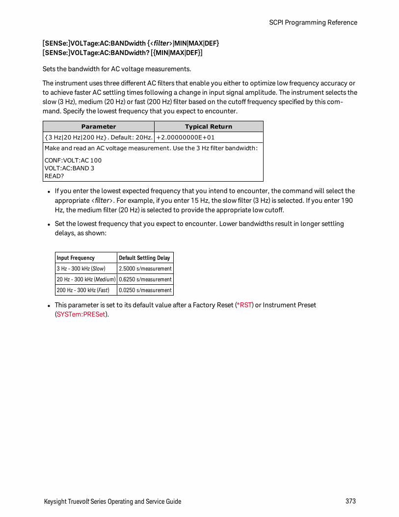
[SENSe:]VOLTage:AC:BANDwidth <filter>|MIN|MAX|DEF[SENSe:]VOLTage:AC:BANDwidth? [MIN|MAX|DEF]
Sets the bandwidth for AC voltage measurements.
The instrument uses three different AC filters that enable you either to optimize low frequency accuracy orto achieve faster AC settling times following a change in input signal amplitude. The instrument selects theslow (3 Hz), medium (20 Hz) or fast (200 Hz) filter based on the cutoff frequency specified by this com-mand. Specify the lowest frequency that you expect to encounter.
Parameter Typical Return
3 Hz|20 Hz|200 Hz. Default: 20Hz. +2.00000000E+01
Make and read an AC voltage measurement. Use the 3 Hz filter bandwidth:
CONF:VOLT:AC 100VOLT:AC:BAND 3READ?
l If you enter the lowest expected frequency that you intend to encounter, the command will select theappropriate <filter>. For example, if you enter 15 Hz, the slow filter (3 Hz) is selected. If you enter 190Hz, the medium filter (20 Hz) is selected to provide the appropriate low cutoff.
l Set the lowest frequency that you expect to encounter. Lower bandwidths result in longer settlingdelays, as shown:
Input Frequency Default Settling Delay
3 Hz - 300 kHz (Slow) 2.5000 s/measurement
20 Hz - 300 kHz (Medium) 0.6250 s/measurement
200 Hz - 300 kHz (Fast) 0.0250 s/measurement
l This parameter is set to its default value after a Factory Reset (*RST) or Instrument Preset(SYSTem:PRESet).
Keysight Truevolt Series Operating and Service Guide 373
SCPI Programming Reference
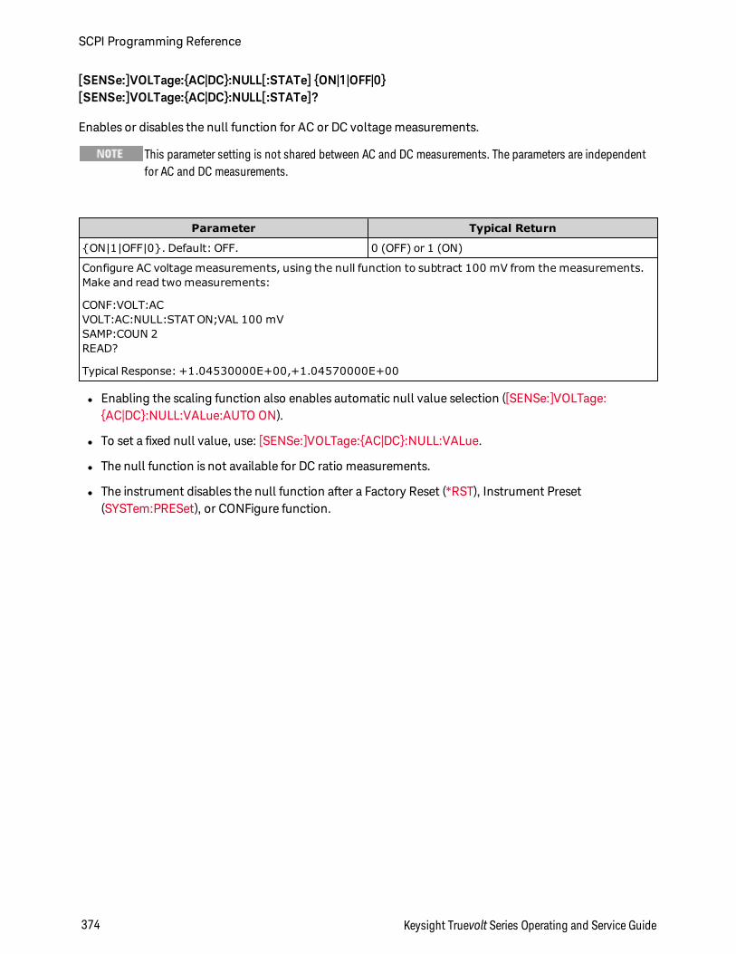
[SENSe:]VOLTage:AC|DC:NULL[:STATe] ON|1|OFF|0[SENSe:]VOLTage:AC|DC:NULL[:STATe]?
Enables or disables the null function for AC or DC voltage measurements.
This parameter setting is not shared between AC and DC measurements. The parameters are independentfor AC and DC measurements.
Parameter Typical Return
ON|1|OFF|0. Default: OFF. 0 (OFF) or 1 (ON)
Configure AC voltage measurements, using the null function to subtract 100 mV from the measurements.Make and read two measurements:
CONF:VOLT:ACVOLT:AC:NULL:STAT ON;VAL 100 mVSAMP:COUN 2READ?
Typical Response: +1.04530000E+00,+1.04570000E+00
l Enabling the scaling function also enables automatic null value selection ([SENSe:]VOLTage:AC|DC:NULL:VALue:AUTO ON).
l To set a fixed null value, use: [SENSe:]VOLTage:AC|DC:NULL:VALue.
l The null function is not available for DC ratio measurements.
l The instrument disables the null function after a Factory Reset (*RST), Instrument Preset(SYSTem:PRESet), or CONFigure function.
SCPI Programming Reference
374 Keysight Truevolt Series Operating and Service Guide
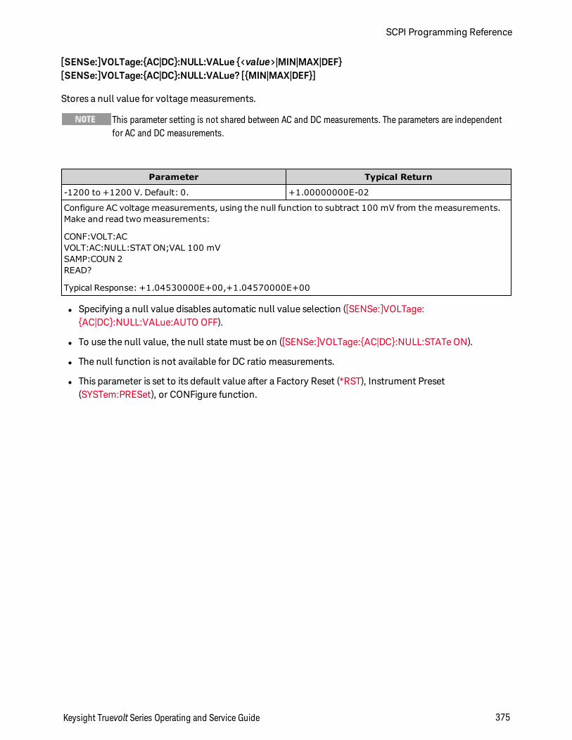
[SENSe:]VOLTage:AC|DC:NULL:VALue <value>|MIN|MAX|DEF[SENSe:]VOLTage:AC|DC:NULL:VALue? [MIN|MAX|DEF]
Stores a null value for voltage measurements.
This parameter setting is not shared between AC and DC measurements. The parameters are independentfor AC and DC measurements.
Parameter Typical Return
-1200 to +1200 V. Default: 0. +1.00000000E-02
Configure AC voltage measurements, using the null function to subtract 100 mV from the measurements.Make and read two measurements:
CONF:VOLT:ACVOLT:AC:NULL:STAT ON;VAL 100 mVSAMP:COUN 2READ?
Typical Response: +1.04530000E+00,+1.04570000E+00
l Specifying a null value disables automatic null value selection ([SENSe:]VOLTage:AC|DC:NULL:VALue:AUTO OFF).
l To use the null value, the null state must be on ([SENSe:]VOLTage:AC|DC:NULL:STATe ON).
l The null function is not available for DC ratio measurements.
l This parameter is set to its default value after a Factory Reset (*RST), Instrument Preset(SYSTem:PRESet), or CONFigure function.
Keysight Truevolt Series Operating and Service Guide 375
SCPI Programming Reference
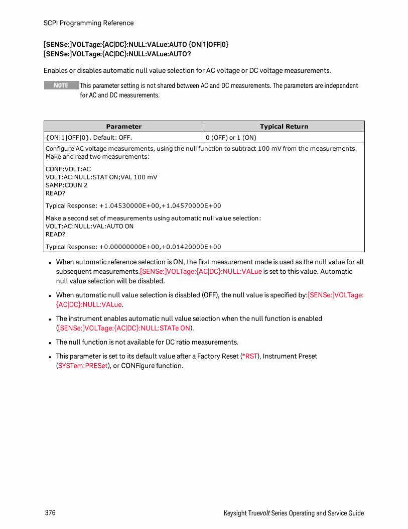
[SENSe:]VOLTage:AC|DC:NULL:VALue:AUTO ON|1|OFF|0[SENSe:]VOLTage:AC|DC:NULL:VALue:AUTO?
Enables or disables automatic null value selection for AC voltage or DC voltage measurements.
This parameter setting is not shared between AC and DC measurements. The parameters are independentfor AC and DC measurements.
Parameter Typical Return
ON|1|OFF|0. Default: OFF. 0 (OFF) or 1 (ON)
Configure AC voltage measurements, using the null function to subtract 100 mV from the measurements.Make and read two measurements:
CONF:VOLT:ACVOLT:AC:NULL:STAT ON;VAL 100 mVSAMP:COUN 2READ?
Typical Response: +1.04530000E+00,+1.04570000E+00
Make a second set of measurements using automatic null value selection:VOLT:AC:NULL:VAL:AUTO ONREAD?
Typical Response: +0.00000000E+00,+0.01420000E+00
l When automatic reference selection is ON, the first measurement made is used as the null value for allsubsequent measurements.[SENSe:]VOLTage:AC|DC:NULL:VALue is set to this value. Automaticnull value selection will be disabled.
l When automatic null value selection is disabled (OFF), the null value is specified by:[SENSe:]VOLTage:AC|DC:NULL:VALue.
l The instrument enables automatic null value selection when the null function is enabled([SENSe:]VOLTage:AC|DC:NULL:STATe ON).
l The null function is not available for DC ratio measurements.
l This parameter is set to its default value after a Factory Reset (*RST), Instrument Preset(SYSTem:PRESet), or CONFigure function.
SCPI Programming Reference
376 Keysight Truevolt Series Operating and Service Guide
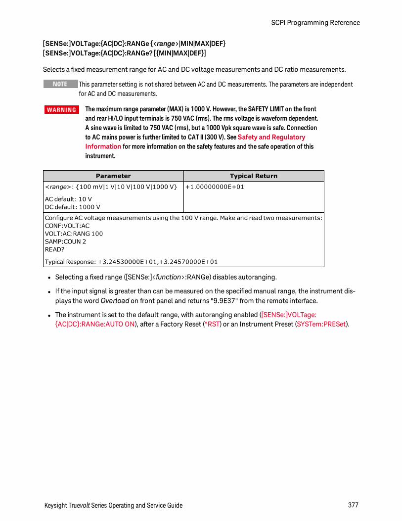
[SENSe:]VOLTage:AC|DC:RANGe <range>|MIN|MAX|DEF[SENSe:]VOLTage:AC|DC:RANGe? [MIN|MAX|DEF]
Selects a fixed measurement range for AC and DC voltage measurements and DC ratio measurements.
This parameter setting is not shared between AC and DC measurements. The parameters are independentfor AC and DC measurements.
The maximum range parameter (MAX) is 1000 V. However, the SAFETY LIMIT on the frontand rear HI/LO input terminals is 750 VAC (rms). The rms voltage is waveform dependent.A sine wave is limited to 750 VAC (rms), but a 1000 Vpk square wave is safe. Connectionto AC mains power is further limited to CAT II (300 V). SeeSafety and RegulatoryInformation for more information on the safety features and the safe operation of thisinstrument.
Parameter Typical Return
<range>: 100 mV|1 V|10 V|100 V|1000 V
AC default: 10 VDC default: 1000 V
+1.00000000E+01
Configure AC voltage measurements using the 100 V range. Make and read two measurements:CONF:VOLT:ACVOLT:AC:RANG 100SAMP:COUN 2READ?
Typical Response: +3.24530000E+01,+3.24570000E+01
l Selecting a fixed range ([SENSe:]<function>:RANGe) disables autoranging.
l If the input signal is greater than can be measured on the specified manual range, the instrument dis-plays the word Overload on front panel and returns "9.9E37" from the remote interface.
l The instrument is set to the default range, with autoranging enabled ([SENSe:]VOLTage:AC|DC:RANGe:AUTO ON), after a Factory Reset (*RST) or an Instrument Preset (SYSTem:PRESet).
Keysight Truevolt Series Operating and Service Guide 377
SCPI Programming Reference
[SENSe:]VOLTage:AC|DC:RANGe:AUTO OFF|ON|ONCE[SENSe:]VOLTage:AC|DC:RANGe:AUTO?
Disables or enables autoranging for AC and DC voltage measurements and for DC ratio measurements.Autoranging is convenient because it automatically selects the range for each measurement based on theinput signal.
Specifying ONCE performs an immediate autorange and then turns autoranging off.
This parameter setting is not shared between AC and DC measurements. The parameters are independentfor AC and DC measurements.
The maximum range parameter (MAX) is 1000 V. However, the SAFETY LIMIT on the frontand rear HI/LO input terminals is 750 VAC (rms). The rms voltage is waveform dependent.A sine wave is limited to 750 VAC (rms), but a 1000 Vpk square wave is safe. Connectionto AC mains power is further limited to CAT II (300 V). SeeSafety and RegulatoryInformation for more information on the safety features and the safe operation of thisinstrument.
Parameter Typical Return
ON|1|OFF|0. Default: ON. 0 (OFF) or 1 (ON)
Configure DC voltage measurements and perform an immediate autorange. Make and read two meas-urements:CONF:VOLT:ACVOLT:AC:RANG:AUTO ONCESAMP:COUN 2READ?
Typical Response: +1.04530000E+01,+1.04570000E+01
l Autoranging goes down a range at less than 10% of range and up a range at greater than 120% ofrange.
l With autoranging enabled, the instrument selects the range based on the input signal.
l Selecting a fixed range ([SENSe:]<function>:RANGe) disables autoranging.
l This parameter is set to its default value after a Factory Reset (*RST) or Instrument Preset(SYSTem:PRESet).
SCPI Programming Reference
378 Keysight Truevolt Series Operating and Service Guide
[SENSe:]VOLTage:AC:SECondary "OFF"|"CALCulate:DATA"|"FREQuency"|"VOLTage[:DC]"[SENSe:]VOLTage:AC:SECondary?
Selects the secondary measurement function for AC voltage measurements.
Parameter Typical Return
"OFF"|"CALCulate:DATA"|"FREQuency"|"VOLTage[:DC]", default "OFF"
"CALC:DATA"
Configure AC voltage measurements using the 100 V range. Select frequency as the secondary meas-urement. Make and retrieve measurements.
CONF:VOLT:AC 100VOLT:AC:SEC "FREQ"READ?;DATA2?
Typical Response: +8.54530000E+01;+1.00000000E+03
l "CALCulate:DATA" - (Applies only to the 34465A and 34470A.) The measurement value before anymath operations are done (including NULL).
l "FREQuency" - The frequency measurement of the input signal.
l "VOLTage[:DC]" - The DC voltage measurement of the input signal. Applies only when using the instru-ment from the front panel. Setting is ignored for measurements made from a remote interface. If yourequire both AC and DC voltage measurements from remote, program each function separately, seeCONFigure[:VOLTage]:AC|DC.
l Use READ? or INITiate to start the measurement.
l This parameter is set to its default value after a Factory Reset (*RST) or Instrument Preset(SYSTem:PRESet).
[SENSe:]VOLTage[:DC]:APERture <seconds>|MIN|MAX|DEF[SENSe:]VOLTage[:DC]:APERture? [MIN|MAX|DEF]
Specifies the integration time in seconds (called aperture time) for dc voltage measurements.
Use this command for precise control of the DMM's integration time. Use NPLC (see[SENSe:]VOLTage[:DC]:NPLC) for better power-line noise rejection characteristics(NPLC > 1).
Parameter Typical Return
(Without the DIG option) 200 µs to 1 s (2 µs resolution), default: 100 ms. (With the DIGoption) 20 µs to 1 s (2 µs resolution), default: 100 ms.
+1.00000000E-01
Enable aperture time mode, set the aperture time to 300 ms:
VOLT:APER:ENAB ONVOLT:DC:APER 300E-03
Keysight Truevolt Series Operating and Service Guide 379
SCPI Programming Reference
l Applies only to the 34465A and 34470A.
l Both the [SENSe:]<function>:NPLC and [SENSe:]<function>:APERture commands control the instru-ment's integration time. When using both commands (not recommended), whichever command issent last will override the other command and set the integration time. Sending the[SENSe:]<function>:APERture command sets the [SENSe:]<function>:APERture:ENABled commandto 1 (ON); sending [SENSe:]<function>:NPLC sets it to 0 (OFF).
l This parameter is set to its default value after a Factory Reset (*RST) or Instrument Preset(SYSTem:PRESet).
[SENSe:]VOLTage[:DC]:APERture:ENABled ON|1|OFF|0[SENSe:]VOLTage[:DC]:APERture:ENABled?
Enables the setting of integration time in seconds (called aperture time) for dc voltage measurements. Ifaperture time mode is disabled (default), the integration time is set in PLC (power-line cycles).
Parameter Typical Return
ON|1|OFF|0. Default: OFF. 0 (OFF) or 1 (ON)
Enable aperture time mode, set the aperture time to 300 ms:
VOLT:APER:ENAB ONVOLT:DC:APER 300E-03
l Applies only to the 34465A and 34470A.
l The CONFigure[:VOLTage][:DC], MEASure[:VOLTage][:DC]?, [SENSe:]VOLTage[:DC]:NPLC, and[SENSe:]VOLTage[:DC]:RESolution commands disable the aperture time mode, and select an integ-ration time in number of power line cycles.
l This parameter is set to its default value after a Factory Reset (*RST) or Instrument Preset(SYSTem:PRESet).
SCPI Programming Reference
380 Keysight Truevolt Series Operating and Service Guide
[SENSe:]VOLTage[:DC]:IMPedance:AUTO ON|1|OFF|0[SENSe:]VOLTage[:DC]:IMPedance:AUTO?
Disables or enables automatic input impedance mode for DC voltage and ratio measurements.
Parameter Typical Return
ON|1|OFF|0. Default: OFF. 0 (OFF) or 1 (ON)
Make all DC voltage measurements with a 10 MΩ input impedance:
VOLT:IMP:AUTO OFF
l OFF: the input impedance for DC voltage measurements is fixed at 10 MΩ for all ranges to minimizenoise pickup.
l ON: the input impedance for DC voltage measurements varies by range. It is set to "HI-Z" (>10 GΩ) forthe 100 mV, 1 V, and 10 V ranges to reduce the effects of measurement loading errors on these lowerranges. The 100 V and 1000 V ranges remain at a 10 MΩ input impedance.
l The CONFigure and MEASure? commands automatically select "AUTO OFF".
l This parameter is set to its default value after a Factory Reset (*RST) or Instrument Preset(SYSTem:PRESet).
Keysight Truevolt Series Operating and Service Guide 381
SCPI Programming Reference
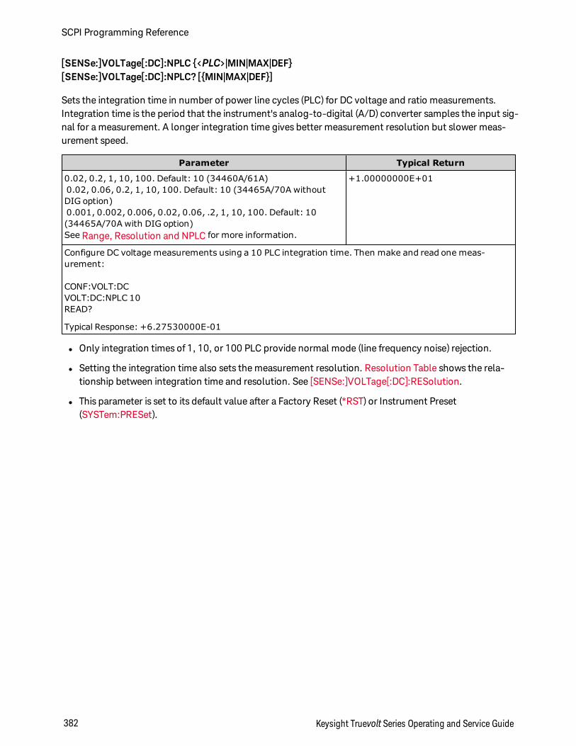
[SENSe:]VOLTage[:DC]:NPLC <PLC>|MIN|MAX|DEF[SENSe:]VOLTage[:DC]:NPLC? [MIN|MAX|DEF]
Sets the integration time in number of power line cycles (PLC) for DC voltage and ratio measurements.Integration time is the period that the instrument's analog-to-digital (A/D) converter samples the input sig-nal for a measurement. A longer integration time gives better measurement resolution but slower meas-urement speed.
Parameter Typical Return
0.02, 0.2, 1, 10, 100. Default: 10 (34460A/61A)0.02, 0.06, 0.2, 1, 10, 100. Default: 10 (34465A/70A withoutDIG option)0.001, 0.002, 0.006, 0.02, 0.06, .2, 1, 10, 100. Default: 10(34465A/70A with DIG option)See Range, Resolution and NPLC for more information.
+1.00000000E+01
Configure DC voltage measurements using a 10 PLC integration time. Then make and read one meas-urement:
CONF:VOLT:DCVOLT:DC:NPLC 10READ?
Typical Response: +6.27530000E-01
l Only integration times of 1, 10, or 100 PLC provide normal mode (line frequency noise) rejection.
l Setting the integration time also sets the measurement resolution. Resolution Table shows the rela-tionship between integration time and resolution. See [SENSe:]VOLTage[:DC]:RESolution.
l This parameter is set to its default value after a Factory Reset (*RST) or Instrument Preset(SYSTem:PRESet).
SCPI Programming Reference
382 Keysight Truevolt Series Operating and Service Guide
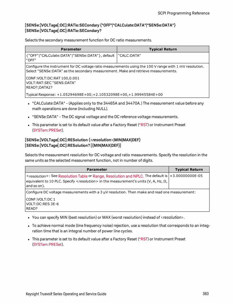
[SENSe:]VOLTage[:DC]:RATio:SECondary "OFF"|"CALCulate:DATA"|"SENSe:DATA"[SENSe:]VOLTage[:DC]:RATio:SECondary?
Selects the secondary measurement function for DC ratio measurements.
Parameter Typical Return
"OFF"|"CALCulate:DATA"|"SENSe:DATA", default"OFF"
"CALC:DATA"
Configure the instrument for DC voltage ratio measurements using the 100 V range with 1 mV resolution.Select "SENSe:DATA" as the secondary measurement. Make and retrieve measurements.
CONF:VOLT:DC:RAT 100,0.001VOLT:RAT:SEC "SENS:DATA"READ?;DATA2?
Typical Response: +1.05294698E+00;+2.10532098E+00,+1.99945584E+00
l "CALCulate:DATA" - (Applies only to the 34465A and 34470A.) The measurement value before anymath operations are done (including NULL).
l “SENSe:DATA” - The DC signal voltage and the DC reference voltage measurements.
l This parameter is set to its default value after a Factory Reset (*RST) or Instrument Preset(SYSTem:PRESet).
[SENSe:]VOLTage[:DC]:RESolution <resolution>|MIN|MAX|DEF[SENSe:]VOLTage[:DC]:RESolution? [MIN|MAX|DEF]
Selects the measurement resolution for DC voltage and ratio measurements. Specify the resolution in thesame units as the selected measurement function, not in number of digits.
Parameter Typical Return
<resolution>: See Resolution Table or Range, Resolution and NPLC. The default isequivalent to 10 PLC. Specify <resolution> in the measurement's units (V, A, Hz, Ω,and so on).
+3.00000000E-05
Configure DC voltage measurements with a 3 µV resolution. Then make and read one measurement:
CONF:VOLT:DC 1VOLT:DC:RES 3E-6READ?
l You can specify MIN (best resolution) or MAX (worst resolution) instead of <resolution>.
l To achieve normal mode (line frequency noise) rejection, use a resolution that corresponds to an integ-ration time that is an integral number of power line cycles.
l This parameter is set to its default value after a Factory Reset (*RST) or Instrument Preset(SYSTem:PRESet).
Keysight Truevolt Series Operating and Service Guide 383
SCPI Programming Reference
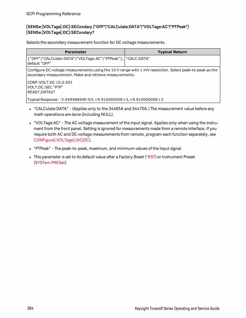
[SENSe:]VOLTage[:DC]:SECondary "OFF"|"CALCulate:DATA"|"VOLTage:AC"|"PTPeak"[SENSe:]VOLTage[:DC]:SECondary?
Selects the secondary measurement function for DC voltage measurements.
Parameter Typical Return
"OFF"|"CALCulate:DATA"|"VOLTage:AC"|"PTPeak",default "OFF"
"CALC:DATA"
Configure DC voltage measurements using the 10 V range with 1 mV resolution. Select peak-to-peak as thesecondary measurement. Make and retrieve measurements.
CONF:VOLT:DC 10,0.001VOLT:DC:SEC "PTP"READ?;DATA2?
Typical Response: -3.44948894E-03;+9.91000000E+3,+9.91000000E+3
l "CALCulate:DATA" - (Applies only to the 34465A and 34470A.) The measurement value before anymath operations are done (including NULL).
l "VOLTage:AC" - The AC voltage measurement of the input signal. Applies only when using the instru-ment from the front panel. Setting is ignored for measurements made from a remote interface. If yourequire both AC and DC voltage measurements from remote, program each function separately, seeCONFigure[:VOLTage]:AC|DC.
l "PTPeak" - The peak-to-peak, maximum, and minimum values of the input signal.
l This parameter is set to its default value after a Factory Reset (*RST) or Instrument Preset(SYSTem:PRESet).
SCPI Programming Reference
384 Keysight Truevolt Series Operating and Service Guide
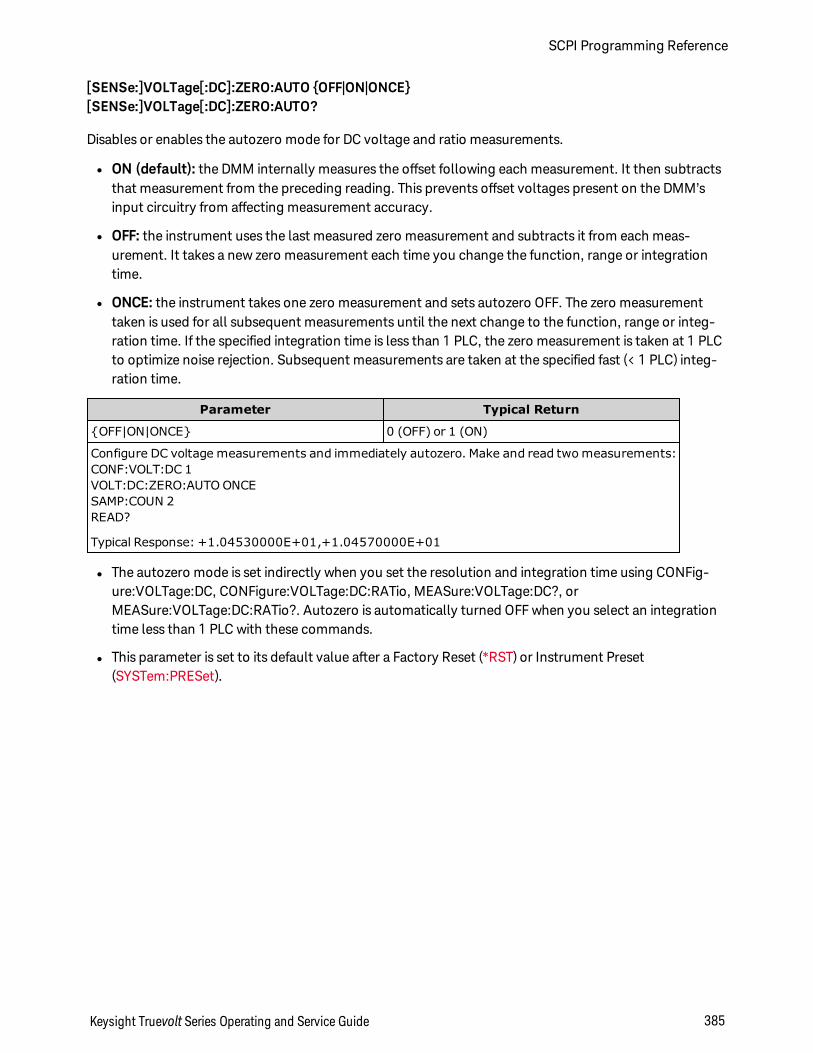
[SENSe:]VOLTage[:DC]:ZERO:AUTO OFF|ON|ONCE[SENSe:]VOLTage[:DC]:ZERO:AUTO?
Disables or enables the autozero mode for DC voltage and ratio measurements.
l ON (default): the DMM internally measures the offset following each measurement. It then subtractsthat measurement from the preceding reading. This prevents offset voltages present on the DMM’sinput circuitry from affecting measurement accuracy.
l OFF: the instrument uses the last measured zero measurement and subtracts it from each meas-urement. It takes a new zero measurement each time you change the function, range or integrationtime.
l ONCE: the instrument takes one zero measurement and sets autozero OFF. The zero measurementtaken is used for all subsequent measurements until the next change to the function, range or integ-ration time. If the specified integration time is less than 1 PLC, the zero measurement is taken at 1 PLCto optimize noise rejection. Subsequent measurements are taken at the specified fast (< 1 PLC) integ-ration time.
Parameter Typical Return
OFF|ON|ONCE 0 (OFF) or 1 (ON)
Configure DC voltage measurements and immediately autozero. Make and read two measurements:CONF:VOLT:DC 1VOLT:DC:ZERO:AUTO ONCESAMP:COUN 2READ?
Typical Response: +1.04530000E+01,+1.04570000E+01
l The autozero mode is set indirectly when you set the resolution and integration time using CONFig-ure:VOLTage:DC, CONFigure:VOLTage:DC:RATio, MEASure:VOLTage:DC?, orMEASure:VOLTage:DC:RATio?. Autozero is automatically turned OFF when you select an integrationtime less than 1 PLC with these commands.
l This parameter is set to its default value after a Factory Reset (*RST) or Instrument Preset(SYSTem:PRESet).
Keysight Truevolt Series Operating and Service Guide 385
SCPI Programming Reference
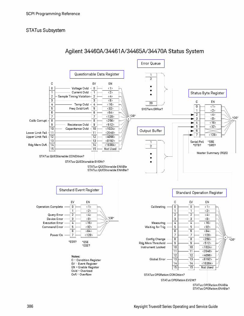
STATus Subsystem
SCPI Programming Reference
386 Keysight Truevolt Series Operating and Service Guide
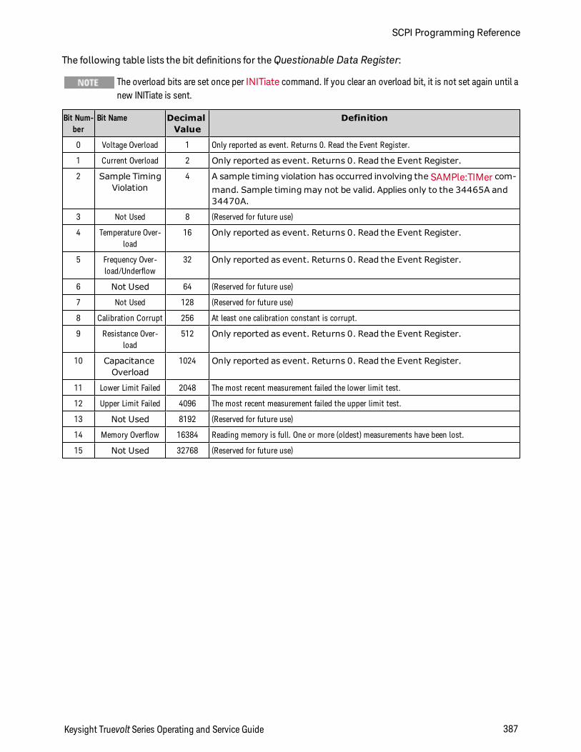
The following table lists the bit definitions for theQuestionable Data Register:
The overload bits are set once per INITiate command. If you clear an overload bit, it is not set again until anew INITiate is sent.
Bit Num-ber
Bit Name DecimalValue
Definition
0 Voltage Overload 1 Only reported as event. Returns 0. Read the Event Register.
1 Current Overload 2 Only reported as event. Returns 0. Read the Event Register.
2 Sample TimingViolation
4 A sample timing violation has occurred involving the SAMPle:TIMer com-mand. Sample timing may not be valid. Applies only to the 34465A and34470A.
3 Not Used 8 (Reserved for future use)
4 Temperature Over-load
16 Only reported as event. Returns 0. Read the Event Register.
5 Frequency Over-load/Underflow
32 Only reported as event. Returns 0. Read the Event Register.
6 Not Used 64 (Reserved for future use)
7 Not Used 128 (Reserved for future use)
8 Calibration Corrupt 256 At least one calibration constant is corrupt.
9 Resistance Over-load
512 Only reported as event. Returns 0. Read the Event Register.
10 CapacitanceOverload
1024 Only reported as event. Returns 0. Read the Event Register.
11 Lower Limit Failed 2048 The most recent measurement failed the lower limit test.
12 Upper Limit Failed 4096 The most recent measurement failed the upper limit test.
13 Not Used 8192 (Reserved for future use)
14 Memory Overflow 16384 Reading memory is full. One or more (oldest) measurements have been lost.
15 Not Used 32768 (Reserved for future use)
Keysight Truevolt Series Operating and Service Guide 387
SCPI Programming Reference
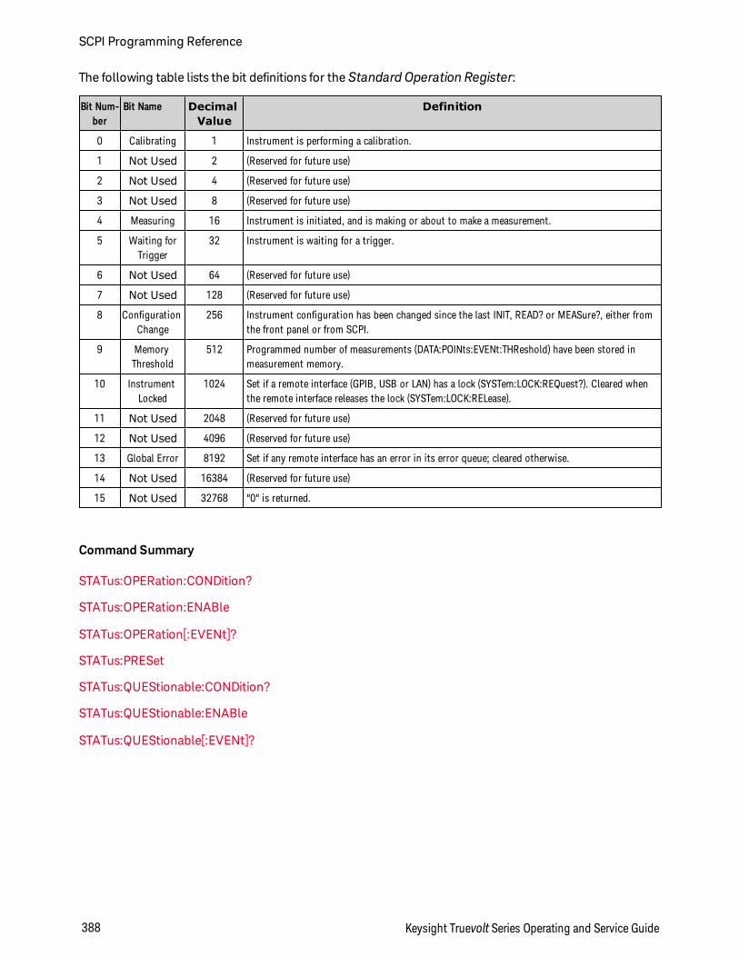
The following table lists the bit definitions for the Standard Operation Register:
Bit Num-ber
Bit Name DecimalValue
Definition
0 Calibrating 1 Instrument is performing a calibration.
1 Not Used 2 (Reserved for future use)
2 Not Used 4 (Reserved for future use)
3 Not Used 8 (Reserved for future use)
4 Measuring 16 Instrument is initiated, and is making or about to make a measurement.
5 Waiting forTrigger
32 Instrument is waiting for a trigger.
6 Not Used 64 (Reserved for future use)
7 Not Used 128 (Reserved for future use)
8 ConfigurationChange
256 Instrument configuration has been changed since the last INIT, READ? or MEASure?, either fromthe front panel or from SCPI.
9 MemoryThreshold
512 Programmed number of measurements (DATA:POINts:EVENt:THReshold) have been stored inmeasurement memory.
10 InstrumentLocked
1024 Set if a remote interface (GPIB, USB or LAN) has a lock (SYSTem:LOCK:REQuest?). Cleared whenthe remote interface releases the lock (SYSTem:LOCK:RELease).
11 Not Used 2048 (Reserved for future use)
12 Not Used 4096 (Reserved for future use)
13 Global Error 8192 Set if any remote interface has an error in its error queue; cleared otherwise.
14 Not Used 16384 (Reserved for future use)
15 Not Used 32768 "0" is returned.
Command Summary
STATus:OPERation:CONDition?
STATus:OPERation:ENABle
STATus:OPERation[:EVENt]?
STATus:PRESet
STATus:QUEStionable:CONDition?
STATus:QUEStionable:ENABle
STATus:QUEStionable[:EVENt]?
SCPI Programming Reference
388 Keysight Truevolt Series Operating and Service Guide
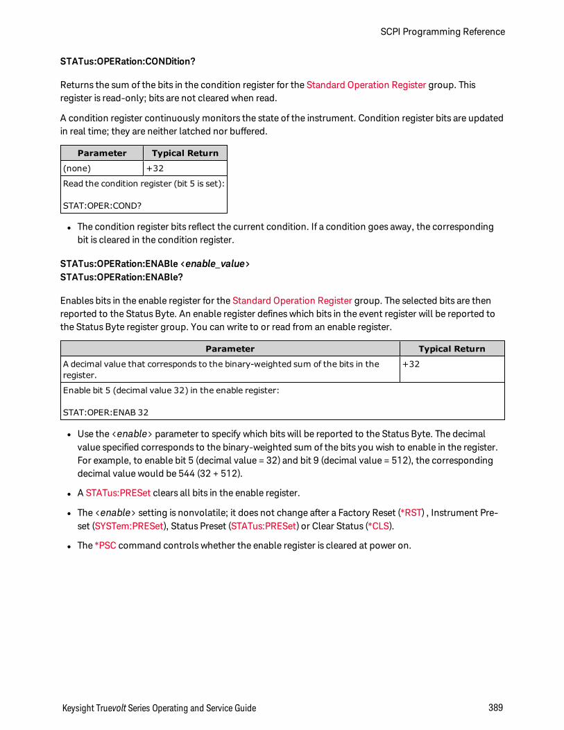
STATus:OPERation:CONDition?
Returns the sum of the bits in the condition register for the Standard Operation Register group. Thisregister is read-only; bits are not cleared when read.
A condition register continuously monitors the state of the instrument. Condition register bits are updatedin real time; they are neither latched nor buffered.
Parameter Typical Return
(none) +32
Read the condition register (bit 5 is set):
STAT:OPER:COND?
l The condition register bits reflect the current condition. If a condition goes away, the correspondingbit is cleared in the condition register.
STATus:OPERation:ENABle <enable_value>STATus:OPERation:ENABle?
Enables bits in the enable register for the Standard Operation Register group. The selected bits are thenreported to the Status Byte. An enable register defines which bits in the event register will be reported tothe Status Byte register group. You can write to or read from an enable register.
Parameter Typical Return
A decimal value that corresponds to the binary-weighted sum of the bits in theregister.
+32
Enable bit 5 (decimal value 32) in the enable register:
STAT:OPER:ENAB 32
l Use the <enable> parameter to specify which bits will be reported to the Status Byte. The decimalvalue specified corresponds to the binary-weighted sum of the bits you wish to enable in the register.For example, to enable bit 5 (decimal value = 32) and bit 9 (decimal value = 512), the correspondingdecimal value would be 544 (32 + 512).
l A STATus:PRESet clears all bits in the enable register.
l The <enable> setting is nonvolatile; it does not change after a Factory Reset (*RST) , Instrument Pre-set (SYSTem:PRESet), Status Preset (STATus:PRESet) or Clear Status (*CLS).
l The *PSC command controls whether the enable register is cleared at power on.
Keysight Truevolt Series Operating and Service Guide 389
SCPI Programming Reference
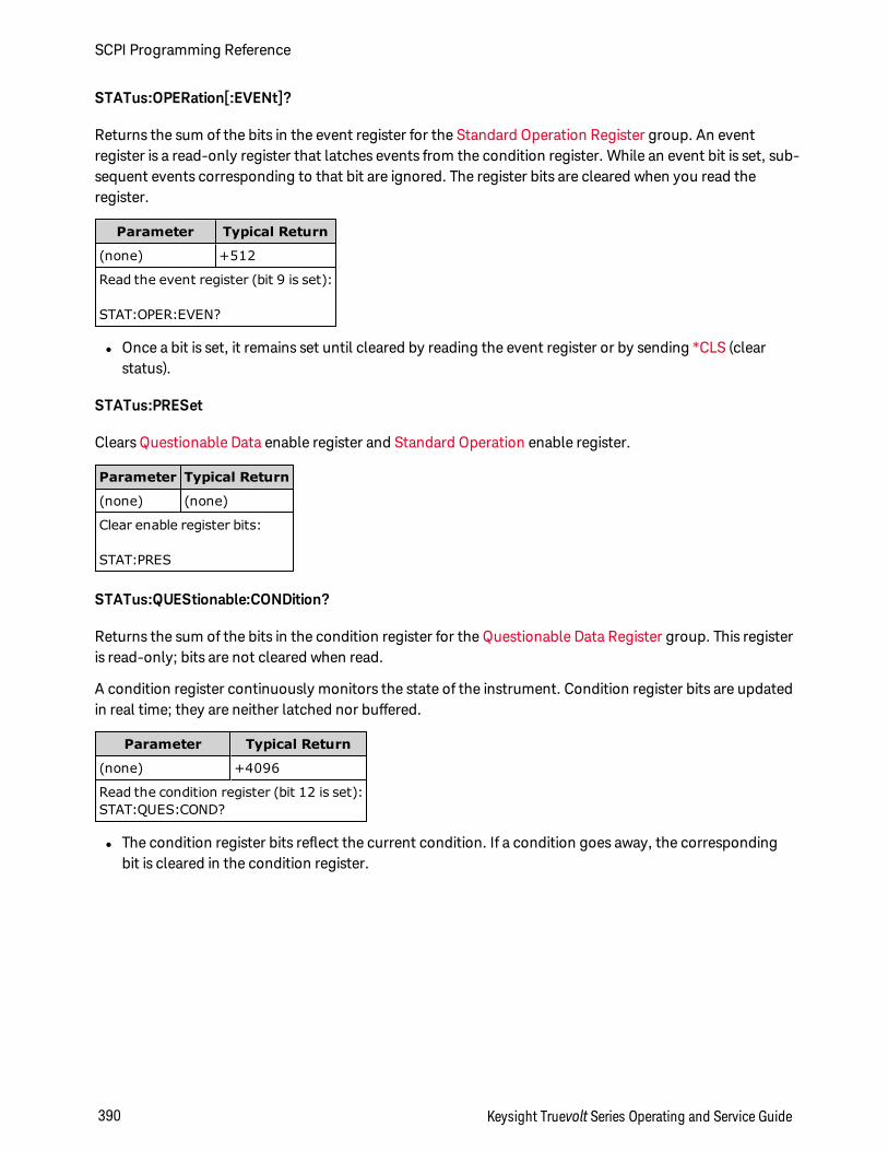
STATus:OPERation[:EVENt]?
Returns the sum of the bits in the event register for the Standard Operation Register group. An eventregister is a read-only register that latches events from the condition register. While an event bit is set, sub-sequent events corresponding to that bit are ignored. The register bits are cleared when you read theregister.
Parameter Typical Return
(none) +512
Read the event register (bit 9 is set):
STAT:OPER:EVEN?
l Once a bit is set, it remains set until cleared by reading the event register or by sending *CLS (clearstatus).
STATus:PRESet
Clears Questionable Data enable register and Standard Operation enable register.
Parameter Typical Return
(none) (none)
Clear enable register bits:
STAT:PRES
STATus:QUEStionable:CONDition?
Returns the sum of the bits in the condition register for the Questionable Data Register group. This registeris read-only; bits are not cleared when read.
A condition register continuously monitors the state of the instrument. Condition register bits are updatedin real time; they are neither latched nor buffered.
Parameter Typical Return
(none) +4096
Read the condition register (bit 12 is set):STAT:QUES:COND?
l The condition register bits reflect the current condition. If a condition goes away, the correspondingbit is cleared in the condition register.
SCPI Programming Reference
390 Keysight Truevolt Series Operating and Service Guide
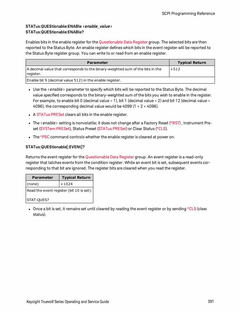
STATus:QUEStionable:ENABle <enable_value>STATus:QUEStionable:ENABle?
Enables bits in the enable register for the Questionable Data Register group. The selected bits are thenreported to the Status Byte. An enable register defines which bits in the event register will be reported tothe Status Byte register group. You can write to or read from an enable register.
Parameter Typical Return
A decimal value that corresponds to the binary-weighted sum of the bits in theregister.
+512
Enable bit 9 (decimal value 512) in the enable register.
l Use the <enable> parameter to specify which bits will be reported to the Status Byte. The decimalvalue specified corresponds to the binary-weighted sum of the bits you wish to enable in the register.For example, to enable bit 0 (decimal value = 1), bit 1 (decimal value = 2) and bit 12 (decimal value =4096), the corresponding decimal value would be 4099 (1 + 2 + 4096).
l A STATus:PRESet clears all bits in the enable register.
l The <enable> setting is nonvolatile; it does not change after a Factory Reset (*RST) , Instrument Pre-set (SYSTem:PRESet), Status Preset (STATus:PRESet) or Clear Status (*CLS).
l The *PSC command controls whether the enable register is cleared at power on.
STATus:QUEStionable[:EVENt]?
Returns the event register for the Questionable Data Register group. An event register is a read-onlyregister that latches events from the condition register. While an event bit is set, subsequent events cor-responding to that bit are ignored. The register bits are cleared when you read the register.
Parameter Typical Return
(none) +1024
Read the event register (bit 10 is set):
STAT:QUES?
l Once a bit is set, it remains set until cleared by reading the event register or by sending *CLS (clearstatus).
Keysight Truevolt Series Operating and Service Guide 391
SCPI Programming Reference
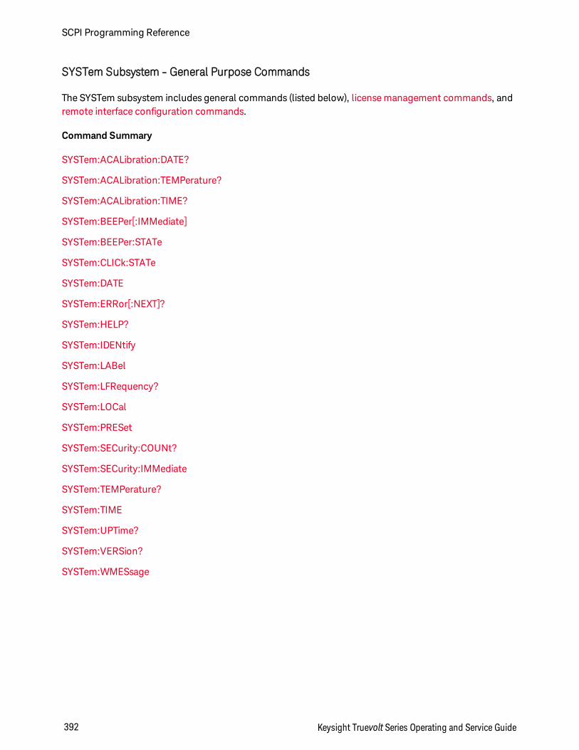
SYSTem Subsystem - General Purpose Commands
The SYSTem subsystem includes general commands (listed below), license management commands, andremote interface configuration commands.
Command Summary
SYSTem:ACALibration:DATE?
SYSTem:ACALibration:TEMPerature?
SYSTem:ACALibration:TIME?
SYSTem:BEEPer[:IMMediate]
SYSTem:BEEPer:STATe
SYSTem:CLICk:STATe
SYSTem:DATE
SYSTem:ERRor[:NEXT]?
SYSTem:HELP?
SYSTem:IDENtify
SYSTem:LABel
SYSTem:LFRequency?
SYSTem:LOCal
SYSTem:PRESet
SYSTem:SECurity:COUNt?
SYSTem:SECurity:IMMediate
SYSTem:TEMPerature?
SYSTem:TIME
SYSTem:UPTime?
SYSTem:VERSion?
SYSTem:WMESsage
SCPI Programming Reference
392 Keysight Truevolt Series Operating and Service Guide
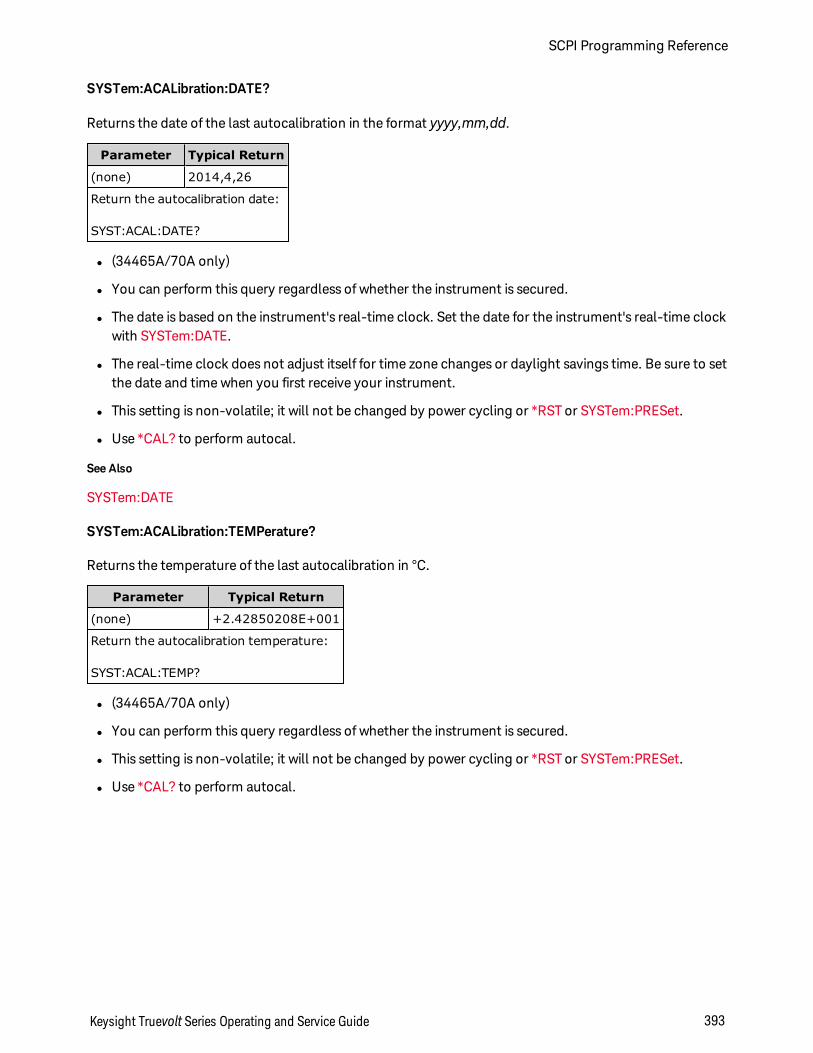
SYSTem:ACALibration:DATE?
Returns the date of the last autocalibration in the format yyyy,mm,dd.
Parameter Typical Return
(none) 2014,4,26
Return the autocalibration date:
SYST:ACAL:DATE?
l (34465A/70A only)
l You can perform this query regardless of whether the instrument is secured.
l The date is based on the instrument's real-time clock. Set the date for the instrument's real-time clockwith SYSTem:DATE.
l The real-time clock does not adjust itself for time zone changes or daylight savings time. Be sure to setthe date and time when you first receive your instrument.
l This setting is non-volatile; it will not be changed by power cycling or *RST or SYSTem:PRESet.
l Use *CAL? to perform autocal.
See Also
SYSTem:DATE
SYSTem:ACALibration:TEMPerature?
Returns the temperature of the last autocalibration in °C.
Parameter Typical Return
(none) +2.42850208E+001
Return the autocalibration temperature:
SYST:ACAL:TEMP?
l (34465A/70A only)
l You can perform this query regardless of whether the instrument is secured.
l This setting is non-volatile; it will not be changed by power cycling or *RST or SYSTem:PRESet.
l Use *CAL? to perform autocal.
Keysight Truevolt Series Operating and Service Guide 393
SCPI Programming Reference
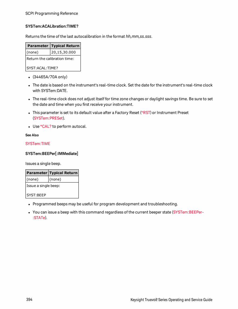
SYSTem:ACALibration:TIME?
Returns the time of the last autocalibration in the format hh,mm,ss.sss.
Parameter Typical Return
(none) 20,15,30.000
Return the calibration time:
SYST:ACAL:TIME?
l (34465A/70A only)
l The date is based on the instrument's real-time clock. Set the date for the instrument's real-time clockwith SYSTem:DATE.
l The real-time clock does not adjust itself for time zone changes or daylight savings time. Be sure to setthe date and time when you first receive your instrument.
l This parameter is set to its default value after a Factory Reset (*RST) or Instrument Preset(SYSTem:PRESet).
l Use *CAL? to perform autocal.
See Also
SYSTem:TIME
SYSTem:BEEPer[:IMMediate]
Issues a single beep.
Parameter Typical Return
(none) (none)
Issue a single beep:
SYST:BEEP
l Programmed beeps may be useful for program development and troubleshooting.
l You can issue a beep with this command regardless of the current beeper state (SYSTem:BEEPer-:STATe).
SCPI Programming Reference
394 Keysight Truevolt Series Operating and Service Guide
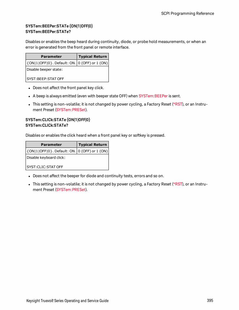
SYSTem:BEEPer:STATe ON|1|OFF|0SYSTem:BEEPer:STATe?
Disables or enables the beep heard during continuity, diode, or probe hold measurements, or when anerror is generated from the front panel or remote interface.
Parameter Typical Return
ON|1|OFF|0. Default: ON. 0 (OFF) or 1 (ON)
Disable beeper state:
SYST:BEEP:STAT OFF
l Does not affect the front panel key click.
l A beep is always emitted (even with beeper state OFF) when SYSTem:BEEPer is sent.
l This setting is non-volatile; it is not changed by power cycling, a Factory Reset (*RST), or an Instru-ment Preset (SYSTem:PRESet).
SYSTem:CLICk:STATe ON|1|OFF|0SYSTem:CLICk:STATe?
Disables or enables the click heard when a front panel key or softkey is pressed.
Parameter Typical Return
ON|1|OFF|0. Default: ON. 0 (OFF) or 1 (ON)
Disable keyboard click:
SYST:CLIC:STAT OFF
l Does not affect the beeper for diode and continuity tests, errors and so on.
l This setting is non-volatile; it is not changed by power cycling, a Factory Reset (*RST), or an Instru-ment Preset (SYSTem:PRESet).
Keysight Truevolt Series Operating and Service Guide 395
SCPI Programming Reference
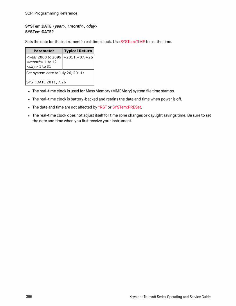
SYSTem:DATE <year>, <month>, <day>SYSTem:DATE?
Sets the date for the instrument's real-time clock. Use SYSTem:TIME to set the time.
Parameter Typical Return
<year 2000 to 2099<month> 1 to 12<day> 1 to 31
+2011,+07,+26
Set system date to July 26, 2011:
SYST:DATE 2011, 7,26
l The real-time clock is used for Mass Memory (MMEMory) system file time stamps.
l The real-time clock is battery-backed and retains the date and time when power is off.
l The date and time are not affected by *RST or SYSTem:PRESet.
l The real-time clock does not adjust itself for time zone changes or daylight savings time. Be sure to setthe date and time when you first receive your instrument.
SCPI Programming Reference
396 Keysight Truevolt Series Operating and Service Guide
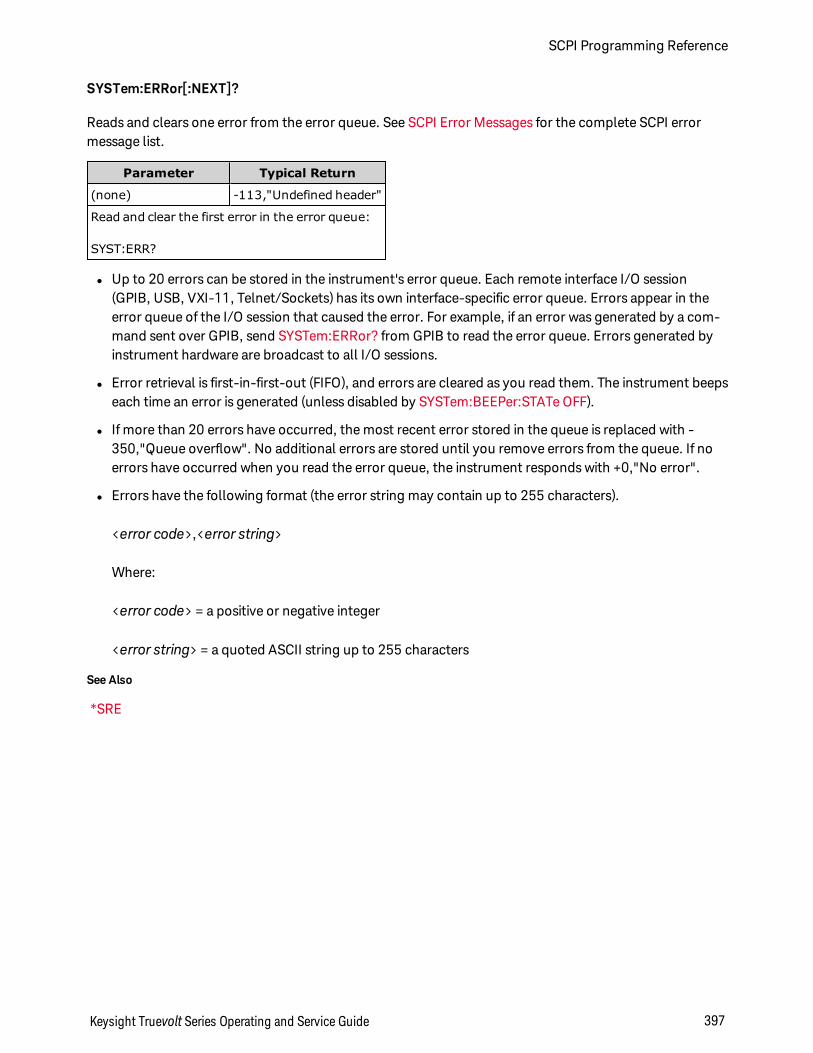
SYSTem:ERRor[:NEXT]?
Reads and clears one error from the error queue. See SCPI Error Messages for the complete SCPI errormessage list.
Parameter Typical Return
(none) -113,"Undefined header"
Read and clear the first error in the error queue:
SYST:ERR?
l Up to 20 errors can be stored in the instrument's error queue. Each remote interface I/O session(GPIB, USB, VXI-11, Telnet/Sockets) has its own interface-specific error queue. Errors appear in theerror queue of the I/O session that caused the error. For example, if an error was generated by a com-mand sent over GPIB, send SYSTem:ERRor? from GPIB to read the error queue. Errors generated byinstrument hardware are broadcast to all I/O sessions.
l Error retrieval is first-in-first-out (FIFO), and errors are cleared as you read them. The instrument beepseach time an error is generated (unless disabled by SYSTem:BEEPer:STATe OFF).
l If more than 20 errors have occurred, the most recent error stored in the queue is replaced with -350,"Queue overflow". No additional errors are stored until you remove errors from the queue. If noerrors have occurred when you read the error queue, the instrument responds with +0,"No error".
l Errors have the following format (the error string may contain up to 255 characters).
<error code>,<error string>
Where:
<error code> = a positive or negative integer
<error string> = a quoted ASCII string up to 255 characters
See Also
*SRE
Keysight Truevolt Series Operating and Service Guide 397
SCPI Programming Reference
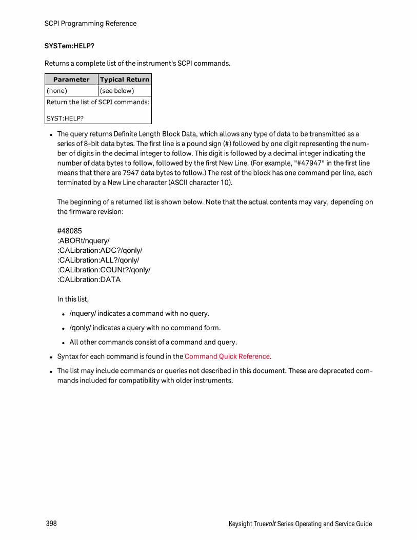
SYSTem:HELP?
Returns a complete list of the instrument's SCPI commands.
Parameter Typical Return
(none) (see below)
Return the list of SCPI commands:
SYST:HELP?
l The query returns Definite Length Block Data, which allows any type of data to be transmitted as aseries of 8-bit data bytes. The first line is a pound sign (#) followed by one digit representing the num-ber of digits in the decimal integer to follow. This digit is followed by a decimal integer indicating thenumber of data bytes to follow, followed by the first New Line. (For example, "#47947" in the first linemeans that there are 7947 data bytes to follow.) The rest of the block has one command per line, eachterminated by a New Line character (ASCII character 10).
The beginning of a returned list is shown below. Note that the actual contents may vary, depending onthe firmware revision:
#48085:ABORt/nquery/:CALibration:ADC?/qonly/:CALibration:ALL?/qonly/:CALibration:COUNt?/qonly/:CALibration:DATA
In this list,
l /nquery/ indicates a command with no query.
l /qonly/ indicates a query with no command form.
l All other commands consist of a command and query.
l Syntax for each command is found in the Command Quick Reference.
l The list may include commands or queries not described in this document. These are deprecated com-mands included for compatibility with older instruments.
SCPI Programming Reference
398 Keysight Truevolt Series Operating and Service Guide
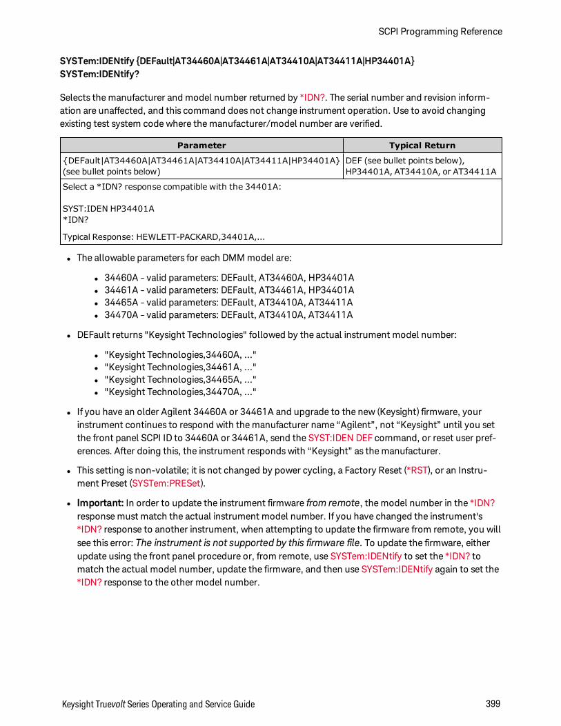
SYSTem:IDENtify DEFault|AT34460A|AT34461A|AT34410A|AT34411A|HP34401ASYSTem:IDENtify?
Selects the manufacturer and model number returned by *IDN?. The serial number and revision inform-ation are unaffected, and this command does not change instrument operation. Use to avoid changingexisting test system code where the manufacturer/model number are verified.
Parameter Typical Return
DEFault|AT34460A|AT34461A|AT34410A|AT34411A|HP34401A(see bullet points below)
DEF (see bullet points below),HP34401A, AT34410A, or AT34411A
Select a *IDN? response compatible with the 34401A:
SYST:IDEN HP34401A*IDN?
Typical Response: HEWLETT-PACKARD,34401A,...
l The allowable parameters for each DMM model are:
l 34460A - valid parameters: DEFault, AT34460A, HP34401Al 34461A - valid parameters: DEFault, AT34461A, HP34401Al 34465A - valid parameters: DEFault, AT34410A, AT34411Al 34470A - valid parameters: DEFault, AT34410A, AT34411A
l DEFault returns "Keysight Technologies" followed by the actual instrument model number:
l "Keysight Technologies,34460A, ..."l "Keysight Technologies,34461A, ..."l "Keysight Technologies,34465A, ..."l "Keysight Technologies,34470A, ..."
l If you have an older Agilent 34460A or 34461A and upgrade to the new (Keysight) firmware, yourinstrument continues to respond with the manufacturer name “Agilent”, not “Keysight” until you setthe front panel SCPI ID to 34460A or 34461A, send the SYST:IDEN DEF command, or reset user pref-erences. After doing this, the instrument responds with “Keysight” as the manufacturer.
l This setting is non-volatile; it is not changed by power cycling, a Factory Reset (*RST), or an Instru-ment Preset (SYSTem:PRESet).
l Important: In order to update the instrument firmware from remote, the model number in the *IDN?response must match the actual instrument model number. If you have changed the instrument's*IDN? response to another instrument, when attempting to update the firmware from remote, you willsee this error: The instrument is not supported by this firmware file. To update the firmware, eitherupdate using the front panel procedure or, from remote, use SYSTem:IDENtify to set the *IDN? tomatch the actual model number, update the firmware, and then use SYSTem:IDENtify again to set the*IDN? response to the other model number.
Keysight Truevolt Series Operating and Service Guide 399
SCPI Programming Reference
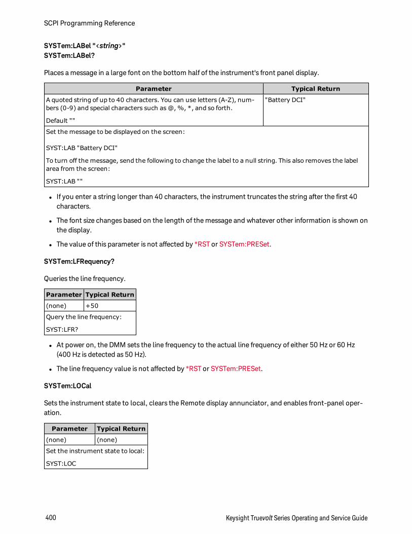
SYSTem:LABel "<string>"SYSTem:LABel?
Places a message in a large font on the bottom half of the instrument's front panel display.
Parameter Typical Return
A quoted string of up to 40 characters. You can use letters (A-Z), num-bers (0-9) and special characters such as @, %, *, and so forth.
Default ""
"Battery DCI"
Set the message to be displayed on the screen:
SYST:LAB "Battery DCI"
To turn off the message, send the following to change the label to a null string. This also removes the labelarea from the screen:
SYST:LAB ""
l If you enter a string longer than 40 characters, the instrument truncates the string after the first 40characters.
l The font size changes based on the length of the message and whatever other information is shown onthe display.
l The value of this parameter is not affected by *RST or SYSTem:PRESet.
SYSTem:LFRequency?
Queries the line frequency.
Parameter Typical Return
(none) +50
Query the line frequency:
SYST:LFR?
l At power on, the DMM sets the line frequency to the actual line frequency of either 50 Hz or 60 Hz(400 Hz is detected as 50 Hz).
l The line frequency value is not affected by *RST or SYSTem:PRESet.
SYSTem:LOCal
Sets the instrument state to local, clears the Remote display annunciator, and enables front-panel oper-ation.
Parameter Typical Return
(none) (none)
Set the instrument state to local:
SYST:LOC
SCPI Programming Reference
400 Keysight Truevolt Series Operating and Service Guide
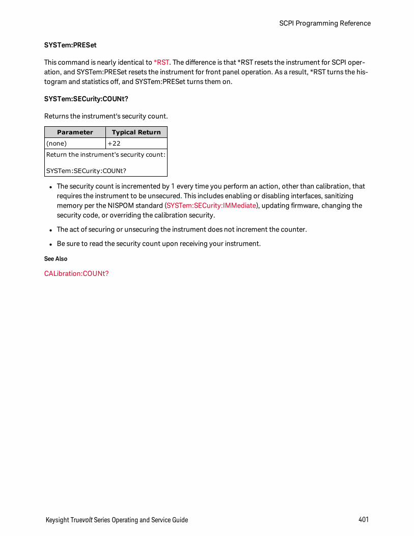
SYSTem:PRESet
This command is nearly identical to *RST. The difference is that *RST resets the instrument for SCPI oper-ation, and SYSTem:PRESet resets the instrument for front panel operation. As a result, *RST turns the his-togram and statistics off, and SYSTem:PRESet turns them on.
SYSTem:SECurity:COUNt?
Returns the instrument's security count.
Parameter Typical Return
(none) +22
Return the instrument's security count:
SYSTem:SECurity:COUNt?
l The security count is incremented by 1 every time you perform an action, other than calibration, thatrequires the instrument to be unsecured. This includes enabling or disabling interfaces, sanitizingmemory per the NISPOM standard (SYSTem:SECurity:IMMediate), updating firmware, changing thesecurity code, or overriding the calibration security.
l The act of securing or unsecuring the instrument does not increment the counter.
l Be sure to read the security count upon receiving your instrument.
See Also
CALibration:COUNt?
Keysight Truevolt Series Operating and Service Guide 401
SCPI Programming Reference
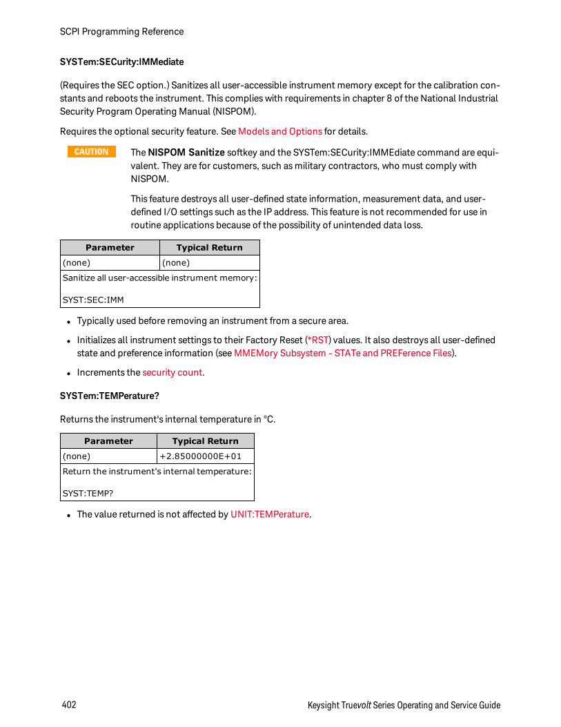
SYSTem:SECurity:IMMediate
(Requires the SEC option.) Sanitizes all user-accessible instrument memory except for the calibration con-stants and reboots the instrument. This complies with requirements in chapter 8 of the National IndustrialSecurity Program Operating Manual (NISPOM).
Requires the optional security feature. See Models and Options for details.
The NISPOM Sanitize softkey and the SYSTem:SECurity:IMMEdiate command are equi-valent. They are for customers, such as military contractors, who must comply withNISPOM.
This feature destroys all user-defined state information, measurement data, and user-defined I/O settings such as the IP address. This feature is not recommended for use inroutine applications because of the possibility of unintended data loss.
Parameter Typical Return
(none) (none)
Sanitize all user-accessible instrument memory:
SYST:SEC:IMM
l Typically used before removing an instrument from a secure area.
l Initializes all instrument settings to their Factory Reset (*RST) values. It also destroys all user-definedstate and preference information (see MMEMory Subsystem - STATe and PREFerence Files).
l Increments the security count.
SYSTem:TEMPerature?
Returns the instrument's internal temperature in °C.
Parameter Typical Return
(none) +2.85000000E+01
Return the instrument's internal temperature:
SYST:TEMP?
l The value returned is not affected by UNIT:TEMPerature.
SCPI Programming Reference
402 Keysight Truevolt Series Operating and Service Guide
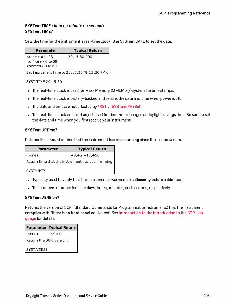
SYSTem:TIME <hour>, <minute>, <second>SYSTem:TIME?
Sets the time for the instrument's real-time clock. Use SYSTem:DATE to set the date.
Parameter Typical Return
<hour> 0 to 23<minute> 0 to 59<second> 0 to 60
20,15,30.000
Set instrument time to 20:15:30 (8:15:30 PM):
SYST:TIME 20,15,30
l The real-time clock is used for Mass Memory (MMEMory) system file time stamps.
l The real-time clock is battery-backed and retains the date and time when power is off.
l The date and time are not affected by *RST or SYSTem:PRESet.
l The real-time clock does not adjust itself for time zone changes or daylight savings time. Be sure to setthe date and time when you first receive your instrument.
SYSTem:UPTime?
Returns the amount of time that the instrument has been running since the last power-on.
Parameter Typical Return
(none) +8,+2,+13,+50
Return time that the instrument has been running:
SYST:UPT?
l Typically used to verify that the instrument is warmed up sufficiently before calibration.
l The numbers returned indicate days, hours, minutes, and seconds, respectively.
SYSTem:VERSion?
Returns the version of SCPI (Standard Commands for Programmable Instruments) that the instrumentcomplies with. There is no front panel equivalent. See Introduction to the Introduction to the SCPI Lan-guage for details.
Parameter Typical Return
(none) 1994.0
Return the SCPI version:
SYST:VERS?
Keysight Truevolt Series Operating and Service Guide 403
SCPI Programming Reference
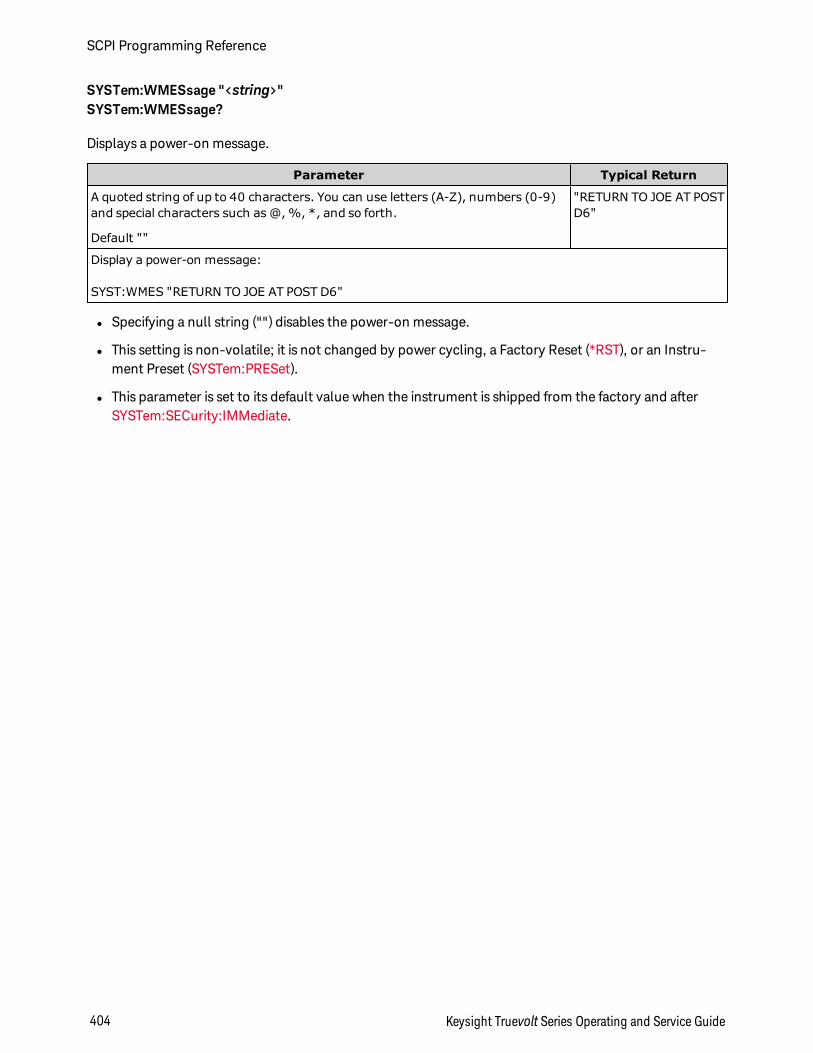
SYSTem:WMESsage "<string>"SYSTem:WMESsage?
Displays a power-on message.
Parameter Typical Return
A quoted string of up to 40 characters. You can use letters (A-Z), numbers (0-9)and special characters such as @, %, *, and so forth.
Default ""
"RETURN TO JOE AT POSTD6"
Display a power-on message:
SYST:WMES "RETURN TO JOE AT POST D6"
l Specifying a null string ("") disables the power-on message.
l This setting is non-volatile; it is not changed by power cycling, a Factory Reset (*RST), or an Instru-ment Preset (SYSTem:PRESet).
l This parameter is set to its default value when the instrument is shipped from the factory and afterSYSTem:SECurity:IMMediate.
SCPI Programming Reference
404 Keysight Truevolt Series Operating and Service Guide
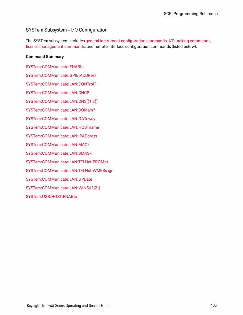
SYSTem Subsystem - I/O Configuration
The SYSTem subsystem includes general instrument configuration commands, I/O locking commands,license management commands, and remote interface configuration commands (listed below).
Command Summary
SYSTem:COMMunicate:ENABle
SYSTem:COMMunicate:GPIB:ADDRess
SYSTem:COMMunicate:LAN:CONTrol?
SYSTem:COMMunicate:LAN:DHCP
SYSTem:COMMunicate:LAN:DNS[1|2]
SYSTem:COMMunicate:LAN:DOMain?
SYSTem:COMMunicate:LAN:GATeway
SYSTem:COMMunicate:LAN:HOSTname
SYSTem:COMMunicate:LAN:IPADdress
SYSTem:COMMunicate:LAN:MAC?
SYSTem:COMMunicate:LAN:SMASk
SYSTem:COMMunicate:LAN:TELNet:PROMpt
SYSTem:COMMunicate:LAN:TELNet:WMESsage
SYSTem:COMMunicate:LAN:UPDate
SYSTem:COMMunicate:LAN:WINS[1|2]
SYSTem:USB:HOST:ENABle
Keysight Truevolt Series Operating and Service Guide 405
SCPI Programming Reference
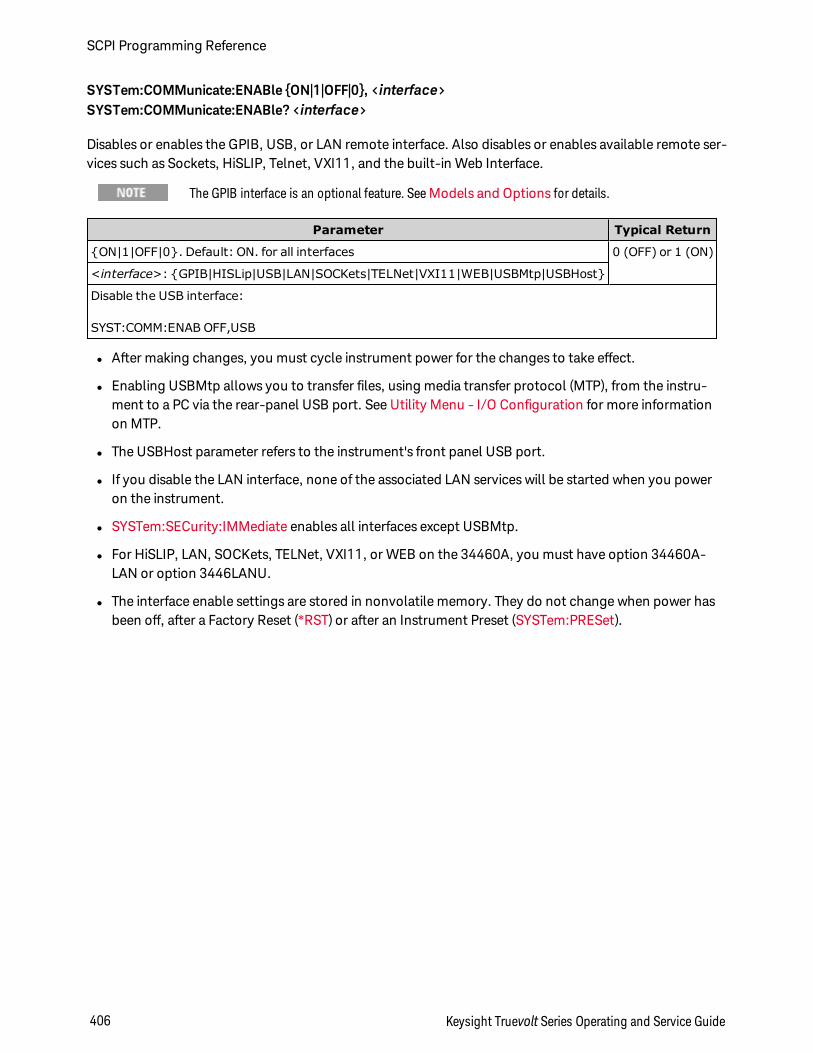
SYSTem:COMMunicate:ENABle ON|1|OFF|0, <interface>SYSTem:COMMunicate:ENABle? <interface>
Disables or enables the GPIB, USB, or LAN remote interface. Also disables or enables available remote ser-vices such as Sockets, HiSLIP, Telnet, VXI11, and the built-in Web Interface.
The GPIB interface is an optional feature. SeeModels and Options for details.
Parameter Typical Return
ON|1|OFF|0. Default: ON. for all interfaces 0 (OFF) or 1 (ON)
<interface>: GPIB|HISLip|USB|LAN|SOCKets|TELNet|VXI11|WEB|USBMtp|USBHost
Disable the USB interface:
SYST:COMM:ENAB OFF,USB
l After making changes, you must cycle instrument power for the changes to take effect.
l Enabling USBMtp allows you to transfer files, using media transfer protocol (MTP), from the instru-ment to a PC via the rear-panel USB port. See Utility Menu - I/O Configuration for more informationon MTP.
l The USBHost parameter refers to the instrument's front panel USB port.
l If you disable the LAN interface, none of the associated LAN services will be started when you poweron the instrument.
l SYSTem:SECurity:IMMediate enables all interfaces except USBMtp.
l For HiSLIP, LAN, SOCKets, TELNet, VXI11, or WEB on the 34460A, you must have option 34460A-LAN or option 3446LANU.
l The interface enable settings are stored in nonvolatile memory. They do not change when power hasbeen off, after a Factory Reset (*RST) or after an Instrument Preset (SYSTem:PRESet).
SCPI Programming Reference
406 Keysight Truevolt Series Operating and Service Guide
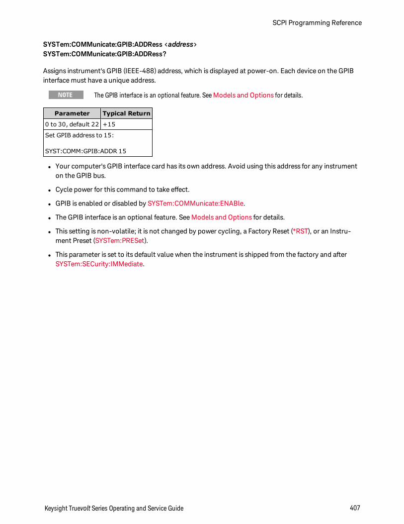
SYSTem:COMMunicate:GPIB:ADDRess <address>SYSTem:COMMunicate:GPIB:ADDRess?
Assigns instrument's GPIB (IEEE-488) address, which is displayed at power-on. Each device on the GPIBinterface must have a unique address.
The GPIB interface is an optional feature. SeeModels and Options for details.
Parameter Typical Return
0 to 30, default 22 +15
Set GPIB address to 15:
SYST:COMM:GPIB:ADDR 15
l Your computer's GPIB interface card has its own address. Avoid using this address for any instrumenton the GPIB bus.
l Cycle power for this command to take effect.
l GPIB is enabled or disabled by SYSTem:COMMunicate:ENABle.
l The GPIB interface is an optional feature. See Models and Options for details.
l This setting is non-volatile; it is not changed by power cycling, a Factory Reset (*RST), or an Instru-ment Preset (SYSTem:PRESet).
l This parameter is set to its default value when the instrument is shipped from the factory and afterSYSTem:SECurity:IMMediate.
Keysight Truevolt Series Operating and Service Guide 407
SCPI Programming Reference
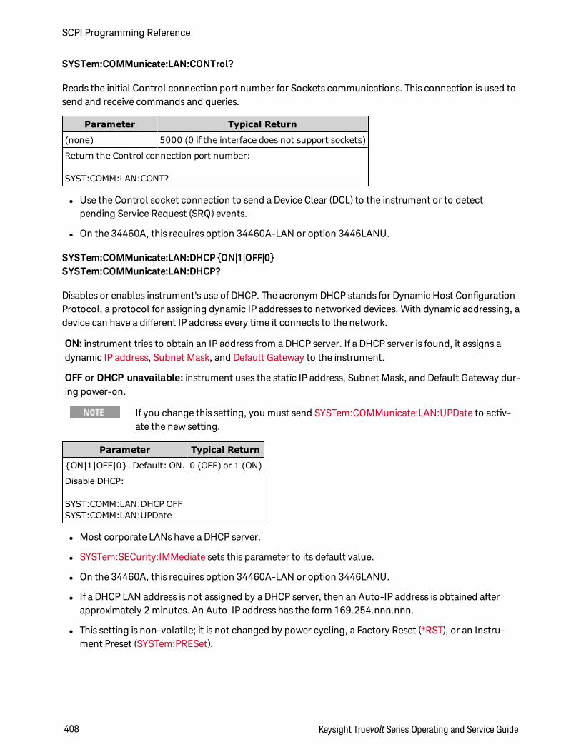
SYSTem:COMMunicate:LAN:CONTrol?
Reads the initial Control connection port number for Sockets communications. This connection is used tosend and receive commands and queries.
Parameter Typical Return
(none) 5000 (0 if the interface does not support sockets)
Return the Control connection port number:
SYST:COMM:LAN:CONT?
l Use the Control socket connection to send a Device Clear (DCL) to the instrument or to detectpending Service Request (SRQ) events.
l On the 34460A, this requires option 34460A-LAN or option 3446LANU.
SYSTem:COMMunicate:LAN:DHCP ON|1|OFF|0SYSTem:COMMunicate:LAN:DHCP?
Disables or enables instrument's use of DHCP. The acronym DHCP stands for Dynamic Host ConfigurationProtocol, a protocol for assigning dynamic IP addresses to networked devices. With dynamic addressing, adevice can have a different IP address every time it connects to the network.
ON: instrument tries to obtain an IP address from a DHCP server. If a DHCP server is found, it assigns adynamic IP address, Subnet Mask, and Default Gateway to the instrument.
OFF or DHCP unavailable: instrument uses the static IP address, Subnet Mask, and Default Gateway dur-ing power-on.
If you change this setting, you must send SYSTem:COMMunicate:LAN:UPDate to activ-ate the new setting.
Parameter Typical Return
ON|1|OFF|0. Default: ON. 0 (OFF) or 1 (ON)
Disable DHCP:
SYST:COMM:LAN:DHCP OFFSYST:COMM:LAN:UPDate
l Most corporate LANs have a DHCP server.
l SYSTem:SECurity:IMMediate sets this parameter to its default value.
l On the 34460A, this requires option 34460A-LAN or option 3446LANU.
l If a DHCP LAN address is not assigned by a DHCP server, then an Auto-IP address is obtained afterapproximately 2 minutes. An Auto-IP address has the form 169.254.nnn.nnn.
l This setting is non-volatile; it is not changed by power cycling, a Factory Reset (*RST), or an Instru-ment Preset (SYSTem:PRESet).
SCPI Programming Reference
408 Keysight Truevolt Series Operating and Service Guide
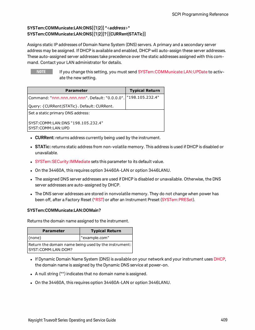
SYSTem:COMMunicate:LAN:DNS[1|2] "<address>"SYSTem:COMMunicate:LAN:DNS[1|2]? [CURRent|STATic]
Assigns static IP addresses of Domain Name System (DNS) servers. A primary and a secondary serveraddress may be assigned. If DHCP is available and enabled, DHCP will auto-assign these server addresses.These auto-assigned server addresses take precedence over the static addresses assigned with this com-mand. Contact your LAN administrator for details.
If you change this setting, you must send SYSTem:COMMunicate:LAN:UPDate to activ-ate the new setting.
Parameter Typical Return
Command: "nnn.nnn.nnn.nnn". Default: "0.0.0.0".
Query: CURRent|STATic. Default: CURRent.
"198.105.232.4"
Set a static primary DNS address:
SYST:COMM:LAN:DNS "198.105.232.4"SYST:COMM:LAN:UPD
l CURRent: returns address currently being used by the instrument.
l STATic: returns static address from non-volatile memory. This address is used if DHCP is disabled orunavailable.
l SYSTem:SECurity:IMMediate sets this parameter to its default value.
l On the 34460A, this requires option 34460A-LAN or option 3446LANU.
l The assigned DNS server addresses are used if DHCP is disabled or unavailable. Otherwise, the DNSserver addresses are auto-assigned by DHCP.
l The DNS server addresses are stored in nonvolatile memory. They do not change when power hasbeen off, after a Factory Reset (*RST) or after an Instrument Preset (SYSTem:PRESet).
SYSTem:COMMunicate:LAN:DOMain?
Returns the domain name assigned to the instrument.
Parameter Typical Return
(none) "example.com"
Return the domain name being used by the instrument:SYST:COMM:LAN:DOM?
l If Dynamic Domain Name System (DNS) is available on your network and your instrument uses DHCP,the domain name is assigned by the Dynamic DNS service at power-on.
l A null string ("") indicates that no domain name is assigned.
l On the 34460A, this requires option 34460A-LAN or option 3446LANU.
Keysight Truevolt Series Operating and Service Guide 409
SCPI Programming Reference
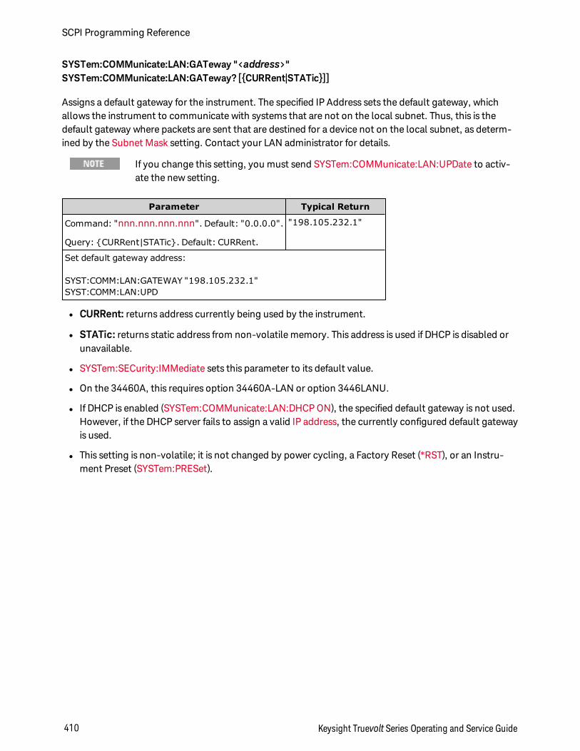
SYSTem:COMMunicate:LAN:GATeway "<address>"SYSTem:COMMunicate:LAN:GATeway? [CURRent|STATic]]
Assigns a default gateway for the instrument. The specified IP Address sets the default gateway, whichallows the instrument to communicate with systems that are not on the local subnet. Thus, this is thedefault gateway where packets are sent that are destined for a device not on the local subnet, as determ-ined by the Subnet Mask setting. Contact your LAN administrator for details.
If you change this setting, you must send SYSTem:COMMunicate:LAN:UPDate to activ-ate the new setting.
Parameter Typical Return
Command: "nnn.nnn.nnn.nnn". Default: "0.0.0.0".
Query: CURRent|STATic. Default: CURRent.
"198.105.232.1"
Set default gateway address:
SYST:COMM:LAN:GATEWAY "198.105.232.1"SYST:COMM:LAN:UPD
l CURRent: returns address currently being used by the instrument.
l STATic: returns static address from non-volatile memory. This address is used if DHCP is disabled orunavailable.
l SYSTem:SECurity:IMMediate sets this parameter to its default value.
l On the 34460A, this requires option 34460A-LAN or option 3446LANU.
l If DHCP is enabled (SYSTem:COMMunicate:LAN:DHCP ON), the specified default gateway is not used.However, if the DHCP server fails to assign a valid IP address, the currently configured default gatewayis used.
l This setting is non-volatile; it is not changed by power cycling, a Factory Reset (*RST), or an Instru-ment Preset (SYSTem:PRESet).
SCPI Programming Reference
410 Keysight Truevolt Series Operating and Service Guide
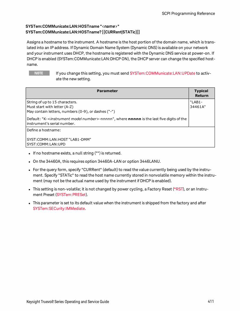
SYSTem:COMMunicate:LAN:HOSTname "<name>"SYSTem:COMMunicate:LAN:HOSTname? [CURRent|STATic]]
Assigns a hostname to the instrument. A hostname is the host portion of the domain name, which is trans-lated into an IP address. If Dynamic Domain Name System (Dynamic DNS) is available on your networkand your instrument uses DHCP, the hostname is registered with the Dynamic DNS service at power-on. IfDHCP is enabled (SYSTem:COMMunicate:LAN:DHCP ON), the DHCP server can change the specified host-name.
If you change this setting, you must send SYSTem:COMMunicate:LAN:UPDate to activ-ate the new setting.
Parameter TypicalReturn
String of up to 15 characters.Must start with letter (A-Z)May contain letters, numbers (0-9), or dashes ("-")
Default: "K-<instrument model number>-nnnnn", where nnnnn is the last five digits of theinstrument's serial number.
"LAB1-34461A"
Define a hostname:
SYST:COMM:LAN:HOST "LAB1-DMM"SYST:COMM:LAN:UPD
l If no hostname exists, a null string ("") is returned.
l On the 34460A, this requires option 34460A-LAN or option 3446LANU.
l For the query form, specify "CURRent" (default) to read the value currently being used by the instru-ment. Specify "STATic" to read the host name currently stored in nonvolatile memory within the instru-ment (may not be the actual name used by the instrument if DHCP is enabled).
l This setting is non-volatile; it is not changed by power cycling, a Factory Reset (*RST), or an Instru-ment Preset (SYSTem:PRESet).
l This parameter is set to its default value when the instrument is shipped from the factory and afterSYSTem:SECurity:IMMediate.
Keysight Truevolt Series Operating and Service Guide 411
SCPI Programming Reference
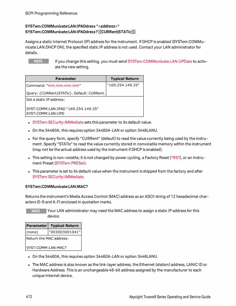
SYSTem:COMMunicate:LAN:IPADdress "<address>"SYSTem:COMMunicate:LAN:IPADdress? [CURRent|STATic]]
Assigns a static Internet Protocol (IP) address for the instrument. If DHCP is enabled (SYSTem:COMMu-nicate:LAN:DHCP ON), the specified static IP address is not used. Contact your LAN administrator fordetails.
If you change this setting, you must send SYSTem:COMMunicate:LAN:UPDate to activ-ate the new setting.
Parameter Typical Return
Command: "nnn.nnn.nnn.nnn"
Query: CURRent|STATic. Default: CURRent.
"169.254.149.35"
Set a static IP address:
SYST:COMM:LAN:IPAD "169.254.149.35"SYST:COMM:LAN:UPD
l SYSTem:SECurity:IMMediate sets this parameter to its default value.
l On the 34460A, this requires option 34460A-LAN or option 3446LANU.
l For the query form, specify "CURRent" (default) to read the value currently being used by the instru-ment. Specify "STATic" to read the value currently stored in nonvolatile memory within the instrument(may not be the actual address used by the instrument if DHCP is enabled).
l This setting is non-volatile; it is not changed by power cycling, a Factory Reset (*RST), or an Instru-ment Preset (SYSTem:PRESet).
l This parameter is set to its default value when the instrument is shipped from the factory and afterSYSTem:SECurity:IMMediate.
SYSTem:COMMunicate:LAN:MAC?
Returns the instrument's Media Access Control (MAC) address as an ASCII string of 12 hexadecimal char-acters (0-9 and A-F) enclosed in quotation marks.
Your LAN administrator may need the MAC address to assign a static IP address for thisdevice.
Parameter Typical Return
(none) "0030D3001041"
Return the MAC address:
SYST:COMM:LAN:MAC?
l On the 34460A, this requires option 34460A-LAN or option 3446LANU.
l The MAC address is also known as the link-layer address, the Ethernet (station) address, LANIC ID orHardware Address. This is an unchangeable 48-bit address assigned by the manufacturer to eachunique Internet device.
SCPI Programming Reference
412 Keysight Truevolt Series Operating and Service Guide
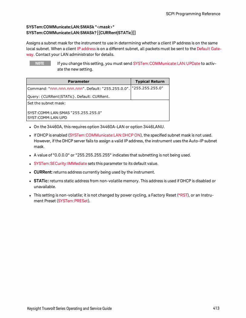
SYSTem:COMMunicate:LAN:SMASk "<mask>"SYSTem:COMMunicate:LAN:SMASk? [CURRent|STATic]]
Assigns a subnet mask for the instrument to use in determining whether a client IP address is on the samelocal subnet. When a client IP address is on a different subnet, all packets must be sent to the Default Gate-way. Contact your LAN administrator for details.
If you change this setting, you must send SYSTem:COMMunicate:LAN:UPDate to activ-ate the new setting.
Parameter Typical Return
Command: "nnn.nnn.nnn.nnn". Default: "255.255.0.0".
Query: CURRent|STATic. Default: CURRent.
"255.255.255.0"
Set the subnet mask:
SYST:COMM:LAN:SMAS "255.255.255.0"SYST:COMM:LAN:UPD
l On the 34460A, this requires option 34460A-LAN or option 3446LANU.
l If DHCP is enabled (SYSTem:COMMunicate:LAN:DHCP ON), the specified subnet mask is not used.However, if the DHCP server fails to assign a valid IP address, the instrument uses the Auto-IP subnetmask.
l A value of "0.0.0.0" or "255.255.255.255" indicates that subnetting is not being used.
l SYSTem:SECurity:IMMediate sets this parameter to its default value.
l CURRent: returns address currently being used by the instrument.
l STATic: returns static address from non-volatile memory. This address is used if DHCP is disabled orunavailable.
l This setting is non-volatile; it is not changed by power cycling, a Factory Reset (*RST), or an Instru-ment Preset (SYSTem:PRESet).
Keysight Truevolt Series Operating and Service Guide 413
SCPI Programming Reference
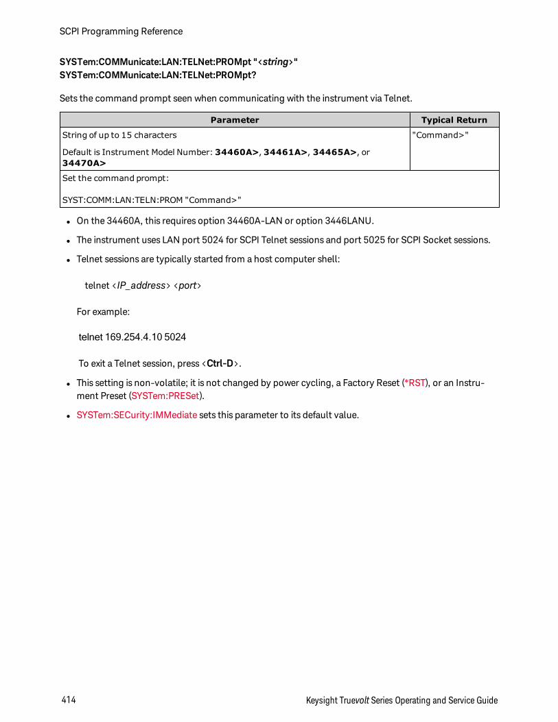
SYSTem:COMMunicate:LAN:TELNet:PROMpt "<string>"SYSTem:COMMunicate:LAN:TELNet:PROMpt?
Sets the command prompt seen when communicating with the instrument via Telnet.
Parameter Typical Return
String of up to 15 characters
Default is Instrument Model Number:34460A>, 34461A>, 34465A>, or34470A>
"Command>"
Set the command prompt:
SYST:COMM:LAN:TELN:PROM "Command>"
l On the 34460A, this requires option 34460A-LAN or option 3446LANU.
l The instrument uses LAN port 5024 for SCPI Telnet sessions and port 5025 for SCPI Socket sessions.
l Telnet sessions are typically started from a host computer shell:
telnet <IP_address> <port>
For example:
telnet 169.254.4.10 5024
To exit a Telnet session, press <Ctrl-D>.
l This setting is non-volatile; it is not changed by power cycling, a Factory Reset (*RST), or an Instru-ment Preset (SYSTem:PRESet).
l SYSTem:SECurity:IMMediate sets this parameter to its default value.
SCPI Programming Reference
414 Keysight Truevolt Series Operating and Service Guide
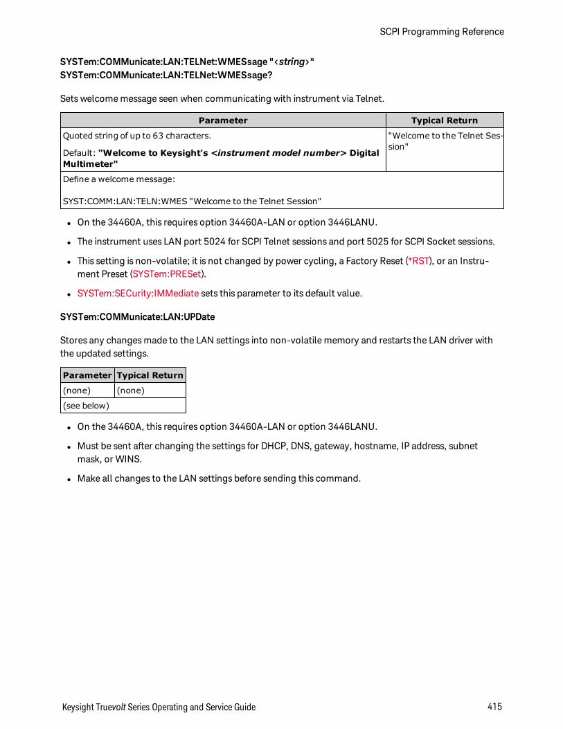
SYSTem:COMMunicate:LAN:TELNet:WMESsage "<string>"SYSTem:COMMunicate:LAN:TELNet:WMESsage?
Sets welcome message seen when communicating with instrument via Telnet.
Parameter Typical Return
Quoted string of up to 63 characters.
Default: "Welcome to Keysight's <instrument model number> DigitalMultimeter"
"Welcome to the Telnet Ses-sion"
Define a welcome message:
SYST:COMM:LAN:TELN:WMES "Welcome to the Telnet Session"
l On the 34460A, this requires option 34460A-LAN or option 3446LANU.
l The instrument uses LAN port 5024 for SCPI Telnet sessions and port 5025 for SCPI Socket sessions.
l This setting is non-volatile; it is not changed by power cycling, a Factory Reset (*RST), or an Instru-ment Preset (SYSTem:PRESet).
l SYSTem:SECurity:IMMediate sets this parameter to its default value.
SYSTem:COMMunicate:LAN:UPDate
Stores any changes made to the LAN settings into non-volatile memory and restarts the LAN driver withthe updated settings.
Parameter Typical Return
(none) (none)
(see below)
l On the 34460A, this requires option 34460A-LAN or option 3446LANU.
l Must be sent after changing the settings for DHCP, DNS, gateway, hostname, IP address, subnetmask, or WINS.
l Make all changes to the LAN settings before sending this command.
Keysight Truevolt Series Operating and Service Guide 415
SCPI Programming Reference
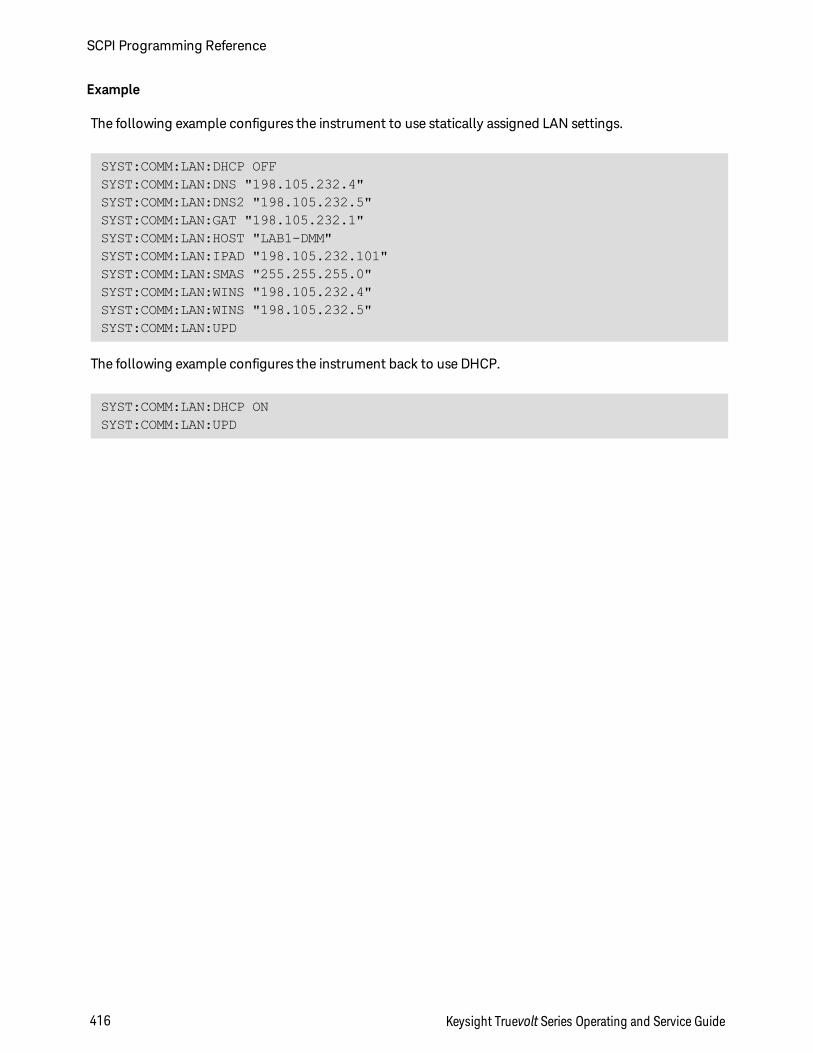
Example
The following example configures the instrument to use statically assigned LAN settings.
SYST:COMM:LAN:DHCP OFFSYST:COMM:LAN:DNS "198.105.232.4"SYST:COMM:LAN:DNS2 "198.105.232.5"SYST:COMM:LAN:GAT "198.105.232.1"SYST:COMM:LAN:HOST "LAB1-DMM"SYST:COMM:LAN:IPAD "198.105.232.101"SYST:COMM:LAN:SMAS "255.255.255.0"SYST:COMM:LAN:WINS "198.105.232.4"SYST:COMM:LAN:WINS "198.105.232.5"SYST:COMM:LAN:UPD
The following example configures the instrument back to use DHCP.
SYST:COMM:LAN:DHCP ONSYST:COMM:LAN:UPD
SCPI Programming Reference
416 Keysight Truevolt Series Operating and Service Guide
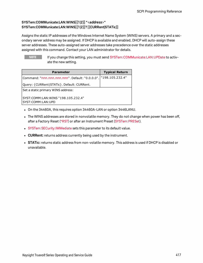
SYSTem:COMMunicate:LAN:WINS[1|2] "<address>"SYSTem:COMMunicate:LAN:WINS[1|2]? [CURRent|STATic]
Assigns the static IP addresses of the Windows Internet Name System (WINS) servers. A primary and a sec-ondary server address may be assigned. If DHCP is available and enabled, DHCP will auto-assign theseserver addresses. These auto-assigned server addresses take precedence over the static addressesassigned with this command. Contact your LAN administrator for details.
If you change this setting, you must send SYSTem:COMMunicate:LAN:UPDate to activ-ate the new setting.
Parameter Typical Return
Command: "nnn.nnn.nnn.nnn". Default: "0.0.0.0".
Query: CURRent|STATic. Default: CURRent.
"198.105.232.4"
Set a static primary WINS address:
SYST:COMM:LAN:WINS "198.105.232.4"SYST:COMM:LAN:UPD
l On the 34460A, this requires option 34460A-LAN or option 3446LANU.
l The WINS addresses are stored in nonvolatile memory. They do not change when power has been off,after a Factory Reset (*RST) or after an Instrument Preset (SYSTem:PRESet).
l SYSTem:SECurity:IMMediate sets this parameter to its default value.
l CURRent: returns address currently being used by the instrument.
l STATic: returns static address from non-volatile memory. This address is used if DHCP is disabled orunavailable.
Keysight Truevolt Series Operating and Service Guide 417
SCPI Programming Reference
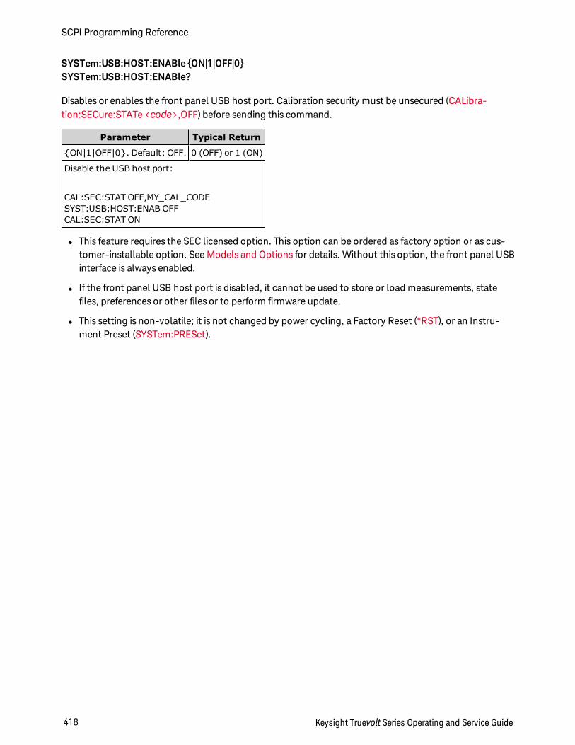
SYSTem:USB:HOST:ENABle ON|1|OFF|0SYSTem:USB:HOST:ENABle?
Disables or enables the front panel USB host port. Calibration security must be unsecured (CALibra-tion:SECure:STATe <code>,OFF) before sending this command.
Parameter Typical Return
ON|1|OFF|0. Default: OFF. 0 (OFF) or 1 (ON)
Disable the USB host port:
CAL:SEC:STAT OFF,MY_CAL_CODESYST:USB:HOST:ENAB OFFCAL:SEC:STAT ON
l This feature requires the SEC licensed option. This option can be ordered as factory option or as cus-tomer-installable option. See Models and Options for details. Without this option, the front panel USBinterface is always enabled.
l If the front panel USB host port is disabled, it cannot be used to store or load measurements, statefiles, preferences or other files or to perform firmware update.
l This setting is non-volatile; it is not changed by power cycling, a Factory Reset (*RST), or an Instru-ment Preset (SYSTem:PRESet).
SCPI Programming Reference
418 Keysight Truevolt Series Operating and Service Guide
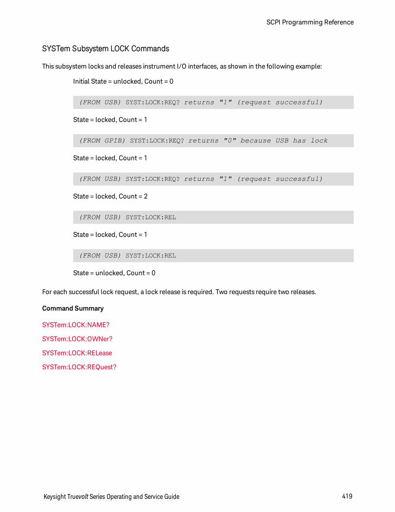
SYSTem Subsystem LOCK Commands
This subsystem locks and releases instrument I/O interfaces, as shown in the following example:
Initial State = unlocked, Count = 0
(FROM USB) SYST:LOCK:REQ? returns "1" (request successful)
State = locked, Count = 1
(FROM GPIB) SYST:LOCK:REQ? returns "0" because USB has lock
State = locked, Count = 1
(FROM USB) SYST:LOCK:REQ? returns "1" (request successful)
State = locked, Count = 2
(FROM USB) SYST:LOCK:REL
State = locked, Count = 1
(FROM USB) SYST:LOCK:REL
State = unlocked, Count = 0
For each successful lock request, a lock release is required. Two requests require two releases.
Command Summary
SYSTem:LOCK:NAME?
SYSTem:LOCK:OWNer?
SYSTem:LOCK:RELease
SYSTem:LOCK:REQuest?
Keysight Truevolt Series Operating and Service Guide 419
SCPI Programming Reference
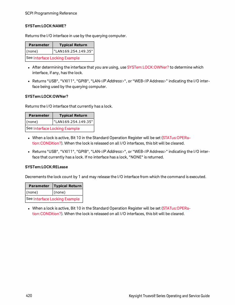
SYSTem:LOCK:NAME?
Returns the I/O interface in use by the querying computer.
Parameter Typical Return
(none) "LAN169.254.149.35"
See Interface Locking Example
l After determining the interface that you are using, use SYSTem:LOCK:OWNer? to determine whichinterface, if any, has the lock.
l Returns "USB", "VXI11", "GPIB", "LAN<IP Address>", or “WEB<IP Address>” indicating the I/O inter-face being used by the querying computer.
SYSTem:LOCK:OWNer?
Returns the I/O interface that currently has a lock.
Parameter Typical Return
(none) "LAN169.254.149.35"
See Interface Locking Example
l When a lock is active, Bit 10 in the Standard Operation Register will be set (STATus:OPERa-tion:CONDition?). When the lock is released on all I/O interfaces, this bit will be cleared.
l Returns "USB", "VXI11", "GPIB", "LAN<IP Address>", or “WEB<IP Address>” indicating the I/O inter-face that currently has a lock. If no interface has a lock, "NONE" is returned.
SYSTem:LOCK:RELease
Decrements the lock count by 1 and may release the I/O interface from which the command is executed.
Parameter Typical Return
(none) (none)
See Interface Locking Example
l When a lock is active, Bit 10 in the Standard Operation Register will be set (STATus:OPERa-tion:CONDition?). When the lock is released on all I/O interfaces, this bit will be cleared.
SCPI Programming Reference
420 Keysight Truevolt Series Operating and Service Guide
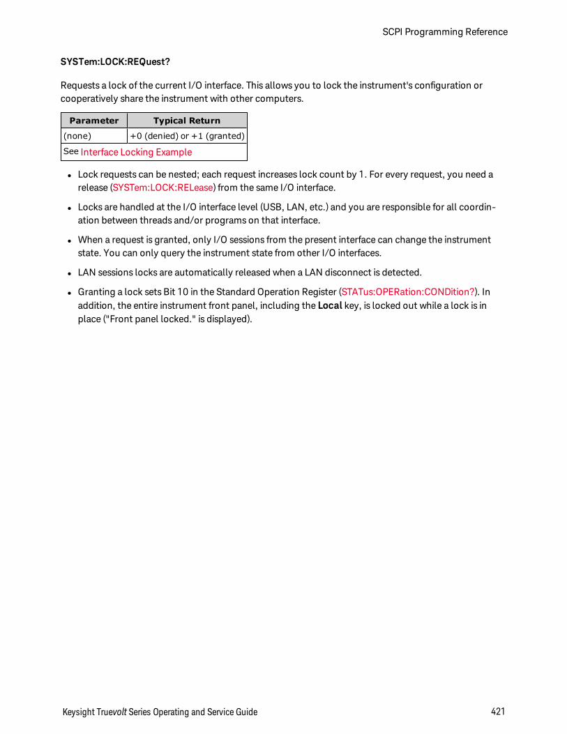
SYSTem:LOCK:REQuest?
Requests a lock of the current I/O interface. This allows you to lock the instrument's configuration orcooperatively share the instrument with other computers.
Parameter Typical Return
(none) +0 (denied) or +1 (granted)
See Interface Locking Example
l Lock requests can be nested; each request increases lock count by 1. For every request, you need arelease (SYSTem:LOCK:RELease) from the same I/O interface.
l Locks are handled at the I/O interface level (USB, LAN, etc.) and you are responsible for all coordin-ation between threads and/or programs on that interface.
l When a request is granted, only I/O sessions from the present interface can change the instrumentstate. You can only query the instrument state from other I/O interfaces.
l LAN sessions locks are automatically released when a LAN disconnect is detected.
l Granting a lock sets Bit 10 in the Standard Operation Register (STATus:OPERation:CONDition?). Inaddition, the entire instrument front panel, including the Local key, is locked out while a lock is inplace ("Front panel locked." is displayed).
Keysight Truevolt Series Operating and Service Guide 421
SCPI Programming Reference
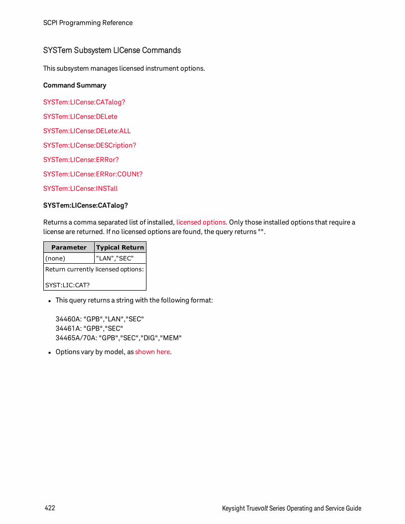
SYSTem Subsystem LICense Commands
This subsystem manages licensed instrument options.
Command Summary
SYSTem:LICense:CATalog?
SYSTem:LICense:DELete
SYSTem:LICense:DELete:ALL
SYSTem:LICense:DESCription?
SYSTem:LICense:ERRor?
SYSTem:LICense:ERRor:COUNt?
SYSTem:LICense:INSTall
SYSTem:LICense:CATalog?
Returns a comma separated list of installed, licensed options. Only those installed options that require alicense are returned. If no licensed options are found, the query returns "".
Parameter Typical Return
(none) "LAN","SEC"
Return currently licensed options:
SYST:LIC:CAT?
l This query returns a string with the following format:
34460A: "GPB","LAN","SEC"34461A: "GPB","SEC"34465A/70A: "GPB","SEC","DIG","MEM"
l Options vary by model, as shown here.
SCPI Programming Reference
422 Keysight Truevolt Series Operating and Service Guide
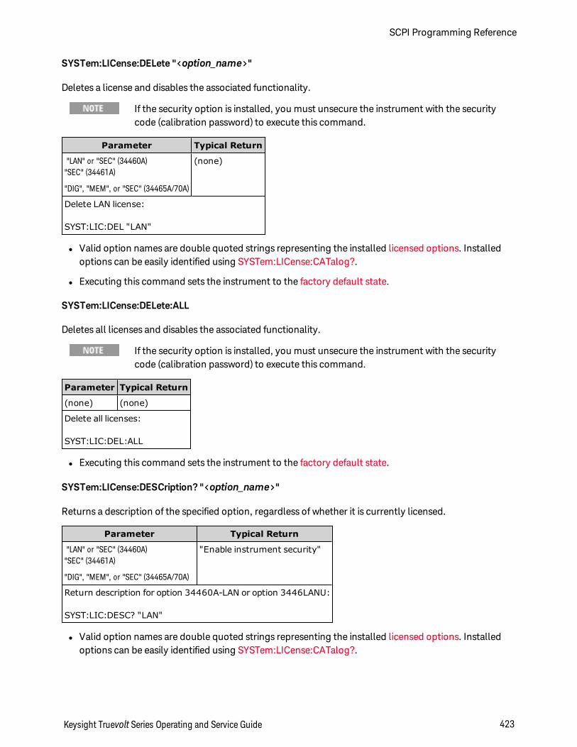
SYSTem:LICense:DELete "<option_name>"
Deletes a license and disables the associated functionality.
If the security option is installed, you must unsecure the instrument with the securitycode (calibration password) to execute this command.
Parameter Typical Return
"LAN" or "SEC" (34460A)"SEC" (34461A)
"DIG", "MEM", or "SEC" (34465A/70A)
(none)
Delete LAN license:
SYST:LIC:DEL "LAN"
l Valid option names are double quoted strings representing the installed licensed options. Installedoptions can be easily identified using SYSTem:LICense:CATalog?.
l Executing this command sets the instrument to the factory default state.
SYSTem:LICense:DELete:ALL
Deletes all licenses and disables the associated functionality.
If the security option is installed, you must unsecure the instrument with the securitycode (calibration password) to execute this command.
Parameter Typical Return
(none) (none)
Delete all licenses:
SYST:LIC:DEL:ALL
l Executing this command sets the instrument to the factory default state.
SYSTem:LICense:DESCription? "<option_name>"
Returns a description of the specified option, regardless of whether it is currently licensed.
Parameter Typical Return
"LAN" or "SEC" (34460A)"SEC" (34461A)
"DIG", "MEM", or "SEC" (34465A/70A)
"Enable instrument security"
Return description for option 34460A-LAN or option 3446LANU:
SYST:LIC:DESC? "LAN"
l Valid option names are double quoted strings representing the installed licensed options. Installedoptions can be easily identified using SYSTem:LICense:CATalog?.
Keysight Truevolt Series Operating and Service Guide 423
SCPI Programming Reference
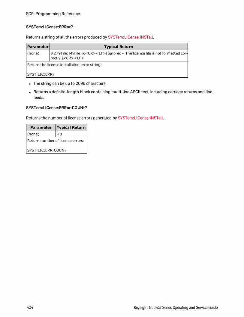
SYSTem:LICense:ERRor?
Returns a string of all the errors produced by SYSTem:LICense:INSTall.
Parameter Typical Return
(none) #279File: MyFile.lic<CR><LF>[Ignored - The license file is not formatted cor-rectly.]<CR><LF>
Return the license installation error string:
SYST:LIC:ERR?
l The string can be up to 2096 characters.
l Returns a definite-length block containing multi-line ASCII text, including carriage returns and linefeeds.
SYSTem:LICense:ERRor:COUNt?
Returns the number of license errors generated by SYSTem:LICense:INSTall.
Parameter Typical Return
(none) +0
Return number of license errors:
SYST:LIC:ERR:COUN?
SCPI Programming Reference
424 Keysight Truevolt Series Operating and Service Guide
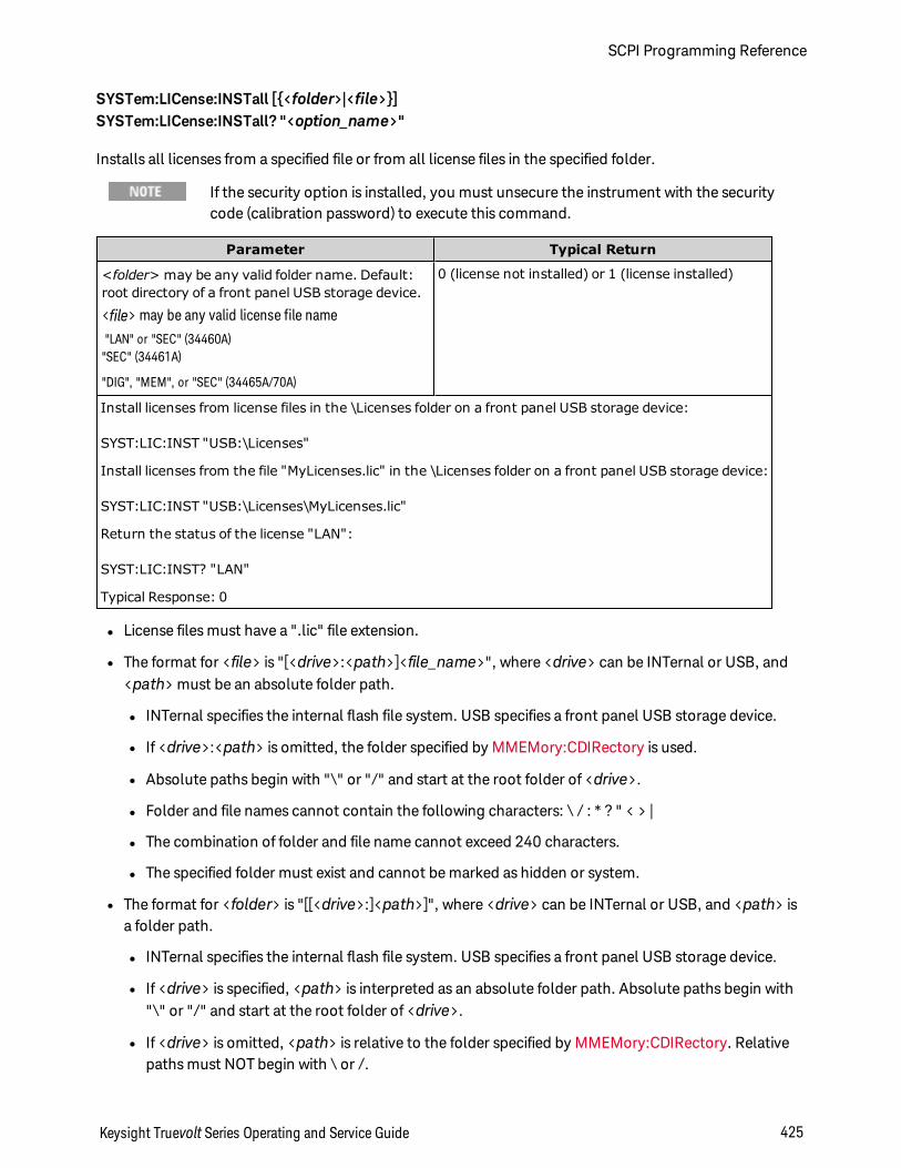
SYSTem:LICense:INSTall [<folder>|<file>]SYSTem:LICense:INSTall? "<option_name>"
Installs all licenses from a specified file or from all license files in the specified folder.
If the security option is installed, you must unsecure the instrument with the securitycode (calibration password) to execute this command.
Parameter Typical Return
<folder> may be any valid folder name. Default:root directory of a front panel USB storage device.
<file> may be any valid license file name"LAN" or "SEC" (34460A)"SEC" (34461A)
"DIG", "MEM", or "SEC" (34465A/70A)
0 (license not installed) or 1 (license installed)
Install licenses from license files in the \Licenses folder on a front panel USB storage device:
SYST:LIC:INST "USB:\Licenses"
Install licenses from the file "MyLicenses.lic" in the \Licenses folder on a front panel USB storage device:
SYST:LIC:INST "USB:\Licenses\MyLicenses.lic"
Return the status of the license "LAN":
SYST:LIC:INST? "LAN"
Typical Response: 0
l License files must have a ".lic" file extension.
l The format for <file> is "[<drive>:<path>]<file_name>", where <drive> can be INTernal or USB, and<path> must be an absolute folder path.
l INTernal specifies the internal flash file system. USB specifies a front panel USB storage device.
l If <drive>:<path> is omitted, the folder specified by MMEMory:CDIRectory is used.
l Absolute paths begin with "\" or "/" and start at the root folder of <drive>.
l Folder and file names cannot contain the following characters: \ / : * ? " < > |
l The combination of folder and file name cannot exceed 240 characters.
l The specified folder must exist and cannot be marked as hidden or system.
l The format for <folder> is "[[<drive>:]<path>]", where <drive> can be INTernal or USB, and <path> isa folder path.
l INTernal specifies the internal flash file system. USB specifies a front panel USB storage device.
l If <drive> is specified, <path> is interpreted as an absolute folder path. Absolute paths begin with"\" or "/" and start at the root folder of <drive>.
l If <drive> is omitted, <path> is relative to the folder specified by MMEMory:CDIRectory. Relativepaths must NOT begin with \ or /.
Keysight Truevolt Series Operating and Service Guide 425
SCPI Programming Reference
l The <folder> parameter cannot exceed 240 characters.
l The specified folder must exist and cannot be marked as hidden or system.
SCPI Programming Reference
426 Keysight Truevolt Series Operating and Service Guide
TRIGger Subsystem
The TRIGger subsystem configures the triggering that controls measurement acquisition.
Recommendation: All triggered measurements should be made using anappropriate fixed manual range. That is, turn autorange off([SENSe:]<function>:RANGe:AUTO OFF) or set a fixed range using the[SENSe:]<function>:RANGe, CONFigure, or MEASure command.
Command Summary
TRIGger:COUNt
TRIGger:DELay
TRIGger:DELay:AUTO
TRIGger:LEVel
TRIGger:SLOPe
TRIGger:SOURce
Keysight Truevolt Series Operating and Service Guide 427
SCPI Programming Reference
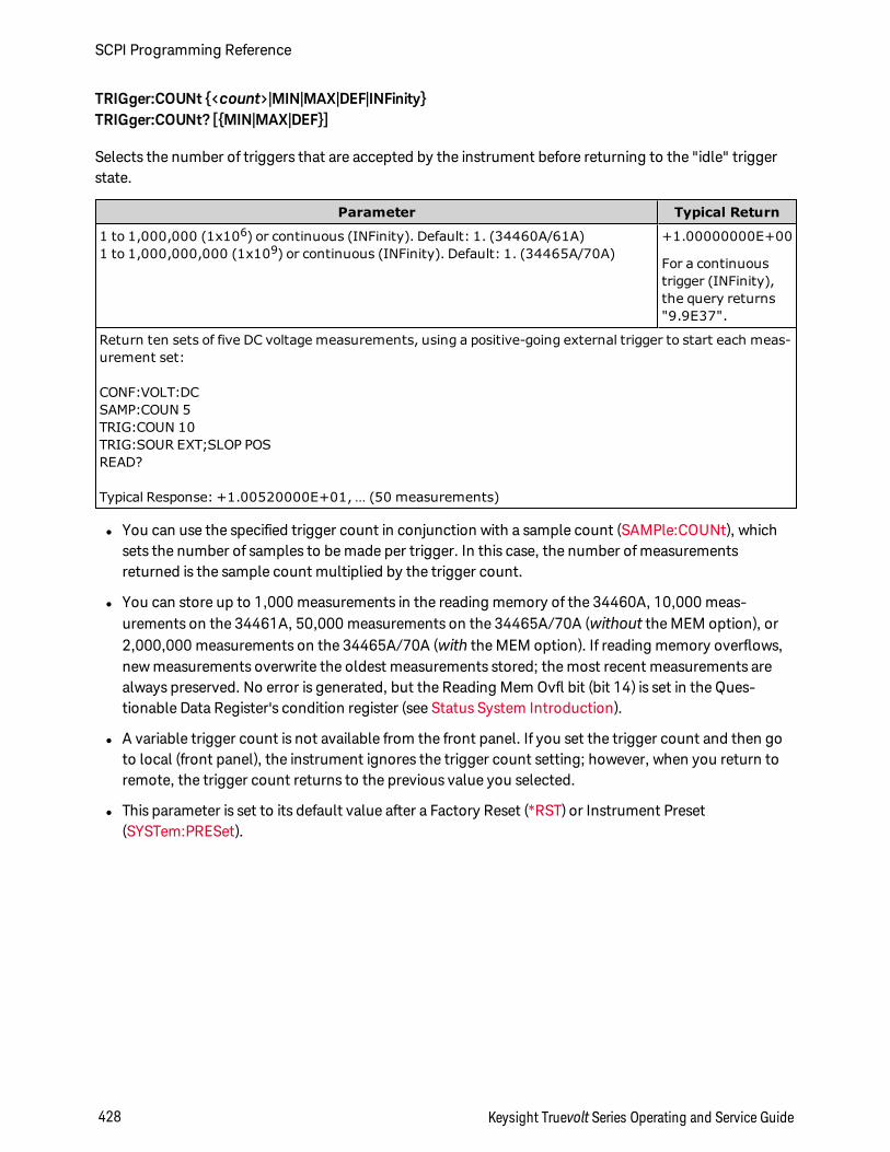
TRIGger:COUNt <count>|MIN|MAX|DEF|INFinityTRIGger:COUNt? [MIN|MAX|DEF]
Selects the number of triggers that are accepted by the instrument before returning to the "idle" triggerstate.
Parameter Typical Return
1 to 1,000,000 (1x10⁶) or continuous (INFinity). Default: 1. (34460A/61A)1 to 1,000,000,000 (1x10⁹) or continuous (INFinity). Default: 1. (34465A/70A)
+1.00000000E+00
For a continuoustrigger (INFinity),the query returns"9.9E37".
Return ten sets of five DC voltage measurements, using a positive-going external trigger to start each meas-urement set:
CONF:VOLT:DCSAMP:COUN 5TRIG:COUN 10TRIG:SOUR EXT;SLOP POSREAD?
Typical Response: +1.00520000E+01, … (50 measurements)
l You can use the specified trigger count in conjunction with a sample count (SAMPle:COUNt), whichsets the number of samples to be made per trigger. In this case, the number of measurementsreturned is the sample count multiplied by the trigger count.
l You can store up to 1,000 measurements in the reading memory of the 34460A, 10,000 meas-urements on the 34461A, 50,000 measurements on the 34465A/70A (without the MEM option), or2,000,000 measurements on the 34465A/70A (with the MEM option). If reading memory overflows,new measurements overwrite the oldest measurements stored; the most recent measurements arealways preserved. No error is generated, but the Reading Mem Ovfl bit (bit 14) is set in the Ques-tionable Data Register's condition register (see Status System Introduction).
l A variable trigger count is not available from the front panel. If you set the trigger count and then goto local (front panel), the instrument ignores the trigger count setting; however, when you return toremote, the trigger count returns to the previous value you selected.
l This parameter is set to its default value after a Factory Reset (*RST) or Instrument Preset(SYSTem:PRESet).
SCPI Programming Reference
428 Keysight Truevolt Series Operating and Service Guide
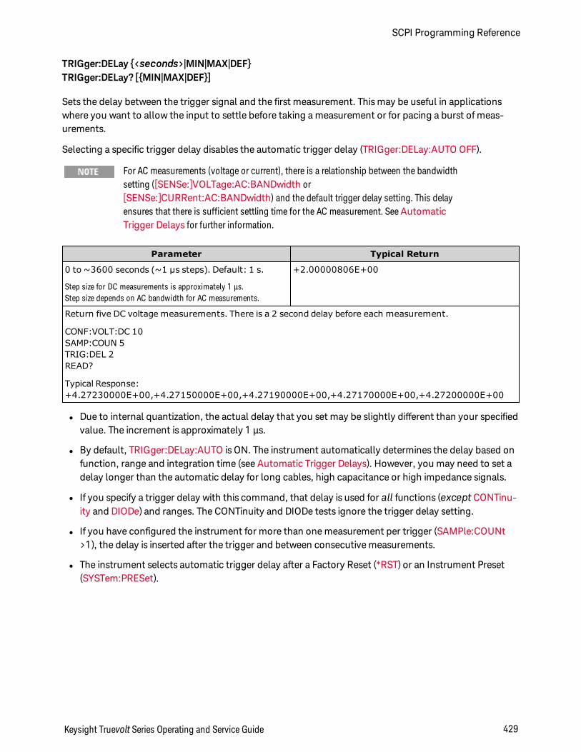
TRIGger:DELay <seconds>|MIN|MAX|DEFTRIGger:DELay? [MIN|MAX|DEF]
Sets the delay between the trigger signal and the first measurement. This may be useful in applicationswhere you want to allow the input to settle before taking a measurement or for pacing a burst of meas-urements.
Selecting a specific trigger delay disables the automatic trigger delay (TRIGger:DELay:AUTO OFF).
For AC measurements (voltage or current), there is a relationship between the bandwidthsetting ([SENSe:]VOLTage:AC:BANDwidth or[SENSe:]CURRent:AC:BANDwidth) and the default trigger delay setting. This delayensures that there is sufficient settling time for the AC measurement. SeeAutomaticTrigger Delays for further information.
Parameter Typical Return
0 to ~3600 seconds (~1 µs steps). Default: 1 s.
Step size for DC measurements is approximately 1 µs.Step size depends on AC bandwidth for AC measurements.
+2.00000806E+00
Return five DC voltage measurements. There is a 2 second delay before each measurement.
CONF:VOLT:DC 10SAMP:COUN 5TRIG:DEL 2READ?
Typical Response:+4.27230000E+00,+4.27150000E+00,+4.27190000E+00,+4.27170000E+00,+4.27200000E+00
l Due to internal quantization, the actual delay that you set may be slightly different than your specifiedvalue. The increment is approximately 1 µs.
l By default, TRIGger:DELay:AUTO is ON. The instrument automatically determines the delay based onfunction, range and integration time (see Automatic Trigger Delays). However, you may need to set adelay longer than the automatic delay for long cables, high capacitance or high impedance signals.
l If you specify a trigger delay with this command, that delay is used for all functions (except CONTinu-ity and DIODe) and ranges. The CONTinuity and DIODe tests ignore the trigger delay setting.
l If you have configured the instrument for more than one measurement per trigger (SAMPle:COUNt>1), the delay is inserted after the trigger and between consecutive measurements.
l The instrument selects automatic trigger delay after a Factory Reset (*RST) or an Instrument Preset(SYSTem:PRESet).
Keysight Truevolt Series Operating and Service Guide 429
SCPI Programming Reference
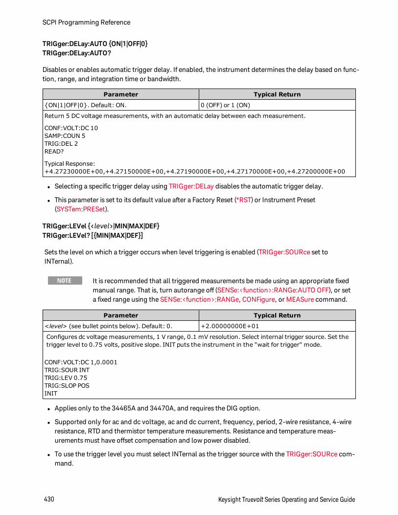
TRIGger:DELay:AUTO ON|1|OFF|0TRIGger:DELay:AUTO?
Disables or enables automatic trigger delay. If enabled, the instrument determines the delay based on func-tion, range, and integration time or bandwidth.
Parameter Typical Return
ON|1|OFF|0. Default: ON. 0 (OFF) or 1 (ON)
Return 5 DC voltage measurements, with an automatic delay between each measurement.
CONF:VOLT:DC 10SAMP:COUN 5TRIG:DEL 2READ?
Typical Response:+4.27230000E+00,+4.27150000E+00,+4.27190000E+00,+4.27170000E+00,+4.27200000E+00
l Selecting a specific trigger delay using TRIGger:DELay disables the automatic trigger delay.
l This parameter is set to its default value after a Factory Reset (*RST) or Instrument Preset(SYSTem:PRESet).
TRIGger:LEVel <level>|MIN|MAX|DEFTRIGger:LEVel? [MIN|MAX|DEF]
Sets the level on which a trigger occurs when level triggering is enabled (TRIGger:SOURce set toINTernal).
It is recommended that all triggered measurements be made using an appropriate fixedmanual range. That is, turn autorange off (SENSe:<function>:RANGe:AUTO OFF), or seta fixed range using the SENSe:<function>:RANGe, CONFigure, or MEASure command.
Parameter Typical Return
<level> (see bullet points below). Default: 0. +2.00000000E+01
Configures dc voltage measurements, 1 V range, 0.1 mV resolution. Select internal trigger source. Set thetrigger level to 0.75 volts, positive slope. INIT puts the instrument in the "wait for trigger" mode.
CONF:VOLT:DC 1,0.0001TRIG:SOUR INTTRIG:LEV 0.75TRIG:SLOP POSINIT
l Applies only to the 34465A and 34470A, and requires the DIG option.
l Supported only for ac and dc voltage, ac and dc current, frequency, period, 2-wire resistance, 4-wireresistance, RTD and thermistor temperature measurements. Resistance and temperature meas-urements must have offset compensation and low power disabled.
l To use the trigger level you must select INTernal as the trigger source with the TRIGger:SOURce com-mand.
SCPI Programming Reference
430 Keysight Truevolt Series Operating and Service Guide
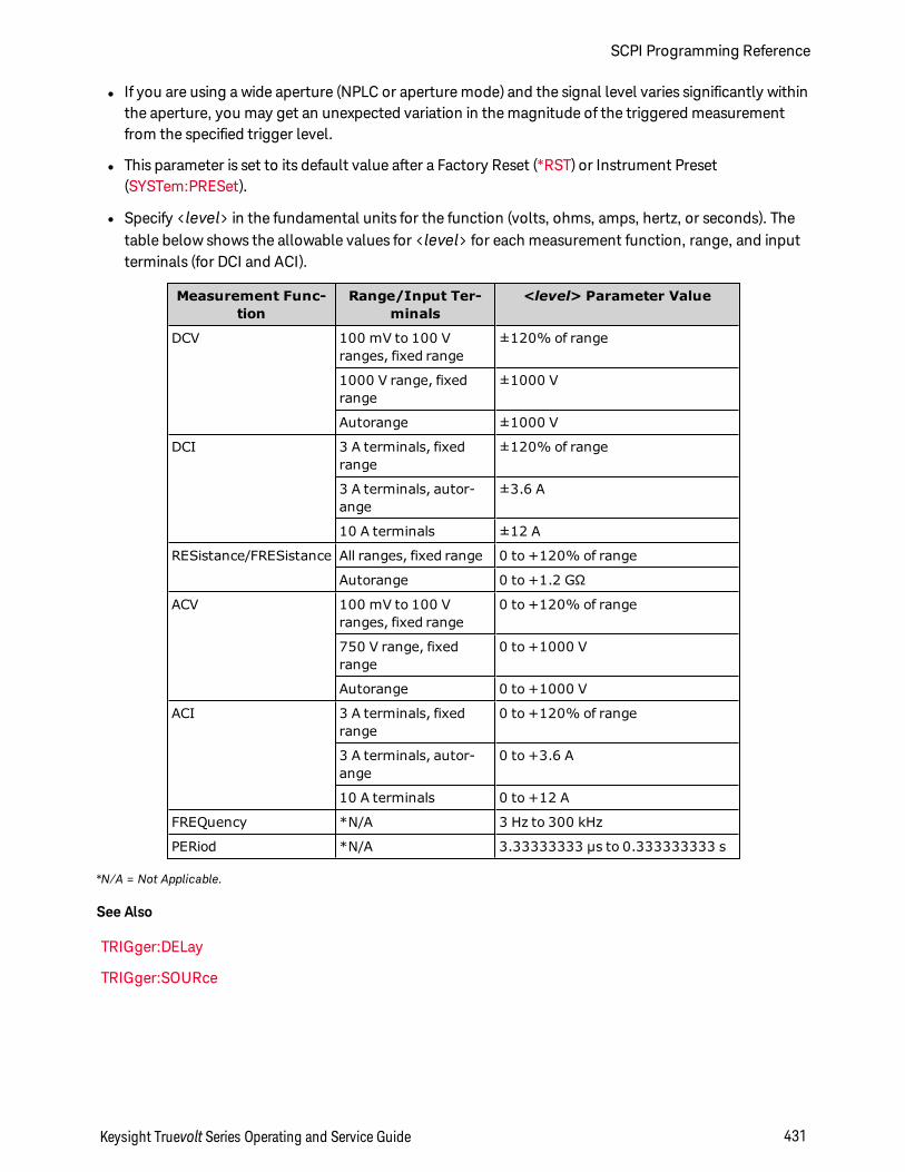
l If you are using a wide aperture (NPLC or aperture mode) and the signal level varies significantly withinthe aperture, you may get an unexpected variation in the magnitude of the triggered measurementfrom the specified trigger level.
l This parameter is set to its default value after a Factory Reset (*RST) or Instrument Preset(SYSTem:PRESet).
l Specify <level> in the fundamental units for the function (volts, ohms, amps, hertz, or seconds). Thetable below shows the allowable values for <level> for each measurement function, range, and inputterminals (for DCI and ACI).
Measurement Func-tion
Range/Input Ter-minals
<level> Parameter Value
DCV 100 mV to 100 Vranges, fixed range
±120% of range
1000 V range, fixedrange
±1000 V
Autorange ±1000 V
DCI 3 A terminals, fixedrange
±120% of range
3 A terminals, autor-ange
±3.6 A
10 A terminals ±12 A
RESistance/FRESistance All ranges, fixed range 0 to +120% of range
Autorange 0 to +1.2 GΩ
ACV 100 mV to 100 Vranges, fixed range
0 to +120% of range
750 V range, fixedrange
0 to +1000 V
Autorange 0 to +1000 V
ACI 3 A terminals, fixedrange
0 to +120% of range
3 A terminals, autor-ange
0 to +3.6 A
10 A terminals 0 to +12 A
FREQuency *N/A 3 Hz to 300 kHz
PERiod *N/A 3.33333333 µs to 0.333333333 s
*N/A = Not Applicable.
See Also
TRIGger:DELay
TRIGger:SOURce
Keysight Truevolt Series Operating and Service Guide 431
SCPI Programming Reference
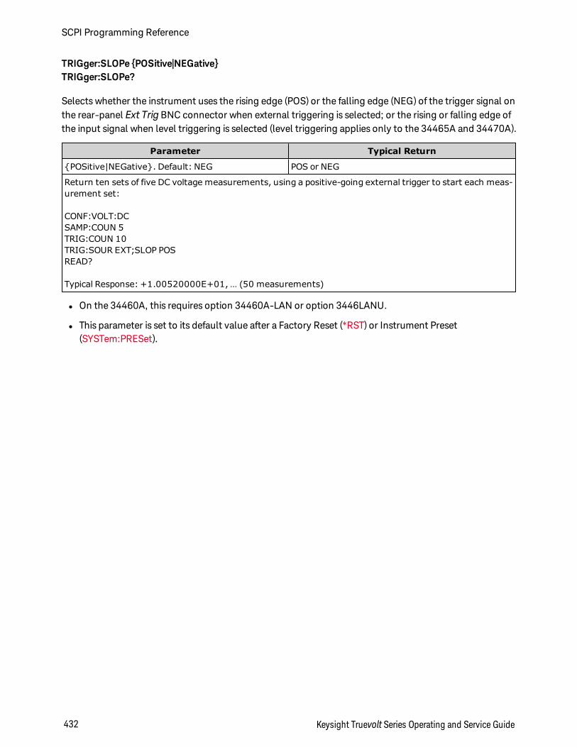
TRIGger:SLOPe POSitive|NEGativeTRIGger:SLOPe?
Selects whether the instrument uses the rising edge (POS) or the falling edge (NEG) of the trigger signal onthe rear-panel Ext Trig BNC connector when external triggering is selected; or the rising or falling edge ofthe input signal when level triggering is selected (level triggering applies only to the 34465A and 34470A).
Parameter Typical Return
POSitive|NEGative. Default: NEG POS or NEG
Return ten sets of five DC voltage measurements, using a positive-going external trigger to start each meas-urement set:
CONF:VOLT:DCSAMP:COUN 5TRIG:COUN 10TRIG:SOUR EXT;SLOP POSREAD?
Typical Response: +1.00520000E+01, … (50 measurements)
l On the 34460A, this requires option 34460A-LAN or option 3446LANU.
l This parameter is set to its default value after a Factory Reset (*RST) or Instrument Preset(SYSTem:PRESet).
SCPI Programming Reference
432 Keysight Truevolt Series Operating and Service Guide
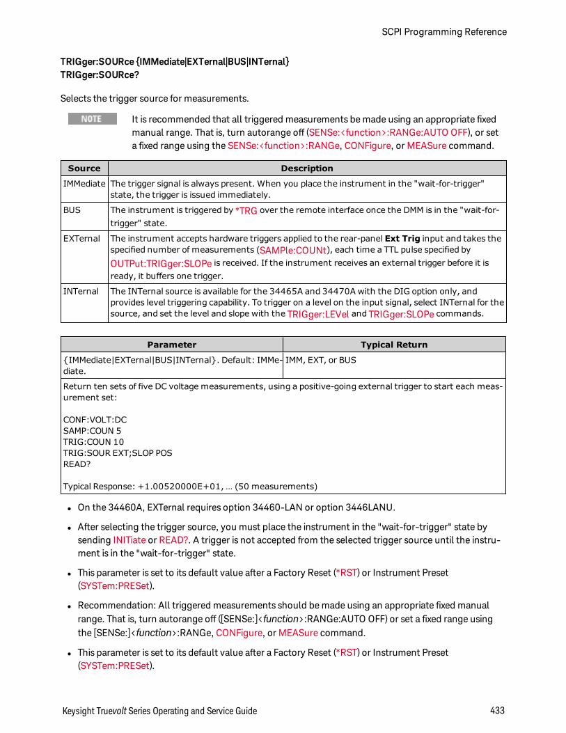
TRIGger:SOURce IMMediate|EXTernal|BUS|INTernalTRIGger:SOURce?
Selects the trigger source for measurements.
It is recommended that all triggered measurements be made using an appropriate fixedmanual range. That is, turn autorange off (SENSe:<function>:RANGe:AUTO OFF), or seta fixed range using the SENSe:<function>:RANGe, CONFigure, or MEASure command.
Source Description
IMMediate The trigger signal is always present. When you place the instrument in the "wait-for-trigger"state, the trigger is issued immediately.
BUS The instrument is triggered by *TRG over the remote interface once the DMM is in the "wait-for-trigger" state.
EXTernal The instrument accepts hardware triggers applied to the rear-panel Ext Trig input and takes thespecified number of measurements (SAMPle:COUNt), each time a TTL pulse specified by
OUTPut:TRIGger:SLOPe is received. If the instrument receives an external trigger before it isready, it buffers one trigger.
INTernal The INTernal source is available for the 34465A and 34470A with the DIG option only, andprovides level triggering capability. To trigger on a level on the input signal, select INTernal for thesource, and set the level and slope with the TRIGger:LEVel and TRIGger:SLOPe commands.
Parameter Typical Return
IMMediate|EXTernal|BUS|INTernal. Default: IMMe-diate.
IMM, EXT, or BUS
Return ten sets of five DC voltage measurements, using a positive-going external trigger to start each meas-urement set:
CONF:VOLT:DCSAMP:COUN 5TRIG:COUN 10TRIG:SOUR EXT;SLOP POSREAD?
Typical Response: +1.00520000E+01, … (50 measurements)
l On the 34460A, EXTernal requires option 34460-LAN or option 3446LANU.
l After selecting the trigger source, you must place the instrument in the "wait-for-trigger" state bysending INITiate or READ?. A trigger is not accepted from the selected trigger source until the instru-ment is in the "wait-for-trigger" state.
l This parameter is set to its default value after a Factory Reset (*RST) or Instrument Preset(SYSTem:PRESet).
l Recommendation: All triggered measurements should be made using an appropriate fixed manualrange. That is, turn autorange off ([SENSe:]<function>:RANGe:AUTO OFF) or set a fixed range usingthe [SENSe:]<function>:RANGe, CONFigure, or MEASure command.
l This parameter is set to its default value after a Factory Reset (*RST) or Instrument Preset(SYSTem:PRESet).
Keysight Truevolt Series Operating and Service Guide 433
SCPI Programming Reference
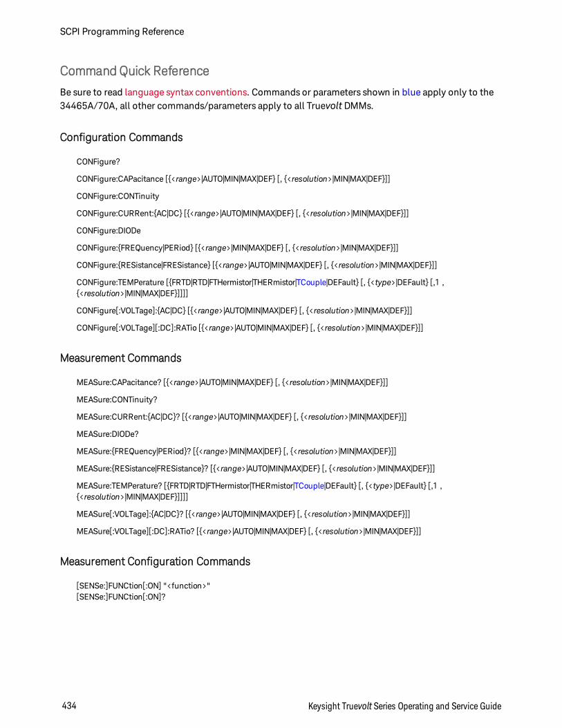
CommandQuick Reference
Be sure to read language syntax conventions. Commands or parameters shown in blue apply only to the34465A/70A, all other commands/parameters apply to all Truevolt DMMs.
Configuration Commands
CONFigure?
CONFigure:CAPacitance [<range>|AUTO|MIN|MAX|DEF [, <resolution>|MIN|MAX|DEF]]
CONFigure:CONTinuity
CONFigure:CURRent:AC|DC [<range>|AUTO|MIN|MAX|DEF [, <resolution>|MIN|MAX|DEF]]
CONFigure:DIODe
CONFigure:FREQuency|PERiod [<range>|MIN|MAX|DEF [, <resolution>|MIN|MAX|DEF]]
CONFigure:RESistance|FRESistance [<range>|AUTO|MIN|MAX|DEF [, <resolution>|MIN|MAX|DEF]]
CONFigure:TEMPerature [FRTD|RTD|FTHermistor|THERmistor|TCouple|DEFault [, <type>|DEFault [,1 ,<resolution>|MIN|MAX|DEF]]]]
CONFigure[:VOLTage]:AC|DC [<range>|AUTO|MIN|MAX|DEF [, <resolution>|MIN|MAX|DEF]]
CONFigure[:VOLTage][:DC]:RATio [<range>|AUTO|MIN|MAX|DEF [, <resolution>|MIN|MAX|DEF]]
Measurement Commands
MEASure:CAPacitance? [<range>|AUTO|MIN|MAX|DEF [, <resolution>|MIN|MAX|DEF]]
MEASure:CONTinuity?
MEASure:CURRent:AC|DC? [<range>|AUTO|MIN|MAX|DEF [, <resolution>|MIN|MAX|DEF]]
MEASure:DIODe?
MEASure:FREQuency|PERiod? [<range>|MIN|MAX|DEF [, <resolution>|MIN|MAX|DEF]]
MEASure:RESistance|FRESistance? [<range>|AUTO|MIN|MAX|DEF [, <resolution>|MIN|MAX|DEF]]
MEASure:TEMPerature? [FRTD|RTD|FTHermistor|THERmistor|TCouple|DEFault [, <type>|DEFault [,1 ,<resolution>|MIN|MAX|DEF]]]]
MEASure[:VOLTage]:AC|DC? [<range>|AUTO|MIN|MAX|DEF [, <resolution>|MIN|MAX|DEF]]
MEASure[:VOLTage][:DC]:RATio? [<range>|AUTO|MIN|MAX|DEF [, <resolution>|MIN|MAX|DEF]]
Measurement Configuration Commands
[SENSe:]FUNCtion[:ON] "<function>"[SENSe:]FUNCtion[:ON]?
SCPI Programming Reference
434 Keysight Truevolt Series Operating and Service Guide
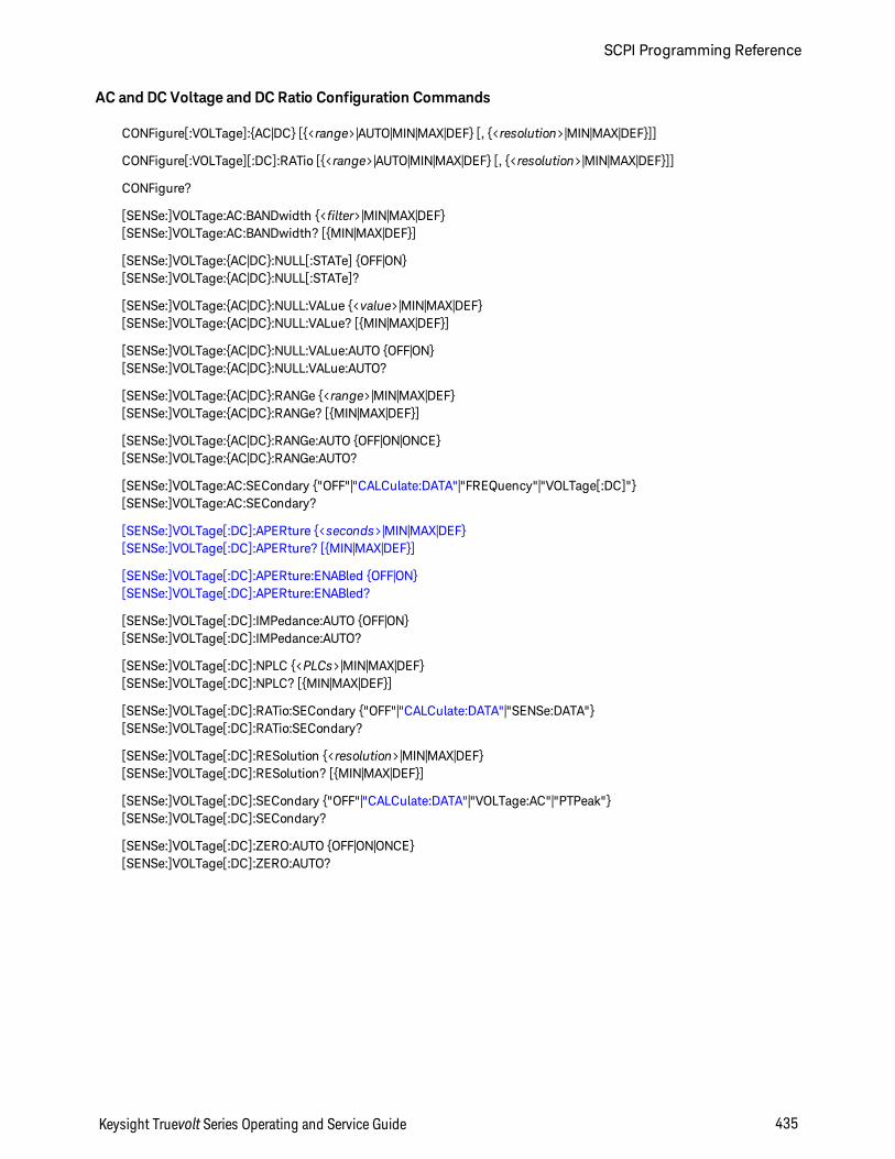
AC and DC Voltage and DC Ratio Configuration Commands
CONFigure[:VOLTage]:AC|DC [<range>|AUTO|MIN|MAX|DEF [, <resolution>|MIN|MAX|DEF]]
CONFigure[:VOLTage][:DC]:RATio [<range>|AUTO|MIN|MAX|DEF [, <resolution>|MIN|MAX|DEF]]
CONFigure?
[SENSe:]VOLTage:AC:BANDwidth <filter>|MIN|MAX|DEF[SENSe:]VOLTage:AC:BANDwidth? [MIN|MAX|DEF]
[SENSe:]VOLTage:AC|DC:NULL[:STATe] OFF|ON[SENSe:]VOLTage:AC|DC:NULL[:STATe]?
[SENSe:]VOLTage:AC|DC:NULL:VALue <value>|MIN|MAX|DEF[SENSe:]VOLTage:AC|DC:NULL:VALue? [MIN|MAX|DEF]
[SENSe:]VOLTage:AC|DC:NULL:VALue:AUTO OFF|ON[SENSe:]VOLTage:AC|DC:NULL:VALue:AUTO?
[SENSe:]VOLTage:AC|DC:RANGe <range>|MIN|MAX|DEF[SENSe:]VOLTage:AC|DC:RANGe? [MIN|MAX|DEF]
[SENSe:]VOLTage:AC|DC:RANGe:AUTO OFF|ON|ONCE[SENSe:]VOLTage:AC|DC:RANGe:AUTO?
[SENSe:]VOLTage:AC:SECondary "OFF"|"CALCulate:DATA"|"FREQuency"|"VOLTage[:DC]"[SENSe:]VOLTage:AC:SECondary?
[SENSe:]VOLTage[:DC]:APERture <seconds>|MIN|MAX|DEF[SENSe:]VOLTage[:DC]:APERture? [MIN|MAX|DEF]
[SENSe:]VOLTage[:DC]:APERture:ENABled OFF|ON[SENSe:]VOLTage[:DC]:APERture:ENABled?
[SENSe:]VOLTage[:DC]:IMPedance:AUTO OFF|ON[SENSe:]VOLTage[:DC]:IMPedance:AUTO?
[SENSe:]VOLTage[:DC]:NPLC <PLCs>|MIN|MAX|DEF[SENSe:]VOLTage[:DC]:NPLC? [MIN|MAX|DEF]
[SENSe:]VOLTage[:DC]:RATio:SECondary "OFF"|"CALCulate:DATA"|"SENSe:DATA"[SENSe:]VOLTage[:DC]:RATio:SECondary?
[SENSe:]VOLTage[:DC]:RESolution <resolution>|MIN|MAX|DEF[SENSe:]VOLTage[:DC]:RESolution? [MIN|MAX|DEF]
[SENSe:]VOLTage[:DC]:SECondary "OFF"|"CALCulate:DATA"|"VOLTage:AC"|"PTPeak"[SENSe:]VOLTage[:DC]:SECondary?
[SENSe:]VOLTage[:DC]:ZERO:AUTO OFF|ON|ONCE[SENSe:]VOLTage[:DC]:ZERO:AUTO?
Keysight Truevolt Series Operating and Service Guide 435
SCPI Programming Reference
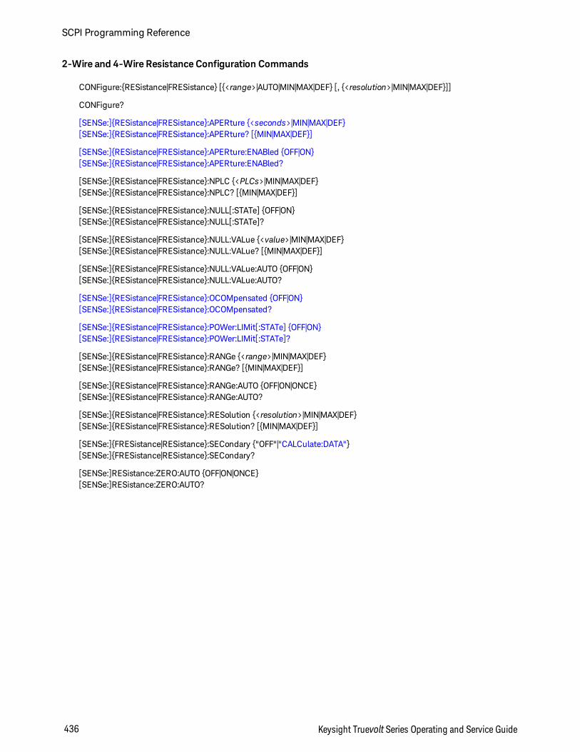
2-Wire and 4-Wire Resistance Configuration Commands
CONFigure:RESistance|FRESistance [<range>|AUTO|MIN|MAX|DEF [, <resolution>|MIN|MAX|DEF]]
CONFigure?
[SENSe:]RESistance|FRESistance:APERture <seconds>|MIN|MAX|DEF[SENSe:]RESistance|FRESistance:APERture? [MIN|MAX|DEF]
[SENSe:]RESistance|FRESistance:APERture:ENABled OFF|ON[SENSe:]RESistance|FRESistance:APERture:ENABled?
[SENSe:]RESistance|FRESistance:NPLC <PLCs>|MIN|MAX|DEF[SENSe:]RESistance|FRESistance:NPLC? [MIN|MAX|DEF]
[SENSe:]RESistance|FRESistance:NULL[:STATe] OFF|ON[SENSe:]RESistance|FRESistance:NULL[:STATe]?
[SENSe:]RESistance|FRESistance:NULL:VALue <value>|MIN|MAX|DEF[SENSe:]RESistance|FRESistance:NULL:VALue? [MIN|MAX|DEF]
[SENSe:]RESistance|FRESistance:NULL:VALue:AUTO OFF|ON[SENSe:]RESistance|FRESistance:NULL:VALue:AUTO?
[SENSe:]RESistance|FRESistance:OCOMpensated OFF|ON[SENSe:]RESistance|FRESistance:OCOMpensated?
[SENSe:]RESistance|FRESistance:POWer:LIMit[:STATe] OFF|ON[SENSe:]RESistance|FRESistance:POWer:LIMit[:STATe]?
[SENSe:]RESistance|FRESistance:RANGe <range>|MIN|MAX|DEF[SENSe:]RESistance|FRESistance:RANGe? [MIN|MAX|DEF]
[SENSe:]RESistance|FRESistance:RANGe:AUTO OFF|ON|ONCE[SENSe:]RESistance|FRESistance:RANGe:AUTO?
[SENSe:]RESistance|FRESistance:RESolution <resolution>|MIN|MAX|DEF[SENSe:]RESistance|FRESistance:RESolution? [MIN|MAX|DEF]
[SENSe:]FRESistance|RESistance:SECondary "OFF"|"CALCulate:DATA"[SENSe:]FRESistance|RESistance:SECondary?
[SENSe:]RESistance:ZERO:AUTO OFF|ON|ONCE[SENSe:]RESistance:ZERO:AUTO?
SCPI Programming Reference
436 Keysight Truevolt Series Operating and Service Guide
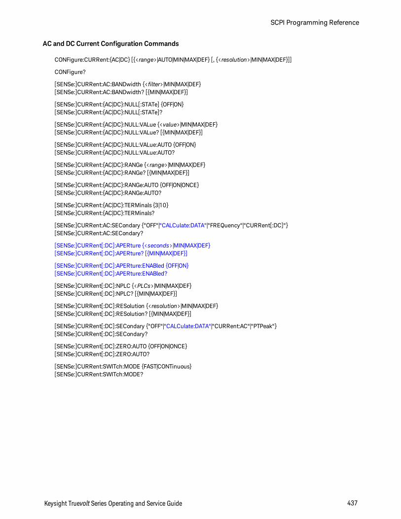
AC and DC Current Configuration Commands
CONFigure:CURRent:AC|DC [<range>|AUTO|MIN|MAX|DEF [, <resolution>|MIN|MAX|DEF]]
CONFigure?
[SENSe:]CURRent:AC:BANDwidth <filter>|MIN|MAX|DEF[SENSe:]CURRent:AC:BANDwidth? [MIN|MAX|DEF]
[SENSe:]CURRent:AC|DC:NULL[:STATe] OFF|ON[SENSe:]CURRent:AC|DC:NULL[:STATe]?
[SENSe:]CURRent:AC|DC:NULL:VALue <value>|MIN|MAX|DEF[SENSe:]CURRent:AC|DC:NULL:VALue? [MIN|MAX|DEF]
[SENSe:]CURRent:AC|DC:NULL:VALue:AUTO OFF|ON[SENSe:]CURRent:AC|DC:NULL:VALue:AUTO?
[SENSe:]CURRent:AC|DC:RANGe <range>|MIN|MAX|DEF[SENSe:]CURRent:AC|DC:RANGe? [MIN|MAX|DEF]
[SENSe:]CURRent:AC|DC:RANGe:AUTO OFF|ON|ONCE[SENSe:]CURRent:AC|DC:RANGe:AUTO?
[SENSe:]CURRent:AC|DC:TERMinals 3|10[SENSe:]CURRent:AC|DC:TERMinals?
[SENSe:]CURRent:AC:SECondary "OFF"|"CALCulate:DATA"|"FREQuency"|"CURRent[:DC]"[SENSe:]CURRent:AC:SECondary?
[SENSe:]CURRent[:DC]:APERture <seconds>|MIN|MAX|DEF[SENSe:]CURRent[:DC]:APERture? [MIN|MAX|DEF]
[SENSe:]CURRent[:DC]:APERture:ENABled OFF|ON[SENSe:]CURRent[:DC]:APERture:ENABled?
[SENSe:]CURRent[:DC]:NPLC <PLCs>|MIN|MAX|DEF[SENSe:]CURRent[:DC]:NPLC? [MIN|MAX|DEF]
[SENSe:]CURRent[:DC]:RESolution <resolution>|MIN|MAX|DEF[SENSe:]CURRent[:DC]:RESolution? [MIN|MAX|DEF]
[SENSe:]CURRent[:DC]:SECondary "OFF"|"CALCulate:DATA"|"CURRent:AC"|"PTPeak"[SENSe:]CURRent[:DC]:SECondary?
[SENSe:]CURRent[:DC]:ZERO:AUTO OFF|ON|ONCE[SENSe:]CURRent[:DC]:ZERO:AUTO?
[SENSe:]CURRent:SWITch:MODE FAST|CONTinuous[SENSe:]CURRent:SWITch:MODE?
Keysight Truevolt Series Operating and Service Guide 437
SCPI Programming Reference
Capacitance Configuration Commands
CONFigure:CAPacitance [<range>|AUTO|MIN|MAX|DEF [, <resolution>|MIN|MAX|DEF]]
CONFigure?
[SENSe:]CAPacitance:NULL[:STATe] OFF|ON[SENSe:]CAPacitance:NULL[:STATe]?
[SENSe:]CAPacitance:NULL:VALue <value>|MIN|MAX|DEF[SENSe:]CAPacitance:NULL:VALue? [MIN|MAX|DEF]
[SENSe:]CAPacitance:NULL:VALue:AUTO OFF|ON[SENSe:]CAPacitance:NULL:VALue:AUTO?
[SENSe:]CAPacitance:RANGe <range>|MIN|MAX|DEF[SENSe:]CAPacitance:RANGe? [MIN|MAX|DEF]
[SENSe:]CAPacitance:RANGe:AUTO OFF|ON|ONCE[SENSe:]CAPacitance:RANGe:AUTO?
[SENSe:]CAPacitance:SECondary"OFF"|"CALCulate:DATA"[SENSe:]CAPacitance:SECondary?
Temperature Configuration Commands
CONFigure:TEMPerature [FRTD|RTD|FTHermistor|THERmistor|TCouple|DEFault [, <type>|DEFault [,1 ,<resolution>|MIN|MAX|DEF]]]]CONFigure?
[SENSe:]TEMPerature:APERture <seconds>|MIN|MAX|DEF[SENSe:]TEMPerature:APERture? [MIN|MAX|DEF]
[SENSe:]TEMPerature:APERture:ENABled OFF|ON[SENSe:]TEMPerature:APERture:ENABled?
[SENSe:]TEMPerature:NPLC <PLCs>|MIN|MAX|DEF[SENSe:]TEMPerature:NPLC? [MIN|MAX|DEF]
[SENSe:]TEMPerature:NULL[:STATe] OFF|ON[SENSe:]TEMPerature:NULL[:STATe]?
[SENSe:]TEMPerature:NULL:VALue <value>|MIN|MAX|DEF[SENSe:]TEMPerature:NULL:VALue? [MIN|MAX|DEF]
[SENSe:]TEMPerature:NULL:VALue:AUTO OFF|ON[SENSe:]TEMPerature:NULL:VALue:AUTO?
[SENSe:]TEMPerature:SECondary "OFF"|"CALCulate:DATA"|"SENSe:DATA"[SENSe:]TEMPerature:SECondary?
[SENSe:]TEMPerature:TRANsducer:FRTD|RTD:OCOMpensated OFF|ON[SENSe:]TEMPerature:TRANsducer:FRTD|RTD:OCOMpensated?
[SENSe:]TEMPerature:TRANsducer:FRTD|RTD:POWer:LIMit[:STATe] OFF|ON[SENSe:]TEMPerature:TRANsducer:FRTD|RTD:POWer:LIMit[:STATe]?
[SENSe:]TEMPerature:TRANsducer:FRTD|RTD:RESistance[:REFerence] <reference>|MIN|MAX|DEF[SENSe:]TEMPerature:TRANsducer:FRTD|RTD:RESistance[:REFerence]? [MIN|MAX|DEF]
[SENSe:]TEMPerature:TRANsducer:FTHermistor|THERmistor:POWer:LIMit[:STATe] OFF|ON[SENSe:]TEMPerature:TRANsducer:FTHermistor|THERmistor:POWer:LIMit[:STATe]?
[SENSe:]TEMPerature:TRANsducer:TCouple:CHECk OFF|ON[SENSe:]TEMPerature:TRANsducer:TCouple:CHECk?
SCPI Programming Reference
438 Keysight Truevolt Series Operating and Service Guide
[SENSe:]TEMPerature:TRANsducer:TCouple:RJUNction <temperature>|MIN|MAX|DEF[SENSe:]TEMPerature:TRANsducer:TCouple:RJUNction? [MIN|MAX|DEF]
[SENSe:]TEMPerature:TRANsducer:TCouple:RJUNction:OFFSet:ADJust <temperature>|MIN|MAX|DEF[SENSe:]TEMPerature:TRANsducer:TCouple:RJUNction:OFFSet:ADJust? [MIN|MAX|DEF]
[SENSe:]TEMPerature:TRANsducer:TCouple:RJUNction:TYPE INTernal|FIXed[SENSe:]TEMPerature:TRANsducer:TCouple:RJUNction:TYPE?
[SENSe:]TEMPerature:TRANsducer:TCouple:TYPE E|J|K|N|R|T[SENSe:]TEMPerature:TRANsducer:TCouple:TYPE?
[SENSe:]TEMPerature:TRANsducer:TYPE FRTD|RTD|FTHermistor|THERmistor|TCouple[SENSe:]TEMPerature:TRANsducer:TYPE?
[SENSe:]TEMPerature:ZERO:AUTO OFF|ON|ONCE[SENSe:]TEMPerature:ZERO:AUTO?
UNIT:TEMPerature C|F|KUNIT:TEMPerature?
Frequency/Period Configuration Commands
CONFigure:FREQuency|PERiod [<range>|MIN|MAX|DEF [, <resolution>|MIN|MAX|DEF]]CONFigure?
[SENSe:]FREQuency|PERiod:APERture <seconds>|MIN|MAX|DEF[SENSe:]FREQuency|PERiod:APERture? [MIN|MAX|DEF]
[SENSe:]FREQuency|PERiod:NULL[:STATe] OFF|ON[SENSe:]FREQuency|PERiod:NULL[:STATe]?
[SENSe:]FREQuency|PERiod:NULL:VALue <value>|MIN|MAX|DEF[SENSe:]FREQuency|PERiod:NULL:VALue? [MIN|MAX|DEF]
[SENSe:]FREQuency|PERiod:NULL:VALue:AUTO OFF|ON[SENSe:]FREQuency|PERiod:NULL:VALue:AUTO?
[SENSe:]FREQuency|PERiod:RANGe:LOWer <freq>|MIN|MAX|DEF[SENSe:]FREQuency|PERiod:RANGe:LOWer?
[SENSe:]FREQuency|PERiod:TIMeout:AUTO OFF|ON
[SENSe:]FREQuency|PERiod:VOLTage:RANGe <range>|MIN|MAX|DEF[SENSe:]FREQuency|PERiod:VOLTage:RANGe? [MIN|MAX|DEF]
[SENSe:]FREQuency|PERiod:VOLTage:RANGe:AUTO OFF|ON|ONCE[SENSe:]FREQuency|PERiod:VOLTage:RANGe:AUTO?
[SENSe:]FREQuency:SECondary "OFF"|"CALCulate:DATA"|"PERiod"|"VOLTage:AC"[SENSe:]FREQuency:SECondary?
[SENSe:]PERiod:SECondary "OFF"|"CALCulate:DATA"|"FREQuency"|"VOLTage:AC"[SENSe:]PERiod:SECondary?
Continuity and Diode Configuration Commands
CONFigure:CONTinuity
CONFigure:DIODe
Keysight Truevolt Series Operating and Service Guide 439
SCPI Programming Reference
Secondary Measurement Commands
[SENSe:]CAPacitance:SECondary "OFF"|"CALCulate:DATA"[SENSe:]CAPacitance:SECondary?
[SENSe:]CURRent:AC:SECondary "OFF"|"CALCulate:DATA"|"FREQuency"|"CURRent[:DC]"[SENSe:]CURRent:AC:SECondary?
[SENSe:]CURRent[:DC]:SECondary "OFF"|"CALCulate:DATA"|"CURRent:AC"|"PTPeak"[SENSe:]CURRent[:DC]:SECondary?
[SENSe:]DATA2?
[SENSe:]DATA2:CLEar[:IMMediate]
[SENSe:]FRESistance|RESistance:SECondary "OFF"|"CALCulate:DATA"[SENSe:]FRESistance|RESistance:SECondary?
[SENSe:]FREQuency:SECondary "OFF"|"CALCulate:DATA"|"PERiod"|"VOLTage:AC"[SENSe:]PERiod:SECondary "OFF"|"CALCulate:DATA"|"FREQuency"|"VOLTage:AC"
[SENSe:]TEMPerature:SECondary "OFF"|"CALCulate:DATA"|"SENSe:DATA"[SENSe:]TEMPerature:SECondary?
[SENSe:]VOLTage:AC:SECondary "OFF"|"CALCulate:DATA"|"FREQuency"|"VOLTage[:DC]"[SENSe:]VOLTage:AC:SECondary?
[SENSe:]VOLTage[:DC]:RATio:SECondary "OFF"|"CALCulate:DATA"|"SENSe:DATA"[SENSe:]VOLTage[:DC]:RATio:SECondary?
[SENSe:]VOLTage[:DC]:SECondary "OFF"|"CALCulate:DATA"|"VOLTage:AC"|"PTPeak"[SENSe:]VOLTage[:DC]:SECondary?
Miscellaneous Configuration Commands
ROUTe:TERMinals?
SCPI Programming Reference
440 Keysight Truevolt Series Operating and Service Guide
Sample Commands
SAMPle:COUNt <count>|MIN|MAX|DEFSAMPle:COUNt? [MIN|MAX|DEF]
SAMPle:COUNt:PRETrigger <count>|MIN|MAX|DEFSAMPle:COUNt:PRETrigger? [MIN|MAX|DEF]
SAMPle:SOURce IMMediate|TIMerSAMPle:SOURce?
SAMPle:TIMer <interval>|MIN|MAX|DEFSAMPle:TIMer? [MIN|MAX|DEF]
Triggering Commands
ABORt
INITiate[:IMMediate]
OUTPut:TRIGger:SLOPe POSitive|NEGativeOUTPut:TRIGger:SLOPe?
READ?
SAMPle:COUNt <count>|MIN|MAX|DEFSAMPle:COUNt? [MIN|MAX|DEF]
SAMPle:COUNt:PRETrigger <count>|MIN|MAX|DEFSAMPle:COUNt:PRETrigger? [MIN|MAX|DEF]
*TRG
TRIGger:COUNt <count>|MIN|MAX|DEF|INFinityTRIGger:COUNt? [MIN|MAX|DEF]
TRIGger:DELay <seconds>|MIN|MAX|DEFTRIGger:DELay? [MIN|MAX|DEF]
TRIGger:DELay:AUTO OFF|ONTRIGger:DELay:AUTO?
TRIGger:LEVel <level>|MIN|MAX|DEFTRIGger:LEVel? [MIN|MAX|DEF]
TRIGger:SLOPe POSitive|NEGativeTRIGger:SLOPe?
TRIGger:SOURce IMMediate|EXTernal|BUS|INTernalTRIGger:SOURce?
Keysight Truevolt Series Operating and Service Guide 441
SCPI Programming Reference
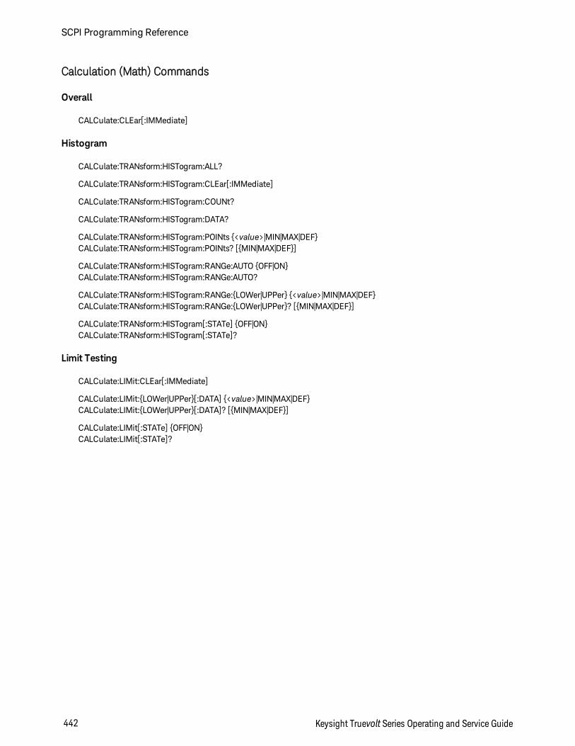
Calculation (Math) Commands
Overall
CALCulate:CLEar[:IMMediate]
Histogram
CALCulate:TRANsform:HISTogram:ALL?
CALCulate:TRANsform:HISTogram:CLEar[:IMMediate]
CALCulate:TRANsform:HISTogram:COUNt?
CALCulate:TRANsform:HISTogram:DATA?
CALCulate:TRANsform:HISTogram:POINts <value>|MIN|MAX|DEFCALCulate:TRANsform:HISTogram:POINts? [MIN|MAX|DEF]
CALCulate:TRANsform:HISTogram:RANGe:AUTO OFF|ONCALCulate:TRANsform:HISTogram:RANGe:AUTO?
CALCulate:TRANsform:HISTogram:RANGe:LOWer|UPPer <value>|MIN|MAX|DEFCALCulate:TRANsform:HISTogram:RANGe:LOWer|UPPer? [MIN|MAX|DEF]
CALCulate:TRANsform:HISTogram[:STATe] OFF|ONCALCulate:TRANsform:HISTogram[:STATe]?
Limit Testing
CALCulate:LIMit:CLEar[:IMMediate]
CALCulate:LIMit:LOWer|UPPer[:DATA] <value>|MIN|MAX|DEFCALCulate:LIMit:LOWer|UPPer[:DATA]? [MIN|MAX|DEF]
CALCulate:LIMit[:STATe] OFF|ONCALCulate:LIMit[:STATe]?
SCPI Programming Reference
442 Keysight Truevolt Series Operating and Service Guide
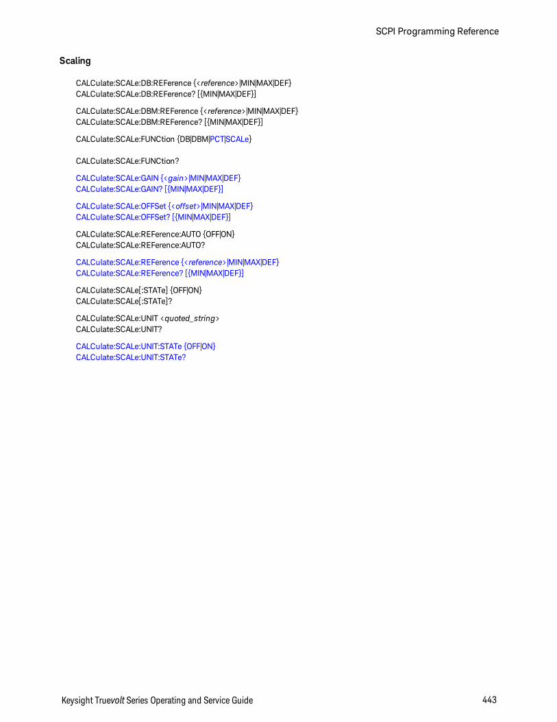
Scaling
CALCulate:SCALe:DB:REFerence <reference>|MIN|MAX|DEFCALCulate:SCALe:DB:REFerence? [MIN|MAX|DEF]
CALCulate:SCALe:DBM:REFerence <reference>|MIN|MAX|DEFCALCulate:SCALe:DBM:REFerence? [MIN|MAX|DEF]
CALCulate:SCALe:FUNCtion DB|DBM|PCT|SCALe
CALCulate:SCALe:FUNCtion?
CALCulate:SCALe:GAIN <gain>|MIN|MAX|DEFCALCulate:SCALe:GAIN? [MIN|MAX|DEF]
CALCulate:SCALe:OFFSet <offset>|MIN|MAX|DEFCALCulate:SCALe:OFFSet? [MIN|MAX|DEF]
CALCulate:SCALe:REFerence:AUTO OFF|ONCALCulate:SCALe:REFerence:AUTO?
CALCulate:SCALe:REFerence <reference>|MIN|MAX|DEFCALCulate:SCALe:REFerence? [MIN|MAX|DEF]
CALCulate:SCALe[:STATe] OFF|ONCALCulate:SCALe[:STATe]?
CALCulate:SCALe:UNIT <quoted_string>CALCulate:SCALe:UNIT?
CALCulate:SCALe:UNIT:STATe OFF|ONCALCulate:SCALe:UNIT:STATe?
Keysight Truevolt Series Operating and Service Guide 443
SCPI Programming Reference
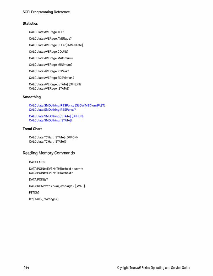
Statistics
CALCulate:AVERage:ALL?
CALCulate:AVERage:AVERage?
CALCulate:AVERage:CLEar[:IMMediate]
CALCulate:AVERage:COUNt?
CALCulate:AVERage:MAXimum?
CALCulate:AVERage:MINimum?
CALCulate:AVERage:PTPeak?
CALCulate:AVERage:SDEViation?
CALCulate:AVERage[:STATe] OFF|ONCALCulate:AVERage[:STATe]?
Smoothing
CALCulate:SMOothing:RESPonse SLOW|MEDium|FASTCALCulate:SMOothing:RESPonse?
CALCulate:SMOothing[:STATe] OFF|ONCALCulate:SMOothing[:STATe]?
Trend Chart
CALCulate:TCHart[:STATe] OFF|ONCALCulate:TCHart[:STATe]?
Reading Memory Commands
DATA:LAST?
DATA:POINts:EVENt:THReshold <count>DATA:POINts:EVENt:THReshold?
DATA:POINts?
DATA:REMove? <num_readings> [,WAIT]
FETCh?
R? [<max_readings>]
SCPI Programming Reference
444 Keysight Truevolt Series Operating and Service Guide
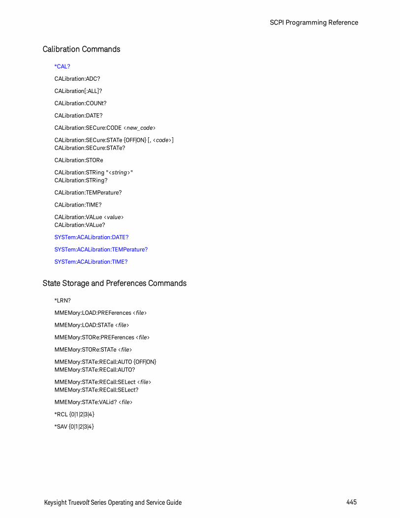
Calibration Commands
*CAL?
CALibration:ADC?
CALibration[:ALL]?
CALibration:COUNt?
CALibration:DATE?
CALibration:SECure:CODE <new_code>
CALibration:SECure:STATe OFF|ON [, <code>]CALibration:SECure:STATe?
CALibration:STORe
CALibration:STRing "<string>"CALibration:STRing?
CALibration:TEMPerature?
CALibration:TIME?
CALibration:VALue <value>CALibration:VALue?
SYSTem:ACALibration:DATE?
SYSTem:ACALibration:TEMPerature?
SYSTem:ACALibration:TIME?
State Storage and Preferences Commands
*LRN?
MMEMory:LOAD:PREFerences <file>
MMEMory:LOAD:STATe <file>
MMEMory:STORe:PREFerences <file>
MMEMory:STORe:STATe <file>
MMEMory:STATe:RECall:AUTO OFF|ONMMEMory:STATe:RECall:AUTO?
MMEMory:STATe:RECall:SELect <file>MMEMory:STATe:RECall:SELect?
MMEMory:STATe:VALid? <file>
*RCL 0|1|2|3|4
*SAV 0|1|2|3|4
Keysight Truevolt Series Operating and Service Guide 445
SCPI Programming Reference
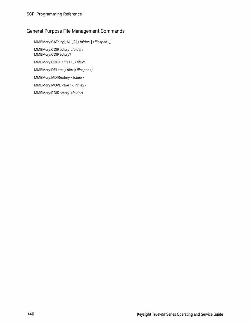
General Purpose File Management Commands
MMEMory:CATalog[:ALL]? [<folder>[<filespec>]]
MMEMory:CDIRectory <folder>MMEMory:CDIRectory?
MMEMory:COPY <file1>, <file2>
MMEMory:DELete <file>|<filespec>
MMEMory:MDIRectory <folder>
MMEMory:MOVE <file1>, <file2>
MMEMory:RDIRectory <folder>
SCPI Programming Reference
446 Keysight Truevolt Series Operating and Service Guide
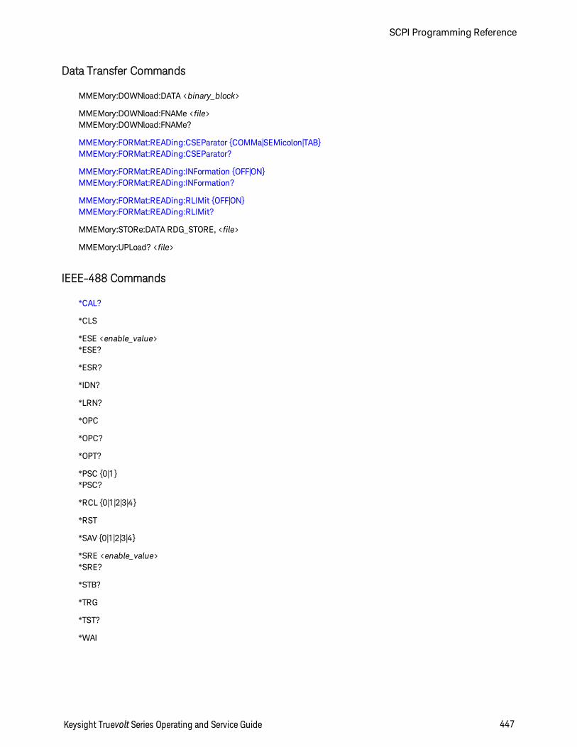
Data Transfer Commands
MMEMory:DOWNload:DATA <binary_block>
MMEMory:DOWNload:FNAMe <file>MMEMory:DOWNload:FNAMe?
MMEMory:FORMat:READing:CSEParator COMMa|SEMicolon|TABMMEMory:FORMat:READing:CSEParator?
MMEMory:FORMat:READing:INFormation OFF|ONMMEMory:FORMat:READing:INFormation?
MMEMory:FORMat:READing:RLIMit OFF|ONMMEMory:FORMat:READing:RLIMit?
MMEMory:STORe:DATA RDG_STORE, <file>
MMEMory:UPLoad? <file>
IEEE-488 Commands
*CAL?
*CLS
*ESE <enable_value>*ESE?
*ESR?
*IDN?
*LRN?
*OPC
*OPC?
*OPT?
*PSC 0|1*PSC?
*RCL 0|1|2|3|4
*RST
*SAV 0|1|2|3|4
*SRE <enable_value>*SRE?
*STB?
*TRG
*TST?
*WAI
Keysight Truevolt Series Operating and Service Guide 447
SCPI Programming Reference
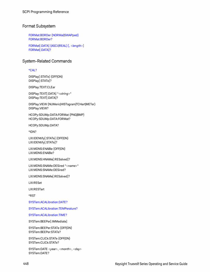
Format Subsystem
FORMat:BORDer NORMal|SWAPpedFORMat:BORDer?
FORMat[:DATA] ASCii|REAL [, <length>]FORMat[:DATA]?
System-Related Commands
*CAL?
DISPlay[:STATe] OFF|ONDISPlay[:STATe]?
DISPlay:TEXT:CLEar
DISPlay:TEXT[:DATA] "<string>"DISPlay:TEXT[:DATA]?
DISPlay:VIEW NUMeric|HISTogram|TCHart|METerDISPlay:VIEW?
HCOPy:SDUMp:DATA:FORMat PNG|BMPHCOPy:SDUMp:DATA:FORMat?
HCOPy:SDUMp:DATA?
*IDN?
LXI:IDENtify[:STATe] OFF|ONLXI:IDENtify[:STATe]?
LXI:MDNS:ENABle OFF|ONLXI:MDNS:ENABle?
LXI:MDNS:HNAMe[:RESolved]?
LXI:MDNS:SNAMe:DESired "<name>"LXI:MDNS:SNAMe:DESired?
LXI:MDNS:SNAMe[:RESolved]?
LXI:RESet
LXI:RESTart
*RST
SYSTem:ACALibration:DATE?
SYSTem:ACALibration:TEMPerature?
SYSTem:ACALibration:TIME?
SYSTem:BEEPer[:IMMediate]
SYSTem:BEEPer:STATe OFF|ONSYSTem:BEEPer:STATe?
SYSTem:CLICk:STATe OFF|ONSYSTem:CLICk:STATe?
SYSTem:DATE <year>, <month>, <day>SYSTem:DATE?
SCPI Programming Reference
448 Keysight Truevolt Series Operating and Service Guide
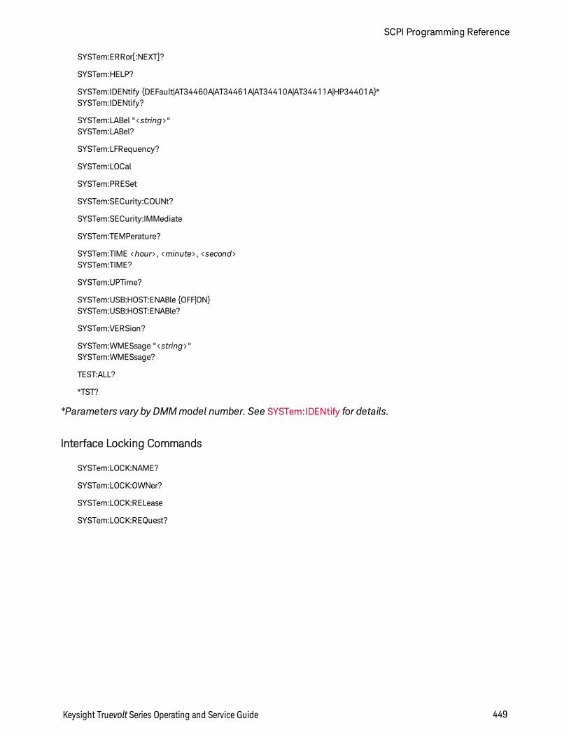
SYSTem:ERRor[:NEXT]?
SYSTem:HELP?
SYSTem:IDENtify DEFault|AT34460A|AT34461A|AT34410A|AT34411A|HP34401A*SYSTem:IDENtify?
SYSTem:LABel "<string>"SYSTem:LABel?
SYSTem:LFRequency?
SYSTem:LOCal
SYSTem:PRESet
SYSTem:SECurity:COUNt?
SYSTem:SECurity:IMMediate
SYSTem:TEMPerature?
SYSTem:TIME <hour>, <minute>, <second>SYSTem:TIME?
SYSTem:UPTime?
SYSTem:USB:HOST:ENABle OFF|ONSYSTem:USB:HOST:ENABle?
SYSTem:VERSion?
SYSTem:WMESsage "<string>"SYSTem:WMESsage?
TEST:ALL?
*TST?
*Parameters vary by DMMmodel number. See SYSTem:IDENtify for details.
Interface Locking Commands
SYSTem:LOCK:NAME?
SYSTem:LOCK:OWNer?
SYSTem:LOCK:RELease
SYSTem:LOCK:REQuest?
Keysight Truevolt Series Operating and Service Guide 449
SCPI Programming Reference
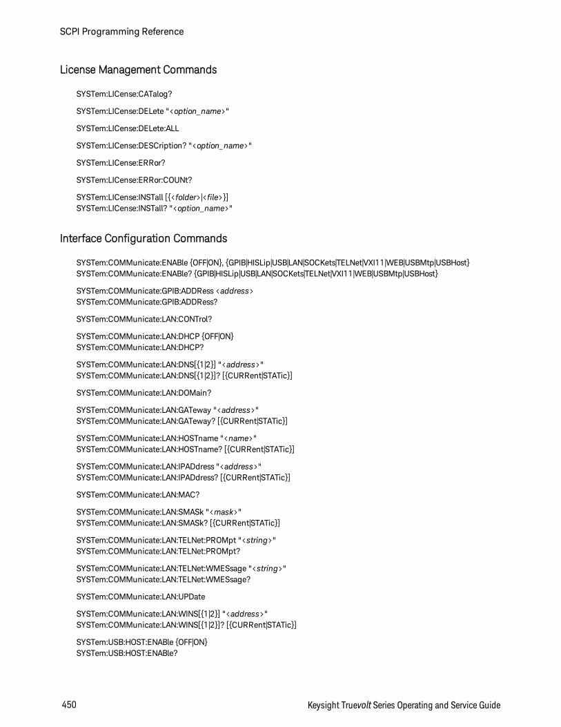
License Management Commands
SYSTem:LICense:CATalog?
SYSTem:LICense:DELete "<option_name>"
SYSTem:LICense:DELete:ALL
SYSTem:LICense:DESCription? "<option_name>"
SYSTem:LICense:ERRor?
SYSTem:LICense:ERRor:COUNt?
SYSTem:LICense:INSTall [<folder>|<file>]SYSTem:LICense:INSTall? "<option_name>"
Interface Configuration Commands
SYSTem:COMMunicate:ENABle OFF|ON, GPIB|HISLip|USB|LAN|SOCKets|TELNet|VXI11|WEB|USBMtp|USBHostSYSTem:COMMunicate:ENABle? GPIB|HISLip|USB|LAN|SOCKets|TELNet|VXI11|WEB|USBMtp|USBHost
SYSTem:COMMunicate:GPIB:ADDRess <address>SYSTem:COMMunicate:GPIB:ADDRess?
SYSTem:COMMunicate:LAN:CONTrol?
SYSTem:COMMunicate:LAN:DHCP OFF|ONSYSTem:COMMunicate:LAN:DHCP?
SYSTem:COMMunicate:LAN:DNS[1|2] "<address>"SYSTem:COMMunicate:LAN:DNS[1|2]? [CURRent|STATic]
SYSTem:COMMunicate:LAN:DOMain?
SYSTem:COMMunicate:LAN:GATeway "<address>"SYSTem:COMMunicate:LAN:GATeway? [CURRent|STATic]
SYSTem:COMMunicate:LAN:HOSTname "<name>"SYSTem:COMMunicate:LAN:HOSTname? [CURRent|STATic]
SYSTem:COMMunicate:LAN:IPADdress "<address>"SYSTem:COMMunicate:LAN:IPADdress? [CURRent|STATic]
SYSTem:COMMunicate:LAN:MAC?
SYSTem:COMMunicate:LAN:SMASk "<mask>"SYSTem:COMMunicate:LAN:SMASk? [CURRent|STATic]
SYSTem:COMMunicate:LAN:TELNet:PROMpt "<string>"SYSTem:COMMunicate:LAN:TELNet:PROMpt?
SYSTem:COMMunicate:LAN:TELNet:WMESsage "<string>"SYSTem:COMMunicate:LAN:TELNet:WMESsage?
SYSTem:COMMunicate:LAN:UPDate
SYSTem:COMMunicate:LAN:WINS[1|2] "<address>"SYSTem:COMMunicate:LAN:WINS[1|2]? [CURRent|STATic]
SYSTem:USB:HOST:ENABle OFF|ONSYSTem:USB:HOST:ENABle?
SCPI Programming Reference
450 Keysight Truevolt Series Operating and Service Guide
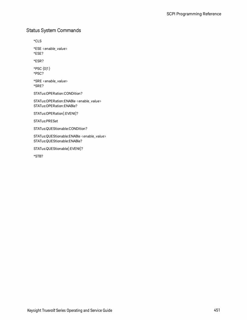
Status System Commands
*CLS
*ESE <enable_value>*ESE?
*ESR?
*PSC 0|1*PSC?
*SRE <enable_value>*SRE?
STATus:OPERation:CONDition?
STATus:OPERation:ENABle <enable_value>STATus:OPERation:ENABle?
STATus:OPERation[:EVENt]?
STATus:PRESet
STATus:QUEStionable:CONDition?
STATus:QUEStionable:ENABle <enable_value>STATus:QUEStionable:ENABle?
STATus:QUEStionable[:EVENt]?
*STB?
Keysight Truevolt Series Operating and Service Guide 451
SCPI Programming Reference
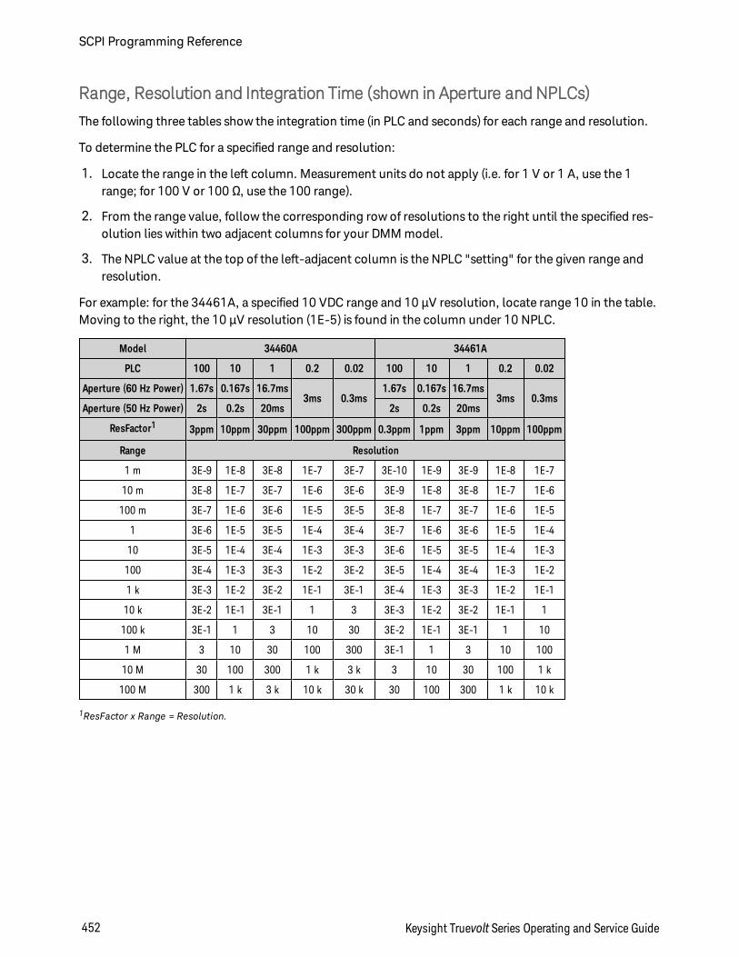
Range, Resolution and Integration Time (shown in Aperture and NPLCs)
The following three tables show the integration time (in PLC and seconds) for each range and resolution.
To determine the PLC for a specified range and resolution:
1. Locate the range in the left column. Measurement units do not apply (i.e. for 1 V or 1 A, use the 1range; for 100 V or 100 Ω, use the 100 range).
2. From the range value, follow the corresponding row of resolutions to the right until the specified res-olution lies within two adjacent columns for your DMM model.
3. The NPLC value at the top of the left-adjacent column is the NPLC "setting" for the given range andresolution.
For example: for the 34461A, a specified 10 VDC range and 10 µV resolution, locate range 10 in the table.Moving to the right, the 10 µV resolution (1E-5) is found in the column under 10 NPLC.
Model 34460A 34461A
PLC 100 10 1 0.2 0.02 100 10 1 0.2 0.02
Aperture (60 Hz Power) 1.67s 0.167s 16.7ms3ms 0.3ms
1.67s 0.167s 16.7ms3ms 0.3ms
Aperture (50 Hz Power) 2s 0.2s 20ms 2s 0.2s 20ms
ResFactor1 3ppm 10ppm 30ppm 100ppm 300ppm 0.3ppm 1ppm 3ppm 10ppm 100ppm
Range Resolution
1 m 3E-9 1E-8 3E-8 1E-7 3E-7 3E-10 1E-9 3E-9 1E-8 1E-7
10 m 3E-8 1E-7 3E-7 1E-6 3E-6 3E-9 1E-8 3E-8 1E-7 1E-6
100 m 3E-7 1E-6 3E-6 1E-5 3E-5 3E-8 1E-7 3E-7 1E-6 1E-5
1 3E-6 1E-5 3E-5 1E-4 3E-4 3E-7 1E-6 3E-6 1E-5 1E-4
10 3E-5 1E-4 3E-4 1E-3 3E-3 3E-6 1E-5 3E-5 1E-4 1E-3
100 3E-4 1E-3 3E-3 1E-2 3E-2 3E-5 1E-4 3E-4 1E-3 1E-2
1 k 3E-3 1E-2 3E-2 1E-1 3E-1 3E-4 1E-3 3E-3 1E-2 1E-1
10 k 3E-2 1E-1 3E-1 1 3 3E-3 1E-2 3E-2 1E-1 1
100 k 3E-1 1 3 10 30 3E-2 1E-1 3E-1 1 10
1 M 3 10 30 100 300 3E-1 1 3 10 100
10 M 30 100 300 1 k 3 k 3 10 30 100 1 k
100 M 300 1 k 3 k 10 k 30 k 30 100 300 1 k 10 k
1ResFactor x Range = Resolution.
SCPI Programming Reference
452 Keysight Truevolt Series Operating and Service Guide
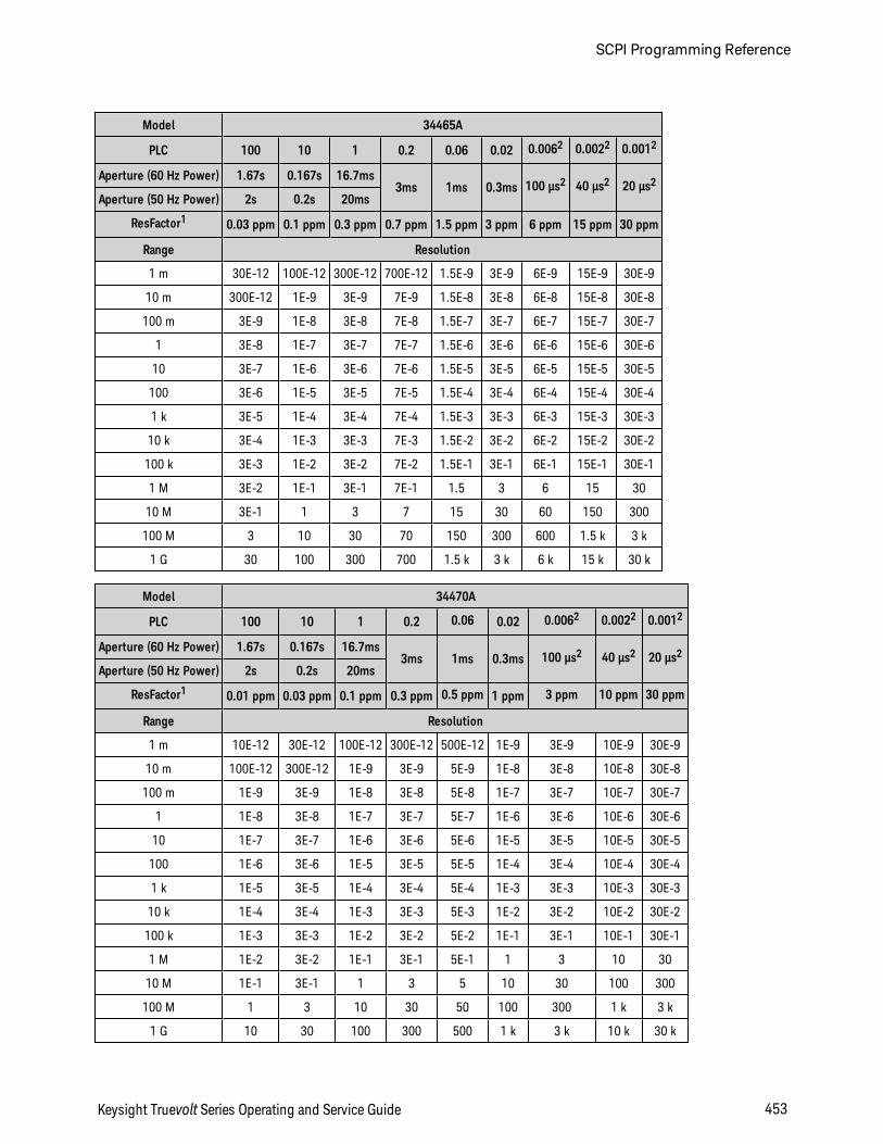
Model 34465A
PLC 100 10 1 0.2 0.06 0.02 0.0062 0.0022 0.0012
Aperture (60 Hz Power) 1.67s 0.167s 16.7ms3ms 1ms 0.3ms 100 µs2 40 µs2 20 µs2
Aperture (50 Hz Power) 2s 0.2s 20ms
ResFactor1 0.03 ppm 0.1 ppm 0.3 ppm 0.7 ppm 1.5 ppm 3 ppm 6 ppm 15 ppm 30 ppm
Range Resolution
1 m 30E-12 100E-12 300E-12 700E-12 1.5E-9 3E-9 6E-9 15E-9 30E-9
10 m 300E-12 1E-9 3E-9 7E-9 1.5E-8 3E-8 6E-8 15E-8 30E-8
100 m 3E-9 1E-8 3E-8 7E-8 1.5E-7 3E-7 6E-7 15E-7 30E-7
1 3E-8 1E-7 3E-7 7E-7 1.5E-6 3E-6 6E-6 15E-6 30E-6
10 3E-7 1E-6 3E-6 7E-6 1.5E-5 3E-5 6E-5 15E-5 30E-5
100 3E-6 1E-5 3E-5 7E-5 1.5E-4 3E-4 6E-4 15E-4 30E-4
1 k 3E-5 1E-4 3E-4 7E-4 1.5E-3 3E-3 6E-3 15E-3 30E-3
10 k 3E-4 1E-3 3E-3 7E-3 1.5E-2 3E-2 6E-2 15E-2 30E-2
100 k 3E-3 1E-2 3E-2 7E-2 1.5E-1 3E-1 6E-1 15E-1 30E-1
1 M 3E-2 1E-1 3E-1 7E-1 1.5 3 6 15 30
10 M 3E-1 1 3 7 15 30 60 150 300
100 M 3 10 30 70 150 300 600 1.5 k 3 k
1 G 30 100 300 700 1.5 k 3 k 6 k 15 k 30 k
Model 34470A
PLC 100 10 1 0.2 0.06 0.02 0.0062 0.0022 0.0012
Aperture (60 Hz Power) 1.67s 0.167s 16.7ms3ms 1ms 0.3ms 100 µs2 40 µs2 20 µs2
Aperture (50 Hz Power) 2s 0.2s 20ms
ResFactor1 0.01 ppm 0.03 ppm 0.1 ppm 0.3 ppm 0.5 ppm 1 ppm 3 ppm 10 ppm 30 ppm
Range Resolution
1 m 10E-12 30E-12 100E-12 300E-12 500E-12 1E-9 3E-9 10E-9 30E-9
10 m 100E-12 300E-12 1E-9 3E-9 5E-9 1E-8 3E-8 10E-8 30E-8
100 m 1E-9 3E-9 1E-8 3E-8 5E-8 1E-7 3E-7 10E-7 30E-7
1 1E-8 3E-8 1E-7 3E-7 5E-7 1E-6 3E-6 10E-6 30E-6
10 1E-7 3E-7 1E-6 3E-6 5E-6 1E-5 3E-5 10E-5 30E-5
100 1E-6 3E-6 1E-5 3E-5 5E-5 1E-4 3E-4 10E-4 30E-4
1 k 1E-5 3E-5 1E-4 3E-4 5E-4 1E-3 3E-3 10E-3 30E-3
10 k 1E-4 3E-4 1E-3 3E-3 5E-3 1E-2 3E-2 10E-2 30E-2
100 k 1E-3 3E-3 1E-2 3E-2 5E-2 1E-1 3E-1 10E-1 30E-1
1 M 1E-2 3E-2 1E-1 3E-1 5E-1 1 3 10 30
10 M 1E-1 3E-1 1 3 5 10 30 100 300
100 M 1 3 10 30 50 100 300 1 k 3 k
1 G 10 30 100 300 500 1 k 3 k 10 k 30 k
Keysight Truevolt Series Operating and Service Guide 453
SCPI Programming Reference

1ResFactor x Range = Resolution., 2 34465A/70A with DIG option only.
SCPI Programming Reference
454 Keysight Truevolt Series Operating and Service Guide
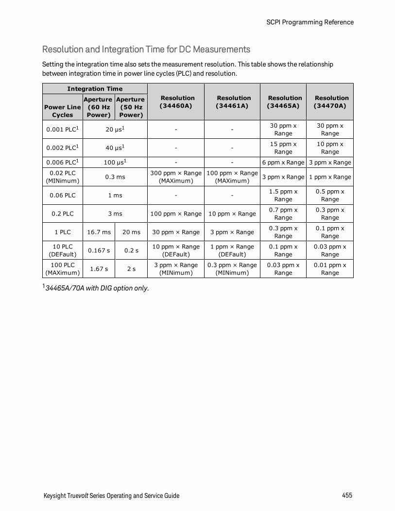
Resolution and Integration Time for DCMeasurements
Setting the integration time also sets the measurement resolution. This table shows the relationshipbetween integration time in power line cycles (PLC) and resolution.
Integration TimeResolution(34460A)
Resolution(34461A)
Resolution(34465A)
Resolution(34470A)Power Line
Cycles
Aperture(60 HzPower)
Aperture(50 HzPower)
0.001 PLC1 20 µs1 - - 30 ppm xRange
30 ppm xRange
0.002 PLC1 40 µs1 - - 15 ppm xRange
10 ppm xRange
0.006 PLC1 100 µs1 - - 6 ppm x Range 3 ppm x Range
0.02 PLC(MINimum) 0.3 ms 300 ppm × Range
(MAXimum)100 ppm × Range
(MAXimum) 3 ppm x Range 1 ppm x Range
0.06 PLC 1 ms - - 1.5 ppm xRange
0.5 ppm xRange
0.2 PLC 3 ms 100 ppm × Range 10 ppm × Range 0.7 ppm xRange
0.3 ppm xRange
1 PLC 16.7 ms 20 ms 30 ppm × Range 3 ppm × Range 0.3 ppm xRange
0.1 ppm xRange
10 PLC(DEFault) 0.167 s 0.2 s 10 ppm × Range
(DEFault)1 ppm × Range
(DEFault)0.1 ppm x
Range0.03 ppm x
Range
100 PLC(MAXimum) 1.67 s 2 s 3 ppm × Range
(MINimum)0.3 ppm × Range
(MINimum)0.03 ppm x
Range0.01 ppm x
Range
134465A/70A with DIG option only.
Keysight Truevolt Series Operating and Service Guide 455
SCPI Programming Reference
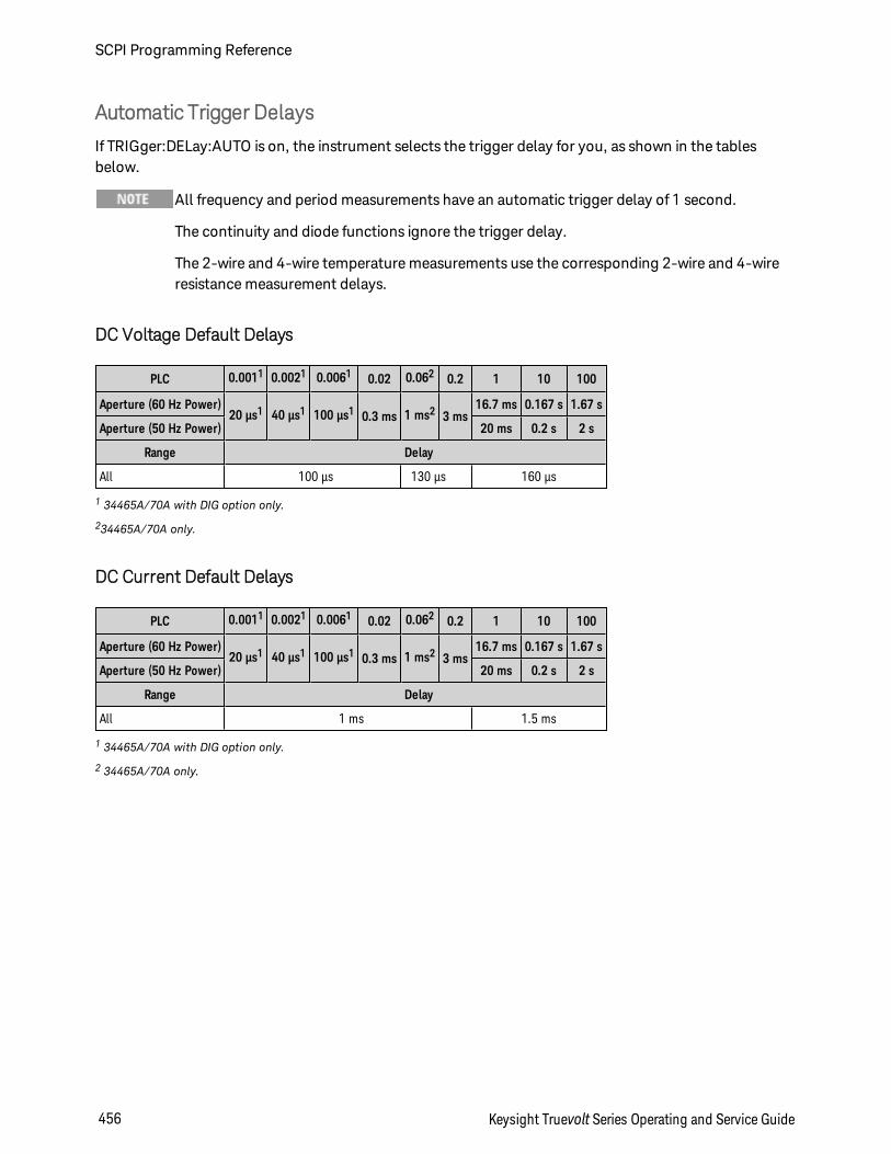
Automatic Trigger Delays
If TRIGger:DELay:AUTO is on, the instrument selects the trigger delay for you, as shown in the tablesbelow.
All frequency and period measurements have an automatic trigger delay of 1 second.
The continuity and diode functions ignore the trigger delay.
The 2-wire and 4-wire temperature measurements use the corresponding 2-wire and 4-wireresistance measurement delays.
DC Voltage Default Delays
PLC 0.0011 0.0021 0.0061 0.02 0.062 0.2 1 10 100
Aperture (60 Hz Power)20 µs1 40 µs1 100 µs1 0.3 ms 1 ms2 3 ms
16.7 ms 0.167 s 1.67 s
Aperture (50 Hz Power) 20 ms 0.2 s 2 s
Range Delay
All 100 µs 130 µs 160 µs
1 34465A/70A with DIG option only.
234465A/70A only.
DC Current Default Delays
PLC 0.0011 0.0021 0.0061 0.02 0.062 0.2 1 10 100
Aperture (60 Hz Power)20 µs1 40 µs1 100 µs1 0.3 ms 1 ms2 3 ms
16.7 ms 0.167 s 1.67 s
Aperture (50 Hz Power) 20 ms 0.2 s 2 s
Range Delay
All 1 ms 1.5 ms
1 34465A/70A with DIG option only.
2 34465A/70A only.
SCPI Programming Reference
456 Keysight Truevolt Series Operating and Service Guide
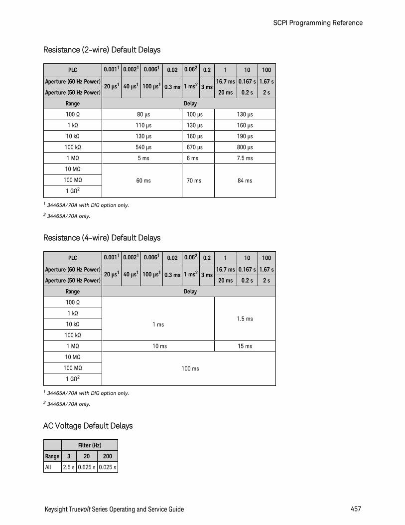
Resistance (2-wire) Default Delays
PLC 0.0011 0.0021 0.0061 0.02 0.062 0.2 1 10 100
Aperture (60 Hz Power)20 µs1 40 µs1 100 µs1 0.3 ms 1 ms2 3 ms
16.7 ms 0.167 s 1.67 s
Aperture (50 Hz Power) 20 ms 0.2 s 2 s
Range Delay
100 Ω 80 µs 100 µs 130 µs
1 kΩ 110 µs 130 µs 160 µs
10 kΩ 130 µs 160 µs 190 µs
100 kΩ 540 µs 670 µs 800 µs
1 MΩ 5 ms 6 ms 7.5 ms
10 MΩ
60 ms 70 ms 84 ms100 MΩ
1 GΩ2
1 34465A/70A with DIG option only.
2 34465A/70A only.
Resistance (4-wire) Default Delays
PLC 0.0011 0.0021 0.0061 0.02 0.062 0.2 1 10 100
Aperture (60 Hz Power)20 µs1 40 µs1 100 µs1 0.3 ms 1 ms2 3 ms
16.7 ms 0.167 s 1.67 s
Aperture (50 Hz Power) 20 ms 0.2 s 2 s
Range Delay
100 Ω
1 ms1.5 ms
1 kΩ
10 kΩ
100 kΩ
1 MΩ 10 ms 15 ms
10 MΩ
100 ms100 MΩ
1 GΩ2
1 34465A/70A with DIG option only.
2 34465A/70A only.
AC Voltage Default Delays
Filter (Hz)
Range 3 20 200
All 2.5 s 0.625 s 0.025 s
Keysight Truevolt Series Operating and Service Guide 457
SCPI Programming Reference
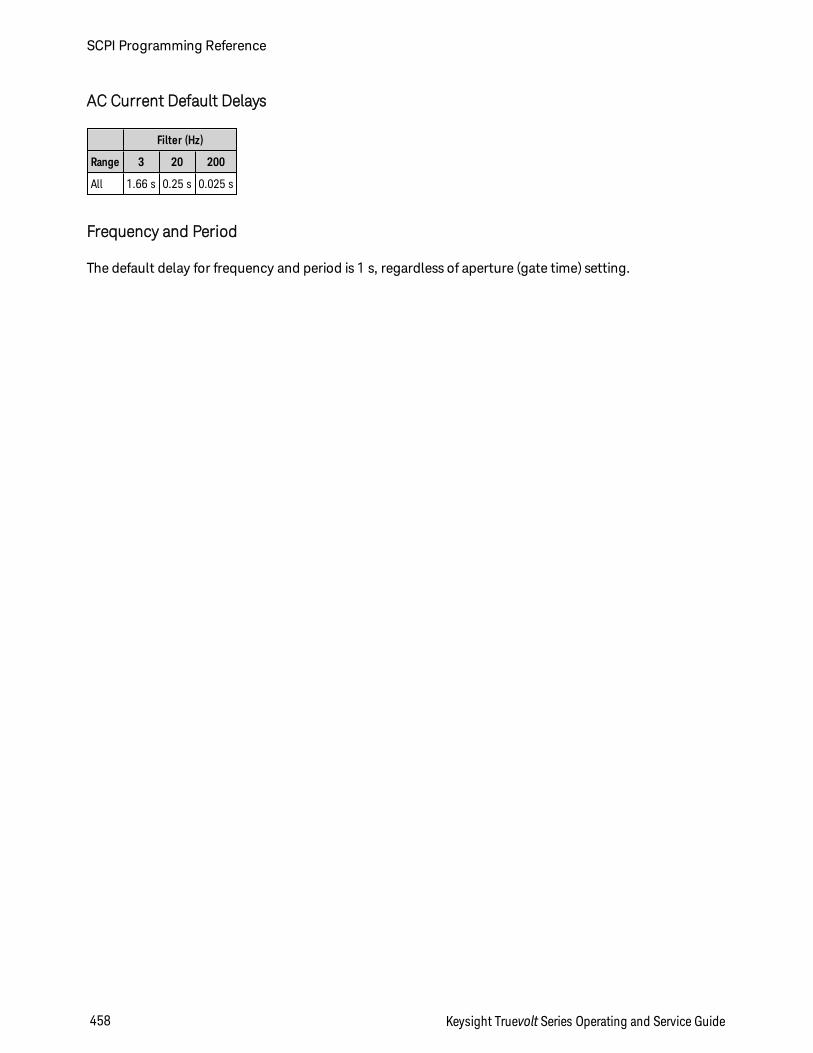
AC Current Default Delays
Filter (Hz)
Range 3 20 200
All 1.66 s 0.25 s 0.025 s
Frequency and Period
The default delay for frequency and period is 1 s, regardless of aperture (gate time) setting.
SCPI Programming Reference
458 Keysight Truevolt Series Operating and Service Guide
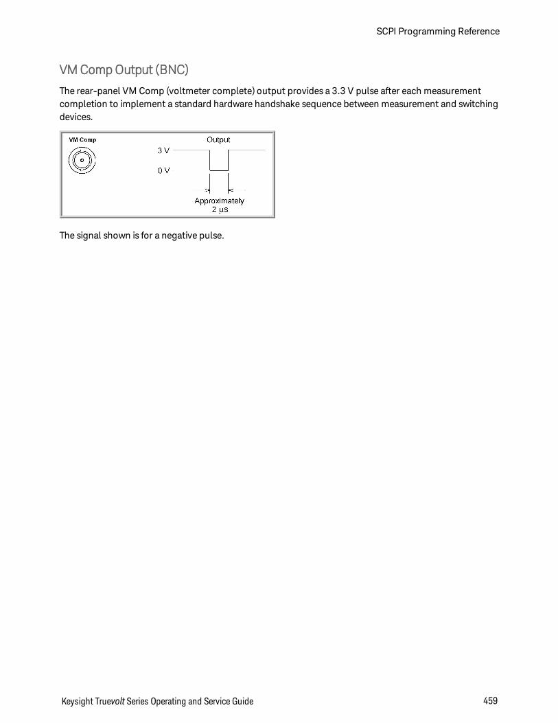
VMCompOutput (BNC)
The rear-panel VM Comp (voltmeter complete) output provides a 3.3 V pulse after each measurementcompletion to implement a standard hardware handshake sequence between measurement and switchingdevices.
The signal shown is for a negative pulse.
Keysight Truevolt Series Operating and Service Guide 459
SCPI Programming Reference
SCPI Error Messages
Command Errors (-100…)
Execution Errors (-200…)
Device-Specific Errors (-300…)
Query Errors (-400…)
Network Errors (+100...)
Instrument Errors (+200…)
Miscellaneous Errors (+300... and +500..)
Licensing and Self-test Errors (+600...)
Calibration Errors (+700…)
Miscellaneous Errors (+800...)
The instrument returns error messages in accordance with the SCPI standard.
l Up to 20 errors can be stored in the instrument's error queue. Each remote interface I/O session(GPIB, USB, VXI-11, Telnet/Sockets) has its own interface-specific error queue. Errors appear in theerror queue of the I/O session that caused the error. For example, if an error was generated by a com-mand sent over GPIB, send SYSTem:ERRor? from GPIB to read the error queue. Errors generated byinstrument hardware are broadcast to all I/O sessions.
l The instrument beeps each time an error is generated (unless disabled by SYSTem:BEEPer:STATe OFF).The front panel Error annunciator turns on when one or more errors are in the error queue.
l A special global error queue holds all power-on and hardware-related errors (for example, over-temperature).
l Error retrieval is first-in-first-out (FIFO), and errors are cleared as you read them. When you have readall of the interface-specific errors, the errors in the global error queue are retrieved. When you haveread all errors from the interface-specific and global error queues, the Error annunciator turns off.
l If more than 20 errors have occurred, the most recent error stored in the queue is replaced with -350,"Queue overflow". No additional errors are stored until you remove errors from the queue. If noerrors have occurred when you read the error queue, the instrument responds with +0,"No error".
l The front panel reports errors from all I/O sessions and the global error queue. To read the error queuefrom the front panel, press Help > View remote command error queue.
l Error conditions are also summarized in the Status Byte Register. For more information on the SCPIStatus System, see Status Subsystem Introduction.
l The interface-specific error queues are cleared by the *CLS (Clear Status) command and when power iscycled. All errors are cleared when you read the error queue. The error queue is not cleared by a Fact-ory Reset (*RST) or an Instrument Preset (SYSTem:PRESet).
SCPI Programming Reference
460 Keysight Truevolt Series Operating and Service Guide

l Front Panel:If the Error annunciator is on, there are errors in the error queue. The Remote annunciator is likely onas well. Press the Local key to return to local operation (the Remote annunciator goes off). Then press[Help], select "View remote command error queue" in the menu and press Select. Use the menu nav-igation "arrow" keys to view the error messages. Press Back to exit and clear the error queue.
l SCPI:SYSTem:ERRor? Read and clear one error from the queue
Errors have the following format (the error string may contain up to 80 characters):-113,"Undefined header"
Keysight Truevolt Series Operating and Service Guide 461
SCPI Programming Reference
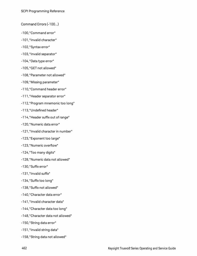
Command Errors (-100…)
-100,"Command error"
-101,"Invalid character"
-102,"Syntax error"
-103,"Invalid separator"
-104,"Data type error"
-105,"GET not allowed"
-108,"Parameter not allowed"
-109,"Missing parameter"
-110,"Command header error"
-111,"Header separator error"
-112,"Program mnemonic too long"
-113,"Undefined header"
-114,"Header suffix out of range"
-120,"Numeric data error"
-121,"Invalid character in number"
-123,"Exponent too large"
-123,"Numeric overflow"
-124,"Too many digits"
-128,"Numeric data not allowed"
-130,"Suffix error"
-131,"Invalid suffix"
-134,"Suffix too long"
-138,"Suffix not allowed"
-140,"Character data error"
-141,"Invalid character data"
-144,"Character data too long"
-148,"Character data not allowed"
-150,"String data error"
-151,"Invalid string data"
-158,"String data not allowed"
SCPI Programming Reference
462 Keysight Truevolt Series Operating and Service Guide

-160,"Block data error"
-161,"Invalid block data"
-168,"Block data not allowed"
Keysight Truevolt Series Operating and Service Guide 463
SCPI Programming Reference
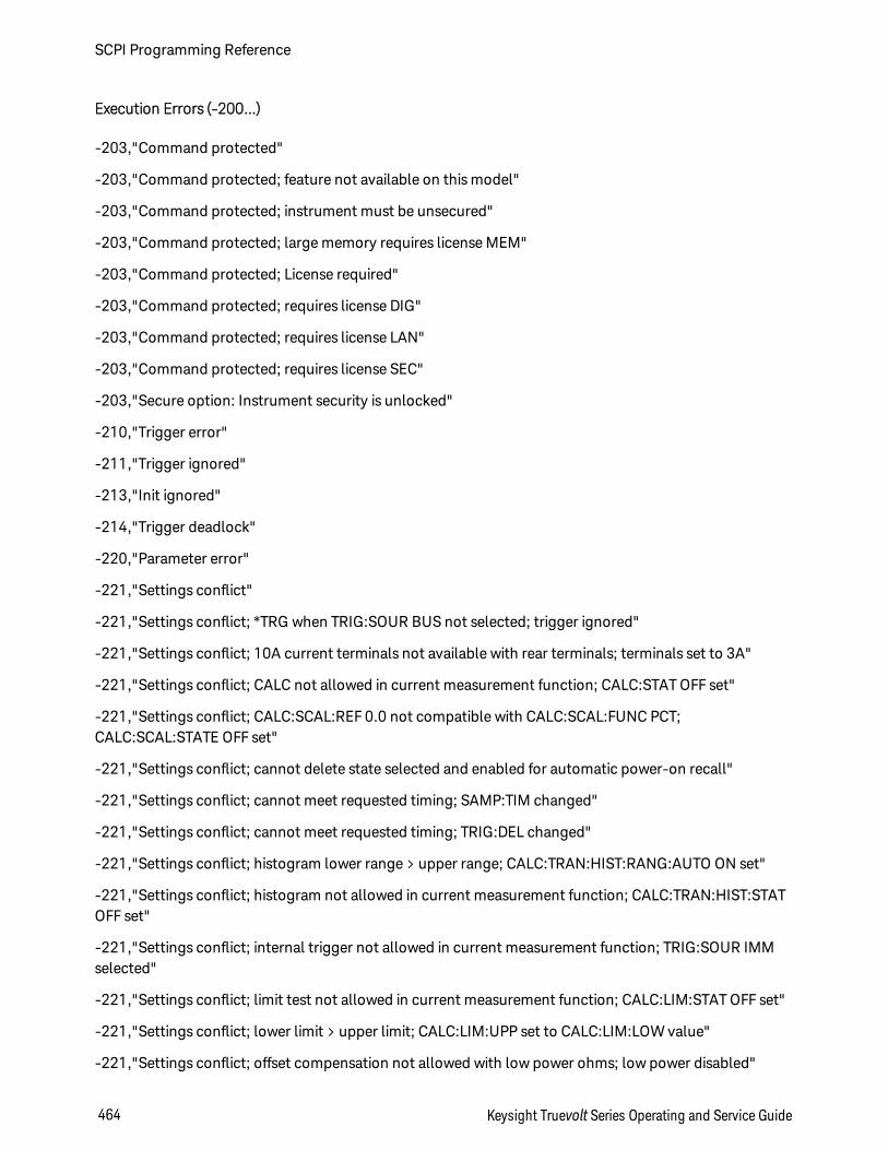
Execution Errors (-200…)
-203,"Command protected"
-203,"Command protected; feature not available on this model"
-203,"Command protected; instrument must be unsecured"
-203,"Command protected; large memory requires license MEM"
-203,"Command protected; License required"
-203,"Command protected; requires license DIG"
-203,"Command protected; requires license LAN"
-203,"Command protected; requires license SEC"
-203,"Secure option: Instrument security is unlocked"
-210,"Trigger error"
-211,"Trigger ignored"
-213,"Init ignored"
-214,"Trigger deadlock"
-220,"Parameter error"
-221,"Settings conflict"
-221,"Settings conflict; *TRG when TRIG:SOUR BUS not selected; trigger ignored"
-221,"Settings conflict; 10A current terminals not available with rear terminals; terminals set to 3A"
-221,"Settings conflict; CALC not allowed in current measurement function; CALC:STAT OFF set"
-221,"Settings conflict; CALC:SCAL:REF 0.0 not compatible with CALC:SCAL:FUNC PCT;CALC:SCAL:STATE OFF set"
-221,"Settings conflict; cannot delete state selected and enabled for automatic power-on recall"
-221,"Settings conflict; cannot meet requested timing; SAMP:TIM changed"
-221,"Settings conflict; cannot meet requested timing; TRIG:DEL changed"
-221,"Settings conflict; histogram lower range > upper range; CALC:TRAN:HIST:RANG:AUTO ON set"
-221,"Settings conflict; histogram not allowed in current measurement function; CALC:TRAN:HIST:STATOFF set"
-221,"Settings conflict; internal trigger not allowed in current measurement function; TRIG:SOUR IMMselected"
-221,"Settings conflict; limit test not allowed in current measurement function; CALC:LIM:STAT OFF set"
-221,"Settings conflict; lower limit > upper limit; CALC:LIM:UPP set to CALC:LIM:LOW value"
-221,"Settings conflict; offset compensation not allowed with low power ohms; low power disabled"
SCPI Programming Reference
464 Keysight Truevolt Series Operating and Service Guide
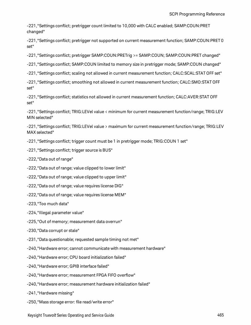
-221,"Settings conflict; pretrigger count limited to 10,000 with CALC enabled; SAMP:COUN:PRETchanged"
-221,"Settings conflict; pretrigger not supported on current measurement function; SAMP:COUN:PRET 0set"
-221,"Settings conflict; pretrigger SAMP:COUN:PRETrig >= SAMP:COUN; SAMP:COUN:PRET changed"
-221,"Settings conflict; SAMP:COUN limited to memory size in pretrigger mode; SAMP:COUN changed"
-221,"Settings conflict; scaling not allowed in current measurement function; CALC:SCAL:STAT OFF set"
-221,"Settings conflict; smoothing not allowed in current measurement function; CALC:SMO:STAT OFFset"
-221,"Settings conflict; statistics not allowed in current measurement function; CALC:AVER:STAT OFFset"
-221,"Settings conflict; TRIG:LEVel value < minimum for current measurement function/range; TRIG:LEVMIN selected"
-221,"Settings conflict; TRIG:LEVel value > maximum for current measurement function/range; TRIG:LEVMAX selected"
-221,"Settings conflict; trigger count must be 1 in pretrigger mode; TRIG:COUN 1 set"
-221,"Settings conflict; trigger source is BUS"
-222,"Data out of range"
-222,"Data out of range; value clipped to lower limit"
-222,"Data out of range; value clipped to upper limit"
-222,"Data out of range; value requires license DIG"
-222,"Data out of range; value requires license MEM"
-223,"Too much data"
-224,"Illegal parameter value"
-225,"Out of memory; measurement data overrun"
-230,"Data corrupt or stale"
-231,"Data questionable; requested sample timing not met"
-240,"Hardware error; cannot communicate with measurement hardware"
-240,"Hardware error; CPU board initialization failed"
-240,"Hardware error; GPIB interface failed"
-240,"Hardware error; measurement FPGA FIFO overflow"
-240,"Hardware error; measurement hardware initialization failed"
-241,"Hardware missing"
-250,"Mass storage error: file read/write error"
Keysight Truevolt Series Operating and Service Guide 465
SCPI Programming Reference
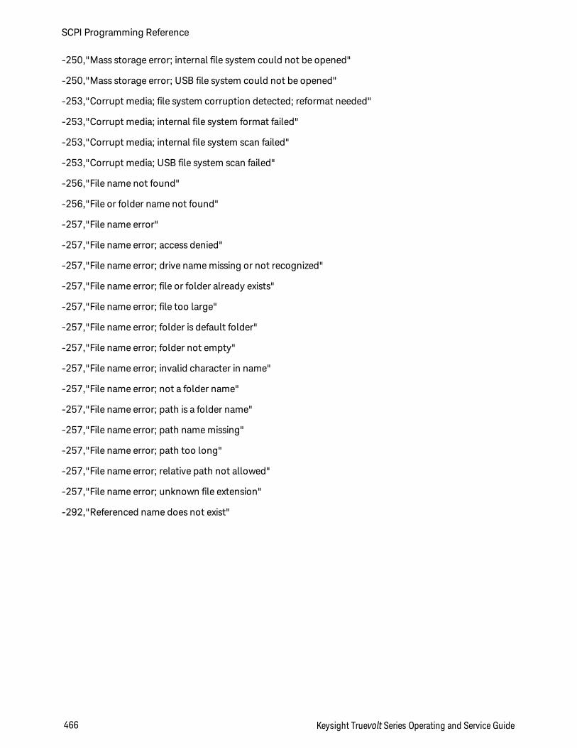
-250,"Mass storage error; internal file system could not be opened"
-250,"Mass storage error; USB file system could not be opened"
-253,"Corrupt media; file system corruption detected; reformat needed"
-253,"Corrupt media; internal file system format failed"
-253,"Corrupt media; internal file system scan failed"
-253,"Corrupt media; USB file system scan failed"
-256,"File name not found"
-256,"File or folder name not found"
-257,"File name error"
-257,"File name error; access denied"
-257,"File name error; drive name missing or not recognized"
-257,"File name error; file or folder already exists"
-257,"File name error; file too large"
-257,"File name error; folder is default folder"
-257,"File name error; folder not empty"
-257,"File name error; invalid character in name"
-257,"File name error; not a folder name"
-257,"File name error; path is a folder name"
-257,"File name error; path name missing"
-257,"File name error; path too long"
-257,"File name error; relative path not allowed"
-257,"File name error; unknown file extension"
-292,"Referenced name does not exist"
SCPI Programming Reference
466 Keysight Truevolt Series Operating and Service Guide
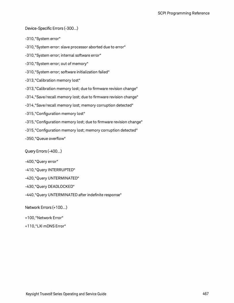
Device-Specific Errors (-300…)
-310,"System error"
-310,"System error: slave processor aborted due to error"
-310,"System error; internal software error"
-310,"System error; out of memory"
-310,"System error; software initialization failed"
-313,"Calibration memory lost"
-313,"Calibration memory lost; due to firmware revision change"
-314,"Save/recall memory lost; due to firmware revision change"
-314,"Save/recall memory lost; memory corruption detected"
-315,"Configuration memory lost"
-315,"Configuration memory lost; due to firmware revision change"
-315,"Configuration memory lost; memory corruption detected"
-350,"Queue overflow"
Query Errors (-400…)
-400,"Query error"
-410,"Query INTERRUPTED"
-420,"Query UNTERMINATED"
-430,"Query DEADLOCKED"
-440,"Query UNTERMINATED after indefinite response"
Network Errors (+100...)
+100,"Network Error"
+110,"LXI mDNS Error"
Keysight Truevolt Series Operating and Service Guide 467
SCPI Programming Reference
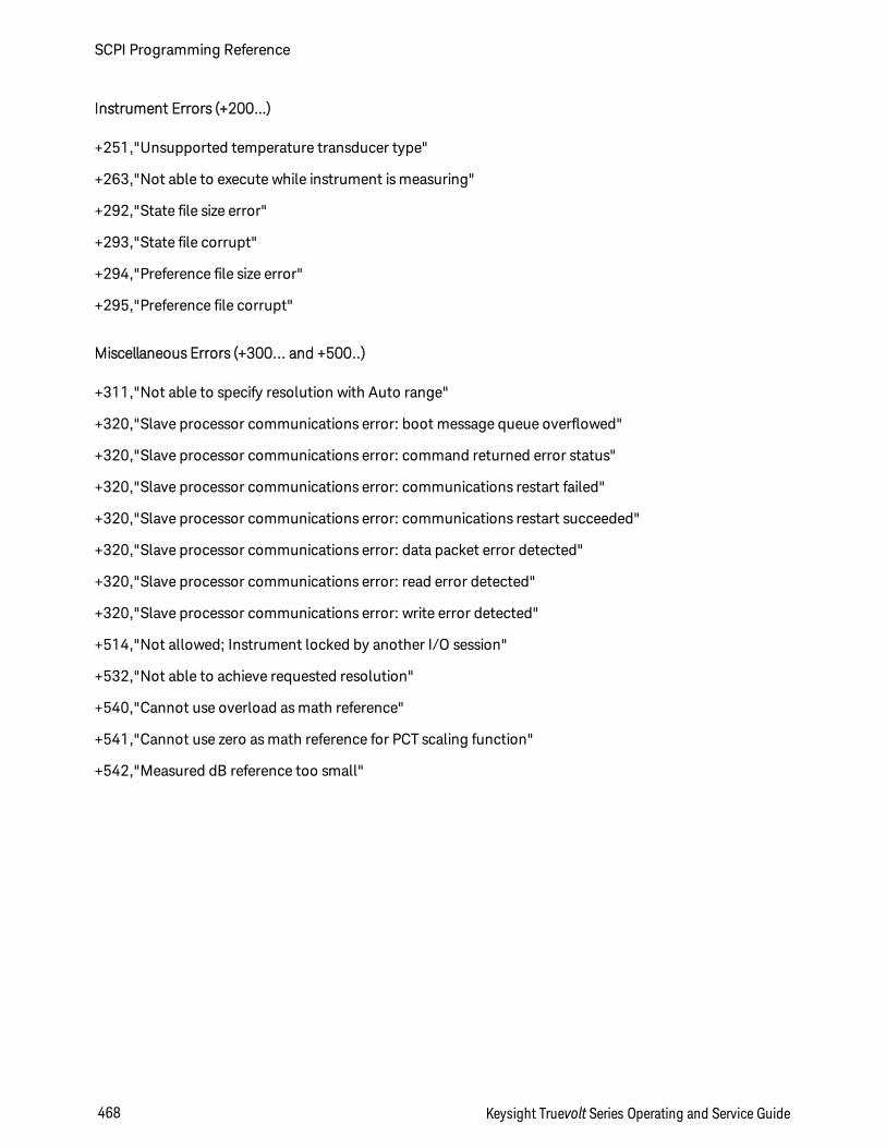
Instrument Errors (+200…)
+251,"Unsupported temperature transducer type"
+263,"Not able to execute while instrument is measuring"
+292,"State file size error"
+293,"State file corrupt"
+294,"Preference file size error"
+295,"Preference file corrupt"
Miscellaneous Errors (+300... and +500..)
+311,"Not able to specify resolution with Auto range"
+320,"Slave processor communications error: boot message queue overflowed"
+320,"Slave processor communications error: command returned error status"
+320,"Slave processor communications error: communications restart failed"
+320,"Slave processor communications error: communications restart succeeded"
+320,"Slave processor communications error: data packet error detected"
+320,"Slave processor communications error: read error detected"
+320,"Slave processor communications error: write error detected"
+514,"Not allowed; Instrument locked by another I/O session"
+532,"Not able to achieve requested resolution"
+540,"Cannot use overload as math reference"
+541,"Cannot use zero as math reference for PCT scaling function"
+542,"Measured dB reference too small"
SCPI Programming Reference
468 Keysight Truevolt Series Operating and Service Guide
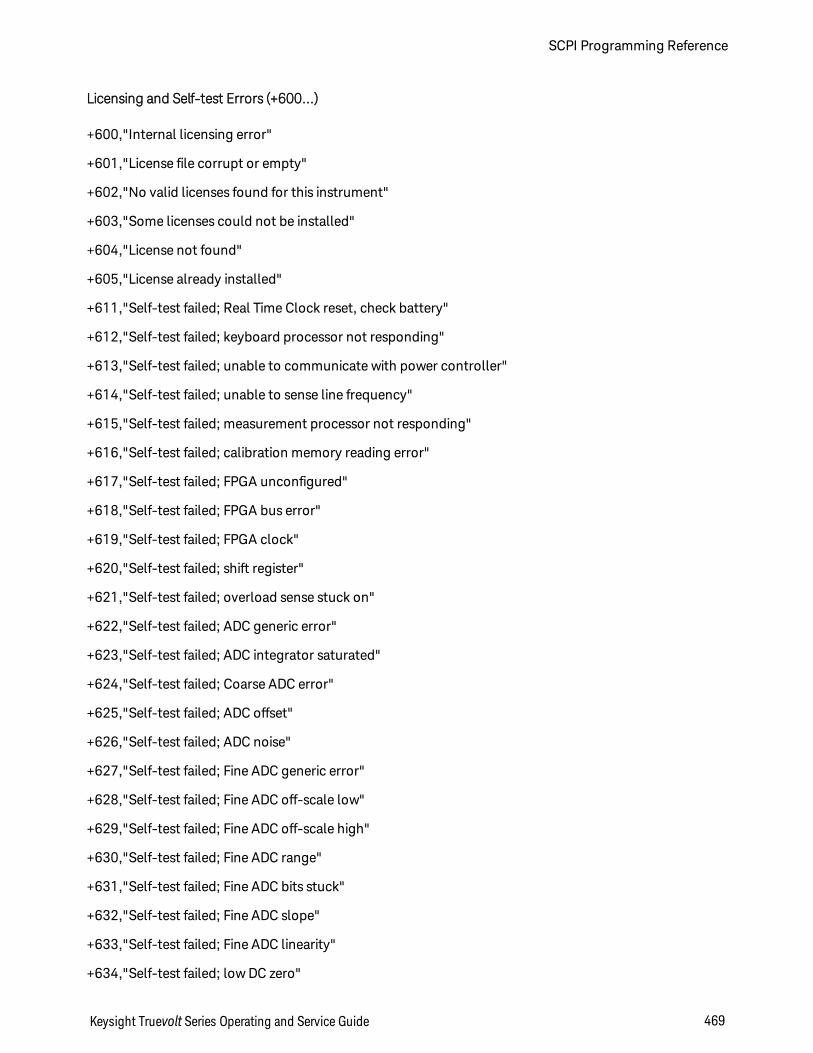
Licensing and Self-test Errors (+600...)
+600,"Internal licensing error"
+601,"License file corrupt or empty"
+602,"No valid licenses found for this instrument"
+603,"Some licenses could not be installed"
+604,"License not found"
+605,"License already installed"
+611,"Self-test failed; Real Time Clock reset, check battery"
+612,"Self-test failed; keyboard processor not responding"
+613,"Self-test failed; unable to communicate with power controller"
+614,"Self-test failed; unable to sense line frequency"
+615,"Self-test failed; measurement processor not responding"
+616,"Self-test failed; calibration memory reading error"
+617,"Self-test failed; FPGA unconfigured"
+618,"Self-test failed; FPGA bus error"
+619,"Self-test failed; FPGA clock"
+620,"Self-test failed; shift register"
+621,"Self-test failed; overload sense stuck on"
+622,"Self-test failed; ADC generic error"
+623,"Self-test failed; ADC integrator saturated"
+624,"Self-test failed; Coarse ADC error"
+625,"Self-test failed; ADC offset"
+626,"Self-test failed; ADC noise"
+627,"Self-test failed; Fine ADC generic error"
+628,"Self-test failed; Fine ADC off-scale low"
+629,"Self-test failed; Fine ADC off-scale high"
+630,"Self-test failed; Fine ADC range"
+631,"Self-test failed; Fine ADC bits stuck"
+632,"Self-test failed; Fine ADC slope"
+633,"Self-test failed; Fine ADC linearity"
+634,"Self-test failed; low DC zero"
Keysight Truevolt Series Operating and Service Guide 469
SCPI Programming Reference
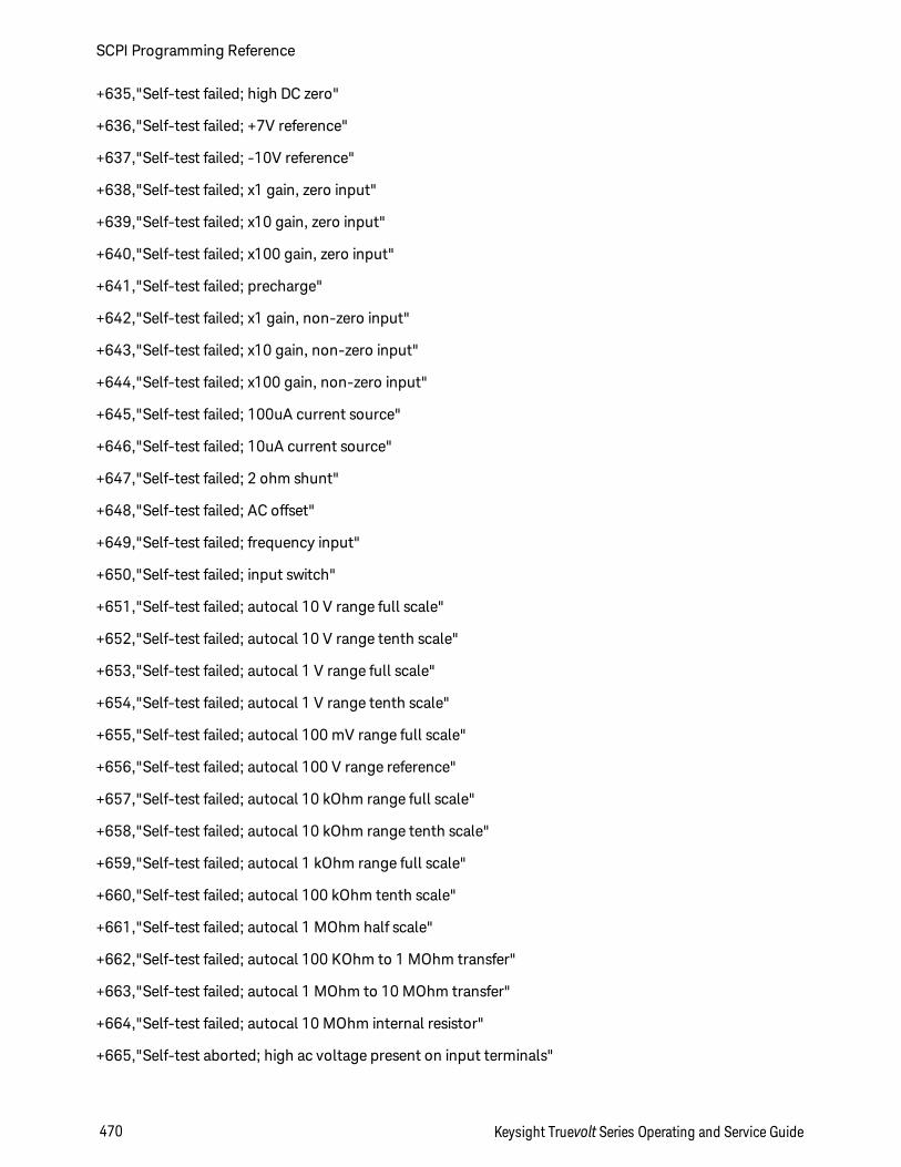
+635,"Self-test failed; high DC zero"
+636,"Self-test failed; +7V reference"
+637,"Self-test failed; -10V reference"
+638,"Self-test failed; x1 gain, zero input"
+639,"Self-test failed; x10 gain, zero input"
+640,"Self-test failed; x100 gain, zero input"
+641,"Self-test failed; precharge"
+642,"Self-test failed; x1 gain, non-zero input"
+643,"Self-test failed; x10 gain, non-zero input"
+644,"Self-test failed; x100 gain, non-zero input"
+645,"Self-test failed; 100uA current source"
+646,"Self-test failed; 10uA current source"
+647,"Self-test failed; 2 ohm shunt"
+648,"Self-test failed; AC offset"
+649,"Self-test failed; frequency input"
+650,"Self-test failed; input switch"
+651,"Self-test failed; autocal 10 V range full scale"
+652,"Self-test failed; autocal 10 V range tenth scale"
+653,"Self-test failed; autocal 1 V range full scale"
+654,"Self-test failed; autocal 1 V range tenth scale"
+655,"Self-test failed; autocal 100 mV range full scale"
+656,"Self-test failed; autocal 100 V range reference"
+657,"Self-test failed; autocal 10 kOhm range full scale"
+658,"Self-test failed; autocal 10 kOhm range tenth scale"
+659,"Self-test failed; autocal 1 kOhm range full scale"
+660,"Self-test failed; autocal 100 kOhm tenth scale"
+661,"Self-test failed; autocal 1 MOhm half scale"
+662,"Self-test failed; autocal 100 KOhm to 1 MOhm transfer"
+663,"Self-test failed; autocal 1 MOhm to 10 MOhm transfer"
+664,"Self-test failed; autocal 10 MOhm internal resistor"
+665,"Self-test aborted; high ac voltage present on input terminals"
SCPI Programming Reference
470 Keysight Truevolt Series Operating and Service Guide
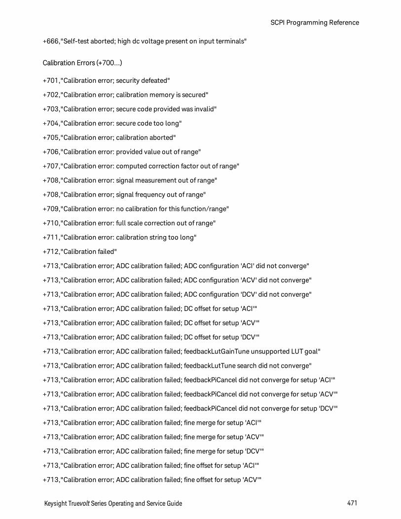
+666,"Self-test aborted; high dc voltage present on input terminals"
Calibration Errors (+700...)
+701,"Calibration error; security defeated"
+702,"Calibration error; calibration memory is secured"
+703,"Calibration error; secure code provided was invalid"
+704,"Calibration error: secure code too long"
+705,"Calibration error; calibration aborted"
+706,"Calibration error: provided value out of range"
+707,"Calibration error: computed correction factor out of range"
+708,"Calibration error: signal measurement out of range"
+708,"Calibration error; signal frequency out of range"
+709,"Calibration error: no calibration for this function/range"
+710,"Calibration error: full scale correction out of range"
+711,"Calibration error: calibration string too long"
+712,"Calibration failed"
+713,"Calibration error; ADC calibration failed; ADC configuration 'ACI' did not converge"
+713,"Calibration error; ADC calibration failed; ADC configuration 'ACV' did not converge"
+713,"Calibration error; ADC calibration failed; ADC configuration 'DCV' did not converge"
+713,"Calibration error; ADC calibration failed; DC offset for setup 'ACI'"
+713,"Calibration error; ADC calibration failed; DC offset for setup 'ACV'"
+713,"Calibration error; ADC calibration failed; DC offset for setup 'DCV'"
+713,"Calibration error; ADC calibration failed; feedbackLutGainTune unsupported LUT goal"
+713,"Calibration error; ADC calibration failed; feedbackLutTune search did not converge"
+713,"Calibration error; ADC calibration failed; feedbackPiCancel did not converge for setup 'ACI'"
+713,"Calibration error; ADC calibration failed; feedbackPiCancel did not converge for setup 'ACV'"
+713,"Calibration error; ADC calibration failed; feedbackPiCancel did not converge for setup 'DCV'"
+713,"Calibration error; ADC calibration failed; fine merge for setup 'ACI'"
+713,"Calibration error; ADC calibration failed; fine merge for setup 'ACV'"
+713,"Calibration error; ADC calibration failed; fine merge for setup 'DCV'"
+713,"Calibration error; ADC calibration failed; fine offset for setup 'ACI'"
+713,"Calibration error; ADC calibration failed; fine offset for setup 'ACV'"
Keysight Truevolt Series Operating and Service Guide 471
SCPI Programming Reference

+713,"Calibration error; ADC calibration failed; fine offset for setup 'DCV'"
+713,"Calibration error; ADC calibration failed; fineDcCancel found non-monotonic value in setup 'ACI'"
+713,"Calibration error; ADC calibration failed; fineDcCancel found non-monotonic value in setup 'ACV'"
+713,"Calibration error; ADC calibration failed; fineDcCancel found non-monotonic value in setup 'DCV'"
+713,"Calibration error; ADC calibration failed; LUT gain for setup 'ACI'"
+713,"Calibration error; ADC calibration failed; LUT gain for setup 'ACV'"
+713,"Calibration error; ADC calibration failed; LUT gain for setup 'DCV'"
+713,"Calibration error; ADC calibration failed; LUT goal incompatible with ACV"
+713,"Calibration error; ADC calibration failed; PI offset for setup 'ACI'"
+713,"Calibration error; ADC calibration failed; PI offset for setup 'ACV'"
+713,"Calibration error; ADC calibration failed; PI offset for setup 'DCV'"
+713,"Calibration error; DCV 10M input impedance gain adjustment out of range"
+715,"Calibration error; must perform +100mV DCV calibration before -100mV"
+715,"Calibration error; must perform +100uA DCI calibration before -100uA"
+715,"Calibration error; must perform +10V DCV calibration before -10V"
+715,"Calibration error; must perform 10MOhm calibration before 100MOhm"
+720,"Calibration error; DCV offset out of range"
+721,"Calibration error; DCI offset out of range"
+722,"Calibration error; RES offset out of range"
+723,"Calibration error; FRES offset out of range"
+724,"Calibration error; extended resistance self cal failed"
+725,"Calibration error; 1000V DC correction out of range"
+726,"Calibration error; ACV offset out of range"
+727,"Calibration error; ACI offset out of range"
+730,"Calibration error; precharge DAC convergence failed"
+731,"Calibration error; A/D turnover correction out of range"
+732,"Calibration error; AC flatness calibration failed"
+733,"Calibration error; AC low frequency correction out of range"
+734,"Calibration error; AC flatness calibration restarted by function/range change"
+735,"Calibration error; 1 kHz AC flatness frequency point must be last frequency point in sequence"
+736,"Calibration error; DCI 100uA range self-cal failed"
SCPI Programming Reference
472 Keysight Truevolt Series Operating and Service Guide
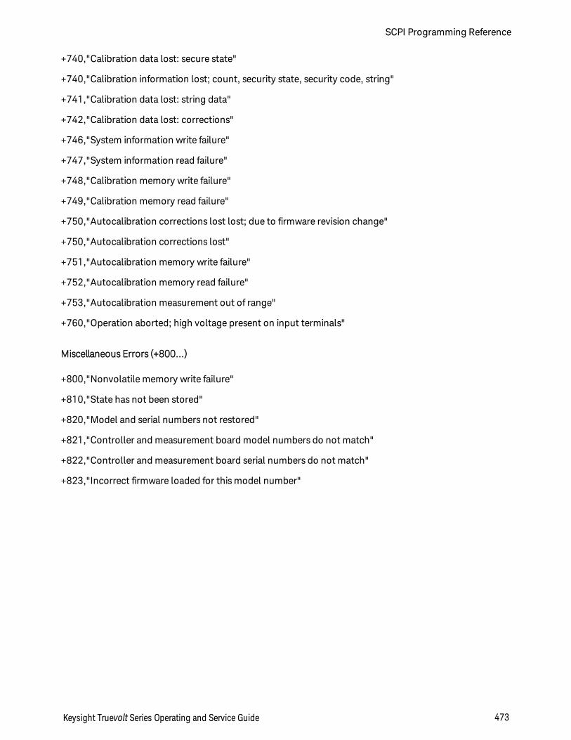
+740,"Calibration data lost: secure state"
+740,"Calibration information lost; count, security state, security code, string"
+741,"Calibration data lost: string data"
+742,"Calibration data lost: corrections"
+746,"System information write failure"
+747,"System information read failure"
+748,"Calibration memory write failure"
+749,"Calibration memory read failure"
+750,"Autocalibration corrections lost lost; due to firmware revision change"
+750,"Autocalibration corrections lost"
+751,"Autocalibration memory write failure"
+752,"Autocalibration memory read failure"
+753,"Autocalibration measurement out of range"
+760,"Operation aborted; high voltage present on input terminals"
Miscellaneous Errors (+800...)
+800,"Nonvolatile memory write failure"
+810,"State has not been stored"
+820,"Model and serial numbers not restored"
+821,"Controller and measurement board model numbers do not match"
+822,"Controller and measurement board serial numbers do not match"
+823,"Incorrect firmware loaded for this model number"
Keysight Truevolt Series Operating and Service Guide 473
SCPI Programming Reference
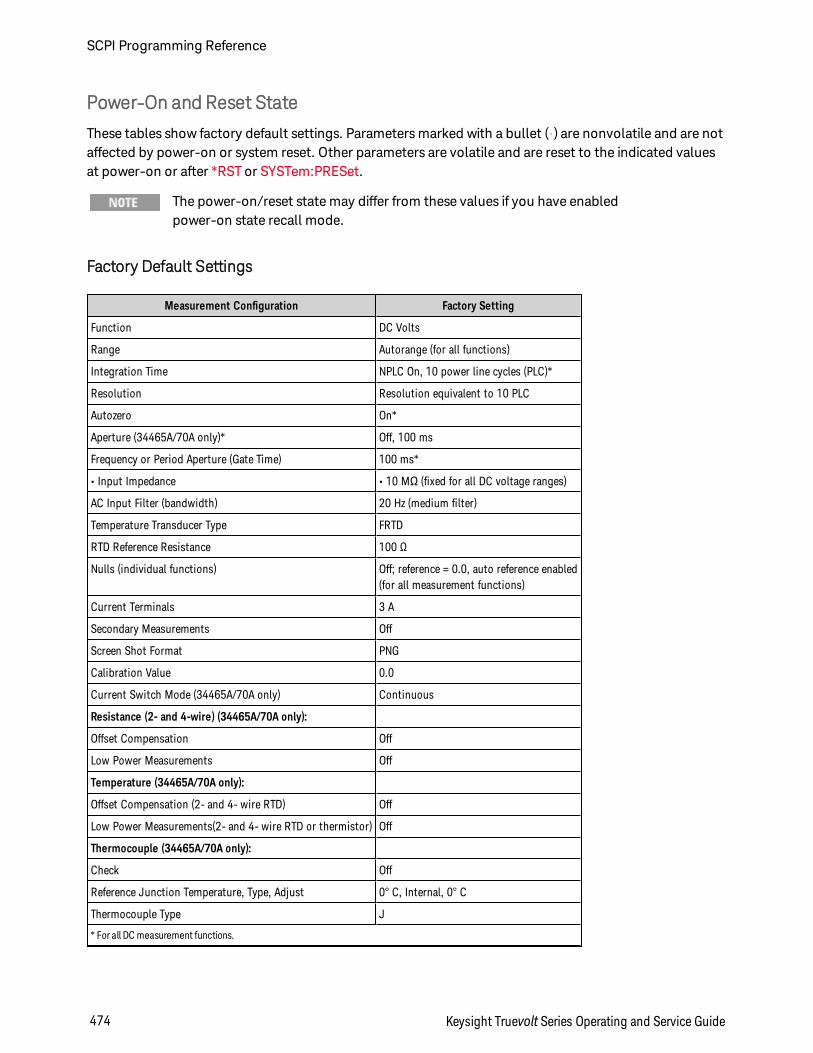
Power-On and Reset State
These tables show factory default settings. Parameters marked with a bullet (•) are nonvolatile and are notaffected by power-on or system reset. Other parameters are volatile and are reset to the indicated valuesat power-on or after *RST or SYSTem:PRESet.
The power-on/reset state may differ from these values if you have enabledpower-on state recall mode.
Factory Default Settings
Measurement Configuration Factory Setting
Function DC Volts
Range Autorange (for all functions)
Integration Time NPLC On, 10 power line cycles (PLC)*
Resolution Resolution equivalent to 10 PLC
Autozero On*
Aperture (34465A/70A only)* Off, 100 ms
Frequency or Period Aperture (Gate Time) 100 ms*
• Input Impedance • 10 MΩ (fixed for all DC voltage ranges)
AC Input Filter (bandwidth) 20 Hz (medium filter)
Temperature Transducer Type FRTD
RTD Reference Resistance 100 Ω
Nulls (individual functions) Off; reference = 0.0, auto reference enabled(for all measurement functions)
Current Terminals 3 A
Secondary Measurements Off
Screen Shot Format PNG
Calibration Value 0.0
Current Switch Mode (34465A/70A only) Continuous
Resistance (2- and 4-wire) (34465A/70A only):
Offset Compensation Off
Low Power Measurements Off
Temperature (34465A/70A only):
Offset Compensation (2- and 4- wire RTD) Off
Low Power Measurements(2- and 4- wire RTD or thermistor) Off
Thermocouple (34465A/70A only):
Check Off
Reference Junction Temperature, Type, Adjust 0° C, Internal, 0° C
Thermocouple Type J
* For all DC measurement functions.
SCPI Programming Reference
474 Keysight Truevolt Series Operating and Service Guide
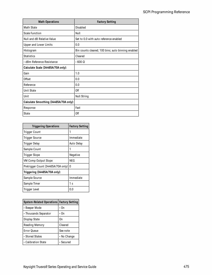
Math Operations Factory Setting
Math State Disabled
Scale Function Null
Null and dB Relative Value Set to 0.0 with auto reference enabled
Upper and Lower Limits 0.0
Histogram Bin counts cleared; 100 bins; auto binning enabled
Statistics Cleared
• dBm Reference Resistance • 600 Ω
Calculate Scale (34465A/70A only):
Gain 1.0
Offset 0.0
Reference 0.0
Unit State Off
Unit Null String
Calculate Smoothing (34465A/70A only):
Response Fast
State Off
Triggering Operations Factory Setting
Trigger Count 1
Trigger Source Immediate
Trigger Delay Auto Delay
Sample Count 1
Trigger Slope Negative
VM Comp Output Slope NEG
Pretrigger Count (34465A/70A only) 0
Triggering (34465A/70A only):
Sample Source Immediate
Sample Timer 1 s
Trigger Level 0.0
System-Related Operations Factory Setting
• Beeper Mode • On
• Thousands Separator • On
Display State On
Reading Memory Cleared
Error Queue See note
• Stored States • No Change
• Calibration State • Secured
Keysight Truevolt Series Operating and Service Guide 475
SCPI Programming Reference
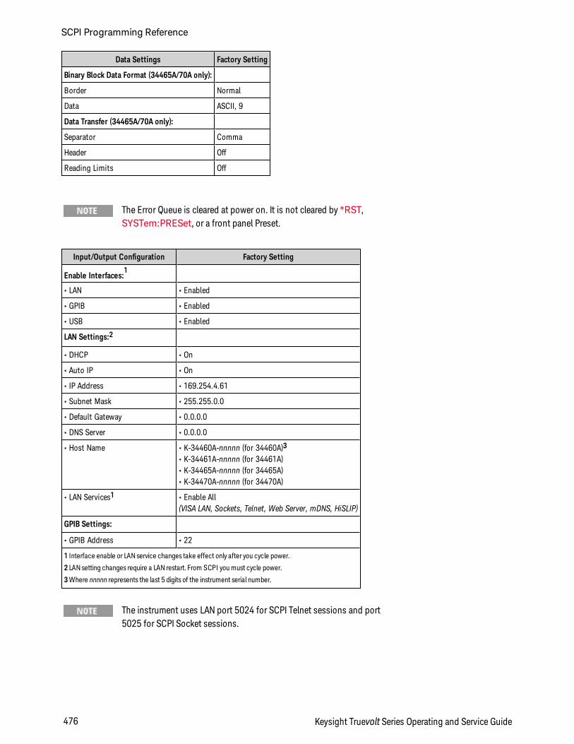
Data Settings Factory Setting
Binary Block Data Format (34465A/70A only):
Border Normal
Data ASCII, 9
Data Transfer (34465A/70A only):
Separator Comma
Header Off
Reading Limits Off
The Error Queue is cleared at power on. It is not cleared by *RST,SYSTem:PRESet, or a front panel Preset.
Input/Output Configuration Factory Setting
Enable Interfaces:1
• LAN • Enabled
• GPIB • Enabled
• USB • Enabled
LAN Settings:2
• DHCP • On
• Auto IP • On
• IP Address • 169.254.4.61
• Subnet Mask • 255.255.0.0
• Default Gateway • 0.0.0.0
• DNS Server • 0.0.0.0
• Host Name • K-34460A-nnnnn (for 34460A)3
• K-34461A-nnnnn (for 34461A)• K-34465A-nnnnn (for 34465A)• K-34470A-nnnnn (for 34470A)
• LAN Services1 • Enable All(VISA LAN, Sockets, Telnet, Web Server, mDNS, HiSLIP)
GPIB Settings:
• GPIB Address • 22
1 Interface enable or LAN service changes take effect only after you cycle power.
2 LAN setting changes require a LAN restart. From SCPI you must cycle power.
3Where nnnnn represents the last 5 digits of the instrument serial number.
The instrument uses LAN port 5024 for SCPI Telnet sessions and port5025 for SCPI Socket sessions.
SCPI Programming Reference
476 Keysight Truevolt Series Operating and Service Guide
Service and RepairThis section contains basic instrument service information.
Types of Service Available
Cleaning
Electrostatic Discharge (ESD) Precautions
Additional service information is found here:
Power Supplies
Troubleshooting
Self-Test Procedures
User Replaceable Parts
Disassembly
Battery Replacement
3 A and 10 A Current Path Fuse Replacement
Installing the Optional GPIB Interface
Types of Service Available
If your instrument fails during the warranty period, Keysight Technologies will repair or replace it underthe terms of your warranty. After your warranty expires, Keysight offers repair services at competitiveprices. You also have the option to purchase a service contract that extends coverage after the standardwarranty expires.
Obtaining Repair Service (Worldwide)
To obtain service for your instrument, contact your nearest Keysight Technologies Service Center. Theywill arrange to have your unit repaired or replaced, and can provide warranty or repair–cost informationwhere applicable. Ask the Keysight Technologies Service Center for shipping instructions, including whatcomponents to ship. Keysight recommends that you retain the original shipping carton for return ship-ments.
Keysight Truevolt Series Operating and Service Guide 477
Service and Repair
Repackaging for Shipment
To ship the unit to Keysight for service or repair:
l Attach a tag to the unit identifying the owner and indicating the required service or repair. Include themodel number and full serial number.
l Place the unit in its original container with appropriate packaging material.
l Secure the container with strong tape or metal bands.
l If the original shipping container is unavailable, use a container that will ensure at least 10 cm (4 in.) ofcompressible packaging material around the entire instrument. Use static-free packaging materials.
Keysight suggests that you always insure shipments.
Cleaning
To prevent electrical shock, disconnect the instrument from AC mains power and disconnect all test leadsbefore cleaning. Clean the outside of the instrument using a soft, lint-free, cloth slightly dampened withwater.
Do not use detergent or solvents.
Do not attempt to clean internally.
If needed, contact a Keysight Technologies Sales and Service office to arrange for proper cleaning toensure that safety features and performance are maintained.
Electrostatic Discharge (ESD) Precautions
Almost all electrical components can be damaged by electrostatic discharge (ESD) during handling. Com-ponent damage can occur at electrostatic discharge voltages as low as 50 V.
The following guidelines will help prevent ESD damage during service operations:
l Disassemble instruments only in a static-free work area.
l Use a conductive work area to reduce static charges.
l Use a conductive wrist strap to reduce static charge accumulation.
l Minimize handling.
l Keep replacement parts in original static-free packaging.
l Remove all plastic, foam, vinyl, paper, and other static-generating materials from the immediate workarea.
Service and Repair
478 Keysight Truevolt Series Operating and Service Guide
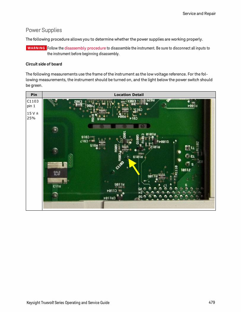
Power Supplies
The following procedure allows you to determine whether the power supplies are working properly.
Follow the disassembly procedure to disassemble the instrument. Be sure to disconnect all inputs tothe instrument before beginning disassembly.
Circuit side of board
The following measurements use the frame of the instrument as the low voltage reference. For the fol-lowing measurements, the instrument should be turned on, and the light below the power switch shouldbe green.
Pin Location Detail
C1103pin 1
15 V ±25%
Keysight Truevolt Series Operating and Service Guide 479
Service and Repair
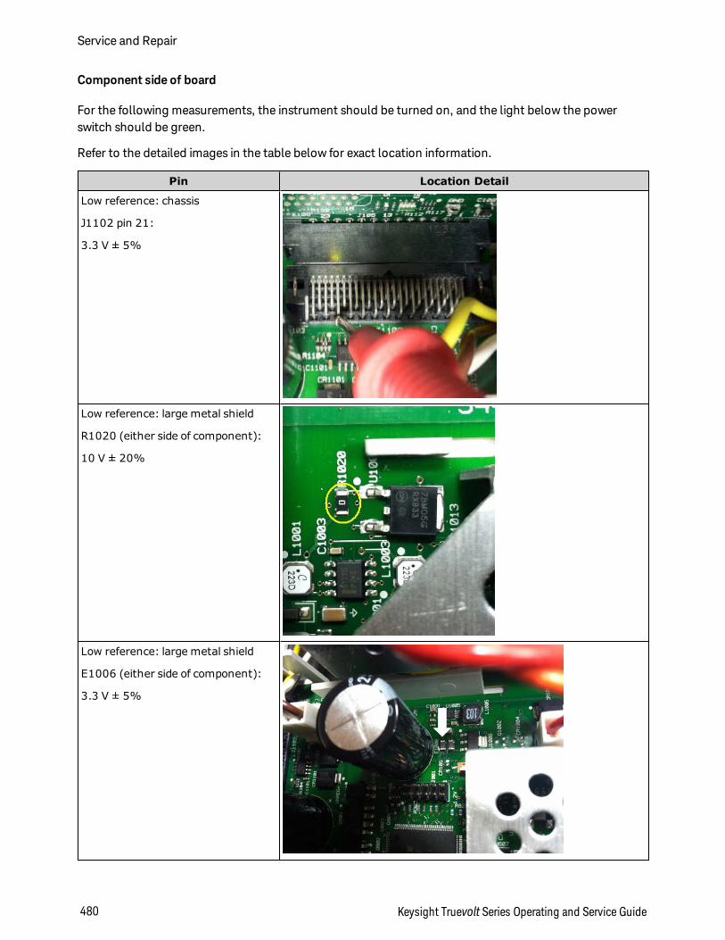
Component side of board
For the following measurements, the instrument should be turned on, and the light below the powerswitch should be green.
Refer to the detailed images in the table below for exact location information.
Pin Location Detail
Low reference: chassis
J1102 pin 21:
3.3 V ± 5%
Low reference: large metal shield
R1020 (either side of component):
10 V ± 20%
Low reference: large metal shield
E1006 (either side of component):
3.3 V ± 5%
Service and Repair
480 Keysight Truevolt Series Operating and Service Guide
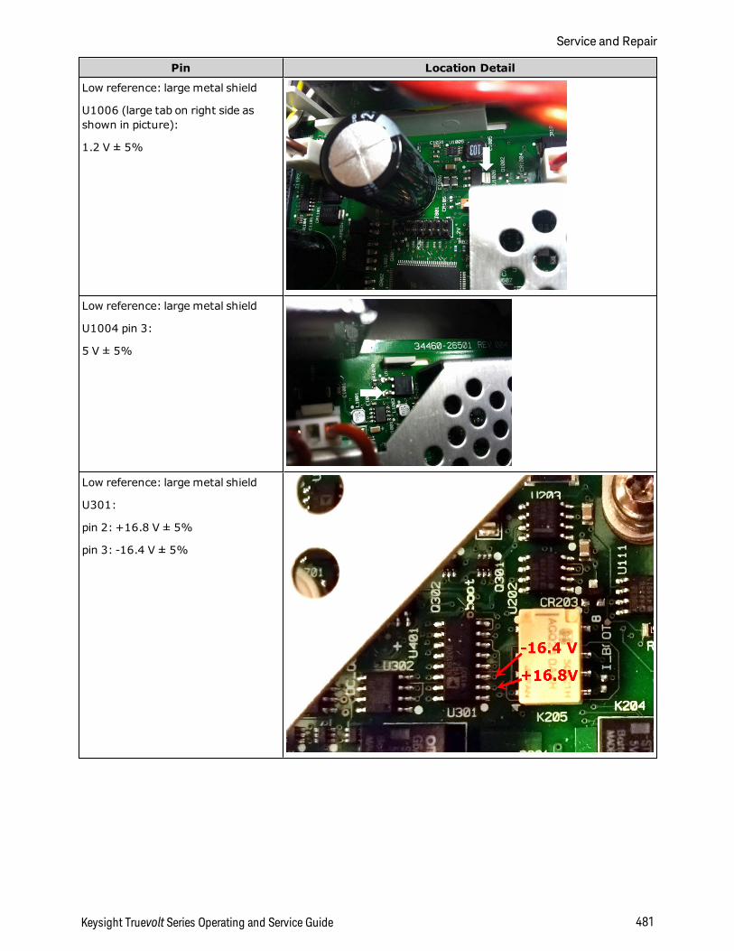
Pin Location Detail
Low reference: large metal shield
U1006 (large tab on right side asshown in picture):
1.2 V ± 5%
Low reference: large metal shield
U1004 pin 3:
5 V ± 5%
Low reference: large metal shield
U301:
pin 2: +16.8 V ± 5%
pin 3: -16.4 V ± 5%
Keysight Truevolt Series Operating and Service Guide 481
Service and Repair
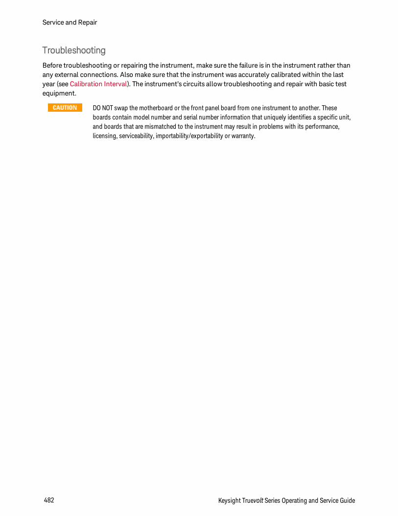
Troubleshooting
Before troubleshooting or repairing the instrument, make sure the failure is in the instrument rather thanany external connections. Also make sure that the instrument was accurately calibrated within the lastyear (see Calibration Interval). The instrument’s circuits allow troubleshooting and repair with basic testequipment.
DO NOT swap the motherboard or the front panel board from one instrument to another. Theseboards contain model number and serial number information that uniquely identifies a specific unit,and boards that are mismatched to the instrument may result in problems with its performance,licensing, serviceability, importability/exportability or warranty.
Service and Repair
482 Keysight Truevolt Series Operating and Service Guide
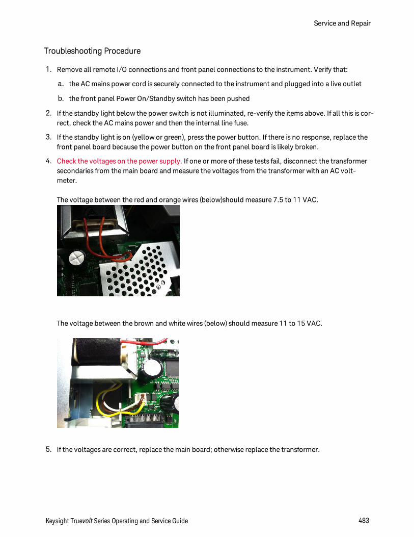
Troubleshooting Procedure
1. Remove all remote I/O connections and front panel connections to the instrument. Verify that:
a. the AC mains power cord is securely connected to the instrument and plugged into a live outlet
b. the front panel Power On/Standby switch has been pushed
2. If the standby light below the power switch is not illuminated, re-verify the items above. If all this is cor-rect, check the AC mains power and then the internal line fuse.
3. If the standby light is on (yellow or green), press the power button. If there is no response, replace thefront panel board because the power button on the front panel board is likely broken.
4. Check the voltages on the power supply. If one or more of these tests fail, disconnect the transformersecondaries from the main board and measure the voltages from the transformer with an AC volt-meter.
The voltage between the red and orange wires (below)should measure 7.5 to 11 VAC.
The voltage between the brown and white wires (below) should measure 11 to 15 VAC.
5. If the voltages are correct, replace the main board; otherwise replace the transformer.
Keysight Truevolt Series Operating and Service Guide 483
Service and Repair
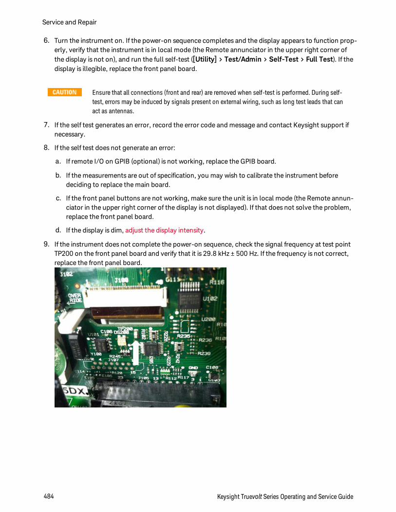
6. Turn the instrument on. If the power-on sequence completes and the display appears to function prop-erly, verify that the instrument is in local mode (the Remote annunciator in the upper right corner ofthe display is not on), and run the full self-test ([Utility] > Test/Admin > Self-Test > Full Test). If thedisplay is illegible, replace the front panel board.
Ensure that all connections (front and rear) are removed when self-test is performed. During self-test, errors may be induced by signals present on external wiring, such as long test leads that canact as antennas.
7. If the self test generates an error, record the error code and message and contact Keysight support ifnecessary.
8. If the self test does not generate an error:
a. If remote I/O on GPIB (optional) is not working, replace the GPIB board.
b. If the measurements are out of specification, you may wish to calibrate the instrument beforedeciding to replace the main board.
c. If the front panel buttons are not working, make sure the unit is in local mode (the Remote annun-ciator in the upper right corner of the display is not displayed). If that does not solve the problem,replace the front panel board.
d. If the display is dim, adjust the display intensity.
9. If the instrument does not complete the power-on sequence, check the signal frequency at test pointTP200 on the front panel board and verify that it is 29.8 kHz ± 500 Hz. If the frequency is not correct,replace the front panel board.
Service and Repair
484 Keysight Truevolt Series Operating and Service Guide
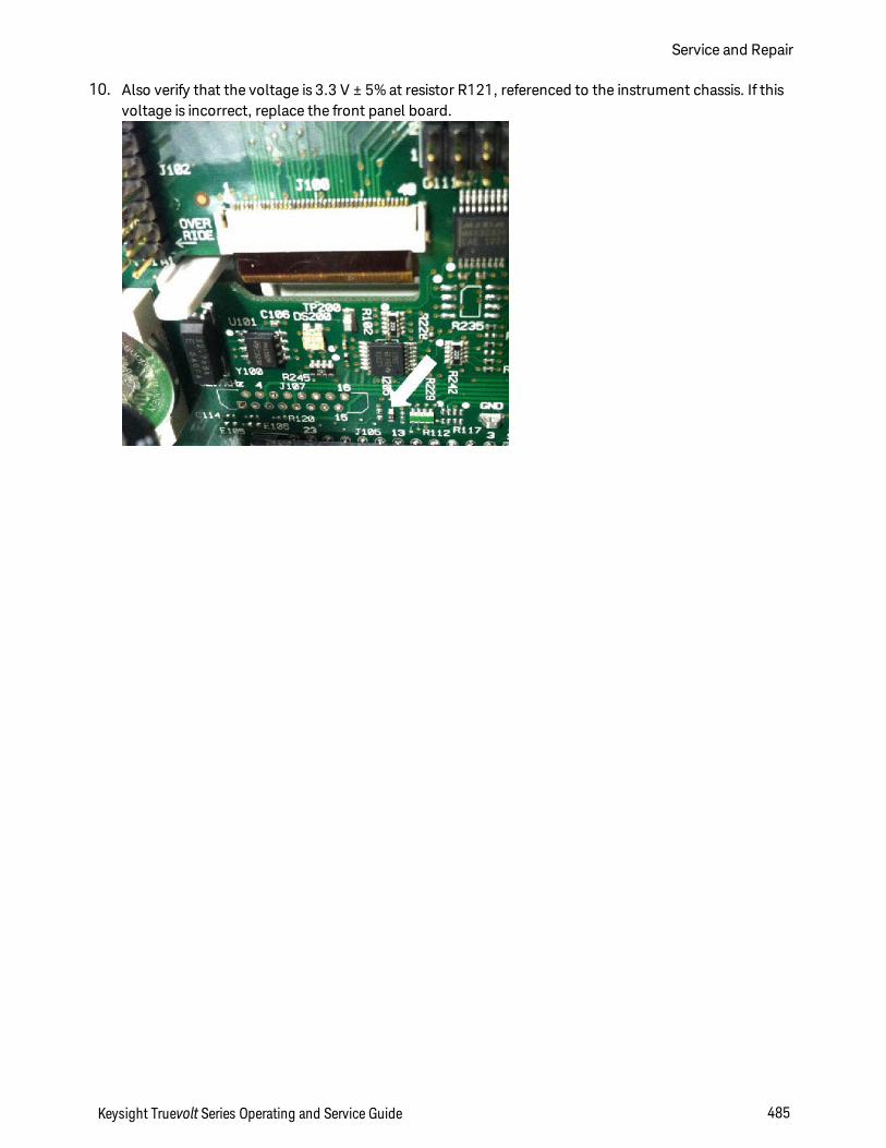
10. Also verify that the voltage is 3.3 V ± 5% at resistor R121, referenced to the instrument chassis. If thisvoltage is incorrect, replace the front panel board.
Keysight Truevolt Series Operating and Service Guide 485
Service and Repair
Self-Test Procedures
Power-On Self-Test
Each time the instrument is powered on, it performs a self-test on its real-time clock, keyboard processor,power controller, measurement processor, calibration memory, FPGA, ADC, gain and offset circuitry, andvoltage references. This self-test is equivalent to the *TST? SCPI query, and you do not need to removeinputs to the instrument to run the test.
Full Self-Test
A complete self-test (TEST:ALL?) takes approximately two seconds. This tests all of the items tested by thepower-on self-test and includes further tests for gain, current source, and shunt circuitry.
When self-test completes, either "Self-test Passed" or "Self-test Failed" appears on front panel.
Execute the complete self-test before performing any verification or calibration procedures.
You must remove all input connections to the instrument before running the full self-test.
Remote I/O Execution
1. Connect to the instrument using the remote interface (Remote Interface Configuration).
2. Send *TST? or TEST:ALL? and read the result: pass (+0) or fail (+1). Use SYSTem:ERRor? to view errors.See the list of self-test errors for details.
Front Panel Execution
1. Press [Shift] > [Utility] > Test/Admin > Self Test.
2. View any failures by pressing [Shift] > [Help] > View remote command error queue.
Service and Repair
486 Keysight Truevolt Series Operating and Service Guide
User Replaceable Parts
Replacement parts for the instrument are listed below. Unless otherwise shown, all parts apply to allTruevoltmodels.
Part Number Description
34401-86020 Bumper Kit
33220-88304 Rear Bezel
34401-45021 Handle
33220-84101 Cover
5041-5228 Keypad
2090-1051 Display
2110-0817 Line Fuse (250 mA, 250 V, time delay)
2110-1547 Current Protection Fuse (3.15 A, 500 VAC/ 400 VDC, time delay)
2110-1402 Internal Fuse (11 A, 1000 V, fast acting)
34460-87910 Transformer
34401-45012 Terminal Latch
5041-5238 Power Module
34460-40201 Plastic Front Panel (34460A)
34461-40201 Plastic Front Panel (34461A)
34465-40201 Plastic Front Panel (34465A)
34470-40201 Plastic Front Panel (34470A)
53200-49311 Window
5041-5231 Front Panel Shield
5041-5225 Front/Rear Push Rod (34461A, 34465A, 34470A)
5041-5232 Fan (34461A, 34465A, 34470A)
5041-5261 Fan Shield (34465A, 34470A)
5041-5257 Cable Assembly, Thermistor (34465A, 34470A)
1420-0356 Battery (in front panel)
34470-66303 Reference Assembly
Keysight Truevolt Series Operating and Service Guide 487
Service and Repair
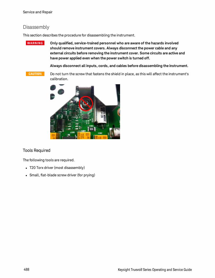
Disassembly
This section describes the procedure for disassembling the instrument.
Only qualified, service-trained personnel who are aware of the hazards involvedshould remove instrument covers. Always disconnect the power cable and anyexternal circuits before removing the instrument cover. Some circuits are active andhave power applied even when the power switch is turned off.
Always disconnect all inputs, cords, and cables before disassembling the instrument.
Do not turn the screw that fastens the shield in place, as this will affect the instrument'scalibration.
Tools Required
The following tools are required.
l T20 Torx driver (most disassembly)
l Small, flat-blade screw driver (for prying)
Service and Repair
488 Keysight Truevolt Series Operating and Service Guide
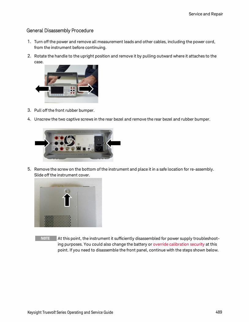
General Disassembly Procedure
1. Turn off the power and remove all measurement leads and other cables, including the power cord,from the instrument before continuing.
2. Rotate the handle to the upright position and remove it by pulling outward where it attaches to thecase.
3. Pull off the front rubber bumper.
4. Unscrew the two captive screws in the rear bezel and remove the rear bezel and rubber bumper.
5. Remove the screw on the bottom of the instrument and place it in a safe location for re-assembly.Slide off the instrument cover.
At this point, the instrument it sufficiently disassembled for power supply troubleshoot-ing purposes. You could also change the battery or override calibration security at thispoint. If you need to disassemble the front panel, continue with the steps shown below.
Keysight Truevolt Series Operating and Service Guide 489
Service and Repair
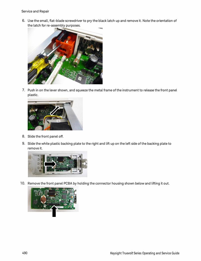
6. Use the small, flat-blade screwdriver to pry the black latch up and remove it. Note the orientation ofthe latch for re-assembly purposes.
7. Push in on the lever shown, and squeeze the metal frame of the instrument to release the front panelplastic.
8. Slide the front panel off.
9. Slide the white plastic backing plate to the right and lift up on the left side of the backing plate toremove it.
10. Remove the front panel PCBA by holding the connector housing shown below and lifting it out.
Service and Repair
490 Keysight Truevolt Series Operating and Service Guide
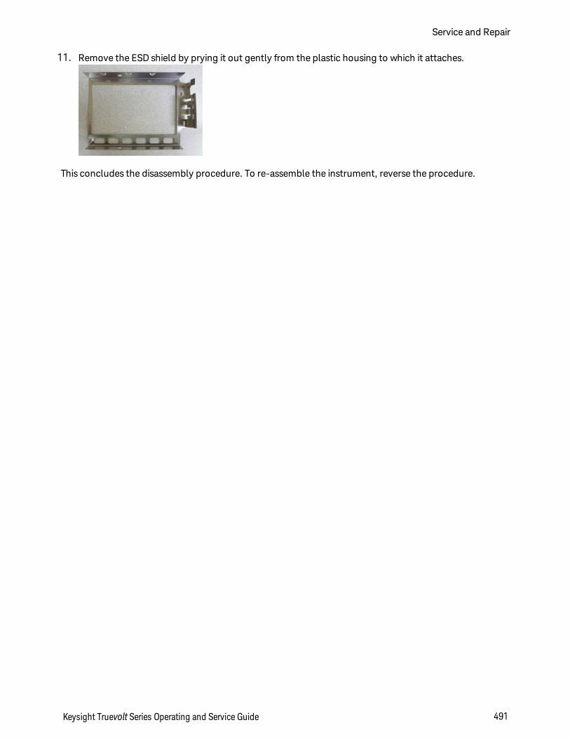
11. Remove the ESD shield by prying it out gently from the plastic housing to which it attaches.
This concludes the disassembly procedure. To re-assemble the instrument, reverse the procedure.
Keysight Truevolt Series Operating and Service Guide 491
Service and Repair
Battery Replacement
This section describes the procedure for replacing the battery on the instrument's front panel.
Only qualified, service-trained personnel who are aware of the hazards involvedshould remove instrument covers. Always disconnect the power cable and anyexternal circuits before removing the instrument cover. Some circuits are active andhave power applied even when the power switch is turned off.
Always disconnect all inputs, cords, and cables before disassembling the instrument.
Tools Required
l T20 Torx driver (most disassembly)
l Small, flat-blade screw driver (for prying)
Service and Repair
492 Keysight Truevolt Series Operating and Service Guide
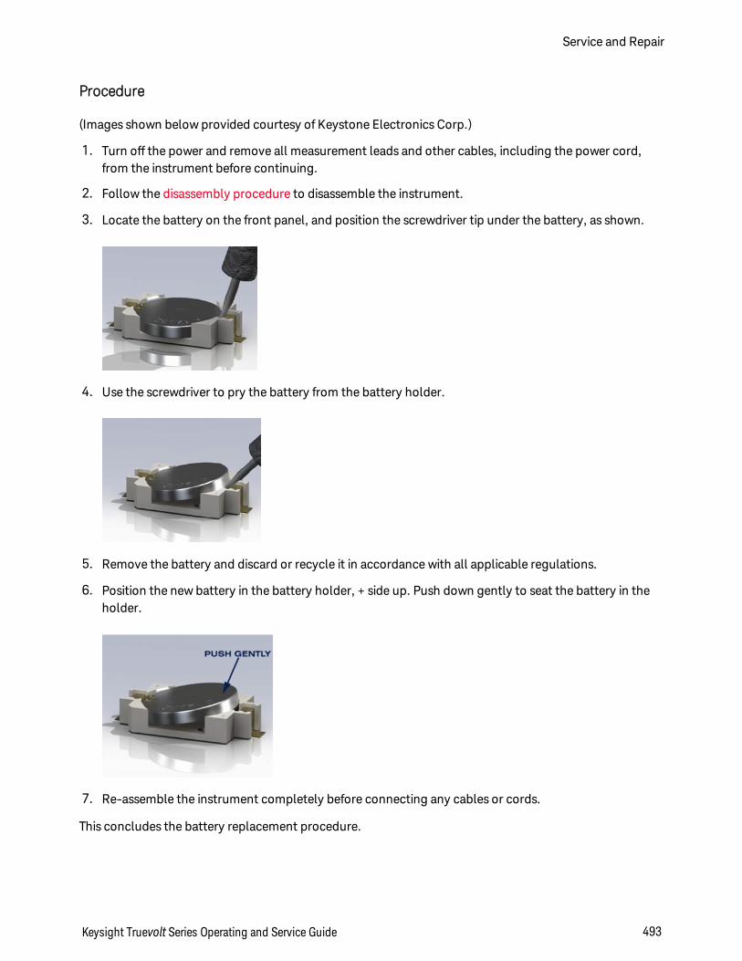
Procedure
(Images shown below provided courtesy of Keystone Electronics Corp.)
1. Turn off the power and remove all measurement leads and other cables, including the power cord,from the instrument before continuing.
2. Follow the disassembly procedure to disassemble the instrument.
3. Locate the battery on the front panel, and position the screwdriver tip under the battery, as shown.
4. Use the screwdriver to pry the battery from the battery holder.
5. Remove the battery and discard or recycle it in accordance with all applicable regulations.
6. Position the new battery in the battery holder, + side up. Push down gently to seat the battery in theholder.
7. Re-assemble the instrument completely before connecting any cables or cords.
This concludes the battery replacement procedure.
Keysight Truevolt Series Operating and Service Guide 493
Service and Repair
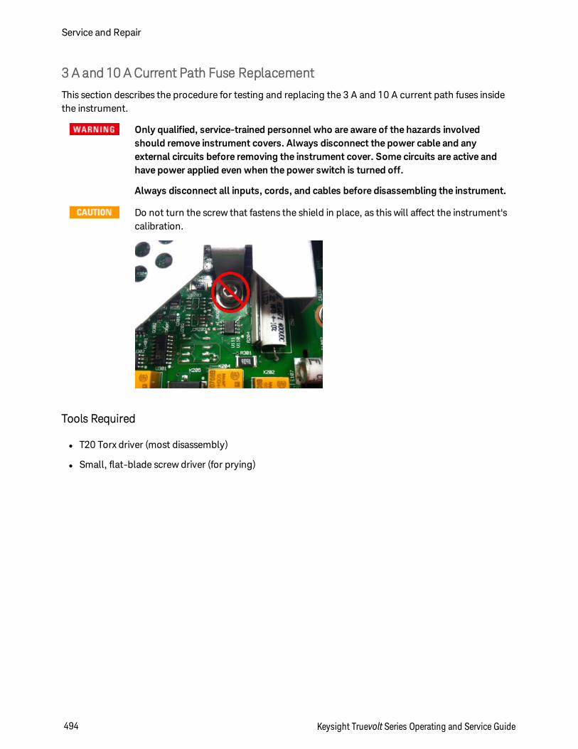
3 A and 10 A Current Path Fuse Replacement
This section describes the procedure for testing and replacing the 3 A and 10 A current path fuses insidethe instrument.
Only qualified, service-trained personnel who are aware of the hazards involvedshould remove instrument covers. Always disconnect the power cable and anyexternal circuits before removing the instrument cover. Some circuits are active andhave power applied even when the power switch is turned off.
Always disconnect all inputs, cords, and cables before disassembling the instrument.
Do not turn the screw that fastens the shield in place, as this will affect the instrument'scalibration.
Tools Required
l T20 Torx driver (most disassembly)
l Small, flat-blade screw driver (for prying)
Service and Repair
494 Keysight Truevolt Series Operating and Service Guide
Testing the Fuses
3 A Current Path
To determine whether the instrument's 3 A current path has a fuse that must be replaced, press [Cont] toput the DMM in continuity measurement mode, and short the HI Input terminal to the 3 A current ter-minal. If the measurement displays OPEN, one of the two fuses must be replaced. One fuse is accessiblefrom the instrument's rear panel; the other is internal.
If the 3 A current path has a bad fuse, it is very likely to be the fuse accessible from the lower left corner ofthe instrument's rear panel (part number 2110-1547, 3.15 A, 500 VAC/400 VDC, time delay). Simply usea flat-blade screw driver to turn the fuse holder counter-clockwise and access the fuse. Put the new fuseinto the fuse holder and insert the assembly back into the instrument, turning the fuse holder clockwise tolock it in place.
If the 3 A path still has a bad fuse, replace the internal 3 A current path fuse as described below.
10 A Current Path (34461A/65A/70A only)
To determine whether the instrument's 10 A current path has a fuse that must be replaced, press [Cont] toput the DMM in continuity measurement mode, and short the HI Input terminal to the 10 A current ter-minal. If the measurement displays OPEN, replace the internal 10 A current path fuse as described below.
Keysight Truevolt Series Operating and Service Guide 495
Service and Repair
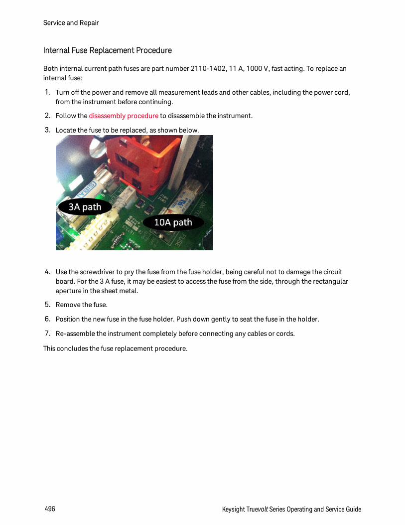
Internal Fuse Replacement Procedure
Both internal current path fuses are part number 2110-1402, 11 A, 1000 V, fast acting. To replace aninternal fuse:
1. Turn off the power and remove all measurement leads and other cables, including the power cord,from the instrument before continuing.
2. Follow the disassembly procedure to disassemble the instrument.
3. Locate the fuse to be replaced, as shown below.
4. Use the screwdriver to pry the fuse from the fuse holder, being careful not to damage the circuitboard. For the 3 A fuse, it may be easiest to access the fuse from the side, through the rectangularaperture in the sheet metal.
5. Remove the fuse.
6. Position the new fuse in the fuse holder. Push down gently to seat the fuse in the holder.
7. Re-assemble the instrument completely before connecting any cables or cords.
This concludes the fuse replacement procedure.
Service and Repair
496 Keysight Truevolt Series Operating and Service Guide
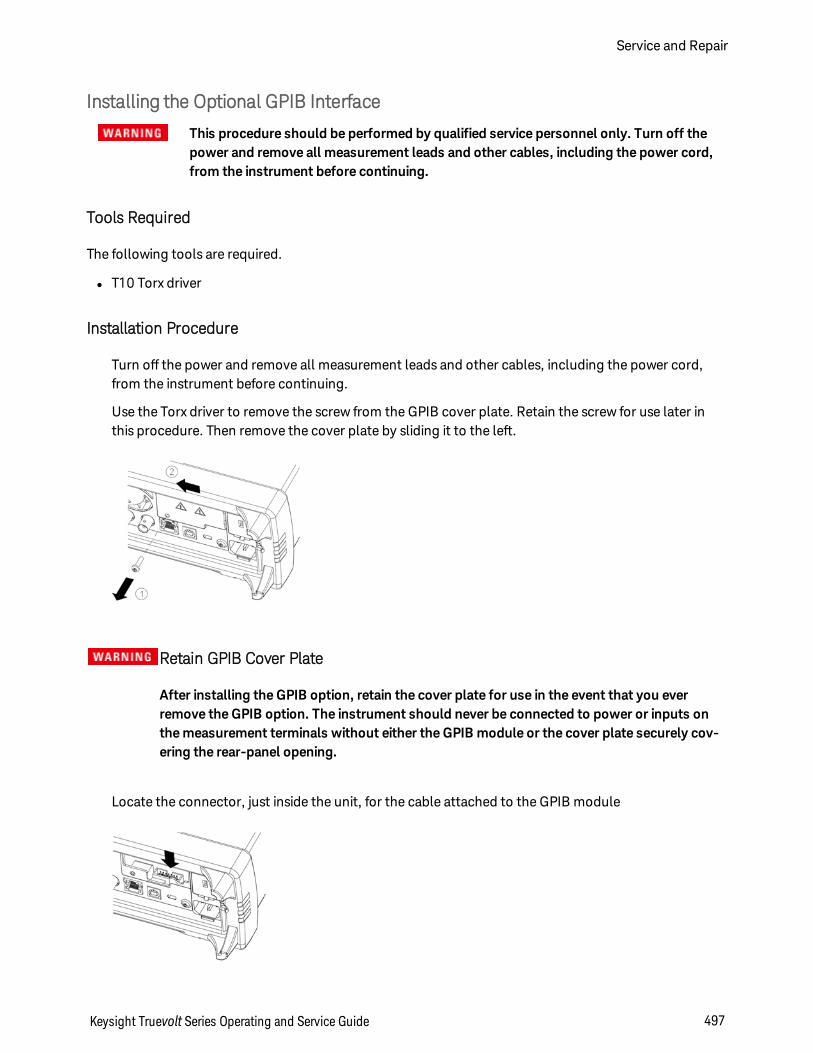
Installing the Optional GPIB Interface
This procedure should be performed by qualified service personnel only. Turn off thepower and remove all measurement leads and other cables, including the power cord,from the instrument before continuing.
Tools Required
The following tools are required.
l T10 Torx driver
Installation Procedure
Turn off the power and remove all measurement leads and other cables, including the power cord,from the instrument before continuing.
Use the Torx driver to remove the screw from the GPIB cover plate. Retain the screw for use later inthis procedure. Then remove the cover plate by sliding it to the left.
Retain GPIB Cover Plate
After installing the GPIB option, retain the cover plate for use in the event that you everremove the GPIB option. The instrument should never be connected to power or inputs onthe measurement terminals without either the GPIB module or the cover plate securely cov-ering the rear-panel opening.
Locate the connector, just inside the unit, for the cable attached to the GPIB module
Keysight Truevolt Series Operating and Service Guide 497
Service and Repair
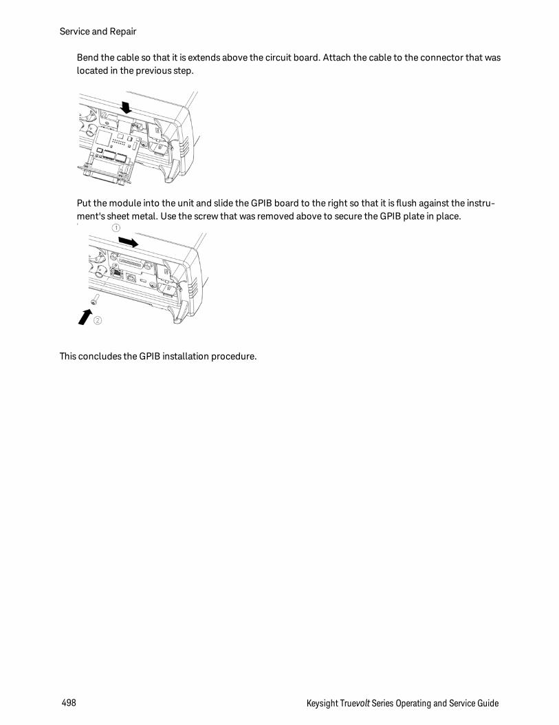
Bend the cable so that it is extends above the circuit board. Attach the cable to the connector that waslocated in the previous step.
Put the module into the unit and slide the GPIB board to the right so that it is flush against the instru-ment's sheet metal. Use the screw that was removed above to secure the GPIB plate in place.
This concludes the GPIB installation procedure.
Service and Repair
498 Keysight Truevolt Series Operating and Service Guide
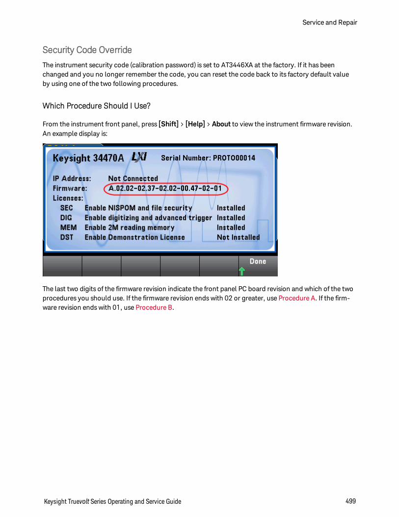
Security Code Override
The instrument security code (calibration password) is set to AT3446XA at the factory. If it has beenchanged and you no longer remember the code, you can reset the code back to its factory default valueby using one of the two following procedures.
Which Procedure Should I Use?
From the instrument front panel, press [Shift] > [Help] > About to view the instrument firmware revision.An example display is:
The last two digits of the firmware revision indicate the front panel PC board revision and which of the twoprocedures you should use. If the firmware revision ends with 02 or greater, use Procedure A. If the firm-ware revision ends with 01, use Procedure B.
Keysight Truevolt Series Operating and Service Guide 499
Service and Repair
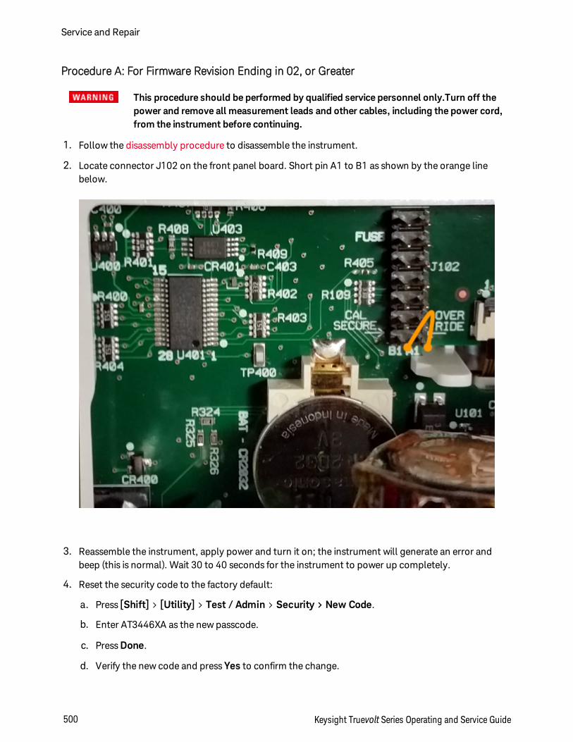
Procedure A: For Firmware Revision Ending in 02, or Greater
This procedure should be performed by qualified service personnel only.Turn off thepower and remove all measurement leads and other cables, including the power cord,from the instrument before continuing.
1. Follow the disassembly procedure to disassemble the instrument.
2. Locate connector J102 on the front panel board. Short pin A1 to B1 as shown by the orange linebelow.
3. Reassemble the instrument, apply power and turn it on; the instrument will generate an error andbeep (this is normal). Wait 30 to 40 seconds for the instrument to power up completely.
4. Reset the security code to the factory default:
a. Press [Shift] > [Utility] > Test / Admin > Security > New Code.
b. Enter AT3446XA as the new passcode.
c. Press Done.
d. Verify the new code and press Yes to confirm the change.
Service and Repair
500 Keysight Truevolt Series Operating and Service Guide

5. Remove power, disassemble the instrument, and remove the short. Then reassemble the instrumentto complete the security code (calibration password) reset procedure.
Keysight Truevolt Series Operating and Service Guide 501
Service and Repair
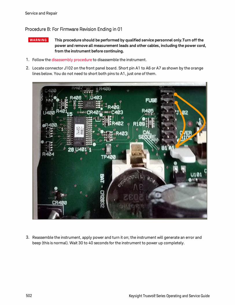
Procedure B: For Firmware Revision Ending in 01
This procedure should be performed by qualified service personnel only.Turn off thepower and remove all measurement leads and other cables, including the power cord,from the instrument before continuing.
1. Follow the disassembly procedure to disassemble the instrument.
2. Locate connector J102 on the front panel board. Short pin A1 to A6 or A7 as shown by the orangelines below. You do not need to short both pins to A1, just one of them.
3. Reassemble the instrument, apply power and turn it on; the instrument will generate an error andbeep (this is normal). Wait 30 to 40 seconds for the instrument to power up completely.
Service and Repair
502 Keysight Truevolt Series Operating and Service Guide
4. Reset the security code to the factory default:
a. Press [Shift] > [Utility] > Test / Admin > Security > New Code.
b. Enter AT3446XA as the new passcode.
c. Press Done.
d. Verify the new code and press Yes to confirm the change.
5. Remove power, disassemble the instrument, and remove the short. Then reassemble the instrumentto complete the security code (calibration password) reset procedure.
Performance VerificationUse the performance verification tests in this section to verify the measurement performance of the instru-ment using the instrument’s specifications listed in the product data sheet.
You can perform three different levels of performance verification tests:
l Self–Test (two types): Internal verification tests that give a high confidence that the instrument isoperational, as described here.
l Quick Verification: A combination of the internal self–tests and selected verification tests.
l Performance Verification Tests: An extensive set of tests that are recommended as an acceptancetest when you first receive the instrument or after performing calibration:
l Zero Offset Verification
l DC Volts and DC Current Gain Verification
l Frequency Accuracy Verification
l AC Voltage and AC Current Verification
l High Current Verification
l Capacitance Verification (Optional Verification Test)
Keysight Truevolt Series Operating and Service Guide 503
Performance Verification
Quick Performance Check
The quick performance check is a combination of internal self–test and an abbreviated performance test(specified by the letter Q in the performance verification tests). This provides a simple method to achievehigh confidence in the instrument’s ability to functionally operate and meet specifications. These tests rep-resent the absolute minimum set of performance checks recommended following any service activity.Auditing the instrument’s performance for the quick check points (designated by a Q) verifies performancefor "normal" accuracy drift mechanisms. This test does not check for abnormal component failures.
To perform the quick performance check, do the following:
l Perform a self–test.
l Perform only the performance verification tests indicated with the letter Q.
If the instrument fails the quick performance check, calibration or repair is required.
The Quick Performance Check can be limited by the factors described in the following section (Per-formance Verification Tests).
Performance Verification
504 Keysight Truevolt Series Operating and Service Guide
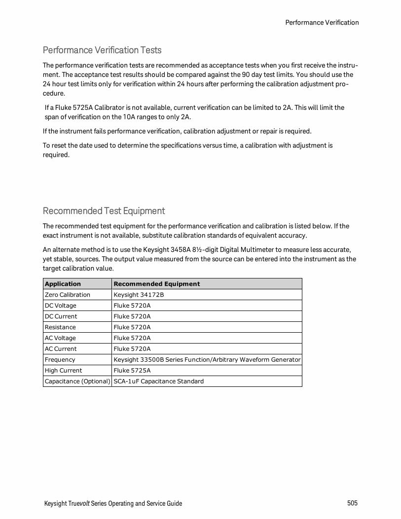
Performance Verification Tests
The performance verification tests are recommended as acceptance tests when you first receive the instru-ment. The acceptance test results should be compared against the 90 day test limits. You should use the24 hour test limits only for verification within 24 hours after performing the calibration adjustment pro-cedure.
If a Fluke 5725A Calibrator is not available, current verification can be limited to 2A. This will limit thespan of verification on the 10A ranges to only 2A.
If the instrument fails performance verification, calibration adjustment or repair is required.
To reset the date used to determine the specifications versus time, a calibration with adjustment isrequired.
Recommended Test Equipment
The recommended test equipment for the performance verification and calibration is listed below. If theexact instrument is not available, substitute calibration standards of equivalent accuracy.
An alternate method is to use the Keysight 3458A 8½-digit Digital Multimeter to measure less accurate,yet stable, sources. The output value measured from the source can be entered into the instrument as thetarget calibration value.
Application Recommended Equipment
Zero Calibration Keysight 34172B
DC Voltage Fluke 5720A
DC Current Fluke 5720A
Resistance Fluke 5720A
AC Voltage Fluke 5720A
AC Current Fluke 5720A
Frequency Keysight 33500B Series Function/Arbitrary Waveform Generator
High Current Fluke 5725A
Capacitance (Optional) SCA-1uF Capacitance Standard
Keysight Truevolt Series Operating and Service Guide 505
Performance Verification
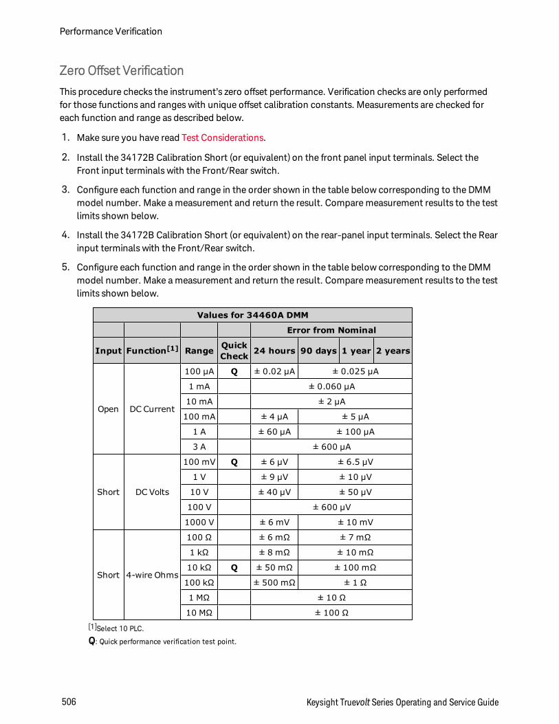
Zero Offset Verification
This procedure checks the instrument’s zero offset performance. Verification checks are only performedfor those functions and ranges with unique offset calibration constants. Measurements are checked foreach function and range as described below.
1. Make sure you have read Test Considerations.
2. Install the 34172B Calibration Short (or equivalent) on the front panel input terminals. Select theFront input terminals with the Front/Rear switch.
3. Configure each function and range in the order shown in the table below corresponding to the DMMmodel number. Make a measurement and return the result. Compare measurement results to the testlimits shown below.
4. Install the 34172B Calibration Short (or equivalent) on the rear-panel input terminals. Select the Rearinput terminals with the Front/Rear switch.
5. Configure each function and range in the order shown in the table below corresponding to the DMMmodel number. Make a measurement and return the result. Compare measurement results to the testlimits shown below.
Values for 34460A DMM
Error from Nominal
Input Function[1] Range QuickCheck 24 hours 90 days 1 year 2 years
Open DC Current
100 µA Q ± 0.02 µA ± 0.025 µA
1 mA ± 0.060 µA
10 mA ± 2 µA
100 mA ± 4 µA ± 5 µA
1 A ± 60 µA ± 100 µA
3 A ± 600 µA
Short DC Volts
100 mV Q ± 6 µV ± 6.5 µV
1 V ± 9 µV ± 10 µV
10 V ± 40 µV ± 50 µV
100 V ± 600 µV
1000 V ± 6 mV ± 10 mV
Short 4-wire Ohms
100 Ω ± 6 mΩ ± 7 mΩ
1 kΩ ± 8 mΩ ± 10 mΩ
10 kΩ Q ± 50 mΩ ± 100 mΩ
100 kΩ ± 500 mΩ ± 1 Ω
1 MΩ ± 10 Ω
10 MΩ ± 100 Ω[1]Select 10 PLC.
Q: Quick performance verification test point.
Performance Verification
506 Keysight Truevolt Series Operating and Service Guide
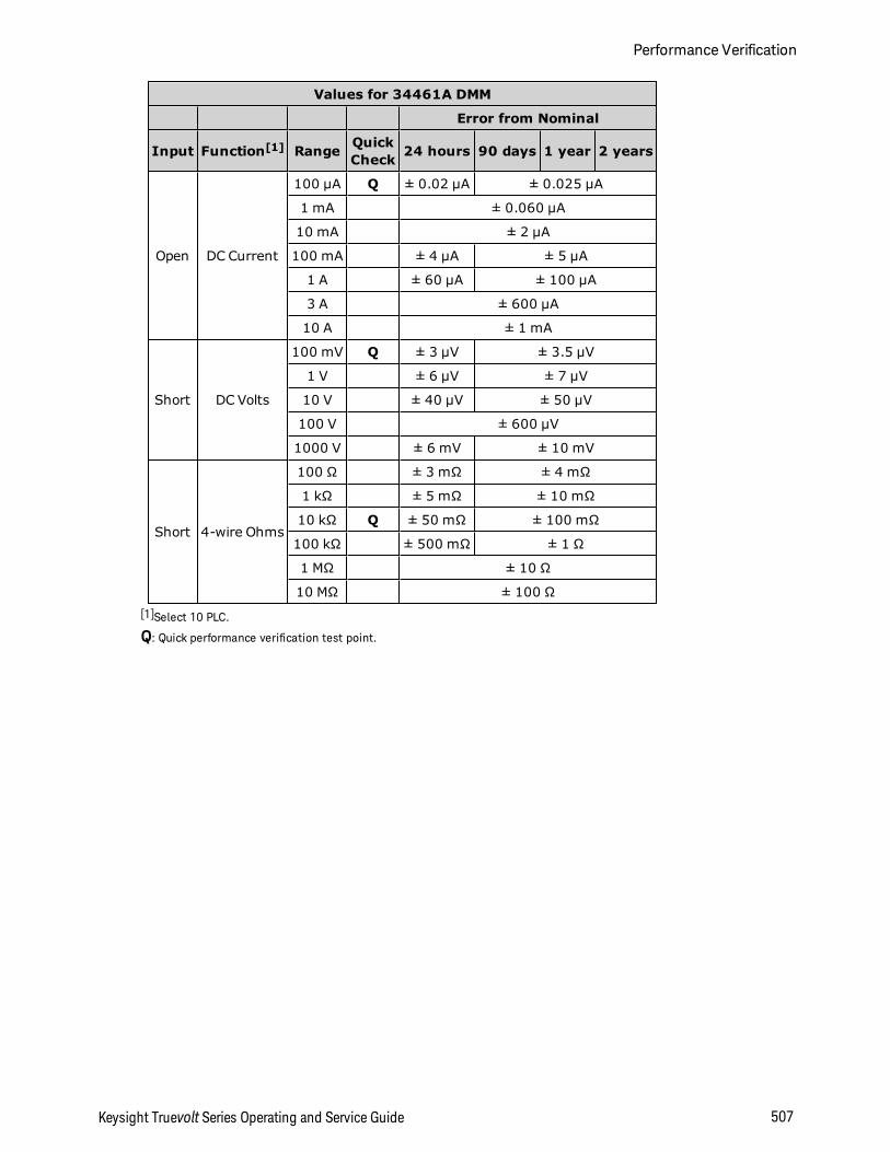
Values for 34461A DMM
Error from Nominal
Input Function[1] Range QuickCheck 24 hours 90 days 1 year 2 years
Open DC Current
100 µA Q ± 0.02 µA ± 0.025 µA
1 mA ± 0.060 µA
10 mA ± 2 µA
100 mA ± 4 µA ± 5 µA
1 A ± 60 µA ± 100 µA
3 A ± 600 µA
10 A ± 1 mA
Short DC Volts
100 mV Q ± 3 µV ± 3.5 µV
1 V ± 6 µV ± 7 µV
10 V ± 40 µV ± 50 µV
100 V ± 600 µV
1000 V ± 6 mV ± 10 mV
Short 4-wire Ohms
100 Ω ± 3 mΩ ± 4 mΩ
1 kΩ ± 5 mΩ ± 10 mΩ
10 kΩ Q ± 50 mΩ ± 100 mΩ
100 kΩ ± 500 mΩ ± 1 Ω
1 MΩ ± 10 Ω
10 MΩ ± 100 Ω[1]Select 10 PLC.
Q: Quick performance verification test point.
Keysight Truevolt Series Operating and Service Guide 507
Performance Verification
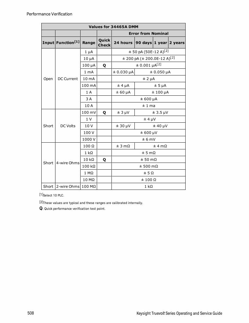
Values for 34465A DMM
Error from Nominal
Input Function[1] Range QuickCheck 24 hours 90 days 1 year 2 years
Open DC Current
1 µA ± 50 pA (50E-12 A)[2]
10 µA ± 200 pA (± 200.0E-12 A)[2]
100 µA Q ± 0.001 µA[2]
1 mA ± 0.030 µA ± 0.050 µA
10 mA ± 2 µA
100 mA ± 4 µA ± 5 µA
1 A ± 60 µA ± 100 µA
3 A ± 600 µA
10 A ± 1 ma
Short DC Volts
100 mV Q ± 3 µV ± 3.5 µV
1 V ± 4 µV
10 V ± 30 µV ± 40 µV
100 V ± 600 µV
1000 V ± 6 mV
Short 4-wire Ohms
100 Ω ± 3 mΩ ± 4 mΩ
1 kΩ ± 5 mΩ
10 kΩ Q ± 50 mΩ
100 kΩ ± 500 mΩ
1 MΩ ± 5 Ω
10 MΩ ± 100 Ω
Short 2-wire Ohms 100 MΩ 1 kΩ
[1]Select 10 PLC.
[2]These values are typical and these ranges are calibrated internally.
Q: Quick performance verification test point.
Performance Verification
508 Keysight Truevolt Series Operating and Service Guide
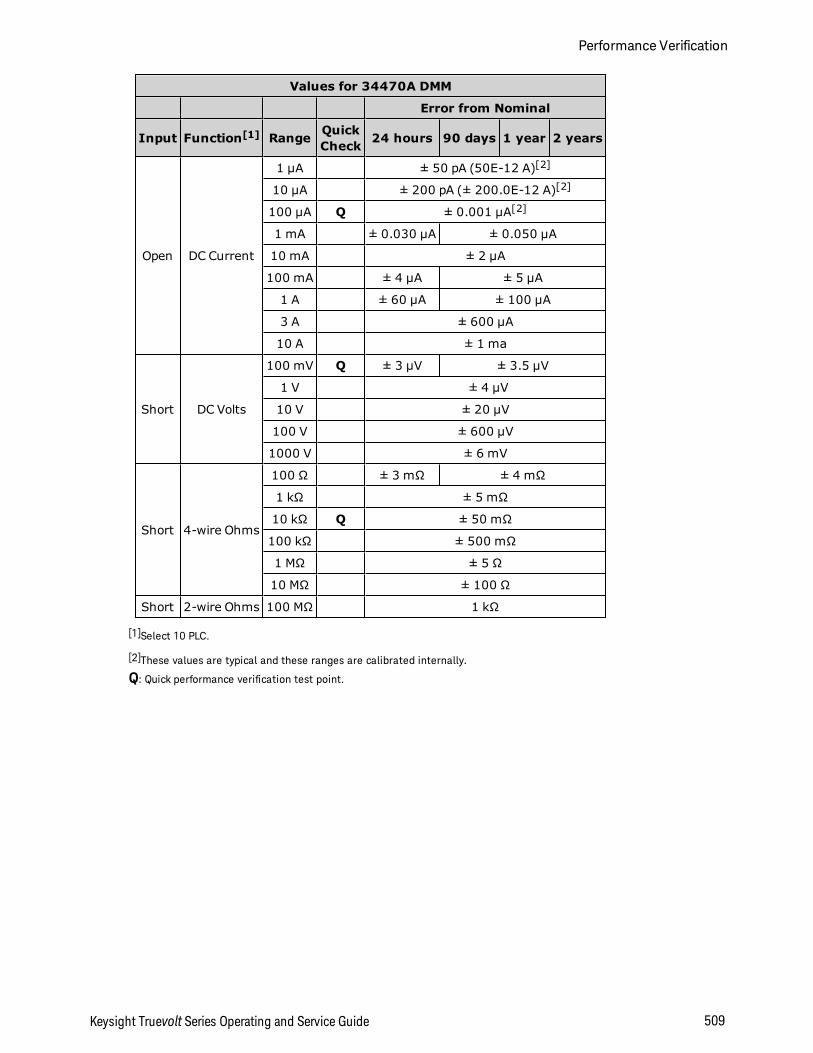
Values for 34470A DMM
Error from Nominal
Input Function[1] Range QuickCheck 24 hours 90 days 1 year 2 years
Open DC Current
1 µA ± 50 pA (50E-12 A)[2]
10 µA ± 200 pA (± 200.0E-12 A)[2]
100 µA Q ± 0.001 µA[2]
1 mA ± 0.030 µA ± 0.050 µA
10 mA ± 2 µA
100 mA ± 4 µA ± 5 µA
1 A ± 60 µA ± 100 µA
3 A ± 600 µA
10 A ± 1 ma
Short DC Volts
100 mV Q ± 3 µV ± 3.5 µV
1 V ± 4 µV
10 V ± 20 µV
100 V ± 600 µV
1000 V ± 6 mV
Short 4-wire Ohms
100 Ω ± 3 mΩ ± 4 mΩ
1 kΩ ± 5 mΩ
10 kΩ Q ± 50 mΩ
100 kΩ ± 500 mΩ
1 MΩ ± 5 Ω
10 MΩ ± 100 Ω
Short 2-wire Ohms 100 MΩ 1 kΩ
[1]Select 10 PLC.
[2]These values are typical and these ranges are calibrated internally.
Q: Quick performance verification test point.
Keysight Truevolt Series Operating and Service Guide 509
Performance Verification
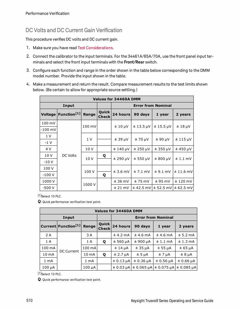
DC Volts and DC Current Gain Verification
This procedure verifies DC volts and DC current gain.
1. Make sure you have read Test Considerations.
2. Connect the calibrator to the input terminals. For the 34461A/65A/70A, use the front panel input ter-minals and select the front input terminals with the Front/Rear switch.
3. Configure each function and range in the order shown in the table below corresponding to the DMMmodel number. Provide the input shown in the table.
4. Make a measurement and return the result. Compare measurement results to the test limits shownbelow. (Be certain to allow for appropriate source settling.)
Values for 34460A DMM
Input Error from Nominal
Voltage Function[1] Range QuickCheck 24 hours 90 days 1 year 2 years
100 mV
DC Volts
100 mV ± 10 µV ± 13.5 µV ± 15.5 µV ± 18 µV-100 mV
1 V1 V ± 39 µV ± 70 µV ± 90 µV ± 115 µV
-1 V
4 V 10 V ± 140 µV ± 250 µV ± 350 µV ± 450 µV
10 V10 V
Q± 290 µV ± 550 µV ± 800 µV ± 1.1 mV
-10 V
100 V100 V ± 3.6 mV ± 7.1 mV ± 9.1 mV ± 11.6 mV
-100 V Q
1000 V1000 V
± 36 mV ± 75 mV ± 95 mV ± 120 mV
-500 V ± 21 mV ± 42.5 mV ± 52.5 mV ± 62.5 mV
[1]Select 10 PLC.
Q: Quick performance verification test point.
Values for 34460A DMM
Input Error from Nominal
Current Function[1] Range QuickCheck 24 hours 90 days 1 year 2 years
2 A
DC Current
3 A ± 4.2 mA ± 4.6 mA ± 4.6 mA ± 5.2 mA
1 A 1 A Q ± 560 µA ± 900 µA ± 1.1 mA ± 1.3 mA
100 mA 100 mA ± 14 µA ± 35 µA ± 55 µA ± 65 µA
10 mA 10 mA Q ± 2.7 µA ± 5 µA ± 7 µA ± 8 µA
1 mA 1 mA ± 0.13 µA ± 0.36 µA ± 0.56 µA ± 0.66 µA
100 µA 100 µA ± 0.03 µA ± 0.065 µA ± 0.075 µA ± 0.085 µA[1]Select 10 PLC.
Q: Quick performance verification test point.
Performance Verification
510 Keysight Truevolt Series Operating and Service Guide

Values for 34460A DMM
Input Error from Nominal
Resistance Function[1] Range QuickCheck 24 hours 90 days 1 year 2 years
100 Ω
4-wire Ohms
100 Ω ± 10 mΩ ± 18 mΩ ± 21 mΩ ± 24 mΩ
1 kΩ 1 kΩ Q ± 38 mΩ ± 120 mΩ ± 150 mΩ ± 180 mΩ
10 kΩ 10 kΩ ± 350 mΩ ± 1.2 Ω ± 1.5 Ω ± 1.8 Ω
100 kΩ 100 kΩ ± 3.5 Ω ± 12 Ω ± 15 Ω ± 18 Ω
1 MΩ 1 MΩ ± 40 Ω ± 120 Ω ± 150 Ω ± 180 Ω
10 MΩ 10 MΩ Q ± 1.6 kΩ ± 2.1 kΩ ± 4.1 kΩ ± 6.1 kΩ
100 MΩ 2-wire Ohms 100 MΩ ± 310 kΩ ± 810 kΩ
[1]Select 10 PLC.
Q: Quick performance verification test point.
Values for 34461A DMM
Input Error from Nominal
Voltage Function[1] Range QuickCheck 24 hours 90 days 1 year 2 years
100 mV
DC Volts
100 mV ± 6 µV ± 7.5 µV ± 8.5 µV ± 10 µV-100 mV
1 V1 V ± 26 µV ± 37 µV ± 47 µV ± 62 µV
-1 V
4 V
10 V
± 100 µV ± 130 µV ± 190 µV ± 230 µV
10 V Q± 190 µV ± 250 µV ± 400 µV ± 500 µV
-10 V
100 V100 V ± 2.6 mV ± 4.1 mV ± 5.1 mV ± 6.6 mV
-100 V Q
1000 V1000 V
± 26 mV ± 45 mV ± 55 mV ± 70 mV
-500 V ± 16 mV ± 27.5 mV ± 32.5 mV ± 40 mV[1]Select 10 PLC.
Q: Quick performance verification test point.
Keysight Truevolt Series Operating and Service Guide 511
Performance Verification
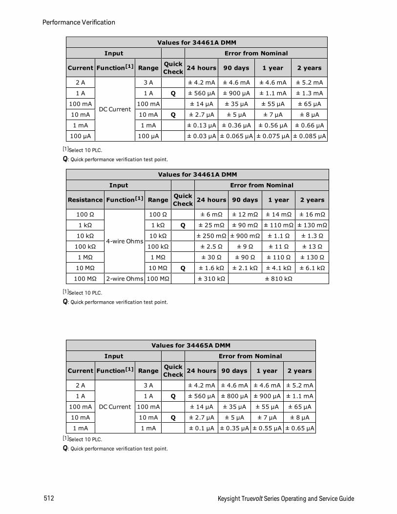
Values for 34461A DMM
Input Error from Nominal
Current Function[1] Range QuickCheck 24 hours 90 days 1 year 2 years
2 A
DC Current
3 A ± 4.2 mA ± 4.6 mA ± 4.6 mA ± 5.2 mA
1 A 1 A Q ± 560 µA ± 900 µA ± 1.1 mA ± 1.3 mA
100 mA 100 mA ± 14 µA ± 35 µA ± 55 µA ± 65 µA
10 mA 10 mA Q ± 2.7 µA ± 5 µA ± 7 µA ± 8 µA
1 mA 1 mA ± 0.13 µA ± 0.36 µA ± 0.56 µA ± 0.66 µA
100 µA 100 µA ± 0.03 µA ± 0.065 µA ± 0.075 µA ± 0.085 µA
[1]Select 10 PLC.
Q: Quick performance verification test point.
Values for 34461A DMM
Input Error from Nominal
Resistance Function[1] Range QuickCheck 24 hours 90 days 1 year 2 years
100 Ω
4-wire Ohms
100 Ω ± 6 mΩ ± 12 mΩ ± 14 mΩ ± 16 mΩ
1 kΩ 1 kΩ Q ± 25 mΩ ± 90 mΩ ± 110 mΩ ± 130 mΩ
10 kΩ 10 kΩ ± 250 mΩ ± 900 mΩ ± 1.1 Ω ± 1.3 Ω
100 kΩ 100 kΩ ± 2.5 Ω ± 9 Ω ± 11 Ω ± 13 Ω
1 MΩ 1 MΩ ± 30 Ω ± 90 Ω ± 110 Ω ± 130 Ω
10 MΩ 10 MΩ Q ± 1.6 kΩ ± 2.1 kΩ ± 4.1 kΩ ± 6.1 kΩ
100 MΩ 2-wire Ohms 100 MΩ ± 310 kΩ ± 810 kΩ
[1]Select 10 PLC.
Q: Quick performance verification test point.
Values for 34465A DMM
Input Error from Nominal
Current Function[1] Range QuickCheck 24 hours 90 days 1 year 2 years
2 A
DC Current
3 A ± 4.2 mA ± 4.6 mA ± 4.6 mA ± 5.2 mA
1 A 1 A Q ± 560 µA ± 800 µA ± 900 µA ± 1.1 mA
100 mA 100 mA ± 14 µA ± 35 µA ± 55 µA ± 65 µA
10 mA 10 mA Q ± 2.7 µA ± 5 µA ± 7 µA ± 8 µA
1 mA 1 mA ± 0.1 µA ± 0.35 µA ± 0.55 µA ± 0.65 µA[1]Select 10 PLC.
Q: Quick performance verification test point.
Performance Verification
512 Keysight Truevolt Series Operating and Service Guide
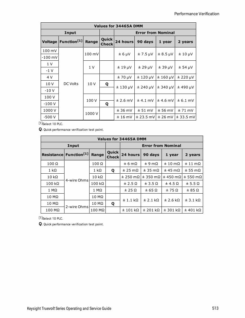
Values for 34465A DMM
Input Error from Nominal
Voltage Function[1] Range QuickCheck 24 hours 90 days 1 year 2 years
100 mV
DC Volts
100 mV ± 6 µV ± 7.5 µV ± 8.5 µV ± 10 µV-100 mV
1 V1 V ± 19 µV ± 29 µV ± 39 µV ± 54 µV
-1 V
4 V
10 V
± 70 µV ± 120 µV ± 160 µV ± 220 µV
10 V Q± 130 µV ± 240 µV ± 340 µV ± 490 µV
-10 V
100 V100 V ± 2.6 mV ± 4.1 mV ± 4.6 mV ± 6.1 mV
-100 V Q
1000 V1000 V
± 36 mV ± 51 mV ± 56 mV ± 71 mV
-500 V ± 16 mV ± 23.5 mV ± 26 mV ± 33.5 mV[1]Select 10 PLC.
Q: Quick performance verification test point.
Values for 34465A DMM
Input Error from Nominal
Resistance Function[1] Range QuickCheck 24 hours 90 days 1 year 2 years
100 Ω
4-wire Ohms
100 Ω ± 6 mΩ ± 9 mΩ ± 10 mΩ ± 11 mΩ
1 kΩ 1 kΩ Q ± 25 mΩ ± 35 mΩ ± 45 mΩ ± 55 mΩ
10 kΩ 10 kΩ ± 250 mΩ ± 350 mΩ ± 450 mΩ ± 550 mΩ
100 kΩ 100 kΩ ± 2.5 Ω ± 3.5 Ω ± 4.5 Ω ± 5.5 Ω
1 MΩ 1 MΩ ± 25 Ω ± 65 Ω ± 75 Ω ± 85 Ω
10 MΩ 10 MΩ± 1.1 kΩ ± 2.1 kΩ ± 2.6 kΩ ± 3.1 kΩ
10 MΩ2-wire Ohms
10 MΩ Q
100 MΩ 100 MΩ ± 101 kΩ ± 201 kΩ ± 301 kΩ ± 401 kΩ
[1]Select 10 PLC.
Q: Quick performance verification test point.
Keysight Truevolt Series Operating and Service Guide 513
Performance Verification
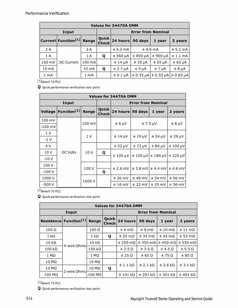
Values for 34470A DMM
Input Error from Nominal
Current Function[1] Range QuickCheck 24 hours 90 days 1 year 2 years
2 A
DC Current
3 A ± 4.2 mA ± 4.6 mA ± 5.2 mA
1 A 1 A Q ± 560 µA ± 800 µA ± 900 µA ± 1.1 mA
100 mA 100 mA ± 14 µA ± 35 µA ± 55 µA ± 65 µA
10 mA 10 mA Q ± 2.7 µA ± 5 µA ± 7 µA ± 8 µA
1 mA 1 mA ± 0.1 µA ± 0.35 µA ± 0.55 µA ± 0.65 µA[1]Select 10 PLC.
Q: Quick performance verification test point.
Values for 34470A DMM
Input Error from Nominal
Voltage Function[1] Range QuickCheck 24 hours 90 days 1 year 2 years
100 mV
DC Volts
100 mV ± 6 µV ± 7.5 µV ± 8 µV-100 mV
1 V1 V ± 14 µV ± 19 µV ± 24 µV ± 29 µV
-1 V
4 V
10 V
± 52 µV ± 72 µV ± 84 µV ± 100 µV
10 V Q± 100 µV ± 150 µV ± 180 µV ± 220 µV
-10 V
100 V100 V ± 2.6 mV ± 3.8 mV ± 4.4 mV ± 4.6 mV
-100 V Q
1000 V1000 V
± 36 mV ± 48 mV ± 54 mV ± 56 mV
-500 V ± 16 mV ± 22 mV ± 25 mV ± 36 mV[1]Select 10 PLC.
Q: Quick performance verification test point.
Values for 34470A DMM
Input Error from Nominal
Resistance Function[1] Range QuickCheck 24 hours 90 days 1 year 2 years
100 Ω
4-wire Ohms
100 Ω ± 6 mΩ ± 9 mΩ ± 10 mΩ ± 11 mΩ
1 kΩ 1 kΩ Q ± 25 mΩ ± 35 mΩ ± 45 mΩ ± 55 mΩ
10 kΩ 10 kΩ ± 250 mΩ ± 350 mΩ ± 450 mΩ ± 550 mΩ
100 kΩ 100 kΩ ± 2.5 Ω ± 3.5 Ω ± 4.5 Ω ± 5.5 Ω
1 MΩ 1 MΩ ± 25 Ω ± 65 Ω ± 75 Ω ± 85 Ω
10 MΩ 10 MΩ± 1.1 kΩ ± 2.1 kΩ ± 2.6 kΩ ± 3.1 kΩ
10 MΩ2-wire Ohms
10 MΩ Q
100 MΩ 100 MΩ ± 101 kΩ ± 201 kΩ ± 301 kΩ ± 401 kΩ
[1]Select 10 PLC.
Q: Quick performance verification test point.
Performance Verification
514 Keysight Truevolt Series Operating and Service Guide
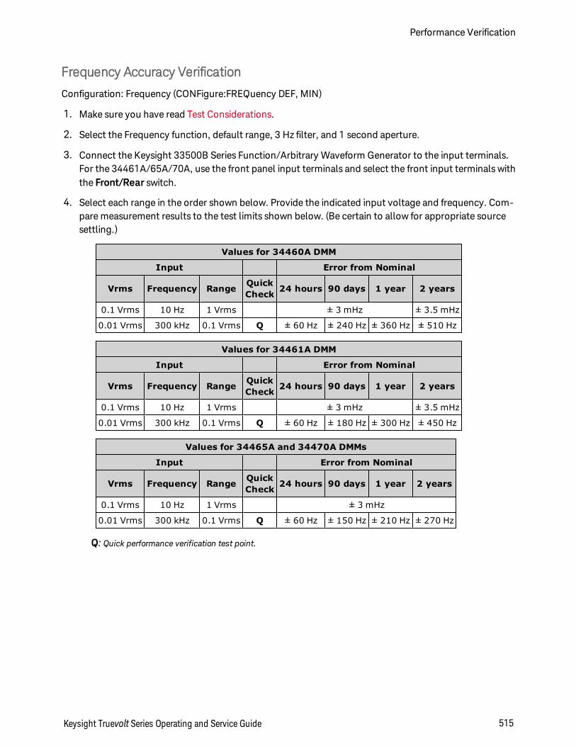
Frequency Accuracy Verification
Configuration: Frequency (CONFigure:FREQuency DEF, MIN)
1. Make sure you have read Test Considerations.
2. Select the Frequency function, default range, 3 Hz filter, and 1 second aperture.
3. Connect the Keysight 33500B Series Function/Arbitrary Waveform Generator to the input terminals.For the 34461A/65A/70A, use the front panel input terminals and select the front input terminals withthe Front/Rear switch.
4. Select each range in the order shown below. Provide the indicated input voltage and frequency. Com-pare measurement results to the test limits shown below. (Be certain to allow for appropriate sourcesettling.)
Values for 34460A DMM
Input Error from Nominal
Vrms Frequency Range QuickCheck 24 hours 90 days 1 year 2 years
0.1 Vrms 10 Hz 1 Vrms ± 3 mHz ± 3.5 mHz
0.01 Vrms 300 kHz 0.1 Vrms Q ± 60 Hz ± 240 Hz ± 360 Hz ± 510 Hz
Values for 34461A DMM
Input Error from Nominal
Vrms Frequency Range QuickCheck 24 hours 90 days 1 year 2 years
0.1 Vrms 10 Hz 1 Vrms ± 3 mHz ± 3.5 mHz
0.01 Vrms 300 kHz 0.1 Vrms Q ± 60 Hz ± 180 Hz ± 300 Hz ± 450 Hz
Values for 34465A and 34470A DMMs
Input Error from Nominal
Vrms Frequency Range QuickCheck 24 hours 90 days 1 year 2 years
0.1 Vrms 10 Hz 1 Vrms ± 3 mHz
0.01 Vrms 300 kHz 0.1 Vrms Q ± 60 Hz ± 150 Hz ± 210 Hz ± 270 Hz
Q: Quick performance verification test point.
Keysight Truevolt Series Operating and Service Guide 515
Performance Verification
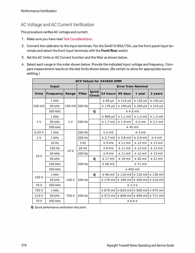
AC Voltage and AC Current Verification
This procedure verifies AC voltage and current.
1. Make sure you have read Test Considerations.
2. Connect the calibrator to the input terminals. For the 34461A/65A/70A, use the front panel input ter-minals and select the front input terminals with the Front/Rear switch.
3. Set the AC Volts or AC Current function and the filter as shown below.
4. Select each range in the order shown below. Provide the indicated input voltage and frequency. Com-pare measurement results to the test limits shown below. (Be certain to allow for appropriate sourcesettling.)
ACV Values for 34460A DMM
Input Error from Nominal
Vrms Frequency Range Filter QuickCheck 24 hours 90 days 1 year 2 years
100 mV
1 kHz
100 mV 200 Hz
± 90 µV ± 110 µV ± 120 µV ± 130 µV
50 kHz ± 170 µV ± 190 µV ± 200 µV ± 210 µV
300 kHz Q ± 4.5 mV
1 V
1 kHz
1 V 200 Hz
± 900 µV ± 1.1 mV ± 1.2 mV ± 1.3 mV
50 kHz ± 1.7 mV ± 1.9 mV ± 2 mV ± 2.1 mV
300 kHz ± 45 mV
0.03 V 1 kHz
10 V
200 Hz ± 2 mV ± 3 mV
1 V 1 kHz 200 Hz ± 2.7 mV ± 3.8 mV ± 3.9 mV ± 4 mV
10 V
10 Hz 3 Hz ± 9 mV ± 11 mV ± 12 mV ± 13 mV
100 Hz 20 Hz ± 9 mV ± 11 mV ± 12 mV ± 13 mV
20 kHz 200 Hz ± 9 mV ± 11 mV ± 12 mV ± 13 mV
50 kHz
200 Hz
Q ± 17 mV ± 19 mV ± 20 mV ± 21 mV
100 kHz ± 66 mV ± 71 mV
300 kHz ± 450 mV
100 V1 kHz
100 V 200 Hz
Q ± 90 mV ± 110 mV ± 120 mV ± 130 mV
50 kHz ± 170 mV ± 190 mV ± 200 mV ± 210 mV
70 V 300 kHz ± 3.3 V
750 V 1 kHz
750 V 200 Hz
± 675 mV ± 825 mV ± 900 mV ± 975 mV
210 V 50 kHz ± 573 mV ± 669 mV ± 690 mV ± 711 mV
70 V 300 kHz ± 6.6 V
Q: Quick performance verification test point.
Performance Verification
516 Keysight Truevolt Series Operating and Service Guide
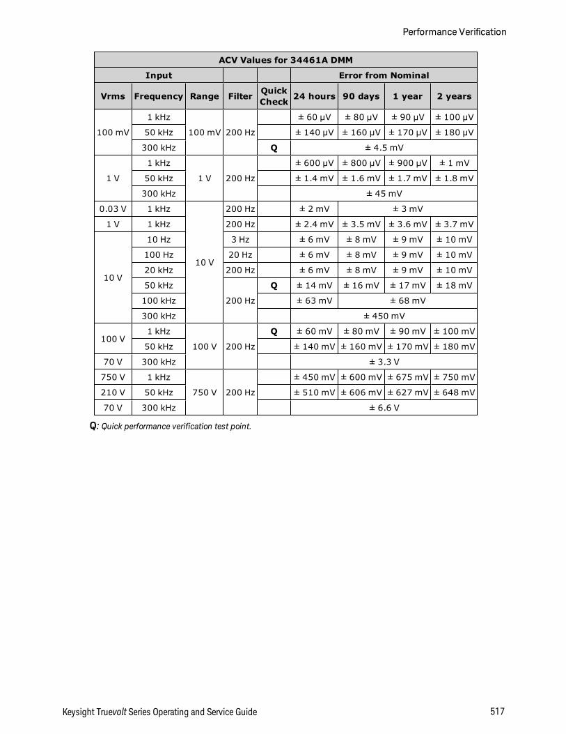
ACV Values for 34461A DMM
Input Error from Nominal
Vrms Frequency Range Filter QuickCheck 24 hours 90 days 1 year 2 years
100 mV
1 kHz
100 mV 200 Hz
± 60 µV ± 80 µV ± 90 µV ± 100 µV
50 kHz ± 140 µV ± 160 µV ± 170 µV ± 180 µV
300 kHz Q ± 4.5 mV
1 V
1 kHz
1 V 200 Hz
± 600 µV ± 800 µV ± 900 µV ± 1 mV
50 kHz ± 1.4 mV ± 1.6 mV ± 1.7 mV ± 1.8 mV
300 kHz ± 45 mV
0.03 V 1 kHz
10 V
200 Hz ± 2 mV ± 3 mV
1 V 1 kHz 200 Hz ± 2.4 mV ± 3.5 mV ± 3.6 mV ± 3.7 mV
10 V
10 Hz 3 Hz ± 6 mV ± 8 mV ± 9 mV ± 10 mV
100 Hz 20 Hz ± 6 mV ± 8 mV ± 9 mV ± 10 mV
20 kHz 200 Hz ± 6 mV ± 8 mV ± 9 mV ± 10 mV
50 kHz
200 Hz
Q ± 14 mV ± 16 mV ± 17 mV ± 18 mV
100 kHz ± 63 mV ± 68 mV
300 kHz ± 450 mV
100 V1 kHz
100 V 200 Hz
Q ± 60 mV ± 80 mV ± 90 mV ± 100 mV
50 kHz ± 140 mV ± 160 mV ± 170 mV ± 180 mV
70 V 300 kHz ± 3.3 V
750 V 1 kHz
750 V 200 Hz
± 450 mV ± 600 mV ± 675 mV ± 750 mV
210 V 50 kHz ± 510 mV ± 606 mV ± 627 mV ± 648 mV
70 V 300 kHz ± 6.6 V
Q: Quick performance verification test point.
Keysight Truevolt Series Operating and Service Guide 517
Performance Verification
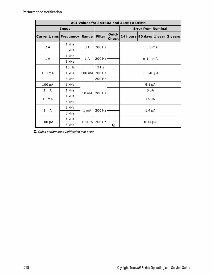
ACI Values for 34460A and 34461A DMMs
Input Error from Nominal
Current, rms Frequency Range Filter QuickCheck 24 hours 90 days 1 year 2 years
2 A1 kHz
3 A 200 Hz ± 5.8 mA5 kHz
1 A1 kHz
1 A 200 Hz ± 1.4 mA5 kHz
100 mA
10 Hz
100 mA
3 Hz
± 140 µA1 kHz 200 Hz
5 kHz 200 Hz
100 µA 1 kHz
10 mA 200 Hz
4.1 µA
1 mA 1 kHz 5 µA
10 mA1 kHz
14 µA5 kHz
1 mA1 kHz
1 mA 200 Hz 1.4 µA5 kHz
100 µA1 kHz
100 µA 200 Hz 0.14 µA5 kHz Q
Q: Quick performance verification test point.
Performance Verification
518 Keysight Truevolt Series Operating and Service Guide
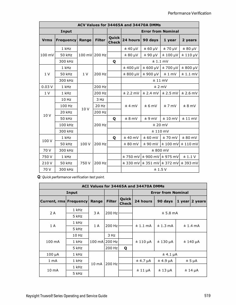
ACV Values for 34465A and 34470A DMMs
Input Error from Nominal
Vrms Frequency Range Filter QuickCheck 24 hours 90 days 1 year 2 years
100 mV
1 kHz
100 mV 200 Hz
± 40 µV ± 60 µV ± 70 µV ± 80 µV
50 kHz ± 80 µV ± 90 µV ± 100 µV ± 110 µV
300 kHz Q ± 1.1 mV
1 V
1 kHz
1 V 200 Hz
± 400 µV ± 600 µV ± 700 µV ± 800 µV
50 kHz ± 800 µV ± 900 µV ± 1 mV ± 1.1 mV
300 kHz ± 11 mV
0.03 V 1 kHz
10 V
200 Hz ± 2 mV
1 V 1 kHz 200 Hz ± 2.2 mV ± 2.4 mV ± 2.5 mV ± 2.6 mV
10 V
10 Hz 3 Hz
± 4 mV ± 6 mV ± 7 mV ± 8 mV100 Hz 20 Hz
20 kHz 200 Hz
50 kHz
200 Hz
Q ± 8 mV ± 9 mV ± 10 mV ± 11 mV
100 kHz ± 20 mV
300 kHz ± 110 mV
100 V1 kHz
100 V 200 Hz
Q ± 40 mV ± 60 mV ± 70 mV ± 80 mV
50 kHz ± 80 mV ± 90 mV ± 100 mV ± 110 mV
70 V 300 kHz ± 800 mV
750 V 1 kHz
750 V 200 Hz
± 750 mV ± 900 mV ± 975 mV ± 1.1 V
210 V 50 kHz ± 330 mV ± 351 mV ± 372 mV ± 393 mV
70 V 300 kHz ± 1.5 V
Q: Quick performance verification test point.
ACI Values for 34465A and 34470A DMMs
Input Error from Nominal
Current, rms Frequency Range Filter QuickCheck 24 hours 90 days 1 year 2 years
2 A1 kHz
3 A 200 Hz ± 5.8 mA5 kHz
1 A1 kHz
1 A 200 Hz ± 1.1 mA ± 1.3 mA ± 1.4 mA5 kHz
100 mA
10 Hz
100 mA
3 Hz
± 110 µA ± 130 µA ± 140 µA1 kHz 200 Hz
5 kHz 200 Hz Q
100 µA 1 kHz
10 mA 200 Hz
± 4.1 µA
1 mA 1 kHz ± 4.7 µA ± 4.9 µA ± 5 µA
10 mA1 kHz
± 11 µA ± 13 µA ± 14 µA5 kHz
Keysight Truevolt Series Operating and Service Guide 519
Performance Verification
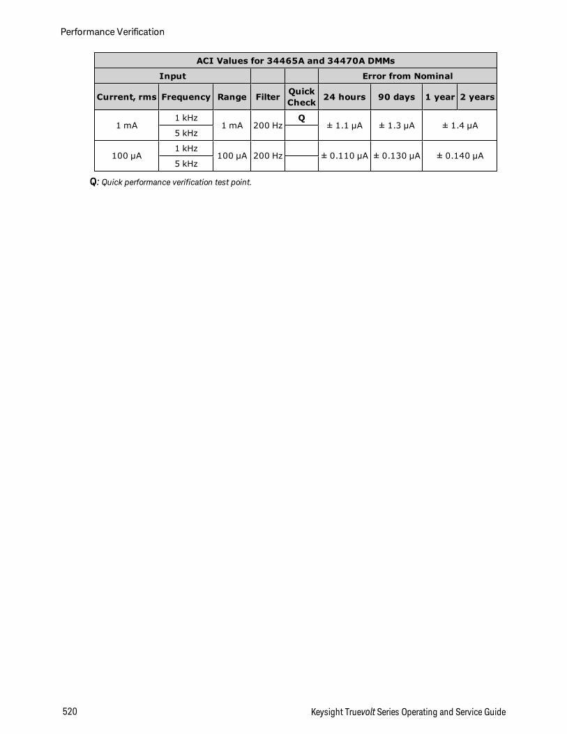
ACI Values for 34465A and 34470A DMMs
Input Error from Nominal
Current, rms Frequency Range Filter QuickCheck 24 hours 90 days 1 year 2 years
1 mA1 kHz
1 mA 200 HzQ
± 1.1 µA ± 1.3 µA ± 1.4 µA5 kHz
100 µA1 kHz
100 µA 200 Hz ± 0.110 µA ± 0.130 µA ± 0.140 µA5 kHz
Q: Quick performance verification test point.
Performance Verification
520 Keysight Truevolt Series Operating and Service Guide
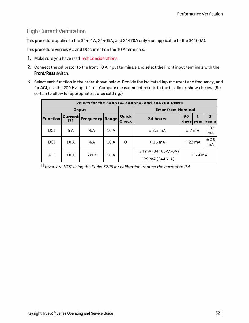
High Current Verification
This procedure applies to the 34461A, 34465A, and 34470A only (not applicable to the 34460A).
This procedure verifies AC and DC current on the 10 A terminals.
1. Make sure you have read Test Considerations.
2. Connect the calibrator to the front 10 A input terminals and select the Front input terminals with theFront/Rear switch.
3. Select each function in the order shown below. Provide the indicated input current and frequency, andfor ACI, use the 200 Hz input filter. Compare measurement results to the test limits shown below. (Becertain to allow for appropriate source settling.)
Values for the 34461A, 34465A, and 34470A DMMs
Input Error from Nominal
Function Current[1] Frequency Range Quick
Check 24 hours 90days
1year
2years
DCI 5 A N/A 10 A ± 3.5 mA ± 7 mA ± 8.5mA
DCI 10 A N/A 10 A Q ± 16 mA ± 23 mA ± 26mA
ACI 10 A 5 kHz 10 A± 24 mA (34465A/70A)
± 29 mA (34461A)± 29 mA
[1] If you are NOT using the Fluke 5725 for calibration, reduce the current to 2 A.
Keysight Truevolt Series Operating and Service Guide 521
Performance Verification
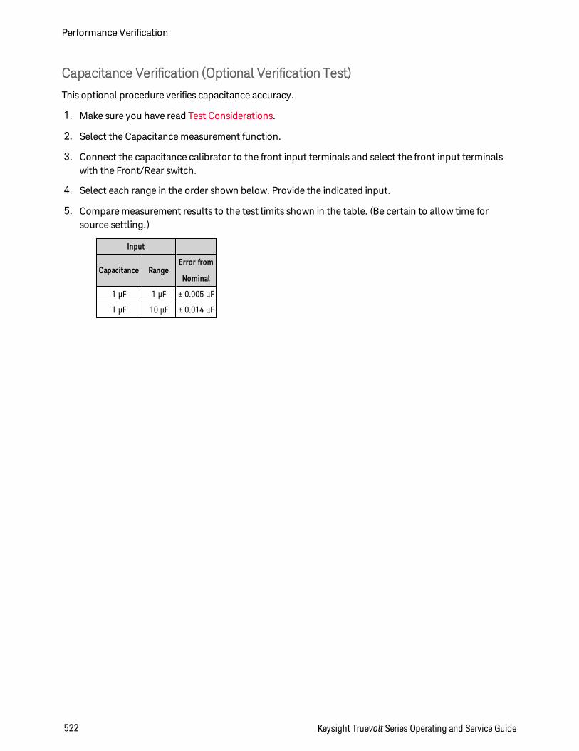
Capacitance Verification (Optional Verification Test)
This optional procedure verifies capacitance accuracy.
1. Make sure you have read Test Considerations.
2. Select the Capacitance measurement function.
3. Connect the capacitance calibrator to the front input terminals and select the front input terminalswith the Front/Rear switch.
4. Select each range in the order shown below. Provide the indicated input.
5. Compare measurement results to the test limits shown in the table. (Be certain to allow time forsource settling.)
Input
Capacitance RangeError from
Nominal
1 μF 1 μF ± 0.005 μF
1 μF 10 μF ± 0.014 μF
Performance Verification
522 Keysight Truevolt Series Operating and Service Guide
Calibration Adjustment ProceduresYou will need a test input cable and connectors set and a low thermal input short, Keysight 34172B, to cal-ibrate the instrument (see Input Connections). Two input shorts are recommended for the34461A/65A/70A.
l Calibration Process Overview
l 34460A and 34461A Calibration Procedures
l 34465A and 34470A Calibration Procedures
Keysight Truevolt Series Operating and Service Guide 523
Calibration Adjustment Procedures
Calibration Procedures
This section contains procedures for adjusting the instrument’s performance (calibration).
There is no separate calibration for Diode or Continuity, because these functions arebased on the resistance measurement, which is calibrated. Also, there is no calibrationfor gate time because this functionality is controlled by digital logic. There is no cal-ibration for capacitance gain and, for the 34465A and 34470A, no calibration on the 1,10, and 100 µA DCI ranges
Use one of the following sets of procedures based on the DMM model number:
l 34460A and 34461A Calibration Proceduresl 34465A and 34470A Calibration Procedures
Closed–Case Electronic Calibration
The instrument uses closed-case electronic calibration; no internal mechanical adjustments are required.The instrument calculates correction factors based on reference signals that you apply and stores the cor-rection factors in non-volatile memory. This data is not changed by cycling power, *RST, orSYSTem:PRESet.
Keysight Technologies Calibration Services
Keysight Technologies offers calibration services using automated calibration systems that enable Key-sight to provide calibration at competitive prices. See Types of Service Available for information on con-tacting Keysight.
Calibration Adjustment Interval
The instrument should be calibrated on a regular interval determined by the accuracy requirements ofyour application. A 1-year interval is adequate for most applications. Accuracy specifications are war-ranted only if calibration is made at regular calibration intervals. Keysight Technologies never recom-mends calibration adjustment intervals beyond two years.
Calibration is Recommended
Whatever calibration interval you select, Keysight Technologies recommends that complete re-calibrationshould always be performed at the calibration interval. This ensures that the instrument will remain withinspecifications for the next calibration interval and provides the best long-term stability. Performance datameasured during performance verification tests does not mean that the instrument will remain withinthese limits unless the calibration adjustments are performed. Use the calibration count to verify that allcalibration adjustments have been performed.
Time Required for Calibration Adjustment
The instrument can be automatically calibrated under computer control, including complete calibrationadjustment procedure and performance verification tests, in less than 30 minutes once the instrument iswarmed–up (see Test Considerations).
Calibration Adjustment Procedures
524 Keysight Truevolt Series Operating and Service Guide
Automating Calibration Adjustment Procedures
The calibration procedures demonstrate front panel calibration. You can automate the complete veri-fication and calibration procedures outlined in this manual. You can program the instrument con-figurations specified for each test over the remote interface. You can then enter read back verification datainto a test program and compare the results to the appropriate test limit values.
The instrument must be unsecured to calibrate. See Calibration Security for details.
Refer to the CALibration Subsystem for information on SCPI programming.
Input Connections
Test connections to the instrument are best accomplished using a Keysight Technologies 34172B cal-ibration short for low–thermal offset measurements and a 34171B DMM connector configured to inter-face to the calibrator output. Shielded, twisted–pair, PTFE interconnect cables of minimum length arerecommended between the calibrator and the multimeter to reduce settling and noise errors. HI and HISense should be a twisted pair. LO and LO Sense should be a twisted pair. Cable shields should be earthground referenced. This configuration is recommended for noise reduction and settling time performanceduring calibration.
Test Considerations
Errors may be induced by AC signals present on the input leads during a self–test. Long test leads can alsoact as an antenna causing pick–up of AC signals.
For optimum performance:
l Ensure that the calibration ambient temperature (Tcal) is stable and between 18 °C and 28 °C. Ideallythe calibration should be performed at 23 °C ±2 °C.
l Ensure ambient relative humidity is less than 80%.
l Allow a 90 minute warm–up period with a copper short connected.
l Connect the input cable shields to earth ground. Except where noted in the procedures, connect thecalibrator LO source to earth ground at the calibrator. It is important that the LO to earth ground con-nection be made at only one place in the circuit to avoid ground loops.
Because the instrument is capable of making highly accurate measurements, you must take care to ensurethat the calibration standards and test procedures do not introduce additional errors. Ideally, the stand-ards used to verify and adjust the instrument should be an order of magnitude more accurate than eachinstrument range full scale error specification.
For 2-wire ohms measurements, remove lead resistance by doing a null measurement with the leads shor-ted or with a precision 4–terminal low thermal short. For offset calibration a 4–terminal low thermal shortis required.
Keysight Truevolt Series Operating and Service Guide 525
Calibration Adjustment Procedures
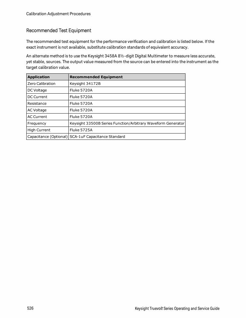
Recommended Test Equipment
The recommended test equipment for the performance verification and calibration is listed below. If theexact instrument is not available, substitute calibration standards of equivalent accuracy.
An alternate method is to use the Keysight 3458A 8½-digit Digital Multimeter to measure less accurate,yet stable, sources. The output value measured from the source can be entered into the instrument as thetarget calibration value.
Application Recommended Equipment
Zero Calibration Keysight 34172B
DC Voltage Fluke 5720A
DC Current Fluke 5720A
Resistance Fluke 5720A
AC Voltage Fluke 5720A
AC Current Fluke 5720A
Frequency Keysight 33500B Series Function/Arbitrary Waveform Generator
High Current Fluke 5725A
Capacitance (Optional) SCA-1uF Capacitance Standard
Calibration Adjustment Procedures
526 Keysight Truevolt Series Operating and Service Guide
Calibration Adjustment Process
The following general procedure is recommended to complete a full calibration adjustment.
1. Read Test Considerations.
2. Perform the performance verification tests to characterize the instrument (incoming data).
3. Unsecure the instrument for calibration (see Calibration Security).
4. Perform the calibration procedures (see Calibration Procedures).
5. Secure the instrument against calibration (see Calibration Security).
6. Note the security code and calibration count in the instrument’s maintenance records.
7. Perform the performance verification tests to verify the calibration.
Keysight Truevolt Series Operating and Service Guide 527
Calibration Adjustment Procedures
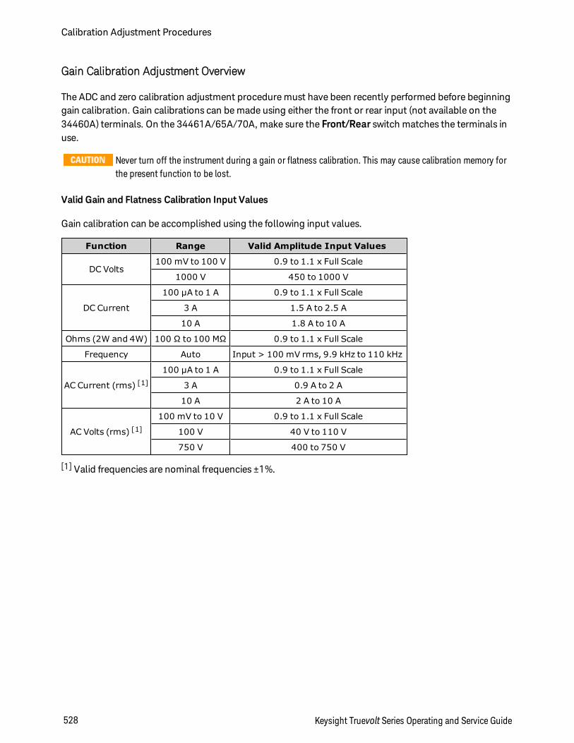
Gain Calibration Adjustment Overview
The ADC and zero calibration adjustment procedure must have been recently performed before beginninggain calibration. Gain calibrations can be made using either the front or rear input (not available on the34460A) terminals. On the 34461A/65A/70A, make sure the Front/Rear switch matches the terminals inuse.
Never turn off the instrument during a gain or flatness calibration. This may cause calibration memory forthe present function to be lost.
Valid Gain and Flatness Calibration Input Values
Gain calibration can be accomplished using the following input values.
Function Range Valid Amplitude Input Values
DC Volts100 mV to 100 V 0.9 to 1.1 x Full Scale
1000 V 450 to 1000 V
DC Current
100 µA to 1 A 0.9 to 1.1 x Full Scale
3 A 1.5 A to 2.5 A
10 A 1.8 A to 10 A
Ohms (2W and 4W) 100 Ω to 100 MΩ 0.9 to 1.1 x Full Scale
Frequency Auto Input > 100 mV rms, 9.9 kHz to 110 kHz
AC Current (rms) [1]
100 µA to 1 A 0.9 to 1.1 x Full Scale
3 A 0.9 A to 2 A
10 A 2 A to 10 A
AC Volts (rms) [1]
100 mV to 10 V 0.9 to 1.1 x Full Scale
100 V 40 V to 110 V
750 V 400 to 750 V
[1] Valid frequencies are nominal frequencies ±1%.
Calibration Adjustment Procedures
528 Keysight Truevolt Series Operating and Service Guide
Gain and Flatness Calibration Adjustment Overview
The instrument stores new flatness correction constants each time this procedure is followed. Flatness con-stants adjust the DMM for AC Volts and AC current measurements across the usable input frequencyband. The flatness constant is computed from the calibration value entered for the calibration commandand from measurements made automatically during the calibration procedure.
Calibrations for each range and frequency should be performed in the order shown.
Flatness Calibration Considerations
The ADC and zero calibration adjustment procedure must have been recently performed before beginninggain calibration. Flatness calibrations can be made using either the front or the rear input terminals. Onthe 34461A/65A/70A, make sure the Front/Rear switch matches the terminals in use.
Never turn off the instrument during a gain or flatness calibration. This may cause calibration memory forthe present function to be lost.
Gain Calibration
The instrument calculates and stores gain corrections for each input value. The gain constant is computedfrom the calibration value entered for the calibration command and from measurements made auto-matically during the calibration procedure.
Most measurement functions and ranges have gain calibration procedures, and calibration for each func-tion should be performed in the order shown.
Keysight Truevolt Series Operating and Service Guide 529
Calibration Adjustment Procedures

Entering Calibration Values and Storing Calibration Constants
Selecting the Calibration Mode
Use the CALibration:ADC? query to begin ADC calibration. The response to this query indicates a suc-cessful calibration (0) or a failure (1). Following the ADC calibration, use the measurement commands toset the DMM measurement parameters and functions for the mode being calibrated.
Front Panel: [Utility] > Test/Admin > Calibrate > Perform Cal > Cal Value > Perform ADC Cal
Entering Calibration Values
To enter a calibration value from the remote interface use CALibration:VALue <value> followed by theCALibration? query. The response to the query indicates whether the calibration is valid.
Front Panel: [Utility] > Test/Admin > Calibrate > Perform Cal > Cal Value > (enter value) > PerformCal Step
Storing the Calibration Constants
To store calibration values in non-volatile memory, use CALibration:STORe.
Front Panel: [Utility] > Test/Admin > Calibrate > Save Cal Values
You must have performed a successful calibration immediately before pressing Save Cal Values.
Calibration Adjustment Procedures
530 Keysight Truevolt Series Operating and Service Guide
Calibration Security
This section describes the instrument's calibration security system. If you forget the security code, you canoverride calibration security.
Security Overview
A security code (calibration password) prevents accidental or unauthorized instrument calibration.
l When shipped from the factory, the instrument is secured, with the security code (calibration pass-word) set to AT3446XA.
l The same security code must be used for front panel and remote operation. If you secure the instru-ment from the front panel, use that same code to unsecure it from the remote interface.
l This setting is non-volatile; it will not be changed by power cycling or *RST or SYSTem:PRESet.
l Security code rules:Unquoted string up to 12 charactersMust start with letter (A-Z)May contain letters, numbers (0-9) and underscores
l Front Panel: [Utility] > Test / Admin > Security
l SCPI: CALibration:SECure:STATe
Keysight Truevolt Series Operating and Service Guide 531
Calibration Adjustment Procedures
Calibration Message
You can store a message of up to 40 characters in calibration memory. For example, you could store thedate of the last calibration, the date the next calibration is due, or the name and phone number of the per-son responsible for calibration.
To read the calibration message, press Utility > Test/Admin > Calibrate or send CALibration:STRing?from the remote interface.
To change the calibration message, unsecure the instrument and press Utility > Test/Admin > Calibrate> Edit Cal String or send CALibration:STRing "<string>" from the remote interface.
Calibration Adjustment Procedures
532 Keysight Truevolt Series Operating and Service Guide
Calibration Count
You can query the instrument to determine how many calibrations have been performed. Because thevalue increments each time you store the calibration constants, a complete calibration adds many counts.The calibration count also increments whenever you save a calibration string, change the calibration pass-word, or override the calibration security.
Your instrument was calibrated at the factory. When you receive your instrument, be sure to read thecount to determine its initial value.
To read the calibration count, press [Utility] > Test/Admin > Calibrate on the front panel or sendCALibration:COUNt? from the remote interface. You can read the calibration count regardless of whetherthe instrument is secured.
Keysight Truevolt Series Operating and Service Guide 533
Calibration Adjustment Procedures

Aborting a Calibration in Progress
Sometimes it may be necessary to abort a calibration. You can abort a calibration at any time on any mod-ule by turning off the power or issuing a remote interface device clear message.
If you abort a calibration in progress when the instrument is attempting to write new calibration con-stants to EEPROM, you may lose all calibration constants for the function. Typically, upon re–apply-ing power, the instrument will report error 705 Cal:Aborted. It may also generate errors 740 through742. If this occurs, you should not use the instrument until a complete re–calibration has been per-formed. See the list of calibration errors for more information.
Calibration Adjustment Procedures
534 Keysight Truevolt Series Operating and Service Guide
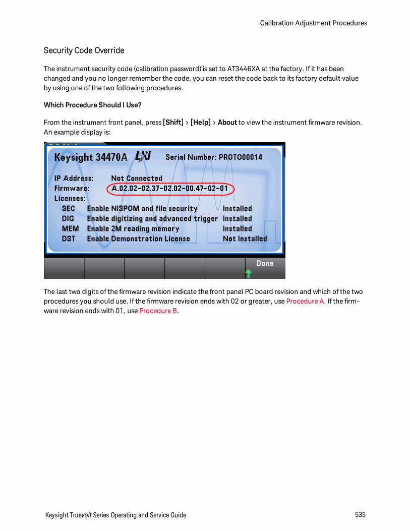
Security Code Override
The instrument security code (calibration password) is set to AT3446XA at the factory. If it has beenchanged and you no longer remember the code, you can reset the code back to its factory default valueby using one of the two following procedures.
Which Procedure Should I Use?
From the instrument front panel, press [Shift] > [Help] > About to view the instrument firmware revision.An example display is:
The last two digits of the firmware revision indicate the front panel PC board revision and which of the twoprocedures you should use. If the firmware revision ends with 02 or greater, use Procedure A. If the firm-ware revision ends with 01, use Procedure B.
Keysight Truevolt Series Operating and Service Guide 535
Calibration Adjustment Procedures
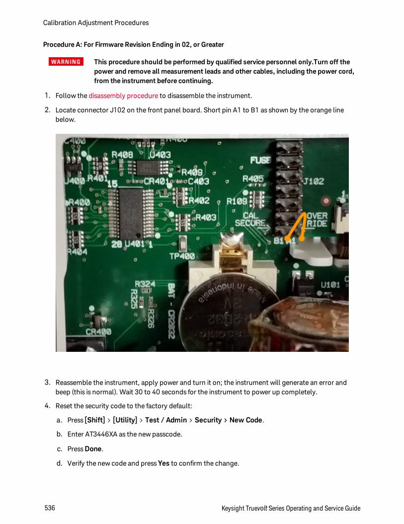
Procedure A: For Firmware Revision Ending in 02, or Greater
This procedure should be performed by qualified service personnel only.Turn off thepower and remove all measurement leads and other cables, including the power cord,from the instrument before continuing.
1. Follow the disassembly procedure to disassemble the instrument.
2. Locate connector J102 on the front panel board. Short pin A1 to B1 as shown by the orange linebelow.
3. Reassemble the instrument, apply power and turn it on; the instrument will generate an error andbeep (this is normal). Wait 30 to 40 seconds for the instrument to power up completely.
4. Reset the security code to the factory default:
a. Press [Shift] > [Utility] > Test / Admin > Security > New Code.
b. Enter AT3446XA as the new passcode.
c. Press Done.
d. Verify the new code and press Yes to confirm the change.
Calibration Adjustment Procedures
536 Keysight Truevolt Series Operating and Service Guide

5. Remove power, disassemble the instrument, and remove the short. Then reassemble the instrumentto complete the security code (calibration password) reset procedure.
Keysight Truevolt Series Operating and Service Guide 537
Calibration Adjustment Procedures
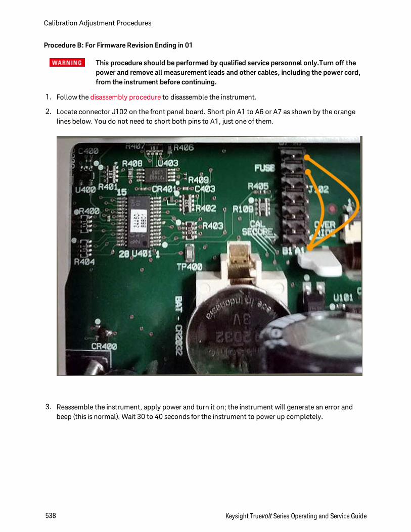
Procedure B: For Firmware Revision Ending in 01
This procedure should be performed by qualified service personnel only.Turn off thepower and remove all measurement leads and other cables, including the power cord,from the instrument before continuing.
1. Follow the disassembly procedure to disassemble the instrument.
2. Locate connector J102 on the front panel board. Short pin A1 to A6 or A7 as shown by the orangelines below. You do not need to short both pins to A1, just one of them.
3. Reassemble the instrument, apply power and turn it on; the instrument will generate an error andbeep (this is normal). Wait 30 to 40 seconds for the instrument to power up completely.
Calibration Adjustment Procedures
538 Keysight Truevolt Series Operating and Service Guide
4. Reset the security code to the factory default:
a. Press [Shift] > [Utility] > Test / Admin > Security > New Code.
b. Enter AT3446XA as the new passcode.
c. Press Done.
d. Verify the new code and press Yes to confirm the change.
5. Remove power, disassemble the instrument, and remove the short. Then reassemble the instrumentto complete the security code (calibration password) reset procedure.
Keysight Truevolt Series Operating and Service Guide 539
Calibration Adjustment Procedures
34460A and 34461A Calibration Procedures
The following calibration procedures apply only to the 34460A and 34461A DMMs. Perform the cal-ibration procedures in the order listed in this document. Use the arrow links at the bottom of every page togo to the next calibration procedure.
1. ADC and Zero Calibration Procedure
2. AC Voltage Low Freq Gain and Flatness Cal
3. AC Voltage Gain and Flatness Calibration
4. AC Current Gain and Flatness Calibration
5. AC Zero Calibration
6. Frequency Accuracy Calibration
7. DC Voltage Gain Calibration
8. Ohms Gain Calibration
9. DC Current Gain Calibration
10. AC Current 10 A Gain Calibration
11. DC Current 10 A Gain Calibration
12. Capacitance Offset Calibration (Optional)
13. Finishing Calibration
First Procedure
Calibration Adjustment Procedures
540 Keysight Truevolt Series Operating and Service Guide
ADC and Zero Calibration
Each time you perform a zero calibration, the instrument stores a new set of offset correction constants forevery measurement function and range. The instrument sequences through all required functions andranges automatically and stores new zero offset calibration constants. All offset corrections are determ-ined automatically. You may not correct a single range or function without re–entering ALL zero offset cor-rection constants automatically. This feature is intended to save calibration time and improve zerocalibration consistency.
Never turn off the instrument during Zero Calibration. This may cause ALL calibration memory to be lost.
ADC and DC Zero Calibration Procedure
This calibration procedure applies to all models (34460A/61A/65A/70A).
Be sure to allow the instrument to warm up and stabilize for 90 minutes before performing the calibration.
1. Follow the steps outlined below. Review Test Considerations before beginning this test.
2. This procedure uses a low–thermal shorting block installed on the input connectors.
For the 34461A/65A/70A, two shorting blocks are recommended; one on the front panel and one on therear panel. A single shorting block can be used with the 34460A.
3. Select the front panel input terminals. Install a shorting block on the front panel input terminals.
4. Select the ADC calibration mode ([Utility] > Test/Admin > Calibrate > Perform Cal > Perform ADCCal).
5. The display will show a message indicating that ADC calibration is in process. It will then display theresults of the ADC calibration. A Calibration Step Succeeded message indicates success; if the displayshows Calibration Step Failed, check the input value, range, function, and entered calibration valueand repeat the calibration step. Press Save Cal Values.
6. Select the DCV measurement function. Enter a calibration value of +0.
7. Press [Utility] > Test/Admin > Calibrate > Perform Cal > Perform Cal Step.
8. The Zero Calibration lasts approximately two minutes. A Calibration Step Succeeded message indic-ates success; if the display shows Calibration Step Failed, check the input value, range, function, andentered calibration value and repeat the calibration step.
9. Press Save Cal Values.
10. Select the rear input terminals. Install a shorting block rear-panel input terminals.
11. Repeat steps 4 through 9 for the rear input terminals.
12. Store the new ADC and Zero calibration constants (see Storing the Calibration Constants).
The following gain and flatness calibration procedures can be done using either the front or rear terminals(rear terminals not available on the 34460A). On the 34461A/65A/70A, make sure the Front/Rear switchmatches the terminals in use.
Keysight Truevolt Series Operating and Service Guide 541
Calibration Adjustment Procedures

Next Procedure
Calibration Adjustment Procedures
542 Keysight Truevolt Series Operating and Service Guide
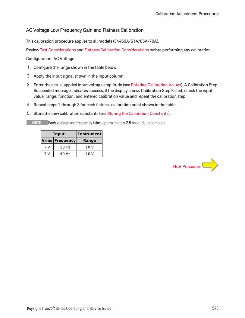
AC Voltage Low Frequency Gain and Flatness Calibration
This calibration procedure applies to all models (34460A/61A/65A/70A).
Review Test Considerations and Flatness Calibration Considerations before performing any calibration.
Configuration: AC Voltage
1. Configure the range shown in the table below.
2. Apply the input signal shown in the Input column.
3. Enter the actual applied input voltage amplitude (see Entering Calibration Values). A Calibration StepSucceeded message indicates success; if the display shows Calibration Step Failed, check the inputvalue, range, function, and entered calibration value and repeat the calibration step.
4. Repeat steps 1 through 3 for each flatness calibration point shown in the table.
5. Store the new calibration constants (see Storing the Calibration Constants).
Each voltage and frequency takes approximately 2.5 seconds to complete.
Input Instrument
Vrms Frequency Range
7 V 10 Hz 10 V
7 V 40 Hz 10 V
Next Procedure
Keysight Truevolt Series Operating and Service Guide 543
Calibration Adjustment Procedures
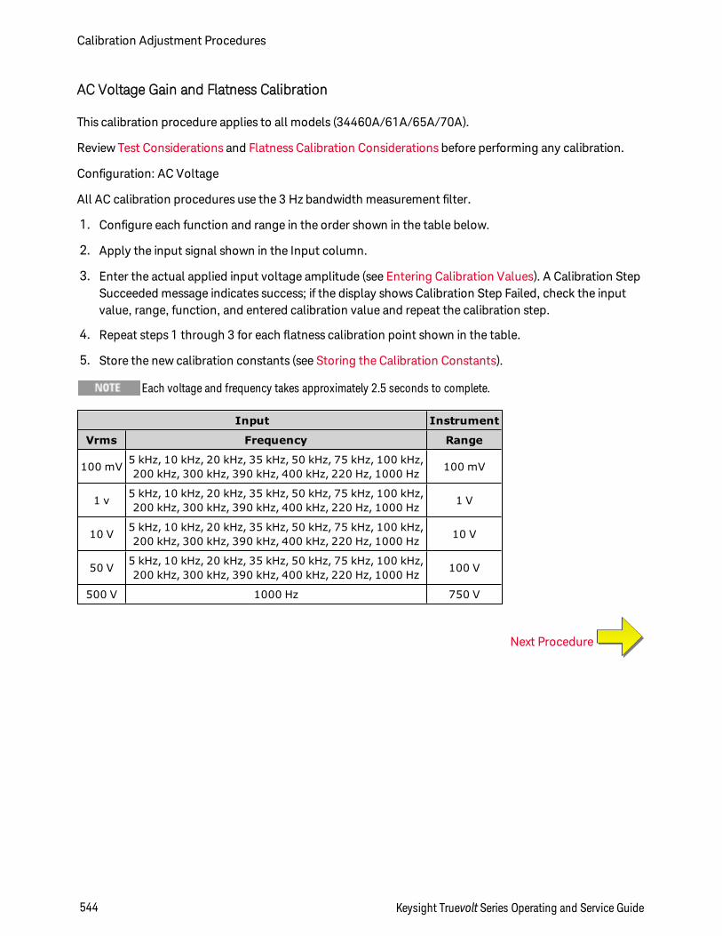
AC Voltage Gain and Flatness Calibration
This calibration procedure applies to all models (34460A/61A/65A/70A).
Review Test Considerations and Flatness Calibration Considerations before performing any calibration.
Configuration: AC Voltage
All AC calibration procedures use the 3 Hz bandwidth measurement filter.
1. Configure each function and range in the order shown in the table below.
2. Apply the input signal shown in the Input column.
3. Enter the actual applied input voltage amplitude (see Entering Calibration Values). A Calibration StepSucceeded message indicates success; if the display shows Calibration Step Failed, check the inputvalue, range, function, and entered calibration value and repeat the calibration step.
4. Repeat steps 1 through 3 for each flatness calibration point shown in the table.
5. Store the new calibration constants (see Storing the Calibration Constants).
Each voltage and frequency takes approximately 2.5 seconds to complete.
Input Instrument
Vrms Frequency Range
100 mV 5 kHz, 10 kHz, 20 kHz, 35 kHz, 50 kHz, 75 kHz, 100 kHz,200 kHz, 300 kHz, 390 kHz, 400 kHz, 220 Hz, 1000 Hz 100 mV
1 v 5 kHz, 10 kHz, 20 kHz, 35 kHz, 50 kHz, 75 kHz, 100 kHz,200 kHz, 300 kHz, 390 kHz, 400 kHz, 220 Hz, 1000 Hz 1 V
10 V 5 kHz, 10 kHz, 20 kHz, 35 kHz, 50 kHz, 75 kHz, 100 kHz,200 kHz, 300 kHz, 390 kHz, 400 kHz, 220 Hz, 1000 Hz 10 V
50 V 5 kHz, 10 kHz, 20 kHz, 35 kHz, 50 kHz, 75 kHz, 100 kHz,200 kHz, 300 kHz, 390 kHz, 400 kHz, 220 Hz, 1000 Hz 100 V
500 V 1000 Hz 750 V
Next Procedure
Calibration Adjustment Procedures
544 Keysight Truevolt Series Operating and Service Guide
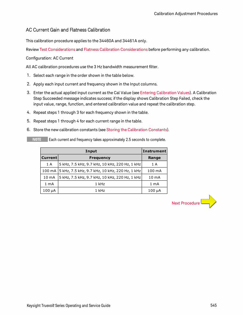
AC Current Gain and Flatness Calibration
This calibration procedure applies to the 34460A and 34461A only.
Review Test Considerations and Flatness Calibration Considerations before performing any calibration.
Configuration: AC Current
All AC calibration procedures use the 3 Hz bandwidth measurement filter.
1. Select each range in the order shown in the table below.
2. Apply each input current and frequency shown in the Input columns.
3. Enter the actual applied input current as the Cal Value (see Entering Calibration Values). A CalibrationStep Succeeded message indicates success; if the display shows Calibration Step Failed, check theinput value, range, function, and entered calibration value and repeat the calibration step.
4. Repeat steps 1 through 3 for each frequency shown in the table.
5. Repeat steps 1 through 4 for each current range in the table.
6. Store the new calibration constants (see Storing the Calibration Constants).
Each current and frequency takes approximately 2.5 seconds to complete.
Input Instrument
Current Frequency Range
1 A 5 kHz, 7.5 kHz, 9.7 kHz, 10 kHz, 220 Hz, 1 kHz 1 A
100 mA 5 kHz, 7.5 kHz, 9.7 kHz, 10 kHz, 220 Hz, 1 kHz 100 mA
10 mA 5 kHz, 7.5 kHz, 9.7 kHz, 10 kHz, 220 Hz, 1 kHz 10 mA
1 mA 1 kHz 1 mA
100 µA 1 kHz 100 µA
Next Procedure
Keysight Truevolt Series Operating and Service Guide 545
Calibration Adjustment Procedures
AC Zero Calibration
This calibration procedure applies to all models (34460A/61A/65A/70A).
Review Test Considerations before performing any calibration procedure.
Configuration: AC Voltage
1. Set the calibrator to 0.00 VAC.
2. Enter a calibration value of +0. (see Entering Calibration Values). A Calibration Step Succeeded mes-sage indicates success; if the display shows Calibration Step Failed, check the input value, range, func-tion, and entered calibration value and repeat the calibration step.
3. Store the new calibration constants (see Storing the Calibration Constants).
This calibration takes approximately 10 seconds to complete.
Next Procedure
Calibration Adjustment Procedures
546 Keysight Truevolt Series Operating and Service Guide
Frequency Accuracy Calibration
This calibration procedure applies to all models (34460A/61A/65A/70A).
Review Test Considerations and Gain Calibration Considerations before beginning this procedure.
Configuration: Frequency, 10 V range
The frequency accuracy of the Fluke 5720A is insufficient to calibrate the DMM. Its frequency output needsto be calibrated against a more accurate reference. The Keysight 33500B Series Function/Arbitrary Wave-form Generator is recommended for this calibration procedure.
1. Configure the instrument for frequency measurements at 10 V and 10 kHz, with 1 second gate time.
2. Apply a 10 kHz sine wave between 9 and 11 Vrms.
3. Enter the actual applied input frequency (see Entering Calibration Values). A Calibration Step Suc-ceeded message indicates success; if the display shows Calibration Step Failed, check the input value,range, function, and entered calibration value and repeat the calibration step.
4. Store the new calibration constants (see Storing the Calibration Constants).
This calibration takes approximately 1 second to complete.
Next Procedure
Keysight Truevolt Series Operating and Service Guide 547
Calibration Adjustment Procedures
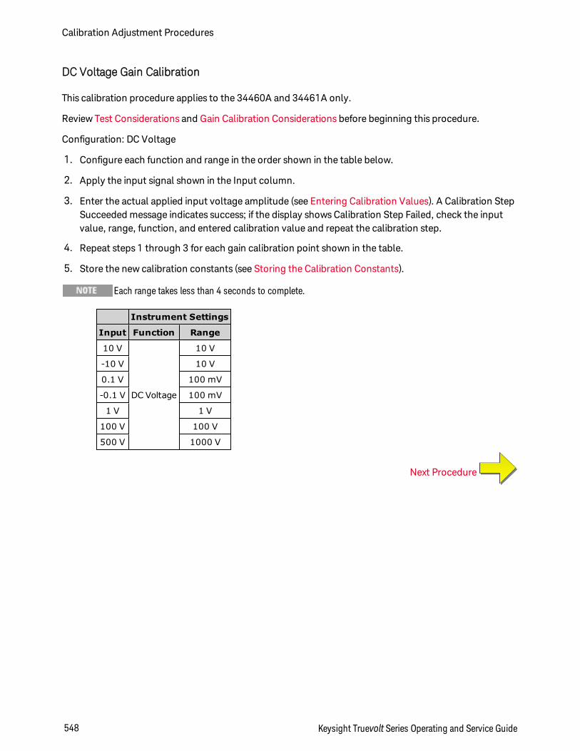
DC Voltage Gain Calibration
This calibration procedure applies to the 34460A and 34461A only.
Review Test Considerations and Gain Calibration Considerations before beginning this procedure.
Configuration: DC Voltage
1. Configure each function and range in the order shown in the table below.
2. Apply the input signal shown in the Input column.
3. Enter the actual applied input voltage amplitude (see Entering Calibration Values). A Calibration StepSucceeded message indicates success; if the display shows Calibration Step Failed, check the inputvalue, range, function, and entered calibration value and repeat the calibration step.
4. Repeat steps 1 through 3 for each gain calibration point shown in the table.
5. Store the new calibration constants (see Storing the Calibration Constants).
Each range takes less than 4 seconds to complete.
Instrument Settings
Input Function Range
10 V
DC Voltage
10 V
-10 V 10 V
0.1 V 100 mV
-0.1 V 100 mV
1 V 1 V
100 V 100 V
500 V 1000 V
Next Procedure
Calibration Adjustment Procedures
548 Keysight Truevolt Series Operating and Service Guide
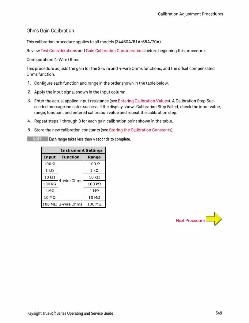
Ohms Gain Calibration
This calibration procedure applies to all models (34460A/61A/65A/70A).
Review Test Considerations and Gain Calibration Considerations before beginning this procedure.
Configuration: 4-Wire Ohms
This procedure adjusts the gain for the 2-wire and 4-wire Ohms functions, and the offset compensatedOhms function.
1. Configure each function and range in the order shown in the table below.
2. Apply the input signal shown in the Input column.
3. Enter the actual applied input resistance (see Entering Calibration Values). A Calibration Step Suc-ceeded message indicates success; if the display shows Calibration Step Failed, check the input value,range, function, and entered calibration value and repeat the calibration step.
4. Repeat steps 1 through 3 for each gain calibration point shown in the table.
5. Store the new calibration constants (see Storing the Calibration Constants).
Each range takes less than 4 seconds to complete.
Instrument Settings
Input Function Range
100 Ω
4-wire Ohms
100 Ω
1 kΩ 1 kΩ
10 kΩ 10 kΩ
100 kΩ 100 kΩ
1 MΩ 1 MΩ
10 MΩ 10 MΩ
100 MΩ 2-wire Ohms 100 MΩ
Next Procedure
Keysight Truevolt Series Operating and Service Guide 549
Calibration Adjustment Procedures
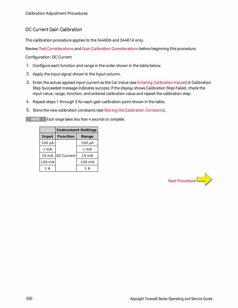
DC Current Gain Calibration
This calibration procedure applies to the 34460A and 34461A only.
Review Test Considerations and Gain Calibration Considerations before beginning this procedure.
Configuration: DC Current
1. Configure each function and range in the order shown in the table below.
2. Apply the input signal shown in the Input column.
3. Enter the actual applied input current as the Cal Value (see Entering Calibration Values).A CalibrationStep Succeeded message indicates success; if the display shows Calibration Step Failed, check theinput value, range, function, and entered calibration value and repeat the calibration step.
4. Repeat steps 1 through 3 for each gain calibration point shown in the table.
5. Store the new calibration constants (see Storing the Calibration Constants).
Each range takes less than 4 seconds to complete.
Instrument Settings
Input Function Range
100 µA
DC Current
100 µA
1 mA 1 mA
10 mA 10 mA
100 mA 100 mA
1 A 1 A
Next Procedure
Calibration Adjustment Procedures
550 Keysight Truevolt Series Operating and Service Guide
AC Current 10 A Gain Calibration
This calibration procedure applies to the 34461A, 34465A, and 34470A only (not applicable to the34460A).
Review Test Considerations and Flatness Calibration Considerations before performing any calibration.
Configuration: AC Current
All AC calibration procedures use the 3 Hz bandwidth measurement filter.
1. Select the 10 A range.
2. Apply the 5 A input signal at 1000 Hz.
3. Enter the actual applied input current as the Cal Value (see Entering Calibration Values).A CalibrationStep Succeeded message indicates success; if the display shows Calibration Step Failed, check theinput value, range, function, and entered calibration value and repeat the calibration step.
4. Store the new calibration constants (see Storing the Calibration Constants).
This calibration takes approximately 2.5 seconds to complete.
Next Procedure
Keysight Truevolt Series Operating and Service Guide 551
Calibration Adjustment Procedures

DC Current 10 A Gain Calibration
This calibration procedure applies to the 34461A, 34465A, and 34470A only (not applicable to the34460A).
Review Test Considerations and Flatness Calibration Considerations before performing any calibration.
Configuration: DC Current
1. Configure the 10 A range and set the integration time to 100 PLC.
2. Apply the 5 A input.
3. Enter the actual applied input current as the Cal Value (see Entering Calibration Values).A CalibrationStep Succeeded message indicates success; if the display shows Calibration Step Failed, check theinput value, range, function, and entered calibration value and repeat the calibration step.
4. Store the new calibration constants (see Storing the Calibration Constants).
This calibration takes less than 4 seconds to complete.
Next Procedure
Calibration Adjustment Procedures
552 Keysight Truevolt Series Operating and Service Guide

Capacitance Offset Calibration (Optional)
This calibration procedure applies to all models (34460A/61A/65A/70A).
This calibration is normally not required. It compensates for residual capacitance offset which is typicallyless than a few pF. In normal use, any residual offset will be overridden by the null function (null also cor-rects for cable capacitance), and the null function is required to achieve the multimeter’s capacitance spe-cification.
Configuration: Capacitance
1. Remove all connections from the instrument's front terminals.
2. Select the front terminals.
3. Enter a calibration value of +0 (see Entering Calibration Values). A Calibration Step Succeeded mes-sage indicates success; if the display shows Calibration Step Failed, check the input value, range, func-tion, and entered calibration value and repeat the calibration step.
4. Repeat steps 1 through 3 for the instrument's rear terminals (not applicable to the 34460A).
5. Store the new calibration constants (see Storing the Calibration Constants).
Next Procedure
Keysight Truevolt Series Operating and Service Guide 553
Calibration Adjustment Procedures
Finishing Calibration
To finish calibrating your instrument:
1. Remove all shorting blocks and connections from the instrument.
2. Reset the calibration message.
3. Secure the instrument with the calibration password.
4. Record the new calibration count.
5. Perform the performance verification tests to verify the calibration.
Calibration Adjustment Procedures
554 Keysight Truevolt Series Operating and Service Guide
34465A and 34470A Calibration Procedures
The following calibration procedures apply only to the 34465A and 34470A DMMs. Perform the cal-ibration procedures in the order listed in this document. Use the arrow links at the bottom of every page togo to the next calibration procedure.
1. ADC and Zero Calibration
2. AC Voltage Low Frequency Gain and Flatness Calibration
3. AC Voltage Gain and Flatness Calibration
4. AC Current Gain and Flatness Calibration
5. AC Zero Calibration
6. Frequency Accuracy Calibration
7. DC Voltage Gain Calibration
8. Ohms Gain Calibration
9. DC Current Gain Calibration
10. AC Current 10 A Gain Calibration
11. DC Current 10 A Gain Calibration
12. DC High Voltage Gain Calibration
13. Capacitance Offset Calibration (Optional)
14. Finishing Calibration
First Procedure
Keysight Truevolt Series Operating and Service Guide 555
Calibration Adjustment Procedures
ADC and Zero Calibration
Each time you perform a zero calibration, the instrument stores a new set of offset correction constants forevery measurement function and range. The instrument sequences through all required functions andranges automatically and stores new zero offset calibration constants. All offset corrections are determ-ined automatically. You may not correct a single range or function without re–entering ALL zero offset cor-rection constants automatically. This feature is intended to save calibration time and improve zerocalibration consistency.
Never turn off the instrument during Zero Calibration. This may cause ALL calibration memory to be lost.
ADC and DC Zero Calibration Procedure
This calibration procedure applies to all models (34460A/61A/65A/70A).
Be sure to allow the instrument to warm up and stabilize for 90 minutes before performing the calibration.
1. Follow the steps outlined below. Review Test Considerations before beginning this test.
2. This procedure uses a low–thermal shorting block installed on the input connectors.
For the 34461A/65A/70A, two shorting blocks are recommended; one on the front panel and one on therear panel. A single shorting block can be used with the 34460A.
3. Select the front panel input terminals. Install a shorting block on the front panel input terminals.
4. Select the ADC calibration mode ([Utility] > Test/Admin > Calibrate > Perform Cal > Perform ADCCal).
5. The display will show a message indicating that ADC calibration is in process. It will then display theresults of the ADC calibration. A Calibration Step Succeeded message indicates success; if the displayshows Calibration Step Failed, check the input value, range, function, and entered calibration valueand repeat the calibration step. Press Save Cal Values.
6. Select the DCV measurement function. Enter a calibration value of +0.
7. Press [Utility] > Test/Admin > Calibrate > Perform Cal > Perform Cal Step.
8. The Zero Calibration lasts approximately two minutes. A Calibration Step Succeeded message indic-ates success; if the display shows Calibration Step Failed, check the input value, range, function, andentered calibration value and repeat the calibration step.
9. Press Save Cal Values.
10. Select the rear input terminals. Install a shorting block rear-panel input terminals.
11. Repeat steps 4 through 9 for the rear input terminals.
12. Store the new ADC and Zero calibration constants (see Storing the Calibration Constants).
The following gain and flatness calibration procedures can be done using either the front or rear terminals(rear terminals not available on the 34460A). On the 34461A/65A/70A, make sure the Front/Rear switchmatches the terminals in use.
Calibration Adjustment Procedures
556 Keysight Truevolt Series Operating and Service Guide

Next Procedure
Keysight Truevolt Series Operating and Service Guide 557
Calibration Adjustment Procedures
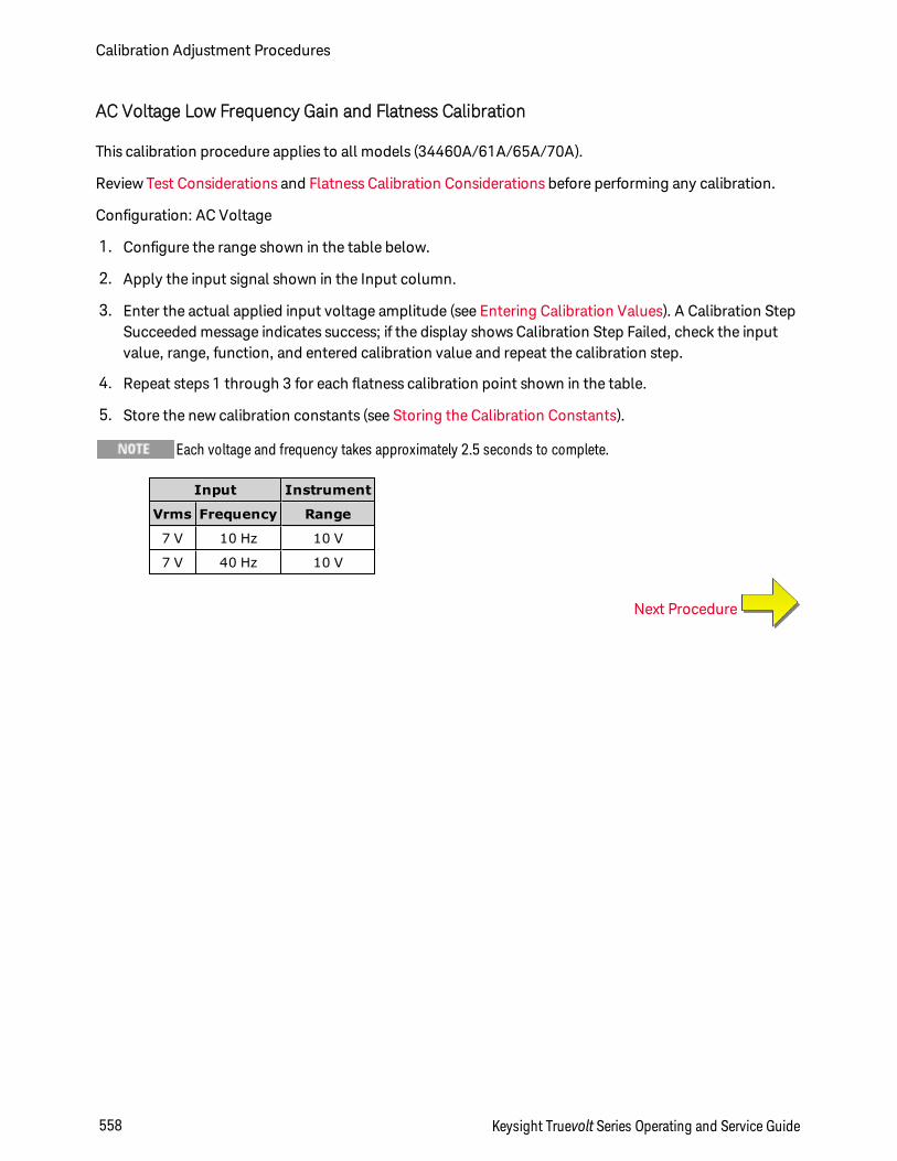
AC Voltage Low Frequency Gain and Flatness Calibration
This calibration procedure applies to all models (34460A/61A/65A/70A).
Review Test Considerations and Flatness Calibration Considerations before performing any calibration.
Configuration: AC Voltage
1. Configure the range shown in the table below.
2. Apply the input signal shown in the Input column.
3. Enter the actual applied input voltage amplitude (see Entering Calibration Values). A Calibration StepSucceeded message indicates success; if the display shows Calibration Step Failed, check the inputvalue, range, function, and entered calibration value and repeat the calibration step.
4. Repeat steps 1 through 3 for each flatness calibration point shown in the table.
5. Store the new calibration constants (see Storing the Calibration Constants).
Each voltage and frequency takes approximately 2.5 seconds to complete.
Input Instrument
Vrms Frequency Range
7 V 10 Hz 10 V
7 V 40 Hz 10 V
Next Procedure
Calibration Adjustment Procedures
558 Keysight Truevolt Series Operating and Service Guide
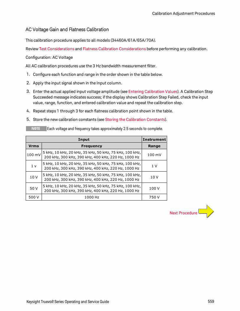
AC Voltage Gain and Flatness Calibration
This calibration procedure applies to all models (34460A/61A/65A/70A).
Review Test Considerations and Flatness Calibration Considerations before performing any calibration.
Configuration: AC Voltage
All AC calibration procedures use the 3 Hz bandwidth measurement filter.
1. Configure each function and range in the order shown in the table below.
2. Apply the input signal shown in the Input column.
3. Enter the actual applied input voltage amplitude (see Entering Calibration Values). A Calibration StepSucceeded message indicates success; if the display shows Calibration Step Failed, check the inputvalue, range, function, and entered calibration value and repeat the calibration step.
4. Repeat steps 1 through 3 for each flatness calibration point shown in the table.
5. Store the new calibration constants (see Storing the Calibration Constants).
Each voltage and frequency takes approximately 2.5 seconds to complete.
Input Instrument
Vrms Frequency Range
100 mV 5 kHz, 10 kHz, 20 kHz, 35 kHz, 50 kHz, 75 kHz, 100 kHz,200 kHz, 300 kHz, 390 kHz, 400 kHz, 220 Hz, 1000 Hz 100 mV
1 v 5 kHz, 10 kHz, 20 kHz, 35 kHz, 50 kHz, 75 kHz, 100 kHz,200 kHz, 300 kHz, 390 kHz, 400 kHz, 220 Hz, 1000 Hz 1 V
10 V 5 kHz, 10 kHz, 20 kHz, 35 kHz, 50 kHz, 75 kHz, 100 kHz,200 kHz, 300 kHz, 390 kHz, 400 kHz, 220 Hz, 1000 Hz 10 V
50 V 5 kHz, 10 kHz, 20 kHz, 35 kHz, 50 kHz, 75 kHz, 100 kHz,200 kHz, 300 kHz, 390 kHz, 400 kHz, 220 Hz, 1000 Hz 100 V
500 V 1000 Hz 750 V
Next Procedure
Keysight Truevolt Series Operating and Service Guide 559
Calibration Adjustment Procedures
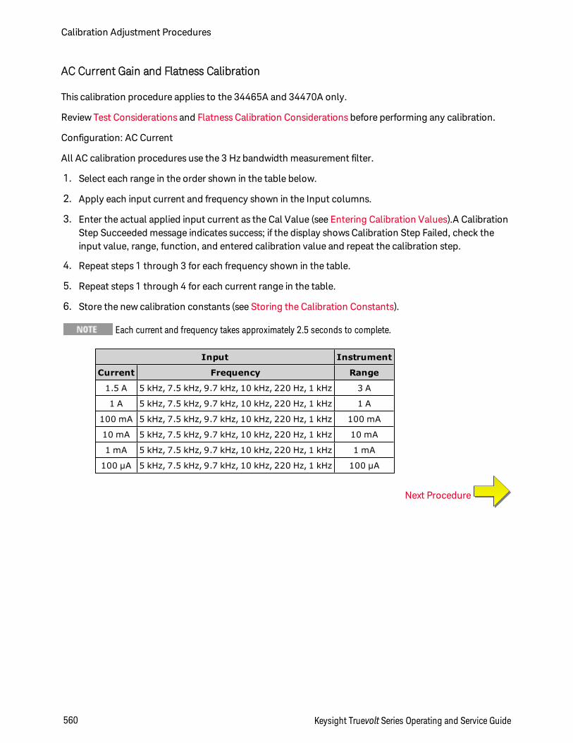
AC Current Gain and Flatness Calibration
This calibration procedure applies to the 34465A and 34470A only.
Review Test Considerations and Flatness Calibration Considerations before performing any calibration.
Configuration: AC Current
All AC calibration procedures use the 3 Hz bandwidth measurement filter.
1. Select each range in the order shown in the table below.
2. Apply each input current and frequency shown in the Input columns.
3. Enter the actual applied input current as the Cal Value (see Entering Calibration Values).A CalibrationStep Succeeded message indicates success; if the display shows Calibration Step Failed, check theinput value, range, function, and entered calibration value and repeat the calibration step.
4. Repeat steps 1 through 3 for each frequency shown in the table.
5. Repeat steps 1 through 4 for each current range in the table.
6. Store the new calibration constants (see Storing the Calibration Constants).
Each current and frequency takes approximately 2.5 seconds to complete.
Input Instrument
Current Frequency Range
1.5 A 5 kHz, 7.5 kHz, 9.7 kHz, 10 kHz, 220 Hz, 1 kHz 3 A
1 A 5 kHz, 7.5 kHz, 9.7 kHz, 10 kHz, 220 Hz, 1 kHz 1 A
100 mA 5 kHz, 7.5 kHz, 9.7 kHz, 10 kHz, 220 Hz, 1 kHz 100 mA
10 mA 5 kHz, 7.5 kHz, 9.7 kHz, 10 kHz, 220 Hz, 1 kHz 10 mA
1 mA 5 kHz, 7.5 kHz, 9.7 kHz, 10 kHz, 220 Hz, 1 kHz 1 mA
100 µA 5 kHz, 7.5 kHz, 9.7 kHz, 10 kHz, 220 Hz, 1 kHz 100 µA
Next Procedure
Calibration Adjustment Procedures
560 Keysight Truevolt Series Operating and Service Guide
AC Zero Calibration
This calibration procedure applies to all models (34460A/61A/65A/70A).
Review Test Considerations before performing any calibration procedure.
Configuration: AC Voltage
1. Set the calibrator to 0.00 VAC.
2. Enter a calibration value of +0. (see Entering Calibration Values). A Calibration Step Succeeded mes-sage indicates success; if the display shows Calibration Step Failed, check the input value, range, func-tion, and entered calibration value and repeat the calibration step.
3. Store the new calibration constants (see Storing the Calibration Constants).
This calibration takes approximately 10 seconds to complete.
Next Procedure
Keysight Truevolt Series Operating and Service Guide 561
Calibration Adjustment Procedures
Frequency Accuracy Calibration
This calibration procedure applies to all models (34460A/61A/65A/70A).
Review Test Considerations and Gain Calibration Considerations before beginning this procedure.
Configuration: Frequency, 10 V range
The frequency accuracy of the Fluke 5720A is insufficient to calibrate the DMM. Its frequency output needsto be calibrated against a more accurate reference. The Keysight 33500B Series Function/Arbitrary Wave-form Generator is recommended for this calibration procedure.
1. Configure the instrument for frequency measurements at 10 V and 10 kHz, with 1 second gate time.
2. Apply a 10 kHz sine wave between 9 and 11 Vrms.
3. Enter the actual applied input frequency (see Entering Calibration Values). A Calibration Step Suc-ceeded message indicates success; if the display shows Calibration Step Failed, check the input value,range, function, and entered calibration value and repeat the calibration step.
4. Store the new calibration constants (see Storing the Calibration Constants).
This calibration takes approximately 1 second to complete.
Next Procedure
Calibration Adjustment Procedures
562 Keysight Truevolt Series Operating and Service Guide
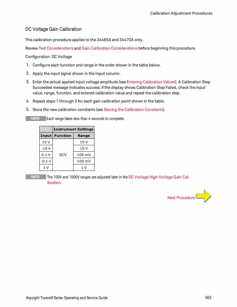
DC Voltage Gain Calibration
This calibration procedure applies to the 34465A and 34470A only.
Review Test Considerations and Gain Calibration Considerations before beginning this procedure.
Configuration: DC Voltage
1. Configure each function and range in the order shown in the table below.
2. Apply the input signal shown in the Input column.
3. Enter the actual applied input voltage amplitude (see Entering Calibration Values). A Calibration StepSucceeded message indicates success; if the display shows Calibration Step Failed, check the inputvalue, range, function, and entered calibration value and repeat the calibration step.
4. Repeat steps 1 through 3 for each gain calibration point shown in the table.
5. Store the new calibration constants (see Storing the Calibration Constants).
Each range takes less than 4 seconds to complete.
Instrument Settings
Input Function Range
10 V
DCV
10 V
-10 V 10 V
0.1 V 100 mV
-0.1 V 100 mV
1 V 1 V
The 100V and 1000V ranges are adjusted later in theDC Voltage High Voltage Gain Cal-ibration.
Next Procedure
Keysight Truevolt Series Operating and Service Guide 563
Calibration Adjustment Procedures
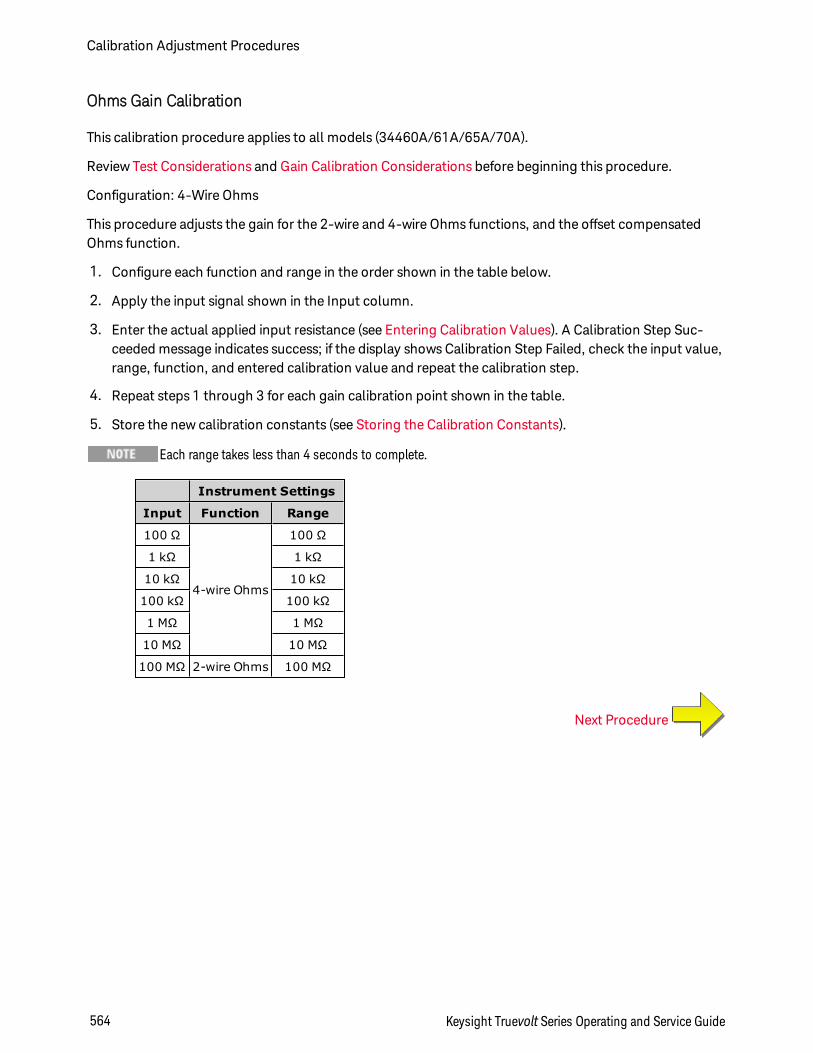
Ohms Gain Calibration
This calibration procedure applies to all models (34460A/61A/65A/70A).
Review Test Considerations and Gain Calibration Considerations before beginning this procedure.
Configuration: 4-Wire Ohms
This procedure adjusts the gain for the 2-wire and 4-wire Ohms functions, and the offset compensatedOhms function.
1. Configure each function and range in the order shown in the table below.
2. Apply the input signal shown in the Input column.
3. Enter the actual applied input resistance (see Entering Calibration Values). A Calibration Step Suc-ceeded message indicates success; if the display shows Calibration Step Failed, check the input value,range, function, and entered calibration value and repeat the calibration step.
4. Repeat steps 1 through 3 for each gain calibration point shown in the table.
5. Store the new calibration constants (see Storing the Calibration Constants).
Each range takes less than 4 seconds to complete.
Instrument Settings
Input Function Range
100 Ω
4-wire Ohms
100 Ω
1 kΩ 1 kΩ
10 kΩ 10 kΩ
100 kΩ 100 kΩ
1 MΩ 1 MΩ
10 MΩ 10 MΩ
100 MΩ 2-wire Ohms 100 MΩ
Next Procedure
Calibration Adjustment Procedures
564 Keysight Truevolt Series Operating and Service Guide
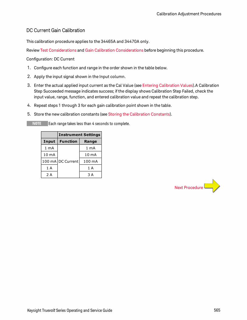
DC Current Gain Calibration
This calibration procedure applies to the 34465A and 34470A only.
Review Test Considerations and Gain Calibration Considerations before beginning this procedure.
Configuration: DC Current
1. Configure each function and range in the order shown in the table below.
2. Apply the input signal shown in the Input column.
3. Enter the actual applied input current as the Cal Value (see Entering Calibration Values).A CalibrationStep Succeeded message indicates success; if the display shows Calibration Step Failed, check theinput value, range, function, and entered calibration value and repeat the calibration step.
4. Repeat steps 1 through 3 for each gain calibration point shown in the table.
5. Store the new calibration constants (see Storing the Calibration Constants).
Each range takes less than 4 seconds to complete.
Instrument Settings
Input Function Range
1 mA
DC Current
1 mA
10 mA 10 mA
100 mA 100 mA
1 A 1 A
2 A 3 A
Next Procedure
Keysight Truevolt Series Operating and Service Guide 565
Calibration Adjustment Procedures
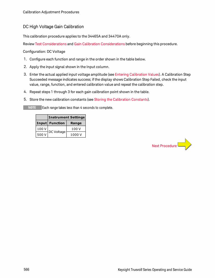
DC High Voltage Gain Calibration
This calibration procedure applies to the 34465A and 34470A only.
Review Test Considerations and Gain Calibration Considerations before beginning this procedure.
Configuration: DC Voltage
1. Configure each function and range in the order shown in the table below.
2. Apply the input signal shown in the Input column.
3. Enter the actual applied input voltage amplitude (see Entering Calibration Values). A Calibration StepSucceeded message indicates success; if the display shows Calibration Step Failed, check the inputvalue, range, function, and entered calibration value and repeat the calibration step.
4. Repeat steps 1 through 3 for each gain calibration point shown in the table.
5. Store the new calibration constants (see Storing the Calibration Constants).
Each range takes less than 4 seconds to complete.
Instrument Settings
Input Function Range
100 VDC Voltage
100 V
500 V 1000 V
Next Procedure
Calibration Adjustment Procedures
566 Keysight Truevolt Series Operating and Service Guide
AC Current 10 A Gain Calibration
This calibration procedure applies to the 34461A, 34465A, and 34470A only (not applicable to the34460A).
Review Test Considerations and Flatness Calibration Considerations before performing any calibration.
Configuration: AC Current
All AC calibration procedures use the 3 Hz bandwidth measurement filter.
1. Select the 10 A range.
2. Apply the 5 A input signal at 1000 Hz.
3. Enter the actual applied input current as the Cal Value (see Entering Calibration Values).A CalibrationStep Succeeded message indicates success; if the display shows Calibration Step Failed, check theinput value, range, function, and entered calibration value and repeat the calibration step.
4. Store the new calibration constants (see Storing the Calibration Constants).
This calibration takes approximately 2.5 seconds to complete.
Next Procedure
Keysight Truevolt Series Operating and Service Guide 567
Calibration Adjustment Procedures
DC Current 10 A Gain Calibration
This calibration procedure applies to the 34461A, 34465A, and 34470A only (not applicable to the34460A).
Review Test Considerations and Flatness Calibration Considerations before performing any calibration.
Configuration: DC Current
1. Configure the 10 A range and set the integration time to 100 PLC.
2. Apply the 5 A input.
3. Enter the actual applied input current as the Cal Value (see Entering Calibration Values).A CalibrationStep Succeeded message indicates success; if the display shows Calibration Step Failed, check theinput value, range, function, and entered calibration value and repeat the calibration step.
4. Store the new calibration constants (see Storing the Calibration Constants).
This calibration takes less than 4 seconds to complete.
Next Procedure
Calibration Adjustment Procedures
568 Keysight Truevolt Series Operating and Service Guide
Capacitance Offset Calibration (Optional)
This calibration procedure applies to all models (34460A/61A/65A/70A).
This calibration is normally not required. It compensates for residual capacitance offset which is typicallyless than a few pF. In normal use, any residual offset will be overridden by the null function (null also cor-rects for cable capacitance), and the null function is required to achieve the multimeter’s capacitance spe-cification.
Configuration: Capacitance
1. Remove all connections from the instrument's front terminals.
2. Select the front terminals.
3. Enter a calibration value of +0 (see Entering Calibration Values). A Calibration Step Succeeded mes-sage indicates success; if the display shows Calibration Step Failed, check the input value, range, func-tion, and entered calibration value and repeat the calibration step.
4. Repeat steps 1 through 3 for the instrument's rear terminals (not applicable to the 34460A).
5. Store the new calibration constants (see Storing the Calibration Constants).
Next Procedure
Keysight Truevolt Series Operating and Service Guide 569
Calibration Adjustment Procedures

Finishing Calibration
To finish calibrating your instrument:
1. Remove all shorting blocks and connections from the instrument.
2. Reset the calibration message.
3. Secure the instrument with the calibration password.
4. Record the new calibration count.
5. Perform the performance verification tests to verify the calibration.
Calibration Adjustment Procedures
570 Keysight Truevolt Series Operating and Service Guide
Index
*
*CAL? 266
*CLS 266
*ESE 267
*ESR? 268
*IDN? 269
*LRN? 271
*OPC 271
*OPC? 272
*OPT? 272
*PSC 273
*PSC? 273
*RST 274
*SAV 273
*SRE 274
*STB? 275
*TRG 275
*TST? 276
*WAI 276
2
2-wire measurements 346-347, 352
2-wire Resistance 250, 313, 353-355
2-Wire Resistance 66
2-wire RTD 251
2-Wire vs. 4-Wire Measurements 172
3
34460A and 34461A adjustments 540
34461A adjustments 540
34465A and 34470A Adjustments 555
34470A adjustments 555
34470A and 34465A adjustments 555
4
4-wire Resistance 250, 313, 353-355
4-Wire Resistance 66
4-wire RTD 251, 361
A
ABORt 201
About Digitizing Mode 178
AC 247, 252, 284, 289, 320-327, 373-379
AC Current 64, 313, 325-326
AC current flatness 545, 560
AC Current Measurement Errors (BurdenVoltage) 190
AC current verification 516, 521
AC Voltage 60, 252, 313, 377-378
AC voltage verification 516
AC Zero Calibration 546, 561
ACALibration 393-394
ACI 64
acquiring readings 95
ACV 60
Keysight Truevolt Series Operating and Service Guide 571
ADC 237, 541, 556
ADDRess 407
ADJust 368
adjustments 523, 529-530, 541, 554,556, 570
Admin 147
Aliasing 177
ALL 208, 218, 230, 238, 293, 423
APERture 327, 337, 346-347, 359, 379
APERture Enabled 380
APERture ENABled 328, 359
ASCII String Parameters 198
AUTO 197, 220, 226, 245, 250, 252, 254,282, 299-300, 316, 323, 325-326,332, 339, 343, 351, 354, 357, 362,371, 376, 378, 381, 385, 430
Autocal command 266
Autocalibration 139
Automatic input impedance 381
automatic trigger delays 456
Autorange 245, 250, 252, 254, 282, 354,378
Autozero 310, 332, 357, 385
Autozero On/Off 173
AVERage 212, 230, 232
Average, moving 234-235
B
BANDwidth 320, 373
Bar Meter 121
battery 492
BEEPer 394-395
BMP 263
Boolean Parameters 198
BORDer 261
Burden Voltage 190
BUS 198, 433
C
CALCulate 212, 214-216, 218-228, 230,232, 234-235
AVERage Subsystem 229
histogram 218-221
HISTogram Subsystem 217
LIMit Subsystem 213
SCALe Subsystem 222
scaling 228
smoothing 234-235
TCHart
STATe 236
CALCulate Subsystem Introduction 210
calibration 506, 510, 515-516, 521, 523-524, 528-533, 541, 545, 554, 556,560, 570
CALibration 237-242, 445
calibration adjustments 530
calibration count 533
Calibration Errors 460
572 Keysight Truevolt Series Operating and Service Guide
CALibration Subsystem 237
Capacitance 76
CAPacitance 245, 282, 314-318
Capacitance MeasurementConsiderations 176
Capacitance Offset Calibration(Optional) 553, 569
Capacitance Theory 175
Capacitance Verification (Optional Veri-fication Test) 522
Carrying Handle 40
CATalog 293, 422
CD-ROM 194
CDIRectory 294
celsius 367, 369
Characteristics 327, 346, 359, 379
Chart 124
CHECk 367
CLEar 219
CLEAr 212, 214, 232, 260
CLICk 395
CLS 197, 266
CODE 239
Command Errors 460
Command Quick Reference 434
Command Separators 196
Command Summary 243, 261, 280, 306
Commands by Subsystem 199
Common Mode Errors 191
COMMunicate 406-415, 417
CONDition 389-390
CONFigure 245-252, 254
Configure I/O 144
CONFigure Subsystem 243
CONFigure? 245
configuring remote interface 27, 32
contacting Keysight 35
Continuity 77
CONTinuity 246, 283, 313
CONTinuous 333
Continuous Mode 47
CONTrol 408
COPY 294
count 533
COUNt 219, 230, 238, 306-307, 401,424, 428
CSEParator 303
CURRent 247, 284, 313, 320-333
current fuse replacement 494
current verification 516
Current, DC 62
D
DATA 215, 218, 256-258, 261, 263, 303,305
Data Log and Digitize Mode Default Set-tings 48
Keysight Truevolt Series Operating and Service Guide 573
Data Log Mode 47, 81, 181
Data Log Mode Features 181
Data Logging 81
Data Logging Local/RemoteInteraction 180, 186
Data Logging, Trend Chart 127
DATA Subsystem 256
DATA2 334
DATE 396
DATE? 239, 393
DB 222
dB Scaling 103
DBM 223
dBm Scaling 103
DC 247, 254, 284, 289-290, 293, 321-332, 374, 375-376, 379-385
DC Current 62, 171, 313, 330, 332
DC Current Gain Calibration 550, 565
DC current verification 521
DC measurements 455
DC Voltage 57, 313, 381-383, 385
DC voltage measurements 57
DCI 62
DCV measurements 57
DCV tutorial 57
DEFault 196
Default Settings 243, 280, 474
DELay 308, 429-430
Delay, trigger 97
delays, trigger 456
DELete 295, 423
DESCription 423
DESired 278
Device-Specific Errors 460
Device Clear 199, 408
DHCP 408
Digitize Mode 47, 86
Digitizing 86
Digitizing Local/Remote Interaction 180,186
Digitizing Measurements 177
Digitizing Mode 178
Digitizing, Trend Chart 127
Diode 78
DIODe 248, 285, 313
disassembly 488
Discrete Parameters 198
DISPlay 198, 259-260
Display Bar Meter 121
Display Histogram 133
Display Introduction 114
Display Number 116
DISPlay Subsystem Introduction 259
Display Trend Chart (ContinuousMode) 124
Distributor installed options 26
574 Keysight Truevolt Series Operating and Service Guide
dmm 367, 369
DNS 409
DOMain 409
DOWNload 303
Drivers 194
E
ENABle 277, 389, 391, 406, 418
End-Or-Identify 197
ERRor 397, 424
Error Messages 460
Error Queue 460
Errors in High ResistanceMeasurements 166
ESE 197, 267
ESR? 268
Estimating High–Frequency (Out–of–Band) Error 169
EVENt 257-258, 390-391
Event Status Enable 273
Execute SAMPle 310
Execution Error 460
Ext Trig BNC 433
EXTernal 198, 433
F
Factory installed options 26
Factory Reset 261, 274, 308-309, 311,314-315, 327, 346, 359, 379, 396,403, 474
Factory Settings 474
FAST 234, 333
features 46
FETCh? 202
Files, Manage 142
finishing adustments 554, 570
firmware update 34
flatness 545, 560
flatness adjustments 529
flatness calibration 545, 560
FNAMe 303
FORMat 261, 263, 303-304
FORMat Subsystem 261
Frequency 79
FREQuency 249, 286, 313, 337-344
Frequency and Period MeasurementErrors Frequency and Period Meas-urement Errors Frequency andPeriod Measurement Errors 171
frequency gain verification 515
FRESistance 250, 287, 313, 346-356
FRONt 207
Front and rear terminals 207
front panel 24
Front panel keys 50
Front panel menu reference 50
FRTD 251, 288, 365-366
FTHermistor 370
Keysight Truevolt Series Operating and Service Guide 575
FUNCtion 223, 313
functions 46
fuse replacement 494
G
GAIN 224-225
gain adjustment 528-529
gain verification 510, 515
GATeway 410
GPIB 194, 407
GPIB option 497
Ground Loops, Noise 164
H
Handle 40
HCOPy 263
HCOPy Subsystem 263
Help 41
HELP 398
Help system 41
HI-Z 381
High-Voltage Self-Heating Errors 190
High–Frequency (Out–of–Band)Error 169
High–Frequency Signal Content and TrueRMS Accuracy 168
High–Speed AC Measurements 173
High–Speed DC and Resistance Meas-urements 174
High Resistance Measurement Errors 166
Histogram 133
HISTogram 218-221
HNAMe 278
hold readings 100
HOST 418
HOSTname 411
How Sample Rate/Interval isDetermined 193
HP34401A 399
I
I/O Configuration 144
LAN 423, 425
IDENtify 277, 399
IDN? 269
IEEE 488.2 Commands 197, 271
IEEE 488.2 Common Commands 264
IMMediate 198, 203, 212, 214, 232, 394,402, 433
IMPedance 381
INFormation 304
INITiate 203
Input impedance 381
Input terminal measurement limits 18
INSTall 425
Instrument Errors 460
Instrument Preset 261, 308, 311, 396,403, 474
576 Keysight Truevolt Series Operating and Service Guide
integration table 455
integration time 455
INTernal 430, 433
internal DMM 367
internal fuse replacement 494
Interval and Sample Rate 193
Introduction to instrument 23
Introduction to the SCPI Language 195
IPADdress 412
K
Keysight 35
Keysight IO Libraries Suite 194
L
LABel 400
LAN 408-415, 417
configuring 278
LAN configuration 27
LAN Configuration 32
LAST 256
Leakage Current Errors 192
Learn String 271
LEVel 430
Level Triggering 178
Level Triggering Details 91, 187
LFRequency 400
LICense 422-425
LIMit 214-216, 442
Limits 110
Limits, measurement 18
Line Noise Voltages, Rejecting 163
LOAD 298-299
Loading Errors (AC volts) 189
Loading Errors (DC Voltage) 162
LOCal 400
Local key 259
Local/Remote Interaction 180, 186
LOCK 420-421
Low-Power 353, 365-366
Low–Level Measurement Errors 191
LOWer 215, 220, 340
LPOWer 353, 366
LRN 271
LXI 277-279
LXI Subsystem 277
M
MAC 412
Magnetic Loops, Noise 163
Making High–Speed ACMeasurements 173
Making High–Speed DC and ResistanceMeasurements 174
Manage Files 142
Master Summary 275
Keysight Truevolt Series Operating and Service Guide 577
Math Functions 227
Math Introduction 101
Math Limits 110
Math Null 102
Math Scaling 105
Math Smoothing 108
Math Statistics 109
MAXimum 196, 230
Maximum limits 18
MDIRectory 294
MDNS 277-278
MEASure 282-290, 434
MEASure Subsystem 280
Measurement Considerations 160
Measurement Considerations, Capa-citance 176
Measurement limits 18
Measurement Tutorial 159
Measurements 56
Measurements Below Full Scale 190
MEDium 234
Menu reference 50
Minimizing Power Dissipation Effects 166
MINimum 196, 230
MMEMory 293-295, 298-300, 303-305,396, 403
MMEMory Subsystem - Data TransferCommands 301
MMEMory Subsystem - General PurposeFile Management 291
MMEMory Subsystem - STATe andPREFerence Files 296
MODE 333
Models and options 26
MOVE 295
Mx-B Scaling 227
N
NAME 420
NEGative 204, 432
NEXT 397
Noise Caused by Ground Loops 164
Noise Caused by Magnetic Loops 163
Noise Rejection 163
Nonvolatile Memory 381, 418
Notices, safety 13
NPLC 327, 329, 346, 348, 359-360, 379,382
Null 102
NULL 314-316, 321-323, 338-339, 349-351, 361-362, 374-376
NULL Reading 173
Number 307
pretrigger 307
Numeric Parameters 197
Nyquist Rate 177
578 Keysight Truevolt Series Operating and Service Guide
O
OCOMpensated 352, 364
OFF
autoranging 316
ONCE 325-326, 332, 354, 357, 357, 371,378, 385
OPC 197, 271-272
OPC? 272
OPERation 389-390
OPT? 272
Options and models 26
Out–of–Band Error 169
OUTPut 204
OWNer 420
P
Parameter Settings 196
Parts, Replaceable 487
password 531
Performance Verification Tests 503
Period 79
PERiod 286, 313, 337-344
Period and Frequency MeasurementErrors 171
PLC 327, 346, 359, 379, 382, 452
PNG 263
POINts 219, 256-257
POSitive 204, 432
power-on self-test 486
Power-On Status Clear 273
Power-on/reset 474
Power Dissipation Effects, Minimizing 166
power supplies 479
Power supply voltages 482
PREFerences 298
Preferences Store and Recall 140
PRESet 308, 390, 396, 401, 403, 474
PRETrigger 307
Probe Hold 100
Probe Type Choice, Temperature 172
PROMpt 414
PSC 273, 389, 391
PTPeak 230
Q
Query Errors 460
Querying 196
QUEStionable 390-391
Questionable Data Register 273
Quick Reference 434
R
R? 205
rack 44
rack mount 44
range 452
Keysight Truevolt Series Operating and Service Guide 579
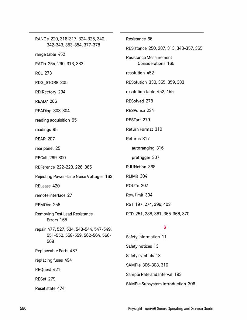
RANGe 220, 316-317, 324-325, 340,342-343, 353-354, 377-378
range table 452
RATio 254, 290, 313, 383
RCL 273
RDG_STORE 305
RDIRectory 294
READ? 206
READing 303-304
reading acquisition 95
readings 95
REAR 207
rear panel 25
RECall 299-300
REFerence 222-223, 226, 365
Rejecting Power–Line Noise Voltages 163
RELease 420
remote interface 27
REMOve 258
Removing Test Lead ResistanceErrors 165
repair 477, 527, 534, 543-544, 547-549,551-552, 558-559, 562-564, 566-568
Replaceable Parts 487
replacing fuses 494
REQuest 421
RESet 279
Reset state 474
Resistance 66
RESistance 250, 287, 313, 348-357, 365
Resistance MeasurementConsiderations 165
resolution 452
RESolution 330, 355, 359, 383
resolution table 452, 455
RESolved 278
RESPonse 234
RESTart 279
Return Format 310
Returns 317
autoranging 316
pretrigger 307
RJUNction 368
RLIMit 304
ROUTe 207
Row limit 304
RST 197, 274, 396, 403
RTD 251, 288, 361, 365-366, 370
S
Safety information 11
Safety notices 13
Safety symbols 13
SAMPle 306-308, 310
Sample Rate and Interval 193
SAMPle Subsystem Introduction 306
580 Keysight Truevolt Series Operating and Service Guide
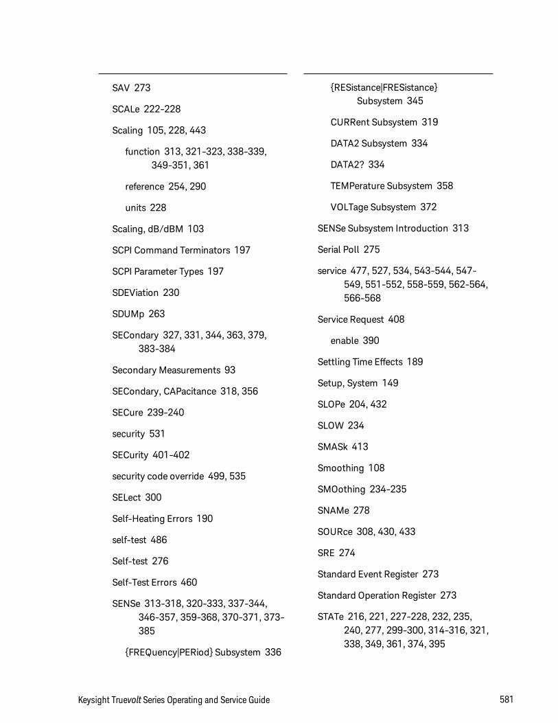
SAV 273
SCALe 222-228
Scaling 105, 228, 443
function 313, 321-323, 338-339,349-351, 361
reference 254, 290
units 228
Scaling, dB/dBM 103
SCPI Command Terminators 197
SCPI Parameter Types 197
SDEViation 230
SDUMp 263
SECondary 327, 331, 344, 363, 379,383-384
Secondary Measurements 93
SECondary, CAPacitance 318, 356
SECure 239-240
security 531
SECurity 401-402
security code override 499, 535
SELect 300
Self-Heating Errors 190
self-test 486
Self-test 276
Self-Test Errors 460
SENSe 313-318, 320-333, 337-344,346-357, 359-368, 370-371, 373-385
FREQuency|PERiod Subsystem 336
RESistance|FRESistanceSubsystem 345
CURRent Subsystem 319
DATA2 Subsystem 334
DATA2? 334
TEMPerature Subsystem 358
VOLTage Subsystem 372
SENSe Subsystem Introduction 313
Serial Poll 275
service 477, 527, 534, 543-544, 547-549, 551-552, 558-559, 562-564,566-568
Service Request 408
enable 390
Settling Time Effects 189
Setup, System 149
SLOPe 204, 432
SLOW 234
SMASk 413
Smoothing 108
SMOothing 234-235
SNAMe 278
SOURce 308, 430, 433
SRE 274
Standard Event Register 273
Standard Operation Register 273
STATe 216, 221, 227-228, 232, 235,240, 277, 299-300, 314-316, 321,338, 349, 361, 374, 395
Keysight Truevolt Series Operating and Service Guide 581
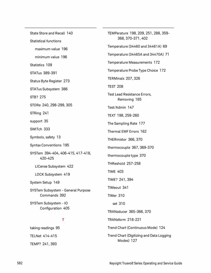
State Store and Recall 140
Statistical functions
maximum value 196
minimum value 196
Statistics 109
STATus 389-391
Status Byte Register 273
STATus Subsystem 386
STB? 275
STORe 240, 298-299, 305
STRing 241
support 35
SWITch 333
Symbols, safety 13
Syntax Conventions 195
SYSTem 394-404, 406-415, 417-418,420-425
LICense Subsystem 422
LOCK Subsystem 419
System Setup 149
SYSTem Subsystem - General PurposeCommands 392
SYSTem Subsystem - IOConfiguration 405
T
taking readings 95
TELNet 414-415
TEMP? 241, 393
TEMPerature 198, 209, 251, 288, 359-368, 370-371, 402
Temperature (34460 and 34461A) 69
Temperature (34465A and 34470A) 71
Temperature Measurements 172
Temperature Probe Type Choice 172
TERMinals 207, 326
TEST 208
Test Lead Resistance Errors,Removing 165
Test/Admin 147
TEXT 198, 259-260
The Sampling Rate 177
Thermal EMF Errors 162
THERmistor 366, 370
thermocouple 367, 369-370
thermocouple type 370
THReshold 257-258
TIME 403
TIME? 241, 394
TIMeout 341
TIMer 310
set 310
TRANsducer 365-366, 370
TRANsform 218-221
Trend Chart (Continuous Mode) 124
Trend Chart (Digitizing and Data LoggingModes) 127
582 Keysight Truevolt Series Operating and Service Guide
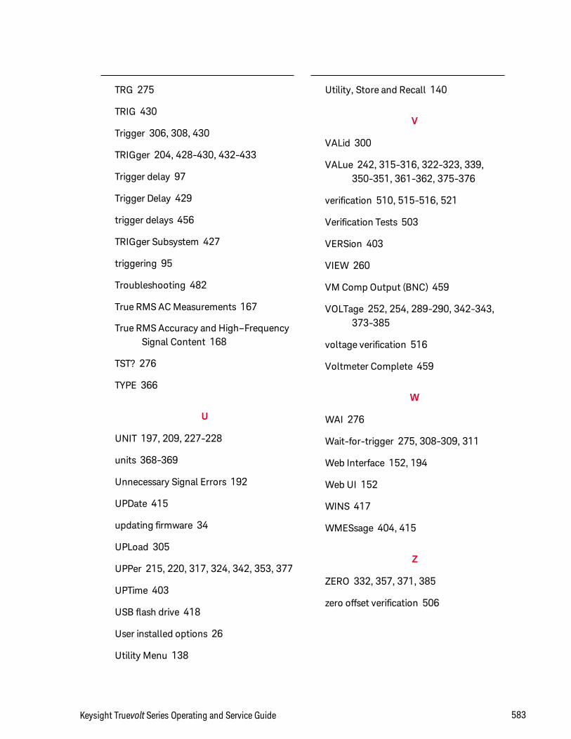
TRG 275
TRIG 430
Trigger 306, 308, 430
TRIGger 204, 428-430, 432-433
Trigger delay 97
Trigger Delay 429
trigger delays 456
TRIGger Subsystem 427
triggering 95
Troubleshooting 482
True RMS AC Measurements 167
True RMS Accuracy and High–FrequencySignal Content 168
TST? 276
TYPE 366
U
UNIT 197, 209, 227-228
units 368-369
Unnecessary Signal Errors 192
UPDate 415
updating firmware 34
UPLoad 305
UPPer 215, 220, 317, 324, 342, 353, 377
UPTime 403
USB flash drive 418
User installed options 26
Utility Menu 138
Utility, Store and Recall 140
V
VALid 300
VALue 242, 315-316, 322-323, 339,350-351, 361-362, 375-376
verification 510, 515-516, 521
Verification Tests 503
VERSion 403
VIEW 260
VM Comp Output (BNC) 459
VOLTage 252, 254, 289-290, 342-343,373-385
voltage verification 516
Voltmeter Complete 459
W
WAI 276
Wait-for-trigger 275, 308-309, 311
Web Interface 152, 194
Web UI 152
WINS 417
WMESsage 404, 415
Z
ZERO 332, 357, 371, 385
zero offset verification 506
Keysight Truevolt Series Operating and Service Guide 583

© Keysight Technologies, Inc. 2013 - 2018All rights reserved.
Part Number: 34460-90901
Printed in Malaysia: 27 November 2018 Edition 6