Embed Size (px)
Citation preview
User’s Guide
Keysight E4980A/AL Precision LCR Meter

Notices
© Keysight Technologies 2006-2019
No part of this manual may be reproduced in any form or by any means (including electronic storage and retrieval or translation into a foreign language) without prior agreement and written consent from Keysight Technologies, Inc. as governed by United States and international copyright laws.
Trademark Acknowledgments
Manual Part Number
E4980-90230
Edition
Edition 16, October 2019
Printed in Malaysia
Published by:
Keysight Technologies International Japan G.K,1-3-3 Higashikawasaki-choChuo-ku Kobe-shi, Hyogo, Japan
Warranty
THE MATERIAL CONTAINED IN THIS DOCUMENT IS PROVIDED “AS IS,” AND IS SUBJECT TO BEING CHANGED, WITHOUT NOTICE, IN FUTURE EDITIONS. FURTHER, TO THE MAXIMUM EXTENT PERMITTED BY APPLICABLE LAW, KEYSIGHT DISCLAIMS ALL WARRANTIES, EITHER EXPRESS OR IMPLIED WITH REGARD TO THIS MANUAL AND ANY INFORMATION CONTAINED HEREIN, INCLUDING BUT NOT LIMITED TO THE IMPLIED WARRANTIES OF MERCHANTABILITY AND FITNESS FOR A PARTICULAR PURPOSE. KEYSIGHT SHALL NOT BE LIABLE FOR ERRORS OR FOR INCIDENTAL OR CONSEQUENTIAL DAMAGES IN CONNECTION WITH THE FURNISHING, USE, OR PERFORMANCE OF THIS DOCUMENT OR ANY INFORMATION CONTAINED HEREIN. SHOULD KEYSIGHT AND THE USER HAVE A SEPARATE WRITTEN AGREEMENT WITH WARRANTY TERMS
COVERING THE MATERIAL IN THIS DOCUMENT THAT CONFLICT WITH THESE TERMS, THE WARRANTY TERMS IN THE SEPARATE AGREEMENT WILL CONTROL.
Technology Licenses
The hardware and/or software described in this document are furnished under a license and may be used or copied only in accordance with the terms of such license.
Declaration of Conformity
Declarations of Conformity for this product and for other Keysight products may be downloaded from the Web. Go to http://www.keysight.com/go/conformity. You can then search by product number to find the latest Declaration of Conformity.
U.S. Government Rights
The Software is “commercial computer software,” as defined by Federal Acquisition Regulation (“FAR”) 2.101. Pursuant to FAR 12.212 and 27.405-3 and Department of Defense FAR Supplement (“DFARS”) 227.7202, the U.S. government acquires commercial computer software under the same terms by which the software is customarily provided to the public. Accordingly, Keysight provides the Software to U.S. government customers under its standard commercial license, which is embodied in its End User License Agreement (EULA), a copy of which can be found at http://www.keysight.com/find/sweula. The license set forth in the EULA represents the exclusive authority by which the U.S. government may use, modify, distribute, or disclose the Software. The EULA and the license set forth therein, does not require or permit, among other things, that Keysight: (1) Furnish technical information related to commercial computer software or commercial computer software documentation that is not customarily provided to the public; or (2) Relinquish to, or otherwise provide, the government rights in excess of these rights customarily provided to the public to use, modify, reproduce, release,
perform, display, or disclose commercial computer software or commercial computer software documentation. No additional government requirements beyond those set forth in the EULA shall apply, except to the extent that those terms, rights, or licenses are explicitly required from all providers of commercial computer software pursuant to the FAR and the DFARS and are set forth specifically in writing elsewhere in the EULA. Keysight shall be under no obligation to update, revise or otherwise modify the Software. With respect to any technical data as defined by FAR 2.101, pursuant to FAR 12.211 and 27.404.2 and DFARS 227.7102, the U.S. government acquires no greater than Limited Rights as defined in FAR 27.401 or DFAR 227.7103-5 (c), as applicable in any technical data.
Safety Notices
A CAUTION notice denotes a hazard. It calls attention to an operating procedure, practice, or the like that, if not correctly performed or adhered to, could result in damage to the product or loss of important data. Do not proceed beyond a CAUTION notice until the indicated conditions are fully understood and met.
A WARNING notice denotes a hazard. It calls attention to an operating procedure, practice, or the like that, if not correctly performed or adhered to, could result in personal injury or death. Do not proceed beyond a WARNING notice until the indicated conditions are fully understood and met.
Contents
Keysight E4980A/AL User’s Guide 3
Table of Contents
1. Unpacking and Preparation
Contents of this Chapter . . . . . . . . . . . . . . . . . . . . . . . . . . . . . . . . . . . . . . . . . . . . . . . . . . . . . 17
Checking the Shipment . . . . . . . . . . . . . . . . . . . . . . . . . . . . . . . . . . . . . . . . . . . . . . . . . . . . . . 18
Preparations before Use . . . . . . . . . . . . . . . . . . . . . . . . . . . . . . . . . . . . . . . . . . . . . . . . . . . . . . 20Verifying the Power Supply . . . . . . . . . . . . . . . . . . . . . . . . . . . . . . . . . . . . . . . . . . . . . . . . 20Setting up the Fuse . . . . . . . . . . . . . . . . . . . . . . . . . . . . . . . . . . . . . . . . . . . . . . . . . . . . . . 20Verifying and Connecting the Power Cable . . . . . . . . . . . . . . . . . . . . . . . . . . . . . . . . . . . . 21
How to Remove the Handle . . . . . . . . . . . . . . . . . . . . . . . . . . . . . . . . . . . . . . . . . . . . . . . . . . . 23
Caution when Using the Handle . . . . . . . . . . . . . . . . . . . . . . . . . . . . . . . . . . . . . . . . . . . . . . . 24
Environmental Requirements . . . . . . . . . . . . . . . . . . . . . . . . . . . . . . . . . . . . . . . . . . . . . . . . . . 25Operating Environments. . . . . . . . . . . . . . . . . . . . . . . . . . . . . . . . . . . . . . . . . . . . . . . . . . . 25Ventilation Requirements . . . . . . . . . . . . . . . . . . . . . . . . . . . . . . . . . . . . . . . . . . . . . . . . . . 26Protection Against Electrostatic Discharge (ESD) . . . . . . . . . . . . . . . . . . . . . . . . . . . . . . . 27Ensuring Adequate Free Space around the LCR meter for Immediate Disconnection of the Power Cable in Case of Emergency . . . . . . . . . . . . . . . . . . . . . . . . . . . . . . . . . . . . . . . . . . 27
Starting the E4980A/AL . . . . . . . . . . . . . . . . . . . . . . . . . . . . . . . . . . . . . . . . . . . . . . . . . . . . . . 28Turning the Power ON and OFF . . . . . . . . . . . . . . . . . . . . . . . . . . . . . . . . . . . . . . . . . . . . . 28Disconnecting from the Supply Source . . . . . . . . . . . . . . . . . . . . . . . . . . . . . . . . . . . . . . . 29
2. Overview
Product Introduction. . . . . . . . . . . . . . . . . . . . . . . . . . . . . . . . . . . . . . . . . . . . . . . . . . . . . . . . . 31
Front Panel: Names and Functions of Parts . . . . . . . . . . . . . . . . . . . . . . . . . . . . . . . . . . . . . . 321. Power switch . . . . . . . . . . . . . . . . . . . . . . . . . . . . . . . . . . . . . . . . . . . . . . . . . . . . . . . . . 332. LCD . . . . . . . . . . . . . . . . . . . . . . . . . . . . . . . . . . . . . . . . . . . . . . . . . . . . . . . . . . . . . . . . 333. Softkeys . . . . . . . . . . . . . . . . . . . . . . . . . . . . . . . . . . . . . . . . . . . . . . . . . . . . . . . . . . . . . 334. Menu keys. . . . . . . . . . . . . . . . . . . . . . . . . . . . . . . . . . . . . . . . . . . . . . . . . . . . . . . . . . . . 335. Cursor keys . . . . . . . . . . . . . . . . . . . . . . . . . . . . . . . . . . . . . . . . . . . . . . . . . . . . . . . . . . . 336. Entry keys . . . . . . . . . . . . . . . . . . . . . . . . . . . . . . . . . . . . . . . . . . . . . . . . . . . . . . . . . . . . 347. LED indicator . . . . . . . . . . . . . . . . . . . . . . . . . . . . . . . . . . . . . . . . . . . . . . . . . . . . . . . . . 348. Preset key . . . . . . . . . . . . . . . . . . . . . . . . . . . . . . . . . . . . . . . . . . . . . . . . . . . . . . . . . . . . 349. Trigger key . . . . . . . . . . . . . . . . . . . . . . . . . . . . . . . . . . . . . . . . . . . . . . . . . . . . . . . . . . . 3410. DC Bias key. . . . . . . . . . . . . . . . . . . . . . . . . . . . . . . . . . . . . . . . . . . . . . . . . . . . . . . . . . 3411. DC Source key . . . . . . . . . . . . . . . . . . . . . . . . . . . . . . . . . . . . . . . . . . . . . . . . . . . . . . . 3412. UNKNOWN terminals . . . . . . . . . . . . . . . . . . . . . . . . . . . . . . . . . . . . . . . . . . . . . . . . . 3513. Front USB port . . . . . . . . . . . . . . . . . . . . . . . . . . . . . . . . . . . . . . . . . . . . . . . . . . . . . . . 3514. Ground terminal . . . . . . . . . . . . . . . . . . . . . . . . . . . . . . . . . . . . . . . . . . . . . . . . . . . . . . 3615. DC Source terminal . . . . . . . . . . . . . . . . . . . . . . . . . . . . . . . . . . . . . . . . . . . . . . . . . . . 36
Rear Panel: Names and Functions of Parts . . . . . . . . . . . . . . . . . . . . . . . . . . . . . . . . . . . . . . . 371. GPIB Interface Connector . . . . . . . . . . . . . . . . . . . . . . . . . . . . . . . . . . . . . . . . . . . . . . . 37
4 Keysight E4980A/AL User’s Guide
Contents
2. Interface Connector. . . . . . . . . . . . . . . . . . . . . . . . . . . . . . . . . . . . . . . . . . . . . . . . . . . . .373. USB (USBTMC) Interface Port. . . . . . . . . . . . . . . . . . . . . . . . . . . . . . . . . . . . . . . . . . . . .384. LAN Port . . . . . . . . . . . . . . . . . . . . . . . . . . . . . . . . . . . . . . . . . . . . . . . . . . . . . . . . . . . . .385. External Trigger Input Connector . . . . . . . . . . . . . . . . . . . . . . . . . . . . . . . . . . . . . . . . . .386. Serial Number Plate . . . . . . . . . . . . . . . . . . . . . . . . . . . . . . . . . . . . . . . . . . . . . . . . . . . .387. Power Cable Receptacle (to LINE) . . . . . . . . . . . . . . . . . . . . . . . . . . . . . . . . . . . . . . . . .398. Fan . . . . . . . . . . . . . . . . . . . . . . . . . . . . . . . . . . . . . . . . . . . . . . . . . . . . . . . . . . . . . . . . . .39
Screen Area: Names and Functions of Parts. . . . . . . . . . . . . . . . . . . . . . . . . . . . . . . . . . . . . . .401. Display Page Area . . . . . . . . . . . . . . . . . . . . . . . . . . . . . . . . . . . . . . . . . . . . . . . . . . . . . .402. Comment Line Area. . . . . . . . . . . . . . . . . . . . . . . . . . . . . . . . . . . . . . . . . . . . . . . . . . . . .403. Softkey Area. . . . . . . . . . . . . . . . . . . . . . . . . . . . . . . . . . . . . . . . . . . . . . . . . . . . . . . . . . .414. Measurement Data/Conditions Area. . . . . . . . . . . . . . . . . . . . . . . . . . . . . . . . . . . . . . . .415. Input Line Area . . . . . . . . . . . . . . . . . . . . . . . . . . . . . . . . . . . . . . . . . . . . . . . . . . . . . . . .426. System Message Area . . . . . . . . . . . . . . . . . . . . . . . . . . . . . . . . . . . . . . . . . . . . . . . . . . .427. Status Display Area . . . . . . . . . . . . . . . . . . . . . . . . . . . . . . . . . . . . . . . . . . . . . . . . . . . . .42
Basic Operation . . . . . . . . . . . . . . . . . . . . . . . . . . . . . . . . . . . . . . . . . . . . . . . . . . . . . . . . . . . . .43How to Use Cursor Keys . . . . . . . . . . . . . . . . . . . . . . . . . . . . . . . . . . . . . . . . . . . . . . . . . . .43How to Use Skip Keys . . . . . . . . . . . . . . . . . . . . . . . . . . . . . . . . . . . . . . . . . . . . . . . . . . . . .44
3. Display Format
MEAS DISPLAY Page . . . . . . . . . . . . . . . . . . . . . . . . . . . . . . . . . . . . . . . . . . . . . . . . . . . . . . . . .45Measurement Function . . . . . . . . . . . . . . . . . . . . . . . . . . . . . . . . . . . . . . . . . . . . . . . . . . . .47Impedance range. . . . . . . . . . . . . . . . . . . . . . . . . . . . . . . . . . . . . . . . . . . . . . . . . . . . . . . . .51Test Frequency. . . . . . . . . . . . . . . . . . . . . . . . . . . . . . . . . . . . . . . . . . . . . . . . . . . . . . . . . . .58Test Signal Level . . . . . . . . . . . . . . . . . . . . . . . . . . . . . . . . . . . . . . . . . . . . . . . . . . . . . . . . .61DC Bias . . . . . . . . . . . . . . . . . . . . . . . . . . . . . . . . . . . . . . . . . . . . . . . . . . . . . . . . . . . . . . . .64Measurement Time Mode . . . . . . . . . . . . . . . . . . . . . . . . . . . . . . . . . . . . . . . . . . . . . . . . . .68Display Setting for Measurement Results. . . . . . . . . . . . . . . . . . . . . . . . . . . . . . . . . . . . . .69Displaying Errors instead of Measurement Results . . . . . . . . . . . . . . . . . . . . . . . . . . . . . .71Monitor Information. . . . . . . . . . . . . . . . . . . . . . . . . . . . . . . . . . . . . . . . . . . . . . . . . . . . . . .75
BIN NO. DISPLAY Page . . . . . . . . . . . . . . . . . . . . . . . . . . . . . . . . . . . . . . . . . . . . . . . . . . . . . . .76Comparator Function ON/OFF . . . . . . . . . . . . . . . . . . . . . . . . . . . . . . . . . . . . . . . . . . . . . .77
BIN COUNT DISPLAY Page . . . . . . . . . . . . . . . . . . . . . . . . . . . . . . . . . . . . . . . . . . . . . . . . . . . .79Counter Function. . . . . . . . . . . . . . . . . . . . . . . . . . . . . . . . . . . . . . . . . . . . . . . . . . . . . . . . .81
LIST SWEEP DISPLAY Page. . . . . . . . . . . . . . . . . . . . . . . . . . . . . . . . . . . . . . . . . . . . . . . . . . . .82Sweep Mode . . . . . . . . . . . . . . . . . . . . . . . . . . . . . . . . . . . . . . . . . . . . . . . . . . . . . . . . . . . .84
DISPLAY BLANK Page . . . . . . . . . . . . . . . . . . . . . . . . . . . . . . . . . . . . . . . . . . . . . . . . . . . . . . . .86
4. Configuring Measurement Conditions (Display and Function Related Settings)
Initializing the Instrument . . . . . . . . . . . . . . . . . . . . . . . . . . . . . . . . . . . . . . . . . . . . . . . . . . . . .87
MEAS SETUP page . . . . . . . . . . . . . . . . . . . . . . . . . . . . . . . . . . . . . . . . . . . . . . . . . . . . . . . . . .88
Contents
Keysight E4980A/AL User’s Guide 5
Comment line . . . . . . . . . . . . . . . . . . . . . . . . . . . . . . . . . . . . . . . . . . . . . . . . . . . . . . . . . . . 90Trigger mode . . . . . . . . . . . . . . . . . . . . . . . . . . . . . . . . . . . . . . . . . . . . . . . . . . . . . . . . . . . 91Automatic level control . . . . . . . . . . . . . . . . . . . . . . . . . . . . . . . . . . . . . . . . . . . . . . . . . . . 93DC Bias Current Isolation . . . . . . . . . . . . . . . . . . . . . . . . . . . . . . . . . . . . . . . . . . . . . . . . . . 97Averaging Factor . . . . . . . . . . . . . . . . . . . . . . . . . . . . . . . . . . . . . . . . . . . . . . . . . . . . . . . . 98Trigger Delay Time . . . . . . . . . . . . . . . . . . . . . . . . . . . . . . . . . . . . . . . . . . . . . . . . . . . . . . . 99Step Delay Time . . . . . . . . . . . . . . . . . . . . . . . . . . . . . . . . . . . . . . . . . . . . . . . . . . . . . . . . 101DC Bias Voltage Monitor . . . . . . . . . . . . . . . . . . . . . . . . . . . . . . . . . . . . . . . . . . . . . . . . . 103DC Bias Current Monitor . . . . . . . . . . . . . . . . . . . . . . . . . . . . . . . . . . . . . . . . . . . . . . . . . 104DCR Range . . . . . . . . . . . . . . . . . . . . . . . . . . . . . . . . . . . . . . . . . . . . . . . . . . . . . . . . . . . . 105DCI Range. . . . . . . . . . . . . . . . . . . . . . . . . . . . . . . . . . . . . . . . . . . . . . . . . . . . . . . . . . . . . 106DC Source. . . . . . . . . . . . . . . . . . . . . . . . . . . . . . . . . . . . . . . . . . . . . . . . . . . . . . . . . . . . . 107Automatic Bias Polarity Control . . . . . . . . . . . . . . . . . . . . . . . . . . . . . . . . . . . . . . . . . . . 108Deviation Measurement . . . . . . . . . . . . . . . . . . . . . . . . . . . . . . . . . . . . . . . . . . . . . . . . . . 110
CORRECTION page . . . . . . . . . . . . . . . . . . . . . . . . . . . . . . . . . . . . . . . . . . . . . . . . . . . . . . . . 112To set the correction function to on or off . . . . . . . . . . . . . . . . . . . . . . . . . . . . . . . . . . . . 113The correction functions of the E4980A/AL are operated as follows:. . . . . . . . . . . . . . . 114Open Correction . . . . . . . . . . . . . . . . . . . . . . . . . . . . . . . . . . . . . . . . . . . . . . . . . . . . . . . . 115Short Correction . . . . . . . . . . . . . . . . . . . . . . . . . . . . . . . . . . . . . . . . . . . . . . . . . . . . . . . . 119Correction Based on User-Specified Frequency Points. . . . . . . . . . . . . . . . . . . . . . . . . . 121Relationships between Correction Based on All Frequency Points and Correction Based on Specified Frequency Points . . . . . . . . . . . . . . . . . . . . . . . . . . . . . . . . . . . . . . . . . . . . . . . 128Reading/Writing Correction Data . . . . . . . . . . . . . . . . . . . . . . . . . . . . . . . . . . . . . . . . . . 130Measurement Functions for the Standard . . . . . . . . . . . . . . . . . . . . . . . . . . . . . . . . . . . . 131Selecting Single/Multiple Correction Mode . . . . . . . . . . . . . . . . . . . . . . . . . . . . . . . . . . 132Selecting the Cable Length . . . . . . . . . . . . . . . . . . . . . . . . . . . . . . . . . . . . . . . . . . . . . . . 133
LIMIT TABLE SETUP Page . . . . . . . . . . . . . . . . . . . . . . . . . . . . . . . . . . . . . . . . . . . . . . . . . . . 134Parameter Swap Feature . . . . . . . . . . . . . . . . . . . . . . . . . . . . . . . . . . . . . . . . . . . . . . . . . 135Comparator Limit Mode . . . . . . . . . . . . . . . . . . . . . . . . . . . . . . . . . . . . . . . . . . . . . . . . . . 137Tolerance Mode Nominal Value . . . . . . . . . . . . . . . . . . . . . . . . . . . . . . . . . . . . . . . . . . . . 139Turning On/Off the Comparator . . . . . . . . . . . . . . . . . . . . . . . . . . . . . . . . . . . . . . . . . . . . 140Turning On/Off the Auxiliary Bin . . . . . . . . . . . . . . . . . . . . . . . . . . . . . . . . . . . . . . . . . . . 141Beep Feature . . . . . . . . . . . . . . . . . . . . . . . . . . . . . . . . . . . . . . . . . . . . . . . . . . . . . . . . . . 143Lower and Upper Limits . . . . . . . . . . . . . . . . . . . . . . . . . . . . . . . . . . . . . . . . . . . . . . . . . 144
LIST SWEEP SETUP Page . . . . . . . . . . . . . . . . . . . . . . . . . . . . . . . . . . . . . . . . . . . . . . . . . . . 147Sweep Mode. . . . . . . . . . . . . . . . . . . . . . . . . . . . . . . . . . . . . . . . . . . . . . . . . . . . . . . . . . . 148List Sweep Parameters. . . . . . . . . . . . . . . . . . . . . . . . . . . . . . . . . . . . . . . . . . . . . . . . . . . 149Sweep Points and Limit Modes . . . . . . . . . . . . . . . . . . . . . . . . . . . . . . . . . . . . . . . . . . . . 150Sweep Parameter Auto-completion . . . . . . . . . . . . . . . . . . . . . . . . . . . . . . . . . . . . . . . . 153
5. System Configurations
SYSTEM INFO Page . . . . . . . . . . . . . . . . . . . . . . . . . . . . . . . . . . . . . . . . . . . . . . . . . . . . . . . . 155
6 Keysight E4980A/AL User’s Guide
Contents
Handler Interface. . . . . . . . . . . . . . . . . . . . . . . . . . . . . . . . . . . . . . . . . . . . . . . . . . . . . . . .156Scanner Interface . . . . . . . . . . . . . . . . . . . . . . . . . . . . . . . . . . . . . . . . . . . . . . . . . . . . . . .157Monitor Information. . . . . . . . . . . . . . . . . . . . . . . . . . . . . . . . . . . . . . . . . . . . . . . . . . . . . .157
SYSTEM CONFIG Page . . . . . . . . . . . . . . . . . . . . . . . . . . . . . . . . . . . . . . . . . . . . . . . . . . . . . .158Turning On/Off the Beep Feature . . . . . . . . . . . . . . . . . . . . . . . . . . . . . . . . . . . . . . . . . . .159Changing the Beep Tone . . . . . . . . . . . . . . . . . . . . . . . . . . . . . . . . . . . . . . . . . . . . . . . . .160Changing the Beep Tone . . . . . . . . . . . . . . . . . . . . . . . . . . . . . . . . . . . . . . . . . . . . . . . . .161Configuring the System Date . . . . . . . . . . . . . . . . . . . . . . . . . . . . . . . . . . . . . . . . . . . . . .161Configuring the GPIB Address. . . . . . . . . . . . . . . . . . . . . . . . . . . . . . . . . . . . . . . . . . . . . .163Configuring the LAN IP address . . . . . . . . . . . . . . . . . . . . . . . . . . . . . . . . . . . . . . . . . . . .164
SELF TEST Page . . . . . . . . . . . . . . . . . . . . . . . . . . . . . . . . . . . . . . . . . . . . . . . . . . . . . . . . . . .166Choosing a Test Item. . . . . . . . . . . . . . . . . . . . . . . . . . . . . . . . . . . . . . . . . . . . . . . . . . . . .167
SERVICE Page . . . . . . . . . . . . . . . . . . . . . . . . . . . . . . . . . . . . . . . . . . . . . . . . . . . . . . . . . . . . .168Monitor Information. . . . . . . . . . . . . . . . . . . . . . . . . . . . . . . . . . . . . . . . . . . . . . . . . . . . . .169Saving the System Information into External Memory . . . . . . . . . . . . . . . . . . . . . . . . . . .169
6. Save/Recall
Overview of Save/Recall Functionality . . . . . . . . . . . . . . . . . . . . . . . . . . . . . . . . . . . . . . . . . .171Save Methods and Their Uses. . . . . . . . . . . . . . . . . . . . . . . . . . . . . . . . . . . . . . . . . . . . . .171Folder/File Structure on USB Memory . . . . . . . . . . . . . . . . . . . . . . . . . . . . . . . . . . . . . . .172USB Memory Notes . . . . . . . . . . . . . . . . . . . . . . . . . . . . . . . . . . . . . . . . . . . . . . . . . . . . . .173
Saving/Recalling Instrument Configuration States . . . . . . . . . . . . . . . . . . . . . . . . . . . . . . . .174Overview of Instrument Configurations . . . . . . . . . . . . . . . . . . . . . . . . . . . . . . . . . . . . . .174Medium Mode . . . . . . . . . . . . . . . . . . . . . . . . . . . . . . . . . . . . . . . . . . . . . . . . . . . . . . . . . .175Choosing a Register Number . . . . . . . . . . . . . . . . . . . . . . . . . . . . . . . . . . . . . . . . . . . . . .176Memory Status Information . . . . . . . . . . . . . . . . . . . . . . . . . . . . . . . . . . . . . . . . . . . . . . .176Comment Information . . . . . . . . . . . . . . . . . . . . . . . . . . . . . . . . . . . . . . . . . . . . . . . . . . . .177Saving/Recalling Instrument Configuration States into/from the Internal Memory . . . .177Saving/Recalling Instrument Configuration States into/from USB Memory . . . . . . . . . .179Using the Auto Recall Feature. . . . . . . . . . . . . . . . . . . . . . . . . . . . . . . . . . . . . . . . . . . . . .181
Saving Measurement Results into USB Memory . . . . . . . . . . . . . . . . . . . . . . . . . . . . . . . . . .182Measurement Result Format. . . . . . . . . . . . . . . . . . . . . . . . . . . . . . . . . . . . . . . . . . . . . . .182To save measurement results into USB memory: . . . . . . . . . . . . . . . . . . . . . . . . . . . . . .185How to save the measurement result of List Sweep Measurement to USB memory. . . .186
Saving a Screenshot into USB Memory . . . . . . . . . . . . . . . . . . . . . . . . . . . . . . . . . . . . . . . . .188To save a screenshot into USB memory . . . . . . . . . . . . . . . . . . . . . . . . . . . . . . . . . . . . . .188
7. Measurement Procedure and Examples
Basic Measurement Procedure . . . . . . . . . . . . . . . . . . . . . . . . . . . . . . . . . . . . . . . . . . . . . . . .189
Impedance Parameters . . . . . . . . . . . . . . . . . . . . . . . . . . . . . . . . . . . . . . . . . . . . . . . . . . . . . .191
Parallel/Series Circuit Mode . . . . . . . . . . . . . . . . . . . . . . . . . . . . . . . . . . . . . . . . . . . . . . . . . .194
Contents
Keysight E4980A/AL User’s Guide 7
Selecting Circuit Mode of Capacitance . . . . . . . . . . . . . . . . . . . . . . . . . . . . . . . . . . . . . . 195Selecting Circuit Mode of Inductance . . . . . . . . . . . . . . . . . . . . . . . . . . . . . . . . . . . . . . . 196
Test Signal Level . . . . . . . . . . . . . . . . . . . . . . . . . . . . . . . . . . . . . . . . . . . . . . . . . . . . . . . . . . . 197Test Signal Level Across the DUT. . . . . . . . . . . . . . . . . . . . . . . . . . . . . . . . . . . . . . . . . . . 197Test Signal Level Setting . . . . . . . . . . . . . . . . . . . . . . . . . . . . . . . . . . . . . . . . . . . . . . . . . 198
Four-Terminal Pair Configuration . . . . . . . . . . . . . . . . . . . . . . . . . . . . . . . . . . . . . . . . . . . . . . 199
Measurement Contacts . . . . . . . . . . . . . . . . . . . . . . . . . . . . . . . . . . . . . . . . . . . . . . . . . . . . . 201Capacitance to Ground . . . . . . . . . . . . . . . . . . . . . . . . . . . . . . . . . . . . . . . . . . . . . . . . . . 201Contact Resistance . . . . . . . . . . . . . . . . . . . . . . . . . . . . . . . . . . . . . . . . . . . . . . . . . . . . . 203Extending Test Leads . . . . . . . . . . . . . . . . . . . . . . . . . . . . . . . . . . . . . . . . . . . . . . . . . . . . 204Guarding for Measurement of Low Capacitance Values . . . . . . . . . . . . . . . . . . . . . . . . . 206Shielding. . . . . . . . . . . . . . . . . . . . . . . . . . . . . . . . . . . . . . . . . . . . . . . . . . . . . . . . . . . . . . 207
Correction Functions . . . . . . . . . . . . . . . . . . . . . . . . . . . . . . . . . . . . . . . . . . . . . . . . . . . . . . . 208Performing OPEN Correction . . . . . . . . . . . . . . . . . . . . . . . . . . . . . . . . . . . . . . . . . . . . . . 210Performing SHORT Correction . . . . . . . . . . . . . . . . . . . . . . . . . . . . . . . . . . . . . . . . . . . . . 210Performing LOAD Correction . . . . . . . . . . . . . . . . . . . . . . . . . . . . . . . . . . . . . . . . . . . . . . 210
Parasitics Incident to DUT Connection . . . . . . . . . . . . . . . . . . . . . . . . . . . . . . . . . . . . . . . . . 212
Characteristics Example . . . . . . . . . . . . . . . . . . . . . . . . . . . . . . . . . . . . . . . . . . . . . . . . . . . . . 213
Capacitor Measurements . . . . . . . . . . . . . . . . . . . . . . . . . . . . . . . . . . . . . . . . . . . . . . . . . . . . 215
Inductance Measurements . . . . . . . . . . . . . . . . . . . . . . . . . . . . . . . . . . . . . . . . . . . . . . . . . . . 218
Measurements Using DC source . . . . . . . . . . . . . . . . . . . . . . . . . . . . . . . . . . . . . . . . . . . . . . 221
8. Overview of Remote Control
Types of remote control system . . . . . . . . . . . . . . . . . . . . . . . . . . . . . . . . . . . . . . . . . . . . . . . 225
GPIB remote control system. . . . . . . . . . . . . . . . . . . . . . . . . . . . . . . . . . . . . . . . . . . . . . . . . . 226What is GPIB?. . . . . . . . . . . . . . . . . . . . . . . . . . . . . . . . . . . . . . . . . . . . . . . . . . . . . . . . . . 226System configuration . . . . . . . . . . . . . . . . . . . . . . . . . . . . . . . . . . . . . . . . . . . . . . . . . . . . 226Device selector . . . . . . . . . . . . . . . . . . . . . . . . . . . . . . . . . . . . . . . . . . . . . . . . . . . . . . . . 227
LAN remote control system . . . . . . . . . . . . . . . . . . . . . . . . . . . . . . . . . . . . . . . . . . . . . . . . . . 228System configuration . . . . . . . . . . . . . . . . . . . . . . . . . . . . . . . . . . . . . . . . . . . . . . . . . . . . 228Control over SICL-LAN server . . . . . . . . . . . . . . . . . . . . . . . . . . . . . . . . . . . . . . . . . . . . . 230Control over telnet server. . . . . . . . . . . . . . . . . . . . . . . . . . . . . . . . . . . . . . . . . . . . . . . . . 234Control via Web server . . . . . . . . . . . . . . . . . . . . . . . . . . . . . . . . . . . . . . . . . . . . . . . . . . . 237
USB Remote Control System . . . . . . . . . . . . . . . . . . . . . . . . . . . . . . . . . . . . . . . . . . . . . . . . . 240System configuration . . . . . . . . . . . . . . . . . . . . . . . . . . . . . . . . . . . . . . . . . . . . . . . . . . . . 240
Sending SCPI command messages . . . . . . . . . . . . . . . . . . . . . . . . . . . . . . . . . . . . . . . . . . . . 246Types and structure of commands. . . . . . . . . . . . . . . . . . . . . . . . . . . . . . . . . . . . . . . . . . 246Grammar of messages . . . . . . . . . . . . . . . . . . . . . . . . . . . . . . . . . . . . . . . . . . . . . . . . . . 247Remote mode . . . . . . . . . . . . . . . . . . . . . . . . . . . . . . . . . . . . . . . . . . . . . . . . . . . . . . . . . . 248
Trigger System . . . . . . . . . . . . . . . . . . . . . . . . . . . . . . . . . . . . . . . . . . . . . . . . . . . . . . . . . . . . 249

8 Keysight E4980A/AL User’s Guide
Contents
System-wide states and transitions . . . . . . . . . . . . . . . . . . . . . . . . . . . . . . . . . . . . . . . . .249
Data Buffer Memory . . . . . . . . . . . . . . . . . . . . . . . . . . . . . . . . . . . . . . . . . . . . . . . . . . . . . . . .255Data Buffer Memory . . . . . . . . . . . . . . . . . . . . . . . . . . . . . . . . . . . . . . . . . . . . . . . . . . . . .255When Data Buffer Memory is Used. . . . . . . . . . . . . . . . . . . . . . . . . . . . . . . . . . . . . . . . . .256Output Format of Data Buffer Memory . . . . . . . . . . . . . . . . . . . . . . . . . . . . . . . . . . . . . . .258
Starting a Measurement Cycle (triggering the instrument) . . . . . . . . . . . . . . . . . . . . . . . . . .260Configuring the instrument to automatically perform continuous measurement . . . . . .260Starting Measurement on Demand. . . . . . . . . . . . . . . . . . . . . . . . . . . . . . . . . . . . . . . . . .260
Waiting for the End of Measurement . . . . . . . . . . . . . . . . . . . . . . . . . . . . . . . . . . . . . . . . . . .262Using the status register . . . . . . . . . . . . . . . . . . . . . . . . . . . . . . . . . . . . . . . . . . . . . . . . . .262
Data Transfer . . . . . . . . . . . . . . . . . . . . . . . . . . . . . . . . . . . . . . . . . . . . . . . . . . . . . . . . . . . . . .264Data Format. . . . . . . . . . . . . . . . . . . . . . . . . . . . . . . . . . . . . . . . . . . . . . . . . . . . . . . . . . . .264
Status Byte. . . . . . . . . . . . . . . . . . . . . . . . . . . . . . . . . . . . . . . . . . . . . . . . . . . . . . . . . . . . . . . .270Enabling the Status Byte. . . . . . . . . . . . . . . . . . . . . . . . . . . . . . . . . . . . . . . . . . . . . . . . . .272Operation Status Register Structure. . . . . . . . . . . . . . . . . . . . . . . . . . . . . . . . . . . . . . . . .273Standard Event Status Register . . . . . . . . . . . . . . . . . . . . . . . . . . . . . . . . . . . . . . . . . . . .276Enabling the Event Status Register . . . . . . . . . . . . . . . . . . . . . . . . . . . . . . . . . . . . . . . . .279
9. Sample Program
Set Up Measurement Conditions and LCD Display . . . . . . . . . . . . . . . . . . . . . . . . . . . . . . . .281
Detecting End of Measurement. . . . . . . . . . . . . . . . . . . . . . . . . . . . . . . . . . . . . . . . . . . . . . . .286
Read Measurement Results. . . . . . . . . . . . . . . . . . . . . . . . . . . . . . . . . . . . . . . . . . . . . . . . . . .290Read measurement data in ASCII format (Comparator). . . . . . . . . . . . . . . . . . . . . . . . . .290Read measurement data in ASCII format (Data buffer memory) . . . . . . . . . . . . . . . . . . .293Read measurement data in ASCII format (List sweep) . . . . . . . . . . . . . . . . . . . . . . . . . . .296Read measurement data in BINARY (comparator) . . . . . . . . . . . . . . . . . . . . . . . . . . . . . .299Read measurement data in BINARY format (Data buffer memory) . . . . . . . . . . . . . . . . .303Read measurement data in BINARY format (List sweep) . . . . . . . . . . . . . . . . . . . . . . . . .306
Save/Recall . . . . . . . . . . . . . . . . . . . . . . . . . . . . . . . . . . . . . . . . . . . . . . . . . . . . . . . . . . . . . . .309
Read/Write correction data at specified frequency points. . . . . . . . . . . . . . . . . . . . . . . . . . .312
10. SCPI Command Reference
Notational conventions in this command reference . . . . . . . . . . . . . . . . . . . . . . . . . . . . . . .320Syntax . . . . . . . . . . . . . . . . . . . . . . . . . . . . . . . . . . . . . . . . . . . . . . . . . . . . . . . . . . . . . . . .320Description. . . . . . . . . . . . . . . . . . . . . . . . . . . . . . . . . . . . . . . . . . . . . . . . . . . . . . . . . . . . .320Parameters . . . . . . . . . . . . . . . . . . . . . . . . . . . . . . . . . . . . . . . . . . . . . . . . . . . . . . . . . . . .320Equivalent key . . . . . . . . . . . . . . . . . . . . . . . . . . . . . . . . . . . . . . . . . . . . . . . . . . . . . . . . . .321
E4980A/AL commands . . . . . . . . . . . . . . . . . . . . . . . . . . . . . . . . . . . . . . . . . . . . . . . . . . . . . .322*CLS . . . . . . . . . . . . . . . . . . . . . . . . . . . . . . . . . . . . . . . . . . . . . . . . . . . . . . . . . . . . . . . . . .322*ESE . . . . . . . . . . . . . . . . . . . . . . . . . . . . . . . . . . . . . . . . . . . . . . . . . . . . . . . . . . . . . . . . . .322*ESR? . . . . . . . . . . . . . . . . . . . . . . . . . . . . . . . . . . . . . . . . . . . . . . . . . . . . . . . . . . . . . . . . .322
Contents
Keysight E4980A/AL User’s Guide 9
*IDN?. . . . . . . . . . . . . . . . . . . . . . . . . . . . . . . . . . . . . . . . . . . . . . . . . . . . . . . . . . . . . . . . . 323*LRN? . . . . . . . . . . . . . . . . . . . . . . . . . . . . . . . . . . . . . . . . . . . . . . . . . . . . . . . . . . . . . . . . 323*OPC . . . . . . . . . . . . . . . . . . . . . . . . . . . . . . . . . . . . . . . . . . . . . . . . . . . . . . . . . . . . . . . . . 323*OPC? . . . . . . . . . . . . . . . . . . . . . . . . . . . . . . . . . . . . . . . . . . . . . . . . . . . . . . . . . . . . . . . . 323*OPT? . . . . . . . . . . . . . . . . . . . . . . . . . . . . . . . . . . . . . . . . . . . . . . . . . . . . . . . . . . . . . . . . 323*RST . . . . . . . . . . . . . . . . . . . . . . . . . . . . . . . . . . . . . . . . . . . . . . . . . . . . . . . . . . . . . . . . . 323*SRE . . . . . . . . . . . . . . . . . . . . . . . . . . . . . . . . . . . . . . . . . . . . . . . . . . . . . . . . . . . . . . . . . 324*STB? . . . . . . . . . . . . . . . . . . . . . . . . . . . . . . . . . . . . . . . . . . . . . . . . . . . . . . . . . . . . . . . . 324*TRG . . . . . . . . . . . . . . . . . . . . . . . . . . . . . . . . . . . . . . . . . . . . . . . . . . . . . . . . . . . . . . . . . 324*TST?. . . . . . . . . . . . . . . . . . . . . . . . . . . . . . . . . . . . . . . . . . . . . . . . . . . . . . . . . . . . . . . . . 324*WAI . . . . . . . . . . . . . . . . . . . . . . . . . . . . . . . . . . . . . . . . . . . . . . . . . . . . . . . . . . . . . . . . . 325:ABORt . . . . . . . . . . . . . . . . . . . . . . . . . . . . . . . . . . . . . . . . . . . . . . . . . . . . . . . . . . . . . . . 325:AMPLitude:ALC . . . . . . . . . . . . . . . . . . . . . . . . . . . . . . . . . . . . . . . . . . . . . . . . . . . . . . . . 325:APERture . . . . . . . . . . . . . . . . . . . . . . . . . . . . . . . . . . . . . . . . . . . . . . . . . . . . . . . . . . . . . 325:BIAS:CURRent[:LEVel] . . . . . . . . . . . . . . . . . . . . . . . . . . . . . . . . . . . . . . . . . . . . . . . . . . . 326:BIAS:POLarity:AUTO . . . . . . . . . . . . . . . . . . . . . . . . . . . . . . . . . . . . . . . . . . . . . . . . . . . . 327:BIAS:POLarity:CURRent[:LEVel]? . . . . . . . . . . . . . . . . . . . . . . . . . . . . . . . . . . . . . . . . . . 327:BIAS:POLarity:VOLTage[:LEVel]? . . . . . . . . . . . . . . . . . . . . . . . . . . . . . . . . . . . . . . . . . . . 327:BIAS:RANGe:AUTO . . . . . . . . . . . . . . . . . . . . . . . . . . . . . . . . . . . . . . . . . . . . . . . . . . . . . 327:BIAS:STATe. . . . . . . . . . . . . . . . . . . . . . . . . . . . . . . . . . . . . . . . . . . . . . . . . . . . . . . . . . . . 328:BIAS:VOLTage[:LEVel] . . . . . . . . . . . . . . . . . . . . . . . . . . . . . . . . . . . . . . . . . . . . . . . . . . . 328:COMParator:ABIN . . . . . . . . . . . . . . . . . . . . . . . . . . . . . . . . . . . . . . . . . . . . . . . . . . . . . . 329:COMParator:BEEPer . . . . . . . . . . . . . . . . . . . . . . . . . . . . . . . . . . . . . . . . . . . . . . . . . . . . 329:COMParator:BIN:CLEar . . . . . . . . . . . . . . . . . . . . . . . . . . . . . . . . . . . . . . . . . . . . . . . . . . 330:COMParator:BIN:COUNt:CLEar . . . . . . . . . . . . . . . . . . . . . . . . . . . . . . . . . . . . . . . . . . . 330:COMParator:BIN:COUNt:DATA? . . . . . . . . . . . . . . . . . . . . . . . . . . . . . . . . . . . . . . . . . . . 330:COMParator:BIN:COUNt[:STATe] . . . . . . . . . . . . . . . . . . . . . . . . . . . . . . . . . . . . . . . . . . 330:COMParator:MODE . . . . . . . . . . . . . . . . . . . . . . . . . . . . . . . . . . . . . . . . . . . . . . . . . . . . . 331:COMParator:SEQuence:BIN . . . . . . . . . . . . . . . . . . . . . . . . . . . . . . . . . . . . . . . . . . . . . . 331:COMParator:SLIMit . . . . . . . . . . . . . . . . . . . . . . . . . . . . . . . . . . . . . . . . . . . . . . . . . . . . . 332:COMParator[:STATe] . . . . . . . . . . . . . . . . . . . . . . . . . . . . . . . . . . . . . . . . . . . . . . . . . . . . 332:COMParator:SWAP . . . . . . . . . . . . . . . . . . . . . . . . . . . . . . . . . . . . . . . . . . . . . . . . . . . . . 333:COMParator:TOLerance:BIN[1-9] . . . . . . . . . . . . . . . . . . . . . . . . . . . . . . . . . . . . . . . . . . 333:COMParator:TOLerance:NOMinal . . . . . . . . . . . . . . . . . . . . . . . . . . . . . . . . . . . . . . . . . . 334:CONTrol:CBIas:STATe . . . . . . . . . . . . . . . . . . . . . . . . . . . . . . . . . . . . . . . . . . . . . . . . . . . 334:CONTrol:HANDler:STATe . . . . . . . . . . . . . . . . . . . . . . . . . . . . . . . . . . . . . . . . . . . . . . . . . 334:CONTrol:SCANner:STATe. . . . . . . . . . . . . . . . . . . . . . . . . . . . . . . . . . . . . . . . . . . . . . . . . 335:CORRection:LENGth . . . . . . . . . . . . . . . . . . . . . . . . . . . . . . . . . . . . . . . . . . . . . . . . . . . . 335:CORRection:LOAD:STATe . . . . . . . . . . . . . . . . . . . . . . . . . . . . . . . . . . . . . . . . . . . . . . . . 336:CORRection:LOAD:TYPE . . . . . . . . . . . . . . . . . . . . . . . . . . . . . . . . . . . . . . . . . . . . . . . . . 336:CORRection:METHod . . . . . . . . . . . . . . . . . . . . . . . . . . . . . . . . . . . . . . . . . . . . . . . . . . . 337:CORRection:OPEN[:EXECute] . . . . . . . . . . . . . . . . . . . . . . . . . . . . . . . . . . . . . . . . . . . . . 338
10 Keysight E4980A/AL User’s Guide
Contents
:CORRection:OPEN:STATe . . . . . . . . . . . . . . . . . . . . . . . . . . . . . . . . . . . . . . . . . . . . . . . . .338:CORRection:SHORt[:EXECute]. . . . . . . . . . . . . . . . . . . . . . . . . . . . . . . . . . . . . . . . . . . . .338:CORRection:SHORt:STATe . . . . . . . . . . . . . . . . . . . . . . . . . . . . . . . . . . . . . . . . . . . . . . . .338:CORRection:SPOT[1-201]:FREQuency . . . . . . . . . . . . . . . . . . . . . . . . . . . . . . . . . . . . . .339:CORRection:SPOT[1-201]:LOAD[:EXECute]. . . . . . . . . . . . . . . . . . . . . . . . . . . . . . . . . . .339:CORRection:SPOT[1-201]:LOAD:STANdard. . . . . . . . . . . . . . . . . . . . . . . . . . . . . . . . . . .339:CORRection:SPOT[1-201]:OPEN[:EXECute] . . . . . . . . . . . . . . . . . . . . . . . . . . . . . . . . . .340:CORRection:SPOT[1-201]:SHORt[:EXECute]. . . . . . . . . . . . . . . . . . . . . . . . . . . . . . . . . .340:CORRection:SPOT[1-201]:STATe . . . . . . . . . . . . . . . . . . . . . . . . . . . . . . . . . . . . . . . . . . .340:CORRection:USE[:CHANnel] . . . . . . . . . . . . . . . . . . . . . . . . . . . . . . . . . . . . . . . . . . . . . .341:CORRection:USE:DATA[:MULTi] . . . . . . . . . . . . . . . . . . . . . . . . . . . . . . . . . . . . . . . . . . . .341:CORRection:USE:DATA:SINGle . . . . . . . . . . . . . . . . . . . . . . . . . . . . . . . . . . . . . . . . . . . .342:CURRent[:LEVel] . . . . . . . . . . . . . . . . . . . . . . . . . . . . . . . . . . . . . . . . . . . . . . . . . . . . . . . .343:DISPlay:CCLear . . . . . . . . . . . . . . . . . . . . . . . . . . . . . . . . . . . . . . . . . . . . . . . . . . . . . . . .343:DISPlay:ENABle . . . . . . . . . . . . . . . . . . . . . . . . . . . . . . . . . . . . . . . . . . . . . . . . . . . . . . . .343:DISPlay:LINE. . . . . . . . . . . . . . . . . . . . . . . . . . . . . . . . . . . . . . . . . . . . . . . . . . . . . . . . . . .344:DISPlay:PAGE . . . . . . . . . . . . . . . . . . . . . . . . . . . . . . . . . . . . . . . . . . . . . . . . . . . . . . . . . .344:DISPlay[:WINDow]:TEXT[1-2][:DATA]:FMSD:DATA . . . . . . . . . . . . . . . . . . . . . . . . . . . . .345:DISPlay[:WINDow]:TEXT[1-2][:DATA]:FMSD[:STATe] . . . . . . . . . . . . . . . . . . . . . . . . . . . .346:FETCh[:IMPedance]:CORRected?. . . . . . . . . . . . . . . . . . . . . . . . . . . . . . . . . . . . . . . . . . .346:FETCh[:IMPedance][:FORMatted]?. . . . . . . . . . . . . . . . . . . . . . . . . . . . . . . . . . . . . . . . . .346:FETCh:SMONitor:IAC? . . . . . . . . . . . . . . . . . . . . . . . . . . . . . . . . . . . . . . . . . . . . . . . . . . .347:FETCh:SMONitor:IDC? . . . . . . . . . . . . . . . . . . . . . . . . . . . . . . . . . . . . . . . . . . . . . . . . . . .347:FETCh:SMONitor:VAC?. . . . . . . . . . . . . . . . . . . . . . . . . . . . . . . . . . . . . . . . . . . . . . . . . . .347:FETCh:SMONitor:VDC? . . . . . . . . . . . . . . . . . . . . . . . . . . . . . . . . . . . . . . . . . . . . . . . . . .347:FORMat:ASCii:LONG . . . . . . . . . . . . . . . . . . . . . . . . . . . . . . . . . . . . . . . . . . . . . . . . . . . .347:FORMat:BORDer. . . . . . . . . . . . . . . . . . . . . . . . . . . . . . . . . . . . . . . . . . . . . . . . . . . . . . . .348:FORMat[:DATA] . . . . . . . . . . . . . . . . . . . . . . . . . . . . . . . . . . . . . . . . . . . . . . . . . . . . . . . . .348:FORMat:EXPonent:DIGit. . . . . . . . . . . . . . . . . . . . . . . . . . . . . . . . . . . . . . . . . . . . . . . . . .349:FREQuency[:CW] . . . . . . . . . . . . . . . . . . . . . . . . . . . . . . . . . . . . . . . . . . . . . . . . . . . . . . .349:FUNCtion:DCResistance:RANGe:AUTO . . . . . . . . . . . . . . . . . . . . . . . . . . . . . . . . . . . . . .350:FUNCtion:DCResistance:RANGe[:VALue] . . . . . . . . . . . . . . . . . . . . . . . . . . . . . . . . . . . .350:FUNCtion:DEV[1-2]:MODE. . . . . . . . . . . . . . . . . . . . . . . . . . . . . . . . . . . . . . . . . . . . . . . .350:FUNCtion:DEV[1-2]:REFerence:FILL . . . . . . . . . . . . . . . . . . . . . . . . . . . . . . . . . . . . . . . .351:FUNCtion:DEV[1-2]:REFerence[:VALue] . . . . . . . . . . . . . . . . . . . . . . . . . . . . . . . . . . . . .351:FUNCtion:IMPedance:RANGe:AUTO . . . . . . . . . . . . . . . . . . . . . . . . . . . . . . . . . . . . . . . .352:FUNCtion:IMPedance:RANGe[:VALue] . . . . . . . . . . . . . . . . . . . . . . . . . . . . . . . . . . . . . .352:FUNCtion:IMPedance[:TYPE] . . . . . . . . . . . . . . . . . . . . . . . . . . . . . . . . . . . . . . . . . . . . . .353:FUNCtion:SMONitor:IAC[:STATe] . . . . . . . . . . . . . . . . . . . . . . . . . . . . . . . . . . . . . . . . . . .354:FUNCtion:SMONitor:IDC[:STATe] . . . . . . . . . . . . . . . . . . . . . . . . . . . . . . . . . . . . . . . . . . .354:FUNCtion:SMONitor:VAC[:STATe] . . . . . . . . . . . . . . . . . . . . . . . . . . . . . . . . . . . . . . . . . .355:FUNCtion:SMONitor:VDC[:STATe] . . . . . . . . . . . . . . . . . . . . . . . . . . . . . . . . . . . . . . . . . .355
Contents
Keysight E4980A/AL User’s Guide 11
:HCOPy:SDUMp:DATA . . . . . . . . . . . . . . . . . . . . . . . . . . . . . . . . . . . . . . . . . . . . . . . . . . . 356:INITiate:CONTinuous . . . . . . . . . . . . . . . . . . . . . . . . . . . . . . . . . . . . . . . . . . . . . . . . . . . . 356:INITiate[:IMMediate] . . . . . . . . . . . . . . . . . . . . . . . . . . . . . . . . . . . . . . . . . . . . . . . . . . . . 357:LIST:BAND[1-201] . . . . . . . . . . . . . . . . . . . . . . . . . . . . . . . . . . . . . . . . . . . . . . . . . . . . . . 357:LIST:BIAS:CURRent . . . . . . . . . . . . . . . . . . . . . . . . . . . . . . . . . . . . . . . . . . . . . . . . . . . . . 358:LIST:BIAS:VOLTage . . . . . . . . . . . . . . . . . . . . . . . . . . . . . . . . . . . . . . . . . . . . . . . . . . . . . 358:LIST:CLEar:ALL . . . . . . . . . . . . . . . . . . . . . . . . . . . . . . . . . . . . . . . . . . . . . . . . . . . . . . . . 358:LIST:CURRent . . . . . . . . . . . . . . . . . . . . . . . . . . . . . . . . . . . . . . . . . . . . . . . . . . . . . . . . . 359:LIST:DCSource:VOLTage . . . . . . . . . . . . . . . . . . . . . . . . . . . . . . . . . . . . . . . . . . . . . . . . . 359:LIST:FREQuency . . . . . . . . . . . . . . . . . . . . . . . . . . . . . . . . . . . . . . . . . . . . . . . . . . . . . . . 360:LIST:MODE. . . . . . . . . . . . . . . . . . . . . . . . . . . . . . . . . . . . . . . . . . . . . . . . . . . . . . . . . . . . 360:LIST:SEQuence:TSTamp:CLEar . . . . . . . . . . . . . . . . . . . . . . . . . . . . . . . . . . . . . . . . . . . . 360:LIST:SEQuence:TSTamp:DATA . . . . . . . . . . . . . . . . . . . . . . . . . . . . . . . . . . . . . . . . . . . . 361:LIST:STIMulus:DATA . . . . . . . . . . . . . . . . . . . . . . . . . . . . . . . . . . . . . . . . . . . . . . . . . . . . 361:LIST:STIMulus:MDATa? . . . . . . . . . . . . . . . . . . . . . . . . . . . . . . . . . . . . . . . . . . . . . . . . . . 362:LIST:STIMulus:TYPE. . . . . . . . . . . . . . . . . . . . . . . . . . . . . . . . . . . . . . . . . . . . . . . . . . . . . 362:LIST:VOLTage. . . . . . . . . . . . . . . . . . . . . . . . . . . . . . . . . . . . . . . . . . . . . . . . . . . . . . . . . . 363:MEMory:CLEar. . . . . . . . . . . . . . . . . . . . . . . . . . . . . . . . . . . . . . . . . . . . . . . . . . . . . . . . . 363:MEMory:DIM . . . . . . . . . . . . . . . . . . . . . . . . . . . . . . . . . . . . . . . . . . . . . . . . . . . . . . . . . . 364:MEMory:FILL . . . . . . . . . . . . . . . . . . . . . . . . . . . . . . . . . . . . . . . . . . . . . . . . . . . . . . . . . . 364:MEMory:READ? . . . . . . . . . . . . . . . . . . . . . . . . . . . . . . . . . . . . . . . . . . . . . . . . . . . . . . . . 364:MMEMory:DELete[:REGister] . . . . . . . . . . . . . . . . . . . . . . . . . . . . . . . . . . . . . . . . . . . . . 365:MMEMory:LOAD:STATe[:REGister] . . . . . . . . . . . . . . . . . . . . . . . . . . . . . . . . . . . . . . . . . 365:MMEMory:STORe:STATe[:REGister] . . . . . . . . . . . . . . . . . . . . . . . . . . . . . . . . . . . . . . . . 365:OUTPut:DC:ISOLation:LEVel:AUTO. . . . . . . . . . . . . . . . . . . . . . . . . . . . . . . . . . . . . . . . . 366:OUTPut:DC:ISOLation:LEVel:VALue . . . . . . . . . . . . . . . . . . . . . . . . . . . . . . . . . . . . . . . . 366:OUTPut:DC:ISOLation[:STATe]. . . . . . . . . . . . . . . . . . . . . . . . . . . . . . . . . . . . . . . . . . . . . 367:OUTPut:HPOWer . . . . . . . . . . . . . . . . . . . . . . . . . . . . . . . . . . . . . . . . . . . . . . . . . . . . . . . 367:SOURce:DCSource:STATe . . . . . . . . . . . . . . . . . . . . . . . . . . . . . . . . . . . . . . . . . . . . . . . . 367:SOURce:DCSource:VOLTage[:LEVel]. . . . . . . . . . . . . . . . . . . . . . . . . . . . . . . . . . . . . . . . 368:STATus:OPERation:CONDition?. . . . . . . . . . . . . . . . . . . . . . . . . . . . . . . . . . . . . . . . . . . . 368:STATus:OPERation:ENABle . . . . . . . . . . . . . . . . . . . . . . . . . . . . . . . . . . . . . . . . . . . . . . . 369:STATus:OPERation[:EVENt] . . . . . . . . . . . . . . . . . . . . . . . . . . . . . . . . . . . . . . . . . . . . . . . 369:SYSTem:BEEPer[:IMMediate] . . . . . . . . . . . . . . . . . . . . . . . . . . . . . . . . . . . . . . . . . . . . . 369:SYSTem:BEEPer:STATe . . . . . . . . . . . . . . . . . . . . . . . . . . . . . . . . . . . . . . . . . . . . . . . . . . 369:SYSTem:BEEPer:TONE. . . . . . . . . . . . . . . . . . . . . . . . . . . . . . . . . . . . . . . . . . . . . . . . . . . 370:SYSTem:COMMunicate:GPIB[:SELF]:ADDRess. . . . . . . . . . . . . . . . . . . . . . . . . . . . . . . . 370:SYSTem:COMMunicate:LAN[:SELF]:ADDRess . . . . . . . . . . . . . . . . . . . . . . . . . . . . . . . . 371:SYSTem:COMMunicate:LAN[:SELF]:AIP[:STATe]. . . . . . . . . . . . . . . . . . . . . . . . . . . . . . . 371:SYSTem:COMMunicate:LAN[:SELF]:CONFigure . . . . . . . . . . . . . . . . . . . . . . . . . . . . . . . 372:SYSTem:COMMunicate:LAN[:SELF]:CONTrol . . . . . . . . . . . . . . . . . . . . . . . . . . . . . . . . . 372:SYSTem:COMMunicate:LAN[:SELF]:CURRent:ADDRess? . . . . . . . . . . . . . . . . . . . . . . . 372
12 Keysight E4980A/AL User’s Guide
Contents
:SYSTem:COMMunicate:LAN[:SELF]:CURRent:DGATeway? . . . . . . . . . . . . . . . . . . . . . . .372:SYSTem:COMMunicate:LAN[:SELF]:CURRent:SMASk? . . . . . . . . . . . . . . . . . . . . . . . . .373:SYSTem:COMMunicate:LAN[:SELF]:DGATeway. . . . . . . . . . . . . . . . . . . . . . . . . . . . . . . .373:SYSTem:COMMunicate:LAN[:SELF]:DHCP[:STATe] . . . . . . . . . . . . . . . . . . . . . . . . . . . . .373:SYSTem:COMMunicate:LAN[:SELF]:MAC?. . . . . . . . . . . . . . . . . . . . . . . . . . . . . . . . . . . .374:SYSTem:COMMunicate:LAN[:SELF]:PRESet . . . . . . . . . . . . . . . . . . . . . . . . . . . . . . . . . .374:SYSTem:COMMunicate:LAN[:SELF]:RESTart . . . . . . . . . . . . . . . . . . . . . . . . . . . . . . . . . .374:SYSTem:COMMunicate:LAN[:SELF]:SMASk . . . . . . . . . . . . . . . . . . . . . . . . . . . . . . . . . .374:SYSTem:DATE . . . . . . . . . . . . . . . . . . . . . . . . . . . . . . . . . . . . . . . . . . . . . . . . . . . . . . . . . .375:SYSTem:ERRor[:NEXT]? . . . . . . . . . . . . . . . . . . . . . . . . . . . . . . . . . . . . . . . . . . . . . . . . . .376:SYSTem:KLOCk. . . . . . . . . . . . . . . . . . . . . . . . . . . . . . . . . . . . . . . . . . . . . . . . . . . . . . . . .376:SYSTem:PERSona:MANufacturer[:NAME] . . . . . . . . . . . . . . . . . . . . . . . . . . . . . . . . . . . .376:SYSTem:PERSona:MANufacturer:DEFault . . . . . . . . . . . . . . . . . . . . . . . . . . . . . . . . . . . .376:SYSTem:PRESet . . . . . . . . . . . . . . . . . . . . . . . . . . . . . . . . . . . . . . . . . . . . . . . . . . . . . . . .377:SYSTem:RESTart . . . . . . . . . . . . . . . . . . . . . . . . . . . . . . . . . . . . . . . . . . . . . . . . . . . . . . . .377:SYSTem:TIME . . . . . . . . . . . . . . . . . . . . . . . . . . . . . . . . . . . . . . . . . . . . . . . . . . . . . . . . . .377:TRIGger:DELay . . . . . . . . . . . . . . . . . . . . . . . . . . . . . . . . . . . . . . . . . . . . . . . . . . . . . . . . .378:TRIGger[:IMMediate] . . . . . . . . . . . . . . . . . . . . . . . . . . . . . . . . . . . . . . . . . . . . . . . . . . . .378:TRIGger:SOURce . . . . . . . . . . . . . . . . . . . . . . . . . . . . . . . . . . . . . . . . . . . . . . . . . . . . . . .378:TRIGger:TDEL . . . . . . . . . . . . . . . . . . . . . . . . . . . . . . . . . . . . . . . . . . . . . . . . . . . . . . . . . .379:VOLTage[:LEVel] . . . . . . . . . . . . . . . . . . . . . . . . . . . . . . . . . . . . . . . . . . . . . . . . . . . . . . . .379
Command list. . . . . . . . . . . . . . . . . . . . . . . . . . . . . . . . . . . . . . . . . . . . . . . . . . . . . . . . . . . . . .381List by function . . . . . . . . . . . . . . . . . . . . . . . . . . . . . . . . . . . . . . . . . . . . . . . . . . . . . . . . .381Command Tree . . . . . . . . . . . . . . . . . . . . . . . . . . . . . . . . . . . . . . . . . . . . . . . . . . . . . . . . .388Softkey Functions . . . . . . . . . . . . . . . . . . . . . . . . . . . . . . . . . . . . . . . . . . . . . . . . . . . . . . .397
Data Processing. . . . . . . . . . . . . . . . . . . . . . . . . . . . . . . . . . . . . . . . . . . . . . . . . . . . . . . . . . . .415
11. Specifications and Supplemental Information
12. Precautions for Use and Daily Checks
Precautions for Use . . . . . . . . . . . . . . . . . . . . . . . . . . . . . . . . . . . . . . . . . . . . . . . . . . . . . . . . .419Avoiding improper input from the front panel (key lock function) . . . . . . . . . . . . . . . . . .419
Daily Checks (Executing the self-test) . . . . . . . . . . . . . . . . . . . . . . . . . . . . . . . . . . . . . . . . . .421Self-test at power on. . . . . . . . . . . . . . . . . . . . . . . . . . . . . . . . . . . . . . . . . . . . . . . . . . . . .421Executing the self-test from the front panel . . . . . . . . . . . . . . . . . . . . . . . . . . . . . . . . . . .421
Cleaning this Instrument . . . . . . . . . . . . . . . . . . . . . . . . . . . . . . . . . . . . . . . . . . . . . . . . . . . . .423Unknown Terminals/DC Source Ports. . . . . . . . . . . . . . . . . . . . . . . . . . . . . . . . . . . . . . . .423Cleaning Parts Other than Unknown Terminals and DC Source Ports. . . . . . . . . . . . . . .423
Cautions Applicable to Requesting Repair, Replacement, Regular Calibration, etc. . . . . . .424Caution when Sending the Unit . . . . . . . . . . . . . . . . . . . . . . . . . . . . . . . . . . . . . . . . . . . .424Recommended Calibration Period . . . . . . . . . . . . . . . . . . . . . . . . . . . . . . . . . . . . . . . . . .424
Contents
Keysight E4980A/AL User’s Guide 13
13. Troubleshooting
Primary Trouble Isolation . . . . . . . . . . . . . . . . . . . . . . . . . . . . . . . . . . . . . . . . . . . . . . . . . . . . 425
Check Items When Trouble Occurs . . . . . . . . . . . . . . . . . . . . . . . . . . . . . . . . . . . . . . . . . . . . 427The system does not start up (Nothing is displayed) . . . . . . . . . . . . . . . . . . . . . . . . . . . 427The system starts up, but the normal measurement screen does not appear (Service Mode)427An overload message is displayed . . . . . . . . . . . . . . . . . . . . . . . . . . . . . . . . . . . . . . . . . 427Beeping persists when turning on the comparator function. . . . . . . . . . . . . . . . . . . . . . 428The front panel keys are unavailable . . . . . . . . . . . . . . . . . . . . . . . . . . . . . . . . . . . . . . . . 428Clearly abnormal measured value . . . . . . . . . . . . . . . . . . . . . . . . . . . . . . . . . . . . . . . . . . 428Saving to USB memory fails. . . . . . . . . . . . . . . . . . . . . . . . . . . . . . . . . . . . . . . . . . . . . . . 429An error message or warning message is displayed . . . . . . . . . . . . . . . . . . . . . . . . . . . . 429
Check Items When Trouble Occurs During Remote Control . . . . . . . . . . . . . . . . . . . . . . . . . 430The instrument does not respond to the external controller or malfunctions . . . . . . . . 430You cannot read out the measured value. . . . . . . . . . . . . . . . . . . . . . . . . . . . . . . . . . . . . 430An error message is displayed . . . . . . . . . . . . . . . . . . . . . . . . . . . . . . . . . . . . . . . . . . . . . 430
A.Manual Changes
Manual Changes. . . . . . . . . . . . . . . . . . . . . . . . . . . . . . . . . . . . . . . . . . . . . . . . . . . . . . . . . . . 431Change 5 . . . . . . . . . . . . . . . . . . . . . . . . . . . . . . . . . . . . . . . . . . . . . . . . . . . . . . . . . . . . . 432Change 4 . . . . . . . . . . . . . . . . . . . . . . . . . . . . . . . . . . . . . . . . . . . . . . . . . . . . . . . . . . . . . 432Change 3 . . . . . . . . . . . . . . . . . . . . . . . . . . . . . . . . . . . . . . . . . . . . . . . . . . . . . . . . . . . . . 432Change 2 . . . . . . . . . . . . . . . . . . . . . . . . . . . . . . . . . . . . . . . . . . . . . . . . . . . . . . . . . . . . . 432Change 1 . . . . . . . . . . . . . . . . . . . . . . . . . . . . . . . . . . . . . . . . . . . . . . . . . . . . . . . . . . . . . 432
B.Error Messages
Error Messages . . . . . . . . . . . . . . . . . . . . . . . . . . . . . . . . . . . . . . . . . . . . . . . . . . . . . . . . . . . . 435Error Messages Category . . . . . . . . . . . . . . . . . . . . . . . . . . . . . . . . . . . . . . . . . . . . . . . . . 435GPIB devices in IEEE488.2 . . . . . . . . . . . . . . . . . . . . . . . . . . . . . . . . . . . . . . . . . . . . . . . . 436Setup . . . . . . . . . . . . . . . . . . . . . . . . . . . . . . . . . . . . . . . . . . . . . . . . . . . . . . . . . . . . . . . . 440Hardware . . . . . . . . . . . . . . . . . . . . . . . . . . . . . . . . . . . . . . . . . . . . . . . . . . . . . . . . . . . . . 444
Warning Messages . . . . . . . . . . . . . . . . . . . . . . . . . . . . . . . . . . . . . . . . . . . . . . . . . . . . . . . . . 446Numeric . . . . . . . . . . . . . . . . . . . . . . . . . . . . . . . . . . . . . . . . . . . . . . . . . . . . . . . . . . . . . . 446A . . . . . . . . . . . . . . . . . . . . . . . . . . . . . . . . . . . . . . . . . . . . . . . . . . . . . . . . . . . . . . . . . . . . 446C . . . . . . . . . . . . . . . . . . . . . . . . . . . . . . . . . . . . . . . . . . . . . . . . . . . . . . . . . . . . . . . . . . . . 446I . . . . . . . . . . . . . . . . . . . . . . . . . . . . . . . . . . . . . . . . . . . . . . . . . . . . . . . . . . . . . . . . . . . . . 447S . . . . . . . . . . . . . . . . . . . . . . . . . . . . . . . . . . . . . . . . . . . . . . . . . . . . . . . . . . . . . . . . . . . . 447
C.List of Default Values
List of Default Values, Save/Recall Settings, and Backup Settings . . . . . . . . . . . . . . . . . . . 450
List of Default Values . . . . . . . . . . . . . . . . . . . . . . . . . . . . . . . . . . . . . . . . . . . . . . . . . . . . . . . 451
14 Keysight E4980A/AL User’s Guide
Contents
List of LAN Factory Default Settings . . . . . . . . . . . . . . . . . . . . . . . . . . . . . . . . . . . . . . . . . . . .455
D.Bias Current Interface
Product Overview. . . . . . . . . . . . . . . . . . . . . . . . . . . . . . . . . . . . . . . . . . . . . . . . . . . . . . . . . . .45842841A Bias Current Source . . . . . . . . . . . . . . . . . . . . . . . . . . . . . . . . . . . . . . . . . . . . . . .458Operation Limitations . . . . . . . . . . . . . . . . . . . . . . . . . . . . . . . . . . . . . . . . . . . . . . . . . . . .458
Specifications when Measuring with the 42841A. . . . . . . . . . . . . . . . . . . . . . . . . . . . . . . . . .459
Preparation . . . . . . . . . . . . . . . . . . . . . . . . . . . . . . . . . . . . . . . . . . . . . . . . . . . . . . . . . . . . . . .460Equipment Requirements . . . . . . . . . . . . . . . . . . . . . . . . . . . . . . . . . . . . . . . . . . . . . . . . .460Cable Connection . . . . . . . . . . . . . . . . . . . . . . . . . . . . . . . . . . . . . . . . . . . . . . . . . . . . . . .460
Measurement Procedures . . . . . . . . . . . . . . . . . . . . . . . . . . . . . . . . . . . . . . . . . . . . . . . . . . . .464
E.Handler Interface
Overview. . . . . . . . . . . . . . . . . . . . . . . . . . . . . . . . . . . . . . . . . . . . . . . . . . . . . . . . . . . . . . . . . .465
Specifications. . . . . . . . . . . . . . . . . . . . . . . . . . . . . . . . . . . . . . . . . . . . . . . . . . . . . . . . . . . . . .466Output Signals. . . . . . . . . . . . . . . . . . . . . . . . . . . . . . . . . . . . . . . . . . . . . . . . . . . . . . . . . .466Input Signals . . . . . . . . . . . . . . . . . . . . . . . . . . . . . . . . . . . . . . . . . . . . . . . . . . . . . . . . . . .466
Signal Line Definitions . . . . . . . . . . . . . . . . . . . . . . . . . . . . . . . . . . . . . . . . . . . . . . . . . . . . . . .467Signal Line Definitions for the Comparator . . . . . . . . . . . . . . . . . . . . . . . . . . . . . . . . . . .467Signal Line Definitions for the List Sweep Comparator . . . . . . . . . . . . . . . . . . . . . . . . . .473
Electrical Characteristics . . . . . . . . . . . . . . . . . . . . . . . . . . . . . . . . . . . . . . . . . . . . . . . . . . . . .478DC Isolation Output Signals . . . . . . . . . . . . . . . . . . . . . . . . . . . . . . . . . . . . . . . . . . . . . . .478DC isolation input signals (photo-coupled) . . . . . . . . . . . . . . . . . . . . . . . . . . . . . . . . . . .480
Setting Up the Handler Interface Board . . . . . . . . . . . . . . . . . . . . . . . . . . . . . . . . . . . . . . . . .483
Using the Handler Interface . . . . . . . . . . . . . . . . . . . . . . . . . . . . . . . . . . . . . . . . . . . . . . . . . .490Setting Up the Handler Interface for Use with the Comparator . . . . . . . . . . . . . . . . . . .490Setting Up the Handler Interface Board for Use with the List Sweep Comparator . . . . .491Signals Activated when Overload Occurs . . . . . . . . . . . . . . . . . . . . . . . . . . . . . . . . . . . . .492
F.Scanner Interface
Overview. . . . . . . . . . . . . . . . . . . . . . . . . . . . . . . . . . . . . . . . . . . . . . . . . . . . . . . . . . . . . . . . . .494
Specifications. . . . . . . . . . . . . . . . . . . . . . . . . . . . . . . . . . . . . . . . . . . . . . . . . . . . . . . . . . . . . .495Specifications . . . . . . . . . . . . . . . . . . . . . . . . . . . . . . . . . . . . . . . . . . . . . . . . . . . . . . . . . .495Supplemental Performance Characteristics . . . . . . . . . . . . . . . . . . . . . . . . . . . . . . . . . . .495
Signal Input/Output Connector. . . . . . . . . . . . . . . . . . . . . . . . . . . . . . . . . . . . . . . . . . . . . . . .496Scanner Interface Input/Output Signals. . . . . . . . . . . . . . . . . . . . . . . . . . . . . . . . . . . . . .496Scanner Interface I/O Connector Pin Assignments . . . . . . . . . . . . . . . . . . . . . . . . . . . . .498Timing Chart . . . . . . . . . . . . . . . . . . . . . . . . . . . . . . . . . . . . . . . . . . . . . . . . . . . . . . . . . . .500
Electrical Characteristics of the Input/Output Signals . . . . . . . . . . . . . . . . . . . . . . . . . . . . . .504Channel Selection Input Signals . . . . . . . . . . . . . . . . . . . . . . . . . . . . . . . . . . . . . . . . . . . .504
Contents
Keysight E4980A/AL User’s Guide 15
External Trigger Input Signals . . . . . . . . . . . . . . . . . . . . . . . . . . . . . . . . . . . . . . . . . . . . . 504Control Output Signals. . . . . . . . . . . . . . . . . . . . . . . . . . . . . . . . . . . . . . . . . . . . . . . . . . . 507
Setting Up the Scanner Interface Board . . . . . . . . . . . . . . . . . . . . . . . . . . . . . . . . . . . . . . . . 508
How to Use the Scanner Interface Board . . . . . . . . . . . . . . . . . . . . . . . . . . . . . . . . . . . . . . . 510Basic Procedure . . . . . . . . . . . . . . . . . . . . . . . . . . . . . . . . . . . . . . . . . . . . . . . . . . . . . . . . 510Activating Scanner Interface . . . . . . . . . . . . . . . . . . . . . . . . . . . . . . . . . . . . . . . . . . . . . . 512Correction Mode. . . . . . . . . . . . . . . . . . . . . . . . . . . . . . . . . . . . . . . . . . . . . . . . . . . . . . . . 512Test Frequency and Reference Value Entry . . . . . . . . . . . . . . . . . . . . . . . . . . . . . . . . . . . 512Correction Data Selection . . . . . . . . . . . . . . . . . . . . . . . . . . . . . . . . . . . . . . . . . . . . . . . . 514Correction Data Measurements . . . . . . . . . . . . . . . . . . . . . . . . . . . . . . . . . . . . . . . . . . . . 516Activating the Correction Function . . . . . . . . . . . . . . . . . . . . . . . . . . . . . . . . . . . . . . . . . 517Correction Data Confirmation . . . . . . . . . . . . . . . . . . . . . . . . . . . . . . . . . . . . . . . . . . . . . 517
G.Functional Comparison between 4284A, 4279A and E4980A/AL
Functional Comparison between 4284A, 4279A, and E4980A/AL . . . . . . . . . . . . . . . . . . . . 521

16 Keysight E4980A/AL User’s Guide
Contents
17
Keysight E4980A/AL Precision LCR Meter
User’s Guide
1 Unpacking and Preparation
This chapter describes how to set up and start the Keysight E4980A/AL Precision LCR Meter.
Contents of this Chapter
- Checking the Shipment on page?
After you receive the E4980A/AL, check all the items in the packing container.
- Preparation before Use on page?
Shows how to check the power supply as well as check and connect the power cable. This section also describes how to deal with a blown fuse.
- How to Remove the Handle on page?
Shows how to attach and remove the handle.
- Environmental Requirements on page?
Describes the system requirements needed to install the E4980A/AL and how to secure space for heat radiation.
- Starting the E4980A/AL on page?
Describes how to turn on/off the power switch and cut off the power supply.
18 Keysight E4980A/AL Precision LCR Meter
Unpacking and PreparationChecking the Shipment
1-
Checking the ShipmentAfter you receive the E4980A/AL, carry out checks during unpacking according to the following procedure.
Step 1. Check that the packing box or shock-absorbing material used to package the LCR meter has not been damaged.
Step 2. Check the packaged items supplied with the LCR meter for any damage or defects.
Step 3. Referring to Table 1-1 and Figure 1-1, check that all packaged items supplied with the LCR meter have been provided as per the specified options.
Step 4. After checking, if one of the following applies, contact your nearest Keysight Technologies sales and service office.
1. The packing box or shock-absorbing material used to package the LCR meter has been damaged or the shock-absorbing material displays traces of where extreme pressure has been applied.
2. A packaged item supplied with the LCR meter has mechanical damage or defects.
3. A packaged item supplied with the LCR meter is missing.
4. A fault has been detected in the subsequent operation check of the LCR meter.
If an abnormality is detected in Step 1, contact the company that transported the LCR meter as well as your nearest Keysight Technologies sales and service office. For inspection by the transport company, save the packing box, shock-absorbing material, and packaged items as you received them.
If the external face of the LCR meter (such as the cover, front/rear panel, LCD screen, power switch, and port connectors) appears to have been damaged during transport, do not turn on the power switch. Otherwise, you may get an electrical shock.
If the packing box or shock-absorbing material has been damaged, leave the packing box and shock-absorbing material as is until other inspection items are checked as follows:
Keysight E4980A/AL Precision LCR Meter 19
Unpacking and PreparationChecking the Shipment
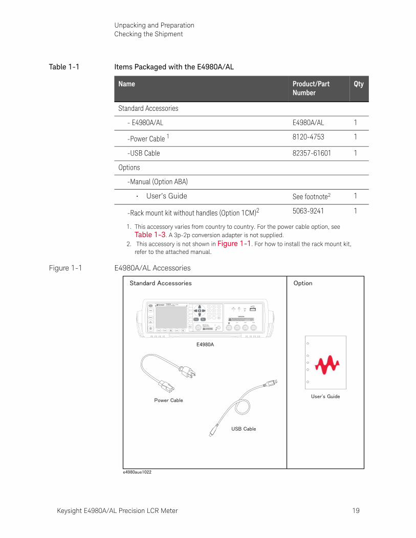
Figure 1-1 E4980A/AL Accessories
Table 1-1 Items Packaged with the E4980A/AL
Name Product/Part Number
Qty
Standard Accessories
- E4980A/AL E4980A/AL 1
-Power Cable 1 8120-4753 1
-USB Cable 82357-61601 1
Options
-Manual (Option ABA)
• User’s Guide See footnote2 1
-Rack mount kit without handles (Option 1CM)2 5063-9241 1
1. This accessory varies from country to country. For the power cable option, see Table 1-3. A 3p-2p conversion adapter is not supplied.
2. This accessory is not shown in Figure 1-1. For how to install the rack mount kit, refer to the attached manual.
E4980APrecision LCR Meter
20 Hz - 2 MHz
LCUR LPOT HPOT HCUR
DCBias USB
DCSource
UNKNOWN
Discharge test device before connecting42V Peak Max Output CAT I
10VDC Max
DC Source(Option 001)
Trigger
DC Bias
DCSource
Return
7 8 9
4 5 6
1 2 3
0 .
Preset
DisplayFormat
MeasSetup
Recall A Recall B Save/Recall System Local/
Lock

20 Keysight E4980A/AL Precision LCR Meter
Unpacking and PreparationPreparations before Use
1-
Preparations before Use
Verifying the Power Supply
Confirm that the power supplied to the E4980A/AL meets the following requirements:
Setting up the Fuse
Please use the following fuse type.
UL/CSA type, Slo-Blo, 520-mm miniature fuse, 3 A, 250 V (Keysight part number 2110-1017)
When you need a fuse, contact your nearest Keysight Technologies sales and service office. To verify and replace the fuse, remove the power cable and pull out the fuse holder.
Figure 1-2 Fuse Holder and Power Cable Receptacle
Table 1-2 Power Supply Requirements
Requirements
Voltage 90 to 132 Vac or 198 to 264 Vac1
Frequency 47 to 63 Hz
Maximum power consumption
150 VA
1. Switched automatically by the E4980A/AL in conformity with the voltage used.
Keysight E4980A/AL Precision LCR Meter 21
Unpacking and PreparationPreparations before Use
Verifying and Connecting the Power Cable
The three-wire power cable attached to the E4980A/AL has one wire serving as a ground. Using this power cable allows the E4980A/AL to be grounded, thereby protecting you against electrical shock from the power outlet.
Step 1. Confirm that the power cable is not damaged.
Step 2. Use the supplied cable to connect the power cable receptacle on the real panel of the E4980A/AL to a three-wire power outlet with the grounding prong firmly held in the ground slot.
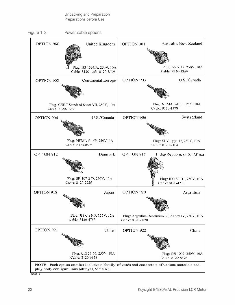
Figure 1-3 shows the power cable options.
Never use a power cable showing any sign of damage. Faulty cables can cause electric shock.
Use the supplied three-wire power cable with a grounding wire to securely ground the E4980A/AL.
A 3p-2p conversion adapter is not supplied with the LCR meter. When you need a 3p-2p conversion adapter, contact your nearest Keysight Technologies sales and service office listed in the back of this manual.
22 Keysight E4980A/AL Precision LCR Meter
Unpacking and PreparationPreparations before Use
1-
Figure 1-3 Power cable options
Keysight E4980A/AL Precision LCR Meter 23
Unpacking and PreparationHow to Remove the Handle
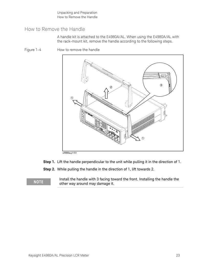
How to Remove the HandleA handle kit is attached to the E4980A/AL. When using the E4980A/AL with the rack-mount kit, remove the handle according to the following steps.
Figure 1-4 How to remove the handle
Step 1. Lift the handle perpendicular to the unit while pulling it in the direction of 1.
Step 2. While pulling the handle in the direction of 1, lift towards 2.
Install the handle with 3 facing toward the front. Installing the handle the other way around may damage it.
24 Keysight E4980A/AL Precision LCR Meter
Unpacking and PreparationCaution when Using the Handle
1-
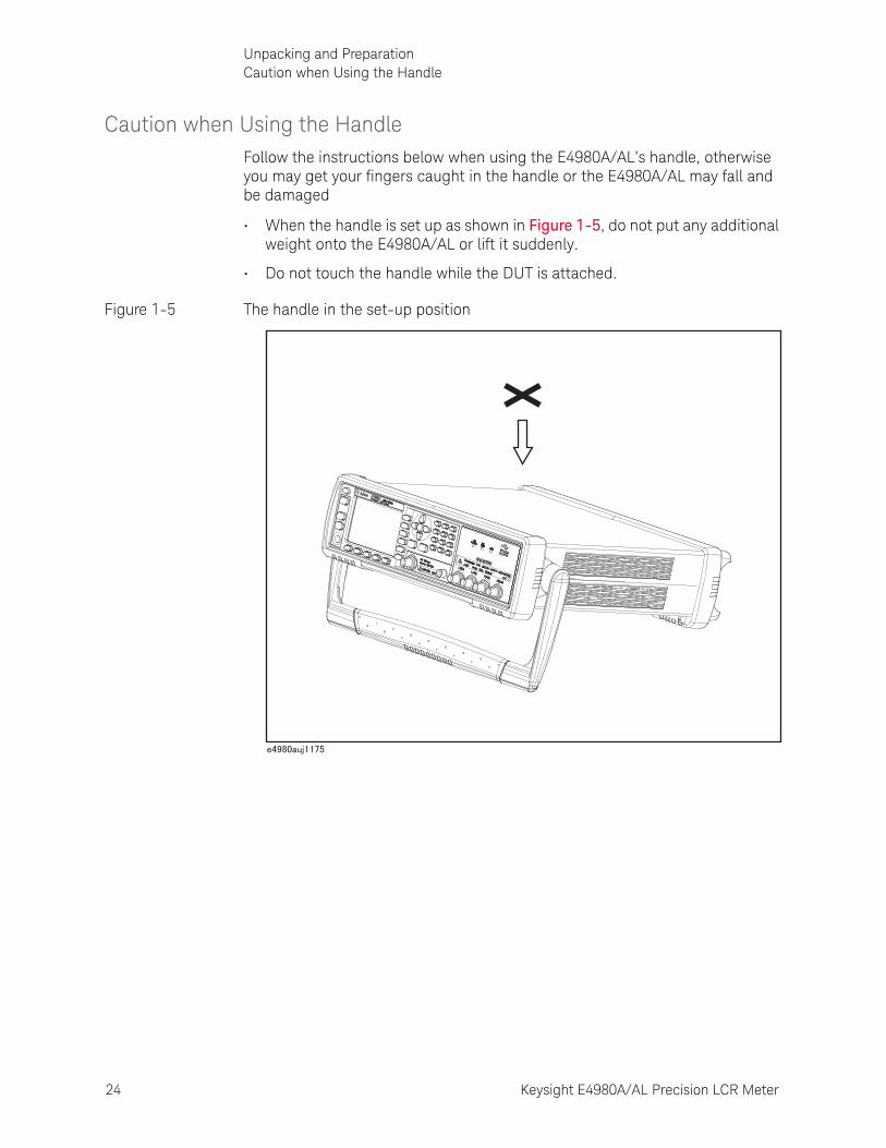
Caution when Using the HandleFollow the instructions below when using the E4980A/AL’s handle, otherwise you may get your fingers caught in the handle or the E4980A/AL may fall and be damaged
• When the handle is set up as shown in Figure 1-5, do not put any additional weight onto the E4980A/AL or lift it suddenly.
• Do not touch the handle while the DUT is attached.
Figure 1-5 The handle in the set-up position

Keysight E4980A/AL Precision LCR Meter 25
Unpacking and PreparationEnvironmental Requirements
Environmental RequirementsSet up the E4980A/AL where the following environmental requirements are satisfied.
Operating Environments
Ensure that the operating environment meets the following requirements.
Table 1-3 Operating Environments Requirements
Temperature 0ºC to 55ºC
Temperature range at calibration
23ºC 5ºC (<1ºC deviation from the temperature when performing calibration)
Humidity 15% to 85% at wet bulb temperature 40ºC (non-condensation)
Altitude 0 to 2,000 m (0 to 6,561 feet)
Vibration Max. 0.5 G, 5 Hz to 500 Hz
The environmental requirements listed above are NOT for the specifications and measurement accuracy of the E4980A/AL, but for its operating environment.
26 Keysight E4980A/AL Precision LCR Meter
Unpacking and PreparationEnvironmental Requirements
1-
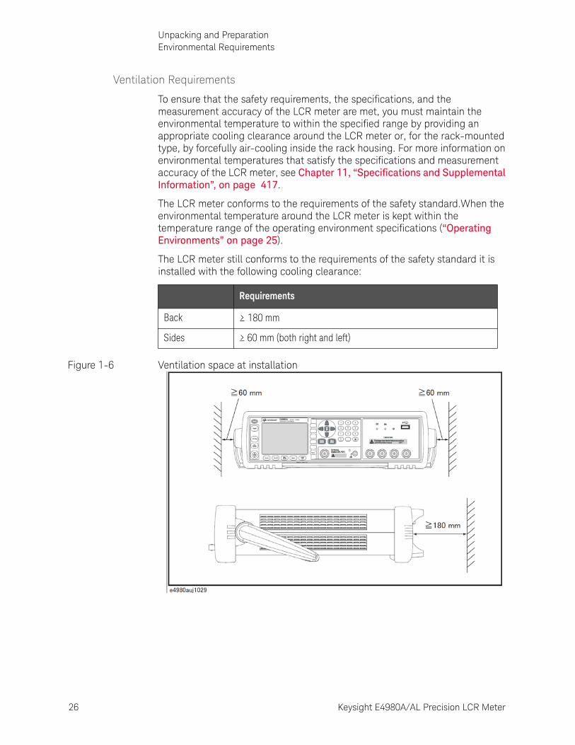
Ventilation Requirements
To ensure that the safety requirements, the specifications, and the measurement accuracy of the LCR meter are met, you must maintain the environmental temperature to within the specified range by providing an appropriate cooling clearance around the LCR meter or, for the rack-mounted type, by forcefully air-cooling inside the rack housing. For more information on environmental temperatures that satisfy the specifications and measurement accuracy of the LCR meter, see Chapter 11, “Specifications and Supplemental Information”, on page 417.
The LCR meter conforms to the requirements of the safety standard.When the environmental temperature around the LCR meter is kept within the temperature range of the operating environment specifications (“Operating Environments” on page 25).
The LCR meter still conforms to the requirements of the safety standard it is installed with the following cooling clearance:
Figure 1-6 Ventilation space at installation
Requirements
Back ≥ 180 mm
Sides ≥ 60 mm (both right and left)
Keysight E4980A/AL Precision LCR Meter 27
Unpacking and PreparationEnvironmental Requirements
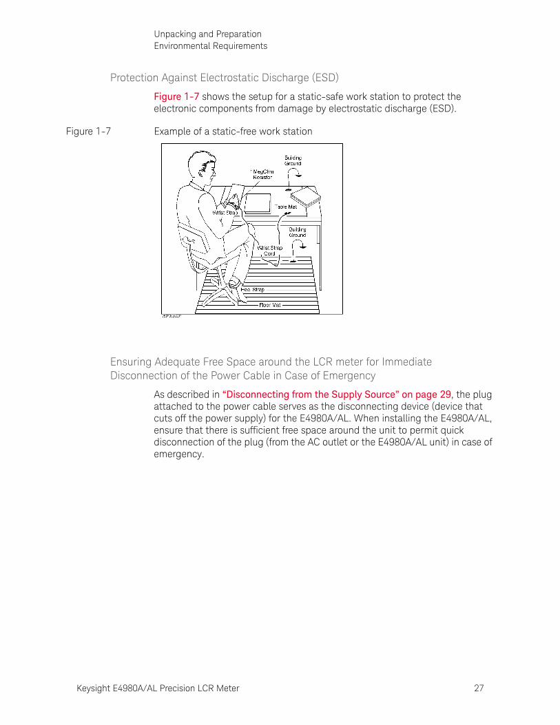
Protection Against Electrostatic Discharge (ESD)
Figure 1-7 shows the setup for a static-safe work station to protect the electronic components from damage by electrostatic discharge (ESD).
Figure 1-7 Example of a static-free work station
Ensuring Adequate Free Space around the LCR meter for Immediate Disconnection of the Power Cable in Case of Emergency
As described in “Disconnecting from the Supply Source” on page 29, the plug attached to the power cable serves as the disconnecting device (device that cuts off the power supply) for the E4980A/AL. When installing the E4980A/AL, ensure that there is sufficient free space around the unit to permit quick disconnection of the plug (from the AC outlet or the E4980A/AL unit) in case of emergency.
28 Keysight E4980A/AL Precision LCR Meter
Unpacking and PreparationStarting the E4980A/AL
1-
Starting the E4980A/ALThis section describes how to turn on/off the E4980A/AL power and how to cut off the power supply in an emergency.
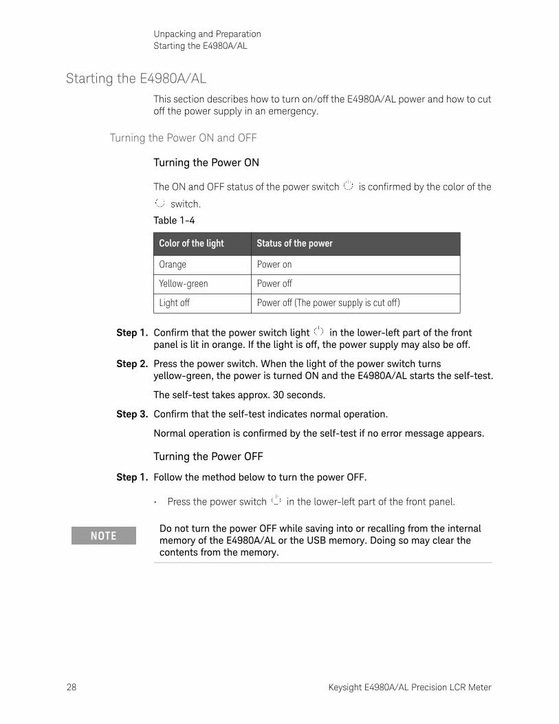
Turning the Power ON and OFF
Turning the Power ON
The ON and OFF status of the power switch is confirmed by the color of the
switch.
Step 1. Confirm that the power switch light in the lower-left part of the front panel is lit in orange. If the light is off, the power supply may also be off.
Step 2. Press the power switch. When the light of the power switch turns yellow-green, the power is turned ON and the E4980A/AL starts the self-test.
The self-test takes approx. 30 seconds.
Step 3. Confirm that the self-test indicates normal operation.
Normal operation is confirmed by the self-test if no error message appears.
Turning the Power OFF
Step 1. Follow the method below to turn the power OFF.
• Press the power switch in the lower-left part of the front panel.
Table 1-4
Color of the light Status of the power
Orange Power on
Yellow-green Power off
Light off Power off (The power supply is cut off )
Do not turn the power OFF while saving into or recalling from the internal memory of the E4980A/AL or the USB memory. Doing so may clear the contents from the memory.
Keysight E4980A/AL Precision LCR Meter 29
Unpacking and PreparationStarting the E4980A/AL
Disconnecting from the Supply Source
The plug attached to the power cable (on the power outlet side or device side of the cable) serves as the disconnecting device (device that cuts off the power supply) of the E4980A/AL. When the power supply must be cut off to avoid such danger as electric shock, pull out the power cable’s plug (on the power outlet side or device side of the cable).
To allow this operation to be performed smoothly, be sure to follow the guidelines in “Ensuring Adequate Free Space around the LCR meter for Immediate Disconnection of the Power Cable in Case of Emergency” on page 27.
When turning the power OFF under normal circumstances, always follow the methods described in “Turning the Power ON and OFF” on page 28.

30 Keysight E4980A/AL Precision LCR Meter
Unpacking and PreparationStarting the E4980A/AL
1-
31
Keysight E4980A/AL Precision LCR Meter
User’s Guide
2 Overview
This chapter provides the basic procedures for operating the E4980A/AL and describes names and functions of the front panel, rear panel, and screen display.
Product IntroductionThe Keysight E4980A/AL is a general-purpose LCR meter for incoming inspection of components, quality control, and laboratory use. The E4980A/AL is used for evaluating LCR components, materials, and semiconductor devices over a wide range of frequencies (20 Hz to 300 kHz/500 kHz/1 MHz/2 MHz) and test signal levels (0.1 mVrms to 2 Vrms, 50 A to 20 mArms). With Option 001, the E4980A’s test signal level range spans 0.1 mV to 20 Vrms, and 50 A to 200 mArms. Also, the E4980A with Option 001 enables up to 40-Vrms DC bias measurements (without Option 001, up to 2 Vrms), DCR measurements, and DC source measurements using the internal voltage source.
The E4980A/AL offers C-D measurement with a basic accuracy of 0.05% (C), 0.0005 (D) at all frequencies with seven-digit resolution (the dissipation factor resolution is 1 ppm) in every range.
With its built-in comparator, the E4980A/AL can output comparison/decision results for sorting components into a maximum of ten bins. Furthermore, by using the handler interface and scanner interface options, the E4980A/AL can be easily combined with a component handler, a scanner, and a system controller to fully automate component testing, sorting, and quality-control data processing.
The E4980A/AL’s list sweep function permits entry of up to 201 frequencies, test signal levels, or bias level points to be automatically measured.
The GP-IB/LAN/USB interfaces are standard interfaces on the E4980A/AL and enable automatic testing.
32 Keysight E4980A/AL Precision LCR Meter
OverviewFront Panel: Names and Functions of Parts
2-
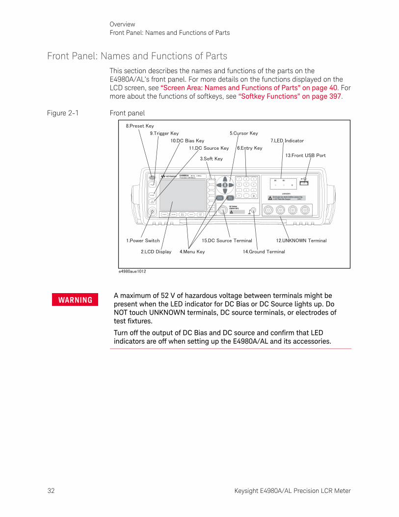
Front Panel: Names and Functions of PartsThis section describes the names and functions of the parts on the E4980A/AL’s front panel. For more details on the functions displayed on the LCD screen, see “Screen Area: Names and Functions of Parts” on page 40. For more about the functions of softkeys, see “Softkey Functions” on page 397.
Figure 2-1 Front panel
A maximum of 52 V of hazardous voltage between terminals might be present when the LED indicator for DC Bias or DC Source lights up. Do NOT touch UNKNOWN terminals, DC source terminals, or electrodes of test fixtures.
Turn off the output of DC Bias and DC source and confirm that LED indicators are off when setting up the E4980A/AL and its accessories.
DCDC
UNKNOWN
Discharge test device before connecting42V Peak Max Output CAT I
DC Source(Option 001)
Trigger
DC Bias
DCSource
Return
7 8 9
4 5 6
1 2 3
0 .
Preset
DisplayFormat
MeasSetup
Recall A Recall B Save/Recall System Local/
Lock
Keysight E4980A/AL Precision LCR Meter 33
OverviewFront Panel: Names and Functions of Parts
1. Power switch
Used for choosing between power-on and -off states of the E4980A/AL. When turned on, the switch lights up in yellow-green and all operating voltages are applied to the instrument. When turned off, the switch lights up in orange and no operating voltages are applied to the instrument.
2. LCD
The Liquid Crystal Display (LCD) displays measurement results, test conditions, etc.
3. Softkeys
Five softkeys are used to select measurement conditions and parameter functions. Each softkey has a softkey label along its left side.
4. Menu keys
Menu selection keys are used to access the corresponding selection of instrument controls.
5. Cursor keys
Keys used to move the field select cursor from field to field on a displayed page. When the cursor is moved to a certain field, that field changes to an inverse video image of the original field. The cursor can only be moved from field to field.
For the skip key, refer to the “How to Use Skip Keys” on page 44.
Occasionally there are missing pixels or constantly lit pixels, but this is not a malfunction and does not affect the performance of your product.
Table 2-1 Menu Keys
[Display Format] key Displays measurement results and selections.
[Meas Setup] key Sets measurement conditions, a correction function, and limit values for BIN sorting.
[Recall A] key Recalls the setting information on internal memory 0.
[Recall B] key Recalls the setting information on internal memory 1.
[Save/Recall] key Saves and recalls the setting information. Saves measurement results and screen images.
[System] key Sets the system. Sets the GP-IB interface and LAN. Performs a self-test.
[Local/Lock] key Locks and unlocks hard keys and softkeys on the front panel. Cancels remote control with GPIB commands.
34 Keysight E4980A/AL Precision LCR Meter
OverviewFront Panel: Names and Functions of Parts
2-
6. Entry keys
Keys used to enter numeric data into the E4980A/AL. The entry keys comprise the digits 0 to 9, a period (.), and a plus/minus (+/-) sign. Entered values are displayed on the input line (second line from the bottom of the LCD screen), and pressing the softkey terminates numeric input. The plus/minus key deletes the last character of the input value.
7. LED indicator
The LED indicator lights up when DC Bias or DC Source is on. The USB indicator lights up while accessing a USB memory.
8. Preset key
A key used to return the LCR meter to the initial setup state. There are three methods for initialization. For details, refer to “Initializing the Instrument” on page 87.
9. Trigger key
A key used to manually trigger the E4980A/AL when it is set to the manual trigger mode.
10. DC Bias key
A key used to toggle on and off of the DC bias output. When the DC bias output is set to on, the DC bias indicator lights up and DCBIAS is displayed in the status display area on the screen.
If the DC Bias key is set to off, even though the DC bias is set to on according to the LCD display, the DC bias is not output.
11. DC Source key
A key used to toggle on and off of the DC source output. When the DC source output is set to on, the DC Source indicator lights up and DCSRC is displayed in the status display area on the screen.
Regardless of which page is displayed, when the DC BIAS key is pressed, the value that has been set in the BIAS field of MEAS SETUP (and MEAS DISPLAY) is output. For example, in case that DC Bias sweep has been set with the LIST SWEEP DISPLAY page displayed, the value set in the BIAS field is output when the DC BIAS key is pressed. Then, after the E4980A/AL is triggered, the DC Bias is set according to the list that has been set.
Option 001 is required for this function.
Keysight E4980A/AL Precision LCR Meter 35
OverviewFront Panel: Names and Functions of Parts
12. UNKNOWN terminals
These are the UNKNOWN terminals used to connect a four-terminal pair test fixture or test leads for measuring the device under test (DUT).
The maximum load the UNKNOWN terminals can withstand is 10 kgf (nominal).
The test ports comply with Installation Category I of IEC 61010-1.
13. Front USB port
This port is used to save data in a USB memory. The USB indicator lights up while accessing the USB memory.
Connector types: Universal Serial Bus (USB) Jack, Type A (four contact points), Female.
Compliance Standards: USB 1.1
Regardless of which page is displayed, when the DC SOURCE key is pressed, the value that has been set in the DC SRC field of MEAS SETUP is output. For example, in case that DC SRC sweep has been set with the LIST SWEEP DISPLAY page displayed, the value set in the DC SRC field is output when the DC SRC key is pressed. Then, after the E4980A/AL is triggered, the DC Source is set according to the list that has been set.
When using a four-terminal pair test fixture or test leads with a stopper, remove the stopper or the bumper of the E4980A/AL.
Do not apply DC voltage or current to the UNKNOWN terminals. Applying DC voltage or current may lead to device failure. Connect the measurement sample (DUT) to the test port (or the test fixture, cables, etc. connected to the test port) after the LCR meter has been completely discharged.
Do not connect any device other than a USB memory to the USB port. We do not support connections to the USB port of printers, devices with a built-in HDD, or USB hubs. To print a screen, refer to “To save a screenshot into USB memory” on page 188.
Do not unplug the USB memory while the USB indicator is on.
36 Keysight E4980A/AL Precision LCR Meter
OverviewFront Panel: Names and Functions of Parts
2-
USB memory type
Use USB memory that is USB mass-storage-class compliant and formatted with FAT16 or FAT32. For points to notice, refer to “USB Memory Notes” on page 173.
Interface: USB 1.1
14. Ground terminal
Connected to the chassis of the E4980A/AL. This is used for measurements that require guarding.
15. DC Source terminal
Outputs the DC source in the range from -10 V to 10 V. Option 001 is required for this function.
The DC source terminal is installed even in the E4980A/AL without Option 001; however, the E4980A/AL without Option 001 cannot use this terminal.

Keysight E4980A/AL Precision LCR Meter 37
OverviewRear Panel: Names and Functions of Parts
Rear Panel: Names and Functions of PartsThis section describes the names and functions of the parts on the E4980A/AL’s rear panel.
Figure 2-2 Rear panel
1. GPIB Interface Connector
General Purpose Interface Bus (GPIB). The connection of an external controller and other devices through this connector allows you to configure an automatic measurement system.
2. Interface Connector
If interface options are installed, the interface connectors will be installed as shown. If the E4980A/AL is not equipped with an interface option, blank panels will cover this portion.
Interfaces with which the E4980A/AL can be equipped as options are shown below.
Handler interface (Option E4980A/AL-201)
This interface is for data exchange with an automatic machine (handler) used on a production line.
Connector type: 36-pin Centronics
38 Keysight E4980A/AL Precision LCR Meter
OverviewRear Panel: Names and Functions of Parts
2-
Scanner interface (Option E4980A/AL-301)
The interface to connect a scanner to perform up to 128 sets of multi-channel corrections and measurements.
Connector type: 14-pin Amphenol
3. USB (USBTMC) Interface Port
Through this port, you can control the E4980A/AL via external controllers.
Connector Types: Universal Serial Bus (USB) jack, type mini-B (five contact points), Female
Compliance Standards: USBTMC-USB488 and USB2.0
4. LAN Port
The port to connect the E4980A/AL to a LAN (Local Area Network). Connecting this instrument to a LAN enables you to control this instrument by using SICL-LAN or telnet, or from an external PC via a Web server.
This is compliant with LXI standard (LAN eXtensions for Instrumentation): version 1.4 Class C.
Connector type: 8-pin RJ-45 connectorCompliance Standard: 10Base-T/100Base-TX Ethernet (automatic data rate selection)
5. External Trigger Input Connector
The BNC connector to input the positive TTL pulse to trigger the E4980A/AL with external trigger signals.(The trigger mode must be set to EXTernal.)
6. Serial Number Plate
The seal showing the product’s serial number.
Auto-MDIX function is effective on S/N MY4620XXX or later.
Keysight E4980A/AL Precision LCR Meter 39
OverviewRear Panel: Names and Functions of Parts
7. Power Cable Receptacle (to LINE)
The receptacle (outlet) to which the power cable is connected.
For more on the power supply, see “Verifying and Connecting the Power Cable” on page 21.
8. Fan
The cooling fan for controlling the temperature inside the E4980A/AL. This fan extracts heated air from inside the LCR meter.
To connect the device to a power source (outlet), use the supplied three-prong power cable with a ground conductor.
The plug attached to the power cable (on the power outlet side or device side of the cable) serves as the E4980A/AL’s disconnecting device (device that cuts off the power supply). When the power supply must be cut off to avoid such danger as electric shock, pull out the power cable plug (on the power outlet side or device side of the cable). For the procedure for turning off the power in normal use, see the description in “1. Power switch” on page 33.
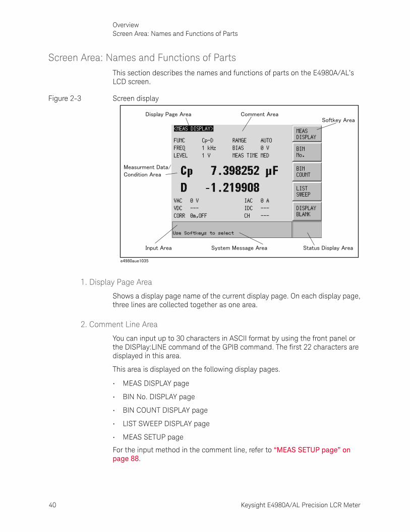
40 Keysight E4980A/AL Precision LCR Meter
OverviewScreen Area: Names and Functions of Parts
2-
Screen Area: Names and Functions of PartsThis section describes the names and functions of parts on the E4980A/AL’s LCD screen.
Figure 2-3 Screen display
1. Display Page Area
Shows a display page name of the current display page. On each display page, three lines are collected together as one area.
2. Comment Line Area
You can input up to 30 characters in ASCII format by using the front panel or the DISPlay:LINE command of the GPIB command. The first 22 characters are displayed in this area.
This area is displayed on the following display pages.
• MEAS DISPLAY page
• BIN No. DISPLAY page
• BIN COUNT DISPLAY page
• LIST SWEEP DISPLAY page
• MEAS SETUP page
For the input method in the comment line, refer to “MEAS SETUP page” on page 88.
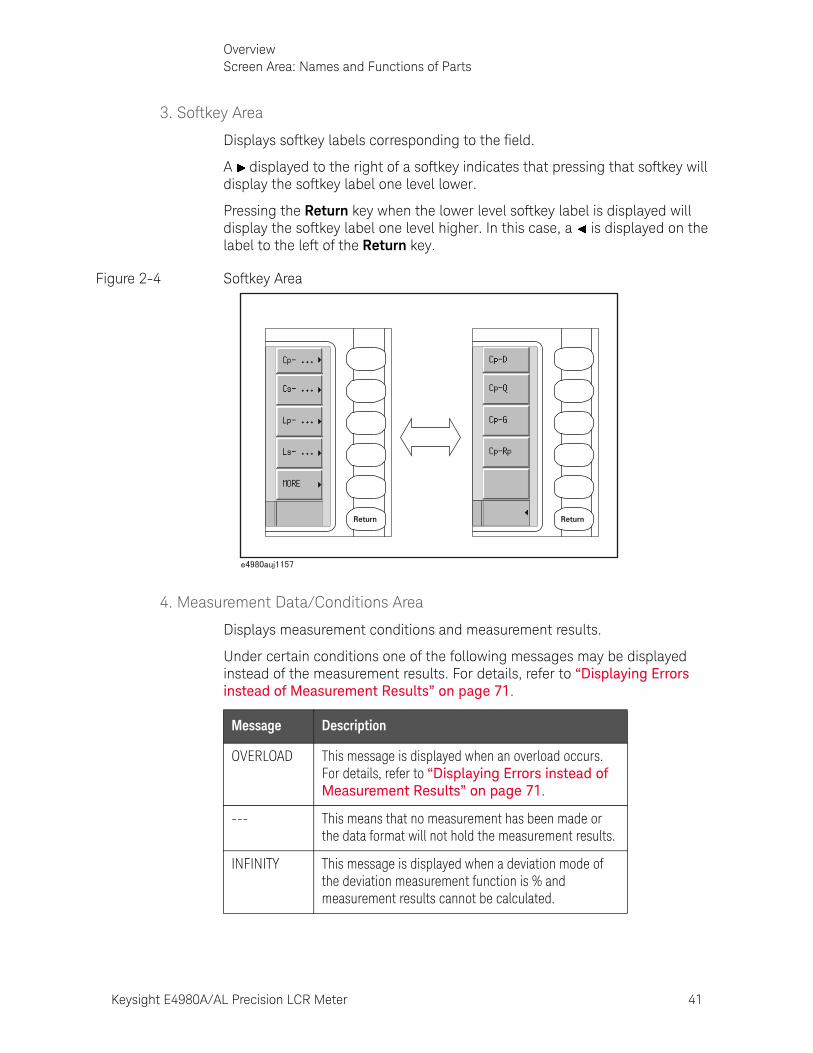
Keysight E4980A/AL Precision LCR Meter 41
OverviewScreen Area: Names and Functions of Parts
3. Softkey Area
Displays softkey labels corresponding to the field.
A displayed to the right of a softkey indicates that pressing that softkey will display the softkey label one level lower.
Pressing the Return key when the lower level softkey label is displayed will display the softkey label one level higher. In this case, a is displayed on the label to the left of the Return key.
Figure 2-4 Softkey Area
4. Measurement Data/Conditions Area
Displays measurement conditions and measurement results.
Under certain conditions one of the following messages may be displayed instead of the measurement results. For details, refer to “Displaying Errors instead of Measurement Results” on page 71.
Return Return
Message Description
OVERLOAD This message is displayed when an overload occurs. For details, refer to “Displaying Errors instead of Measurement Results” on page 71.
--- This means that no measurement has been made or the data format will not hold the measurement results.
INFINITY This message is displayed when a deviation mode of the deviation measurement function is % and measurement results cannot be calculated.
42 Keysight E4980A/AL Precision LCR Meter
OverviewScreen Area: Names and Functions of Parts
2-
5. Input Line Area
Displays numeric values entered with the entry key.
6. System Message Area
Displays a system message, warning, and error message.
7. Status Display Area
Displays the status when DC bias or DC source is on, or any front panel key is locked. When sending SCPI commands from the external controller, “RMT” is displayed and the front panel keys are locked.
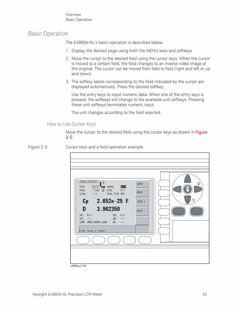
Keysight E4980A/AL Precision LCR Meter 43
OverviewBasic Operation
Basic OperationThe E4980A/AL’s basic operation is described below.
1. Display the desired page using both the MENU keys and softkeys.
2. Move the cursor to the desired field using the cursor keys. When the cursor is moved to a certain field, the field changes to an inverse video image of the original. The cursor can be moved from field to field (right and left or up and down).
3. The softkey labels corresponding to the field indicated by the cursor are displayed automatically. Press the desired softkey.
Use the entry keys to input numeric data. When one of the entry keys is pressed, the softkeys will change to the available unit softkeys. Pressing these unit softkeys terminates numeric input.
The unit changes according to the field selected.
How to Use Cursor Keys
Move the cursor to the desired field using the cursor keys as shown in Figure 2-5.
Figure 2-5 Cursor keys and a field operation example

44 Keysight E4980A/AL Precision LCR Meter
OverviewBasic Operation
2-
How to Use Skip Keys
The following describes how to use a skip key.
On a display page, three lines are collected together as one. By using a skip key, you can select the desired field quickly as the selected field moves from area to area.
Figure 2-6 Skip key and a field operation example
Return
45
Keysight E4980A/AL Precision LCR Meter
User’s Guide
3 Display Format
This chapter describes each page of the DISPLAY FORMAT MENU of the E4980A/AL.
MEAS DISPLAY PageWhen you press the [DISPLAY FORMAT] key, the MEAS DISPLAY page appears. The following measurement controls can be set on this page (The field in parenthesis is used to set measurement controls).
• Measurement Function (FUNC)
• Impedance range (RANGE)
• Test Frequency (FREQ)
• Test Signal Level (LEVEL)
• DC Bias (BIAS)
• Measurement Time Mode (MEAS TIME)
Figure 3-1 shows the available fields and the softkeys that correspond to the fields on this page.
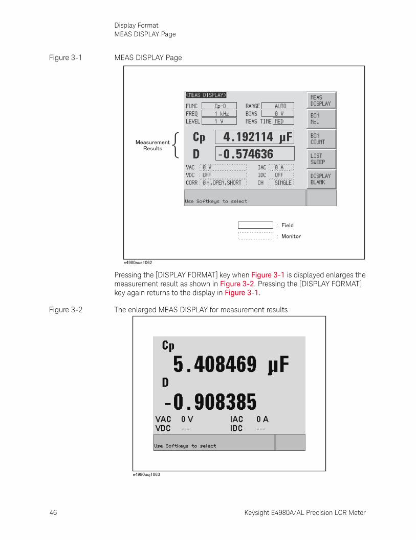
46 Keysight E4980A/AL Precision LCR Meter
Display FormatMEAS DISPLAY Page
3-
Figure 3-1 MEAS DISPLAY Page
Pressing the [DISPLAY FORMAT] key when Figure 3-1 is displayed enlarges the measurement result as shown in Figure 3-2. Pressing the [DISPLAY FORMAT] key again returns to the display in Figure 3-1.
Figure 3-2 The enlarged MEAS DISPLAY for measurement results

Keysight E4980A/AL Precision LCR Meter 47
Display FormatMEAS DISPLAY Page
Measurement Function
The E4980A/AL simultaneously measures two components of the complex impedance (parameters) in a measurement cycle.
Regardless of the types of measurement parameters, the test signal voltage (VAC) and the test signal current (IAC) are measured at the same time. When the E4980A is equipped with option 001, the DC bias voltage level (VDC) and the DC bias current level (IDC) are measured simultaneously.
DC resistance (Rdc) can be measured when the E4980A/AL is equipped with either option 001, 030/032, 050/052, 100/102, or 200,
DC voltage (Vdc), and DC current (Idc) can be measured when the E4980A is equipped with option 001.
Types of measurement parameters
Types of measurement parameters are shown below.
Regardless of the types of measurement parameters, the measurement result for the R-X parameter can be obtained using the SCPI command.
Table 3-1 Measurement parameters
Primary parameter Secondary parameter
Cp D, Q, G, Rp
Cs D, Q, Rs
Lp D, Q, G, Rp, Rdc1
Ls D, Q, Rs, Rdc1
R X
Z d, r
G B
Y d, r
Vdc2 Idc2
1. This parameter can be set only when the E4980A/AL is equipped with either option 001, 030/032, 050/052, 100 or 200.
2. This parameter can be set only when the E4980A is equipped with option 001.
When the measurement parameter is DC voltage measurement/DC current measurement (Vdc-Idc), set the setting value of the test signal level (LEVEL field) to 0 V for accurate measurement.
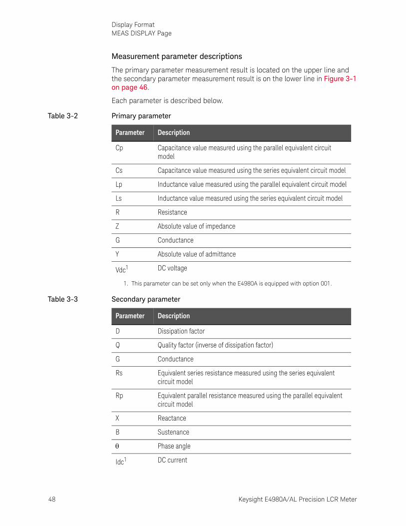
48 Keysight E4980A/AL Precision LCR Meter
Display FormatMEAS DISPLAY Page
3-
Measurement parameter descriptions
The primary parameter measurement result is located on the upper line and the secondary parameter measurement result is on the lower line in Figure 3-1 on page 46.
Each parameter is described below.
Table 3-2 Primary parameter
Parameter Description
Cp Capacitance value measured using the parallel equivalent circuit model
Cs Capacitance value measured using the series equivalent circuit model
Lp Inductance value measured using the parallel equivalent circuit model
Ls Inductance value measured using the series equivalent circuit model
R Resistance
Z Absolute value of impedance
G Conductance
Y Absolute value of admittance
Vdc1 DC voltage
1. This parameter can be set only when the E4980A is equipped with option 001.
Table 3-3 Secondary parameter
Parameter Description
D Dissipation factor
Q Quality factor (inverse of dissipation factor)
G Conductance
Rs Equivalent series resistance measured using the series equivalent circuit model
Rp Equivalent parallel resistance measured using the parallel equivalent circuit model
X Reactance
B Sustenance
Phase angle
Idc1 DC current
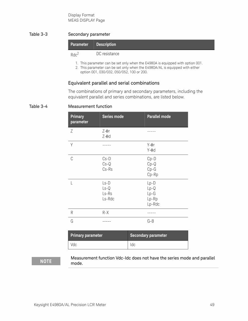
Keysight E4980A/AL Precision LCR Meter 49
Display FormatMEAS DISPLAY Page
Equivalent parallel and serial combinations
The combinations of primary and secondary parameters, including the equivalent parallel and series combinations, are listed below.
Rdc2 DC resistance
1. This parameter can be set only when the E4980A is equipped with option 001.2. This parameter can be set only when the E4980A/AL is equipped with either
option 001, 030/032, 050/052, 100 or 200.
Table 3-3 Secondary parameter
Parameter Description
Table 3-4 Measurement function
Primary parameter
Series mode Parallel mode
Z Z-rZ-d
-----
Y ----- Y-rY-d
C Cs-DCs-QCs-Rs
Cp-DCp-QCp-GCp-Rp
L Ls-DLs-QLs-RsLs-Rdc
Lp-DLp-QLp-GLp-RpLp-Rdc
R R-X -----
G ----- G-B
Primary parameter Secondary parameter
Vdc Idc
Measurement function Vdc-Idc does not have the series mode and parallel mode.
50 Keysight E4980A/AL Precision LCR Meter
Display FormatMEAS DISPLAY Page
3-
Procedure for setting the measurement function
Step 1. Press the [Display Format] key.
Step 2. Press the MEAS DISPLAY softkey.
Step 3. Use the cursor keys to select the FUNC field.
Step 4. Use the softkeys to select the primary parameter.
Step 5. If the secondary parameter exists, select the secondary parameter from measurement parameters displayed using the softkeys.
For the combinations of measurement parameters, refer to Table 3-1 on page 47.
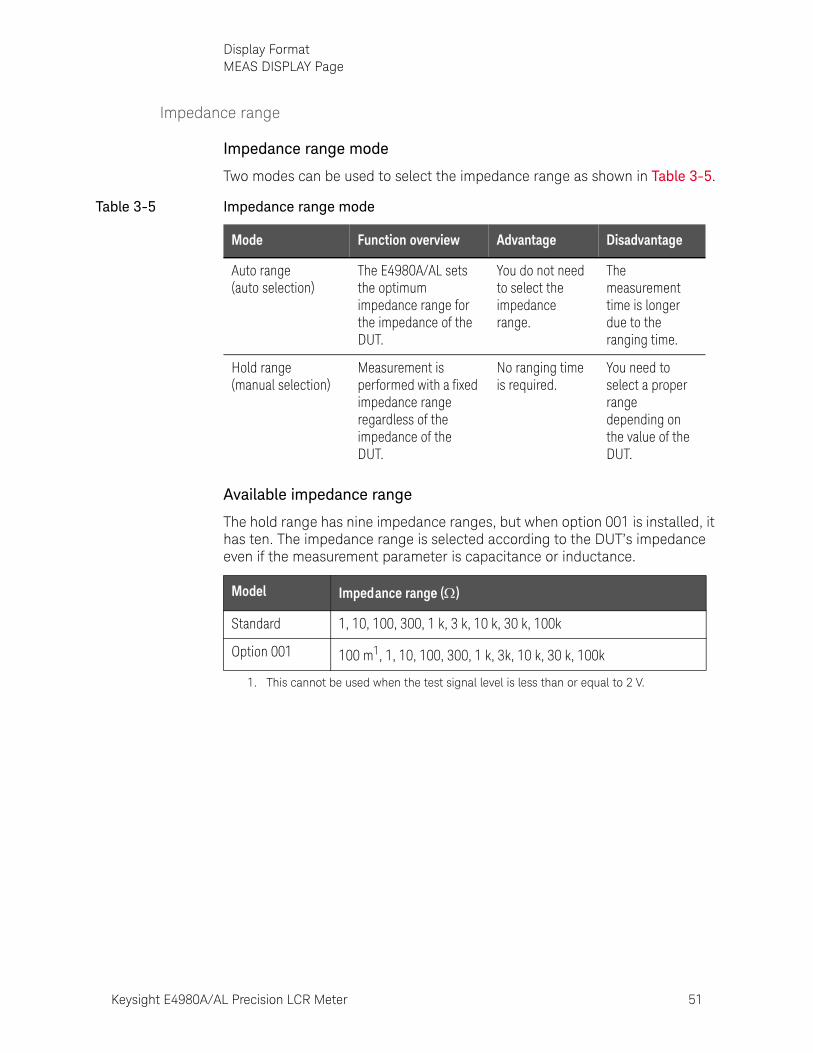
Keysight E4980A/AL Precision LCR Meter 51
Display FormatMEAS DISPLAY Page
Impedance range
Impedance range mode
Two modes can be used to select the impedance range as shown in Table 3-5.
Available impedance range
The hold range has nine impedance ranges, but when option 001 is installed, it has ten. The impedance range is selected according to the DUT’s impedance even if the measurement parameter is capacitance or inductance.
Table 3-5 Impedance range mode
Mode Function overview Advantage Disadvantage
Auto range (auto selection)
The E4980A/AL sets the optimum impedance range for the impedance of the DUT.
You do not need to select the impedance range.
The measurement time is longer due to the ranging time.
Hold range(manual selection)
Measurement is performed with a fixed impedance range regardless of the impedance of the DUT.
No ranging time is required.
You need to select a proper range depending on the value of the DUT.
Model Impedance range ()
Standard 1, 10, 100, 300, 1 k, 3 k, 10 k, 30 k, 100k
Option 001 100 m1, 1, 10, 100, 300, 1 k, 3k, 10 k, 30 k, 100k
1. This cannot be used when the test signal level is less than or equal to 2 V.
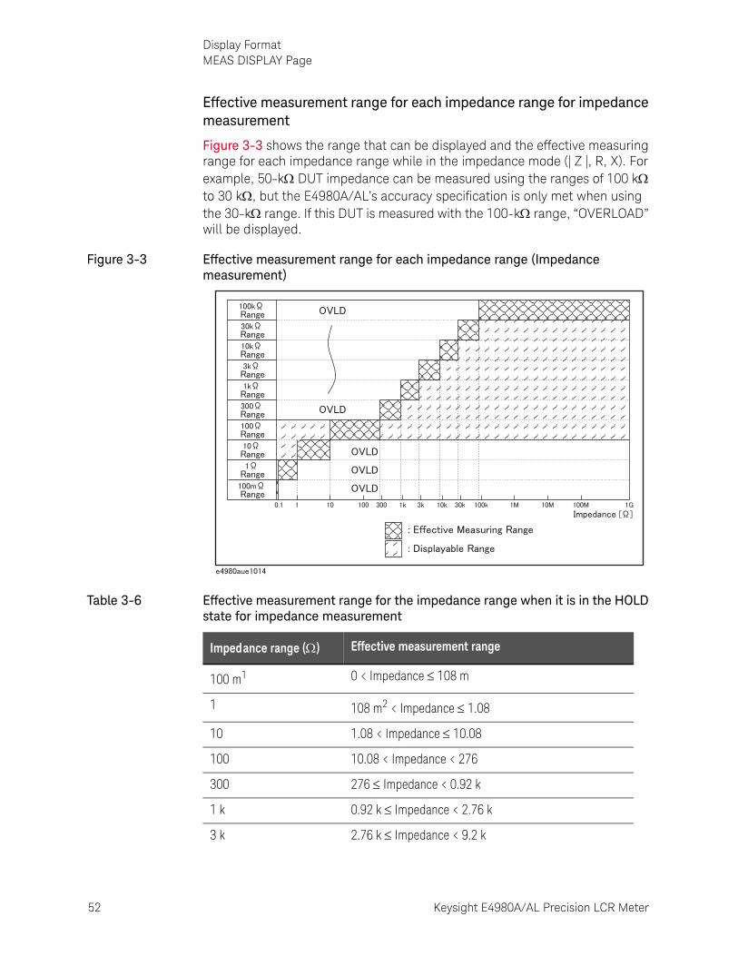
52 Keysight E4980A/AL Precision LCR Meter
Display FormatMEAS DISPLAY Page
3-
Effective measurement range for each impedance range for impedance measurement
Figure 3-3 shows the range that can be displayed and the effective measuring range for each impedance range while in the impedance mode (| Z |, R, X). For example, 50-k DUT impedance can be measured using the ranges of 100 k to 30 k, but the E4980A/AL’s accuracy specification is only met when using the 30-k range. If this DUT is measured with the 100-k range, “OVERLOAD” will be displayed.
Figure 3-3 Effective measurement range for each impedance range (Impedance measurement)
Table 3-6 Effective measurement range for the impedance range when it is in the HOLD state for impedance measurement
Impedance range () Effective measurement range
100 m1 0 < Impedance 108 m
1 108 m2 < Impedance 1.08
10 1.08 < Impedance 10.08
100 10.08 < Impedance < 276
300 276 Impedance < 0.92 k
1 k 0.92 k Impedance < 2.76 k
3 k 2.76 k Impedance < 9.2 k
Keysight E4980A/AL Precision LCR Meter 53
Display FormatMEAS DISPLAY Page
Effective measurement range for each impedance range
The following shows the effective measurement range of each impedance range, in which the E4980A/AL’s measurement accuracy meets its specifications.
When the impedance range is set manually, the optimum impedance range should be selected by matching the impedance of the DUT to the effective measurement range shown in Figure 3-4, Figure 3-5, and Figure 3-6. When the impedance range is set to AUTO, the optimum impedance range is automatically selected according to the impedance of each DUT.
10 k 9.2 k Impedance < 27.6 k3
30 k 27.6 k Impedance < 92 k4
100 k 92 k Impedance
1. This can be set when the test signal level is more than 2 V.2. When the test signal level is less than or equal to 2 V or 20 mA, it is 0 (zero).3. When test frequency is more than 100 kHz and the test signal level is less than
or equal to 0.2 V (2 mA), it is more than 9.2 k.4. When test frequency is more than 100 kHz and the test signal level is more than
0.2 V and less than or equal to 2 V (more than 2 mA and less than or equal to 20 mA), it is more than 27.6 k.
Table 3-6 Effective measurement range for the impedance range when it is in the HOLD state for impedance measurement
Impedance range () Effective measurement range
The impedance range is limited by the test frequency setting when the test signal level is less than or equal to 2V. When the impedance range and test frequency are set under the above conditions, the test frequency must be set first, followed by the impedance range. If you set the impedance range first and then frequency, the resulting impedance range may not be the one you wanted to set.
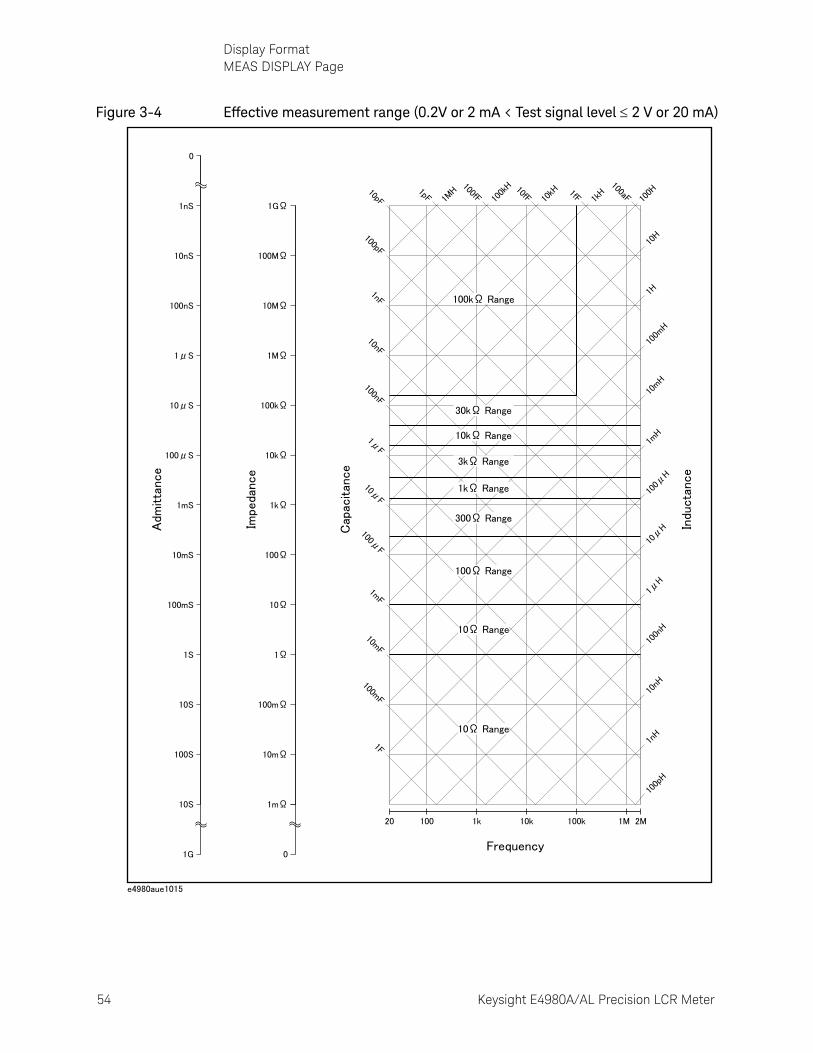
54 Keysight E4980A/AL Precision LCR Meter
Display FormatMEAS DISPLAY Page
3-
Figure 3-4 Effective measurement range (0.2V or 2 mA < Test signal level 2 V or 20 mA)
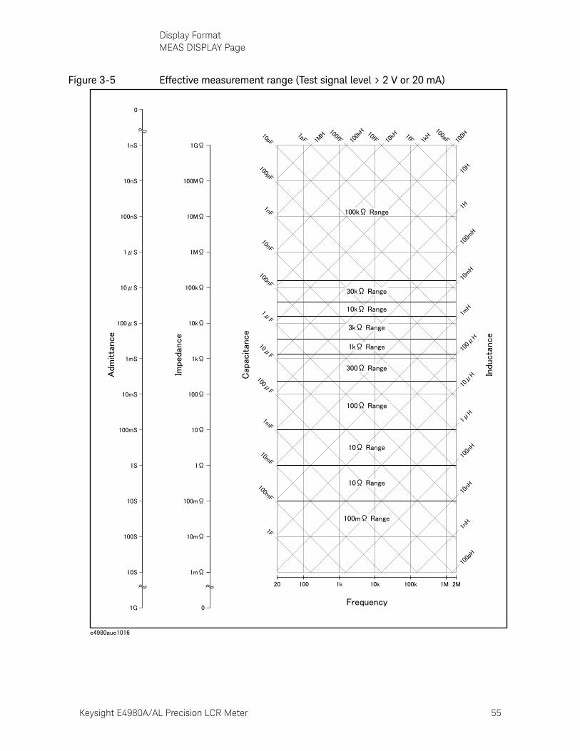
Keysight E4980A/AL Precision LCR Meter 55
Display FormatMEAS DISPLAY Page
Figure 3-5 Effective measurement range (Test signal level > 2 V or 20 mA)
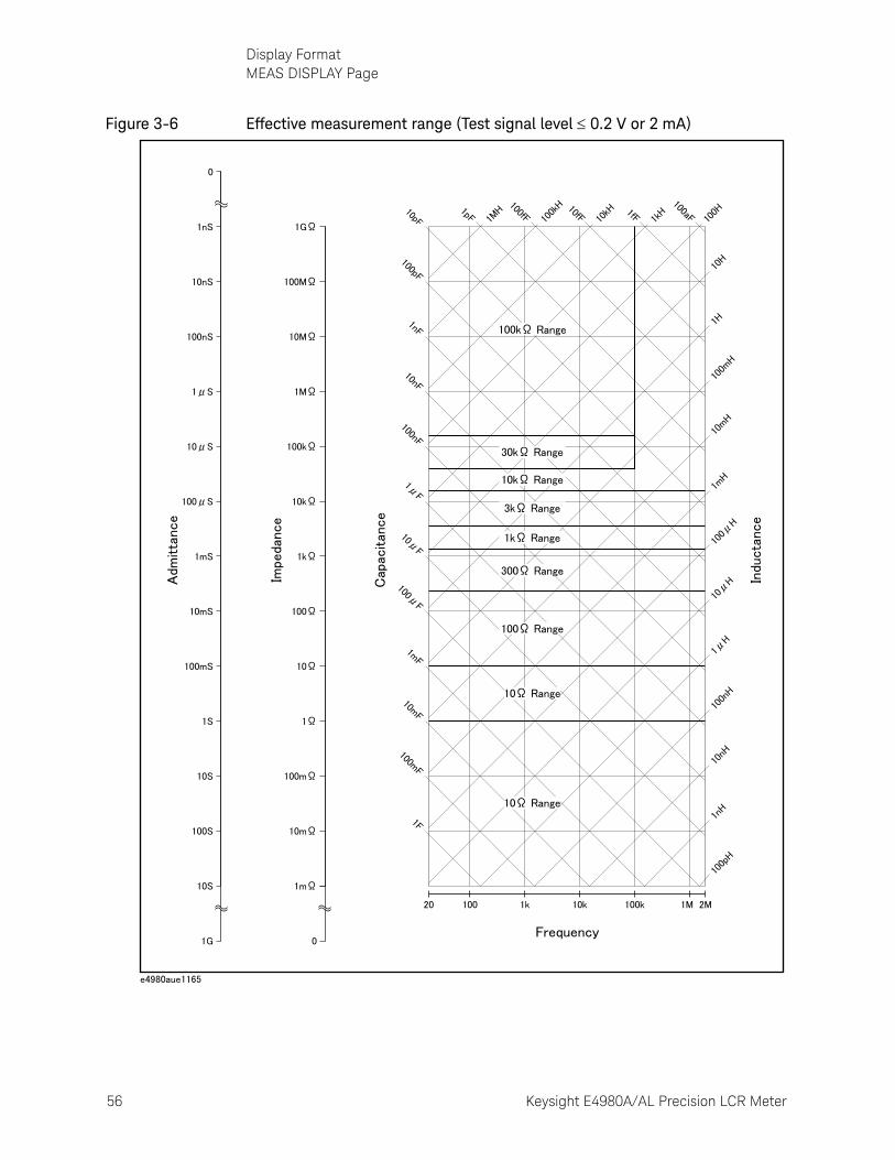
56 Keysight E4980A/AL Precision LCR Meter
Display FormatMEAS DISPLAY Page
3-
Figure 3-6 Effective measurement range (Test signal level 0.2 V or 2 mA)
Keysight E4980A/AL Precision LCR Meter 57
Display FormatMEAS DISPLAY Page
Procedure for setting the impedance range
Step 1. Press the [Display Format] key.
Step 2. Press the MEAS DISPLAY softkey.
Step 3. Use the cursor keys to select the RANGE field.
Step 4. Use the softkeys to select the impedance range mode or impedance range.
Manually setting the time for the impedance range mode
Changing impedance range requires a few milliseconds to several tens of milliseconds. For details, refer to Settling Time in data sheet in Chapter 11 “Specifications and Supplemental Information”
Softkey Function
AUTO Sets the impedance range mode to AUTO.
HOLD Sets the impedance range mode to HOLD.
INCR + Increments the impedance range in the HOLD mode.
DECR - Decrements the impedance range in the HOLD mode.
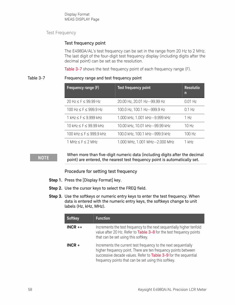
58 Keysight E4980A/AL Precision LCR Meter
Display FormatMEAS DISPLAY Page
3-
Test Frequency
Test frequency point
The E4980A/AL’s test frequency can be set in the range from 20 Hz to 2 MHz. The last digit of the four-digit test frequency display (including digits after the decimal point) can be set as the resolution.
Table 3-7 shows the test frequency point of each frequency range (F).
Procedure for setting test frequency
Step 1. Press the [Display Format] key.
Step 2. Use the cursor keys to select the FREQ field.
Step 3. Use the softkeys or numeric entry keys to enter the test frequency. When data is entered with the numeric entry keys, the softkeys change to unit labels (Hz, kHz, MHz).
Table 3-7 Frequency range and test frequency point
Frequency range (F) Test frequency point Resolution
20 Hz F 99.99 Hz 20.00 Hz, 20.01 Hz•••99.99 Hz 0.01 Hz
100 Hz F 999.9 Hz 100.0 Hz, 100.1 Hz•••999.9 Hz 0.1 Hz
1 kHz F 9.999 kHz 1.000 kHz, 1.001 kHz•••9.999 kHz 1 Hz
10 kHz F 99.99 kHz 10.00 kHz, 10.01 kHz•••99.99 kHz 10 Hz
100 kHz F 999.9 kHz 100.0 kHz, 100.1 kHz•••999.9 kHz 100 Hz
1 MHz F 2 MHz 1.000 MHz, 1.001 MHz•••2.000 MHz 1 kHz
When more than five-digit numeric data (including digits after the decimal point) are entered, the nearest test frequency point is automatically set.
Softkey Function
INCR ++ Increments the test frequency to the next sequentially higher tenfold value after 20 Hz. Refer to Table 3-8 for the test frequency points that can be set using this softkey.
INCR + Increments the current test frequency to the next sequentially higher frequency point. There are ten frequency points between successive decade values. Refer to Table 3-9 for the sequential frequency points that can be set using this softkey.
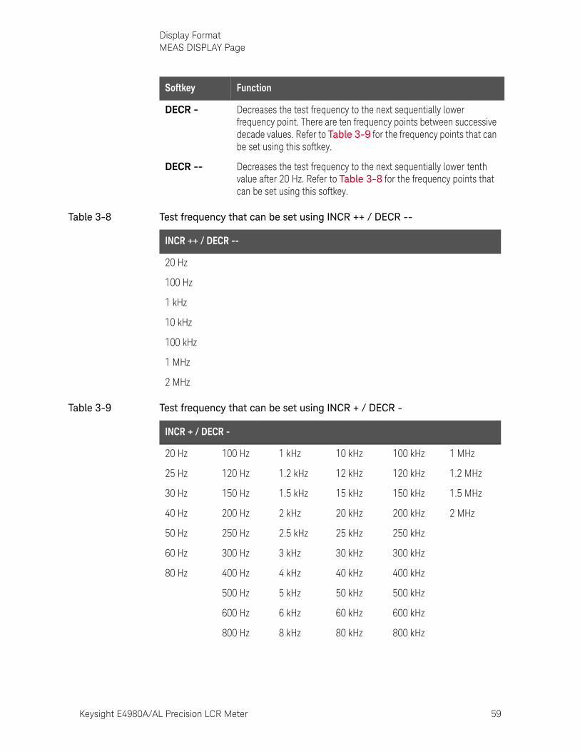
Keysight E4980A/AL Precision LCR Meter 59
Display FormatMEAS DISPLAY Page
DECR - Decreases the test frequency to the next sequentially lower frequency point. There are ten frequency points between successive decade values. Refer to Table 3-9 for the frequency points that can be set using this softkey.
DECR -- Decreases the test frequency to the next sequentially lower tenth value after 20 Hz. Refer to Table 3-8 for the frequency points that can be set using this softkey.
Table 3-8 Test frequency that can be set using INCR ++ / DECR --
INCR ++ / DECR --
20 Hz
100 Hz
1 kHz
10 kHz
100 kHz
1 MHz
2 MHz
Table 3-9 Test frequency that can be set using INCR + / DECR -
INCR + / DECR -
20 Hz 100 Hz 1 kHz 10 kHz 100 kHz 1 MHz
25 Hz 120 Hz 1.2 kHz 12 kHz 120 kHz 1.2 MHz
30 Hz 150 Hz 1.5 kHz 15 kHz 150 kHz 1.5 MHz
40 Hz 200 Hz 2 kHz 20 kHz 200 kHz 2 MHz
50 Hz 250 Hz 2.5 kHz 25 kHz 250 kHz
60 Hz 300 Hz 3 kHz 30 kHz 300 kHz
80 Hz 400 Hz 4 kHz 40 kHz 400 kHz
500 Hz 5 kHz 50 kHz 500 kHz
600 Hz 6 kHz 60 kHz 600 kHz
800 Hz 8 kHz 80 kHz 800 kHz
Softkey Function

60 Keysight E4980A/AL Precision LCR Meter
Display FormatMEAS DISPLAY Page
3-
Time required for setting the test frequency
Changing the test frequency requires a few milliseconds to several tens of milliseconds. For details, refer to Settling Time in data sheet in Chapter 11 “Specifications and Supplemental Information”
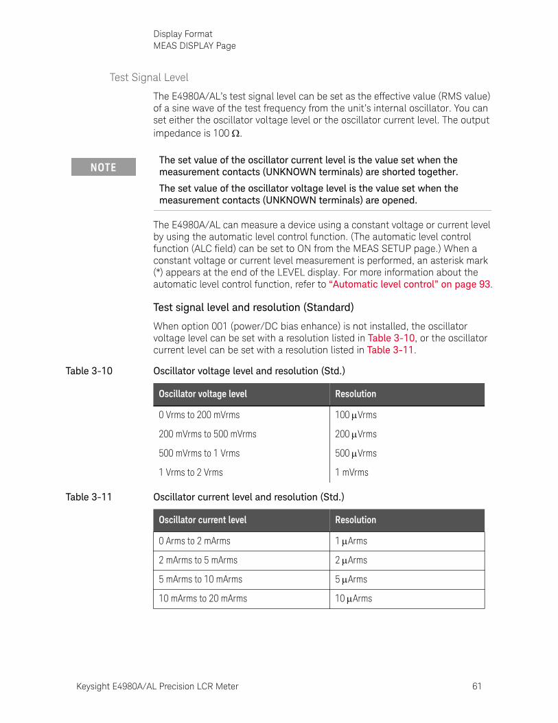
Keysight E4980A/AL Precision LCR Meter 61
Display FormatMEAS DISPLAY Page
Test Signal Level
The E4980A/AL’s test signal level can be set as the effective value (RMS value) of a sine wave of the test frequency from the unit’s internal oscillator. You can set either the oscillator voltage level or the oscillator current level. The output impedance is 100 .
The E4980A/AL can measure a device using a constant voltage or current level by using the automatic level control function. (The automatic level control function (ALC field) can be set to ON from the MEAS SETUP page.) When a constant voltage or current level measurement is performed, an asterisk mark (*) appears at the end of the LEVEL display. For more information about the automatic level control function, refer to “Automatic level control” on page 93.
Test signal level and resolution (Standard)
When option 001 (power/DC bias enhance) is not installed, the oscillator voltage level can be set with a resolution listed in Table 3-10, or the oscillator current level can be set with a resolution listed in Table 3-11.
The set value of the oscillator current level is the value set when the measurement contacts (UNKNOWN terminals) are shorted together.
The set value of the oscillator voltage level is the value set when the measurement contacts (UNKNOWN terminals) are opened.
Table 3-10 Oscillator voltage level and resolution (Std.)
Oscillator voltage level Resolution
0 Vrms to 200 mVrms 100 Vrms
200 mVrms to 500 mVrms 200 Vrms
500 mVrms to 1 Vrms 500 Vrms
1 Vrms to 2 Vrms 1 mVrms
Table 3-11 Oscillator current level and resolution (Std.)
Oscillator current level Resolution
0 Arms to 2 mArms 1 Arms
2 mArms to 5 mArms 2 Arms
5 mArms to 10 mArms 5 Arms
10 mArms to 20 mArms 10 Arms
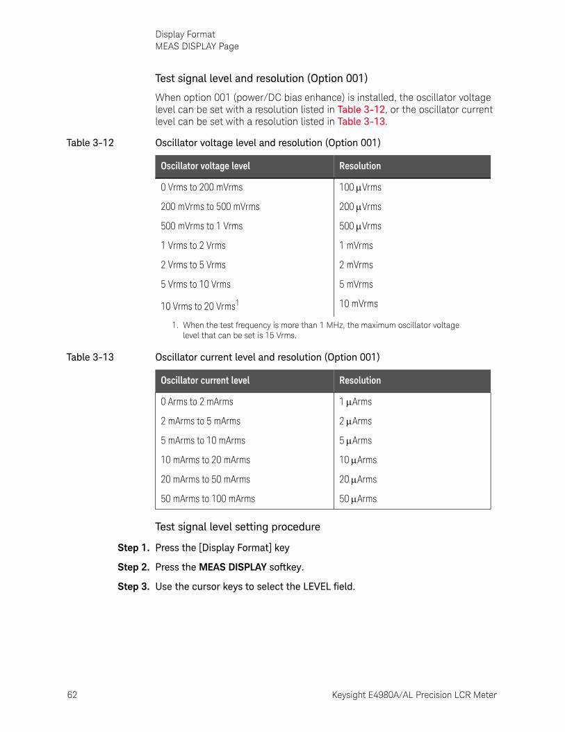
62 Keysight E4980A/AL Precision LCR Meter
Display FormatMEAS DISPLAY Page
3-
Test signal level and resolution (Option 001)
When option 001 (power/DC bias enhance) is installed, the oscillator voltage level can be set with a resolution listed in Table 3-12, or the oscillator current level can be set with a resolution listed in Table 3-13.
Test signal level setting procedure
Step 1. Press the [Display Format] key
Step 2. Press the MEAS DISPLAY softkey.
Step 3. Use the cursor keys to select the LEVEL field.
Table 3-12 Oscillator voltage level and resolution (Option 001)
Oscillator voltage level Resolution
0 Vrms to 200 mVrms 100 Vrms
200 mVrms to 500 mVrms 200 Vrms
500 mVrms to 1 Vrms 500 Vrms
1 Vrms to 2 Vrms 1 mVrms
2 Vrms to 5 Vrms 2 mVrms
5 Vrms to 10 Vrms 5 mVrms
10 Vrms to 20 Vrms1 10 mVrms
1. When the test frequency is more than 1 MHz, the maximum oscillator voltage level that can be set is 15 Vrms.
Table 3-13 Oscillator current level and resolution (Option 001)
Oscillator current level Resolution
0 Arms to 2 mArms 1 Arms
2 mArms to 5 mArms 2 Arms
5 mArms to 10 mArms 5 Arms
10 mArms to 20 mArms 10 Arms
20 mArms to 50 mArms 20 Arms
50 mArms to 100 mArms 50 Arms
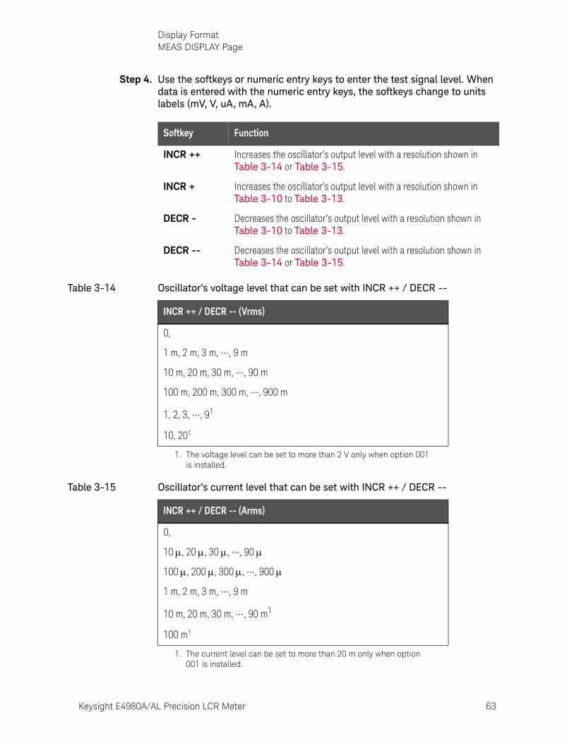
Keysight E4980A/AL Precision LCR Meter 63
Display FormatMEAS DISPLAY Page
Step 4. Use the softkeys or numeric entry keys to enter the test signal level. When data is entered with the numeric entry keys, the softkeys change to units labels (mV, V, uA, mA, A).
Softkey Function
INCR ++ Increases the oscillator’s output level with a resolution shown in Table 3-14 or Table 3-15.
INCR + Increases the oscillator’s output level with a resolution shown in Table 3-10 to Table 3-13.
DECR - Decreases the oscillator’s output level with a resolution shown in Table 3-10 to Table 3-13.
DECR -- Decreases the oscillator’s output level with a resolution shown in Table 3-14 or Table 3-15.
Table 3-14 Oscillator’s voltage level that can be set with INCR ++ / DECR --
INCR ++ / DECR -- (Vrms)
0,
1 m, 2 m, 3 m, •••, 9 m
10 m, 20 m, 30 m, •••, 90 m
100 m, 200 m, 300 m, •••, 900 m
1, 2, 3, •••, 91
1. The voltage level can be set to more than 2 V only when option 001 is installed.
10, 201
Table 3-15 Oscillator’s current level that can be set with INCR ++ / DECR --
INCR ++ / DECR -- (Arms)
0,
10 , 20 , 30 , •••, 90
100 , 200 , 300 , •••, 900
1 m, 2 m, 3 m, •••, 9 m
10 m, 20 m, 30 m, •••, 90 m1
1. The current level can be set to more than 20 m only when option 001 is installed.
100 m1
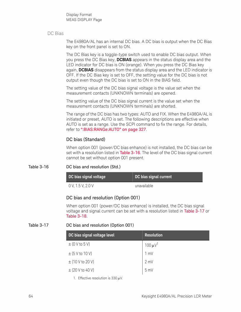
64 Keysight E4980A/AL Precision LCR Meter
Display FormatMEAS DISPLAY Page
3-
DC Bias
The E4980A/AL has an internal DC bias. A DC bias is output when the DC Bias key on the front panel is set to ON.
The DC Bias key is a toggle-type switch used to enable DC bias output. When you press the DC Bias key, DCBIAS appears in the status display area and the LED indicator for DC bias is ON (orange). When you press the DC Bias key again, DCBIAS disappears from the status display area and the LED indicator is OFF. If the DC Bias key is set to OFF, the setting value for the DC bias is not output even though the DC bias is set to ON in the BIAS field.
The setting value of the DC bias signal voltage is the value set when the measurement contacts (UNKNOWN terminals) are opened.
The setting value of the DC bias signal current is the value set when the measurement contacts (UNKNOWN terminals) are shorted.
The range of the DC bias has two types: AUTO and FIX. When the E4980A/AL is initiated or preset, AUTO is set. The following descriptions are effective when AUTO is set as a range. Use the SCPI command to fix the range. For details, refer to “:BIAS:RANGe:AUTO” on page 327.
DC bias (Standard)
When option 001 (power/DC bias enhance) is not installed, the DC bias can be set with a resolution listed in Table 3-16. The level of the DC bias signal current cannot be set without option 001 present.
DC bias and resolution (Option 001)
When option 001 (power/DC bias enhance) is installed, the DC bias signal voltage and signal current can be set with a resolution listed in Table 3-17 or Table 3-18.
Table 3-16 DC bias and resolution (Std.)
DC bias signal voltage DC bias signal current
0 V, 1.5 V, 2.0 V unavailable
Table 3-17 DC bias and resolution (Option 001)
DC bias signal voltage level Resolution
(0 V to 5 V) 100 V1
(5 V to 10 V) 1 mV
(10 V to 20 V) 2 mV
(20 V to 40 V) 5 mV
1. Effective resolution is 330 V.
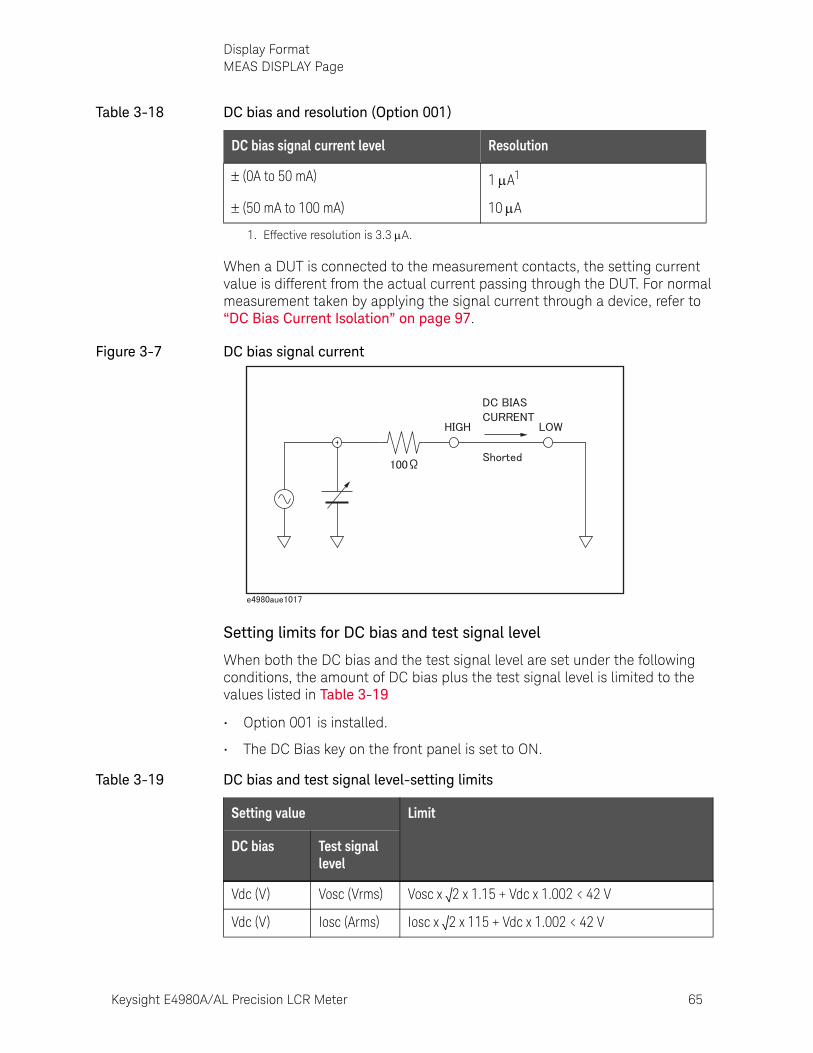
Keysight E4980A/AL Precision LCR Meter 65
Display FormatMEAS DISPLAY Page
When a DUT is connected to the measurement contacts, the setting current value is different from the actual current passing through the DUT. For normal measurement taken by applying the signal current through a device, refer to “DC Bias Current Isolation” on page 97.
Figure 3-7 DC bias signal current
Setting limits for DC bias and test signal level
When both the DC bias and the test signal level are set under the following conditions, the amount of DC bias plus the test signal level is limited to the values listed in Table 3-19
• Option 001 is installed.
• The DC Bias key on the front panel is set to ON.
Table 3-18 DC bias and resolution (Option 001)
DC bias signal current level Resolution
(0A to 50 mA) 1 A1
(50 mA to 100 mA) 10 A
1. Effective resolution is 3.3 A.
Table 3-19 DC bias and test signal level-setting limits
Setting value Limit
DC bias Test signal level
Vdc (V) Vosc (Vrms) Vosc x √2 x 1.15 + Vdc x 1.002 < 42 V
Vdc (V) Iosc (Arms) Iosc x √2 x 115 + Vdc x 1.002 < 42 V
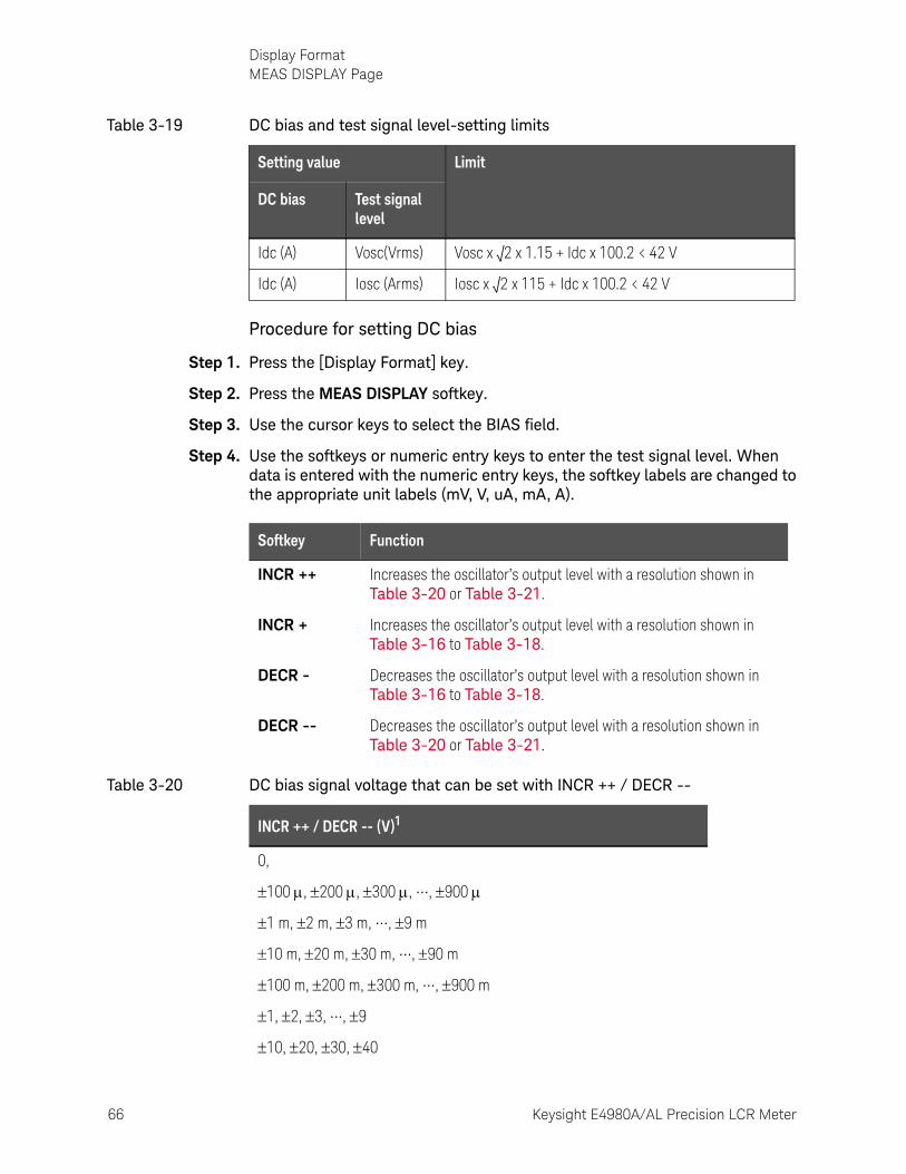
66 Keysight E4980A/AL Precision LCR Meter
Display FormatMEAS DISPLAY Page
3-
Procedure for setting DC bias
Step 1. Press the [Display Format] key.
Step 2. Press the MEAS DISPLAY softkey.
Step 3. Use the cursor keys to select the BIAS field.
Step 4. Use the softkeys or numeric entry keys to enter the test signal level. When data is entered with the numeric entry keys, the softkey labels are changed to the appropriate unit labels (mV, V, uA, mA, A).
Idc (A) Vosc(Vrms) Vosc x √2 x 1.15 + Idc x 100.2 < 42 V
Idc (A) Iosc (Arms) Iosc x √2 x 115 + Idc x 100.2 < 42 V
Table 3-19 DC bias and test signal level-setting limits
Setting value Limit
DC bias Test signal level
Softkey Function
INCR ++ Increases the oscillator’s output level with a resolution shown in Table 3-20 or Table 3-21.
INCR + Increases the oscillator’s output level with a resolution shown in Table 3-16 to Table 3-18.
DECR - Decreases the oscillator’s output level with a resolution shown in Table 3-16 to Table 3-18.
DECR -- Decreases the oscillator’s output level with a resolution shown in Table 3-20 or Table 3-21.
Table 3-20 DC bias signal voltage that can be set with INCR ++ / DECR --
INCR ++ / DECR -- (V)1
0,
100 , 200 , 300 , •••, 900
1 m, 2 m, 3 m, •••, 9 m
10 m, 20 m, 30 m, •••, 90 m
100 m, 200 m, 300 m, •••, 900 m
1, 2, 3, •••, 9
10, 20, 30, 40
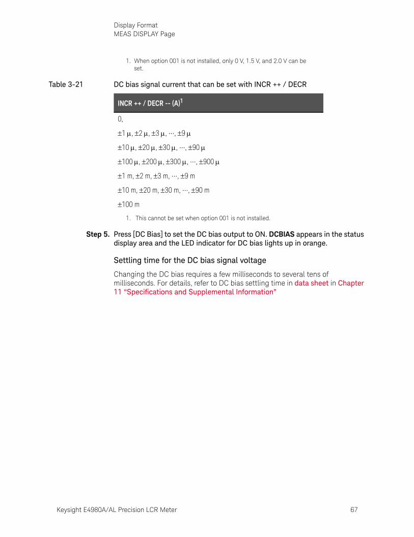
Keysight E4980A/AL Precision LCR Meter 67
Display FormatMEAS DISPLAY Page
Step 5. Press [DC Bias] to set the DC bias output to ON. DCBIAS appears in the status display area and the LED indicator for DC bias lights up in orange.
Settling time for the DC bias signal voltage
Changing the DC bias requires a few milliseconds to several tens of milliseconds. For details, refer to DC bias settling time in data sheet in Chapter 11 “Specifications and Supplemental Information”
1. When option 001 is not installed, only 0 V, 1.5 V, and 2.0 V can be set.
Table 3-21 DC bias signal current that can be set with INCR ++ / DECR
INCR ++ / DECR -- (A)1
0,
1 , 2 , 3 , •••, 9
10 , 20 , 30 , •••, 90
100 , 200 , 300 , •••, 900
1 m, 2 m, 3 m, •••, 9 m
10 m, 20 m, 30 m, •••, 90 m
100 m
1. This cannot be set when option 001 is not installed.
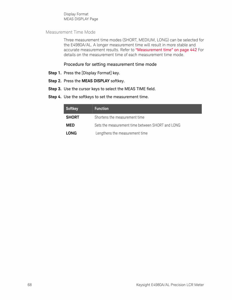
68 Keysight E4980A/AL Precision LCR Meter
Display FormatMEAS DISPLAY Page
3-
Measurement Time Mode
Three measurement time modes (SHORT, MEDIUM, LONG) can be selected for the E4980A/AL. A longer measurement time will result in more stable and accurate measurement results. Refer to “Measurement time” on page 442 For details on the measurement time of each measurement time mode.
Procedure for setting measurement time mode
Step 1. Press the [Display Format] key.
Step 2. Press the MEAS DISPLAY softkey.
Step 3. Use the cursor keys to select the MEAS TIME field.
Step 4. Use the softkeys to set the measurement time.
Softkey Function
SHORT Shortens the measurement time
MED Sets the measurement time between SHORT and LONG
LONG Lengthens the measurement time
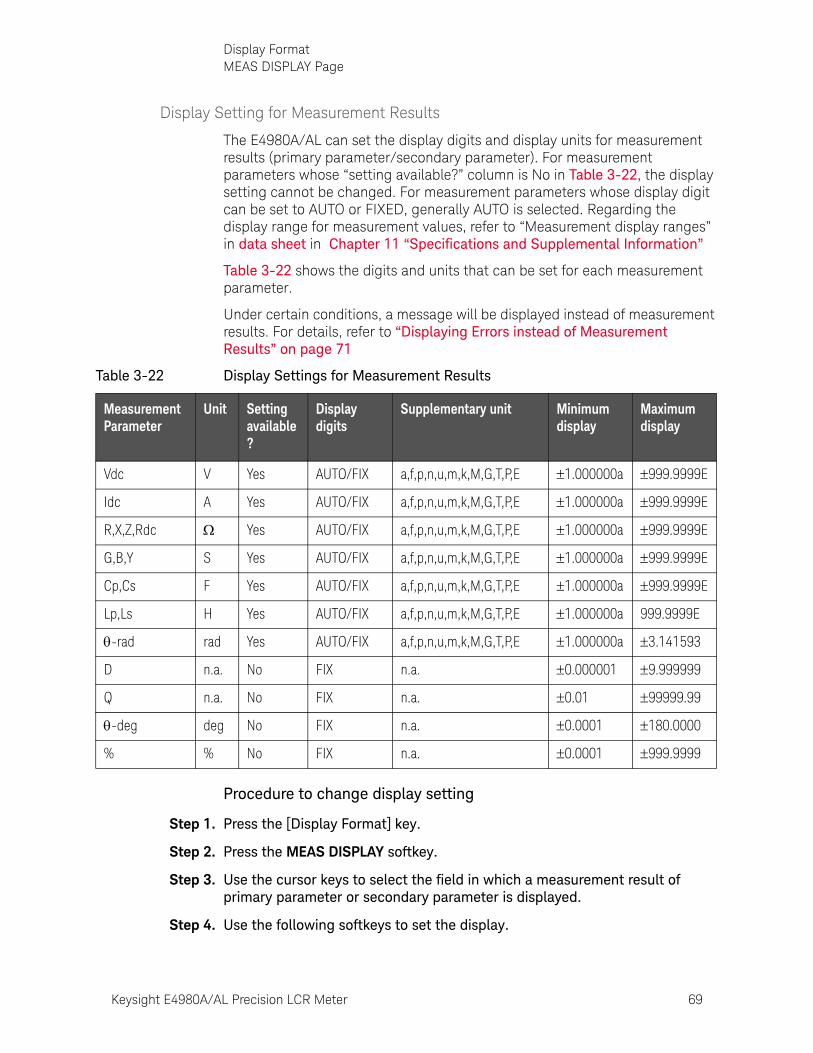
Keysight E4980A/AL Precision LCR Meter 69
Display FormatMEAS DISPLAY Page
Display Setting for Measurement Results
The E4980A/AL can set the display digits and display units for measurement results (primary parameter/secondary parameter). For measurement parameters whose “setting available?” column is No in Table 3-22, the display setting cannot be changed. For measurement parameters whose display digit can be set to AUTO or FIXED, generally AUTO is selected. Regarding the display range for measurement values, refer to “Measurement display ranges” in data sheet in Chapter 11 “Specifications and Supplemental Information”
Table 3-22 shows the digits and units that can be set for each measurement parameter.
Under certain conditions, a message will be displayed instead of measurement results. For details, refer to “Displaying Errors instead of Measurement Results” on page 71
Procedure to change display setting
Step 1. Press the [Display Format] key.
Step 2. Press the MEAS DISPLAY softkey.
Step 3. Use the cursor keys to select the field in which a measurement result of primary parameter or secondary parameter is displayed.
Step 4. Use the following softkeys to set the display.
Table 3-22 Display Settings for Measurement Results
Measurement Parameter
Unit Setting available?
Display digits
Supplementary unit Minimum display
Maximum display
Vdc V Yes AUTO/FIX a,f,p,n,u,m,k,M,G,T,P,E 1.000000a 999.9999E
Idc A Yes AUTO/FIX a,f,p,n,u,m,k,M,G,T,P,E 1.000000a 999.9999E
R,X,Z,Rdc Yes AUTO/FIX a,f,p,n,u,m,k,M,G,T,P,E 1.000000a 999.9999E
G,B,Y S Yes AUTO/FIX a,f,p,n,u,m,k,M,G,T,P,E 1.000000a 999.9999E
Cp,Cs F Yes AUTO/FIX a,f,p,n,u,m,k,M,G,T,P,E 1.000000a 999.9999E
Lp,Ls H Yes AUTO/FIX a,f,p,n,u,m,k,M,G,T,P,E 1.000000a 999.9999E
-rad rad Yes AUTO/FIX a,f,p,n,u,m,k,M,G,T,P,E 1.000000a 3.141593
D n.a. No FIX n.a. 0.000001 9.999999
Q n.a. No FIX n.a. 0.01 99999.99
-deg deg No FIX n.a. 0.0001 180.0000
% % No FIX n.a. 0.0001 999.9999

70 Keysight E4980A/AL Precision LCR Meter
Display FormatMEAS DISPLAY Page
3-
Figure 3-8 Fixed-display sample of a measurement result
Softkey Function
D.P. AUTO Automatically displays the appropriate digits and units
D.P FIX Displays measurement data using a fixed-point display format. In this case, is displayed at the fixed decimal point. (refer to Figure 3-8).
D.P POS INCR + Moves the decimal point to the left. Supplementary units are also changed.
D.P POS DECL - Moves the decimal point to the right. Supplementary units are also changed.
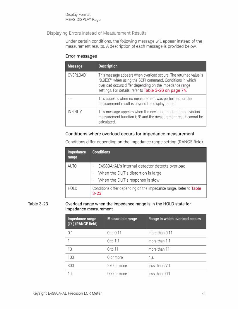
Keysight E4980A/AL Precision LCR Meter 71
Display FormatMEAS DISPLAY Page
Displaying Errors instead of Measurement Results
Under certain conditions, the following message will appear instead of the measurement results. A description of each message is provided below.
Error messages
Conditions where overload occurs for impedance measurement
Conditions differ depending on the impedance range setting (RANGE field).
Message Description
OVERLOAD This message appears when overload occurs. The returned value is “9.9E37” when using the SCPI command. Conditions in which overload occurs differ depending on the impedance range settings. For details, refer to Table 3-26 on page 74.
--- This appears when no measurement was performed, or the measurement result is beyond the display range.
INFINITY This message appears when the deviation mode of the deviation measurement function is % and the measurement result cannot be calculated.
Impedance range
Conditions
AUTO • E4980A/AL’s internal detector detects overload
• When the DUT’s distortion is large
• When the DUT’s response is slow
HOLD Conditions differ depending on the impedance range. Refer to Table 3-23
Table 3-23 Overload range when the impedance range is in the HOLD state for impedance measurement
Impedance range ( ) (RANGE field)
Measurable range Range in which overload occurs
0.1 0 to 0.11 more than 0.11
1 0 to 1.1 more than 1.1
10 0 to 11 more than 11
100 0 or more n.a.
300 270 or more less than 270
1 k 900 or more less than 900
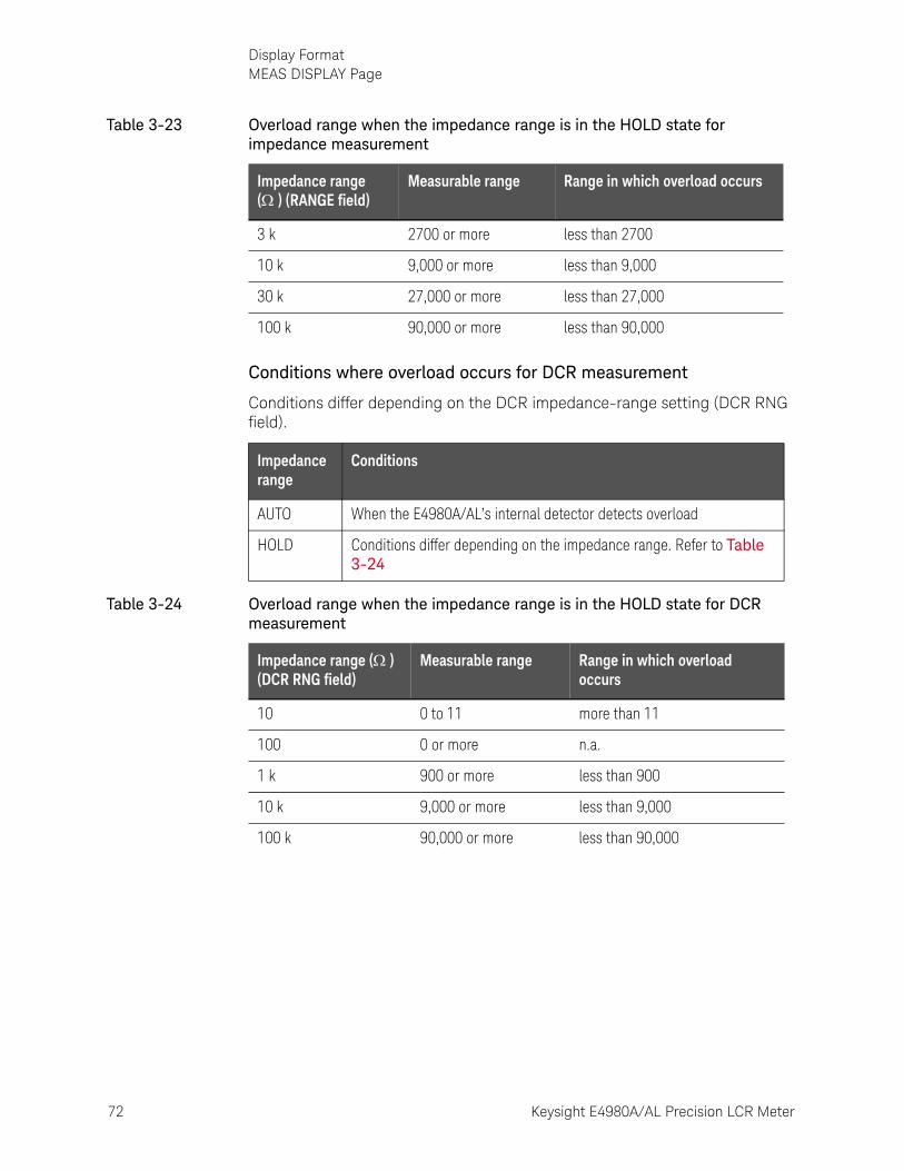
72 Keysight E4980A/AL Precision LCR Meter
Display FormatMEAS DISPLAY Page
3-
Conditions where overload occurs for DCR measurement
Conditions differ depending on the DCR impedance-range setting (DCR RNG field).
3 k 2700 or more less than 2700
10 k 9,000 or more less than 9,000
30 k 27,000 or more less than 27,000
100 k 90,000 or more less than 90,000
Table 3-23 Overload range when the impedance range is in the HOLD state for impedance measurement
Impedance range ( ) (RANGE field)
Measurable range Range in which overload occurs
Impedance range
Conditions
AUTO When the E4980A/AL’s internal detector detects overload
HOLD Conditions differ depending on the impedance range. Refer to Table 3-24
Table 3-24 Overload range when the impedance range is in the HOLD state for DCR measurement
Impedance range ( ) (DCR RNG field)
Measurable range Range in which overload occurs
10 0 to 11 more than 11
100 0 or more n.a.
1 k 900 or more less than 900
10 k 9,000 or more less than 9,000
100 k 90,000 or more less than 90,000
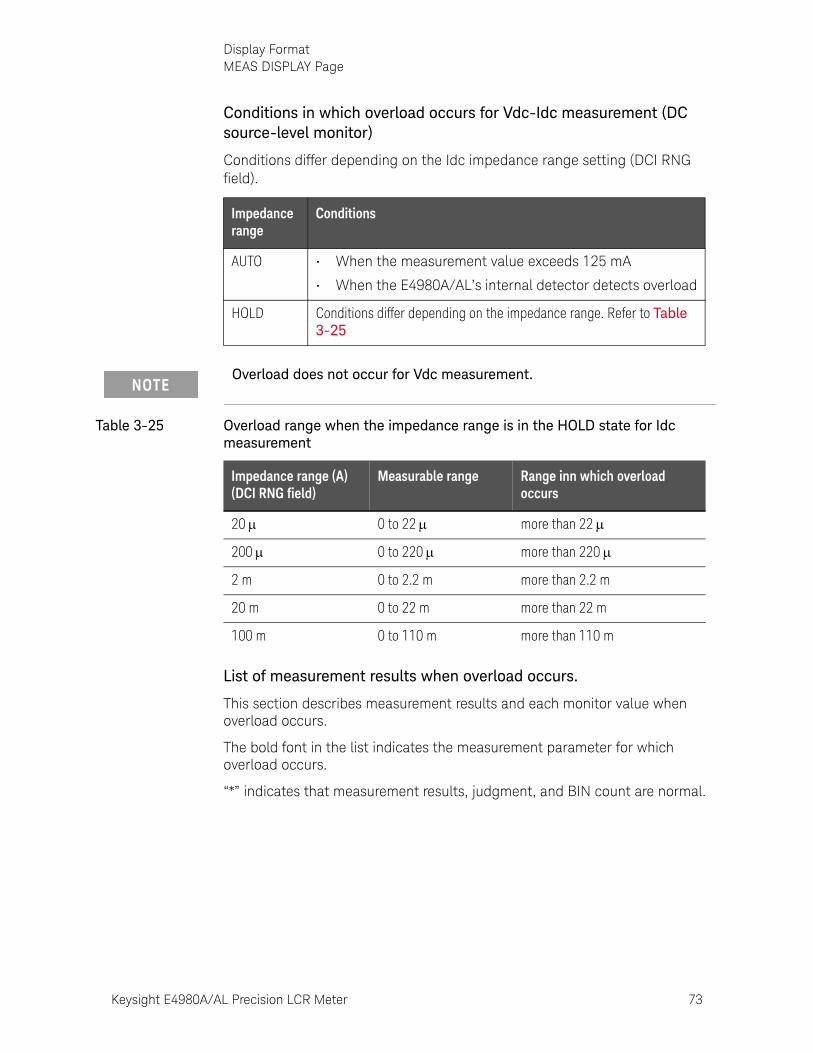
Keysight E4980A/AL Precision LCR Meter 73
Display FormatMEAS DISPLAY Page
Conditions in which overload occurs for Vdc-Idc measurement (DC source-level monitor)
Conditions differ depending on the Idc impedance range setting (DCI RNG field).
List of measurement results when overload occurs.
This section describes measurement results and each monitor value when overload occurs.
The bold font in the list indicates the measurement parameter for which overload occurs.
“*” indicates that measurement results, judgment, and BIN count are normal.
Impedance range
Conditions
AUTO • When the measurement value exceeds 125 mA
• When the E4980A/AL’s internal detector detects overload
HOLD Conditions differ depending on the impedance range. Refer to Table 3-25
Overload does not occur for Vdc measurement.
Table 3-25 Overload range when the impedance range is in the HOLD state for Idc measurement
Impedance range (A) (DCI RNG field)
Measurable range Range inn which overload occurs
20 0 to 22 more than 22
200 0 to 220 more than 220
2 m 0 to 2.2 m more than 2.2 m
20 m 0 to 22 m more than 22 m
100 m 0 to 110 m more than 110 m

74 Keysight E4980A/AL Precision LCR Meter
Display FormatMEAS DISPLAY Page
3-
Table 3-26 List of measurement results when overload occurs
Measurement parameter
Meas. value (primary)
Meas. value (secondary)
VAC/IACmonitor
VDCmonitor
IDC monitor
IN/OUT
BIN No.
Impedance measurement (except for Ls/Lp-Rdc)
OVLD OVLD --- --- --- L OUT
Impedance measurement (except for Ls/Lp-Rdc)
OVLD OVLD --- --- --- L OUT
Impedance measurement (Ls/Lp-Rdc)
OVLD --- --- --- --- L OUT
DCR measurement (Ls/Lp-Rdc)
* OVLD * * * L OUT
Vdc-Idc measurement * OVLD 0 * OVLD L OUT
Other than Vdc-Idc measurement
* * * OVLD --- * *
Other than Vdc-Idc measurement
* * * * OVLD * *
OVLD is displayed as OVERLOAD on the display.

Keysight E4980A/AL Precision LCR Meter 75
Display FormatMEAS DISPLAY Page
Monitor Information
The following describes monitor information displayed on the MEAS DISPLAY page. This information cannot be changed on the MEAS DISPLAY page.
Monitor information
Description
VAC Displays the test signal voltage level (AC voltage). Displays measurement results regardless of the type of measurement parameter
IAC Displays the test signal current level (AC current). Displays measurement results regardless of the type of measurement parameter
VDC Displays the DC bias voltage level (DC voltage). Set the VDC MON field of the [Means Setup] page to ON when you want to display it.1
IDC Displays the DC bias current level (DC current). Set the IDC MON field of the [Means Setup] page to ON when you want to display it
CORR Displays the correction information of enabled correction types (OPEN/SHORT/LOAD) and cable length
CH Displays the channel number in the multi-correction mode2
1. This can be displayed only when option 001 is installed.2. SINGLE is displayed when option 301 is not installed.
The VDC/IDC monitor values are the ones measured under the condition that the setting value of the test signal level (LEVEL field) is output. Therefore, these values are different from the measurement results displayed when the measurement parameter is DC voltage measurement/DC current measurement (Vdc-Idc).
76 Keysight E4980A/AL Precision LCR Meter
Display FormatBIN NO. DISPLAY Page
3-
BIN NO. DISPLAY PageWhen you press the [Display Format] key and BIN No. soft key, the BIN No. DISPLAY page appears. The bin sorting results are displayed in large characters while the measurement results are shown in normal characters. The following measurement controls can be set from the BIN No. DISPLAY page (The field in parenthesis is used when this control is set).
• Comparator function ON/OFF (COMP field)
This page also provides the following information in the monitor areas (each monitor area looks like a field but is not). These conditions can be set from the MEAS SETUP page and the CORRECTION page, and most conditions can be set from the MEAS DISPLAY page.
• Measurement Function (FUNC)
• Impedance range (RANGE)
• Test Frequency (FREQ)
• Test Signal Level (LEVEL)
• DC Bias (BIAS)
• Measurement Time Mode (MEAS TIME)
• Correction Information (CORR)
Figure 3-9 shows the available fields and the softkeys that correspond to each field on this page.
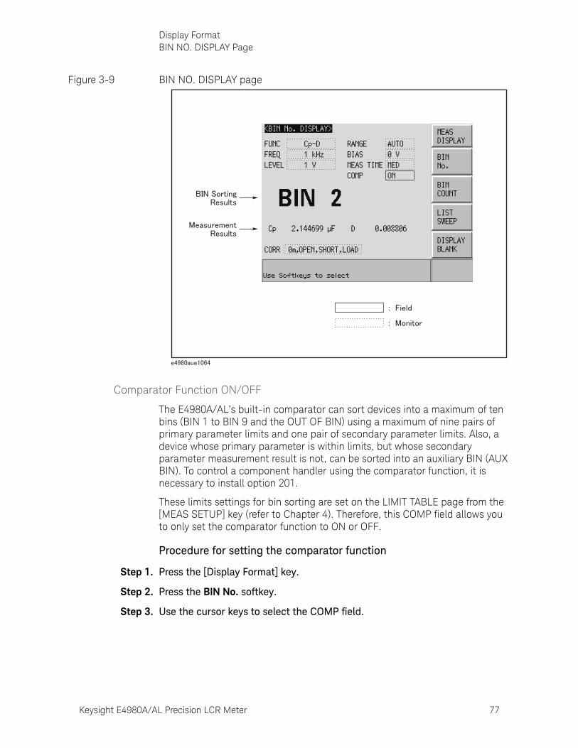
Keysight E4980A/AL Precision LCR Meter 77
Display FormatBIN NO. DISPLAY Page
Figure 3-9 BIN NO. DISPLAY page
Comparator Function ON/OFF
The E4980A/AL’s built-in comparator can sort devices into a maximum of ten bins (BIN 1 to BIN 9 and the OUT OF BIN) using a maximum of nine pairs of primary parameter limits and one pair of secondary parameter limits. Also, a device whose primary parameter is within limits, but whose secondary parameter measurement result is not, can be sorted into an auxiliary BIN (AUX BIN). To control a component handler using the comparator function, it is necessary to install option 201.
These limits settings for bin sorting are set on the LIMIT TABLE page from the [MEAS SETUP] key (refer to Chapter 4). Therefore, this COMP field allows you to only set the comparator function to ON or OFF.
Procedure for setting the comparator function
Step 1. Press the [Display Format] key.
Step 2. Press the BIN No. softkey.
Step 3. Use the cursor keys to select the COMP field.

78 Keysight E4980A/AL Precision LCR Meter
Display FormatBIN NO. DISPLAY Page
3-
Step 4. Use the softkeys to set the comparator function to ON or OFF.
Softkey Function
ON Sets the comparator to ON
OFF Sets the comparator to OFF
Keysight E4980A/AL Precision LCR Meter 79
Display FormatBIN COUNT DISPLAY Page
BIN COUNT DISPLAY PageWhen you press the [Display Format] key and BIN COUNT softkey, the BIN COUNT DISPLAY page is displayed. On this page, the comparator’s count results are displayed (The field in parentheses is used for setting).
• Counter function ON/OFF (COUNT field)
This page also provides the following information in the monitor areas (each monitor area looks like a field, but is not). These conditions can be set from the LIMIT TABLE SETUP page. For more details, refer to “LIMIT TABLE SETUP Page” on page 134.
• Measurement Function (FUNC)
• Nominal Value (NOM)
• Test Frequency (FREQ)
• Bin Sorting Low/High Limits (LOW/HIGH)
• BIN Sorting Results (RESULT)
Figure 3-10 shows the available fields and the softkeys that correspond to each field on this page.
You can set it so that a beep sounds when the sorting result is output. For details, refer to “Beep Feature” on page 143.
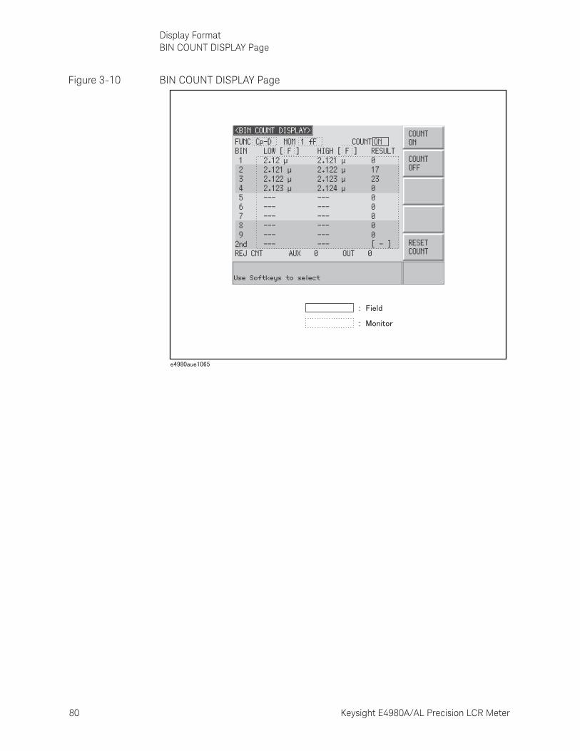
80 Keysight E4980A/AL Precision LCR Meter
Display FormatBIN COUNT DISPLAY Page
3-
Figure 3-10 BIN COUNT DISPLAY Page
Keysight E4980A/AL Precision LCR Meter 81
Display FormatBIN COUNT DISPLAY Page
Counter Function
The E4980A/AL is capable of counting bins. The number of devices sorted into each bin is counted while the unit sorts the devices into appropriate bins using the comparator function.
The maximum count is 999,999. The counting operation stops and the overflow message “----” appears when this value is reached.
Counter setting procedure
Step 1. Press the [Display Format] key.
Step 2. Press the BIN COUNT softkey.
Step 3. Use the cursor keys to select the COUNT field.
Step 4. Use the softkeys to set the counter to ON/OFF.
Counter reset procedure
Step 1. Press the [Display Format] key.
Step 2. Press the BIN COUNT softkey.
Step 3. Use the cursor keys to select the COUNT field.
Step 4. Use the softkeys to press RESET COUNT.
Softkey Function
COUNT ON Sets the counter to ON
COUNT OFF Sets the counter to OFF
The counter is reset when the instrument setting state is recalled.
82 Keysight E4980A/AL Precision LCR Meter
Display FormatLIST SWEEP DISPLAY Page
3-
LIST SWEEP DISPLAY PageWhen you press the [Display Format] key and LIST SWEEP softkey, the LIST SWEEP DISPLAY page appears. On this page in is possible to enter sweep points and measurement limits of up to 201 frequencies, test signal levels, DC bias, or DC source. The sweep points are automatically swept and the measurement results are compared to the limits.
On the LIST SWEEP DISPLAY page, the sweep points are swept and the measurement results are compared to the limits. During a sweep, an asterisk mark (*) will appear on the left side of the sweep point currently being measured. The following measurement controls can be set from this page (Each field in parentheses is used for setting).
• Sweep Mode of the List Sweep Measurement (MODE)
• Confirmation for Each Page of the List Sweep Measurement (No. of fields)
The sweep point list cannot be set from this page; it can only be set from the LIST SWEEP SETUP page.
Figure 3-11 shows the available fields and the softkeys that correspond to each field on this page.
You can set it so that a beep sounds when the sorting result is output. For details, refer to “Beep Feature” on page 143.

Keysight E4980A/AL Precision LCR Meter 83
Display FormatLIST SWEEP DISPLAY Page
Figure 3-11 LIST SWEEP DISPLAY Page
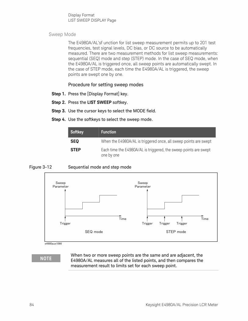
84 Keysight E4980A/AL Precision LCR Meter
Display FormatLIST SWEEP DISPLAY Page
3-
Sweep Mode
The E4980A/AL’sf unction for list sweep measurement permits up to 201 test frequencies, test signal levels, DC bias, or DC source to be automatically measured. There are two measurement methods for list sweep measurements: sequential (SEQ) mode and step (STEP) mode. In the case of SEQ mode, when the E4980A/AL is triggered once, all sweep points are automatically swept. In the case of STEP mode, each time the E4980A/AL is triggered, the sweep points are swept one by one.
Procedure for setting sweep modes
Step 1. Press the [Display Format] key.
Step 2. Press the LIST SWEEP softkey.
Step 3. Use the cursor keys to select the MODE field.
Step 4. Use the softkeys to select the sweep mode.
Figure 3-12 Sequential mode and step mode
Softkey Function
SEQ When the E4980A/AL is triggered once, all sweep points are swept
STEP Each time the E4980A/AL is triggered, the sweep points are swept one by one
When two or more sweep points are the same and are adjacent, the E4980A/AL measures all of the listed points, and then compares the measurement result to limits set for each sweep point.
Keysight E4980A/AL Precision LCR Meter 85
Display FormatLIST SWEEP DISPLAY Page
Procedure to confirm the sweep points
Step 1. Press the [Display Format] key.
Step 2. Press the LIST SWEEP softkey.
Step 3. Use the cursor keys to select the No. of fields.
Step 4. Use the softkeys to confirm the sweep points on each page.
Softkey Function
PREV PAGE Displays the previous page
NEXT PAGE Displays the next page
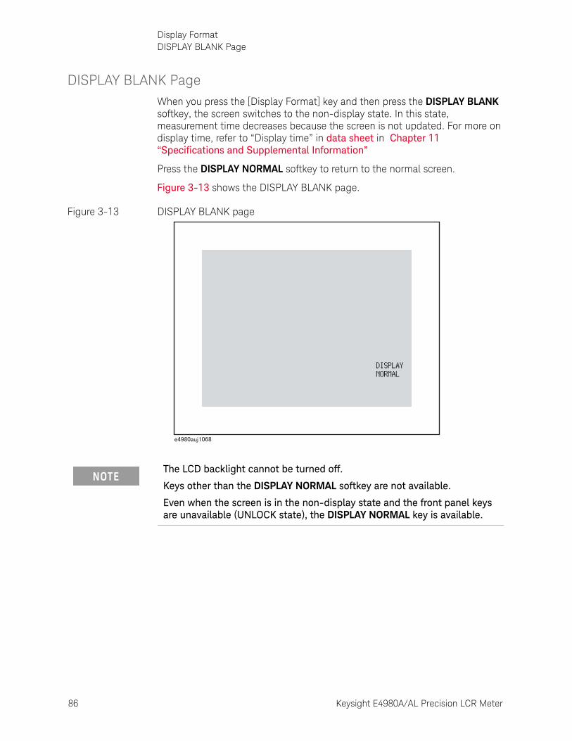
86 Keysight E4980A/AL Precision LCR Meter
Display FormatDISPLAY BLANK Page
3-
DISPLAY BLANK PageWhen you press the [Display Format] key and then press the DISPLAY BLANK softkey, the screen switches to the non-display state. In this state, measurement time decreases because the screen is not updated. For more on display time, refer to “Display time” in data sheet in Chapter 11 “Specifications and Supplemental Information”
Press the DISPLAY NORMAL softkey to return to the normal screen.
Figure 3-13 shows the DISPLAY BLANK page.
Figure 3-13 DISPLAY BLANK page
The LCD backlight cannot be turned off.
Keys other than the DISPLAY NORMAL softkey are not available.
Even when the screen is in the non-display state and the front panel keys are unavailable (UNLOCK state), the DISPLAY NORMAL key is available.
87
Keysight E4980A/AL Precision LCR Meter
User’s Guide
4 Configuring Measurement Conditions (Display and Function Related Settings)
This chapter provides information on the various settings accessible through the MEAS SETUP page of the E4980A/AL.
Initializing the InstrumentThe E4980A/AL can be initialized into one of the following four default states:
For more information on each default state and affected settings, see Appendix C , “List of Default Values,” on page 449.
Table 4-1 Three default states of E4980A/AL and how it is initialized
Default state How the instrument is initialized
CLEAR SETTING When you initialize the instrument into this state, all basic parameters configurable through the front panel and SCPI commands are cleared. (You get the same result by issuing the *RST command).
CLEAR SET&CORR When you initialize the instrument into this state, calibration data and backup items listed in the initial setting list are all cleared. 1(You can gain the same result by issuing the :SYST:PRES command).
FACTORY DEFAULT When you initialize the instrument into this state, it reverts to factory default settings with all user-configurable data cleared.
LAN RESET When you initialize the instrument into this state, the LAN setting is returned to the factory default state.
1. It takes a few seconds for the initialization to complete.
88 Keysight E4980A/AL Precision LCR Meter
Configuring Measurement Conditions (Display and Function Related Settings)MEAS SETUP page
4-
MEAS SETUP pageYou can press the [Meas Setup] key to open the MEAS SETUP page. In the MEAS SETUP page, you can configure each of the following measurement controls with the cursor placed in the corresponding field (denoted in parentheses).
• Comment line (USER COMMENT field)
• Measurement function (FUNC field)
• Measurement range (RANGE field)
• Measurement frequency (FREQ field)
• DC bias (BIAS field)
• Measurement signal level (LEVEL field)
• Measurement time mode (MEAS TIME field)
• Trigger mode (TRIG field)
• averaging factor (AVG field)
• Automatic level control (ALC field)
• Signal voltage level monitor ON/OFF (VDC MON field)
• DC resistance range (DCR RNG field)
• Signal current level monitor ON/OFF (IDC MON field)
• Bias current isolation (DCI ISO field)
• Trigger delay time (TRIG DLY field)
• DC current (DCI) range (DCI RNG field)
• Step delay time (STEP DLY field)
• DC source (DC SRC field)
• Automatic bias polarity control (BIAS POL)
• Deviation measurement mode A (DEV A field)
• Reference value for deviation measurement mode A (REF A field)
• Deviation measurement mode B (DEV B field)
• Reference value for deviation measurement mode B (REF B field)
The following fields are accessible through both the MEAS SETUP and MEAS DISPLAY pages:
• Measurement function (FUNC field)
• Measurement range (RANGE field)
• Measurement frequency (FREQ field)
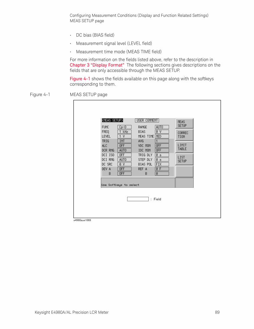
Keysight E4980A/AL Precision LCR Meter 89
Configuring Measurement Conditions (Display and Function Related Settings)MEAS SETUP page
• DC bias (BIAS field)
• Measurement signal level (LEVEL field)
• Measurement time mode (MEAS TIME field)
For more information on the fields listed above, refer to the description in Chapter 3 “Display Format” The following sections gives descriptions on the fields that are only accessible through the MEAS SETUP.
Figure 4-1 shows the fields available on this page along with the softkeys corresponding to them.
Figure 4-1 MEAS SETUP page
90 Keysight E4980A/AL Precision LCR Meter
Configuring Measurement Conditions (Display and Function Related Settings)MEAS SETUP page
4-
Comment line
You can enter a comment in the comment line by using the softkeys to enter letters and the entry keys to enter numbers from 0 through 9, +, -, and period (.). Your entered comment is saved in the internal memory or external USB memory along with the control settings of the E4980A/AL. When you load the control settings, your saved comment is loaded as well.
The comment can be up to 30 characters in length. However, only the first 22 characters are displayed in the area.
Until you enter a comment into the comment line, the default text “USER COMMENT” appears in the comment line.
To enter a comment into the comment line:
Step 1. Press [Meas Setup].
Step 2. Press the MEAS SETUP softkey.
Step 3. Using the cursor keys, select the USER COMMENT field.
Step 4. To input a letter, use the following softkeys to cycle through letters in alphabetical order and then select your desired letter:
Step 5. Press the ADD CHAR softkey.Your selected single character appears in the input line area.
Step 6. Repeat Step 4 and Step 5 to input subsequent characters.
Step 7. Press the ENTER softkey to enter your text in the USER COMMENT field.
You can also use the DISPlay:LINE command to enter ASCII characters into the comment line.
If there is already a comment, select that comment (field).
Softkey Description
NEXT Displays the next letter to the letter currently displayed in the ADD CHAR softkey.
PREV Displays the previous letter to the letter currently displayed in the ADD CHAR softkey.
To input a number, use the entry keys.
Keysight E4980A/AL Precision LCR Meter 91
Configuring Measurement Conditions (Display and Function Related Settings)MEAS SETUP page
Trigger mode
Functional Description
The E4980A/AL supports four trigger modes: INT (internal), EXT (external), MAN (manual), and BUS (GPIB bus).
For more on the E4980A/AL’s trigger system, see “Trigger System” on page 249 in Chapter 8 “Overview of Remote Control”
Trigger mode Description
INT After you bring up the display page using the [Display Format] key, the instrument continuously repeats the measurement cycle.
MAN After you bring up the display page using the [Display Format] key, the instrument performs one cycle of measurement each time you press the [Trigger] key.
EXT After you bring up the display page using the [Display Format] key, the instrument performs one cycle of measurement each time a rising TTL pulse is input to the external trigger input terminal on the rear panel. In the EXT (external trigger) mode, you can also trigger the instrument by short-circuiting the core wire of the external trigger input terminal and the instrument’s ground line (the core wire is connected to a circuit that contains a pull-up resistor). Figure 4-2 shows the TTL pulse specifications.
Also, you can trigger the instrument from the handler interface or scanner interface.
BUS The E4980A/AL performs one cycle of measurement each time it receives a trigger command sent via GPIB/USB/LAN.
E4980A/AL ignores any trigger that is input during a measurement cycle. Be sure to trigger the instrument when it is not in a measurement cycle.
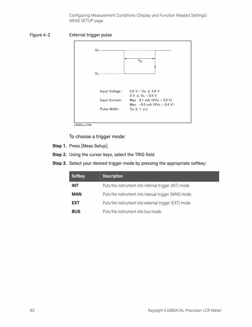
92 Keysight E4980A/AL Precision LCR Meter
Configuring Measurement Conditions (Display and Function Related Settings)MEAS SETUP page
4-
Figure 4-2 External trigger pulse
To choose a trigger mode:
Step 1. Press [Meas Setup].
Step 2. Using the cursor keys, select the TRIG field.
Step 3. Select your desired trigger mode by pressing the appropriate softkey:
Softkey Description
INT Puts the instrument into internal trigger (INT) mode.
MAN Puts the instrument into manual trigger (MAN) mode.
EXT Puts the instrument into external trigger (EXT) mode.
BUS Puts the instrument into bus mode.
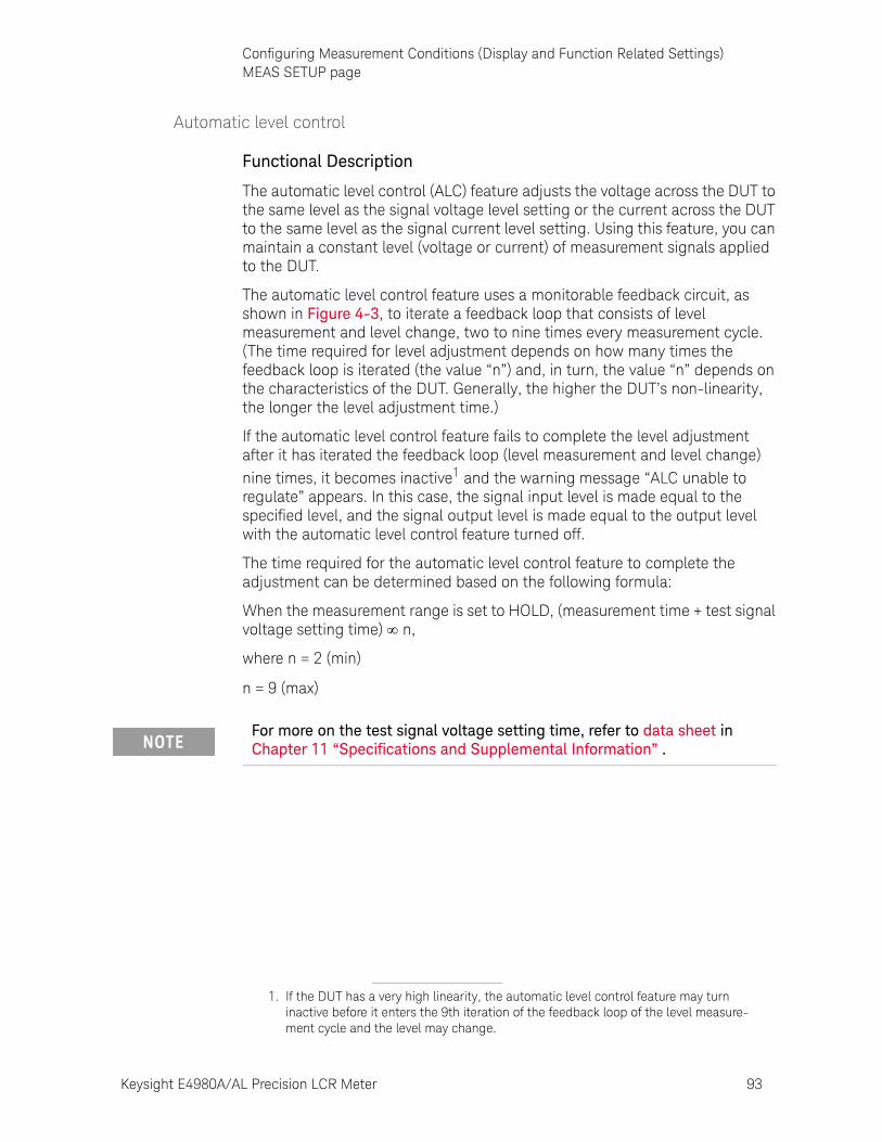
Keysight E4980A/AL Precision LCR Meter 93
Configuring Measurement Conditions (Display and Function Related Settings)MEAS SETUP page
Automatic level control
Functional Description
The automatic level control (ALC) feature adjusts the voltage across the DUT to the same level as the signal voltage level setting or the current across the DUT to the same level as the signal current level setting. Using this feature, you can maintain a constant level (voltage or current) of measurement signals applied to the DUT.
The automatic level control feature uses a monitorable feedback circuit, as shown in Figure 4-3, to iterate a feedback loop that consists of level measurement and level change, two to nine times every measurement cycle. (The time required for level adjustment depends on how many times the feedback loop is iterated (the value “n”) and, in turn, the value “n” depends on the characteristics of the DUT. Generally, the higher the DUT’s non-linearity, the longer the level adjustment time.)
If the automatic level control feature fails to complete the level adjustment after it has iterated the feedback loop (level measurement and level change) nine times, it becomes inactive1 and the warning message “ALC unable to regulate” appears. In this case, the signal input level is made equal to the specified level, and the signal output level is made equal to the output level with the automatic level control feature turned off.
The time required for the automatic level control feature to complete the adjustment can be determined based on the following formula:
When the measurement range is set to HOLD, (measurement time + test signal voltage setting time) n,
where n = 2 (min)
n = 9 (max)
1. If the DUT has a very high linearity, the automatic level control feature may turn inactive before it enters the 9th iteration of the feedback loop of the level measure-ment cycle and the level may change.
For more on the test signal voltage setting time, refer to data sheet in Chapter 11 “Specifications and Supplemental Information” .
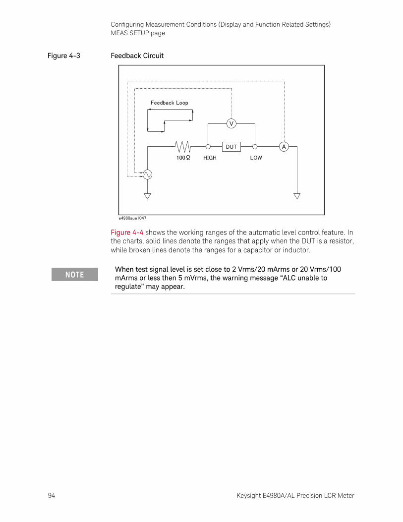
94 Keysight E4980A/AL Precision LCR Meter
Configuring Measurement Conditions (Display and Function Related Settings)MEAS SETUP page
4-
Figure 4-3 Feedback Circuit
Figure 4-4 shows the working ranges of the automatic level control feature. In the charts, solid lines denote the ranges that apply when the DUT is a resistor, while broken lines denote the ranges for a capacitor or inductor.
When test signal level is set close to 2 Vrms/20 mArms or 20 Vrms/100 mArms or less then 5 mVrms, the warning message “ALC unable to regulate” may appear.
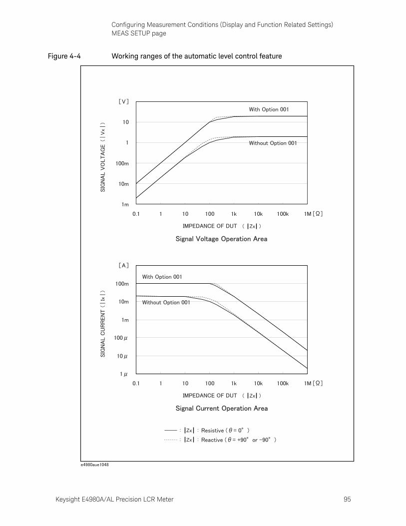
Keysight E4980A/AL Precision LCR Meter 95
Configuring Measurement Conditions (Display and Function Related Settings)MEAS SETUP page
Figure 4-4 Working ranges of the automatic level control feature
96 Keysight E4980A/AL Precision LCR Meter
Configuring Measurement Conditions (Display and Function Related Settings)MEAS SETUP page
4-
To set up the automatic level control feature:
Step 1. Press [Meas Setup].
Step 2. Using the cursor keys, select the ALC field.
Step 3. Use the following softkeys:
Softkey Description
ON Turns ON the automatic level control feature.
OFF Turns OFF the automatic level control feature.
Keysight E4980A/AL Precision LCR Meter 97
Configuring Measurement Conditions (Display and Function Related Settings)MEAS SETUP page
DC Bias Current Isolation
Functional Description
When the instrument is equipped with Option 001 (Power/DC Bias Enhance), it supports DC bias settings up to 40V. The DC bias current actually applied to the DUT can be checked using the IDC monitor.
The DC bias current isolation feature is intended to prevent DC current from affecting the measurement circuit. To turn on/off this feature, use the DCI ISO field.
For information on the maximum DC bias current with the DC bias current isolation feature ON or OFF, see “Maximum DC bias current” in data sheet in Chapter 11 “Specifications and Supplemental Information” .
When the DC bias current isolation feature is OFF and the DC bias current applied to the DUT exceeds the maximum level, turn this feature ON. If a DC bias current exceeding the maximum level is applied to the DUT, the instrument will fail to return correct measurements.
To set up the DC bias current isolation feature:
Step 1. Press [Meas Setup].
Step 2. Using the cursor keys, select the DCI ISO field.
Step 3. Use the following softkeys:
Step 4. Set the DCI measurement range. For more information, see “To set the DCI range:” on page 106.
The DC bias current isolation feature affects measurement accuracy. For more information, see “Relative measurement accuracy with bias current isolation” in data sheet in Chapter 11 “Specifications and Supplemental Information” .
Softkey Description
ON Turn ON the DC bias current isolation feature.
OFF Turn OFF the DC bias current isolation feature.

98 Keysight E4980A/AL Precision LCR Meter
Configuring Measurement Conditions (Display and Function Related Settings)MEAS SETUP page
4-
Averaging Factor
Functional Description
The averaging feature of the E4980A/AL allows you to obtain moving average values of successive measurement results.
You can specify the averaging factor within the range of 1 to 256 in steps of 1.
To set up the averaging factor:
Step 1. Press [Meas Setup].
Step 2. Using the cursor keys, select the AVG field.
Step 3. Enter the averaging factor using the softkeys or entry keys. If you have used the entry keys to enter the value, the softkey labels change to unit labels (x1).
The averaging feature does not affect the measurement results of the DC bias voltage monitor and DC bias current monitor even when a particular averaging factor is specified.
Softkey Description
INCR ++ Increments the averaging factor in steps of 1, 2, 4, 8, 16, 32, 64, 128, and 256.
INCR + Increments the averaging factor in steps of 1.
DECR - Decrements the averaging factor in steps of 1.
DECR -- Decrements the averaging factor in steps of 1, 2, 4, 8, 16, 32, 64, 128, and 256.
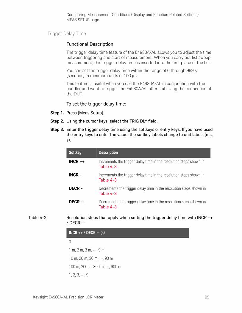
Keysight E4980A/AL Precision LCR Meter 99
Configuring Measurement Conditions (Display and Function Related Settings)MEAS SETUP page
Trigger Delay Time
Functional Description
The trigger delay time feature of the E4980A/AL allows you to adjust the time between triggering and start of measurement. When you carry out list sweep measurement, this trigger delay time is inserted into the first place of the list.
You can set the trigger delay time within the range of 0 through 999 s (seconds) in minimum units of 100 s.
This feature is useful when you use the E4980A/AL in conjunction with the handler and want to trigger the E4980A/AL after stabilizing the connection of the DUT.
To set the trigger delay time:
Step 1. Press [Meas Setup].
Step 2. Using the cursor keys, select the TRIG DLY field.
Step 3. Enter the trigger delay time using the softkeys or entry keys. If you have used the entry keys to enter the value, the softkey labels change to unit labels (ms, s).
Softkey Description
INCR ++ Increments the trigger delay time in the resolution steps shown in Table 4-3.
INCR + Increments the trigger delay time in the resolution steps shown in Table 4-3.
DECR - Decrements the trigger delay time in the resolution steps shown in Table 4-3.
DECR -- Decrements the trigger delay time in the resolution steps shown in Table 4-3.
Table 4-2 Resolution steps that apply when setting the trigger delay time with INCR ++ / DECR --
INCR ++ / DECR -- (s)
0
1 m, 2 m, 3 m, •••, 9 m
10 m, 20 m, 30 m, •••, 90 m
100 m, 200 m, 300 m, •••, 900 m
1, 2, 3, •••, 9
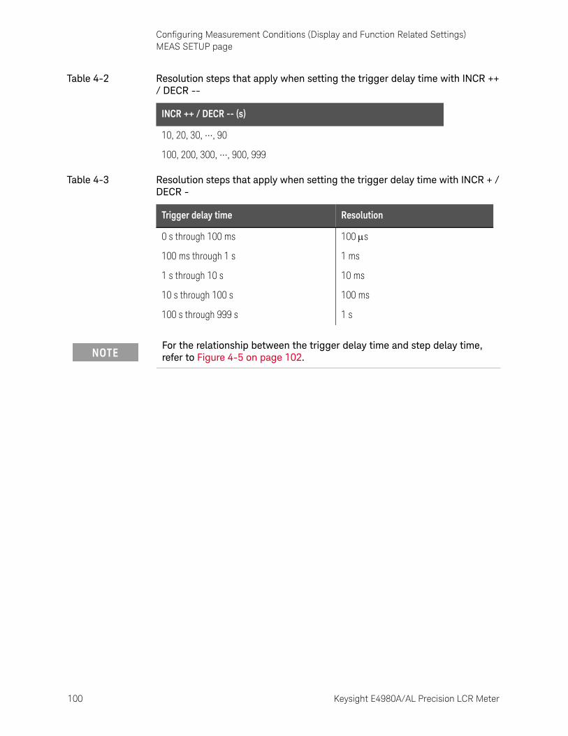
100 Keysight E4980A/AL Precision LCR Meter
Configuring Measurement Conditions (Display and Function Related Settings)MEAS SETUP page
4-
10, 20, 30, •••, 90
100, 200, 300, •••, 900, 999
Table 4-3 Resolution steps that apply when setting the trigger delay time with INCR + / DECR -
Trigger delay time Resolution
0 s through 100 ms 100 s
100 ms through 1 s 1 ms
1 s through 10 s 10 ms
10 s through 100 s 100 ms
100 s through 999 s 1 s
For the relationship between the trigger delay time and step delay time, refer to Figure 4-5 on page 102.
Table 4-2 Resolution steps that apply when setting the trigger delay time with INCR ++ / DECR --
INCR ++ / DECR -- (s)
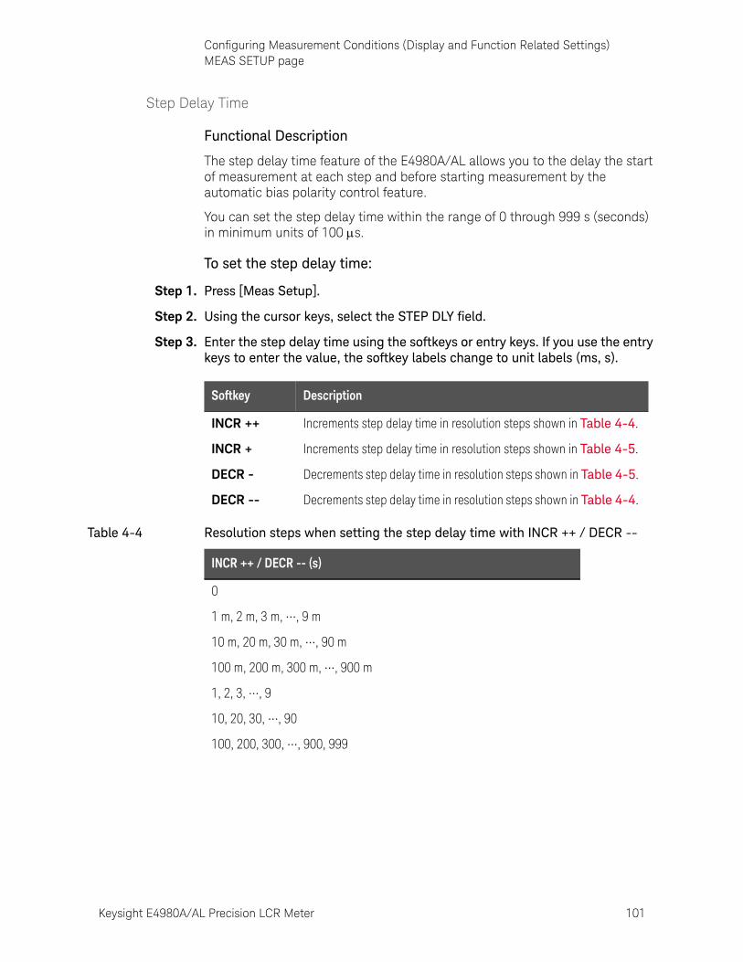
Keysight E4980A/AL Precision LCR Meter 101
Configuring Measurement Conditions (Display and Function Related Settings)MEAS SETUP page
Step Delay Time
Functional Description
The step delay time feature of the E4980A/AL allows you to the delay the start of measurement at each step and before starting measurement by the automatic bias polarity control feature.
You can set the step delay time within the range of 0 through 999 s (seconds) in minimum units of 100 s.
To set the step delay time:
Step 1. Press [Meas Setup].
Step 2. Using the cursor keys, select the STEP DLY field.
Step 3. Enter the step delay time using the softkeys or entry keys. If you use the entry keys to enter the value, the softkey labels change to unit labels (ms, s).
Softkey Description
INCR ++ Increments step delay time in resolution steps shown in Table 4-4.
INCR + Increments step delay time in resolution steps shown in Table 4-5.
DECR - Decrements step delay time in resolution steps shown in Table 4-5.
DECR -- Decrements step delay time in resolution steps shown in Table 4-4.
Table 4-4 Resolution steps when setting the step delay time with INCR ++ / DECR --
INCR ++ / DECR -- (s)
0
1 m, 2 m, 3 m, •••, 9 m
10 m, 20 m, 30 m, •••, 90 m
100 m, 200 m, 300 m, •••, 900 m
1, 2, 3, •••, 9
10, 20, 30, •••, 90
100, 200, 300, •••, 900, 999
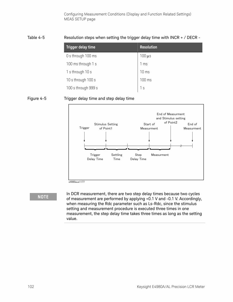
102 Keysight E4980A/AL Precision LCR Meter
Configuring Measurement Conditions (Display and Function Related Settings)MEAS SETUP page
4-
Figure 4-5 Trigger delay time and step delay time
Table 4-5 Resolution steps when setting the trigger delay time with INCR + / DECR -
Trigger delay time Resolution
0 s through 100 ms 100 s
100 ms through 1 s 1 ms
1 s through 10 s 10 ms
10 s through 100 s 100 ms
100 s through 999 s 1 s
In DCR measurement, there are two step delay times because two cycles of measurement are performed by applying +0.1 V and -0.1 V. Accordingly, when measuring the Rdc parameter such as Ls-Rdc, since the stimulus setting and measurement procedure is executed three times in one measurement, the step delay time takes three times as long as the setting value.
Keysight E4980A/AL Precision LCR Meter 103
Configuring Measurement Conditions (Display and Function Related Settings)MEAS SETUP page
DC Bias Voltage Monitor
Functional Description
The DC bias voltage monitor feature allows you to monitor the actual level of the signal voltage across the DUT. The DC bias voltage monitor value is only displayed in the VDC monitor area of the MEAS DISPLAY page.
To set up the signal voltage level monitor feature:
Step 1. Press [Meas Setup].
Step 2. Using the cursor keys, select the VDC MON field.
Step 3. Use the following softkeys:
Softkey Description
ON Turn ON the DC bias voltage monitor feature.
OFF Turn OFF the DC bias voltage monitor feature.

104 Keysight E4980A/AL Precision LCR Meter
Configuring Measurement Conditions (Display and Function Related Settings)MEAS SETUP page
4-
DC Bias Current Monitor
Functional Description
The DC bias current monitor feature allows you to monitor the actual level of the signal current across the DUT. The DC bias current monitor value is only displayed in the IDC monitor area of the MEAS DISPLAY page.
To set up the signal voltage level monitor feature:
Step 1. Press [Meas Setup].
Step 2. Using the cursor keys, select the IDC MON field.
Step 3. Use the following softkeys:
Softkey Description
ON Turn ON the DC bias current monitor feature.
OFF Turn OFF the DC bias current monitor feature.
Keysight E4980A/AL Precision LCR Meter 105
Configuring Measurement Conditions (Display and Function Related Settings)MEAS SETUP page
DCR Range
Functional Description
In DCR measurement, the E4980A/AL’s internal signal level is set to 0 V, and then two cycles of measurement are performed by applying +0.1 V and -0.1 V.
You can set the range for DCR measurement. DCR range can be set to one of five hold ranges, which are available when the measurement parameters are Lp-Rdc and Ls-Rdc.
To set the DCR range:
Step 1. Press [Meas Setup].
Step 2. Press the MEAS SETUP softkey.
Step 3. Using the cursor keys, select the DCR RNG field.
Step 4. Enter the DCR range using the softkeys or entry keys. If you use the entry keys to enter the value, the softkey labels change to unit labels (, k).
Model Measurement range ()
Standard 10, 100, 1 k, 10 k, 100 k
When you set the DCR range to HOLD, DCI range and measurement range are also automatically set to HOLD; when you set the DCR range to AUTO, DCI range and measurement range are also automatically set to AUTO.
If you start DCR measurement with DC bias ON, DC bias is automatically turned OFF. When the measurement parameters are Lp-Rdc and Ls-Rdc, DC bias cannot be set to ON. An error message appears if you try to do this.
Softkey Description
AUTO Sets the DCR range to AUTO.
HOLD Sets the DCR range to HOLD (manual).
INCR + Use this softkey to increment the measurement range. The DCR range changes to HOLD.
DECR - Use this softkey to decrement the measurement range. The DCR range changes to HOLD.
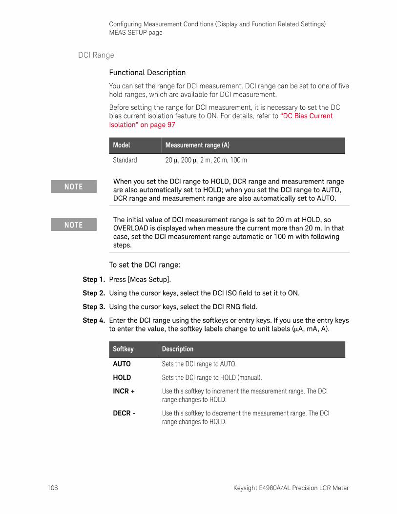
106 Keysight E4980A/AL Precision LCR Meter
Configuring Measurement Conditions (Display and Function Related Settings)MEAS SETUP page
4-
DCI Range
Functional Description
You can set the range for DCI measurement. DCI range can be set to one of five hold ranges, which are available for DCI measurement.
Before setting the range for DCI measurement, it is necessary to set the DC bias current isolation feature to ON. For details, refer to “DC Bias Current Isolation” on page 97
To set the DCI range:
Step 1. Press [Meas Setup].
Step 2. Using the cursor keys, select the DCI ISO field to set it to ON.
Step 3. Using the cursor keys, select the DCI RNG field.
Step 4. Enter the DCI range using the softkeys or entry keys. If you use the entry keys to enter the value, the softkey labels change to unit labels (A, mA, A).
Model Measurement range (A)
Standard 20 , 200 , 2 m, 20 m, 100 m
When you set the DCI range to HOLD, DCR range and measurement range are also automatically set to HOLD; when you set the DCI range to AUTO, DCR range and measurement range are also automatically set to AUTO.
The initial value of DCI measurement range is set to 20 m at HOLD, so OVERLOAD is displayed when measure the current more than 20 m. In that case, set the DCI measurement range automatic or 100 m with following steps.
Softkey Description
AUTO Sets the DCI range to AUTO.
HOLD Sets the DCI range to HOLD (manual).
INCR + Use this softkey to increment the measurement range. The DCI range changes to HOLD.
DECR - Use this softkey to decrement the measurement range. The DCI range changes to HOLD.
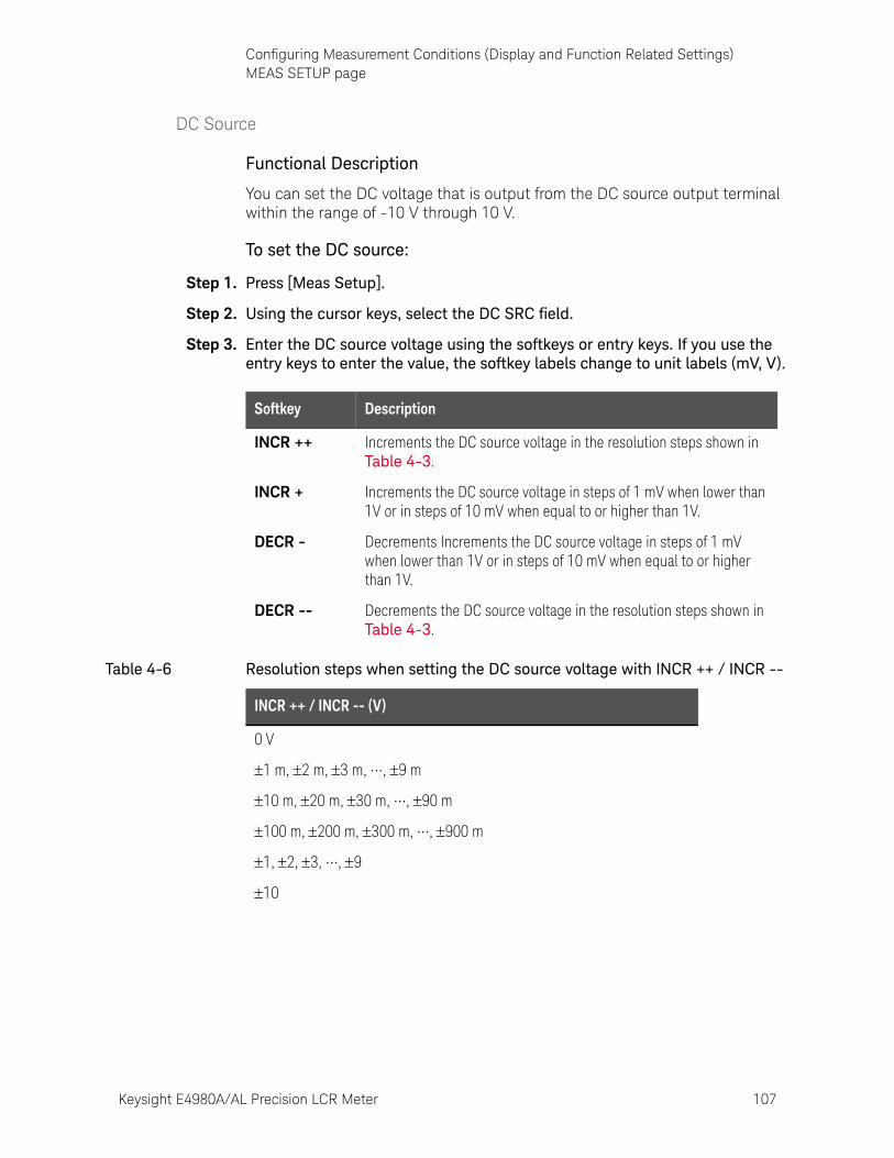
Keysight E4980A/AL Precision LCR Meter 107
Configuring Measurement Conditions (Display and Function Related Settings)MEAS SETUP page
DC Source
Functional Description
You can set the DC voltage that is output from the DC source output terminal within the range of -10 V through 10 V.
To set the DC source:
Step 1. Press [Meas Setup].
Step 2. Using the cursor keys, select the DC SRC field.
Step 3. Enter the DC source voltage using the softkeys or entry keys. If you use the entry keys to enter the value, the softkey labels change to unit labels (mV, V).
Softkey Description
INCR ++ Increments the DC source voltage in the resolution steps shown in Table 4-3.
INCR + Increments the DC source voltage in steps of 1 mV when lower than 1V or in steps of 10 mV when equal to or higher than 1V.
DECR - Decrements Increments the DC source voltage in steps of 1 mV when lower than 1V or in steps of 10 mV when equal to or higher than 1V.
DECR -- Decrements the DC source voltage in the resolution steps shown in Table 4-3.
Table 4-6 Resolution steps when setting the DC source voltage with INCR ++ / INCR --
INCR ++ / INCR -- (V)
0 V
1 m, 2 m, 3 m, •••, 9 m
10 m, 20 m, 30 m, •••, 90 m
100 m, 200 m, 300 m, •••, 900 m
1, 2, 3, •••, 9
10
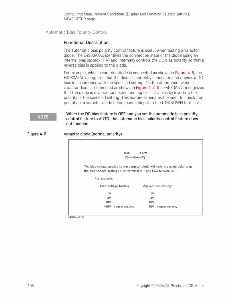
108 Keysight E4980A/AL Precision LCR Meter
Configuring Measurement Conditions (Display and Function Related Settings)MEAS SETUP page
4-
Automatic Bias Polarity Control
Functional Description
The automatic bias polarity control feature is useful when testing a varactor diode. The E4980A/AL identifies the connection state of the diode using an internal bias (approx. 1 V) and internally controls the DC bias polarity so that a reverse bias is applied to the diode.
For example, when a varactor diode is connected as shown in Figure 4-6, the E4980A/AL recognizes that the diode is correctly connected and applies a DC bias in accordance with the specified setting. On the other hand, when a varactor diode is connected as shown in Figure 4-7, the E4980A/AL recognizes that the diode is reverse-connected and applies a DC bias by inverting the polarity of the specified setting. This feature eliminates the need to check the polarity of a varactor diode before connecting it to the UNKNOWN terminal.
Figure 4-6 Varactor diode (normal polarity)
When the DC bias feature is OFF and you set the automatic bias polarity control feature to AUTO, the automatic bias polarity control feature does not function.
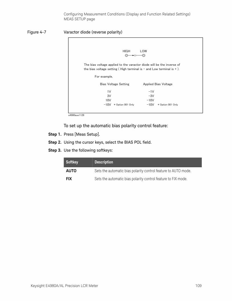
Keysight E4980A/AL Precision LCR Meter 109
Configuring Measurement Conditions (Display and Function Related Settings)MEAS SETUP page
Figure 4-7 Varactor diode (reverse polarity)
To set up the automatic bias polarity control feature:
Step 1. Press [Meas Setup].
Step 2. Using the cursor keys, select the BIAS POL field.
Step 3. Use the following softkeys:
Softkey Description
AUTO Sets the automatic bias polarity control feature to AUTO mode.
FIX Sets the automatic bias polarity control feature to FIX mode.
110 Keysight E4980A/AL Precision LCR Meter
Configuring Measurement Conditions (Display and Function Related Settings)MEAS SETUP page
4-
Deviation Measurement
Functional Description
The deviation measurement feature allows you to display deviation values instead of actual measurements. A deviation is expressed as the difference between the actual measurement and the stored reference value. The deviation measurement feature is useful when you observe how a particular value of a device/component changes under varying conditions of temperature, frequency, bias, and other influences.
You can apply the deviation measurement feature to the primary or secondary parameter or both. The deviation measurement feature supports the following two modes:
• ABS (absolute value) deviation measurement
Identifies and displays the difference between the actual measurement of the DUT and the stored reference value. This value is calculated based on the following formula:
• % (percentage) deviation measurement
Identifies the difference between the actual measurement of the DUT and the stored reference value and displays it as a percentage of the reference value. This percentage deviation value is calculated based on the following formula:
To set up the deviation measurement feature:
Step 1. Press [Meas Setup].
Step 2. Using the cursor keys, select the REF A field.
ABS = X-Y
X actual measurement of the DUT
Y stored reference value
% = (X-Y)/Y100 (%)
X actual measurement of the DUT
Y stored reference value
Keysight E4980A/AL Precision LCR Meter 111
Configuring Measurement Conditions (Display and Function Related Settings)MEAS SETUP page
Step 3. Enter the reference value using the softkeys or entry keys. If you use the entry keys to enter the value, the softkey labels change to unit labels (n, u, m, x1, k). 1
Step 4. Using the cursor keys, select the DEV A field.
Step 5. Select the deviation mode for the primary parameter by pressing the appropriate softkey:
Step 6. Using the cursor keys, select the (DEV) B field.
Step 7. Select the deviation mode for the primary parameter using the softkeys described in Step 5.
Softkey Description
MEASURE If you want to use a particular device/component as the reference, connect the DUT and press this key. Then the instrument measures the DUT once and automatically fills the REF A and (REF) B fields with the measured values, which now serve as the reference values.
1. If the primary parameter of the measurement function is C, the softkey labels show these units: p, n, u, m, x1.
Softkey Description
ABS Displays the deviation as the difference from the reference value.
% Displays the deviation as a percentage of the reference value.
OFF Turns OFF deviation measurement.
112 Keysight E4980A/AL Precision LCR Meter
Configuring Measurement Conditions (Display and Function Related Settings)CORRECTION page
4-
CORRECTION pagePressing the [Meas Setup] key followed by the CORRECTION opens the CORRECTION page. The CORRECTION page allows you to perform Open/Short/Load correction to compensate for any error caused by disturbances such as stray admittances and residual impedances. It also allows you to select the cable length.
The correction feature supports the following two correction methods:
• Correction based on all frequency points
• Correction based on user-specified frequency points
Correction based on all frequency points involves performing open/short correction at all measurement points throughout the entire frequency range.
Correction based on user-specified frequency points involves performing open/short/load correction at the user-specified frequency points.
Each correction dataset can be deleted by using the [Preset] key. For more information, see “Initializing the Instrument” on page 87.
In this page, you can configure each of the following controls with the cursor placed in the corresponding field (denoted in parentheses).
• Open correction (OPEN field)
• Short correction (SHORT field)
• Load correction (LOAD field)
• Cable length selection (CABLE field)
• Multiple/single correction mode selection (MODE field)
• Measurement function for load correction (FUNC field)
• Channel selection for multiple correction mode (CH field)
• User-specified frequencies 1 to 201 for open/load/short correction (SPOT and FREQ fields)
• Measurement value and reference value at specified frequency points for open/short/load correction (REF A, REF B, OPEN A, OPEN B, SHORT A, SHORT B, LOAD A, and LOAD B fields)
Figure 4-8 shows the fields available on this page along with the softkeys corresponding to them.
Correction when measuring DC resistance is performed only when the measurement parameter is Lp-Rdc and Ls-Rdc.
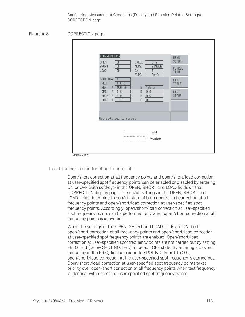
Keysight E4980A/AL Precision LCR Meter 113
Configuring Measurement Conditions (Display and Function Related Settings)CORRECTION page
Figure 4-8 CORRECTION page
To set the correction function to on or off
Open/short correction at all frequency points and open/short/load correction at user-specified spot frequency points can be enabled or disabled by entering ON or OFF (with softkeys) in the OPEN, SHORT and LOAD fields on the CORRECTION display page. The on/off settings in the OPEN, SHORT and LOAD fields determine the on/off state of both open/short correction at all frequency points and open/short/load correction at user-specified spot frequency points. Accordingly, open/short/load correction at user-specified spot frequency points can be performed only when open/short correction at all frequency points is activated.
When the settings of the OPEN, SHORT and LOAD fields are ON, both open/short correction at all frequency points and open/short/load correction at user-specified spot frequency points are enabled. Open/short/load correction at user-specified spot frequency points are not carried out by setting FREQ field (below SPOT NO. field) to default OFF state. By entering a desired frequency in the FREQ field allocated to SPOT NO. from 1 to 201, open/short/load correction at the user-specified spot frequency is carried out. Open/short /load correction at user-specified spot frequency points takes priority over open/short correction at all frequency points when test frequency is identical with one of the user-specified spot frequency points.
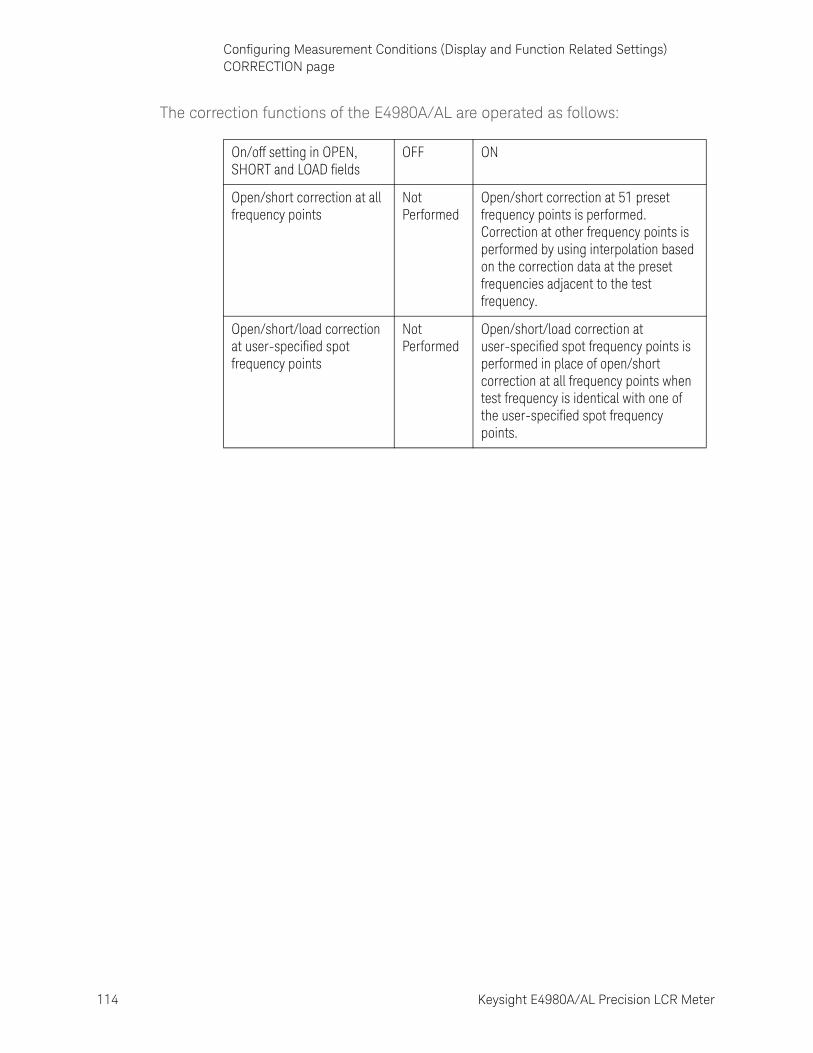
114 Keysight E4980A/AL Precision LCR Meter
Configuring Measurement Conditions (Display and Function Related Settings)CORRECTION page
4-
The correction functions of the E4980A/AL are operated as follows:
On/off setting in OPEN, SHORT and LOAD fields
OFF ON
Open/short correction at all frequency points
Not Performed
Open/short correction at 51 preset frequency points is performed. Correction at other frequency points is performed by using interpolation based on the correction data at the preset frequencies adjacent to the test frequency.
Open/short/load correction at user-specified spot frequency points
Not Performed
Open/short/load correction at user-specified spot frequency points is performed in place of open/short correction at all frequency points when test frequency is identical with one of the user-specified spot frequency points.

Keysight E4980A/AL Precision LCR Meter 115
Configuring Measurement Conditions (Display and Function Related Settings)CORRECTION page
Open Correction
The open correction feature of the E4980A/AL compensates for any stray admittances (G, B) that may exist within the interval from the calibration plane, which is determined by the selected cable length, to the DUT connecting points (see Figure 4-9).
Figure 4-9 Stray admittances
Description of Correction Based on All Frequency Points
In this correction method, open correction data are collected from all 51 predetermined frequency points, regardless of the test frequency settings. At the other frequency points, correction is done using data calculated by interpolating the data collected at the 51 points (see Figure 4-10). The following tables list the 51 predetermined frequency points:
Table 4-7 Predetermined frequency points in correction based on all frequency points
Test frequency points
20 Hz 100 Hz 1 kHz 10 kHz 100 kHz 1 MHz
25 Hz 120 Hz 1.2 kHz 12 kHz 120 kHz 1.2 MHz
30 Hz 150 Hz 1.5 kHz 15 kHz 150 kHz 1.5 MHz
40 Hz 200 Hz 2 kHz 20 kHz 200 kHz 2 MHz
50 Hz 250 Hz 2.5 kHz 25 kHz 250 kHz
60 Hz 300 Hz 3 kHz 30 kHz 300 kHz
80 Hz 400 Hz 4 kHz 40 kHz 400 kHz
500 Hz 5 kHz 50 kHz 500 kHz
600 Hz 6 kHz 60 kHz 600 kHz
800 Hz 8 kHz 80 kHz 800 kHz
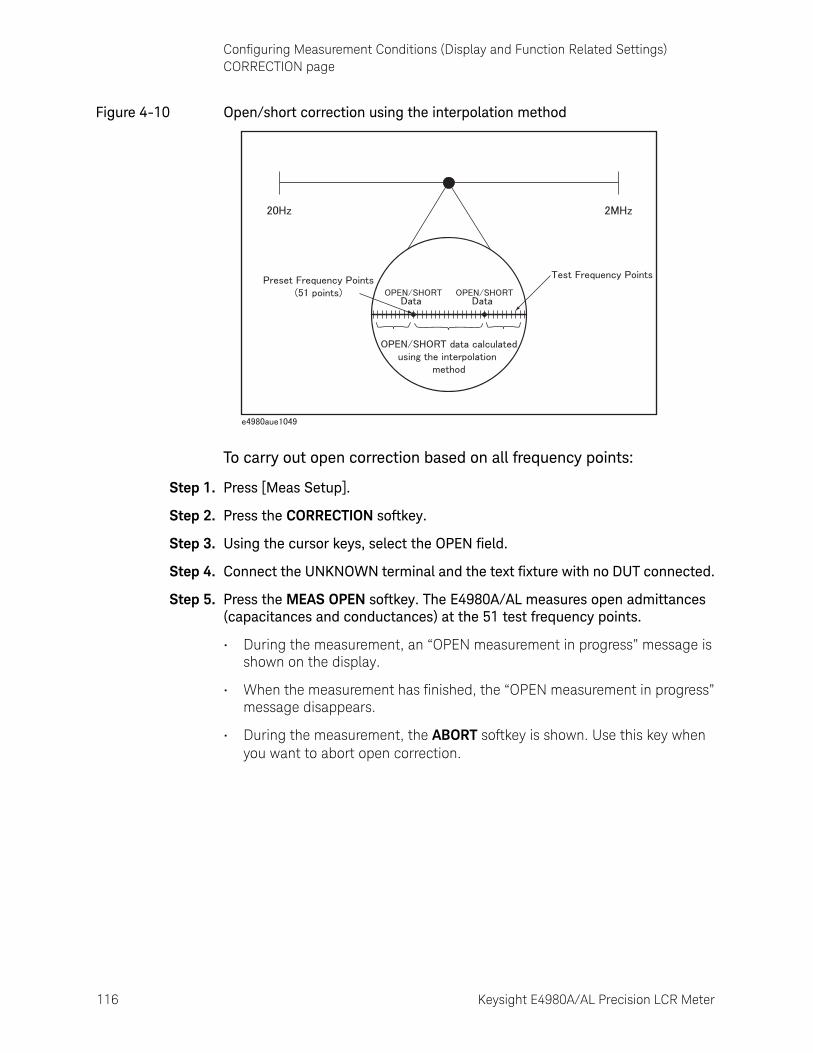
116 Keysight E4980A/AL Precision LCR Meter
Configuring Measurement Conditions (Display and Function Related Settings)CORRECTION page
4-
Figure 4-10 Open/short correction using the interpolation method
To carry out open correction based on all frequency points:
Step 1. Press [Meas Setup].
Step 2. Press the CORRECTION softkey.
Step 3. Using the cursor keys, select the OPEN field.
Step 4. Connect the UNKNOWN terminal and the text fixture with no DUT connected.
Step 5. Press the MEAS OPEN softkey. The E4980A/AL measures open admittances (capacitances and conductances) at the 51 test frequency points.
• During the measurement, an “OPEN measurement in progress” message is shown on the display.
• When the measurement has finished, the “OPEN measurement in progress” message disappears.
• During the measurement, the ABORT softkey is shown. Use this key when you want to abort open correction.
Keysight E4980A/AL Precision LCR Meter 117
Configuring Measurement Conditions (Display and Function Related Settings)CORRECTION page
The E4980A/AL do not have a functionality to check whether the OPEN correction data is valid or not. Any OPEN correction data can be set, even if work-related mistakes are made in measuring for the OPEN correction.
For example,
- improper OPEN is used.
- setting up the OPEN state and SHORT state inversely.
- the OPEN is connected incompletely.
- fixture or cable is connected incompletely.
- previous correction data is used.
- after correction, different length cable/different fixture is connected or settings of frequency/level is changed.
If OPEN correction data is invalid, it may cause inappropriate measurements without showing warning message. Be careful about the connection of appropriate OPEN state. You cannot check the measured values for the OPEN correction.
If "E43 Measurement failed" error is displayed during the OPEN correction, measure the OPEN state (disable OPEN correction[OPEN OFF]) at some frequencies (100, 1k, 1MHz etc.) and check if the following conditions happen. If one of them happens, try its suggestion.
"ALC unable to regulate" warning message is displayed (suggestion: turn off ALC)
"Signal source overload" warning message is displayed (suggestion: reduce test signal)
"Overload" is displayed (Measurement result becomes overload) (suggestion: check cabling/fixturing)
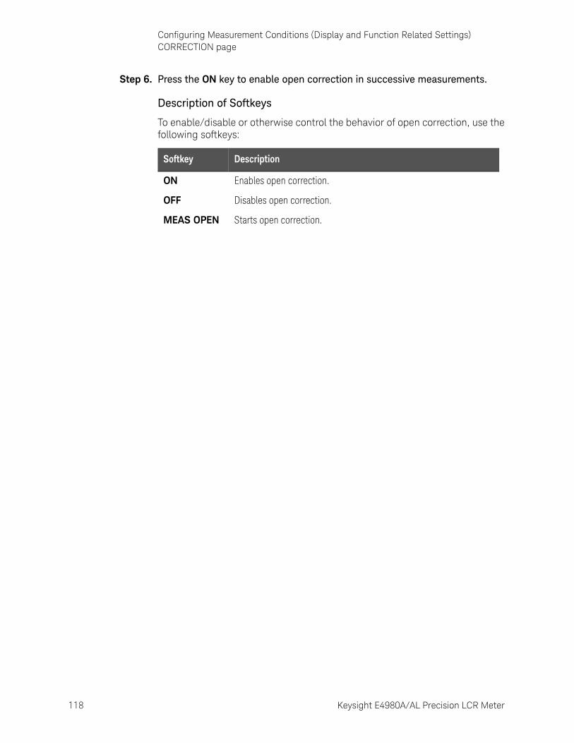
118 Keysight E4980A/AL Precision LCR Meter
Configuring Measurement Conditions (Display and Function Related Settings)CORRECTION page
4-
Step 6. Press the ON key to enable open correction in successive measurements.
Description of Softkeys
To enable/disable or otherwise control the behavior of open correction, use the following softkeys:
Softkey Description
ON Enables open correction.
OFF Disables open correction.
MEAS OPEN Starts open correction.
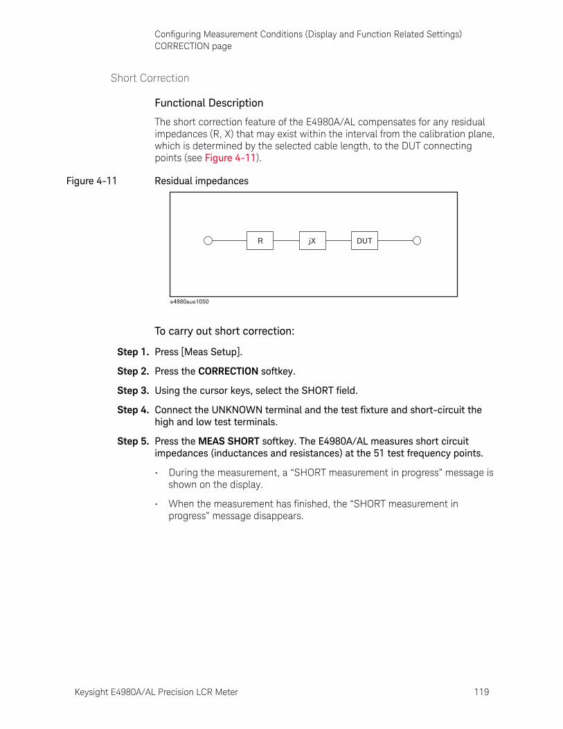
Keysight E4980A/AL Precision LCR Meter 119
Configuring Measurement Conditions (Display and Function Related Settings)CORRECTION page
Short Correction
Functional Description
The short correction feature of the E4980A/AL compensates for any residual impedances (R, X) that may exist within the interval from the calibration plane, which is determined by the selected cable length, to the DUT connecting points (see Figure 4-11).
Figure 4-11 Residual impedances
To carry out short correction:
Step 1. Press [Meas Setup].
Step 2. Press the CORRECTION softkey.
Step 3. Using the cursor keys, select the SHORT field.
Step 4. Connect the UNKNOWN terminal and the test fixture and short-circuit the high and low test terminals.
Step 5. Press the MEAS SHORT softkey. The E4980A/AL measures short circuit impedances (inductances and resistances) at the 51 test frequency points.
• During the measurement, a “SHORT measurement in progress” message is shown on the display.
• When the measurement has finished, the “SHORT measurement in progress” message disappears.
120 Keysight E4980A/AL Precision LCR Meter
Configuring Measurement Conditions (Display and Function Related Settings)CORRECTION page
4-
• During the measurement, the ABORT softkey is shown. Use this key when you want to abort short correction.
Step 6. Press the ON key to enable short correction in successive measurements.
Description of the Softkeys
To enable/disable or otherwise control the behavior of short correction, use the following softkeys:
The E4980A/AL do not have a functionality to check whether the SHORT correction data is valid or not. Any SHORT correction data can be set, even if work-related mistakes are made in measuring for the SHORT correction. For example,
- improper SHORT is used.
- setting up the OPEN state and SHORT state inversely.
- the SHORT is connected incompletely.
- fixture or cable is connected incompletely.
- previous correction data is used.
- after correction, different length cable/different fixture is connected or settings of frequency/level is changed.
If SHORT correction data is invalid, it may cause inappropriate measurements without showing warning message. Be careful about the connection of appropriate SHORT state. You cannot check the measured values for the SHORT correction.
If "E43 Measurement failed" error is displayed during the SHORT correction, measure the SHORT state (disable SHORT correction[SHORT OFF]) at some frequencies (100, 1k, 1MHz etc.) and check if the following conditions happen. If one of them happens, try its suggestion.
"ALC unable to regulate" warning message is displayed (suggestion: turn off ALC)
"Signal source overload" warning message is displayed (suggestion: reduce test signal)
"Overload" is displayed (Measurement result becomes overload) (suggestion: check cabling/fixturing)
Softkey Description
ON Enables short correction.
OFF Disables short correction.
MEAS SHORT
Starts short correction.
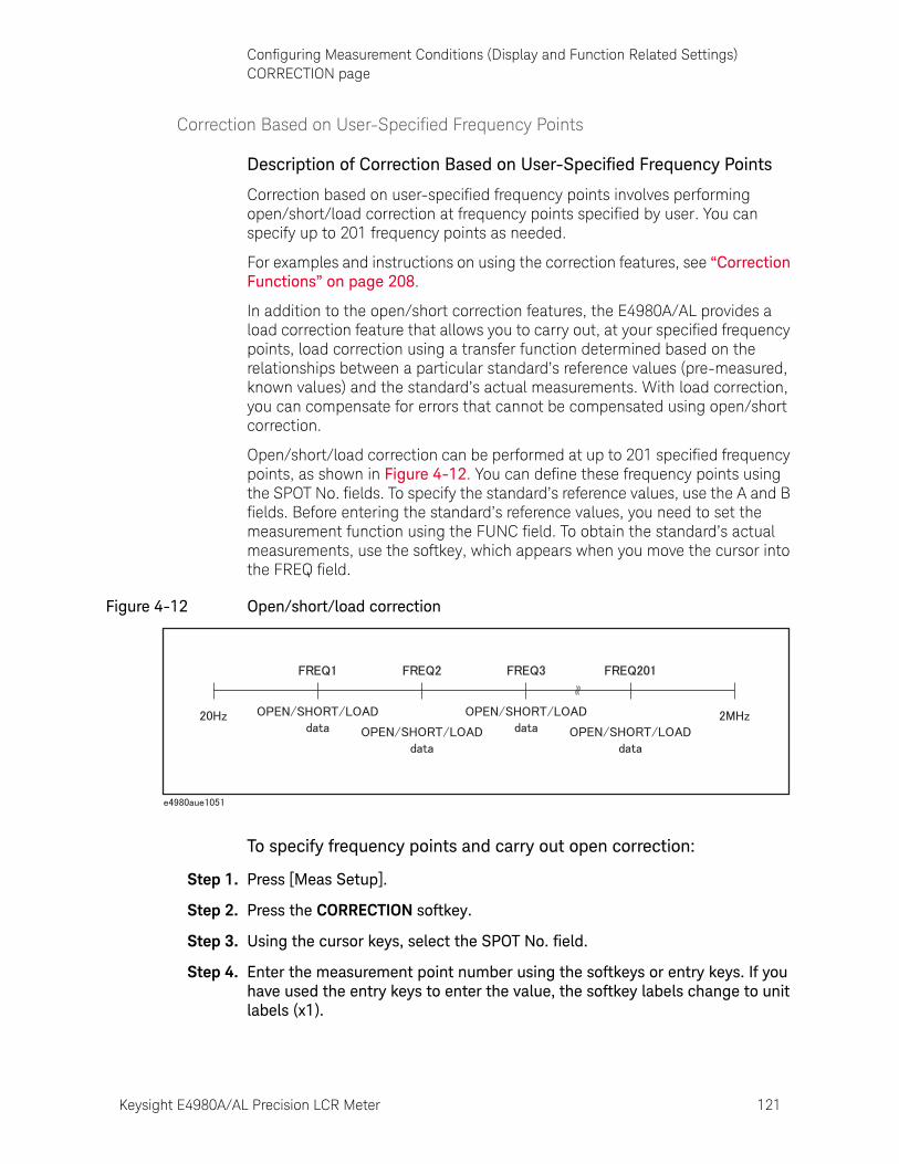
Keysight E4980A/AL Precision LCR Meter 121
Configuring Measurement Conditions (Display and Function Related Settings)CORRECTION page
Correction Based on User-Specified Frequency Points
Description of Correction Based on User-Specified Frequency Points
Correction based on user-specified frequency points involves performing open/short/load correction at frequency points specified by user. You can specify up to 201 frequency points as needed.
For examples and instructions on using the correction features, see “Correction Functions” on page 208.
In addition to the open/short correction features, the E4980A/AL provides a load correction feature that allows you to carry out, at your specified frequency points, load correction using a transfer function determined based on the relationships between a particular standard’s reference values (pre-measured, known values) and the standard’s actual measurements. With load correction, you can compensate for errors that cannot be compensated using open/short correction.
Open/short/load correction can be performed at up to 201 specified frequency points, as shown in Figure 4-12. You can define these frequency points using the SPOT No. fields. To specify the standard’s reference values, use the A and B fields. Before entering the standard’s reference values, you need to set the measurement function using the FUNC field. To obtain the standard’s actual measurements, use the softkey, which appears when you move the cursor into the FREQ field.
Figure 4-12 Open/short/load correction
To specify frequency points and carry out open correction:
Step 1. Press [Meas Setup].
Step 2. Press the CORRECTION softkey.
Step 3. Using the cursor keys, select the SPOT No. field.
Step 4. Enter the measurement point number using the softkeys or entry keys. If you have used the entry keys to enter the value, the softkey labels change to unit labels (x1).
122 Keysight E4980A/AL Precision LCR Meter
Configuring Measurement Conditions (Display and Function Related Settings)CORRECTION page
4-
You can specify up to 201 measurement points.
Step 5. Using the cursor keys, select the FREQ field.
Step 6. Enter the frequency using the entry keys. When you have entered the frequency, the softkey labels change to unit labels (Hz, kHz, MHz).
Step 7. Press the ON softkey.
Step 8. Connect the UNKNOWN terminal and the text fixture with no DUT connected.
Step 9. Press the MEAS OPEN softkey.
• During the measurement, an “OPEN measurement in progress” message is shown on the display.
• When the measurement has finished, the “OPEN measurement in progress” message disappears.
Softkey Description
INCR ++ Increments the measurement point number in steps of 10.
INCR + Increments the measurement point number in steps of 1.
DECR - Decrements the measurement point number in steps of 1.
DECR -- Decrements the measurement point number in steps of 10.
Keysight E4980A/AL Precision LCR Meter 123
Configuring Measurement Conditions (Display and Function Related Settings)CORRECTION page
• During the measurement, the ABORT softkey is shown. Use this key when you want to abort open correction
Step 10. Repeat Step 3 to Step 9 until you have specified all of your desired measurement points.
Step 11. Move the cursor into the OPEN field.
Step 12. Press the ON key to enable the open correction feature.
The E4980A/AL do not have a functionality to check whether the OPEN correction data is valid or not. Any OPEN correction data can be set, even if work-related mistakes are made in measuring for the OPEN correction.
For example,
- improper OPEN is used.
- setting up the OPEN state and SHORT state inversely.
- the OPEN is connected incompletely.
- fixture or cable is connected incompletely.
- previous correction data is used.
- after correction, different length cable/different fixture is connected or settings of frequency/level is changed.
If OPEN correction data is invalid, it may cause inappropriate measurements without showing warning message. Be careful about the connection of appropriate OPEN state. OPEN A and OPEN B are measured values when the OPEN correction is performed. You can check the measured values.
If "E43 Measurement failed" error is displayed during the OPEN correction, measure the OPEN state (disable OPEN correction[OPEN OFF]) at frequency you select and check if the following conditions happen. If one of them happens, try its suggestion.
"ALC unable to regulate" warning message is displayed (suggestion: turn off ALC)
"Signal source overload" warning message is displayed (suggestion: reduce test signal)
"Overload" is displayed (Measurement result becomes overload) (suggestion: check cabling/fixturing)
124 Keysight E4980A/AL Precision LCR Meter
Configuring Measurement Conditions (Display and Function Related Settings)CORRECTION page
4-
To specify frequency points and carry out short correction:
Step 1. Press [Meas Setup].
Step 2. Press the CORRECTION softkey.
Step 3. Using the cursor keys, select the SPOT No. field.
Step 4. Enter the measurement point number using the softkeys or entry keys. If you have used the entry keys to enter the value, the softkey labels change to unit labels (x1).
You can specify up to 201 measurement points.
Step 5. Using the cursor keys, select the FREQ field.
Step 6. Enter the frequency using the entry keys. When you enter the frequency, the softkey labels change to unit labels (Hz, kHz, MHz).
Step 7. Press the ON softkey.
Step 8. Connect the UNKNOWN terminal and the test fixture and short-circuit the HIGH and LOW test terminals.
Step 9. Press the MEAS SHORT softkey.
• During the measurement, a “SHORT measurement in progress” message is shown on the display.
• When the measurement has finished, the “SHORT measurement in progress” message disappears.
Softkey Description
INCR ++ Increments the measurement point number in steps of 10.
INCR + Increments the measurement point number in steps of 1.
DECR - Decrements the measurement point number in steps of 1.
DECR -- Decrements the measurement point number in steps of 10.
Keysight E4980A/AL Precision LCR Meter 125
Configuring Measurement Conditions (Display and Function Related Settings)CORRECTION page
• During the measurement, the ABORT softkey is shown. Use this key when you want to abort short correction
Step 10. Repeat Step 3 to Step 9 until you have specified all of your desired measurement points.
Step 11. Move the cursor into the SHORT field.
Step 12. Press the ON key to enable the short correction feature.
The E4980A/AL do not have a functionality to check whether the SHORT correction data is valid or not. Any SHORT correction data can be set, even if work-related mistakes are made in measuring for the SHORT correction. For example,
- improper SHORT is used.
- setting up the OPEN state and SHORT state inversely.
- the SHORT is connected incompletely.
- fixture or cable is connected incompletely.
- previous correction data is used.
- after correction, different length cable/different fixture is connected or settings of frequency/level is changed.
If SHORT correction data is invalid, it may cause inappropriate measurements without showing warning message. Be careful about the connection of appropriate SHORT state. SHORT A and SHORT B are measured values when the SHORT correction is performed. You can check the measured values.
If "E43 Measurement failed" error is displayed during the SHORT correction, measure the SHORT state (disable SHORT correction[SHORT OFF]) at frequency you select and check if the following conditions happen. If one of them happens, try its suggestion.
"ALC unable to regulate" warning message is displayed (suggestion: turn off ALC)
"Signal source overload" warning message is displayed (suggestion: reduce test signal)
"Overload" is displayed (Measurement result becomes overload) (suggestion: check cabling/fixturing)
126 Keysight E4980A/AL Precision LCR Meter
Configuring Measurement Conditions (Display and Function Related Settings)CORRECTION page
4-
To specify frequency points and carry out load correction:
Step 1. Press [Meas Setup].
Step 2. Press the CORRECTION softkey.
Step 3. Using the cursor keys, select the SPOT No. field.
Step 4. Enter the measurement point number using the softkeys or entry keys. If you use the entry keys to enter the value, the softkey labels change to unit labels (x1).
You can specify up to 201 measurement points.
Step 5. Using the cursor keys, select the FREQ field.
Step 6. Enter the frequency using the entry keys. When you enter the frequency, the softkey labels change to unit labels (Hz, kHz, MHz).
Step 7. Press the ON softkey.
Step 8. Move the cursor into the REF A field.
Step 9. Enter the known value of the standard’s primary parameter using the softkeys or entry keys.
Step 10. Move the cursor into the REF B field.
Step 11. Enter the known value of the standard’s secondary parameter using the softkeys or entry keys.
Step 12. Move the cursor into the FREQ field.
Step 13. Connect the standard to the UNKNOWN terminal.
Step 14. Press the MEAS LOAD softkey.
• During the measurement, a “LOAD measurement in progress” message is shown on the display.
• When the measurement has finished, the “LOAD measurement in progress” message disappears.
Softkey Description
INCR ++ Increments the measurement point number in steps of 10.
INCR + Increments the measurement point number in steps of 1.
DECR - Decrements the measurement point number in steps of 1.
DECR -- Decrements the measurement point number in steps of 10.
Keysight E4980A/AL Precision LCR Meter 127
Configuring Measurement Conditions (Display and Function Related Settings)CORRECTION page
• During the measurement, the ABORT softkey is shown. Use this key when you want to abort load correction
Step 15. Repeat Step 3 to Step 14 until you have specified all of your desired measurement points.
Step 16. Move the cursor into the LOAD field.
Step 17. Press the ON key to enable the load correction feature.
The E4980A/AL do not have a functionality to check whether the LOAD correction data is valid or not. Any LOAD correction data can be set, even if work-related mistakes are made in measuring for the LOAD correction.
For example,
- improper LOAD is used.
- setting up the OPEN/SHORT state and LOAD state inversely.
- the LOAD is connected incompletely.
- fixture or cable is connected incompletely.
- previous correction data is used.
- after correction, different length cable/different fixture is connected or settings of frequency/level is changed.
If LOAD correction data is invalid, it may cause inappropriate measurements without showing warning message. Be careful about the connection of appropriate LOAD state. LOAD A and LOAD B are measured values when the LOAD correction is performed. You can check the measured values.
If "E43 Measurement failed" error is displayed during the LOAD correction, measure the LOAD state (disable LOAD correction[LOAD OFF]) at frequency you select and check if the following conditions happen. If one of them happens, try its suggestion.
"ALC unable to regulate" warning message is displayed (suggestion: turn off ALC)
"Signal source overload" warning message is displayed (suggestion: reduce test signal)
"Overload" is displayed (Measurement result becomes overload) (suggestion: check cabling/fixturing)
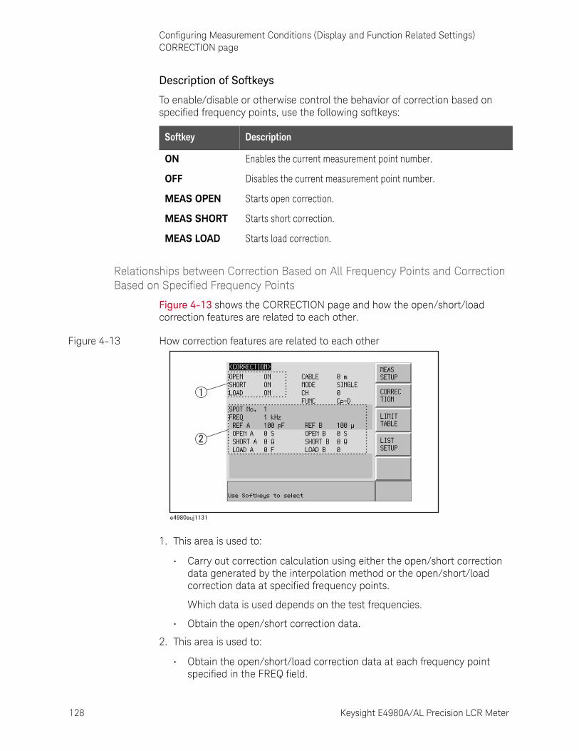
128 Keysight E4980A/AL Precision LCR Meter
Configuring Measurement Conditions (Display and Function Related Settings)CORRECTION page
4-
Description of Softkeys
To enable/disable or otherwise control the behavior of correction based on specified frequency points, use the following softkeys:
Relationships between Correction Based on All Frequency Points and Correction Based on Specified Frequency Points
Figure 4-13 shows the CORRECTION page and how the open/short/load correction features are related to each other.
Figure 4-13 How correction features are related to each other
1. This area is used to:
• Carry out correction calculation using either the open/short correction data generated by the interpolation method or the open/short/load correction data at specified frequency points.
Which data is used depends on the test frequencies.
• Obtain the open/short correction data.
2. This area is used to:
• Obtain the open/short/load correction data at each frequency point specified in the FREQ field.
Softkey Description
ON Enables the current measurement point number.
OFF Disables the current measurement point number.
MEAS OPEN Starts open correction.
MEAS SHORT Starts short correction.
MEAS LOAD Starts load correction.

Keysight E4980A/AL Precision LCR Meter 129
Configuring Measurement Conditions (Display and Function Related Settings)CORRECTION page
• Enable or disable the open/short/load correction data at each frequency point specified in the FREQ field.
The following tables show how correction data elements are related to each other when the correction features are enabled in the OPEN, SHORT, and LOAD fields. Correction data elements are selected based on the number of measurement points.
• When test frequency point is equal to the frequency point specified in FREQ field:
• When test frequency point is NOT equal to the frequency point specified in FREQ field:
Correction Frequency point specified in FREQ field
ON OFF
OPEN: ON
SHORT: ON
LOAD: ON
User-specified
User-specified
User-specified
Interpolated
Interpolated
X
Correction Frequency point specified in FREQ field
ON OFF
OPEN: ON
SHORT: ON
LOAD: ON
Interpolated
Interpolated
X
Interpolated
Interpolated
X
User-specified
Correction data at your specified frequency point are used.
Interpolated Correction data generated by interpolation are used.
X Correction is not performed even when correction features are enabled in OPEN, SHORT, and LOAD fields.
When you specify a frequency point whose frequency value is identical to that of an existing frequency point and turn on the correction feature for both points, the frequency point with the smaller measurement point number (SPOT No. field) is selected as the correction data.
130 Keysight E4980A/AL Precision LCR Meter
Configuring Measurement Conditions (Display and Function Related Settings)CORRECTION page
4-
Reading/Writing Correction Data
The E4980A/AL allows you to read and write the correction data.
To write the correction data:
Step 1. Press the [Meas Setup] key.
Step 2. Press the CORRECTION softkey.
Step 3. Using the cursor keys, select the SPOT No. field and enter the measurement point number.
Step 4. Using the cursor keys, select the FREQ field and enter the frequency.
Step 5. Using the cursor keys, select these fields: OPEN A, SHORT A, LOAD A, OPEN B, SHORT B, and LOAD B.
Step 6. Enter the correction data using the softkeys or entry keys. If you use the entry keys to enter the value, the softkey labels change to unit labels (p, n, u, m, x1).
Keysight E4980A/AL Precision LCR Meter 131
Configuring Measurement Conditions (Display and Function Related Settings)CORRECTION page
Measurement Functions for the Standard
Functional Description
When you perform load correction, you have to use the reference value of the standard (either known or pre-measured value). You can select only one of the available measurement functions as the reference value. For more information on the available measurement functions, see “Measurement Function” on page 47.
The load correction feature compensates for error by using a transmission coefficient derived from the relationship between the standard’s reference value and the actual measurement. Your selected measurement function is used solely for the calculation of the transmission function.
To set up the measurement function:
Step 1. Press [Meas Setup].
Step 2. Press the CORRECTION softkey.
Step 3. Using the cursor keys, select the FUNC field.
Step 4. Using the cursor keys, select the primary parameter.
Step 5. If there is a secondary parameter and you are presented with another list of measurement parameters, select one of them by using the softkeys.
For more information on measurement parameters, see “Measurement Function” on page 47.
132 Keysight E4980A/AL Precision LCR Meter
Configuring Measurement Conditions (Display and Function Related Settings)CORRECTION page
4-
Selecting Single/Multiple Correction Mode
Functional Description
When equipped with Option 301 (Scanner Interface), E4980A/AL can store up to 128 sets of open/short/load correction data. In addition, it can store one set of the standard’s reference value data at a specified frequency point. In multiple correction mode, you can switch among up to 128 data sets to carry out correction. Note that the correction features default to single correction mode.
In multiple correction mode, the channel number for which correction data are selected is displayed on the right-hand side of the CH indicator.
To set up single/multiple correction mode:
Step 1. Press [Meas Setup].
Step 2. Press the CORRECTION softkey.
Step 3. Using the cursor keys, select the MODE field.
Step 4. Use the following softkeys:
When you use multiple correction mode, you cannot perform open/short correction by the interpolation method (open/short correction at particular frequency points) but must perform correction at specified frequency points.
User-specified frequency points can be configured separately between single and multiple correction modes.
Softkey Description
SINGLE Turns ON single correction mode.
MULTI Turns ON multiple correction mode.
For more information on measurement parameters, see “Measurement Function” on page 47.
When Option 301 (Scanner Interface) is not installed and you attempt to switch to multiple correction mode, a Scanner I/F not installed error message appears in the system message area.

Keysight E4980A/AL Precision LCR Meter 133
Configuring Measurement Conditions (Display and Function Related Settings)CORRECTION page
Selecting the Cable Length
Functional Description
The E4980A/AL has four reference planes (points): the UNKNOWN terminal (0 m), the tip of the 16048A/B test lead (1 m), the tip of the 16048D test lead (2 m), and the tip of the 16048E test lead (4 m). These points serve as the basis for the measurement accuracy.
When you select a cable length of 0 m, you have to use the UNKNOWN terminal to interconnect the outer contacts of lead wires Hcur, Hpot, Lpot, and Lcur.
When you select a cable length of 1 m, you have to use the tip of the 16048A/B 1m test lead to interconnect the outer contacts of lead wires Hcur, Hpot, Lpot, and Lcur.
When you select a cable length of 2 m, you have to use the tip of the 16048D 2m test lead to interconnect the outer contacts of lead wires Hcur, Hpot, Lpot, and Lcur.
When you select a cable length of 4 m, you have to use the tip of the 16048E 4m test lead to interconnect the outer contacts of lead wires Hcur, Hpot, Lpot, and Lcur.
The four-terminal pair structure is terminated at the tip of your selected cable length. When you use the 16048A/B/D/E test lead, connect the supplied terminal plate to the tip of the cable to terminate the four-terminal pair structure.
To select the cable length:
Step 1. Press [Meas Setup].
Step 2. Press the CORRECTION softkey.
Step 3. Using the cursor keys, select the CABLE field.
Step 4. Use the following softkeys:
Softkey Description
0 m Sets the cable length to 0 m (none).
1 m Sets the cable length to 1 m.
2 m Sets the cable length to 2 m.
4 m Sets the cable length to 4 m.
134 Keysight E4980A/AL Precision LCR Meter
Configuring Measurement Conditions (Display and Function Related Settings)LIMIT TABLE SETUP Page
4-
LIMIT TABLE SETUP PagePressing the [Meas Setup] key followed by the LIMIT TABLE softkey opens the LIMIT TABLE SETUP page. The LIMIT TABLE SETUP page allows you to configure the E4980A/AL’s built-in comparator.
The built-in comparator can sort DUTs into a maximum 10 levels (BIN1 through BIN9 and OUT OF BINS) using up to nine sets of primary parameter limits along with one set of secondary parameter limits. In addition, DUTs that fall within the primary parameter limits but are out of the secondary parameter limits can be sorted into an auxiliary bin.
The comparator counts DUTs up to 999999. When this number is reached, the screen shows “-----” and the counting stops.
To take full advantage of the comparator, we recommend that you equip the E4980A/AL with the handler interface option for use in conjunction with the comparator. The limits for bin sorting can only be configured on the LIMIT TABLE SETUP.
In this page, you can configure each of the following controls with the cursor placed in the corresponding field (denoted in parentheses).
• Measurement function (FUNC field)
• Comparator limit mode (MODE field)
• Tolerance mode nominal value (NOM field)
• Auxiliary bin ON/OFF (AUX field)
• Comparator ON/OFF (COMP field)
• Beep feature (BEEP field)
• Low limit for each bin (LOW field)
• High limit for each bin (HIGH field)
Figure 4-14 shows the fields available on this page along with the softkeys corresponding to them.
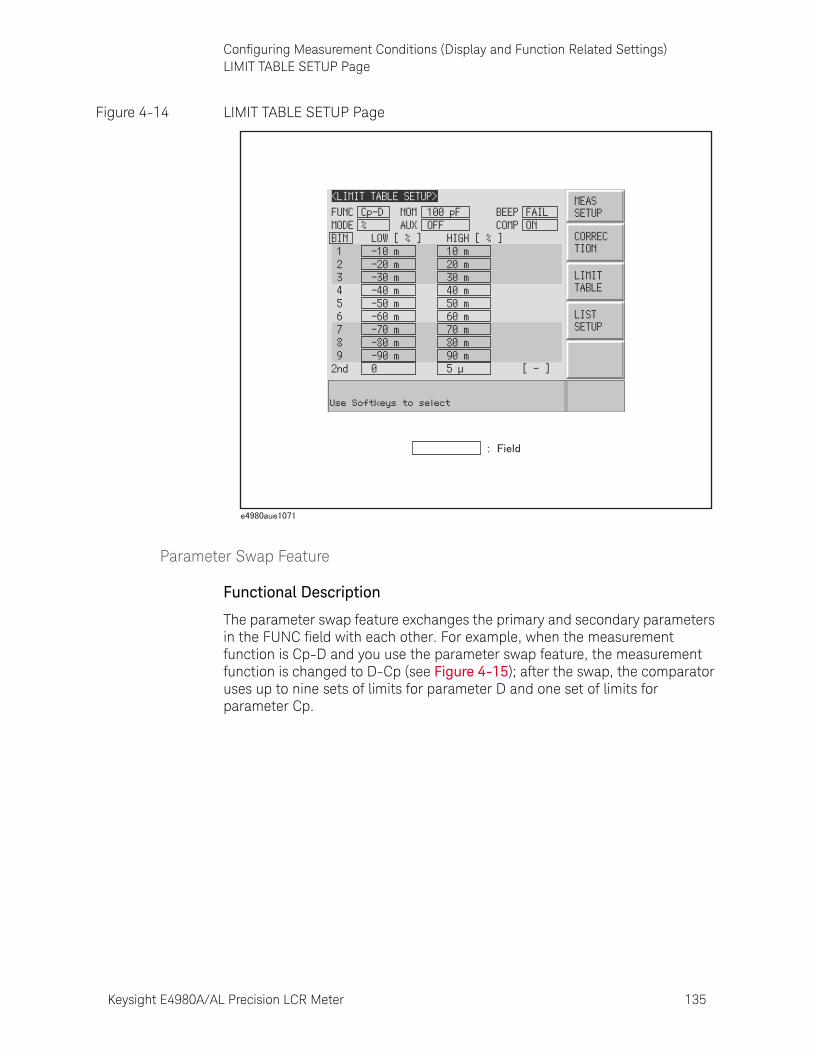
Keysight E4980A/AL Precision LCR Meter 135
Configuring Measurement Conditions (Display and Function Related Settings)LIMIT TABLE SETUP Page
Figure 4-14 LIMIT TABLE SETUP Page
Parameter Swap Feature
Functional Description
The parameter swap feature exchanges the primary and secondary parameters in the FUNC field with each other. For example, when the measurement function is Cp-D and you use the parameter swap feature, the measurement function is changed to D-Cp (see Figure 4-15); after the swap, the comparator uses up to nine sets of limits for parameter D and one set of limits for parameter Cp.
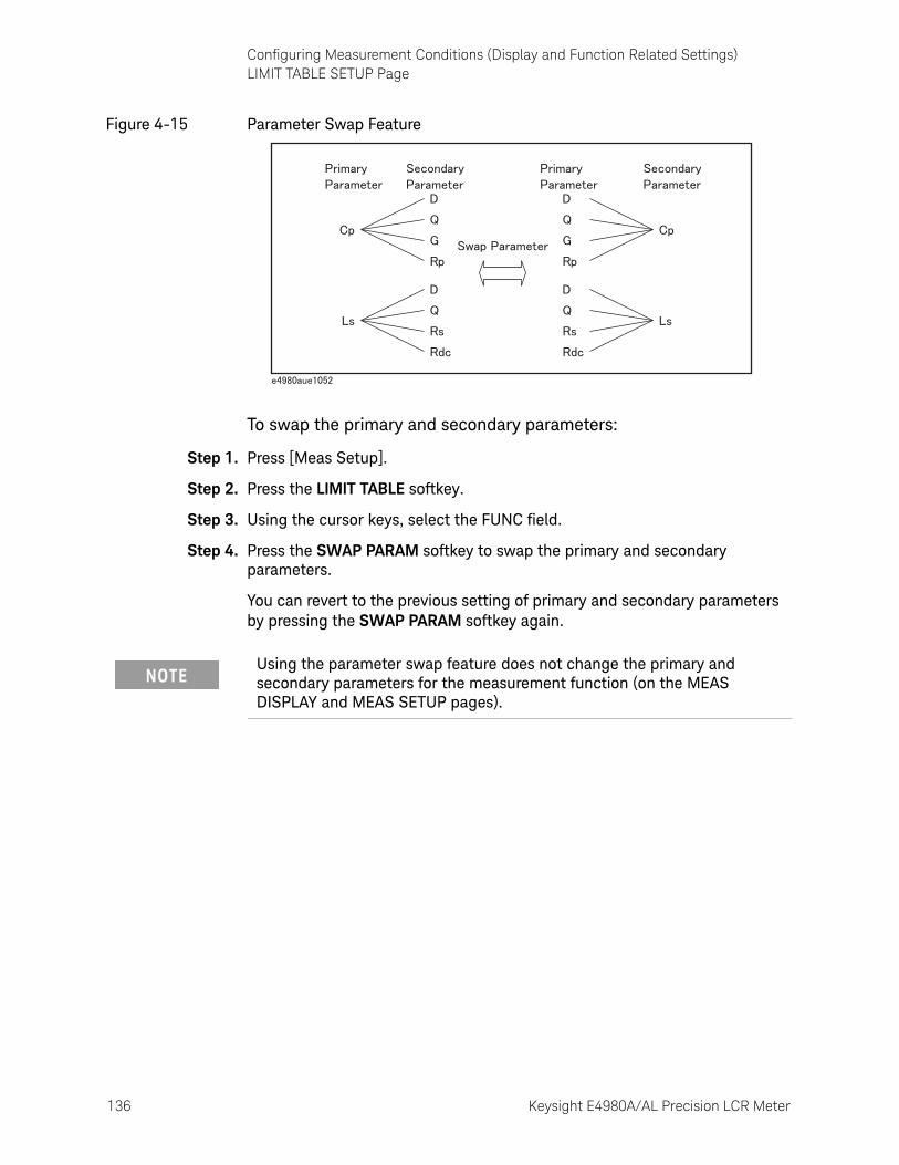
136 Keysight E4980A/AL Precision LCR Meter
Configuring Measurement Conditions (Display and Function Related Settings)LIMIT TABLE SETUP Page
4-
Figure 4-15 Parameter Swap Feature
To swap the primary and secondary parameters:
Step 1. Press [Meas Setup].
Step 2. Press the LIMIT TABLE softkey.
Step 3. Using the cursor keys, select the FUNC field.
Step 4. Press the SWAP PARAM softkey to swap the primary and secondary parameters.
You can revert to the previous setting of primary and secondary parameters by pressing the SWAP PARAM softkey again.
Using the parameter swap feature does not change the primary and secondary parameters for the measurement function (on the MEAS DISPLAY and MEAS SETUP pages).

Keysight E4980A/AL Precision LCR Meter 137
Configuring Measurement Conditions (Display and Function Related Settings)LIMIT TABLE SETUP Page
Comparator Limit Mode
Functional Description
You can specify the primary parameter limit values in one of the following two ways (see Figure 4-16):
• Tolerance mode
In tolerance mode, the comparison limit values are based on the deviations from the specified nominal value, which can be specified in the NOM field. You configure the tolerance mode limit values as a deviation percentage (%) or absolute parameter value.
• Sequential mode
In sequential mode, the comparison limit values are based on the absolute value of the measurement. When you configure these limit values, you have to first define the minimum value and then the maximum value.
Figure 4-16 Tolerance mode and sequential mode
When you use tolerance mode, you have to assign the narrowest limit value (range) to bin 1, the second narrowest range to bin2, and so on, finally assigning the widest range to the last bin. Should the range assigned to bin 1 be wider than those assigned to subsequent bins, all DUTs would be sorted into bin 1.
In tolerance mode, the lower limit need not be smaller than the nominal value, and the upper limit value need not be larger than the nominal value. As you can see in Figure 4-17, as sorting occurs, there may be blanks or overlaps.
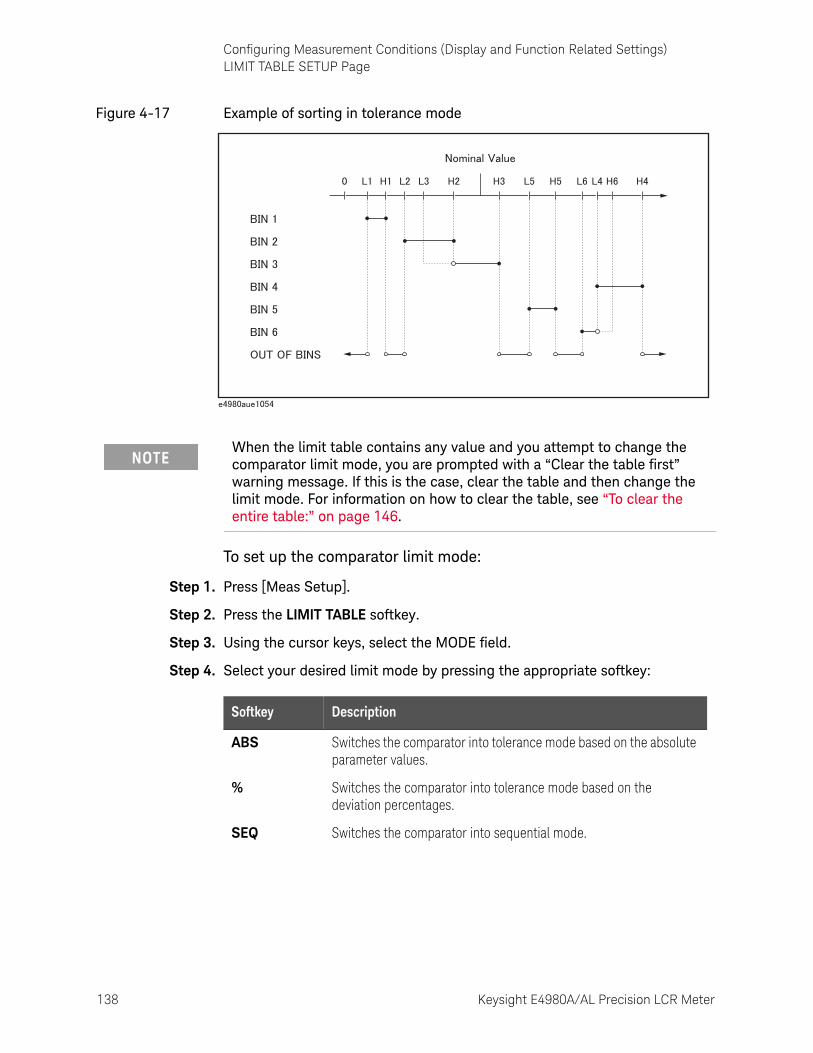
138 Keysight E4980A/AL Precision LCR Meter
Configuring Measurement Conditions (Display and Function Related Settings)LIMIT TABLE SETUP Page
4-
Figure 4-17 Example of sorting in tolerance mode
To set up the comparator limit mode:
Step 1. Press [Meas Setup].
Step 2. Press the LIMIT TABLE softkey.
Step 3. Using the cursor keys, select the MODE field.
Step 4. Select your desired limit mode by pressing the appropriate softkey:
When the limit table contains any value and you attempt to change the comparator limit mode, you are prompted with a “Clear the table first” warning message. If this is the case, clear the table and then change the limit mode. For information on how to clear the table, see “To clear the entire table:” on page 146.
Softkey Description
ABS Switches the comparator into tolerance mode based on the absolute parameter values.
% Switches the comparator into tolerance mode based on the deviation percentages.
SEQ Switches the comparator into sequential mode.
Keysight E4980A/AL Precision LCR Meter 139
Configuring Measurement Conditions (Display and Function Related Settings)LIMIT TABLE SETUP Page
Tolerance Mode Nominal Value
Functional Description
When you use tolerance mode as the limit mode for the primary parameter, you have to configure the nominal value.
The nominal value can be configured even when the primary parameter limit mode is sequential, but this does not affect sorting.
To configure the nominal value:
Step 1. Press [Meas Setup].
Step 2. Press the LIMIT TABLE softkey.
Step 3. Using the cursor keys, select the NOM field.
Step 4. Enter the nominal value using the softkeys or entry keys. If you use the entry keys to enter the value, the softkey labels change to unit labels (n, u, m, x1, k).
When you use a negative nominal value in deviation tolerance mode, be sure to set the lower limit to a value higher than the upper limit because the lower limit value becomes larger than the upper limit value when they are converted into absolute values.
Softkey Description
INCR ++ Increments the nominal value in steps of your selected number (1, 2, 5, 10, 20, 50, 100, 200, 500).
INCR + Increments the nominal value in steps of 1.
DECR - Decrements the nominal value in steps of 1.
DECR -- Decrements the nominal value in steps of your selected number(1, 2, 5, 10, 20, 50, 100, 200, 500).
140 Keysight E4980A/AL Precision LCR Meter
Configuring Measurement Conditions (Display and Function Related Settings)LIMIT TABLE SETUP Page
4-
Turning On/Off the Comparator
Functional Description
The E4980A/AL’s built-in comparator can sort DUTs into a maximum 10 levels (bin 1 through bin 9 and OUT OF BINS) using up to nine sets of primary parameter limits along with one set of secondary parameter limits.
In addition, DUTs that fall within the primary parameter limits but are out of the secondary parameter limits can be sorted into an auxiliary bin.
To turn on or off the comparator:
Step 1. Press [Meas Setup].
Step 2. Press the LIMIT TABLE softkey.
Step 3. Using the cursor keys, select the COMP field.
Step 4. Turn on or off the comparator by pressing the appropriate softkey:
Softkey Description
ON Turns ON the comparator.
OFF Turns OFF the comparator.
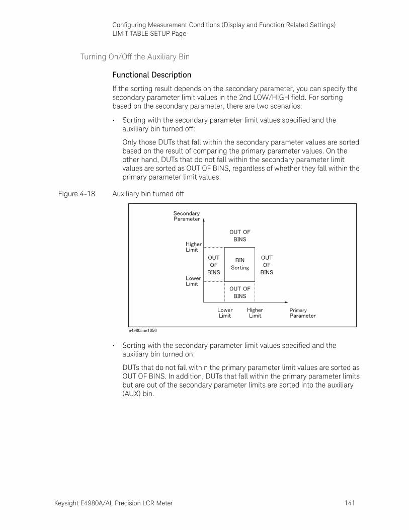
Keysight E4980A/AL Precision LCR Meter 141
Configuring Measurement Conditions (Display and Function Related Settings)LIMIT TABLE SETUP Page
Turning On/Off the Auxiliary Bin
Functional Description
If the sorting result depends on the secondary parameter, you can specify the secondary parameter limit values in the 2nd LOW/HIGH field. For sorting based on the secondary parameter, there are two scenarios:
• Sorting with the secondary parameter limit values specified and the auxiliary bin turned off:
Only those DUTs that fall within the secondary parameter values are sorted based on the result of comparing the primary parameter values. On the other hand, DUTs that do not fall within the secondary parameter limit values are sorted as OUT OF BINS, regardless of whether they fall within the primary parameter limit values.
Figure 4-18 Auxiliary bin turned off
• Sorting with the secondary parameter limit values specified and the auxiliary bin turned on:
DUTs that do not fall within the primary parameter limit values are sorted as OUT OF BINS. In addition, DUTs that fall within the primary parameter limits but are out of the secondary parameter limits are sorted into the auxiliary (AUX) bin.
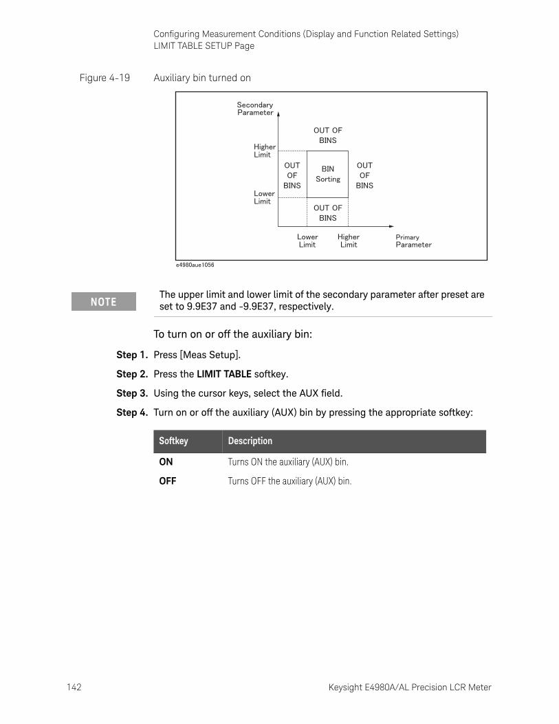
142 Keysight E4980A/AL Precision LCR Meter
Configuring Measurement Conditions (Display and Function Related Settings)LIMIT TABLE SETUP Page
4-
Figure 4-19 Auxiliary bin turned on
To turn on or off the auxiliary bin:
Step 1. Press [Meas Setup].
Step 2. Press the LIMIT TABLE softkey.
Step 3. Using the cursor keys, select the AUX field.
Step 4. Turn on or off the auxiliary (AUX) bin by pressing the appropriate softkey:
The upper limit and lower limit of the secondary parameter after preset are set to 9.9E37 and -9.9E37, respectively.
Softkey Description
ON Turns ON the auxiliary (AUX) bin.
OFF Turns OFF the auxiliary (AUX) bin.
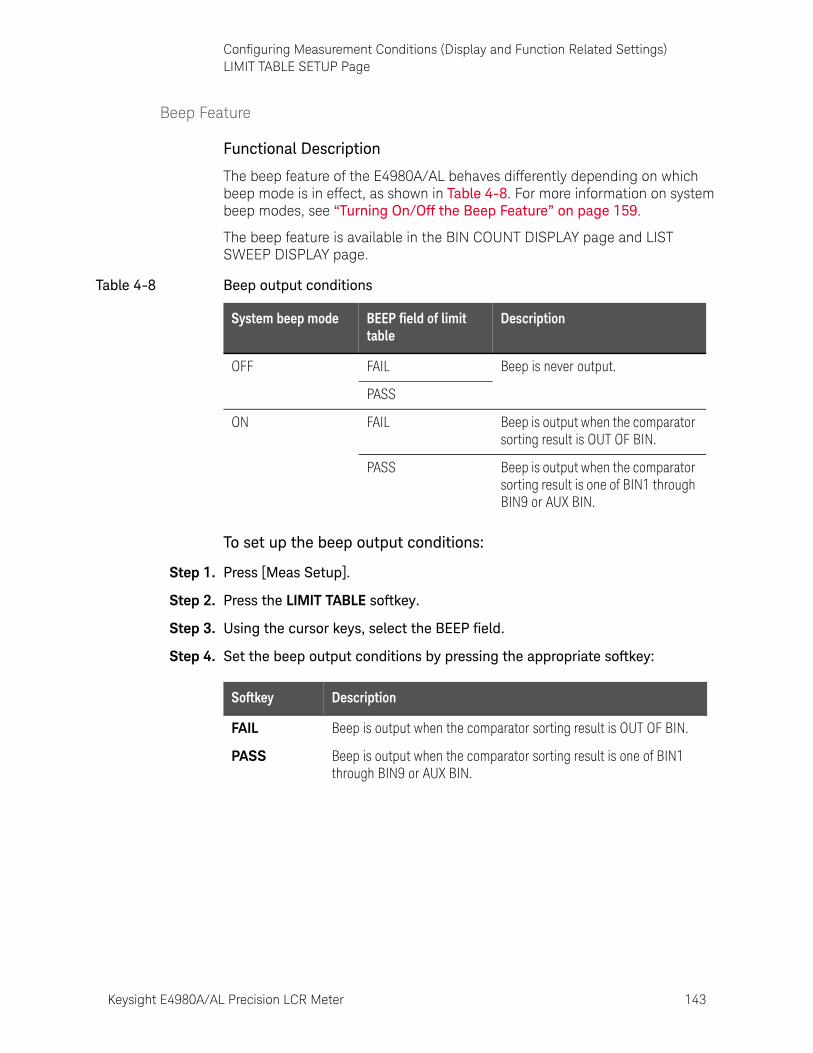
Keysight E4980A/AL Precision LCR Meter 143
Configuring Measurement Conditions (Display and Function Related Settings)LIMIT TABLE SETUP Page
Beep Feature
Functional Description
The beep feature of the E4980A/AL behaves differently depending on which beep mode is in effect, as shown in Table 4-8. For more information on system beep modes, see “Turning On/Off the Beep Feature” on page 159.
The beep feature is available in the BIN COUNT DISPLAY page and LIST SWEEP DISPLAY page.
To set up the beep output conditions:
Step 1. Press [Meas Setup].
Step 2. Press the LIMIT TABLE softkey.
Step 3. Using the cursor keys, select the BEEP field.
Step 4. Set the beep output conditions by pressing the appropriate softkey:
Table 4-8 Beep output conditions
System beep mode BEEP field of limit table
Description
OFF FAIL Beep is never output.
PASS
ON FAIL Beep is output when the comparator sorting result is OUT OF BIN.
PASS Beep is output when the comparator sorting result is one of BIN1 through BIN9 or AUX BIN.
Softkey Description
FAIL Beep is output when the comparator sorting result is OUT OF BIN.
PASS Beep is output when the comparator sorting result is one of BIN1 through BIN9 or AUX BIN.
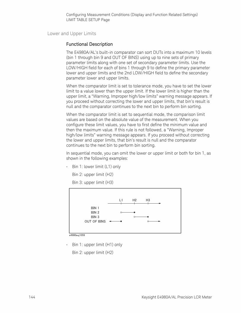
144 Keysight E4980A/AL Precision LCR Meter
Configuring Measurement Conditions (Display and Function Related Settings)LIMIT TABLE SETUP Page
4-
Lower and Upper Limits
Functional Description
The E4980A/AL’s built-in comparator can sort DUTs into a maximum 10 levels (bin 1 through bin 9 and OUT OF BINS) using up to nine sets of primary parameter limits along with one set of secondary parameter limits. Use the LOW/HIGH field for each of bins 1 through 9 to define the primary parameter lower and upper limits and the 2nd LOW/HIGH field to define the secondary parameter lower and upper limits.
When the comparator limit is set to tolerance mode, you have to set the lower limit to a value lower than the upper limit. If the lower limit is higher than the upper limit, a “Warning, Improper high/low limits” warning message appears. If you proceed without correcting the lower and upper limits, that bin’s result is null and the comparator continues to the next bin to perform bin sorting.
When the comparator limit is set to sequential mode, the comparison limit values are based on the absolute value of the measurement. When you configure these limit values, you have to first define the minimum value and then the maximum value. If this rule is not followed, a “Warning, Improper high/low limits” warning message appears. If you proceed without correcting the lower and upper limits, that bin’s result is null and the comparator continues to the next bin to perform bin sorting.
In sequential mode, you can omit the lower or upper limit or both for bin 1, as shown in the following examples:
• Bin 1: lower limit (L1) only
Bin 2: upper limit (H2)
Bin 3: upper limit (H3)
• Bin 1: upper limit (H1) only
Bin 2: upper limit (H2)
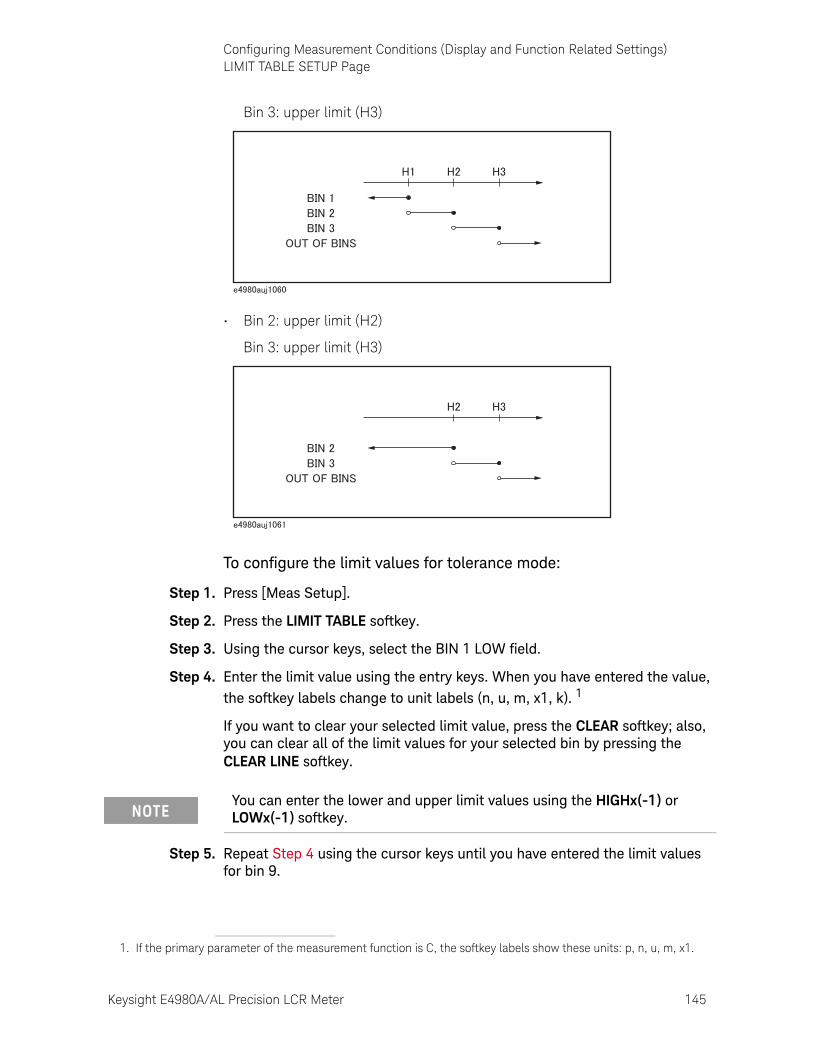
Keysight E4980A/AL Precision LCR Meter 145
Configuring Measurement Conditions (Display and Function Related Settings)LIMIT TABLE SETUP Page
Bin 3: upper limit (H3)
• Bin 2: upper limit (H2)
Bin 3: upper limit (H3)
To configure the limit values for tolerance mode:
Step 1. Press [Meas Setup].
Step 2. Press the LIMIT TABLE softkey.
Step 3. Using the cursor keys, select the BIN 1 LOW field.
Step 4. Enter the limit value using the entry keys. When you have entered the value, the softkey labels change to unit labels (n, u, m, x1, k). 1
If you want to clear your selected limit value, press the CLEAR softkey; also, you can clear all of the limit values for your selected bin by pressing the CLEAR LINE softkey.
Step 5. Repeat Step 4 using the cursor keys until you have entered the limit values for bin 9.
1. If the primary parameter of the measurement function is C, the softkey labels show these units: p, n, u, m, x1.
You can enter the lower and upper limit values using the HIGHx(-1) or LOWx(-1) softkey.
146 Keysight E4980A/AL Precision LCR Meter
Configuring Measurement Conditions (Display and Function Related Settings)LIMIT TABLE SETUP Page
4-
Step 6. Move the cursor into the 2nd LOW field and enter the lower limit value for the secondary parameter.
Step 7. Move the cursor into the 2nd HIGH field and enter the upper limit value for the secondary parameter.
To configure the limit values for sequential mode:
Step 1. Press [Meas Setup].
Step 2. Press the LIMIT TABLE softkey.
Step 3. Using the cursor keys, select the BIN 1 LOW field.
Step 4. Enter the limit value using the entry keys. When you enter the value, the softkey labels change to unit labels (p, n, u, m, x1).
If you want to clear your selected limit value, press the CLEAR softkey; also, you can clear all the limit values for your selected bin by pressing the CLEAR LINE softkey.
Step 5. Repeat Step 4 using the cursor keys until you have entered the upper limit for bin 9 (BIN 9 HIGH).
Step 6. Move the cursor into the 2nd LOW field and enter the Lower limit value for the secondary parameter.
Step 7. Move the cursor into the 2nd HIGH field and enter the upper limit value for the secondary parameter.
To clear the entire table:
Step 1. Press [Meas Setup].
Step 2. Press the LIMIT TABLE softkey.
Step 3. Using the cursor keys, select the BIN field.
Step 4. Press the CLEAR TABLE softkey.
The LOW field accepts an entry for bin1 only and does not accept an entry for bins 2 through 9. The value entered into the HIGH field for bin 1 is used as the lower limit for bin 2, but the LOW field for bin 2 displays no value.
You can enter the lower or upper limit values using the HIGHx(-1) or LOWx(-1) softkey.
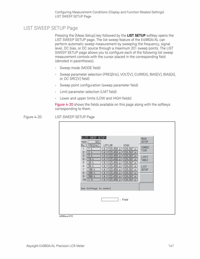
Keysight E4980A/AL Precision LCR Meter 147
Configuring Measurement Conditions (Display and Function Related Settings)LIST SWEEP SETUP Page
LIST SWEEP SETUP PagePressing the [Meas Setup] key followed by the LIST SETUP softkey opens the LIST SWEEP SETUP page. The list sweep feature of the E4980A/AL can perform automatic sweep measurement by sweeping the frequency, signal level, DC bias, or DC source through a maximum 201 sweep points. The LIST SWEEP SETUP page allows you to configure each of the following list sweep measurement controls with the cursor placed in the corresponding field (denoted in parentheses).
• Sweep mode (MODE field)
• Sweep parameter selection (FREQ[Hz], VOLT[V], CURR[A], BIAS[V], BIAS[A], or DC SRC[V] field)
• Sweep point configuration (sweep parameter field)
• Limit parameter selection (LMT field)
• Lower and upper limits (LOW and HIGH fields)
Figure 4-20 shows the fields available on this page along with the softkeys corresponding to them.
Figure 4-20 LIST SWEEP SETUP Page
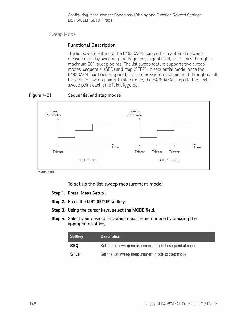
148 Keysight E4980A/AL Precision LCR Meter
Configuring Measurement Conditions (Display and Function Related Settings)LIST SWEEP SETUP Page
4-
Sweep Mode
Functional Description
The list sweep feature of the E4980A/AL can perform automatic sweep measurement by sweeping the frequency, signal level, or DC bias through a maximum 201 sweep points. The list sweep feature supports two sweep modes: sequential (SEQ) and step (STEP). In sequential mode, once the E4980A/AL has been triggered, it performs sweep measurement throughout all the defined sweep points. In step mode, the E4980A/AL steps to the next sweep point each time it is triggered.
Figure 4-21 Sequential and step modes
To set up the list sweep measurement mode:
Step 1. Press [Meas Setup].
Step 2. Press the LIST SETUP softkey.
Step 3. Using the cursor keys, select the MODE field.
Step 4. Select your desired list sweep measurement mode by pressing the appropriate softkey:
Softkey Description
SEQ Set the list sweep measurement mode to sequential mode.
STEP Set the list sweep measurement mode to step mode.
Keysight E4980A/AL Precision LCR Meter 149
Configuring Measurement Conditions (Display and Function Related Settings)LIST SWEEP SETUP Page
List Sweep Parameters
Functional Description
The sweep parameter used in list sweep measurement can be measurement frequency, signal level, DC bias, or DC source. Use the sweep point field to specify the list sweep measurement parameter.
To specify the list sweep measurement parameter:
Step 1. Press [Meas Setup].
Step 2. Press the LIST SETUP softkey.
Step 3. Using the cursor keys, select the sweep parameter field.
Step 4. Select your desired list sweep measurement parameter by pressing the appropriate softkey:
Softkey Description
FREQ [Hz] Uses frequency as the list sweep parameter.
LEVEL [V] Uses voltage as the list sweep parameter.
LEVEL [A] Uses current as the list sweep parameter.
BIAS [V] Uses DC bias voltage as the list sweep parameter.
BIAS [A] Uses DC bias current as the list sweep parameter.
DC SRC [V] Uses DC source as the list sweep parameter.
When the sweep parameter is set using the SCPI commands, the secondary sweep parameter can be set. In addition, the measurement range can be set for the secondary parameter. For details, refer to “:LIST:STIMulus:TYPE” on page 362.
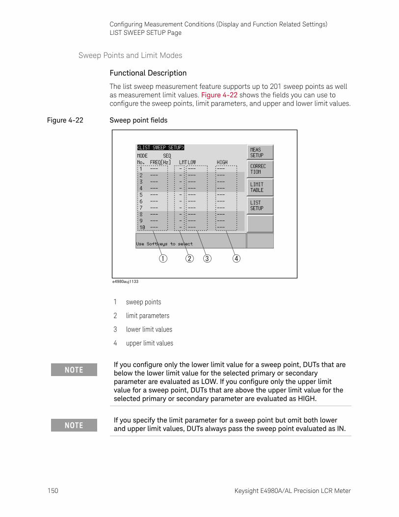
150 Keysight E4980A/AL Precision LCR Meter
Configuring Measurement Conditions (Display and Function Related Settings)LIST SWEEP SETUP Page
4-
Sweep Points and Limit Modes
Functional Description
The list sweep measurement feature supports up to 201 sweep points as well as measurement limit values. Figure 4-22 shows the fields you can use to configure the sweep points, limit parameters, and upper and lower limit values.
Figure 4-22 Sweep point fields
1 sweep points
2 limit parameters
3 lower limit values
4 upper limit values
If you configure only the lower limit value for a sweep point, DUTs that are below the lower limit value for the selected primary or secondary parameter are evaluated as LOW. If you configure only the upper limit value for a sweep point, DUTs that are above the upper limit value for the selected primary or secondary parameter are evaluated as HIGH.
If you specify the limit parameter for a sweep point but omit both lower and upper limit values, DUTs always pass the sweep point evaluated as IN.
Keysight E4980A/AL Precision LCR Meter 151
Configuring Measurement Conditions (Display and Function Related Settings)LIST SWEEP SETUP Page
To configure the sweep points:
Step 1. Press [Meas Setup].
Step 2. Press the LIST SETUP softkey.
Step 3. Using the cursor keys, select the sweep parameter field.
Step 4. Using the cursor keys, select one of the sweep point fields (1 through 201).
Also, you can use the following softkeys as needed:
Step 5. Enter the sweep point value using the entry keys. When you enter the value, the softkey labels change to unit labels (u, m, x1, k, M).
Step 6. Using the cursor keys, select the LMT field.
Step 7. Configure the limit parameter by pressing the appropriate softkey:
Under the following conditions (unless the measurement data status is 0), DUTs are always evaluated as LOW.
• An overload is detected.
• A signal is detected exceeding the allowable limit of the signal source.
• The automatic level control (ALC) feature does not work.
The upper limit value must be larger than the lower limit value. If this rule is not followed, a “Warning, Improper high/low limits” warning message appears, and the DUTs are evaluated as follows:
• If the result is below the lower limit, they are evaluated as LOW.
• If the result is equal to or above the lower limit, they are evaluated as HIGH.
Softkey Description
CLEAR LINE Clears the limit value.
FILL LINEAR See “Sweep Parameter Auto-completion” on page 153.
FILL LOG See “Sweep Parameter Auto-completion” on page 153.
NEXT PAGE Proceeds to the next page.
PREV PAGE Returns to the previous page.
Softkey Description
A Uses the measurement function’s primary parameter as the limit parameter.
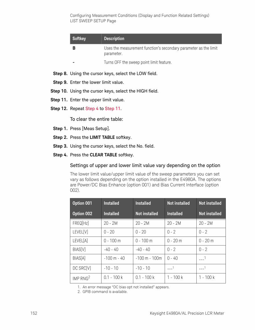
152 Keysight E4980A/AL Precision LCR Meter
Configuring Measurement Conditions (Display and Function Related Settings)LIST SWEEP SETUP Page
4-
Step 8. Using the cursor keys, select the LOW field.
Step 9. Enter the lower limit value.
Step 10. Using the cursor keys, select the HIGH field.
Step 11. Enter the upper limit value.
Step 12. Repeat Step 4 to Step 11.
To clear the entire table:
Step 1. Press [Meas Setup].
Step 2. Press the LIMIT TABLE softkey.
Step 3. Using the cursor keys, select the No. field.
Step 4. Press the CLEAR TABLE softkey.
Settings of upper and lower limit value vary depending on the option
The lower limit value/upper limit value of the sweep parameters you can set vary as follows depending on the option installed in the E4980A. The options are Power/DC Bias Enhance (option 001) and Bias Current Interface (option 002).
B Uses the measurement function’s secondary parameter as the limit parameter.
- Turns OFF the sweep point limit feature.
Softkey Description
Option 001 Installed Installed Not installed Not installed
Option 002 Installed Not installed Installed Not installed
FREQ[Hz] 20 - 2M 20 - 2M 20 - 2M 20 - 2M
LEVEL[V] 0 - 20 0 - 20 0 - 2 0 - 2
LEVEL[A] 0 - 100 m 0 - 100 m 0 - 20 m 0 - 20 m
BIAS[V] -40 - 40 -40 - 40 0 - 2 0 - 2
BIAS[A] -100 m - 40 -100 m - 100m 0 - 40 ---1
DC SRC[V] -10 - 10 -10 - 10 ---1 ---1
IMP RNG2 0.1 - 100 k 0.1 - 100 k 1 - 100 k 1 - 100 k
1. An error message “DC bias opt not installed” appears.2. GPIB command is available.
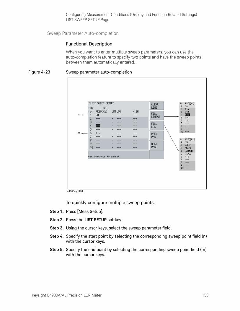
Keysight E4980A/AL Precision LCR Meter 153
Configuring Measurement Conditions (Display and Function Related Settings)LIST SWEEP SETUP Page
Sweep Parameter Auto-completion
Functional Description
When you want to enter multiple sweep parameters, you can use the auto-completion feature to specify two points and have the sweep points between them automatically entered.
Figure 4-23 Sweep parameter auto-completion
To quickly configure multiple sweep points:
Step 1. Press [Meas Setup].
Step 2. Press the LIST SETUP softkey.
Step 3. Using the cursor keys, select the sweep parameter field.
Step 4. Specify the start point by selecting the corresponding sweep point field (n) with the cursor keys.
Step 5. Specify the end point by selecting the corresponding sweep point field (m) with the cursor keys.
154 Keysight E4980A/AL Precision LCR Meter
Configuring Measurement Conditions (Display and Function Related Settings)LIST SWEEP SETUP Page
4-
Step 6. Have all sweep points between the start and end points automatically entered by pressing the appropriate softkey:
Softkey Description
FILL LINEAR Linearly enters all sweep points between the start and end points.
FILL LOG Logarithmically enters all sweep points between the start and end points. 1
1. Available only when using the frequency as the list sweep parameter.
If n is not found, calculation is made on the assumption that n=1 represents the minimum value.
If m is not found, calculation is made on the assumption that m=201 represents the maximum value.
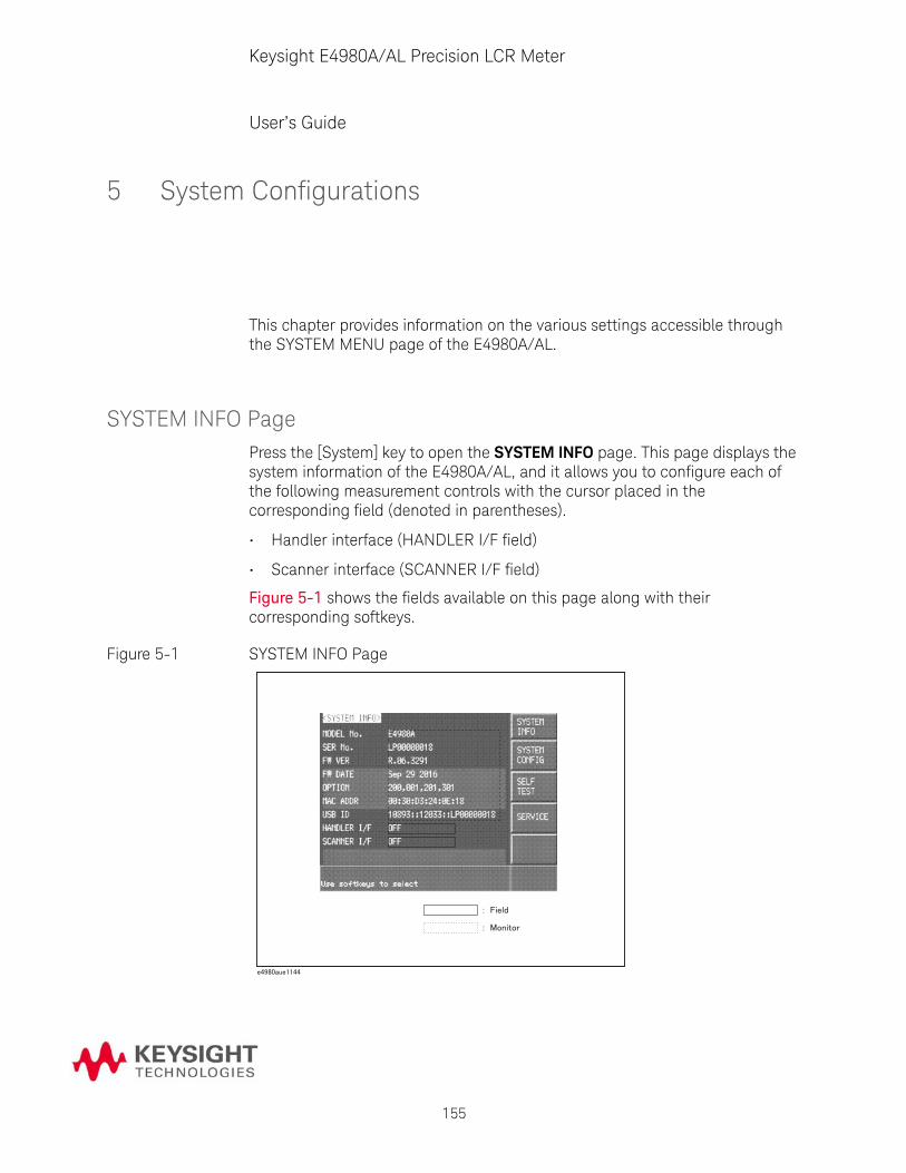
155
Keysight E4980A/AL Precision LCR Meter
User’s Guide
5 System Configurations
This chapter provides information on the various settings accessible through the SYSTEM MENU page of the E4980A/AL.
SYSTEM INFO PagePress the [System] key to open the SYSTEM INFO page. This page displays the system information of the E4980A/AL, and it allows you to configure each of the following measurement controls with the cursor placed in the corresponding field (denoted in parentheses).
• Handler interface (HANDLER I/F field)
• Scanner interface (SCANNER I/F field)
Figure 5-1 shows the fields available on this page along with their corresponding softkeys.
Figure 5-1 SYSTEM INFO Page
156 Keysight E4980A/AL Precision LCR Meter
System ConfigurationsSYSTEM INFO Page
5-
Handler Interface
Functional Description
When equipped with Option 201 Handler Interface, the E4980A/AL can interact with the handler. The 36-contact Amphenol connector on the rear panel is used to connect the interface, through which control input/output signals and comparator bin sorting result signals are communicated.
For more information on available options, see Appendix E , “Handler Interface,” on page 465.
When the E4980A/AL is not equipped with the Handler Interface, the HANDLER I/F field shows a “NOT INSTALLED” message and the ON/OFF settings are not available.
Softkey Description
ON Turns ON the handler interface feature.
OFF Turns OFF the handler interface feature.

Keysight E4980A/AL Precision LCR Meter 157
System ConfigurationsSYSTEM INFO Page
Scanner Interface
Functional Description
When equipped with Option 301 Scanner Interface, the E4980A/AL supports multi-channel correction. The 14-contact Amphenol connector on the rear panel is used to connect the interface, through which control output signals and multi-channel correction channel selector signals are communicated.
For more information on available options, see Appendix F , “Scanner Interface,” on page 493.
Monitor Information
The SYSTEM INFO page displays the following monitor information. None of this information can be edited on the SYSTEM INFO page.
When the E4980A/AL is not equipped with the Scanner Interface, the SCANNER I/F field shows a “NOT INSTALLED” message and the ON/OFF settings are not available.
Softkey Description
ON Turns ON the scanner interface feature.
OFF Turns OFF the scanner interface feature.
Monitor Information
Description
MODEL No. Displays the model number, i.e. E4980A/AL.
SER No. Displays the serial number of the instrument.
FW VER Displays the version of the firmware installed in the instrument.
FW DATE Displays the date of the instrument’s most recent update.
OPTION Displays the option number of any option installed in the instrument.
MAC ADDR Displays the MAC address.
USB ID Displays the USB address.
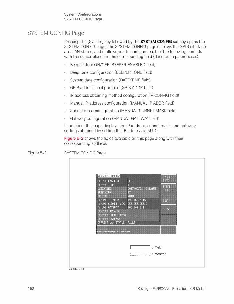
158 Keysight E4980A/AL Precision LCR Meter
System ConfigurationsSYSTEM CONFIG Page
5-
SYSTEM CONFIG PagePressing the [System] key followed by the SYSTEM CONFIG softkey opens the SYSTEM CONFIG page. The SYSTEM CONFIG page displays the GPIB interface and LAN status, and it allows you to configure each of the following controls with the cursor placed in the corresponding field (denoted in parentheses).
• Beep feature ON/OFF (BEEPER ENABLED field)
• Beep tone configuration (BEEPER TONE field)
• System date configuration (DATE/TIME field)
• GPIB address configuration (GPIB ADDR field)
• IP address obtaining method configuration (IP CONFIG field)
• Manual IP address configuration (MANUAL IP ADDR field)
• Subnet mask configuration (MANUAL SUBNET MASK field)
• Gateway configuration (MANUAL GATEWAY field)
In addition, this page displays the IP address, subnet mask, and gateway settings obtained by setting the IP address to AUTO.
Figure 5-2 shows the fields available on this page along with their corresponding softkeys.
Figure 5-2 SYSTEM CONFIG Page

Keysight E4980A/AL Precision LCR Meter 159
System ConfigurationsSYSTEM CONFIG Page
Turning On/Off the Beep Feature
Functional Description
The E4980A/AL has a beep feature that generates beeps when one or more of the following conditions occur:
• An error message or warning message has appeared.
• The instrument has completed open/short correction.
• The instrument has completed open/short/load correction at user-specified frequency points.
• The DUT has failed the limit test or has been sorted as OUT OF BIN/AUX BIN by the comparator. 1
• The DUT has passed the limit test or has been sorted into one of bins 1 through 9 by the comparator. 1
• You have turned on/off the key lock.
Regardless of whether the beep feature is on or off, beeps are generated whenever:
• E4980A/AL starts up.
• You change the beep tone through the front panel.
To set up the beep feature:
Step 1. Press [System].
Step 2. Press the SYSTEM CONFIG softkey.
Step 3. Use the cursor keys to select the BEEPER ENABLED field.
Step 4. Turn on or off the beep feature by pressing the appropriate softkey:
1. You can use the BEEP field on the LIST SWEEP SETUP page or the COMP:BEEP command to turn on/off the beep feature for the comparator.
The beep feature does not support volume control.
Softkey Description
ON Turns ON the beep feature.
OFF Turns OFF the beep feature.
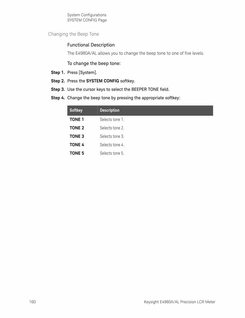
160 Keysight E4980A/AL Precision LCR Meter
System ConfigurationsSYSTEM CONFIG Page
5-
Changing the Beep Tone
Functional Description
The E4980A/AL allows you to change the beep tone to one of five levels.
To change the beep tone:
Step 1. Press [System].
Step 2. Press the SYSTEM CONFIG softkey.
Step 3. Use the cursor keys to select the BEEPER TONE field.
Step 4. Change the beep tone by pressing the appropriate softkey:
Softkey Description
TONE 1 Selects tone 1.
TONE 2 Selects tone 2.
TONE 3 Selects tone 3.
TONE 4 Selects tone 4.
TONE 5 Selects tone 5.
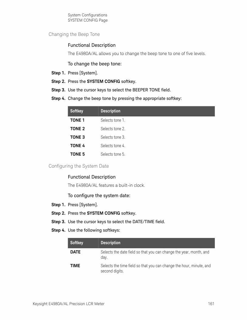
Keysight E4980A/AL Precision LCR Meter 161
System ConfigurationsSYSTEM CONFIG Page
Changing the Beep Tone
Functional Description
The E4980A/AL allows you to change the beep tone to one of five levels.
To change the beep tone:
Step 1. Press [System].
Step 2. Press the SYSTEM CONFIG softkey.
Step 3. Use the cursor keys to select the BEEPER TONE field.
Step 4. Change the beep tone by pressing the appropriate softkey:
Configuring the System Date
Functional Description
The E4980A/AL features a built-in clock.
To configure the system date:
Step 1. Press [System].
Step 2. Press the SYSTEM CONFIG softkey.
Step 3. Use the cursor keys to select the DATE/TIME field.
Step 4. Use the following softkeys:
Softkey Description
TONE 1 Selects tone 1.
TONE 2 Selects tone 2.
TONE 3 Selects tone 3.
TONE 4 Selects tone 4.
TONE 5 Selects tone 5.
Softkey Description
DATE Selects the date field so that you can change the year, month, and day.
TIME Selects the time field so that you can change the hour, minute, and second digits.
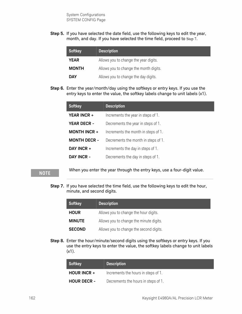
162 Keysight E4980A/AL Precision LCR Meter
System ConfigurationsSYSTEM CONFIG Page
5-
Step 5. If you have selected the date field, use the following keys to edit the year, month, and day. If you have selected the time field, proceed to Step 7.
Step 6. Enter the year/month/day using the softkeys or entry keys. If you use the entry keys to enter the value, the softkey labels change to unit labels (x1).
Step 7. If you have selected the time field, use the following keys to edit the hour, minute, and second digits.
Step 8. Enter the hour/minute/second digits using the softkeys or entry keys. If you use the entry keys to enter the value, the softkey labels change to unit labels (x1).
Softkey Description
YEAR Allows you to change the year digits.
MONTH Allows you to change the month digits.
DAY Allows you to change the day digits.
Softkey Description
YEAR INCR + Increments the year in steps of 1.
YEAR DECR - Decrements the year in steps of 1.
MONTH INCR + Increments the month in steps of 1.
MONTH DECR - Decrements the month in steps of 1.
DAY INCR + Increments the day in steps of 1.
DAY INCR - Decrements the day in steps of 1.
When you enter the year through the entry keys, use a four-digit value.
Softkey Description
HOUR Allows you to change the hour digits.
MINUTE Allows you to change the minute digits.
SECOND Allows you to change the second digits.
Softkey Description
HOUR INCR + Increments the hours in steps of 1.
HOUR DECR - Decrements the hours in steps of 1.
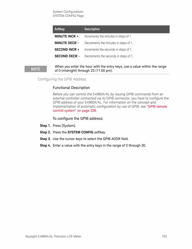
Keysight E4980A/AL Precision LCR Meter 163
System ConfigurationsSYSTEM CONFIG Page
Configuring the GPIB Address
Functional Description
Before you can control the E4980A/AL by issuing GPIB commands from an external controller connected via its GPIB connector, you have to configure the GPIB address of your E4980A/AL. For information on the concept and implementation of automatic configuration by use of GPIB, see “GPIB remote control system” on page 226.
To configure the GPIB address:
Step 1. Press [System].
Step 2. Press the SYSTEM CONFIG softkey.
Step 3. Use the cursor keys to select the GPIB ADDR field.
Step 4. Enter a value with the entry keys in the range of 0 through 30.
MINUTE INCR + Increments the minutes in steps of 1.
MINUTE DECR - Decrements the minutes in steps of 1.
SECOND INCR + Increments the seconds in steps of 1.
SECOND DECR - Decrements the seconds in steps of 1.
When you enter the hour with the entry keys, use a value within the range of 0 (midnight) through 23 (11:00 pm).
Softkey Description
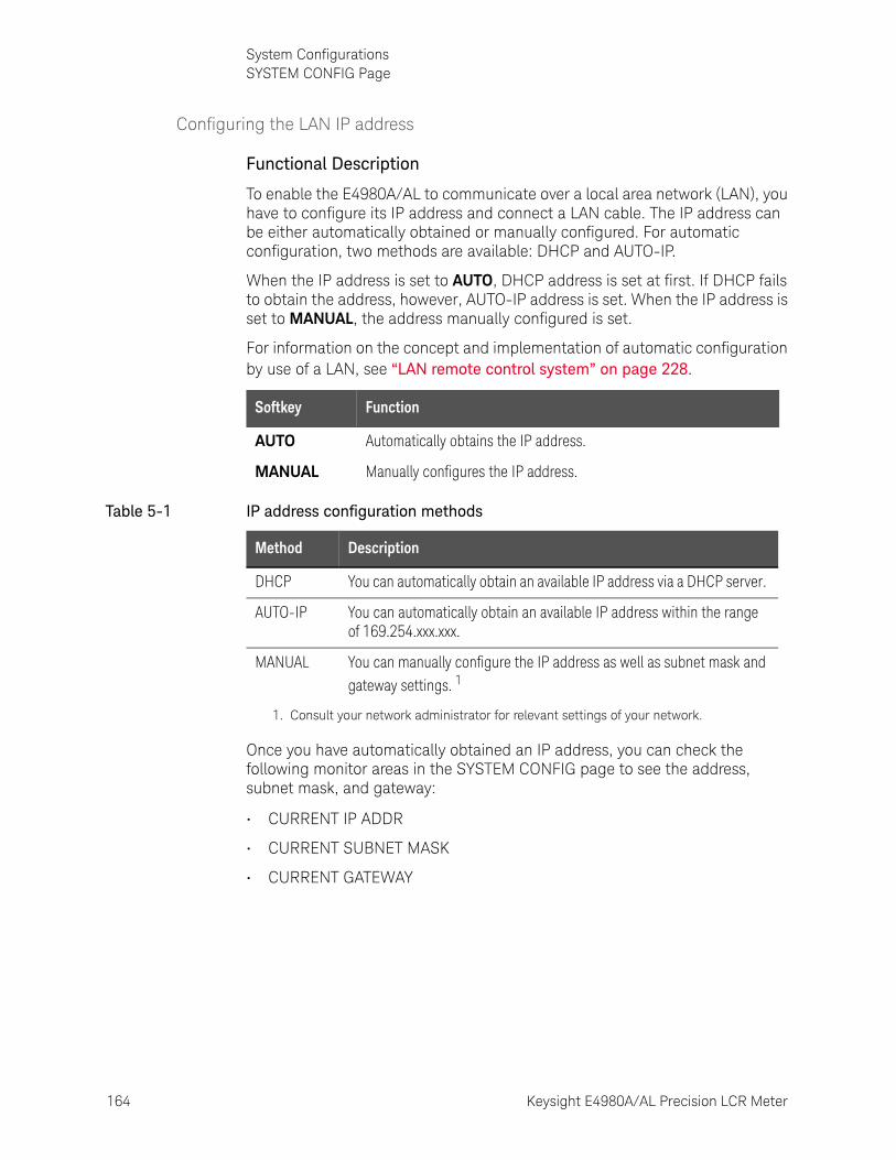
164 Keysight E4980A/AL Precision LCR Meter
System ConfigurationsSYSTEM CONFIG Page
5-
Configuring the LAN IP address
Functional Description
To enable the E4980A/AL to communicate over a local area network (LAN), you have to configure its IP address and connect a LAN cable. The IP address can be either automatically obtained or manually configured. For automatic configuration, two methods are available: DHCP and AUTO-IP.
When the IP address is set to AUTO, DHCP address is set at first. If DHCP fails to obtain the address, however, AUTO-IP address is set. When the IP address is set to MANUAL, the address manually configured is set.
For information on the concept and implementation of automatic configuration by use of a LAN, see “LAN remote control system” on page 228.
Once you have automatically obtained an IP address, you can check the following monitor areas in the SYSTEM CONFIG page to see the address, subnet mask, and gateway:
• CURRENT IP ADDR
• CURRENT SUBNET MASK
• CURRENT GATEWAY
Softkey Function
AUTO Automatically obtains the IP address.
MANUAL Manually configures the IP address.
Table 5-1 IP address configuration methods
Method Description
DHCP You can automatically obtain an available IP address via a DHCP server.
AUTO-IP You can automatically obtain an available IP address within the range of 169.254.xxx.xxx.
MANUAL You can manually configure the IP address as well as subnet mask and gateway settings. 1
1. Consult your network administrator for relevant settings of your network.
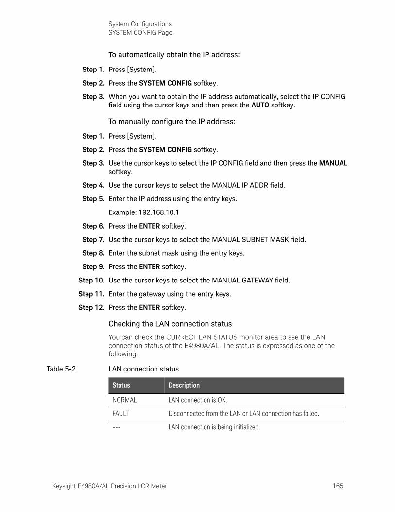
Keysight E4980A/AL Precision LCR Meter 165
System ConfigurationsSYSTEM CONFIG Page
To automatically obtain the IP address:
Step 1. Press [System].
Step 2. Press the SYSTEM CONFIG softkey.
Step 3. When you want to obtain the IP address automatically, select the IP CONFIG field using the cursor keys and then press the AUTO softkey.
To manually configure the IP address:
Step 1. Press [System].
Step 2. Press the SYSTEM CONFIG softkey.
Step 3. Use the cursor keys to select the IP CONFIG field and then press the MANUAL softkey.
Step 4. Use the cursor keys to select the MANUAL IP ADDR field.
Step 5. Enter the IP address using the entry keys.
Example: 192.168.10.1
Step 6. Press the ENTER softkey.
Step 7. Use the cursor keys to select the MANUAL SUBNET MASK field.
Step 8. Enter the subnet mask using the entry keys.
Step 9. Press the ENTER softkey.
Step 10. Use the cursor keys to select the MANUAL GATEWAY field.
Step 11. Enter the gateway using the entry keys.
Step 12. Press the ENTER softkey.
Checking the LAN connection status
You can check the CURRECT LAN STATUS monitor area to see the LAN connection status of the E4980A/AL. The status is expressed as one of the following:
Table 5-2 LAN connection status
Status Description
NORMAL LAN connection is OK.
FAULT Disconnected from the LAN or LAN connection has failed.
--- LAN connection is being initialized.
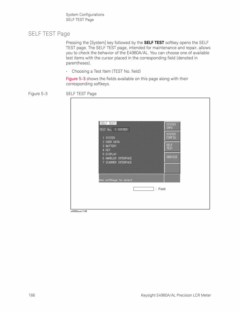
166 Keysight E4980A/AL Precision LCR Meter
System ConfigurationsSELF TEST Page
5-
SELF TEST PagePressing the [System] key followed by the SELF TEST softkey opens the SELF TEST page. The SELF TEST page, intended for maintenance and repair, allows you to check the behavior of the E4980A/AL. You can choose one of available test items with the cursor placed in the corresponding field (denoted in parentheses).
• Choosing a Test Item (TEST No. field)
Figure 5-3 shows the fields available on this page along with their corresponding softkeys.
Figure 5-3 SELF TEST Page

Keysight E4980A/AL Precision LCR Meter 167
System ConfigurationsSELF TEST Page
Choosing a Test Item
Functional Description
The E4980A/AL can run the following self tests:
To run a self test:
For step-by-step instructions, see “Daily Checks (Executing the self-test)” on page 421.
Table 5-3
Test item Description
SYSTEM Checks the entire system, A1/A2/A3 boards, system calibration data, and so on.
USER DATA Checks the GPIB/LAN configurations, instrument configuration information, instrument calibration data, and scanner calibration data.
BATTERY Checks the internal batteries.
KEY Checks the font panel keys. (Visual confirmation only; no pass/fail result shown on screen.)
DISPLAY Checks the font panel LEDs and LCD. (Visual confirmation only; no pass/fail result shown on screen.)
HANDLER INTERFACE
Checks the handler interface. (Visual confirmation only; no pass/fail result shown on screen.)
SCANNER INTERFACE
Checks the scanner interface. (Visual confirmation only; no pass/fail result shown on screen.)
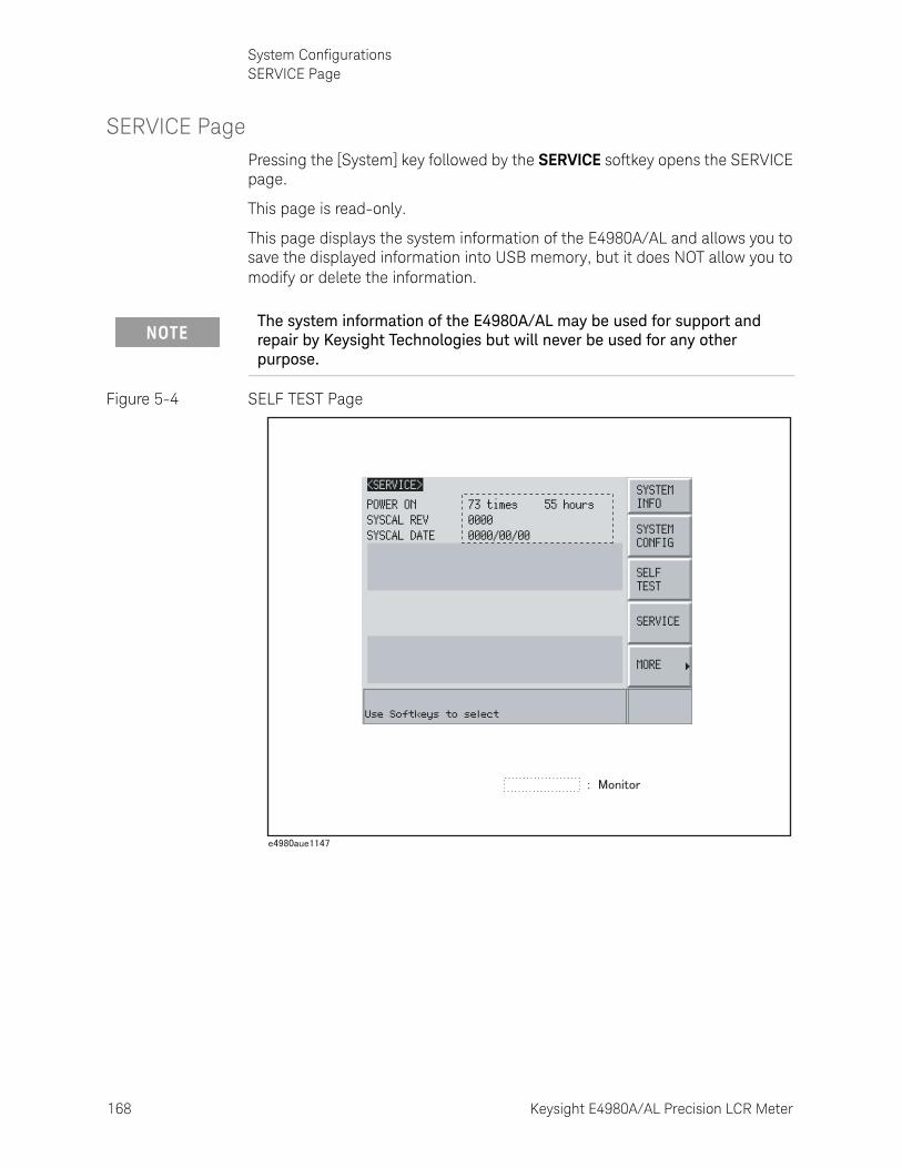
168 Keysight E4980A/AL Precision LCR Meter
System ConfigurationsSERVICE Page
5-
SERVICE PagePressing the [System] key followed by the SERVICE softkey opens the SERVICE page.
This page is read-only.
This page displays the system information of the E4980A/AL and allows you to save the displayed information into USB memory, but it does NOT allow you to modify or delete the information.
Figure 5-4 SELF TEST Page
The system information of the E4980A/AL may be used for support and repair by Keysight Technologies but will never be used for any other purpose.
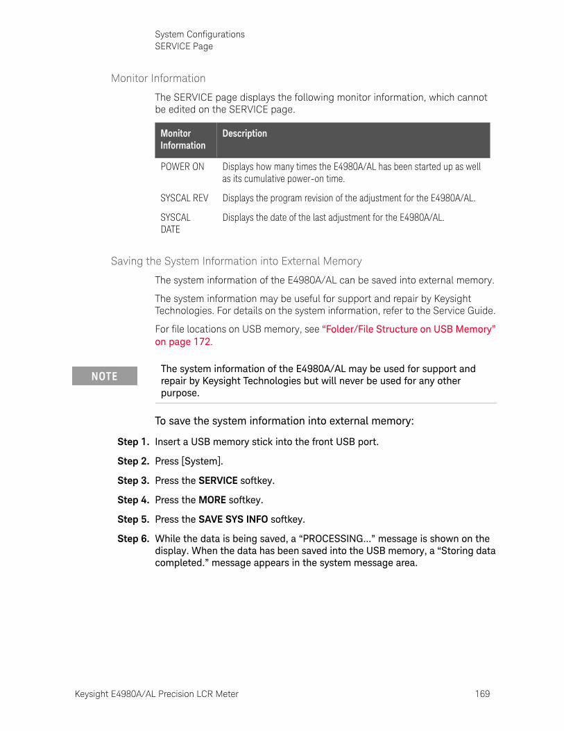
Keysight E4980A/AL Precision LCR Meter 169
System ConfigurationsSERVICE Page
Monitor Information
The SERVICE page displays the following monitor information, which cannot be edited on the SERVICE page.
Saving the System Information into External Memory
The system information of the E4980A/AL can be saved into external memory.
The system information may be useful for support and repair by Keysight Technologies. For details on the system information, refer to the Service Guide.
For file locations on USB memory, see “Folder/File Structure on USB Memory” on page 172.
To save the system information into external memory:
Step 1. Insert a USB memory stick into the front USB port.
Step 2. Press [System].
Step 3. Press the SERVICE softkey.
Step 4. Press the MORE softkey.
Step 5. Press the SAVE SYS INFO softkey.
Step 6. While the data is being saved, a “PROCESSING...” message is shown on the display. When the data has been saved into the USB memory, a “Storing data completed.” message appears in the system message area.
Monitor Information
Description
POWER ON Displays how many times the E4980A/AL has been started up as well as its cumulative power-on time.
SYSCAL REV Displays the program revision of the adjustment for the E4980A/AL.
SYSCAL DATE
Displays the date of the last adjustment for the E4980A/AL.
The system information of the E4980A/AL may be used for support and repair by Keysight Technologies but will never be used for any other purpose.

170 Keysight E4980A/AL Precision LCR Meter
System ConfigurationsSERVICE Page
5-
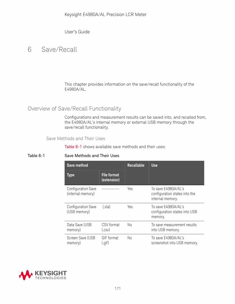
171
Keysight E4980A/AL Precision LCR Meter
User’s Guide
6 Save/Recall
This chapter provides information on the save/recall functionality of the E4980A/AL.
Overview of Save/Recall FunctionalityConfigurations and measurement results can be saved into, and recalled from, the E4980A/AL’s internal memory or external USB memory through the save/recall functionality.
Save Methods and Their Uses
Table 6-1 shows available save methods and their uses:
Table 6-1 Save Methods and Their Uses
Save method Recallable Use
Type File format (extension)
Configuration Save (internal memory)
----------- Yes To save E4980A/AL’s configuration states into the internal memory.
Configuration Save (USB memory)
(.sta) Yes To save E4980A/AL’s configuration states into USB memory.
Data Save (USB memory)
CSV format (.csv)
No To save measurement results into USB memory.
Screen Save (USB memory)
GIF format (.gif )
No To save E4980A/AL’s screenshot into USB memory.
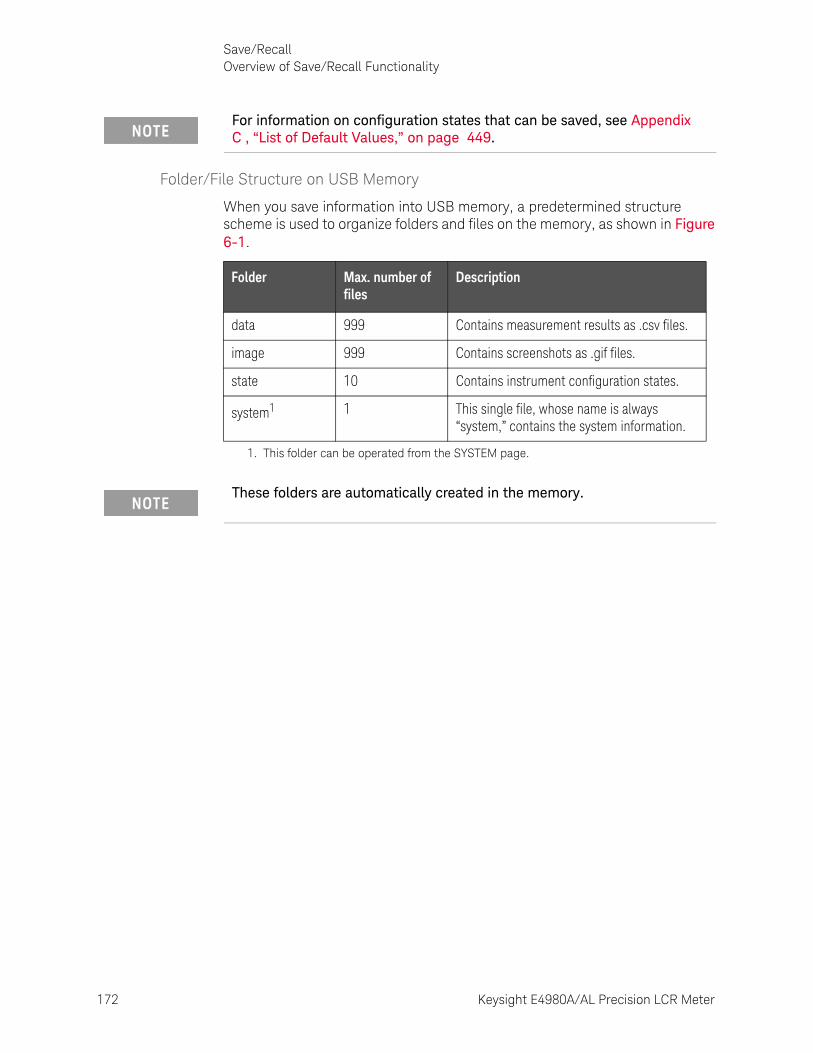
172 Keysight E4980A/AL Precision LCR Meter
Save/RecallOverview of Save/Recall Functionality
6-
Folder/File Structure on USB Memory
When you save information into USB memory, a predetermined structure scheme is used to organize folders and files on the memory, as shown in Figure 6-1.
For information on configuration states that can be saved, see Appendix C , “List of Default Values,” on page 449.
Folder Max. number of files
Description
data 999 Contains measurement results as .csv files.
image 999 Contains screenshots as .gif files.
state 10 Contains instrument configuration states.
system1
1. This folder can be operated from the SYSTEM page.
1 This single file, whose name is always “system,” contains the system information.
These folders are automatically created in the memory.
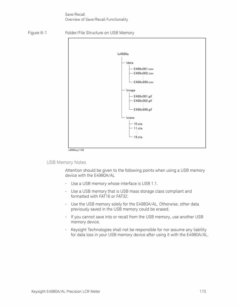
Keysight E4980A/AL Precision LCR Meter 173
Save/RecallOverview of Save/Recall Functionality
Figure 6-1 Folder/File Structure on USB Memory
USB Memory Notes
Attention should be given to the following points when using a USB memory device with the E4980A/AL
• Use a USB memory whose interface is USB 1.1.
• Use a USB memory that is USB mass storage class compliant and formatted with FAT16 or FAT32.
• Use the USB memory solely for the E4980A/AL. Otherwise, other data previously saved in the USB memory could be erased.
• If you cannot save into or recall from the USB memory, use another USB memory device.
• Keysight Technologies shall not be responsible for nor assume any liability for data loss in your USB memory device after using it with the E4980A/AL.
\
\
\
\
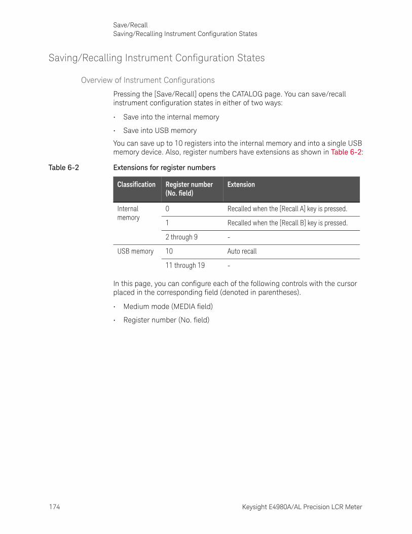
174 Keysight E4980A/AL Precision LCR Meter
Save/RecallSaving/Recalling Instrument Configuration States
6-
Saving/Recalling Instrument Configuration States
Overview of Instrument Configurations
Pressing the [Save/Recall] opens the CATALOG page. You can save/recall instrument configuration states in either of two ways:
• Save into the internal memory
• Save into USB memory
You can save up to 10 registers into the internal memory and into a single USB memory device. Also, register numbers have extensions as shown in Table 6-2:
In this page, you can configure each of the following controls with the cursor placed in the corresponding field (denoted in parentheses).
• Medium mode (MEDIA field)
• Register number (No. field)
Table 6-2 Extensions for register numbers
Classification Register number (No. field)
Extension
Internal memory
0 Recalled when the [Recall A] key is pressed.
1 Recalled when the [Recall B] key is pressed.
2 through 9 -
USB memory 10 Auto recall
11 through 19 -

Keysight E4980A/AL Precision LCR Meter 175
Save/RecallSaving/Recalling Instrument Configuration States
Figure 6-2 CATALOG page
Medium Mode
Functional Description
You have to specify the medium type of the destination or source before saving or recalling instrument configurations.
To select the medium mode:
Step 1. Press [Save/Recall].
Step 2. Use the cursor keys to select the MEDIA field.
Step 3. Select the medium mode by pressing the appropriate softkey:
Softkey Description
INT Uses the internal memory as the destination or source. Once you have selected this mode, the register numbers (in the No. field) change to 0 through 9.
EXT Uses USB memory as the destination or source. Once you have selected this mode, the register numbers (in the No. field) change to 10 through 19.
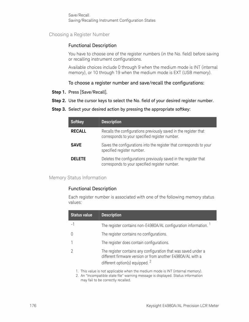
176 Keysight E4980A/AL Precision LCR Meter
Save/RecallSaving/Recalling Instrument Configuration States
6-
Choosing a Register Number
Functional Description
You have to choose one of the register numbers (in the No. field) before saving or recalling instrument configurations.
Available choices include 0 through 9 when the medium mode is INT (internal memory), or 10 through 19 when the medium mode is EXT (USB memory).
To choose a register number and save/recall the configurations:
Step 1. Press [Save/Recall].
Step 2. Use the cursor keys to select the No. field of your desired register number.
Step 3. Select your desired action by pressing the appropriate softkey:
Memory Status Information
Functional Description
Each register number is associated with one of the following memory status values:
Softkey Description
RECALL Recalls the configurations previously saved in the register that corresponds to your specified register number.
SAVE Saves the configurations into the register that corresponds to your specified register number.
DELETE Deletes the configurations previously saved in the register that corresponds to your specified register number.
Status value Description
-1 The register contains non-E4980A/AL configuration information. 1
0 The register contains no configurations.
1 The register does contain configurations.
2 The register contains any configuration that was saved under a different firmware version or from another E4980A/AL with a different option(s) equipped. 2
1. This value is not applicable when the medium mode is INT (internal memory). 2. An “Incompatible state file” warning message is displayed. Status information
may fail to be correctly recalled.
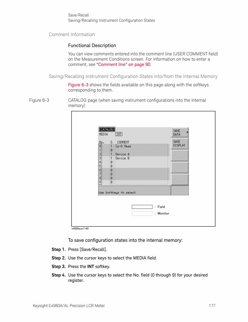
Keysight E4980A/AL Precision LCR Meter 177
Save/RecallSaving/Recalling Instrument Configuration States
Comment Information
Functional Description
You can view comments entered into the comment line (USER COMMENT field) on the Measurement Conditions screen. For information on how to enter a comment, see “Comment line” on page 90.
Saving/Recalling Instrument Configuration States into/from the Internal Memory
Figure 6-3 shows the fields available on this page along with the softkeys corresponding to them.
Figure 6-3 CATALOG page (when saving instrument configurations into the internal memory)
To save configuration states into the internal memory:
Step 1. Press [Save/Recall].
Step 2. Use the cursor keys to select the MEDIA field.
Step 3. Press the INT softkey.
Step 4. Use the cursor keys to select the No. field (0 through 9) for your desired register.
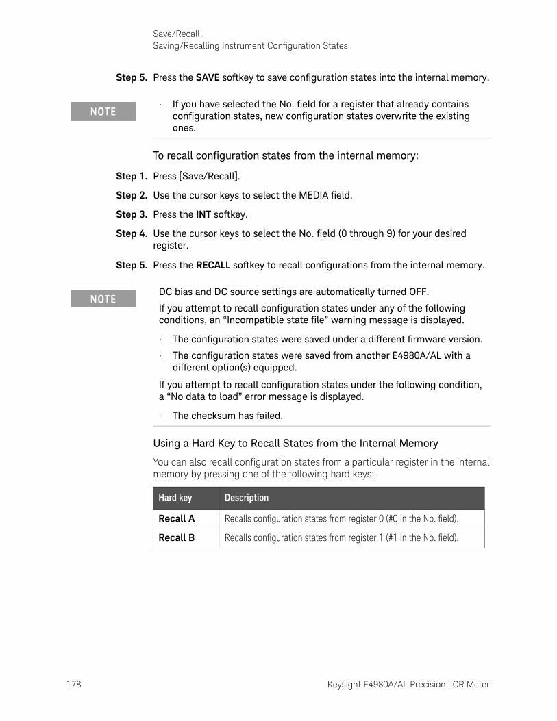
178 Keysight E4980A/AL Precision LCR Meter
Save/RecallSaving/Recalling Instrument Configuration States
6-
Step 5. Press the SAVE softkey to save configuration states into the internal memory.
To recall configuration states from the internal memory:
Step 1. Press [Save/Recall].
Step 2. Use the cursor keys to select the MEDIA field.
Step 3. Press the INT softkey.
Step 4. Use the cursor keys to select the No. field (0 through 9) for your desired register.
Step 5. Press the RECALL softkey to recall configurations from the internal memory.
Using a Hard Key to Recall States from the Internal Memory
You can also recall configuration states from a particular register in the internal memory by pressing one of the following hard keys:
• If you have selected the No. field for a register that already contains configuration states, new configuration states overwrite the existing ones.
DC bias and DC source settings are automatically turned OFF.
If you attempt to recall configuration states under any of the following conditions, an “Incompatible state file” warning message is displayed.
• The configuration states were saved under a different firmware version.
• The configuration states were saved from another E4980A/AL with a different option(s) equipped.
If you attempt to recall configuration states under the following condition, a “No data to load” error message is displayed.
• The checksum has failed.
Hard key Description
Recall A Recalls configuration states from register 0 (#0 in the No. field).
Recall B Recalls configuration states from register 1 (#1 in the No. field).
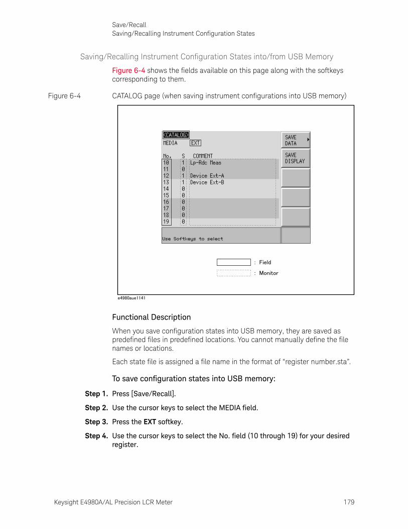
Keysight E4980A/AL Precision LCR Meter 179
Save/RecallSaving/Recalling Instrument Configuration States
Saving/Recalling Instrument Configuration States into/from USB Memory
Figure 6-4 shows the fields available on this page along with the softkeys corresponding to them.
Figure 6-4 CATALOG page (when saving instrument configurations into USB memory)
Functional Description
When you save configuration states into USB memory, they are saved as predefined files in predefined locations. You cannot manually define the file names or locations.
Each state file is assigned a file name in the format of “register number.sta”.
To save configuration states into USB memory:
Step 1. Press [Save/Recall].
Step 2. Use the cursor keys to select the MEDIA field.
Step 3. Press the EXT softkey.
Step 4. Use the cursor keys to select the No. field (10 through 19) for your desired register.
180 Keysight E4980A/AL Precision LCR Meter
Save/RecallSaving/Recalling Instrument Configuration States
6-
Step 5. Press the SAVE softkey to save configuration states into the USB memory.
To recall configuration states from USB memory:
Step 1. Press [Save/Recall].
Step 2. Use the cursor keys to select the MEDIA field.
Step 3. Press the EXT softkey.
Step 4. Use the cursor keys to select the No. field (10 through 19) for your desired register.
Step 5. Press the RECALL softkey to recall configurations from the USB memory.
If you attempt to recall configuration states under any of the following conditions, an “Incompatible state file” warning message is displayed.
• The configuration states were saved under a different firmware version.
• The configuration states were saved from another E4980A/AL with a different option(s) equipped.
If you attempt to recall configuration states under the following condition, a “No data to load” error message is displayed.
• The checksum has changed.
If you have selected the No. field for a register that already contains configuration states, the new configuration states overwrite the existing ones.
State files are automatically assigned file names 10.sta through 19.sta, and you cannot change the file names.
DC bias and DC source settings are automatically turned OFF.

Keysight E4980A/AL Precision LCR Meter 181
Save/RecallSaving/Recalling Instrument Configuration States
Using the Auto Recall Feature
Functional Description
You can have the E4980A/AL, at start-up time, automatically recall the configuration states previously saved in register number 10 on USB memory. To use this feature, you have to plug the appropriate USB memory into the E4980A/AL before starting up.
To use the auto recall feature:
Step 1. Plug the appropriate USB memory into the E4980A/AL.
Step 2. Turn on the power to the E4980A/AL.
Step 3. Upon start-up, the instrument configures itself using the instrument configuration information previously saved in register number 10 on the USB memory device.
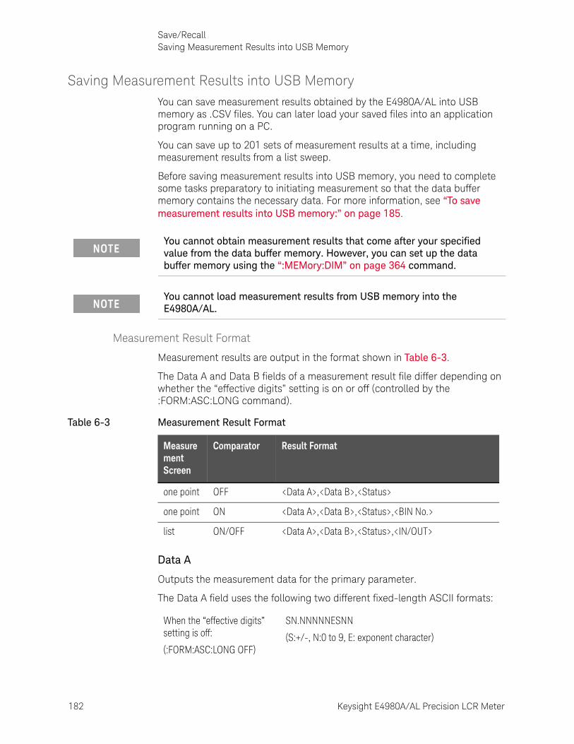
182 Keysight E4980A/AL Precision LCR Meter
Save/RecallSaving Measurement Results into USB Memory
6-
Saving Measurement Results into USB MemoryYou can save measurement results obtained by the E4980A/AL into USB memory as .CSV files. You can later load your saved files into an application program running on a PC.
You can save up to 201 sets of measurement results at a time, including measurement results from a list sweep.
Before saving measurement results into USB memory, you need to complete some tasks preparatory to initiating measurement so that the data buffer memory contains the necessary data. For more information, see “To save measurement results into USB memory:” on page 185.
Measurement Result Format
Measurement results are output in the format shown in Table 6-3.
The Data A and Data B fields of a measurement result file differ depending on whether the “effective digits” setting is on or off (controlled by the :FORM:ASC:LONG command).
Data A
Outputs the measurement data for the primary parameter.
The Data A field uses the following two different fixed-length ASCII formats:
You cannot obtain measurement results that come after your specified value from the data buffer memory. However, you can set up the data buffer memory using the “:MEMory:DIM” on page 364 command.
You cannot load measurement results from USB memory into the E4980A/AL.
Table 6-3 Measurement Result Format
Measurement Screen
Comparator Result Format
one point OFF <Data A>,<Data B>,<Status>
one point ON <Data A>,<Data B>,<Status>,<BIN No.>
list ON/OFF <Data A>,<Data B>,<Status>,<IN/OUT>
When the “effective digits” setting is off:
(:FORM:ASC:LONG OFF)
SN.NNNNNESNN
(S:+/-, N:0 to 9, E: exponent character)
Keysight E4980A/AL Precision LCR Meter 183
Save/RecallSaving Measurement Results into USB Memory
Data B
Outputs the measurement data for the secondary parameter.
The Data B field uses the following two different fixed-length ASCII formats:
Status
Represents the measurement result status by using one of the following status values:
The Status field uses the following two-character fixed-length ASCII format:
SN (S:+/-, N:0 to 4)
Bin No. (IN/OUT)
Represents the bin sorting results as well as IN/OUT evaluation results in list sweep measurement, as shown below:
When the “effective digits” setting is on:
(:FORM:ASC:LONG ON)
SN.NNNNNNNNNESNN
(S:+/-, N:0 to 9, E: exponent character)
When the “effective digits” setting is off:
:FORM:ASC:LONG OFF
SN.NNNNNESNN
(S:+/-, N:0 to 9, E: exponent character)
When the “effective digits” setting is on:
:FORM:ASC:LONG ON
SN.NNNNNNNNNESNN
(S:+/-, N:0 to 9, E: exponent character)
0 Measurement successfully completed.
+1 Overload.
+3 A signal is detected exceeding the allowable limit of the signal source.
+4 The automatic level control (ALC) feature does not work.
If the value is 1, the measurement data is 9.9E37; if the value is 0, 3, or 4, the actual measurement data is output.
The data buffer memory contains a measurement result with no data (as represented by the status value of -1), but it is excluded when the data is saved into USB memory.
0 OUT_OF_BINS
+1 to +9 BIN 1 through BIN 9
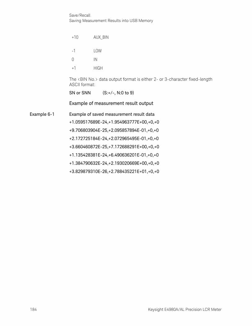
184 Keysight E4980A/AL Precision LCR Meter
Save/RecallSaving Measurement Results into USB Memory
6-
The <BIN No.> data output format is either 2- or 3-character fixed-length ASCII format:
SN or SNN (S:+/-, N:0 to 9)
Example of measurement result output
Example 6-1 Example of saved measurement result data
+1.059517689E-24,+1.954963777E+00,+0,+0
+9.706803904E-25,+2.095857894E-01,+0,+0
+2.172725184E-24,+2.072965495E-01,+0,+0
+3.660460872E-25,+7.172688291E+00,+0,+0
+1.135428381E-24,+6.490636201E-01,+0,+0
+1.384790632E-24,+2.193020669E+00,+0,+0
+3.829879310E-26,+2.788435221E+01,+0,+0
+10 AUX_BIN
-1 LOW
0 IN
+1 HIGH
Keysight E4980A/AL Precision LCR Meter 185
Save/RecallSaving Measurement Results into USB Memory
To save measurement results into USB memory:
For how to save the measurement result, refer to “How to save the measurement result of List Sweep Measurement to USB memory.” on page 186.
Step 1. Plug a USB memory stick into the front USB port.
Step 2. Press [Save/Recall].
Step 3. Press the SAVE DATA softkey.
Step 4. Press the START LOG softkey and then press the following softkeys to enter the measurement results into the data buffer memory.
Step 5. Start measurement. The data buffer memory is filled with up to 201 sets of measurement results.
Step 6. Press the SAVE & STOP softkey to save results into the USB memory.
Step 7. When the data has been saved into the USB memory, a “Storing data completed. : E498xXXX.csv” message appears in the system message area.
Softkey Description
START LOG Starts logging the measurement results into the data buffer memory.
SAVE & STOP
Copies the data from the data buffer memory into the USB memory. Then stops saving the measurement results into the data buffer memory and clears the data buffer memory.
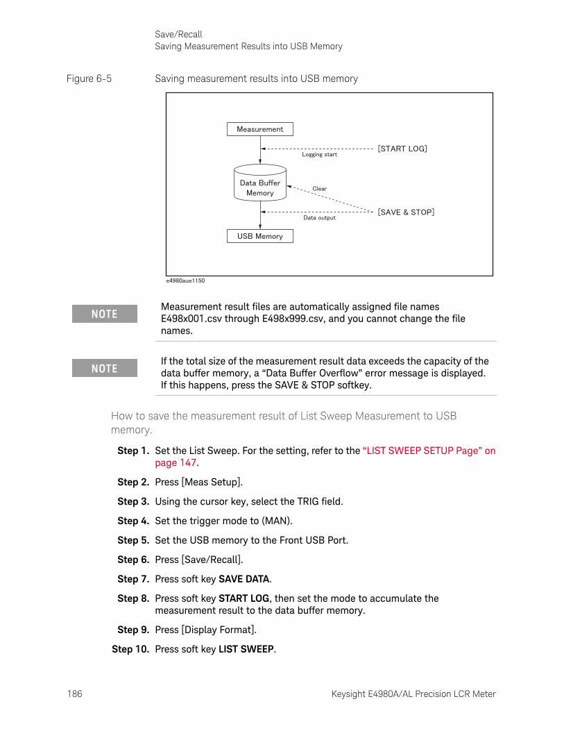
186 Keysight E4980A/AL Precision LCR Meter
Save/RecallSaving Measurement Results into USB Memory
6-
Figure 6-5 Saving measurement results into USB memory
How to save the measurement result of List Sweep Measurement to USB memory.
Step 1. Set the List Sweep. For the setting, refer to the “LIST SWEEP SETUP Page” on page 147.
Step 2. Press [Meas Setup].
Step 3. Using the cursor key, select the TRIG field.
Step 4. Set the trigger mode to (MAN).
Step 5. Set the USB memory to the Front USB Port.
Step 6. Press [Save/Recall].
Step 7. Press soft key SAVE DATA.
Step 8. Press soft key START LOG, then set the mode to accumulate the measurement result to the data buffer memory.
Step 9. Press [Display Format].
Step 10. Press soft key LIST SWEEP.
Measurement result files are automatically assigned file names E498x001.csv through E498x999.csv, and you cannot change the file names.
If the total size of the measurement result data exceeds the capacity of the data buffer memory, a “Data Buffer Overflow” error message is displayed. If this happens, press the SAVE & STOP softkey.
Keysight E4980A/AL Precision LCR Meter 187
Save/RecallSaving Measurement Results into USB Memory
Step 11. Press [Trigger], then measure once.
Step 12. Press [Save/Recall].
Step 13. Press soft key SAVE DATA.
Step 14. Press soft key SAVE & STOP, then save to USB memory.
Step 15. When you complete the saving at USB memory, the message “Storing data completed. : E498xXXX.csv” appears at system message area.
For example, when measurement point of List Sweep is 100, 100 measurement results are saved to USB memory.
Measurement result files are automatically assigned file names E498x001.csv through E498x999.csv, and you cannot change the file names.

188 Keysight E4980A/AL Precision LCR Meter
Save/RecallSaving a Screenshot into USB Memory
6-
Saving a Screenshot into USB MemoryYou can save a screenshot of the E4980A/AL’s display into USB memory as a .GIF file. You can later load your saved file into an application program running on a PC.
To save a screenshot into USB memory
Step 1. Display the screen you want to save.
Step 2. Plug a USB memory device into the front USB port.
Step 3. Press [Save/Recall].
Step 4. Press the SAVE DISPLAY softkey.
Step 5. When the data has been saved into the USB memory device, a “Storing image completed. : E498xXXX.gif” message appears in the system message area.
Screenshot files are automatically assigned file names E498x001.gif through E498x999.gif, and you cannot change the file names.
189
Keysight E4980A/AL Precision LCR Meter
User’s Guide
7 Measurement Procedure and Examples
This chapter covers basic measurement procedures as well as basic L, C, and R measurement theory. It also offers various measurement hints. After the descriptions of basic measurement procedures, practical measurement examples are shown using the E4980A/AL.
Basic Measurement ProcedureThe following flow chart shows the basic procedures used to measure the impedance of capacitors, inductors, resistors, and other components. Follow the procedures to perform impedance measurements while referring to the items noted to the right side of each step.
For basic measurements, refer to the Impedance Measurement Handbook. For the fixtures that can be used, refer to the Accessories Selection Guide For Impedance Measurements.These documents can be downloaded from this URL:
http://www.keysight.com/find/lcrmeters/
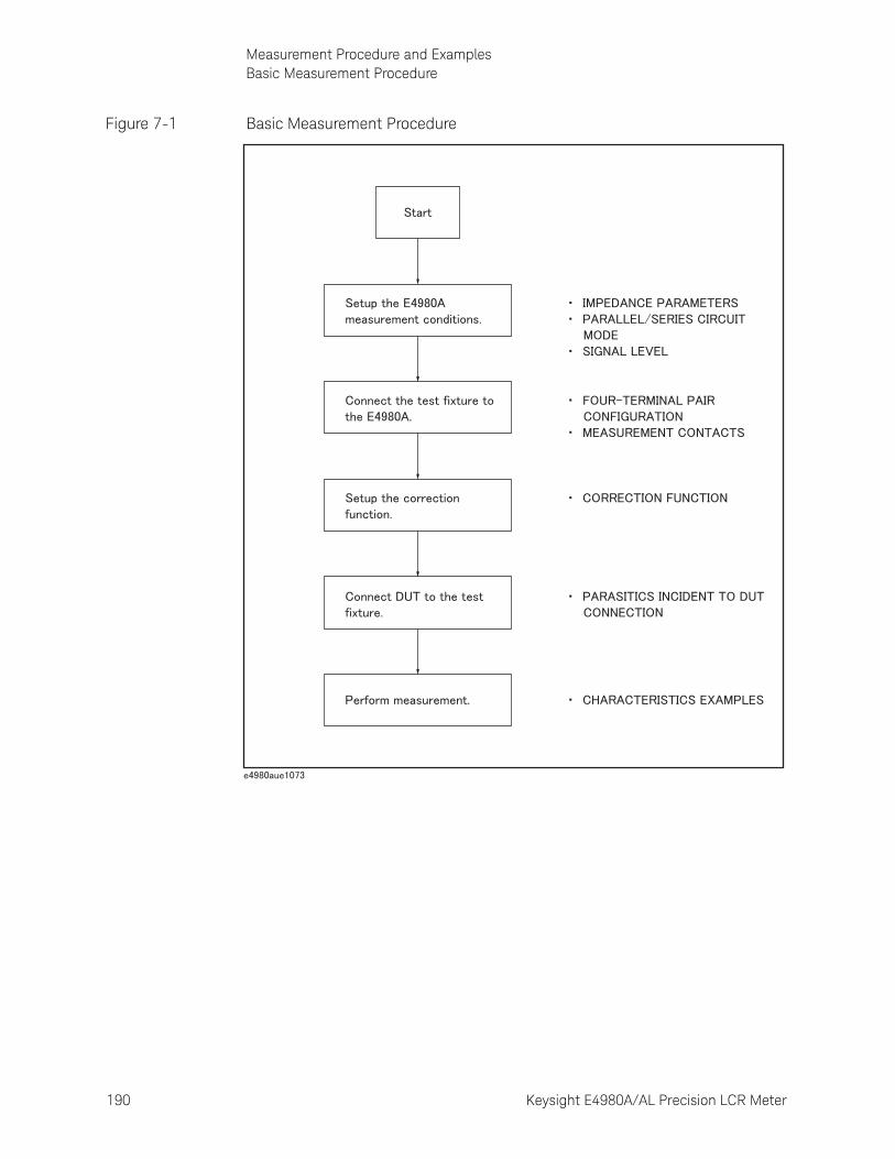
190 Keysight E4980A/AL Precision LCR Meter
Measurement Procedure and ExamplesBasic Measurement Procedure
7-
Figure 7-1 Basic Measurement Procedure
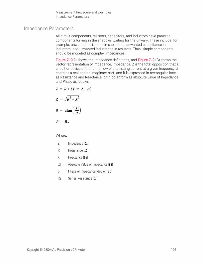
Keysight E4980A/AL Precision LCR Meter 191
Measurement Procedure and ExamplesImpedance Parameters
Impedance ParametersAll circuit components, resistors, capacitors, and inductors have parasitic components lurking in the shadows waiting for the unwary. These include, for example, unwanted resistance in capacitors, unwanted capacitance in inductors, and unwanted inductance in resistors. Thus, simple components should be modeled as complex impedances.
Figure 7-2(A) shows the impedance definitions, and Figure 7-2 (B) shows the vector representation of impedance. Impedance, Z is the total opposition that a circuit or device offers to the flow of alternating current at a given frequency. Z contains a real and an imaginary part, and it is expressed in rectangular form as Resistance and Reactance, or in polar form as absolute value of Impedance and Phase as follows.
Where,
Z Impedance []
R Resistance []
X Reactance []
|Z| Absolute Value of Impedance []
Phase of Impedance [deg or rad]
Rs Series Resistance []
Z R jX+ Z = =
Z R2
X2
+=
XR------ atan=
R Rs=
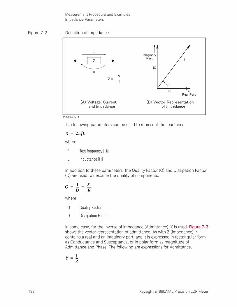
192 Keysight E4980A/AL Precision LCR Meter
Measurement Procedure and ExamplesImpedance Parameters
7-
Figure 7-2 Definition of Impedance
The following parameters can be used to represent the reactance.
where
In addition to these parameters, the Quality Factor (Q) and Dissipation Factor (D) are used to describe the quality of components.
where
In some case, for the inverse of impedance (Admittance), Y is used. Figure 7-3 shows the vector representation of admittance. As with Z (Impedance), Y contains a real and an imaginary part, and it is expressed in rectangular form as Conductance and Susceptance, or in polar form as magnitude of Admittance and Phase. The following are expressions for Admittance.
f Test frequency [Hz]
L Inductance [H]
Q Quality Factor
D Dissipation Factor
X 2fL=
Q 1D---- X
R------= =
Y 1Z---=
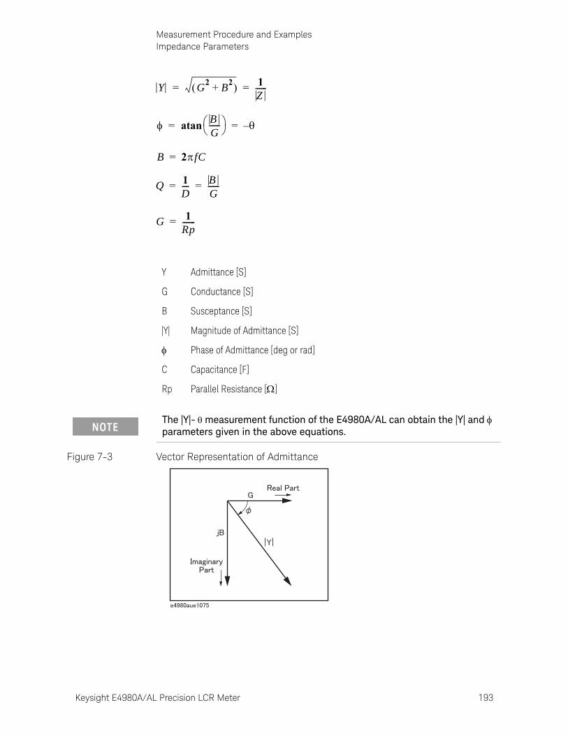
Keysight E4980A/AL Precision LCR Meter 193
Measurement Procedure and ExamplesImpedance Parameters
Figure 7-3 Vector Representation of Admittance
Y Admittance [S]
G Conductance [S]
B Susceptance [S]
|Y| Magnitude of Admittance [S]
Phase of Admittance [deg or rad]
C Capacitance [F]
Rp Parallel Resistance []
Y G2
B2
+ 1Z------= =
BG------ atan –= =
B 2fC=
Q 1D---- B
G------= =
G 1Rp-------=
The |Y|- measurement function of the E4980A/AL can obtain the |Y| and parameters given in the above equations.

194 Keysight E4980A/AL Precision LCR Meter
Measurement Procedure and ExamplesParallel/Series Circuit Mode
7-
Parallel/Series Circuit ModeTo measure L, C, or R, there are two equivalent circuit modes: the parallel and series modes as shown in Table 7-1. The E4980A/AL can select the mode by setting the FUNC (Cp, Cs, Lp, or Ls) on the MEAS SETUP page. To determine which mode is better, consider the relative impedance magnitude of the reactance and Rs and Rp.
Table 7-1 Parallel/Series Circuit Mode
Circuit Mode Measurement Function Definition of D, Q, and G
Cp mode Cp-D
Cp-Q
Cp-G
Cp-Rp
Cs mode Cs-D
Cs-Q
Cs-Rs
Lp mode Lp-D
Lp-Q
Lp-G
Lp-Rp
Ls mode Ls-D
Ls-Q
Ls-Rs
Cp
Rp
D 12fCpRp----------------------- 1
Q----= =
G 1Rp-------=
Cs Rs
D 2fCsRs 1Q----= =
Lp
Rp
Q Rp2fLp--------------- 1
D----= =
G 1Rp-------=
Ls Rs
Q 2fLsRs
--------------- 1D----= =
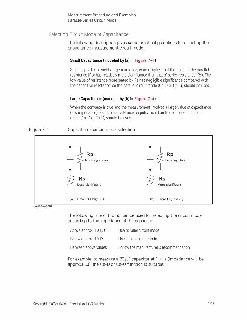
Keysight E4980A/AL Precision LCR Meter 195
Measurement Procedure and ExamplesParallel/Series Circuit Mode
Selecting Circuit Mode of Capacitance
The following description gives some practical guidelines for selecting the capacitance measurement circuit mode.
Figure 7-4 Capacitance circuit mode selection
The following rule of thumb can be used for selecting the circuit mode according to the impedance of the capacitor.
For example, to measure a 20 F capacitor at 1 kHz (impedance will be approx.8 ), the Cs-D or Cs-Q function is suitable.
Small Capacitance (modeled by (a) in Figure 7-4)
Small capacitance yields large reactance, which implies that the effect of the parallel resistance (Rp) has relatively more significance than that of series resistance (Rs). The low value of resistance represented by Rs has negligible significance compared with the capacitive reactance, so the parallel circuit mode (Cp-D or Cp-G) should be used.
Large Capacitance (modeled by (b) in Figure 7-4)
When the converse is true and the measurement involves a large value of capacitance (low impedance), Rs has relatively more significance than Rp, so the series circuit mode (Cs-D or Cs-Q) should be used.
Rs
Rp
Rs
Rp
Above approx. 10 k Use parallel circuit mode
Below approx. 10 Use series circuit mode
Between above values Follow the manufacturer’s recommendation
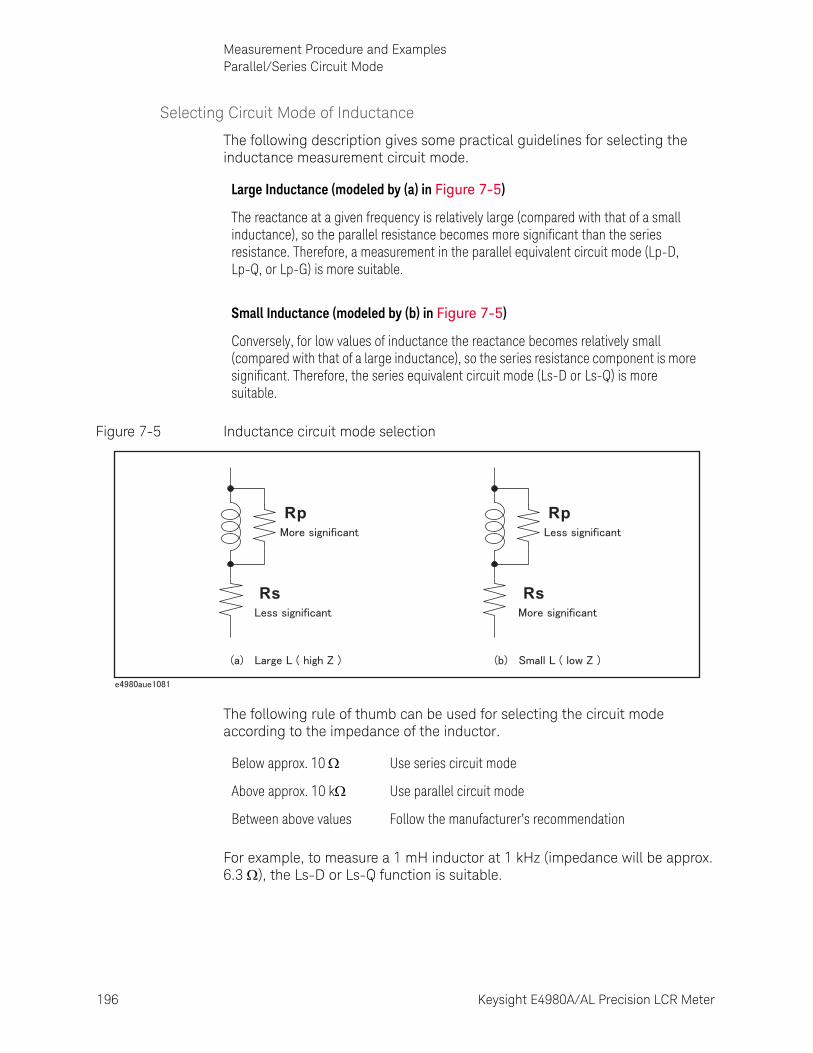
196 Keysight E4980A/AL Precision LCR Meter
Measurement Procedure and ExamplesParallel/Series Circuit Mode
7-
Selecting Circuit Mode of Inductance
The following description gives some practical guidelines for selecting the inductance measurement circuit mode.
Figure 7-5 Inductance circuit mode selection
The following rule of thumb can be used for selecting the circuit mode according to the impedance of the inductor.
For example, to measure a 1 mH inductor at 1 kHz (impedance will be approx. 6.3 ), the Ls-D or Ls-Q function is suitable.
Large Inductance (modeled by (a) in Figure 7-5)
The reactance at a given frequency is relatively large (compared with that of a small inductance), so the parallel resistance becomes more significant than the series resistance. Therefore, a measurement in the parallel equivalent circuit mode (Lp-D, Lp-Q, or Lp-G) is more suitable.
Small Inductance (modeled by (b) in Figure 7-5)
Conversely, for low values of inductance the reactance becomes relatively small (compared with that of a large inductance), so the series resistance component is more significant. Therefore, the series equivalent circuit mode (Ls-D or Ls-Q) is more suitable.
Rs
Rp
Rs
Rp
Below approx. 10 Use series circuit mode
Above approx. 10 k Use parallel circuit mode
Between above values Follow the manufacturer’s recommendation
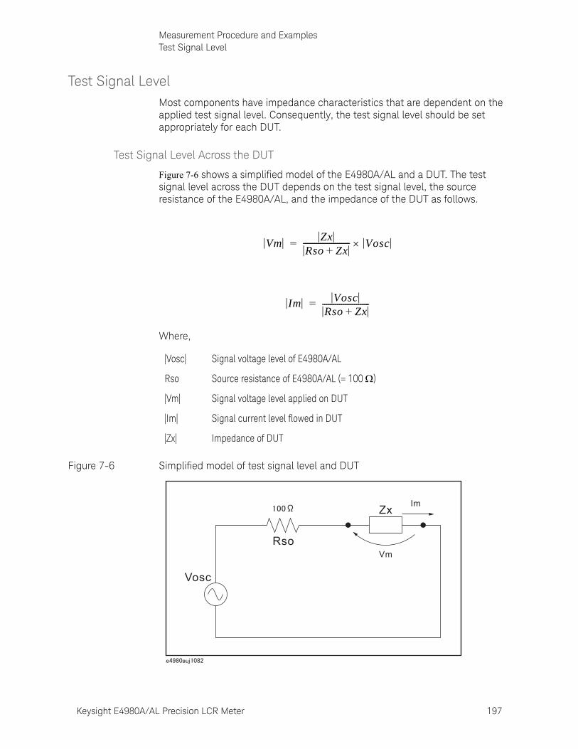
Keysight E4980A/AL Precision LCR Meter 197
Measurement Procedure and ExamplesTest Signal Level
Test Signal LevelMost components have impedance characteristics that are dependent on the applied test signal level. Consequently, the test signal level should be set appropriately for each DUT.
Test Signal Level Across the DUT
Figure 7-6 shows a simplified model of the E4980A/AL and a DUT. The test signal level across the DUT depends on the test signal level, the source resistance of the E4980A/AL, and the impedance of the DUT as follows.
Where,
Figure 7-6 Simplified model of test signal level and DUT
|Vosc| Signal voltage level of E4980A/AL
Rso Source resistance of E4980A/AL (= 100 )
|Vm| Signal voltage level applied on DUT
|Im| Signal current level flowed in DUT
|Zx| Impedance of DUT
VmZx
Rso Zx+------------------------- Vosc=
Im VoscRso Zx+-------------------------=
Zx
Vm
Im
Rso
Vosc
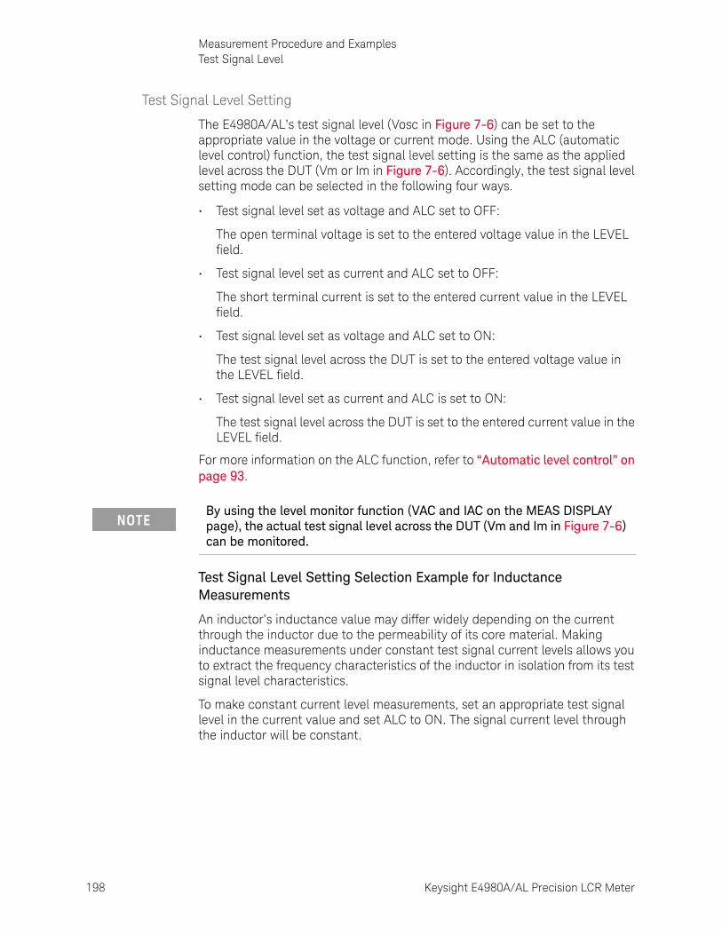
198 Keysight E4980A/AL Precision LCR Meter
Measurement Procedure and ExamplesTest Signal Level
7-
Test Signal Level Setting
The E4980A/AL’s test signal level (Vosc in Figure 7-6) can be set to the appropriate value in the voltage or current mode. Using the ALC (automatic level control) function, the test signal level setting is the same as the applied level across the DUT (Vm or Im in Figure 7-6). Accordingly, the test signal level setting mode can be selected in the following four ways.
• Test signal level set as voltage and ALC set to OFF:
The open terminal voltage is set to the entered voltage value in the LEVEL field.
• Test signal level set as current and ALC set to OFF:
The short terminal current is set to the entered current value in the LEVEL field.
• Test signal level set as voltage and ALC set to ON:
The test signal level across the DUT is set to the entered voltage value in the LEVEL field.
• Test signal level set as current and ALC is set to ON:
The test signal level across the DUT is set to the entered current value in the LEVEL field.
For more information on the ALC function, refer to “Automatic level control” on page 93.
Test Signal Level Setting Selection Example for Inductance Measurements
An inductor’s inductance value may differ widely depending on the current through the inductor due to the permeability of its core material. Making inductance measurements under constant test signal current levels allows you to extract the frequency characteristics of the inductor in isolation from its test signal level characteristics.
To make constant current level measurements, set an appropriate test signal level in the current value and set ALC to ON. The signal current level through the inductor will be constant.
By using the level monitor function (VAC and IAC on the MEAS DISPLAY page), the actual test signal level across the DUT (Vm and Im in Figure 7-6) can be monitored.

Keysight E4980A/AL Precision LCR Meter 199
Measurement Procedure and ExamplesFour-Terminal Pair Configuration
Four-Terminal Pair ConfigurationGenerally, any mutual inductance, interference of the test signals, or unwanted residual factors in the connection method incidental to ordinary termination methods will have a significant effect on measurement, especially at high frequency. The E4980A/AL employs a four-terminal pair measurement configuration that permits easy, stable, and accurate measurement while avoiding the negative influences inherent in the above factors. The 4TP configuration can improve the impedance measurement range to below 1 m
Figure 7-7 shows the four-terminal pair measurement principle. The set of UNKNOWN terminals consists of four coaxial connectors.
• HCUR: High current• HPOT: High potential• LPOT: Low potential• LCUR: Low current
Figure 7-7 Four-terminal pair measurement principle
Figure 7-7 *1 The shielding conductor of Lcur is shunted to the system ground in the E4980A/AL
The four-terminal pair (4TP) configuration solves the effects of mutual coupling between the leads by employing either or both of the following techniques. The E4980A/AL employs the method 2. At frequencies higher than 10kHz, the effects of 1. is also benefited on the E4980A/AL by the balun effects of the coaxial test leads
1. The outer shield conductors work as the return path for the test signal current (they are not grounded). The magnetic fields produced by the inner and outer currents cancel each other because of the opposite directions
LCUR
LPOTHPOT
HCUR
Vx
Vx
Ix
Ix
*1

200 Keysight E4980A/AL Precision LCR Meter
Measurement Procedure and ExamplesFour-Terminal Pair Configuration
7-
and same amount current flow. Hence there is little inductive magnetic field, test leads do not contribute additional errors due to self or mutual inductance between the individual leads.
2. The vector voltmeter measures the differential voltage between the inner and outer conductors. The differential measurement method can minimize the influence of the mutual inductance.
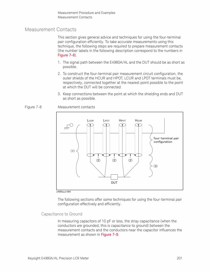
Keysight E4980A/AL Precision LCR Meter 201
Measurement Procedure and ExamplesMeasurement Contacts
Measurement ContactsThis section gives general advice and techniques for using the four-terminal pair configuration efficiently. To take accurate measurements using this technique, the following steps are required to prepare measurement contacts (the number labels in the following description correspond to the numbers in Figure 7-8).
1. The signal path between the E4980A/AL and the DUT should be as short as possible.
2. To construct the four-terminal pair measurement circuit configuration, the outer shields of the HCUR and HPOT, LCUR and LPOT terminals must be, respectively, connected together at the nearest point possible to the point at which the DUT will be connected.
3. Keep connections between the point at which the shielding ends and DUT as short as possible.
Figure 7-8 Measurement contacts
The following sections offer some techniques for using the four-terminal pair configuration effectively and efficiently.
Capacitance to Ground
In measuring capacitors of 10 pF or less, the stray capacitance (when the conductors are grounded, this is capacitance to ground) between the measurement contacts and the conductors near the capacitor influences the measurement as shown in Figure 7-9.
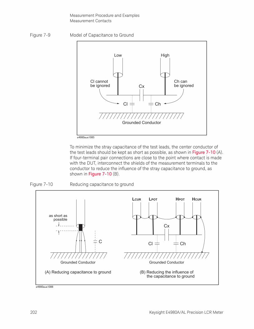
202 Keysight E4980A/AL Precision LCR Meter
Measurement Procedure and ExamplesMeasurement Contacts
7-
Figure 7-9 Model of Capacitance to Ground
To minimize the stray capacitance of the test leads, the center conductor of the test leads should be kept as short as possible, as shown in Figure 7-10 (A). If four-terminal pair connections are close to the point where contact is made with the DUT, interconnect the shields of the measurement terminals to the conductor to reduce the influence of the stray capacitance to ground, as shown in Figure 7-10 (B).
Figure 7-10 Reducing capacitance to ground
Low
Cl cannotbe ignored
High
Ch canbe ignoredCx
Cl Ch
Grounded Conductor
LPOTLCUR HCURHPOT
Cx
Cl Ch
Grounded Conductor
(B) Reducing the influence of the capacitance to ground
Grounded Conductor
(A) Reducing capacitance to ground
C
as short aspossible
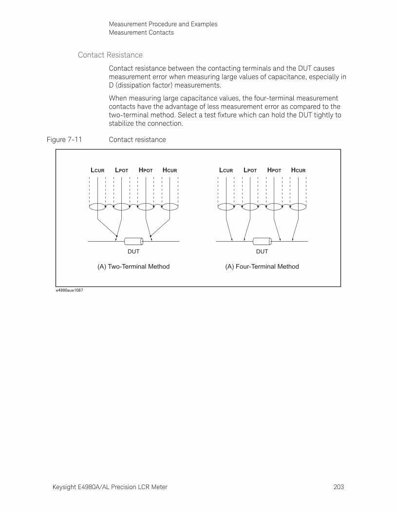
Keysight E4980A/AL Precision LCR Meter 203
Measurement Procedure and ExamplesMeasurement Contacts
Contact Resistance
Contact resistance between the contacting terminals and the DUT causes measurement error when measuring large values of capacitance, especially in D (dissipation factor) measurements.
When measuring large capacitance values, the four-terminal measurement contacts have the advantage of less measurement error as compared to the two-terminal method. Select a test fixture which can hold the DUT tightly to stabilize the connection.
Figure 7-11 Contact resistance
DUT
LCUR LPOT HPOT HCUR
(A) Two-Terminal Method
DUT
LCUR LPOT HPOT HCUR
(A) Four-Terminal Method
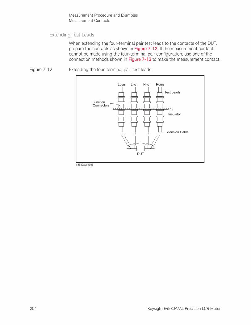
204 Keysight E4980A/AL Precision LCR Meter
Measurement Procedure and ExamplesMeasurement Contacts
7-
Extending Test Leads
When extending the four-terminal pair test leads to the contacts of the DUT, prepare the contacts as shown in Figure 7-12. If the measurement contact cannot be made using the four-terminal pair configuration, use one of the connection methods shown in Figure 7-13 to make the measurement contact.
Figure 7-12 Extending the four-terminal pair test leads
DUT
LCUR LPOT HPOT HCUR
JunctionConnectors
Test Leads
Insulator
Extension Cable
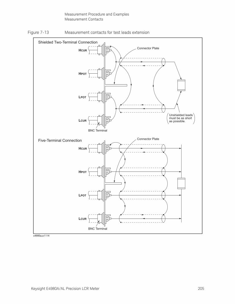
Keysight E4980A/AL Precision LCR Meter 205
Measurement Procedure and ExamplesMeasurement Contacts
Figure 7-13 Measurement contacts for test leads extension
LCUR
LPOT
HPOT
HCUR
Connector Plate
BNC Terminal
LCUR
LPOT
HPOT
HCUR Connector Plate
BNC Terminal
Shielded Two-Terminal Connection
Five-Terminal Connection
Unshielded leadsmust be as shortas possible.
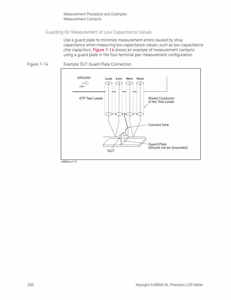
206 Keysight E4980A/AL Precision LCR Meter
Measurement Procedure and ExamplesMeasurement Contacts
7-
Guarding for Measurement of Low Capacitance Values
Use a guard plate to minimize measurement errors caused by stray capacitance when measuring low capacitance values, such as low-capacitance chip capacitors. Figure 7-14 shows an example of measurement contacts using a guard plate in the four-terminal pair measurement configuration.
Figure 7-14 Example DUT Guard Plate Connection
LCUR LPOT HPOT HCUR
4TP Test Leads Shield Conductorof the Test Leads
DUT
GROUND
Connect here
Guard Plate(Should not be Grounded)
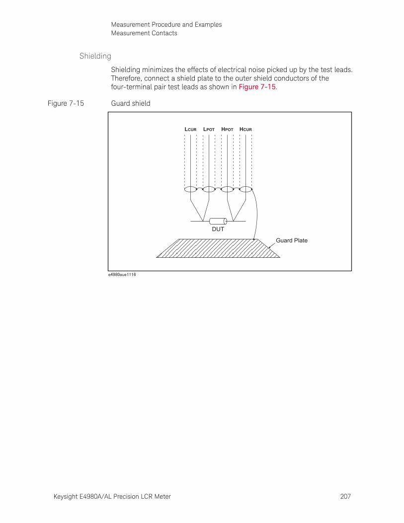
Keysight E4980A/AL Precision LCR Meter 207
Measurement Procedure and ExamplesMeasurement Contacts
Shielding
Shielding minimizes the effects of electrical noise picked up by the test leads. Therefore, connect a shield plate to the outer shield conductors of the four-terminal pair test leads as shown in Figure 7-15.
Figure 7-15 Guard shield
LCUR LPOT HPOT HCUR
DUT
Guard Plate
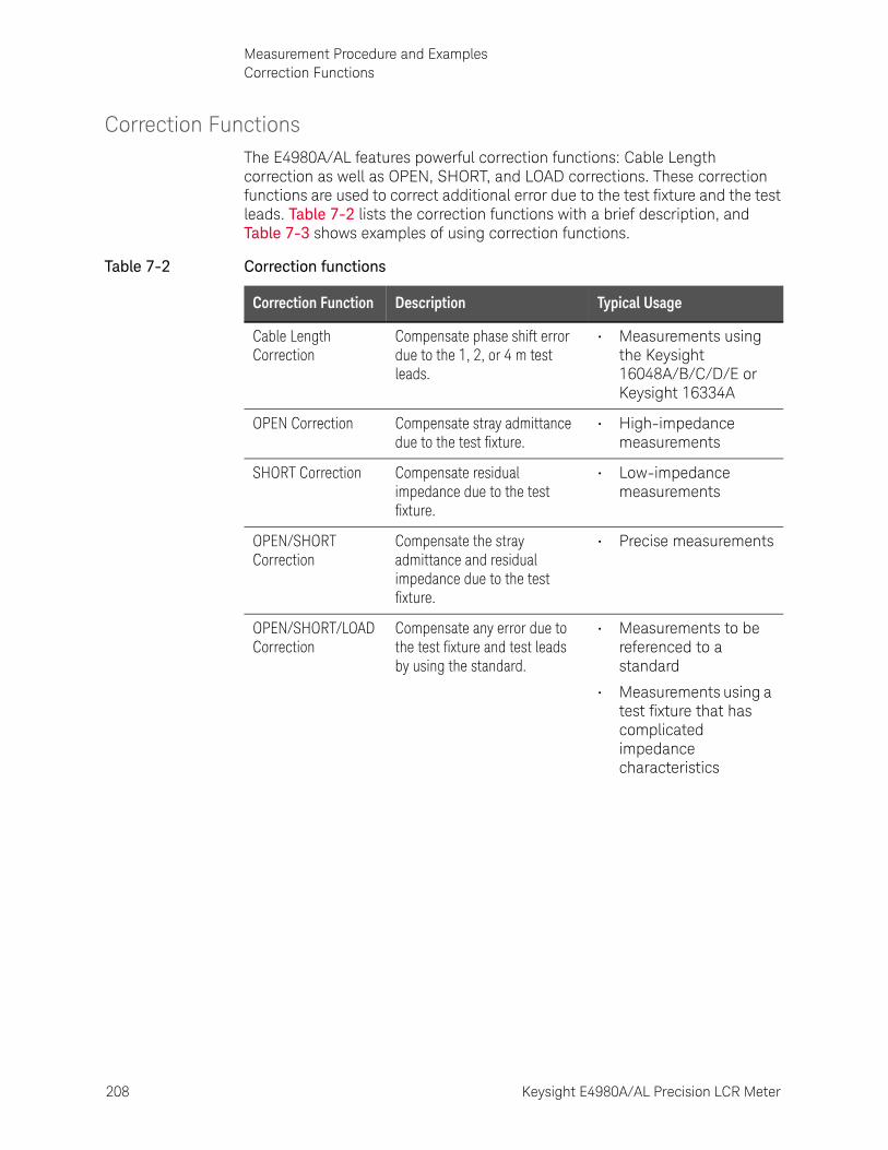
208 Keysight E4980A/AL Precision LCR Meter
Measurement Procedure and ExamplesCorrection Functions
7-
Correction FunctionsThe E4980A/AL features powerful correction functions: Cable Length correction as well as OPEN, SHORT, and LOAD corrections. These correction functions are used to correct additional error due to the test fixture and the test leads. Table 7-2 lists the correction functions with a brief description, and Table 7-3 shows examples of using correction functions.
Table 7-2 Correction functions
Correction Function Description Typical Usage
Cable Length Correction
Compensate phase shift error due to the 1, 2, or 4 m test leads.
• Measurements using the Keysight 16048A/B/C/D/E or Keysight 16334A
OPEN Correction Compensate stray admittance due to the test fixture.
• High-impedance measurements
SHORT Correction Compensate residual impedance due to the test fixture.
• Low-impedance measurements
OPEN/SHORT Correction
Compensate the stray admittance and residual impedance due to the test fixture.
• Precise measurements
OPEN/SHORT/LOAD Correction
Compensate any error due to the test fixture and test leads by using the standard.
• Measurements to be referenced to a standard
• Measurements using a test fixture that has complicated impedance characteristics
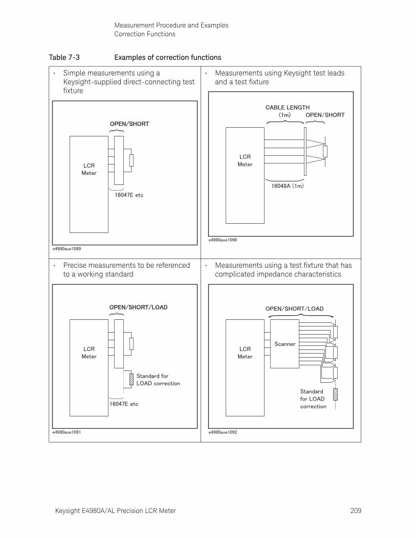
Keysight E4980A/AL Precision LCR Meter 209
Measurement Procedure and ExamplesCorrection Functions
Table 7-3 Examples of correction functions
• Simple measurements using a Keysight-supplied direct-connecting test fixture
• Measurements using Keysight test leads and a test fixture
• Precise measurements to be referenced to a working standard
• Measurements using a test fixture that has complicated impedance characteristics
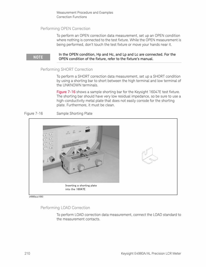
210 Keysight E4980A/AL Precision LCR Meter
Measurement Procedure and ExamplesCorrection Functions
7-
Performing OPEN Correction
To perform an OPEN correction data measurement, set up an OPEN condition where nothing is connected to the test fixture. While the OPEN measurement is being performed, don’t touch the test fixture or move your hands near it.
Performing SHORT Correction
To perform a SHORT correction data measurement, set up a SHORT condition by using a shorting bar to short between the high terminal and low terminal of the UNKNOWN terminals.
Figure 7-16 shows a sample shorting bar for the Keysight 16047E test fixture. The shorting bar should have very low residual impedance, so be sure to use a high-conductivity metal plate that does not easily corrode for the shorting plate. Furthermore, it must be clean.
Figure 7-16 Sample Shorting Plate
Performing LOAD Correction
To perform LOAD correction data measurement, connect the LOAD standard to the measurement contacts.
In the OPEN condition, Hp and Hc, and Lp and Lc are connected. For the OPEN condition of the fixture, refer to the fixture’s manual.
Keysight E4980A/AL Precision LCR Meter 211
Measurement Procedure and ExamplesCorrection Functions
Preparing the Standard
It is necessary to prepare a working standard, such as a standard resistor or standard capacitor. Try to select a standard whose impedance is as close as possible to the impedance of the DUT. Consider the following recommendations for selecting standards.
• For capacitance measurements:
A standard capacitor whose capacitance is nearly equal to the capacitance of the DUT is recommended.
• For resistance measurements:
A standard resistor whose resistance is nearly equal to the resistance of the DUT is recommended.
• For inductance measurements:
A standard inductor whose inductance is nearly equal to the inductance of the DUT is recommended.
Reference Values of the LOAD Standard
Enter specified reference values of the standard as the REF A and REF B values by using the appropriate function on the CORRECTION page. For example, when using a standard capacitor that has a specified parallel capacitance and D values, enter the specified parallel capacitance value as the REF A value and the specified D value as the REF B value with the Cp-D function.
Using the Pre-Measured Device for the LOAD
Even if you have no standard with the specified reference values, you can perform a LOAD correction using a device such as a general purpose capacitor or resistor. The pre-measured values of a device are used for the REF A and REF B values. Follow the procedure shown below to use a device for the LOAD standard.
Step 1. For the LOAD standard, prepare a device that has an impedance as close as possible to the impedance of the DUT.
Step 2. If the device has BNC connectors structured in the four-terminal pair configuration, measure the device directly by connecting it directly to the E4980A/AL: Do not use a test fixture. If the device does not have four-terminal pair measurement terminals, measure the device using a direct coupling test fixture (such as the Keysight 16047A/C/D/E).
Step 3. On the CORRECTION page, enter the measured values obtained in step 2 as the REF A and REF B values with the function used in step 2.
If the REF A and REF B values are entered with the Cp-D function, measurements with other functions (such as the |Z|- function) can also be performed.
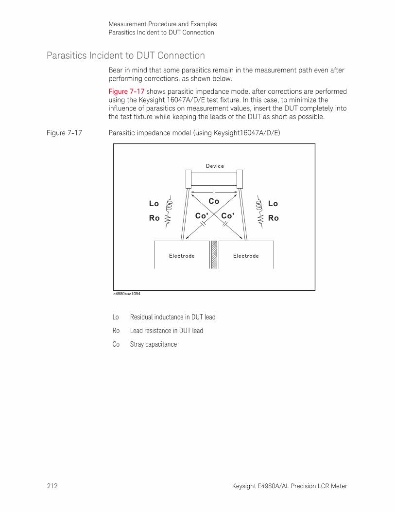
212 Keysight E4980A/AL Precision LCR Meter
Measurement Procedure and ExamplesParasitics Incident to DUT Connection
7-
Parasitics Incident to DUT ConnectionBear in mind that some parasitics remain in the measurement path even after performing corrections, as shown below.
Figure 7-17 shows parasitic impedance model after corrections are performed using the Keysight 16047A/D/E test fixture. In this case, to minimize the influence of parasitics on measurement values, insert the DUT completely into the test fixture while keeping the leads of the DUT as short as possible.
Figure 7-17 Parasitic impedance model (using Keysight16047A/D/E)
Lo Residual inductance in DUT lead
Ro Lead resistance in DUT lead
Co Stray capacitance
Lo Co
Co' Co'Ro
Lo
Ro

Keysight E4980A/AL Precision LCR Meter 213
Measurement Procedure and ExamplesCharacteristics Example
Characteristics ExampleTable 7-4 shows typical characteristics of various components. As can be seen in the figure, a component may have different effective parameter values depending on its operating conditions. The measured values most useful in actual applications are obtained from precise measurement under the actual operating conditions.
Table 7-4 Typical characteristics of components
DUT Characteristics Example Measurement Functions
Large C Cs-Rs, Cs-D,
Cs-Q,
R-X, |Z|-
Small C Cp-D, Cp-G,
G-B, |Y|-
Large L Lp-Rp, Lp-D
Lp-Q,
G-B, |Y|-
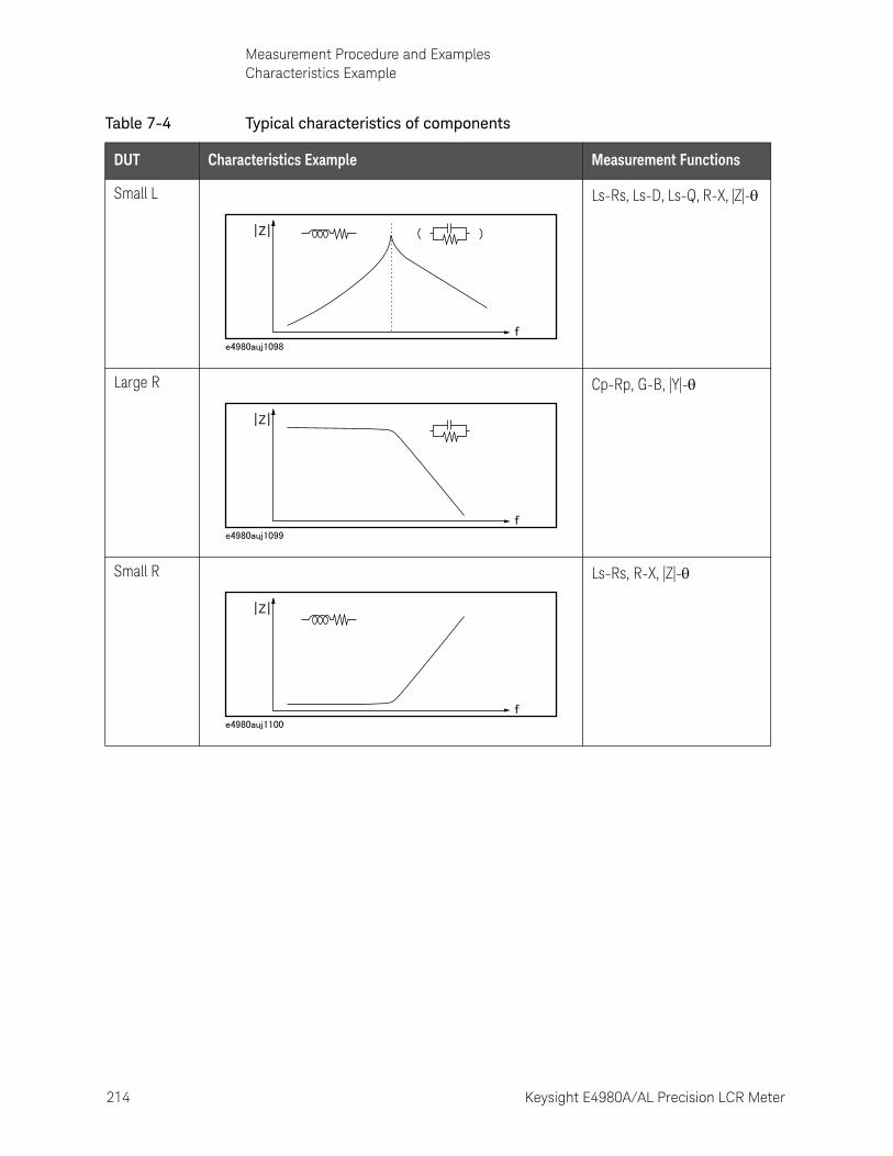
214 Keysight E4980A/AL Precision LCR Meter
Measurement Procedure and ExamplesCharacteristics Example
7-
Small L Ls-Rs, Ls-D, Ls-Q, R-X, |Z|-
Large R Cp-Rp, G-B, |Y|-
Small R Ls-Rs, R-X, |Z|-
Table 7-4 Typical characteristics of components
DUT Characteristics Example Measurement Functions
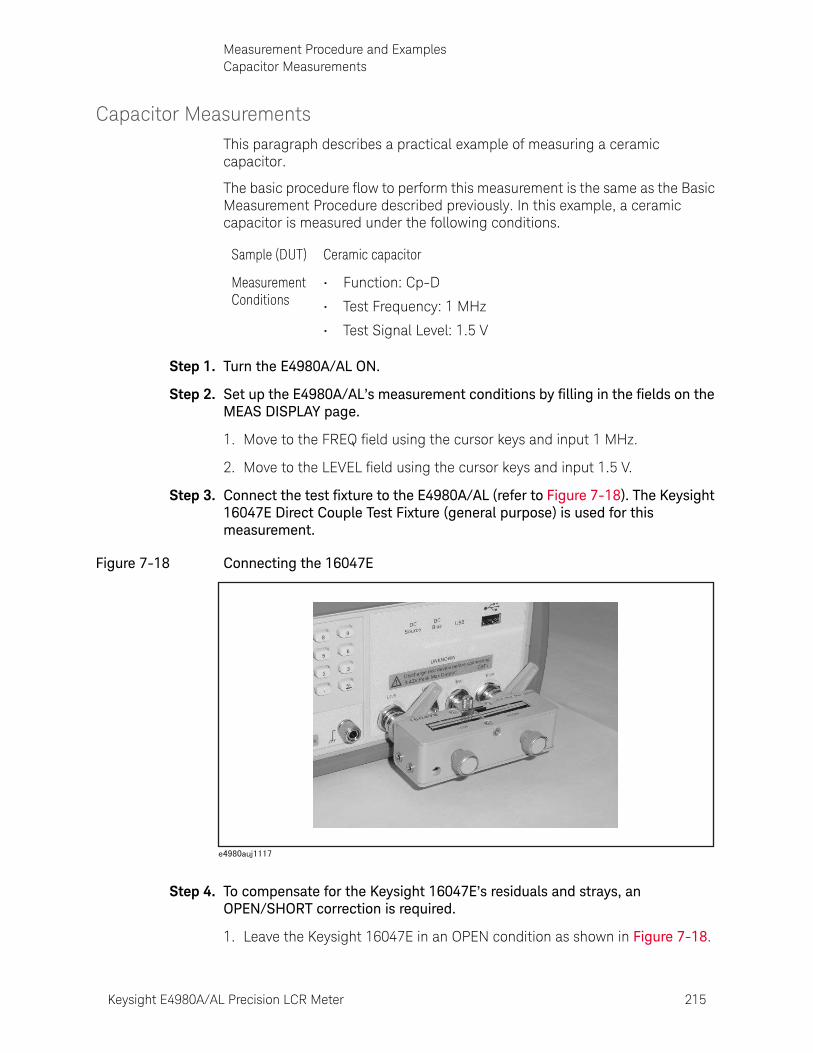
Keysight E4980A/AL Precision LCR Meter 215
Measurement Procedure and ExamplesCapacitor Measurements
Capacitor MeasurementsThis paragraph describes a practical example of measuring a ceramic capacitor.
The basic procedure flow to perform this measurement is the same as the Basic Measurement Procedure described previously. In this example, a ceramic capacitor is measured under the following conditions.
Step 1. Turn the E4980A/AL ON.
Step 2. Set up the E4980A/AL’s measurement conditions by filling in the fields on the MEAS DISPLAY page.
1. Move to the FREQ field using the cursor keys and input 1 MHz.
2. Move to the LEVEL field using the cursor keys and input 1.5 V.
Step 3. Connect the test fixture to the E4980A/AL (refer to Figure 7-18). The Keysight 16047E Direct Couple Test Fixture (general purpose) is used for this measurement.
Figure 7-18 Connecting the 16047E
Step 4. To compensate for the Keysight 16047E’s residuals and strays, an OPEN/SHORT correction is required.
1. Leave the Keysight 16047E in an OPEN condition as shown in Figure 7-18.
Sample (DUT) Ceramic capacitor
Measurement Conditions
• Function: Cp-D
• Test Frequency: 1 MHz
• Test Signal Level: 1.5 V
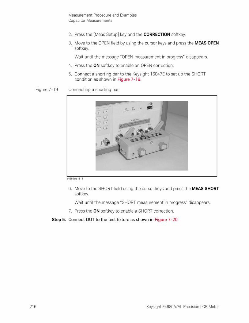
216 Keysight E4980A/AL Precision LCR Meter
Measurement Procedure and ExamplesCapacitor Measurements
7-
2. Press the [Meas Setup] key and the CORRECTION softkey.
3. Move to the OPEN field by using the cursor keys and press the MEAS OPEN softkey.
Wait until the message “OPEN measurement in progress” disappears.
4. Press the ON softkey to enable an OPEN correction.
5. Connect a shorting bar to the Keysight 16047E to set up the SHORT condition as shown in Figure 7-19.
Figure 7-19 Connecting a shorting bar
6. Move to the SHORT field using the cursor keys and press the MEAS SHORT softkey.
Wait until the message “SHORT measurement in progress” disappears.
7. Press the ON softkey to enable a SHORT correction.
Step 5. Connect DUT to the test fixture as shown in Figure 7-20
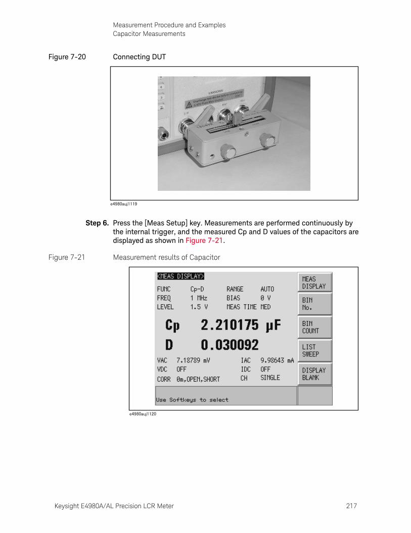
Keysight E4980A/AL Precision LCR Meter 217
Measurement Procedure and ExamplesCapacitor Measurements
Figure 7-20 Connecting DUT
Step 6. Press the [Meas Setup] key. Measurements are performed continuously by the internal trigger, and the measured Cp and D values of the capacitors are displayed as shown in Figure 7-21.
Figure 7-21 Measurement results of Capacitor
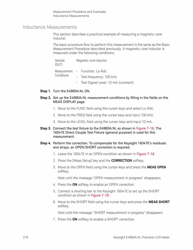
218 Keysight E4980A/AL Precision LCR Meter
Measurement Procedure and ExamplesInductance Measurements
7-
Inductance MeasurementsThis section describes a practical example of measuring a magnetic-core inductor.
The basic procedure flow to perform this measurement is the same as the Basic Measurement Procedure described previously. A magnetic-core inductor is measured under the following conditions.
Step 1. Turn the E4980A/AL ON.
Step 2. Set up the E4980A/AL measurement conditions by filling in the fields on the MEAS DISPLAY page.
1. Move to the FUNC field using the cursor keys and select Ls-Rdc.
2. Move to the FREQ field using the cursor keys and input 100 kHz.
3. Move to the LEVEL field using the cursor keys and input 10 mA.
Step 3. Connect the test fixture to the E4980A/AL as shown in Figure 7-18. The 16047E Direct Couple Test Fixture (general purpose) is used for this measurement.
Step 4. Perform the correction. To compensate for the Keysight 16047E’s residuals and strays, an OPEN/SHORT correction is required.
1. Leave the 16047E in an OPEN condition as shown in Figure 7-18.
2. Press the [Meas Setup] key and the CORRECTION softkey.
3. Move to the OPEN field using the cursor keys and press the MEAS OPEN softkey.
Wait until the message “OPEN measurement in progress” disappears.
4. Press the ON softkey to enable an OPEN correction.
5. Connect a shorting bar to the Keysight 16047E to set up the SHORT condition as shown in Figure 7-19.
6. Move to the SHORT field using the cursor keys and press the MEAS SHORT softkey.
Wait until the message “SHORT measurement in progress” disappears.
7. Press the ON softkey to enable a SHORT correction.
Sample (DUT)
Magnetic-core inductor
Measurement Conditions
• Function: Ls-Rdc
• Test frequency: 100 kHz
• Test Signal Level: 10 mA (constant)

Keysight E4980A/AL Precision LCR Meter 219
Measurement Procedure and ExamplesInductance Measurements
Step 5. Connect the DUT to the test fixture as shown in Figure 7-22.
Figure 7-22 Connecting DUT
Step 6. Press the [Meas Setup] key to display the MEAS DISPLAY page.
1. Move to the ALC field using the cursor keys to press the ON softkey.
When it is set to ON, the test signal current level through the DUT is set to a constant value (the value set in the LEVEL field).
Step 7. Press the [Meas Setup] key. Measurements are performed continuously by the internal trigger, and the measured Ls and Rdc values of the magnetic core inductor are displayed.
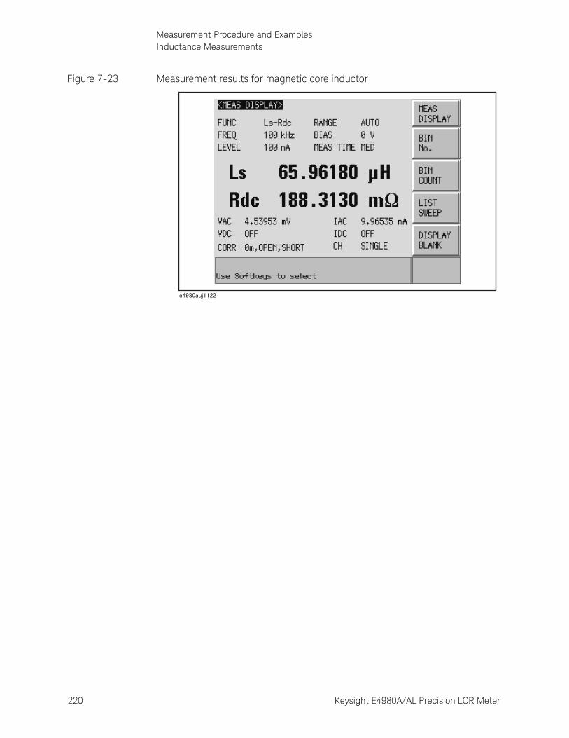
220 Keysight E4980A/AL Precision LCR Meter
Measurement Procedure and ExamplesInductance Measurements
7-
Figure 7-23 Measurement results for magnetic core inductor
Keysight E4980A/AL Precision LCR Meter 221
Measurement Procedure and ExamplesMeasurements Using DC source
Measurements Using DC sourceThis section describes a practical measurement example of the E4980A/AL using the DC source. The list sweep is used for this measurement. The basic procedure flow to perform this measurement is the same as the Basic Measurement Procedure described previously.
Step 1. Turn the E4980A/AL ON.
Step 2. Set up the E4980A/AL measurement conditions by filling in the fields on the MEAS DISPLAY page.
1. Move to the FUNC field using the cursor keys and select R-X.
Step 3. Press the [Meas Setup] key to set the following measurement conditions in each field of the LIST SWEEP SETUP page.
1. Set the list sweep parameter to DC SRC[V].
2. Enter the level of the sweep point.
Step 4. Connect the test fixture to the E4980A/AL as shown in Figure 7-18. The 16047E Direct Couple Test Fixture (general purpose) is used for this measurement.
Step 5. Perform the correction. To compensate the Keysight 16047E’s residuals and strays, an OPEN/SHORT correction is required.
1. Leave the 16047E in an OPEN condition as shown in Figure 7-18.
2. Press the [Meas Setup] key and the CORRECTION softkey.
3. Move to the OPEN field using the cursor keys and press the MEAS OPEN softkey.
Wait until the message “OPEN measurement in progress” disappears.
4. Press the ON softkey to enable an OPEN correction.
5. Connect a shorting bar to the Keysight 16047E to set up the SHORT condition as shown in Figure 7-19.
When option 001 is not installed, the DC source cannot be used.
The DC source has a 45mA current-supply capability. If you want to limit the base current of the transistor, insert a resistor between the DC source and the base.
Sample (DUT) Transistor
Measurement Conditions
• Function: R-X
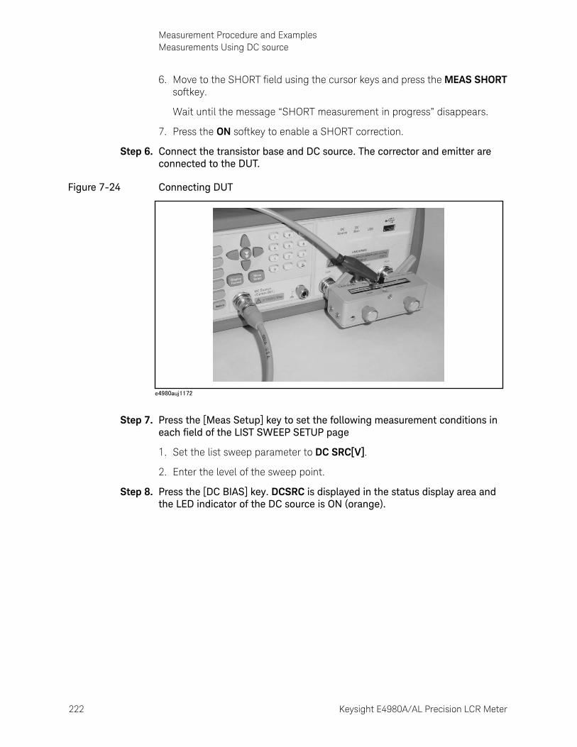
222 Keysight E4980A/AL Precision LCR Meter
Measurement Procedure and ExamplesMeasurements Using DC source
7-
6. Move to the SHORT field using the cursor keys and press the MEAS SHORT softkey.
Wait until the message “SHORT measurement in progress” disappears.
7. Press the ON softkey to enable a SHORT correction.
Step 6. Connect the transistor base and DC source. The corrector and emitter are connected to the DUT.
Figure 7-24 Connecting DUT
Step 7. Press the [Meas Setup] key to set the following measurement conditions in each field of the LIST SWEEP SETUP page
1. Set the list sweep parameter to DC SRC[V].
2. Enter the level of the sweep point.
Step 8. Press the [DC BIAS] key. DCSRC is displayed in the status display area and the LED indicator of the DC source is ON (orange).
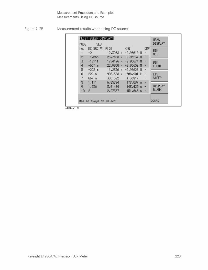
Keysight E4980A/AL Precision LCR Meter 223
Measurement Procedure and ExamplesMeasurements Using DC source
Figure 7-25 Measurement results when using DC source

224 Keysight E4980A/AL Precision LCR Meter
Measurement Procedure and ExamplesMeasurements Using DC source
7-
225
Keysight E4980A/AL Precision LCR Meter
User’s Guide
8 Overview of Remote Control
This chapter provides an overview of the remote control system and the SCPI commands.
Types of remote control systemDepending on the system controller and the interface, you can configure three types of remote control system as shown in the table below.
System controller Interface Overview
External Controller (external computer such as PC)
GPIB System to control the E4980A/AL and other devices connected via GPIB from the external controller. For more information, refer to “GPIB remote control system” on page 226.
LAN System to control the E4980A/AL and other devices connected via LAN from the external controller. For more information, refer to “LAN remote control system” on page 228.
USB System to control the E4980A/AL and other devices connected via USB from the external controller. For more information, refer to “USB Remote Control System” on page 240.
You must install Keysight I/O Libraries Suite in the external controller in advance.
Use Keysight I/O Libraries Suite 14 or higher.
For further information on I/O Libraries Suite, see the Keysight I/O Libraries Suite manual.
Keysight I/O Libraries Suite may not be available for certain external controllers or OS versions. For further details, refer to the Help guidance for Keysight I/O Libraries Suite.
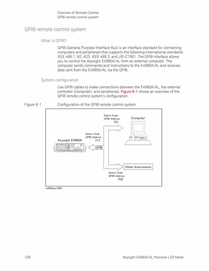
226 Keysight E4980A/AL Precision LCR Meter
Overview of Remote ControlGPIB remote control system
8-
GPIB remote control system
What is GPIB?
GPIB (General Purpose Interface Bus) is an interface standard for connecting computers and peripherals that supports the following international standards: IEEE 488.1, IEC-625, IEEE 488.2, and JIS-C1901. The GPIB interface allows you to control the Keysight E4980A/AL from an external computer. The computer sends commands and instructions to the E4980A/AL and receives data sent from the E4980A/AL via the GPIB.
System configuration
Use GPIB cables to make connections between the E4980A/AL, the external controller (computer), and peripherals. Figure 8-1 shows an overview of the GPIB remote control system’s configuration.
Figure 8-1 Configuration of the GPIB remote control system
E4980APrecision LCR Meter
20 Hz - 2 MHz
LCUR LPOT HPOT HCUR
DCBias USB
DCSource
UNKNOWN
Discharge test device before connecting42V Peak Max Output CAT I
10VDC Max
DC Source(Option 001)
Trigger
DC Bias
DCSource
Return
7 8 9
4 5 6
1 2 3
0 .
Preset
DisplayFormat
MeasSetup
Recall A Recall B Save/Recall System Local/
Lock
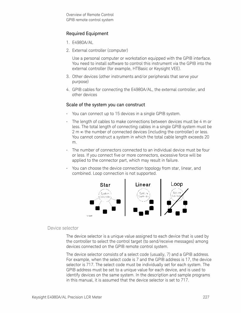
Keysight E4980A/AL Precision LCR Meter 227
Overview of Remote ControlGPIB remote control system
Required Equipment
1. E4980A/AL
2. External controller (computer)
Use a personal computer or workstation equipped with the GPIB interface. You need to install software to control this instrument via the GPIB into the external controller (for example, HTBasic or Keysight VEE).
3. Other devices (other instruments and/or peripherals that serve your purpose)
4. GPIB cables for connecting the E4980A/AL, the external controller, and other devices
Scale of the system you can construct
• You can connect up to 15 devices in a single GPIB system.
• The length of cables to make connections between devices must be 4 m or less. The total length of connecting cables in a single GPIB system must be 2 m the number of connected devices (including the controller) or less. You cannot construct a system in which the total cable length exceeds 20 m.
• The number of connectors connected to an individual device must be four or less. If you connect five or more connectors, excessive force will be applied to the connector part, which may result in failure.
• You can choose the device connection topology from star, linear, and combined. Loop connection is not supported.
Device selector
The device selector is a unique value assigned to each device that is used by the controller to select the control target (to send/receive messages) among devices connected on the GPIB remote control system.
The device selector consists of a select code (usually, 7) and a GPIB address. For example, when the select code is 7 and the GPIB address is 17, the device selector is 717. The select code must be individually set for each system. The GPIB address must be set to a unique value for each device, and is used to identify devices on the same system. In the description and sample programs in this manual, it is assumed that the device selector is set to 717.
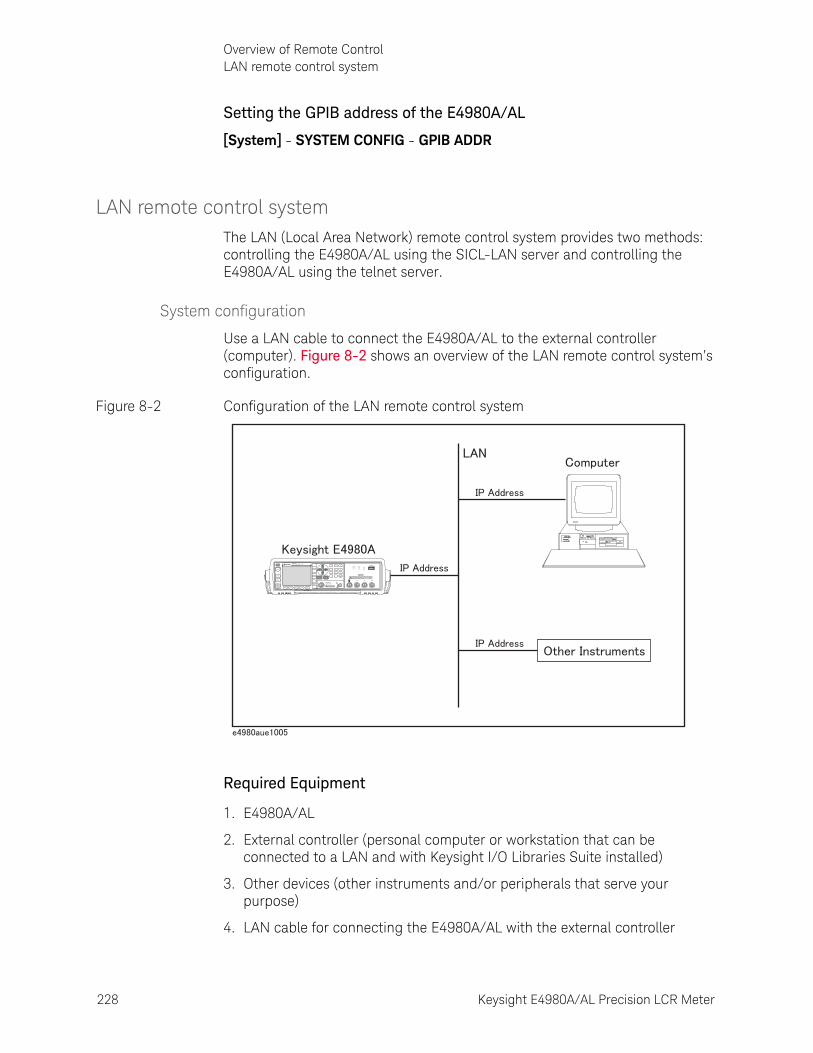
228 Keysight E4980A/AL Precision LCR Meter
Overview of Remote ControlLAN remote control system
8-
Setting the GPIB address of the E4980A/AL
[System] - SYSTEM CONFIG - GPIB ADDR
LAN remote control systemThe LAN (Local Area Network) remote control system provides two methods: controlling the E4980A/AL using the SICL-LAN server and controlling the E4980A/AL using the telnet server.
System configuration
Use a LAN cable to connect the E4980A/AL to the external controller (computer). Figure 8-2 shows an overview of the LAN remote control system’s configuration.
Figure 8-2 Configuration of the LAN remote control system
Required Equipment
1. E4980A/AL
2. External controller (personal computer or workstation that can be connected to a LAN and with Keysight I/O Libraries Suite installed)
3. Other devices (other instruments and/or peripherals that serve your purpose)
4. LAN cable for connecting the E4980A/AL with the external controller
E4980APrecision LCR Meter
20 Hz - 2 MHz
LCUR LPOT HPOT HCUR
DCBias USB
DCSource
UNKNOWN
Discharge test device before connecting42V Peak Max Output CAT I
10VDC Max
DC Source(Option 001)
Trigger
DC Bias
DCSource
Return
7 8 9
4 5 6
1 2 3
0 .
Preset
DisplayFormat
MeasSetup
Recall A Recall B Save/Recall System Local/
Lock

Keysight E4980A/AL Precision LCR Meter 229
Overview of Remote ControlLAN remote control system
Preparing the E4980A/AL
Before controlling the E4980A/AL via a LAN, you need to configure the network function. For detailed information on the procedure, refer to Chapter 5, “System Configurations.”.
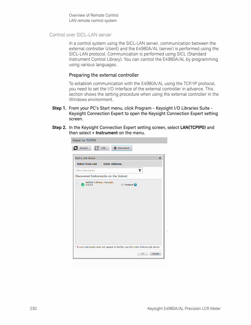
230 Keysight E4980A/AL Precision LCR Meter
Overview of Remote ControlLAN remote control system
8-
Control over SICL-LAN server
In a control system using the SICL-LAN server, communication between the external controller (client) and the E4980A/AL (server) is performed using the SICL-LAN protocol. Communication is performed using SICL (Standard Instrument Control Library). You can control the E4980A/AL by programming using various languages.
Preparing the external controller
To establish communication with the E4980A/AL using the TCP/IP protocol, you need to set the I/O interface of the external controller in advance. This section shows the setting procedure when using the external controller in the Windows environment.
Step 1. From your PC’s Start menu, click Program - Keysight I/O Libraries Suite - Keysight Connection Expert to open the Keysight Connection Expert setting screen.
Step 2. In the Keysight Connection Expert setting screen, select LAN(TCPIP0) and then select + Instrument on the menu.
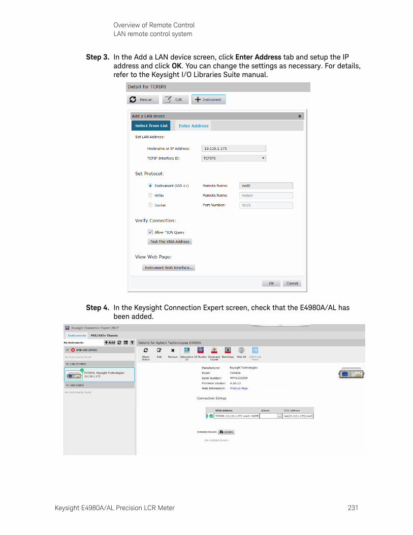
Keysight E4980A/AL Precision LCR Meter 231
Overview of Remote ControlLAN remote control system
Step 3. In the Add a LAN device screen, click Enter Address tab and setup the IP address and click OK. You can change the settings as necessary. For details, refer to the Keysight I/O Libraries Suite manual.
Step 4. In the Keysight Connection Expert screen, check that the E4980A/AL has been added.
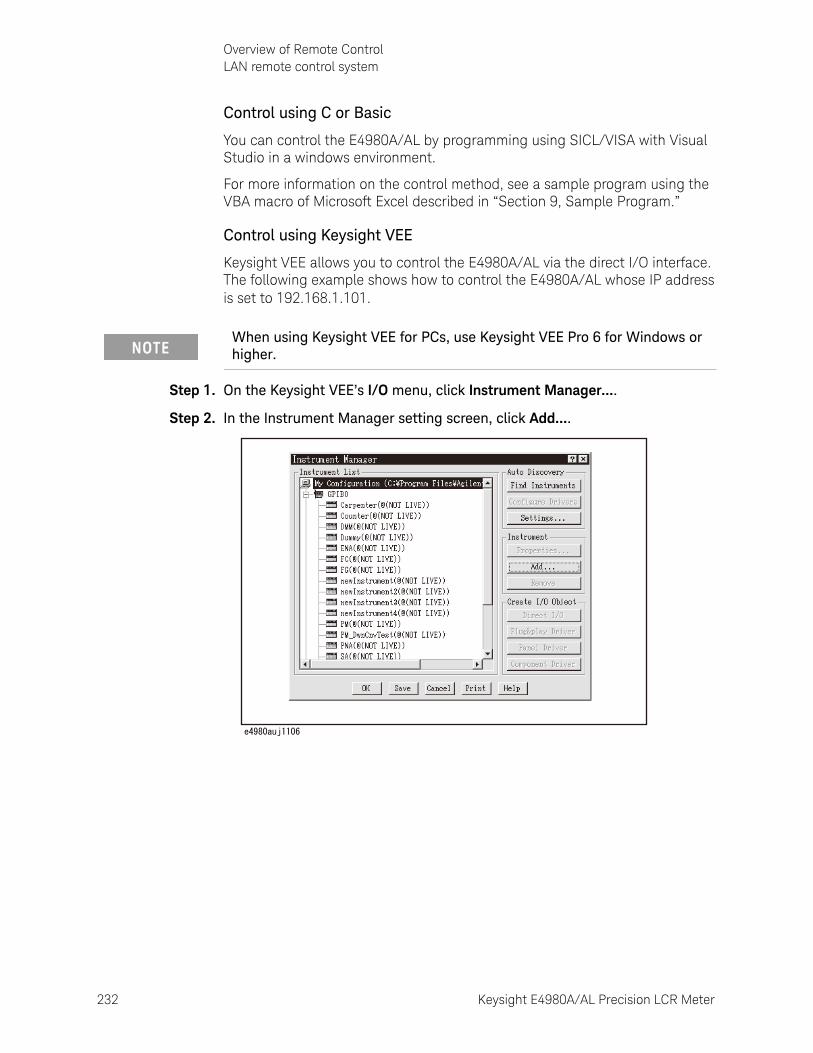
232 Keysight E4980A/AL Precision LCR Meter
Overview of Remote ControlLAN remote control system
8-
Control using C or Basic
You can control the E4980A/AL by programming using SICL/VISA with Visual Studio in a windows environment.
For more information on the control method, see a sample program using the VBA macro of Microsoft Excel described in “Section 9, Sample Program.”
Control using Keysight VEE
Keysight VEE allows you to control the E4980A/AL via the direct I/O interface. The following example shows how to control the E4980A/AL whose IP address is set to 192.168.1.101.
Step 1. On the Keysight VEE’s I/O menu, click Instrument Manager....
Step 2. In the Instrument Manager setting screen, click Add....
When using Keysight VEE for PCs, use Keysight VEE Pro 6 for Windows or higher.
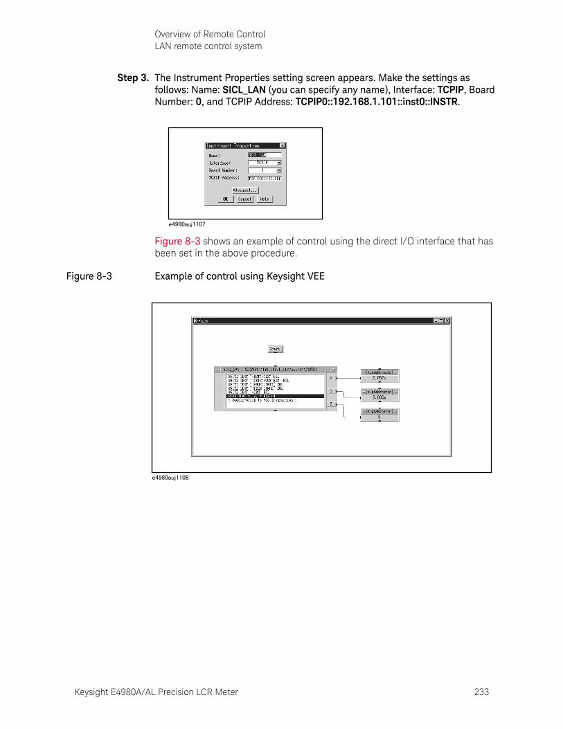
Keysight E4980A/AL Precision LCR Meter 233
Overview of Remote ControlLAN remote control system
Step 3. The Instrument Properties setting screen appears. Make the settings as follows: Name: SICL_LAN (you can specify any name), Interface: TCPIP, Board Number: 0, and TCPIP Address: TCPIP0::192.168.1.101::inst0::INSTR.
Figure 8-3 shows an example of control using the direct I/O interface that has been set in the above procedure.
Figure 8-3 Example of control using Keysight VEE
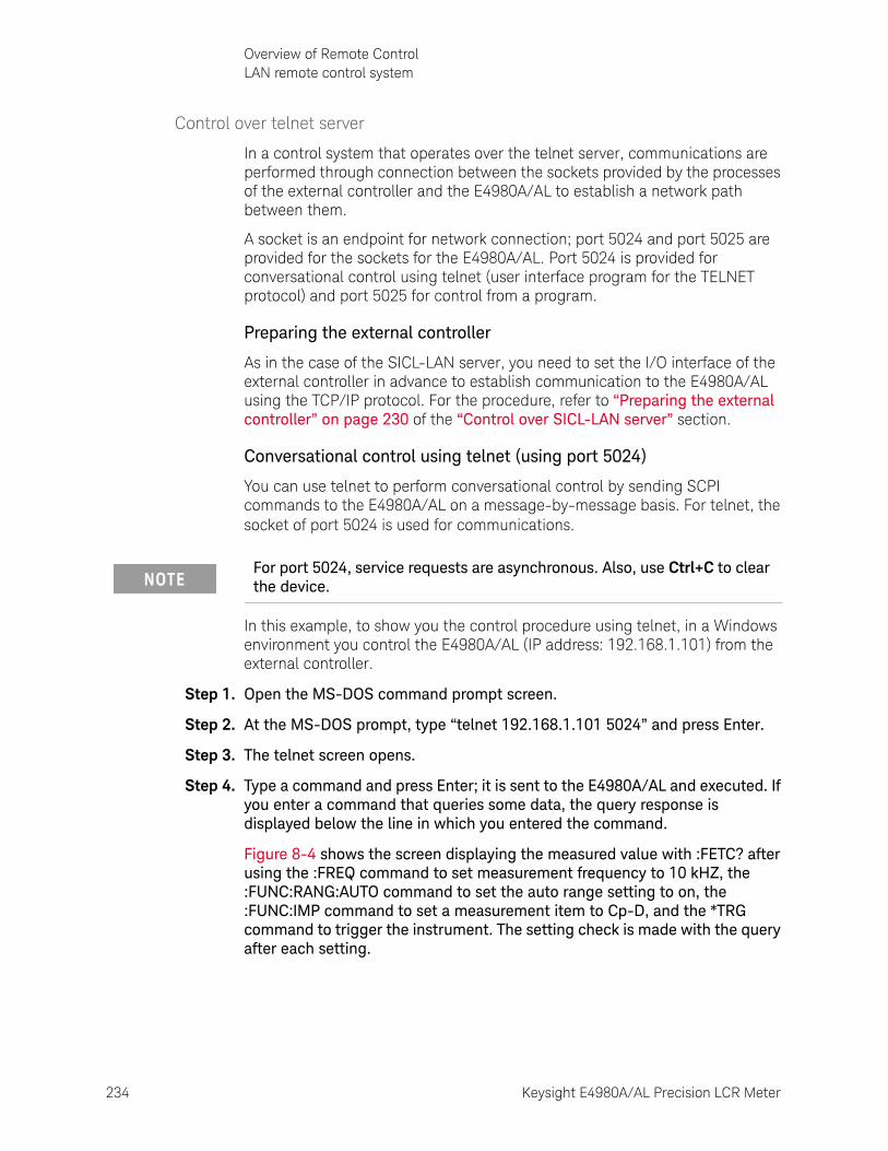
234 Keysight E4980A/AL Precision LCR Meter
Overview of Remote ControlLAN remote control system
8-
Control over telnet server
In a control system that operates over the telnet server, communications are performed through connection between the sockets provided by the processes of the external controller and the E4980A/AL to establish a network path between them.
A socket is an endpoint for network connection; port 5024 and port 5025 are provided for the sockets for the E4980A/AL. Port 5024 is provided for conversational control using telnet (user interface program for the TELNET protocol) and port 5025 for control from a program.
Preparing the external controller
As in the case of the SICL-LAN server, you need to set the I/O interface of the external controller in advance to establish communication to the E4980A/AL using the TCP/IP protocol. For the procedure, refer to “Preparing the external controller” on page 230 of the “Control over SICL-LAN server” section.
Conversational control using telnet (using port 5024)
You can use telnet to perform conversational control by sending SCPI commands to the E4980A/AL on a message-by-message basis. For telnet, the socket of port 5024 is used for communications.
In this example, to show you the control procedure using telnet, in a Windows environment you control the E4980A/AL (IP address: 192.168.1.101) from the external controller.
Step 1. Open the MS-DOS command prompt screen.
Step 2. At the MS-DOS prompt, type “telnet 192.168.1.101 5024” and press Enter.
Step 3. The telnet screen opens.
Step 4. Type a command and press Enter; it is sent to the E4980A/AL and executed. If you enter a command that queries some data, the query response is displayed below the line in which you entered the command.
Figure 8-4 shows the screen displaying the measured value with :FETC? after using the :FREQ command to set measurement frequency to 10 kHZ, the :FUNC:RANG:AUTO command to set the auto range setting to on, the :FUNC:IMP command to set a measurement item to Cp-D, and the *TRG command to trigger the instrument. The setting check is made with the query after each setting.
For port 5024, service requests are asynchronous. Also, use Ctrl+C to clear the device.
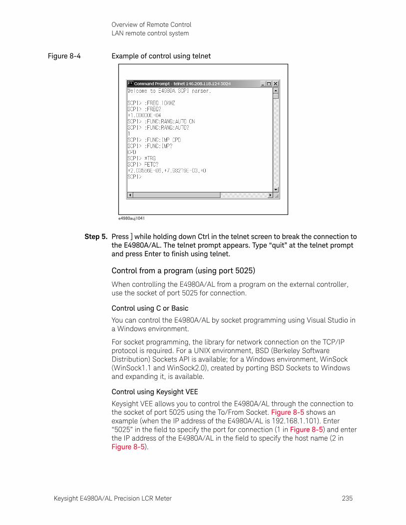
Keysight E4980A/AL Precision LCR Meter 235
Overview of Remote ControlLAN remote control system
Figure 8-4 Example of control using telnet
Step 5. Press ] while holding down Ctrl in the telnet screen to break the connection to the E4980A/AL. The telnet prompt appears. Type “quit” at the telnet prompt and press Enter to finish using telnet.
Control from a program (using port 5025)
When controlling the E4980A/AL from a program on the external controller, use the socket of port 5025 for connection.
Control using C or Basic
You can control the E4980A/AL by socket programming using Visual Studio in a Windows environment.
For socket programming, the library for network connection on the TCP/IP protocol is required. For a UNIX environment, BSD (Berkeley Software Distribution) Sockets API is available; for a Windows environment, WinSock (WinSock1.1 and WinSock2.0), created by porting BSD Sockets to Windows and expanding it, is available.
Control using Keysight VEE
Keysight VEE allows you to control the E4980A/AL through the connection to the socket of port 5025 using the To/From Socket. Figure 8-5 shows an example (when the IP address of the E4980A/AL is 192.168.1.101). Enter “5025” in the field to specify the port for connection (1 in Figure 8-5) and enter the IP address of the E4980A/AL in the field to specify the host name (2 in Figure 8-5).
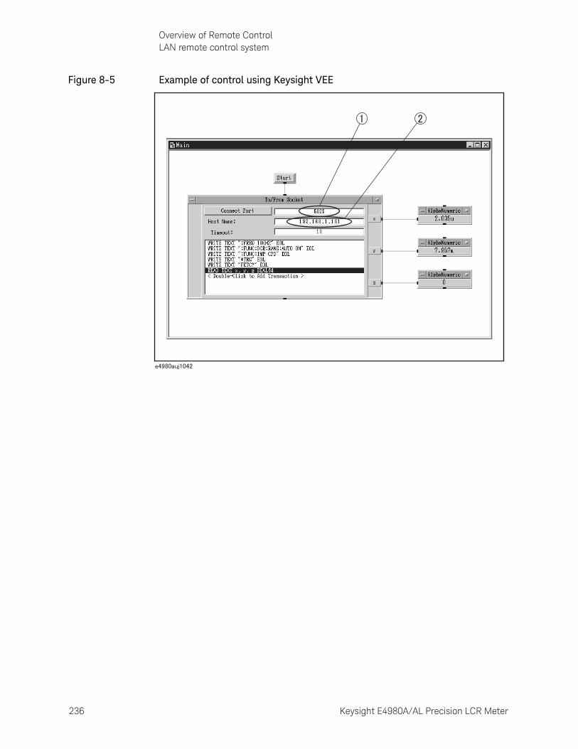
236 Keysight E4980A/AL Precision LCR Meter
Overview of Remote ControlLAN remote control system
8-
Figure 8-5 Example of control using Keysight VEE
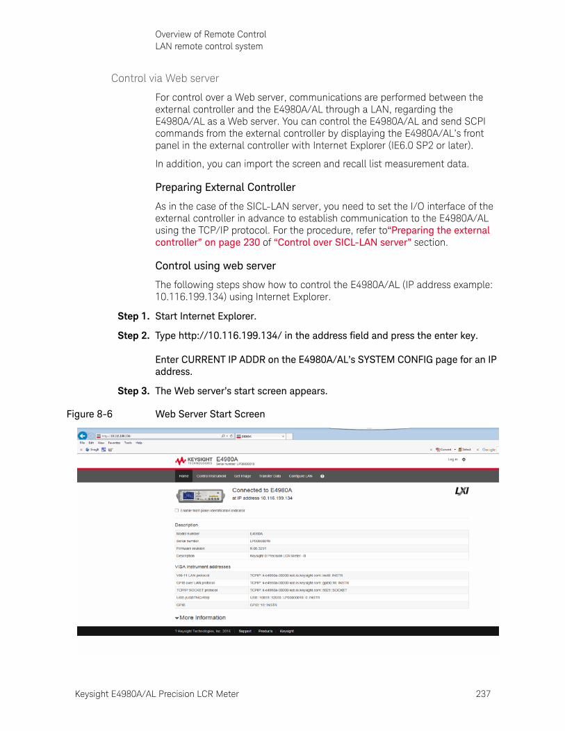
Keysight E4980A/AL Precision LCR Meter 237
Overview of Remote ControlLAN remote control system
Control via Web server
For control over a Web server, communications are performed between the external controller and the E4980A/AL through a LAN, regarding the E4980A/AL as a Web server. You can control the E4980A/AL and send SCPI commands from the external controller by displaying the E4980A/AL’s front panel in the external controller with Internet Explorer (IE6.0 SP2 or later).
In addition, you can import the screen and recall list measurement data.
Preparing External Controller
As in the case of the SICL-LAN server, you need to set the I/O interface of the external controller in advance to establish communication to the E4980A/AL using the TCP/IP protocol. For the procedure, refer to“Preparing the external controller” on page 230 of “Control over SICL-LAN server” section.
Control using web server
The following steps show how to control the E4980A/AL (IP address example: 10.116.199.134) using Internet Explorer.
Step 1. Start Internet Explorer.
Step 2. Type http://10.116.199.134/ in the address field and press the enter key.Enter CURRENT IP ADDR on the E4980A/AL’s SYSTEM CONFIG page for an IP address.
Step 3. The Web server’s start screen appears.
Figure 8-6 Web Server Start Screen
238 Keysight E4980A/AL Precision LCR Meter
Overview of Remote ControlLAN remote control system
8-
Web Server Function
The Web Server function consists of the following pages.
Page Description
Welcome Page Displays various setting information
Control Instrument Virtual front panel and sending/reading SCPI commands
Get Image Receives images
Transfer Data Receives test results
Configure LAN Displays and edit the LAN configuration
Displays the Help page?

Keysight E4980A/AL Precision LCR Meter 239
Overview of Remote ControlLAN remote control system
Password of Configure LAN
For the Web Server function, a password must be entered.
The default password is “Keysight”.
Changing the Password of the Configure LAN
You can change the password from the Gear icon on the right upper corner.
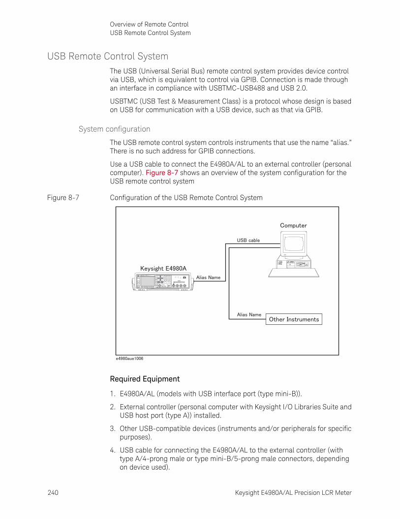
240 Keysight E4980A/AL Precision LCR Meter
Overview of Remote ControlUSB Remote Control System
8-
USB Remote Control SystemThe USB (Universal Serial Bus) remote control system provides device control via USB, which is equivalent to control via GPIB. Connection is made through an interface in compliance with USBTMC-USB488 and USB 2.0.
USBTMC (USB Test & Measurement Class) is a protocol whose design is based on USB for communication with a USB device, such as that via GPIB.
System configuration
The USB remote control system controls instruments that use the name “alias.” There is no such address for GPIB connections.
Use a USB cable to connect the E4980A/AL to an external controller (personal computer). Figure 8-7 shows an overview of the system configuration for the USB remote control system
Figure 8-7 Configuration of the USB Remote Control System
Required Equipment
1. E4980A/AL (models with USB interface port (type mini-B)).
2. External controller (personal computer with Keysight I/O Libraries Suite and USB host port (type A)) installed.
3. Other USB-compatible devices (instruments and/or peripherals for specific purposes).
4. USB cable for connecting the E4980A/AL to the external controller (with type A/4-prong male or type mini-B/5-prong male connectors, depending on device used).
E4980APrecision LCR Meter
20 Hz - 2 MHz
LCUR LPOT HPOT HCUR
DCBias USB
DCSource
UNKNOWN
Discharge test device before connecting42V Peak Max Output CAT I
10VDC Max
DC Source(Option 001)
Trigger
DC Bias
DCSource
Return
7 8 9
4 5 6
1 2 3
0 .
Preset
DisplayFormat
MeasSetup
Recall A Recall B Save/Recall System Local/
Lock
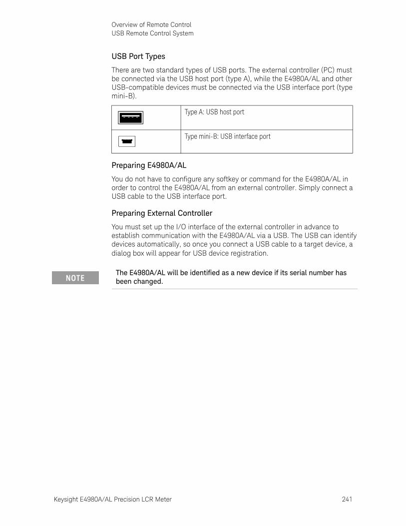
Keysight E4980A/AL Precision LCR Meter 241
Overview of Remote ControlUSB Remote Control System
USB Port Types
There are two standard types of USB ports. The external controller (PC) must be connected via the USB host port (type A), while the E4980A/AL and other USB-compatible devices must be connected via the USB interface port (type mini-B).
Preparing E4980A/AL
You do not have to configure any softkey or command for the E4980A/AL in order to control the E4980A/AL from an external controller. Simply connect a USB cable to the USB interface port.
Preparing External Controller
You must set up the I/O interface of the external controller in advance to establish communication with the E4980A/AL via a USB. The USB can identify devices automatically, so once you connect a USB cable to a target device, a dialog box will appear for USB device registration.
Type A: USB host port
Type mini-B: USB interface port
The E4980A/AL will be identified as a new device if its serial number has been changed.
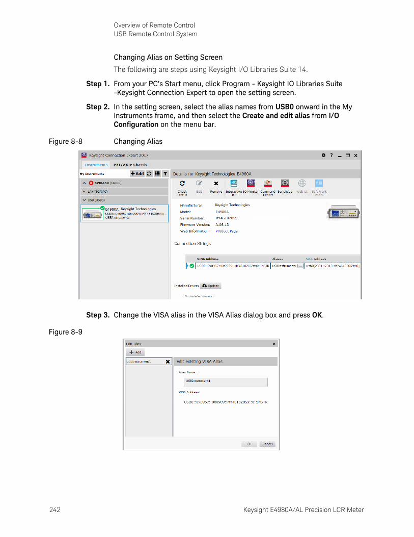
242 Keysight E4980A/AL Precision LCR Meter
Overview of Remote ControlUSB Remote Control System
8-
Changing Alias on Setting Screen
The following are steps using Keysight I/O Libraries Suite 14.
Step 1. From your PC’s Start menu, click Program - Keysight IO Libraries Suite -Keysight Connection Expert to open the setting screen.
Step 2. In the setting screen, select the alias names from USB0 onward in the My Instruments frame, and then select the Create and edit alias from I/O Configuration on the menu bar.
Figure 8-8 Changing Alias
Step 3. Change the VISA alias in the VISA Alias dialog box and press OK.
Figure 8-9
Keysight E4980A/AL Precision LCR Meter 243
Overview of Remote ControlUSB Remote Control System
Control using C or Basic
You can control the E4980A/AL by programming using SICL/VISA with Visual Studio in a Windows environment. For further information on controlling the E4980A/AL, see the manual for SICL or VISA. For Keysight I/O Libraries Suite, use Keysight I/O Libraries Suite 14.
You may employ aliases in programming using SICL/VISA.
The following example shows an OPEN command to control the E4980A/AL, for which the alias is E4980_USBIF.
SICL id = iopen ("E4980_USBIF")
VISA viOpen (...,"E4980_USBIF",...)
For further details on the programming using SICL/VISA, see the SICL Users Guide or the VISA Users Guide.

244 Keysight E4980A/AL Precision LCR Meter
Overview of Remote ControlUSB Remote Control System
8-
Control using Keysight VEE
Keysight VEE allows you to control the E4980A/AL via the direct I/O interface. The following example shows how to control the E4980A/AL, for which alias is given as E4980_USBIF.
Step 1. On the Keysight VEE's I/O menu, click Instrument Manager...
Step 2. In the Instrument Manager setting screen, click Add... and in the Add Interface/Device screen select USB.
Step 3. The Instrument Properties dialog box appears. Specify Name: E4980_USBIF(any other name acceptable), Interface: USB, Board Number: 0 (USB port number), and Alias: E4980_USBIF (which is registered in the IO Config setting screen), then click OK.
Figure 8-10 shows an example of control using the direct I/O interface that was set in the above procedures.
When using Keysight VEE for PCs, use Keysight VEE Pro 7 for Windows or a later version.
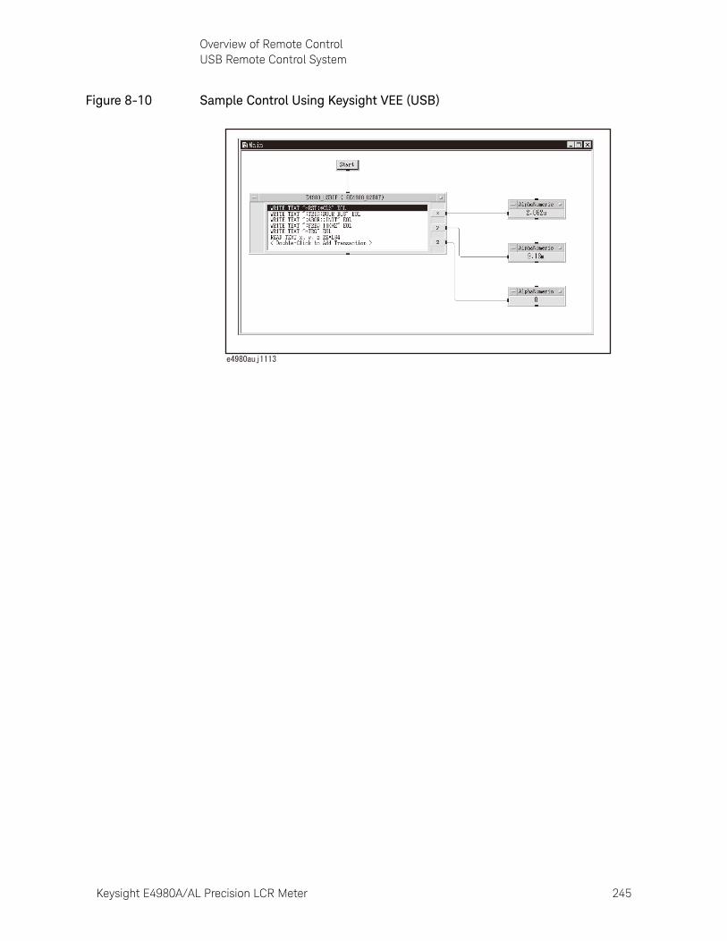
Keysight E4980A/AL Precision LCR Meter 245
Overview of Remote ControlUSB Remote Control System
Figure 8-10 Sample Control Using Keysight VEE (USB)
246 Keysight E4980A/AL Precision LCR Meter
Overview of Remote ControlSending SCPI command messages
8-
Sending SCPI command messages
Types and structure of commands
The SCPI commands available for the E4980A/AL are classified into two groups as follows.
E4980A/AL commands
Commands specific to the E4980A/AL. They cover all measurement functions that the E4980A/AL has and some general-purpose functions. The commands in this group are arranged in a hierarchical structure called the command tree (see “Command Tree” on page 388). Each command consists of character strings (mnemonics) indicating each hierarchical level and colon (:) separators between hierarchical levels.
IEEE common commands
Commands to cover general-purpose functions defined in IEEE488.2 that are commonly available to instruments that support this standard. The commands in this group have an asterisk (*) at the beginning. There is no hierarchical structure for the commands in this group.
Concepts of the command tree
The commands at the top of the command tree are called “root commands” or simply “roots.” To access lower-level commands in the tree, you need to specify a specific path like a directory path in the DOS file system. After turning the power on or resetting your PC, the current path is set to the root. Special characters in messages change the path setting as described below.
Message terminator A message terminator such as the <new line> character sets the current path to the root.
Colon (:) A colon between two command mnemonics lowers the level of the current path in the command tree. A colon used as the first character of a command specifies the command mnemonic that follows as the root-level command.
Semicolon (;) A semicolon does not change the current path but separates two commands in the same message.
Figure 8-11 shows an example of how to use colons and semicolons to efficiently access commands in the command tree.
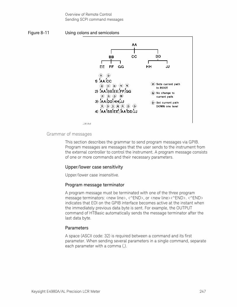
Keysight E4980A/AL Precision LCR Meter 247
Overview of Remote ControlSending SCPI command messages
Figure 8-11 Using colons and semicolons
Grammar of messages
This section describes the grammar to send program messages via GPIB. Program messages are messages that the user sends to the instrument from the external controller to control the instrument. A program message consists of one or more commands and their necessary parameters.
Upper/lower case sensitivity
Upper/lower case insensitive.
Program message terminator
A program message must be terminated with one of the three program message terminators: <new line>, <^END>, or <new line><^END>. <^END> indicates that EOI on the GPIB interface becomes active at the instant when the immediately previous data byte is sent. For example, the OUTPUT command of HTBasic automatically sends the message terminator after the last data byte.
Parameters
A space (ASCII code: 32) is required between a command and its first parameter. When sending several parameters in a single command, separate each parameter with a comma (,).
248 Keysight E4980A/AL Precision LCR Meter
Overview of Remote ControlSending SCPI command messages
8-
Message including several commands
When sending two or more commands in a single message, separate each command with a semicolon (;). The following example shows how to send the *CLS command and the :STAT:PRES command in a single message using HTBasic.
OUTPUT 717;"*CLS;:STAT:PRES"
Remote mode
The E4980A/AL enters remote mode when controlled with commands from the controller and RMT is displayed in the status display area in the lower right of the screen.
Press [Local/Lock] to cancel the remote mode.
When the E4980A/AL enters a local lockout state by sending the LOCAL LOCK BUS command from the controller, you cannot unlock the remote mode even if you press [Local/Lock]. (Only RMT is displayed in the status display area, so you cannot distinguish the local lockout state from a normal remote mode.)
Send the LOCAL BUS command from the controller to cancel this state, which enables control of the E4980A/AL on the front panel.
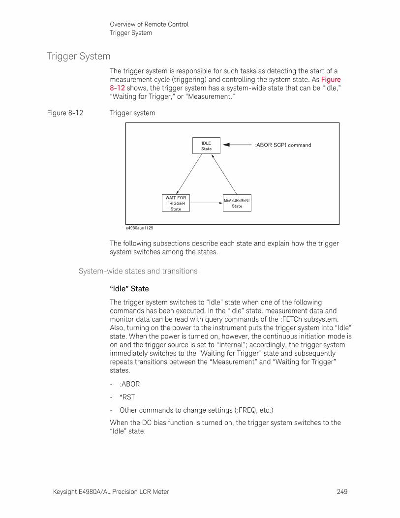
Keysight E4980A/AL Precision LCR Meter 249
Overview of Remote ControlTrigger System
Trigger SystemThe trigger system is responsible for such tasks as detecting the start of a measurement cycle (triggering) and controlling the system state. As Figure 8-12 shows, the trigger system has a system-wide state that can be “Idle,” “Waiting for Trigger,” or “Measurement.”
Figure 8-12 Trigger system
The following subsections describe each state and explain how the trigger system switches among the states.
System-wide states and transitions
“Idle” State
The trigger system switches to “Idle” state when one of the following commands has been executed. In the “Idle” state. measurement data and monitor data can be read with query commands of the :FETCh subsystem. Also, turning on the power to the instrument puts the trigger system into “Idle” state. When the power is turned on, however, the continuous initiation mode is on and the trigger source is set to “Internal”; accordingly, the trigger system immediately switches to the “Waiting for Trigger” state and subsequently repeats transitions between the “Measurement” and “Waiting for Trigger” states.
• :ABOR
• *RST
• Other commands to change settings (:FREQ, etc.)
When the DC bias function is turned on, the trigger system switches to the “Idle” state.
250 Keysight E4980A/AL Precision LCR Meter
Overview of Remote ControlTrigger System
8-
When starting the trigger system with one of the following commands, the system switches from “Idle” to the “Waiting for Trigger” state. The conditions of transition differ depending on which trigger source is specified (Refer to Figure 8-14 on page 253 and Figure 8-15 on page 254).
• :INIT[:IMM]
• :INIT:CONT
When the trigger source is set to the external trigger (EXT), the conditions for switching from “Idle” to “Waiting for Trigger” differ between the remote mode and local mode.
Remote mode When the :INIT:CONT is ON, the trigger system automatically switches to “Waiting for Trigger.”
When the :INIT:CONT is OFF, the trigger system switches to the “Waiting for Trigger” state by sending the :INIT:IMM command.
Local mode The trigger system automatically switches from “Idle” to “Waiting for Trigger.”
When the trigger source is set to the internal trigger (INT) or manual trigger (MAN), the trigger system automatically switches from the “Idle” state to the “Waiting for Trigger” state.
“Waiting for Trigger” State
When the trigger system is in the “Waiting for Trigger” state and either the instrument is triggered (i.e., a trigger is detected) or one of the following commands is executed, the trigger system switches to the “Measurement” state.
• :TRIG
As shown in the table below, the instrument is triggered differently depending on which trigger source is specified. To specify the trigger source, use the :TRIG:SOUR command.
The E4980A/AL in the “Idle” state switches to the “Measurement” state by using the :TRIG command.
When the :ABOR command is executed, the trigger system switches to the “Idle” state regardless of which state the E4980A/AL is currently in. An error occurs when query commands of the :FETCh subsystem are executed because no measurement data exist.
Trigger Source How instrument is triggered
Internal trigger(Internal)
The instrument is automatically triggered within itself.
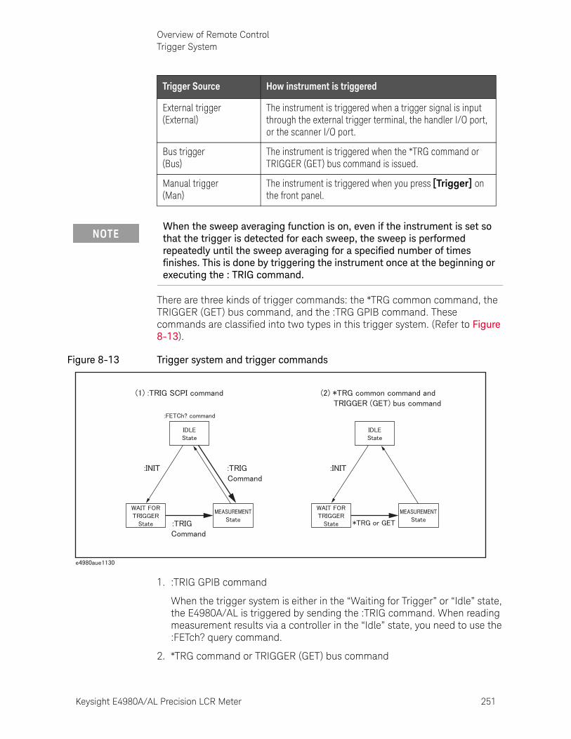
Keysight E4980A/AL Precision LCR Meter 251
Overview of Remote ControlTrigger System
There are three kinds of trigger commands: the *TRG common command, the TRIGGER (GET) bus command, and the :TRG GPIB command. These commands are classified into two types in this trigger system. (Refer to Figure 8-13).
Figure 8-13 Trigger system and trigger commands
1. :TRIG GPIB command
When the trigger system is either in the “Waiting for Trigger” or “Idle” state, the E4980A/AL is triggered by sending the :TRIG command. When reading measurement results via a controller in the “Idle” state, you need to use the :FETch? query command.
2. *TRG command or TRIGGER (GET) bus command
External trigger (External)
The instrument is triggered when a trigger signal is input through the external trigger terminal, the handler I/O port, or the scanner I/O port.
Bus trigger(Bus)
The instrument is triggered when the *TRG command or TRIGGER (GET) bus command is issued.
Manual trigger(Man)
The instrument is triggered when you press [Trigger] on the front panel.
Trigger Source How instrument is triggered
When the sweep averaging function is on, even if the instrument is set so that the trigger is detected for each sweep, the sweep is performed repeatedly until the sweep averaging for a specified number of times finishes. This is done by triggering the instrument once at the beginning or executing the : TRIG command.
252 Keysight E4980A/AL Precision LCR Meter
Overview of Remote ControlTrigger System
8-
In the “Waiting for Trigger” state, the E4980A/AL is triggered by sending the *TRG command or the TRIGGER (GET) bus command, and measurement results in one trigger sequence can be read without sending the :FETCh? query command in the “Idle” state.
Therefore,
"*TRG" = ":TRIG;:FETCh?"
The following two sample programs show the difference between the :TRIG command and the *TRG commands.
10 ASSIGN @Adrs TO 71720 REMOTE @Adrs30 OUTPUT @Adrs;"*RST;*CLS"40 OUTPUT @Adrs;":TRIG:SOUR BUS"50 OUTPUT @Adrs;":ABOR;:INIT"60 OUTPUT @Adrs;":TRIG"70 OUTPUT @Adrs;":FETC?"80 ENTER @Adrs;A,B,C90 END
10 ASSIGN @Adrs TO 71720 REMOTE @Adrs30 OUTPUT @Adrs;"*RST;*CLS"40 OUTPUT @Adrs;":TRIG:SOUR BUS"50 OUTPUT @Adrs;":ABOR;:INIT"60 OUTPUT @Adrs;"*TRG"70 ENTER @Adrs;A,B,C80 END
Measurement State
In the “Measurement” state, the instrument waits for the sweep delay time to elapse when it is specified and then starts a measurement cycle (sweep).
When the instrument finishes measurement, the trigger system behaves in one of the following ways depending on the setting of the continuous initiation mode.
If the continuous initiation mode is off:
The trigger system switches to the “Idle” state
If the continuous initiation mode is on:
The trigger system switches to the “Idle” state and then automatically switches to the “Waiting for Trigger” state
A typical flowchart of data transfer using the trigger system is shown below.
When the E4980A/AL is in remote mode, measurements can be made only on the screen displayed by pressing [Display Format].
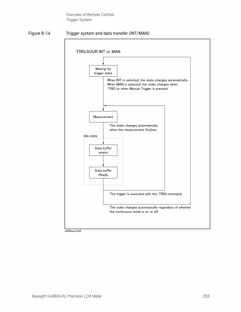
Keysight E4980A/AL Precision LCR Meter 253
Overview of Remote ControlTrigger System
Figure 8-14 Trigger system and data transfer (INT/MAN)
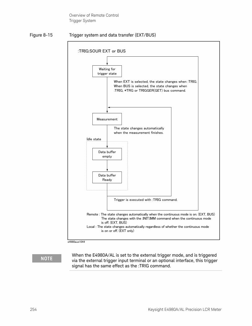
254 Keysight E4980A/AL Precision LCR Meter
Overview of Remote ControlTrigger System
8-
Figure 8-15 Trigger system and data transfer (EXT/BUS)
When the E4980A/AL is set to the external trigger mode, and is triggered via the external trigger input terminal or an optional interface, this trigger signal has the same effect as the :TRIG command.
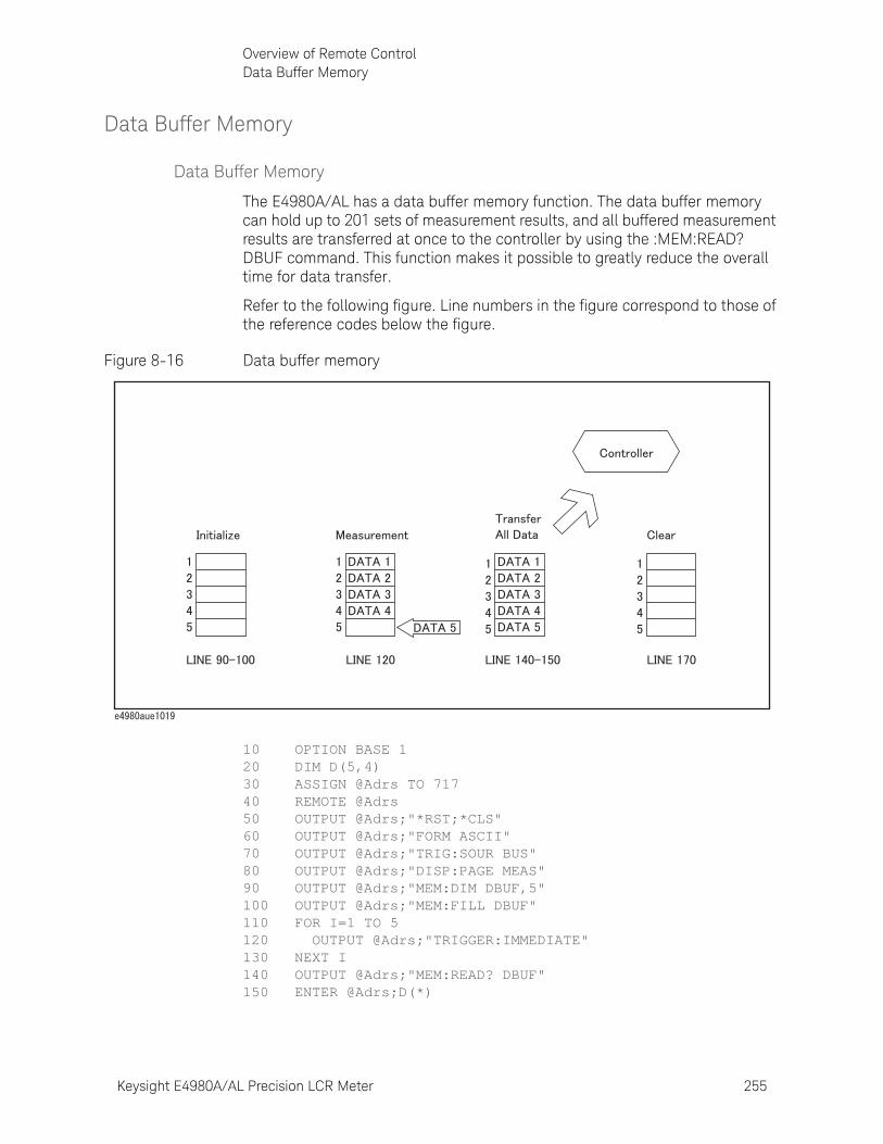
Keysight E4980A/AL Precision LCR Meter 255
Overview of Remote ControlData Buffer Memory
Data Buffer Memory
Data Buffer Memory
The E4980A/AL has a data buffer memory function. The data buffer memory can hold up to 201 sets of measurement results, and all buffered measurement results are transferred at once to the controller by using the :MEM:READ? DBUF command. This function makes it possible to greatly reduce the overall time for data transfer.
Refer to the following figure. Line numbers in the figure correspond to those of the reference codes below the figure.
Figure 8-16 Data buffer memory
10 OPTION BASE 120 DIM D(5,4)30 ASSIGN @Adrs TO 71740 REMOTE @Adrs50 OUTPUT @Adrs;"*RST;*CLS"60 OUTPUT @Adrs;"FORM ASCII"70 OUTPUT @Adrs;"TRIG:SOUR BUS"80 OUTPUT @Adrs;"DISP:PAGE MEAS"90 OUTPUT @Adrs;"MEM:DIM DBUF,5"100 OUTPUT @Adrs;"MEM:FILL DBUF"110 FOR I=1 TO 5120 OUTPUT @Adrs;"TRIGGER:IMMEDIATE"130 NEXT I140 OUTPUT @Adrs;"MEM:READ? DBUF"150 ENTER @Adrs;D(*)
256 Keysight E4980A/AL Precision LCR Meter
Overview of Remote ControlData Buffer Memory
8-
160 PRINT D(*)170 OUTPUT @Adrs;"MEM:CLE DBUF"180 END
When Data Buffer Memory is Used
Follow the rules below when using the data buffer memory function.
o Measurement data collected after sending the :MMEM:FILL DBUF command to use the data buffer memory function are stored in the data buffer memory in the order measured.
o When the E4980A/AL is triggered using the :TRIG command, the measurement results are stored only in the data buffer memory. Therefore, you do not have to clear the output buffer after each measurement.
*When the E4980A/AL is triggered using the *TRG or TRIGGER (GET) bus command, the measurement results are stored in both the data buffer memory and the output buffer. Therefore, it is necessary to read the measurement results in the output buffer using the controller and to clear the output buffer each time a measurement is made. If you fail to do this, an error (-410, “Query INTERRUPTED”) will occur.
The output buffer is the area where measurement data are stored when the E4980A/AL is triggered without using the data buffer memory. The data buffer memory is off in the E4980A/AL’s initial state, and measurement data are stored in the output buffer. It is necessary to read data in the output buffer using the controller and clear the output buffer each time a measurement is made.
o When the number of sets of measurement data exceeds the capacity of the buffer memory, all of the overflowed measurement data will be lost, an error (90, “Data Memory Overflow”) will occur, and bit 3 of the standard event status register will be set to 1. When you store new data into the buffer data memory, use the :MEM:CLE DBUF command to clear the data buffer memory.
o When the number of sets of measurement data is less than the capacity of the buffer memory, the following data, instead of the actual measurement data, are input to the unused portion of the data buffer memory.
o When the data buffer memory function is used during a list sweep measurement, the measurement result for one sweep point is stored as one set of measurement data. Therefore, when two or more sweep points are the
Data A 9.9E37
Data B 9.9E37
Status -1
BIN No. or IN/OUT 0

Keysight E4980A/AL Precision LCR Meter 257
Overview of Remote ControlData Buffer Memory
same and are adjacent, the E4980A/AL measures the device once, but the number of data sets stored in the data buffer memory is equal to that of the sweep points.
o When the list sweep measurement’s limit function is set to off at a sweep point, IN/OUT is 0. Also, when the comparator function is set to off, the BIN No. is 0.
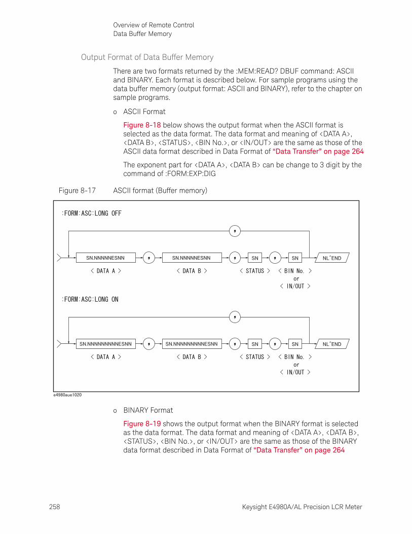
258 Keysight E4980A/AL Precision LCR Meter
Overview of Remote ControlData Buffer Memory
8-
Output Format of Data Buffer Memory
There are two formats returned by the :MEM:READ? DBUF command: ASCII and BINARY. Each format is described below. For sample programs using the data buffer memory (output format: ASCII and BINARY), refer to the chapter on sample programs.
o ASCII Format
Figure 8-18 below shows the output format when the ASCII format is selected as the data format. The data format and meaning of <DATA A>, <DATA B>, <STATUS>, <BIN No.>, or <IN/OUT> are the same as those of the ASCII data format described in Data Format of “Data Transfer” on page 264
The exponent part for <DATA A>, <DATA B> can be change to 3 digit by the command of :FORM:EXP:DIG
Figure 8-17 ASCII format (Buffer memory)
o BINARY Format
Figure 8-19 shows the output format when the BINARY format is selected as the data format. The data format and meaning of <DATA A>, <DATA B>, <STATUS>, <BIN No.>, or <IN/OUT> are the same as those of the BINARY data format described in Data Format of “Data Transfer” on page 264
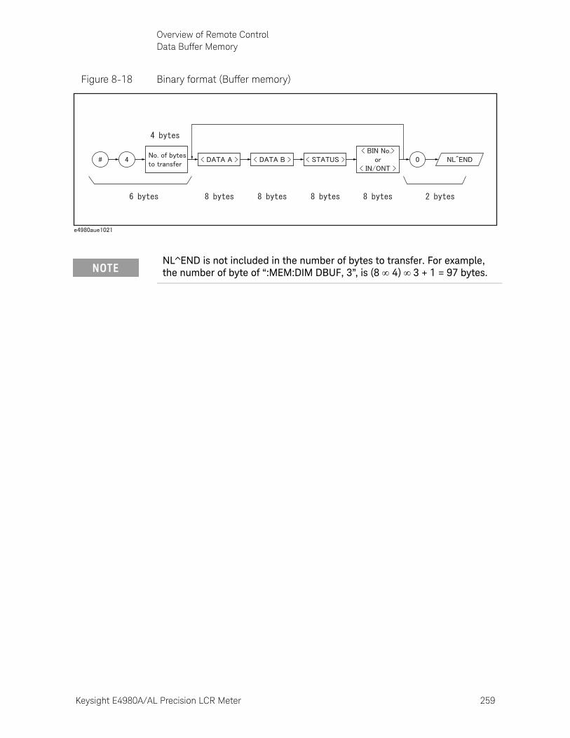
Keysight E4980A/AL Precision LCR Meter 259
Overview of Remote ControlData Buffer Memory
Figure 8-18 Binary format (Buffer memory)
NL^END is not included in the number of bytes to transfer. For example, the number of byte of “:MEM:DIM DBUF, 3”, is (8 4) 3 + 1 = 97 bytes.
260 Keysight E4980A/AL Precision LCR Meter
Overview of Remote ControlStarting a Measurement Cycle (triggering the instrument)
8-
Starting a Measurement Cycle (triggering the instrument)
Configuring the instrument to automatically perform continuous measurement
Step 1. When the trigger system does not run (“Idle” state), use the :INIT:CONT command to turn on the continuous initiation mode.
Step 2. Issue the :TRIG:SOUR command to set the trigger source to the internal trigger.
Starting Measurement on Demand
There are two ways to start measurement on demand.
Trigger the instrument to start measurement when the trigger system is in the “Waiting for Trigger” state
Put the E4980A/AL in the “Waiting for Trigger” state and start measurement whenever you want. In cases where it takes some time to obtain stable measurement values, a controller can control the timing for triggering.
Follow the steps below.
Step 1. When the trigger system is not operating (“Idle” state), use the :INIT:CONT command to turn on the continuous initiation mode.
Step 2. Issue the :TRIG:SOUR command to set the trigger source to “Bus Trigger.”
Step 3. Trigger the instrument whenever you want to perform measurement. An external controller can trigger the instrument with one of the following two commands:
Step 4. Repeat Step 3 to start the next measurement cycle.
Obtaining measurement data on demand while continuous sweep is performed
Start measurement whenever you want while the E4980A/AL performs continuous measurement.
Follow the steps below.
Step 1. When the trigger system is operating (any state other than “Idle”), abort the trigger system using the :ABOR command.
Command Applicable trigger source
*TRG Bus trigger only
:TRIG External triggerBus triggerManual trigger
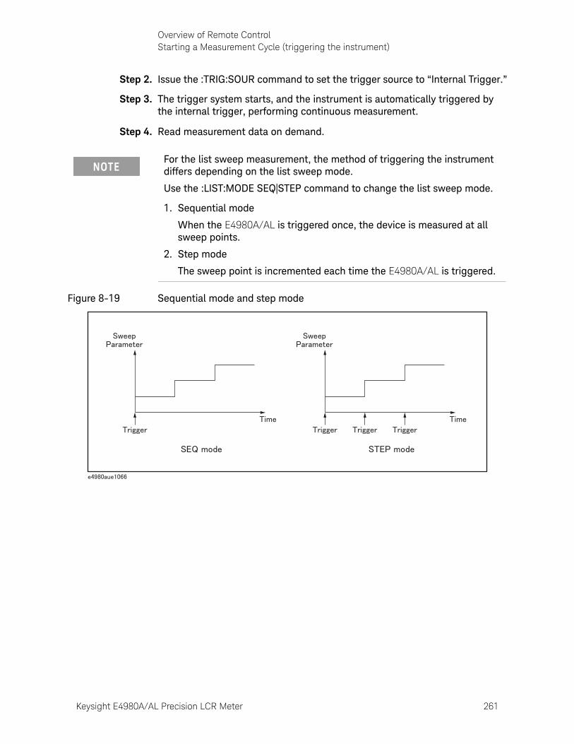
Keysight E4980A/AL Precision LCR Meter 261
Overview of Remote ControlStarting a Measurement Cycle (triggering the instrument)
Step 2. Issue the :TRIG:SOUR command to set the trigger source to “Internal Trigger.”
Step 3. The trigger system starts, and the instrument is automatically triggered by the internal trigger, performing continuous measurement.
Step 4. Read measurement data on demand.
Figure 8-19 Sequential mode and step mode
For the list sweep measurement, the method of triggering the instrument differs depending on the list sweep mode.
Use the :LIST:MODE SEQ|STEP command to change the list sweep mode.
1. Sequential mode
When the E4980A/AL is triggered once, the device is measured at all sweep points.
2. Step mode
The sweep point is incremented each time the E4980A/AL is triggered.
262 Keysight E4980A/AL Precision LCR Meter
Overview of Remote ControlWaiting for the End of Measurement
8-
Waiting for the End of Measurement
Using the status register
The E4980A/AL’s status can be detected through the status registers. This section explains how to use the status registers to detect the end of measurement. For a complete description of the status report mechanism, including the specifications of each bit, see “Status Byte” on page 270.
The measurement status is reported by the operation status event register. An SRQ (service request) is convenient for detecting the end of measurement. It uses the information reported by this register.
To detect the end of measurement via an SRQ, use one of the following commands:
• *SRE
• :STAT:OPER:ENAB
Follow these steps to use an SRQ.
Step 1. Configure the E4980A/AL so that it generates an SRQ when the operation status event register’s bit (a bit that is set to 1 during measurement) is changed from 1 to 0.
Step 2. Trigger the instrument to start a measurement cycle.
Step 3. When an SRQ is generated, the program interrupts the measurement cycle.
When the sweep averaging function is on, the E4980A/AL generates an SRQ when it has finished taking a number of measurements that is equal to the sweep averaging number.
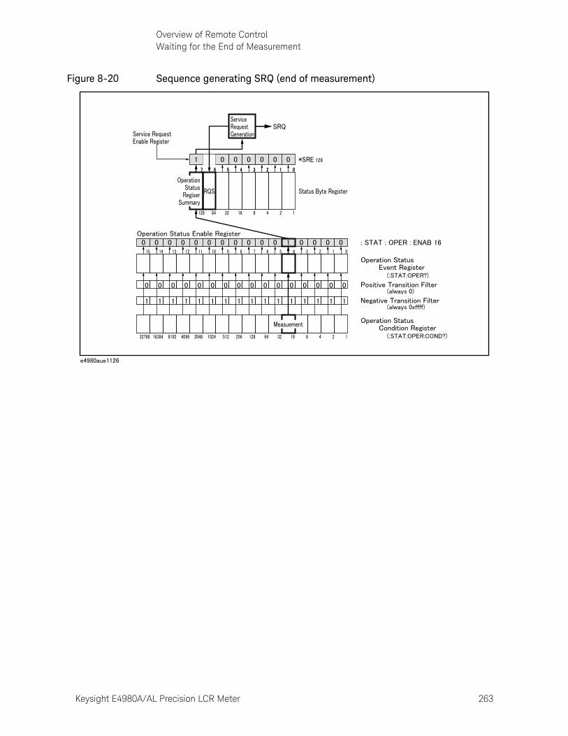
Keysight E4980A/AL Precision LCR Meter 263
Overview of Remote ControlWaiting for the End of Measurement
Figure 8-20 Sequence generating SRQ (end of measurement)

264 Keysight E4980A/AL Precision LCR Meter
Overview of Remote ControlData Transfer
8-
Data TransferThis section describes data transfer.
Data Format
The E4980A/AL offers two data formats for GPIB data transfer to the controller, ASCII and BINARY. Data transfer rates vary depending on the data format used.
ASCII Format
The ASCII data format is the default output format. When the :FORM:DATA ASC command is executed, the E4980A/AL transfers data in the ASCII format. The ASCII format of the E4980A/AL has two modes: the six-significant-digit mode and the ten-significant-digit mode. The six-significant-digit mode is the default, though the format can be switched to the ten-significant-digit mode by using the :FORM:ASC:LONG ON command. The ASCII data output format on the MEAS DISPLAY, BIN No., or BIN COUNT page is described below.
Figure 8-21 ASCII Format 1
The <DATA A>, <DATA B>, <STATUS>, and <BIN No.> formats are as follows.
• <DATA A> and <DATA B> format:
Keysight E4980A/AL Precision LCR Meter 265
Overview of Remote ControlData Transfer
The data output formats for <DATA A> (primary parameter’s measurement data), and <DATA B> (secondary parameter’s measurement data) uses the 12-ASCII character fixed-length format as follows.
The exponent part for <DATA A>, <DATA B> can be change to 3 digit by the command of :FORM:EXP:DIG
SN.NNNNNESNN (S:+/-, N: 0 to 9, E: Exponent Sign, LONG OFF)
SN.NNNNNNNNNESNN (S:+/-, N: 0 to 9, E: Exponent Sign, LONG ON)
• <STATUS> Format:
The <STATUS> data shows the status of measurement data as follows.
-1: No data (in the data buffer memory)
0: Normal measurement data
+1: Overload
+3: Signal source overloaded
+4: ALC (auto level control) unable to regulate
The data output formats for <STATUS> uses the two-ASCII character fixed-length format as follows.
SN (S:+/-, N: 0 to 4)
• <BIN No.> Format:
The <BIN No.> shows the bin sorting results as follows.
0: OUT_OF_BINS
+1 to +9: BIN 1 to BIN 9
+10: AUX_BIN
The <BIN No.> data is output with the measurement data only when the comparator function is set to on.
The data output formats for <BIN No.> uses a two- or three-ASCII character data-length format as follows.
SN or SNN (S:+/-, N: 0 to 9)
When the <STATUS> is -1 or 1, the measurement data are given as 9.9E37. When the <STATUS> is 0, 3, or 4, however, the actual measurement data are output.
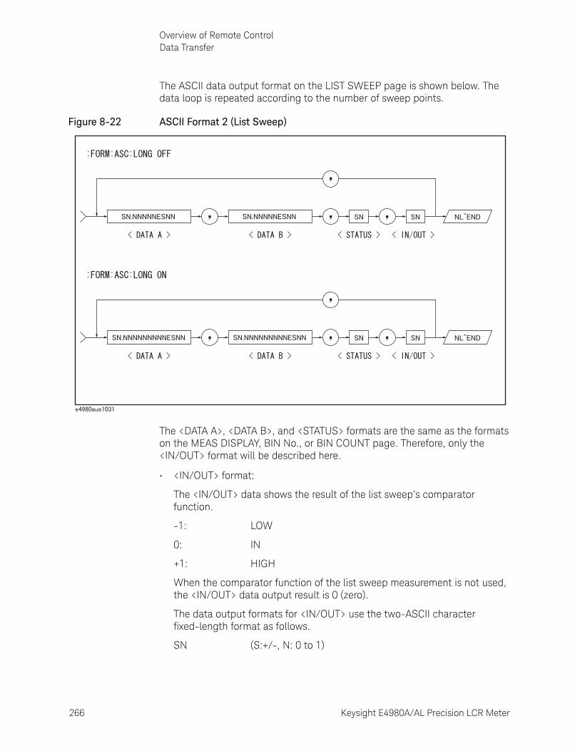
266 Keysight E4980A/AL Precision LCR Meter
Overview of Remote ControlData Transfer
8-
The ASCII data output format on the LIST SWEEP page is shown below. The data loop is repeated according to the number of sweep points.
Figure 8-22 ASCII Format 2 (List Sweep)
The <DATA A>, <DATA B>, and <STATUS> formats are the same as the formats on the MEAS DISPLAY, BIN No., or BIN COUNT page. Therefore, only the <IN/OUT> format will be described here.
• <IN/OUT> format:
The <IN/OUT> data shows the result of the list sweep’s comparator function.
-1: LOW
0: IN
+1: HIGH
When the comparator function of the list sweep measurement is not used, the <IN/OUT> data output result is 0 (zero).
The data output formats for <IN/OUT> use the two-ASCII character fixed-length format as follows.
SN (S:+/-, N: 0 to 1)
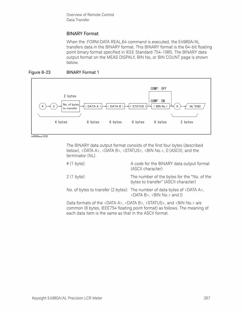
Keysight E4980A/AL Precision LCR Meter 267
Overview of Remote ControlData Transfer
BINARY Format
When the :FORM:DATA REAL,64 command is executed, the E4980A/AL transfers data in the BINARY format. This BINARY format is the 64-bit floating point binary format specified in IEEE Standard 754-1985. The BINARY data output format on the MEAS DISPALY, BIN No, or BIN COUNT page is shown below.
Figure 8-23 BINARY Format 1
The BINARY data output format consists of the first four bytes (described below), <DATA A>, <DATA B>, <STATUS>, <BIN No.>, 0 (ASCII), and the terminator (NL).
# (1 byte): A code for the BINARY data output format (ASCII character)
2 (1 byte): The number of the bytes for the “No. of the bytes to transfer” (ASCII character)
No. of bytes to transfer (2 bytes): The number of data bytes of <DATA A>, <DATA B>, <BIN No.> and 0
Data formats of the <DATA A>, <DATA B>, <STATUS>, and <BIN No.> are common (8 bytes, IEEE754 floating point format) as follows. The meaning of each data item is the same as that in the ASCII format.
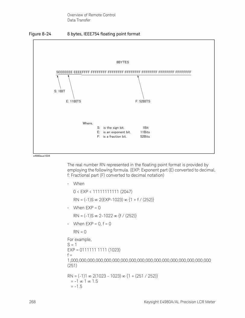
268 Keysight E4980A/AL Precision LCR Meter
Overview of Remote ControlData Transfer
8-
Figure 8-24 8 bytes, IEEE754 floating point format
The real number RN represented in the floating point format is provided by employing the following formula. (EXP: Exponent part (E) converted to decimal, f: Fractional part (F) converted to decimal notation)
• When
0 < EXP < 11111111111 (2047)
RN = (-1)S 2(EXP-1023) {1 + f / (252)}
• When EXP = 0
RN = (-1)S 2-1022 {f / (252)}
• When EXP = 0, f = 0
RN = 0
For example,S = 1EXP = 0111111 1111 (1023)f = 1,000,000,000,000,000,000,000,000,000,000,000,000,000,000,000,000,000 (251)RN = (-1)1 2(1023 - 1023) {1 + (251 / 252)} = -1 1 1.5 = -1.5
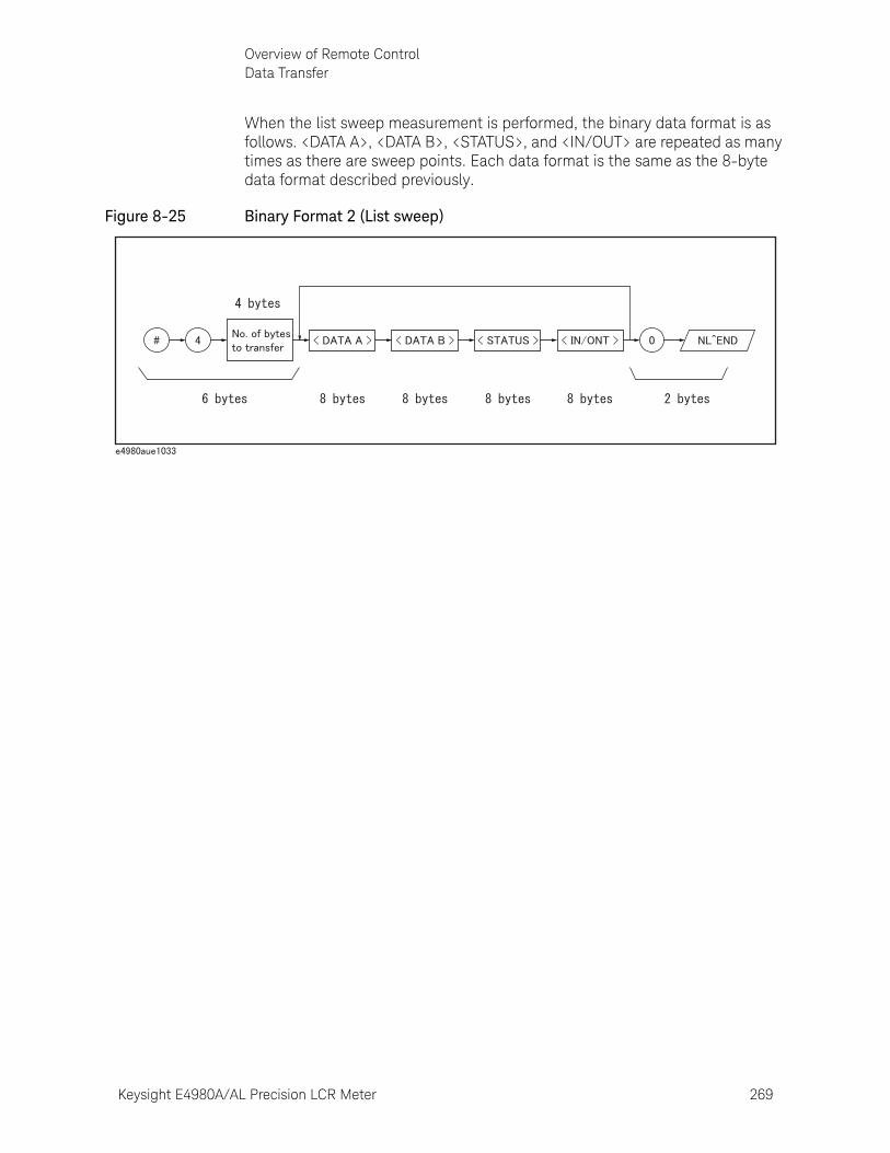
Keysight E4980A/AL Precision LCR Meter 269
Overview of Remote ControlData Transfer
When the list sweep measurement is performed, the binary data format is as follows. <DATA A>, <DATA B>, <STATUS>, and <IN/OUT> are repeated as many times as there are sweep points. Each data format is the same as the 8-byte data format described previously.
Figure 8-25 Binary Format 2 (List sweep)
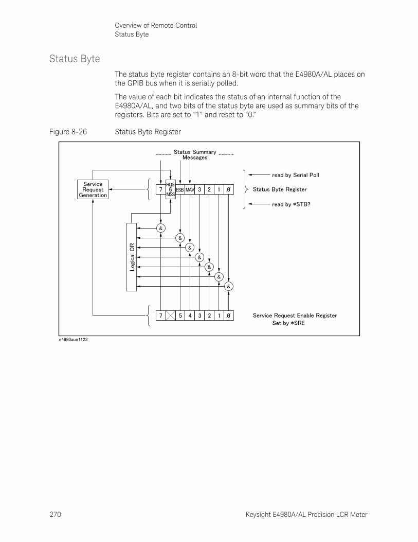
270 Keysight E4980A/AL Precision LCR Meter
Overview of Remote ControlStatus Byte
8-
Status ByteThe status byte register contains an 8-bit word that the E4980A/AL places on the GPIB bus when it is serially polled.
The value of each bit indicates the status of an internal function of the E4980A/AL, and two bits of the status byte are used as summary bits of the registers. Bits are set to “1” and reset to “0.”
Figure 8-26 Status Byte Register
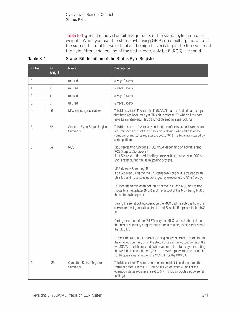
Keysight E4980A/AL Precision LCR Meter 271
Overview of Remote ControlStatus Byte
Table 8-1 gives the individual bit assignments of the status byte and its bit weights. When you read the status byte using GPIB serial polling, the value is the sum of the total bit weights of all the high bits existing at the time you read the byte. After serial polling of the status byte, only bit 6 (RQS) is cleared.
Table 8-1 Status Bit definition of the Status Byte Register
Bit No. Bit Weight
Name Description
0 1 unused always 0 (zero)
1 2 unused always 0 (zero)
2 4 unused always 0 (zero)
3 8 unused always 0 (zero)
4 16 MAV (message available) This bit is set to “1” when the E4980A/AL has available data to output that have not been read yet. This bit is reset to “0” when all the data have been retrieved. (This bit is not cleared by serial polling.)
5 32 Standard Event Status Register Summary
This bit is set to “1” when any enabled bits of the standard event status register have been set to “1.” This bit is cleared when all bits of the standard event status register are set to “0.” (This bit is not cleared by serial polling).
6 64 RQS Bit 6 serves two functions (RQS/MSS), depending on how it is read.RQS (Request Service) BitIf bit 6 is read in the serial polling process, it is treated as an RQS bit and is reset during the serial polling process.MSS (Master Summary) BitIf bit 6 is read using the *STB? (status byte) query, it is treated as an MSS bit, and its value is not changed by executing the *STB? query.To understand this operation, think of the RQS and MSS bits as two inputs to a multiplexer (MUX) and the output of the MUX being bit 6 of the status byte register.During the serial polling operation the MUX path selected is from the service request generation circuit to bit 6, so bit 6 represents the RQS bit.During execution of the *STB? query the MUX path selected is from the master summary bit generation circuit to bit 6, so bit 6 represents the MSS bit.To clear the MSS bit, all bits of the original registers corresponding to the enabled summary bit in the status byte and the output buffer of the E4980A/AL must be cleared. When you read the status byte including the MSS bit instead of the RQS bit, the *STB? query must be used. The *STB? query clears neither the MSS bit nor the RQS bit.
7 128 Operation Status Register Summary
This bit is set to “1” when one or more enabled bits of the operation status register is set to “1.” This bit is cleared when all bits of the operation status register are set to 0. (This bit is not cleared by serial polling.)
272 Keysight E4980A/AL Precision LCR Meter
Overview of Remote ControlStatus Byte
8-
Enabling the Status Byte
A service request (SRQ) will be generated when any enabled bit in the status byte register is set to “1.” Therefore, to enable/disable any bits of the status byte register, you can set bits in the service request enable register. These bits correspond to bits in the status byte register. When a bit is set in the service request enable register, it enables that bit in the status byte register to request service. To set bits in the service request enable register, the *SRE command is used. The syntax of the *SRE command is:
*SRE <n>Where, <n>: decimal number (0 to 255)
For example, If <n> is equal to 160 (10100000 in binary notation), bits 5 and 7 are enabled as follows.
In this case, when either bit 5 or bit 7 of the status byte is set to “1,” a service request is generated.
The default setting is *SRE 0 (all bits of the status byte are disabled).
Bit No. of Status Byte MSB LSB
7 6 5 4 3 2 1 0
Bit Pattern for *SRE command 1 0 1 0 0 0 0 0
Bit 6 (RQS) is non-maskable, and bits 0 to 3 are always 0 (zero). Thus, it is meaningless to mask these bits. (The *SRE command’s bit pattern for masking bit 6 is ignored, while the *SRE command’s bit pattern for masking bits 0 to 6 is accepted, but is meaningless.)
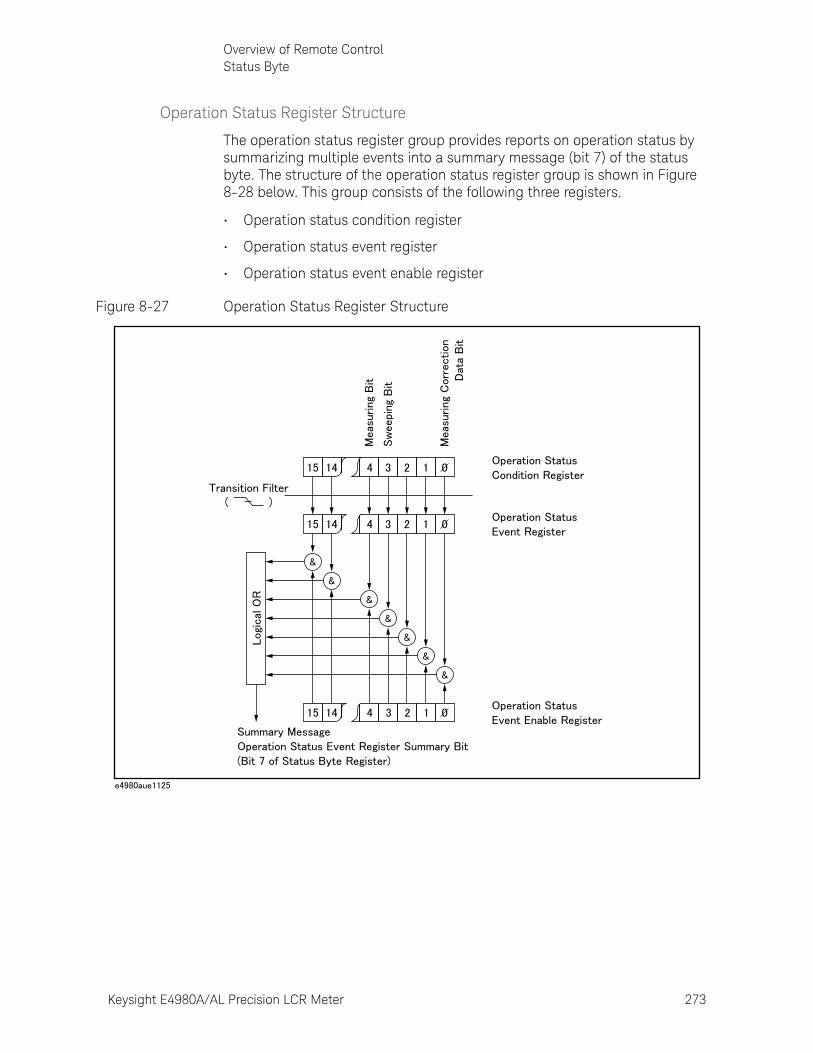
Keysight E4980A/AL Precision LCR Meter 273
Overview of Remote ControlStatus Byte
Operation Status Register Structure
The operation status register group provides reports on operation status by summarizing multiple events into a summary message (bit 7) of the status byte. The structure of the operation status register group is shown in Figure 8-28 below. This group consists of the following three registers.
• Operation status condition register
• Operation status event register
• Operation status event enable register
Figure 8-27 Operation Status Register Structure
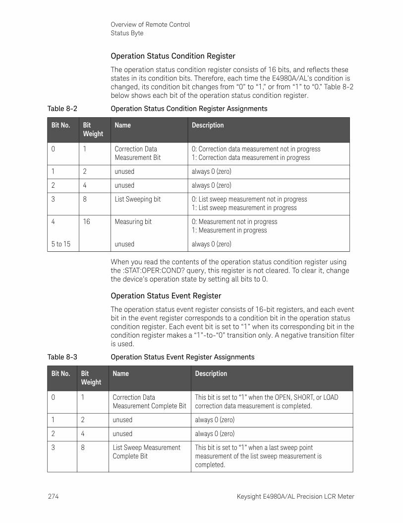
274 Keysight E4980A/AL Precision LCR Meter
Overview of Remote ControlStatus Byte
8-
Operation Status Condition Register
The operation status condition register consists of 16 bits, and reflects these states in its condition bits. Therefore, each time the E4980A/AL’s condition is changed, its condition bit changes from “0” to “1,” or from “1” to “0.” Table 8-2 below shows each bit of the operation status condition register.
When you read the contents of the operation status condition register using the :STAT:OPER:COND? query, this register is not cleared. To clear it, change the device’s operation state by setting all bits to 0.
Operation Status Event Register
The operation status event register consists of 16-bit registers, and each event bit in the event register corresponds to a condition bit in the operation status condition register. Each event bit is set to “1” when its corresponding bit in the condition register makes a “1”-to-“0” transition only. A negative transition filter is used.
Table 8-2 Operation Status Condition Register Assignments
Bit No. Bit Weight
Name Description
0 1 Correction Data Measurement Bit
0: Correction data measurement not in progress1: Correction data measurement in progress
1 2 unused always 0 (zero)
2 4 unused always 0 (zero)
3 8 List Sweeping bit 0: List sweep measurement not in progress1: List sweep measurement in progress
4 16 Measuring bit 0: Measurement not in progress1: Measurement in progress
5 to 15 unused always 0 (zero)
Table 8-3 Operation Status Event Register Assignments
Bit No. Bit Weight
Name Description
0 1 Correction Data Measurement Complete Bit
This bit is set to “1” when the OPEN, SHORT, or LOAD correction data measurement is completed.
1 2 unused always 0 (zero)
2 4 unused always 0 (zero)
3 8 List Sweep Measurement Complete Bit
This bit is set to “1” when a last sweep point measurement of the list sweep measurement is completed.
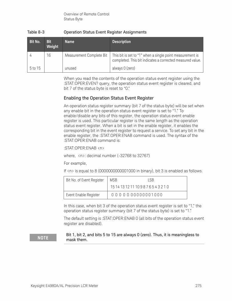
Keysight E4980A/AL Precision LCR Meter 275
Overview of Remote ControlStatus Byte
When you read the contents of the operation status event register using the :STAT:OPER:EVEN? query, the operation status event register is cleared, and bit 7 of the status byte is reset to “0.”
Enabling the Operation Status Event Register
An operation status register summary (bit 7 of the status byte) will be set when any enable bit in the operation status event register is set to “1.” To enable/disable any bits of this register, the operation status event enable register is used. This particular register is the same length as the operation status event register. When a bit is set in the enable register, it enables the corresponding bit in the event register to request a service. To set any bit in the enable register, the :STAT:OPER:ENAB command is used. The syntax of the :STAT:OPER:ENAB command is:
:STAT:OPER:ENAB <n>
where, <n>: decimal number (-32768 to 32767)
For example,
If <n> is equal to 8 (0000000000001000 in binary), bit 3 is enabled as follows.
In this case, when bit 3 of the operation status event register is set to “1,” the operation status register summary (bit 7 of the status byte) is set to “1.”
The default setting is :STAT:OPER:ENAB 0 (all bits of the operation status event register are disabled).
4 16 Measurement Complete Bit This bit is set to “1” when a single point measurement is completed. This bit indicates a corrected measured value.
5 to 15 unused always 0 (zero)
Table 8-3 Operation Status Event Register Assignments
Bit No. Bit Weight
Name Description
Bit No. of Event Register MSB LSB
15 14 13 12 11 10 9 8 7 6 5 4 3 2 1 0
Event Enable Register 0 0 0 0 0 0 0 0 0 0 0 0 1 0 0 0
Bit 1, bit 2, and bits 5 to 15 are always 0 (zero). Thus, it is meaningless to mask them.

276 Keysight E4980A/AL Precision LCR Meter
Overview of Remote ControlStatus Byte
8-
Standard Event Status Register
The standard event status register consists of 8 bits as shown in Table 8-4 and is defined in IEEE 488.2-1987. If one or more enable bits of the standard event status register is set to “1,” bit 5 (standard event status register summary) of the status byte is set to “1.”
When each error bit (bits 2, 3, 4, and 5) of the standard event status register is set to “1,” an error message with the following error numbers is input to the error queue.
When you read the contents of the standard event status register using the *ESR? query command, the standard event status register is cleared, and bit 5 of the status byte is reset to “0.”
Bit No. Error No.
2 (query error) -400 to -499
3 (Device specific error) 0 to 32,767, -300 to -399
4 (Execution error) -200 to -299
5 (Command error) -100 to -199
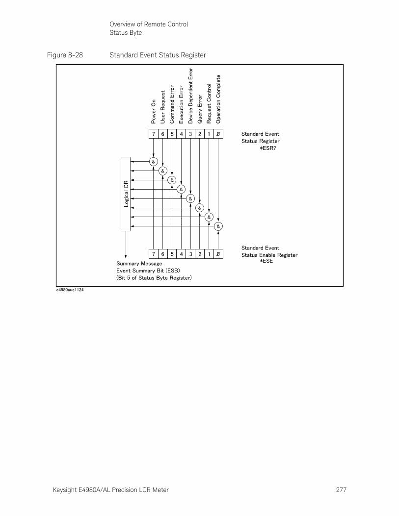
Keysight E4980A/AL Precision LCR Meter 277
Overview of Remote ControlStatus Byte
Figure 8-28 Standard Event Status Register

278 Keysight E4980A/AL Precision LCR Meter
Overview of Remote ControlStatus Byte
8-
Table 8-4 Standard Event Status Register Assignments
Bit No.
Bit Weight
Name Description
0 1 Operation Complete (OPC) Bit
This bit is set to “1” when the E4980A/AL has completed all selected pending operations before sending the *OPC command.
1 2 Request Control (RQC) Bit always 0 (zero)
2 4 Query Error (QYE) Bit This bit is set to “1” when reading data from the output buffer and no data was present, or when the data was lost.
3 8 Device specific error (DDE) Bit
This bit is set to “1” when a device-dependent error (except for the command error, query error, and execution error) has occurred.
4 16 Execution Error (EXE) Bit This bit is set to “1” when a parameter following a header of the GPIB command was evaluated by the E4980A/AL as being outside its legal input range or is otherwise inconsistent with the E4980A/AL’s capabilities.
5 32 Command Error (CME) Bit This bit is set to “1” if the following command errors occur.
• IEEE 488.2 syntax error
• The device received a TRIGGER (GET) bus command inside a program message.
6 64 User Request (URQ) Bit always 0 (zero)
7 128 Power On (PON) Bit This bit is set to “1” when the E4980A/AL’s power supply has been turned off and then on since the last time this register was read.
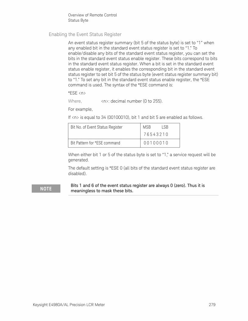
Keysight E4980A/AL Precision LCR Meter 279
Overview of Remote ControlStatus Byte
Enabling the Event Status Register
An event status register summary (bit 5 of the status byte) is set to “1” when any enabled bit in the standard event status register is set to “1.” To enable/disable any bits of the standard event status register, you can set the bits in the standard event status enable register. These bits correspond to bits in the standard event status register. When a bit is set in the standard event status enable register, it enables the corresponding bit in the standard event status register to set bit 5 of the status byte (event status register summary bit) to “1.” To set any bit in the standard event status enable register, the *ESE command is used. The syntax of the *ESE command is:
*ESE <n>
Where, <n>: decimal number (0 to 255).
For example,
If <n> is equal to 34 (00100010), bit 1 and bit 5 are enabled as follows.
When either bit 1 or 5 of the status byte is set to “1,” a service request will be generated.
The default setting is *ESE 0 (all bits of the standard event status register are disabled).
Bit No. of Event Status Register MSB LSB
7 6 5 4 3 2 1 0
Bit Pattern for *ESE command 0 0 1 0 0 0 1 0
Bits 1 and 6 of the event status register are always 0 (zero). Thus it is meaningless to mask these bits.

280 Keysight E4980A/AL Precision LCR Meter
Overview of Remote ControlStatus Byte
8-
281
Keysight E4980A/AL Precision LCR Meter
User’s Guide
9 Sample Program
This chapter describes sample programs of the E4980A/AL. The programs are written in VBA macro.
Set Up Measurement Conditions and LCD DisplayThis application program sets the measurement conditions and the LCD display of the E4980A/AL.
The program of Example 9-1 is described in detail below. Each explanation below is inserted as a comment line in the program. For details on the VISA functions, refer to the I/O Library Suite manual.
Configuration Assigns variables and enables error handling by the subroutine named ErrorHandler
Open Instrument Assigns a USB address or GPIB address to the I/O bus.
Setup Start Sets the measurement conditions and the LCD display.
Setup End Closes the I/O bus.
ErrorProc Displays an error number when an error occurs.
ErrorCheck A subroutine to check whether an error occurs when the I/O Library Suite function is executed.
SelectLCR A subroutine to change assignment of the I/O bus and address setting according to the selection of a drop down list in the B3 cell of the “Control Panel” sheet.
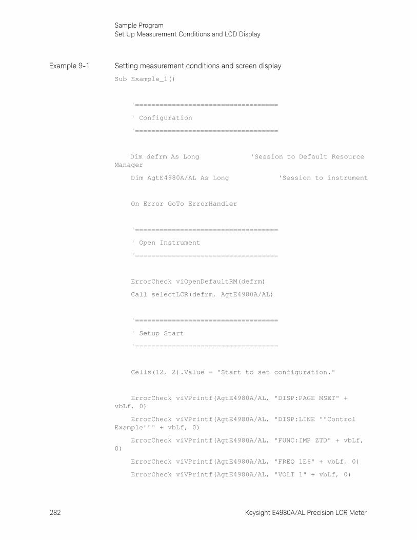
282 Keysight E4980A/AL Precision LCR Meter
Sample ProgramSet Up Measurement Conditions and LCD Display
9-
Example 9-1 Setting measurement conditions and screen display
Sub Example_1()
'===================================
' Configuration
'===================================
Dim defrm As Long 'Session to Default Resource Manager
Dim AgtE4980A/AL As Long 'Session to instrument
On Error GoTo ErrorHandler
'===================================
' Open Instrument
'===================================
ErrorCheck viOpenDefaultRM(defrm)
Call selectLCR(defrm, AgtE4980A/AL)
'===================================
' Setup Start
'===================================
Cells(12, 2).Value = "Start to set configuration."
ErrorCheck viVPrintf(AgtE4980A/AL, "DISP:PAGE MSET" + vbLf, 0)
ErrorCheck viVPrintf(AgtE4980A/AL, "DISP:LINE ""Control Example""" + vbLf, 0)
ErrorCheck viVPrintf(AgtE4980A/AL, "FUNC:IMP ZTD" + vbLf, 0)
ErrorCheck viVPrintf(AgtE4980A/AL, "FREQ 1E6" + vbLf, 0)
ErrorCheck viVPrintf(AgtE4980A/AL, "VOLT 1" + vbLf, 0)
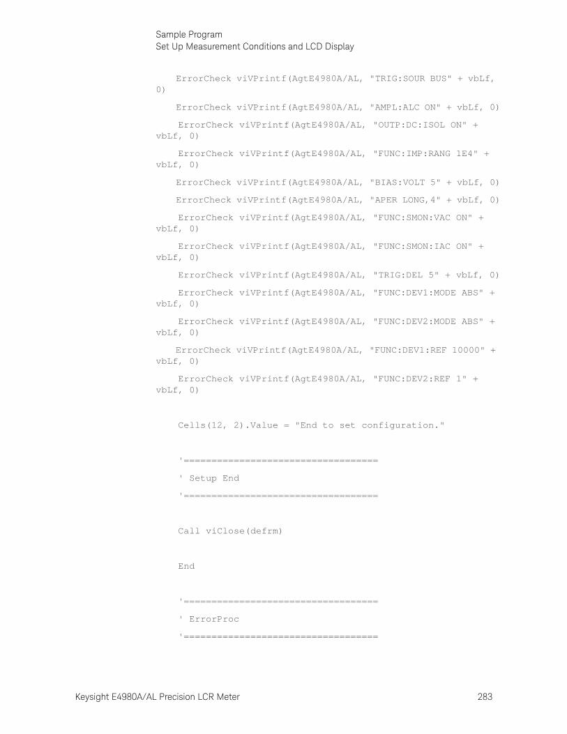
Keysight E4980A/AL Precision LCR Meter 283
Sample ProgramSet Up Measurement Conditions and LCD Display
ErrorCheck viVPrintf(AgtE4980A/AL, "TRIG:SOUR BUS" + vbLf, 0)
ErrorCheck viVPrintf(AgtE4980A/AL, "AMPL:ALC ON" + vbLf, 0)
ErrorCheck viVPrintf(AgtE4980A/AL, "OUTP:DC:ISOL ON" + vbLf, 0)
ErrorCheck viVPrintf(AgtE4980A/AL, "FUNC:IMP:RANG 1E4" + vbLf, 0)
ErrorCheck viVPrintf(AgtE4980A/AL, "BIAS:VOLT 5" + vbLf, 0)
ErrorCheck viVPrintf(AgtE4980A/AL, "APER LONG,4" + vbLf, 0)
ErrorCheck viVPrintf(AgtE4980A/AL, "FUNC:SMON:VAC ON" + vbLf, 0)
ErrorCheck viVPrintf(AgtE4980A/AL, "FUNC:SMON:IAC ON" + vbLf, 0)
ErrorCheck viVPrintf(AgtE4980A/AL, "TRIG:DEL 5" + vbLf, 0)
ErrorCheck viVPrintf(AgtE4980A/AL, "FUNC:DEV1:MODE ABS" + vbLf, 0)
ErrorCheck viVPrintf(AgtE4980A/AL, "FUNC:DEV2:MODE ABS" + vbLf, 0)
ErrorCheck viVPrintf(AgtE4980A/AL, "FUNC:DEV1:REF 10000" + vbLf, 0)
ErrorCheck viVPrintf(AgtE4980A/AL, "FUNC:DEV2:REF 1" + vbLf, 0)
Cells(12, 2).Value = "End to set configuration."
'===================================
' Setup End
'===================================
Call viClose(defrm)
End
'===================================
' ErrorProc
'===================================
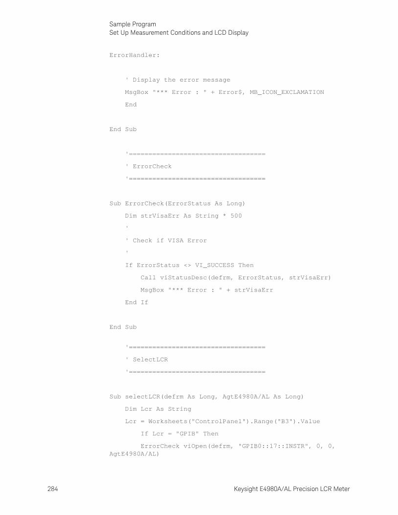
284 Keysight E4980A/AL Precision LCR Meter
Sample ProgramSet Up Measurement Conditions and LCD Display
9-
ErrorHandler:
' Display the error message
MsgBox "*** Error : " + Error$, MB_ICON_EXCLAMATION
End
End Sub
'===================================
' ErrorCheck
'===================================
Sub ErrorCheck(ErrorStatus As Long)
Dim strVisaErr As String * 500
'
' Check if VISA Error
'
If ErrorStatus <> VI_SUCCESS Then
Call viStatusDesc(defrm, ErrorStatus, strVisaErr)
MsgBox "*** Error : " + strVisaErr
End If
End Sub
'===================================
' SelectLCR
'===================================
Sub selectLCR(defrm As Long, AgtE4980A/AL As Long)
Dim Lcr As String
Lcr = Worksheets("ControlPanel").Range("B3").Value
If Lcr = "GPIB" Then
ErrorCheck viOpen(defrm, "GPIB0::17::INSTR", 0, 0, AgtE4980A/AL)

Keysight E4980A/AL Precision LCR Meter 285
Sample ProgramSet Up Measurement Conditions and LCD Display
End If
If Lcr = "USB" Then
ErrorCheck viOpen(defrm, "USB0::2391::2313::MY12345678::0::INSTR", 0, 0, AgtE4980A/AL)
End If
End Sub

286 Keysight E4980A/AL Precision LCR Meter
Sample ProgramDetecting End of Measurement
9-
Detecting End of MeasurementThis application program detects the end of measurement with the status byte after the E4980A/AL is triggered.
The program of Example 9-2 is described in detail below.
Configuration Assigns variables and enables error handling by the subroutine named ErrorHandler.
Open Instrument Assigns a USB address or GPIB address to the I/O bus. Also sets the attribute for timeout processing.
Setup Start Sets the trigger and status byte.
STB Check Waits until the status byte becomes 192. Displays the status byte while waiting and again after processing.
Setup End Closes the I/O bus.
ErrorProc Displays an error number when an error occurs.
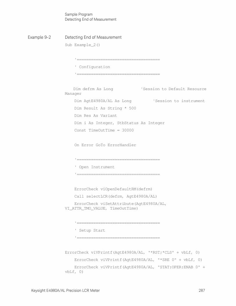
Keysight E4980A/AL Precision LCR Meter 287
Sample ProgramDetecting End of Measurement
Example 9-2 Detecting End of Measurement
Sub Example_2()
'===================================
' Configuration
'===================================
Dim defrm As Long 'Session to Default Resource Manager
Dim AgtE4980A/AL As Long 'Session to instrument
Dim Result As String * 500
Dim Res As Variant
Dim i As Integer, StbStatus As Integer
Const TimeOutTime = 30000
On Error GoTo ErrorHandler
'===================================
' Open Instrument
'===================================
ErrorCheck viOpenDefaultRM(defrm)
Call selectLCR(defrm, AgtE4980A/AL)
ErrorCheck viSetAttribute(AgtE4980A/AL, VI_ATTR_TMO_VALUE, TimeOutTime)
'===================================
' Setup Start
'===================================
ErrorCheck viVPrintf(AgtE4980A/AL, "*RST;*CLS" + vbLf, 0)
ErrorCheck viVPrintf(AgtE4980A/AL, "*SRE 0" + vbLf, 0)
ErrorCheck viVPrintf(AgtE4980A/AL, "STAT:OPER:ENAB 0" + vbLf, 0)
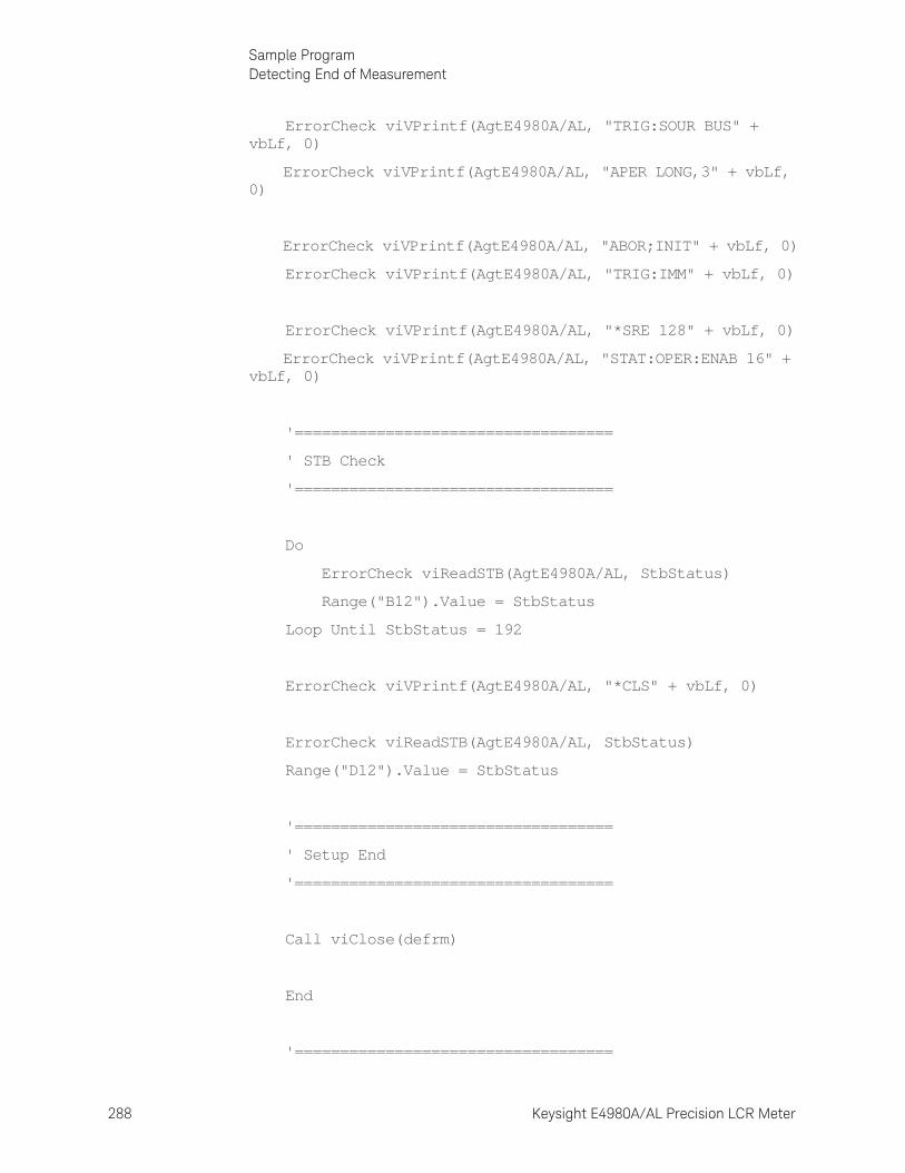
288 Keysight E4980A/AL Precision LCR Meter
Sample ProgramDetecting End of Measurement
9-
ErrorCheck viVPrintf(AgtE4980A/AL, "TRIG:SOUR BUS" + vbLf, 0)
ErrorCheck viVPrintf(AgtE4980A/AL, "APER LONG,3" + vbLf, 0)
ErrorCheck viVPrintf(AgtE4980A/AL, "ABOR;INIT" + vbLf, 0)
ErrorCheck viVPrintf(AgtE4980A/AL, "TRIG:IMM" + vbLf, 0)
ErrorCheck viVPrintf(AgtE4980A/AL, "*SRE 128" + vbLf, 0)
ErrorCheck viVPrintf(AgtE4980A/AL, "STAT:OPER:ENAB 16" + vbLf, 0)
'===================================
' STB Check
'===================================
Do
ErrorCheck viReadSTB(AgtE4980A/AL, StbStatus)
Range("B12").Value = StbStatus
Loop Until StbStatus = 192
ErrorCheck viVPrintf(AgtE4980A/AL, "*CLS" + vbLf, 0)
ErrorCheck viReadSTB(AgtE4980A/AL, StbStatus)
Range("D12").Value = StbStatus
'===================================
' Setup End
'===================================
Call viClose(defrm)
End
'===================================
Keysight E4980A/AL Precision LCR Meter 289
Sample ProgramDetecting End of Measurement
' ErrorProc
'===================================
ErrorHandler:
' Display the error message
MsgBox "*** Error : " + Error$, MB_ICON_EXCLAMATION
End
End Sub
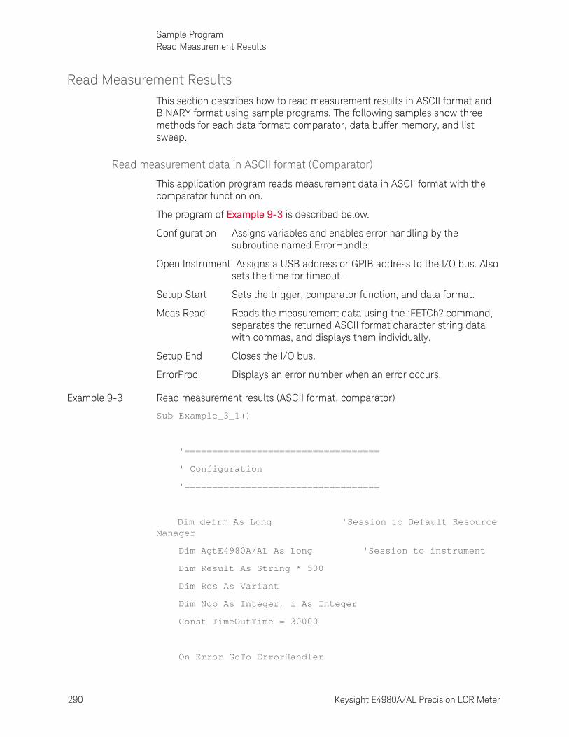
290 Keysight E4980A/AL Precision LCR Meter
Sample ProgramRead Measurement Results
9-
Read Measurement ResultsThis section describes how to read measurement results in ASCII format and BINARY format using sample programs. The following samples show three methods for each data format: comparator, data buffer memory, and list sweep.
Read measurement data in ASCII format (Comparator)
This application program reads measurement data in ASCII format with the comparator function on.
The program of Example 9-3 is described below.
Configuration Assigns variables and enables error handling by the subroutine named ErrorHandle.
Open Instrument Assigns a USB address or GPIB address to the I/O bus. Also sets the time for timeout.
Setup Start Sets the trigger, comparator function, and data format.
Meas Read Reads the measurement data using the :FETCh? command, separates the returned ASCII format character string data with commas, and displays them individually.
Setup End Closes the I/O bus.
ErrorProc Displays an error number when an error occurs.
Example 9-3 Read measurement results (ASCII format, comparator)
Sub Example_3_1()
'===================================
' Configuration
'===================================
Dim defrm As Long 'Session to Default Resource Manager
Dim AgtE4980A/AL As Long 'Session to instrument
Dim Result As String * 500
Dim Res As Variant
Dim Nop As Integer, i As Integer
Const TimeOutTime = 30000
On Error GoTo ErrorHandler
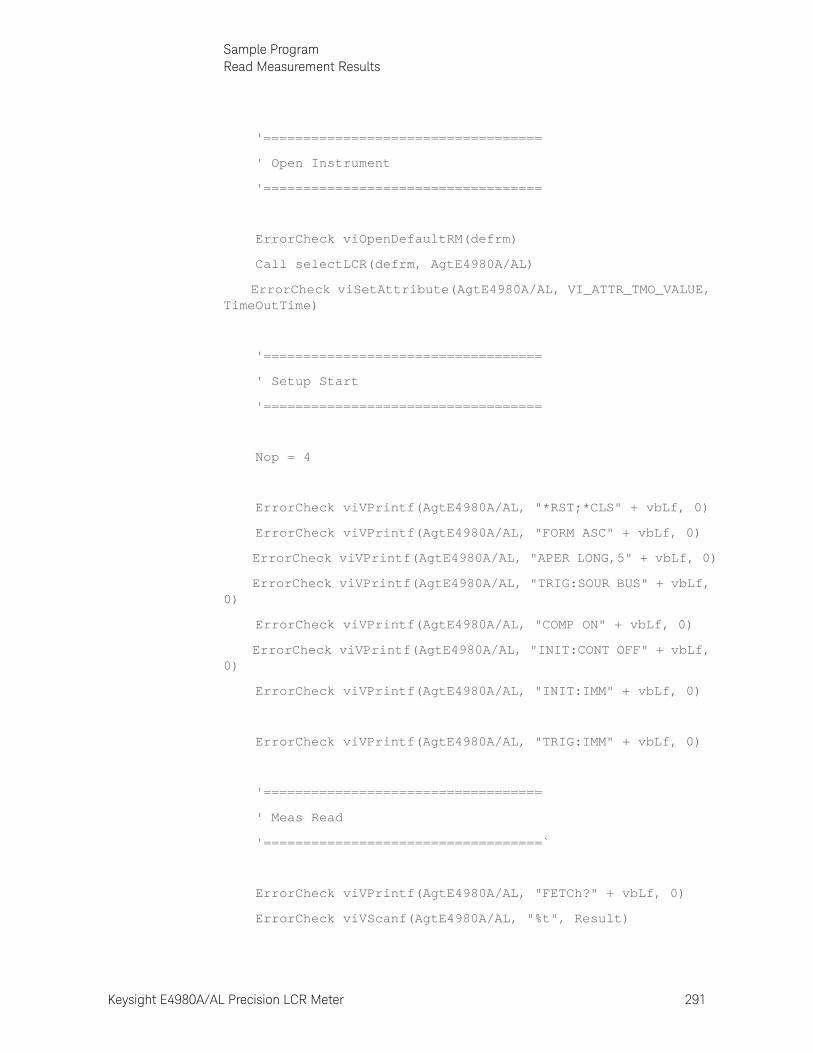
Keysight E4980A/AL Precision LCR Meter 291
Sample ProgramRead Measurement Results
'===================================
' Open Instrument
'===================================
ErrorCheck viOpenDefaultRM(defrm)
Call selectLCR(defrm, AgtE4980A/AL)
ErrorCheck viSetAttribute(AgtE4980A/AL, VI_ATTR_TMO_VALUE, TimeOutTime)
'===================================
' Setup Start
'===================================
Nop = 4
ErrorCheck viVPrintf(AgtE4980A/AL, "*RST;*CLS" + vbLf, 0)
ErrorCheck viVPrintf(AgtE4980A/AL, "FORM ASC" + vbLf, 0)
ErrorCheck viVPrintf(AgtE4980A/AL, "APER LONG,5" + vbLf, 0)
ErrorCheck viVPrintf(AgtE4980A/AL, "TRIG:SOUR BUS" + vbLf, 0)
ErrorCheck viVPrintf(AgtE4980A/AL, "COMP ON" + vbLf, 0)
ErrorCheck viVPrintf(AgtE4980A/AL, "INIT:CONT OFF" + vbLf, 0)
ErrorCheck viVPrintf(AgtE4980A/AL, "INIT:IMM" + vbLf, 0)
ErrorCheck viVPrintf(AgtE4980A/AL, "TRIG:IMM" + vbLf, 0)
'===================================
' Meas Read
'===================================`
ErrorCheck viVPrintf(AgtE4980A/AL, "FETCh?" + vbLf, 0)
ErrorCheck viVScanf(AgtE4980A/AL, "%t", Result)
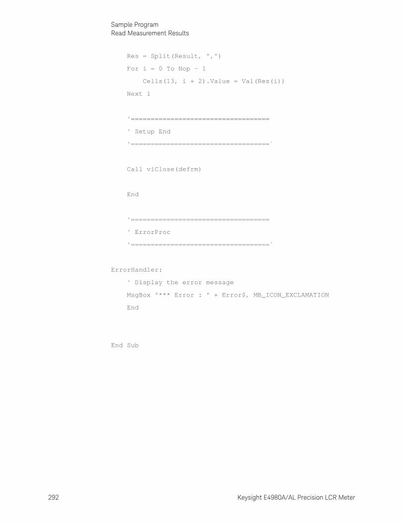
292 Keysight E4980A/AL Precision LCR Meter
Sample ProgramRead Measurement Results
9-
Res = Split(Result, ",")
For i = 0 To Nop - 1
Cells(13, i + 2).Value = Val(Res(i))
Next i
'===================================
' Setup End
'===================================`
Call viClose(defrm)
End
'===================================
' ErrorProc
'===================================`
ErrorHandler:
' Display the error message
MsgBox "*** Error : " + Error$, MB_ICON_EXCLAMATION
End
End Sub
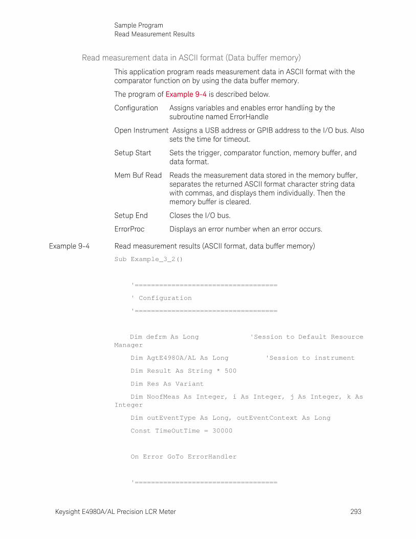
Keysight E4980A/AL Precision LCR Meter 293
Sample ProgramRead Measurement Results
Read measurement data in ASCII format (Data buffer memory)
This application program reads measurement data in ASCII format with the comparator function on by using the data buffer memory.
The program of Example 9-4 is described below.
Configuration Assigns variables and enables error handling by the subroutine named ErrorHandle
Open Instrument Assigns a USB address or GPIB address to the I/O bus. Also sets the time for timeout.
Setup Start Sets the trigger, comparator function, memory buffer, and data format.
Mem Buf Read Reads the measurement data stored in the memory buffer, separates the returned ASCII format character string data with commas, and displays them individually. Then the memory buffer is cleared.
Setup End Closes the I/O bus.
ErrorProc Displays an error number when an error occurs.
Example 9-4 Read measurement results (ASCII format, data buffer memory)
Sub Example_3_2()
'===================================
' Configuration
'===================================
Dim defrm As Long 'Session to Default Resource Manager
Dim AgtE4980A/AL As Long 'Session to instrument
Dim Result As String * 500
Dim Res As Variant
Dim NoofMeas As Integer, i As Integer, j As Integer, k As Integer
Dim outEventType As Long, outEventContext As Long
Const TimeOutTime = 30000
On Error GoTo ErrorHandler
'===================================
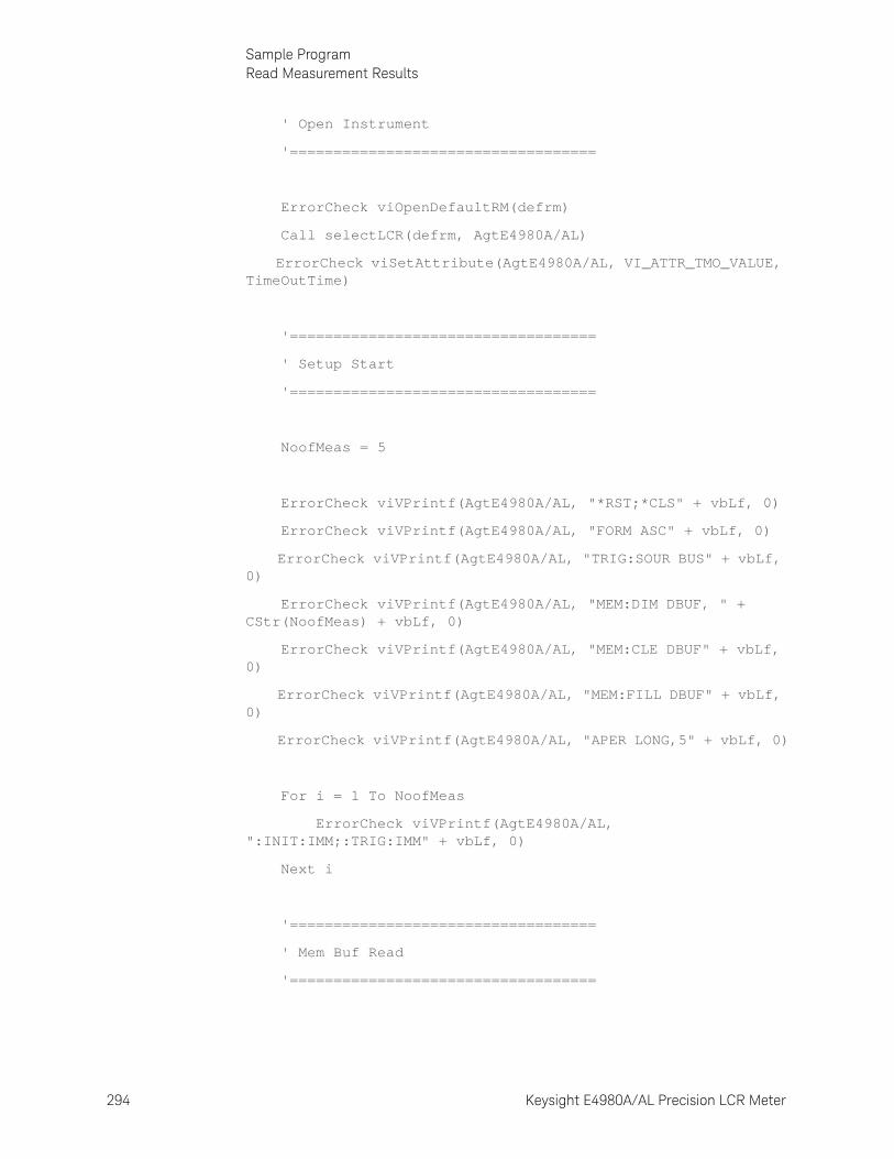
294 Keysight E4980A/AL Precision LCR Meter
Sample ProgramRead Measurement Results
9-
' Open Instrument
'===================================
ErrorCheck viOpenDefaultRM(defrm)
Call selectLCR(defrm, AgtE4980A/AL)
ErrorCheck viSetAttribute(AgtE4980A/AL, VI_ATTR_TMO_VALUE, TimeOutTime)
'===================================
' Setup Start
'===================================
NoofMeas = 5
ErrorCheck viVPrintf(AgtE4980A/AL, "*RST;*CLS" + vbLf, 0)
ErrorCheck viVPrintf(AgtE4980A/AL, "FORM ASC" + vbLf, 0)
ErrorCheck viVPrintf(AgtE4980A/AL, "TRIG:SOUR BUS" + vbLf, 0)
ErrorCheck viVPrintf(AgtE4980A/AL, "MEM:DIM DBUF, " + CStr(NoofMeas) + vbLf, 0)
ErrorCheck viVPrintf(AgtE4980A/AL, "MEM:CLE DBUF" + vbLf, 0)
ErrorCheck viVPrintf(AgtE4980A/AL, "MEM:FILL DBUF" + vbLf, 0)
ErrorCheck viVPrintf(AgtE4980A/AL, "APER LONG,5" + vbLf, 0)
For i = 1 To NoofMeas
ErrorCheck viVPrintf(AgtE4980A/AL, ":INIT:IMM;:TRIG:IMM" + vbLf, 0)
Next i
'===================================
' Mem Buf Read
'===================================
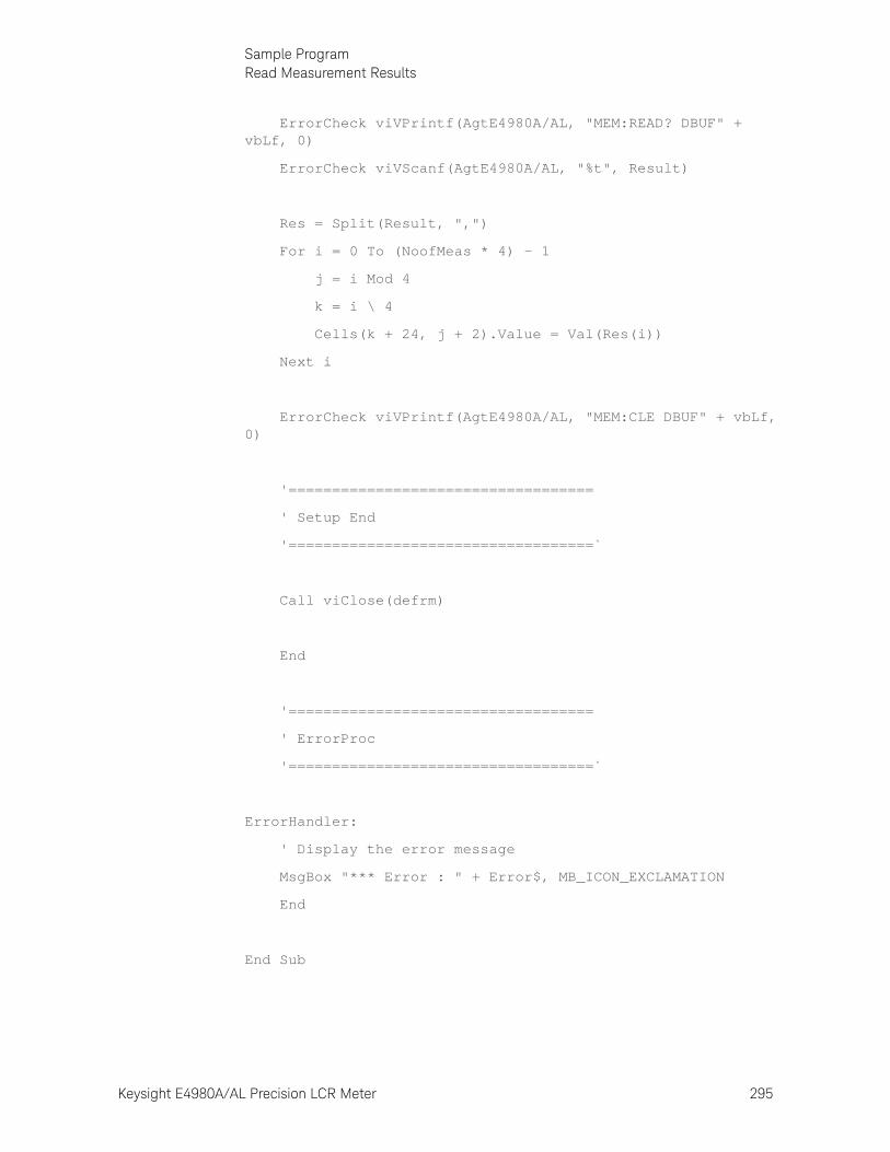
Keysight E4980A/AL Precision LCR Meter 295
Sample ProgramRead Measurement Results
ErrorCheck viVPrintf(AgtE4980A/AL, "MEM:READ? DBUF" + vbLf, 0)
ErrorCheck viVScanf(AgtE4980A/AL, "%t", Result)
Res = Split(Result, ",")
For i = 0 To (NoofMeas * 4) - 1
j = i Mod 4
k = i \ 4
Cells(k + 24, j + 2).Value = Val(Res(i))
Next i
ErrorCheck viVPrintf(AgtE4980A/AL, "MEM:CLE DBUF" + vbLf, 0)
'===================================
' Setup End
'===================================`
Call viClose(defrm)
End
'===================================
' ErrorProc
'===================================`
ErrorHandler:
' Display the error message
MsgBox "*** Error : " + Error$, MB_ICON_EXCLAMATION
End
End Sub
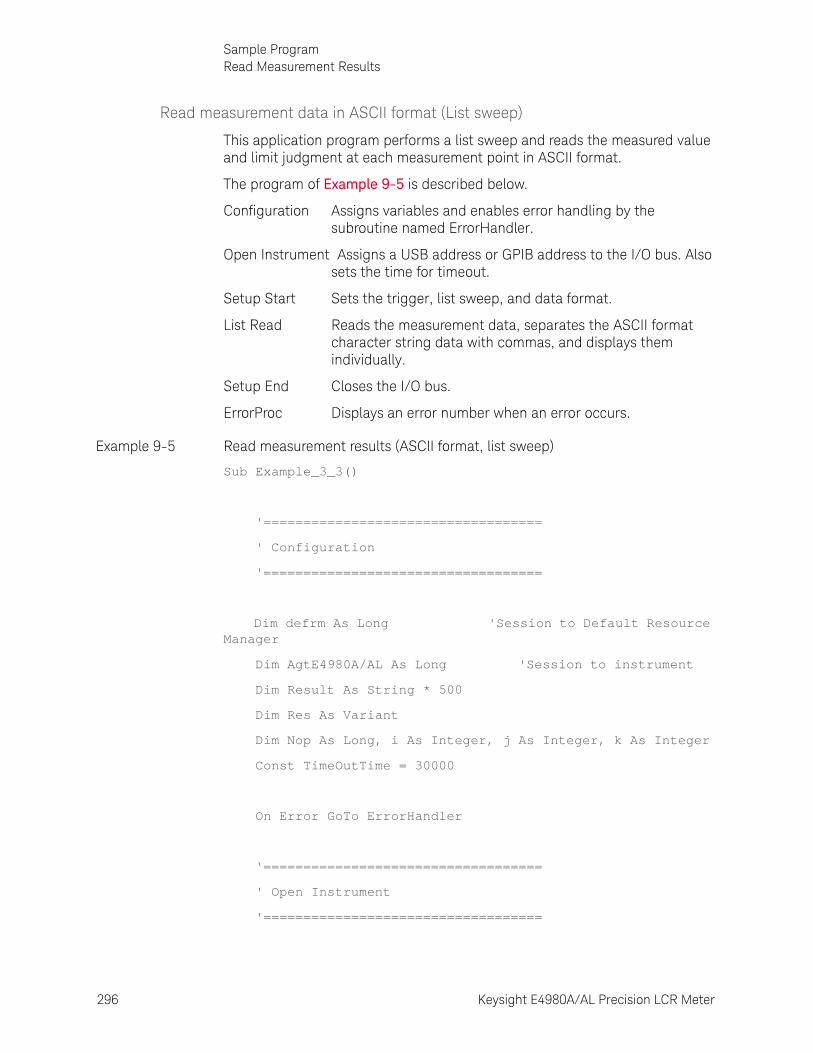
296 Keysight E4980A/AL Precision LCR Meter
Sample ProgramRead Measurement Results
9-
Read measurement data in ASCII format (List sweep)
This application program performs a list sweep and reads the measured value and limit judgment at each measurement point in ASCII format.
The program of Example 9-5 is described below.
Configuration Assigns variables and enables error handling by the subroutine named ErrorHandler.
Open Instrument Assigns a USB address or GPIB address to the I/O bus. Also sets the time for timeout.
Setup Start Sets the trigger, list sweep, and data format.
List Read Reads the measurement data, separates the ASCII format character string data with commas, and displays them individually.
Setup End Closes the I/O bus.
ErrorProc Displays an error number when an error occurs.
Example 9-5 Read measurement results (ASCII format, list sweep)
Sub Example_3_3()
'===================================
' Configuration
'===================================
Dim defrm As Long 'Session to Default Resource Manager
Dim AgtE4980A/AL As Long 'Session to instrument
Dim Result As String * 500
Dim Res As Variant
Dim Nop As Long, i As Integer, j As Integer, k As Integer
Const TimeOutTime = 30000
On Error GoTo ErrorHandler
'===================================
' Open Instrument
'===================================
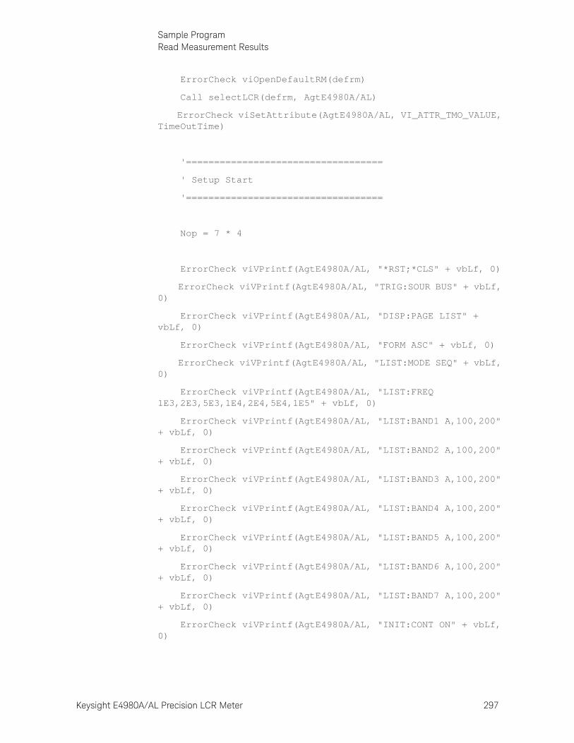
Keysight E4980A/AL Precision LCR Meter 297
Sample ProgramRead Measurement Results
ErrorCheck viOpenDefaultRM(defrm)
Call selectLCR(defrm, AgtE4980A/AL)
ErrorCheck viSetAttribute(AgtE4980A/AL, VI_ATTR_TMO_VALUE, TimeOutTime)
'===================================
' Setup Start
'===================================
Nop = 7 * 4
ErrorCheck viVPrintf(AgtE4980A/AL, "*RST;*CLS" + vbLf, 0)
ErrorCheck viVPrintf(AgtE4980A/AL, "TRIG:SOUR BUS" + vbLf, 0)
ErrorCheck viVPrintf(AgtE4980A/AL, "DISP:PAGE LIST" + vbLf, 0)
ErrorCheck viVPrintf(AgtE4980A/AL, "FORM ASC" + vbLf, 0)
ErrorCheck viVPrintf(AgtE4980A/AL, "LIST:MODE SEQ" + vbLf, 0)
ErrorCheck viVPrintf(AgtE4980A/AL, "LIST:FREQ 1E3,2E3,5E3,1E4,2E4,5E4,1E5" + vbLf, 0)
ErrorCheck viVPrintf(AgtE4980A/AL, "LIST:BAND1 A,100,200" + vbLf, 0)
ErrorCheck viVPrintf(AgtE4980A/AL, "LIST:BAND2 A,100,200" + vbLf, 0)
ErrorCheck viVPrintf(AgtE4980A/AL, "LIST:BAND3 A,100,200" + vbLf, 0)
ErrorCheck viVPrintf(AgtE4980A/AL, "LIST:BAND4 A,100,200" + vbLf, 0)
ErrorCheck viVPrintf(AgtE4980A/AL, "LIST:BAND5 A,100,200" + vbLf, 0)
ErrorCheck viVPrintf(AgtE4980A/AL, "LIST:BAND6 A,100,200" + vbLf, 0)
ErrorCheck viVPrintf(AgtE4980A/AL, "LIST:BAND7 A,100,200" + vbLf, 0)
ErrorCheck viVPrintf(AgtE4980A/AL, "INIT:CONT ON" + vbLf, 0)
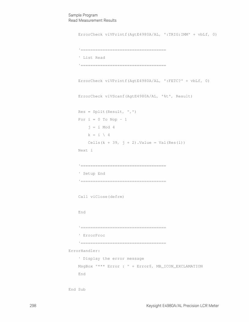
298 Keysight E4980A/AL Precision LCR Meter
Sample ProgramRead Measurement Results
9-
ErrorCheck viVPrintf(AgtE4980A/AL, ":TRIG:IMM" + vbLf, 0)
'===================================
' List Read
'===================================
ErrorCheck viVPrintf(AgtE4980A/AL, ":FETC?" + vbLf, 0)
ErrorCheck viVScanf(AgtE4980A/AL, "%t", Result)
Res = Split(Result, ",")
For i = 0 To Nop - 1
j = i Mod 4
k = i \ 4
Cells(k + 39, j + 2).Value = Val(Res(i))
Next i
'===================================
' Setup End
'===================================
Call viClose(defrm)
End
'===================================
' ErrorProc
'===================================
ErrorHandler:
' Display the error message
MsgBox "*** Error : " + Error$, MB_ICON_EXCLAMATION
End
End Sub
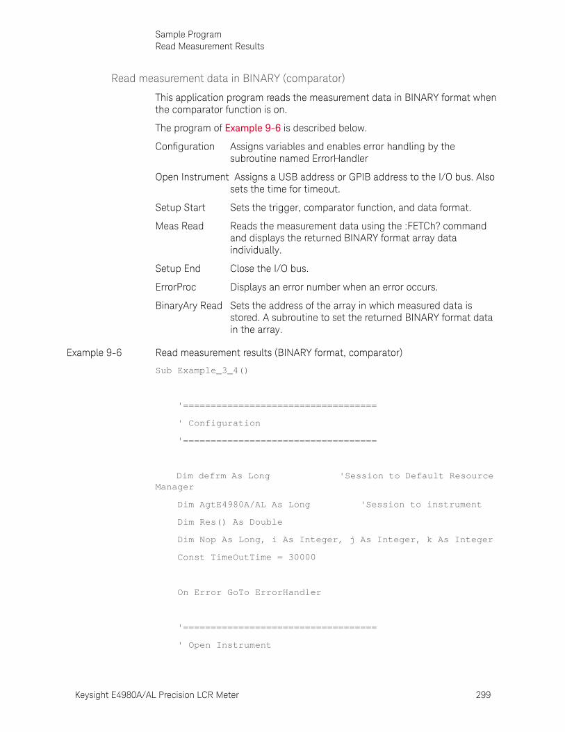
Keysight E4980A/AL Precision LCR Meter 299
Sample ProgramRead Measurement Results
Read measurement data in BINARY (comparator)
This application program reads the measurement data in BINARY format when the comparator function is on.
The program of Example 9-6 is described below.
Configuration Assigns variables and enables error handling by the subroutine named ErrorHandler
Open Instrument Assigns a USB address or GPIB address to the I/O bus. Also sets the time for timeout.
Setup Start Sets the trigger, comparator function, and data format.
Meas Read Reads the measurement data using the :FETCh? command and displays the returned BINARY format array data individually.
Setup End Close the I/O bus.
ErrorProc Displays an error number when an error occurs.
BinaryAry Read Sets the address of the array in which measured data is stored. A subroutine to set the returned BINARY format data in the array.
Example 9-6 Read measurement results (BINARY format, comparator)
Sub Example_3_4()
'===================================
' Configuration
'===================================
Dim defrm As Long 'Session to Default Resource Manager
Dim AgtE4980A/AL As Long 'Session to instrument
Dim Res() As Double
Dim Nop As Long, i As Integer, j As Integer, k As Integer
Const TimeOutTime = 30000
On Error GoTo ErrorHandler
'===================================
' Open Instrument
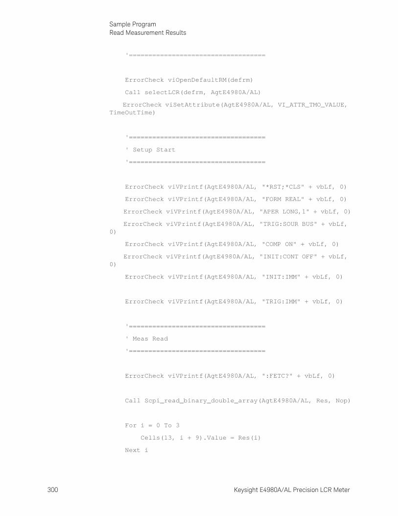
300 Keysight E4980A/AL Precision LCR Meter
Sample ProgramRead Measurement Results
9-
'===================================
ErrorCheck viOpenDefaultRM(defrm)
Call selectLCR(defrm, AgtE4980A/AL)
ErrorCheck viSetAttribute(AgtE4980A/AL, VI_ATTR_TMO_VALUE, TimeOutTime)
'===================================
' Setup Start
'===================================
ErrorCheck viVPrintf(AgtE4980A/AL, "*RST;*CLS" + vbLf, 0)
ErrorCheck viVPrintf(AgtE4980A/AL, "FORM REAL" + vbLf, 0)
ErrorCheck viVPrintf(AgtE4980A/AL, "APER LONG,1" + vbLf, 0)
ErrorCheck viVPrintf(AgtE4980A/AL, "TRIG:SOUR BUS" + vbLf, 0)
ErrorCheck viVPrintf(AgtE4980A/AL, "COMP ON" + vbLf, 0)
ErrorCheck viVPrintf(AgtE4980A/AL, "INIT:CONT OFF" + vbLf, 0)
ErrorCheck viVPrintf(AgtE4980A/AL, "INIT:IMM" + vbLf, 0)
ErrorCheck viVPrintf(AgtE4980A/AL, "TRIG:IMM" + vbLf, 0)
'===================================
' Meas Read
'===================================
ErrorCheck viVPrintf(AgtE4980A/AL, ":FETC?" + vbLf, 0)
Call Scpi_read_binary_double_array(AgtE4980A/AL, Res, Nop)
For i = 0 To 3
Cells(13, i + 9).Value = Res(i)
Next i
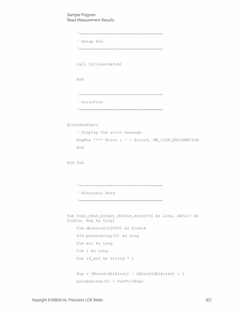
Keysight E4980A/AL Precision LCR Meter 301
Sample ProgramRead Measurement Results
'===================================
' Setup End
'===================================
Call viClose(defrm)
End
'===================================
' ErrorProc
'===================================
ErrorHandler:
' Display the error message
MsgBox "*** Error : " + Error$, MB_ICON_EXCLAMATION
End
End Sub
'===================================
' BinaryAry Read
'===================================
Sub Scpi_read_binary_double_array(vi As Long, data() As Double, Nop As Long)
Dim dblArray(10000) As Double
Dim paramsArray(3) As Long
Dim err As Long
Dim i As Long
Dim lf_eoi As String * 1
Nop = UBound(dblArray) - LBound(dblArray) + 1
paramsArray(0) = VarPtr(Nop)
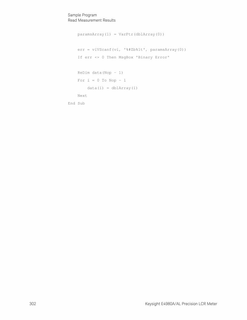
302 Keysight E4980A/AL Precision LCR Meter
Sample ProgramRead Measurement Results
9-
paramsArray(1) = VarPtr(dblArray(0))
err = viVScanf(vi, "%#Zb%1t", paramsArray(0))
If err <> 0 Then MsgBox "Binary Error"
ReDim data(Nop - 1)
For i = 0 To Nop - 1
data(i) = dblArray(i)
Next
End Sub
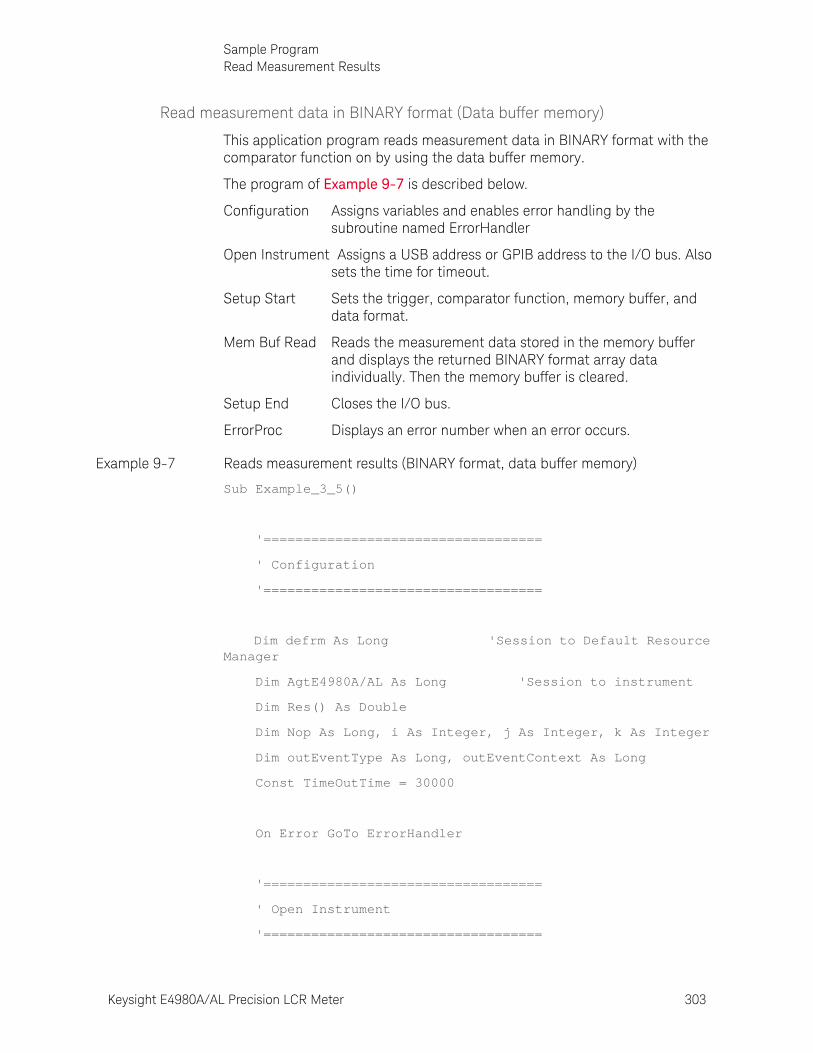
Keysight E4980A/AL Precision LCR Meter 303
Sample ProgramRead Measurement Results
Read measurement data in BINARY format (Data buffer memory)
This application program reads measurement data in BINARY format with the comparator function on by using the data buffer memory.
The program of Example 9-7 is described below.
Configuration Assigns variables and enables error handling by the subroutine named ErrorHandler
Open Instrument Assigns a USB address or GPIB address to the I/O bus. Also sets the time for timeout.
Setup Start Sets the trigger, comparator function, memory buffer, and data format.
Mem Buf Read Reads the measurement data stored in the memory buffer and displays the returned BINARY format array data individually. Then the memory buffer is cleared.
Setup End Closes the I/O bus.
ErrorProc Displays an error number when an error occurs.
Example 9-7 Reads measurement results (BINARY format, data buffer memory)
Sub Example_3_5()
'===================================
' Configuration
'===================================
Dim defrm As Long 'Session to Default Resource Manager
Dim AgtE4980A/AL As Long 'Session to instrument
Dim Res() As Double
Dim Nop As Long, i As Integer, j As Integer, k As Integer
Dim outEventType As Long, outEventContext As Long
Const TimeOutTime = 30000
On Error GoTo ErrorHandler
'===================================
' Open Instrument
'===================================
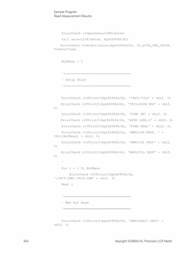
304 Keysight E4980A/AL Precision LCR Meter
Sample ProgramRead Measurement Results
9-
ErrorCheck viOpenDefaultRM(defrm)
Call selectLCR(defrm, AgtE4980A/AL)
ErrorCheck viSetAttribute(AgtE4980A/AL, VI_ATTR_TMO_VALUE, TimeOutTime)
NofMeas = 5
'===================================
' Setup Start
'===================================
ErrorCheck viVPrintf(AgtE4980A/AL, "*RST;*CLS" + vbLf, 0)
ErrorCheck viVPrintf(AgtE4980A/AL, "TRIG:SOUR BUS" + vbLf, 0)
ErrorCheck viVPrintf(AgtE4980A/AL, "COMP ON" + vbLf, 0)
ErrorCheck viVPrintf(AgtE4980A/AL, "APER LONG,5" + vbLf, 0)
ErrorCheck viVPrintf(AgtE4980A/AL, "FORM REAL" + vbLf, 0)
ErrorCheck viVPrintf(AgtE4980A/AL, "MEM:DIM DBUF, " + CStr(NofMeas) + vbLf, 0)
ErrorCheck viVPrintf(AgtE4980A/AL, "MEM:CLE DBUF" + vbLf, 0)
ErrorCheck viVPrintf(AgtE4980A/AL, "MEM:FILL DBUF" + vbLf, 0)
'
For i = 1 To NofMeas
ErrorCheck viVPrintf(AgtE4980A/AL, ":INIT:IMM;:TRIG:IMM" + vbLf, 0)
Next i
'===================================
' Mem Buf Read
'===================================
ErrorCheck viVPrintf(AgtE4980A/AL, "MEM:READ? DBUF" + vbLf, 0)
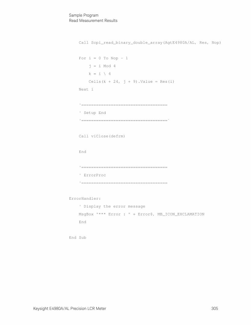
Keysight E4980A/AL Precision LCR Meter 305
Sample ProgramRead Measurement Results
Call Scpi_read_binary_double_array(AgtE4980A/AL, Res, Nop)
For i = 0 To Nop - 1
j = i Mod 4
k = i \ 4
Cells(k + 24, j + 9).Value = Res(i)
Next i
'===================================
' Setup End
'===================================`
Call viClose(defrm)
End
'===================================
' ErrorProc
'===================================
ErrorHandler:
' Display the error message
MsgBox "*** Error : " + Error$, MB_ICON_EXCLAMATION
End
End Sub
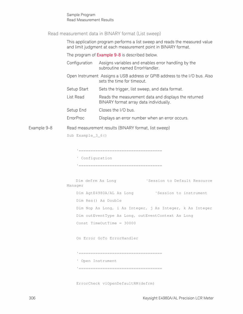
306 Keysight E4980A/AL Precision LCR Meter
Sample ProgramRead Measurement Results
9-
Read measurement data in BINARY format (List sweep)
This application program performs a list sweep and reads the measured value and limit judgment at each measurement point in BINARY format.
The program of Example 9-8 is described below.
Configuration Assigns variables and enables error handling by the subroutine named ErrorHandler.
Open Instrument Assigns a USB address or GPIB address to the I/O bus. Also sets the time for timeout.
Setup Start Sets the trigger, list sweep, and data format.
List Read Reads the measurement data and displays the returned BINARY format array data individually.
Setup End Closes the I/O bus.
ErrorProc Displays an error number when an error occurs.
Example 9-8 Read measurement results (BINARY format, list sweep)
Sub Example_3_6()
'===================================
' Configuration
'===================================
Dim defrm As Long 'Session to Default Resource Manager
Dim AgtE4980A/AL As Long 'Session to instrument
Dim Res() As Double
Dim Nop As Long, i As Integer, j As Integer, k As Integer
Dim outEventType As Long, outEventContext As Long
Const TimeOutTime = 30000
On Error GoTo ErrorHandler
'===================================
' Open Instrument
'===================================
ErrorCheck viOpenDefaultRM(defrm)
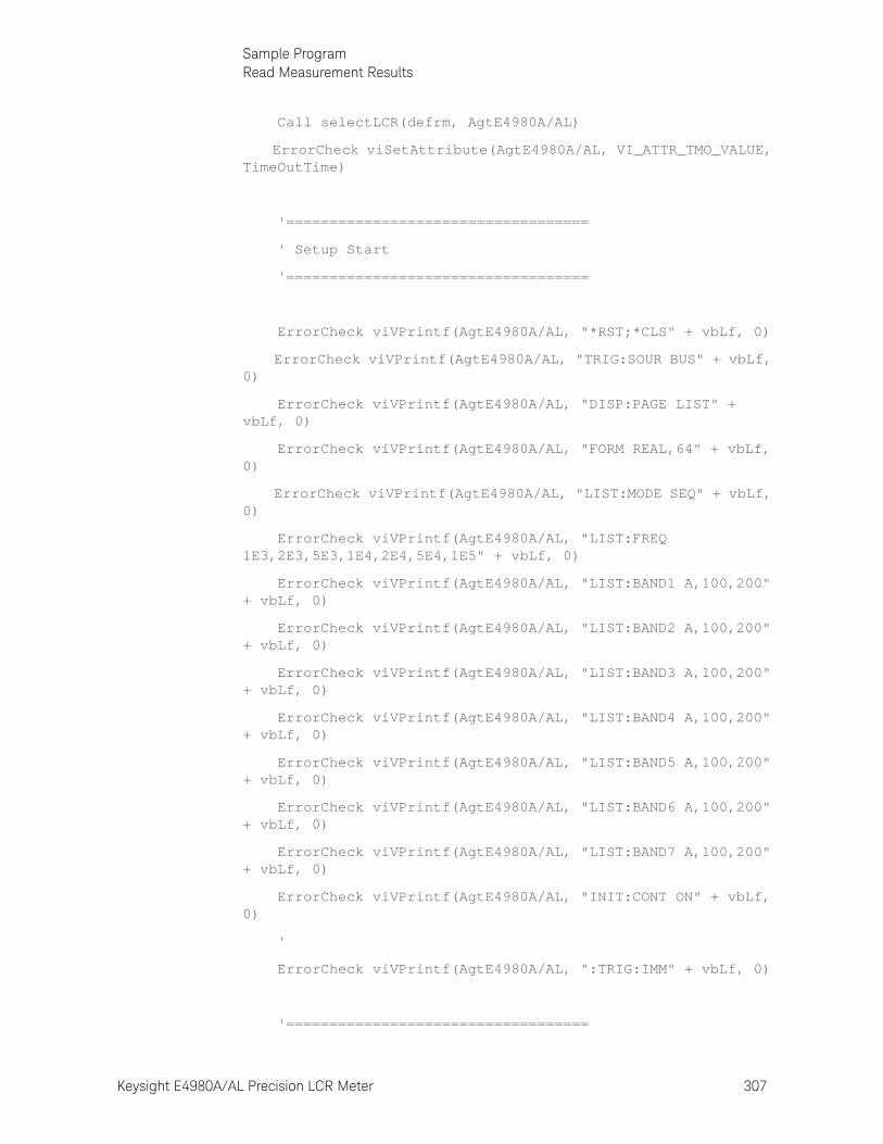
Keysight E4980A/AL Precision LCR Meter 307
Sample ProgramRead Measurement Results
Call selectLCR(defrm, AgtE4980A/AL)
ErrorCheck viSetAttribute(AgtE4980A/AL, VI_ATTR_TMO_VALUE, TimeOutTime)
'===================================
' Setup Start
'===================================
ErrorCheck viVPrintf(AgtE4980A/AL, "*RST;*CLS" + vbLf, 0)
ErrorCheck viVPrintf(AgtE4980A/AL, "TRIG:SOUR BUS" + vbLf, 0)
ErrorCheck viVPrintf(AgtE4980A/AL, "DISP:PAGE LIST" + vbLf, 0)
ErrorCheck viVPrintf(AgtE4980A/AL, "FORM REAL,64" + vbLf, 0)
ErrorCheck viVPrintf(AgtE4980A/AL, "LIST:MODE SEQ" + vbLf, 0)
ErrorCheck viVPrintf(AgtE4980A/AL, "LIST:FREQ 1E3,2E3,5E3,1E4,2E4,5E4,1E5" + vbLf, 0)
ErrorCheck viVPrintf(AgtE4980A/AL, "LIST:BAND1 A,100,200" + vbLf, 0)
ErrorCheck viVPrintf(AgtE4980A/AL, "LIST:BAND2 A,100,200" + vbLf, 0)
ErrorCheck viVPrintf(AgtE4980A/AL, "LIST:BAND3 A,100,200" + vbLf, 0)
ErrorCheck viVPrintf(AgtE4980A/AL, "LIST:BAND4 A,100,200" + vbLf, 0)
ErrorCheck viVPrintf(AgtE4980A/AL, "LIST:BAND5 A,100,200" + vbLf, 0)
ErrorCheck viVPrintf(AgtE4980A/AL, "LIST:BAND6 A,100,200" + vbLf, 0)
ErrorCheck viVPrintf(AgtE4980A/AL, "LIST:BAND7 A,100,200" + vbLf, 0)
ErrorCheck viVPrintf(AgtE4980A/AL, "INIT:CONT ON" + vbLf, 0)
'
ErrorCheck viVPrintf(AgtE4980A/AL, ":TRIG:IMM" + vbLf, 0)
'===================================
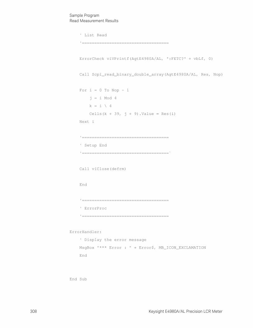
308 Keysight E4980A/AL Precision LCR Meter
Sample ProgramRead Measurement Results
9-
' List Read
'===================================
ErrorCheck viVPrintf(AgtE4980A/AL, ":FETC?" + vbLf, 0)
Call Scpi_read_binary_double_array(AgtE4980A/AL, Res, Nop)
For i = 0 To Nop - 1
j = i Mod 4
k = i \ 4
Cells(k + 39, j + 9).Value = Res(i)
Next i
'===================================
' Setup End
'===================================`
Call viClose(defrm)
End
'===================================
' ErrorProc
'===================================
ErrorHandler:
' Display the error message
MsgBox "*** Error : " + Error$, MB_ICON_EXCLAMATION
End
End Sub
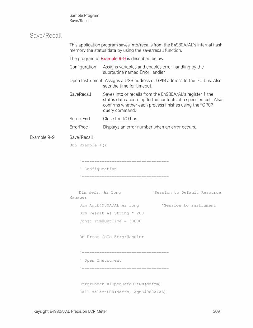
Keysight E4980A/AL Precision LCR Meter 309
Sample ProgramSave/Recall
Save/RecallThis application program saves into/recalls from the E4980A/AL’s internal flash memory the status data by using the save/recall function.
The program of Example 9-9 is described below.
Configuration Assigns variables and enables error handling by the subroutine named ErrorHandler
Open Instrument Assigns a USB address or GPIB address to the I/O bus. Also sets the time for timeout.
SaveRecall Saves into or recalls from the E4980A/AL’s register 1 the status data according to the contents of a specified cell. Also confirms whether each process finishes using the *OPC? query command.
Setup End Close the I/O bus.
ErrorProc Displays an error number when an error occurs.
Example 9-9 Save/Recall
Sub Example_4()
'===================================
' Configuration
'===================================
Dim defrm As Long 'Session to Default Resource Manager
Dim AgtE4980A/AL As Long 'Session to instrument
Dim Result As String * 200
Const TimeOutTime = 30000
On Error GoTo ErrorHandler
'===================================
' Open Instrument
'===================================
ErrorCheck viOpenDefaultRM(defrm)
Call selectLCR(defrm, AgtE4980A/AL)
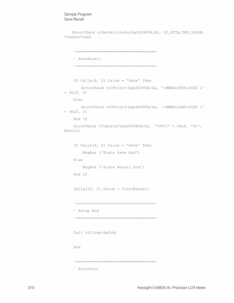
310 Keysight E4980A/AL Precision LCR Meter
Sample ProgramSave/Recall
9-
ErrorCheck viSetAttribute(AgtE4980A/AL, VI_ATTR_TMO_VALUE, TimeOutTime)
'===================================
' SaveRecall
'===================================
If Cells(9, 2).Value = "Save" Then
ErrorCheck viVPrintf(AgtE4980A/AL, ":MMEM:STOR:STAT 1" + vbLf, 0)
Else
ErrorCheck viVPrintf(AgtE4980A/AL, ":MMEM:LOAD:STAT 1" + vbLf, 0)
End If
ErrorCheck viVQueryf(AgtE4980A/AL, "*OPC?" + vbLf, "%t", Result)
If Cells(9, 2).Value = "Save" Then
MsgBox ("State Save End")
Else
MsgBox ("State Recall End")
End If
Cells(15, 2).Value = Trim(Result)
'===================================
' Setup End
'===================================
Call viClose(defrm)
End
'===================================
' ErrorProc

Keysight E4980A/AL Precision LCR Meter 311
Sample ProgramSave/Recall
'===================================
ErrorHandler:
' Display the error message
MsgBox "*** Error : " + Error$, MB_ICON_EXCLAMATION
End
End Sub
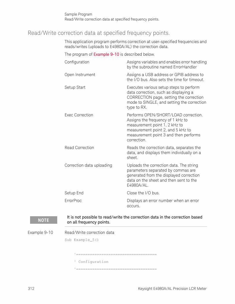
312 Keysight E4980A/AL Precision LCR Meter
Sample ProgramRead/Write correction data at specified frequency points.
9-
Read/Write correction data at specified frequency points.This application program performs correction at user-specified frequencies and reads/writes (uploads to E4980A/AL) the correction data.
The program of Example 9-10 is described below.
Configuration Assigns variables and enables error handling by the subroutine named ErrorHandler
Open Instrument Assigns a USB address or GPIB address to the I/O bus. Also sets the time for timeout.
Setup Start Executes various setup steps to perform data correction, such as displaying a CORRECTION page, setting the correction mode to SINGLE, and setting the correction type to RX.
Exec Correction Performs OPEN/SHORT/LOAD correction. Assigns the frequency of 1 kHz to measurement point 1, 2 kHz to measurement point 2, and 5 kHz to measurement point 3 and then performs correction.
Read Correction Reads the correction data, separates the data, and displays them individually on a sheet.
Correction data uploading Uploads the correction data. The string parameters separated by commas are generated from the displayed correction data on the sheet and then sent to the E4980A/AL.
Setup End Close the I/O bus.
ErrorProc Displays an error number when an error occurs.
Example 9-10 Read/Write correction data
Sub Example_5()
'===================================
' Configuration
'===================================
It is not possible to read/write the correction data in the correction based on all frequency points.

Keysight E4980A/AL Precision LCR Meter 313
Sample ProgramRead/Write correction data at specified frequency points.
Dim defrm As Long 'Session to Default Resource Manager
Dim AgtE4980A/AL As Long 'Session to instrument
Dim Res1 As Variant
Dim Result As String * 50000
Dim SendCorr As String
Dim i As Integer, FreqPoint As Integer, Std As Integer, Para As Integer, j As Integer, k As Integer
Dim Spot_Lop As Integer, Spot_Freq(10) As String
Dim CalData(200, 2, 1) As Variant
Const StdOpen As Integer = 0, StdShort As Integer = 1, StdLoad As Integer = 2
Const PriPara As Integer = 0, SecondPara As Integer = 1
Dim err As Long
Const TimeOutTime = 30000
On Error GoTo ErrorHandler
'===================================
' Open Instrument
'===================================
ErrorCheck viOpenDefaultRM(defrm)
Call selectLCR(defrm, AgtE4980A/AL)
ErrorCheck viSetAttribute(AgtE4980A/AL, VI_ATTR_TMO_VALUE, TimeOutTime)
'===================================
' Setup Start
'===================================
ErrorCheck viVPrintf(AgtE4980A/AL, "*RST;*CLS" + vbLf, 0)
ErrorCheck viVPrintf(AgtE4980A/AL, "DISP:PAGE CSET" + vbLf, 0)
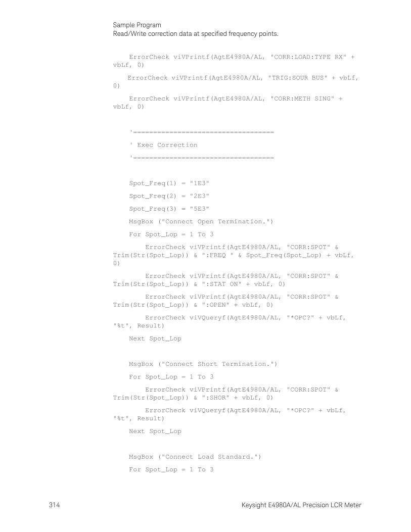
314 Keysight E4980A/AL Precision LCR Meter
Sample ProgramRead/Write correction data at specified frequency points.
9-
ErrorCheck viVPrintf(AgtE4980A/AL, "CORR:LOAD:TYPE RX" + vbLf, 0)
ErrorCheck viVPrintf(AgtE4980A/AL, "TRIG:SOUR BUS" + vbLf, 0)
ErrorCheck viVPrintf(AgtE4980A/AL, "CORR:METH SING" + vbLf, 0)
'===================================
' Exec Correction
'===================================
Spot_Freq(1) = "1E3"
Spot_Freq(2) = "2E3"
Spot_Freq(3) = "5E3"
MsgBox ("Connect Open Termination.")
For Spot_Lop = 1 To 3
ErrorCheck viVPrintf(AgtE4980A/AL, "CORR:SPOT" & Trim(Str(Spot_Lop)) & ":FREQ " & Spot_Freq(Spot_Lop) + vbLf, 0)
ErrorCheck viVPrintf(AgtE4980A/AL, "CORR:SPOT" & Trim(Str(Spot_Lop)) & ":STAT ON" + vbLf, 0)
ErrorCheck viVPrintf(AgtE4980A/AL, "CORR:SPOT" & Trim(Str(Spot_Lop)) & ":OPEN" + vbLf, 0)
ErrorCheck viVQueryf(AgtE4980A/AL, "*OPC?" + vbLf, "%t", Result)
Next Spot_Lop
MsgBox ("Connect Short Termination.")
For Spot_Lop = 1 To 3
ErrorCheck viVPrintf(AgtE4980A/AL, "CORR:SPOT" & Trim(Str(Spot_Lop)) & ":SHOR" + vbLf, 0)
ErrorCheck viVQueryf(AgtE4980A/AL, "*OPC?" + vbLf, "%t", Result)
Next Spot_Lop
MsgBox ("Connect Load Standard.")
For Spot_Lop = 1 To 3
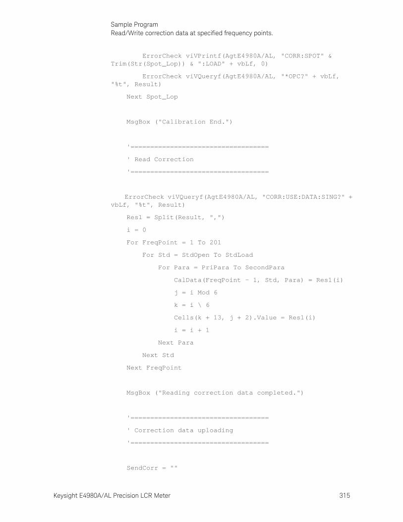
Keysight E4980A/AL Precision LCR Meter 315
Sample ProgramRead/Write correction data at specified frequency points.
ErrorCheck viVPrintf(AgtE4980A/AL, "CORR:SPOT" & Trim(Str(Spot_Lop)) & ":LOAD" + vbLf, 0)
ErrorCheck viVQueryf(AgtE4980A/AL, "*OPC?" + vbLf, "%t", Result)
Next Spot_Lop
MsgBox ("Calibration End.")
'===================================
' Read Correction
'===================================
ErrorCheck viVQueryf(AgtE4980A/AL, "CORR:USE:DATA:SING?" + vbLf, "%t", Result)
Res1 = Split(Result, ",")
i = 0
For FreqPoint = 1 To 201
For Std = StdOpen To StdLoad
For Para = PriPara To SecondPara
CalData(FreqPoint - 1, Std, Para) = Res1(i)
j = i Mod 6
k = i \ 6
Cells(k + 13, j + 2).Value = Res1(i)
i = i + 1
Next Para
Next Std
Next FreqPoint
MsgBox ("Reading correction data completed.")
'===================================
' Correction data uploading
'===================================
SendCorr = ""
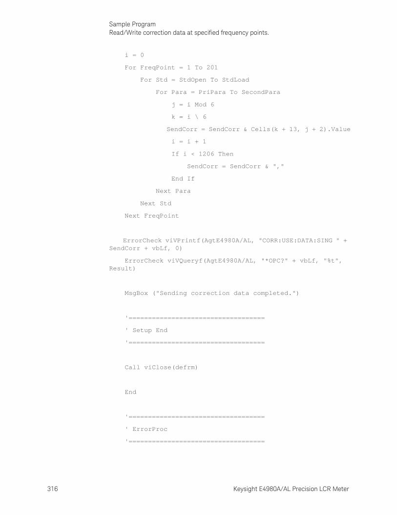
316 Keysight E4980A/AL Precision LCR Meter
Sample ProgramRead/Write correction data at specified frequency points.
9-
i = 0
For FreqPoint = 1 To 201
For Std = StdOpen To StdLoad
For Para = PriPara To SecondPara
j = i Mod 6
k = i \ 6
SendCorr = SendCorr & Cells(k + 13, j + 2).Value
i = i + 1
If i < 1206 Then
SendCorr = SendCorr & ","
End If
Next Para
Next Std
Next FreqPoint
ErrorCheck viVPrintf(AgtE4980A/AL, "CORR:USE:DATA:SING " + SendCorr + vbLf, 0)
ErrorCheck viVQueryf(AgtE4980A/AL, "*OPC?" + vbLf, "%t", Result)
MsgBox ("Sending correction data completed.")
'===================================
' Setup End
'===================================
Call viClose(defrm)
End
'===================================
' ErrorProc
'===================================

Keysight E4980A/AL Precision LCR Meter 317
Sample ProgramRead/Write correction data at specified frequency points.
ErrorHandler:
' Display the error message
MsgBox "*** Error : " + Error$, MB_ICON_EXCLAMATION
End
End Sub

318 Keysight E4980A/AL Precision LCR Meter
Sample ProgramRead/Write correction data at specified frequency points.
9-

319
Keysight E4980A/AL Precision LCR Meter
User’s Guide
10 SCPI Command Reference
This chapter describes the SCPI command reference for the Keysight E4980A/AL. It describes the commands using their abbreviated format in alphabetical order. If you want to look up commands using their fully qualified format, refer to the index for the desired SCPI command. If you want to look up commands by their function, refer to SCPI command list by function.
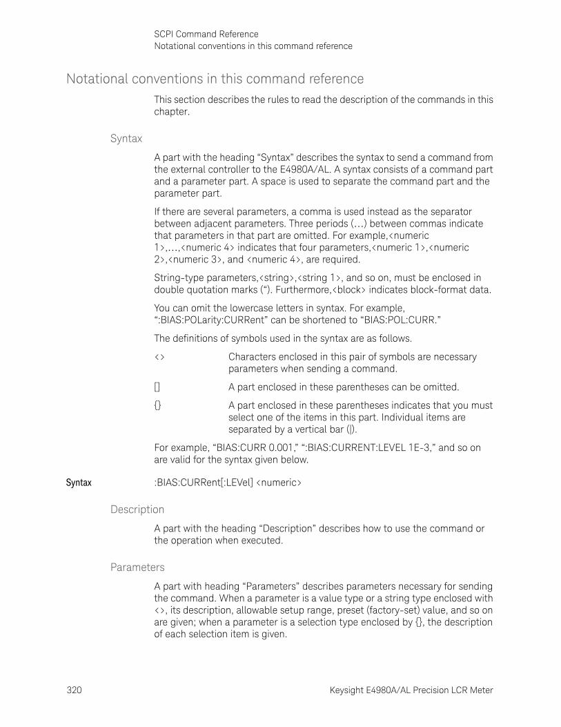
320 Keysight E4980A/AL Precision LCR Meter
SCPI Command ReferenceNotational conventions in this command reference
10-
Notational conventions in this command reference This section describes the rules to read the description of the commands in this chapter.
Syntax
A part with the heading “Syntax” describes the syntax to send a command from the external controller to the E4980A/AL. A syntax consists of a command part and a parameter part. A space is used to separate the command part and the parameter part.
If there are several parameters, a comma is used instead as the separator between adjacent parameters. Three periods (…) between commas indicate that parameters in that part are omitted. For example,<numeric 1>,…,<numeric 4> indicates that four parameters,<numeric 1>,<numeric 2>,<numeric 3>, and <numeric 4>, are required.
String-type parameters,<string>,<string 1>, and so on, must be enclosed in double quotation marks (“). Furthermore,<block> indicates block-format data.
You can omit the lowercase letters in syntax. For example, “:BIAS:POLarity:CURRent” can be shortened to “BIAS:POL:CURR.”
The definitions of symbols used in the syntax are as follows.
<> Characters enclosed in this pair of symbols are necessary parameters when sending a command.
[] A part enclosed in these parentheses can be omitted.
{} A part enclosed in these parentheses indicates that you must select one of the items in this part. Individual items are separated by a vertical bar (|).
For example, “BIAS:CURR 0.001,” “:BIAS:CURRENT:LEVEL 1E-3,” and so on are valid for the syntax given below.
Syntax :BIAS:CURRent[:LEVel] <numeric>
Description
A part with the heading “Description” describes how to use the command or the operation when executed.
Parameters
A part with heading “Parameters” describes parameters necessary for sending the command. When a parameter is a value type or a string type enclosed with <>, its description, allowable setup range, preset (factory-set) value, and so on are given; when a parameter is a selection type enclosed by {}, the description of each selection item is given.
Keysight E4980A/AL Precision LCR Meter 321
SCPI Command ReferenceNotational conventions in this command reference
Equivalent key
A part with the heading “Equivalent key” shows the operational procedure for the front panel keys. An equivalent key has the same effect as a certain command.
[Key] Indicates that you press the key named Key.
[Key] - Item Indicates a series of key operations in which you press [Key], select the item called Item (softkey or field name) on the displayed menu using the cursor keys, and then press the softkey.
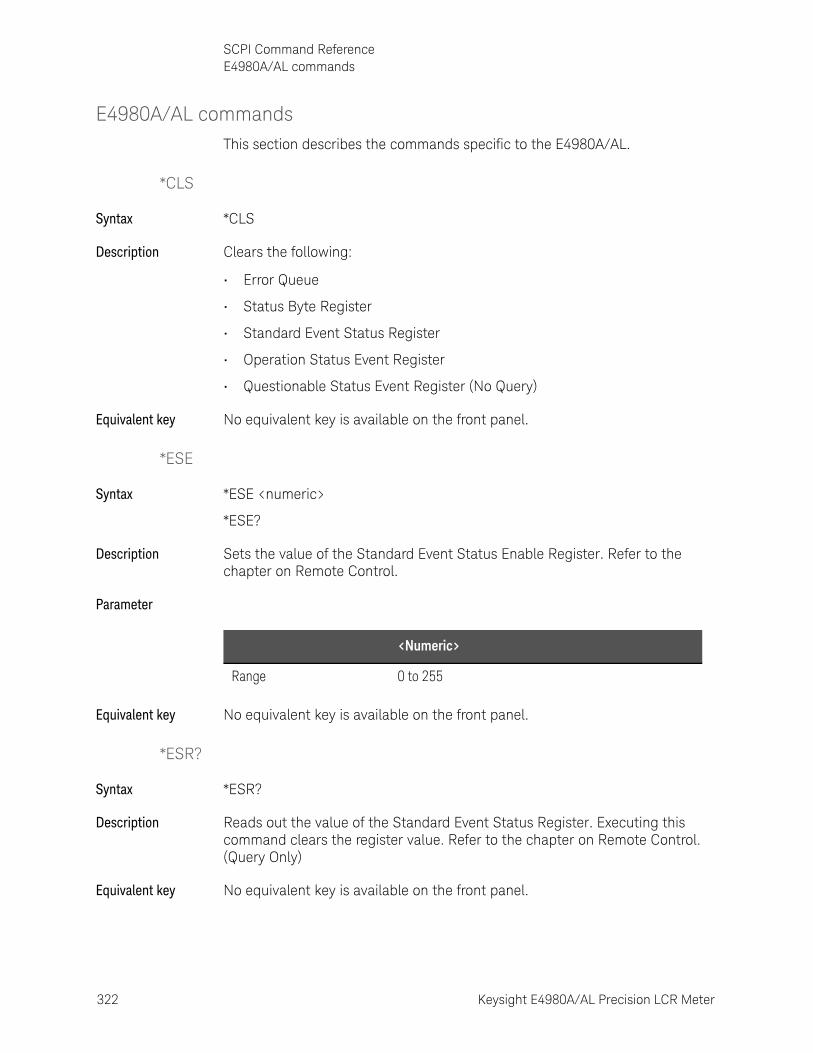
322 Keysight E4980A/AL Precision LCR Meter
SCPI Command ReferenceE4980A/AL commands
10-
E4980A/AL commandsThis section describes the commands specific to the E4980A/AL.
*CLS
Syntax *CLS
Description Clears the following:
• Error Queue
• Status Byte Register
• Standard Event Status Register
• Operation Status Event Register
• Questionable Status Event Register (No Query)
Equivalent key No equivalent key is available on the front panel.
*ESE
Syntax *ESE <numeric>
*ESE?
Description Sets the value of the Standard Event Status Enable Register. Refer to the chapter on Remote Control.
Parameter
Equivalent key No equivalent key is available on the front panel.
*ESR?
Syntax *ESR?
Description Reads out the value of the Standard Event Status Register. Executing this command clears the register value. Refer to the chapter on Remote Control. (Query Only)
Equivalent key No equivalent key is available on the front panel.
<Numeric>
Range 0 to 255
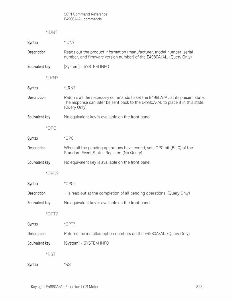
Keysight E4980A/AL Precision LCR Meter 323
SCPI Command ReferenceE4980A/AL commands
*IDN?
Syntax *IDN?
Description Reads out the product information (manufacturer, model number, serial number, and firmware version number) of the E4980A/AL. (Query Only)
Equivalent key [System] - SYSTEM INFO
*LRN?
Syntax *LRN?
Description Returns all the necessary commands to set the E4980A/AL at its present state. The response can later be sent back to the E4980A/AL to place it in this state. (Query Only)
Equivalent key No equivalent key is available on the front panel.
*OPC
Syntax *OPC
Description When all the pending operations have ended, sets OPC bit (Bit 0) of the Standard Event Status Register. (No Query)
Equivalent key No equivalent key is available on the front panel.
*OPC?
Syntax *OPC?
Description 1 is read out at the completion of all pending operations. (Query Only)
Equivalent key No equivalent key is available on the front panel.
*OPT?
Syntax *OPT?
Description Returns the installed option numbers on the E4980A/AL. (Query Only)
Equivalent key [System] - SYSTEM INFO
*RST
Syntax *RST
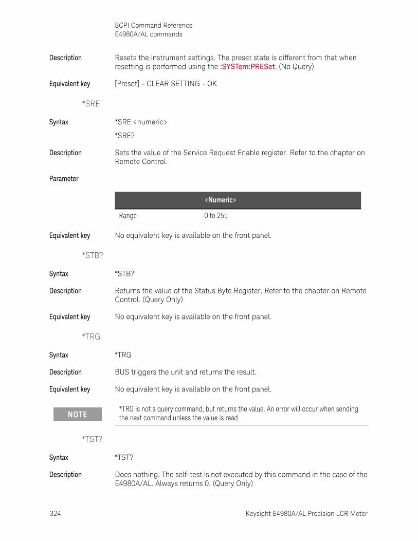
324 Keysight E4980A/AL Precision LCR Meter
SCPI Command ReferenceE4980A/AL commands
10-
Description Resets the instrument settings. The preset state is different from that when resetting is performed using the :SYSTem:PRESet. (No Query)
Equivalent key [Preset] - CLEAR SETTING - OK
*SRE
Syntax *SRE <numeric>
*SRE?
Description Sets the value of the Service Request Enable register. Refer to the chapter on Remote Control.
Parameter
Equivalent key No equivalent key is available on the front panel.
*STB?
Syntax *STB?
Description Returns the value of the Status Byte Register. Refer to the chapter on Remote Control. (Query Only)
Equivalent key No equivalent key is available on the front panel.
*TRG
Syntax *TRG
Description BUS triggers the unit and returns the result.
Equivalent key No equivalent key is available on the front panel.
*TST?
Syntax *TST?
Description Does nothing. The self-test is not executed by this command in the case of the E4980A/AL. Always returns 0. (Query Only)
<Numeric>
Range 0 to 255
*TRG is not a query command, but returns the value. An error will occur when sending the next command unless the value is read.

Keysight E4980A/AL Precision LCR Meter 325
SCPI Command ReferenceE4980A/AL commands
Equivalent key No equivalent key is available on the front panel.
*WAI
Syntax *WAI
Description Waits until all commands sent before this command have been executed. The following commands are then executed. (No Query)
Equivalent key No equivalent key is available on the front panel.
:ABORt
Syntax :ABORt
Description Resets the trigger system. The trigger state is then in the “Idle” state on the state diagram. (No Query)
Equivalent key [Meas Setup] - MEAS SETUP - REF A - MEAS ABORT
[Meas Setup] - MEAS SETUP - B - MEAS ABORT
[Meas Setup] - CORRECTION - OPEN - MEAS OPEN - ABORT
[Meas Setup] - CORRECTION - SHORT - MEAS SHORT - ABORT
:AMPLitude:ALC
Syntax :AMPLitude:ALC {ON|OFF|1|0}
:AMPLitude:ALC?
Description Enables the Automatic Level Control (ALC).
Parameter
Equivalent key [Meas Setup] - MEAS SETUP - ALC
:APERture
Syntax :APERture {SHORt|MEDium|LONG},<numeric>
:APERture?
Description Sets the measurement time mode and the averaging rate.
Description
ON or 1 Enables the Automatic Level Control
OFF or 0 (Preset value) Disables the Automatic Level Control
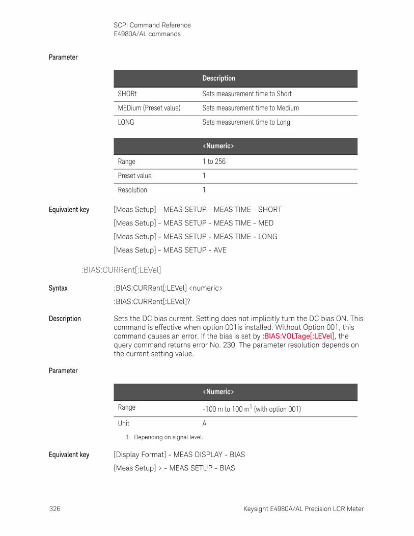
326 Keysight E4980A/AL Precision LCR Meter
SCPI Command ReferenceE4980A/AL commands
10-
Parameter
Equivalent key [Meas Setup] - MEAS SETUP - MEAS TIME - SHORT
[Meas Setup] - MEAS SETUP - MEAS TIME - MED
[Meas Setup] - MEAS SETUP - MEAS TIME - LONG
[Meas Setup] - MEAS SETUP - AVE
:BIAS:CURRent[:LEVel]
Syntax :BIAS:CURRent[:LEVel] <numeric>
:BIAS:CURRent[:LEVel]?
Description Sets the DC bias current. Setting does not implicitly turn the DC bias ON. This command is effective when option 001is installed. Without Option 001, this command causes an error. If the bias is set by :BIAS:VOLTage[:LEVel], the query command returns error No. 230. The parameter resolution depends on the current setting value.
Parameter
Equivalent key [Display Format] - MEAS DISPLAY - BIAS
[Meas Setup] > - MEAS SETUP - BIAS
Description
SHORt Sets measurement time to Short
MEDium (Preset value) Sets measurement time to Medium
LONG Sets measurement time to Long
<Numeric>
Range 1 to 256
Preset value 1
Resolution 1
<Numeric>
Range -100 m to 100 m1 (with option 001)
Unit A
1. Depending on signal level.
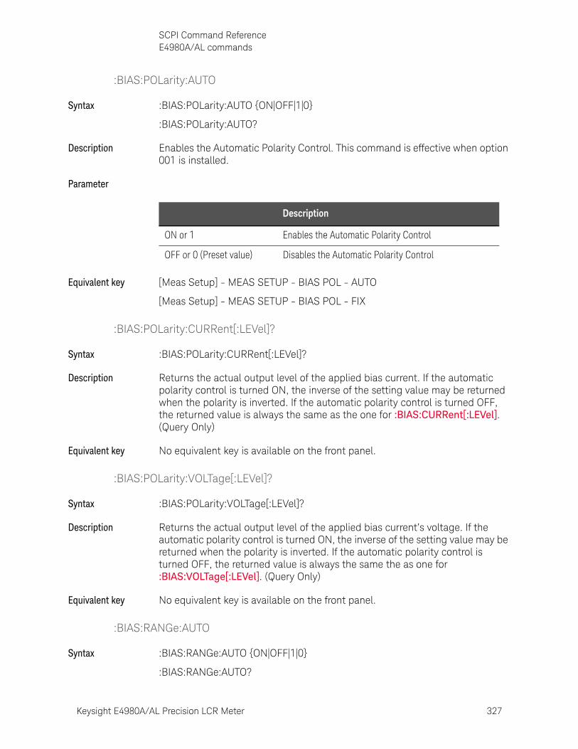
Keysight E4980A/AL Precision LCR Meter 327
SCPI Command ReferenceE4980A/AL commands
:BIAS:POLarity:AUTO
Syntax :BIAS:POLarity:AUTO {ON|OFF|1|0}
:BIAS:POLarity:AUTO?
Description Enables the Automatic Polarity Control. This command is effective when option 001 is installed.
Parameter
Equivalent key [Meas Setup] - MEAS SETUP - BIAS POL - AUTO
[Meas Setup] - MEAS SETUP - BIAS POL - FIX
:BIAS:POLarity:CURRent[:LEVel]?
Syntax :BIAS:POLarity:CURRent[:LEVel]?
Description Returns the actual output level of the applied bias current. If the automatic polarity control is turned ON, the inverse of the setting value may be returned when the polarity is inverted. If the automatic polarity control is turned OFF, the returned value is always the same as the one for :BIAS:CURRent[:LEVel]. (Query Only)
Equivalent key No equivalent key is available on the front panel.
:BIAS:POLarity:VOLTage[:LEVel]?
Syntax :BIAS:POLarity:VOLTage[:LEVel]?
Description Returns the actual output level of the applied bias current’s voltage. If the automatic polarity control is turned ON, the inverse of the setting value may be returned when the polarity is inverted. If the automatic polarity control is turned OFF, the returned value is always the same the as one for :BIAS:VOLTage[:LEVel]. (Query Only)
Equivalent key No equivalent key is available on the front panel.
:BIAS:RANGe:AUTO
Syntax :BIAS:RANGe:AUTO {ON|OFF|1|0}
:BIAS:RANGe:AUTO?
Description
ON or 1 Enables the Automatic Polarity Control
OFF or 0 (Preset value) Disables the Automatic Polarity Control

328 Keysight E4980A/AL Precision LCR Meter
SCPI Command ReferenceE4980A/AL commands
10-
Description Sets the DC bias range to AUTO (ON) or FIX (OFF).
When the DC bias range is FIX, ”#” is displayed in the BIAS field of the display.
When the DC bias range is set to FIX, resolution of the test signal voltage is fixed, and accuracy is changed. For details, refer to “DC bias signal, Test signal voltage” in data sheet.
Parameter
Equivalent key No equivalent key is available on the front panel.
:BIAS:STATe
Syntax :BIAS:STATe {ON|OFF|1|0}
:BIAS:STATe?
Description Enables DC bias. DC bias is automatically turned off after recalling the state from memory. When DC bias is set to ON, DC bias that has been set with :BIAS:CURRent[:LEVel] or :BIAS:VOLTage[:LEVel] is output.
Parameter
Equivalent key [DC Bias]
:BIAS:VOLTage[:LEVel]
Syntax :BIAS:VOLTage[:LEVel] <numeric>
:BIAS:VOLTage[:LEVel]?
Description Sets the DC bias voltage. Setting does not implicitly turn the DC bias ON. If the bias is set by :BIAS:CURRent[:LEVel], the query command returns error No. 230. The parameter resolution depends on the setting voltage value.
Description
ON or 1 (Preset value) Sets the DC bias range to ON
OFF or 0 Sets the DC bias range to OFF
Description
ON or 1 Enables the DC bias
OFF or 0 (Preset value) Disables the DC bias
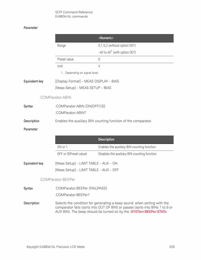
Keysight E4980A/AL Precision LCR Meter 329
SCPI Command ReferenceE4980A/AL commands
Parameter
Equivalent key [Display Format] - MEAS DISPLAY - BIAS
[Meas Setup] - MEAS SETUP - BIAS
:COMParator:ABIN
Syntax :COMParator:ABIN {ON|OFF|1|0}
:COMParator:ABIN?
Description Enables the auxiliary BIN counting function of the comparator.
Parameter
Equivalent key [Meas Setup] - LIMIT TABLE - AUX - ON
[Meas Setup] - LIMIT TABLE - AUX - OFF
:COMParator:BEEPer
Syntax :COMParator:BEEPer {FAIL|PASS}
:COMParator:BEEPer?
Description Selects the condition for generating a beep sound: when sorting with the comparator fails (sorts into OUT OF BIN) or passes (sorts into BINs 1 to 9 or AUX BIN). The beep should be turned on by the :SYSTem:BEEPer:STATe.
<Numeric>
Range 0,1.5,2 (without option 001)
-40 to 401 (with option 001)
Preset value 0
Unit V
1. Depending on signal level.
Description
ON or 1 Enables the auxiliary BIN counting function
OFF or 0(Preset value) Disables the auxiliary BIN counting function
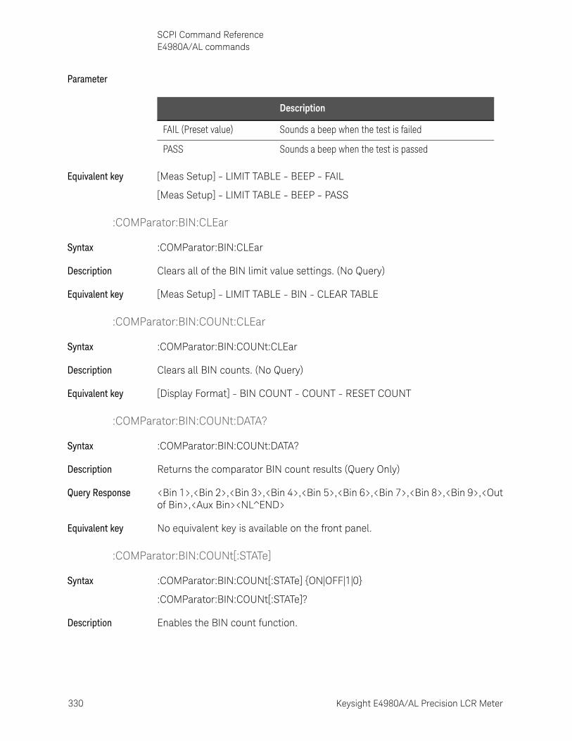
330 Keysight E4980A/AL Precision LCR Meter
SCPI Command ReferenceE4980A/AL commands
10-
Parameter
Equivalent key [Meas Setup] - LIMIT TABLE - BEEP - FAIL
[Meas Setup] - LIMIT TABLE - BEEP - PASS
:COMParator:BIN:CLEar
Syntax :COMParator:BIN:CLEar
Description Clears all of the BIN limit value settings. (No Query)
Equivalent key [Meas Setup] - LIMIT TABLE - BIN - CLEAR TABLE
:COMParator:BIN:COUNt:CLEar
Syntax :COMParator:BIN:COUNt:CLEar
Description Clears all BIN counts. (No Query)
Equivalent key [Display Format] - BIN COUNT - COUNT - RESET COUNT
:COMParator:BIN:COUNt:DATA?
Syntax :COMParator:BIN:COUNt:DATA?
Description Returns the comparator BIN count results (Query Only)
Query Response <Bin 1>,<Bin 2>,<Bin 3>,<Bin 4>,<Bin 5>,<Bin 6>,<Bin 7>,<Bin 8>,<Bin 9>,<Out of Bin>,<Aux Bin><NL^END>
Equivalent key No equivalent key is available on the front panel.
:COMParator:BIN:COUNt[:STATe]
Syntax :COMParator:BIN:COUNt[:STATe] {ON|OFF|1|0}
:COMParator:BIN:COUNt[:STATe]?
Description Enables the BIN count function.
Description
FAIL (Preset value) Sounds a beep when the test is failed
PASS Sounds a beep when the test is passed
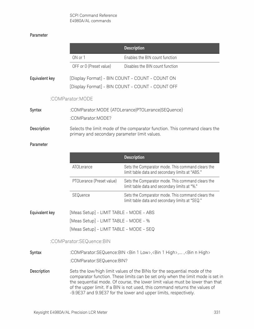
Keysight E4980A/AL Precision LCR Meter 331
SCPI Command ReferenceE4980A/AL commands
Parameter
Equivalent key [Display Format] - BIN COUNT - COUNT - COUNT ON
[Display Format] - BIN COUNT - COUNT - COUNT OFF
:COMParator:MODE
Syntax :COMParator:MODE {ATOLerance|PTOLerance|SEQuence}
:COMParator:MODE?
Description Selects the limit mode of the comparator function. This command clears the primary and secondary parameter limit values.
Parameter
Equivalent key [Meas Setup] - LIMIT TABLE - MODE - ABS
[Meas Setup] - LIMIT TABLE - MODE - %
[Meas Setup] - LIMIT TABLE - MODE - SEQ
:COMParator:SEQuence:BIN
Syntax :COMParator:SEQuence:BIN <Bin 1 Low>,<Bin 1 High>,... ,<Bin n High>
:COMParator:SEQuence:BIN?
Description Sets the low/high limit values of the BINs for the sequential mode of the comparator function. These limits can be set only when the limit mode is set in the sequential mode. Of course, the lower limit value must be lower than that of the upper limit. If a BIN is not used, this command returns the values of -9.9E37 and 9.9E37 for the lower and upper limits, respectively.
Description
ON or 1 Enables the BIN count function
OFF or 0 (Preset value) Disables the BIN count function
Description
ATOLerance Sets the Comparator mode. This command clears the limit table data and secondary limits at “ABS.”
PTOLerance (Preset value) Sets the Comparator mode. This command clears the limit table data and secondary limits at “%.”
SEQuence Sets the Comparator mode. This command clears the limit table data and secondary limits at “SEQ.”

332 Keysight E4980A/AL Precision LCR Meter
SCPI Command ReferenceE4980A/AL commands
10-
Parameter
Example of Use viVPrintf(AgtE4980A/AL, "COMP:MODE SEQ" + vbLf, 0)
viVPrintf(AgtE4980A/AL, "FUNC:IMP RX" + vbLf, 0)
viVPrintf(AgtE4980A/AL, "COMP:SEQ:BIN -9.9e37, 100,110,120,130,140, 9.9e37,150" + vbLf, 0)
Equivalent key [Meas Setup] - LIMIT TABLE - Bin 1 LOW
[Meas Setup] - LIMIT TABLE - Bin 1 - 9 HIGH
:COMParator:SLIMit
Syntax :COMParator:SLIMit <Low>,<High>
:COMParator:SLIMit?
Description Sets the lower/upper limit values for the comparator function’s secondary parameter.
Parameter
Equivalent key [Meas Setup] - LIMIT TABLE - 2nd LOW
[Meas Setup] - LIMIT TABLE - 2nd HIGH
:COMParator[:STATe]
Syntax :COMParator[:STATe] {ON|OFF|1|0}
:COMParator[:STATe]?
Description Enables the comparator function.
<Bin 1 Low>
Unit Depends on :FUNCtion:IMPedance[:TYPE]
<Bin n High>
Range of n 1 to 9
Unit Depends on :FUNCtion:IMPedance[:TYPE]
<Low>,<High>
Preset value -9.9E+37, 9.9E+37
Unit Depends on :FUNCtion:IMPedance[:TYPE]
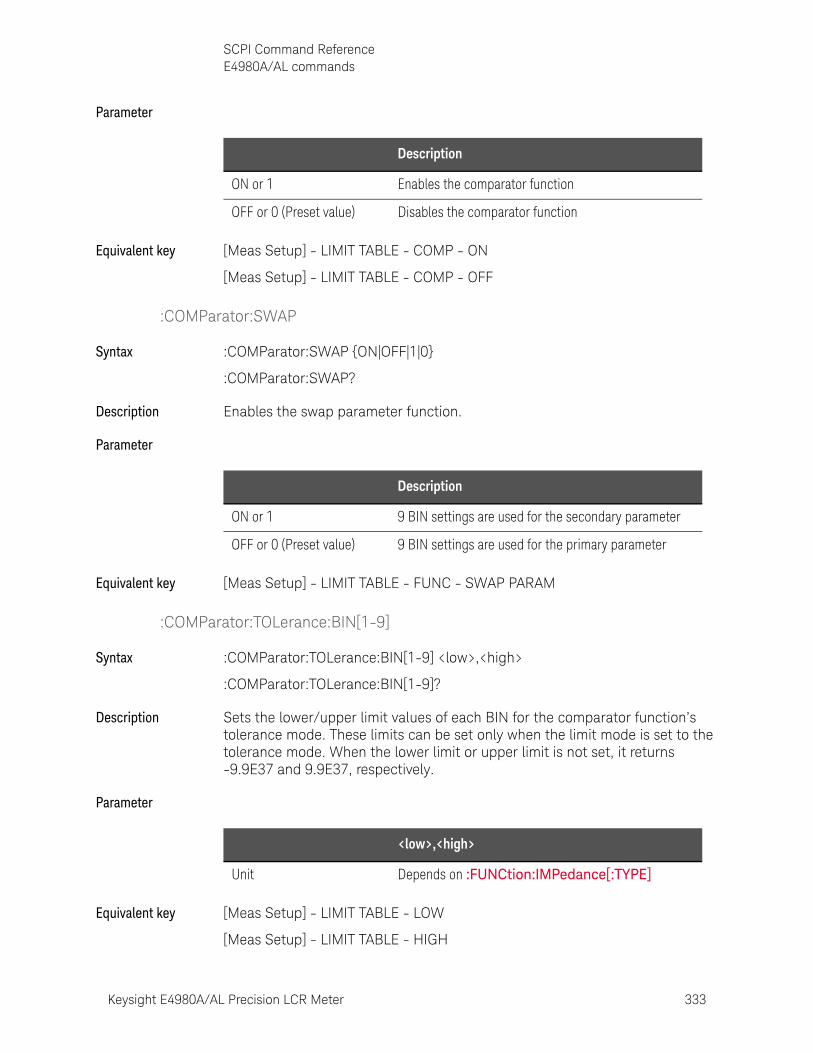
Keysight E4980A/AL Precision LCR Meter 333
SCPI Command ReferenceE4980A/AL commands
Parameter
Equivalent key [Meas Setup] - LIMIT TABLE - COMP - ON
[Meas Setup] - LIMIT TABLE - COMP - OFF
:COMParator:SWAP
Syntax :COMParator:SWAP {ON|OFF|1|0}
:COMParator:SWAP?
Description Enables the swap parameter function.
Parameter
Equivalent key [Meas Setup] - LIMIT TABLE - FUNC - SWAP PARAM
:COMParator:TOLerance:BIN[1-9]
Syntax :COMParator:TOLerance:BIN[1-9] <low>,<high>
:COMParator:TOLerance:BIN[1-9]?
Description Sets the lower/upper limit values of each BIN for the comparator function’s tolerance mode. These limits can be set only when the limit mode is set to the tolerance mode. When the lower limit or upper limit is not set, it returns -9.9E37 and 9.9E37, respectively.
Parameter
Equivalent key [Meas Setup] - LIMIT TABLE - LOW
[Meas Setup] - LIMIT TABLE - HIGH
Description
ON or 1 Enables the comparator function
OFF or 0 (Preset value) Disables the comparator function
Description
ON or 1 9 BIN settings are used for the secondary parameter
OFF or 0 (Preset value) 9 BIN settings are used for the primary parameter
<low>,<high>
Unit Depends on :FUNCtion:IMPedance[:TYPE]
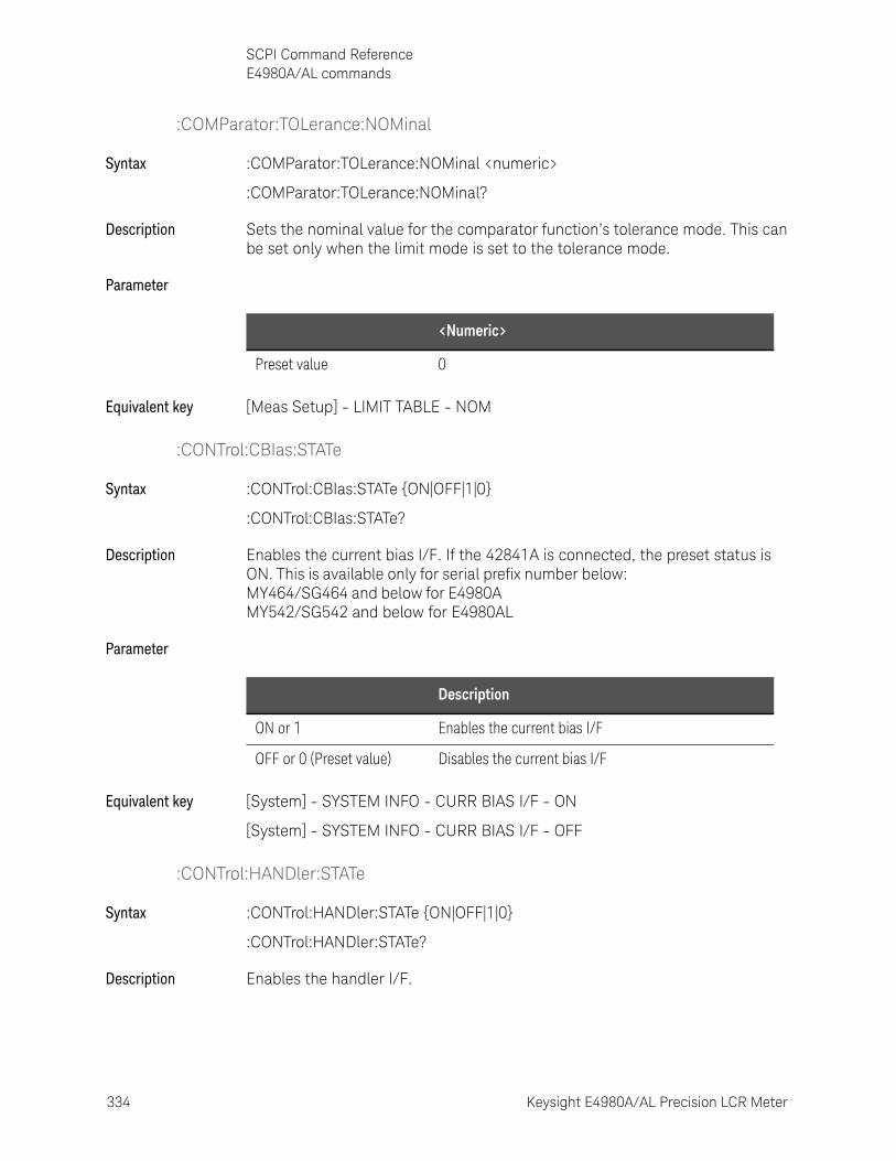
334 Keysight E4980A/AL Precision LCR Meter
SCPI Command ReferenceE4980A/AL commands
10-
:COMParator:TOLerance:NOMinal
Syntax :COMParator:TOLerance:NOMinal <numeric>
:COMParator:TOLerance:NOMinal?
Description Sets the nominal value for the comparator function’s tolerance mode. This can be set only when the limit mode is set to the tolerance mode.
Parameter
Equivalent key [Meas Setup] - LIMIT TABLE - NOM
:CONTrol:CBIas:STATe
Syntax :CONTrol:CBIas:STATe {ON|OFF|1|0}
:CONTrol:CBIas:STATe?
Description Enables the current bias I/F. If the 42841A is connected, the preset status is ON. This is available only for serial prefix number below: MY464/SG464 and below for E4980A MY542/SG542 and below for E4980AL
Parameter
Equivalent key [System] - SYSTEM INFO - CURR BIAS I/F - ON
[System] - SYSTEM INFO - CURR BIAS I/F - OFF
:CONTrol:HANDler:STATe
Syntax :CONTrol:HANDler:STATe {ON|OFF|1|0}
:CONTrol:HANDler:STATe?
Description Enables the handler I/F.
<Numeric>
Preset value 0
Description
ON or 1 Enables the current bias I/F
OFF or 0 (Preset value) Disables the current bias I/F
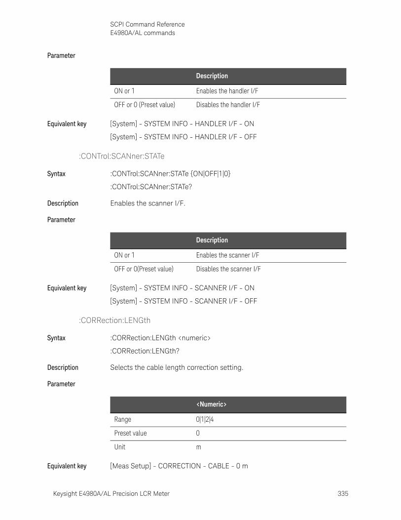
Keysight E4980A/AL Precision LCR Meter 335
SCPI Command ReferenceE4980A/AL commands
Parameter
Equivalent key [System] - SYSTEM INFO - HANDLER I/F - ON
[System] - SYSTEM INFO - HANDLER I/F - OFF
:CONTrol:SCANner:STATe
Syntax :CONTrol:SCANner:STATe {ON|OFF|1|0}
:CONTrol:SCANner:STATe?
Description Enables the scanner I/F.
Parameter
Equivalent key [System] - SYSTEM INFO - SCANNER I/F - ON
[System] - SYSTEM INFO - SCANNER I/F - OFF
:CORRection:LENGth
Syntax :CORRection:LENGth <numeric>
:CORRection:LENGth?
Description Selects the cable length correction setting.
Parameter
Equivalent key [Meas Setup] - CORRECTION - CABLE - 0 m
Description
ON or 1 Enables the handler I/F
OFF or 0 (Preset value) Disables the handler I/F
Description
ON or 1 Enables the scanner I/F
OFF or 0(Preset value) Disables the scanner I/F
<Numeric>
Range 0|1|2|4
Preset value 0
Unit m
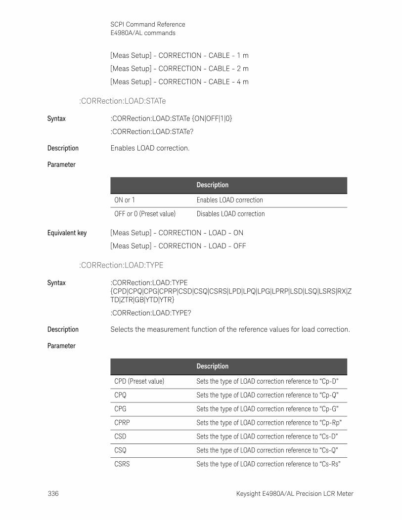
336 Keysight E4980A/AL Precision LCR Meter
SCPI Command ReferenceE4980A/AL commands
10-
[Meas Setup] - CORRECTION - CABLE - 1 m
[Meas Setup] - CORRECTION - CABLE - 2 m
[Meas Setup] - CORRECTION - CABLE - 4 m
:CORRection:LOAD:STATe
Syntax :CORRection:LOAD:STATe {ON|OFF|1|0}
:CORRection:LOAD:STATe?
Description Enables LOAD correction.
Parameter
Equivalent key [Meas Setup] - CORRECTION - LOAD - ON
[Meas Setup] - CORRECTION - LOAD - OFF
:CORRection:LOAD:TYPE
Syntax :CORRection:LOAD:TYPE {CPD|CPQ|CPG|CPRP|CSD|CSQ|CSRS|LPD|LPQ|LPG|LPRP|LSD|LSQ|LSRS|RX|ZTD|ZTR|GB|YTD|YTR}
:CORRection:LOAD:TYPE?
Description Selects the measurement function of the reference values for load correction.
Parameter
Description
ON or 1 Enables LOAD correction
OFF or 0 (Preset value) Disables LOAD correction
Description
CPD (Preset value) Sets the type of LOAD correction reference to “Cp-D”
CPQ Sets the type of LOAD correction reference to “Cp-Q”
CPG Sets the type of LOAD correction reference to “Cp-G”
CPRP Sets the type of LOAD correction reference to “Cp-Rp”
CSD Sets the type of LOAD correction reference to “Cs-D”
CSQ Sets the type of LOAD correction reference to “Cs-Q”
CSRS Sets the type of LOAD correction reference to “Cs-Rs”
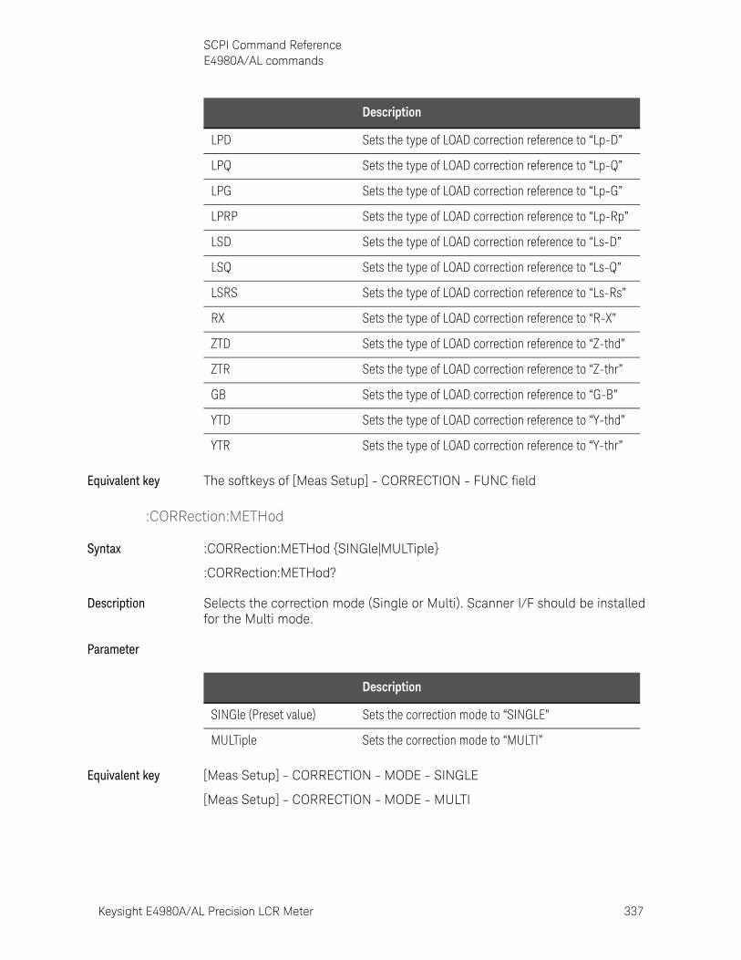
Keysight E4980A/AL Precision LCR Meter 337
SCPI Command ReferenceE4980A/AL commands
Equivalent key The softkeys of [Meas Setup] - CORRECTION - FUNC field
:CORRection:METHod
Syntax :CORRection:METHod {SINGle|MULTiple}
:CORRection:METHod?
Description Selects the correction mode (Single or Multi). Scanner I/F should be installed for the Multi mode.
Parameter
Equivalent key [Meas Setup] - CORRECTION - MODE - SINGLE
[Meas Setup] - CORRECTION - MODE - MULTI
LPD Sets the type of LOAD correction reference to “Lp-D”
LPQ Sets the type of LOAD correction reference to “Lp-Q”
LPG Sets the type of LOAD correction reference to “Lp-G”
LPRP Sets the type of LOAD correction reference to “Lp-Rp”
LSD Sets the type of LOAD correction reference to “Ls-D”
LSQ Sets the type of LOAD correction reference to “Ls-Q”
LSRS Sets the type of LOAD correction reference to “Ls-Rs”
RX Sets the type of LOAD correction reference to “R-X”
ZTD Sets the type of LOAD correction reference to “Z-thd”
ZTR Sets the type of LOAD correction reference to “Z-thr”
GB Sets the type of LOAD correction reference to “G-B”
YTD Sets the type of LOAD correction reference to “Y-thd”
YTR Sets the type of LOAD correction reference to “Y-thr”
Description
Description
SINGle (Preset value) Sets the correction mode to “SINGLE”
MULTiple Sets the correction mode to “MULTI”

338 Keysight E4980A/AL Precision LCR Meter
SCPI Command ReferenceE4980A/AL commands
10-
:CORRection:OPEN[:EXECute]
Syntax :CORRection:OPEN[:EXECute]
Description Executes OPEN correction based on all frequency points. (No Query)
Equivalent key [Meas Setup] - CORRECTION - OPEN - MEAS OPEN
:CORRection:OPEN:STATe
Syntax :CORRection:OPEN:STATe {ON|OFF|1|0}
:CORRection:OPEN:STATe?
Description Enables OPEN correction.
Parameter
Equivalent key [Meas Setup] - CORRECTION - OPEN - ON
[Meas Setup] - CORRECTION - OPEN - OFF
:CORRection:SHORt[:EXECute]
Syntax :CORRection:SHORt[:EXECute]
Description Executes SHORT correction based on all frequency points. (No Query)
Equivalent key [Meas Setup] - CORRECTION - SHORT - MEAS SHORT
:CORRection:SHORt:STATe
Syntax :CORRection:SHORt:STATe {ON|OFF|1|0}
:CORRection:SHORt:STATe?
Description Enables SHORT correction.
Parameter
Description
ON or 1 Enables OPEN correction.
OFF or 0 (Preset value) Disables OPEN correction.
Description
ON or 1 Enables SHORT correction
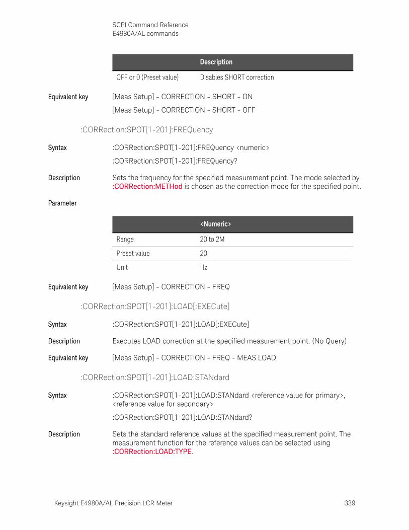
Keysight E4980A/AL Precision LCR Meter 339
SCPI Command ReferenceE4980A/AL commands
Equivalent key [Meas Setup] - CORRECTION - SHORT - ON
[Meas Setup] - CORRECTION - SHORT - OFF
:CORRection:SPOT[1-201]:FREQuency
Syntax :CORRection:SPOT[1-201]:FREQuency <numeric>
:CORRection:SPOT[1-201]:FREQuency?
Description Sets the frequency for the specified measurement point. The mode selected by :CORRection:METHod is chosen as the correction mode for the specified point.
Parameter
Equivalent key [Meas Setup] - CORRECTION - FREQ
:CORRection:SPOT[1-201]:LOAD[:EXECute]
Syntax :CORRection:SPOT[1-201]:LOAD[:EXECute]
Description Executes LOAD correction at the specified measurement point. (No Query)
Equivalent key [Meas Setup] - CORRECTION - FREQ - MEAS LOAD
:CORRection:SPOT[1-201]:LOAD:STANdard
Syntax :CORRection:SPOT[1-201]:LOAD:STANdard <reference value for primary>, <reference value for secondary>
:CORRection:SPOT[1-201]:LOAD:STANdard?
Description Sets the standard reference values at the specified measurement point. The measurement function for the reference values can be selected using :CORRection:LOAD:TYPE.
OFF or 0 (Preset value) Disables SHORT correction
Description
<Numeric>
Range 20 to 2M
Preset value 20
Unit Hz
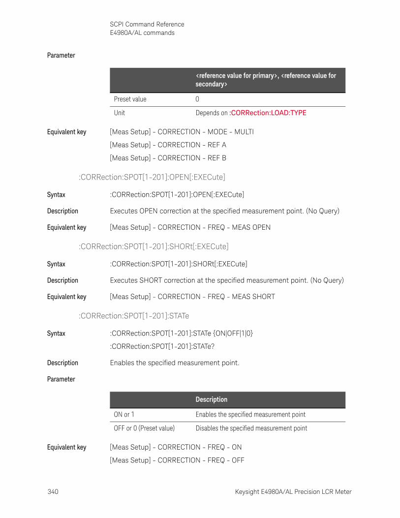
340 Keysight E4980A/AL Precision LCR Meter
SCPI Command ReferenceE4980A/AL commands
10-
Parameter
Equivalent key [Meas Setup] - CORRECTION - MODE - MULTI
[Meas Setup] - CORRECTION - REF A
[Meas Setup] - CORRECTION - REF B
:CORRection:SPOT[1-201]:OPEN[:EXECute]
Syntax :CORRection:SPOT[1-201]:OPEN[:EXECute]
Description Executes OPEN correction at the specified measurement point. (No Query)
Equivalent key [Meas Setup] - CORRECTION - FREQ - MEAS OPEN
:CORRection:SPOT[1-201]:SHORt[:EXECute]
Syntax :CORRection:SPOT[1-201]:SHORt[:EXECute]
Description Executes SHORT correction at the specified measurement point. (No Query)
Equivalent key [Meas Setup] - CORRECTION - FREQ - MEAS SHORT
:CORRection:SPOT[1-201]:STATe
Syntax :CORRection:SPOT[1-201]:STATe {ON|OFF|1|0}
:CORRection:SPOT[1-201]:STATe?
Description Enables the specified measurement point.
Parameter
Equivalent key [Meas Setup] - CORRECTION - FREQ - ON
[Meas Setup] - CORRECTION - FREQ - OFF
<reference value for primary>, <reference value for secondary>
Preset value 0
Unit Depends on :CORRection:LOAD:TYPE
Description
ON or 1 Enables the specified measurement point
OFF or 0 (Preset value) Disables the specified measurement point

Keysight E4980A/AL Precision LCR Meter 341
SCPI Command ReferenceE4980A/AL commands
:CORRection:USE[:CHANnel]
Syntax :CORRection:USE[:CHANnel] <channel>
:CORRection:USE[:CHANnel]?
Description Selects the channel number to be used for the Scanner I/F MULTI mode.
Parameter
Equivalent key [Meas Setup] - CORRECTION - CH
:CORRection:USE:DATA[:MULTi]
Syntax :CORRection:USE:DATA[:MULTi] <channel>,<open1 A>,<open1 B>,<short1 A>,<short1 B>,<load1 A>,<load1 B>,<open2 A>,<open2 B>,<short2 A>,<short2 B>,<load2 A>,<load2 B>,.......,<open 201A>,<open201 B>,<short201 A>,<short201 B>,<load201 A>,<load201 B>
:CORRection:USE:DATA[:MULTi]? <channel>
Description Sets or returns the open/short/load data for the “Multi” correction mode. The data for all 201 test points must be set. Any point with no correction data should be set to 0. A query will return 1,206 data for 201 test points even if there are some frequency points that were turned off. A value of 0 is returned when there are the no correction data.
Parameter
Example of Use Dim Result As String * 50000
<channel>
Range 0 to 127
Preset value 0
<channel>
Range 0 to 127
<open(n) A>, <open(n) B>, <short(n) A>, <short(n) B>, <load(n)A>, <load(n) B>
Preset value 0
Units OPEN: S; SHORT: ohms; LOAD: Depends on :CORRection:LOAD:TYPE
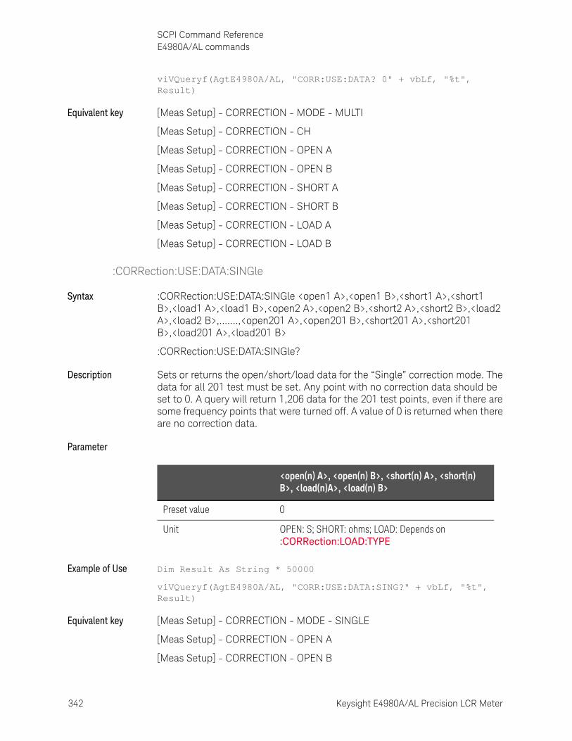
342 Keysight E4980A/AL Precision LCR Meter
SCPI Command ReferenceE4980A/AL commands
10-
viVQueryf(AgtE4980A/AL, "CORR:USE:DATA? 0" + vbLf, "%t", Result)
Equivalent key [Meas Setup] - CORRECTION - MODE - MULTI
[Meas Setup] - CORRECTION - CH
[Meas Setup] - CORRECTION - OPEN A
[Meas Setup] - CORRECTION - OPEN B
[Meas Setup] - CORRECTION - SHORT A
[Meas Setup] - CORRECTION - SHORT B
[Meas Setup] - CORRECTION - LOAD A
[Meas Setup] - CORRECTION - LOAD B
:CORRection:USE:DATA:SINGle
Syntax :CORRection:USE:DATA:SINGle <open1 A>,<open1 B>,<short1 A>,<short1 B>,<load1 A>,<load1 B>,<open2 A>,<open2 B>,<short2 A>,<short2 B>,<load2 A>,<load2 B>,.......,<open201 A>,<open201 B>,<short201 A>,<short201 B>,<load201 A>,<load201 B>
:CORRection:USE:DATA:SINGle?
Description Sets or returns the open/short/load data for the “Single” correction mode. The data for all 201 test must be set. Any point with no correction data should be set to 0. A query will return 1,206 data for the 201 test points, even if there are some frequency points that were turned off. A value of 0 is returned when there are no correction data.
Parameter
Example of Use Dim Result As String * 50000
viVQueryf(AgtE4980A/AL, "CORR:USE:DATA:SING?" + vbLf, "%t", Result)
Equivalent key [Meas Setup] - CORRECTION - MODE - SINGLE
[Meas Setup] - CORRECTION - OPEN A
[Meas Setup] - CORRECTION - OPEN B
<open(n) A>, <open(n) B>, <short(n) A>, <short(n) B>, <load(n)A>, <load(n) B>
Preset value 0
Unit OPEN: S; SHORT: ohms; LOAD: Depends on :CORRection:LOAD:TYPE
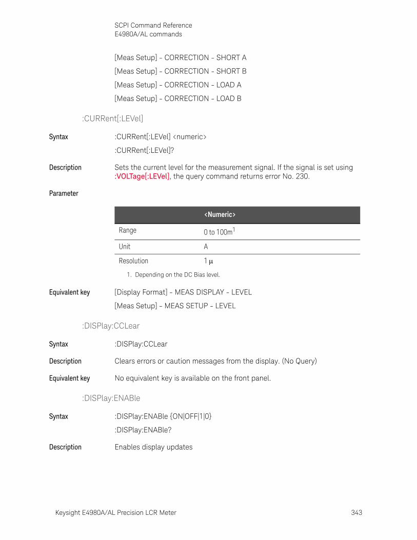
Keysight E4980A/AL Precision LCR Meter 343
SCPI Command ReferenceE4980A/AL commands
[Meas Setup] - CORRECTION - SHORT A
[Meas Setup] - CORRECTION - SHORT B
[Meas Setup] - CORRECTION - LOAD A
[Meas Setup] - CORRECTION - LOAD B
:CURRent[:LEVel]
Syntax :CURRent[:LEVel] <numeric>
:CURRent[:LEVel]?
Description Sets the current level for the measurement signal. If the signal is set using :VOLTage[:LEVel], the query command returns error No. 230.
Parameter
Equivalent key [Display Format] - MEAS DISPLAY - LEVEL
[Meas Setup] - MEAS SETUP - LEVEL
:DISPlay:CCLear
Syntax :DISPlay:CCLear
Description Clears errors or caution messages from the display. (No Query)
Equivalent key No equivalent key is available on the front panel.
:DISPlay:ENABle
Syntax :DISPlay:ENABle {ON|OFF|1|0}
:DISPlay:ENABle?
Description Enables display updates
<Numeric>
Range 0 to 100m1
Unit A
Resolution 1
1. Depending on the DC Bias level.
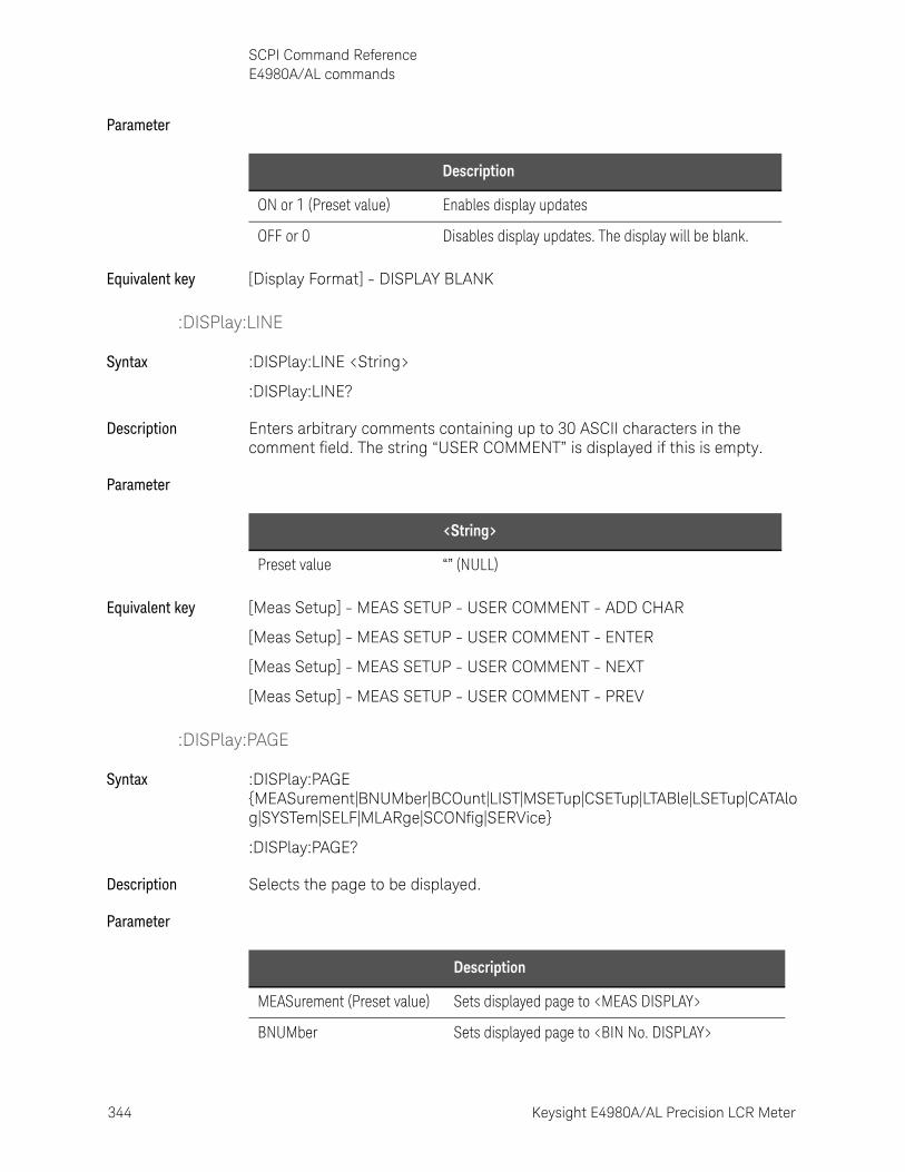
344 Keysight E4980A/AL Precision LCR Meter
SCPI Command ReferenceE4980A/AL commands
10-
Parameter
Equivalent key [Display Format] - DISPLAY BLANK
:DISPlay:LINE
Syntax :DISPlay:LINE <String>
:DISPlay:LINE?
Description Enters arbitrary comments containing up to 30 ASCII characters in the comment field. The string “USER COMMENT” is displayed if this is empty.
Parameter
Equivalent key [Meas Setup] - MEAS SETUP - USER COMMENT - ADD CHAR
[Meas Setup] - MEAS SETUP - USER COMMENT - ENTER
[Meas Setup] - MEAS SETUP - USER COMMENT - NEXT
[Meas Setup] - MEAS SETUP - USER COMMENT - PREV
:DISPlay:PAGE
Syntax :DISPlay:PAGE {MEASurement|BNUMber|BCOunt|LIST|MSETup|CSETup|LTABle|LSETup|CATAlog|SYSTem|SELF|MLARge|SCONfig|SERVice}
:DISPlay:PAGE?
Description Selects the page to be displayed.
Parameter
Description
ON or 1 (Preset value) Enables display updates
OFF or 0 Disables display updates. The display will be blank.
<String>
Preset value “” (NULL)
Description
MEASurement (Preset value) Sets displayed page to <MEAS DISPLAY>
BNUMber Sets displayed page to <BIN No. DISPLAY>
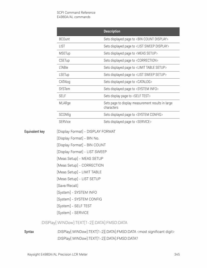
Keysight E4980A/AL Precision LCR Meter 345
SCPI Command ReferenceE4980A/AL commands
Equivalent key [Display Format] - DISPLAY FORMAT
[Display Format] - BIN No.
[Display Format] - BIN COUNT
[Display Format] - LIST SWEEP
[Meas Setup] - MEAS SETUP
[Meas Setup] - CORRECTION
[Meas Setup] - LIMIT TABLE
[Meas Setup] - LIST SETUP
[Save/Recall]
[System] - SYSTEM INFO
[System] - SYSTEM CONFIG
[System] - SELF TEST
[System] - SERVICE
:DISPlay[:WINDow]:TEXT[1-2][:DATA]:FMSD:DATA
Syntax :DISPlay[:WINDow]:TEXT[1-2][:DATA]:FMSD:DATA <most significant digit>
:DISPlay[:WINDow]:TEXT[1-2][:DATA]:FMSD:DATA?
BCOunt Sets displayed page to <BIN COUNT DISPLAY>
LIST Sets displayed page to <LIST SWEEP DISPLAY>
MSETup Sets displayed page to <MEAS SETUP>
CSETup Sets displayed page to <CORRECTION>
LTABle Sets displayed page to <LIMIT TABLE SETUP>
LSETup Sets displayed page to <LIST SWEEP SETUP>
CATAlog Sets displayed page to <CATALOG>
SYSTem Sets displayed page to <SYSTEM INFO>
SELF Sets display page to <SELF TEST>
MLARge Sets page to display measurement results in large characters
SCONfig Sets displayed page to <SYSTEM CONFIG>
SERVice Sets displayed page to <SERVICE>
Description
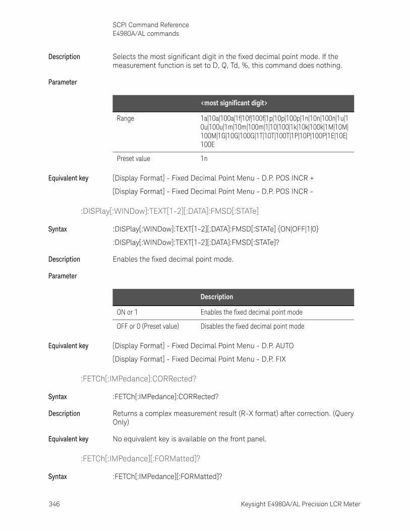
346 Keysight E4980A/AL Precision LCR Meter
SCPI Command ReferenceE4980A/AL commands
10-
Description Selects the most significant digit in the fixed decimal point mode. If the measurement function is set to D, Q, Td, %, this command does nothing.
Parameter
Equivalent key [Display Format] - Fixed Decimal Point Menu - D.P. POS INCR +
[Display Format] - Fixed Decimal Point Menu - D.P. POS INCR -
:DISPlay[:WINDow]:TEXT[1-2][:DATA]:FMSD[:STATe]
Syntax :DISPlay[:WINDow]:TEXT[1-2][:DATA]:FMSD[:STATe] {ON|OFF|1|0}
:DISPlay[:WINDow]:TEXT[1-2][:DATA]:FMSD[:STATe]?
Description Enables the fixed decimal point mode.
Parameter
Equivalent key [Display Format] - Fixed Decimal Point Menu - D.P. AUTO
[Display Format] - Fixed Decimal Point Menu - D.P. FIX
:FETCh[:IMPedance]:CORRected?
Syntax :FETCh[:IMPedance]:CORRected?
Description Returns a complex measurement result (R-X format) after correction. (Query Only)
Equivalent key No equivalent key is available on the front panel.
:FETCh[:IMPedance][:FORMatted]?
Syntax :FETCh[:IMPedance][:FORMatted]?
<most significant digit>
Range 1a|10a|100a|1f|10f|100f|1p|10p|100p|1n|10n|100n|1u|10u|100u|1m|10m|100m|1|10|100|1k|10k|100k|1M|10M|100M|1G|10G|100G|1T|10T|100T|1P|10P|100P|1E|10E|100E
Preset value 1n
Description
ON or 1 Enables the fixed decimal point mode
OFF or 0 (Preset value) Disables the fixed decimal point mode
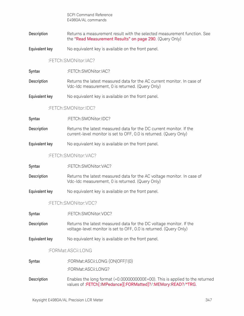
Keysight E4980A/AL Precision LCR Meter 347
SCPI Command ReferenceE4980A/AL commands
Description Returns a measurement result with the selected measurement function. See the “Read Measurement Results” on page 290. (Query Only)
Equivalent key No equivalent key is available on the front panel.
:FETCh:SMONitor:IAC?
Syntax :FETCh:SMONitor:IAC?
Description Returns the latest measured data for the AC current monitor. In case of Vdc-Idc measurement, 0 is returned. (Query Only)
Equivalent key No equivalent key is available on the front panel.
:FETCh:SMONitor:IDC?
Syntax :FETCh:SMONitor:IDC?
Description Returns the latest measured data for the DC current monitor. If the current-level monitor is set to OFF, 0.0 is returned. (Query Only)
Equivalent key No equivalent key is available on the front panel.
:FETCh:SMONitor:VAC?
Syntax :FETCh:SMONitor:VAC?
Description Returns the latest measured data for the AC voltage monitor. In case of Vdc-Idc measurement, 0 is returned. (Query Only)
Equivalent key No equivalent key is available on the front panel.
:FETCh:SMONitor:VDC?
Syntax :FETCh:SMONitor:VDC?
Description Returns the latest measured data for the DC voltage monitor. If the voltage-level monitor is set to OFF, 0.0 is returned. (Query Only)
Equivalent key No equivalent key is available on the front panel.
:FORMat:ASCii:LONG
Syntax :FORMat:ASCii:LONG {ON|OFF|1|0}
:FORMat:ASCii:LONG?
Description Enables the long format (+0.0000000000E+00). This is applied to the returned values of :FETCh[:IMPedance][:FORMatted]?/:MEMory:READ?/*TRG.
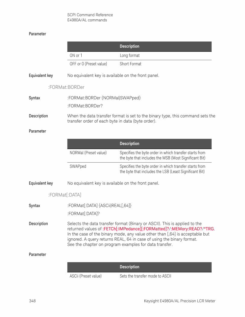
348 Keysight E4980A/AL Precision LCR Meter
SCPI Command ReferenceE4980A/AL commands
10-
Parameter
Equivalent key No equivalent key is available on the front panel.
:FORMat:BORDer
Syntax :FORMat:BORDer {NORMal|SWAPped}
:FORMat:BORDer?
Description When the data transfer format is set to the binary type, this command sets the transfer order of each byte in data (byte order).
Parameter
Equivalent key No equivalent key is available on the front panel.
:FORMat[:DATA]
Syntax :FORMat[:DATA] {ASCii|REAL[,64]}
:FORMat[:DATA]?
Description Selects the data transfer format (Binary or ASCII). This is applied to the returned values of :FETCh[:IMPedance][:FORMatted]?/:MEMory:READ?/*TRG. In the case of the binary mode, any value other than [,64] is acceptable but ignored. A query returns REAL, 64 in case of using the binary format.See the chapter on program examples for data transfer.
Parameter
Description
ON or 1 Long format
OFF or 0 (Preset value) Short Format
Description
NORMal (Preset value) Specifies the byte order in which transfer starts from the byte that includes the MSB (Most Significant Bit)
SWAPped Specifies the byte order in which transfer starts from the byte that includes the LSB (Least Significant Bit)
Description
ASCii (Preset value) Sets the transfer mode to ASCII
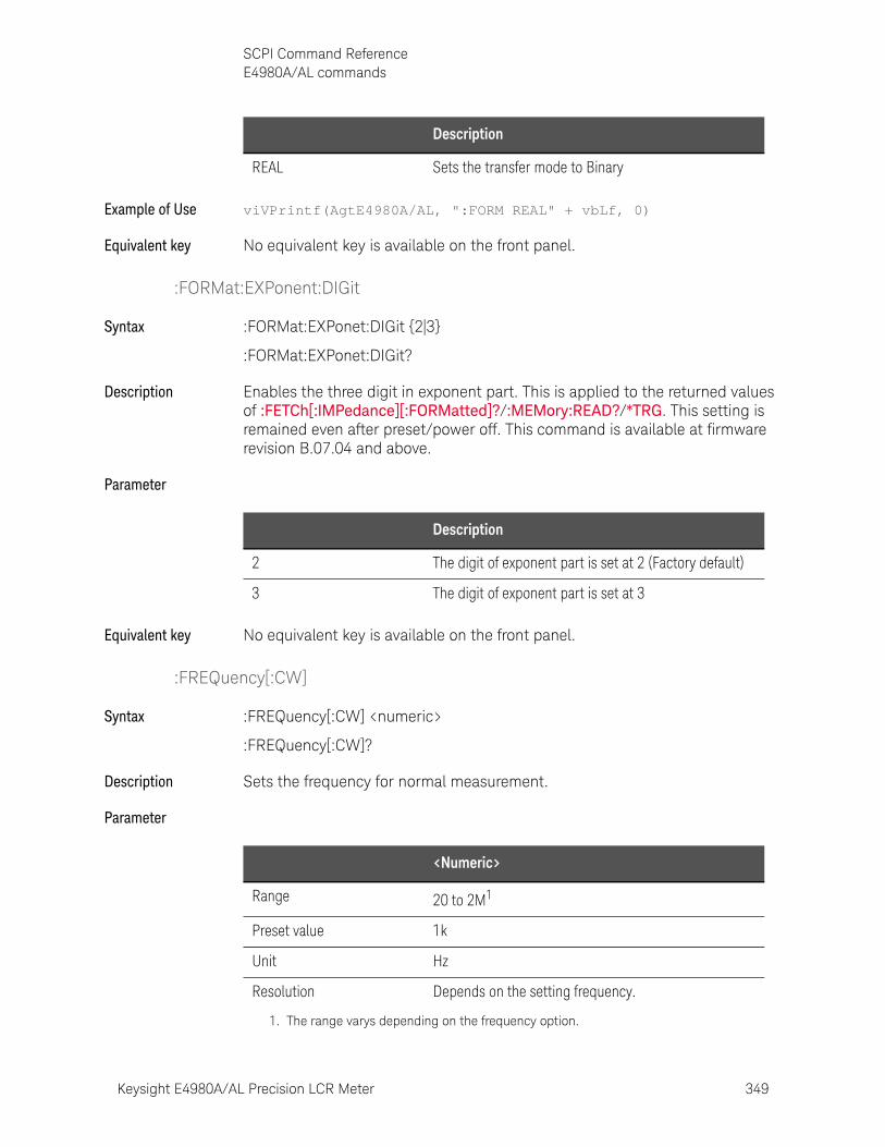
Keysight E4980A/AL Precision LCR Meter 349
SCPI Command ReferenceE4980A/AL commands
Example of Use viVPrintf(AgtE4980A/AL, ":FORM REAL" + vbLf, 0)
Equivalent key No equivalent key is available on the front panel.
:FORMat:EXPonent:DIGit
Syntax :FORMat:EXPonet:DIGit {2|3}
:FORMat:EXPonet:DIGit?
Description Enables the three digit in exponent part. This is applied to the returned values of :FETCh[:IMPedance][:FORMatted]?/:MEMory:READ?/*TRG. This setting is remained even after preset/power off. This command is available at firmware revision B.07.04 and above.
Parameter
Equivalent key No equivalent key is available on the front panel.
:FREQuency[:CW]
Syntax :FREQuency[:CW] <numeric>
:FREQuency[:CW]?
Description Sets the frequency for normal measurement.
Parameter
REAL Sets the transfer mode to Binary
Description
Description
2 The digit of exponent part is set at 2 (Factory default)
3 The digit of exponent part is set at 3
<Numeric>
Range 20 to 2M1
Preset value 1k
Unit Hz
Resolution Depends on the setting frequency.
1. The range varys depending on the frequency option.
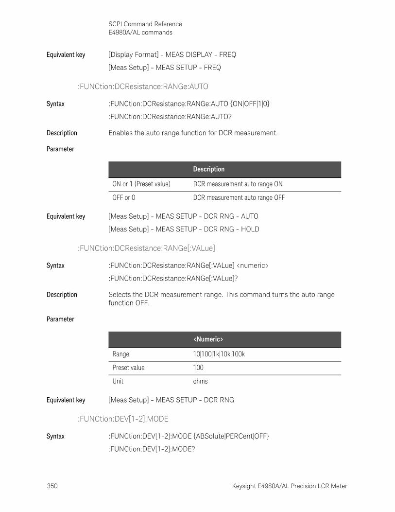
350 Keysight E4980A/AL Precision LCR Meter
SCPI Command ReferenceE4980A/AL commands
10-
Equivalent key [Display Format] - MEAS DISPLAY - FREQ
[Meas Setup] - MEAS SETUP - FREQ
:FUNCtion:DCResistance:RANGe:AUTO
Syntax :FUNCtion:DCResistance:RANGe:AUTO {ON|OFF|1|0}
:FUNCtion:DCResistance:RANGe:AUTO?
Description Enables the auto range function for DCR measurement.
Parameter
Equivalent key [Meas Setup] - MEAS SETUP - DCR RNG - AUTO
[Meas Setup] - MEAS SETUP - DCR RNG - HOLD
:FUNCtion:DCResistance:RANGe[:VALue]
Syntax :FUNCtion:DCResistance:RANGe[:VALue] <numeric>
:FUNCtion:DCResistance:RANGe[:VALue]?
Description Selects the DCR measurement range. This command turns the auto range function OFF.
Parameter
Equivalent key [Meas Setup] - MEAS SETUP - DCR RNG
:FUNCtion:DEV[1-2]:MODE
Syntax :FUNCtion:DEV[1-2]:MODE {ABSolute|PERCent|OFF}
:FUNCtion:DEV[1-2]:MODE?
Description
ON or 1 (Preset value) DCR measurement auto range ON
OFF or 0 DCR measurement auto range OFF
<Numeric>
Range 10|100|1k|10k|100k
Preset value 100
Unit ohms
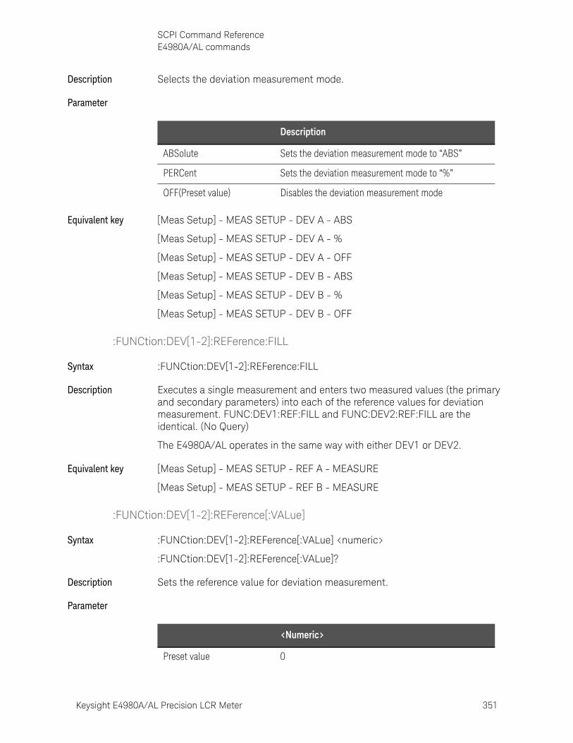
Keysight E4980A/AL Precision LCR Meter 351
SCPI Command ReferenceE4980A/AL commands
Description Selects the deviation measurement mode.
Parameter
Equivalent key [Meas Setup] - MEAS SETUP - DEV A - ABS
[Meas Setup] - MEAS SETUP - DEV A - %
[Meas Setup] - MEAS SETUP - DEV A - OFF
[Meas Setup] - MEAS SETUP - DEV B - ABS
[Meas Setup] - MEAS SETUP - DEV B - %
[Meas Setup] - MEAS SETUP - DEV B - OFF
:FUNCtion:DEV[1-2]:REFerence:FILL
Syntax :FUNCtion:DEV[1-2]:REFerence:FILL
Description Executes a single measurement and enters two measured values (the primary and secondary parameters) into each of the reference values for deviation measurement. FUNC:DEV1:REF:FILL and FUNC:DEV2:REF:FILL are the identical. (No Query)
The E4980A/AL operates in the same way with either DEV1 or DEV2.
Equivalent key [Meas Setup] - MEAS SETUP - REF A - MEASURE
[Meas Setup] - MEAS SETUP - REF B - MEASURE
:FUNCtion:DEV[1-2]:REFerence[:VALue]
Syntax :FUNCtion:DEV[1-2]:REFerence[:VALue] <numeric>
:FUNCtion:DEV[1-2]:REFerence[:VALue]?
Description Sets the reference value for deviation measurement.
Parameter
Description
ABSolute Sets the deviation measurement mode to “ABS”
PERCent Sets the deviation measurement mode to “%”
OFF(Preset value) Disables the deviation measurement mode
<Numeric>
Preset value 0
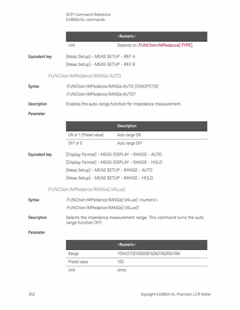
352 Keysight E4980A/AL Precision LCR Meter
SCPI Command ReferenceE4980A/AL commands
10-
Equivalent key [Meas Setup] - MEAS SETUP - REF A
[Meas Setup] - MEAS SETUP - REF B
:FUNCtion:IMPedance:RANGe:AUTO
Syntax :FUNCtion:IMPedance:RANGe:AUTO {ON|OFF|1|0}
:FUNCtion:IMPedance:RANGe:AUTO?
Description Enables the auto-range function for impedance measurement.
Parameter
Equivalent key [Display Format] - MEAS DISPLAY - RANGE - AUTO
[Display Format] - MEAS DISPLAY - RANGE - HOLD
[Meas Setup] - MEAS SETUP - RANGE - AUTO
[Meas Setup] - MEAS SETUP - RANGE - HOLD
:FUNCtion:IMPedance:RANGe[:VALue]
Syntax :FUNCtion:IMPedance:RANGe[:VALue] <numeric>
:FUNCtion:IMPedance:RANGe[:VALue]?
Description Selects the impedance measurement range. This command turns the auto range function OFF.
Parameter
Unit Depends on :FUNCtion:IMPedance[:TYPE].
<Numeric>
Description
ON or 1 (Preset value) Auto range ON
OFF or 0 Auto range OFF
<Numeric>
Range 100m|1|10|100|300|1k|3k|10k|30k|100k
Preset value 100
Unit ohms
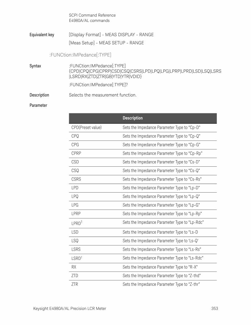
Keysight E4980A/AL Precision LCR Meter 353
SCPI Command ReferenceE4980A/AL commands
Equivalent key [Display Format] - MEAS DISPLAY - RANGE
[Meas Setup] - MEAS SETUP - RANGE
:FUNCtion:IMPedance[:TYPE]
Syntax :FUNCtion:IMPedance[:TYPE] {CPD|CPQ|CPG|CPRP|CSD|CSQ|CSRS|LPD|LPQ|LPG|LPRP|LPRD|LSD|LSQ|LSRS|LSRD|RX|ZTD|ZTR|GB|YTD|YTR|VDID}
:FUNCtion:IMPedance[:TYPE]?
Description Selects the measurement function.
Parameter
Description
CPD(Preset value) Sets the Impedance Parameter Type to “Cp-D”
CPQ Sets the Impedance Parameter Type to “Cp-Q”
CPG Sets the Impedance Parameter Type to “Cp-G”
CPRP Sets the Impedance Parameter Type to “Cp-Rp”
CSD Sets the Impedance Parameter Type to “Cs-D”
CSQ Sets the Impedance Parameter Type to “Cs-Q”
CSRS Sets the Impedance Parameter Type to “Cs-Rs”
LPD Sets the Impedance Parameter Type to “Lp-D”
LPQ Sets the Impedance Parameter Type to “Lp-Q”
LPG Sets the Impedance Parameter Type to “Lp-G”
LPRP Sets the Impedance Parameter Type to “Lp-Rp”
LPRD1 Sets the Impedance Parameter Type to “Lp-Rdc”
LSD Sets the Impedance Parameter Type to “Ls-D
LSQ Sets the Impedance Parameter Type to 'Ls-Q'
LSRS Sets the Impedance Parameter Type to “Ls-Rs”
LSRD1 Sets the Impedance Parameter Type to “Ls-Rdc”
RX Sets the Impedance Parameter Type to “R-X”
ZTD Sets the Impedance Parameter Type to “Z-thd”
ZTR Sets the Impedance Parameter Type to “Z-thr”
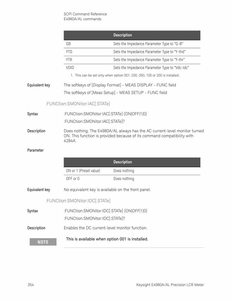
354 Keysight E4980A/AL Precision LCR Meter
SCPI Command ReferenceE4980A/AL commands
10-
Equivalent key The softkeys of [Display Format] - MEAS DISPLAY - FUNC field
The softkeys of [Meas Setup] - MEAS SETUP - FUNC field
:FUNCtion:SMONitor:IAC[:STATe]
Syntax :FUNCtion:SMONitor:IAC[:STATe] {ON|OFF|1|0}
:FUNCtion:SMONitor:IAC[:STATe]?
Description Does nothing. The E4980A/AL always has the AC current-level monitor turned ON. This function is provided because of its command compatibility with 4284A.
Parameter
Equivalent key No equivalent key is available on the front panel.
:FUNCtion:SMONitor:IDC[:STATe]
Syntax :FUNCtion:SMONitor:IDC[:STATe] {ON|OFF|1|0}
:FUNCtion:SMONitor:IDC[:STATe]?
Description Enables the DC current-level monitor function.
GB Sets the Impedance Parameter Type to “G-B”
YTD Sets the Impedance Parameter Type to “Y-thd”
YTR Sets the Impedance Parameter Type to “Y-thr”
VDID Sets the Impedance Parameter Type to “Vdc-Idc”
1. This can be set only when option 001, 030, 050, 100 or 200 is installed.
Description
Description
ON or 1 (Preset value) Does nothing
OFF or 0 Does nothing
This is available when option 001 is installed.
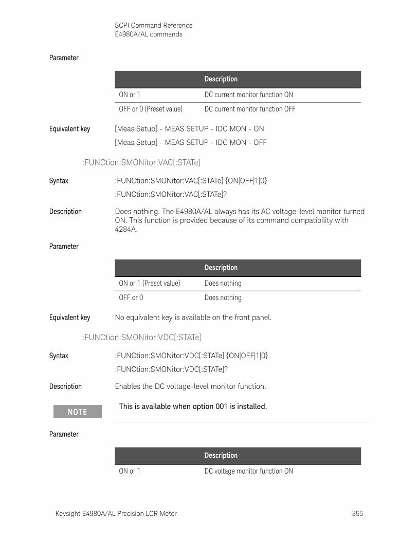
Keysight E4980A/AL Precision LCR Meter 355
SCPI Command ReferenceE4980A/AL commands
Parameter
Equivalent key [Meas Setup] - MEAS SETUP - IDC MON - ON
[Meas Setup] - MEAS SETUP - IDC MON - OFF
:FUNCtion:SMONitor:VAC[:STATe]
Syntax :FUNCtion:SMONitor:VAC[:STATe] {ON|OFF|1|0}
:FUNCtion:SMONitor:VAC[:STATe]?
Description Does nothing. The E4980A/AL always has its AC voltage-level monitor turned ON. This function is provided because of its command compatibility with 4284A.
Parameter
Equivalent key No equivalent key is available on the front panel.
:FUNCtion:SMONitor:VDC[:STATe]
Syntax :FUNCtion:SMONitor:VDC[:STATe] {ON|OFF|1|0}
:FUNCtion:SMONitor:VDC[:STATe]?
Description Enables the DC voltage-level monitor function.
Parameter
Description
ON or 1 DC current monitor function ON
OFF or 0 (Preset value) DC current monitor function OFF
Description
ON or 1 (Preset value) Does nothing
OFF or 0 Does nothing
This is available when option 001 is installed.
Description
ON or 1 DC voltage monitor function ON
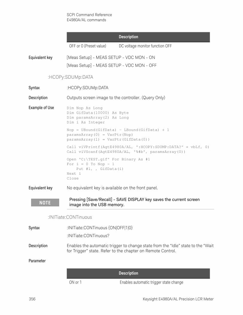
356 Keysight E4980A/AL Precision LCR Meter
SCPI Command ReferenceE4980A/AL commands
10-
Equivalent key [Meas Setup] - MEAS SETUP - VDC MON - ON
[Meas Setup] - MEAS SETUP - VDC MON - OFF
:HCOPy:SDUMp:DATA
Syntax :HCOPy:SDUMp:DATA
Description Outputs screen image to the controller. (Query Only)
Example of Use Dim Nop As LongDim GifData(10000) As ByteDim paramsArray(2) As LongDim i As Integer
Nop = UBound(GifData) - LBound(GifData) + 1paramsArray(0) = VarPtr(Nop)paramsArray(1) = VarPtr(GifData(0))
Call viVPrintf(AgtE4980A/AL, ":HCOPY:SDUMP:DATA?" + vbLf, 0)Call viVScanf(AgtE4980A/AL, "%#b", paramsArray(0))
Open "C:\TEST.gif" For Binary As #1For i = 0 To Nop - 1 Put #1, , GifData(i)Next iClose
Equivalent key No equivalent key is available on the front panel.
:INITiate:CONTinuous
Syntax :INITiate:CONTinuous {ON|OFF|1|0}
:INITiate:CONTinuous?
Description Enables the automatic trigger to change state from the “Idle” state to the “Wait for Trigger” state. Refer to the chapter on Remote Control.
Parameter
OFF or 0 (Preset value) DC voltage monitor function OFF
Description
Pressing [Save/Recall] - SAVE DISPLAY key saves the current screen image into the USB memory.
Description
ON or 1 Enables automatic trigger state change
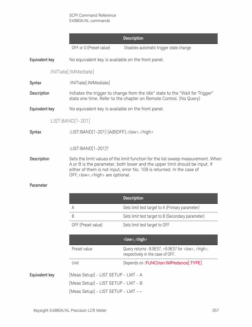
Keysight E4980A/AL Precision LCR Meter 357
SCPI Command ReferenceE4980A/AL commands
Equivalent key No equivalent key is available on the front panel.
:INITiate[:IMMediate]
Syntax :INITiate[:IMMediate]
Description Initiates the trigger to change from the Idle” state to the “Wait for Trigger” state one time. Refer to the chapter on Remote Control. (No Query)
Equivalent key No equivalent key is available on the front panel.
:LIST:BAND[1-201]
Syntax :LIST:BAND[1-201] {A|B|OFF},<low>,<high>
:LIST:BAND[1-201]?
Description Sets the limit values of the limit function for the list sweep measurement. When A or B is the parameter, both lower and the upper limit should be input. If either of them is not input, error No. 109 is returned. In the case of OFF,<low>,<high> are optional.
Parameter
Equivalent key [Meas Setup] - LIST SETUP - LMT - A
[Meas Setup] - LIST SETUP - LMT - B
[Meas Setup] - LIST SETUP - LMT -
OFF or 0 (Preset value) Disables automatic trigger state change
Description
Description
A Sets limit test target to A (Primary parameter)
B Sets limit test target to B (Secondary parameter)
OFF (Preset value) Sets limit test target to OFF
<low>,<high>
Preset value Query returns -9.9E37, +9.9E37 for <low>, <high>, respectively in the case of OFF.
Unit Depends on :FUNCtion:IMPedance[:TYPE]
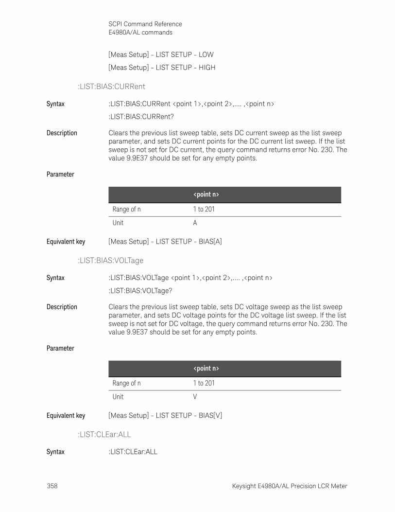
358 Keysight E4980A/AL Precision LCR Meter
SCPI Command ReferenceE4980A/AL commands
10-
[Meas Setup] - LIST SETUP - LOW
[Meas Setup] - LIST SETUP - HIGH
:LIST:BIAS:CURRent
Syntax :LIST:BIAS:CURRent <point 1>,<point 2>,.... ,<point n>
:LIST:BIAS:CURRent?
Description Clears the previous list sweep table, sets DC current sweep as the list sweep parameter, and sets DC current points for the DC current list sweep. If the list sweep is not set for DC current, the query command returns error No. 230. The value 9.9E37 should be set for any empty points.
Parameter
Equivalent key [Meas Setup] - LIST SETUP - BIAS[A]
:LIST:BIAS:VOLTage
Syntax :LIST:BIAS:VOLTage <point 1>,<point 2>,.... ,<point n>
:LIST:BIAS:VOLTage?
Description Clears the previous list sweep table, sets DC voltage sweep as the list sweep parameter, and sets DC voltage points for the DC voltage list sweep. If the list sweep is not set for DC voltage, the query command returns error No. 230. The value 9.9E37 should be set for any empty points.
Parameter
Equivalent key [Meas Setup] - LIST SETUP - BIAS[V]
:LIST:CLEar:ALL
Syntax :LIST:CLEar:ALL
<point n>
Range of n 1 to 201
Unit A
<point n>
Range of n 1 to 201
Unit V
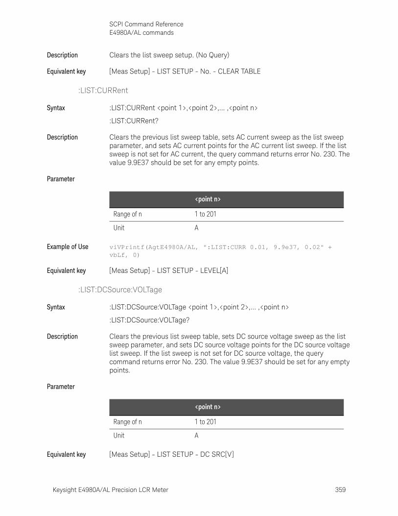
Keysight E4980A/AL Precision LCR Meter 359
SCPI Command ReferenceE4980A/AL commands
Description Clears the list sweep setup. (No Query)
Equivalent key [Meas Setup] - LIST SETUP - No. - CLEAR TABLE
:LIST:CURRent
Syntax :LIST:CURRent <point 1>,<point 2>,... ,<point n>
:LIST:CURRent?
Description Clears the previous list sweep table, sets AC current sweep as the list sweep parameter, and sets AC current points for the AC current list sweep. If the list sweep is not set for AC current, the query command returns error No. 230. The value 9.9E37 should be set for any empty points.
Parameter
Example of Use viVPrintf(AgtE4980A/AL, ":LIST:CURR 0.01, 9.9e37, 0.02" + vbLf, 0)
Equivalent key [Meas Setup] - LIST SETUP - LEVEL[A]
:LIST:DCSource:VOLTage
Syntax :LIST:DCSource:VOLTage <point 1>,<point 2>,... ,<point n>
:LIST:DCSource:VOLTage?
Description Clears the previous list sweep table, sets DC source voltage sweep as the list sweep parameter, and sets DC source voltage points for the DC source voltage list sweep. If the list sweep is not set for DC source voltage, the query command returns error No. 230. The value 9.9E37 should be set for any empty points.
Parameter
Equivalent key [Meas Setup] - LIST SETUP - DC SRC[V]
<point n>
Range of n 1 to 201
Unit A
<point n>
Range of n 1 to 201
Unit A
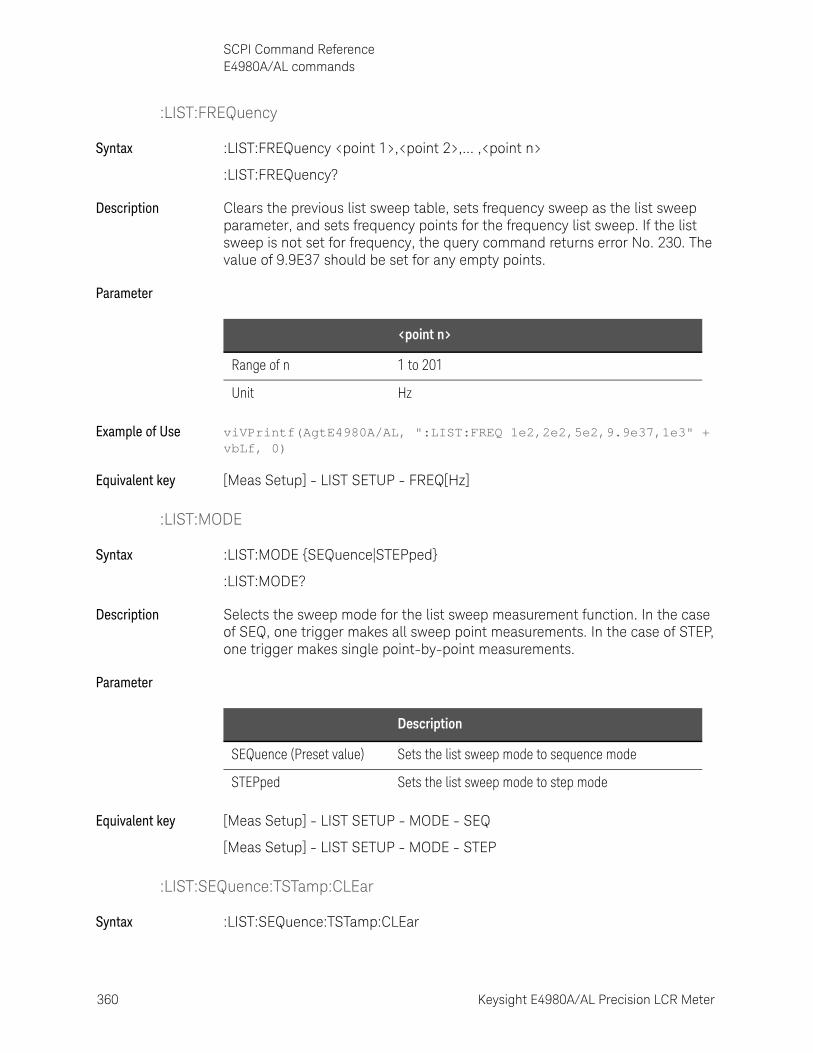
360 Keysight E4980A/AL Precision LCR Meter
SCPI Command ReferenceE4980A/AL commands
10-
:LIST:FREQuency
Syntax :LIST:FREQuency <point 1>,<point 2>,... ,<point n>
:LIST:FREQuency?
Description Clears the previous list sweep table, sets frequency sweep as the list sweep parameter, and sets frequency points for the frequency list sweep. If the list sweep is not set for frequency, the query command returns error No. 230. The value of 9.9E37 should be set for any empty points.
Parameter
Example of Use viVPrintf(AgtE4980A/AL, ":LIST:FREQ 1e2,2e2,5e2,9.9e37,1e3" + vbLf, 0)
Equivalent key [Meas Setup] - LIST SETUP - FREQ[Hz]
:LIST:MODE
Syntax :LIST:MODE {SEQuence|STEPped}
:LIST:MODE?
Description Selects the sweep mode for the list sweep measurement function. In the case of SEQ, one trigger makes all sweep point measurements. In the case of STEP, one trigger makes single point-by-point measurements.
Parameter
Equivalent key [Meas Setup] - LIST SETUP - MODE - SEQ
[Meas Setup] - LIST SETUP - MODE - STEP
:LIST:SEQuence:TSTamp:CLEar
Syntax :LIST:SEQuence:TSTamp:CLEar
<point n>
Range of n 1 to 201
Unit Hz
Description
SEQuence (Preset value) Sets the list sweep mode to sequence mode
STEPped Sets the list sweep mode to step mode
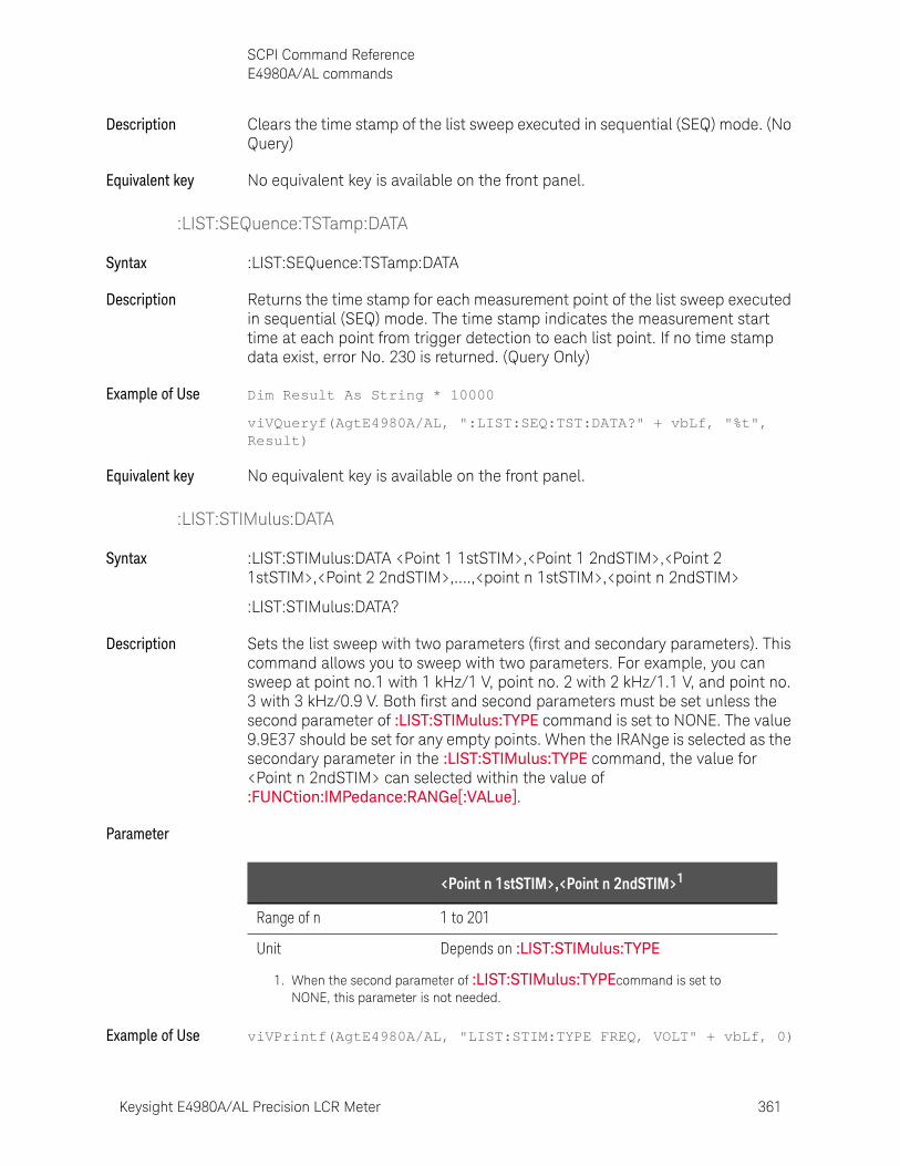
Keysight E4980A/AL Precision LCR Meter 361
SCPI Command ReferenceE4980A/AL commands
Description Clears the time stamp of the list sweep executed in sequential (SEQ) mode. (No Query)
Equivalent key No equivalent key is available on the front panel.
:LIST:SEQuence:TSTamp:DATA
Syntax :LIST:SEQuence:TSTamp:DATA
Description Returns the time stamp for each measurement point of the list sweep executed in sequential (SEQ) mode. The time stamp indicates the measurement start time at each point from trigger detection to each list point. If no time stamp data exist, error No. 230 is returned. (Query Only)
Example of Use Dim Result As String * 10000
viVQueryf(AgtE4980A/AL, ":LIST:SEQ:TST:DATA?" + vbLf, "%t", Result)
Equivalent key No equivalent key is available on the front panel.
:LIST:STIMulus:DATA
Syntax :LIST:STIMulus:DATA <Point 1 1stSTIM>,<Point 1 2ndSTIM>,<Point 2 1stSTIM>,<Point 2 2ndSTIM>,....,<point n 1stSTIM>,<point n 2ndSTIM>
:LIST:STIMulus:DATA?
Description Sets the list sweep with two parameters (first and secondary parameters). This command allows you to sweep with two parameters. For example, you can sweep at point no.1 with 1 kHz/1 V, point no. 2 with 2 kHz/1.1 V, and point no. 3 with 3 kHz/0.9 V. Both first and second parameters must be set unless the second parameter of :LIST:STIMulus:TYPE command is set to NONE. The value 9.9E37 should be set for any empty points. When the IRANge is selected as the secondary parameter in the :LIST:STIMulus:TYPE command, the value for <Point n 2ndSTIM> can selected within the value of :FUNCtion:IMPedance:RANGe[:VALue].
Parameter
Example of Use viVPrintf(AgtE4980A/AL, "LIST:STIM:TYPE FREQ, VOLT" + vbLf, 0)
<Point n 1stSTIM>,<Point n 2ndSTIM>1
Range of n 1 to 201
Unit Depends on :LIST:STIMulus:TYPE
1. When the second parameter of :LIST:STIMulus:TYPEcommand is set to NONE, this parameter is not needed.
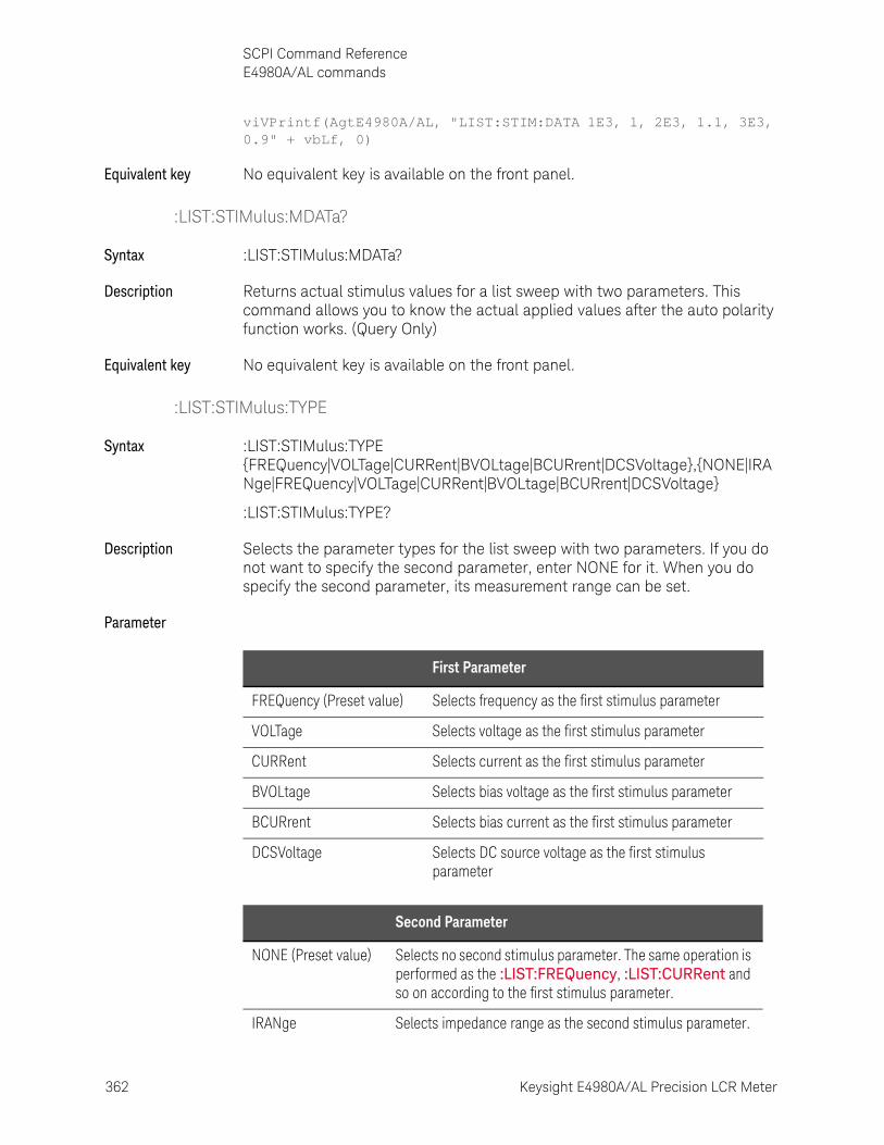
362 Keysight E4980A/AL Precision LCR Meter
SCPI Command ReferenceE4980A/AL commands
10-
viVPrintf(AgtE4980A/AL, "LIST:STIM:DATA 1E3, 1, 2E3, 1.1, 3E3, 0.9" + vbLf, 0)
Equivalent key No equivalent key is available on the front panel.
:LIST:STIMulus:MDATa?
Syntax :LIST:STIMulus:MDATa?
Description Returns actual stimulus values for a list sweep with two parameters. This command allows you to know the actual applied values after the auto polarity function works. (Query Only)
Equivalent key No equivalent key is available on the front panel.
:LIST:STIMulus:TYPE
Syntax :LIST:STIMulus:TYPE {FREQuency|VOLTage|CURRent|BVOLtage|BCURrent|DCSVoltage},{NONE|IRANge|FREQuency|VOLTage|CURRent|BVOLtage|BCURrent|DCSVoltage}
:LIST:STIMulus:TYPE?
Description Selects the parameter types for the list sweep with two parameters. If you do not want to specify the second parameter, enter NONE for it. When you do specify the second parameter, its measurement range can be set.
Parameter
First Parameter
FREQuency (Preset value) Selects frequency as the first stimulus parameter
VOLTage Selects voltage as the first stimulus parameter
CURRent Selects current as the first stimulus parameter
BVOLtage Selects bias voltage as the first stimulus parameter
BCURrent Selects bias current as the first stimulus parameter
DCSVoltage Selects DC source voltage as the first stimulus parameter
Second Parameter
NONE (Preset value) Selects no second stimulus parameter. The same operation is performed as the :LIST:FREQuency, :LIST:CURRent and so on according to the first stimulus parameter.
IRANge Selects impedance range as the second stimulus parameter.
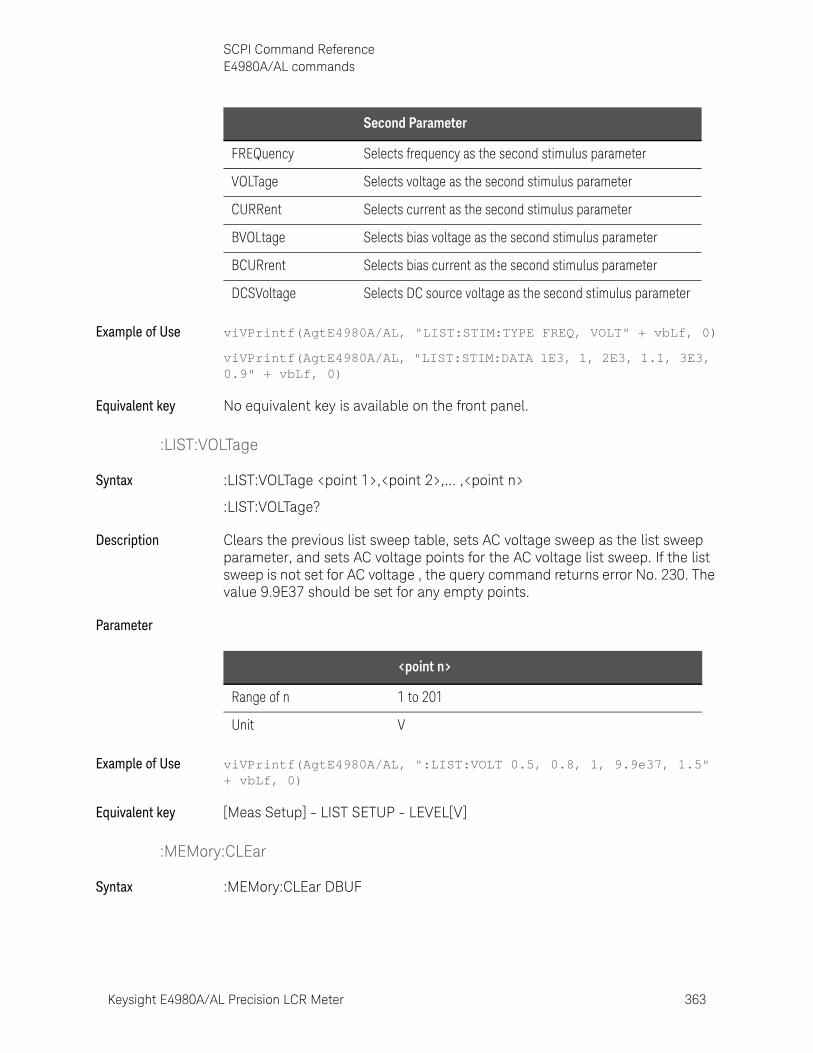
Keysight E4980A/AL Precision LCR Meter 363
SCPI Command ReferenceE4980A/AL commands
Example of Use viVPrintf(AgtE4980A/AL, "LIST:STIM:TYPE FREQ, VOLT" + vbLf, 0)
viVPrintf(AgtE4980A/AL, "LIST:STIM:DATA 1E3, 1, 2E3, 1.1, 3E3, 0.9" + vbLf, 0)
Equivalent key No equivalent key is available on the front panel.
:LIST:VOLTage
Syntax :LIST:VOLTage <point 1>,<point 2>,... ,<point n>
:LIST:VOLTage?
Description Clears the previous list sweep table, sets AC voltage sweep as the list sweep parameter, and sets AC voltage points for the AC voltage list sweep. If the list sweep is not set for AC voltage , the query command returns error No. 230. The value 9.9E37 should be set for any empty points.
Parameter
Example of Use viVPrintf(AgtE4980A/AL, ":LIST:VOLT 0.5, 0.8, 1, 9.9e37, 1.5" + vbLf, 0)
Equivalent key [Meas Setup] - LIST SETUP - LEVEL[V]
:MEMory:CLEar
Syntax :MEMory:CLEar DBUF
FREQuency Selects frequency as the second stimulus parameter
VOLTage Selects voltage as the second stimulus parameter
CURRent Selects current as the second stimulus parameter
BVOLtage Selects bias voltage as the second stimulus parameter
BCURrent Selects bias current as the second stimulus parameter
DCSVoltage Selects DC source voltage as the second stimulus parameter
Second Parameter
<point n>
Range of n 1 to 201
Unit V

364 Keysight E4980A/AL Precision LCR Meter
SCPI Command ReferenceE4980A/AL commands
10-
Description Clears and disables the data buffer memory. After this command is executed, measurement data will not be stored in the data buffer memory until execution of the :FILL command. (No Query)
Equivalent key [Save/Recall] - SAVE DATA - SAVE & STOP
This key is a combination of both :MEMory:READ? and :MEMory:CLEar.
:MEMory:DIM
Syntax :MEMory:DIM DBUF,<numeric>
:MEMory:DIM?
Description Clears the data buffer memory, and sets the data buffer memory’s size. An example of data buffer memory is shown in the chapter on program examples.
Parameter
Equivalent key No equivalent key is available on the front panel.
:MEMory:FILL
Syntax :MEMory:FILL DBUF
Description Enables the data buffer memory to store measurement data. After execution of this command, all measurement data will be stored in the data buffer memory. If this has already been enabled, this command will do nothing. (No Query)
Equivalent key [Save/Recall] - SAVE DATA - START LOG
:MEMory:READ?
Syntax :MEMory:READ? DBUF
Description Places the data in the data buffer memory into the output buffer. The output format of this command is the same as the one for FETC:IMP?. In the preset state, “9.90000E+37,+9.90000E+37,-1,+0” is returned the number of times specified by :MEMory:DIM. When the data buffer memory is not filled to the specified size (specified by the :MEMory:DIM command), “9.90000E+37,+9.90000E+37,-1,+0” remains for the rest of the data locations. (Query Only)
<Numeric>
Range 1 to 201
Preset value 201
Resolution 1
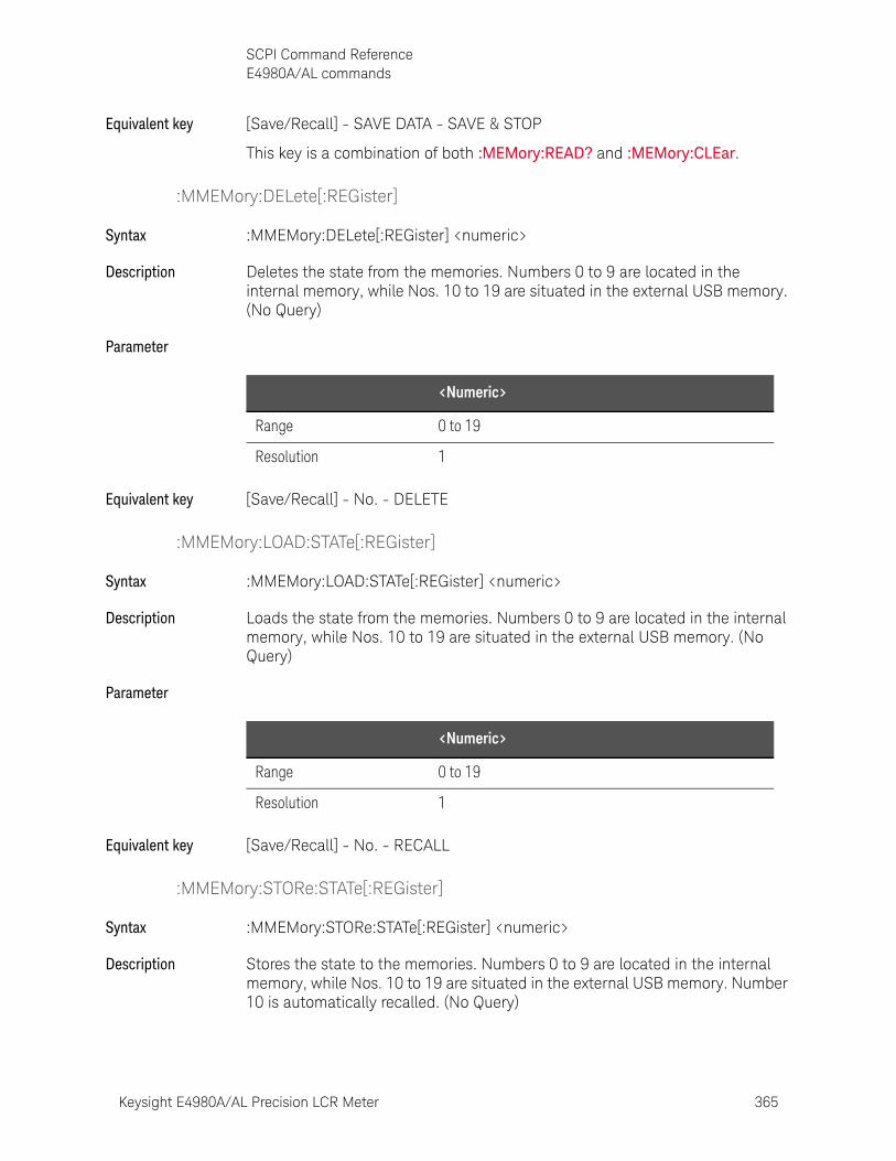
Keysight E4980A/AL Precision LCR Meter 365
SCPI Command ReferenceE4980A/AL commands
Equivalent key [Save/Recall] - SAVE DATA - SAVE & STOP
This key is a combination of both :MEMory:READ? and :MEMory:CLEar.
:MMEMory:DELete[:REGister]
Syntax :MMEMory:DELete[:REGister] <numeric>
Description Deletes the state from the memories. Numbers 0 to 9 are located in the internal memory, while Nos. 10 to 19 are situated in the external USB memory. (No Query)
Parameter
Equivalent key [Save/Recall] - No. - DELETE
:MMEMory:LOAD:STATe[:REGister]
Syntax :MMEMory:LOAD:STATe[:REGister] <numeric>
Description Loads the state from the memories. Numbers 0 to 9 are located in the internal memory, while Nos. 10 to 19 are situated in the external USB memory. (No Query)
Parameter
Equivalent key [Save/Recall] - No. - RECALL
:MMEMory:STORe:STATe[:REGister]
Syntax :MMEMory:STORe:STATe[:REGister] <numeric>
Description Stores the state to the memories. Numbers 0 to 9 are located in the internal memory, while Nos. 10 to 19 are situated in the external USB memory. Number 10 is automatically recalled. (No Query)
<Numeric>
Range 0 to 19
Resolution 1
<Numeric>
Range 0 to 19
Resolution 1

366 Keysight E4980A/AL Precision LCR Meter
SCPI Command ReferenceE4980A/AL commands
10-
Parameter
Equivalent key [Save/Recall] - No. - SAVE
:OUTPut:DC:ISOLation:LEVel:AUTO
Syntax :OUTPut:DC:ISOLation:LEVel:AUTO {ON|OFF|1|0}
:OUTPut:DC:ISOLation:LEVel:AUTO?
Description Enables the auto range function for DCI.
Parameter
Equivalent key [Meas Setup] - MEAS SETUP - DCI RNG - AUTO
[Meas Setup] - MEAS SETUP - DCI RNG - HOLD
:OUTPut:DC:ISOLation:LEVel:VALue
Syntax :OUTPut:DC:ISOLation:LEVel:VALue <numeric>
:OUTPut:DC:ISOLation:LEVel:VALue?
Description Selects DC isolation range. This command turns the auto range function OFF.
Parameter
Equivalent key [Meas Setup] - MEAS SETUP - DCI RNG
<Numeric>
Range 0 to 19
Resolution 1
Description
ON or 1 (Preset value) Enables the auto range function for DCI
OFF or 0 Disables the auto range function for DCI
<Numeric>
Range 20 |200 |2 m|20 m|100 m
Preset value 20 m
Unit A
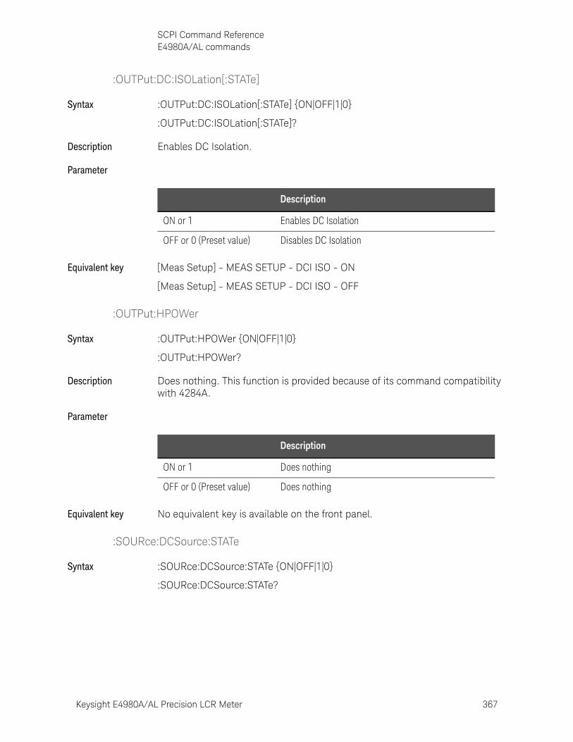
Keysight E4980A/AL Precision LCR Meter 367
SCPI Command ReferenceE4980A/AL commands
:OUTPut:DC:ISOLation[:STATe]
Syntax :OUTPut:DC:ISOLation[:STATe] {ON|OFF|1|0}
:OUTPut:DC:ISOLation[:STATe]?
Description Enables DC Isolation.
Parameter
Equivalent key [Meas Setup] - MEAS SETUP - DCI ISO - ON
[Meas Setup] - MEAS SETUP - DCI ISO - OFF
:OUTPut:HPOWer
Syntax :OUTPut:HPOWer {ON|OFF|1|0}
:OUTPut:HPOWer?
Description Does nothing. This function is provided because of its command compatibility with 4284A.
Parameter
Equivalent key No equivalent key is available on the front panel.
:SOURce:DCSource:STATe
Syntax :SOURce:DCSource:STATe {ON|OFF|1|0}
:SOURce:DCSource:STATe?
Description
ON or 1 Enables DC Isolation
OFF or 0 (Preset value) Disables DC Isolation
Description
ON or 1 Does nothing
OFF or 0 (Preset value) Does nothing
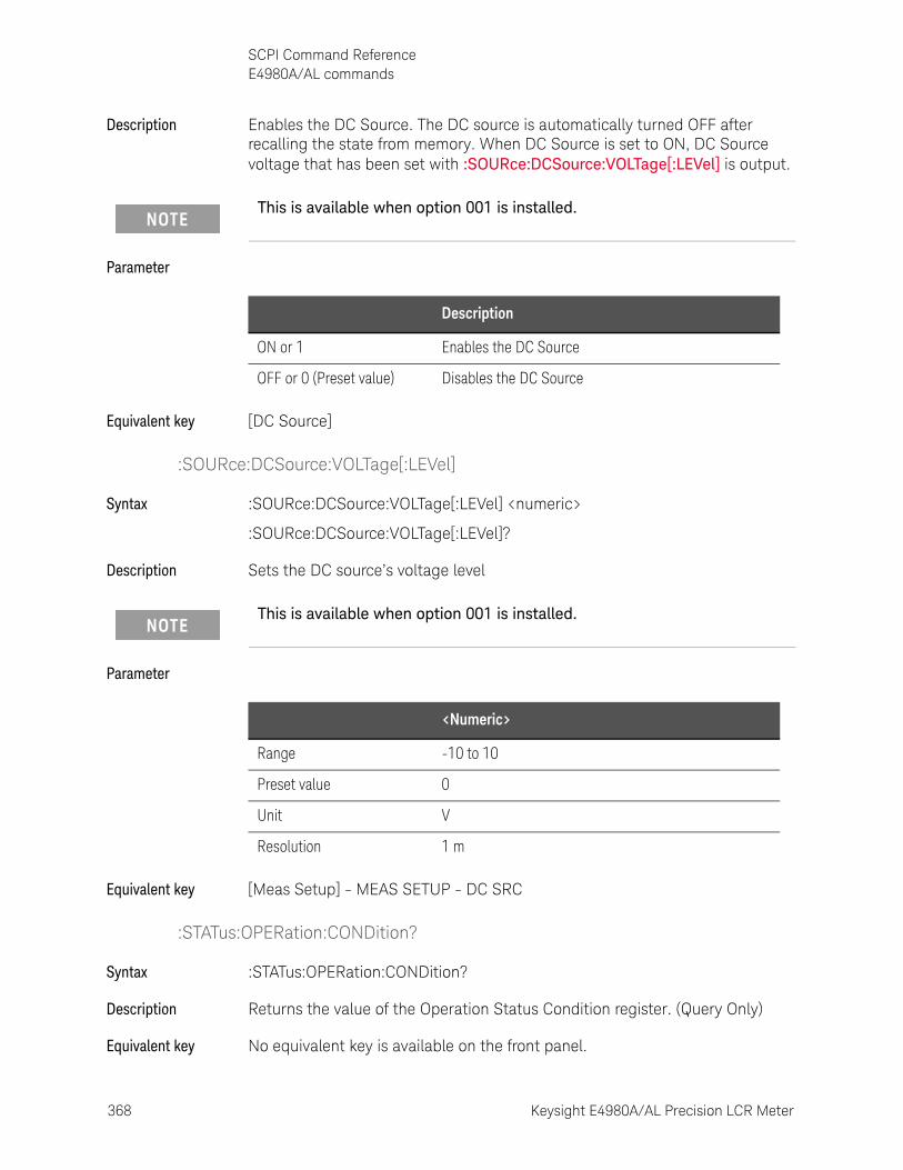
368 Keysight E4980A/AL Precision LCR Meter
SCPI Command ReferenceE4980A/AL commands
10-
Description Enables the DC Source. The DC source is automatically turned OFF after recalling the state from memory. When DC Source is set to ON, DC Source voltage that has been set with :SOURce:DCSource:VOLTage[:LEVel] is output.
Parameter
Equivalent key [DC Source]
:SOURce:DCSource:VOLTage[:LEVel]
Syntax :SOURce:DCSource:VOLTage[:LEVel] <numeric>
:SOURce:DCSource:VOLTage[:LEVel]?
Description Sets the DC source’s voltage level
Parameter
Equivalent key [Meas Setup] - MEAS SETUP - DC SRC
:STATus:OPERation:CONDition?
Syntax :STATus:OPERation:CONDition?
Description Returns the value of the Operation Status Condition register. (Query Only)
Equivalent key No equivalent key is available on the front panel.
This is available when option 001 is installed.
Description
ON or 1 Enables the DC Source
OFF or 0 (Preset value) Disables the DC Source
This is available when option 001 is installed.
<Numeric>
Range -10 to 10
Preset value 0
Unit V
Resolution 1 m
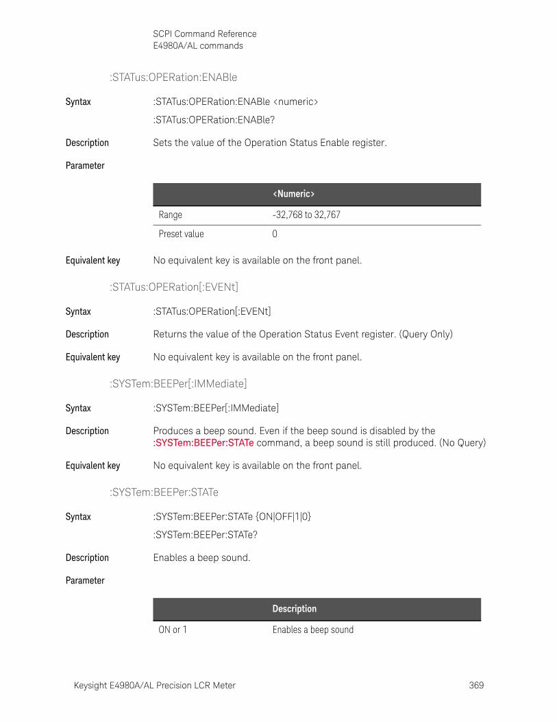
Keysight E4980A/AL Precision LCR Meter 369
SCPI Command ReferenceE4980A/AL commands
:STATus:OPERation:ENABle
Syntax :STATus:OPERation:ENABle <numeric>
:STATus:OPERation:ENABle?
Description Sets the value of the Operation Status Enable register.
Parameter
Equivalent key No equivalent key is available on the front panel.
:STATus:OPERation[:EVENt]
Syntax :STATus:OPERation[:EVENt]
Description Returns the value of the Operation Status Event register. (Query Only)
Equivalent key No equivalent key is available on the front panel.
:SYSTem:BEEPer[:IMMediate]
Syntax :SYSTem:BEEPer[:IMMediate]
Description Produces a beep sound. Even if the beep sound is disabled by the :SYSTem:BEEPer:STATe command, a beep sound is still produced. (No Query)
Equivalent key No equivalent key is available on the front panel.
:SYSTem:BEEPer:STATe
Syntax :SYSTem:BEEPer:STATe {ON|OFF|1|0}
:SYSTem:BEEPer:STATe?
Description Enables a beep sound.
Parameter
<Numeric>
Range -32,768 to 32,767
Preset value 0
Description
ON or 1 Enables a beep sound

370 Keysight E4980A/AL Precision LCR Meter
SCPI Command ReferenceE4980A/AL commands
10-
Equivalent key [System] - SYSTEM CONFIG - BEEPER ENABLED - ON
[System] - SYSTEM CONFIG - BEEPER ENABLED - OFF
:SYSTem:BEEPer:TONE
Syntax :SYSTem:BEEPer:TONE <numeric>
:SYSTem:BEEPer:TONE?
Description Selects a beep sound tone.
Parameter
Equivalent key [System] - SYSTEM CONFIG - BEEPER TONE - TONE 1
[System] - SYSTEM CONFIG - BEEPER TONE - TONE 2
[System] - SYSTEM CONFIG - BEEPER TONE - TONE 3
[System] - SYSTEM CONFIG - BEEPER TONE - TONE 4
[System] - SYSTEM CONFIG - BEEPER TONE - TONE 5
:SYSTem:COMMunicate:GPIB[:SELF]:ADDRess
Syntax :SYSTem:COMMunicate:GPIB[:SELF]:ADDRess <numeric>
:SYSTem:COMMunicate:GPIB[:SELF]:ADDRess?
Description Sets the GPIB address.
Parameter
OFF or 0 (Preset value) Disables a beep sound
Description
<Numeric>
Range 1 to 5
Preset value 3
Resolution 1
<Numeric>
Range 0 to 30
Preset value 17
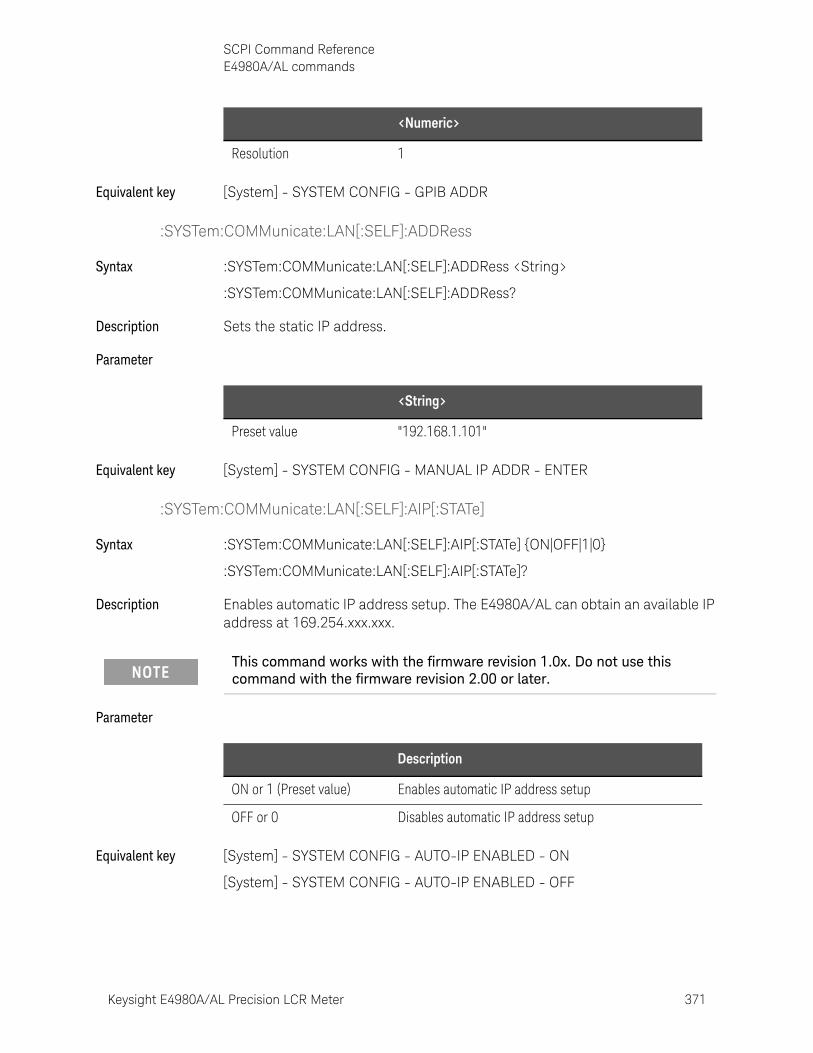
Keysight E4980A/AL Precision LCR Meter 371
SCPI Command ReferenceE4980A/AL commands
Equivalent key [System] - SYSTEM CONFIG - GPIB ADDR
:SYSTem:COMMunicate:LAN[:SELF]:ADDRess
Syntax :SYSTem:COMMunicate:LAN[:SELF]:ADDRess <String>
:SYSTem:COMMunicate:LAN[:SELF]:ADDRess?
Description Sets the static IP address.
Parameter
Equivalent key [System] - SYSTEM CONFIG - MANUAL IP ADDR - ENTER
:SYSTem:COMMunicate:LAN[:SELF]:AIP[:STATe]
Syntax :SYSTem:COMMunicate:LAN[:SELF]:AIP[:STATe] {ON|OFF|1|0}
:SYSTem:COMMunicate:LAN[:SELF]:AIP[:STATe]?
Description Enables automatic IP address setup. The E4980A/AL can obtain an available IP address at 169.254.xxx.xxx.
Parameter
Equivalent key [System] - SYSTEM CONFIG - AUTO-IP ENABLED - ON
[System] - SYSTEM CONFIG - AUTO-IP ENABLED - OFF
Resolution 1
<Numeric>
<String>
Preset value "192.168.1.101"
This command works with the firmware revision 1.0x. Do not use this command with the firmware revision 2.00 or later.
Description
ON or 1 (Preset value) Enables automatic IP address setup
OFF or 0 Disables automatic IP address setup
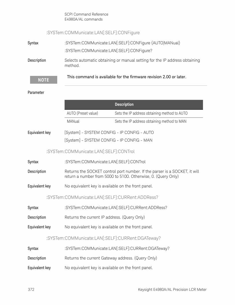
372 Keysight E4980A/AL Precision LCR Meter
SCPI Command ReferenceE4980A/AL commands
10-
:SYSTem:COMMunicate:LAN[:SELF]:CONFigure
Syntax :SYSTem:COMMunicate:LAN[:SELF]:CONFigure {AUTO|MANual}
:SYSTem:COMMunicate:LAN[:SELF]:CONFigure?
Description Selects automatic obtaining or manual setting for the IP address obtaining method.
Parameter
Equivalent key [System] - SYSTEM CONFIG - IP CONFIG - AUTO
[System] - SYSTEM CONFIG - IP CONFIG - MAN
:SYSTem:COMMunicate:LAN[:SELF]:CONTrol
Syntax :SYSTem:COMMunicate:LAN[:SELF]:CONTrol
Description Returns the SOCKET control port number. If the parser is a SOCKET, it will return a number from 5000 to 5100. Otherwise, 0. (Query Only)
Equivalent key No equivalent key is available on the front panel.
:SYSTem:COMMunicate:LAN[:SELF]:CURRent:ADDRess?
Syntax :SYSTem:COMMunicate:LAN[:SELF]:CURRent:ADDRess?
Description Returns the current IP address. (Query Only)
Equivalent key No equivalent key is available on the front panel.
:SYSTem:COMMunicate:LAN[:SELF]:CURRent:DGATeway?
Syntax :SYSTem:COMMunicate:LAN[:SELF]:CURRent:DGATeway?
Description Returns the current Gateway address. (Query Only)
Equivalent key No equivalent key is available on the front panel.
This command is available for the firmware revision 2.00 or later.
Description
AUTO (Preset value) Sets the IP address obtaining method to AUTO
MANual Sets the IP address obtaining method to MAN
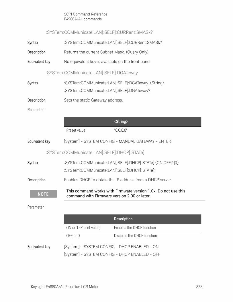
Keysight E4980A/AL Precision LCR Meter 373
SCPI Command ReferenceE4980A/AL commands
:SYSTem:COMMunicate:LAN[:SELF]:CURRent:SMASk?
Syntax :SYSTem:COMMunicate:LAN[:SELF]:CURRent:SMASk?
Description Returns the current Subnet Mask. (Query Only)
Equivalent key No equivalent key is available on the front panel.
:SYSTem:COMMunicate:LAN[:SELF]:DGATeway
Syntax :SYSTem:COMMunicate:LAN[:SELF]:DGATeway <String>
:SYSTem:COMMunicate:LAN[:SELF]:DGATeway?
Description Sets the static Gateway address.
Parameter
Equivalent key [System] - SYSTEM CONFIG - MANUAL GATEWAY - ENTER
:SYSTem:COMMunicate:LAN[:SELF]:DHCP[:STATe]
Syntax :SYSTem:COMMunicate:LAN[:SELF]:DHCP[:STATe] {ON|OFF|1|0}
:SYSTem:COMMunicate:LAN[:SELF]:DHCP[:STATe]?
Description Enables DHCP to obtain the IP address from a DHCP server.
Parameter
Equivalent key [System] - SYSTEM CONFIG - DHCP ENABLED - ON
[System] - SYSTEM CONFIG - DHCP ENABLED - OFF
<String>
Preset value "0.0.0.0"
This command works with Firmware version 1.0x. Do not use this command with Firmware version 2.00 or later.
Description
ON or 1 (Preset value) Enables the DHCP function
OFF or 0 Disables the DHCP function
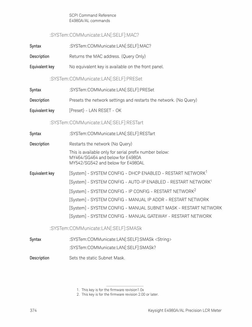
374 Keysight E4980A/AL Precision LCR Meter
SCPI Command ReferenceE4980A/AL commands
10-
:SYSTem:COMMunicate:LAN[:SELF]:MAC?
Syntax :SYSTem:COMMunicate:LAN[:SELF]:MAC?
Description Returns the MAC address. (Query Only)
Equivalent key No equivalent key is available on the front panel.
:SYSTem:COMMunicate:LAN[:SELF]:PRESet
Syntax :SYSTem:COMMunicate:LAN[:SELF]:PRESet
Description Presets the network settings and restarts the network. (No Query)
Equivalent key [Preset} - LAN RESET - OK
:SYSTem:COMMunicate:LAN[:SELF]:RESTart
Syntax :SYSTem:COMMunicate:LAN[:SELF]:RESTart
Description Restarts the network (No Query)
This is available only for serial prefix number below: MY464/SG464 and below for E4980A MY542/SG542 and below for E4980AL
Equivalent key [System] - SYSTEM CONFIG - DHCP ENABLED - RESTART NETWORK1
[System] - SYSTEM CONFIG - AUTO-IP ENABLED - RESTART NETWORK1
[System] - SYSTEM CONFIG - IP CONFIG - RESTART NETWORK2
[System] - SYSTEM CONFIG - MANUAL IP ADDR - RESTART NETWORK
[System] - SYSTEM CONFIG - MANUAL SUBNET MASK - RESTART NETWORK
[System] - SYSTEM CONFIG - MANUAL GATEWAY - RESTART NETWORK
:SYSTem:COMMunicate:LAN[:SELF]:SMASk
Syntax :SYSTem:COMMunicate:LAN[:SELF]:SMASk <String>
:SYSTem:COMMunicate:LAN[:SELF]:SMASk?
Description Sets the static Subnet Mask.
1. This key is for the firmware revision1.0x2. This key is for the firmware revision 2.00 or later.
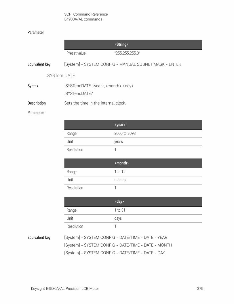
Keysight E4980A/AL Precision LCR Meter 375
SCPI Command ReferenceE4980A/AL commands
Parameter
Equivalent key [System] - SYSTEM CONFIG - MANUAL SUBNET MASK - ENTER
:SYSTem:DATE
Syntax :SYSTem:DATE <year>,<month>,<day>
:SYSTem:DATE?
Description Sets the time in the internal clock.
Parameter
Equivalent key [System] - SYSTEM CONFIG - DATE/TIME - DATE - YEAR
[System] - SYSTEM CONFIG - DATE/TIME - DATE - MONTH
[System] - SYSTEM CONFIG - DATE/TIME - DATE - DAY
<String>
Preset value "255.255.255.0"
<year>
Range 2000 to 2098
Unit years
Resolution 1
<month>
Range 1 to 12
Unit months
Resolution 1
<day>
Range 1 to 31
Unit days
Resolution 1

376 Keysight E4980A/AL Precision LCR Meter
SCPI Command ReferenceE4980A/AL commands
10-
:SYSTem:ERRor[:NEXT]?
Syntax :SYSTem:ERRor[:NEXT]?
Description Returns an error message. (Query Only)
Equivalent key No equivalent key is available on the front panel.
:SYSTem:KLOCk
Syntax :SYSTem:KLOCk {ON|OFF|1|0}
:SYSTem:KLOCk?
Description Enables the front panel key lock. If the key lock’s pin on the handle interface is set to “LOCK,” touching the keys will have no effect.
Parameter
Equivalent key [Local/Lock]
:SYSTem:PERSona:MANufacturer[:NAME]
Syntax :SYSTem:PERSona:MANufacturer[:NAME] <string>
Description This command only accepts two non-case sensitive strings “Agilent Technologies” and “Keysight Technologies”. A power cycle or reboot is required for the changes in the instrument’s manufacturer string to take effect and to be recognized in the Keysight Connection Expert. The string will remain for the subsequent power cycle or reboot.
Equivalent key No equivalent key is available on the front panel.
:SYSTem:PERSona:MANufacturer:DEFault
Syntax :SYSTem:PERSona:MANufacturer:DEFault
Description This command sets the instrument’s manufacturer to “Keysight Technologies” which is the default manufacturer setting.
Equivalent key No equivalent key is available on the front panel.
Description
ON or 1 Enables the Front panel key lock
OFF or 0 (Preset value) Disables the Front panel key lock
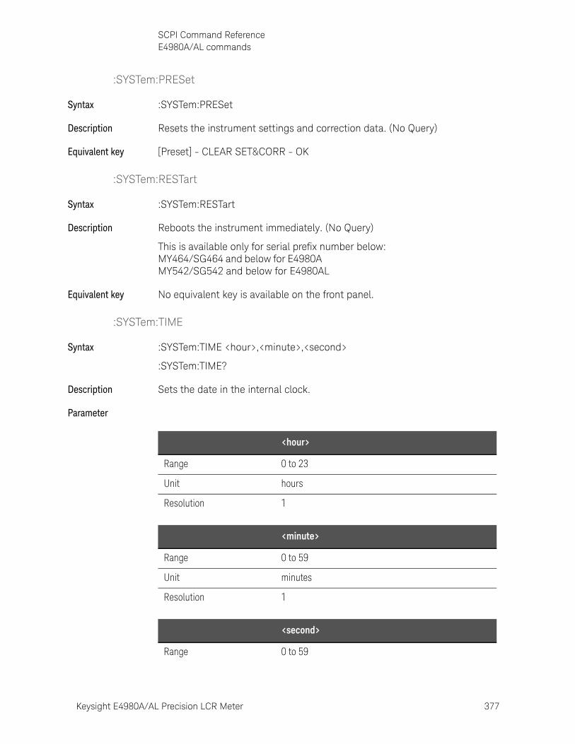
Keysight E4980A/AL Precision LCR Meter 377
SCPI Command ReferenceE4980A/AL commands
:SYSTem:PRESet
Syntax :SYSTem:PRESet
Description Resets the instrument settings and correction data. (No Query)
Equivalent key [Preset] - CLEAR SET&CORR - OK
:SYSTem:RESTart
Syntax :SYSTem:RESTart
Description Reboots the instrument immediately. (No Query)
This is available only for serial prefix number below: MY464/SG464 and below for E4980A MY542/SG542 and below for E4980AL
Equivalent key No equivalent key is available on the front panel.
:SYSTem:TIME
Syntax :SYSTem:TIME <hour>,<minute>,<second>
:SYSTem:TIME?
Description Sets the date in the internal clock.
Parameter
<hour>
Range 0 to 23
Unit hours
Resolution 1
<minute>
Range 0 to 59
Unit minutes
Resolution 1
<second>
Range 0 to 59
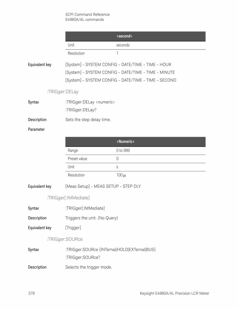
378 Keysight E4980A/AL Precision LCR Meter
SCPI Command ReferenceE4980A/AL commands
10-
Equivalent key [System] - SYSTEM CONFIG - DATE/TIME - TIME - HOUR
[System] - SYSTEM CONFIG - DATE/TIME - TIME - MINUTE
[System] - SYSTEM CONFIG - DATE/TIME - TIME - SECOND
:TRIGger:DELay
Syntax :TRIGger:DELay <numeric>
:TRIGger:DELay?
Description Sets the step delay time.
Parameter
Equivalent key [Meas Setup] - MEAS SETUP - STEP DLY
:TRIGger[:IMMediate]
Syntax :TRIGger[:IMMediate]
Description Triggers the unit. (No Query)
Equivalent key [Trigger]
:TRIGger:SOURce
Syntax :TRIGger:SOURce {INTernal|HOLD|EXTernal|BUS}
:TRIGger:SOURce?
Description Selects the trigger mode.
Unit seconds
Resolution 1
<second>
<Numeric>
Range 0 to 999
Preset value 0
Unit s
Resolution 100
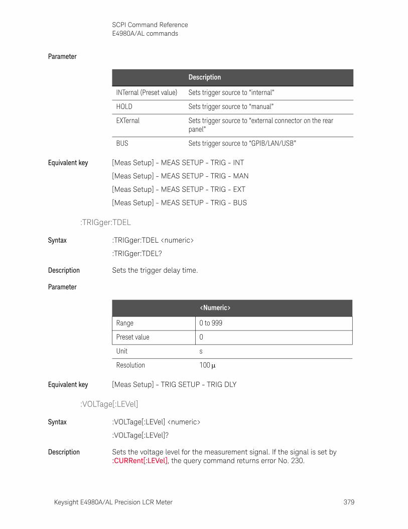
Keysight E4980A/AL Precision LCR Meter 379
SCPI Command ReferenceE4980A/AL commands
Parameter
Equivalent key [Meas Setup] - MEAS SETUP - TRIG - INT
[Meas Setup] - MEAS SETUP - TRIG - MAN
[Meas Setup] - MEAS SETUP - TRIG - EXT
[Meas Setup] - MEAS SETUP - TRIG - BUS
:TRIGger:TDEL
Syntax :TRIGger:TDEL <numeric>
:TRIGger:TDEL?
Description Sets the trigger delay time.
Parameter
Equivalent key [Meas Setup] - TRIG SETUP - TRIG DLY
:VOLTage[:LEVel]
Syntax :VOLTage[:LEVel] <numeric>
:VOLTage[:LEVel]?
Description Sets the voltage level for the measurement signal. If the signal is set by :CURRent[:LEVel], the query command returns error No. 230.
Description
INTernal (Preset value) Sets trigger source to “internal”
HOLD Sets trigger source to “manual”
EXTernal Sets trigger source to “external connector on the rear panel”
BUS Sets trigger source to “GPIB/LAN/USB”
<Numeric>
Range 0 to 999
Preset value 0
Unit s
Resolution 100
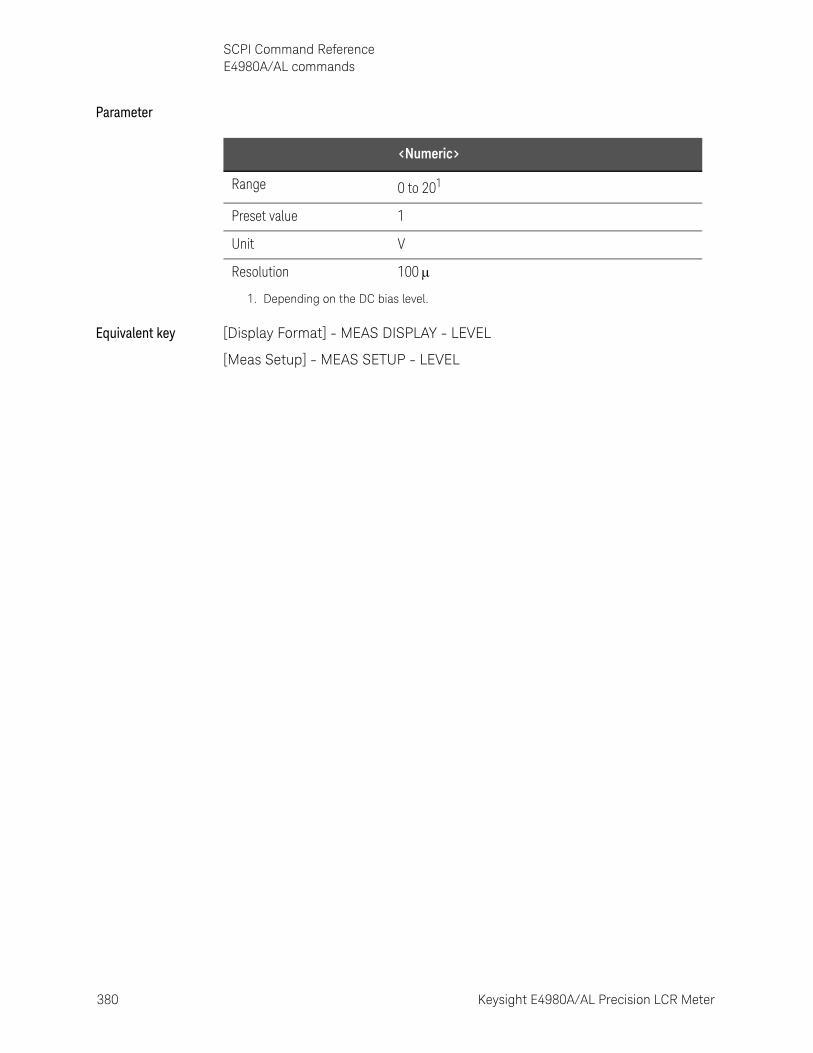
380 Keysight E4980A/AL Precision LCR Meter
SCPI Command ReferenceE4980A/AL commands
10-
Parameter
Equivalent key [Display Format] - MEAS DISPLAY - LEVEL
[Meas Setup] - MEAS SETUP - LEVEL
<Numeric>
Range 0 to 201
Preset value 1
Unit V
Resolution 100
1. Depending on the DC bias level.
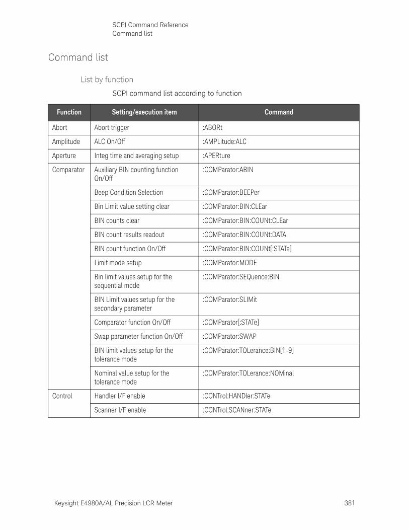
Keysight E4980A/AL Precision LCR Meter 381
SCPI Command ReferenceCommand list
Command list
List by function
SCPI command list according to function
Function Setting/execution item Command
Abort Abort trigger :ABORt
Amplitude ALC On/Off :AMPLitude:ALC
Aperture Integ time and averaging setup :APERture
Comparator Auxiliary BIN counting function On/Off
:COMParator:ABIN
Beep Condition Selection :COMParator:BEEPer
Bin Limit value setting clear :COMParator:BIN:CLEar
BIN counts clear :COMParator:BIN:COUNt:CLEar
BIN count results readout :COMParator:BIN:COUNt:DATA
BIN count function On/Off :COMParator:BIN:COUNt[:STATe]
Limit mode setup :COMParator:MODE
Bin limit values setup for the sequential mode
:COMParator:SEQuence:BIN
BIN Limit values setup for the secondary parameter
:COMParator:SLIMit
Comparator function On/Off :COMParator[:STATe]
Swap parameter function On/Off :COMParator:SWAP
BIN limit values setup for the tolerance mode
:COMParator:TOLerance:BIN[1-9]
Nominal value setup for the tolerance mode
:COMParator:TOLerance:NOMinal
Control Handler I/F enable :CONTrol:HANDler:STATe
Scanner I/F enable :CONTrol:SCANner:STATe
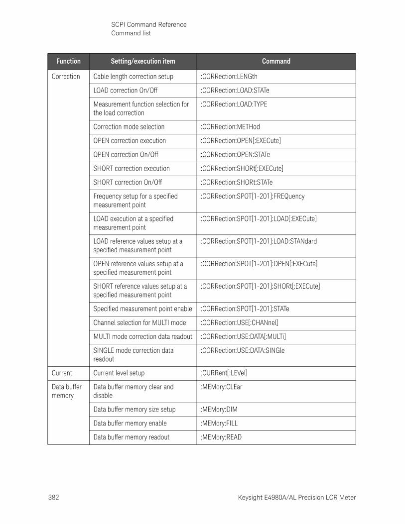
382 Keysight E4980A/AL Precision LCR Meter
SCPI Command ReferenceCommand list
10-
Correction Cable length correction setup :CORRection:LENGth
LOAD correction On/Off :CORRection:LOAD:STATe
Measurement function selection for the load correction
:CORRection:LOAD:TYPE
Correction mode selection :CORRection:METHod
OPEN correction execution :CORRection:OPEN[:EXECute]
OPEN correction On/Off :CORRection:OPEN:STATe
SHORT correction execution :CORRection:SHORt[:EXECute]
SHORT correction On/Off :CORRection:SHORt:STATe
Frequency setup for a specified measurement point
:CORRection:SPOT[1-201]:FREQuency
LOAD execution at a specified measurement point
:CORRection:SPOT[1-201]:LOAD[:EXECute]
LOAD reference values setup at a specified measurement point
:CORRection:SPOT[1-201]:LOAD:STANdard
OPEN reference values setup at a specified measurement point
:CORRection:SPOT[1-201]:OPEN[:EXECute]
SHORT reference values setup at a specified measurement point
:CORRection:SPOT[1-201]:SHORt[:EXECute]
Specified measurement point enable :CORRection:SPOT[1-201]:STATe
Channel selection for MULTI mode :CORRection:USE[:CHANnel]
MULTI mode correction data readout :CORRection:USE:DATA[:MULTi]
SINGLE mode correction data readout
:CORRection:USE:DATA:SINGle
Current Current level setup :CURRent[:LEVel]
Data buffer memory
Data buffer memory clear and disable
:MEMory:CLEar
Data buffer memory size setup :MEMory:DIM
Data buffer memory enable :MEMory:FILL
Data buffer memory readout :MEMory:READ
Function Setting/execution item Command
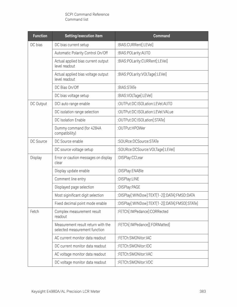
Keysight E4980A/AL Precision LCR Meter 383
SCPI Command ReferenceCommand list
DC bias DC bias current setup :BIAS:CURRent[:LEVel]
Automatic Polarity Control On/Off :BIAS:POLarity:AUTO
Actual applied bias current output level readout
:BIAS:POLarity:CURRent[:LEVel]
Actual applied bias voltage output level readout
:BIAS:POLarity:VOLTage[:LEVel]
DC Bias On/Off :BIAS:STATe
DC bias voltage setup :BIAS:VOLTage[:LEVel]
DC Output DCI auto range enable :OUTPut:DC:ISOLation:LEVel:AUTO
DC isolation range selection :OUTPut:DC:ISOLation:LEVel:VALue
DC Isolation Enable :OUTPut:DC:ISOLation[:STATe]
Dummy command (for 4284A compatibility)
:OUTPut:HPOWer
DC Source DC Source enable :SOURce:DCSource:STATe
DC source voltage setup :SOURce:DCSource:VOLTage[:LEVel]
Display Error or caution messages on display clear
:DISPlay:CCLear
Display update enable :DISPlay:ENABle
Comment line entry :DISPlay:LINE
Displayed page selection :DISPlay:PAGE
Most siginificant digit selection :DISPlay[:WINDow]:TEXT[1-2][:DATA]:FMSD:DATA
Fixed decimal point mode enable :DISPlay[:WINDow]:TEXT[1-2][:DATA]:FMSD[:STATe]
Fetch Complex measurement result readout
:FETCh[:IMPedance]:CORRected
Measurement result return with the selected measurement function
:FETCh[:IMPedance][:FORMatted]
AC current monitor data readout :FETCh:SMONitor:IAC
DC current monitor data readout :FETCh:SMONitor:IDC
AC voltage monitor data readout :FETCh:SMONitor:VAC
DC voltage monitor data readout :FETCh:SMONitor:VDC
Function Setting/execution item Command
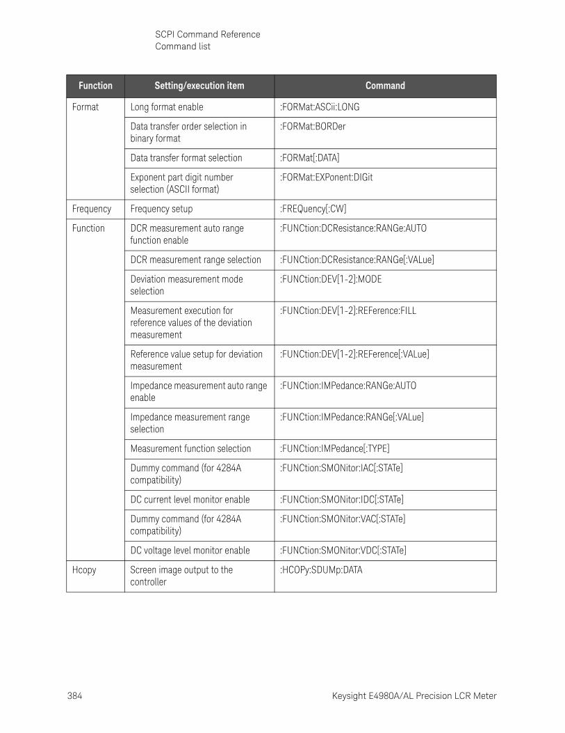
384 Keysight E4980A/AL Precision LCR Meter
SCPI Command ReferenceCommand list
10-
Format Long format enable :FORMat:ASCii:LONG
Data transfer order selection in binary format
:FORMat:BORDer
Data transfer format selection :FORMat[:DATA]
Exponent part digit number selection (ASCII format)
:FORMat:EXPonent:DIGit
Frequency Frequency setup :FREQuency[:CW]
Function DCR measurement auto range function enable
:FUNCtion:DCResistance:RANGe:AUTO
DCR measurement range selection :FUNCtion:DCResistance:RANGe[:VALue]
Deviation measurement mode selection
:FUNCtion:DEV[1-2]:MODE
Measurement execution for reference values of the deviation measurement
:FUNCtion:DEV[1-2]:REFerence:FILL
Reference value setup for deviation measurement
:FUNCtion:DEV[1-2]:REFerence[:VALue]
Impedance measurement auto range enable
:FUNCtion:IMPedance:RANGe:AUTO
Impedance measurement range selection
:FUNCtion:IMPedance:RANGe[:VALue]
Measurement function selection :FUNCtion:IMPedance[:TYPE]
Dummy command (for 4284A compatibility)
:FUNCtion:SMONitor:IAC[:STATe]
DC current level monitor enable :FUNCtion:SMONitor:IDC[:STATe]
Dummy command (for 4284A compatibility)
:FUNCtion:SMONitor:VAC[:STATe]
DC voltage level monitor enable :FUNCtion:SMONitor:VDC[:STATe]
Hcopy Screen image output to the controller
:HCOPy:SDUMp:DATA
Function Setting/execution item Command
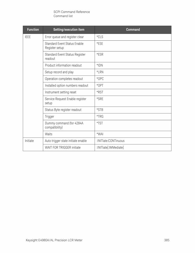
Keysight E4980A/AL Precision LCR Meter 385
SCPI Command ReferenceCommand list
IEEE Error queue and register clear *CLS
Standard Event Status Enable Register setup
*ESE
Standard Event Status Register readout
*ESR
Product information readout *IDN
Setup record and play *LRN
Operation completes readout *OPC
Installed option numbers readout *OPT
Instrument setting reset *RST
Service Request Enable register setup
*SRE
Status Byte register readout *STB
Trigger *TRG
Dummy command (for 4284A compatibility)
*TST
Waits *WAI
Initiate Auto trigger state initiate enable :INITiate:CONTinuous
WAIT FOR TRIGGER initiate :INITiate[:IMMediate]
Function Setting/execution item Command

386 Keysight E4980A/AL Precision LCR Meter
SCPI Command ReferenceCommand list
10-
List Sweep Limit value setup for the list sweep measurement.
:LIST:BAND[1-201]
DC current list sweep setup :LIST:BIAS:CURRent
DC voltage list sweep setup :LIST:BIAS:VOLTage
List sweep setup clear :LIST:CLEar:ALL
AC current list sweep setup :LIST:CURRent
DC source list sweep setup :LIST:DCSource:VOLTage
Frequecy list sweep setup :LIST:FREQuency
Sweep mode selection for list sweep :LIST:MODE
Time stamp clear of the executed list sweep
:LIST:SEQuence:TSTamp:CLEar
Time stamp readout of the list sweep :LIST:SEQuence:TSTamp:DATA
List sweep setup parameter :LIST:STIMulus:DATA
Actual stimulus values readout for list sweep parameter
:LIST:STIMulus:MDATa
Parameter types selection for list sweep parameter
:LIST:STIMulus:TYPE
AC voltage list sweep setup :LIST:VOLTage
Save/Recall State delete from the memories :MMEMory:DELete[:REGister]
State Load from the memories :MMEMory:LOAD:STATe[:REGister]
State Store to the memories :MMEMory:STORe:STATe[:REGister]
Status register
Operation Status Condition register readout
:STATus:OPERation:CONDition
Operation Status Enable register setup
:STATus:OPERation:ENABle
Operation Status Event register return
:STATus:OPERation[:EVENt]
Function Setting/execution item Command

Keysight E4980A/AL Precision LCR Meter 387
SCPI Command ReferenceCommand list
System Beeps :SYSTem:BEEPer[:IMMediate]
Beep sound enable :SYSTem:BEEPer:STATe
Beep sound tone selection :SYSTem:BEEPer:TONE
GPIB address setup :SYSTem:COMMunicate:GPIB[:SELF]:ADDRess
Static IP address setup :SYSTem:COMMunicate:LAN[:SELF]:ADDRess
IP address obtaining method :SYSTem:COMMunicate:LAN[:SELF]:CONFigure
SOCKET control port number readout
:SYSTem:COMMunicate:LAN[:SELF]:CONTrol
Current IP address readout :SYSTem:COMMunicate:LAN[:SELF]:CURRent:ADDRess
Current Gateway address readout :SYSTem:COMMunicate:LAN[:SELF]:CURRent:DGATeway
Current Subnet Mask readout :SYSTem:COMMunicate:LAN[:SELF]:CURRent:SMASk
Static Gateway address setup :SYSTem:COMMunicate:LAN[:SELF]:DGATeway
MAC address readout :SYSTem:COMMunicate:LAN[:SELF]:MAC
Network preset :SYSTem:COMMunicate:LAN[:SELF]:PRESet
Static Subnet Mask setup :SYSTem:COMMunicate:LAN[:SELF]:SMASk
Clock time setup :SYSTem:DATE
Error message readout :SYSTem:ERRor[:NEXT]
Front panel key lock enable :SYSTem:KLOCk
Instrument setting and correction data reset
:SYSTem:PRESet
Clock date setup :SYSTem:TIME
Trigger Step delay time setup :TRIGger:DELay
Trigger :TRIGger[:IMMediate]
Selects the trigger mode :TRIGger:SOURce
Trigger delay time setup :TRIGger:TDEL
Voltage Voltage level setup :VOLTage[:LEVel]
Function Setting/execution item Command
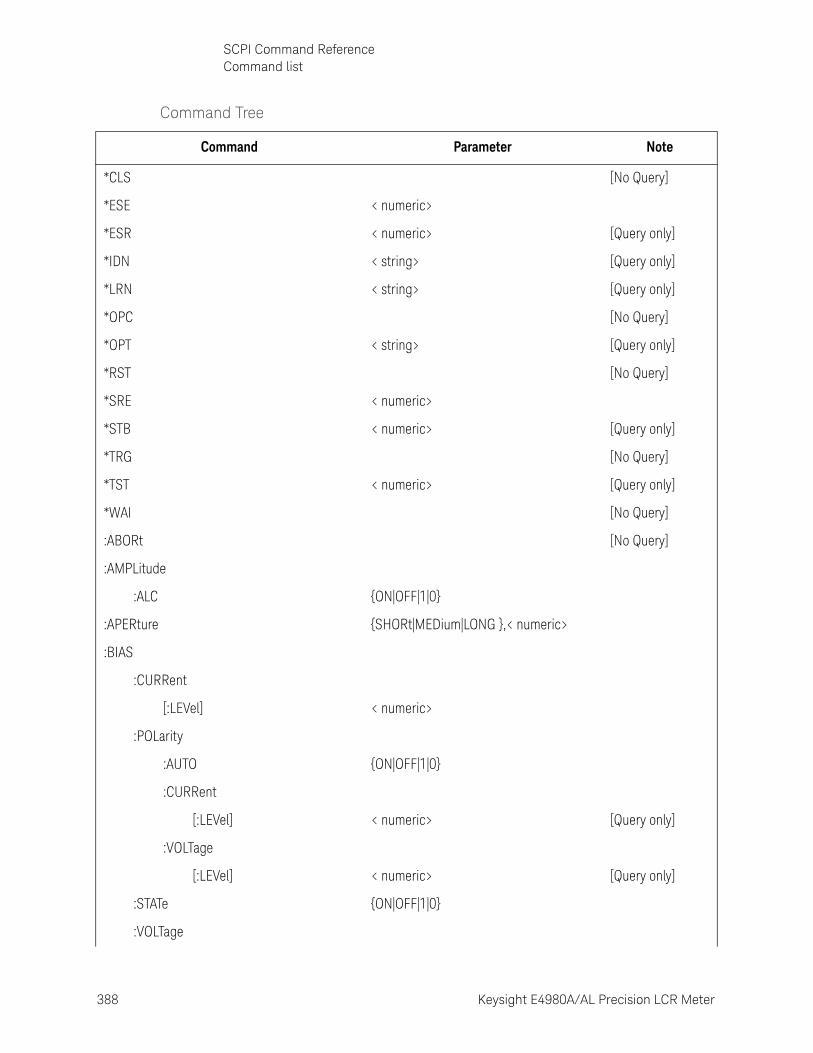
388 Keysight E4980A/AL Precision LCR Meter
SCPI Command ReferenceCommand list
10-
Command Tree
Command Parameter Note
*CLS [No Query]
*ESE < numeric>
*ESR < numeric> [Query only]
*IDN < string> [Query only]
*LRN < string> [Query only]
*OPC [No Query]
*OPT < string> [Query only]
*RST [No Query]
*SRE < numeric>
*STB < numeric> [Query only]
*TRG [No Query]
*TST < numeric> [Query only]
*WAI [No Query]
:ABORt [No Query]
:AMPLitude
:ALC {ON|OFF|1|0}
:APERture {SHORt|MEDium|LONG },< numeric>
:BIAS
:CURRent
[:LEVel] < numeric>
:POLarity
:AUTO {ON|OFF|1|0}
:CURRent
[:LEVel] < numeric> [Query only]
:VOLTage
[:LEVel] < numeric> [Query only]
:STATe {ON|OFF|1|0}
:VOLTage
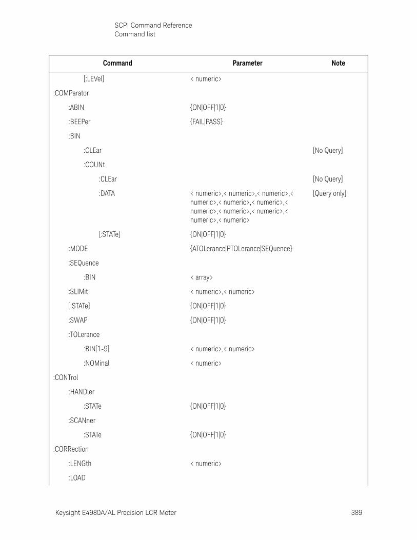
Keysight E4980A/AL Precision LCR Meter 389
SCPI Command ReferenceCommand list
[:LEVel] < numeric>
:COMParator
:ABIN {ON|OFF|1|0}
:BEEPer {FAIL|PASS}
:BIN
:CLEar [No Query]
:COUNt
:CLEar [No Query]
:DATA < numeric>,< numeric>,< numeric>,< numeric>,< numeric>,< numeric>,< numeric>,< numeric>,< numeric>,< numeric>,< numeric>
[Query only]
[:STATe] {ON|OFF|1|0}
:MODE {ATOLerance|PTOLerance|SEQuence}
:SEQuence
:BIN < array>
:SLIMit < numeric>,< numeric>
[:STATe] {ON|OFF|1|0}
:SWAP {ON|OFF|1|0}
:TOLerance
:BIN[1-9] < numeric>,< numeric>
:NOMinal < numeric>
:CONTrol
:HANDler
:STATe {ON|OFF|1|0}
:SCANner
:STATe {ON|OFF|1|0}
:CORRection
:LENGth < numeric>
:LOAD
Command Parameter Note
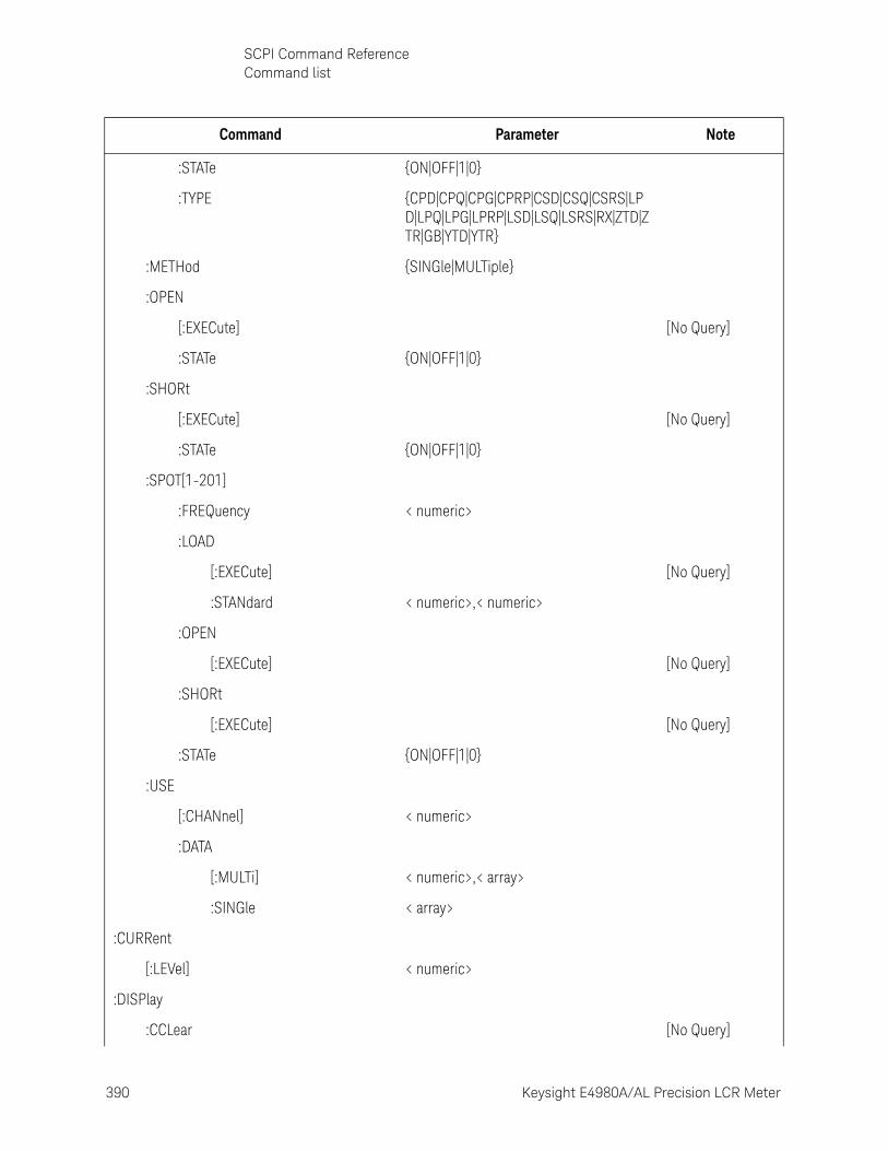
390 Keysight E4980A/AL Precision LCR Meter
SCPI Command ReferenceCommand list
10-
:STATe {ON|OFF|1|0}
:TYPE {CPD|CPQ|CPG|CPRP|CSD|CSQ|CSRS|LPD|LPQ|LPG|LPRP|LSD|LSQ|LSRS|RX|ZTD|ZTR|GB|YTD|YTR}
:METHod {SINGle|MULTiple}
:OPEN
[:EXECute] [No Query]
:STATe {ON|OFF|1|0}
:SHORt
[:EXECute] [No Query]
:STATe {ON|OFF|1|0}
:SPOT[1-201]
:FREQuency < numeric>
:LOAD
[:EXECute] [No Query]
:STANdard < numeric>,< numeric>
:OPEN
[:EXECute] [No Query]
:SHORt
[:EXECute] [No Query]
:STATe {ON|OFF|1|0}
:USE
[:CHANnel] < numeric>
:DATA
[:MULTi] < numeric>,< array>
:SINGle < array>
:CURRent
[:LEVel] < numeric>
:DISPlay
:CCLear [No Query]
Command Parameter Note
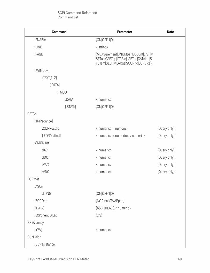
Keysight E4980A/AL Precision LCR Meter 391
SCPI Command ReferenceCommand list
:ENABle {ON|OFF|1|0}
:LINE < string>
:PAGE {MEASurement|BNUMber|BCOunt|LIST|MSETup|CSETup|LTABle|LSETup|CATAlog|SYSTem|SELF|MLARge|SCONfig|SERVice}
[:WINDow]
:TEXT[1-2]
[:DATA]
:FMSD
:DATA < numeric>
[:STATe] {ON|OFF|1|0}
:FETCh
[:IMPedance]
:CORRected < numeric>,< numeric> [Query only]
[:FORMatted] < numeric>,< numeric>,< numeric> [Query only]
:SMONitor
:IAC < numeric> [Query only]
:IDC < numeric> [Query only]
:VAC < numeric> [Query only]
:VDC < numeric> [Query only]
:FORMat
:ASCii
:LONG {ON|OFF|1|0}
:BORDer {NORMal|SWAPped}
[:DATA] {ASCii|REAL },< numeric>
:EXPonent:DIGit {2|3}
:FREQuency
[:CW] < numeric>
:FUNCtion
:DCResistance
Command Parameter Note
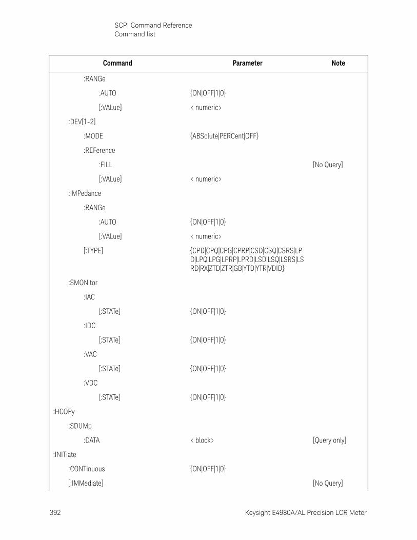
392 Keysight E4980A/AL Precision LCR Meter
SCPI Command ReferenceCommand list
10-
:RANGe
:AUTO {ON|OFF|1|0}
[:VALue] < numeric>
:DEV[1-2]
:MODE {ABSolute|PERCent|OFF}
:REFerence
:FILL [No Query]
[:VALue] < numeric>
:IMPedance
:RANGe
:AUTO {ON|OFF|1|0}
[:VALue] < numeric>
[:TYPE] {CPD|CPQ|CPG|CPRP|CSD|CSQ|CSRS|LPD|LPQ|LPG|LPRP|LPRD|LSD|LSQ|LSRS|LSRD|RX|ZTD|ZTR|GB|YTD|YTR|VDID}
:SMONitor
:IAC
[:STATe] {ON|OFF|1|0}
:IDC
[:STATe] {ON|OFF|1|0}
:VAC
[:STATe] {ON|OFF|1|0}
:VDC
[:STATe] {ON|OFF|1|0}
:HCOPy
:SDUMp
:DATA < block> [Query only]
:INITiate
:CONTinuous {ON|OFF|1|0}
[:IMMediate] [No Query]
Command Parameter Note
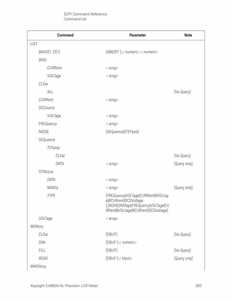
Keysight E4980A/AL Precision LCR Meter 393
SCPI Command ReferenceCommand list
:LIST
:BAND[1-201] {A|B|OFF },< numeric>,< numeric>
:BIAS
:CURRent < array>
:VOLTage < array>
:CLEar
:ALL [No Query]
:CURRent < array>
:DCSource
:VOLTage < array>
:FREQuency < array>
:MODE {SEQuence|STEPped}
:SEQuence
:TSTamp
:CLEar [No Query]
:DATA < array> [Query only]
:STIMulus
:DATA < array>
:MDATa < array> [Query only]
:TYPE {FREQuency|VOLTage|CURRent|BVOLtage|BCURrent|DCSVoltage },{NONE|IRANge|FREQuency|VOLTage|CURRent|BVOLtage|BCURrent|DCSVoltage}
:VOLTage < array>
:MEMory
:CLEar {DBUF} [No Query]
:DIM {DBUF },< numeric>
:FILL {DBUF} [No Query]
:READ {DBUF },< block> [Query only]
:MMEMory
Command Parameter Note
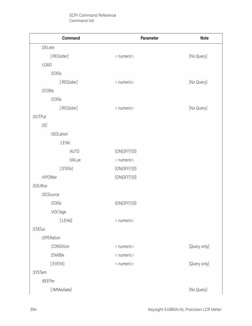
394 Keysight E4980A/AL Precision LCR Meter
SCPI Command ReferenceCommand list
10-
:DELete
[:REGister] < numeric> [No Query]
:LOAD
:STATe
[:REGister] < numeric> [No Query]
:STORe
:STATe
[:REGister] < numeric> [No Query]
:OUTPut
:DC
:ISOLation
:LEVel
:AUTO {ON|OFF|1|0}
:VALue < numeric>
[:STATe] {ON|OFF|1|0}
:HPOWer {ON|OFF|1|0}
:SOURce
:DCSource
:STATe {ON|OFF|1|0}
:VOLTage
[:LEVel] < numeric>
:STATus
:OPERation
:CONDition < numeric> [Query only]
:ENABle < numeric>
[:EVENt] < numeric> [Query only]
:SYSTem
:BEEPer
[:IMMediate] [No Query]
Command Parameter Note
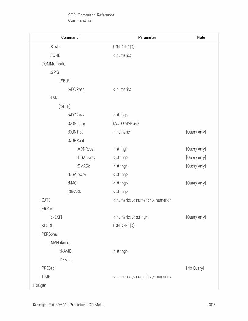
Keysight E4980A/AL Precision LCR Meter 395
SCPI Command ReferenceCommand list
:STATe {ON|OFF|1|0}
:TONE < numeric>
:COMMunicate
:GPIB
[:SELF]
:ADDRess < numeric>
:LAN
[:SELF]
:ADDRess < string>
:CONFigre {AUTO|MANual}
:CONTrol < numeric> [Query only]
:CURRent
:ADDRess < string> [Query only]
:DGATeway < string> [Query only]
:SMASk < string> [Query only]
:DGATeway < string>
:MAC < string> [Query only]
:SMASk < string>
:DATE < numeric>,< numeric>,< numeric>
:ERRor
[:NEXT] < numeric>,< string> [Query only]
:KLOCk {ON|OFF|1|0}
:PERSona
:MANufacture
[:NAME] < string>
:DEFault
:PRESet [No Query]
:TIME < numeric>,< numeric>,< numeric>
:TRIGger
Command Parameter Note
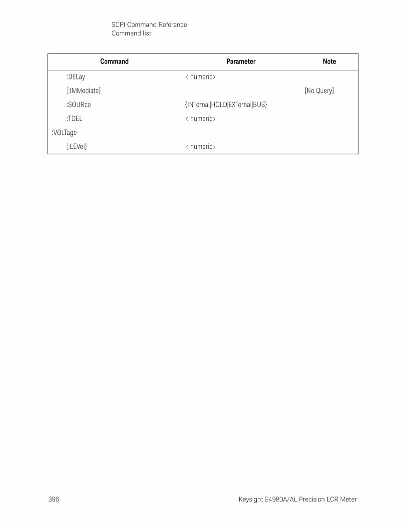
396 Keysight E4980A/AL Precision LCR Meter
SCPI Command ReferenceCommand list
10-
:DELay < numeric>
[:IMMediate] [No Query]
:SOURce {INTernal|HOLD|EXTernal|BUS}
:TDEL < numeric>
:VOLTage
[:LEVel] < numeric>
Command Parameter Note

Keysight E4980A/AL Precision LCR Meter 397
SCPI Command ReferenceCommand list
Softkey Functions
Key Operation Function SCPI Command
[DC Bias] Turns ON/OFF DC bias :BIAS:STAT
[DC Source] Turns ON/OFF DC Source :SOUR:DCS:STAT
[Display Format]
BIN COUNT
COUNT
COUNT OFF
Turns ON/OFF the BIN count function :COMP:BIN:COUN:STAT OFF
COUNT ON
Turns ON/OFF the BIN count function :COMP:BIN:COUN:STAT ON
RESET COUNT
Clears all BIN counts :COMP:BIN:COUN:CLE
BIN No.
COMP
OFF Turns OFFthe comparator function COMP:STAT OFF
ON Turns ON the comparator function COMP:STAT ON
DISPLAY BLANK
Enables display update :DISP:ENAB
LIST SWEEP
DISPLAY BLANK
Enables display update :DISP:ENAB
LIST TABLE
NEXT PAGE
Displays next page
PREV PAGE
Displays previous page
MODE
SEQ Selects the sweep mode for the list sweep measurement function
:LIST:MODE SEQ
STEP Selects the sweep mode for the list sweep measurement function
:LIST:MODE STEP
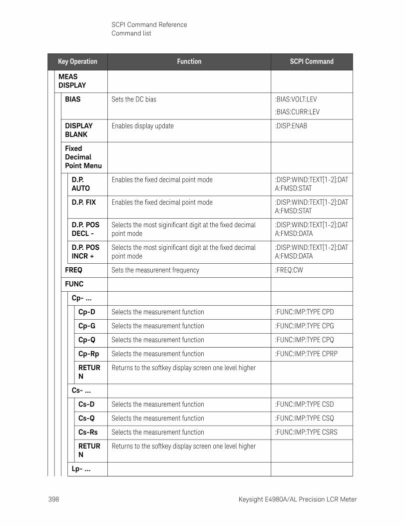
398 Keysight E4980A/AL Precision LCR Meter
SCPI Command ReferenceCommand list
10-
MEAS DISPLAY
BIAS Sets the DC bias :BIAS:VOLT:LEV
:BIAS:CURR:LEV
DISPLAY BLANK
Enables display update :DISP:ENAB
Fixed Decimal Point Menu
D.P. AUTO
Enables the fixed decimal point mode :DISP:WIND:TEXT[1-2]:DATA:FMSD:STAT
D.P. FIX Enables the fixed decimal point mode :DISP:WIND:TEXT[1-2]:DATA:FMSD:STAT
D.P. POS DECL -
Selects the most siginificant digit at the fixed decimal point mode
:DISP:WIND:TEXT[1-2]:DATA:FMSD:DATA
D.P. POS INCR +
Selects the most siginificant digit at the fixed decimal point mode
:DISP:WIND:TEXT[1-2]:DATA:FMSD:DATA
FREQ Sets the measurenent frequency :FREQ:CW
FUNC
Cp- ...
Cp-D Selects the measurement function :FUNC:IMP:TYPE CPD
Cp-G Selects the measurement function :FUNC:IMP:TYPE CPG
Cp-Q Selects the measurement function :FUNC:IMP:TYPE CPQ
Cp-Rp Selects the measurement function :FUNC:IMP:TYPE CPRP
RETURN
Returns to the softkey display screen one level higher
Cs- ...
Cs-D Selects the measurement function :FUNC:IMP:TYPE CSD
Cs-Q Selects the measurement function :FUNC:IMP:TYPE CSQ
Cs-Rs Selects the measurement function :FUNC:IMP:TYPE CSRS
RETURN
Returns to the softkey display screen one level higher
Lp- ...
Key Operation Function SCPI Command
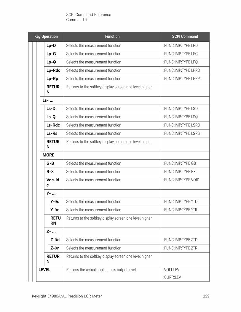
Keysight E4980A/AL Precision LCR Meter 399
SCPI Command ReferenceCommand list
Lp-D Selects the measurement function :FUNC:IMP:TYPE LPD
Lp-G Selects the measurement function :FUNC:IMP:TYPE LPG
Lp-Q Selects the measurement function :FUNC:IMP:TYPE LPQ
Lp-Rdc Selects the measurement function :FUNC:IMP:TYPE LPRD
Lp-Rp Selects the measurement function :FUNC:IMP:TYPE LPRP
RETURN
Returns to the softkey display screen one level higher
Ls- ...
Ls-D Selects the measurement function :FUNC:IMP:TYPE LSD
Ls-Q Selects the measurement function :FUNC:IMP:TYPE LSQ
Ls-Rdc Selects the measurement function :FUNC:IMP:TYPE LSRD
Ls-Rs Selects the measurement function :FUNC:IMP:TYPE LSRS
RETURN
Returns to the softkey display screen one level higher
MORE
G-B Selects the measurement function :FUNC:IMP:TYPE GB
R-X Selects the measurement function :FUNC:IMP:TYPE RX
Vdc-Idc
Selects the measurement function :FUNC:IMP:TYPE VDID
Y- ...
Y-d Selects the measurement function :FUNC:IMP:TYPE YTD
Y-r Selects the measurement function :FUNC:IMP:TYPE YTR
RETURN
Returns to the softkey display screen one level higher
Z- ...
Z-d Selects the measurement function :FUNC:IMP:TYPE ZTD
Z-r Selects the measurement function :FUNC:IMP:TYPE ZTR
RETURN
Returns to the softkey display screen one level higher
LEVEL Returns the actual applied bias output level :VOLT:LEV
:CURR:LEV
Key Operation Function SCPI Command
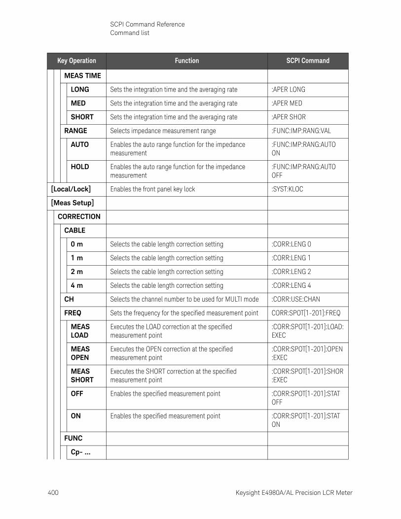
400 Keysight E4980A/AL Precision LCR Meter
SCPI Command ReferenceCommand list
10-
MEAS TIME
LONG Sets the integration time and the averaging rate :APER LONG
MED Sets the integration time and the averaging rate :APER MED
SHORT Sets the integration time and the averaging rate :APER SHOR
RANGE Selects impedance measurement range :FUNC:IMP:RANG:VAL
AUTO Enables the auto range function for the impedance measurement
:FUNC:IMP:RANG:AUTO ON
HOLD Enables the auto range function for the impedance measurement
:FUNC:IMP:RANG:AUTO OFF
[Local/Lock] Enables the front panel key lock :SYST:KLOC
[Meas Setup]
CORRECTION
CABLE
0 m Selects the cable length correction setting :CORR:LENG 0
1 m Selects the cable length correction setting :CORR:LENG 1
2 m Selects the cable length correction setting :CORR:LENG 2
4 m Selects the cable length correction setting :CORR:LENG 4
CH Selects the channel number to be used for MULTI mode :CORR:USE:CHAN
FREQ Sets the frequency for the specified measurement point CORR:SPOT[1-201]:FREQ
MEAS LOAD
Executes the LOAD correction at the specified measurement point
:CORR:SPOT[1-201]:LOAD:EXEC
MEAS OPEN
Executes the OPEN correction at the specified measurement point
:CORR:SPOT[1-201]:OPEN:EXEC
MEAS SHORT
Executes the SHORT correction at the specified measurement point
:CORR:SPOT[1-201]:SHOR:EXEC
OFF Enables the specified measurement point :CORR:SPOT[1-201]:STAT OFF
ON Enables the specified measurement point :CORR:SPOT[1-201]:STAT ON
FUNC
Cp- ...
Key Operation Function SCPI Command
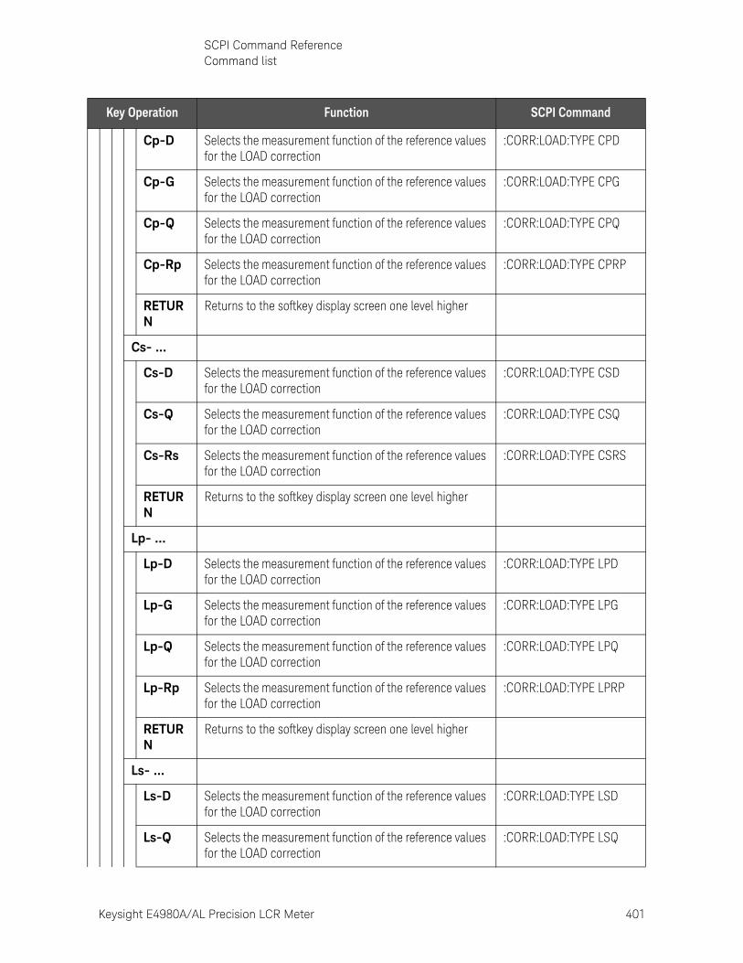
Keysight E4980A/AL Precision LCR Meter 401
SCPI Command ReferenceCommand list
Cp-D Selects the measurement function of the reference values for the LOAD correction
:CORR:LOAD:TYPE CPD
Cp-G Selects the measurement function of the reference values for the LOAD correction
:CORR:LOAD:TYPE CPG
Cp-Q Selects the measurement function of the reference values for the LOAD correction
:CORR:LOAD:TYPE CPQ
Cp-Rp Selects the measurement function of the reference values for the LOAD correction
:CORR:LOAD:TYPE CPRP
RETURN
Returns to the softkey display screen one level higher
Cs- ...
Cs-D Selects the measurement function of the reference values for the LOAD correction
:CORR:LOAD:TYPE CSD
Cs-Q Selects the measurement function of the reference values for the LOAD correction
:CORR:LOAD:TYPE CSQ
Cs-Rs Selects the measurement function of the reference values for the LOAD correction
:CORR:LOAD:TYPE CSRS
RETURN
Returns to the softkey display screen one level higher
Lp- ...
Lp-D Selects the measurement function of the reference values for the LOAD correction
:CORR:LOAD:TYPE LPD
Lp-G Selects the measurement function of the reference values for the LOAD correction
:CORR:LOAD:TYPE LPG
Lp-Q Selects the measurement function of the reference values for the LOAD correction
:CORR:LOAD:TYPE LPQ
Lp-Rp Selects the measurement function of the reference values for the LOAD correction
:CORR:LOAD:TYPE LPRP
RETURN
Returns to the softkey display screen one level higher
Ls- ...
Ls-D Selects the measurement function of the reference values for the LOAD correction
:CORR:LOAD:TYPE LSD
Ls-Q Selects the measurement function of the reference values for the LOAD correction
:CORR:LOAD:TYPE LSQ
Key Operation Function SCPI Command
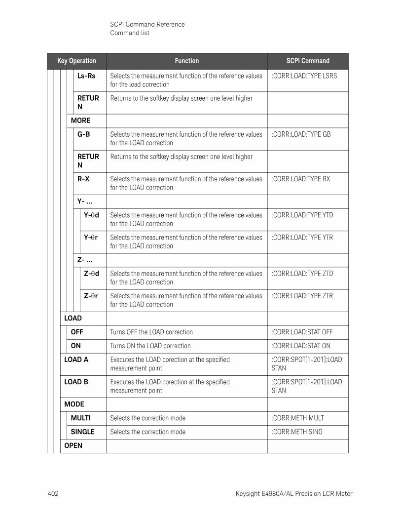
402 Keysight E4980A/AL Precision LCR Meter
SCPI Command ReferenceCommand list
10-
Ls-Rs Selects the measurement function of the reference values for the load correction
:CORR:LOAD:TYPE LSRS
RETURN
Returns to the softkey display screen one level higher
MORE
G-B Selects the measurement function of the reference values for the LOAD correction
:CORR:LOAD:TYPE GB
RETURN
Returns to the softkey display screen one level higher
R-X Selects the measurement function of the reference values for the LOAD correction
:CORR:LOAD:TYPE RX
Y- ...
Y-d Selects the measurement function of the reference values for the LOAD correction
:CORR:LOAD:TYPE YTD
Y-r Selects the measurement function of the reference values for the LOAD correction
:CORR:LOAD:TYPE YTR
Z- ...
Z-d Selects the measurement function of the reference values for the LOAD correction
:CORR:LOAD:TYPE ZTD
Z-r Selects the measurement function of the reference values for the LOAD correction
:CORR:LOAD:TYPE ZTR
LOAD
OFF Turns OFF the LOAD correction :CORR:LOAD:STAT OFF
ON Turns ON the LOAD correction :CORR:LOAD:STAT ON
LOAD A Executes the LOAD corection at the specified measurement point
:CORR:SPOT[1-201]:LOAD:STAN
LOAD B Executes the LOAD corection at the specified measurement point
:CORR:SPOT[1-201]:LOAD:STAN
MODE
MULTI Selects the correction mode :CORR:METH MULT
SINGLE Selects the correction mode :CORR:METH SING
OPEN
Key Operation Function SCPI Command
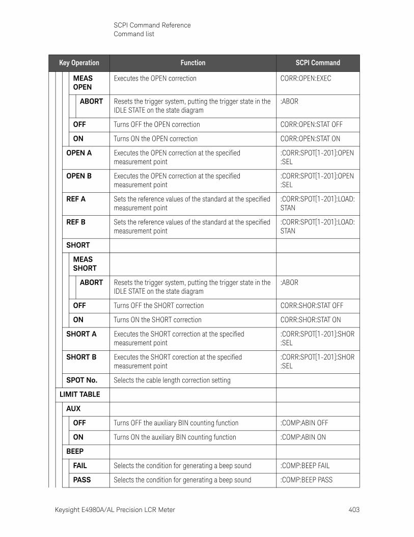
Keysight E4980A/AL Precision LCR Meter 403
SCPI Command ReferenceCommand list
MEAS OPEN
Executes the OPEN correction CORR:OPEN:EXEC
ABORT Resets the trigger system, putting the trigger state in the IDLE STATE on the state diagram
:ABOR
OFF Turns OFF the OPEN correction CORR:OPEN:STAT OFF
ON Turns ON the OPEN correction CORR:OPEN:STAT ON
OPEN A Executes the OPEN correction at the specified measurement point
:CORR:SPOT[1-201]:OPEN:SEL
OPEN B Executes the OPEN correction at the specified measurement point
:CORR:SPOT[1-201]:OPEN:SEL
REF A Sets the reference values of the standard at the specified measurement point
:CORR:SPOT[1-201]:LOAD:STAN
REF B Sets the reference values of the standard at the specified measurement point
:CORR:SPOT[1-201]:LOAD:STAN
SHORT
MEAS SHORT
ABORT Resets the trigger system, putting the trigger state in the IDLE STATE on the state diagram
:ABOR
OFF Turns OFF the SHORT correction CORR:SHOR:STAT OFF
ON Turns ON the SHORT correction CORR:SHOR:STAT ON
SHORT A Executes the SHORT correction at the specified measurement point
:CORR:SPOT[1-201]:SHOR:SEL
SHORT B Executes the SHORT corection at the specified measurement point
:CORR:SPOT[1-201]:SHOR:SEL
SPOT No. Selects the cable length correction setting
LIMIT TABLE
AUX
OFF Turns OFF the auxiliary BIN counting function :COMP:ABIN OFF
ON Turns ON the auxiliary BIN counting function :COMP:ABIN ON
BEEP
FAIL Selects the condition for generating a beep sound :COMP:BEEP FAIL
PASS Selects the condition for generating a beep sound :COMP:BEEP PASS
Key Operation Function SCPI Command
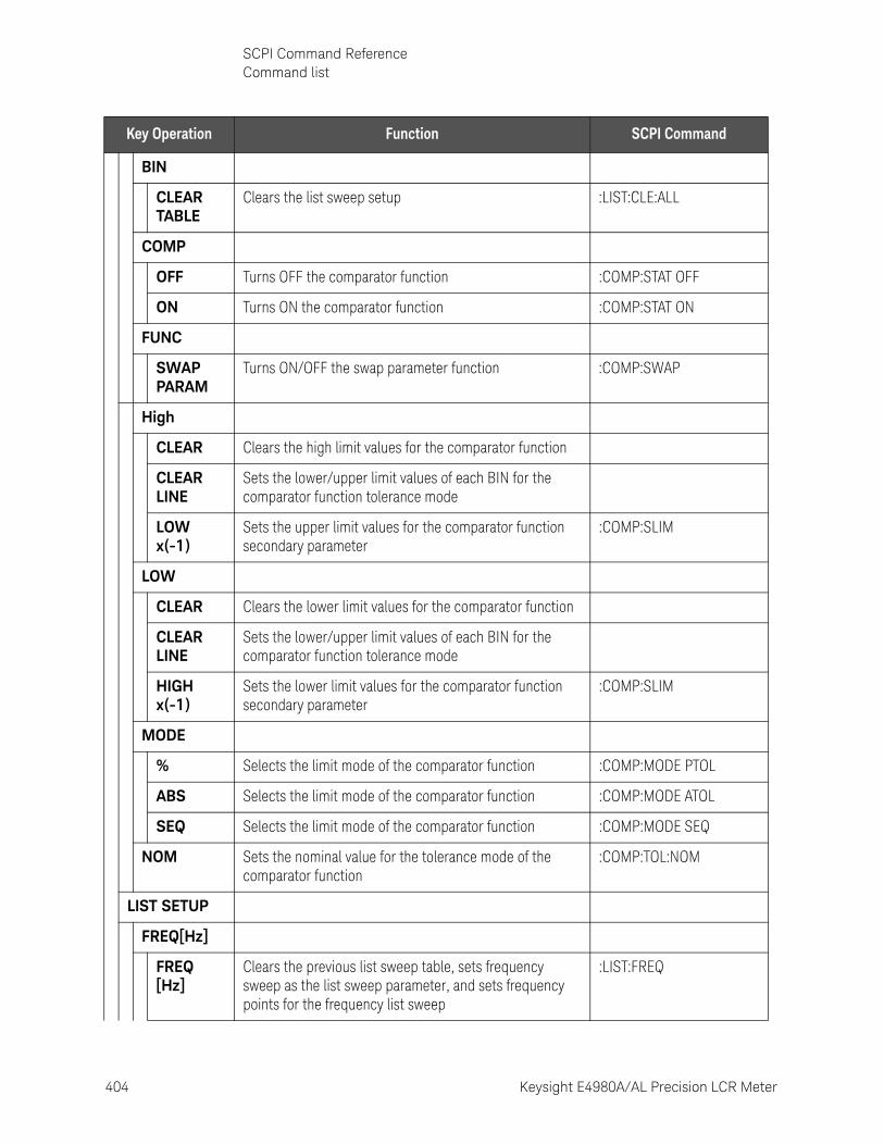
404 Keysight E4980A/AL Precision LCR Meter
SCPI Command ReferenceCommand list
10-
BIN
CLEAR TABLE
Clears the list sweep setup :LIST:CLE:ALL
COMP
OFF Turns OFF the comparator function :COMP:STAT OFF
ON Turns ON the comparator function :COMP:STAT ON
FUNC
SWAP PARAM
Turns ON/OFF the swap parameter function :COMP:SWAP
High
CLEAR Clears the high limit values for the comparator function
CLEAR LINE
Sets the lower/upper limit values of each BIN for the comparator function tolerance mode
LOW x(-1)
Sets the upper limit values for the comparator function secondary parameter
:COMP:SLIM
LOW
CLEAR Clears the lower limit values for the comparator function
CLEAR LINE
Sets the lower/upper limit values of each BIN for the comparator function tolerance mode
HIGH x(-1)
Sets the lower limit values for the comparator function secondary parameter
:COMP:SLIM
MODE
% Selects the limit mode of the comparator function :COMP:MODE PTOL
ABS Selects the limit mode of the comparator function :COMP:MODE ATOL
SEQ Selects the limit mode of the comparator function :COMP:MODE SEQ
NOM Sets the nominal value for the tolerance mode of the comparator function
:COMP:TOL:NOM
LIST SETUP
FREQ[Hz]
FREQ [Hz]
Clears the previous list sweep table, sets frequency sweep as the list sweep parameter, and sets frequency points for the frequency list sweep
:LIST:FREQ
Key Operation Function SCPI Command
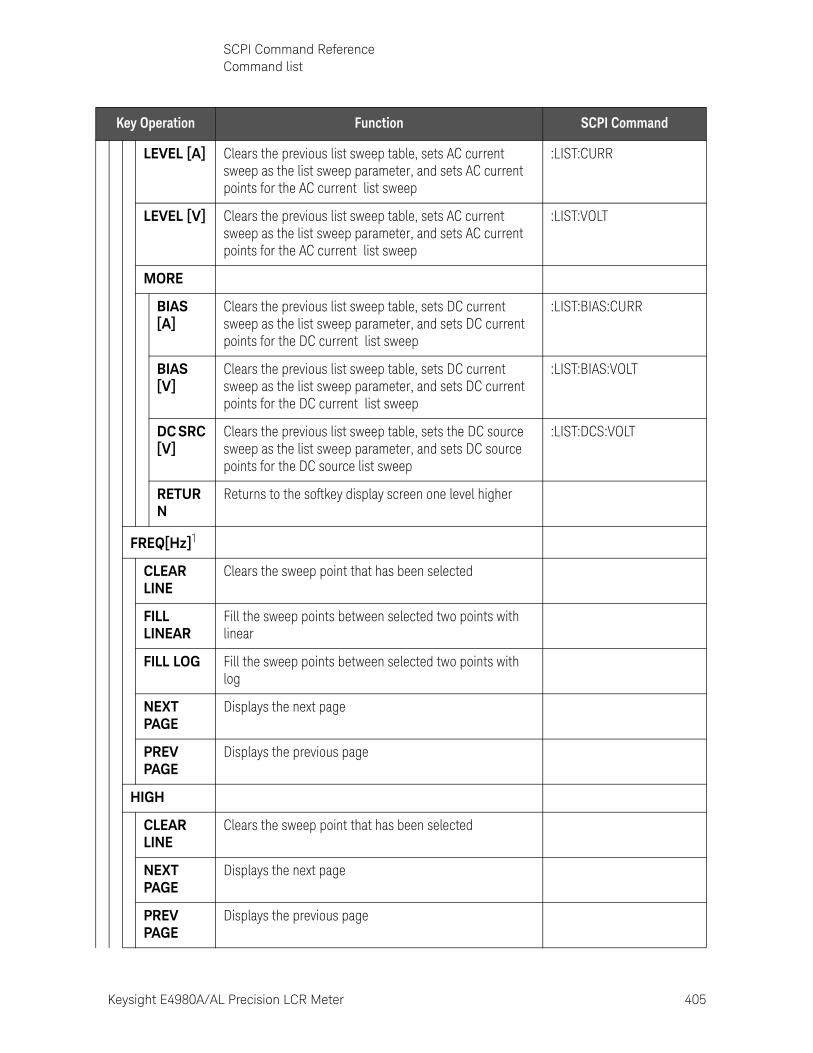
Keysight E4980A/AL Precision LCR Meter 405
SCPI Command ReferenceCommand list
LEVEL [A] Clears the previous list sweep table, sets AC current sweep as the list sweep parameter, and sets AC current points for the AC current list sweep
:LIST:CURR
LEVEL [V] Clears the previous list sweep table, sets AC current sweep as the list sweep parameter, and sets AC current points for the AC current list sweep
:LIST:VOLT
MORE
BIAS [A]
Clears the previous list sweep table, sets DC current sweep as the list sweep parameter, and sets DC current points for the DC current list sweep
:LIST:BIAS:CURR
BIAS [V]
Clears the previous list sweep table, sets DC current sweep as the list sweep parameter, and sets DC current points for the DC current list sweep
:LIST:BIAS:VOLT
DC SRC [V]
Clears the previous list sweep table, sets the DC source sweep as the list sweep parameter, and sets DC source points for the DC source list sweep
:LIST:DCS:VOLT
RETURN
Returns to the softkey display screen one level higher
FREQ[Hz]1
CLEAR LINE
Clears the sweep point that has been selected
FILL LINEAR
Fill the sweep points between selected two points with linear
FILL LOG Fill the sweep points between selected two points with log
NEXT PAGE
Displays the next page
PREV PAGE
Displays the previous page
HIGH
CLEAR LINE
Clears the sweep point that has been selected
NEXT PAGE
Displays the next page
PREV PAGE
Displays the previous page
Key Operation Function SCPI Command
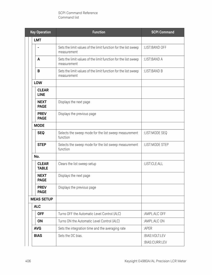
406 Keysight E4980A/AL Precision LCR Meter
SCPI Command ReferenceCommand list
10-
LMT
- Sets the limit values of the limit function for the list sweep measurement
:LIST:BAND OFF
A Sets the limit values of the limit function for the list sweep measurement
:LIST:BAND A
B Sets the limit values of the limit function for the list sweep measurement
:LIST:BAND B
LOW
CLEAR LINE
NEXT PAGE
Displays the next page
PREV PAGE
Displays the previous page
MODE
SEQ Selects the sweep mode for the list sweep measurement function
:LIST:MODE SEQ
STEP Selects the sweep mode for the list sweep measurement function
:LIST:MODE STEP
No.
CLEAR TABLE
Clears the list sweep setup :LIST:CLE:ALL
NEXT PAGE
Displays the next page
PREV PAGE
Displays the previous page
MEAS SETUP
ALC
OFF Turns OFF the Automatic Level Control (ALC) :AMPL:ALC OFF
ON Turns ON the Automatic Level Control (ALC) :AMPL:ALC ON
AVG Sets the integration time and the averaging rate :APER
BIAS Sets the DC bias. :BIAS:VOLT:LEV
:BIAS:CURR:LEV
Key Operation Function SCPI Command
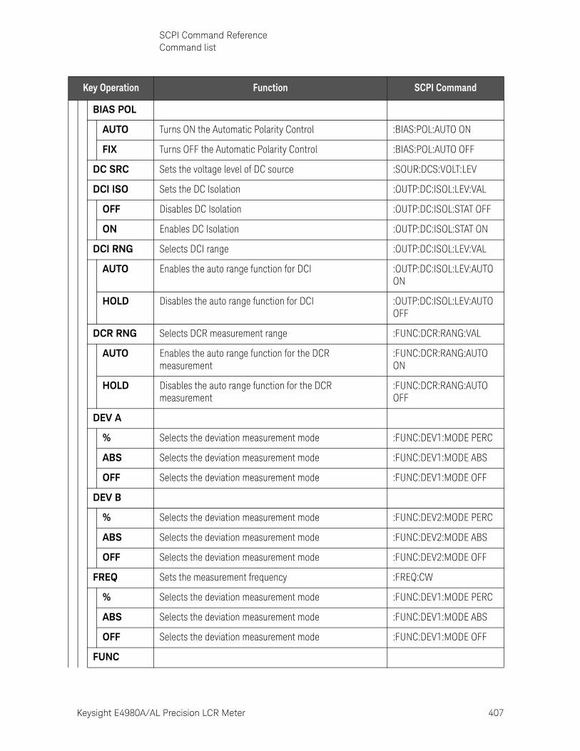
Keysight E4980A/AL Precision LCR Meter 407
SCPI Command ReferenceCommand list
BIAS POL
AUTO Turns ON the Automatic Polarity Control :BIAS:POL:AUTO ON
FIX Turns OFF the Automatic Polarity Control :BIAS:POL:AUTO OFF
DC SRC Sets the voltage level of DC source :SOUR:DCS:VOLT:LEV
DCI ISO Sets the DC Isolation :OUTP:DC:ISOL:LEV:VAL
OFF Disables DC Isolation :OUTP:DC:ISOL:STAT OFF
ON Enables DC Isolation :OUTP:DC:ISOL:STAT ON
DCI RNG Selects DCI range :OUTP:DC:ISOL:LEV:VAL
AUTO Enables the auto range function for DCI :OUTP:DC:ISOL:LEV:AUTO ON
HOLD Disables the auto range function for DCI :OUTP:DC:ISOL:LEV:AUTO OFF
DCR RNG Selects DCR measurement range :FUNC:DCR:RANG:VAL
AUTO Enables the auto range function for the DCR measurement
:FUNC:DCR:RANG:AUTO ON
HOLD Disables the auto range function for the DCR measurement
:FUNC:DCR:RANG:AUTO OFF
DEV A
% Selects the deviation measurement mode :FUNC:DEV1:MODE PERC
ABS Selects the deviation measurement mode :FUNC:DEV1:MODE ABS
OFF Selects the deviation measurement mode :FUNC:DEV1:MODE OFF
DEV B
% Selects the deviation measurement mode :FUNC:DEV2:MODE PERC
ABS Selects the deviation measurement mode :FUNC:DEV2:MODE ABS
OFF Selects the deviation measurement mode :FUNC:DEV2:MODE OFF
FREQ Sets the measurement frequency :FREQ:CW
% Selects the deviation measurement mode :FUNC:DEV1:MODE PERC
ABS Selects the deviation measurement mode :FUNC:DEV1:MODE ABS
OFF Selects the deviation measurement mode :FUNC:DEV1:MODE OFF
FUNC
Key Operation Function SCPI Command
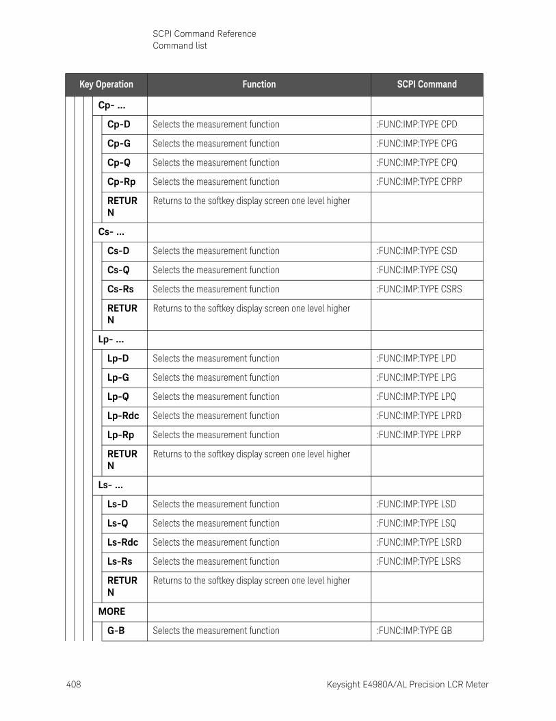
408 Keysight E4980A/AL Precision LCR Meter
SCPI Command ReferenceCommand list
10-
Cp- ...
Cp-D Selects the measurement function :FUNC:IMP:TYPE CPD
Cp-G Selects the measurement function :FUNC:IMP:TYPE CPG
Cp-Q Selects the measurement function :FUNC:IMP:TYPE CPQ
Cp-Rp Selects the measurement function :FUNC:IMP:TYPE CPRP
RETURN
Returns to the softkey display screen one level higher
Cs- ...
Cs-D Selects the measurement function :FUNC:IMP:TYPE CSD
Cs-Q Selects the measurement function :FUNC:IMP:TYPE CSQ
Cs-Rs Selects the measurement function :FUNC:IMP:TYPE CSRS
RETURN
Returns to the softkey display screen one level higher
Lp- ...
Lp-D Selects the measurement function :FUNC:IMP:TYPE LPD
Lp-G Selects the measurement function :FUNC:IMP:TYPE LPG
Lp-Q Selects the measurement function :FUNC:IMP:TYPE LPQ
Lp-Rdc Selects the measurement function :FUNC:IMP:TYPE LPRD
Lp-Rp Selects the measurement function :FUNC:IMP:TYPE LPRP
RETURN
Returns to the softkey display screen one level higher
Ls- ...
Ls-D Selects the measurement function :FUNC:IMP:TYPE LSD
Ls-Q Selects the measurement function :FUNC:IMP:TYPE LSQ
Ls-Rdc Selects the measurement function :FUNC:IMP:TYPE LSRD
Ls-Rs Selects the measurement function :FUNC:IMP:TYPE LSRS
RETURN
Returns to the softkey display screen one level higher
MORE
G-B Selects the measurement function :FUNC:IMP:TYPE GB
Key Operation Function SCPI Command
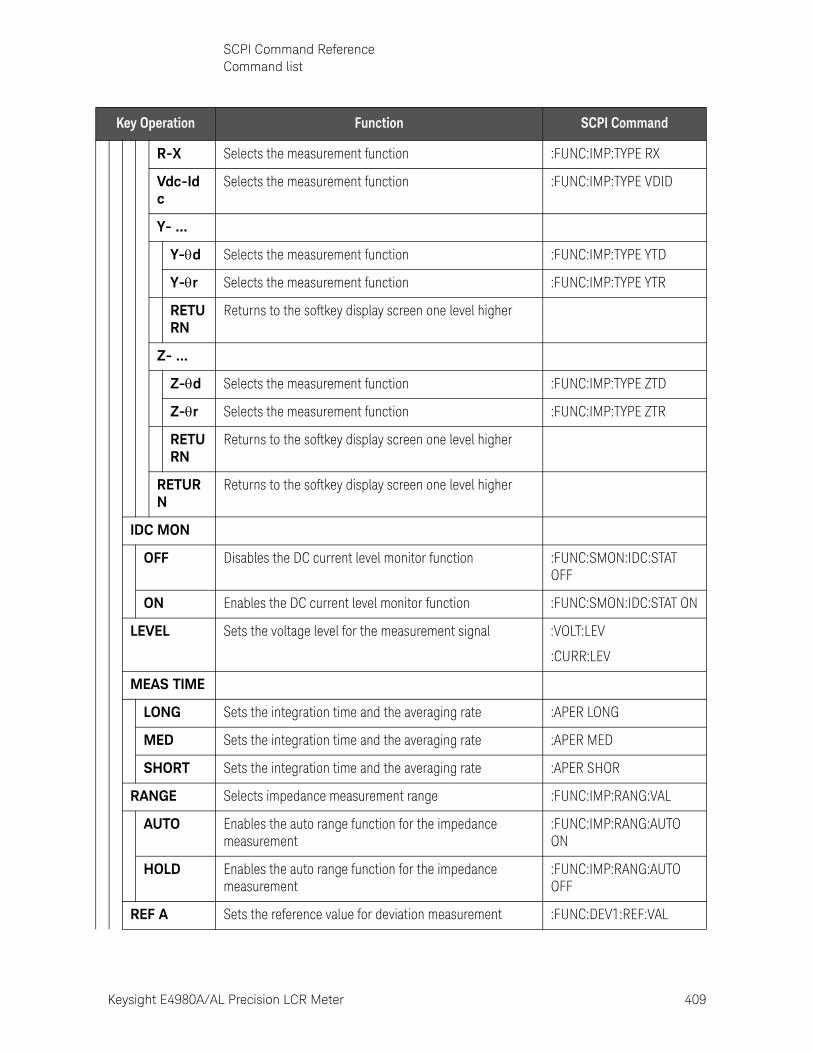
Keysight E4980A/AL Precision LCR Meter 409
SCPI Command ReferenceCommand list
R-X Selects the measurement function :FUNC:IMP:TYPE RX
Vdc-Idc
Selects the measurement function :FUNC:IMP:TYPE VDID
Y- ...
Y-d Selects the measurement function :FUNC:IMP:TYPE YTD
Y-r Selects the measurement function :FUNC:IMP:TYPE YTR
RETURN
Returns to the softkey display screen one level higher
Z- ...
Z-d Selects the measurement function :FUNC:IMP:TYPE ZTD
Z-r Selects the measurement function :FUNC:IMP:TYPE ZTR
RETURN
Returns to the softkey display screen one level higher
RETURN
Returns to the softkey display screen one level higher
IDC MON
OFF Disables the DC current level monitor function :FUNC:SMON:IDC:STAT OFF
ON Enables the DC current level monitor function :FUNC:SMON:IDC:STAT ON
LEVEL Sets the voltage level for the measurement signal :VOLT:LEV
:CURR:LEV
MEAS TIME
LONG Sets the integration time and the averaging rate :APER LONG
MED Sets the integration time and the averaging rate :APER MED
SHORT Sets the integration time and the averaging rate :APER SHOR
RANGE Selects impedance measurement range :FUNC:IMP:RANG:VAL
AUTO Enables the auto range function for the impedance measurement
:FUNC:IMP:RANG:AUTO ON
HOLD Enables the auto range function for the impedance measurement
:FUNC:IMP:RANG:AUTO OFF
REF A Sets the reference value for deviation measurement :FUNC:DEV1:REF:VAL
Key Operation Function SCPI Command
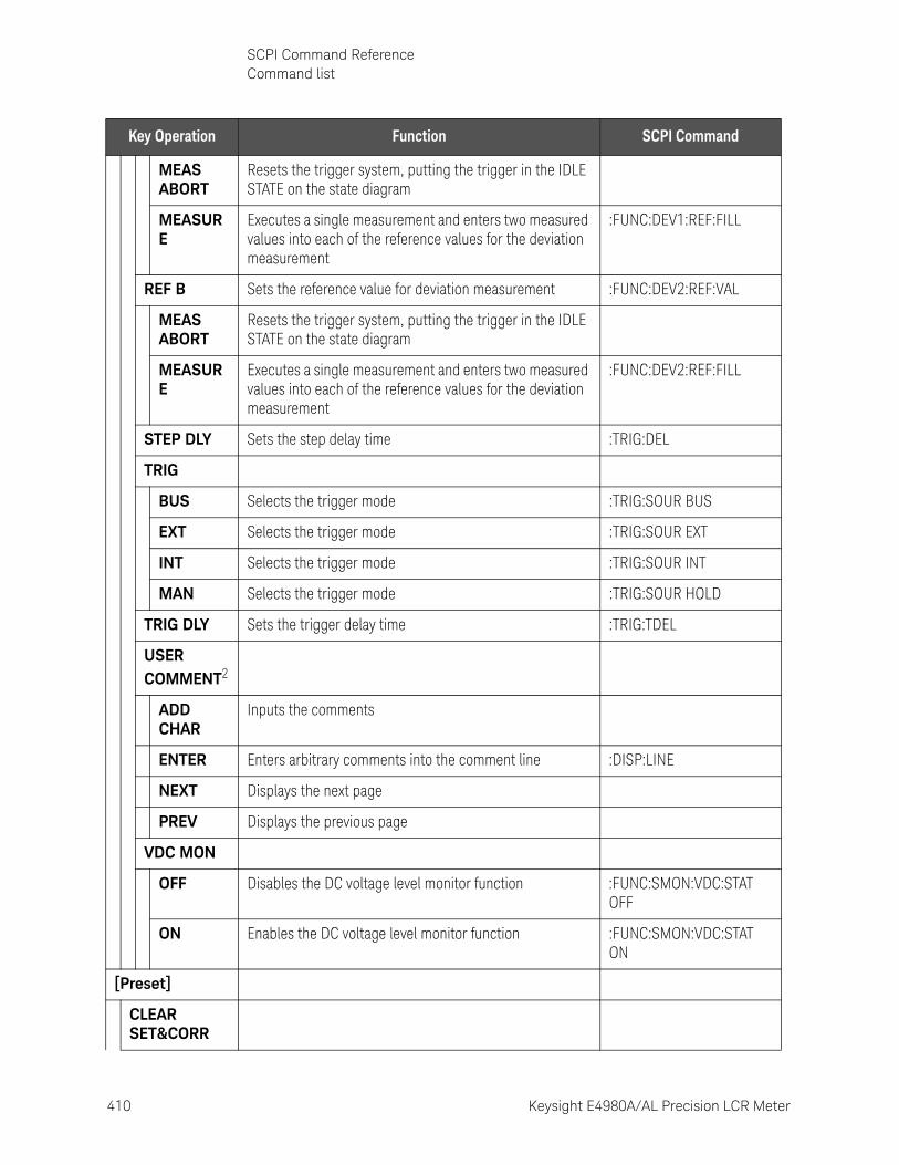
410 Keysight E4980A/AL Precision LCR Meter
SCPI Command ReferenceCommand list
10-
MEAS ABORT
Resets the trigger system, putting the trigger in the IDLE STATE on the state diagram
MEASURE
Executes a single measurement and enters two measured values into each of the reference values for the deviation measurement
:FUNC:DEV1:REF:FILL
REF B Sets the reference value for deviation measurement :FUNC:DEV2:REF:VAL
MEAS ABORT
Resets the trigger system, putting the trigger in the IDLE STATE on the state diagram
MEASURE
Executes a single measurement and enters two measured values into each of the reference values for the deviation measurement
:FUNC:DEV2:REF:FILL
STEP DLY Sets the step delay time :TRIG:DEL
TRIG
BUS Selects the trigger mode :TRIG:SOUR BUS
EXT Selects the trigger mode :TRIG:SOUR EXT
INT Selects the trigger mode :TRIG:SOUR INT
MAN Selects the trigger mode :TRIG:SOUR HOLD
TRIG DLY Sets the trigger delay time :TRIG:TDEL
USER COMMENT2
ADD CHAR
Inputs the comments
ENTER Enters arbitrary comments into the comment line :DISP:LINE
NEXT Displays the next page
PREV Displays the previous page
VDC MON
OFF Disables the DC voltage level monitor function :FUNC:SMON:VDC:STAT OFF
ON Enables the DC voltage level monitor function :FUNC:SMON:VDC:STAT ON
[Preset]
CLEAR SET&CORR
Key Operation Function SCPI Command
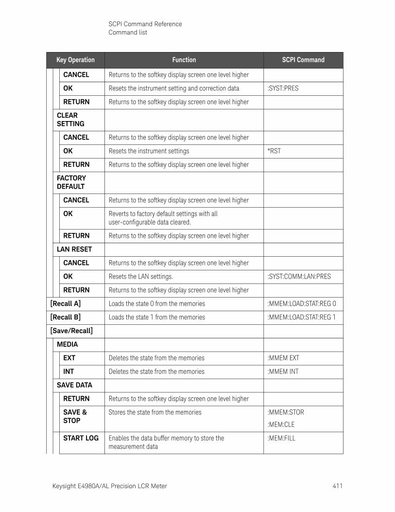
Keysight E4980A/AL Precision LCR Meter 411
SCPI Command ReferenceCommand list
CANCEL Returns to the softkey display screen one level higher
OK Resets the instrument setting and correction data :SYST:PRES
RETURN Returns to the softkey display screen one level higher
CLEAR SETTING
CANCEL Returns to the softkey display screen one level higher
OK Resets the instrument settings *RST
RETURN Returns to the softkey display screen one level higher
FACTORY DEFAULT
CANCEL Returns to the softkey display screen one level higher
OK Reverts to factory default settings with all user-configurable data cleared.
RETURN Returns to the softkey display screen one level higher
LAN RESET
CANCEL Returns to the softkey display screen one level higher
OK Resets the LAN settings. :SYST:COMM:LAN:PRES
RETURN Returns to the softkey display screen one level higher
[Recall A] Loads the state 0 from the memories :MMEM:LOAD:STAT:REG 0
[Recall B] Loads the state 1 from the memories :MMEM:LOAD:STAT:REG 1
[Save/Recall]
MEDIA
EXT Deletes the state from the memories :MMEM EXT
INT Deletes the state from the memories :MMEM INT
SAVE DATA
RETURN Returns to the softkey display screen one level higher
SAVE & STOP
Stores the state from the memories :MMEM:STOR
:MEM:CLE
START LOG Enables the data buffer memory to store the measurement data
:MEM:FILL
Key Operation Function SCPI Command
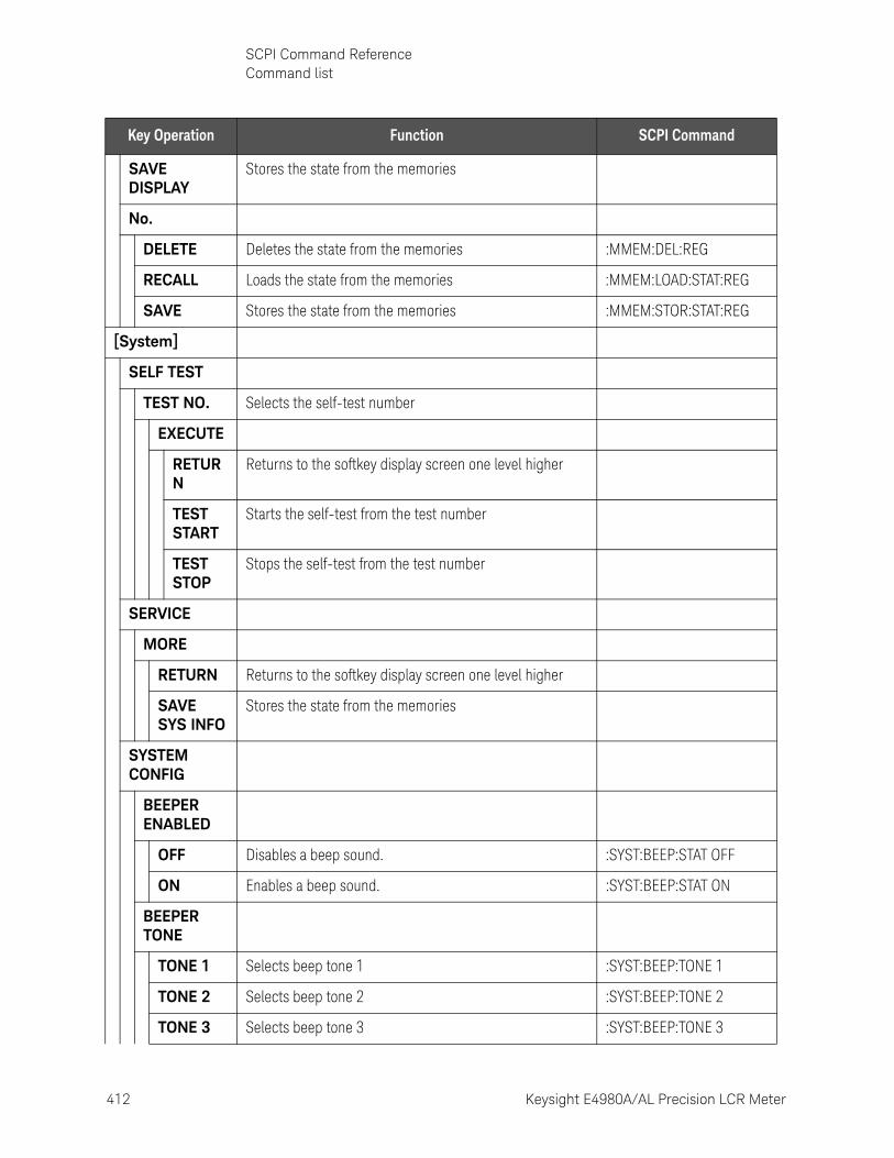
412 Keysight E4980A/AL Precision LCR Meter
SCPI Command ReferenceCommand list
10-
SAVE DISPLAY
Stores the state from the memories
No.
DELETE Deletes the state from the memories :MMEM:DEL:REG
RECALL Loads the state from the memories :MMEM:LOAD:STAT:REG
SAVE Stores the state from the memories :MMEM:STOR:STAT:REG
[System]
SELF TEST
TEST NO. Selects the self-test number
EXECUTE
RETURN
Returns to the softkey display screen one level higher
TEST START
Starts the self-test from the test number
TEST STOP
Stops the self-test from the test number
SERVICE
MORE
RETURN Returns to the softkey display screen one level higher
SAVE SYS INFO
Stores the state from the memories
SYSTEM CONFIG
BEEPER ENABLED
OFF Disables a beep sound. :SYST:BEEP:STAT OFF
ON Enables a beep sound. :SYST:BEEP:STAT ON
BEEPER TONE
TONE 1 Selects beep tone 1 :SYST:BEEP:TONE 1
TONE 2 Selects beep tone 2 :SYST:BEEP:TONE 2
TONE 3 Selects beep tone 3 :SYST:BEEP:TONE 3
Key Operation Function SCPI Command
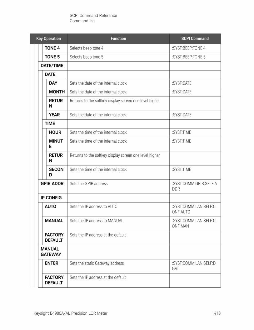
Keysight E4980A/AL Precision LCR Meter 413
SCPI Command ReferenceCommand list
TONE 4 Selects beep tone 4 :SYST:BEEP:TONE 4
TONE 5 Selects beep tone 5 :SYST:BEEP:TONE 5
DATE/TIME
DATE
DAY Sets the date of the internal clock :SYST:DATE
MONTH Sets the date of the internal clock :SYST:DATE
RETURN
Returns to the softkey display screen one level higher
YEAR Sets the date of the internal clock :SYST:DATE
TIME
HOUR Sets the time of the internal clock :SYST:TIME
MINUTE
Sets the time of the internal clock :SYST:TIME
RETURN
Returns to the softkey display screen one level higher
SECOND
Sets the time of the internal clock :SYST:TIME
GPIB ADDR Sets the GPIB address :SYST:COMM:GPIB:SELF:ADDR
IP CONFIG
AUTO Sets the IP address to AUTO :SYST:COMM:LAN:SELF:CONF AUTO
MANUAL Sets the IP address to MANUAL :SYST:COMM:LAN:SELF:CONF MAN
FACTORY DEFAULT
Sets the IP address at the default
MANUAL GATEWAY
ENTER Sets the static Gateway address :SYST:COMM:LAN:SELF:DGAT
FACTORY DEFAULT
Sets the IP address at the default
Key Operation Function SCPI Command
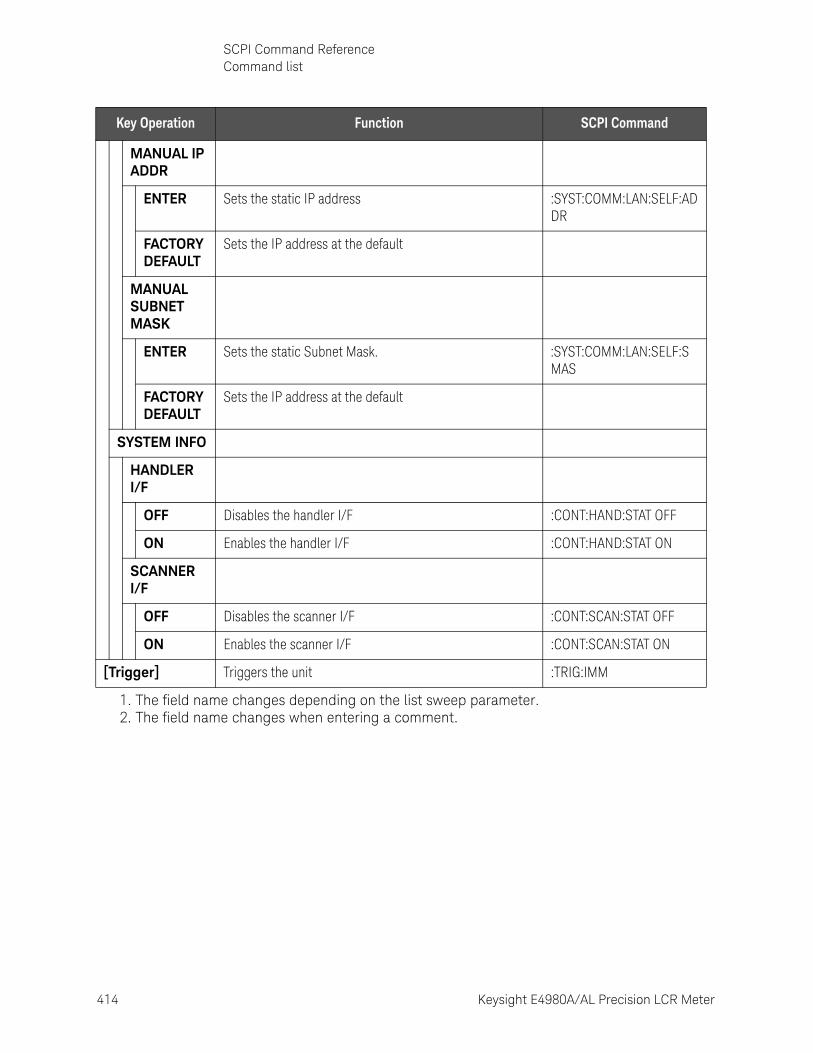
414 Keysight E4980A/AL Precision LCR Meter
SCPI Command ReferenceCommand list
10-
MANUAL IP ADDR
ENTER Sets the static IP address :SYST:COMM:LAN:SELF:ADDR
FACTORY DEFAULT
Sets the IP address at the default
MANUAL SUBNET MASK
ENTER Sets the static Subnet Mask. :SYST:COMM:LAN:SELF:SMAS
FACTORY DEFAULT
Sets the IP address at the default
SYSTEM INFO
HANDLER I/F
OFF Disables the handler I/F :CONT:HAND:STAT OFF
ON Enables the handler I/F :CONT:HAND:STAT ON
SCANNER I/F
OFF Disables the scanner I/F :CONT:SCAN:STAT OFF
ON Enables the scanner I/F :CONT:SCAN:STAT ON
[Trigger] Triggers the unit :TRIG:IMM
1. The field name changes depending on the list sweep parameter.2. The field name changes when entering a comment.
Key Operation Function SCPI Command
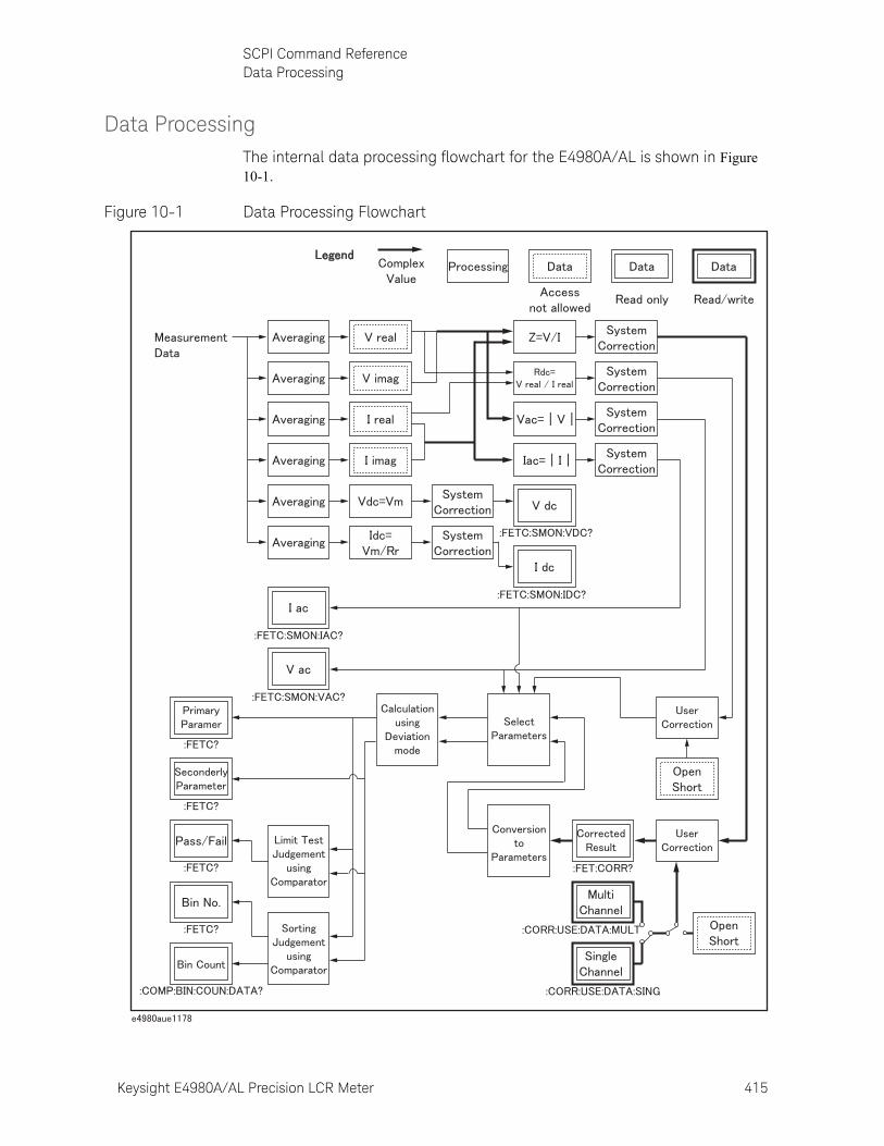
Keysight E4980A/AL Precision LCR Meter 415
SCPI Command ReferenceData Processing
Data ProcessingThe internal data processing flowchart for the E4980A/AL is shown in Figure 10-1.
Figure 10-1 Data Processing Flowchart

416 Keysight E4980A/AL Precision LCR Meter
SCPI Command ReferenceData Processing
10-
417
Keysight E4980A/AL Precision LCR Meter
User’s Guide
11 Specifications and Supplemental Information
For the specifications and supplemental information of the E4980A/AL Precision LCR meter, refer to the datasheet at http://literature.cdn.keysight.com/litweb/pdf/5989-4435EN.pdf

418 Keysight E4980A/AL Precision LCR Meter
Specifications and Supplemental Information
11-

419
Keysight E4980A/AL Precision LCR Meter
User’s Guide
12 Precautions for Use and Daily Checks
This chapter describes precautions to take when using the E4980A/AL and explains how to perform regular maintenance on the device.
Precautions for UseThis section describes the precautions to take in using the E4980A/AL.
Avoiding improper input from the front panel (key lock function)
When you do not need to operate the keys on the front panel, you can disable entry from the front panel keys (key lock function) to avoid improper input caused by touching the front panel keys accidentally.
The ON/OFF state of the key lock function is indicated by whether LOCK is displayed in the status display area. When LOCK is displayed, as indicated by 1 in Figure 12-1, the function is ON.
Figure 12-1 ON/OFF display of the key lock function (when ON)

420 Keysight E4980A/AL Precision LCR Meter
Precautions for Use and Daily ChecksPrecautions for Use
12-
Setup procedure
Step 1. Press the [Local/Lock] key on the front panel.
Step 2. Confirm that LOCK is displayed in the status display area in the lower-right corner of the LCD display.
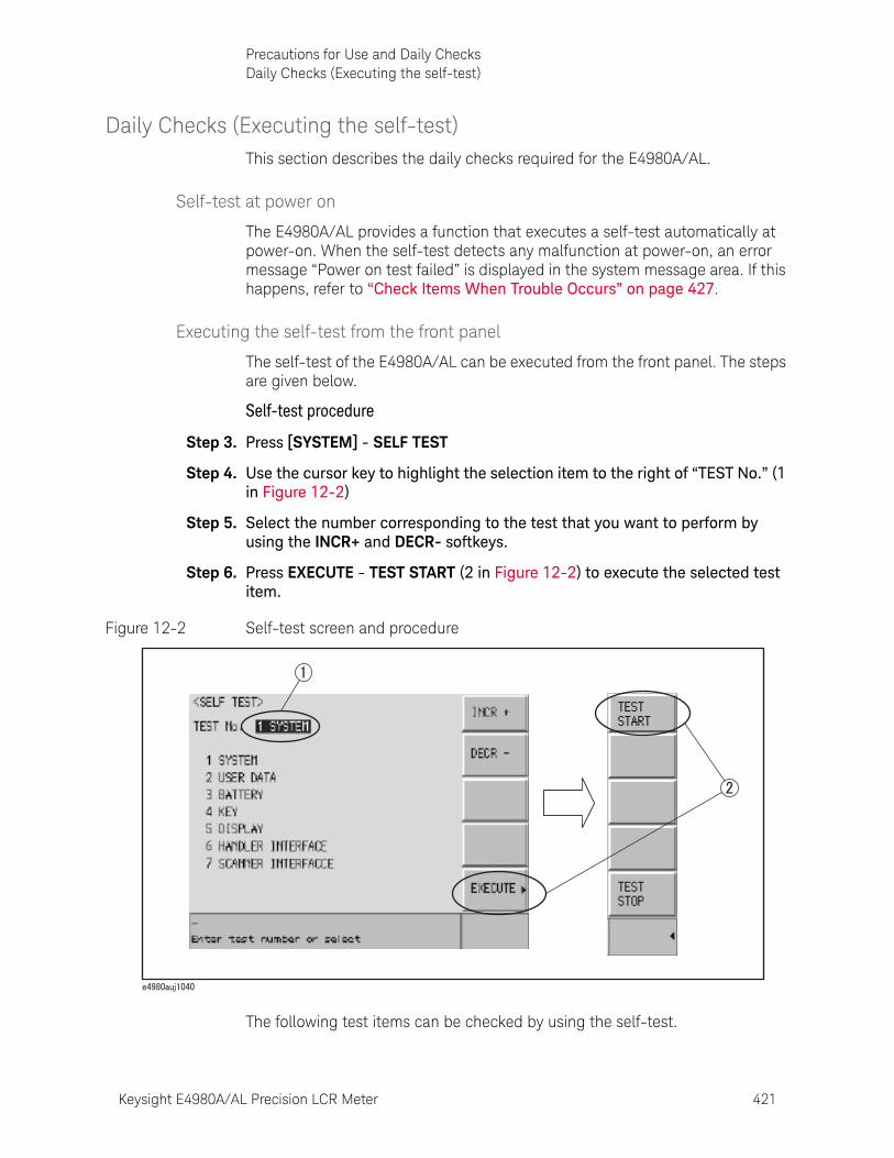
Keysight E4980A/AL Precision LCR Meter 421
Precautions for Use and Daily ChecksDaily Checks (Executing the self-test)
Daily Checks (Executing the self-test)This section describes the daily checks required for the E4980A/AL.
Self-test at power on
The E4980A/AL provides a function that executes a self-test automatically at power-on. When the self-test detects any malfunction at power-on, an error message “Power on test failed” is displayed in the system message area. If this happens, refer to “Check Items When Trouble Occurs” on page 427.
Executing the self-test from the front panel
The self-test of the E4980A/AL can be executed from the front panel. The steps are given below.
Self-test procedure
Step 3. Press [SYSTEM] - SELF TEST
Step 4. Use the cursor key to highlight the selection item to the right of “TEST No.” (1 in Figure 12-2)
Step 5. Select the number corresponding to the test that you want to perform by using the INCR+ and DECR- softkeys.
Step 6. Press EXECUTE - TEST START (2 in Figure 12-2) to execute the selected test item.
Figure 12-2 Self-test screen and procedure
The following test items can be checked by using the self-test.
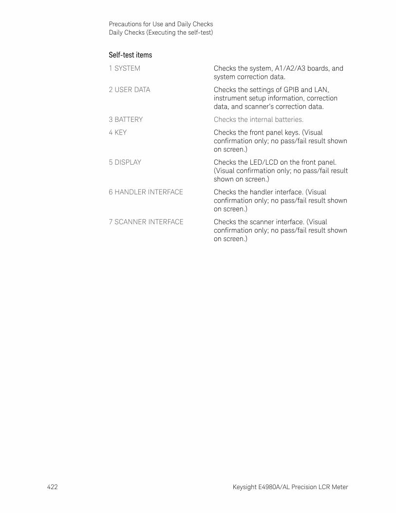
422 Keysight E4980A/AL Precision LCR Meter
Precautions for Use and Daily ChecksDaily Checks (Executing the self-test)
12-
Self-test items
1 SYSTEM Checks the system, A1/A2/A3 boards, and system correction data.
2 USER DATA Checks the settings of GPIB and LAN, instrument setup information, correction data, and scanner’s correction data.
3 BATTERY Checks the internal batteries.
4 KEY Checks the front panel keys. (Visual confirmation only; no pass/fail result shown on screen.)
5 DISPLAY Checks the LED/LCD on the front panel. (Visual confirmation only; no pass/fail result shown on screen.)
6 HANDLER INTERFACE Checks the handler interface. (Visual confirmation only; no pass/fail result shown on screen.)
7 SCANNER INTERFACE Checks the scanner interface. (Visual confirmation only; no pass/fail result shown on screen.)
Keysight E4980A/AL Precision LCR Meter 423
Precautions for Use and Daily ChecksCleaning this Instrument
Cleaning this InstrumentThis section explains how to clean the instrument.
Unknown Terminals/DC Source Ports
Unknown terminals and DC source ports (option 001) on the front panel of the E4980A are fitted with BNC Type connectors (m).Stains or other damage to these connectors would significantly affect the measurement accuracy. Please give attention to the following precautions.
• Always keep the connectors free from stains or dust.
• Do not touch the contact surface on the connectors.
• Do not plug damaged or scratched connectors into the test ports.
• Use compressed air to clean connectors. Do not use abrasives under any circumstance.
Cleaning Parts Other than Unknown Terminals and DC Source Ports
To remove stains on parts other than the unknown terminals and DC source ports, wipe them gently with a soft cloth that is dry or one that is wetted with a small amount of water and wrung tightly.
To protect yourself from electrical shock, be sure to unplug the power cable from the outlet before cleaning the instrument.
Never clean the internal components of the instrument.
424 Keysight E4980A/AL Precision LCR Meter
Precautions for Use and Daily ChecksCautions Applicable to Requesting Repair, Replacement, Regular Calibration, etc.
12-
Cautions Applicable to Requesting Repair, Replacement, Regular Calibration, etc.
Caution when Sending the Unit
If it is necessary to send the unit to a Service Center of Keysight Technologies, please follow the instructions below.
Equipment to be Sent
When requesting repair or regular calibration of the unit at our Service Center, send only the E4980A/AL main unit without any installed option. Unless specifically instructed, it is not necessary to send accessories.
Packing
Use the original package and shock absorbers, or equivalent anti-static packing materials, when sending the unit.
Shipping Address
For the address of the nearest Keysight Technologies Service Center, direct inquiries to the Customer Contact shown at the end of this manual.
Recommended Calibration Period
The recommended interval between calibrations of this instrument is one year. Keysight recommends that you request our Service Center to perform regular calibration every year.
425
Keysight E4980A/AL Precision LCR Meter
User’s Guide
13 Troubleshooting
This chapter lists items to check if you encounter a problem while using the Keysight E4980A/AL. All of these items should be carefully investigated before you determine that your E4980A/AL is faulty.
Primary Trouble IsolationThis primary trouble isolation procedure can be performed without disassembling the E4980A/AL. Figure 13-1 shows the trouble isolation flow chart.
Retry OPEN/SHORT/LOAD correction, check cabling/fixturing or restart from Factory Reset, before contacting Keysight Technologies’ Sales and Service Office or the company from which you bought the device. Either or them may solve your trouble.
When you contact to Keysight Technologies’ Sales and Services Office or the company from which you bought the device, provide the screen shot which you encounters and the detailed symptoms for Keysight to isolate your trouble.
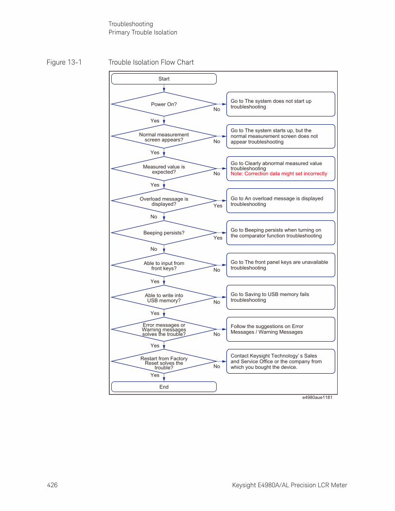
426 Keysight E4980A/AL Precision LCR Meter
TroubleshootingPrimary Trouble Isolation
13-
Figure 13-1 Trouble Isolation Flow Chart
Start
End
Restart from FactoryReset solves the
trouble?
Able to write intoUSB memory?
Able to input fromfront keys?
Beeping persists?
Overload message isdisplayed?
Measured value isexpected?
Normal measurementscreen appears?
Power On?
Error messages orWarning messagessolves the trouble?
Go to The system does not start uptroubleshooting
Go to The system starts up, but the normal measurement screen does not appear troubleshooting
Go to Clearly abnormal measured valuetroubleshootingNote: Correction data might set incorrectly
Go to An overload message is displayedtroubleshooting
Go to Beeping persists when turning on the comparator function troubleshooting
Go to The front panel keys are unavailable troubleshooting
Go to Saving to USB memory failstroubleshooting
Follow the suggestions on Error Messages / Warning Messages
Contact Keysight Technology’ s Sales and Service Office or the company from which you bought the device.
Yes
Yes
Yes
No
No
No
No
No
Yes
Yes
No
No
No
No
Yes
Yes
Yes
Yes
e4980aue1181
Keysight E4980A/AL Precision LCR Meter 427
TroubleshootingCheck Items When Trouble Occurs
Check Items When Trouble Occurs
The system does not start up (Nothing is displayed)
o Confirm that the power cable is properly plugged in.
o Confirm that the fuse is not blown.
If normal operation does not resume after taking the above measures, there is the possibility of a failure. Unplug the power cable immediately and contact Keysight Technologies’s Customer Contact, listed at the end of this guide, or the company from which you bought the device.
The system starts up, but the normal measurement screen does not appear (Service Mode)
The Service Mode is a state that occurs when the power-on test fails. Here, the characters on the display turn yellow and all of the front panel keys are unavailable.
o Confirm that the power-on test or a self test has failed.
When the power-on test at start-up fails, the error message “Power on test failed” is displayed in the system message area.
For details on the Service Mode, refer to the Service Guide.
o When the power is turned on with the interface board of the E4980A/AL rear panel removed, the E4980A/AL enters the service mode. In this case, reset the interface board and then turn the power on.
The E4980A/AL also enters the service mode when the interface board isn’t set properly.
When the normal measurement screen does not appear, there is the possibility of a failure. Contact Keysight Technologies’s Customer Contact, listed at the end of this guide, or the company from which you bought the device.
An overload message is displayed
An overload is often detected by the E4980A/AL when nothing is connected to the UNKNOWN terminal.
For conditions where overload occurs, refer to “Displaying Errors instead of Measurement Results” on page 71.
If the measurement/DCR/DCI ranges are set at Hold, enable the auto to select the optimum range. Then set the range at Hold. This may solve a overload.
Occasionally, there are missing pixels or constantly lit pixels, but this is not a malfunction and does not affect measurement results.
428 Keysight E4980A/AL Precision LCR Meter
TroubleshootingCheck Items When Trouble Occurs
13-
Beeping persists when turning on the comparator function
o Confirm that the limit range is set up properly.
When the beep is set up to sound when the comparator function is on, the beep sounds on every completion of measurement if the limit range is set up improperly.
The front panel keys are unavailable
o Check if the keys are locked.
When the keys are locked, LOCK is displayed in the status display area in the lower-right corner of the screen.
Press the [Local/Lock] key to unlock the keys.
o Check if the instrument is in the remote mode.
If the E4980A/AL is in the remote mode, RMT is displayed in the status display area in the lower-right corner of the screen.
Press the [Local/Lock] key to clear the remote mode.
Clearly abnormal measured value
o Measurement of compensation data may have failed.
Measure the compensation data again. For how to measure correction data, refer to“CORRECTION page” on page 112.
For example,
— setting up the OPEN state and SHORT state inversely.
— the OPEN/SHORT/LOAD is connected incompletely.
— previous correction data is used.
— after correction, different length cable/different fixture is connected or settings of frequency/level is changed.
For those cases, connect OPEN/SHORT/LOAD properly or fixture/cable properly and then perform the correction with new conditions.
o If the measured value is still abnormal even after taking the above measure, turn off the correction function.
When the E4980A/AL enters a local lockout state by sending the LOCAL LOCK BUS command from the controller, you cannot unlock the remote mode even if you press the [Local/Lock] key. (Only RMT is displayed in the status display area, so you cannot distinguish the local lockout state from a normal remote mode.)
Send the LOCAL BUS command from the controller to cancel this state, which enables control of the E4980A/AL on the front panel.
Keysight E4980A/AL Precision LCR Meter 429
TroubleshootingCheck Items When Trouble Occurs
Perform resistance measurement of 100 to 1 k DUT by using the E4980A/AL’s fixture after turning off OPEN/SHORT/LOAD on the CORRECTION page and setting cable length to zero. If a measured value close to the DUT’s value is displayed, there is the possibility of correction failure or inappropriate cable length.
For those cases, perform the correction with proper OPEN/SHORT/LOAD or with proper fixture/cable.
o When the MULTI compensation is ON, check that the channel and the definition method of the LOAD standard value are selected correctly.
Saving to USB memory fails
Some USB memory does not work on the E4980A/AL with firmware A.xx.xx. See the section on “USB interface port” in data sheet.
An error message or warning message is displayed
For information on error messages and warning messages, refer to “Error Messages” on page 435.
430 Keysight E4980A/AL Precision LCR Meter
TroubleshootingCheck Items When Trouble Occurs During Remote Control
13-
Check Items When Trouble Occurs During Remote Control
The instrument does not respond to the external controller or malfunctions
o Confirm that the connection setting is correct.
Check that the GPIB address for a GPIB connection or the IP address for a LAN connection is set up correctly on the SYSTEM CONFIG screen of the E4980A/AL or the connection setting screen of the external controller.
o Confirm that connection cables such as the GPIB cable, USB cable, and LAN cable are connected and in good condition.
o Check whether another instrument connected by the GPIB or LAN cable has the same GPIB address or IP address.
o Check that the GPIB cable is not looped.
You cannot read out the measured value.
o Confirm that the data transfer format is set up correctly.
An error message is displayed
o Check that the program is correct.
For details on error messages, refer to “Error Messages” on page 435.
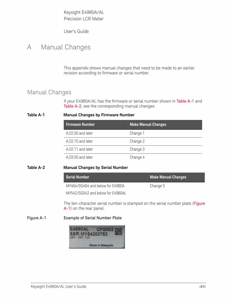
Keysight E4980A/AL User’s Guide -431
Keysight E4980A/ALPrecision LCR Meter
User’s Guide
A Manual Changes
This appendix shows manual changes that need to be made to an earlier revision according to firmware or serial number.
Manual ChangesIf your E4980A/AL has the firmware or serial number shown in Table A-1 and Table A-2, see the corresponding manual changes.
The ten-character serial number is stamped on the serial number plate (Figure A-1) on the rear panel.
Figure A-1 Example of Serial Number Plate
Table A-1 Manual Changes by Firmware Number
Firmware Number Make Manual Changes
A.02.00 and later Change 1
A.02.10 and later Change 2
A.02.11 and later Change 3
A.03.00 and later Change 4
Table A-2 Manual Changes by Serial Number
Serial Number Make Manual Changes
MY464/SG464 and below for E4980A
MY542/SG542 and below for E4980AL
Change 5
-432 Keysight E4980A/AL User’s Guide
Manual ChangesManual Changes
-
Change 5
The following function and SCPI commands are supported.
o Current Bias Interface is supported.
o :SYSTem:COMMunicate:LAN[:SELF]:RESTart command is available to restart the network.
o :SYSTem:RESTart command is available to reboot the instrument immediately.
Change 4
The following options are newly added to the firmware revision A.03.00.
o Option 030, 050, 100 and 200
Change 3
The following functions are newly added to the firmware revision A.02.11.
o Change the resolution to 20mA from 1A to 2A of the DC bias signal current level at the connection of two 42841A devices.
Change 2
The following functions are newly added to the firmware revision A.02.10.
o Command to set the DC bias range has been added.
The firmware revision A.02.00 and below does not support the following SCPI command. Please delete the descriptions about this command from this manual.
— “:BIAS:RANGe:AUTO” on page 327
Change 1
The following functions are newly added to the firmware revision A.02.00.
o New softkey which has LAN reset function.
o Compliant with LXI (Lan eXtensions for Instrumentation) standard Class C
o DHCP ON/OFF function and AUTO IP address ON/OFF function integrated (IP CONFIG field).
o “Status” which displays the LAN connection status changed (CURRENT LAN STATUS monitor).
Keysight E4980A/AL User’s Guide -433
Manual ChangesManual Changes
For “Status” of the firmware revision A.02.00 or lower, which displays the LAN connection status, refer to the following table.
The firmware revision A.01.0x does not support the following SCPI command. Please delete the descriptions about this command from this manual.
— “:SYSTem:COMMunicate:LAN[:SELF]:CONFigure” on page 372
The firmware revision A.02.00 or later does not support the following SCPI commands.
— “:SYSTem:COMMunicate:LAN[:SELF]:AIP[:STATe]” on page 371
— “:SYSTem:COMMunicate:LAN[:SELF]:DHCP[:STATe]” on page 373
Status Description
OK LAN connection is OK
DISCONNECTED Disconnected from the LAN
INITIALIZING LAN connection is being initialized
FAILED LAN connection has failed.

-434 Keysight E4980A/AL User’s Guide
Manual ChangesManual Changes
-
Keysight E4980A/AL User’s Guide -435
Keysight E4980A/ALPrecision LCR Meter
User’s Guide
B Error Messages
The Keysight E4980A/AL provides error messages to indicate its operating status. This appendix describes the error messages of the E4980A/AL in numeric order.
Error MessagesAn error message is displayed in the instrument status display area in the lower-left part of the screen. Pressing any of the front keys other than the [Local/Lock] key or executing the :DISP:CCL command clears the error message. Moreover, when a sweep is started again, the display of a particular error message may disappear. Errors caused by operation of a front panel key simply appear on the display; with a few exceptions, these are not stored in the error queue.
In the log of an error message, a maximum 100 pieces are recorded, and it is possible to go back and check from the oldest error. Executing the :SYST:ERR? command checks error logs. This operation can be performed only by the “SCPI” command. It cannot be operated from the front panel.
An error with a positive error number is one uniquely defined for this instrument. On the other hand, an error with a negative error number is basically one defined for common GPIB devices in IEEE488.2.
When the error code is displayed on the screen of the instrument, there will be a letter “E” with error code and error description are displayed.
E1103 A1 EEPROM write error
Error Messages Category
— -440 to -100: GPIB devices in IEEE488.2
— 10 to 90: Setup
— 1000 to 1201: Hardware
-436 Keysight E4980A/AL User’s Guide
Error MessagesError Messages
-
GPIB devices in IEEE488.2
-440 Query UNTERMINATED error after indefinite response
A query that requests arbitrary data response (*IDN? and *OPT? queries) is sent before normal queries in a program message (for example, FREQ?;*IDN? is expected, but *IDN?;FREQ? is received).
-430 Query DEADLOCKED
Input buffer and output buffer are full; cannot continue.
-420 Query UNTERMINATED
Addressed to talk, incomplete program message received.
-410 Query INTERRUPTED
Query is followed by DAB or GET before the response is completed.
-400 Query error
Query is improper.
-350 Queue overflow
There is no room in the queue and an error occurred but was not recorded.
Suggestion:
Clear the error queue.
-250 Mass storage error
An error occurred while accessing the USB memory. A USB memory-related error other than -257 error (File Name Error) occurred.
-230 Data corrupt or stale
The setting file or correction data to be read cannot be read out with the current firmware version because the setting file or correction data is corrupt or old.
-224 Illegal parameter value
The parameter value is not properly set. This error occurs, for example, when the :FUNC:IMP command is used to specify an Impedance-parameter that does not exist (as CPRS).
-223 Too many digits
The received numeric value is too long (exceeds 255 digits).
-223 Too much data
The block-, expression-, or character-string-type program data that are received conform with the standard but exceed the amount that can be processed under the condition of the memory or conditions specific to memory-related devices. In this instrument, this error occurs when the number of characters exceeds 254 in a character-string parameter.
Keysight E4980A/AL User’s Guide -437
Error MessagesError Messages
-222 Data out of range
A data element (not violating the standard) outside the range defined by this instrument has been received. This error occurs, for example, when an integer-based command for which the parameter can be rounded exceeds the range of -2147483648 to +2147483647 or when a real-number-based command for which the parameter can be rounded exceeds the range of -9.9e37 to +9.9e37. This error also occurs when a numeric value other than a specified one is entered into a command in which the “BIN number” and “list table number” are specified as parameters and thus the parameters are not rounded.
-220 Parameter error
When a parameter-related error other than Errors -221 through -229 occur, this error message is displayed.
-211 Trigger ignored
The instrument receives and detects a trigger command (“:TRIG”) or an external trigger signal, but it is ignored due to the timing condition (the instrument is not in the wait-for- trigger state, for example).
Suggestion:
Change the setup so that a trigger command or an external trigger signal can be sent after the instrument has entered the wait-for- trigger state.
-200 Execution error
An error associated with execution has been generated for which this instrument cannot specify the error message. This code indicates that an error associated with execution defined in 11.5.1.1.5, IEEE488.2 has occurred.
-178 Expression data not allowed
Expression data is not allowed.
-171 Invalid expression
Invalid expression was received (for example, illegal character in expression).
-170 Expression error
Expression is improper.
-168 Block data not allowed
Block data is not allowed.
-161 Invalid block data
Invalid block data was received (for example, END received before length satisfied).
-160 Block data error
Block data is improper.

-438 Keysight E4980A/AL User’s Guide
Error MessagesError Messages
-
-158 String data not allowed
String data is not allowed.
-151 Invalid string data
Invalid string data was received (for example, END received before close quote).
-150 String data error
String data is improper.
-148 Character data not allowed
Character data not allowed for this operation.
-144 Character data too long
Character data is too long (maximum length is 12 characters).
-141 Invalid character data
Bad character data or unrecognized character data was received.
-140 Character data error
Character data is improper.
-138 Suffix not allowed
A suffix is not allowed for this operation.
-131 Invalid suffix
Units are unrecognized, or the units are not appropriate.
-128 Numeric data error
Numeric data is improper.
-128 Numeric data not allowed
Numeric data not allowed for this operation.
-123 Exponent too long
The magnitude of the exponent was larger than 32000.
-121 Invalid character in number
Invalid character in numeric data.
-114 Header Suffix out of Range
The header suffix is out of range.
-113 Undefined header
A command not defined in this instrument, though not illegal in the syntactic structure, has been received. For example, when the message “:OUTP:DC:ISOL:FREQ:AUTO ON” is sent instead of the correct program
Keysight E4980A/AL User’s Guide -439
Error MessagesError Messages
message “:OUTP:DC:ISOL:LEV:AUTO ON” the message sent is received as an undefined command by this instrument. See the command reference and use the correct command.
-112 Program mnemonic too long
Program mnemonic is too long (maximum length is 12 characters).
-109 Missing parameter
The number of parameters is less than that required for the command, or the parameter has not been entered. For example, the command “:CORR:USE” requires one more parameter. Therefore, when a message “:CORR:USE” is sent to a correct program message “:CORR:USE 11,” this instrument receives the former message as an invalid one because all parameters have not been entered.
Suggestion:
Enter command parameters correctly.
-108 Parameter not allowed
The number of parameters exceeds that required for the command. For instance, when a program message “:FORM:BORD NORM, ASC” is sent instead of a correct program message with a command “:FORM:BORD NORM”, which requires a parameter, the instrument receives the message that the number of parameters is invalid.
Suggestion:
See the command reference to confirm the required number of parameters.
-105 GET not allowed
GET is not allowed inside a program message.
-104 Data type error
Improper data type used (for example, string data was expected, but numeric data was received).
-103 Invalid separator
The message unit separator (for example, “;”, “,”) is improper.
-102 Syntax error
Unrecognized command or data type was received.
-101 Invalid character
Invalid character was received.
-100 Command Error
Improper command.
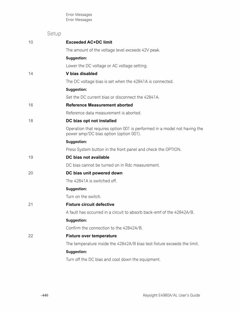
-440 Keysight E4980A/AL User’s Guide
Error MessagesError Messages
-
Setup
10 Exceeded AC+DC limit
The amount of the voltage level exceeds 42V peak.
Suggestion:
Lower the DC voltage or AC voltage setting.
14 V bias disabled
The DC voltage bias is set when the 42841A is connected.
Suggestion:
Set the DC current bias or disconnect the 42841A.
16 Reference Measurement aborted
Reference data measurement is aborted.
18 DC bias opt not installed
Operation that requires option 001 is performed in a model not having the power amp/DC bias option (option 001).
Suggestion:
Press System button in the front panel and check the OPTION.
19 DC bias not available
DC bias cannot be turned on in Rdc measurement.
20 DC bias unit powered down
The 42841A is switched off.
Suggestion:
Turn on the switch.
21 Fixture circuit defective
A fault has occurred in a circuit to absorb back-emf of the 42842A/B.
Suggestion:
Confirm the connection to the 42842A/B.
22 Fixture over temperature
The temperature inside the 42842A/B bias test fixture exceeds the limit.
Suggestion:
Turn off the DC bias and cool down the equipment.
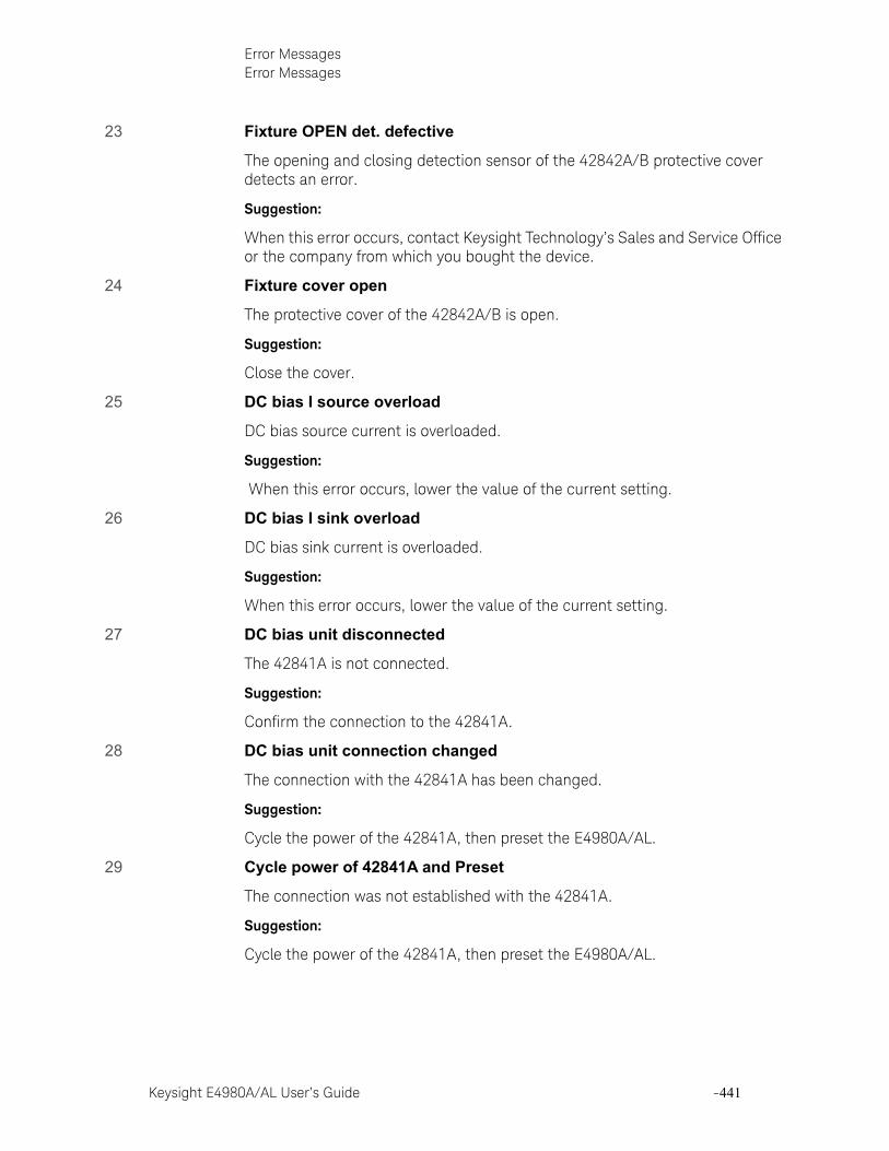
Keysight E4980A/AL User’s Guide -441
Error MessagesError Messages
23 Fixture OPEN det. defective
The opening and closing detection sensor of the 42842A/B protective cover detects an error.
Suggestion:
When this error occurs, contact Keysight Technology’s Sales and Service Office or the company from which you bought the device.
24 Fixture cover open
The protective cover of the 42842A/B is open.
Suggestion:
Close the cover.
25 DC bias I source overload
DC bias source current is overloaded.
Suggestion:
When this error occurs, lower the value of the current setting.
26 DC bias I sink overload
DC bias sink current is overloaded.
Suggestion:
When this error occurs, lower the value of the current setting.
27 DC bias unit disconnected
The 42841A is not connected.
Suggestion:
Confirm the connection to the 42841A.
28 DC bias unit connection changed
The connection with the 42841A has been changed.
Suggestion:
Cycle the power of the 42841A, then preset the E4980A/AL.
29 Cycle power of 42841A and Preset
The connection was not established with the 42841A.
Suggestion:
Cycle the power of the 42841A, then preset the E4980A/AL.
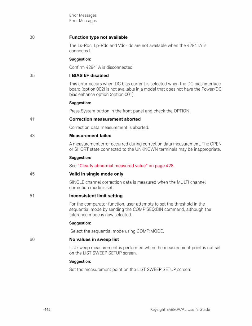
-442 Keysight E4980A/AL User’s Guide
Error MessagesError Messages
-
30 Function type not available
The Ls-Rdc, Lp-Rdc and Vdc-Idc are not available when the 42841A is connected.
Suggestion:
Confirm 42841A is disconnected.
35 I BIAS I/F disabled
This error occurs when DC bias current is selected when the DC bias interface board (option 002) is not available in a model that does not have the Power/DC bias enhance option (option 001).
Suggestion:
Press System button in the front panel and check the OPTION.
41 Correction measurement aborted
Correction data measurement is aborted.
43 Measurement failed
A measurement error occurred during correction data measurement. The OPEN or SHORT state connected to the UNKNOWN terminals may be inappropriate.
Suggestion:
See “Clearly abnormal measured value” on page 428.
45 Valid in single mode only
SINGLE channel correction data is measured when the MULTI channel correction mode is set.
51 Inconsistent limit setting
For the comparator function, user attempts to set the threshold in the sequential mode by sending the COMP:SEQ:BIN command, although the tolerance mode is now selected.
Suggestion:
Select the sequential mode using COMP:MODE.
60 No values in sweep list
List sweep measurement is performed when the measurement point is not set on the LIST SWEEP SETUP screen.
Suggestion:
Set the measurement point on the LIST SWEEP SETUP screen.

Keysight E4980A/AL User’s Guide -443
Error MessagesError Messages
62 Bias off, Turn bias on
DC bias sweep is performed with the DC BIAS function OFF.
Suggestion:
Set the DC BIAS function to ON.
63 DC source off, Turn DC source on
DC source sweep is performed with the DC source function OFF.
Suggestion:
Set the DC source function to ON.
70 Handler I/F not installed
The handler interface function is set to ON in a model that does not have a handler interface board (option 201).
Suggestion:
Press System button in the front panel and check the OPTION.
71 Scanner I/F not installed
Operation that requires option 301 is performed in a model that does not have a scanner interface board (option 301).
Suggestion:
Press System button in the front panel and check the OPTION.
73 I BIAS I/F not installed
The DC bias interface function is set to ON in a model that does not have the DC bias interface board (option 002).
Suggestion:
Press System button in the front panel and check the OPTION.
82 Store failed
User attempts to save data into the USB memory when a USB memory device is not inserted. This error may appear when you attempt to save data immediately after inserting the USB memory into the E4980A/AL. You need to wait for a few seconds after inserting the USB.
Suggestion:
Prepare the USB memory device or save data into number 0 to 9.
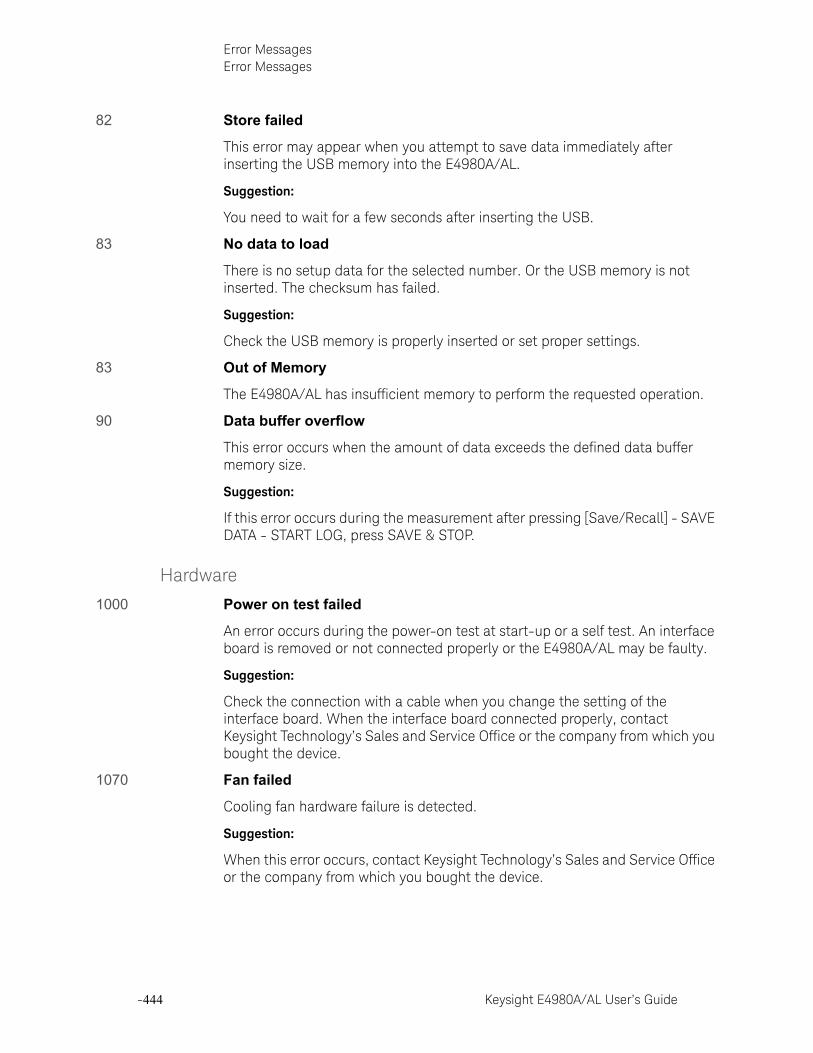
-444 Keysight E4980A/AL User’s Guide
Error MessagesError Messages
-
82 Store failed
This error may appear when you attempt to save data immediately after inserting the USB memory into the E4980A/AL.
Suggestion:
You need to wait for a few seconds after inserting the USB.
83 No data to load
There is no setup data for the selected number. Or the USB memory is not inserted. The checksum has failed.
Suggestion:
Check the USB memory is properly inserted or set proper settings.
83 Out of Memory
The E4980A/AL has insufficient memory to perform the requested operation.
90 Data buffer overflow
This error occurs when the amount of data exceeds the defined data buffer memory size.
Suggestion:
If this error occurs during the measurement after pressing [Save/Recall] - SAVE DATA - START LOG, press SAVE & STOP.
Hardware
1000 Power on test failed
An error occurs during the power-on test at start-up or a self test. An interface board is removed or not connected properly or the E4980A/AL may be faulty.
Suggestion:
Check the connection with a cable when you change the setting of the interface board. When the interface board connected properly, contact Keysight Technology’s Sales and Service Office or the company from which you bought the device.
1070 Fan failed
Cooling fan hardware failure is detected.
Suggestion:
When this error occurs, contact Keysight Technology’s Sales and Service Office or the company from which you bought the device.
Keysight E4980A/AL User’s Guide -445
Error MessagesError Messages
1080 Power failed
Power unit hardware failure is detected.
Suggestion:
When this error occurs, contact Keysight Technology’s Sales and Service Office or the company from which you bought the device.
1103 A1 EEPROM write error
An error is generated while writing data to A1 EEPROM.
Suggestion:
When this error occurs, contact Keysight Technology’s Sales and Service Office or the company from which you bought the device.
1200 CPU Bd FLASH ROM write error
An error is generated while writing data to FLASH.
Suggestion:
When this error occurs, contact Keysight Technology’s Sales and Service Office or the company from which you bought the device.
1201 CPU Bd EEPROM write error
An error is generated while writing data to EEPROM.
Suggestion:
When this error occurs, contact Keysight Technology’s Sales and Service Office or the company from which you bought the device.
-446 Keysight E4980A/AL User’s Guide
Error MessagesWarning Messages
-
Warning MessagesA warning message is displayed in the instrument status display area in the lower-left part of the display. Pressing any of the front keys other than the [Local/Lock] key or executing the :DISP:CCL command clears the message.
This message simply appears on the display since it is not known to remote environments such as GPIB. This message is not displayed when another error message is already displayed in the instrument message/warning area.
The warning messages for this instrument are as follows.
Numeric
1 I bias unit
The E4980A finds one current bias unit (42841A) connected.
2 I bias units
The E4980A/AL finds two current bias units (42841A) connected.
A
ALC unable to regulate
The voltage level setting is inappropriate for using the ALC function. The ALC function does not work and the operation will be the same as when the ALC function is turned off. The measurement data status is set to 4.
Suggestions:
Turn off ALC. For more details, refer to “Automatic level control” on page 93.
C
Can't change while DCI Isolation OFF
This message appears when the DCI measurement range (DCI RND) is changed when the bias current isolation function is OFF.
Suggestions:
Turn on the Bias current isolation function.
Can't change while 2nd sweep param exists
This message appears when attempting to change or delete the list sweep parameter from the E4980A/AL’s screen after setting the sweep point for the second parameter with the GPIB command.
Suggestions:
Use the GPIB command to change the list sweep parameter.
Keysight E4980A/AL User’s Guide -447
Error MessagesWarning Messages
Clear the table first
This error occurs when the value of MODE has been changed when the LIMIT TABLE SETUP screen is moved to another screen or the sweep parameter on the LIST SWEEP SETUP screen is changed even though a sweep list for another measurement parameter exists.
Suggestions:
Clear the table first and then change the Limit mode.
Correction, not effective
The correction function does not work because the MULTI correction mode is used but the test frequency is not equal to the spot frequency.
I
Improper high/low limits
The upper limit value is less than the lower limit value. Or the lower limit value is larger than the upper limit value.
Suggestions:
Set the lower limit value to less than the upper limit value. Or set the upper limit value to larger than the lower limit value.
Incompatible state file
The setting file recalled from a USB memory device has been saved using an E4980A/AL with a different firmware version or different options. There may be some parameters set up incorrectly. This message may appear when the connection status of the 42841A is different from the one when it has been saved.
Suggestions:
Check the firmware revision and options of the setting file.
S
Signal source overload
The test signal current exceeds a value shown in Table 11-6. The measurement data is not guaranteed to be valid. The measurement result data status of the measurement result output is set to 3.
Suggestions:
Reduce the test signal level so that the test signal current doesn’t exceed a value shown in Table 11-6.

-448 Keysight E4980A/AL User’s Guide
Error MessagesWarning Messages
-
Signal source overvoltage
The signal source voltage exceeds its limit.
Suggestions:
Lower the voltage setting of the signal source.
Keysight E4980A/AL User’s Guide -449
Keysight E4980A/ALPrecision LCR Meter
User’s Guide
C List of Default Values
This appendix gives the default values, settings for Save/Recall of an object, and settings for backing up an object when using the Keysight E4980A/AL.
-450 Keysight E4980A/AL User’s Guide
List of Default ValuesList of Default Values, Save/Recall Settings, and Backup Settings
-
List of Default Values, Save/Recall Settings, and Backup SettingsThe table below shows the following settings for the Keysight E4980A/AL. For the factory default settings of the LAN, refer to “List of LAN Factory Default Settings” on page 455.
— Factory-shipped settings (when you press [Preset] - FACTORY DEFAULT)All data that the user can set are cleared. The system date and time, however, are not cleared.
— Preset settings (the status when you press [Preset] - CLEAR SET & CORR key or execute the :SYST:PRES command)Calibration data and items that are backed up in the List of Default Values are cleared.
— *RST Settings (the status when you press [Preset] - CLEAR SETTING key or execute the *RST command)Basic setting parameters which can be set from the front panel or the SCPI commands are cleared.
— Settings that permit Save/Recall of a setup state
In the table, states that can be saved/recalled are denoted in the following manner:
* : Save/Recall can be performed
Blank: Save/Recall cannot be performed
— Settings that are backed up (set state not affected by turning power ON/OFF)
In the table, a setting that is automatically backed up is denoted in the following manner:
* : Backup operation performed
Blank: Backup operation not performed
— Available means of defining a setting
In the table, the following symbols are used to denote the method(s) that can be used to define a setting.
K: Using the front panel key
C: Using the SCPI command
In the table, the “<<” symbol shows that the setup is the same as that in the box to the left.
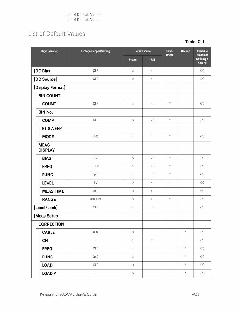
Keysight E4980A/AL User’s Guide -451
List of Default ValuesList of Default Values
List of Default ValuesTable C-1
Key Operation Factory-shipped Setting Default Value Save/Recall
Backup Available Means of Defining a
SettingPreset *RST
[DC Bias] OFF << << K/C
[DC Source] OFF << << K/C
[Display Format]
BIN COUNT
COUNT OFF << << * K/C
BIN No.
COMP OFF << << * K/C
LIST SWEEP
MODE SEQ << << * K/C
MEAS DISPLAY
BIAS 0 V << << * K/C
FREQ 1 kHz << << * K/C
FUNC Cp-D << << * K/C
LEVEL 1 V << << * K/C
MEAS TIME MED << << * K/C
RANGE AUTO(ON) << << * K/C
[Local/Lock] OFF << << K/C
[Meas Setup]
CORRECTION
CABLE 0 m << * K/C
CH 0 << << K/C
FREQ OFF << * K/C
FUNC Cp-D << * K/C
LOAD OFF << * K/C
LOAD A --- << * K/C
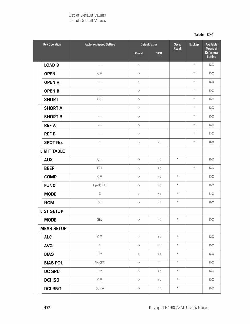
-452 Keysight E4980A/AL User’s Guide
List of Default ValuesList of Default Values
-
LOAD B --- << * K/C
OPEN OFF << * K/C
OPEN A --- << * K/C
OPEN B --- << * K/C
SHORT OFF << * K/C
SHORT A --- << * K/C
SHORT B --- << * K/C
REF A --- << * K/C
REF B --- << * K/C
SPOT No. 1 << << * K/C
LIMIT TABLE
AUX OFF << << * K/C
BEEP FAIL << << * K/C
COMP OFF << << * K/C
FUNC Cp-D(OFF) << << * K/C
MODE % << << * K/C
NOM 0 F << << * K/C
LIST SETUP
MODE SEQ << << * K/C
MEAS SETUP
ALC OFF << << * K/C
AVG 1 << << * K/C
BIAS 0 V << << * K/C
BIAS POL FIX(OFF) << << * K/C
DC SRC 0 V << << * K/C
DCI ISO OFF << << * K/C
DCI RNG 20 mA << << * K/C
Table C-1
Key Operation Factory-shipped Setting Default Value Save/Recall
Backup Available Means of Defining a
SettingPreset *RST
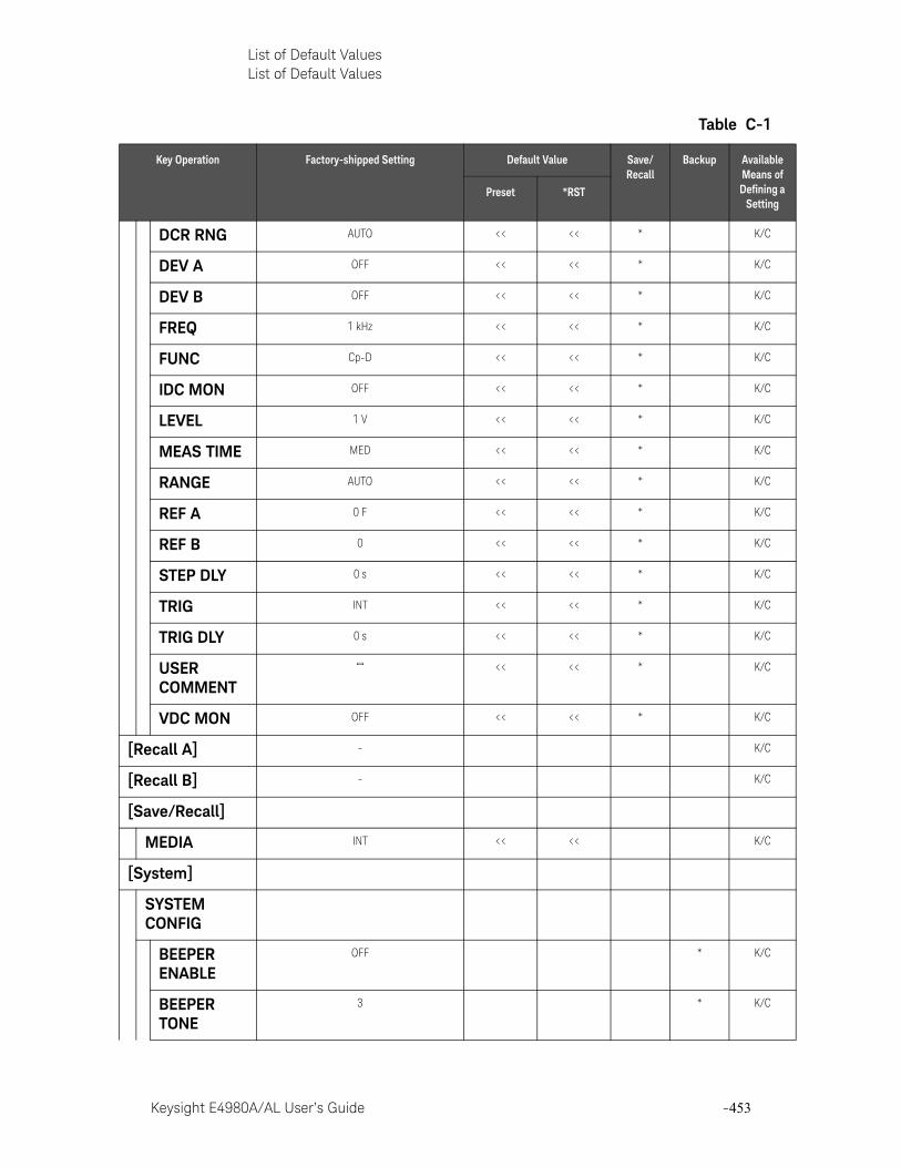
Keysight E4980A/AL User’s Guide -453
List of Default ValuesList of Default Values
DCR RNG AUTO << << * K/C
DEV A OFF << << * K/C
DEV B OFF << << * K/C
FREQ 1 kHz << << * K/C
FUNC Cp-D << << * K/C
IDC MON OFF << << * K/C
LEVEL 1 V << << * K/C
MEAS TIME MED << << * K/C
RANGE AUTO << << * K/C
REF A 0 F << << * K/C
REF B 0 << << * K/C
STEP DLY 0 s << << * K/C
TRIG INT << << * K/C
TRIG DLY 0 s << << * K/C
USER COMMENT
““ << << * K/C
VDC MON OFF << << * K/C
[Recall A] - K/C
[Recall B] - K/C
[Save/Recall]
MEDIA INT << << K/C
[System]
SYSTEM CONFIG
BEEPER ENABLE
OFF * K/C
BEEPER TONE
3 * K/C
Table C-1
Key Operation Factory-shipped Setting Default Value Save/Recall
Backup Available Means of Defining a
SettingPreset *RST
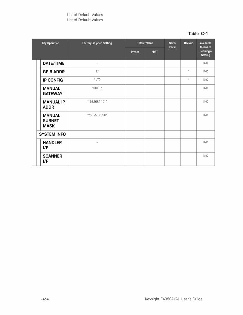
-454 Keysight E4980A/AL User’s Guide
List of Default ValuesList of Default Values
-
DATE/TIME - K/C
GPIB ADDR 17 * K/C
IP CONFIG AUTO * K/C
MANUAL GATEWAY
“0.0.0.0” K/C
MANUAL IP ADDR
“192.168.1.101” K/C
MANUAL SUBNET MASK
“255.255.255.0” K/C
SYSTEM INFO
HANDLER I/F
- K/C
SCANNER I/F
- K/C
Table C-1
Key Operation Factory-shipped Setting Default Value Save/Recall
Backup Available Means of Defining a
SettingPreset *RST
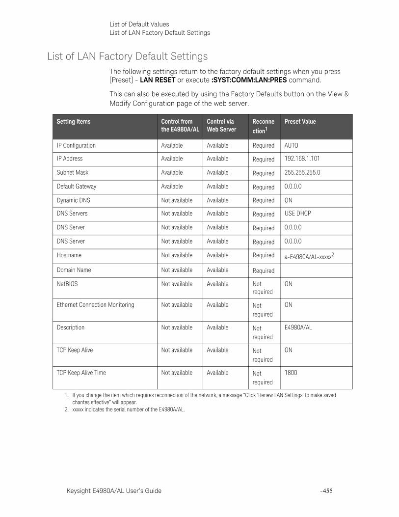
Keysight E4980A/AL User’s Guide -455
List of Default ValuesList of LAN Factory Default Settings
List of LAN Factory Default SettingsThe following settings return to the factory default settings when you press [Preset] - LAN RESET or execute :SYST:COMM:LAN:PRES command.
This can also be executed by using the Factory Defaults button on the View & Modify Configuration page of the web server.
Setting Items Control from the E4980A/AL
Control via Web Server
Reconnection1
Preset Value
IP Configuration Available Available Required AUTO
IP Address Available Available Required 192.168.1.101
Subnet Mask Available Available Required 255.255.255.0
Default Gateway Available Available Required 0.0.0.0
Dynamic DNS Not available Available Required ON
DNS Servers Not available Available Required USE DHCP
DNS Server Not available Available Required 0.0.0.0
DNS Server Not available Available Required 0.0.0.0
Hostname Not available Available Required a-E4980A/AL-xxxxx2
Domain Name Not available Available Required
NetBIOS Not available Available Not required
ON
Ethernet Connection Monitoring Not available Available Not required
ON
Description Not available Available Not required
E4980A/AL
TCP Keep Alive Not available Available Not required
ON
TCP Keep Alive Time Not available Available Not required
1800
1. If you change the item which requires reconnection of the network, a message “Click ‘Renew LAN Settings’ to make saved chantes effective” will appear.
2. xxxxx indicates the serial number of the E4980A/AL.

-456 Keysight E4980A/AL User’s Guide
List of Default ValuesList of LAN Factory Default Settings
-
Keysight E4980A/AL User’s Guide -457
Keysight E4980A/ALPrecision LCR Meter
User’s Guide
D Bias Current Interface
This chapter explains how to use Option 002 Bias Current Interface, which adds a digital interface to allow the E4980A to control the Keysight E4980A Precision LCR Meter’s bias current source.
This information is only for serial prefix number below: MY464/SG464 and below for E4980A
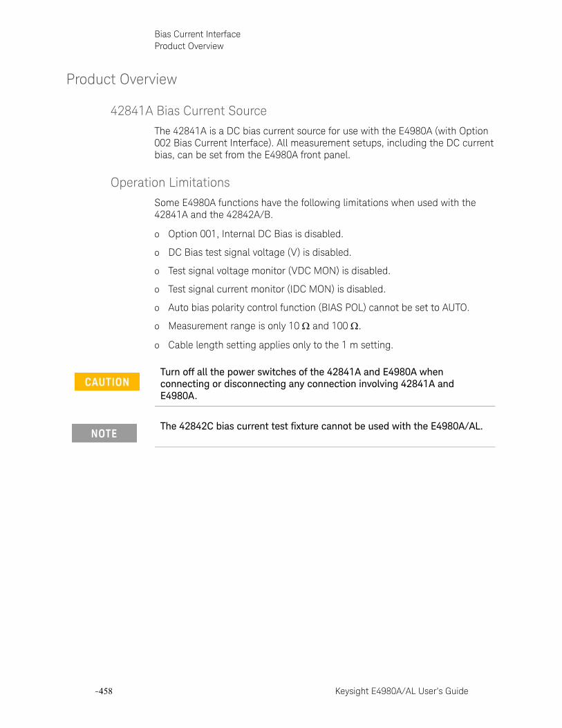
-458 Keysight E4980A/AL User’s Guide
Bias Current InterfaceProduct Overview
-
Product Overview
42841A Bias Current Source
The 42841A is a DC bias current source for use with the E4980A (with Option 002 Bias Current Interface). All measurement setups, including the DC current bias, can be set from the E4980A front panel.
Operation Limitations
Some E4980A functions have the following limitations when used with the 42841A and the 42842A/B.
o Option 001, Internal DC Bias is disabled.
o DC Bias test signal voltage (V) is disabled.
o Test signal voltage monitor (VDC MON) is disabled.
o Test signal current monitor (IDC MON) is disabled.
o Auto bias polarity control function (BIAS POL) cannot be set to AUTO.
o Measurement range is only 10 and 100 .
o Cable length setting applies only to the 1 m setting.
Turn off all the power switches of the 42841A and E4980A when connecting or disconnecting any connection involving 42841A and E4980A.
The 42842C bias current test fixture cannot be used with the E4980A/AL.
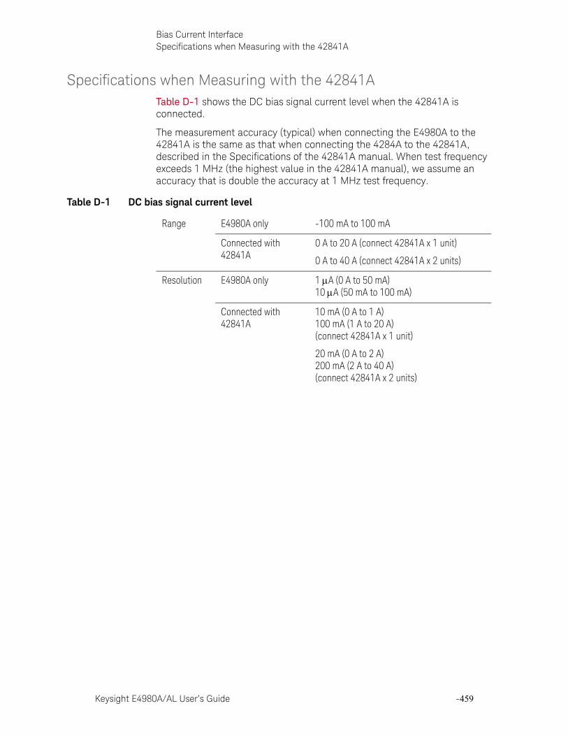
Keysight E4980A/AL User’s Guide -459
Bias Current InterfaceSpecifications when Measuring with the 42841A
Specifications when Measuring with the 42841ATable D-1 shows the DC bias signal current level when the 42841A is connected.
The measurement accuracy (typical) when connecting the E4980A to the 42841A is the same as that when connecting the 4284A to the 42841A, described in the Specifications of the 42841A manual. When test frequency exceeds 1 MHz (the highest value in the 42841A manual), we assume an accuracy that is double the accuracy at 1 MHz test frequency.
Table D-1 DC bias signal current level
Range E4980A only -100 mA to 100 mA
Connected with 42841A
0 A to 20 A (connect 42841A x 1 unit)
0 A to 40 A (connect 42841A x 2 units)
Resolution E4980A only 1 A (0 A to 50 mA)10 A (50 mA to 100 mA)
Connected with 42841A
10 mA (0 A to 1 A)100 mA (1 A to 20 A)(connect 42841A x 1 unit)
20 mA (0 A to 2 A)200 mA (2 A to 40 A)(connect 42841A x 2 units)
-460 Keysight E4980A/AL User’s Guide
Bias Current InterfacePreparation
-
Preparation
Equipment Requirements
The 42841A supplies 20 A (1 unit) and 40 A (2 units) DC current bias when combining the E4980A (test frequency: 20 Hz to 2 MHz) and the 42842A/B test fixture.
The following equipment is necessary for a system that uses the E4980A and the bias current source.
— E4980A Precision LCR Meter (with Option 002 Bias Current Interface)
— 42841A Bias Current Source (two units are necessary for 40 A system)
— 42842B Bias Current Test Fixture (only 42842B for 40 A system)
— 16048A Test Lead (with BNC connector)
— Bias Current Interface Cable (furnished with the 42841A)
— 42843A Bias Current Cable (required only for 40 A system)
Cable Connection
Each instrument needs to be connected using the bias current interface cable, 16048A test lead, and 42843A bias current cable (only for 40 A system). The cable connection varies depending on the system configuration.
20A System
Connect the E4980A to the 42841A and 42842A as shown in Figure D-1 on page 461 using the following procedure.
1. Connect the UNKNOWN terminal of the E4980A to the TO UNKNOWN terminal of the 42842A using the 16048A test lead.
2. Connect the Bias Current Interface connector of the E4980A to the Bias Current Control Input A connector of the 42841A using the cable and the adapter. The cable is furnished with the 42841A and the adapter is furnished with the E4980A.
3. Connect the 42842A test fixture directly to the front panel of the 42841A.
Confirm that Option 002 Bias Current Interface is installed in the option slot of the E4980A’s rear panel. When option 002 is installed, the 50-pin connector marked “Option 002: Bias Current Interface” is attached to either of the two option slots of the rear panel.
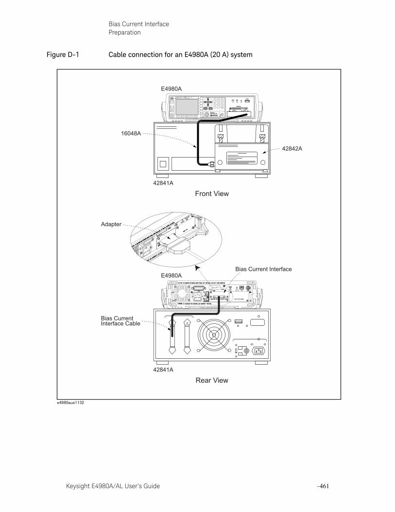
Keysight E4980A/AL User’s Guide -461
Bias Current InterfacePreparation
Figure D-1 Cable connection for an E4980A (20 A) system
USB
TriggerGPIB
Serial Label
LAN
LINE 115V -230V 50/60Hz150VA MAX
FuseT3A , 250V
E4980A
Option 710: No Interface
Rear View
Front View
E4980A
42841A
E4980A
42841A
16048A
42842A
Bias Current Interface
Bias CurrentInterface Cable
Adapter
E4980APrecision LCR Meter
20 Hz - 2 MHz
LCUR LPOT HPOT HCUR
DCBias USB
DCSource
UNKNOWN
Discharge test device before connecting42V Peak Max Output CAT I
10VDC Max
DC Source(Option 001/101)
Trigger
DC Bias
DCSource
Return
7 8 9
4 5 6
1 2 3
0 .
Preset
DisplayFormat
MeasSetup
Recall A Recall B Save/Recall System Local/
Lock
-462 Keysight E4980A/AL User’s Guide
Bias Current InterfacePreparation
-
40 A System
Connect the E4980A to the 42841A and the 42842B as shown in Figure D-2 on page 463 using the following procedure.
1. Connect the UNKNOWN terminal of the E4980A to the TO UNKNOWN terminal of the 42842B using the 16048A test lead.
2. Connect the 42842B test fixture directly to the front panel of the 42841A.
3. Connect the DC Bias Current Output Connector of the 42841A (that is not connected to the 42842B and DC Bias Current Input Connector of the 42842B side panel) using a 42843A Bias Current Cable.
4. Connect the E4980A Bias Current Interface connector to the Bias Current Control Input A connector of the 42841A using the furnished Bias Current Interface Cable (1) and the adapter. The cable is furnished with the 42841A and the adapter is furnished with the E4980A.
5. Connect the 42841A Bias Current Control Input B connector connected to the 42842B to the Bias Current Control Input A connector of the other 42841A using the furnished Bias Current Interface Cable (2).

Keysight E4980A/AL User’s Guide -463
Bias Current InterfacePreparation
Figure D-2 Cable connection for an E4980A(40 A) system
USB
TriggerGPIB
Serial Label
LAN
LINE 115V -230V 50/60Hz150VA MAX
FuseT3A , 250V
E4980A
Option 710: No Interface
Rear View
Front View
E4980A
42841A
42841A
42841A
E4980A
42841A
16048A
42842B
Bias Current Interface
Bias Current Interface Cable (1)
42843A
Bias Current Interface Cable (2)
Adapter
E4980APrecision LCR Meter
20 Hz - 2 MHz
LCUR LPOT HPOT HCUR
DCBias USB
DCSource
UNKNOWN
Discharge test device before connecting42V Peak Max Output CAT I
10VDC Max
DC Source(Option 001/101)
Trigger
DC Bias
DCSource
Return
7 8 9
4 5 6
1 2 3
0 .
Preset
DisplayFormat
MeasSetup
Recall A Recall B Save/Recall System Local/
Lock

-464 Keysight E4980A/AL User’s Guide
Bias Current InterfaceMeasurement Procedures
-
Measurement ProceduresFor measurement procedures when using the 42841A Bias Current Source, see “Basic Measurement Procedure” of the Chapter, “Operation Procedure and Examples” in the 42841A manual. The measurement procedure is the same as that of the 4284A.
Keysight E4980A/AL User’s Guide -465
Keysight E4980A/ALPrecision LCR Meter
User’s Guide
E Handler Interface
This chapter provides information necessary to use Option 201 Handler Interface for the Keysight E4980A/AL Precision LCR Meter.
OverviewThe Keysight E4980A/AL Option 201 Handler Interface outputs signals that indicate the end of a measurement cycle, the result of bin sorting by the comparator, and the result of Go/No-Go test by the list sweep comparator. In addition, the instrument accepts input of external trigger and key-lock signals. You can use these signals to easily integrate the E4980A/AL with a component handler or system controller. This means that you can fully automate such tasks as component inspection, component sorting, and processing of quality management data for higher manufacturing efficiency.
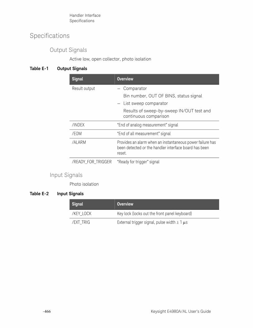
-466 Keysight E4980A/AL User’s Guide
Handler InterfaceSpecifications
-
Specifications
Output Signals
Active low, open collector, photo isolation
Input Signals
Photo isolation
Table E-1 Output Signals
Signal Overview
Result output — Comparator
Bin number, OUT OF BINS, status signal
— List sweep comparator
Results of sweep-by-sweep IN/OUT test and continuous comparison
/INDEX “End of analog measurement” signal
/EOM “End of all measurement” signal
/ALARM Provides an alarm when an instantaneous power failure has been detected or the handler interface board has been reset.
/READY_FOR_TRIGGER “Ready for trigger” signal
Table E-2 Input Signals
Signal Overview
/KEY_LOCK Key lock (locks out the front panel keyboard)
/EXT_TRIG External trigger signal, pulse width ≥ 1 s
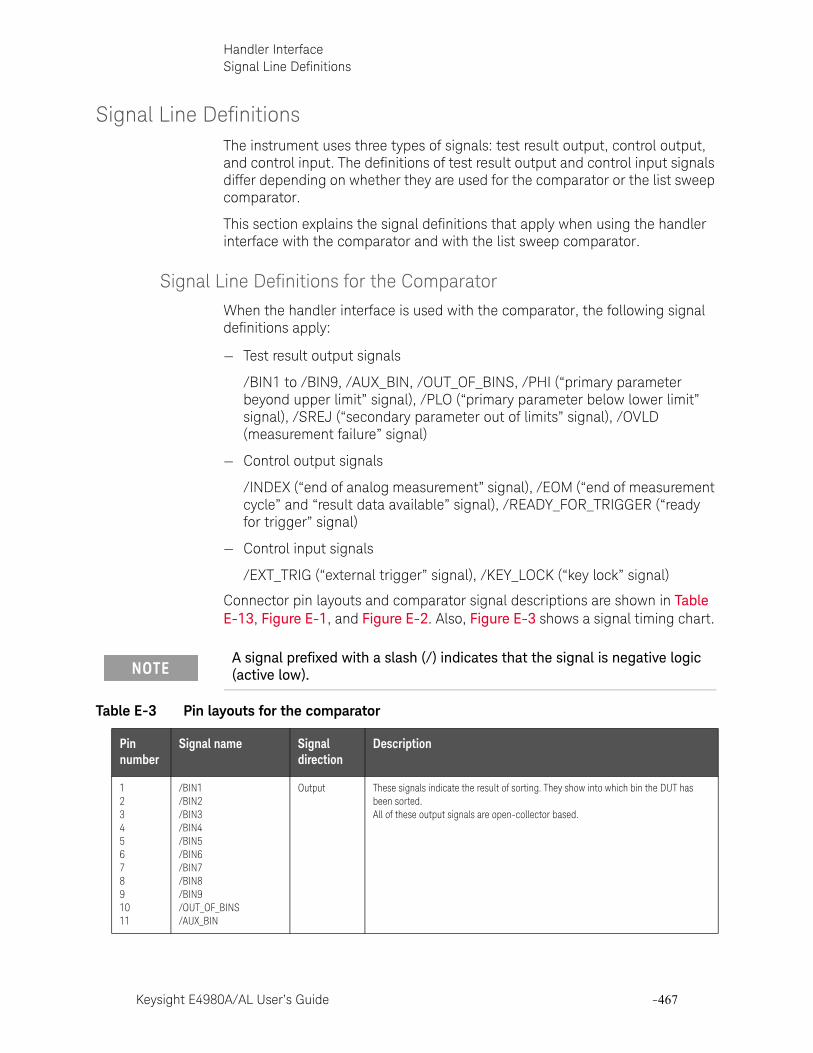
Keysight E4980A/AL User’s Guide -467
Handler InterfaceSignal Line Definitions
Signal Line DefinitionsThe instrument uses three types of signals: test result output, control output, and control input. The definitions of test result output and control input signals differ depending on whether they are used for the comparator or the list sweep comparator.
This section explains the signal definitions that apply when using the handler interface with the comparator and with the list sweep comparator.
Signal Line Definitions for the Comparator
When the handler interface is used with the comparator, the following signal definitions apply:
— Test result output signals
/BIN1 to /BIN9, /AUX_BIN, /OUT_OF_BINS, /PHI (“primary parameter beyond upper limit” signal), /PLO (“primary parameter below lower limit” signal), /SREJ (“secondary parameter out of limits” signal), /OVLD (measurement failure” signal)
— Control output signals
/INDEX (“end of analog measurement” signal), /EOM (“end of measurement cycle” and “result data available” signal), /READY_FOR_TRIGGER (“ready for trigger” signal)
— Control input signals
/EXT_TRIG (“external trigger” signal), /KEY_LOCK (“key lock” signal)
Connector pin layouts and comparator signal descriptions are shown in Table E-13, Figure E-1, and Figure E-2. Also, Figure E-3 shows a signal timing chart.
A signal prefixed with a slash (/) indicates that the signal is negative logic (active low).
Table E-3 Pin layouts for the comparator
Pin number
Signal name Signal direction
Description
1234567891011
/BIN1/BIN2/BIN3/BIN4/BIN5/BIN6/BIN7/BIN8/BIN9/OUT_OF_BINS/AUX_BIN
Output These signals indicate the result of sorting. They show into which bin the DUT has been sorted. All of these output signals are open-collector based.
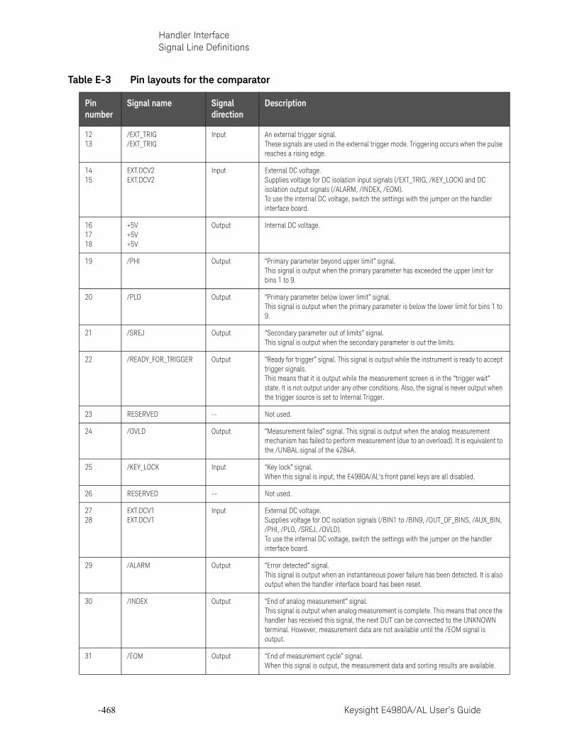
-468 Keysight E4980A/AL User’s Guide
Handler InterfaceSignal Line Definitions
-
1213
/EXT_TRIG/EXT_TRIG
Input An external trigger signal.These signals are used in the external trigger mode. Triggering occurs when the pulse reaches a rising edge.
1415
EXT.DCV2EXT.DCV2
Input External DC voltage.Supplies voltage for DC isolation input signals (/EXT_TRIG, /KEY_LOCK) and DC isolation output signals (/ALARM, /INDEX, /EOM). To use the internal DC voltage, switch the settings with the jumper on the handler interface board.
161718
+5V+5V+5V
Output Internal DC voltage.
19 /PHI Output “Primary parameter beyond upper limit” signal. This signal is output when the primary parameter has exceeded the upper limit for bins 1 to 9.
20 /PLO Output “Primary parameter below lower limit” signal. This signal is output when the primary parameter is below the lower limit for bins 1 to 9.
21 /SREJ Output “Secondary parameter out of limits” signal. This signal is output when the secondary parameter is out the limits.
22 /READY_FOR_TRIGGER Output “Ready for trigger” signal. This signal is output while the instrument is ready to accept trigger signals.This means that it is output while the measurement screen is in the “trigger wait” state. It is not output under any other conditions. Also, the signal is never output when the trigger source is set to Internal Trigger.
23 RESERVED -- Not used.
24 /OVLD Output “Measurement failed” signal. This signal is output when the analog measurement mechanism has failed to perform measurement (due to an overload). It is equivalent to the /UNBAL signal of the 4284A.
25 /KEY_LOCK Input “Key lock” signal.When this signal is input, the E4980A/AL's front panel keys are all disabled.
26 RESERVED -- Not used.
2728
EXT.DCV1EXT.DCV1
Input External DC voltage.Supplies voltage for DC isolation signals (/BIN1 to /BIN9, /OUT_OF_BINS, /AUX_BIN, /PHI, /PLO, /SREJ, /OVLD). To use the internal DC voltage, switch the settings with the jumper on the handler interface board.
29 /ALARM Output “Error detected” signal. This signal is output when an instantaneous power failure has been detected. It is also output when the handler interface board has been reset.
30 /INDEX Output “End of analog measurement” signal. This signal is output when analog measurement is complete. This means that once the handler has received this signal, the next DUT can be connected to the UNKNOWN terminal. However, measurement data are not available until the /EOM signal is output.
31 /EOM Output “End of measurement cycle” signal. When this signal is output, the measurement data and sorting results are available.
Table E-3 Pin layouts for the comparator
Pin number
Signal name Signal direction
Description

Keysight E4980A/AL User’s Guide -469
Handler InterfaceSignal Line Definitions
3233
COM2COM2
-- Common signals for external DC current EXT.DCV2.
343536
COM1COM1COM1
-- Common signals for external DC current EXT.DCV1.
Table E-3 Pin layouts for the comparator
Pin number
Signal name Signal direction
Description

-470 Keysight E4980A/AL User’s Guide
Handler InterfaceSignal Line Definitions
-
Figure E-1 Example of /PHI, /PLO, and /SREJ signal areas (for the comparator)
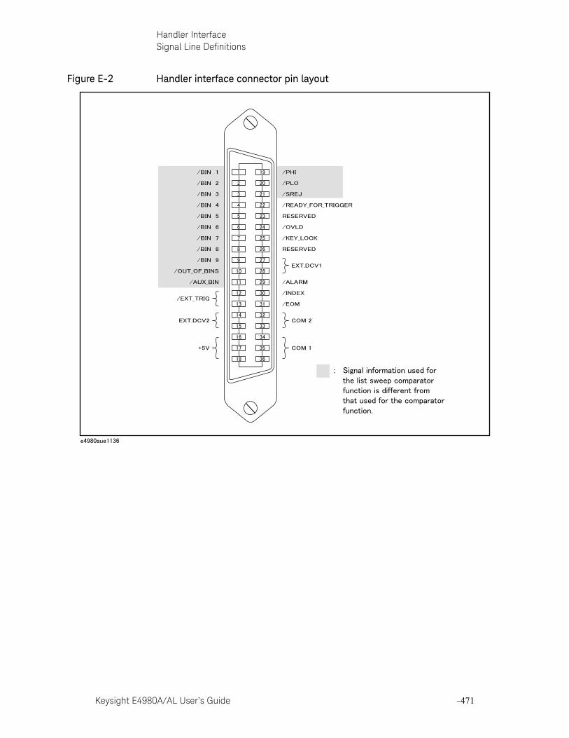
Keysight E4980A/AL User’s Guide -471
Handler InterfaceSignal Line Definitions
Figure E-2 Handler interface connector pin layout
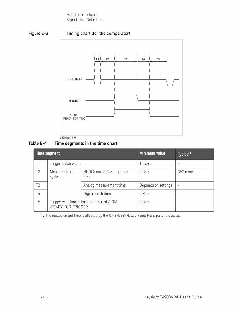
-472 Keysight E4980A/AL User’s Guide
Handler InterfaceSignal Line Definitions
-
Figure E-3 Timing chart (for the comparator)
Table E-4 Time segments in the time chart
Time segment Minimum value Typical1
1. The measurement time is affected by the GPIB/USB/Network and Front panel processes.
T1 Trigger pulse width 1 sec -
T2 Measurement cycle
/INDEX and /EOM response time
0 Sec 350 msec
T3 Analog measurement time Depends on settings -
T4 Digital math time 0 Sec
T5 Trigger wait time after the output of /EOM, /READY_FOR_TRIGGER
0 Sec -
/EXT_TRIG
/INDEX
/EOM,/READY_FOR_TRIG
T1 T2 T3 T4 T5

Keysight E4980A/AL User’s Guide -473
Handler InterfaceSignal Line Definitions
Signal Line Definitions for the List Sweep Comparator
The signal definitions for the list sweep comparator differ from those for the comparator.
When the handler interface is used with the list sweep comparator, the following signal definitions apply:
— Test result output signals
Signals /BIN1 to /BIN9 and /AUX_BIN represent the results of IN/OUT tests at sweep points 1 to 10, respectively. /OUT_OF_BINS indicates whether the DUT has passed or failed the test (a DUT fails the test if it generates an OUT result in any of steps 1 to 201 during one cycle of sweep measurement).
These signals are output at the end of the sweep cycle.
— Control output signals
The output timings of /INDEX (“end of analog measurement”) and /EOM (“end of measurement cycle”) signals differ depending on the sweep mode for list sweep (these signals behave differently than when used for the comparator).
1. SEQ sweep mode
/INDEX is output when the last analog measurement in the sweep cycle is complete. /EOM is output when all the comparator test results become available after the end of the sweep cycle.
2. STEP sweep mode
/INDEX is output when the analog measurement step in each step of the sweep cycle is complete. /EOM is output when the all the measurements in each step of the sweep cycle are complete (including the measurement time).
Connector pin layouts and comparator signal descriptions for the list sweep comparator are shown in Table E-13, Figure E-4, and Figure E-2. (the pin layouts for the list sweep comparator are the same as those for the comparator). Also, Figure E-5 shows a signal timing chart.
A signal prefixed with a slash (/) indicates that the signal is negative logic (active low).
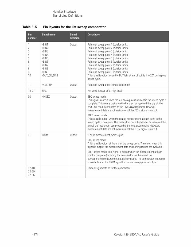
-474 Keysight E4980A/AL User’s Guide
Handler InterfaceSignal Line Definitions
-
Table E-5 Pin layouts for the list sweep comparator
Pin number
Signal name Signal direction
Description
12345678910
/BIN1/BIN2/BIN3/BIN4/BIN5/BIN6/BIN7/BIN8/BIN9/OUT_OF_BINS
Output Failure at sweep point 1 (outside limits)Failure at sweep point 2 (outside limits)Failure at sweep point 3 (outside limits)Failure at sweep point 4 (outside limits)Failure at sweep point 5 (outside limits)Failure at sweep point 6 (outside limits)Failure at sweep point 7 (outside limits)Failure at sweep point 8 (outside limits)Failure at sweep point 9 (outside limits)This signal is output when the DUT fails at any of points 1 to 201 during one sweep cycle.
11 /AUX_BIN Output Failure at sweep point 10 (outside limits)
19-21 N.U. -- Not used (always off at high level)
30 /INDEX Output SEQ sweep mode: This signal is output when the last analog measurement in the sweep cycle is complete. This means that once the handler has received this signal, the next DUT can be connected to the UNKNOWN terminal. However, measurement data are not available until the /EOM signal is output.
STEP sweep mode: This signal is output when the analog measurement at each point in the sweep cycle is complete. This means that once the handler has received this signal, the instrument can proceed to the next sweep point. However, measurement data are not available until the /EOM signal is output.
31 /EOM Output “End of measurement cycle” signal
SEQ sweep mode: This signal is output at the end of the sweep cycle. Therefore, when this signal is output, the measurement data and sorting results are available.
STEP sweep mode: This signal is output when the measurement at each point is complete (including the comparator test time) and the corresponding measurement data are available. The comparator test result is available after the /EOM signal for the last sweep point is output.
12-1822-2932-36
Same assignments as for the comparator.
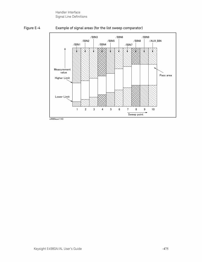
Keysight E4980A/AL User’s Guide -475
Handler InterfaceSignal Line Definitions
Figure E-4 Example of signal areas (for the list sweep comparator)

-476 Keysight E4980A/AL User’s Guide
Handler InterfaceSignal Line Definitions
-
Figure E-5 Timing chart (for the list sweep comparator)
Table E-6 Time segments in the time chart
Time segment Minimum value Typical1
T1 Trigger pulse width 1 sec -
T2 /INDEX and /EOM response time of measurement time 0 Sec 350 msec
T3
/EXT_TRIG
SEQ Sweep Mode:
/INDEX
/EOM
Data Previous Sweep's Data Valid Data Valid
MeasurementTiming
T1T2
a sweep
a measurement a measurement
SettlingTime
DelayTime
MeasurementTime
Comparison andDisplay Time
T3
/EXT_TRIG
STEP Sweep Mode:
/INDEX
/EOM
Data Previous Sweep's Data Valid Data Valid
MeasurementTiming
T1T2
a sweep
a measurement a measurement
SettlingTime
DelayTime
MeasurementTime
Comparison andDisplay Time
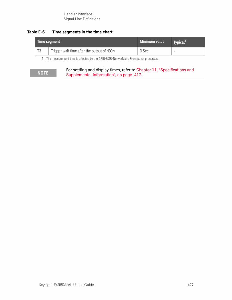
Keysight E4980A/AL User’s Guide -477
Handler InterfaceSignal Line Definitions
T3 Trigger wait time after the output of /EOM 0 Sec -
1. The measurement time is affected by the GPIB/USB/Network and Front panel processes.
For settling and display times, refer to Chapter 11, “Specifications and Supplemental Information”, on page 417.
Table E-6 Time segments in the time chart
Time segment Minimum value Typical1
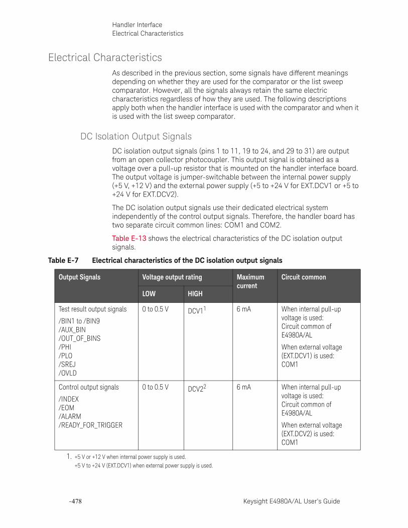
-478 Keysight E4980A/AL User’s Guide
Handler InterfaceElectrical Characteristics
-
Electrical CharacteristicsAs described in the previous section, some signals have different meanings depending on whether they are used for the comparator or the list sweep comparator. However, all the signals always retain the same electric characteristics regardless of how they are used. The following descriptions apply both when the handler interface is used with the comparator and when it is used with the list sweep comparator.
DC Isolation Output Signals
DC isolation output signals (pins 1 to 11, 19 to 24, and 29 to 31) are output from an open collector photocoupler. This output signal is obtained as a voltage over a pull-up resistor that is mounted on the handler interface board. The output voltage is jumper-switchable between the internal power supply (+5 V, +12 V) and the external power supply (+5 to +24 V for EXT.DCV1 or +5 to +24 V for EXT.DCV2).
The DC isolation output signals use their dedicated electrical system independently of the control output signals. Therefore, the handler board has two separate circuit common lines: COM1 and COM2.
Table E-13 shows the electrical characteristics of the DC isolation output signals.
Table E-7 Electrical characteristics of the DC isolation output signals
Output Signals Voltage output rating Maximum current
Circuit common
LOW HIGH
Test result output signals
/BIN1 to /BIN9/AUX_BIN/OUT_OF_BINS/PHI/PLO/SREJ/OVLD
0 to 0.5 V DCV11 6 mA When internal pull-up voltage is used: Circuit common of E4980A/AL
When external voltage (EXT.DCV1) is used: COM1
Control output signals
/INDEX/EOM/ALARM/READY_FOR_TRIGGER
0 to 0.5 V DCV22 6 mA When internal pull-up voltage is used: Circuit common of E4980A/AL
When external voltage (EXT.DCV2) is used: COM1
1. +5 V or +12 V when internal power supply is used. +5 V to +24 V (EXT.DCV1) when external power supply is used.

Keysight E4980A/AL User’s Guide -479
Handler InterfaceElectrical Characteristics
Figure E-6 shows the output circuit configuration for the test result output signals, and Figure E-7 shows that for the control output signals.
Figure E-6 Output circuit configuration for the test result output signals
2. +5 V or +12 V when internal power supply is used. +5 V to +24 V (EXT.DCV2) when external power supply is used.
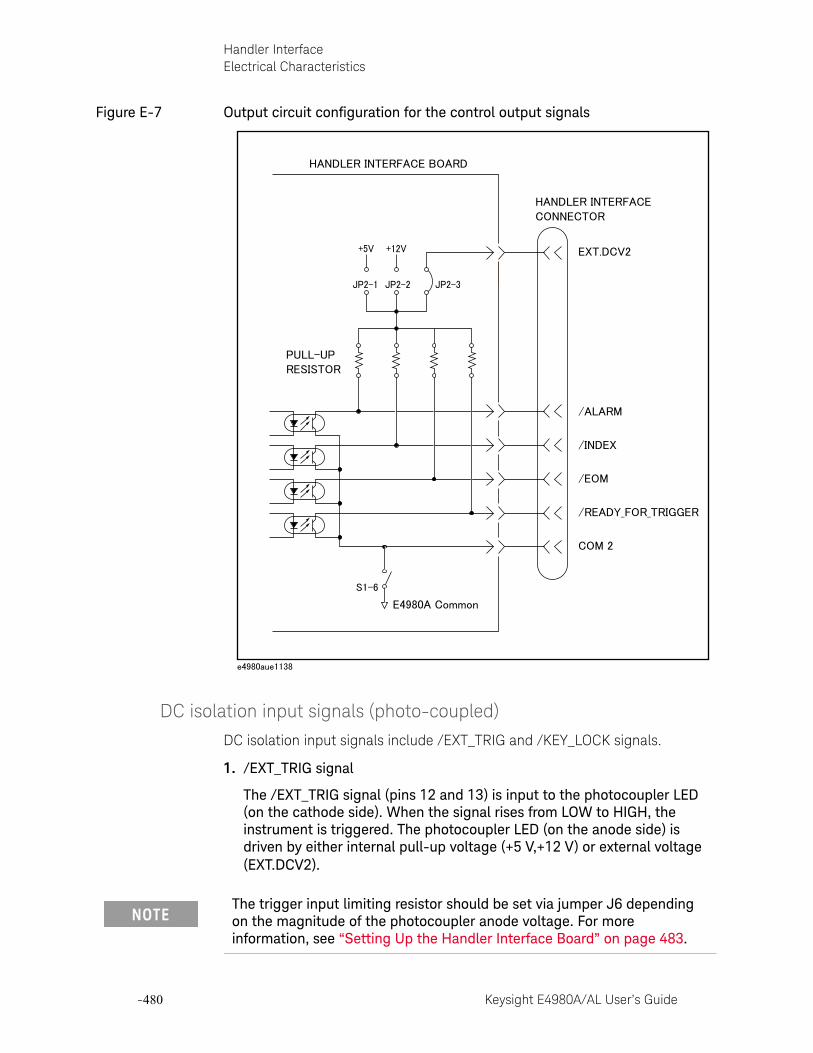
-480 Keysight E4980A/AL User’s Guide
Handler InterfaceElectrical Characteristics
-
Figure E-7 Output circuit configuration for the control output signals
DC isolation input signals (photo-coupled)
DC isolation input signals include /EXT_TRIG and /KEY_LOCK signals.
1. /EXT_TRIG signal
The /EXT_TRIG signal (pins 12 and 13) is input to the photocoupler LED (on the cathode side). When the signal rises from LOW to HIGH, the instrument is triggered. The photocoupler LED (on the anode side) is driven by either internal pull-up voltage (+5 V,+12 V) or external voltage (EXT.DCV2).
The trigger input limiting resistor should be set via jumper J6 depending on the magnitude of the photocoupler anode voltage. For more information, see “Setting Up the Handler Interface Board” on page 483.
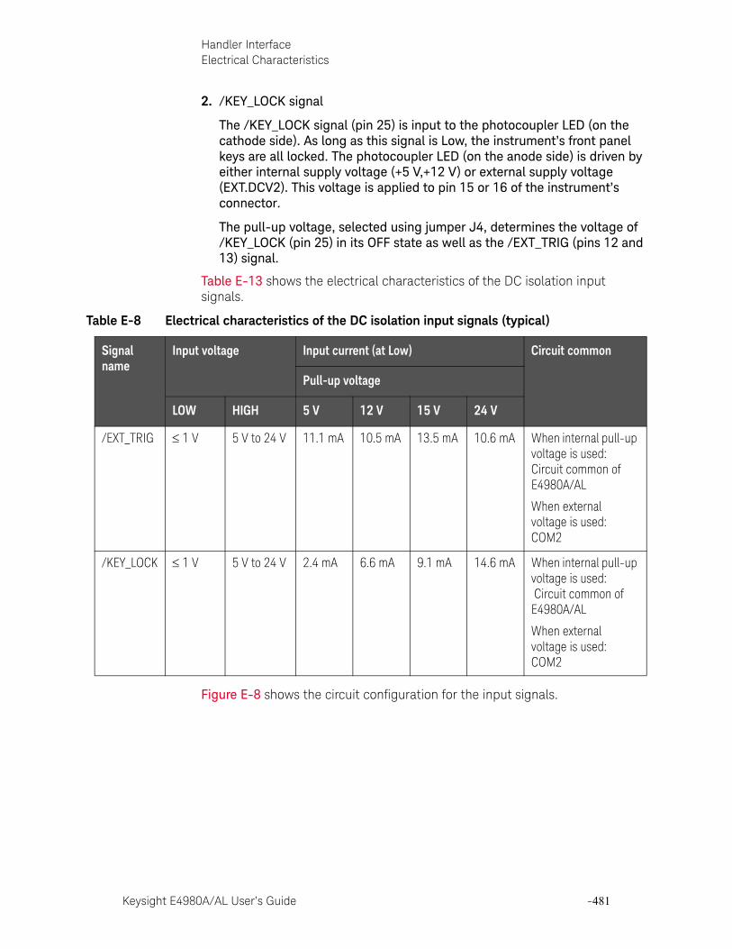
Keysight E4980A/AL User’s Guide -481
Handler InterfaceElectrical Characteristics
2. /KEY_LOCK signal
The /KEY_LOCK signal (pin 25) is input to the photocoupler LED (on the cathode side). As long as this signal is Low, the instrument’s front panel keys are all locked. The photocoupler LED (on the anode side) is driven by either internal supply voltage (+5 V,+12 V) or external supply voltage (EXT.DCV2). This voltage is applied to pin 15 or 16 of the instrument’s connector.
The pull-up voltage, selected using jumper J4, determines the voltage of /KEY_LOCK (pin 25) in its OFF state as well as the /EXT_TRIG (pins 12 and 13) signal.
Table E-13 shows the electrical characteristics of the DC isolation input signals.
Figure E-8 shows the circuit configuration for the input signals.
Table E-8 Electrical characteristics of the DC isolation input signals (typical)
Signal name
Input voltage Input current (at Low) Circuit common
Pull-up voltage
LOW HIGH 5 V 12 V 15 V 24 V
/EXT_TRIG 1 V 5 V to 24 V 11.1 mA 10.5 mA 13.5 mA 10.6 mA When internal pull-up voltage is used: Circuit common of E4980A/AL
When external voltage is used: COM2
/KEY_LOCK 1 V 5 V to 24 V 2.4 mA 6.6 mA 9.1 mA 14.6 mA When internal pull-up voltage is used: Circuit common of E4980A/AL
When external voltage is used: COM2
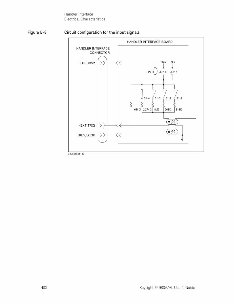
-482 Keysight E4980A/AL User’s Guide
Handler InterfaceElectrical Characteristics
-
Figure E-8 Circuit configuration for the input signals
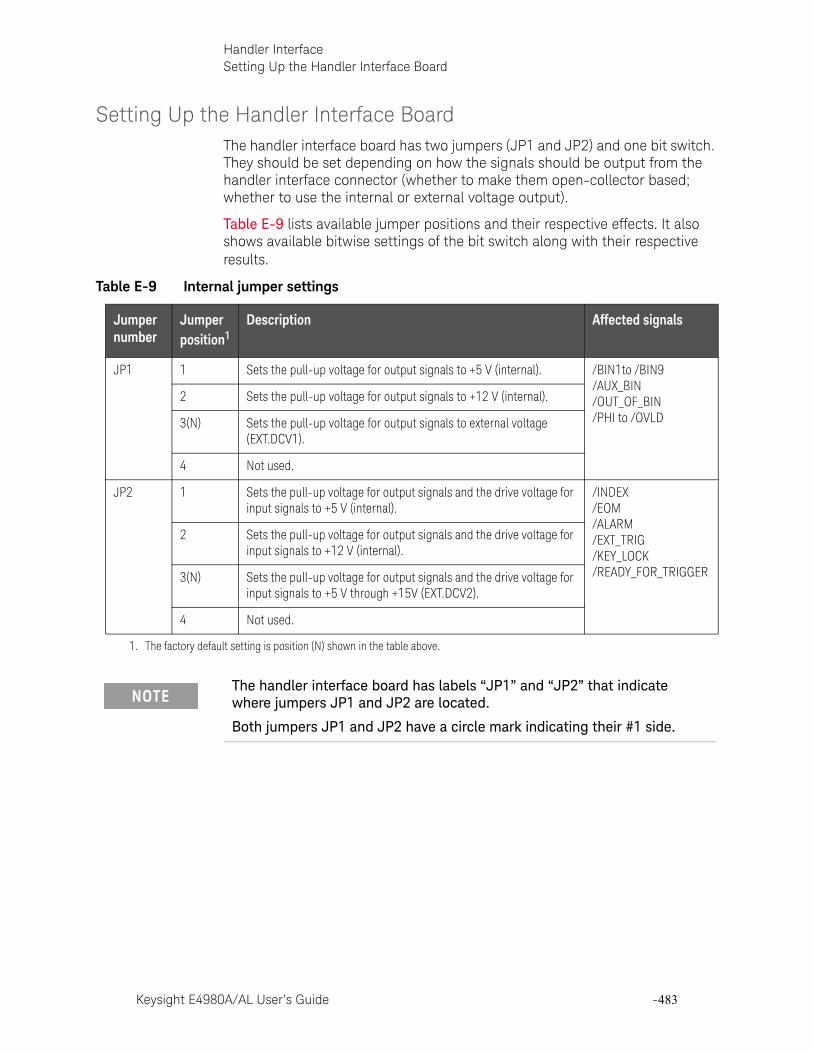
Keysight E4980A/AL User’s Guide -483
Handler InterfaceSetting Up the Handler Interface Board
Setting Up the Handler Interface BoardThe handler interface board has two jumpers (JP1 and JP2) and one bit switch. They should be set depending on how the signals should be output from the handler interface connector (whether to make them open-collector based; whether to use the internal or external voltage output).
Table E-9 lists available jumper positions and their respective effects. It also shows available bitwise settings of the bit switch along with their respective results.
Table E-9 Internal jumper settings
Jumper number
Jumper position1
Description Affected signals
JP1 1 Sets the pull-up voltage for output signals to +5 V (internal). /BIN1to /BIN9/AUX_BIN/OUT_OF_BIN/PHI to /OVLD
2 Sets the pull-up voltage for output signals to +12 V (internal).
3(N) Sets the pull-up voltage for output signals to external voltage (EXT.DCV1).
4 Not used.
JP2 1 Sets the pull-up voltage for output signals and the drive voltage for input signals to +5 V (internal).
/INDEX/EOM/ALARM/EXT_TRIG/KEY_LOCK/READY_FOR_TRIGGER
2 Sets the pull-up voltage for output signals and the drive voltage for input signals to +12 V (internal).
3(N) Sets the pull-up voltage for output signals and the drive voltage for input signals to +5 V through +15V (EXT.DCV2).
4 Not used.
1. The factory default setting is position (N) shown in the table above.
The handler interface board has labels “JP1” and “JP2” that indicate where jumpers JP1 and JP2 are located.
Both jumpers JP1 and JP2 have a circle mark indicating their #1 side.
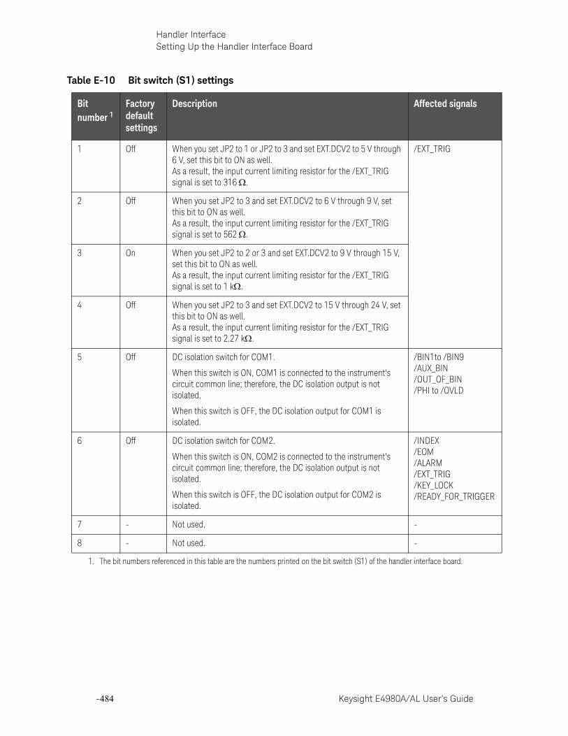
-484 Keysight E4980A/AL User’s Guide
Handler InterfaceSetting Up the Handler Interface Board
-
Table E-10 Bit switch (S1) settings
Bit number 1
Factory default settings
Description Affected signals
1 Off When you set JP2 to 1 or JP2 to 3 and set EXT.DCV2 to 5 V through 6 V, set this bit to ON as well. As a result, the input current limiting resistor for the /EXT_TRIG signal is set to 316 .
/EXT_TRIG
2 Off When you set JP2 to 3 and set EXT.DCV2 to 6 V through 9 V, set this bit to ON as well. As a result, the input current limiting resistor for the /EXT_TRIG signal is set to 562 .
3 On When you set JP2 to 2 or 3 and set EXT.DCV2 to 9 V through 15 V, set this bit to ON as well. As a result, the input current limiting resistor for the /EXT_TRIG signal is set to 1 k.
4 Off When you set JP2 to 3 and set EXT.DCV2 to 15 V through 24 V, set this bit to ON as well. As a result, the input current limiting resistor for the /EXT_TRIG signal is set to 2.27 k.
5 Off DC isolation switch for COM1.
When this switch is ON, COM1 is connected to the instrument's circuit common line; therefore, the DC isolation output is not isolated.
When this switch is OFF, the DC isolation output for COM1 is isolated.
/BIN1to /BIN9/AUX_BIN/OUT_OF_BIN/PHI to /OVLD
6 Off DC isolation switch for COM2.
When this switch is ON, COM2 is connected to the instrument's circuit common line; therefore, the DC isolation output is not isolated.
When this switch is OFF, the DC isolation output for COM2 is isolated.
/INDEX/EOM/ALARM/EXT_TRIG/KEY_LOCK/READY_FOR_TRIGGER
7 - Not used. -
8 - Not used. -
1. The bit numbers referenced in this table are the numbers printed on the bit switch (S1) of the handler interface board.
Keysight E4980A/AL User’s Guide -485
Handler InterfaceSetting Up the Handler Interface Board
Follow these steps to properly set up the jumpers and bit switch as well as the pull-up resistor.
Setting up the jumpers, bit switch, and pull-up resistor
Step 1. Turn off the power to the E4980A/AL, unplug the power cable, and wait for a few minutes until the internal capacitors are completely discharged.
Step 2. Remove the two screws that secure the handler interface board to the E4980A/AL’s rear panel.
Step 3. Draw out the handler interface board and unplug the flat cable that is connected to it.
Step 4. Remove the handler interface board.
Step 5. Go through the following flow chart to determine the jumper and bit switch settings for the test result output signals:
The handler interface board has a label “S1” that indicates where bit switch S1 is located.
Only one of bits 1 through 4 can be ON at a time. You cannot turn ON any more than one bit at a time.
When you use the +5-V output of the handler interface connector (pins 16 to 18), set up the circuit common line by turning ON bit 5 or 6 of bit switch S1 and use COM1 or COM 2 connected with the instrument's circuit common line as a +5-V common line.
Do not disconnect the handler interface board from the instrument immediately after turning on or off the power to the E4980A/AL. Doing so could damage the handler interface board and the E4980A/AL itself.
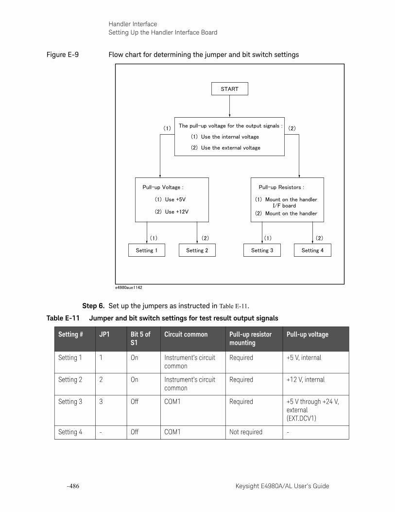
-486 Keysight E4980A/AL User’s Guide
Handler InterfaceSetting Up the Handler Interface Board
-
Figure E-9 Flow chart for determining the jumper and bit switch settings
Step 6. Set up the jumpers as instructed in Table E-11.
Table E-11 Jumper and bit switch settings for test result output signals
Setting # JP1 Bit 5 of S1
Circuit common Pull-up resistor mounting
Pull-up voltage
Setting 1 1 On Instrument’s circuit common
Required +5 V, internal
Setting 2 2 On Instrument’s circuit common
Required +12 V, internal
Setting 3 3 Off COM1 Required +5 V through +24 V, external(EXT.DCV1)
Setting 4 - Off COM1 Not required -
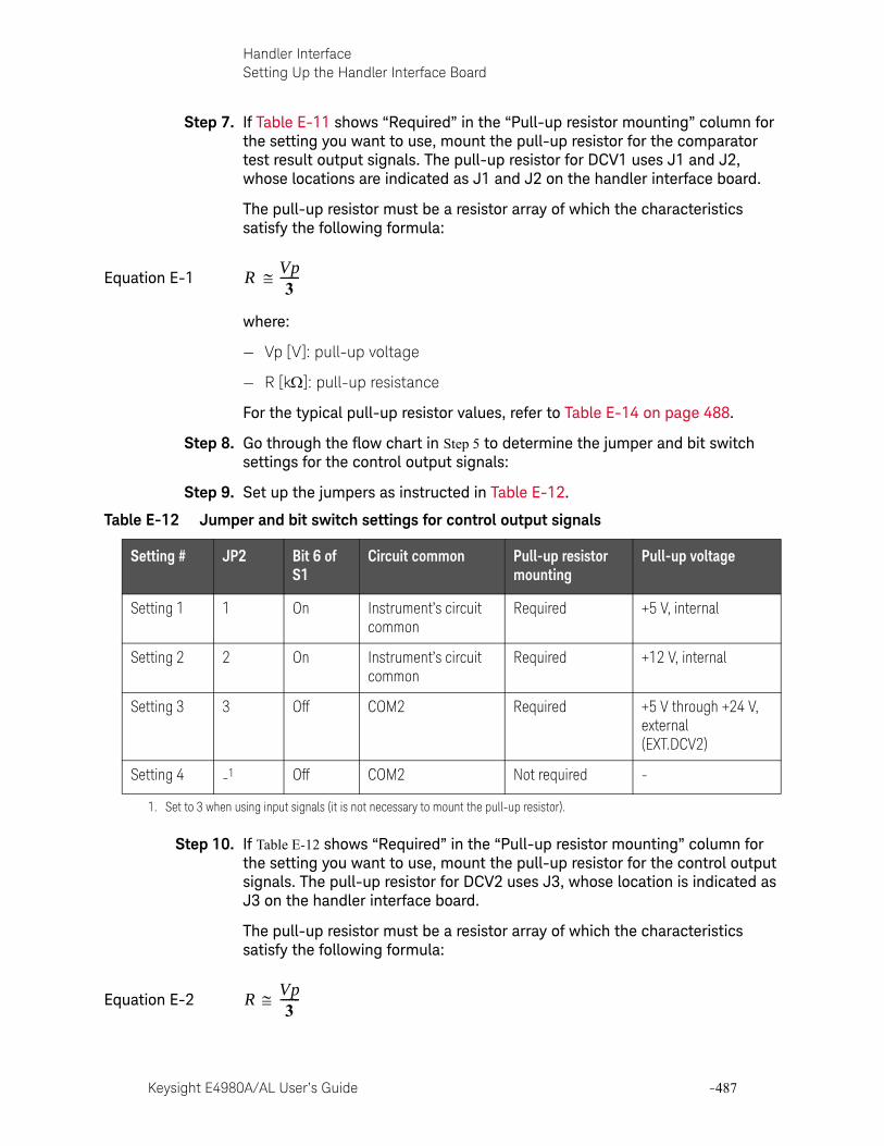
Keysight E4980A/AL User’s Guide -487
Handler InterfaceSetting Up the Handler Interface Board
Step 7. If Table E-11 shows “Required” in the “Pull-up resistor mounting” column for the setting you want to use, mount the pull-up resistor for the comparator test result output signals. The pull-up resistor for DCV1 uses J1 and J2, whose locations are indicated as J1 and J2 on the handler interface board.
The pull-up resistor must be a resistor array of which the characteristics satisfy the following formula:
Equation E-1
where:
— Vp [V]: pull-up voltage
— R [k]: pull-up resistance
For the typical pull-up resistor values, refer to Table E-14 on page 488.
Step 8. Go through the flow chart in Step 5 to determine the jumper and bit switch settings for the control output signals:
Step 9. Set up the jumpers as instructed in Table E-12.
Step 10. If Table E-12 shows “Required” in the “Pull-up resistor mounting” column for the setting you want to use, mount the pull-up resistor for the control output signals. The pull-up resistor for DCV2 uses J3, whose location is indicated as J3 on the handler interface board.
The pull-up resistor must be a resistor array of which the characteristics satisfy the following formula:
Equation E-2
RVp3
-------
Table E-12 Jumper and bit switch settings for control output signals
Setting # JP2 Bit 6 of S1
Circuit common Pull-up resistor mounting
Pull-up voltage
Setting 1 1 On Instrument’s circuit common
Required +5 V, internal
Setting 2 2 On Instrument’s circuit common
Required +12 V, internal
Setting 3 3 Off COM2 Required +5 V through +24 V, external(EXT.DCV2)
Setting 4 -1
1. Set to 3 when using input signals (it is not necessary to mount the pull-up resistor).
Off COM2 Not required -
RVp3
-------
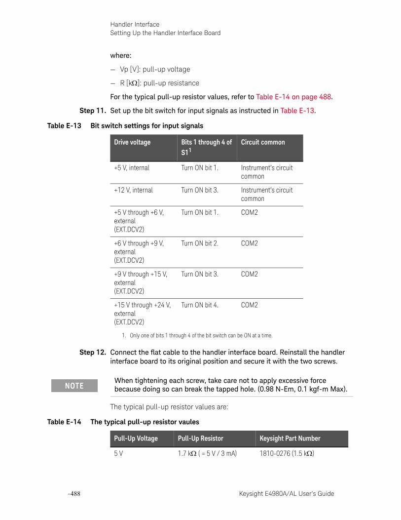
-488 Keysight E4980A/AL User’s Guide
Handler InterfaceSetting Up the Handler Interface Board
-
where:
— Vp [V]: pull-up voltage
— R [k]: pull-up resistance
For the typical pull-up resistor values, refer to Table E-14 on page 488.
Step 11. Set up the bit switch for input signals as instructed in Table E-13.
Step 12. Connect the flat cable to the handler interface board. Reinstall the handler interface board to its original position and secure it with the two screws.
The typical pull-up resistor values are:
Table E-13 Bit switch settings for input signals
Drive voltage Bits 1 through 4 of S11
1. Only one of bits 1 through 4 of the bit switch can be ON at a time.
Circuit common
+5 V, internal Turn ON bit 1. Instrument’s circuit common
+12 V, internal Turn ON bit 3. Instrument’s circuit common
+5 V through +6 V, external(EXT.DCV2)
Turn ON bit 1. COM2
+6 V through +9 V, external(EXT.DCV2)
Turn ON bit 2. COM2
+9 V through +15 V, external(EXT.DCV2)
Turn ON bit 3. COM2
+15 V through +24 V, external(EXT.DCV2)
Turn ON bit 4. COM2
When tightening each screw, take care not to apply excessive force because doing so can break the tapped hole. (0.98 N-Em, 0.1 kgf-m Max).
Table E-14 The typical pull-up resistor vaules
Pull-Up Voltage Pull-Up Resistor Keysight Part Number
5 V 1.7 k ( = 5 V / 3 mA) 1810-0276 (1.5 k)
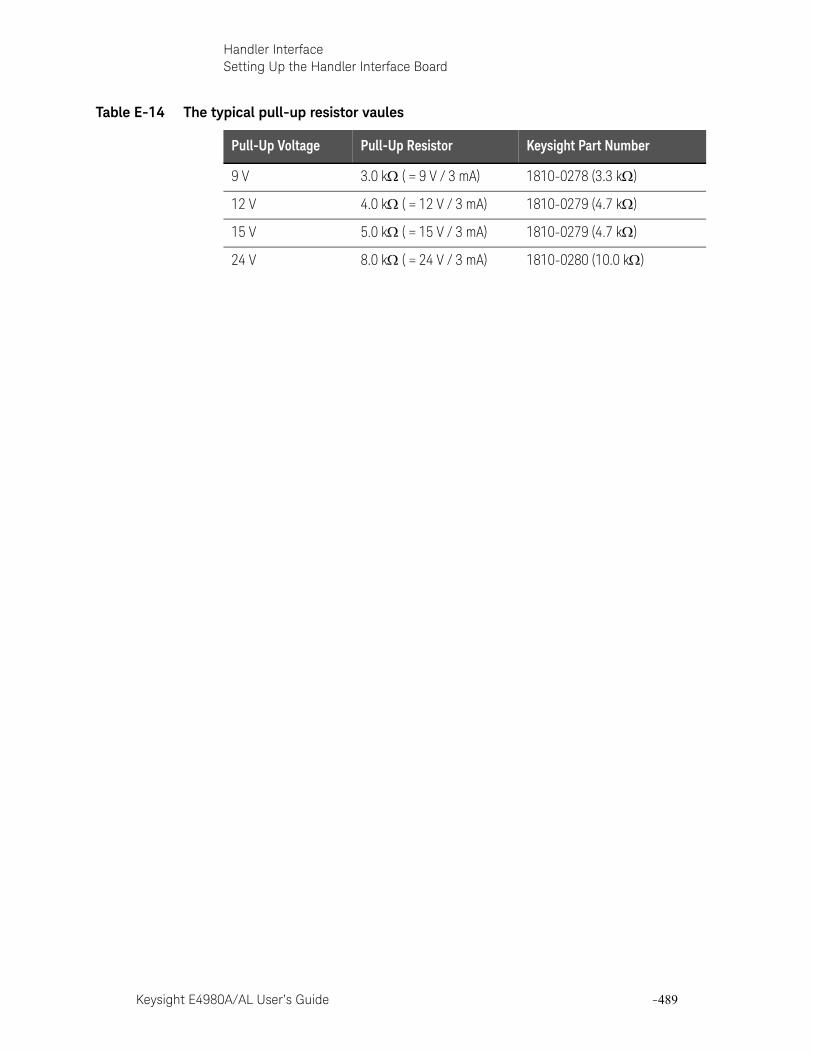
Keysight E4980A/AL User’s Guide -489
Handler InterfaceSetting Up the Handler Interface Board
9 V 3.0 k ( = 9 V / 3 mA) 1810-0278 (3.3 k)
12 V 4.0 k ( = 12 V / 3 mA) 1810-0279 (4.7 k)
15 V 5.0 k ( = 15 V / 3 mA) 1810-0279 (4.7 k)
24 V 8.0 k ( = 24 V / 3 mA) 1810-0280 (10.0 k)
Table E-14 The typical pull-up resistor vaules
Pull-Up Voltage Pull-Up Resistor Keysight Part Number
-490 Keysight E4980A/AL User’s Guide
Handler InterfaceUsing the Handler Interface
-
Using the Handler InterfaceBefore you can use the handler interface, you need to set up the handler interface board. Then, set up the limit table for the comparator or the list sweep table for the list sweep comparator. Finally, enable the handler interface for signal input/output.
This section provides the handler interface setup procedures for the comparator and the list sweep comparator.
Setting Up the Handler Interface for Use with the Comparator
To set up the handler interface for the comparator, follow these steps:
Step 1. Press [Meas Setup] - LIMIT TABLE to open the LIMIT TABLE SETUP page.
Step 2. Set up the limit table for bin sorting. For more information, see the chapter on “Configuring Measurement Conditions.”
Step 3. Using the cursor movement keys on the front panel, move the cursor to the COMP field. The following softkeys appear on the softkey label area.
— ON
— OFF
Step 4. Press the ON softkey. The comparator is enabled.
Step 5. Press the [System] key to open the SYSTEM INFO page.
Step 6. Using the cursor movement keys on the front panel, move the cursor to the HANDLER I/F field. The following softkeys appear on the softkey label area.
— ON
— OFF
Step 7. Press the ON softkey. The handler interface is enabled for signal input/output.
Step 8. Press the [Display Format] key to open the MEAS DISPLAY page. Prepare for measurement by pressing one of the following softkeys: MEAS DISPLAY, BIN No., and BIN COUNT.
You can also use the BIN No. DISPLAY page to enable or disable the comparator.

Keysight E4980A/AL User’s Guide -491
Handler InterfaceUsing the Handler Interface
Setting Up the Handler Interface Board for Use with the List Sweep Comparator
Follow these steps to set up the handler interface for the list sweep comparator:
Step 1. [Meas Setup] - LIST SETUP to open the LIST SWEEP SETUP page.
Step 2. Set up the list table (by defining the sweep points and upper/lower limits) so that you can conduct list sweep measurement. For more information, see the chapter on “Configuring Measurement Conditions.”
Step 3. Press the [System] key to open the SYSTEM INFO page.
Step 4. Using the cursor movement keys on the front panel, move the cursor to the HANDLER I/F field. The following softkeys appear on the softkey label area.
— ON
— OFF
Step 5. Press the ON softkey. The handler interface is enabled for signal input/output.
Step 6. Press the [Display Format] key to open the MEAS DISPLAY page. Press the LIST SWEEP softkey so that you can begin list sweep measurement.
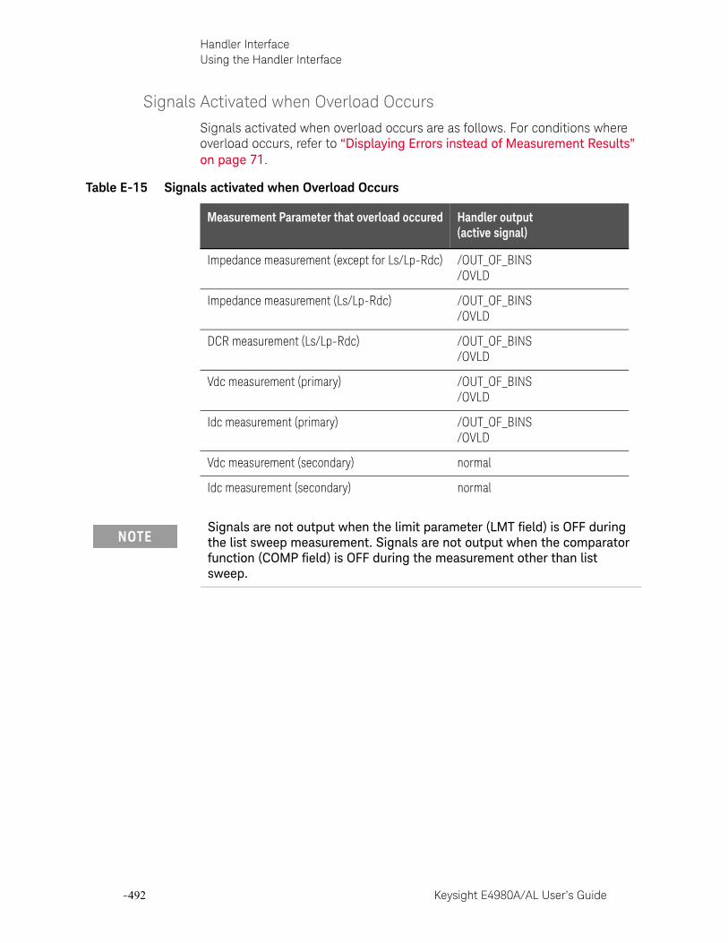
-492 Keysight E4980A/AL User’s Guide
Handler InterfaceUsing the Handler Interface
-
Signals Activated when Overload Occurs
Signals activated when overload occurs are as follows. For conditions where overload occurs, refer to “Displaying Errors instead of Measurement Results” on page 71.
Table E-15 Signals activated when Overload Occurs
Measurement Parameter that overload occured Handler output(active signal)
Impedance measurement (except for Ls/Lp-Rdc) /OUT_OF_BINS/OVLD
Impedance measurement (Ls/Lp-Rdc) /OUT_OF_BINS/OVLD
DCR measurement (Ls/Lp-Rdc) /OUT_OF_BINS/OVLD
Vdc measurement (primary) /OUT_OF_BINS/OVLD
Idc measurement (primary) /OUT_OF_BINS/OVLD
Vdc measurement (secondary) normal
Idc measurement (secondary) normal
Signals are not output when the limit parameter (LMT field) is OFF during the list sweep measurement. Signals are not output when the comparator function (COMP field) is OFF during the measurement other than list sweep.

Keysight E4980A/AL User’s Guide -493
Keysight E4980A/ALPrecision LCR Meter
User’s Guide
F Scanner Interface
This chapter provides electrical characteristics of the interface signal line necessary to use the Keysight E4980A/AL Precision LCR meter option 301.
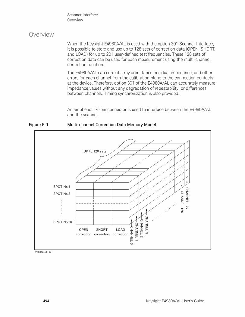
-494 Keysight E4980A/AL User’s Guide
Scanner InterfaceOverview
-
OverviewWhen the Keysight E4980A/AL is used with the option 301 Scanner Interface, it is possible to store and use up to 128 sets of correction data (OPEN, SHORT, and LOAD) for up to 201 user-defined test frequencies. These 128 sets of correction data can be used for each measurement using the multi-channel correction function.
The E4980A/AL can correct stray admittance, residual impedance, and other errors for each channel from the calibration plane to the connection contacts at the device. Therefore, option 301 of the E4980A/AL can accurately measure impedance values without any degradation of repeatability, or differences between channels. Timing synchronization is also provided.
An amphenol 14-pin connector is used to interface between the E4980A/AL and the scanner.
Figure F-1 Multi-channel Correction Data Memory Model
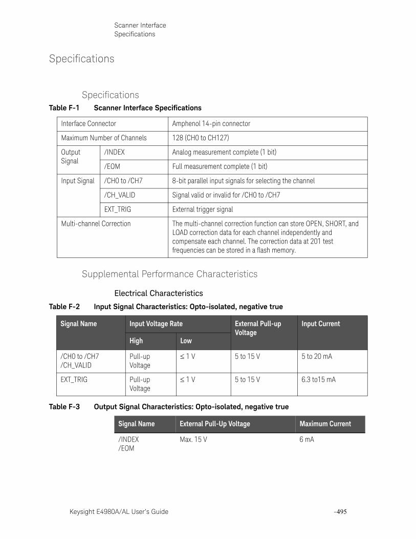
Keysight E4980A/AL User’s Guide -495
Scanner InterfaceSpecifications
Specifications
Specifications
Supplemental Performance Characteristics
Electrical Characteristics
Table F-1 Scanner Interface Specifications
Interface Connector Amphenol 14-pin connector
Maximum Number of Channels 128 (CH0 to CH127)
Output Signal
/INDEX Analog measurement complete (1 bit)
/EOM Full measurement complete (1 bit)
Input Signal /CH0 to /CH7 8-bit parallel input signals for selecting the channel
/CH_VALID Signal valid or invalid for /CH0 to /CH7
EXT_TRIG External trigger signal
Multi-channel Correction The multi-channel correction function can store OPEN, SHORT, and LOAD correction data for each channel independently and compensate each channel. The correction data at 201 test frequencies can be stored in a flash memory.
Table F-2 Input Signal Characteristics: Opto-isolated, negative true
Signal Name Input Voltage Rate External Pull-up Voltage
Input Current
High Low
/CH0 to /CH7/CH_VALID
Pull-up Voltage
1 V 5 to 15 V 5 to 20 mA
EXT_TRIG Pull-up Voltage
1 V 5 to 15 V 6.3 to15 mA
Table F-3 Output Signal Characteristics: Opto-isolated, negative true
Signal Name External Pull-Up Voltage Maximum Current
/INDEX/EOM
Max. 15 V 6 mA
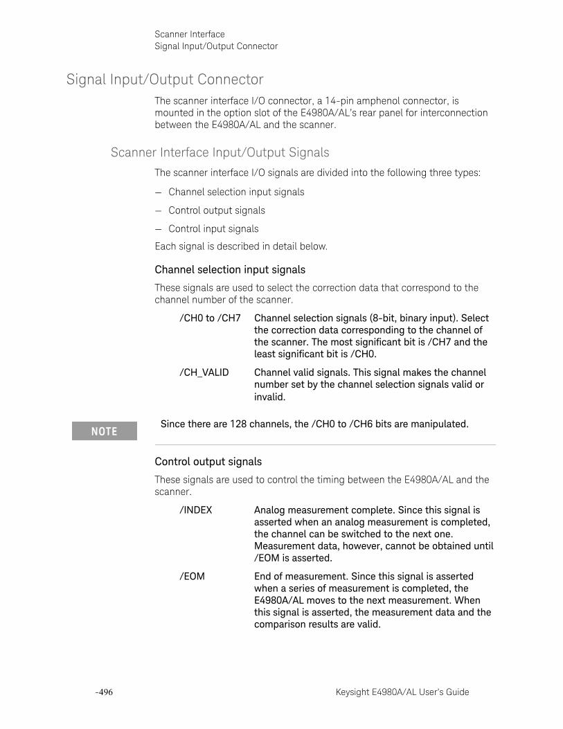
-496 Keysight E4980A/AL User’s Guide
Scanner InterfaceSignal Input/Output Connector
-
Signal Input/Output ConnectorThe scanner interface I/O connector, a 14-pin amphenol connector, is mounted in the option slot of the E4980A/AL’s rear panel for interconnection between the E4980A/AL and the scanner.
Scanner Interface Input/Output Signals
The scanner interface I/O signals are divided into the following three types:
— Channel selection input signals
— Control output signals
— Control input signals
Each signal is described in detail below.
Channel selection input signals
These signals are used to select the correction data that correspond to the channel number of the scanner.
/CH0 to /CH7 Channel selection signals (8-bit, binary input). Select the correction data corresponding to the channel of the scanner. The most significant bit is /CH7 and the least significant bit is /CH0.
/CH_VALID Channel valid signals. This signal makes the channel number set by the channel selection signals valid or invalid.
Control output signals
These signals are used to control the timing between the E4980A/AL and the scanner.
/INDEX Analog measurement complete. Since this signal is asserted when an analog measurement is completed, the channel can be switched to the next one. Measurement data, however, cannot be obtained until /EOM is asserted.
/EOM End of measurement. Since this signal is asserted when a series of measurement is completed, the E4980A/AL moves to the next measurement. When this signal is asserted, the measurement data and the comparison results are valid.
Since there are 128 channels, the /CH0 to /CH6 bits are manipulated.
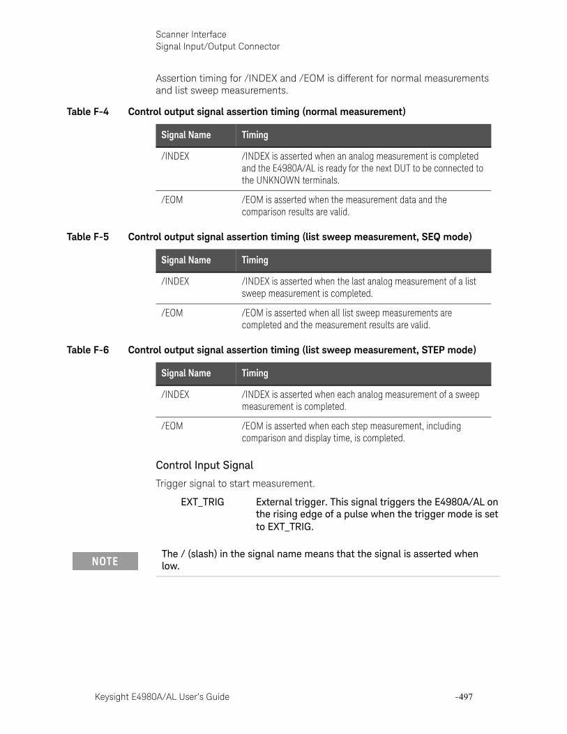
Keysight E4980A/AL User’s Guide -497
Scanner InterfaceSignal Input/Output Connector
Assertion timing for /INDEX and /EOM is different for normal measurements and list sweep measurements.
Control Input Signal
Trigger signal to start measurement.
EXT_TRIG External trigger. This signal triggers the E4980A/AL on the rising edge of a pulse when the trigger mode is set to EXT_TRIG.
Table F-4 Control output signal assertion timing (normal measurement)
Signal Name Timing
/INDEX /INDEX is asserted when an analog measurement is completed and the E4980A/AL is ready for the next DUT to be connected to the UNKNOWN terminals.
/EOM /EOM is asserted when the measurement data and the comparison results are valid.
Table F-5 Control output signal assertion timing (list sweep measurement, SEQ mode)
Signal Name Timing
/INDEX /INDEX is asserted when the last analog measurement of a list sweep measurement is completed.
/EOM /EOM is asserted when all list sweep measurements are completed and the measurement results are valid.
Table F-6 Control output signal assertion timing (list sweep measurement, STEP mode)
Signal Name Timing
/INDEX /INDEX is asserted when each analog measurement of a sweep measurement is completed.
/EOM /EOM is asserted when each step measurement, including comparison and display time, is completed.
The / (slash) in the signal name means that the signal is asserted when low.
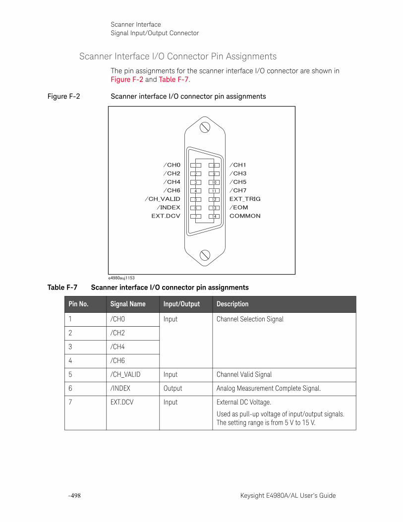
-498 Keysight E4980A/AL User’s Guide
Scanner InterfaceSignal Input/Output Connector
-
Scanner Interface I/O Connector Pin Assignments
The pin assignments for the scanner interface I/O connector are shown in Figure F-2 and Table F-7.
Figure F-2 Scanner interface I/O connector pin assignments
Table F-7 Scanner interface I/O connector pin assignments
Pin No. Signal Name Input/Output Description
1 /CH0 Input Channel Selection Signal
2 /CH2
3 /CH4
4 /CH6
5 /CH_VALID Input Channel Valid Signal
6 /INDEX Output Analog Measurement Complete Signal.
7 EXT.DCV Input External DC Voltage.
Used as pull-up voltage of input/output signals. The setting range is from 5 V to 15 V.
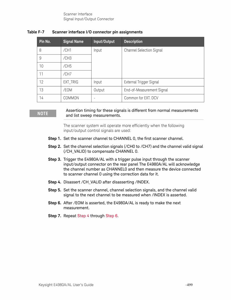
Keysight E4980A/AL User’s Guide -499
Scanner InterfaceSignal Input/Output Connector
The scanner system will operate more efficiently when the following input/output control signals are used:
Step 1. Set the scanner channel to CHANNEL 0, the first scanner channel.
Step 2. Set the channel selection signals (/CH0 to /CH7) and the channel valid signal (/CH_VALID) to compensate CHANNEL 0.
Step 3. Trigger the E4980A/AL with a trigger pulse input through the scanner input/output connector on the rear panel The E4980A/AL will acknowledge the channel number as CHANNEL0 and then measure the device connected to scanner channel 0 using the correction data for it.
Step 4. Disassert /CH_VALID after disasserting /INDEX.
Step 5. Set the scanner channel, channel selection signals, and the channel valid signal to the next channel to be measured when /INDEX is asserted.
Step 6. After /EOM is asserted, the E4980A/AL is ready to make the next measurement.
Step 7. Repeat Step 4 through Step 6.
8 /CH1 Input Channel Selection Signal
9 /CH3
10 /CH5
11 /CH7
12 EXT_TRIG Input External Trigger Signal
13 /EOM Output End-of-Measurement Signal
14 COMMON - Common for EXT. DCV
Assertion timing for these signals is different from normal measurements and list sweep measurements.
Table F-7 Scanner interface I/O connector pin assignments
Pin No. Signal Name Input/Output Description
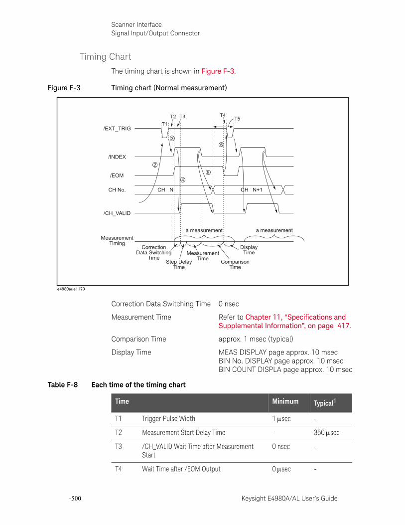
-500 Keysight E4980A/AL User’s Guide
Scanner InterfaceSignal Input/Output Connector
-
Timing Chart
The timing chart is shown in Figure F-3.
Figure F-3 Timing chart (Normal measurement)
Correction Data Switching Time 0 nsec
Measurement Time Refer to Chapter 11, “Specifications and Supplemental Information”, on page 417.
Comparison Time approx. 1 msec (typical)
Display Time MEAS DISPLAY page approx. 10 msecBIN No. DISPLAY page approx. 10 msecBIN COUNT DISPLA page approx. 10 msec
T4
/EXT_TRIG
/INDEX
/EOM
CH No.
/CH_VALID
CH N CH N+1
MeasurementTiming
T1T2 T3
a measurement a measurement
CorrectionData Switching
TimeStep Delay
Time
MeasurementTime Comparison
Time
T5
DisplayTime
3
2
45
6
Table F-8 Each time of the timing chart
Time Minimum Typical1
T1 Trigger Pulse Width 1 sec -
T2 Measurement Start Delay Time - 350 sec
T3 /CH_VALID Wait Time after Measurement Start
0 nsec -
T4 Wait Time after /EOM Output 0 sec -

Keysight E4980A/AL User’s Guide -501
Scanner InterfaceSignal Input/Output Connector
T5 /CH_VALID Setup Time 0 sec -
1. The measurement time is affected by the GPIB/USB/Network and Front panel processes.
Table F-8 Each time of the timing chart
Time Minimum Typical1
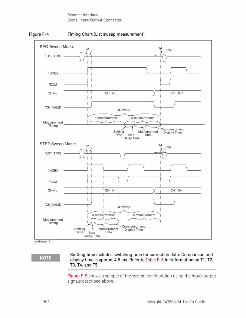
-502 Keysight E4980A/AL User’s Guide
Scanner InterfaceSignal Input/Output Connector
-
Figure F-4 Timing Chart (List sweep measurement)
Figure F-5 shows a sample of the system configuration using the input/output signals described above.
Settling time includes switching time for correction data. Comparison and display time is approx. 4.5 ms. Refer to Table F-8 for information on T1, T2, T3, T4, and T5.
T4
/EXT_TRIG
SEQ Sweep Mode:
/INDEX
/EOM
CH No.
/CH_VALID
CH N CH N+1
MeasurementTiming
T1T2 T3
a sweep
a measurement a measurement
SettlingTime Step
Delay Time
MeasurementTime
Comparison andDisplay Time
STEP Sweep Mode:
T5
T4
/EXT_TRIG
/INDEX
/EOM
CH No.
/CH_VALID
CH N CH N+1
MeasurementTiming
T1T2 T3
a sweep
a measurement a measurement
SettlingTime Step
Delay Time
MeasurementTime
Comparison andDisplay Time
T5
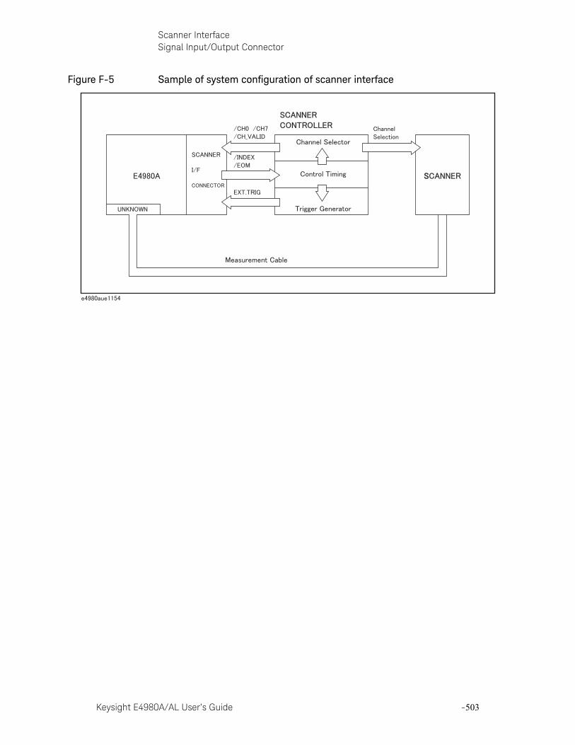
Keysight E4980A/AL User’s Guide -503
Scanner InterfaceSignal Input/Output Connector
Figure F-5 Sample of system configuration of scanner interface
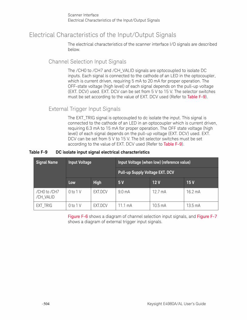
-504 Keysight E4980A/AL User’s Guide
Scanner InterfaceElectrical Characteristics of the Input/Output Signals
-
Electrical Characteristics of the Input/Output SignalsThe electrical characteristics of the scanner interface I/O signals are described below.
Channel Selection Input Signals
The /CH0 to /CH7 and /CH_VALID signals are optocoupled to isolate DC inputs. Each signal is connected to the cathode of an LED in the optocoupler, which is current driven, requiring 5 mA to 20 mA for proper operation. The OFF-state voltage (high level) of each signal depends on the pull-up voltage (EXT. DCV) used. EXT. DCV can be set from 5 V to 15 V. The selector switches must be set according to the value of EXT. DCV used (Refer to Table F-9).
External Trigger Input Signals
The EXT_TRIG signal is optocoupled to dc isolate the input. This signal is connected to the cathode of an LED in an optocoupler which is current driven, requiring 6.3 mA to 15 mA for proper operation. The OFF state voltage (high level) of each signal depends on the pull-up voltage (EXT. DCV) used. EXT. DCV can be set from 5 V to 15 V. The bit selector switches must be set according to the value of EXT. DCV used (Refer to Table F-9).
Figure F-6 shows a diagram of channel selection input signals, and Figure F-7 shows a diagram of external trigger input signals.
Table F-9 DC isolate input signal electrical characteristics
Signal Name Input Voltage Input Voltage (when low) (reference value)
Pull-up Supply Voltage EXT. DCV
Low High 5 V 12 V 15 V
/CH0 to /CH7/CH_VALID
0 to 1 V EXT.DCV 9.0 mA 12.7 mA 16.2 mA
EXT_TRIG 0 to 1 V EXT.DCV 11.1 mA 10.5 mA 13.5 mA
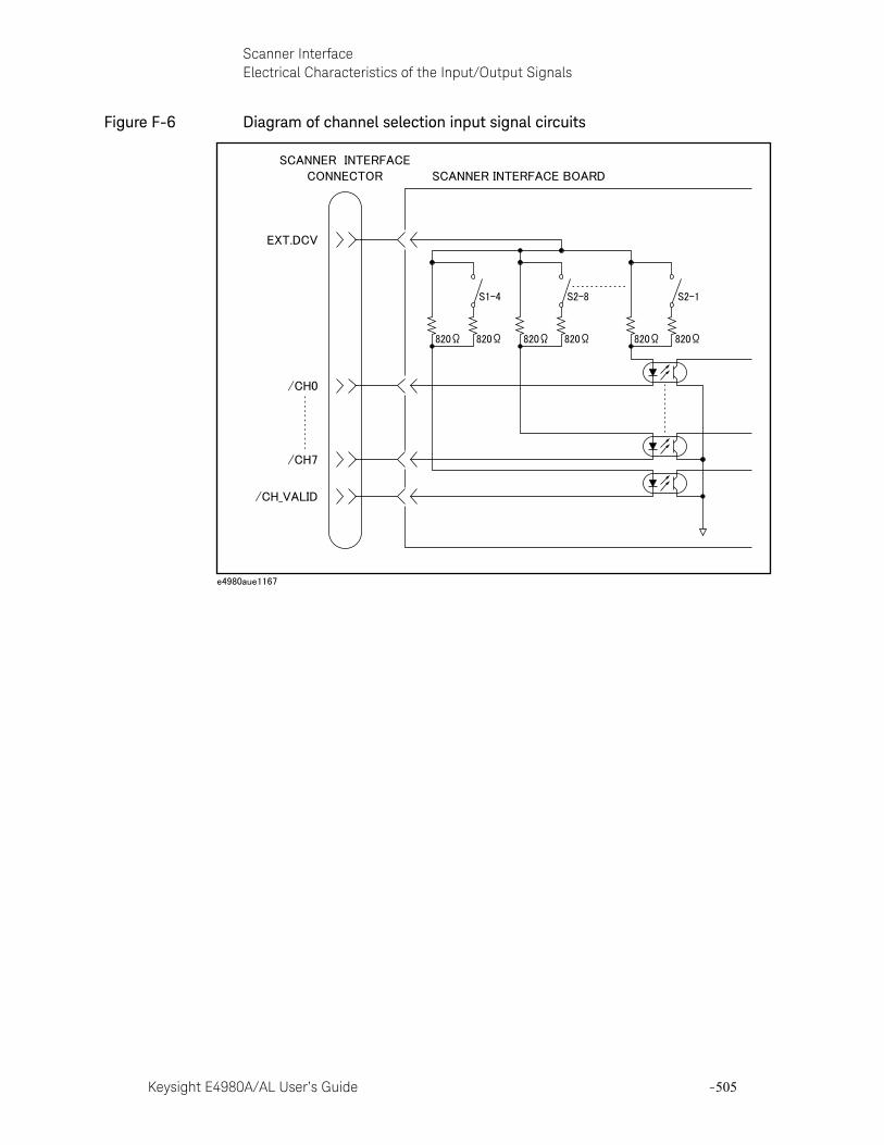
Keysight E4980A/AL User’s Guide -505
Scanner InterfaceElectrical Characteristics of the Input/Output Signals
Figure F-6 Diagram of channel selection input signal circuits
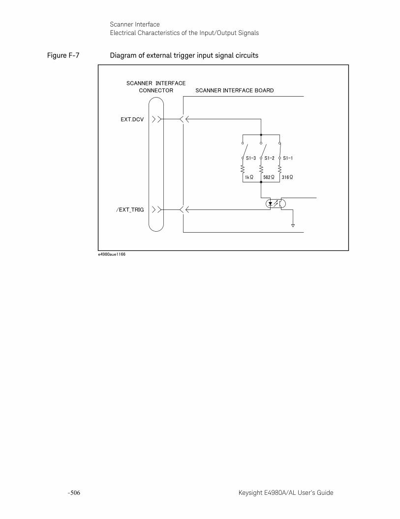
-506 Keysight E4980A/AL User’s Guide
Scanner InterfaceElectrical Characteristics of the Input/Output Signals
-
Figure F-7 Diagram of external trigger input signal circuits
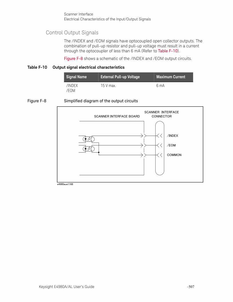
Keysight E4980A/AL User’s Guide -507
Scanner InterfaceElectrical Characteristics of the Input/Output Signals
Control Output Signals
The /INDEX and /EOM signals have optocoupled open collector outputs. The combination of pull-up resistor and pull-up voltage must result in a current through the optocoupler of less than 6 mA (Refer to Table F-10).
Figure F-8 shows a schematic of the /INDEX and /EOM output circuits.
Figure F-8 Simplified diagram of the output circuits
Table F-10 Output signal electrical characteristics
Signal Name External Pull-up Voltage Maximum Current
/INDEX/EOM
15 V max. 6 mA
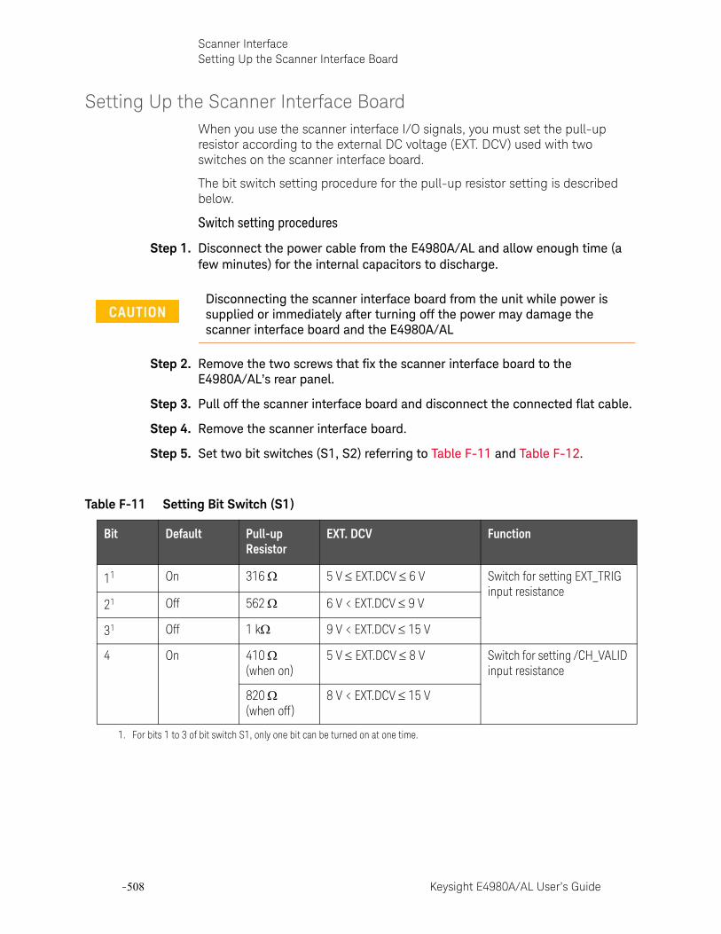
-508 Keysight E4980A/AL User’s Guide
Scanner InterfaceSetting Up the Scanner Interface Board
-
Setting Up the Scanner Interface BoardWhen you use the scanner interface I/O signals, you must set the pull-up resistor according to the external DC voltage (EXT. DCV) used with two switches on the scanner interface board.
The bit switch setting procedure for the pull-up resistor setting is described below.
Switch setting procedures
Step 1. Disconnect the power cable from the E4980A/AL and allow enough time (a few minutes) for the internal capacitors to discharge.
Step 2. Remove the two screws that fix the scanner interface board to the E4980A/AL’s rear panel.
Step 3. Pull off the scanner interface board and disconnect the connected flat cable.
Step 4. Remove the scanner interface board.
Step 5. Set two bit switches (S1, S2) referring to Table F-11 and Table F-12.
Disconnecting the scanner interface board from the unit while power is supplied or immediately after turning off the power may damage the scanner interface board and the E4980A/AL
Table F-11 Setting Bit Switch (S1)
Bit Default Pull-up Resistor
EXT. DCV Function
11 On 316 5 V EXT.DCV 6 V Switch for setting EXT_TRIG input resistance
21 Off 562 6 V < EXT.DCV 9 V
31 Off 1 k 9 V < EXT.DCV 15 V
4 On 410 (when on)
5 V EXT.DCV 8 V Switch for setting /CH_VALID input resistance
820 (when off )
8 V < EXT.DCV 15 V
1. For bits 1 to 3 of bit switch S1, only one bit can be turned on at one time.

Keysight E4980A/AL User’s Guide -509
Scanner InterfaceSetting Up the Scanner Interface Board
Step 6. Connect the flat cable to the scanner interface board, replace the scanner interface board, and fix it onto place with the two screws.
Table F-12 Setting Bit Switch (S2)
Bit Default Pull-up Resistor
EXT. DCV Function
1-8 On 410 (When on)
5 V EXT.DCV 8 V /CH0 to /CH7SW for input resistance
820 (When off )
8 V < EXT.DCV 15 V
Bit switches S1 and S2 can be identified by the labels “S1” and “S2” on the scanner interface board.
Applying excessive force to the screws may break the tapped hole (less than 0.98 N-m, 0.1 kgf-m).
-510 Keysight E4980A/AL User’s Guide
Scanner InterfaceHow to Use the Scanner Interface Board
-
How to Use the Scanner Interface BoardThis section provides information necessary for the E4980A/AL to operate using the scanner interface.
Basic Procedure
Figure F-9 shows a sample procedure for using the scanner interface. Follow this flow chart while referring to the following detailed descriptions.
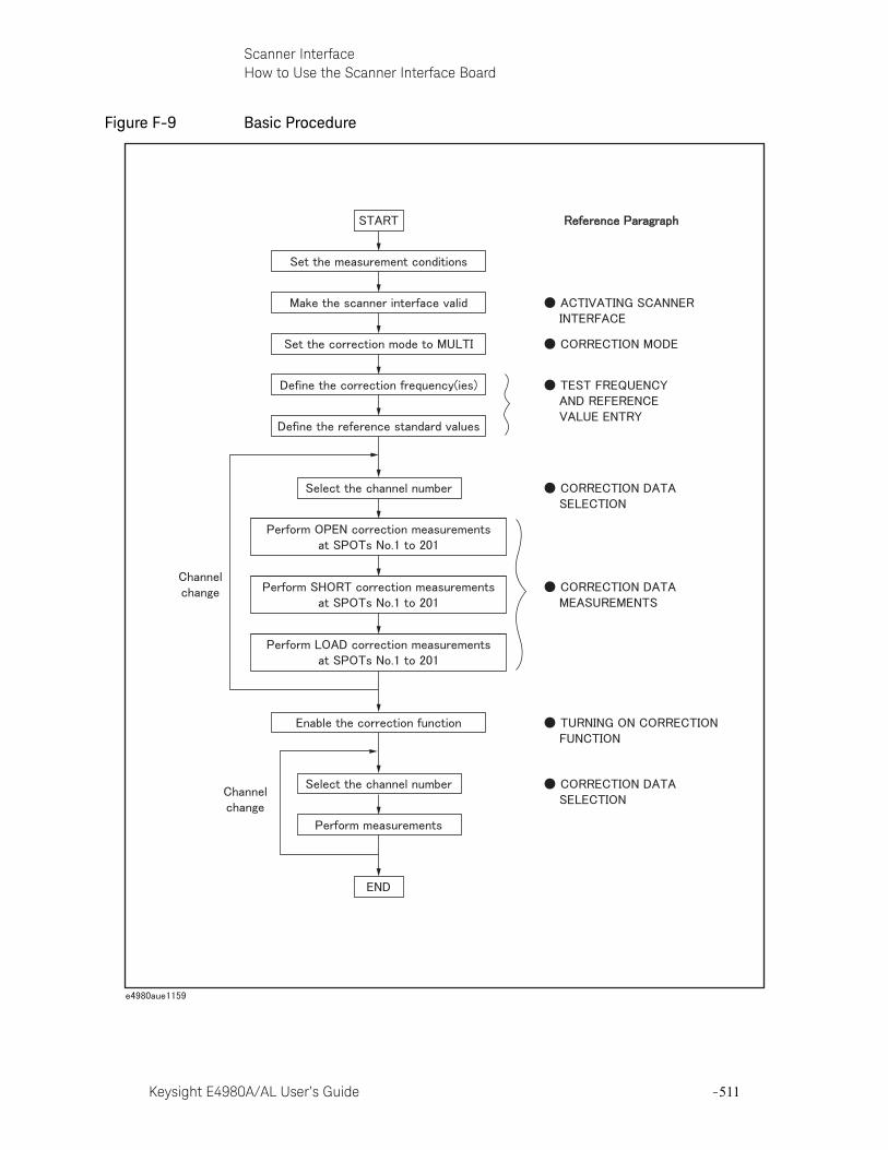
Keysight E4980A/AL User’s Guide -511
Scanner InterfaceHow to Use the Scanner Interface Board
Figure F-9 Basic Procedure
-512 Keysight E4980A/AL User’s Guide
Scanner InterfaceHow to Use the Scanner Interface Board
-
Activating Scanner Interface
Make the scanner interface valid to perform multi-channel correction and to input/output signals through the interface connector on the E4980A/AL’s rear panel.
Step 1. Press the [System] key to display the SYSTEM INFO page.
Step 2. Use the cursor arrow keys to move the cursor to the SCANNER I/F field. The following softkeys are displayed in the softkey label area.
— ON
— OFF
Step 3. Press the ON softkey. The scanner interface is now valid for output/input signals.
Correction Mode
Set the correction mode to MULTI to use the multi-channel correction function.
Step 1. Press the [Meas Setup] - CORRECTION to display the CORRECTION page.
Step 2. Use the cursor arrow keys on the front panel to move the cursor to the MODE field. The following softkeys are displayed in the softkey label area.
— SINGLE
— MULTI
Step 3. Press the MULTI softkey to use the multi-channel correction function.
Test Frequency and Reference Value Entry
It is possible to store the correction data for 201 test frequencies. These test frequencies are defined and monitored on the CORRECTION page.
On this page, the reference values (REF A and REF B) of the standards used for LOAD correction are defined at 201 test frequencies. The reference values can be stored with an appropriate function (FUNC). For example, to use the
Even when multi-channel correction is used without the interface connector (for example, controlling a scanner and the E4980A/AL via GPIB), the following procedure must be performed.
Before setting the correction mode to MULTI, you need to set the scanner interface to ON.
Keysight E4980A/AL User’s Guide -513
Scanner InterfaceHow to Use the Scanner Interface Board
standard capacitor that has reference parallel capacitance and D values, the reference values should be stored with the Cp-D function. The reference values are also stored on the CORRECTION page.
The setting procedure is given below.
Step 1. Press the [Meas Setup] - CORRECTION to display the CORRECTION page.
Step 2. Use the cursor arrow keys on the front panel to move the cursor to the FUNC field.
Step 3. Use the softkeys to select the function to be used for entering the reference values.
Step 4. Use the cursor arrow keys on the front panel to move the cursor to the SPOT No. field.
Step 5. Use the numeric entry keys or softkeys on the front panel to enter a measurement point number for entering the reference value.
Step 6. Use the cursor arrow keys on the front panel to move the cursor to the FREQ field.
Step 7. When the FREQ field is OFF, press the ON softkey to use the correction data of the measurement point number.
Step 8. Use the numeric entry keys and softkeys on the front panel to enter a test frequency at a specific measurement point.
Step 9. Use the cursor arrow keys on the front panel to move the cursor to the REF A field.
Step 10. Use the numeric entry keys and softkeys on the front panel to enter the reference value of the primary parameter at the specified measurement point.
Step 11. Use the cursor arrow keys on the front panel to move the cursor to the REF B field.
Step 12. Use the numeric entry keys and softkeys on the front panel to enter the reference value of the secondary parameter at the specified measurement point.
The function of the standard on the CORRECTION page can be defined independently of the measurement function set on the MEAS SETUP page. For example, if the reference values are defined as the Cp-D function (entered with capacitance value and D value), the Z- parameter can be measured while performing the correction.

-514 Keysight E4980A/AL User’s Guide
Scanner InterfaceHow to Use the Scanner Interface Board
-
Step 13. If necessary, move the cursor to the SPOT No. field and repeat steps 4 to 12 for other measurement points (frequency points).
Correction Data Selection
Up to 128 sets of correction data for each scanner channel can be stored in the flash memory. Each set of correction data can be arbitrarily assigned a channel number for selection of correction data. You can set the channel number using the /CHO to /CH7 signals, and the /CH_VALID signals, or the :CORR:USE command via GPIB.
Channel Selection using Front Panel
Enter the channel number in the CH field on the CORRECTION page to set the channel number. Steps are shown below.
Step 1. Press the [Meas Setup] - CORRECTION to display the CORRECTION page.
Step 2. Use the cursor arrow keys to move the cursor to the CH field.
Step 3. Use the numeric entry keys or softkeys on the front panel to enter the channel number.
Channel Selection using Interface Connector
You can set the channel number with the channel selection signals (/CH0 to /CH7) and the channel valid signal (/CH_VALID). The /CH0 to /CH7 signals are 8-bit binary signals. /CH0 is the LSB (least significant bit) and /CH7 is the MSB (most significant bit). An example is given below in Table F-13
If a test frequency is not equal to any of the correction frequencies, correction (including OPEN, SHORT and LOAD) is not performed. In this case, the E4980A/AL displays the raw measurement value including additional error due to the test fixture’s residuals.
Table F-13 Example of Channel Selection
/CH0 /CH1 /CH2 /CH3 /CH4 /CH5 /CH6 /CH7 Channel Number
1 0 0 0 0 0 0 0 1
0 1 0 0 0 0 0 0 2
0 0 1 0 0 0 0 0 4
0 0 0 1 0 0 0 0 8
0 0 0 0 1 0 0 0 16
0 0 0 0 0 1 0 0 32
0 0 0 0 0 0 1 0 64
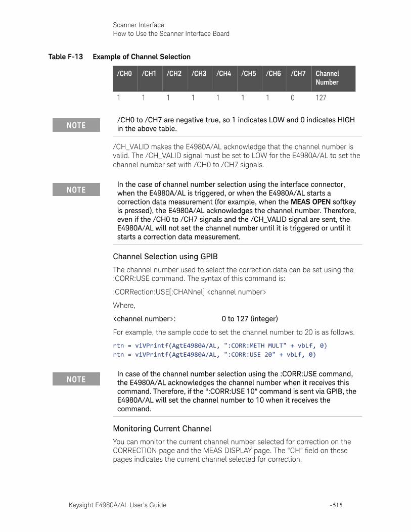
Keysight E4980A/AL User’s Guide -515
Scanner InterfaceHow to Use the Scanner Interface Board
/CH_VALID makes the E4980A/AL acknowledge that the channel number is valid. The /CH_VALID signal must be set to LOW for the E4980A/AL to set the channel number set with /CH0 to /CH7 signals.
Channel Selection using GPIB
The channel number used to select the correction data can be set using the :CORR:USE command. The syntax of this command is:
:CORRection:USE[:CHANnel] <channel number>
Where,
<channel number>: 0 to 127 (integer)
For example, the sample code to set the channel number to 20 is as follows.
rtn = viVPrintf(AgtE4980A/AL, ":CORR:METH MULT" + vbLf, 0)rtn = viVPrintf(AgtE4980A/AL, ":CORR:USE 20" + vbLf, 0)
Monitoring Current Channel
You can monitor the current channel number selected for correction on the CORRECTION page and the MEAS DISPLAY page. The “CH” field on these pages indicates the current channel selected for correction.
1 1 1 1 1 1 1 0 127
/CH0 to /CH7 are negative true, so 1 indicates LOW and 0 indicates HIGH in the above table.
Table F-13 Example of Channel Selection
/CH0 /CH1 /CH2 /CH3 /CH4 /CH5 /CH6 /CH7 Channel Number
In the case of channel number selection using the interface connector, when the E4980A/AL is triggered, or when the E4980A/AL starts a correction data measurement (for example, when the MEAS OPEN softkey is pressed), the E4980A/AL acknowledges the channel number. Therefore, even if the /CH0 to /CH7 signals and the /CH_VALID signal are sent, the E4980A/AL will not set the channel number until it is triggered or until it starts a correction data measurement.
In case of the channel number selection using the :CORR:USE command, the E4980A/AL acknowledges the channel number when it receives this command. Therefore, if the “:CORR:USE 10” command is sent via GPIB, the E4980A/AL will set the channel number to 10 when it receives the command.
-516 Keysight E4980A/AL User’s Guide
Scanner InterfaceHow to Use the Scanner Interface Board
-
Correction Data Measurements
For correction data measurements, it is necessary to perform OPEN, SHORT, and LOAD data measurements at 201 test frequencies for each channel.
The following is a sample procedure for performing correction data measurements for a channel. Repeat the following procedure for each scanner channel to be used.
Step 1. Select the scanner channel.
Step 2. Press the [Meas Setup] - CORRECTION key to display the CORRECTION page.
Step 3. Set the E4980A/AL’s channel number equal to that selected in Step 1.
Step 4. [OPEN correction]
Open the measurement contacts of the selected scanner channel.
Step 5. Use the cursor arrow keys on the front panel to move the cursor to the SPOT No. field.
Step 6. Use the numeric entry keys or softkeys on the front panel to enter the measurement point number to perform an OPEN measurement.
Step 7. Use the cursor arrow keys on the front panel to move the cursor to the FREQ field.
Step 8. Press the MEAS OPEN softkey to measure OPEN condition at a specified test frequency.
Step 9. If necessary, repeat steps 5 to 8 for other measurement points (other frequencies).
Step 10. [SHORT correction]
Short the measurement contacts of the selected scanner channel.
Step 11. Use the cursor arrow keys on the front panel to move the cursor to the SPOT No. field.
Step 12. Use the numeric entry keys or softkeys to enter the measurement point number to perform a SHORT measurement.
Step 13. Use the cursor arrow keys on the front panel to move the cursor to the FREQ field.
Step 14. Press the MEAS SHORT softkey to measure SHORT condition at a specified test frequency.
Step 15. If necessary, repeat steps 11 to 14 for other measurement points (other frequencies).
Step 16. [LOAD correction]
Use the cursor arrow keys on the front panel to move the cursor to the SPOT No. field.
Keysight E4980A/AL User’s Guide -517
Scanner InterfaceHow to Use the Scanner Interface Board
Step 17. Use the numeric entry keys or softkeys on the front panel to enter the measurement point number to perform a LOAD measurement.
Step 18. Connect the standard for test frequency correction of a specified measurement point number to the measurement contacts of the selected scanner channel.
Step 19. Use the cursor arrow keys on the front panel to move the cursor to the FREQ field.
Step 20. Press the MEAS LOAD softkey to measure the standard at a specified frequency.
Step 21. If necessary, repeat steps 16 to 20 for other measurement points (other frequencies).
Step 22. Change the scanner’s and the E4980A/AL’s channel number and repeat steps 4 to 21 until this procedure has been performed for all scanner channels.
Activating the Correction Function
Set the correction function to ON in the following procedure in order to perform the correction using the correction data.
Step 1. Press the [Meas Setup] - CORRECTION to display the CORRECTION page.
Step 2. Use the cursor arrow keys on the front panel to move the cursor to the SPOT No. field.
Step 3. Use the numeric entry keys or the softkeys on the front panel to enter the measurement point number, and confirm that the correction frequencies to be used (test frequencies of the measurement point number entered) are set to ON (test frequency and reference values are displayed and OFF is not displayed).
Step 4. Use the cursor arrow keys on the front panel to move the cursor to the OPEN field.
Step 5. Press the “ON” softkey to set the OPEN correction function to ON.
Step 6. Use the cursor arrow keys on the front panel to move the cursor to the SHORT field.
Step 7. Press the “ON” softkey to set the SHORT correction function to ON.
Step 8. Use the cursor arrow keys on the front panel to move the cursor to the LOAD field.
Step 9. Press the “ON” softkey to set the LOAD correction function to ON.
Correction Data Confirmation
There are two ways to confirm the measurement data for each channel correction: Use the front panel, and read the data using a query via GPIB.
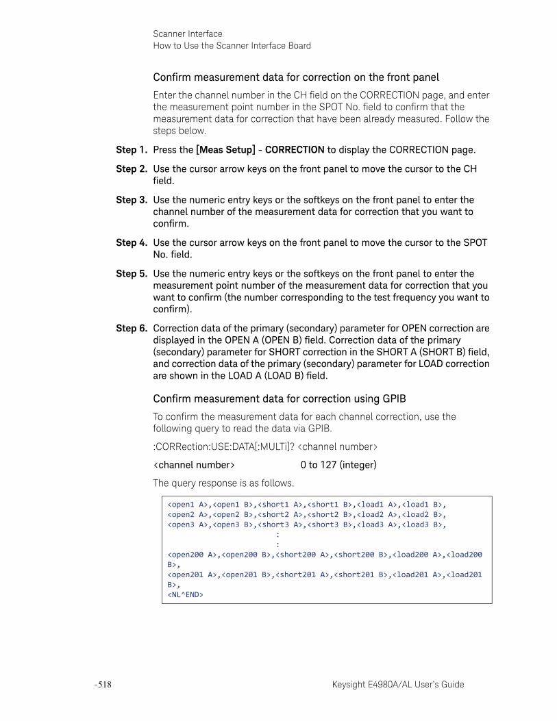
-518 Keysight E4980A/AL User’s Guide
Scanner InterfaceHow to Use the Scanner Interface Board
-
Confirm measurement data for correction on the front panel
Enter the channel number in the CH field on the CORRECTION page, and enter the measurement point number in the SPOT No. field to confirm that the measurement data for correction that have been already measured. Follow the steps below.
Step 1. Press the [Meas Setup] - CORRECTION to display the CORRECTION page.
Step 2. Use the cursor arrow keys on the front panel to move the cursor to the CH field.
Step 3. Use the numeric entry keys or the softkeys on the front panel to enter the channel number of the measurement data for correction that you want to confirm.
Step 4. Use the cursor arrow keys on the front panel to move the cursor to the SPOT No. field.
Step 5. Use the numeric entry keys or the softkeys on the front panel to enter the measurement point number of the measurement data for correction that you want to confirm (the number corresponding to the test frequency you want to confirm).
Step 6. Correction data of the primary (secondary) parameter for OPEN correction are displayed in the OPEN A (OPEN B) field. Correction data of the primary (secondary) parameter for SHORT correction in the SHORT A (SHORT B) field, and correction data of the primary (secondary) parameter for LOAD correction are shown in the LOAD A (LOAD B) field.
Confirm measurement data for correction using GPIB
To confirm the measurement data for each channel correction, use the following query to read the data via GPIB.
:CORRection:USE:DATA[:MULTi]? <channel number>
<channel number> 0 to 127 (integer)
The query response is as follows.
<open1 A>,<open1 B>,<short1 A>,<short1 B>,<load1 A>,<load1 B>,<open2 A>,<open2 B>,<short2 A>,<short2 B>,<load2 A>,<load2 B>,<open3 A>,<open3 B>,<short3 A>,<short3 B>,<load3 A>,<load3 B>, : :<open200 A>,<open200 B>,<short200 A>,<short200 B>,<load200 A>,<load200 B>,<open201 A>,<open201 B>,<short201 A>,<short201 B>,<load201 A>,<load201 B>,<NL^END>
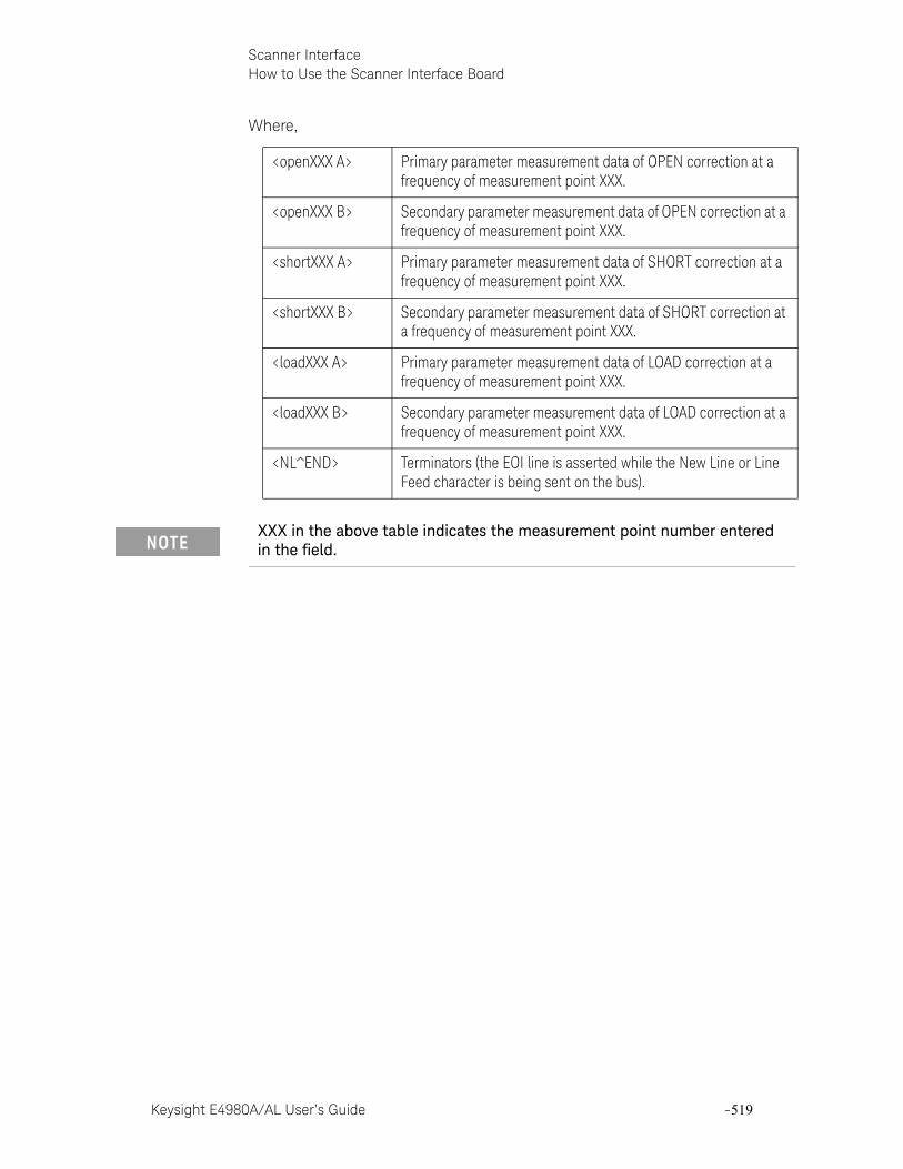
Keysight E4980A/AL User’s Guide -519
Scanner InterfaceHow to Use the Scanner Interface Board
Where,
<openXXX A> Primary parameter measurement data of OPEN correction at a frequency of measurement point XXX.
<openXXX B> Secondary parameter measurement data of OPEN correction at a frequency of measurement point XXX.
<shortXXX A> Primary parameter measurement data of SHORT correction at a frequency of measurement point XXX.
<shortXXX B> Secondary parameter measurement data of SHORT correction at a frequency of measurement point XXX.
<loadXXX A> Primary parameter measurement data of LOAD correction at a frequency of measurement point XXX.
<loadXXX B> Secondary parameter measurement data of LOAD correction at a frequency of measurement point XXX.
<NL^END> Terminators (the EOI line is asserted while the New Line or Line Feed character is being sent on the bus).
XXX in the above table indicates the measurement point number entered in the field.

-520 Keysight E4980A/AL User’s Guide
Scanner InterfaceHow to Use the Scanner Interface Board
-
Keysight E4980A/AL User’s Guide -521
Keysight E4980A/ALPrecision LCR Meter
User’s Guide
G Functional Comparison between 4284A, 4279A and E4980A/AL
This appendix provides a functional comparison between 4284A, 4279A, and E4980A/AL.
Functional Comparison between 4284A, 4279A, and E4980A/ALThe Migration Guide has been provided for a functional comparison between 4284A, 4279A, and E4980A/AL. Refer to the following website.
http://www.keysight.com/find/E4980A/AL/

-522 Keysight E4980A/AL User’s Guide
Functional Comparison between 4284A, 4279A and E4980A/ALFunctional Comparison between 4284A, 4279A, and E4980A/AL
-
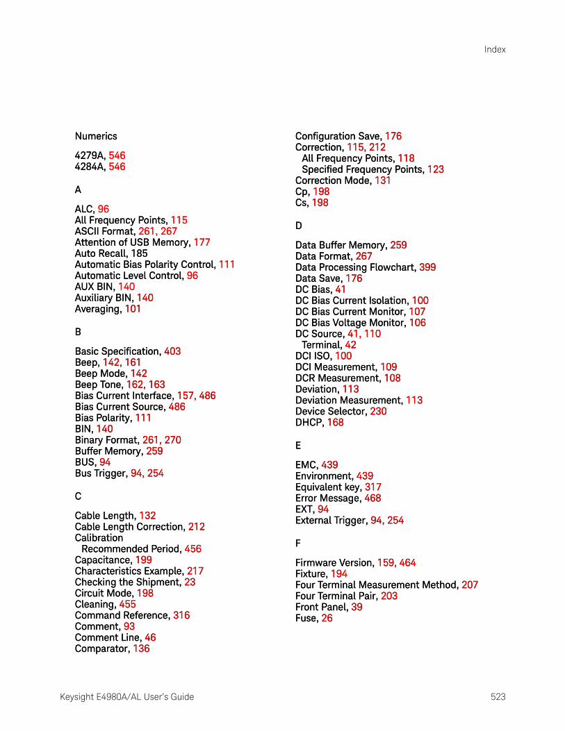
Index
Keysight E4980A/AL User’s Guide 523
Numerics
4279A, 5464284A, 546
A
ALC, 96All Frequency Points, 115ASCII Format, 261, 267Attention of USB Memory, 177Auto Recall, 185Automatic Bias Polarity Control, 111Automatic Level Control, 96AUX BIN, 140Auxiliary BIN, 140Averaging, 101
B
Basic Specification, 403Beep, 142, 161Beep Mode, 142Beep Tone, 162, 163Bias Current Interface, 157, 486Bias Current Source, 486Bias Polarity, 111BIN, 140Binary Format, 261, 270Buffer Memory, 259BUS, 94Bus Trigger, 94, 254
C
Cable Length, 132Cable Length Correction, 212Calibration
Recommended Period, 456Capacitance, 199Characteristics Example, 217Checking the Shipment, 23Circuit Mode, 198Cleaning, 455Command Reference, 316Comment, 93Comment Line, 46Comparator, 136
Configuration Save, 176Correction, 115, 212
All Frequency Points, 118Specified Frequency Points, 123
Correction Mode, 131Cp, 198Cs, 198
D
Data Buffer Memory, 259Data Format, 267Data Processing Flowchart, 399Data Save, 176DC Bias, 41DC Bias Current Isolation, 100DC Bias Current Monitor, 107DC Bias Voltage Monitor, 106DC Source, 41, 110
Terminal, 42DCI ISO, 100DCI Measurement, 109DCR Measurement, 108Deviation, 113Deviation Measurement, 113Device Selector, 230DHCP, 168
E
EMC, 439Environment, 439Equivalent key, 317Error Message, 468EXT, 94External Trigger, 94, 254
F
Firmware Version, 159, 464Fixture, 194Four Terminal Measurement Method, 207Four Terminal Pair, 203Front Panel, 39Fuse, 26
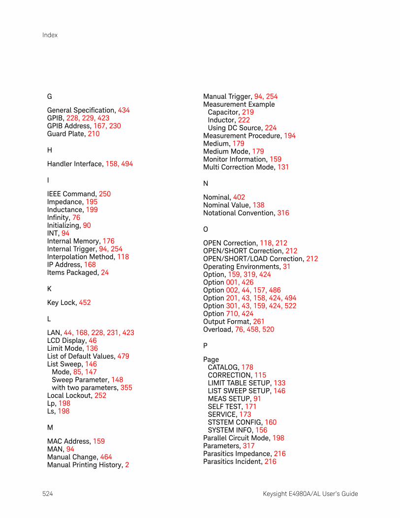
524 Keysight E4980A/AL User’s Guide
Index
G
General Specification, 434GPIB, 228, 229, 423GPIB Address, 167, 230Guard Plate, 210
H
Handler Interface, 158, 494
I
IEEE Command, 250Impedance, 195Inductance, 199Infinity, 76Initializing, 90INT, 94Internal Memory, 176Internal Trigger, 94, 254Interpolation Method, 118IP Address, 168Items Packaged, 24
K
Key Lock, 452
L
LAN, 44, 168, 228, 231, 423LCD Display, 46Limit Mode, 136List of Default Values, 479List Sweep, 146
Mode, 85, 147Sweep Parameter, 148with two parameters, 355
Local Lockout, 252Lp, 198Ls, 198
M
MAC Address, 159MAN, 94Manual Change, 464Manual Printing History, 2
Manual Trigger, 94, 254Measurement Example
Capacitor, 219Inductor, 222Using DC Source, 224
Measurement Procedure, 194Medium, 179Medium Mode, 179Monitor Information, 159Multi Correction Mode, 131
N
Nominal, 402Nominal Value, 138Notational Convention, 316
O
OPEN Correction, 118, 212OPEN/SHORT Correction, 212OPEN/SHORT/LOAD Correction, 212Operating Environments, 31Option, 159, 319, 424Option 001, 426Option 002, 44, 157, 486Option 201, 43, 158, 424, 494Option 301, 43, 159, 424, 522Option 710, 424Output Format, 261Overload, 76, 458, 520
P
PageCATALOG, 178CORRECTION, 115LIMIT TABLE SETUP, 133LIST SWEEP SETUP, 146MEAS SETUP, 91SELF TEST, 171SERVICE, 173STSTEM CONFIG, 160SYSTEM INFO, 156
Parallel Circuit Mode, 198Parameters, 317Parasitics Impedance, 216Parasitics Incident, 216
Index
Keysight E4980A/AL User’s Guide 525
Power Cable, 27Power Supply, 26Power Switch
Turning the Power ON and OFF, 34Preset, 41Product Overview, 38
R
Rear Panel, 43Recall, 176
Auto Recall, 185Recommended Calibration Period, 456Register Number, 180Regular Calibration, 456Remote Control System, 228
GPIB, 229LAN, 231
Remote Mode, 252Replacement, 456Requesting Repair, 456Residual Impedance, 121Resolution
DC Bias, 69Frequency, 64Test Signal Level, 66
Rp, 198Rs, 198
S
Safety, 439Sample Program, 283Save, 176
Measurement Result, 186Screenshot, 191System Information, 174
Save/Recall, 176Instrument Configuration State, 178
Scanner Interface, 159, 522SCPI Command, 250
:ABORt, 321:AMPLitude:ALC, 321:APERture, 321:BIAS:CURRent[:LEVel], 322:BIAS:POLarity:AUTO, 322:BIAS:POLarity:CURRent[:LEVel], 323:BIAS:POLarity:VOLTage[:LEVel], 323
:BIAS:RANGe:AUTO, 323:BIAS:STATe, 324:BIAS:VOLTage[:LEVel], 324:COMParator:ABIN, 325:COMParator:BEEPer, 325:COMParator:BIN:CLEar, 325:COMParator:BIN:COUNt:CLEar, 326:COMParator:BIN:COUNt:DATA, 326:COMParator:BIN:COUNt[:STATe], 326:COMParator:MODE, 326:COMParator:SEQuence:BIN, 327:COMParator:SLIMit, 328:COMParator:SWAP, 328:COMParator:TOLerance:BIN[1-9], 329:COMParator:TOLerance:NOMinal, 329:COMParator[:STATe], 328:CONTrol:CBIas:STATe, 329:CONTrol:HANDler:STATe, 330:CONTrol:SCANner:STATe, 330:CORRection:LENGth, 331:CORRection:LOAD:STATe, 331:CORRection:LOAD:TYPE, 331:CORRection:METHod, 332:CORRection:OPEN:STATe, 333:CORRection:OPEN[:EXECute], 333:CORRection:SHORt:STATe, 333:CORRection:SHORt[:EXECute], 333:CORRection:SPOT[1-201]:FREQuency[:SEL
ected], 334:CORRection:SPOT[1-201]:LOAD:MULTiple:S
TANdard, 334:CORRection:SPOT[1-201]:LOAD:MULTiple[:
EXECute], 334:CORRection:SPOT[1-201]:OPEN:MULTiple[:
EXECute], 335:CORRection:SPOT[1-201]:SHORt:MULTiple[
:EXECute], 335:CORRection:SPOT[1-201]:STATe, 335:CORRection:USE:DATA:SINGle, 337:CORRection:USE:DATA[:MULTi], 336:CORRection:USE[:CHANnel], 336:CURRent[:LEVel], 337:DISPlay:CCLear, 338:DISPlay:ENABle, 338:DISPlay:LINE, 338:DISPlay:PAGE, 339:DISPlay[:WINDow]:TEXT[1-2][:DATA]:FMSD:
DATA, 340
526 Keysight E4980A/AL User’s Guide
Index
:DISPlay[:WINDow]:TEXT[1-2][:DATA]:FMSD[:STATe], 340
:FETCh:SMONitor:IAC, 341:FETCh:SMONitor:IDC, 341:FETCh:SMONitor:VAC, 341:FETCh:SMONitor:VDC, 342:FETCh[:IMPedance]:CORRected, 341:FETCh[:IMPedance][:FORMatted], 341:FORMat:ASCii:LONG, 342:FORMat:BORDer, 342:FORMat[:DATA], 343:FORMat:EXPonent:DIGit, 345:FREQuency[:CW], 345:FUNCtion:DCResistance:RANGe:AUTO, 345:FUNCtion:DCResistance:RANGe[:VALue],
344:FUNCtion:DEV[1-2]:MODE, 344:FUNCtion:DEV[1-2]:REFerence:FILL, 345:FUNCtion:DEV[1-2]:REFerence[:VALue],
345:FUNCtion:IMPedance:RANGe:AUTO, 345:FUNCtion:IMPedance:RANGe[:VALue], 346:FUNCtion:IMPedance[:TYPE], 346:FUNCtion:SMONitor:IAC[:STATe], 347:FUNCtion:SMONitor:IDC[:STATe], 348:FUNCtion:SMONitor:VAC[:STATe], 348:FUNCtion:SMONitor:VDC[:STATe], 349:HCOPy:SDUMp:DATA, 349:INITiate:CONTinuous, 350:INITiate[:IMMediate], 350:LIST:BAND[1-201], 350:LIST:BIAS:CURRent, 351:LIST:BIAS:VOLTage, 351:LIST:CLEar:ALL, 352:LIST:CURRent, 352:LIST:DCSource:VOLTage, 352:LIST:FREQuency, 353:LIST:MODE, 353:LIST:SEQuence:TSTamp:CLEar, 354:LIST:SEQuence:TSTamp:DATA, 354:LIST:STIMulus:DATA, 354:LIST:STIMulus:MDATa, 355:LIST:STIMulus:TYPE, 355:LIST:VOLTage, 356:MEMory:CLEar, 356:MEMory:DIM, 357:MEMory:FILL, 357:MEMory:READ, 357
:MMEMory:DELete[:REGister], 357:MMEMory:LOAD:STATe[:REGister], 358:MMEMory:STORe:STATe[:REGister], 358:OUTPut:DC:ISOLation:LEVel:AUTO, 358:OUTPut:DC:ISOLation:LEVel:VALue, 359:OUTPut:DC:ISOLation[:STATe], 359:OUTPut:HPOWer, 360:SOURce:DCSource:STATe, 360:SOURce:DCSource:VOLTage[:LEVel], 360:STATus:OPERation:CONDition, 361:STATus:OPERation:ENABle, 361:STATus:OPERation[:EVENt], 361:SYSTem:BEEPer:STATe, 362:SYSTem:BEEPer:TONE, 362:SYSTem:BEEPer[:IMMediate], 361:SYSTem:COMMunicate:GPIB[:SELF]:ADDRe
ss, 363:SYSTem:COMMunicate:LAN[:SELF]:ADDRes
s, 363:SYSTem:COMMunicate:LAN[:SELF]:AIP[:ST
ATe], 363:SYSTem:COMMunicate:LAN[:SELF]:CONFig
ure, 364:SYSTem:COMMunicate:LAN[:SELF]:CONTro
l, 364:SYSTem:COMMunicate:LAN[:SELF]:CURRe
nt:ADDRess, 364:SYSTem:COMMunicate:LAN[:SELF]:CURRe
nt:DGATeway, 365:SYSTem:COMMunicate:LAN[:SELF]:CURRe
nt:SMASk, 365:SYSTem:COMMunicate:LAN[:SELF]:DGATe
way, 365:SYSTem:COMMunicate:LAN[:SELF]:DHCP[:
STATe], 365:SYSTem:COMMunicate:LAN[:SELF]:MAC,
366:SYSTem:COMMunicate:LAN[:SELF]:PRESet,
366:SYSTem:COMMunicate:LAN[:SELF]:RESTart
, 366:SYSTem:COMMunicate:LAN[:SELF]:SMASk,
366:SYSTem:DATE, 367:SYSTem:ERRor[:NEXT], 367:SYSTem:KLOCk, 368:SYSTem:PERSona:MANufacturer[:NAME],
371
Index
Keysight E4980A/AL User’s Guide 527
:SYSTem:PERSona:MANufacturer:DEFault, 372
:SYSTem:PRESet, 368:SYSTem:RESTart, 368:SYSTem:TIME, 368:SYSTem:TZONe, 369:TRIGger:DELay, 370:TRIGger:SOURce, 370:TRIGger:TDEL, 371:TRIGger[:IMMediate], 370:VOLTage[:LEVel], 371*CLS, 318*ESE, 318*ESR?, 318*IDN?, 318*LRN?, 319*OPC, 319*OPC?, 319*OPT?, 319*RST, 319*SRE, 320*STB?, 320*TRG, 320*TST?, 320*WAI, 320
ScreenshotSave to controller, 349Save to USB memory, 191
Self Test, 171, 453Sequential Mode, 85, 136, 147Serial Number, 159, 464
Plate, 44, 464Series Circuit Mode, 198Service Mode, 458Service Request, 265Shield, 211SHORT Correction, 121, 212SICL-LAN, 232Single Correction Mode, 131Skip Key, 50Specification, 402
Bias Current Interface, 487Handler Interface, 495Scanner Interface, 523
Specified Frequency Points, 115SRQ, 265Status Byte, 273Status Register, 265
Step Delay Time, 104Step Mode, 85, 147Stray Admittance, 118Supplemental Information, 440Swap Parameter, 134Sweep Mode, 85, 147Syntax, 316System Date, 165System Information, 156
T
Telnet, 237Test Fixture, 212, 488Test Lead, 132, 488Test Signal Level, 201Tolerance Mode, 136Trigger, 94
External, 44Trigger Delay Time, 102Trigger Mode, 94Trigger Source, 254Trigger System, 253Trouble Occurs, 458Two Terminal Measurement Method, 207Typeface Conventions, 6Typical, 402
U
USB, 228, 243, 423USB Address, 159USB Memory, 176USB Port, 244USB Remote Control System, 243Users Guide, 6
V
Varactor Diode, 111
W
Warning Message, 476Warranty Period, 5Web Server, 240

528 Keysight E4980A/AL User’s Guide
Index

This information is subject to change without notice.© Keysight Technologies 2006 - 2019
Edition 16, October 2019
*E4980-90230*E4980-90230
www.keysight.com