Embed Size (px)
Citation preview

KEY DISTRIBUTION AND DISTRIBUTED
INTRUSION DETECTION SYSTEM
IN
WIRELESS SENSOR NETWORK
A thesis submitted in fulfillment of the requirements
for the degree of doctor of philosophy
Piya Techateerawat
School of Electrical and Computer Systems Engineering
Science, Engineering and Technology Portfolio
RMIT University
July 2007

ii
DECLARATION
I certify that except where due acknowledgement has been made, the work is that of the
author alone; the work has not been submitted previously, in whole or in part, to qualify
for any other academic award; the content of the thesis is the result of work which has
been carried out since the official commencement date of the approved research program;
and, any editorial work, paid or unpaid, carried out by a third party is acknowledged.
__________________________
( Piya Techateerawat )
_______/________ / _________

iii
ACKNOWLEDGEMENT
To complete this thesis, many people provided support and contributed their
efforts to the work. I would like to thank all staff and research students in the Engineering
Department, RMIT University. Their support and insight was invaluable. Extra thanks to
Prof. Andrew Jennings for delightful supervision and support especially under critical
circumstances. I also would like to thank Dr. Jidong Wang as a second supervisor for a
warm association.
Other thanks to Joseph So and Daud Channa who always provided research tips
and suggestions. I also would like to thank Pichaporn Tangtrongjetana for day-to-day
support as well as Ayako Matsui and David Bell for proofreading.
Finally, my family is a major source of energy to get through the difficult process
of completing this thesis. I would like to express thanks to my father, mother and two
sisters.

iv
PUBLICATIONS
1.) P. Techateerawat and A. Jennings, “Energy efficiency of Intrusion detection
systems in wireless sensor network”, in 2006 First International Workshop
Intelligent Agents in Wireless Sensor Networks (IA-WSN), Hong Kong, Dec 18-22,
2006, pp. 227-230. (http://cs.acadiau.ca/~eshakshu/IA-WSN-2006.htm) Related to
chapter 4 and 5.
2.) P. Techateerawat and A. Jennings, “Hint Key Distribution for Sensor Networks”,
in International Joint Conferences on Computer, Information, and Systems
Sciences, and Engineering (CISSE 2006), Online conference, 2006.
(http://www.cisse2006.org/) Related to chapter 4.
3.) P. Techateerawat and A. Jennings, “Analyzing the Key Distribution from Security
Attacks in Wireless Sensor”, in International Joint Conferences on Computer,
Information, and Systems Sciences, and Engineering (CISSE 2006), Online
conference, 2006. (http://www.cisse2006.org/) Related to chapter 5.
4.) P. Techateerawat and A. Jennings, “Adaptive Intrusion Detection in Wireless
Sensor Networks”, accepted at The 2007 International Conference on Intelligent
Pervasive Computing (IPC-07), Jeju Island, Korea, Oct 11-13, 2007.
(http://www.sersc.org/IPC2007/) Related to chapter 4 and 5.

v
TABLE OF CONTENTS
DECLARATION ....................................................................................................................... ii
ACKNOWLEDGEMENT......................................................................................................... iii
PUBLICATIONS.......................................................................................................................iv
TABLE OF CONTENTS ............................................................................................................v
LIST OF FIGURES ................................................................................................................ viii
LIST OF TABLES......................................................................................................................x
ABSTRACT ...............................................................................................................................1
Chapter 1. Introduction............................................................................................................2
1.1 Wireless Sensor Network ................................................................................................2
1.2 Security...........................................................................................................................3
1.3 Proposed Solution ...........................................................................................................3
1.4 Contribution....................................................................................................................4
1.5 Thesis Structure...............................................................................................................4
Chapter 2. Background............................................................................................................6
2.1 Wireless Sensor Network ................................................................................................6
2.1.1 Ease of Installation.............................................................................................7
2.1.2 Large Coverage Area .........................................................................................7
2.1.3 Unattended System ............................................................................................8
2.1.4 Long Battery Life...............................................................................................8
2.1.5 Wireless Communication .................................................................................10
2.1.6 Sensor..............................................................................................................12
2.1.7 Operating System.............................................................................................13
2.1.8 Differentiated from Ad Hoc Networks..............................................................14
2.2 Security.........................................................................................................................15
2.2.1 Security Definition...........................................................................................15
2.2.2 Cryptography ...................................................................................................16
2.2.3 Attacks in Wireless Networks...........................................................................21
2.2.4 Attacks on Encryption......................................................................................24
2.2.5 Intrusion Detection System ..............................................................................25

vi
Chapter 3. Literature Survey..................................................................................................28
3.1 Cryptographic Issues in Sensor Network........................................................................29
3.2 Key Management ..........................................................................................................30
3.2.1 Efficient Large-Group Key Distribution (ELK) ................................................32
3.2.2 Security Protocols for Sensor Networks (SPINS)..............................................33
3.3 Intrusion Detection System............................................................................................36
3.3.1 Agent-based IDS..............................................................................................37
3.4 Conclusion ....................................................................................................................38
Chapter 4. Hint Key Distribution & Adaptive IDS.................................................................40
4.1 Hint Key Distribution (HKD) ........................................................................................41
4.1.1 Overview .........................................................................................................41
4.1.2 Mechanism ......................................................................................................41
4.1.3 Implementation ................................................................................................42
4.1.4 Features ...........................................................................................................47
4.2 Adaptive Intrusion Detection System (Adaptive IDS) ....................................................48
4.2.1 Overview .........................................................................................................48
4.2.2 Mechanism ......................................................................................................49
4.2.3 Implementation ................................................................................................51
4.2.4 Features ...........................................................................................................52
4.3 Cooperation between HKD and Adaptive IDS ...............................................................53
4.3.1 Overview .........................................................................................................53
4.3.2 Mechanism ......................................................................................................54
4.3.3 Implementation ................................................................................................56
4.4 Conclusion ....................................................................................................................57
Chapter 5. Evaluation............................................................................................................59
5.1 Hint Key Distribution (HKD) Evaluation.......................................................................60
5.1.1 Metrics of Performance ....................................................................................60
5.1.2 Parameters of Evaluation..................................................................................60
5.1.3 Evaluation Scenario .........................................................................................61
5.1.4 Performance Model..........................................................................................64
5.1.5 Evaluation........................................................................................................67

vii
5.2 Adaptive Intrusion Detection System Evaluation ...........................................................74
5.2.1 Metrics of Performance ....................................................................................74
5.2.2 Parameters of Evaluation..................................................................................75
5.2.3 Evaluation Scenario .........................................................................................76
5.2.4 Performance Model..........................................................................................79
5.2.5 Evaluation........................................................................................................82
5.3 Cooperation between HKD and Adaptive IDS ...............................................................89
5.3.1 Metrics of Performance ....................................................................................89
5.3.2 Parameters of Evaluation..................................................................................90
5.3.3 Evaluation Scenario .........................................................................................90
5.3.4 Performance Model..........................................................................................91
5.3.5 Evaluation........................................................................................................91
5.4 Conclusion ....................................................................................................................95
Chapter 6. Conclusion and Future Work ................................................................................97
6.1 Chapter One (Introduction)............................................................................................98
6.2 Chapter Two (Background) ...........................................................................................98
6.3 Chapter Three (Literature Survey) .................................................................................98
6.4 Chapter Four (Hint Key Distribution & Adaptive IDS) ..................................................99
6.5 Chapter Five (Evaluation)............................................................................................100
6.6 Future Work................................................................................................................101
REFERENCES .......................................................................................................................103

viii
LIST OF FIGURES
Figure 2.1 Wireless Sensor Mica2 node. ............................................................................ 7
Figure 2.2 Radio processing procedure in receiving a packet for wireless sensor devices.
......................................................................................................................... 12
Figure 2.3 Comparison of sensor network operating system [34]. ................................... 13
Figure 2.4 Security threats of data and systems................................................................ 16
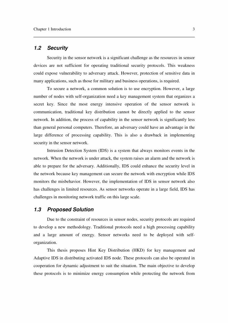
Figure 2.5 Encryption process .......................................................................................... 17
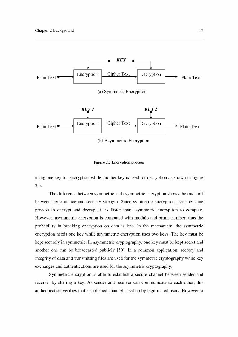
Figure 2.6 The function of DES [52]. ............................................................................... 19
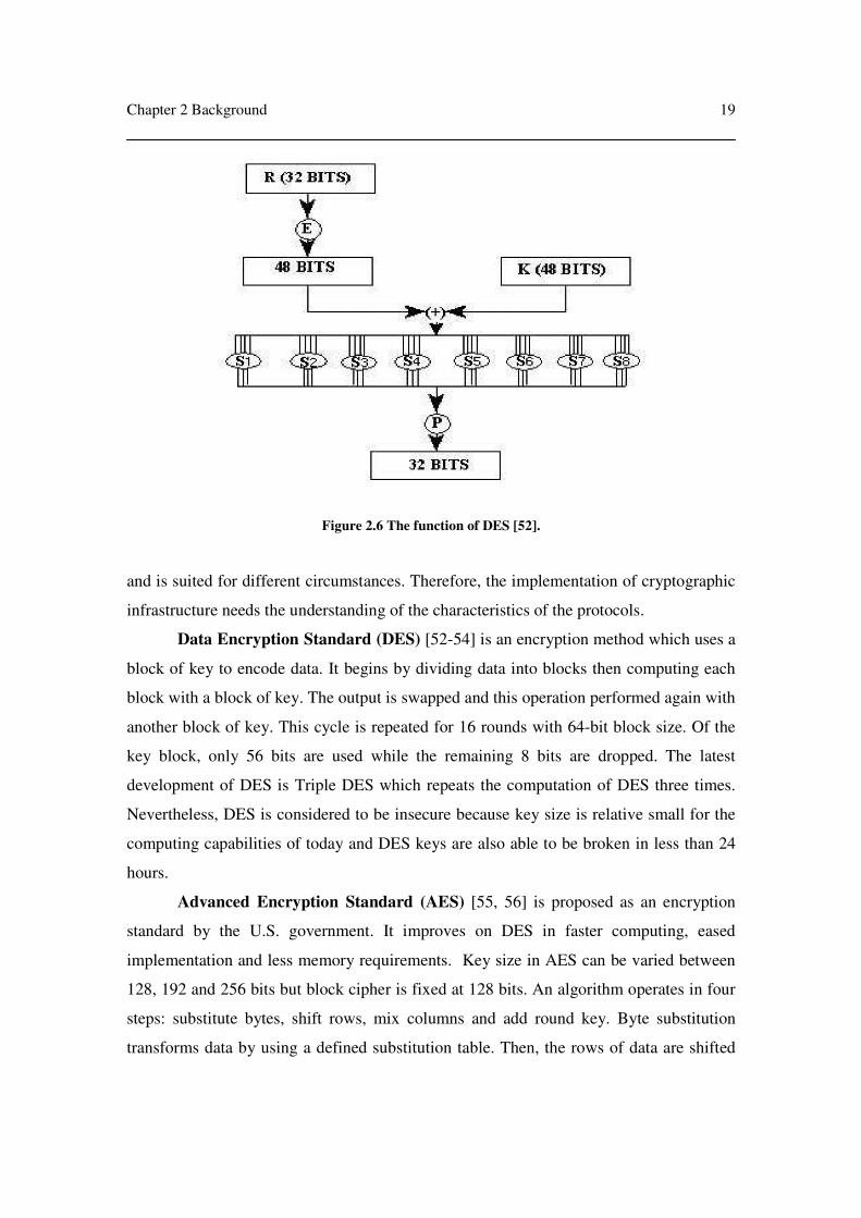
Figure 2.7 AES Encryption (Left) and AES Decryption (Right) [57]. ............................. 20
Figure 2.8 Shared secret key derived from private and public key. ................................. 21
Figure 2.9 Data interception in Man-in-the-Middle Attack.............................................. 22
Figure 2.10 Three way handshake in TCP........................................................................ 23
Figure 2.11 Procedures of Intrusion Detection System .................................................... 26
Figure 3.1 Hierarchical key tree in ELK [94]. ................................................................. 33
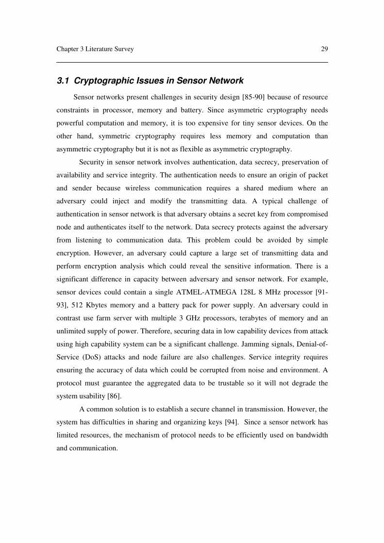
Figure 3.2 Counter exchange mechanism in SNEP. ......................................................... 34
Figure 3.3 Key chain in µTESLA..................................................................................... 36
Figure 3.4 Agent-based IDS where grey node activates IDS [128].................................. 38
Figure 4.1 Procedure to find current key KC from master key KM ................................... 42
Figure 4.2 Generating hint procedure in HKD ................................................................. 43
Figure 4.3 Receiver procedure in HKD ............................................................................ 44
Figure 4.4 Hint message structure. ................................................................................... 45
Figure 4.5 Keys stored in memory.................................................................................... 46
Figure 4.6 Voting procedure in Adaptive IDS.................................................................. 50
Figure 4.7 Clock adjusting procedure in Adaptive IDS.................................................... 51
Figure 4.8 Exchange information procedure for Adaptive IDS........................................ 54
Figure 4.9 To distinguish activities of HKD in IDS activated node. ................................ 55
Figure 4.10 Informing current key management from HKD to IDS activated nodes....... 56
Figure 5.1 GUI of Prowler software [143]........................................................................ 62
Figure 5.2 Example of source code in Prowler [143]. ...................................................... 63
Figure 5.3 Logarithm of computation times for current key in brute force attack. ......... 67

ix
Figure 5.4 Logarithm of computation times for the key chain in brute force attack. ...... 68
Figure 5.5 Nodes deployment in the simulation. .............................................................. 75
Figure 5.6 An example source code of sine wave [145]................................................... 76
Figure 5.7 GUI of Ptolemy software [145]. ...................................................................... 77
Figure 5.8 Hierarchical abstraction in Ptolemy [145]....................................................... 78
Figure 5.9 Core defense model. ........................................................................................ 80
Figure 5.10 Boundary defense model. .............................................................................. 81
Figure 5.11 Pattern of how spreading activated node in the cluster (a) Pattern in Adaptive
IDS .................................................................................................................. 85
Figure 5.12 Performance of Adaptive IDS. ...................................................................... 86
Figure 5.13 (a) shows number of message involved in distributing activated nodes of
three protocols against Adaptive IDS in (b). (c) shows ratio of number of
activated nodes in three protocols versus Adaptive IDS in (d)....................... 88
Figure 5.14 Comparing a system lifetime between cooperative protocol and individual
HKD................................................................................................................ 92
Figure 5.15 Graphs shows transmitted messages in (a) individual Adaptive IDS............ 93

x
LIST OF TABLES
Table 2.1 Power consumption in Medusa II nodes [21]. .................................................. 10
Table 5.1 Energy cost in SPINS [111].............................................................................. 65
Table 5.2 Security features in each protocol..................................................................... 70
Table 5.3 Energy consumption in communication for each protocol. .............................. 71
Table 5.4 Energy saving feature in each protocol............................................................. 73
Table 5.5 Efficiency in detecting attack for each distribution strategy. ........................... 84

1
ABSTRACT
This thesis proposes a security solution in key management and Intrusion
Detection System (IDS) for wireless sensor networks. It addresses challenges of
designing in energy and security requirement. Since wireless communication consumes
the most energy in sensor network, transmissions must be used efficiently. We propose
Hint Key Distribution (HKD) for key management and Adaptive IDS for distributing
activated IDS nodes and cooperative operation of these two protocols.
HKD protocol focuses on the challenges of energy, computation and security. It
uses a hint message and key chain to consume less energy while self-generating key can
secure the secret key. It is a proposed solution to key distribution in sensor networks.
Adaptive IDS uses threshold and voting algorithm to distribute IDS through the
network. An elected node is activated IDS to monitor its network and neighbors. A
threshold is used as a solution to reduce number of repeated activations of the same node.
We attempt to distribute the energy use equally across the network.
In a cooperative protocol, HKD and Adaptive IDS exchange information in order
to adjust to the current situation. The level of alert controls the nature of the interaction
between the two protocols.

2
Chapter 1. Introduction
1.1 Wireless Sensor Network
Sensor networks have been developing rapidly in recent years and their
deployment is an advantage for new applications. Sensor networks are an innovation
combining wireless communication, sensing features and embedded technology. Sensor
devices also support self-organization and long periods of operation e.g. 1-5 years.
Limitations of the sensor network are a constraint in battery capacity, processing
power and memory because effortless deployment requires a small size device. In
addition, the sensor network is designed to operate as a group (or cluster) with a large
number of nodes, thus the cost of each node should be kept to a minimum. Therefore,
CPU, memory and battery capacity are limited.
Chapter 1 Introduction
3
1.2 Security
Security in the sensor network is a significant challenge as the resources in sensor
devices are not sufficient for operating traditional security protocols. This weakness
could expose vulnerability to adversary attack. However, protection of sensitive data in
many applications, such as those for military and business operations, is required.
To secure a network, a common solution is to use encryption. However, a large
number of nodes with self-organization need a key management system that organizes a
secret key. Since the most energy intensive operation of the sensor network is
communication, traditional key distribution cannot be directly applied to the sensor
network. In addition, the process of capability in the sensor network is significantly less
than general personal computers. Therefore, an adversary could have an advantage in the
large difference of processing capability. This is also a drawback in implementing
security in the sensor network.
Intrusion Detection System (IDS) is a system that always monitors events in the
network. When the network is under attack, the system raises an alarm and the network is
able to prepare for the adversary. Additionally, IDS could enhance the security level in
the network because key management can secure the network with encryption while IDS
monitors the misbehavior. However, the implementation of IDS in sensor network also
has challenges in limited resources. As sensor networks operate in a large field, IDS has
challenges in monitoring network traffic on this large scale.
1.3 Proposed Solution
Due to the constraint of resources in sensor nodes, security protocols are required
to develop a new methodology. Traditional protocols need a high processing capability
and a large amount of energy. Sensor networks need to be deployed with self-
organization.
This thesis proposes Hint Key Distribution (HKD) for key management and
Adaptive IDS in distributing activated IDS node. These protocols can also be operated in
cooperation for dynamic adjustment to suit the situation. The main objective to develop
these protocols is to minimize energy consumption while protecting the network from

Chapter 1 Introduction
4
common attacks in general use. In Adaptive IDS, energy consumption is expected to be
distributed across the entire network, and the total energy consumption in the network is
also expected to be used in the most efficient way.
1.4 Contribution
The first contribution of this thesis is the design and implementation of HKD,
Adaptive IDS and cooperative operation between HKD and Adaptive IDS. The design of
these protocols indicates the limitation of energy, computation and security. The second
contribution is a design of an evaluation method to verify security and resource usage in
sensor network. The third contribution is an analysis of our proposed protocols. Our
studies show that HKD can enhance the system lifetime while security strength is
equivalent to existing protocols. Adaptive IDS expands coverage area while energy
consumption is distributed through the network. In cooperative protocols, the operation
could adjust the security level according to the situation, but it consumes more energy
than non-cooperative protocol.
1.5 Thesis Structure
The remainder of this thesis is organized as follows.
Chapter 2 explains features of sensor network, the definition of security, how
intrusion detection system operates in the case of attacks in network.
Chapter 3 discusses existing cryptography, key management protocol and
intrusion detection system protocol from researchers’ points of view.
Chapter 4 introduces our proposed solutions for security in sensor network. Our
HKD uses hint message to reduce the amount of energy consumption and avoid exposing
an actual key. A key and key chain is generated in each node from pre-installed master
key. Our Adaptive IDS uses voting algorithm and threshold to elect activated IDS node.
The threshold can reduce the number of repetitions of activation of the same node, so
energy consumption is distributed across the network. In cooperative protocol,
information is exchanged for dynamic adjustment to suit different situations.
Chapter 5 evaluates and analyzes our HKD, Adaptive IDS and cooperative
protocol. HKD reduces the amount of energy consumption more effectively than other

Chapter 1 Introduction
5
protocols while it can protect the network from common attacks. Adaptive IDS can
distribute selected node with repeated activation of the same node being reduced. In
cooperative protocol, security can be its strength, and a safe scenario consumes less
energy than non-cooperative protocols. However, in general this will consume more
energy.
Chapter 6 concludes our work and suggests future work in sensor network
security.

6
Chapter 2. Background
2.1 Wireless Sensor Network
Investigation of wireless sensor network has been increasing in recent years [1-6].
A vision for sensor network is a large number of nodes deployed in a large field. Every
node establishes the routine of network and communication without support of existing
infrastructure. Sensor network is expected to operate for many years without human
maintenance. It is also presumed to be self managing in nodes joining, leaving and node
failure. As a result, wireless sensor network faces new challenges [7].

Chapter 2 Background
7
2.1.1 Ease of Installation
Ease of installation is a crucial requirement in sensor networks since a location
cannot be assumed to have an existing infrastructure. For instance, sites installed with
sensor network can range from buildings to rivers in the forest. Therefore, each node
must be operated as a complete unit that is equipped with necessary components
including power source, computing unit, communication unit, data storage and sensor. In
addition, size of each node should be small because large node size is difficult to deploy.
Furthermore, the large node size raises issues of security, inconvenience in transportation
and impact on the environment. For example, figure 2.1 shows Mica2 node [8, 9] which
size is only 58 mm x 32 mm x 7 mm but contains processor, memory, wireless radio and
battery, so each node can operate as a complete unit. Consequently, Mica2 can easily be
deployed in the field and does not require external infrastructure to operate as a sensor
node.
2.1.2 Large Coverage Area
Large coverage area is a major feature of sensor networks which assists in
collecting data from the field. It requires a large number of nodes in a system, usually
Figure 2.1 Wireless Sensor Mica2 node.

Chapter 2 Background
8
hundreds or thousands. For example, forest monitoring may need thousands of nodes to
observe and collect data. These sensor nodes also need to be deployed over the forest. In
[10], it is supported that such large number of nodes in the field improves sensor network
operation in a wide area, which also enhances battery lifetime.
Furthermore, coverage is also a quality benchmark of sensor networks. Since data
collection depends on the range, location and density of sensor nodes, coverage is an
important aspect to observe data. This coverage benchmark could be graded from the best
to the worst in support path which represents how well communication path is working.
The support path calculates the number of possible paths in the cluster and determines the
number of support nodes along the path. The best coverage contains the largest number
of support nodes in the path while the worst coverage contains the least number of
support nodes. The larger number of support nodes also assists in energy savings in
multi-hop routing and redundancy in the event of node failure.
2.1.3 Unattended System
Unattended system is one of the goals in sensor network design. In large scale,
test and maintenance of each specific node is not an efficient method. For example, if a
cluster that contains ten thousands nodes conducts maintenance of ten percent of nodes
every month, administration would need to deal with a thousand nodes monthly. To avoid
excessive maintenance, sensor networks should be operated as an unattended system
[11].
2.1.4 Long Battery Life
Long battery life is a crucial factor in sensor networks because it is impractical to
replace battery in each node after the deployment. Furthermore, sensor network is
operating as an unattended system so an equipped energy source is expected to operate
for years. Consequently, energy consumption in sensor nodes needs to be minimized to
enhance the battery lifetime. In general, wireless communication consumes most energy
in sensor nodes [1, 10-12]. To extend the battery lifetime, it is necessary to minimize the
amount of output transmit power and the frequency of messages. Since sensor networks
consist of a large number of nodes deployed in the area, energy in communication can be
optimized by using multi hop routing [13-17]. Instead of transmitting a message over a

Chapter 2 Background
9
long range, message can be passed through others nodes located between sender and
receiver. In addition, sleep mode can improve the operation lifetime because the amount
of energy could be reduced by switching the system to sleep mode when the system is
idle [18].
Sleep mode is an energy saving state which turns off wireless radio and non-
essential components. In sensor network, there is a period in which system does not
perform computation, transmission and reception of data. Therefore, as shown in table
2.1, battery lifetime can significantly be increased by the use of sleep mode which turns
off components in the system. Yet, during the sleep mode, sensor nodes cannot send and
receive any data. This could result in a failure of the reception of transmission of data.
Therefore, during the use of sleep mode, it is essential to keep a balance between energy
to be saved and the system operation. Otherwise, overall performance could fail due to
the difficulty in communication. Currently, there are a number of protocols to manage
sleep mode [18-22]. For example, SPAN protocol [14] manages sleep mode for a specific
area. As in a dense area only a few nodes need to wake up and prepare for receiving data,
which enables others to use the sleep mode. This protocol shows the effectiveness of a
balance between energy and performance.
To design sensor networks, it is essential to consider battery characteristics.
Considering the capacity of battery, the battery cannot be fully used due to the energy
extracted via chemistry [21, 23-25]. For example, a 1500 mAh battery is estimated to
provide 15 mA for 100 hours, but in practice the amount will be less than the estimated
amount. In addition, Alkaline AA-battery would not be constantly discharged at 1.5 V,
but it drops to nearly 1.2 V in its half-life. Likewise, the voltage of Lithium battery drops
sharply when the battery is nearly empty although the battery provides more constant
voltage than others.
Alternatively, solar cell panels can be used to supply energy. This strategy lets the
sensor node absorb solar energy in daylight as well as use excess energy to recharge the
battery. In solar energy supply [2, 26-28], solar cells show different characteristics from
battery and behaves as a voltage limited current source. When incident solar radiation
decreases, the current decreases. As a result, energy output is unstable and requires a
battery to stabilize the voltage.

Chapter 2 Background
10
2.1.5 Wireless Communication
Wireless communication is used to exchange information between nodes and base
station. While sensor networks have a main objective, to collect sensor data from the
field, data transmission via a wire is impractical because of coverage area and
installation. It can be said that wireless communication is the solution for data exchange.
Sensor networks involve many data transmissions as base stations use the communication
for requesting data, organizing the network and maintaining security. Sensor nodes also
use communication for routing paths, exchanging information among nodes and
responding to the base station. For example, Mica2 [8, 9, 29, 30] is equipped with
868/916 MHz Multi-Channel Radio Transceiver.
To handle a transmission packet, the system needs to interact with network Media
Access Control (MAC). It manages a radio signal, amplitude shifting, background noise
Table 2.1 Power consumption in Medusa II nodes [21].

Chapter 2 Background
11
and delay. When receiving a packet, radio signal is transmitted from RF transceiver to
radio control system which processes and encapsulates a packet following the protocol
standard. Then, information is passed to the application for further use as shown in Figure
2.2. In contrast, the process of sending a packet is conducted in reverse order to packet
receiving. As there are many processing steps, jitter may affect the application. However,
normally transmission delay is greater than processing delay. These procedures in low
level protocols are abstracted from the application layer so application developers are not
required to organize this process [31].
MAC Protocol of sensor networks is differentiated from other wireless networks
in that it must create a network infrastructure among a large number of nodes and share
resources efficiently among these nodes. This is an important issue in order to extend the
operating lifetime of sensor networks. There are two major techniques which are
implemented in MAC protocols. The first technique is Frequency Division Multiple
Access (FDMA) that transmits data over many channels although most FDMA protocols
consume more energy to organize channels and transmit over multiple channels. The
second technique is Time Division Multiple Access (TDMA) that transmits data on a
single channel and organizes each transmission by allocating a time frame. Although both
FDMA and TDMA have been adjusting to meet the requirement in sensor networks,
many researchers favor TDMA. This is because the nature of TDMA, which has low
power consumption, can be an advantage for sensor networks. A communication slot also
can be arranged for each node so it minimizes collisions in transmitting. In addition,
TDMA supports low-duty cycle operation because sensor nodes only need to turn on the
radio to assigned channel [18]. For example, Eyes MAC protocol for Sensor network
(EMACs) [14] is a self organizing network based on TDMA protocol. It can transmit data
to the base station without data routing. EMACs also manage TDMA slots by the
division of time frame into three periods; a communication request period to initiate the
communication, a traffic control period to organize transmission channel, and a data
period to transmit data. Moreover, there is research attempting to develop hybrid
TDMA/FDMA [32]. Since hybrid TDMA/FDMA can switch between TDMA and
FDMA, TDMA is used when the sender consumes more power, so this means that idle
channels can be turned off to reduce energy consumption. FDMA can be used when the

Chapter 2 Background
12
receiver consumes more power than the sender which decreases power on synchronizing
during the transmissions [32].
A control mechanism when a packet is sent and received is organized by carrier
sense. There are two major techniques: Carrier Sense Multiple Access with Collision
Detection (CSMA/CD) and Carrier Sense Multiple Access with Collision Avoidance
(CSMA/CA). CSMA/CD mechanism attempts to transmit data immediately. If a
collision is detected, it backs off for a random period before re-transmitting. CSMA/CA
applies handshake mechanism to avoid a collision. In the handshake, the sender transmits
Request-to-Send (RTS) and waits for Clear-to-Send (CTS) from the receiver before
starting transmission. Since this handshake is very short, the performance is significantly
improved [18].
2.1.6 Sensor
Sensor is a component interpreting analogue signal to digital signal. This capability
can be used to measure environment data and transmit to the system. Previously, there
were issues regarding sensors in interfaces between the sensor and the system, and
restrictions of power supply and data transfer. Since digital sensors have been introduced,
the stack of the sensor is abstracted for the developer and is well integrated with the
system. Currently, sensors have dramatically improved in terms of accuracy, power
consumption and size. There are many types of sensors such as light, temperature,
pressure, magnetic, vibration and humidity sensors. Therefore, a number of applications
can select the proper sensor to meet their requirements. For instance, Analog Devices
Figure 2.2 Radio processing procedure in receiving a packet for wireless sensor devices.
Radio Signal
RF transceiver Radio Control Application Processor

Chapter 2 Background
13
AD7418 [33] is temperature sensor containing analogue-to-digital converter chip as well
as an interface protocol.
2.1.7 Operating System
An operating system in sensor network is required for the effective management
of the hardware capabilities while it is also necessary to support concurrency-intensive
operation in a manner that achieves efficient modularity and robustness [33]. Efficient
management handles processor, memory, wireless communication and battery. The
software also needs to organize the resource for multithread access which is
simultaneously used in some circumstances. With these restrictions, many systems design
proprietary operating systems and architecture for particular applications. For instance,
TinyOS [35, 36] is widely used by developers and researchers. TinyOS is a lightweight
operating system which supports a limited resource device. In addition, it is coordinated
with wireless network infrastructure. Although TinyOS needs to be modified for specific
Figure 2.3 Comparison of sensor network operating system [34].

Chapter 2 Background
14
systems, it is one of the most efficient operating systems in embedded systems.
Moreover, there are other operating systems which are designed for sensor network such
as Contiki [37], Nano-RK [38], SOS [39], MANTIS [40] and Nano-Qplus [34] which are
shown in figure 2.3. To compare with each of the others, TinyOS is based on event-
driven execution and focuses on power management. It also provides flexibility on
scheduling to support unpredictable events in sensor network. SOS has an objective in
achieving dynamic reprogramming as well as updating a joining node. MANTIS and
Nano-Qplus add real-time scheduling to support time-sensitive task. However, Nano-
Qplus has an advantage in consuming less power and task latency.
2.1.8 Differentiated from Ad Hoc Networks
As embedded technology has been improved, many wireless network protocols
have become more popular although the number of protocols confuses the community.
As an example, mobile ad hoc network has a similar function to the wireless sensor
networks in terms of embedded system, mobile devices and wireless communication.
However, it focuses on mobility, in which nodes are able to move randomly as well as
their routers. This applies in communication among vehicles and stations [41]. To
compare with sensor networks, the ad hoc protocol has more capabilities in higher data
rate, lower packet drop rate and less overhead in mobility communication. In general,
sensor networks transmit data rates in the order of kilobytes per second compared with
megabytes per second in ad hoc network [42]. Additionally, ad hoc protocol requires
more performance, bandwidth and energy supply than sensor networks. The ad hoc
architecture is also different in operation lifetime, sleep mode, resource and cost because
sensor network uses a large number of nodes so each node must be relatively cheap
which is in opposition to ad hoc node. The battery lifetime in ad hoc protocol is not
regarded as an issue since it always has a supply of power from infrastructure. Although
it looks similar in terms of wireless communication to sensor network, the ad hoc usage
of resources is different.

Chapter 2 Background
15
2.2 Security
Fundamentally, security concerns three aspects: confidentiality, integrity and
availability. It also covers four threats: interruption, interception, modification and
fabrication [43]. In addition, cryptography is a mathematical method that provides a
mechanism to secure data. Network and software security determine different
vulnerabilities in particular systems. Hence, security software must organize proper
security control for specific systems [44].
2.2.1 Security Definition
Security can be defined as the management of risk which entails confidentiality,
integrity and availability. Firstly, confidentiality is concerned with only allowing
authorized users to access systems and information, and secondly integrity is concerned
with only letting authorized users modify the information and systems. Lastly,
availability is concerned with allowing authorized users to access the information and
systems when needed. This availability can be indicated by capacity of service, waiting
time, fault tolerance and level of concurrency. A common crisis of availability is the
denial of service attack. Therefore, consideration of these three security aspects is
essential, and they are related to each other [44, 45].
To develop security applications, this thesis must address a variety of threats. A
threat is a circumstance in which data or systems have potential to be under attack. It also
can be the result of human error and failure of software design. Threats from adversary
can be in different forms, and these can be categorized into four forms: interception,
interruption, modification and fabrication [46] as shown in figure 2.4. Interception is a
situation that an unauthorized user gains access to system. In passive mode, the
interceptor may not leave any sign or evidence so the system could find it difficult to
detect the threat. Interruption is a circumstance that systems or data are unusable. For
example, an attacker erases data and destroys system files so system and data cannot be
operated properly. Modification threat is a situation where an unauthorized user changes
data, alters programs and modifies hardware components. Most of these threats could be
easily detected by integrity techniques, yet many challenges remain difficult to detect.

Chapter 2 Background
16
Fabrication is a circumstance where an unauthorized user inserts imitation transactions to
a network which may add or change an existing database. These are four fundamental
threats which must be included in security objectives [44].
2.2.2 Cryptography
Cryptography is a process of applying mathematic calculation to maintain secrecy
of data. It uses encryption and decryption to hide data from unauthorized users. Original
data or plaintext is converted to encrypted data or cipher text in the process. The cipher
text can only be decrypted by predefined password or key. To consider the four security
threats, encryption delivers a solution for interception, interruption, modification and
fabrication. For interception, encryption prevents unauthorized users from reading or
listening to data. For interruption threat, encryption prevents the other parties so that only
authorized users are allowed to access the data. For modification threat, encryption could
secure data by detecting violation of data integrity. For fabrication threat, authentication
could manage and validate the authorized users. Therefore, encryption is one of the
solutions to secure data in an insecure environment [47, 48].
Both encryption and decryption require a password or key to secure data which
allows only authorized users to access [49]. In symmetric encryption, encryption and
decryption use the same key. However, asymmetric encryption uses a pair of keys by
Figure 2.4 Security threats of data and systems.
Data and Systems
Interruption
Fabrication
Modification
Interception
Chapter 2 Background
17
using one key for encryption while another key is used for decryption as shown in figure
2.5.
The difference between symmetric and asymmetric encryption shows the trade off
between performance and security strength. Since symmetric encryption uses the same
process to encrypt and decrypt, it is faster than asymmetric encryption to compute.
However, asymmetric encryption is computed with modulo and prime number, thus the
probability in breaking encryption on data is less. In the mechanism, the symmetric
encryption needs one key while asymmetric encryption uses two keys. The key must be
kept securely in symmetric. In asymmetric cryptography, one key must be kept secret and
another one can be broadcasted publicly [50]. In a common application, secrecy and
integrity of data and transmitting files are used for the symmetric cryptography while key
exchanges and authentications are used for the asymmetric cryptography.
Symmetric encryption is able to establish a secure channel between sender and
receiver by sharing a key. As sender and receiver can communicate to each other, this
authentication verifies that established channel is set up by legitimated users. However, a
Figure 2.5 Encryption process
Cipher Text
Encryption Decryption
Encryption Decryption
Plain Text
Plain Text Plain Text
Cipher Text
KEY 1 KEY 2
KEY
(a) Symmetric Encryption
(b) Asymmetric Encryption
Plain Text

Chapter 2 Background
18
network has many users requiring secure channels, thus using a separated key in each
channel would not be convenient. Therefore, asymmetric encryption could provide a
solution by preparing the pair of keys for every user. The fist key is a private key kept
secretly by the user, and another key is a public key which other users could obtain.
Therefore, each user requires only a pair of keys to communicate with the others.
Nowadays, encryption systems combine both symmetric and asymmetric as one
system to enhance the security. For example, Pretty Good Privacy (PGP) [51] is a
security scheme using both symmetric encryption and asymmetric encryption. The
process of PGP mechanism begins with the generation of a symmetric key for sender, and
after that receiver’s public key is used to encrypt this symmetric key. Next, sender sends
this encrypted message to receiver, and due to this process the receiver can decrypt the
message with receiver’s private key. After that, the receiver can obtain the symmetric key
from the message and is then ready to establish a secure channel. In a large network,
every user has different keys, so it is necessary to organize the keys as a part of key
management. In key management, key distribution is required to exchange the keys
among the network.
Key distribution is a method used to share secret keys among the parties before
establishing a secure transmission. In symmetric key cryptography, both parties have a
secret key which must be exchanged prior to the establishment of a secure channel. In
asymmetric key cryptography, the public key is used to exchange and set up a secure
channel without exposing the private key. In addition, setting up a secure channel could
use shared secrets such as a random number and second key for authentication. In sensor
network, key distribution generally places secret keys in the nodes before deployment.
So, every node has an initiated key to establish a secure channel [50]. This method can be
called key pre-distribution. However, systems still require a method of exchanging and
updating keys among the nodes. Thus, keys need a secure tunnel for delivery in the
networks. Generally, the public key can be used to establish a tunnel in order to exchange
keys later on. However, many systems do not have the capability to operate public key so
they need to use shared keys instead.
There are many protocols for establishing a secure channel with both asymmetric
and symmetric cryptography. Each protocol has different advantages and disadvantages
Chapter 2 Background
19
and is suited for different circumstances. Therefore, the implementation of cryptographic
infrastructure needs the understanding of the characteristics of the protocols.
Data Encryption Standard (DES) [52-54] is an encryption method which uses a
block of key to encode data. It begins by dividing data into blocks then computing each
block with a block of key. The output is swapped and this operation performed again with
another block of key. This cycle is repeated for 16 rounds with 64-bit block size. Of the
key block, only 56 bits are used while the remaining 8 bits are dropped. The latest
development of DES is Triple DES which repeats the computation of DES three times.
Nevertheless, DES is considered to be insecure because key size is relative small for the
computing capabilities of today and DES keys are also able to be broken in less than 24
hours.
Advanced Encryption Standard (AES) [55, 56] is proposed as an encryption
standard by the U.S. government. It improves on DES in faster computing, eased
implementation and less memory requirements. Key size in AES can be varied between
128, 192 and 256 bits but block cipher is fixed at 128 bits. An algorithm operates in four
steps: substitute bytes, shift rows, mix columns and add round key. Byte substitution
transforms data by using a defined substitution table. Then, the rows of data are shifted
Figure 2.6 The function of DES [52].
Chapter 2 Background
20
and put into order in blocks. Next, column data is mixed by multiplying a polynomial to
each element in that column. In the final step, a key is added to each element. Currently,
AES is being extensively analyzed by researchers but no evidence has been found which
shows any critical security weaknesses.
Public key cryptography [58-65] is a popular protocol using asymmetric
cryptography. It manages a pair of keys (public key and private key) for exchanging
information. The private key needs to be kept secret by the owner while the public key is
able to be broadcast publicly. The relationship between these two keys is that a message
encrypted with one key must be decrypted with the other key. For example, a message
which is encrypted with Bob’s public key must be decrypted with Bob’s private key.
However, the private key cannot be derived from the public key. Therefore, the
authentication of sender and receiver can be verified by implementing public key
cryptography. An example of secured communication is the combining of both private
and public key to use as a shared key. Suppose Bob attempts to talk with Alice securely.
Since Alice’s public key can be broadcast publicly, Bob retrieves Alice’s public key.
Then, Bob combines his own private key with Alice’s public key. As a result, Bob has a
shared key. On Alice’s side, this shared key can be computed by combining her private
Figure 2.7 AES Encryption (Left) and AES Decryption (Right) [57].

Chapter 2 Background
21
key with Bob’s public key as shown in figure 2.8. This method is derived from its own
private key and the other side’s public key so the same shared key is given for both sides.
Consequently, both Bob and Alice can talk securely by setting up a secure channel using
this shared key [50, 66].
2.2.3 Attacks in Wireless Networks
Today, wireless networks are widely used and the number of users has increased
significantly. Initially, attacks on wireless communication have been very few because of
insufficient time for the attacker to learn the technology. Currently, there are a number of
risks involved in wireless networks. Attackers may be able to exchange information on
the Internet about wireless protocols, encryption, bugs and tools. Consequently, several
attacks should be dealt with by security systems.
Man-In-The-Middle Attack [67] is an attack in which a secure session is
hijacked by an intruder placing itself between sender and receiver. Generally, the attacker
participates at the beginning of the session. For example, when a user is connecting to the
server, attacker acts as a server. As a result, the user mistakenly sends an initiation packet
Figure 2.8 Shared secret key derived from private and public key.
Alice
Alice’s
private key
Bob’s
public key
Shared
secret key
Bob
Bob’s
private key
Alice’s
public key
Shared
secret key

Chapter 2 Background
22
to the attacker. The attacker does not need to process the message from the user, but only
passes this message to the actual server. Then, the server replies to the message from
attacker and the attacker passes this data to the user as shown in figure 2.9. As a result,
the attacker can retrieve user data and passwords. Also, the attacker can modify data from
the actual server before returning messages to the user. In the wireless network, this is a
critical issue. As every packet is transmitted over shared medium, it is easy to receive the
imitated packet.
Denial of Service Attack (DoS) [68-70] is a threat to availability of systems or
networks such as jamming networks, protocol attacking, traffic redirection and SYN
flood in TCP. In general, a large number of packets are transmitted to the target system
resulting in overloading and causing failure of the systems hardware. For instance, the
SYN flood is a popular DoS attack in TCP because many protocols require setting up of
sessions for connections. This set up requires three stage TCP handshakes which transmit
at least three packets before completing a session set up as shown in figure 2.10. For
attackers, they simply send a large number of SYN packets to the target. Then, the target
maintains SYN connections and waits for ACK packets until the system is overloaded or
malfunctions. As a result, attackers could break the target system or even enter into a
protected area.
Figure 2.9 Data interception in Man-in-the-Middle Attack.
SERVER
ATTACKER
USER
(2)
Message
(1)
Message
Message
(3)
Message
(4)

Chapter 2 Background
23
Wormhole Attack [71] is a threat where packets from attackers can tunnel into
the network without authorization. The attacker then establishes a tunnel between
wireless and wired networks to pass the packets through a restricted zone. Network
security could be harmed and routing tables could malfunction due to attack. In wireless
networks, attackers could set up a long range connection and conceal their identity.
Therefore, the system is confronted with this challenge. Similar to Blackhole Attack
[72], attackers broadcast imitated messages during setup of path. So, they could
manipulate transmitting packets.
Routing Table Attack [73] aims to interrupt the operation of routing in the
network. There are many strategies that attackers can use to attack the routing tables. For
example, the attacker could attempt to insert new entries in a routing table until it
overflows. Therefore, the routing system is then halted. In addition, the attacker could
modify a routing table by sending update routing packets. As a result, routing tables may
operate incorrectly and cause the network to become congested.
Jamming Attack [74, 75] is a threat in which the attacker transmits the same
radio frequency as a current transmission. Therefore, the current transmission cannot
keep operating which results in the communication failing. In this attack, the attacker is
required to examine the current frequency from sender then jam the signal. Although this
technique penetrates this weakness of wireless, new transmission protocols prevent this
attack by often changing the frequency by using a frequency hopping spread spectrum.
Figure 2.10 Three way handshake in TCP.
SOURCE
DESTINATION
1. SYN
2. SYN + ACK
3. ACK

Chapter 2 Background
24
2.2.4 Attacks on Encryption
Both symmetric and asymmetric cryptography hide a plaintext in cipher text. If
attackers can retrieve the key, they can reveal the plain text. In most cases, attackers must
attempt by trial and error from a large range of possibilities before finding the correct
key. Therefore, they use several techniques for breaking the keys and revealing the plain
text. These techniques could search for the key which may range from a simple
dictionary word to a complex random code. As a result, they could harm trust in security
and network operation.
Brute Force Attack [76-78] is a method to break a cipher text by attempting a
large number of key sets. The procedure begins by decrypting the cipher text one key at a
time until completing the entire key set. Therefore, a lot of computation is used to
perform a brute force attack. If key size is n, the number of key sets is 2n. On average, a
correct key could be found when half of the key sets have been tried. For instance, brute
force expects to find the key from 2128
possible keys at 2127
trials. When used against
complex encryption, the brute force attack is deemed to be an infeasible operation
because computation time increases exponentially in correspondence to the key size. For
example, if key size increases from 64 bits to 128 bits, the set of key possibilities
increases from 264 to 2128. Therefore, expected computation time also increases from 263
to 2127
times. In practice, computing 2128
key possibilities is infeasible because with
today’s computing power, brute force attack will complete the process in millions of
years. However, the brute force attack can still be used as a security benchmark to
compare the strength of different security schemes.
Known Plaintext Attack [78] is an attack model where the adversary has
samples of information and uses them to reveal a key. Since knowing part of the
information could reduce the number of key possibilities, the number of trials is reduced
significantly. For example, when key size is 128 bits, there are 2128
key combinations to
compute. However, if obtained information could reduce key possibilities by 25%, the
adversary only needs to compute for the remaining 96 bits. Consequently, the number of
possible computations is reduced from 2128
to 296
which is equivalent to a decrease of
more than 99.99%. Therefore, cryptography is weaker when part of the secret is revealed
even though a system is implemented with a strong security defense.

Chapter 2 Background
25
Other Attacks. In general, cryptography stores secret data using block ciphers
which arrange data as a fixed size group. A normal plain text is broken into a small group
of text with a pre-defined size. Therefore, data is easy to encrypt and decrypt with
cryptography. However, there is a lot of cryptanalysis that can be done to observe this
characteristic and invent mathematical models to attack block ciphers. Square Attack
[79] uses substitution and permutation to break the block ciphers. Differential
Cryptanalysis Attack [80] blocks ciphers by working out how the input is related to
output and analyzing differences. Mod n Cryptanalysis Attack [81] focuses on the
block cipher properties of binary addition and bit rotation modulo.
2.2.5 Intrusion Detection System
An Intrusion Detection System (IDS) is a security system that monitors network
for malicious activities. An alarm is raised when suspicious events occur so system can
implement a security policy to defend against the attack [82]. Since common security
systems are designed to block violations from external hosts by defining a policy,
authentication system and firewall, any inside attacks are difficult to detect. IDS can
address this issue by monitoring user activity, system activity, network activity and
system configurations. These input data feed to IDS for analysis of abnormal activities
[83]. IDS can be implemented as host based or network based. The host based type
installs IDS in every required monitoring station to observe activity in only that host.
Network based IDS can monitor an entire network from this station. Since sensor
network has an energy constraint, the host based topology is not a favored solution
because every node needs to be awake and must continually analyze its own activities.
This behavior could reduce sensor network lifetime significantly.
The IDS mechanism can be categorized into signature based and anomaly based.
Signature based mechanism analyzes an event by comparing current events with a
signature database. The database contains a characteristic record of events and a
corresponding task. For example, the signature based database could contain a number of
authentication failures, corresponding signal and updating key. It is a simple static task as
opposed to the anomaly based method. Anomaly based contains a model of the system
which is trusted. In this model, the character of activities, nodes behavior and exceptions

Chapter 2 Background
26
are built from history data. This model is able to change in the future when network
behavior changes. An advantage of anomaly detection is more flexibility. However
analyzing real time behavior uses more memory and processing than signature based. In a
sensor network, system state can become critical when it relies on anomaly detection.
After IDS detects an abnormal event, the system should raise an alarm. A
response action also needs to be placed in the system. In a sensor network, calling staff
should not be an option unless an extreme event is detected. Therefore, system should
prepare activities for handling suspicious events. The activities should deploy a policy or
update key to prevent any adversaries from breaking into the system. An alarm in IDS
could report incorrectly which can be categorized into two types. Type I error or false
positive is a fault alarm when node is under attack. Type II or false negative is an event
that system does not raise an alarm under attacks. A large number of false positive affects
confidences in the system while a large number of false negative could expose an
opportunity for adversary to attack the system. Consequently, performance of IDS system
could be observed from false positives and false negatives. In sensor network, security is
Figure 2.11 Procedures of Intrusion Detection System
Raw Events
Analyze
Measure
Decision

Chapter 2 Background
27
critical because of the possibility of node compromise. As IDS could monitor for
weaknesses and patterns from attacks, it could minimize impact on sensor network.
However, it has a challenge in implementing an IDS operation in sensor network because
real time monitoring reduces a battery lifetime significantly. Therefore, a solution is
required to keep a balance between performance and battery lifetime [84].

28
Chapter 3. Literature Survey
This chapter presents a review of security issues in sensor networks. It begins with
presenting a general cryptographic challenge in sensor network, followed by reviewing a
proposed key distribution mechanism and a proposed intrusion detection scheme. This
chapter is concluded with challenges in key management and intrusion detection system
as well as requirements for security protocols in sensor network.
Chapter 3 Literature Survey
29
3.1 Cryptographic Issues in Sensor Network
Sensor networks present challenges in security design [85-90] because of resource
constraints in processor, memory and battery. Since asymmetric cryptography needs
powerful computation and memory, it is too expensive for tiny sensor devices. On the
other hand, symmetric cryptography requires less memory and computation than
asymmetric cryptography but it is not as flexible as asymmetric cryptography.
Security in sensor network involves authentication, data secrecy, preservation of
availability and service integrity. The authentication needs to ensure an origin of packet
and sender because wireless communication requires a shared medium where an
adversary could inject and modify the transmitting data. A typical challenge of
authentication in sensor network is that adversary obtains a secret key from compromised
node and authenticates itself to the network. Data secrecy protects against the adversary
from listening to communication data. This problem could be avoided by simple
encryption. However, an adversary could capture a large set of transmitting data and
perform encryption analysis which could reveal the sensitive information. There is a
significant difference in capacity between adversary and sensor network. For example,
sensor devices could contain a single ATMEL-ATMEGA 128L 8 MHz processor [91-
93], 512 Kbytes memory and a battery pack for power supply. An adversary could in
contrast use farm server with multiple 3 GHz processors, terabytes of memory and an
unlimited supply of power. Therefore, securing data in low capability devices from attack
using high capability system can be a significant challenge. Jamming signals, Denial-of-
Service (DoS) attacks and node failure are also challenges. Service integrity requires
ensuring the accuracy of data which could be corrupted from noise and environment. A
protocol must guarantee the aggregated data to be trustable so it will not degrade the
system usability [86].
A common solution is to establish a secure channel in transmission. However, the
system has difficulties in sharing and organizing keys [94]. Since a sensor network has
limited resources, the mechanism of protocol needs to be efficiently used on bandwidth
and communication.

Chapter 3 Literature Survey
30
To avoid modification threat, watermarking is a process that can be used for
marking origin of data [95-99]. In an untrusted environment, mobile nodes face a
challenge in protecting themselves against tampering. There are several proposed
solutions for modification threat in the mobile agent. Time Limited Blackbox Security
[100] suggests a token structure containing data, issuer, expiration and signature. An
advantage is to allow the party to verify itself with a token from current time and
expiration time. However, it has a drawback on modifying property of token because
there is no rule for an access authorization. Although it protects against a modification
threat, the sender could modify the token without restrictions. Therefore, it cannot prove
a sender’s identity. In addition, adversaries can perform a replay attack in this system
since a token can be reused. Consequently, the token system cannot support the security
requirement in sensor network. In addition, secure communication could adapt from
watermarking and tamper-proofing [95, 101]. The protocol protects data from being
malicious by placing a watermark in each protected packet. Although the key is revealed,
the adversary cannot obtain messages because data will be destroyed when the protocol
detects malicious activity. However, it needs a public key in the exchange message when
using wireless communication, otherwise this protocol will not be scalable in large
networks. Thus, this protocol cannot be used in sensor network because of excessive
energy consumption in using public key. In [102], asymmetric protocol consumes
226.65-293.20 mJ in key generation compares to 7.83-9.92 µJ in symmetric key set up.
The difference could be up to 30,000 times of energy consumption which can be a
significant effect to sensor node lifetime. Therefore, symmetric protocol is more favored
for security in sensor network.
3.2 Key Management
To use symmetric cryptography in sensor network, every party must exchange a
key prior to using encryption. Key distribution is required for delivering the key to
legitimate nodes. Key management requires ensuring that every legitimate node has an
accurate key at the exact time which involves many challenges such as organizing joining
nodes, key updating and overcoming node failures [103-105]. Since sensor network is a
large group of networks, scalability and efficiency in key management are necessary. In

Chapter 3 Literature Survey
31
addition, the key management server needs to organize packet loss, key loss and key
retransmitting.
Since sensor nodes are easy to deploy and self organize, a connection and
security are self-constructed in the sensor network. In the initial stage, the base station
has no information of nodes in the cluster so it has to broadcast in order to set up the
networks and security. From a security perspective, the verification of a legitimate node
is a challenge because every node in the cluster appears to be anonymous. A common
solution is placing a key in sensor node before deployment which is called “key pre-
distribution”. This can reduce setting up procedures as well as verifying the nodes
identity. In [106], security has been evaluated from key pre-distribution. It shows that a
larger cluster with many key sets can reduce the chance of keys being broken by
adversaries. Authentication is set up by broadcasting by each node to neighbors. The
neighboring nodes receive the nodes identification and key spaces index. In the case that
neighboring nodes have the same key space, they can compute a secret key to share with
each other. Therefore, neighbors set up the keys with entire network and can then
communicate securely. This algorithm uses less memory and overhead while enhancing
security with multi-hop. However, security only relies on sealing one key space for the
entire network. Although adversary has a challenge in breaking this key space, it can
obtain all the sensor nodes’ keys when the key space is broken. Secondly, this protocol
has limited flexibility in updating of keys. As this protocol suggests 64 bit keys can be
used to secure the network, but this key length can be broken quickly [54, 66, 107, 108].
In addition, sensor network is not static and sensor nodes may often join and leave. Key
updating and maintenance are necessary. However, the idea of large key space and key
pre-distribution are an advantage in sensor network security. Therefore, this is a
motivation to develop our solution.
As a completed solution, there are many protocols that propose key management
in large scale network. For example, Localized Encryption and Authentication Protocol
(LEAP) [109, 110] is a key management protocol designed for sensor networks based on
symmetric key. In LEAP, the base station distributes the group key to the entire network
for generating the keys. Protocol mechanism relies on simple key broadcasting and
broadcasted keys are encrypted by a common key that comes pre-installed in every node.

Chapter 3 Literature Survey
32
With the assumption of developer, adversaries do not have this common key so the group
key is never exposed. However, adversaries can use cryptographic analysis to reveal the
broadcasting key because the computing capacity of adversaries could be significantly
greater than that of sensor nodes. In addition, LEAP is not aware of unreliable
communication in sensor networks including packet loss and node failures. Therefore,
this chapter reviews more sophisticated protocols: Efficient Large-Group Key
Distribution (ELK) and Security Protocols for Sensor Networks (SPINS) in the following
sections.
3.2.1 Efficient Large-Group Key Distribution (ELK)
Efficient Large-Group Key Distribution (ELK) [94] proposes a key distribution
mechanism for key updating and key recovery from hint message. The hint message
contains key verification of contribution nodes so received node can generate key from
this information in key updating. Key updating begins with generating a hint message
from parent nodes’ information. Since a parent node recognizes all secret keys in child
nodes, it provides the hint message for child nodes to generate a new key from previous
key. Once a child node receives a hint message, it can generate the new key from hint
information. To avoid malicious messages, the new key can be verified with the hint
message so received node can be assured that the hint message is sent from the parent
node. ELK updates joining nodes and leaving nodes by organizing a tree hierarchy.
However, this can be a drawback when implemented. Since it cannot be assumed that
network routing in the sensor network is organized in a tree hierarchy, ELK is difficult to
implement. Although routing uses a tree hierarchy, sensor networks can regularly change
structure. Therefore, updating hierarchy in one part of a tree requires updating the key in
every related node. This causes inefficiency in energy consumption which is not suitable
for sensor network. Nevertheless, the hint message mechanism provides secure
processing because adversaries need to perform O(2n) using brute force to reveal a key.
This is a motivation for our proposed solution which described in chapter 4.

Chapter 3 Literature Survey
33
ELK uses pseudo-random function (PRF) to generate and manage the key tree.
The PRF uses a key as input to generate four different outputs. These outputs are key
length, hint message, encrypted update key message and update key. On constructing the
key tree, parent nodes are required to gather all child node keys and use PRF to compute
the individual keys. For example in figure 3.1, key K1 is computed by operating PRF
function on child keys K2, K3, K4, K5, K6 and K7. To manage joining and leaving nodes,
parent nodes must update the key corresponding to new child nodes’ keys as well as
acknowledge every connected node [103]. Therefore, key tree requires a number of
message exchanges, which can drain sensor network resources.
3.2.2 Security Protocols for Sensor Networks (SPINS)
Security Protocols for Sensor Networks (SPINS) [111], is a security protocol
designed for energy constrained devices which maintain confidentiality, authentication
and integrity. SPINS achieves secure communication and trust of data. It also supports
key set up in sensor network. In addition, SPINS is able to update keys regularly.
Therefore, it should be used as a benchmark to compare to our proposals.
Figure 3.1 Hierarchical key tree in ELK [94].
K1
K2 K3
K4 K5 K6 K7
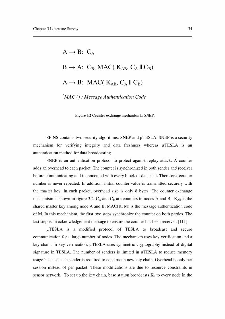
Chapter 3 Literature Survey
34
SPINS contains two security algorithms: SNEP and µTESLA. SNEP is a security
mechanism for verifying integrity and data freshness whereas µTESLA is an
authentication method for data broadcasting.
SNEP is an authentication protocol to protect against replay attack. A counter
adds an overhead to each packet. The counter is synchronized in both sender and receiver
before communicating and incremented with every block of data sent. Therefore, counter
number is never repeated. In addition, initial counter value is transmitted securely with
the master key. In each packet, overhead size is only 8 bytes. The counter exchange
mechanism is shown in figure 3.2. CA and CB are counters in nodes A and B. KAB is the
shared master key among node A and B. MAC(K, M) is the message authentication code
of M. In this mechanism, the first two steps synchronize the counter on both parties. The
last step is an acknowledgement message to ensure the counter has been received [111].
µTESLA is a modified protocol of TESLA to broadcast and secure
communication for a large number of nodes. The mechanism uses key verification and a
key chain. In key verification, µTESLA uses symmetric cryptography instead of digital
signature in TESLA. The number of senders is limited in µTESLA to reduce memory
usage because each sender is required to construct a new key chain. Overhead is only per
session instead of per packet. These modifications are due to resource constraints in
sensor network. To set up the key chain, base station broadcasts K0 to every node in the
Figure 3.2 Counter exchange mechanism in SNEP.
A → B: CA
B → A: CB, MAC( KAB, CA || CB)
A → B: MAC( KAB, CA || CB)
*MAC () : Message Authentication Code

Chapter 3 Literature Survey
35
cluster. Then, each node can generate K1, K2 … KN from K0 by using a one-way function
as shown in figure 3.3. To start secure communication, nodes use the key backward from
the last key KN to K0 so the adversary cannot generate this chain key. For example, when
an adversary can crack the message and obtain K2, it can generate K3, K4 … KN.
However, the next round of broadcasting messages will use K1 which cannot be
generated by the adversary because key chain uses one-way function, thus it only can
compute forward. However, it cannot compute backward. Therefore, stealing current key
does not affect the rest of the key chain.
µTESLA has a nonce and verification in the overhead. Nonce is a value to ensure
a freshness of data which is similar to SNEP technique. In the verification, receiving node
can verify the correct sender from the correct key. In addition, broadcasting data uses key
delay disclosure. This mechanism can avoid a problem in transmission delay and enhance
security. Since data is encrypted two keys ahead, current key can be used to verify the
packet but it cannot decrypt the data. For example, if current key uses K3, K3 is used to
encrypt a packet while K1 is used to encrypt data in the packet. When packet is received,
node decrypts the packet with K3 and waits until K1 to decrypt data. The benefit of this
mechanism is being able to decrypt with a correct key when there is packet loss or delay.
Secondly, encrypted data still cannot be revealed even though an adversary can obtain the
current key because the one-way chain cannot be computed backward. Therefore,
µTESLA supports a sensor network environment with unreliable communication and a
large number of receivers. It reduces energy consumption by using self-authenticating
keys and low overhead size in communication. However, SPINS has drawbacks in
verifying compromised nodes because there is no mechanism to determine the
compromised node. Therefore, at an initial stage if adversary could proceed as one node
in the network then the base station would provide the adversary with the key. In
addition, SPINS is based on source routing so it could expose a risk through traffic
analysis and denial-of-service attack. Furthermore, key chain is updated based on time
basis so it cannot be adaptive to the situation e.g. high risk situation and normal situation.

Chapter 3 Literature Survey
36
3.3 Intrusion Detection System
Intrusion Detection System (IDS) has been developed and improved in traditional
networks [112-117]. A decentralized IDS [118, 119] is proposed in ad hoc networks to
select IDS activated nodes. These nodes have the responsibility of monitoring a network
covering neighboring nodes and its node. An advantage of decentralized IDS is an
increase in coverage and security. Since ad hoc network spreads the nodes in large scale,
it is impractical to monitor only the base station. When an adversary reaches the base
station, it may be too late to protect ad hoc nodes. Secondly, distributing IDS through a
network minimizes the risk of attack because there are many nodes monitoring network
behavior. The adversary could easily capture a few nodes but capturing all nodes is not
simple. However, these solutions require a complicated node election process which
involves intensive communication and computation. Therefore, these solutions cannot
apply to a direct application in sensor network because of resource constraints.
The IDS in sensor network adapts traditional and ad hoc solutions to meet the
requirements. In [120], a mechanism of IDS in sensor network is proposed. The detection
model is based on rules or signature database. When behavior fails the test, an alarm is
raised. The simulation shows that straight forward attacks including message delay,
jamming, data alteration and message loss can be detected effectively. A large history
Figure 3.3 Key chain in µTESLA
K3 K2 K1 K0
Order in using key (Backward)
Order in generating key (Forward)

Chapter 3 Literature Survey
37
database also improves detection performance by nearly 100%. However, this simulation
does not consider an untrusted environment and unreliable communication. Nevertheless,
performance should be less effective than the ideal scenarios. In [121], IDS model is
improved by dynamic monitoring of sensor networks. The result shows that detection
mechanism can be configured to meet a resource in sensor network. However, a
deployment of IDS activated node is based on reliable and recognized infrastructure. The
implementation can be a challenge in practical. In [122], it supports a detection
mechanism which can be operated in sensor nodes. However, the deployment of IDS is
assumed that adversary does not know the sensor nodes location but base station and
sensor nodes recognize their locations. Nevertheless, identified location increases a cost
of extra equipments and energy, thus it may not effectively use in general application. In
addition, IDS should not rely on nodes location because adversary could identify nodes
location from physical nodes and radio detection.
From the previous section, IDS mechanism can be effectively implemented in
wireless sensor devices. However, the challenge is how to distribute the IDS in sensor
network environment to spread the energy use. As a completed solution, there are a
number of distributed IDS protocols. In [123], protocol uses a cooperative decision from
detection nodes. However, anomaly detection model and voting algorithm prove a poor
performance and high false alarm rate. To avoid these problems, distributed IDS with
localize decision are proposed [124-127]. These mechanisms improve the performance
and scalability. With a voting algorithm, high intrusion detection rate is proved in the
result [124]. However, these mechanisms are designed for wired network so it could be
difficult to directly implement in sensor network. Therefore, Agent-based IDS is
reviewed in the following section because of efficient distributed IDS and voting
algorithm in wireless network.
3.3.1 Agent-based IDS
Agent-based IDS [128, 129] which activated IDS is selected from voting as
shown in figure 3.4. Each node has one vote for their gateway. In dense clusters, the
percentage of agent nodes is reduced because each agent node can cover more
neighboring nodes. In addition, agent nodes are selected based on the number of votes,
Chapter 3 Literature Survey
38
thus the algorithm ensures that selected node is placed in high traffic. This also increases
the coverage of IDS monitoring in large cluster. However, voting requires a network
hierarchy e.g. tree structure. Hierarchy maintenance is costly in sensor networks because
network structure is changed regularly due to joining nodes, leaving nodes and node, link
failures. Hence, this voting algorithm selects agent nodes efficiently but cannot be
implemented in sensor networks directly.
3.4 Conclusion
In summary, ELK proposes efficient key management with self-generated key and
minimizes communication with hint messages. However, it requires tree structure
maintenance and regular updates between parent nodes and child nodes. Further, it is too
expensive for sensor network. SPINS introduces a key chain and reduces energy
consumption by symmetric cryptography. However, it broadcasts an actual key in setting
up and only protects this secret key by using a counter and symmetric cryptography.
Since an adversary could have high capacity computers, transmitting actual key with
Figure 3.4 Agent-based IDS where grey node activates IDS, solid line is the available network
connection and dotted line is the voted message [128].

Chapter 3 Literature Survey
39
symmetric cryptography is a weakness. In addition, at least three exchanged packets are
required to set up secure channel. It can be inefficient because sensor network is not a
reliable network so packet loss and error can occur. Since communication is the largest
energy consumer, this procedure may consume a large amount of energy. Furthermore,
key chain in SPINS is only updated on time basis. Therefore, base station cannot request
nodes to change keys corresponding to the situation unless the base station re-deploys
key chain which requires a lot of communication and energy. Therefore, the following
items are the requirements of key management in sensor network.
1. The number of messages used to establish key should be minimized because
the communication among nodes is the largest component of energy
consumption.
2. A key should be generated in its node and should not be transmitted in
communication because it can expose a security risk.
3. Base station should be able to update the key without re-deploying entire key
chain.
4. Protocol should able to manage leaving nodes, joining nodes and node failures.
Distributed Intrusion Detection System is required for increasing coverage and
security protection. Intrusion Detection System (IDS) is also important because there is
no other protection when an adversary breaks into network. Distributed IDS selects agent
nodes for activating IDS. Since a sensor network has no infrastructure and limited
resources, this is a critical challenge. Therefore, the following issues are the requirements
of distributing IDS in sensor network
1. Selecting agent nodes should select high traffic nodes in order to have higher
chance to detect more attacks.
2. Protocol use should consume a small amount of energy because sensor
network has limited resources.
3. Selected nodes should be changed each round in order to distribute energy
consumption equally in the cluster.

40
Chapter 4. Hint Key Distribution & Adaptive IDS
This chapter introduces an approach of Hint Key Distribution (HKD) and
Adaptive Intrusion Detection System (Adaptive IDS). Since chapter 3 describes the
challenges, this chapter explains protocols and mechanisms for organizing key
management and intrusion detection in sensor networks. Firstly, overview architecture
and mechanisms of HKD are described. The theoretical performance is also presented
while further evaluation is in chapter 5. This chapter continues explaining the challenges
of intrusion detection. The Adaptive IDS is proposed for organizing distributed intrusion
detection in the cluster. This chapter is concluded by discussing cooperation between
HKD and Adaptive IDS.

Chapter 4 Hint Key Distribution & Adaptive IDS
41
4.1 Hint Key Distribution (HKD)
4.1.1 Overview
Our Hint Key Distribution (HKD) is proposed for key management in sensor
networks so sensitive data can be protected. As discussed in chapter 3, sensor networks
have limited resources so key management has to be re-developed. HKD provides a
number of unique advantages. It also focuses on minimizing energy consumption and
reducing risks by transmission of the key hint. HKD is developed based on hint message
from ELK [94] and key chain in SPINS [111]. The mechanism of the protocol is
described in the next section.
4.1.2 Mechanism
To develop HKD, our objective is to secure communication and the network. We
assume that the base station has the highest computing capacity and is equipped with an
extensive power supply. Second, physical attack must be defended from attacks including
key and program stealing. In this thesis, nodes are assumed to be safe from physical
tampering. Nodes can be protected from tampering by implementing Watermarking,
Tamper-Proofing and Obfuscation [101, 130-132]. We assume that network routing is
established before performing the key distribution. The environment is assumed to be
high risk with adversaries surrounding the network. Intruders have the ability to intercept
every message of transmission as well as high performance computers and power supply
In each node, master key (KM) and common key (KC) are pre-installed. The
master key KM is an initial key for generating the key chain. It is used as an input for a
one-way function to compute a consequence key. Common key KC is used in the initial
stage in which the key has not been set up so the setting up message is encrypted and
confidential. Additionally, encryption and decryption with correct key ensures authorized
senders and receivers. In our HKD, base station generates a hint message. In addition, the
base station is the most trusted device so it takes the responsibility of broadcasting and
making decisions on key setting up and key updating.

Chapter 4 Hint Key Distribution & Adaptive IDS
42
To construct a key, there are two kinds of operations. Both sender and receiver
contain two one-way functions F1 and F2. These one-way functions can compute forward
but they cannot compute backward. Therefore, exposing current key does not affect the
key chain and master key KM. Secondly, using two one-way functions instead of one in
SPINS [111] can increase the key space, makes it more difficult for an adversary to break.
4.1.3 Implementation
Sender generates hint message which contains a hashed value of current key.
Current key KC is generated from master key KM and one-way function F1 and F2. Master
key KM is used as an input. This key generating computes both F1 and F2 iteratively as
shown in figure 4.1. As discussed in chapter 3, generating a key chain in a node can
secure the key and simplify operations. One-way function F1 is the first function to
iteratively compute for L rounds where L is a random number. Then, one-way function F2
begins to iterative compute for N rounds where N is another random number. Both one-
Figure 4.1 Procedure to find current key KC from master key KM
by using one-way function F1 and F2 where L and N are random numbers.
KM
F1
F1
F1
F2 F2 F2
KC
L t
imes
N times

Chapter 4 Hint Key Distribution & Adaptive IDS
43
way function F1 and F2 are different functions in increasing a key space which increases
the degree the difficulty of breaking the key. To compare with one one-way function, key
space increases from L to L x N. This is equivalent to increasing from O(n) to O(n2),
where L is equal to N. In addition, using two one-way functions can eliminate the need to
re-deploy master key KM because changing the key chain can be done by simply selecting
new random numbers L and N. Then, current key KC is changed to a new key chain
because changing number L shifts the key chain to a new row. In the implementation, the
random number L in the next round must be greater than the current number so key will
not be repeatedly used. In addition, more rounds of updating keys can increase key space.
For example, if random number L is in the range [1, 2, 3 … 20], after 20 rounds, the
possibility of L is in the range [20, 21, 22 … 400]. Therefore, this key chain supports a
long operation lifetime in sensor networks.
Figure 4.2 Generating hint procedure in HKD
where KC(S1|S2) encrypts S1 and S2 with common key KC.
select random number L
load key K = KM
for j = L downto 0 do
compute key K = F1[K]
end for
store key KM = K
compute hashed value S1 = H[K]
select random number N
for j = N downto 0 do
compute key K = F2[K]
end for
compute hashed value S2 = H[K]
encrypt message (S1|S2) with key KC
broadcast message KC(S1|S2)

Chapter 4 Hint Key Distribution & Adaptive IDS
44
To implement, sender is required to update master key KM from previous
computing one-way function F1 because random number L is always added on top of
previous value. Therefore, it can reduce processing time by processing from previous
data. In addition, sender needs to prepare hashed value from hash function H. The
procedure as shown in figure 4.2 begins by selecting random number L. Then, sender
performs one-way function F1 on KM iteratively L times. After that, it stores new key as a
master key KM and finds hashed value H[KM] as S1. Next, sender selects the second
random number N for number of computing one-way function F2. After completing, it
computes hashed value and stores in S2. At the same time, sender encrypts both S1 and S2
with common key KC and broadcasts to the network
Figure 4.3 Receiver procedure in HKD
decrypt message with key KC
extract S1 and S2 from broadcasted
message
load key K = KM
while H[K] not equal to S1
compute key K = F1[K]
end while
store key KM = K
while H[K] not equal to S2
compute key K = F2[K]
end while
until store K as secret key
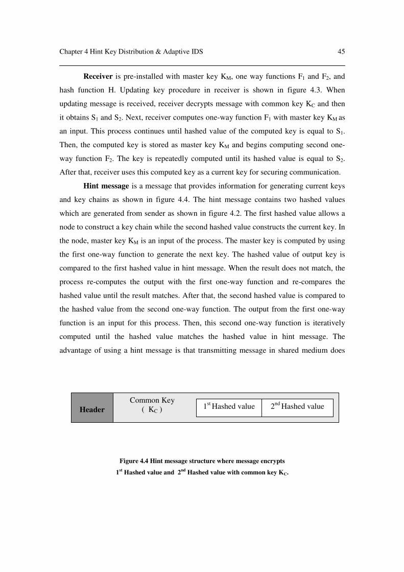
Chapter 4 Hint Key Distribution & Adaptive IDS
45
Receiver is pre-installed with master key KM, one way functions F1 and F2, and
hash function H. Updating key procedure in receiver is shown in figure 4.3. When
updating message is received, receiver decrypts message with common key KC and then
it obtains S1 and S2. Next, receiver computes one-way function F1 with master key KM as
an input. This process continues until hashed value of the computed key is equal to S1.
Then, the computed key is stored as master key KM and begins computing second one-
way function F2. The key is repeatedly computed until its hashed value is equal to S2.
After that, receiver uses this computed key as a current key for securing communication.
Hint message is a message that provides information for generating current keys
and key chains as shown in figure 4.4. The hint message contains two hashed values
which are generated from sender as shown in figure 4.2. The first hashed value allows a
node to construct a key chain while the second hashed value constructs the current key. In
the node, master key KM is an input of the process. The master key is computed by using
the first one-way function to generate the next key. The hashed value of output key is
compared to the first hashed value in hint message. When the result does not match, the
process re-computes the output with the first one-way function and re-compares the
hashed value until the result matches. After that, the second hashed value is compared to
the hashed value from the second one-way function. The output from the first one-way
function is an input for this process. Then, this second one-way function is iteratively
computed until the hashed value matches the hashed value in hint message. The
advantage of using a hint message is that transmitting message in shared medium does
Figure 4.4 Hint message structure where message encrypts
1st Hashed value and 2
nd Hashed value with common key KC.
Common Key
( KC )
1st
Hashed value 2nd
Hashed value
Header

Chapter 4 Hint Key Distribution & Adaptive IDS
46
not expose an actual key which means it is more difficult to break the key. In addition,
hashed value is smaller fixed size compared to an actual key. Therefore, energy
consumption in communication can be reduced. Finally, the process is stateless for
generating current key and key chain so they can be constructed from any hint
broadcasting. This also assists nodes with packet loss and joining nodes to generate keys.
Updating key procedure. There are two ways to perform the key update
procedure. First, updating an entire key chain is computed as shown in sender and
receiver parts. Second, updating a current key within the same key chain is quicker and
uses less energy for short term purposes. Sender uses the same master key KM and
reduces random number N to compute hashed value. Receiver is not required to compute
first one-way function F1 because it uses the same key chain. To find a current key, it
computes a shorter key chain from master key KM to second one-way function F2. In the
implementation, both sender and receiver do not to need to compute these one-way
functions F1 and F2 because this key chain has been computed previously. Therefore,
sender only looks for hashed value in previous computed key while receiver only
matches the received hashed value and the previous computed key. The structure of
memory in both sender and receiver is shown in figure 4.5. An example is assumed in
which both sender and receiver currently use master key KM and current key KC. To
Figure 4.5 Keys stored in memory.
KM
KC KC-1 KC-2 KC-3
H[KC] H[KC-1] H[KC-2] H[KC-3]
H[KM]
N times
Chapter 4 Hint Key Distribution & Adaptive IDS
47
update key, sender could randomly select KC-1. Since this key is already computed,
sender simply picks H[KM] and H[KC-1] and then encrypts with common key KC. Next, it
broadcasts to the network. When receiving this message, receiver can obtain H[KM] and
H[KC-1] by decrypting with common key KC. After that, it searches for hashing value in
memory as in figure 4.5 and obtains KC-1. An advantage of this updating key is reducing
computation which minimizes both energy consumption and delay. In addition, using a
key backward can protect against adversary computing new key from previous key
because this key chain is computed from one-way function.
Joining node and packet loss are supported by our HKD. Since next round of
key updating contains hashed value, joining nodes can generate a current key from initial
master key KM. In packet loss, next hashed value provides sufficient information for
receivers to generate a current key. In addition, the hashed value is unique so it ensures
the same current key in both senders and receivers. The only drawback is when a joining
node in a network has been in operation for some time. The joining node requires more
computation time which can cause a delay in communication.
4.1.4 Features
As HKD is implemented with hint message, key chain and key self-generating, it
provides a number of features which are described as follows.
The number of messages required in key establishment is reduced. HKD uses
key pre-distribution and hint key technique to construct a key so only one message is
required. This message contains only a hint for current key which is sufficient for
authorized nodes to construct the key. When comparing with SNEP in SPINS [111], at
least three messages are required to set up a secure channel. This can enhance system
lifetime as well as reduce setting up period.
Keys are generated in each node. In HKD, the base station gives each node a
hint so a key can be constructed from this hint. The hint message is the hashed value of
the current key. Since authorized nodes have pre-installed key, they can compute current
key from the hint. However, hint message does not provide enough information for
adversaries to generate keys because a hashed value cannot be computed backward to
find the actual key.

Chapter 4 Hint Key Distribution & Adaptive IDS
48
Updating key is flexible for base stations. In HKD, the base station can update
the key immediately to correspond to the situation by broadcasting hint message. Then,
every node will update their key from this broadcast. Therefore, their key can be updated
dynamically based on the situation. In addition, the base station can use secret key longer
in low risk environment thus energy consumption in updating key can be reduced.
In addition, hint message is very small in size so it can be attached as a part of
transmission data. If the system decides to maximize battery lifetime, base station can
attach the hint to the first block of data in each session. So receivers can update keys
immediately when the message is received. The data is also protected with the updated
key in this transmission.
Protocol supports leaving nodes, joining nodes and node failures. Since HKD
can update the key by hint message, organization of tree is not necessary. In leaving
nodes and nodes failures adjusting or communicating as in ELK [94] is not required.
Joining nodes do not require special maintenance because the hashed value in hint
message has sufficient information for new authorized nodes to generate the key.
Protocol should minimize resource consumption in key management. HKD
uses symmetric cryptography because asymmetric cryptography consumes more energy.
This also increases lifetime of the system besides compact communication. Furthermore,
HKD is stateless so it does not require a large space in memory. The memory only stores
pre-installed key, hints and current keys.
4.2 Adaptive Intrusion Detection System (Adaptive IDS)
4.2.1 Overview
As discussed in chapter 3, key management can protect networks against from
external attacks. There is no security protection when communicating among
compromised nodes. Therefore, intrusion detection system (IDS) is required to monitor
behavior in these compromised nodes. Since traditional IDS is too expensive to directly
implement in sensor networks, a new protocol is required for limited resource devices.
Chapter 3 also demonstrates that IDS mechanism can be reconfigured and implemented
in wireless sensor devices. In addition, distributed IDS also increases coverage and
enhances security in sensor networks. However, electing an activated node is a challenge

Chapter 4 Hint Key Distribution & Adaptive IDS
49
because sensor network structure could be altered frequently and the activated node
should be on a high traffic spot. These challenges are considered in the developing of our
Adaptive IDS mechanism which is described in the next section.
4.2.2 Mechanism
To develop Adaptive IDS, our objectives are electing a high traffic node and
distributing energy consumption equally in the cluster. To reduce energy consumption,
each node has an internal clock which triggers for each round of electing nodes (voting
round). Our protocol assumes that time is synchronized in every node before deployment.
Every node has pre-installed IDS software which can be activated and de-activated. In
addition, each node has a threshold number which increases quickly when IDS is
activated whereas this number slowly decreases when it does not activate IDS. A diagram
of Adaptive IDS protocol is shown in figure 4.6. When a new voting round is triggered,
every node broadcasts their voting message to neighboring nodes. Voting messages
contain node ID and current time while receivers keep all these messages from
neighboring nodes. When the voting timeout occurs, each node counts the received votes.
Then, received votes are subtracted by threshold number and kept as voting number. The
current time of received messages is sorted to find the median. If the current time of that
node differs by a large amount, time is adjusted corresponding to the median time. Then,
each node backs off for a period of time with nodes receiving higher number of votes
having a shorter backoff time. After that, a node sends a bidding message to inform
neighboring nodes that this node has a high voting number. If the receiver has a higher
voting number, it will broadcast a bidding message otherwise it will wait for the time out.
When bidding period is completed, the node with the highest voting number activates
IDS and increases its threshold. On the other nodes, IDS is de-activated and has its
threshold reduced, after which the voting procedure is finished. Since Adaptive IDS does
not use maximum power for broadcasting voting message, the cluster is separated into
many small groups each with an IDS activated node. Furthermore, threshold number can
avoid repeatedly activating IDS in the same node so energy consumption is distributed
uniformly in the cluster.

Chapter 4 Hint Key Distribution & Adaptive IDS
50
Figure 4.6 Voting procedure in Adaptive IDS for each sensor node.
Initialize the system
Broadcast a vote message
Store a vote message
Wait until time out
Calculate Voting Number from
(number of votes – threshold)
Broadcast a bidding message with
Node ID & Voting Number
Received a
bidding message
Yes
Activate IDS
& increase threshold
No
Reduce threshold
No
Completed voting
Received voting
number
<
Its Voting Number
Yes

Chapter 4 Hint Key Distribution & Adaptive IDS
51
4.2.3 Implementation
Clock adjustment. In Adaptive IDS, it is assumed that time is synchronized in
every node before deployment and inaccuracy in the clock is less than one minute each
year. The maximum operation lifetime of sensor network is five years. Therefore, the
worst case of time difference is five minutes so Adaptive IDS sets time out for ten
minutes for the waiting period. However, time in each node is adjusted based on received
message. Therefore, a node should not differ more than one minute. In addition, the
adjusted time, which is compared to median of received messages, uses a boundary of
one minute. Although there is a transmission delay, the delay in one hop broadcast is an
insignificant effect compared to one minute boundary. This procedure is shown in figure
4.7.
Figure 4.7 Clock adjusting procedure in Adaptive IDS for each sensor node.
Received voting messages
Calculate clock difference
from each message
Find the median of these
differences
Median > 1 minute
Finish clock adjusting
Adjust clock with the
median value.
No
Yes

Chapter 4 Hint Key Distribution & Adaptive IDS
52
Threshold. Adaptive IDS uses the threshold number for allocating IDS activated
nodes uniformly in the cluster. The threshold number is used to subtract a received voting
number so each node is not likely to activate IDS at all times. The threshold number has
both an increasing and decreasing delta. The increasing delta is always larger than the
decreasing delta. When node activates IDS, the increasing delta is added to the current
threshold. The decreasing delta is subtracted from the current threshold when node does
not activate IDS in that round. The initial threshold is configured as zero before the
deployment where increasing delta and decreasing delta are pre-configured. If the intent
is to deploy a dense network, increasing delta can be configured with a large number e.g.
more than five while decreasing delta is normally set at one. For example, if the
increasing delta is five and decreasing delta is one, it could avoid repeatedly activating
the same node for approximately five rounds. However, Adaptive IDS suggests that in
general the increasing delta should be set to between two to four while the decreasing
delta should use a value of one. This can change IDS activated node and select a high
traffic spot.
4.2.4 Features
Adaptive IDS is implemented with voting algorithm and threshold number.
Therefore, it provides a number of features which are described as follows.
Activated node should be placed in high traffic area. Since an activated node
must respond for both neighboring nodes and itself, it should be the node surrounded by
neighbors. Network traffic could be used for measuring density of neighboring nodes.
Adaptive IDS mechanism selects a node with the highest traffic in a region so one
activated node can cover many neighboring nodes. Voting is used to determine a number
of traffic and neighbors because a high number of votes is equivalent to a large number of
neighboring nodes. This also demonstrates a chance of intense traffic. Conversely, a low
voting number means there is less network traffic passing through that node. As a result,
the voting protocol could reduce the number of activated nodes and energy consumption
in the cluster. In addition, the high traffic nodes can monitor more events which increase
the chance of detecting an attack.

Chapter 4 Hint Key Distribution & Adaptive IDS
53
Protocol should consume a small amount of energy. Most energy consumption
in sensor networks is in wireless communication. To save in energy consumption, the
number of exchange messages in protocol should be minimized. Adaptive IDS protocol
requires transmitting one voting message for every node and one bidding message for
activated node. Therefore, Adaptive IDS protocol requires an average of two messages
for activated node and an average of one message for non-activated node. In addition, it
does not require any complicated process to elect activated node. Therefore, only a small
amount of energy consumption is required for Adaptive IDS.
Energy consumption in activating IDS should be distributed equally in the
cluster. Adaptive IDS protocol is such that activated node always monitors network and
battery could run out quicker than non-activated node. In general, Agent-based IDS
always selects the highest traffic nodes to activate IDS [128, 129]. However, a sensor
network should not repeatedly activate the same node until the battery runs out because
network will lose high traffic nodes which are the nodes with most connectivity.
Furthermore, sensor network has a large number of nodes and large coverage areas so an
objective must be to maintain the largest number of nodes in order to increase the system
lifetime. Therefore, Adaptive IDS introduces a threshold number to activate different
nodes in different rounds. The threshold number increases quickly when IDS is
repeatedly activated while it decreases slowly when IDS is not activated. As a result,
energy consumption of IDS is shared by the entire cluster.
4.3 Cooperation between HKD and Adaptive IDS
4.3.1 Overview
An intention in developing HKD is for securing network communication with
secret key while consuming only a small amount of energy in sensor networks. To
develop Adaptive IDS, our intention is to provide distributed IDS in sensor networks
where energy consumption is also uniformly distributed. Cooperation between HKD and
Adaptive IDS can reduce the individual weakness and strengthen the security because
HKD protects the network by data encryption. Adaptive IDS monitors internal network
behavior for malicious events and attacks. In addition, the mechanisms in both protocols
can support each other. The voting message in Adaptive IDS can be encrypted by using

Chapter 4 Hint Key Distribution & Adaptive IDS
54
current key from HKD in order to avoid message tampering and replay attack. In addition,
Adaptive IDS can inform the system if the current network is under attack so HKD can
update a new key chain immediately. Adaptive IDS can also detect misbehavior if
intruders attempt to corrupt an updating key in HKD. Therefore, cooperation between
HKD and Adaptive IDS can enhance the network security for both external protection
and internal detection.
4.3.2 Mechanism
Both Adaptive IDS and HKD operate in the application layer. However, they
require information to be exchanged to improve efficiency.
Adaptive IDS information. Adaptive IDS provides protection for a situation of
network and provides alerts when network is under attack. The situation may be
categorized into normal situation, suspicious situation, alert situation and extreme risk
situation. A normal situation is a situation in which IDS does not detect any violation
from the network so HKD could use current key chain longer to reduce energy
consumption. A suspicious situation is a situation in which IDS detects some rules
Figure 4.8 Exchange information procedure for Adaptive IDS.
IDS activated node
Normal
situation
Suspicious
situation
Alert
situation
Extreme risk
situation
Not inform
base station
Inform
base station

Chapter 4 Hint Key Distribution & Adaptive IDS
55
violation but still does not trigger the alert signal. HKD could shorten the period of using
the current key and change key chain regularly. Alert situation is a situation in which IDS
has found a critical rules violation so HKD immediately changes the current key and key
chain to secure the network. Finally, an extreme risk situation is a situation in which IDS
has identified a critical attack and HKD cannot update key chain e.g. due to jammed
signal. Network should apply the strongest policy e.g. apply RSA or re-start the entire
network.
HKD information. HKD provides a status of key management in the network.
The status can be classified as management status or activity status. Management status is
categorized as normal management, trust management and secure management. Normal
management uses the same key chain for a period of time while trust management uses
the same key chain for longer period because there is no suspicious event reported from
Adaptive IDS. Therefore, a system can save more energy. In secure management, key
chain is updated more often when Adaptive IDS raises an alert signal. Activity status is
categorized into idle, key updating, key chain updating and error. When there is no
activity in key management, it is called as idle. Key updating and key chain updating are
Figure 4.9 To distinguish activities of HKD in IDS activated node.
IDS activated node
No activity in
key updating
Updating
current key
Updating key
chain
Not received
update or
informed error
Idle state Key update
state
Key chain
update state
Error state

Chapter 4 Hint Key Distribution & Adaptive IDS
56
informed to Adaptive IDS when base station broadcasts the updating message. Error state
demonstrates a confliction of key management in base station or difficulty in
transmission of the updating message. This information is sent to Adaptive IDS for
improving monitoring in each situation.
4.3.3 Implementation
To exchange information, base station and IDS activated nodes are required to
cooperate. Since intrusion detection system operates in activated node which is placed
around the field, these activated nodes are required to inform HKD of the current
situation. As HKD is operated by base station, IDS activated nodes and base station need
to exchange updated information. However, increasing transmitted packets is equivalent
to increasing energy consumption in sensor nodes. Adaptive IDS does not require
transmission of updated information in a normal situation. Therefore, it only informs base
station in dangerous situations including a suspicious situation, alert situation and
extreme risk situation. A diagram which illustrates this is shown in figure 4.8.
Figure 4.10 Informing current key management from HKD to IDS activated nodes
Base station
Normal
management
Trust
management
Secure
management
Insert “00” in
key updating
message
Insert “01” in
key updating
message
Insert “10” in
key updating
message

Chapter 4 Hint Key Distribution & Adaptive IDS
57
To implement, base station is not required to inform Adaptive IDS of the current
key management activity because these nodes can classify these activities from
broadcasting message. For example, Adaptive IDS recognizes idle state when base
station does not broadcast an updating message. Key updating and key chain updating
state are recognized when base station broadcasts updating messages. In addition, error
state is recognized when Adaptive IDS does not receive the updating message for a long
period or receives the error state message from base station. A diagram of these states is
shown in figure 4.9.
For management status in HKD, base station informs the IDS activated nodes by
inserting current status in key updating message. When the IDS activated nodes receive
the key updating message, they also recognize the current management status. For
example, key updating message has 2 bits for current management status where normal
management is represented with “00”, trust management is represented with “01” and
secure management is represented with “10”. A diagram which illustrates these tasks is
shown in figure 4.10.
4.4 Conclusion
In summary, this chapter demonstrates our proposed solution for security in
sensor networks. There are two main components in the system: Hint Key Distribution
(HKD) and Adaptive Intrusion Detection System (Adaptive IDS).
Hint Key Distribution (HKD) manages key distribution in the network by using
the base station. The base station generates and broadcasts hint messages to the network.
The hint message contains hashed value of current key chain and current key so
authorized nodes can construct keys corresponding to this information. Keys are
constructed from iterative computation of two one-way functions. In addition, hint
message supports joining nodes and packet loss because key construction is stateless. An
important benefit in HKD is the minimizing of energy consumption in communication
while the base station can dynamically update key based on the situation.
Adaptive Intrusion Detection System (Adaptive IDS) is a process for selecting an
IDS activated node in the network. As distributed IDS enhances coverage and security,
some sensor nodes should activate IDS. Adaptive IDS uses voting algorithm with a

Chapter 4 Hint Key Distribution & Adaptive IDS
58
threshold to select a high traffic node to activate while avoiding repeatedly activating the
same node. Since monitoring the network is an energy intensive activity, repeatedly
activating the same node could exhaust the battery quicker than the other nodes. Ideally,
all nodes should have an equal lifetime. Therefore, our threshold method in Adaptive IDS
ensures that uniform energy consumption in IDS is maintained in the sensor network. In
addition, Adaptive IDS protocol consumes a small amount of energy in voting procedure
where messages transmitted is on average two messages in activated nodes and one
message in non-activated nodes.
As a cooperative system, both HKD and Adaptive IDS can improve efficiency by
sharing information. HKD provides a management status and set of possible current
activities. Management status is categorized into normal management, trust management
and secure management. Current activity is categorized into idle, key updating, key chain
updating and error state. In Adaptive IDS, there are four situations including normal
situation, suspicious situation, alert situation and extreme risk situation. The IDS
activated node is required to inform base station in suspicious, alert and extreme risk
situations. In normal situation, IDS does not detect any rules violation so HKD can use a
current key for a longer period to save energy. In suspicious situation, IDS detects a
minor rules violation so HKD updates current keys regularly. In an alert situation, IDS
detects critical violation and triggers the alarm so HKD updates key chain immediately.
In extreme risk situation, IDS raises an alarm and HKD cannot update the key
immediately so base station applies the strongest policy e.g. restart the entire network.
To implement both protocols, network is protected from external attack by key
management HKD while internal attack is monitored by Adaptive IDS. Also, energy
consumption in the protocols is kept to a minimum to ensure that both protocols are
usable in sensor networks. Furthermore, the cooperation between the two protocols
improves dynamic operation so energy consumption is reduced in a safe environment
while security is strengthened in a dangerous situation.

59
Chapter 5. Evaluation
This chapter gives an evaluation of HKD, compared with ELK and SPINS in key
management. In the second section, Adaptive IDS is compared with Agent-based IDS
[128, 129], core and boundary defense. The chapter begins by description of metrics,
parameters and scenarios in the evaluation. Models are then constructed. Finally,
cooperation between HKD and Adaptive IDS is analyzed and compared with the non-
cooperative protocol.

Chapter 5 Evaluation
60
5.1 Hint Key Distribution (HKD) Evaluation
This section describes metrics for evaluating key management including HKD,
ELK and SPINS. Then, we define the operational scenarios in the evaluation. Finally, the
performance of HKD, ELK and SPINS are analyzed and discussed.
5.1.1 Metrics of Performance
5.1.1.1 Security Strength
This metric is required to determine the strength of security from attacks
including brute force attack, known plaintext attack, replay attack, man-in-the middle
attack and denial of service attack. Since a main objective of key management is to
prevent intruders, the attacks on protocols must be evaluated.
5.1.1.2 Resource Usage
The metric considers the amount of energy consumption in communication and
computation. As communication is the most energy intensive activities in sensor
networks, it must be minimized. This metric also determines the system lifetime for the
protocol operations.
Sensor network devices have a limited resource so protocol must use this resource
efficiently. Processing time and memory are also considered because these are limited in
sensor networks.
5.1.2 Parameters of Evaluation
Parameters of the key management evaluation are explained. These parameters
are considered in security and resource usage.
5.1.2.1 Security Strength
Simulated attacks are used for evaluating key management because they
demonstrate the resistance of protocols against a cryptographic analysis which adversary
uses for breaking the key. Key space is a parameter that is used in comparison of the
security strength because a larger key space means a longer time to break the key. In

Chapter 5 Evaluation
61
addition, each attack exploits different vulnerabilities. Brute force attacks can be used as
a benchmark to estimate an average time to find the current key. Known plaintext attack
is evaluated with the situation that part of the information is exposed so the time to find
the current key is expected to be reduced. Replay attack is evaluated whether or not the
protocol is vulnerable to message replay. Similarly, vulnerabilities of the man-in-the-
middle attack are evaluated.
5.1.2.2 Resource Usage
The number of messages, message size and frequency are used as parameters
because communication is the most energy consumption in sensor networks. The
evaluation uses this information to calculate an estimation of system lifetime.
Processing time is used to determine the computing capability of Central
Processing Unit (CPU). Memory size is also needed to determine the requirements in
implementing protocols because sensor network devices have limited memory size.
5.1.3 Evaluation Scenario
To standardize the evaluation, SmartDust [102, 133-137], Strong Arm chips [102,
138] and Xscale [102, 139-142] are used as analysis platforms. Power is supplied from 3
volts battery with capacity of 2,200 mAh. Our model sets up 10 nodes in each cluster and
sampling rate is 1 Hz with 50 Kbps bandwidth. Wireless communication consumes 4.8
mA in receiving and 12 mA in transmitting. In idle mode, energy consumption rate is 5
µA. In addition, there is end-to-end data communication between node A which is a base
station of the cluster and node B which is placed in the cluster. A path between A and B
is connected along the nodes in the same cluster as: A → n1 → n2 → …nm → B. This
network also has a routing path set up. Each node in network has a strong physical
protection. Adversaries cannot break the device to retrieve the key or data inside directly.
Also, the length of secret key is evaluated with 40 and 128 bits. To compute the key
chain, MD5 and SHA-1 are used as hint functions (H) to evaluate the protocols.

Chapter 5 Evaluation
62
Adversaries have Sun UltraSparc II 440 MHz server. The UltraSparc is 64 bits
RISC based on architecture with 16 KB data cache and 2 MB external cache. Its wireless
antenna can reach the entire network. When an adversary launches attacks, it can be
initiated from anywhere along a path.
The Prowler software [143] is a simulator used for the security strength and
energy consumption. Prowler is a wireless network simulator which is based on
MATLAB. The simulator is based on an event-driven model and supports graphic
interface as shown in figure 5.1. The operation of nodes is developed on an event basis as
shown in figure 5.2. For periodic tasks, clock parameter or Clock_Tick could be used for
Figure 5.1 GUI of Prowler software [143].

Chapter 5 Evaluation
63
assigning the task. A wireless communication is built in the program which can adjust the
parameters e.g. signal strength and error rate. Our adversary in simulator is also
developed in this Prowler with high processing capability (UltraSparc II) and high
transmitting power. Sensor network nodes are equipped with limited capacity battery and
less transmitting power than adversary. The energy consumption varies with signal
power, message size and activities. Simulation results are exported to MATLAB for
further analysis.
Figure 5.2 Example of source code in Prowler [143].
switch event
case 'Init_Application'
signal_strength=100;
%%%%%%%% Memory initialized here %%%%%%%%%%%%
memory=struct('send',1, 'signal_strength',
signal_strength);
%%%%%%%%%%%%%%%%%%%%%%%%%%%%%%%%%%%%%%%%%%%%%%%%%%%%%%%
if ID==1 % first node starts flood
Set_Clock(1000)
end
case 'Packet_Sent'
% do nothing
case 'Packet_Received'
if memory.send
p=sim_params('get_app', 'P');
if rand<p
Send_Packet(radiostream(data,
memory.signal_strength));
end
memory.send=0;
end
case 'Collided_Packet_Received'
% this is for debug purposes only
case 'Clock_Tick'
Send_Packet(RadioStream(data,
memory.signal_strength));
end

Chapter 5 Evaluation
64
5.1.4 Performance Model
This section presents the theoretical model of ELK, SPINS and HKD security
strength and resource usage metrics.
5.1.4.1 Performance of ELK
Security Strength. For the number of key bits n, key space is 2n. The adversary is
required to compute at least 2n-1 keys in brute force attack [94]. To update key, hint
message is used to hide an actual key from the adversary. In addition, the adversary has
some difficulties in obtaining the group key because a cluster contains a large number of
nodes. This is a significant advantage in sensor networks because network size tends to
be hundreds or thousands nodes.
Resource Usage. Energy is used to compute and broadcast messages in the
established tree when nodes join or leave the network. When nodes are joining, each node
can compute individually without broadcasting messages. To update the key, a hint
message is broadcast in order to allow new key to be constructed. The best scenario for
effective energy consumption is that each node updates its key without broadcasting
messages. This only requires small computation and memory. In the average case, hint
messages are broadcasted so each node needs to consume power in communication and
computing new key. The hint message size corresponds to the number of left and right
contribution nodes in the tree because hint messages are generated from all keys in child
nodes. In the process of key construction, firstly a message is decrypted, and secondly to
match with the hint, the key is computed. The worst case scenarios are both setting up
tree and leaving nodes. The server begins computing a new key, which corresponds to the
current existing nodes, and broadcasts the updating message. Each node, then, computes
its key. Therefore, it requires the number of messages to verify the status of tree and
broadcast updating messages as well as computing key in each node.
As tree structure needs to be maintained, a regular communication is required for
ELK. In addition, this protocol does not support packet loss because the consecutive
packet loss can be interpreted as leaving node, and consequently tree needs to be re-
constructed. Furthermore, changing key in the child nodes requires the entire parent

Chapter 5 Evaluation
65
nodes to be updated, which is quite expensive. For concrete evaluation, the result is
shown in next section.
5.1.4.2 Performance of SPINS
Security Strength. Key space is 2n
where n is key bits, so brute force can find the
current key on average by computing 2n-1
times. Yet, decrypting message requires two
keys so brute force needs to compute at least 2n keys. To find a key chain, key space is
N·2n where N is the maximum number of possible keys in the key chain. However,
adversaries have a difficulty in obtaining number N because it has never been stated in
any message. Therefore, adversaries require computing all possibilities by beginning
from small number of N. For example, N·2n where N begins from 1, 2 … ∞. Hence, the
maximum computing time of a master key is N!·2n. When a base station updates a new
key chain, an adversary is required to re-compute this key chain again. Therefore, a key
chain is protected by security that is higher than that for a simple key. In addition, a key
chain is regularly updated, thus the key chain is secured in a period of time.
Resource Usage. With SmartDust node, 98% of energy consumption is from
communication which can be categorized into data transmission with 71%, header
transmission with 20% and Nonce transmission with 7%. Computation uses only 2% of
energy cost as shown in table 5.1. Although most energy consumption is from
communication, it is a common behavior in sensor networks. In computing, processing
time in key set up is 3.92 ms [111]. Memory uses 120 bytes for the protocol. Therefore,
SPINS demonstrates a capability of implanting security in sensor nodes.
71% Data transmission
20% Header transmission
7% Nonce transmission (Freshness verification)
2% Encryption computation
Table 5.1 Energy cost in SPINS [111].

Chapter 5 Evaluation
66
5.1.4.3 Performance of HKD
Security Strength. Key space is 2n
for current key where n is key bits so an
average 2n-1
computation is required for brute force attack. To compute the current key
chain, the key space is N·2n where N is the maximum number of possible keys in each
key chain. To find a master key in HKD, key space is L·N·2n where L is a number of
possible key chains. However, adversaries have difficulties in obtaining numbers L and N
except the node that has already obtained all master keys, key chains and current keys
because there is no information stated on the numbers. Since the number of L and N
could be varied from zero to infinity, it is infeasible to calculate the maximum number of
L and N in one time. The adversary requires computing from smaller numbers of L and N.
Ideally, the adversary begins computing each set as follows.
(L=1, N=1), (L=1, N=2) … (L=1, N=N);
(L=2, N=1), (L=2, N=2) … (L=2, N=N);
…
(L=N, N=1), (L=2, N=2) … (L=L, N=N).
Although the adversary could keep the previous computing numbers L and N, it is
infeasible to store the previous 2n x L x N in UltraSparc II. Therefore, the adversary
needs to re-compute numbers L and N. As a result, the maximum computing time of key
chain is N!·2n while the maximum computing time of master key is L!·N!·2n. Therefore,
master key is the largest key space in HKD which is equivalent to the most secure key.
Resource Usage. As HKD uses the similar one-way function as SPINS, memory
usage is equal to 120 bytes. However, key set up requires the comparison of hint so it
requires more 80 bytes. In addition, key chain needs to be stored in memory all the times.
If key size is 64 bits, 80 bytes of memory is required for key chain size of 10. Therefore,
the total memory is approximately 280 bytes. In simulation, 400 bytes memory is
reserved, but on average it uses 200-350 bytes. In communication, energy use is less than
SPINS because the number of communication is reduced and message size is smaller.
The details are demonstrated in next section.

Chapter 5 Evaluation
67
5.1.5 Evaluation
5.1.5.1 Security Strength
ELK, SPINS and HKD are evaluated from brute force attack plain attack, replay
attack, man-in-the middle attack and denial of service attack.
Brute Force Attack is computed by adversaries and described in section 5.1.3.
In general, a larger key space increases the time of finding the correct key. As shown in
figure 5.3, increasing key bits increases a computation time. In these three protocols, the
strength of the current key is based on the number of key bits. The larger key bits show a
stronger security is similar as an ideal model. For example, to compare between 128 bits
key and 64 bits key, it is necessary to make brute force compute the average 2127
and 263
times respectively. Therefore, usage time in computation increases by 1.84x10¹⁹
times. In
SPINS, a decrypting message must use two keys: current key and second next key.
Therefore, brute force must use two times more than the others or 2n. As UltraSparc II
computes each key in 2 µs [144], it requires 1.10x10⁶ seconds (~12.7 days) for 40 bits
key. To compare with 128 bits key, it requires 3.4x1032
seconds (~ 1.08x1025
years).
1
1000
1E+06
1E+09
1E+12
1E+15
1E+18
1E+21
1E+24
1E+27
1E+30
1E+33
Lo
gari
thm
of
Co
mp
uta
tio
n t
ime (
s)
32 40 48 56 128
Key length (bits)
Figure 5.3 Logarithm of computation times for current key in brute force attack.

Chapter 5 Evaluation
68
Therefore, the protection of a current key from these three protocols is sufficient for a
general use because a key is often changed. However, sensitive data should use a larger
key such as 128 bits.
SPINS and HKD use a key chain to generate a current key whereas ELK does not
have a key chain. A key chain is expected to be more secure than a current key because it
can generate all the keys for a period. As shown in figure 5.4, a larger key chain increases
computing time in an adversary. In practice, the number of keys in each key chain is
unknown so adversary needs to compute all key chain sizes. For example, if the
maximum key chain size is 10 in UltraSparc II, brute force will find 40 bit key chain in
3.99x10¹²
s (1.27x10⁵ years) and 128 bits key chain in 1.23x10
39 s (3.91x10
31 years).
A master key in HKD is protected with more key space which the size is L!·N!·2n
as explained in section 5.1.4.3. Since number L is added in the previous round, the total
value of number L increases each round. Therefore, key space increases every key
updating. For example, if L is in the range [1, 2, 3 ..., 10], then the maximum number of
L is 10. Key space for master key is 10!·N!·2n in the first round. However, after 10 rounds
11E+181E+361E+541E+721E+90
1E+1081E+1261E+1441E+1621E+1801E+198
Lo
gari
thm
of
Co
mp
uta
tio
n t
ime
s (
s)
32 40 48 56 128
10 keys
20 Keys
50 Keys100 keys
Key length (bits)
10 keys
20 Keys
50 Keys
100 keys
Chain length
Figure 5.4 Logarithm of computation times for the key chain in brute force attack.
Chapter 5 Evaluation
69
key space increases to 100!·N!·2n which is 2.57 x 10
151 times larger. Therefore, a master
key is protected more secure than a key chain and a current key in HKD.
In brute force attacks, although the current key in ELK, SPINS and HKD has the
same key space size, SPINS has the advantage in using two keys for the decryption of
messages. ELK lacks regular updating in individual current key because a group key is
based on other node keys. To update a key in one child node, all parent nodes also need
to update their keys. However, ELK has an advantage in the group key because a larger
number of nodes increase difficulty for the adversary to break the group key. For the key
chain in both SPINS and HKD, key space has the same size so it has the same security
strength. In addition, HKD master key is the most secure key, especially when key chain
is updating many times.
In a long term, the current key is periodically updated in these three protocols so
the adversary must obtain the current key in a short period of time. Since the key chain in
SPINS and HKD is used backward, it ensures that the adversary could not generate the
next key. In ELK, next key depends on the other nodes. If the adversary does not obtain
the other node’s key, it cannot generate the next key. A master key in HKD is not
renewed regularly so it has more risk than SPINS. Although HKD does not expose
information of master key, if the adversary can obtain related information, it is a risk for
HKD.
Known Plaintext Attack is an attack where an adversary obtains a part of
information to assist in revealing the key. Since this information is a clue for the key, the
key space is reduced corresponding to the information. Group key in ELK and the current
key in both SPINS and HKD are vulnerable to this attack to the same extent. In our
simulation, when the adversary has retrieved sufficient information to cut the key space
down to 50%, it reduces computation times by more than 99%, compared to a brute force
attack. According to our case study, in brute force attack, 40 bits key is originally
revealed in 1.10x10⁶ s (12.7 days), reduced to 104.5 s (1.7 minutes). Therefore, the
current key with small bit number is crucial with this attack. Although key chains in ELK
and HKD are still difficult to break, they can be critical when combined with other
attacks. In the case of master key in HKD, a hint message does not expose any
information or is related knowledge so it is not vulnerable to this attack.

Chapter 5 Evaluation
70
Replay Attack is an attack in which transmission messages are repeated or
delayed. In SPINS and HKD, a current key is updated regularly compared to updating on
event basis in ELK. Therefore, these two protocols ensure the freshness of the key to
avoid the adversary using replay message. In addition, SPINS has a benefit in using a
nonce which is a counter for protecting network from replay attack. As a result, SPINS is
the only protocol in these three protocols that has a nonce in the communication,
therefore it is the most secured against replay attack.
Man-in-the-middle Attack is an attack that focuses on the weakness of sender
and receiver validation. In ELK, SPINS and HKD, security only relies on a current key. It
is sufficient to protect real time and general data, but not sensitive data. When a current
key is revealed, the attack could do major harm to the network including substitution and
phishing attack. So, the sensitive data requires encrypting with another password.
Denial of Service Attack (DoS) is one of the most severe attacks in sensor
networks since it could jam network and burn out the batteries. It can also operate in the
physical layer which these protocols cannot control. Our simulation shows that DoS can
empty the battery in sensor nodes by continuously transmitting messages for 1.24 days.
In the case that the adversary can encourage sensor nodes to reply the messages, it could
empty the battery in 9.69 hours in the worst case scenario. The consequence from high
power signal is that network could be jammed and blocked from surrounding nodes.
In summary, security of the current key in ELK, SPINS and HKD is roughly
equivalent in general use. However, SPINS has better security protection by using two
SPINS HKD ELK
Regular renew key √ √
Regular renew key based on event √
Regular renew key chain √ √
Regular exchange information among nodes √ √
Regular verify time counter (Nonce) √
Table 5.2 Security features in each protocol.

Chapter 5 Evaluation
71
keys in decrypting message although key space does not significantly increase. Key chain
in both SPINS and HKD is secured with a larger key space ensured a longer computing
time for attackers. In addition, a master key in HKD has the largest key space among all
the keys which are equivalent to the most secure key. However, HKD does not renew the
master key regularly so it could be revealed in a long term. Furthermore, all three
protocols only rely on the key, so the adversary could do harm to the network if a key is
revealed. Finally, all three protocols are not able to resist a denial of service attack.
5.1.5.2 Resource Usage
This section evaluates ELK, SPINS and HKD in resource usage and energy
consumption. As wireless communication is the most energy consumption in sensor
networks, our simulation focuses on the message transmission
Table 5.3 is the simulation result which shows the energy consumption in HKD,
SPINS and ELK. This simulation focuses on the message size and system lifetime. The
estimated system lifetime is calculated from protocol operations which neglect sensors
and non-related operations. ELK (best case) updates the key by self-generating with the
low number of messages. In ELK (average), hint messages and tree maintenance
messages are used. ELK (worst case) needs to re-organize tree structures frequently due
to packet loss and leaving nodes. Therefore, exchanging messages and many key updates
Protocol Message size
(bytes)
Estimated operation time
(days)
ELK (best case) 23-38 967
ELK (average) 23-38 108
ELK (worst case) 23-38 53
SPINS 598 277
HKD 64 715
Table 5.3 Energy consumption in communication for each protocol.

Chapter 5 Evaluation
72
are required. In SPINS and HKD, the protocols do not reflect the structure of network so
simulation uses the average scenarios.
The result shows that the expected lifetime in HKD is almost three times greater
than SPINS because SPINS requires an authentication among the nodes before
transmitting the data. In addition, ELK (average) and ELK (worst case) consumes more
energy than HKD because ELK uses a tree to distribute keys, which are opposed to
traditional broadcasting in HKD. Additionally, a leaving node in lower branch of the tree
in ELK requires many messages to adjust the tree as well as update the key. Although
ELK (best case) shows the best performance, it rarely occurs in practice because sensor
networks are unreliable and many unexpected events often occur. SPINS demonstrates
the average performance among three protocols because it reduces the number of
communication and uses a self-generating key. HKD shows the best energy consumption
because it uses only one broadcasting message to set up the key while joining nodes do
not need the extra communication. In addition, packet loss does not affect the key
generating in HKD.
In computing resource, our simulation uses MD5 as a hash function. MD5
consumes 0.59 µJ/byte, which can be compared to 3DES computation 6.04 µJ/Byte [144].
So sensor nodes have the capability to compute this function and are also able to perform
HKD. High power processor Strong Arm chip computes each MD5 140 µs in small
wireless network device [144]. In simulation, random numbers L and N are in the range
of 1, 2, 3 … 20. On average, MD5 is required to be computed 20 times (average 10 times
each for L and N). This equals to 2.80 ms (140 µs x 20 times). To compute MD5 in low
power CPU (Xscale in energy safe mode), it requires 180 µs [144] for each computation
or 3.60 ms (180 µs x 20 times) per key distribution. HKD uses the similar one-way
function as in SPINS. Therefore, the total operation time is the sum of hash function and
one way function. As each one way function uses 3.92 ms, two one way functions use
average 7.84 ms. The total time in generating key in HKD is between 10.64 ms and
11.40 ms. Therefore, our simulation ensures that computation time in HKD does not
exceed the capabilities of a sensor node. However, this processing time is more than 3.92
ms in SPINS. In ELK, it is the worst performance in simulation because operations in the
protocol are involved with asymmetric cryptography. It uses up to 2 minutes for

Chapter 5 Evaluation
73
generating key in the deep tree hierarchy. In summary, the highest computation time is
for ELK which is a large difference from HKD and SPINS because ELK does not focus
on energy consumption and using asymmetric cryptography. SPINS uses the average
energy consumption while HKD saves most energy because of the least communication
messages.
ELK uses the largest size memory because of asymmetric cryptography. In the 10
levels tree, 6.86 MB is used to compute a key which is infeasible for sensor nodes.
SPINS uses only 120 bytes memory for the protocol. In addition, HKD uses 280 bytes in
the memory. Therefore, both SPINS and HKD could be implemented in sensor nodes
while SPINS is the most efficient in memory usage.
In conclusion, approximately 98% of energy usage in the protocols is from
communication task as shown in table 5.1. The larger bits keys provide a significant
improvement in security networks as shown in figure 5.1 and 5.2. The characteristic of
the protocols are shown in table 5.2 and 5.4. Finally, the comparisons of energy
consumption in these protocols are shown in table 5.3. ELK uses an excessive resource
especially memory and CPU which are infeasible to implement in sensor networks. The
reason is that ELK uses asymmetric cryptography and it does not focus on minimizing
the resource usage. In SPINS, memory and CPU usages are the lowest among three
protocols followed by HKD and ELK respectively. In addition, HKD uses the lowest
energy in operation. Therefore, HKD can enhance the most system lifetime. However, it
still uses memory and CPU processing more than SPINS.
HKD SPINS ELK
Not require re-organizing structure √ √
Self-generating key √ √
Support packet loss √ √
Construct key from hint message √ √
Not require exchanging information √
Table 5.4 Energy saving feature in each protocol.

Chapter 5 Evaluation
74
5.2 Adaptive Intrusion Detection System Evaluation
This section describes metrics that are used to compare Adaptive IDS to Agent-
based IDS [128, 129], core defense and boundary defense. We also define the operational
scenarios to be used for evaluation. Finally, a comparison of Adaptive IDS and the others
is analyzed and discussed.
Adaptive IDS is described in section 4.2. The protocol selects high traffic nodes
to activate IDS. These nodes monitor the network for suspicious events and raise alarm
when needed. The voting algorithm ensures that selected nodes are in the traffic areas so
the number of activated nodes can be reduced. In addition, threshold number in the
algorithm expects to reduce the repeated activating in the same nodes.
5.2.1 Metrics of Performance
5.2.1.1 Efficiency in Distribution
The metric analyzes coverage area to determine the effectiveness of IDS
distribution. The main objective in distributing IDS activated node is to increase coverage,
so the coverage area needs to be evaluated. In addition, the distribution should be
evaluated on the basis of the efficiency of spreading IDS activated node. In ideal model,
distribution should select nodes uniformly.
5.2.1.2 Energy Consumption
Energy consumption in distributing IDS is the most important constraint for
sensor networks. Since sensor networks require a long period operation, the energy
consumption in distribution must be at a minimum level. The energy usage in distributed
IDS involves communication and IDS activation. Therefore, the number of messages and
activated nodes should be at a minimum.
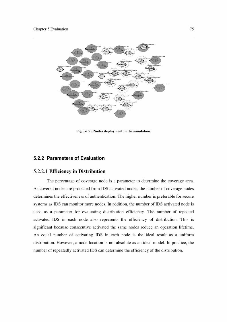
Chapter 5 Evaluation
75
5.2.2 Parameters of Evaluation
5.2.2.1 Efficiency in Distribution
The percentage of coverage node is a parameter to determine the coverage area.
As covered nodes are protected from IDS activated nodes, the number of coverage nodes
determines the effectiveness of authentication. The higher number is preferable for secure
systems as IDS can monitor more nodes. In addition, the number of IDS activated node is
used as a parameter for evaluating distribution efficiency. The number of repeated
activated IDS in each node also represents the efficiency of distribution. This is
significant because consecutive activated the same nodes reduce an operation lifetime.
An equal number of activating IDS in each node is the ideal result as a uniform
distribution. However, a node location is not absolute as an ideal model. In practice, the
number of repeatedly activated IDS can determine the efficiency of the distribution.
Figure 5.5 Nodes deployment in the simulation.

Chapter 5 Evaluation
76
5.2.2.2 Energy Consumption
Parameters in energy consumption are the number of IDS activated nodes and
transmitting messages. Firstly, the number of IDS activated nodes can determine the
energy usage in the entire cluster so less activated nodes are equivalent to less energy
usages. Secondly, the number of activated nodes should be kept at a minimum to enhance
the system lifetime. Since communication in sensor networks consumes most energy,
transmitting messages determine the energy consumption in the distribution process. As
voting procedure involves in exchanging messages, reducing transmitting message also
reduces energy consumption.
5.2.3 Evaluation Scenario
In evaluation, network topology is developed with a base station located at the
centre of a cluster. The cluster sizes are 10, 20, 40 and 80 nodes. The protocols are
developed in Prowler software [146, 147] and Ptolemy II software [148-151] based on
TinyOS structure. In this package, it contains sensor networks operations and
communication components. Therefore, we create Adaptive IDS operated on application
layers. The IDS mechanism detects an unusual behavior from rules violating. After the
Figure 5.6 An example source code of sine wave [145].

Chapter 5 Evaluation
77
IDS detects vulnerability, it raises an alarm signal to prepare for intruders. The scenarios
with the same cluster size use the same deployment for result consistency. The
deployment is shown in figure 5.5.
In simulation, only activated nodes operate traffic monitoring. Attack messages
are imitated with communication messages with slightly modified contents and formats.
Therefore, the adversary transmits alike actual communication message. The numbers of
attacks are based on simulation models and cluster sizes.
The simulation in Ptolemy software is constructed as a module object. A source
code is based on XML and JAVA as shown in figure 5.6. The software allows developers
to create an operation flow in GUI as shown in figure 5.7. Wireless components are built
in the software which can adjust the transmitting range. To develop sensor nodes, we add
components in the node and connect the flows of these components. The components in
this simulator include clock, operation, computation, calculation and wireless connection.
Figure 5.7 GUI of Ptolemy software [145].

Chapter 5 Evaluation
78
The modules in Ptolemy are constructed hierarchically. The top level is an actor which a
developer could insert operation, ports and link. After creating the actor, developers
could create the data flow from input ports through operations module and output to
external port. This includes a document link and defined parameters as shown in figure
5.8. In addition, we develop our Adaptive IDS module to cooperate with other
components. Finally, simulation results are exported for further analysis.
Figure 5.8 Hierarchical abstraction in Ptolemy [145].

Chapter 5 Evaluation
79
5.2.4 Performance Model
5.2.4.1 Performance of Adaptive IDS
Adaptive IDS selects IDS activated nodes by an adaptive voting algorithm. This
algorithm uses threshold number to reduce repeatedly activating the same node. As
Adaptive IDS uses one hop count in voting, the coverage area is expected to be 100%.
For example, if one hop neighboring node does not activate IDS, it must activate IDS
itself. However, sensor nodes are rarely used as a stand alone device, so it normally
selects some activated nodes. To distribute activated nodes, Adaptive IDS spreads the
activated nodes in the entire network. However, the location of nodes affects the
distribution because voting is based on one hop range.
In energy consumption, Adaptive IDS transmits the average two messages for
activated nodes and average one message for non-activated nodes. In the ideal model, the
number of activated nodes is based on the number of sub group. Since each sub group has
one activated node, the number of sub group determines the number of activated nodes.
Therefore, the number of activated is expected to be as O(log(n)) in theory.
5.2.4.2 Performance of Distribution Agent
Agent-based IDS [128, 129] selects IDS activated nodes by the voting algorithm.
The voting selects the highest voted nodes (or gateway nodes) to activate their IDS. In
one hop voting, the coverage area is expected to be 100% because voting message
reaches nodes in one hop range. However, a greater hop count reduces the coverage area.
A distribution for Agent-based IDS does not spread the activated node unless the network
topology changes because the gateway is expected to be an activated node. Therefore,
there is no dynamical distribution in Agent-based IDS.
In energy consumption, transmitting message is expected to be one message per
node in each round because each node only sends one message to the gateway. However,
energy is consumed more for the maintenance of the tree structure. In addition, the
number of activated nodes is corresponded to the number of hop count. In one hop count,
every parent node is expected to activate IDS therefore the number of activated node is
expected be O(n).

Chapter 5 Evaluation
80
5.2.4.3 Performance of Core Defense
Core defense is a traditional static defense strategy which selects activated nodes
surrounding base station. It ensures that no intruder breaks into a base station in each
cluster. This model defends from the most inner point and strikes back to the outer area.
As core defense is the static strategy, the same nodes repeatedly activate IDS. The
coverage area is very limited in core defense because its intention is to protect base
station. The coverage area varies with cluster size and node density. In the ideal model,
monitoring range surrounds the base station so the coverage area can be evaluated as a
circle which is shown in figure 5.9.
Therefore, the ratio of coverage area is
2
2
R
r
where r is radius of monitor range and R is radius of cluster.
This can be simplified as
2
R
r
Figure 5.9 Core defense model.
R
r
Base station
IDS activated
node
Non IDS
activated node
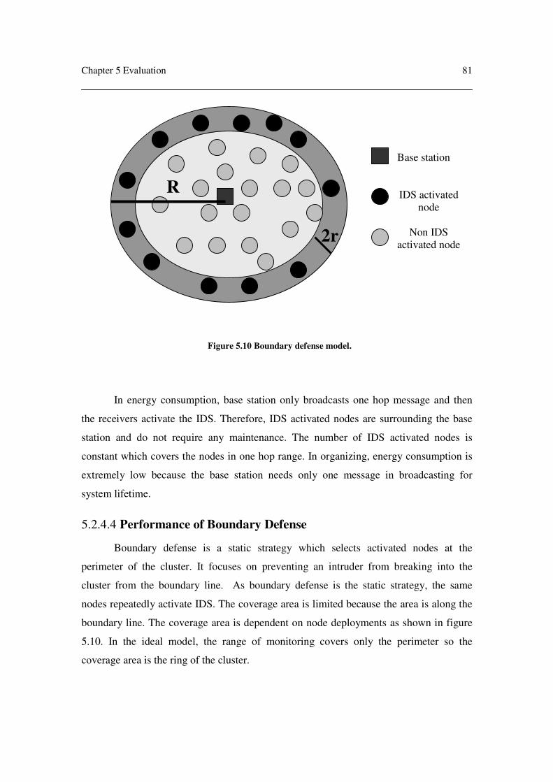
Chapter 5 Evaluation
81
In energy consumption, base station only broadcasts one hop message and then
the receivers activate the IDS. Therefore, IDS activated nodes are surrounding the base
station and do not require any maintenance. The number of IDS activated nodes is
constant which covers the nodes in one hop range. In organizing, energy consumption is
extremely low because the base station needs only one message in broadcasting for
system lifetime.
5.2.4.4 Performance of Boundary Defense
Boundary defense is a static strategy which selects activated nodes at the
perimeter of the cluster. It focuses on preventing an intruder from breaking into the
cluster from the boundary line. As boundary defense is the static strategy, the same
nodes repeatedly activate IDS. The coverage area is limited because the area is along the
boundary line. The coverage area is dependent on node deployments as shown in figure
5.10. In the ideal model, the range of monitoring covers only the perimeter so the
coverage area is the ring of the cluster.
Figure 5.10 Boundary defense model.
Base station
IDS activated
node
Non IDS
activated node
R
2r

Chapter 5 Evaluation
82
Therefore, the ratio of coverage area is ( )
−2
22
2 ¶- 
R
rRR
where r is radius of monitor range of each node and R is radius of cluster.
This can be simplified as
−R
rRr4
In energy consumption, the base station is required to transmit prune messages so
the last node in each prune is the boundary node. Then boundary nodes are activated IDS
in their nodes. Theoretically, this procedure would be performed only one time in the
system life time. Therefore, constructing a strategy uses only small amount of energy. In
addition, the number of activated nodes is a constant and varied on the node deployment.
5.2.5 Evaluation
5.2.5.1 Efficiency in Distribution
As discussed in section 5.2.4, the coverage area of Adaptive IDS is expected to be
100% similar as one hop voting in Agent-based IDS. However, the core defense and the
boundary defense have smaller coverage area. To verify, we set up a simulation with
cluster sizes 10, 20, 40 and 80 and attacks from adversaries. The attacks are launched
from adversaries that are categorized into three types. A core attack launches attack
messages in the area that is close to the base station while the boundary attack launches
attack messages at the perimeter line. Inner attacks launch an attack message to the area
between core and boundary. Since we focus on the efficiency of distribution, we neglect
the number of false negatives. If IDS in activated node detects more than 50% of attacks,
we define this to be detectable whereas define less than 50% of detect rate to be non-
detectable. As shown in table 5.5, the result supports that Adaptive IDS and Agent-based
IDS are detectable ranging from small to large size of clusters because voting algorithm
in Adaptive IDS and Agent-based IDS ensures the coverage area. However, the core
defense shows the weakness of cluster size 40 and 80. In cluster size 80, the core defense
can detect attacks only in the core area. In the boundary defense, it shows the same
weakness in the core defense but exposes the vulnerable in core and inner areas. Both the
core defense and the boundary defense have less than 30% of the coverage area in cluster

Chapter 5 Evaluation
83
size 80. In summary, Adaptive IDS and Agent-based IDS have the same performance in
the coverage where the core defense and the boundary defense show significant
weaknesses in a large cluster.
Refer to figure 5.11, the number of repeatedly activated nodes is provided
according to the simulation. As the core defense, the boundary defense and Agent-based
IDS do not dynamically support distribution, the pattern shows that it repeatedly activates
the same node. After the five rounds, Agent-based IDS votes the same nodes because the
structure of network does not change. As the boundary defense and the core defense
select boundary nodes and core nodes respectively, only nodes in selected area are
activated. However, over a long period of operation, the pattern changes slightly because
of packet loss and node failures. In adaptive IDS, the pattern shows the spread of
activated nodes in the cluster. This pattern is not equally activated among nodes because
some nodes are located in very high traffic locations so voting number is much higher
than threshold number. As these particular nodes can represent others neighboring nodes,
they still activate IDS for neighboring nodes. The number of activated nodes in
simulation is higher than the ideal model as sensor networks always involve with packet
loss and message collisions. To sum up, Adaptive IDS shows the distribution of activated
node which improves more greatly than Agent-based IDS, core defense and boundary
defense.
Adaptive IDS is evaluated which is shown in figure 5.12. As Adaptive IDS does
not require hierarchy maintenance, the number of transmitting message is closed to linear
which is equivalent to O(n). In addition, the performance in distributing activated nodes
can be observed from a number of activated nodes. As it increases linearly, it ensures that
a protocol can be scalable for a large network. Also, the larger size of a cluster increases
the density of network. The percentage of required activated nodes decreases more than
20% in cluster size 10 and 80 while the collision of messages does not increase
significantly. The collision of messages is crucial because the higher number can turn to
more unnecessarily activated nodes. Yet, the biggest drawback of protocols is that the
received number of messages increases exponentially. However, voting algorithm uses
message broadcasting so it is hardly improved in this section.

Chapter 5 Evaluation
84
Cluster size Distribution Type Core Attack Inner Attack Boundary Attack
Adaptive IDS √ √ √
Agent-based IDS √ √ √
Core Defense √ √ √
10
Boundary Defense √ √ √
Adaptive IDS √ √ √
Agent-based IDS √ √ √
Core Defense √ √ √
20
Boundary Defense √ √ √
Adaptive IDS √ √ √
Agent-based IDS √ √ √
Core Defense √ √ X
40
Boundary Defense X √ √
Adaptive IDS √ √ √
Agent-based IDS √ √ √
Core Defense √ X X
80
Boundary Defense X X √
Table 5.5 Efficiency in detecting attack for each distribution strategy.
√ is detectable while X is non-detectable

Chapter 5 Evaluation
85
Number of Activated time in each node after voting 5 rounds
0
1
2
3
4
5
6
1 2 3 4 5 6 7 8 9 10 11 12 13 14 15 16 17 18 19 20 21 22 23 24 25
Nodes ID
Acti
vate
d t
imes
(a)
Activated times in designated node
0
1
2
3
4
5
6
1 2 3 4 5 6 7 8 9 10 11 12 13 14 15 16 17 18 19 20 21 22 23 24
node ID
Acti
vate
d t
imes
(b)
Figure 5.11 Pattern of how spreading activated node in the cluster (a) Pattern in Adaptive IDS
(b) Pattern in Agent-based IDS, Core defense and Boundary defense

Chapter 5 Evaluation
86
Number of Sent Messages
0
20
40
60
80
100
120
10 25 40 80
nodes in the cluster
me
ss
ag
es
Number of Received Messages
0
500
1000
1500
2000
2500
3000
10 25 40 80
nodes in the cluster
mes
sa
ge
s
(a) (b)
Number of Activated Nodes
0
5
10
15
20
25
30
10 25 40 80
nodes in the cluster
me
ss
ag
es
Percentage of activated nodes in the cluster
0.00%
10.00%
20.00%
30.00%
40.00%
50.00%
60.00%
70.00%
10 25 40 80
nodes in the cluster
pe
rce
nta
ge
(c) (d)
Percentage of Collison Messages
0.00%
1.00%
2.00%
3.00%
4.00%
5.00%
6.00%
7.00%
8.00%
10 25 40 80
nodes in the cluster
Pe
rce
nta
ge
(e)
Figure 5.12 Performance of Adaptive IDS.
(a) Number of sent messages. (b) Number of received messages. (c) Number of activated nodes
(d) Percentage of activated nodes in the cluster. (e) Percentage of collision messages.

Chapter 5 Evaluation
87
5.2.5.2 Energy Consumption
The comparison of communication messages and activated nodes is shown in
figure 5.13. Item (a) shows the comparison of communication messages in core defense,
boundary defense and Agent-based IDS. Agent-based IDS uses the highest number,
compared with both core defense and boundary defense. To compare with (b), the
number of communication messages in Adaptive IDS has the same pattern as Agent-
based IDS but it is slightly less in large clusters. This can be evaluated that the energy
consumption in distributing activated node of Adaptive IDS is equivalent to Agent-based
IDS but consumes significantly more energy, compared with the core defense and the
boundary defense. In addition, the ratio of activated node in the cluster is shown in (c)
and (d). The ratio reduces in all protocols when the cluster size is larger thus energy
consumption ratio in entire system also reduces. However, (c) demonstrates core defense
use the least activated node and boundary defense is the second least. In (d), Adaptive
IDS has the best ratio as approximately 0.4 compared with about 0.6 in Agent-based IDS
because Distribution Agent activates every node that receives vote. Therefore, Adaptive
IDS improves the ratio number because the activated node is the representative node for
neighbors. In summary, core defense is the most efficient in energy consumption while
boundary defense is the second. Adaptive IDS and Agent-based IDS have the same
pattern of energy consumption but Adaptive IDS improves energy in the number of
activated nodes by approximately 20% in a cluster size of 80.
In conclusion, Adaptive IDS has an advantage in distributing activated nodes in
the cluster. Although distribution is not equal to the ideal model, it improves energy
consumption across the cluster. The coverage is better than static core defense and
boundary defense while is equivalent to Agent-based IDS. In addition, the number of
transmitting messages increases linearly at O(n) because hierarchy maintenance is not
required. The number of activated nodes increases linearly which supports scalability for
large networks. In addition, the ratio of activated node reduces so energy usage in the
cluster also reduces. To compare with Agent-based IDS, both ratio and number messages
improve because of the adaptive voting algorithm.
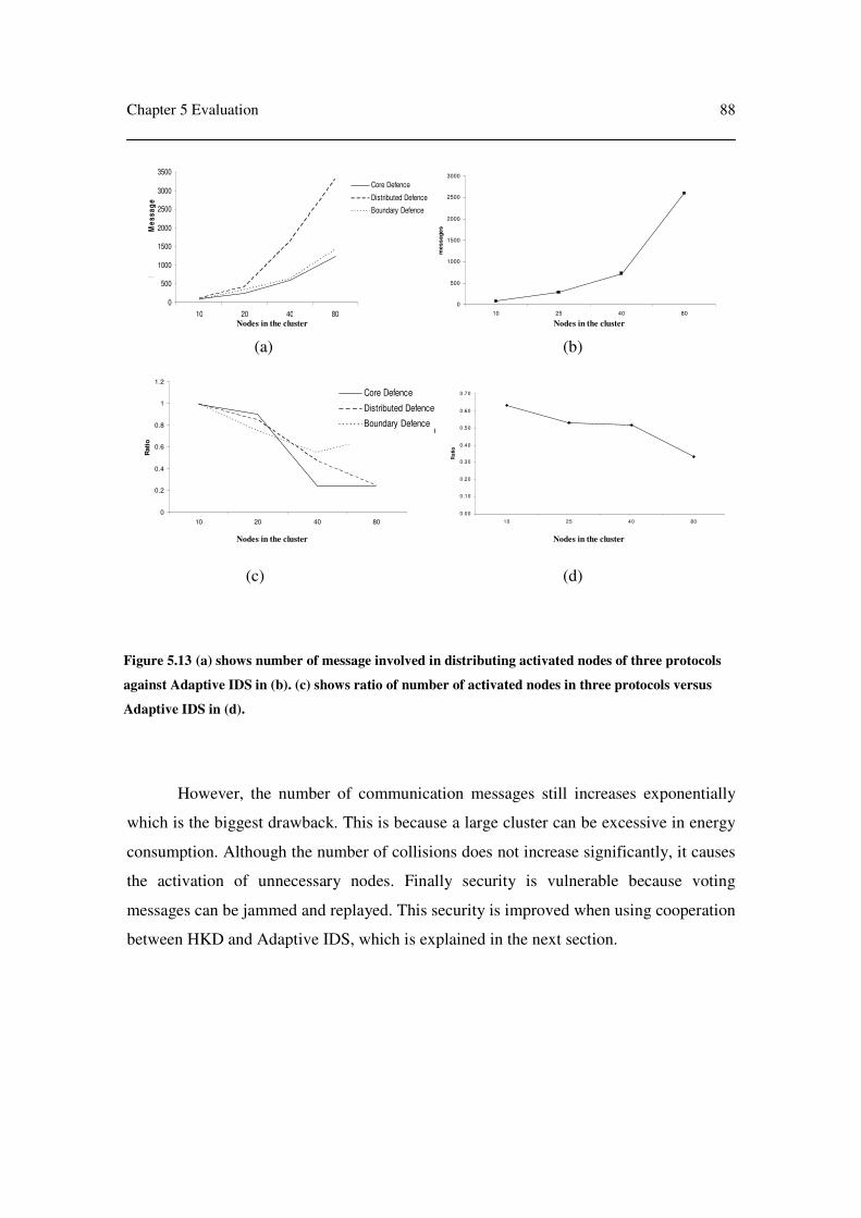
Chapter 5 Evaluation
88
However, the number of communication messages still increases exponentially
which is the biggest drawback. This is because a large cluster can be excessive in energy
consumption. Although the number of collisions does not increase significantly, it causes
the activation of unnecessary nodes. Finally security is vulnerable because voting
messages can be jammed and replayed. This security is improved when using cooperation
between HKD and Adaptive IDS, which is explained in the next section.
Figure 5.13 (a) shows number of message involved in distributing activated nodes of three protocols
against Adaptive IDS in (b). (c) shows ratio of number of activated nodes in three protocols versus
Adaptive IDS in (d).
0
500
1000
1500
2000
2500
3000
3500
10 20 40 80
No
. o
f A
lert
Me
ss
ag
e
Core Defence
Distributed Defence
Boundary Defence
0
500
1000
1500
2000
2500
3000
10 25 40 80
me
ss
ag
es
(a) (b)
0
0.2
0.4
0.6
0.8
1
1.2
10 20 40 80
Rati
o
Boundary Attack
Core Attack
Attack between Core and
Boundary
Core Defence
Distributed Defence
Boundary Defence
0.00
0.10
0.20
0.30
0.40
0.50
0.60
0.70
10 25 40 80
Ra
tio
(c) (d)
Nodes in the cluster
Nodes in the cluster
Nodes in the cluster
Nodes in the cluster

Chapter 5 Evaluation
89
5.3 Cooperation between HKD and Adaptive IDS
This section evaluates cooperation between HKD and Adaptive IDS compared
with non-cooperative protocol. We also define operational scenarios which are used in
the evaluation. Finally, a comparison of cooperative and static protocol is discussed and
analyzed.
5.3.1 Metrics of Performance
5.3.1.1 Energy Consumption
Since cooperation between HKD and Adaptive IDS is expected to reduce energy
usage in key management, energy consumption should be evaluated in order to compare a
cooperative and non-cooperative protocol. Energy consumption of operation is measured
from transmitting messages because it is the most energy intensive activity. In addition,
the effectiveness of dynamically updating keys in cooperative protocol should be
analyzed. In addition, Adaptive IDS should be evaluated with the energy consumption in
both cooperative and non-cooperative protocol. Since it is expected that a cooperative
protocol will enhance security, energy usage must be evaluated to compare the trade offs.
5.3.1.2 Security Strength
Cooperation between HKD and Adaptive IDS is expected to enhance the security
of the voting algorithm of Adaptive IDS. Therefore, the differences between a
cooperative and non-cooperative protocol should be evaluated. Since the voting
algorithm in Adaptive IDS is the most important for distributing activated nodes, an
adversary could attempt to attack this operation. Furthermore, if distribution is corrupted,
IDS in sensor networks could malfunction. In addition, a cooperative protocol could
affect security strength in both a safe and high-risk environment because the protocol
uses dynamic key updating.

Chapter 5 Evaluation
90
5.3.2 Parameters of Evaluation
5.3.2.1 Energy Consumption
System lifetime is a parameter in evaluating energy consumption for key
management. As dynamic key updating is based on the environment, different situations
could affect the system lifetime. Therefore, system lifetime of cooperative and non-
cooperative protocol should be compared. In addition, the number of transmitted
messages in cooperative protocol should be evaluated because an increase in security
strength in voting algorithm could affect energy usage. Although the number of activated
nodes causes significant energy consumption in Adaptive IDS, we neglect this fact in this
evaluation because a cooperative protocol does not change activating method.
5.3.2.2 Security Strength
Security strength on attacks is a parameter in evaluating Adaptive IDS. Since the
protocol is vulnerable against brute force, replay and jamming attacks, the protocol
should be analyzed. In addition, this parameter is useful for implementing the protocol. In
addition, we analyze brute force attack on cooperative protocol and compare to individual
HKD in different situations.
5.3.3 Evaluation Scenario
The system lifetime is calculated based on SmartDust node with the same
environment as in section 5.1.3. Power is supplied from a 3 volts battery with capacity
2,200 mAh. Our model sets up 10 nodes in each cluster and sample rate is 1 Hz with 50
Kbps bandwidth. Wireless communication consumes 4.8 mA in receiving and 12 mA in
transmitting. In idle mode, energy consumption rate is 5 µA.
The security strength is set up as in section 5.1.3. An adversary has an UltraSparc
II server with high performance antenna. This antenna can reach any part of the network
as well as transmitting and receiving messages. The power supply in this server is
unlimited.

Chapter 5 Evaluation
91
5.3.4 Performance Model
5.3.4.1 Energy Consumption
Theoretically, energy consumption should be significantly reduced in a safe
environment because each key can be used for a longer period. In a high-risk
environment, a cooperative protocol should consume more energy than a non-cooperative
protocol because it requires frequently exchanging and updating information.
In distributing activated node, energy consumption of the voting algorithm is
expected to be similar to a non-cooperative protocol because enhancing security in
Adaptive IDS uses encryption but transmitting messages does not change. Therefore, key
management is responsible for the security while the voting algorithm remains the same.
Consequently, the number of transmitted messages is still similar to the non-cooperative
protocol.
5.3.4.2 Security Strength
Cooperative protocol is expected to improve security in voting algorithm. Since
the original voting algorithm lacks verification and secrecy, the cooperative protocol
should be improved in critical attacks including brute force attack and replay attack.
In addition, the security of cooperative protocol is expected to have mixed results
because it acts differently in the different situations. In a safe environment, security
strength should be less strong than non-cooperative protocol. However, in a high-risk
environment the key is updated more frequently. Consequently, the system is more secure.
5.3.5 Evaluation
5.3.5.1 Energy Consumption
As shown in figure 5.14, the cooperative protocol is evaluated in three situations.
A safe environment is a situation in which no alerts are triggered and no suspicious
events are detected by IDS. Therefore, current key is used 50% longer. System lifetime of
cooperative protocol can increase by 22.2% compared to non-cooperative protocol
because of less frequent updating of keys and key chains. A high-risk environment is a
critical situation in which IDS triggers an alert signal thus key is updated more frequently

Chapter 5 Evaluation
92
as well as key chain. The result shows that energy usage increases significantly from key
and key chain updating. System lifetime is reduced by approximately 53% because key
chain updating requires more computation and battery as well as transmission of
messages in order to inform of an alert situation. A mixed situation is a combination of
50% risk situation and 50% safe situation. The result shows energy consumption
increases by 21.3% from non-cooperative protocol because risk situation consumes more
energy. Although safe situation can enhance system lifetime, sensor devices still need to
update key regularly. Therefore, cooperative protocol consumes 21.3% more power in
general situations.
Figure 5.15 supports a theoretical model in which the number of transmitting
messages in voting algorithm does not significantly change in cooperative protocol. Since
there is no change in algorithm, the cooperative protocol only encrypts voting message.
Therefore, there is no significant energy use in voting algorithm of cooperative protocol.
Protocol Message size
(bytes)
Estimated operation time
(days)
Cooperative protocol
(Safe Environment)
64 874
Cooperative protocol
(Risk Environment)
64 379
Cooperative protocol
(Mixed Environment)
64 563
HKD 64 715
Figure 5.14 Comparing a system lifetime between cooperative protocol and individual HKD.

Chapter 5 Evaluation
93
Number of Sent Messages
0
20
40
60
80
100
120
10 25 40 80
nodes in the cluster
me
ss
ag
es
(a)
Number of Sent Messages
0
20
40
60
80
100
120
10 25 40 80
nodes in the cluster
me
ss
ag
es
(b)
Figure 5.15 Graphs shows transmitted messages in (a) individual Adaptive IDS
(b) Cooperative protocol.

Chapter 5 Evaluation
94
5.3.5.2 Security Strength
In voting algorithm, Adaptive IDS does not have security protection from attacks.
In a cooperative protocol, replay attacks can be prevented by encrypting the voting
message with current key. In addition, the current key is changed more frequently than
IDS distribution. Therefore, current key is changed in every round of voting. If an
adversary attempts to perform a replay attack, the received node rejects the message
because the message is encrypted with the previous key. Therefore, the current key can
also be used for authentication. However, an adversary could attempt to do a replay
attack with voting message in the same round. The receiving node ignores the repeated
message because it is a duplicated vote. A vulnerability of the protocol is that an
adversary can use the voting message from one sub group to use in another sub group.
The worst result could be that more nodes are activated. Furthermore, the evaluation done
by brute force attack takes a long period of time to break the current key while voting is
completed in minutes so an adversary has no chance to create an imitated voting or
bidding message.
Security strengths of key management in simulation shows mixed results because
updating key is changed based on IDS information. Since the master key, key chain and
key size remain the same, key space of cooperative protocol is the same as HKD. A
difference is the frequency of key updating. In a high-risk environment, keys are updated
more frequently so adversaries have less chance to break the current key. Therefore, the
system is more secure. However, in safe situations keys are updated less frequently. This
could be a vulnerability that an adversary could exploit. Nevertheless, safe situation is
evaluated from non-suspicious event detected in which IDS ensures that no adversary in
current network. As shown in the simulation, the worst case for security in a cooperative
protocol is passive attack. Since an adversary does not perform any attacks, the network
assumes that it is a safe situation. Therefore, an adversary can use this situation to break
the key. Although brute force requires years to break the key, an adversary may use other
techniques to break the key over a longer period.

Chapter 5 Evaluation
95
5.4 Conclusion
This chapter evaluates HKD, Adaptive IDS and the cooperative protocol. The
simulation compares these protocols with related protocols where a number of different
parameters are used as benchmarks. The environment in simulation is set up based on
real data but it neglects unrelated factors for clarifying the result.
In summary, security strength of the current key in ELK, SPINS and HKD is
equivalent but SPINS enhances security in decrypting messages by using two keys. Key
chain in both SPINS and HKD is secured with larger key space which ensures a longer
computing time when brute force is used. In addition, the master key in HKD has the
largest key space which is the most secure key in these protocols. However, HKD does
not renew the master key regularly thus it could be vulnerable in the long term.
Furthermore, all three protocols only rely on the key so an adversary could harm the
network if the key is revealed. Finally, all three protocols are not able to resist denial of
service attacks.
ELK uses excessive resources especially memory and CPU which is infeasible to
implement in sensor devices because ELK uses asymmetric cryptography and does not
focus on minimizing resource usage. In SPINS, usage of memory and CPU is the least
among the three protocols followed by HKD and ELK respectively, while HKD uses the
least energy in communication. Therefore, HKD can enhance system lifetime the most
but still uses more memory and CPU processing than SPINS.
Adaptive IDS has an advantage in distributing activated nodes in the network.
Although Adaptive IDS distribution is not followed to an ideal model, it improves energy
consumption across the cluster. The coverage is better than static core and boundary
defense while it is equivalent to Agent-based IDS. In addition, the number of transmitted
messages increases linearly at O(n) because a tree hierarchy is not required. The number
of activated nodes also increases linearly thus the Adaptive IDS is scalable for a large
network. In addition, the ratio of activated nodes is reduced while node density increases
so energy in the cluster is reduced. To compare with Agent-based IDS, both the ratio and
the number of messages are improved because of its voting algorithm. However, the
number of communication messages still increases exponentially which is the biggest

Chapter 5 Evaluation
96
drawback because a large cluster can consume excessive energy. Finally, security is also
vulnerable because voting messages could be jammed and replayed.
A cooperative protocol consumes 21.3% more energy in general situations while
it increases security strength in alert situations. However, it is still vulnerable if an
adversary uses a passive attack because IDS cannot detect any suspicious activity. In
addition, the voting algorithm is more secure with secret key and there is no significant
energy usage in implementing security in this algorithm.

97
Chapter 6. Conclusion and Future Work
This thesis presents approaches to security in sensor networks which involves key
management and distributing Intrusion Detection System (IDS). The summarized thesis
work is described in a separated chapter. At the end of the chapter, we recommend future
work to improve the protocols.

Chapter 6 Conclusion and Future Work
98
6.1 Chapter One (Introduction)
A brief introduction to the wireless sensor network is provided, and then a
research method is presented to accomplish this thesis. An outline is also given with the
summary of key points as well as contributions by this thesis.
6.2 Chapter Two (Background)
Chapter two presents the general background of sensor networks and the
problems that are focused on in this thesis. A general definition of sensor network is
described with characteristics and restrictions. Even though the sensor network provides
advantages in self-organization, scalability, coverage, system lifetime and cost, it has
trade offs in limited resource in individual nodes. Then, the chapter explains a security
definition and cryptography as well as comparing both symmetric and asymmetric
cryptography. Its advantages and disadvantages are also discussed before describing
attacks. Since security is required to protect network from the attacks, understanding the
attacks can aid in evaluating the security solutions. The attacks need to be covered both
network attack and cryptography attack because network security should be protected
from numerous attacks. Finally, chapter explains IDS. The advantage of monitoring from
inside the network is that this can prevent attacks when adversaries break into the
network and prepare the network when external attacks are launched. However,
monitoring is an expensive task in sensor networks as well as the large coverage area is
difficult to install and maintain. These are the challenges that this thesis is focusing on.
6.3 Chapter Three (Literature Survey)
This chapter reviews existing protocols and solutions for problems in key
management and IDS for sensor network. Efficient Large-Group Key Distribution (ELK)
is a protocol that allows each node to compute an individual key from a hint message.
This hint message can reduce message size while not exposing any actual keys. However,
keys are generated from child nodes’ keys so a tree structure is required. Since sensor
networks are not reliable, tree structure maintenance could use an excessive amount of
energy. Security Protocols for Sensor Networks (SPINS) is a protocol designed for sensor

Chapter 6 Conclusion and Future Work
99
networks. Since communication consumes the most energy in sensor networks, SPINS
reduces the transmitted information. In addition, each node uses a key chain to enhance
security because adversaries cannot compute the key backward. In IDS, there is a lot of
research supporting the fact that IDS mechanism could operate in sensor networks.
However, challenges are reducing energy consumption and monitoring networks of a
large scale. Agent-based IDS proposes a solution by using voting algorithm. In each
round, every node sends a vote message to their gateway. Then, receiving nodes activate
IDS in their nodes. The result shows that selected node can cover the traffic of a network
as well as distribute the agent or activated node.
6.4 Chapter Four (Hint Key Distribution & Adaptive IDS)
In this thesis, we propose Hint Key Distribution (HKD) for key management and
Adaptive IDS for network monitoring.
HKD manages key distribution by using a base station to generate and broadcast
hint message. The hint message contains the hashed value of current key and current key
chain. Authorized nodes can construct a key from the hint message. Construction uses an
iterative computation of two one-way functions. The benefit is protecting against an
adversary computing the next key from the current key. In addition, HKD supports
joining nodes and packet loss because generating key from the hint message is stateless.
An important benefit in HKD is minimizing energy consumption in communication while
enabling base station to dynamically update keys based on the situations.
Adaptive IDS is a distributing system for IDS activated nodes in the network. As
distributed IDS enhances coverage and security, selected nodes should activate the IDS.
Adaptive IDS uses a voting algorithm with a threshold to select a high traffic node to
activate while avoiding repeatedly activating the same node. Since monitoring consumes
a lot of energy, repeatedly activating the same node could empty the battery quicker than
others. To make them usable in sensor networks, all nodes should have an equal lifetime.
Therefore, the threshold in Adaptive IDS ensures that uniform energy consumption in
IDS is maintained in the network. In addition, Adaptive IDS protocol consumes limited
energy in the voting procedure where transmitted message is on average two messages in
activated nodes and one message in non-activated nodes.

Chapter 6 Conclusion and Future Work
100
As a cooperative system, both HKD and Adaptive IDS can improve efficiency by
sharing information. HKD provides a management status and current activities. In
Adaptive IDS, there are four situations including normal situation, suspicious situation,
alert situation and extreme risk situation. The IDS activated node is required to inform
base station in suspicious, alert and extreme risk situations. To exchange information, in a
normal situation IDS does not detect any rules violation thus HKD can use the current
key for longer period to save energy. In a suspicious situation, IDS detects minor rules
violations so HKD updates current key regularly. In alert situation, IDS detects critical
violations and triggers the alarm so HKD updates key chains immediately. In an extreme
risk situation, IDS raises an alarm and HKD cannot update the key immediately so the
base station applies the strongest policy e.g. restarts the entire network.
6.5 Chapter Five (Evaluation)
This chapter evaluates HKD, Adaptive IDS and the cooperative protocol. In
summary, security strength of the current key in ELK, SPINS and HKD are equivalent
but SPINS enhances security in decrypting messages by using two keys. Key chain in
both SPINS and HKD is secured with larger key space which ensures a longer
computation time when brute force is used. In addition, master key in HKD has the
largest key space so it is the most secure key in these protocols. However, HKD does not
renew the master key regularly thus it could be vulnerable in the long term. Furthermore,
all three protocols only rely on the key so an adversary could do harm to the network if
the key is revealed. Finally, all three protocols are not able to resist denial of service
attacks. In terms of energy consumption, ELK uses an excessive amount of resources,
especially memory and CPU, which is infeasible to implement in sensor devices because
it uses asymmetric cryptography and does not focus on minimizing resource usage. In
SPINS, memory and CPU usages are the least among the three protocols. HKD is the
second best between ELK and SPINS in memory and CPU usage while using the least
energy in communication. Therefore, HKD can enhance system lifetime the most but still
uses more memory and CPU processing power than SPINS.

Chapter 6 Conclusion and Future Work
101
Adaptive IDS has an advantage in distributing activated nodes in the cluster.
Although distribution is not followed an ideal model, it improves energy consumption
across the cluster. The coverage of Adaptive IDS is equivalent to Agent-based IDS and
better than static core defense and boundary defense. The number of activated nodes
increases linearly thus scalability is supported in a large network. In addition, the ratio of
activated nodes is reduced while cluster size increases so energy in the cluster is also
reduced. To compare with Agent-based IDS, both ratio and number messages are
improved because of its voting algorithm. However, the number of communication
messages still increases exponentially which is the biggest drawback. This is because a
large cluster can consume excessive amounts of energy. Finally, security is also
vulnerable because voting messages can be jammed and replayed.
Cooperative protocol consumes more energy by 21.3% in a general situation but it
increases security strength in an alert situation. However, it is still vulnerable if an
adversary uses passive attack because IDS cannot detect any suspicious activity. In
addition, voting algorithm is more secured with a secret key and there is no significant
energy usage in implementing security in this algorithm.
6.6 Future Work
This section suggests the future work based on our proposed solution. In key
management, a cooperative protocol consumes significantly more energy in a risk
environment because key is updated quicker. Future work may consider threshold or
adaptive algorithm to adjust this situation. Although network is under attack, repeated
attacks in the long term may not require frequent updating of keys. However, there is a
challenge in this task because improving energy consumption normally decreases the
effectiveness of security. In addition, it can be difficult to predict different situations.
In distributing IDS, the proposed solution uses threshold number to distribute
energy consumption across the network. Future work may consider the amount of
remaining battery as a deciding factor. Since the main objective is using energy equally
in every node, battery is the best factor to measure. However, there are several challenges
in using these parameters. Standardization of hardware and battery could not be done
effectively across the entire network. A history of energy consumption does not enable

Chapter 6 Conclusion and Future Work
102
accurately predicting energy use in the future. Finally, battery does not release a
consistent amount of power. For example, 50% of remaining battery is not double the
capacity of 25% remaining battery in practice because chemistry and holding capacity of
battery is not ideal.

103
REFERENCES
[1] G. J. Pottie, "Wireless sensor networks," 1998, pp. 139-140.
[2] I. F. Akyildiz, W. Su, Y. Sankarasubramaniam, and E. Cayirci, "Wireless sensor
networks: a survey," Computer Networks, vol. 38, pp. 393-422, 2002.
[3] M. Tubaishat and S. Madria, "Sensor networks: an overview," Potentials, IEEE,
vol. 22, pp. 20-23, 2003.
[4] D. Culler, D. Estrin, and M. Srivastava, "Guest Editors' Introduction: Overview of
Sensor Networks," Computer, vol. 37, pp. 41-49, 2004.
[5] I. F. Akyildiz, S. Weilian, Y. Sankarasubramaniam, and E. Cayirci, "A survey on
sensor networks," Communications Magazine, IEEE, vol. 40, pp. 102-114, 2002.
[6] J. L. Wong and M. Potkonjak, "Search in sensor networks: challenges, techniques,
and applications," vol.4, pp. IV-3752-IV-3755, 2002.
[7] B. Alvise, P. C. Luca, and S. Alberto, "Platform based design for wireless sensor
networks," Mob. Netw. Appl., vol. 11, pp. 469-485, 2006.
[8] C. Alippi and G. Vanini, "Wireless sensor networks and radio localization: a
metrological analysis of the MICA2 received signal strength indicator," in 29th
Annual IEEE International Conference on Local Computer Networks, 2004, pp.
579-580.
[9] Crossbow, "Wireless Sensor Networks: Mica2 433, 868, 916 MHz," last visited
on 27/4/2007 [Online]. Available:
http://www.xbow.com/Products/productdetails.aspx?sid=174
[10] W. Dali, H. A. Chan, and B. Silombela, "Energy averaging schemes for ad hoc
wireless sensor networks," 2005, p. 7.
[11] D. Shangwei and Y. Xiaobu, "Exploring hierarchy architecture for wireless sensor
networks management," 2006, p. 6.
[12] W. R. Heinzelman, A. Chandrakasan, and H. Balakrishnan, "Energy-efficient
communication protocol for wireless microsensor networks," in Proceedings of
the 33rd Annual Hawaii International Conference on System Sciences, 2000, p.
10.
References
104
[13] W. Alec, T. Terence, and C. David, "Taming the underlying challenges of reliable
multihop routing in sensor networks," in Proceedings of the 1st international
conference on Embedded networked sensor systems, Los Angeles, California,
USA: ACM Press, 2003.
[14] B. Chen, K. Jamieson, H. Balakrishnan, and R. Morris, "Span: An Energy-
Efficient Coordination Algorithm for Topology Maintenance in Ad Hoc Wireless
Networks," Wireless Networks, vol. 8, pp. 481-494, 2002.
[15] K. Sohrabi, J. Gao, V. Ailawadhi, and G. J. Pottie, "Protocols for self-
organization of a wireless sensor network," Personal Communications, IEEE ,
vol. 7, pp. 16-27, 2000.
[16] G. J. Pottie and W. J. Kaiser, "Wireless integrated network sensors," Commun.
ACM, vol. 43, pp. 51-58, 2000.
[17] C. Jae-Hwan and L. Tassiulas, "Energy conserving routing in wireless ad-hoc
networks," in Proceedings of the 19th Annual Joint Conference of the IEEE
Computer and Communications Societies on INFOCOM, 2000, pp. 22-31.
[18] Y. Wei, H. John, and E. Deborah, "Medium access control with coordinated
adaptive sleeping for wireless sensor networks," IEEE/ACM Transactions on
Networking, vol. 12, pp. 493-506, 2004.
[19] P. Joseph, H. Jason, and C. David, "Versatile low power media access for wireless
sensor networks," in Proceedings of the 2nd international conference on
Embedded networked sensor systems Baltimore, MD, USA: ACM Press, 2004.
[20] A. Sinha and A. Chandrakasan, "Dynamic power management in wireless sensor
networks," Design & Test of Computers, IEEE, vol. 18, pp. 62-74, 2001.
[21] V. Raghunathan, C. Schurgers, P. Sung, and M. B. Srivastava, "Energy-aware
wireless microsensor networks," Signal Processing Magazine, IEEE, vol. 19, pp.
40-50, 2002.
[22] C. Schurgers, V. Tsiatsis, and M. B. Srivastava, "STEM: Topology management
for energy efficient sensor networks," in Aerospace Conference, IEEE, 2002, pp.
3-1099-3-1108.

References
105
[23] L. M. Thomas and P. S. Daniel, "The impact of battery capacity and memory
bandwidth on CPU speed-setting: a case study," in Proceedings of the 1999
international symposium on Low power electronics and design, San Diego,
California, United States: ACM Press, 1999, pp 200-205.
[24] T. L. Martin and D. P. Siewiorek, "Non-ideal battery properties and low power
operation in wearable computing," 1999, pp. 101-106.
[25] T. L. Martin and D. P. Siewiorek, "Nonideal battery and main memory effects on
CPU speed-setting for low power," IEEE Transactions on Very Large Scale
Integration (VLSI) Systems , vol. 9, pp. 29-34, 2001.
[26] R. Vijay, K. Aman, H. Jason, F. Jonathan, and S. Mani, "Design considerations
for solar energy harvesting wireless embedded systems," in Proceedings of the
4th international symposium on Information processing in sensor networks, Los
Angeles, California: IEEE Press, 2005.
[27] M. Alan, C. David, P. Joseph, S. Robert, and A. John, "Wireless sensor networks
for habitat monitoring," in Proceedings of the 1st ACM international workshop on
Wireless sensor networks and applications, Atlanta, Georgia, USA: ACM Press,
2002.
[28] K. Aman and B. S. Mani, "An environmental energy harvesting framework for
sensor networks," in Proceedings of the 2003 international symposium on Low
power electronics and design, Seoul, Korea: ACM Press, 2003.
[29] H. Jason, H. Mike, K. Ralph, and K. Lakshman, "The platforms enabling wireless
sensor networks," Commun. ACM, vol. 47, pp. 41-46, 2004.
[30] B. Duncan and D. Malan, "Low-Power, Secure Routing for MICA2 Mote.,"
Havard University Technical Report TR-06-04, 2004.
[31] A. Pohl, "A low-cost high-definition wireless sensor system utilizing intersymbol
interference," IEEE Transactions on Ultrasonics, Ferroelectrics and Frequency
Control, vol. 45, pp. 1355-1362, 1998.
References
106
[32] S. Eugene, C. Seong-Hwan, I. Nathan, M. Rex, S. Amit, W. Alice, and C.
Anantha, "Physical layer driven protocol and algorithm design for energy-
efficient wireless sensor networks," in Proceedings of the 7th annual
international conference on Mobile computing and networking, Rome, Italy:
ACM Press, 2001.
[33] H. Jason, S. Robert, W. Alec, H. Seth, C. David, and P. Kristofer, "System
architecture directions for networked sensors," in Proceedings of the 9th
international conference on Architectural support for programming languages
and operating systems, Cambridge, Massachusetts, United States: ACM Press,
2000.
[34] P. Seungmin, K. Jin Won, S. Kee-Young, and K. Daeyoung, "A nano operating
system for wireless sensor networks," in Proceedings of the 8th International
Conference on Advanced Communication Technology, 2006, p. 4.
[35] C. Bor-rong, M.-R. Kiran-Kumar, and W. Matt, "Ad-hoc multicast routing on
resource-limited sensor nodes," in Proceedings of the 2nd international workshop
on Multi-hop ad hoc networks: from theory to reality, Florence, Italy: ACM Press,
2006.
[36] L. Philip, L. Nelson, W. Matt, and C. David, "TOSSIM: accurate and scalable
simulation of entire tinyOS applications," in Proceedings of the 1st international
conference on Embedded networked sensor systems, Los Angeles, California,
USA: ACM Press, 2003.
[37] A. Dunkels, B. Gronvall, and T. Voigt, "Contiki - a lightweight and flexible
operating system for tiny networked sensors," in the 29th Annual IEEE
International Conference on Local Computer Networks, 2004, pp. 455-462.
[38] A. Eswaran, A. Rowe, and R. Rajkumar, "Nano-RK: an energy-aware resource-
centric RTOS for sensor networks," 2005, p. 10.
[39] C. Han, R. Kumar, R. Shea, E. Kohler, and M. Srivastava, "A Dynamic Operating
System for Sensor Nodes," in Proceedings of the 3rd international conference on
Mobile systems, applications, and services, 2005.

References
107
[40] S. Bhatti, J. Carlson, H. Dai, J. Deng, J. Rose, A. Sheth, B. Shucker, C.
Gruenwald, A. Torgerson, and R. Han, "MANTIS OS: An Embedded
Multithreaded Operating System for Wireless Micro Sensor Platforms," Mobile
Networks and Applications, vol. 10, pp. 563-579, 2005.
[41] M. H. Joseph, H. Wei, and R. M. Samuel, "The sensor spectrum: technology,
trends, and requirements," SIGMOD Rec., vol. 32, pp. 22-27, 2003.
[42] H. Balakrishnan, "Opportunities and challenges in high-rate wireless sensor
networking," in Proceedings of the 29th Annual IEEE International Conference
on Local Computer Networks, 2004, p. 4.
[43] S. Azadegan, M. Lavine, M. O. Leary, A. Wijesinha, and M. Zimand, "An
undergraduate track in computer security," in Proceedings of the 8th annual
conference on Innovation and technology in computer science education,
Thessaloniki, Greece: ACM Press, 2003.
[44] W. Thomas, "Security, privacy, and anonymity," Crossroads, vol. 11, p. 5, 2004.
[45] B. Imran, S. Enrico, and W. Kevin, "Securing network software applications:
introduction," Commun. ACM, vol. 44, pp. 28-30, 2001.
[46] S. Bruce, "Inside risks: Cryptography, security, and the future," Commun. ACM,
vol. 40, p. 138, 1997.
[47] S. V. Kartalopoulos, "A primer on cryptography in communications,"
Communications Magazine, IEEE, vol. 44, pp. 146-151, 2006.
[48] M. T. Sakalli, E. Bulus, and F. Buyuksaracoglu, "Cryptography education for
students," in Proceedings of the 5th International Conference on Information
Technology Based Higher Education and Training, 2004, pp. 621-626.
[49] K. G. David, "Cryptographic sealing for information secrecy and authentication,"
Commun. ACM, vol. 25, pp. 274-286, 1982.
[50] M. Pradosh Kumar, "Public key cryptography," Crossroads, vol. 7, pp. 14-22,
2000.
[51] H. Kevin, "Getting started with PGP," Crossroads, vol. 6, p. 8, 2000.

References
108
[52] H. Saputra, N. Vijaykrishnan, M. Kandemir, M. J. Irwin, R. Brooks, S. Kim, and
W. Zhang, "Masking the Energy Behavior of DES Encryption," in Design,
Automation and Test in Europe Conference and Exhibition, IEEE Computer
Society, 2003, p. 10084.
[53] F. Warwick, "Standardizing information technology security," StandardView, vol.
2, pp. 64-71, 1994.
[54] C. M. Ralph and E. H. Martin, "On the security of multiple encryption," Commun.
ACM, vol. 24, pp. 465-467, 1981.
[55] O. O. Khalifa, M. D. R. Islam, S. Khan, and M. S. Shebani, "Communications
cryptography," in RF and Microwave Conference, 2004, pp. 220-223.
[56] L. Susan, "Technical opinion: designing cryptography for the new century,"
Commun. ACM, vol. 43, pp. 115-120, 2000.
[57] O. Dino, B. Rainer, and H. Nevin, "AES and the cryptonite crypto processor," in
Proceedings of the 2003 International Conference on Compilers, Architecture
and Synthesis for Embedded Systems, San Jose, California, USA: ACM Press,
2003, pp 198 - 209.
[58] R. L. Rivest, A. Shamir, and L. Adleman, "A method for obtaining digital
signatures and public-key cryptosystems," Commun. ACM, vol. 21, pp. 120-126,
1978.
[59] I. Anshel, M. Anshel, and D. Goldfeld, "An algebraic method for public-key
cryptography," Mathematical Research Letters, vol. 6, 1999, pp 287-291.
[60] T. Elgamal, "A public key cryptosystem and a signature scheme based on discrete
logarithms," IEEE Transactions on Information Theory, vol. 31, pp. 469-472,
1985.
[61] H. Shai and K. Hugo, "Public-key cryptography and password protocols," ACM
Trans. Inf. Syst. Secur., vol. 2, pp. 230-268, 1999.
[62] E. Shimon, L. S. Alan, and Y. Yacov, "The complexity of promise problems with
applications to public-key cryptography," Inf. Control, vol. 61, pp. 159-173, 1984.
[63] W. Diffie, "The first ten years of public-key cryptography," in Proceedings of the
IEEE, vol. 76, pp. 560-577, 1988.
References
109
[64] D. Dolev and A. Yao, "On the security of public key protocols," IEEE
Transactions on Information Theory, vol. 29, pp. 198-208, 1983.
[65] K. Itoh, M. Takenaka, N. Torii, S. Temma, and Y. Kurihara, "Fast
Implementation of Public-Key Cryptography on a DSP TMS320C6201," in
Cryptographic Hardware and Embedded Systems: First International Workshop,
CHES'99, Worcester, MA, USA, 1999, pp. 726-726.
[66] C. M. Ralph, "Secure communications over insecure channels," Commun. ACM,
vol. 21, pp. 294-299, 1978.
[67] V. John and M. Matt, "Security is Harder than You Think," Queue, vol. 2, pp. 60-
65, 2004.
[68] M. N. Roger, "Denial of service: an example," Commun. ACM, vol. 37, pp. 42-46,
1994.
[69] G. N. Peter, "Inside Risks: denial-of-service attacks," Commun. ACM, vol. 43, p.
136, 2000.
[70] M. Long, W. Chwan-Hwa, and J. Y. Hung, "Denial of service attacks on network-
based control systems: impact and mitigation," IEEE Transactions on Industrial
Informatics, vol. 1, pp. 85-96, 2005.
[71] H. Yih-Chun, A. Perrig, and D. B. Johnson, "Wormhole attacks in wireless
networks," IEEE Journal on Selected Areas in Communications, vol. 24, pp. 370-
380, 2006.
[72] N. Hoang Lan and N. Uyen Trang, "Study of Different Types of Attacks on
Multicast in Mobile Ad Hoc Networks," in International Conference on
Networking, International Conference on Systems and International Conference
on Mobile Communications and Learning Technologies, 2006, pp. 149-149.
[73] C. Z. Cliff, T. Don, G. Weibo, and C. Songlin, "Routing Worm: A Fast, Selective
Attack Worm Based on IP Address Information," in Proceedings of the 19th
Workshop on Principles of Advanced and Distributed Simulation, IEEE Computer
Society, 2005.
[74] X. Wenyuan, M. Ke, W. Trappe, and Z. Yanyong, "Jamming sensor networks:
attack and defense strategies," Network, IEEE, vol. 20, pp. 41-47, 2006.

References
110
[75] L. Yee Wei, H. Lodewijk van, D. Jeroen, H. Pieter, and H. Paul, "Energy-efficient
link-layer jamming attacks against wireless sensor network MAC protocols," in
Proceedings of the 3rd ACM workshop on Security of ad hoc and sensor
networks, Alexandria, VA, USA: ACM Press, 2005.
[76] F. Anstett, G. Millerioux, and G. Bloch, "Chaotic Cryptosystems: Cryptanalysis
and Identifiability," IEEE Transactions on Circuits and Systems I: Regular
Papers, vol. 53, pp. 2673-2680, 2006.
[77] A. W. K. Kong, D. Zhang, and M. Kamel, "Analysis of Brute-Force Break-Ins of
a Palmprint Authentication System," IEEE Transactions on Systems, Man and
Cybernetics, Part B, vol. 36, pp. 1201-1205, 2006.
[78] J and R. rg, "Some facets of complexity theory and cryptography: A five-lecture
tutorial," ACM Comput. Surv., vol. 34, pp. 504-549, 2002.
[79] P. S. L. M. Barreto, V. Rijmen, J. N. Jr, B. Preneel, J. Vandewalle, and H. Y.
Kim, "Improved SQUARE Attacks Against Reduced-Round HIEROCRYPT," in
Fast Software Encryption: 8th International Workshop, FSE 2001 Yokohama,
Japan, April 2-4, 2001. Revised Papers, 2002, p. 165.
[80] D. Coppersmith, "The Data Encryption Standard (DES) and its strength against
attacks.," IBM Journal of Research & Development, vol. 38, p. 243, 1994.
[81] J. Kelsey, B. Schneier, and D. Wagner, "Mod n Cryptanalysis, with Applications
against RC5P and M6," in Fast Software Encryption: 6th International Workshop,
FSE'99, Rome, Italy, March, 1999, p. 139.
[82] S. Matthew, M. Carla, and S. Maureen, "Intrusion detection for distributed
applications," Commun. ACM, vol. 42, pp. 62-69, 1999.
[83] F. Stephanie, A. H. Steven, and S. Anil, "Computer immunology," Commun.
ACM, vol. 40, pp. 88-96, 1997.
[84] P. Brajendra and G. Joseph, "Defensive information warfare," Commun. ACM,
vol. 42, pp. 30-32, 1999.
[85] K. B. Lee and M. E. Reichardt, "Open standards for homeland security sensor
networks," Instrumentation & Measurement Magazine, IEEE, vol. 8, pp. 14-
21, 2005.

References
111
[86] E. Shi and A. Perrig, "Designing secure sensor networks," Wireless
Communications, IEEE, vol. 11, pp. 38-43, 2004.
[87] S. Slijepcevic, M. Potkonjak, V. Tsiatsis, S. Zimbeck, and M. B. Srivastava, "On
communication security in wireless ad-hoc sensor networks," in 11th IEEE
International Workshops on Enabling Technologies: Infrastructure for
Collaborative Enterprises, 2002, pp. 139-144.
[88] C. Chee-Yee and S. P. Kumar, "Sensor networks: evolution, opportunities, and
challenges," Proceedings of the IEEE, vol. 91, pp. 1247-1256, 2003.
[89] A. D. Wood and J. A. Stankovic, "Denial of service in sensor networks,"
Computer, vol. 35, pp. 54-62, 2002.
[90] P. Adrian, S. John, and W. David, "Security in wireless sensor networks,"
Commun. ACM, vol. 47, pp. 53-57, 2004.
[91] K. YoungMin, S. Sameer, M. Kirill, and A. Gul, "ActorNet: an actor platform for
wireless sensor networks," in Proceedings of the 5th International Joint
Conference on Autonomous Agents and Multiagent Systems, Hakodate, Japan:
ACM Press, 2006.
[92] B. Rahul, H. Chih-Chieh, R. Ram Kumar, T. Ilias, and S. Mani, "Multi-level
software reconfiguration for sensor networks," in Proceedings of the 6th ACM &
IEEE International Conference on Embedded Software, Seoul, Korea: ACM
Press, 2006.
[93] P. H. Chou and P. Chulsung, "Energy-efficient platform designs for real-world
wireless sensing applications," in Proceedings of the 2005 IEEE/ACM
International Conference on Computer-Aided Design, San Jose, CA: IEEE
Computer Society, 2005.
[94] A. Penrig, D. Song, and D. Tygar, "ELK, a new protocol for efficient large-group
key distribution," in Security and Privacy, Oakland, CA 2001, pp. 247-262.
[95] T. Sander and C. F. Tschudin, "Protecting Mobile Agents Against Malicious
Hosts," in Mobile Agents and Security, 1998, p. 44.
[96] D. Kundur and D. Hatzinakos, "Digital watermarking for telltale tamper proofing
and authentication," in Proceedings of the IEEE, vol. 87, pp. 1167-1180, 1999.
References
112
[97] I. J. Cox and J. P. M. G. Linnartz, "Some general methods for tampering with
watermarks," IEEE Journal on Selected Areas in Communications, vol. 16, pp.
587-593, 1998.
[98] J. Fridrich, "A hybrid watermark for tamper detection in digital images," in
Proceedings of the 5th International Symposium on Signal Processing and Its
Applications, 1999, pp. 301-304.
[99] I. J. Cox, M. L. Miller, and J. A. Bloom, "Watermarking applications and their
properties," in International Conference on Information Technology: Coding and
Computing, 2000, pp. 6-10.
[100] F. Hohl, "Time Limited Blackbox Security: Protecting Mobile Agents From
Malicious Hosts," in Mobile Agents and Security, 1998, p. 92.
[101] C. S. Collberg and C. Thomborson, "Watermarking, tamper-proofing, and
obfuscation - tools for software protection," IEEE Transactions on Software
Engineering, vol. 28, pp. 735-746, 2002.
[102] R. P. Nachiketh, R. Srivaths, R. Anand, and K. J. Niraj, "Analyzing the energy
consumption of security protocols," in Proceedings of the 2003 international
symposium on Low power electronics and design, Seoul, Korea: ACM Press,
2003.
[103] R. Sandro and H. David, "A survey of key management for secure group
communication," ACM Computing Surveys, vol. 35, pp. 309-329, 2003.
[104] W. Chung Kei, M. Gouda, and S. S. Lam, "Secure group communications using
key graphs," IEEE/ACM Transactions on Networking , vol. 8, pp. 16-30, 2000.
[105] M. J. Moyer, J. R. Rao, and P. Rohatgi, "A survey of security issues in multicast
communications," Network, IEEE, vol. 13, pp. 12-23, 1999.
[106] D. Wenliang, D. Jing, S. H. Yunghsiang, K. V. Pramod, K. Jonathan, and K.
Aram, "A pairwise key predistribution scheme for wireless sensor networks,"
ACM Transactions on Information and System Security, vol. 8, pp. 228-258,
2005.
[107] H. Lein, L. Hung-Yu, and X. Yongnan, "Cryptography for PC/workstation
security," ACM SIGICE Bulletin, vol. 20, pp. 21-26, 1994.
References
113
[108] W. Thomas, G. Jorge, and P. Christof, "Security on FPGAs: State-of-the-art
implementations and attacks," Transaction on Embedded Computing System, vol.
3, pp. 534-574, 2004.
[109] Z. Sencun, S. Sanjeev, and J. Sushil, "LEAP: efficient security mechanisms for
large-scale distributed sensor networks," in Proceedings of the 10th ACM
Conference on Computer and Communications Security, Washington D.C., USA:
ACM Press, 2003.
[110] Z. Sencun, S. Sanjeev, and J. Sushil, "Poster abstract: LEAP\—efficient security
mechanisms for large-scale distributed sensor networks," in Proceedings of the
1st International Conference on Embedded Networked Sensor Systems, Los
Angeles, California, USA: ACM Press, 2003.
[111] P. Adrian, S. Robert, J. D. Tygar, W. Victor, and E. C. David, "SPINS: security
protocols for sensor networks," Wireless Network, vol. 8, pp. 521-534, 2002.
[112] M. Y. Huang, R. J. Jasper, and T. M. Wicks, "A large scale distributed intrusion
detection framework based on attack strategy analysis" in Computer Networks,
1999, pp. 2465-2475.
[113] K. Ilgun, "Unstat: A real-time intrusion detection system for unix," Proc of IEEE
Computer Society Symp on Research in Security and Privacity, May 1993.
[114] K. Ilgun, R. A. Kemmerer, and P. Porras, "State transition analysis: A rule-based
intrusion detection approach," in IEEE Transactions on Software Engineering,
1995, pp. 181-199.
[115] S. Kumar and E. H. Spafford, "A software architecture to support misuse
intrusion detection," in National Information Systems Security Conference, 1995,
pp. 194-204.
[116] V. Paxon, "Bro: A system for detecting network intruders in real-time," in
Proceedings of the 7th Conference on USENIX Security Symposium, 1998, p. 3.
[117] P. A. Porras and P. G. Neumann, "Emerald: Event monitoring enabling responses
to anomalous live disturbances," in Proceedings of 20th NIST-NCSC National
Information Systems Security conference, 1997, pp. 353-365.

References
114
[118] H. Yi-an and L. Wenke, "A cooperative intrusion detection system for ad hoc
networks," in Proceedings of the 1st ACM Workshop on Security of Ad hoc and
Sensor Networks, Fairfax, Virginia: ACM Press, 2003.
[119] T. Chin-Yang, B. Poornima, K. Calvin, L. Rattapon, R. Jeff, and L. Karl, "A
specification-based intrusion detection system for AODV," in Proceedings of the
1st ACM Workshop on Security of Ad hoc and Sensor Networks, Fairfax, Virginia:
ACM Press, 2003.
[120] R. d. S. Ana Paula, H. T. M. Marcelo, P. S. R. Bruno, A. F. L. Antonio, B. R.
Linnyer, and W. Hao Chi, "Decentralized intrusion detection in wireless sensor
networks," in Proceedings of the 1st ACM International Workshop on Quality of
service & security in wireless and mobile networks, Montreal, Quebec, Canada:
ACM Press, 2005.
[121] G. Chao and M. Prasant, "Power conservation and quality of surveillance in target
tracking sensor networks," in Proceedings of the 10th Annual International
Conference on Mobile Computing and Networking, Philadelphia, PA, USA: ACM
Press, 2004.
[122] D. Olivier, T. Christina, and T. Patrick, "Delay of intrusion detection in wireless
sensor networks," in Proceedings of the 7th ACM International Symposium on
Mobile Ad hoc Networking and Computing, Florence, Italy: ACM Press, 2006.
[123] Z. Yongguang and L. Wenke, "Intrusion detection in wireless ad-hoc networks,"
in Proceedings of the 6th Annual International Conference on Mobile Computing
and Networking, Boston, Massachusetts, United States: ACM Press, 2000.
[124] D. Dasgupta and H. Brian, "Mobile security agents for network traffic analysis,"
in DARPA Information Survivability Conference & Exposition II, vol.2, pp. 332-
340, 2001.
[125] M. C. Bernardes and E. dos Santos Moreira, "Implementation of an intrusion
detection system based on mobile agents," in International Symposium on
Software Engineering for Parallel and Distributed Systems, 2000, pp. 158-164.
[126] G. Helmer, J. S. K. Wong, V. Honavar, L. Miller, and Y. Wang, "Lightweight
agents for intrusion detection," Journal of Systems and Software, vol. 67, pp. 109-
122, 2003.

References
115
[127] T. Jiang, J.-R. Liu, and Y. Qin, "The research on dynamic self-adaptive network
security model based on mobile agent," in the 36th International Conference on
Technology of Object-Oriented Languages and Systems, 2000, pp. 134-139.
[128] O. Kachirski and R. Guha, "Effective intrusion detection using multiple sensors in
wireless ad hoc networks," in Proceedings of the 36th Annual Hawaii
International Conference on System Sciences, 2003, p. 8.
[129] O. Kachirski and R. Guha, "Intrusion detection using mobile agents in wireless ad
hoc networks," in IEEE Workshop on Knowledge Media Networking, 2002, pp.
153-158.
[130] P. Soo-Chang and Z. Yi-Chong, "Tamper proofing and attack identification of
corrupted image by using semi-fragile multiple-watermarking algorithm," in
Proceedings of the 2006 ACM Symposium on Information, Computer and
Communications Security, Taipei, Taiwan: ACM Press, 2006.
[131] B. Feng, "Multimedia content protection by cryptography and watermarking in
tamper-resistant hardware," in Proceedings of the 2000 ACM Workshops on
Multimedia, Los Angeles, California, United States: ACM Press, 2000.
[132] T. Clark, N. Jasvir, S. Ram, and H. Charles, "Tamper-proofing software
watermarks," in Proceedings of the 2nd workshop on Australasian information
security, Data Mining and Web Intelligence, and Software Internationalisation,
Dunedin, New Zealand: Australian Computer Society, Inc., 2004.
[133] "Smart dust research project homepage," last visited on 15/06/2006 [Online].
Available: http://robotics.eecs.berkeley.edu/~pister/SmartDust/
[134] M. Horton and J. Suh, "A vision for wireless sensor networks," in Microwave
Symposium Digest, IEEE MTT-S International, 2005, p. 4 .
[135] J. M. Kahn, R. H. Katz, and K. S. J. Pister, "Mobile Networking for Smart Dust,"
in CM/IEEE International Conference on Mobile Computing and Networking,
Seattle, WA, 1999.
[136] K. S. J. Pister, J. M. Kahn, and B. E. Boser, "Smart Dust: Wireless Networks of
Millimeter-Scale Sensor Nodes," Electronics Research Laboratory Research
Summary, 1999.

References
116
[137] V. Hsu, J. M. Kahn, and K. S. J. Pister, "Wireless Communications for Smart
Dust," Electronics Research Laboratory Technical Memorandum, vol. M98/2,
1998.
[138] L. Yung-Hsiang, L. Benini, and G. De Micheli, "Dynamic frequency scaling with
buffer insertion for mixed workloads," IEEE Transactions on Computer-Aided
Design of Integrated Circuits and Systems, vol. 21, pp. 1284-1305, 2002.
[139] S. K. Srinivasan and M. N. Velev, "Formal verification of an Intel XScale
processor model with scoreboarding, specialized execution pipelines, and impress
data-memory exceptions," in Proceedings of the 1st ACM and IEEE International
Conference on Formal Methods and Models for Co-Design, 2003, pp. 65-74.
[140] V. Raghunathan, C. L. Pereira, M. B. Srivastava, and R. K. Gupta, "Energy-aware
wireless systems with adaptive power-fidelity tradeoffs," IEEE Transactions on
Very Large Scale Integration (VLSI) Systems, vol. 13, pp. 211-225, 2005.
[141] L. T. Clark, E. J. Hoffman, J. Miller, M. Biyani, L. Luyun, S. Strazdus, M.
Morrow, K. E. Velarde, and M. A. Yarch, "An embedded 32-b microprocessor
core for low-power and high-performance applications," IEEE Journal of Solid-
State Circuits, vol. 36, pp. 1599-1608, 2001.
[142] A. Bogliolo, L. Benini, E. Lattanzi, and G. De Micheli, "Specification and
analysis of power-managed systems," in Proceedings of the IEEE, vol. 92, pp.
1308-1346, 2004.
[143] ISIS, "Prowler Probailistic Wireless Network Simulator," last visited on
28/06/2007 [Online]. Available:
http://www.isis.vanderbilt.edu/Projects/nest/prowler/
[144] G. Prasanth, V. Ramnath, P. Pushkin, D. Alexander, M. Frank, and S. Mihail,
"Analyzing and modeling encryption overhead for sensor network nodes," in
Proceedings of the 2nd ACM international conference on Wireless sensor
networks and applications, San Diego, CA, USA: ACM Press, 2003.

References
117
[145] S. S. Bhattacharyya, C. Brooks, E. Cheong, I. John Davis, M. Goel, B. Kienhuis,
E. A. Lee, M.-K. Leung, J. Liu, X. Liu, L. Muliadi, S. Neuendorffer, J. Reekie, N.
Smyth, J. Tsay, B. Vogel, W. Williams, Y. Xiong, Y. Zhao, H. Zheng, and G.
Zhou, "PTOLEMY II heterogeneous concurrent modeling and design in java,"
UCB/EECS-2007-7, vol. 6, 2007.
[146] G. Simon, P. Volgyesi, M. Maroti, and A. Ledeczi, "Simulation-based
optimization of communication protocols for large-scale wireless sensor
networks," 2003, pp. 3_1339-3_1346.
[147] "ISIS - Prowler," last visited on 14/06/2007 [Online]. Available:
http://www.isis.vanderbilt.edu/Projects/nest/prowler/
[148] L. He, L. Xiaojun, and E. A. Lee, "Modeling distributed hybrid systems in
Ptolemy II," in Proceedings of American Control Conference, 2001, pp. 4984-
4985.
[149] P. Baldwin, S. Kohli, E. A. Lee, L. Xiaojun, and Z. Yang, "Modeling of sensor
nets in Ptolemy II," in the 3rd International Symposium on Information
Processing in Sensor Networks, 2004, pp. 359-368.
[150] X. Yuhong, E. Leet, L. Xiaojun, Z. Yang, and L. C. Zhong, "The design and
application of structured types in Ptolemy II," in IEEE International Conference
on Granular Computing, 2005, pp. 683-688.
[151] L. Rui, L. Renfa, and W. Jigang, "A Ptolemy II Based Modeling Approach for
Context-Aware Computing," in the 1st International Symposium on Pervasive
Computing and Applications, 2006, pp. 27-31.


![A Hybrid Framework for Building an Efficient Incremental ...€¦ · signature-based intrusion detection system. In [22], a hierarchical layering distributed intrusion detection system](https://img.dokumen.tips/doc/110x75/5f0e49c67e708231d43e8385/a-hybrid-framework-for-building-an-efficient-incremental-signature-based-intrusion.jpg)