Embed Size (px)
Citation preview
C o m p a c t Disc Test I n s t r u m e n t s CATALOG
KENWOOD CORPORATION
KENWO
OD

Generates Signals Equivalent to a CD P CD Encoder
The DA-3500A Compact Disc Encoder is a CD format reference signal generator. It generates signals that are equivalent to a CD player laser pickup output.
The DA-3500A generates EFM signals for every type of signal source that are completely compatible with CD standards, performs CIRC processing and adds complete subcodes that include R-W codes. This gives the DA-3500A all the functions needed to edit lead-in data for discs. In addition to its highly useful functions as a
disc-cutting tool, the DA-3500A generates all the test signals needed in the inspecting and adjusting of CD players. External control of all functions through the internal GP-IB interface means automatic, energy-saving production, inspection and adjustment of CD players and functional testing of CD ICs. • Uses the internal R-W subcode-adaptor
to perform arithmetic/logic operations, which conform to CD standards, on data from the screen editor.
• Since the DA-3500A uses its MTF approximation characteristic filter and applies jitter modulation, AM modulation and offset disturbance, it can generates a complete set of simulation signals, including those for the optical transmission system.
• T h e DA-3500A generates highly precise, low-distortion, 16-bit digital signals for measuring D-A converter and bandpass filter characteristics in CD players.
R-W subcode-adaptor
Inserting the RW-3500 into the DA-3500 option slot allows the RW-3500 to interleave and parity-add R-W data that conform to
CD standards. The RW-3500 sends that data from a screen editor, used with the PC-100 [NEC personal computer), or from another device, to the DA-3500 subcode section. • Use of a peak format written in image-
data-send time, called TIME PACK, permits image data received from an external source to be sent at any time.
• Contains two bank memories [32K bytes
each] that allow data to be written f rom an external source and, simultaneously, data to be transferred to the DA-3500 subcode section.
• S i n c e this adaptor will also receive data from personal computers other than screen editors using the PC-100, it can be used to create software and hardware as prescribed by the data format and timing chart.
ACCESSORIES: Instruction manual 1 copy 50-pin connector [Ampheno l type) 1 pc
TEST INSTRUMENTS
DA-3500A
RW-3500
layer Laser Pickup Output. SPECIFICATIONS
Options: CB-2420P GP-IB Cable
2
CODE FORMAT: Conforms with Compact Disc Standards (February 1985 edition)
S Y N C H R O N O U S S IGNALS : C L O C K Frequency: 8.6436MHz internal or external (TTL LEVEL) switching External Input Range: 8.6436MHz ± 1 MHz
RF S I G N A L OUTPUT: RF signal output, 2 systems TTL Level Output Pins: Output by positive logic TTL level
(Pull-up 330n , Pull-down 330n ) for jitter modulat ion only
Variable Output RF Signal Output Pins: Variable range: 0 to 1 Vp-p (with 7 5 n load)
E F M S I G N A L SOURCE: Sinewave, triangular wave, square wave, M-series pseudorandom signal and external digital data input. Two systems. Digital setting of frequency and level for sine, triangular and square waves.
Sine, Triangular and Square Waves:
Frequency Range: Sine and square waves: 1 Hz to 22.049kHz, set in 1 Hz steps. Triangular wave: 1 Hz to 11.024kHz, set in 1 Hz steps.
Frequency Stability: Based on standard clock stability Rate cf Distorticn: Digital distortion of 0.0015% or less. Output Variable Range: Oto 1 0 0 % s e t i n 0 . 1 % s t e p s a n d 0 t o - 8 4 d B s e t i n 0 . 1 d B
steps down to —60dB, set in 1dB steps at less than - 6 0 d B .
Level Setting Accuracy: 0.004% or no greater than 0.1dB (to - 6 0 d B ) , or no greater than 1dB (to - 8 4 d B ) .
M-Series Pseudcrandcm Signal:
Random data: 8 bits Initialization: Can be PRESET O N / O F F
Digital Data Inputs 1: Input Data Format: 8-bit units (by high-byte, low-byte sampl ing)
positive logic 2's complement Uses: For DC-3510 A-D converter photoisolation input
and other uses Digital Data Input 2:
Input Data Format: 8 bit-units (by high-byte, low-byte sampl ing) positive logic 2's complement
Uses: For DT-3520 digital I/O input and TTL level input Pseudo Error Pattern Generat ion: Pre-Error (Before EFM Modulat ion)
Error Type: C1 correctable errors C2 correctable errors Corrected (concealed) error External burst errors due to EX-OR operations on drop-in signals.
3 os t Error (After Frame Generat ion):
Error Type: C1 correctable errors C2 correctable errors Corrected (concealed) errors External burst errors due to A N D / O R operations on drop-in signals, Errors due tooptionally set error patterns (under GP-IB control) .
Error Pattern Set: Segments of 108 frames divided in bit units.
T R A N S M I S S I O N S IMULATION SYSTEM: Applies jitter modulat ion, AM modulat ion, MTF approximat ion filter and DC offset to RF signals for the simulation of transmission circuits.
Jitter Modulation: Modulation Factor: 0 to 7% Modulation Frequency
Range: 10Hz to 9.99kHz Modulation Waves: Sinewave, tr iangular wave, square wave and external
External Modulation Factor: 7%/2Vp-p
AM Modulation: Modulation Factor: 0 to 100% Internal Modulation
Frequency Range: 10Hz to 9.99kHz Modulation Waves: Sinewave, triangular wave, square wave and external External Modulation
Factor: 100%/2Vp-p External Modulation
Frequency Range: DC to 50kHz Offset Addit ion:
Added Voltage: 0 to ±0.5V ( 7 5 n load; external input voltage, 0 t o ± 1 V p e a k )
External Input Frequency Range: DC to 50kHz
MTF Approximat ion Filter: Filter Selection: Can be turned ON and OFF Filter Type: 4th order approximating elliptical filter
MUTING: Right and left channels can be digitally-muted, independently.
SUBCODE C O N F I G U R A T I O N : P and Q Subcode
Test Patterns: PROM contains variable test patterns for P and Q subcodes.
R-W Subcodes: Can be externally input CUTTING: By connect ing the DA-3500A to a disc cutter,
it can cut discs in CD standard format. READ-OUT: 20-digit display by 5 x 7 dot matrix LEDs. EXTERNAL CONTROL: Can externally control all funct ions required for
operations through the GP-IB (IEEE Std 488 1978) interface.
D I M E N S I O N S : 4 3 0 ( W ) X 1 4 9 ( H ) X 4 6 5 ( D ) m m WEIGHT: Approx. 12kg POWER R E Q U I R E M E N T S :
1 0 0 / 1 2 0 / 2 2 0 / 2 4 0 V AC, 50 /60Hz Approx. 100W ACCESSORIES: Instruction manual 1 copy
Power code 1 pc C a b l e ( C A - 4 1 ) 2 p c s Cable (CA-43) 1 pc 50-pin connector (Ampheno l type) 1 po Spare fuse
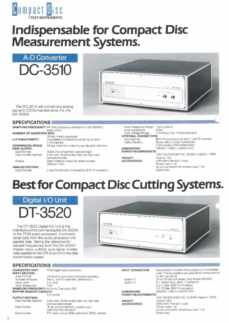
Indispensable for Compact Disc Measurement Systems.
A-D Converter
DC-3510
The DC-3510 will convert any analog signal to CD format and send it to the DA-3500A.
SPECIFICATIONS Input Frequency Range: 1 Hz to 20kHz Input Impedance: 3 3 k n Input Voltage Range: 1.1414Vp-p (for 1Vrms sinewave)
EXTERNAL C O N N E C T O R S : Input Section: BNC-R connectors for both L and R channels. Output Section: 50-pin micro-r ibbon connectors
(DDK model 57FE-40500-20S) D I M E N S I O N S : 4 3 0 ( W ) x 1 4 9 ( H ) x 4 6 5 ( D ) m m POWER R E Q U I R E M E N T S :
100/1 20 /220 /240V AC, 50/60HZ Approx. 100W WEIGHT: Approx. 7kg ACCESSORIES: Instruction manual 1 copy
Power code 1 pc 50-pin connector (Ampheno l type) 1 pc Spare fuse
Best for Compact Disc Cutting Systems. Digital I/O Unit
DT-3520 The DT-3520 Digital I/O Unit is the
interface unit forconnecting the DA-3500A to the PCM audio processor. It converts serial data from the audio processor into parallel data. Taking the reference for sample frequencies from the DA-3500A master clock, a 60Hz, sync signal is externally applied to the VTR to synchronize data transmission speed.
SPECIFICATIONS
TEST INSTRUMENTS
S A M P L I N G FREQUENCY: 44.1 kHz (frequency-divided f r om DA-3500A's basic clock).
N U M B E R O F Q U A N T I Z E D BITS: 16 bits, linearly quantized.
L/R SIMULTANEITY: Completely simultaneous sampling for both L/R channels.
C O N V E R S I O N SPEED: 14.5/is max imum including sample-and-hold time. DATA OUTPUT:
Data Format: 16-bit, 2's complement , positive logic. Data Transfer Method: 8-bit units, 16-bit configurat ion by high-byte,
low-byte transfer. Output: Open-collector output by photo-coupler
(BVceo=15V) A N A L O G SECTION:
Input Circuits: L and R channels connected by BNC-R connector.
C O N N E C T E D UNIT: PCM digital audio-processor INPUT SECTION:
Input Format: 1 6-bit serial data synchronized to sampl ing. Number of Inputs: Two (L and Ft) channels, parallel input. Input Level: TTL level Input Impedance: 7 5 n
S A M P L I N G FREQUENCY: 44.1kHz Duty cycle 50% B U F F E R M E M O R Y CAPACITY:
512 words OUTPUT SECTION:
Data Transfer Method: 8-bit units, 16-bit configuration by high-byte and low-byte transfer.
Data Format: 16-bit, 2's complement , positive logic (with EIAJ format input)
Output Level: TTL level, pull-up 3 3 0 n , pul l -down 390 f i , internal.
3
INPUT C O N N E C T O R : Input section consists of two systems of connected units. The two systems are selected by using a switch on the rear panel.
System 1: 25-pin D-sub connector (JAE Model DB-25S) System 2: 2 -1 . World Sync: BNC-R connector
2-2. L Data: BNC-R connector 2-3. R Data: BNC-R connector
D I M E N S I O N S : 4 3 0 ( W ) x 1 4 9 ( H ) x 4 6 5 ( D ) m m POWER R E Q U I R E M E N T S :
1 0 0 / 1 2 0 / 2 2 0 / 2 4 0 V AC, 50 /60HZ Approx. 100W WEIGHT: Approx. 6kg ACCESSORIES: Instruction manual 1 copy
Power code 1 pc 50-pin connector (Ampheno l type) 1 pc Spare fuse
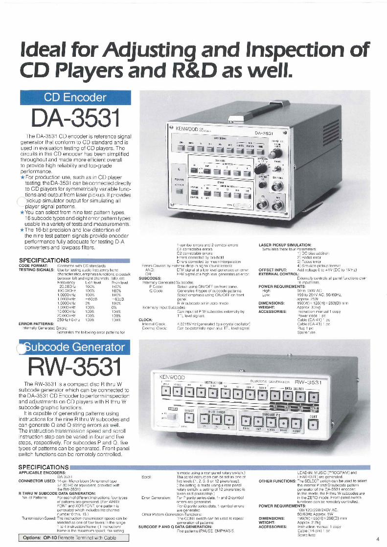
Ideal for Adjusting and Inspection of CD Players and R&D as well.
CD Encoder
DA-3531
1-symbol errors and 2-symbol errors C1 correctable errors C2 correctable errors Errors corrected by pre-hold Errors corrected by mean interpolation
Errors Caused by External drop-in signal (burst errors]: AND: EFM signal at a low level generates an error. OR: EFM signal at a high level generates an error,
SUBCODES: Internally Generated Subcodes:
P Code: Select using ON/OFF on front panel. Q Code: Generates 4 types of subcode patterns.
Select emphasis using ON/OFF on front panel. R-W subcode set in zero mode.
Externally Input Subcodes: Can input all P-W subcodes externally by TTL level signals.
CLOCK: Internal Clock: 4 3218MHz (generated by a crystal oscillator] External Clock: Can be-externally input as a TTL level signal.
LASER PICKUP SIMULATION: Simulates these four Parameters:
1) DC bias addition 2] Radial error 3) Focus error 4) Simulate-pickup format
OFFSET INPUT: Add voltage 0 to ^ 1V (DC to 1 MHz] EXTERNAL CONTROL:
Externally controls all panel functions over 16 input lines.
POWER REQUIREMENTS: High: 90 to 130V AC Low: 1 98 to 264V AC, 50/60Hz,
approx. 25W DIMENSIONS: t 90[W) X 1 28[H] x 263(D] mm WEIGHT: Approx. 3.2kg ACCESSORIES: Instruction manual 1 copy
Power code 1 pc Cable (CA-41] 1 pc Cable (CA-43) 1 pc Plug 1 pc Spare fuse
Bubcode Generator
RW-3531 The RW-3531 is a compact disc R thru W
subcode generator which can be connected to the DA-3531 CD Encoder to perform inspection and adjustments on CD players with R thru W subcode graphic functions.
It is capable of generating patterns using instructions for the nine R thru W subcodes and can generate Q and Q string errors as well. The instruction-transmission speed and scroll instruction step can be varied in four and five steps, respectively. For subcodes P and Q, five types of patterns can be generated. Front-panel switch functions can be remotely control led.
is made using a rear-panel rotary switch.) Scroll: The scroll instruction can be set as one of
five levels (1, 2, 3, 6 or 12 pixels/step). (The setting is made using a rear-panel rotary switch; a setting of 12 pixels/step is taken as 6 pixels/step.)
Error Generation; For P parity series data, 1 - and 2-symbol errors are generated For O parity series data, 1 -symbol errors are generated.
Other Pattern-Generation Functions: The CONT switch can be used to repeat generation of patterns,
SUBCODE P AND Q DATA GENERATION: Five patterns (PAUSE. EMPHASIS,
LEAD-IN, MUSIC (PROGRAM) and LEAD-OUT) are generated.
OTHER FUNCTIONS: The SELECT switch can be used to select the internal P and Q subcode pattern generator of the DA-3531 encoder. In this mode, the R thru W subcodes are in the ZERO mode. Front-panel switch functions can be remotely controlled.
POWER REQUIREMENTS: 1O0/120/220/24OV AC, 50/60HZ Approx. 5W
DIMENSIONS: 190(W)x65(H)x260(D) mm WEIGHT: Approx. 2.2kg ACCESSORIES: Instruction manual 1 copy
Cable (14-pin) 1 pc Spare fuse
The DA-3531 CD encoder is reference signal generator that conform to CD standard and is used in evaluation testing of CD players. The circuits in this CD encoder has been simplified throughout and made more efficient overall to provide high reliability and top-grade performance. • For production use, such as in CD player
testing, the DA-3531 can be connected directly to C D players for symmetrically variable functions and output f rom laser pickup. It provides )ickup simulator output for simulating all player signal patterns.
• You can select f rom nine test pattern types, 16 subcode types and eight error pattern types usable in a variety of tests and measurements.
• The 16-bit precision and low distortion of the nine test pattern signals provide encoder performance fully adequate for testing D-A converters and lowpass filters.
SPECIFICATIONS CODE FORMAT: Conforms with CD standards TESTING SIGNALS: Use lor testing audio frequency band
characteristics, emphasis functions, crosstalk between left and right channels, IMD. etc. Frequency L-ch level R-ch level 20.000Hz 100% 100%
100 000Hz 100% 100% 10000kHz 100% 100% 10000kHz -60dB -60dB 1.0000kHz 0% 100% 1.0000kHz 100% 0% 10.000kHz 100% 100% 20.000kHz 100% 100% 250Hz+8kHz 100% 100%
ERROR PATTERNS: Internally Generated Errors:
Generates the following error patterns tor
APPLICABLE ENCODERS: DA-3531
CONNECTOR USED: 14-pin Mlcrorlbbon CAmphenol type 57-30140 or equivalent: provided with the RW-3531)
R THRU W SUBCODE DATA GENERATION: No. of Patterns: For each of different instructions, four types
of patterns are generated. [For WRITE FONT and XOR FONT, one pattern is generated which includes the channel number 0 thru 15.)
Transmission Speed: The instruction-transmission speed can be selected as one of four levels in the range 1 to 4 instruction/frame. [1 instruction/ frame is the maximum speed; the setting
| Opt ions: OP-10 Remote Terminal with Cable |
SPECIFICATIONS
Used for Adjusting Azimuth and Servo CD Jitter Analyzer
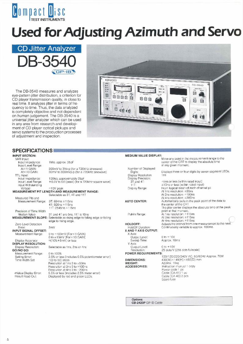
DB-3540 The DB-3540 measures and analyzes
eye-pattern jitter distribution, a criterion tor CD player transmission quality, in close to real time. It analyzes jitter in terms of frequency to time. Thus, the data analyzed is completely objective and not dependent on human judgement. The DB-3540 is a universal jitter analyzer which can be used in any area f rom research and development of CD player optical pickups and servo systems to the production processes of adjustment and inspection.
SPECIFICATIONS
Opt ions: CB - 2420PGP- IB Cable
TEST INSTRUMENTS
INPUT SECTION: VAR Input:
Input Impedance: 1 M n , approx. 35pF Input Level Range:
A t x 1 GAIN: 3 0 0 m V to 3Vp-p (for a 720kHz sinewave) A t x 10 GAIN: 30mV to 300mVp-p (for a 720kHz sinewave)
TTL Input: Input Impedance: 10Okn, approximately 35pF Input Level Range: +0 .5V to 5V (peak) (for a 720kHz square wave) Input Withstanding
Voltage: ± 10V peak M E A S U R E M E N T PIT L E N G T H A N D M E A S U R E M E N T RANGE:
Selectable as 3T, 4T and 11T Measured Pits and
Measurement Range: 3T: 694ns ±115ns 4T: 926ns ±115ns 11T: 2545ns ±115ns
Precision of Time Width Median Value: 3T and 4T are 5ns, 11T is 10ns
M E A S U R E M E N T SLOPE: Selectable as rising edge to falling edge or falling edge to rising edge.
Zero Level Detection Error: 3mV
INPUT S IGNAL OFFSET: Measurement Range; 0 to ± 1 0 0 m V ( F o r x 1 GAIN)
0 t o ± 1 0 m V ( F o r x 1 0 G A I N ) Display Accuracy: ± ( 1 0 % + 5 m V ) or less
DISPLAY R E S O L U T I O N : Display Resolution: Selectable as 1 ns, 2ns or 4ns
G O / N O GO: Measurement Range: 0 to 100% Setting Error: 2.5% or less (includes 0.5% potentiometer error) T ime Width Set: ± (0 to 50) steps
Resolution at 1 ns 0 to ±50ns Resolution at 2ns 0 to ±100ns Resolution at 4ns 0 to ±200ns
<rValue Display Error: 5.5% or less (includes 2.5% meter error) Result Read-Out: Displayed by red and green LEDs.
M E D I U M VALUE DISPLAY: Move any point in the measurement range to the center of the CRT to display the absolute t ime at any given moment .
Number of Displayed Digits: Displays three or four digits by seven-segment LEDs.
Display Resolution: 1 ns Display Precision:
3T and 4T: ±5ns or less (within rated input) 11T: ±10ns or less (within rated input)
Display Range: From logical mean of each channel pit At 1 ns resolution: ±95ns At 2ns resolution: ±190ns At 4ns resolution: ±380ns
AUTO CENTER: Automatically pulls in the peak point of the data to the center of the CRT. The jitter center displays the absolute t ime of the peak point at that moment .
Pull-In Range: At 1 ns resolution: ±115ns At 2ns resolution: ±115ns At 4ns resolution: ±115ns
H O L D O F F : Adjusts the interval f rom one measurement to the next. HoldOff Duration: Continuously variable to approx. 100ms.
X A N D Y AXIS OUTPUT: X Axis:
Output Level: 0 t o + 1 0 V Sweep Time: Approx. 10ms
Y Axis: Output Level: 0 t o + 1 0 V Resolution: 25 dots/V (255 dots fullscale)
POWER R E Q U I R E M E N T S : 100 /120 /220 /240V AC, 50 /60HZ Approx. 70W
D I M E N S I O N S : 4 3 0 ( W ) x 1 4 9 ( H ) x 4 6 5 ( D ) m m WEIGHT: Approx. 11kg ACCESSORIES : Instruction manual 1 copy
Power code 1 pc Cable (CA-41) 1 pc Cable (CA-43) 2 pes Spare fuse
5
System of CD Players. CD Jitter Analyzer
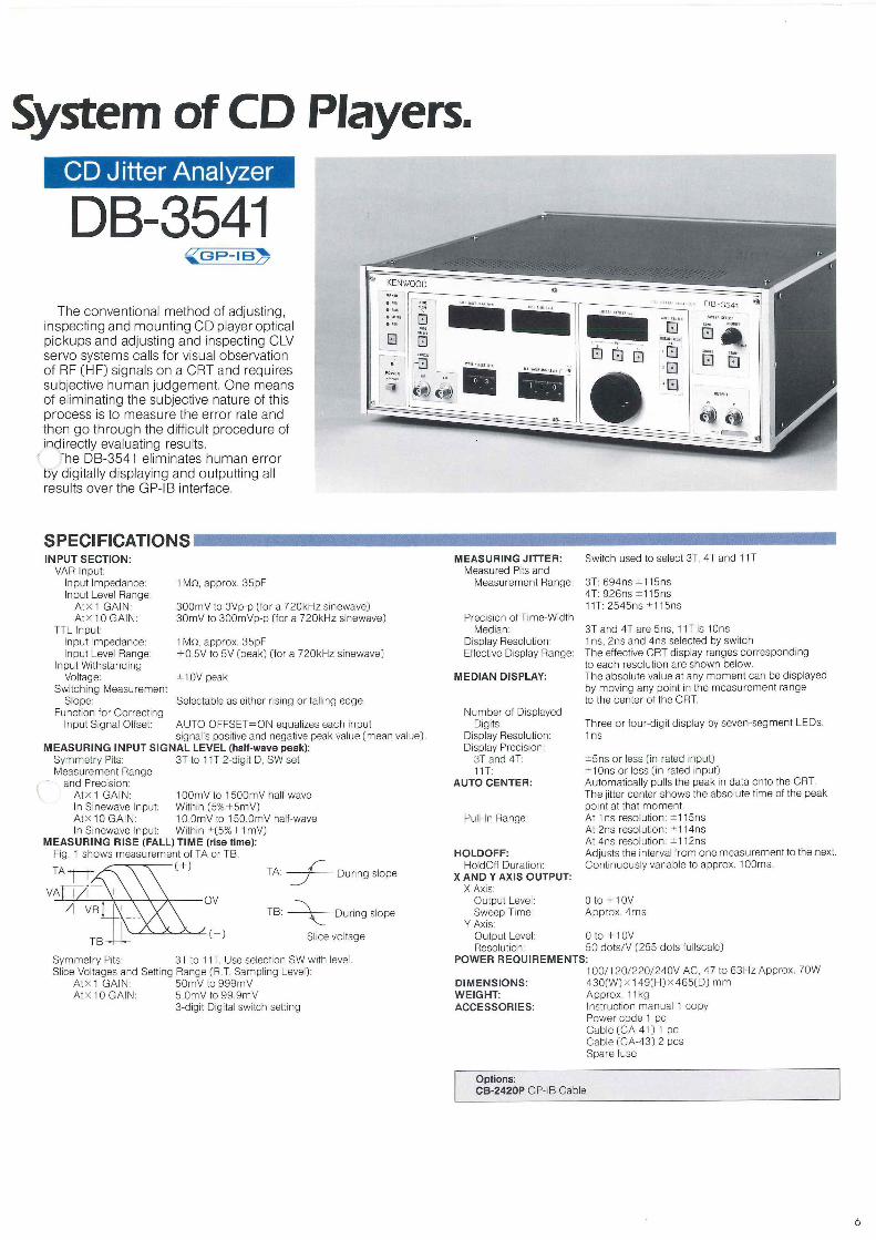
DB-3541 The conventional method of adjusting,
inspecting and mounting CD player optical pickups and adjusting and inspecting CLV servo systems calls for visual observation of RF (HF) signals on a CRT and requires subjective human judgement. One means of eliminating the subjective nature of this process is to measure the error rate and then go through the difficult procedure of indirectly evaluating results.
"he DB-3541 eliminates human error by digitally displaying and outputting all results over the GP-IB interface.
SPECIFICATIONS M E A S U R I N G JITTER: Switch used to select 3T, 4T and 11T
Measured Pits and Measurement Range: 3T: 694ns ±115ns
4T: 926ns ±115ns 11T: 2545ns ±115ns
Precision of Time-Width Median: 3T and 4T are 5ns, 11T is 10ns
Display Resolution: 1 ns, 2ns and 4ns selected by switch Effective Display Range: The effective CRT display ranges corresponding
to each resolution are shown below. M E D I A N DISPLAY: The absolute value at any momen t can be displayed
by moving any point in the measurement range to the center of the CRT.
Number of Displayed Digits: Three or four-digit display by seven-segment LEDs.
Display Resolution: 1 ns Display Precision:
3T and 4T: ±5ns or less (in rated input) 11T: ± 10ns or less (in rated input)
AUTO CENTER: Automatically pulls the peak in data onto the CRT. The jitter center shows the absolute t ime of the peak point at that moment .
Pull-ln Range: At 1 ns resolution: ±115ns At 2ns resolution: ±114ns At 4ns resolution: ±112ns
HOLDOFF: Adjusts the interval f rom one measurement to the next. HoldOff Duration: Cont inuously variable to approx. 100ms.
X A N D Y AXIS OUTPUT: X Axis:
Output Level: 0 t o + 1 0 V Sweep Time: Approx. 4ms
Y Axis: Output Level: 0 t o + 1 0 V Resolution: 50 dots/V (255 dots fullscale)
POWER R E Q U I R E M E N T S : 1 0 0 / 1 2 0 / 2 2 0 / 2 4 0 V AC, 47 to 63Hz Approx. 70W
D I M E N S I O N S : 4 3 0 ( W ) x 1 4 9 ( H ) X 4 6 5 ( D ) m m WEIGHT: Approx. 11kg ACCESSORIES: Instruction manual 1 copy
Power code 1 pc Cable (CA-41) 1 pc Cable (CA-43) 2 pes Spare fuse
Options: CB-2420P GP-IB Cable
INPUT SECTION: VAR Input:
Input Impedance: 1 Mn , approx. 35pF Input Level Range:
A t x 1 GAIN: 300mV to 3Vp-p (for a 720kHz sinewave) A t x 10 GAIN: 30mV to 300mVp-p (for a 720kHz sinewave)
TTL Input: Input Impedance: 1 M n , approx. 35pF Input Level Range: +0 .5V to 5V (peak) (for a 720kHz sinewave)
Input Withstanding Voltage: ±10V peak
Switching Measurement Slope: Selectable as either rising or falling edge
Function for Correct ing Input Signal Offset: AUTO OF F S E T =ON equalizes each input
signal's positive and negative peak value (mean value). M E A S U R I N G INPUT S I G N A L LEVEL (half-wave peak):
Symmetry Pits: 3T to 11T 2-digit D, SW set Measurement Range
and Precision: A t x 1 GAIN: 1 0 0 m V t o 1500mV half-wave In Sinewave Input: Within ( 5%+5mV) A t x 10 GAIN: 10 .0mVto 150.0mV half-wave In Sinewave Input: Within ± (5%+1 mV)
M E A S U R I N G RISE (FALL) T IME (rise t ime): Fig. 1 shows measurement of TA or TB.
Symmetry Pits: 3T to 11T. Use selection SW with level. Slice Voltages and Setting Range (R.T Sampl ing Level):
A t x 1 GAIN: 50mV to 999mV A t x 10 GAIN: 5.0mV to 99 .9mV
3-digit Digital switch setting
Dur ing slope
During slope
Slice voltage
6
Ideal for Playback and Error Measurement of EFM Signals Including Graphics Information,
CD Decoder
DR-3550A
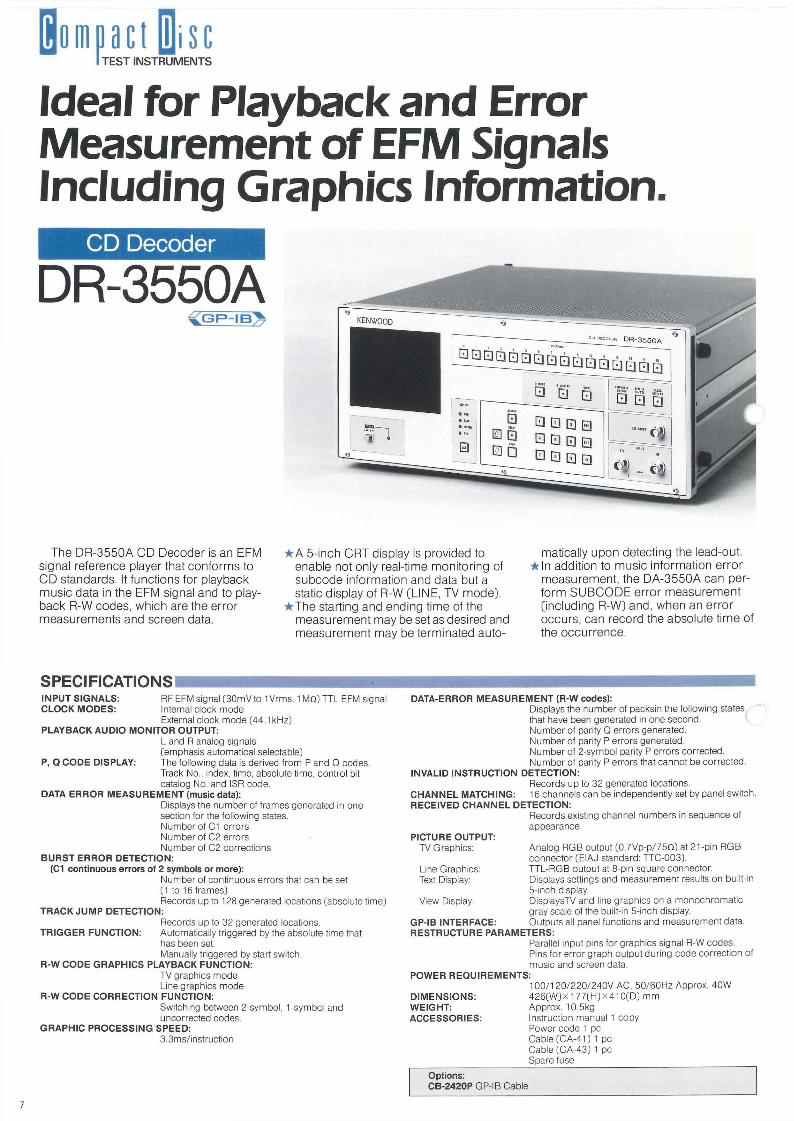
The DR-3550A CD Decoder is an EFM signal reference player that conforms to CD standards. It functions for playback music data in the EFM signal and to playback R-W codes, which are the error measurements and screen data.
• A 5-inch CRT display is provided to enable not only real-time monitoring of subcode information and data but a static display of R-W [LINE, TV mode],
• The starting and ending time of the measurement may be set as desired and measurement may be terminated auto
matically upon detecting the lead-out. • In addition to music information error
measurement, the DA-3550A can perform SUBCODE error measurement [including R-W] and, when an error occurs, can record the absolute time of the occurrence.
SPECIFICATIONS DATA-ERROR M E A S U R E M E N T (R-W codes):
Displays the number of packsin the following states that have been generated in one second. Number of parity Q errors generated. Number of parity P errors generated. Number of 2-symbol parity P errors corrected. Number of parity P errors that cannot be corrected.
INVALID INSTRUCTION DETECTION: Records up to 32 generated locations.
C H A N N E L MATCHING: 16 channels can be independently set by panel swi tch. RECEIVED C H A N N E L DETECTION:
Records existing channel numbers in sequence of appearance.
PICTURE OUTPUT: TV Graphics: Analog RGB output (0 .7Vp-p /75n) at 21-pin RGB
connector (EIAJ standard: TTC-003). Line Graphics: TTL-RGB output at 8-pin square connector. Text Display: Displays settings and measurement results on built-in
5-inch display. View Display: DisplaysTV and line graphics on a monochromat ic
gray scale of the built-in 5-inch display. GP-IB INTERFACE: Outputs all panel funct ions and measurement data. RESTRUCTURE PARAMETERS:
Parallel input pins for graphics signal R-W codes. Pins for error graph output dur ing code correct ion of music and screen data.
POWER R E Q U I R E M E N T S : 1 0 0 / 1 2 0 / 2 2 0 / 2 4 0 V AC, 50 /60Hz Approx. 40W
D I M E N S I O N S : 426 (W)X 1 7 7 ( H ) x 4 1 0 ( D ) m m WEIGHT: Approx. 10.5kg ACCESSORIES: Instruction manual 1 copy
Power code 1 pc Cable (CA-41) 1 pc Cable (CA-43) 1 pc Spare fuse
Options: CB-2420P GP-IB Cable
TEST INSTRUMENTS
INPUT S IGNALS : RF EFM signal (30mV to 1 Vrms, 1 M n ) TTL EFM signal CLOCK M O D E S : Internal clock mode
External clock mode (44.1 kHz) PLAYBACK AUDIO MONITOR OUTPUT:
L and R analog signals (emphasis automatical selectable)
P, Q C O D E DISPLAY: The following data is derived f rom P and Q codes. Track No., index, t ime, absolute t ime, control bit catalog No. and ISR code.
DATA ERROR M E A S U R E M E N T (music data): Displays the number of f rames generated in one section for the following states. Number of C1 errors Number of C2 errors Number of C2 correct ions
B U R S T ERROR DETECTION: (C1 con t inuous errors of 2 symbols or more):
Number of cont inuous errors that can be set (1 to 16 frames) Records up to 128 generated locations (absolute t ime)
TRACK J U M P DETECTION: Records up to 32 generated locations.
TRIGGER FUNCTION: Automatically triggered by the absolute time that has been set. Manually triggered by start switch.
R-W C O D E GRAPHICS PLAYBACK FUNCTION: TV graphics mode Line graphics mode
R-W CODE CORRECTION FUNCTION: Switching between 2-symbol, 1-symbol and uncorrected codes.
G R A P H I C P R O C E S S I N G SPEED: 3.3ms/instruct ion
7
Tests the Graphics Mode of the R-W Subcodes.
Subcode Test Disc
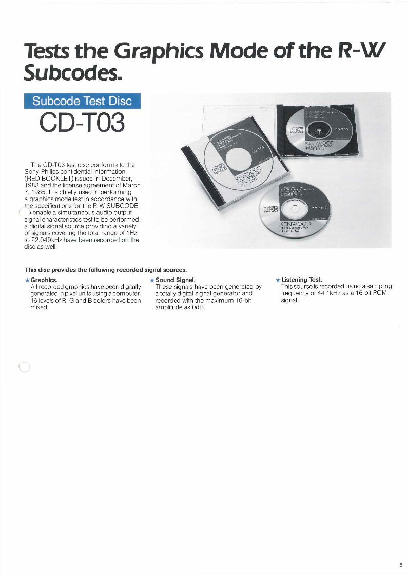
CD-T03 The CD-T03 test disc conforms to the
Sony-Philips confidential information [RED BOOKLET] issued in December, 1983 and the license agreement of March 7, 1985. It is chiefly used in performing a graphics mode test in accordance with the specifications for the R-W SUBCODE.
> enable a simultaneous audio output signal characteristics test to be performed, a digital signal source providing a variety of signals covering the total range of 1 Hz to 22.049kHz have been recorded on the disc as well.
This disc provides the following recorded signal sources. • Graphics.
All recorded graphics have been digitally generated in pixel units using a computer. 16 levels of R, G and B colors have been mixed.
• Sound Signal. These signals have been generated by a totally digital signal generator and recorded with the maximum 16-bit amplitude as OdB.
• Listening Test. This source is recorded using a sampling frequency of 44.1kHz as a 16-bit PCM signal.
8

TEST INSTRUMENTS
CD Player Configuration and Operating Principal. This section will serve to describe the configuration and operation of a CD player. • RF Amplifier
The RF Amplifier is used to derive the quadrature RF signal which includes the focus information f rom the laser pickup, the FOCUS signal and the TRACKING signal (and the difference between the leading and trailing spots for three-beam systems).
• Pick-Up Servo This section performs laser pick-up focusing and pit tracking using the FOCUS and TRACKING signals which are part of the RF signal.
• Bit Detector This section establishes RF signal symmetry and converts the RF signal to a logic signal.
• Clock Generator This circuit section generates a 4.3218MHz transmission clock from the EFM signal using a PLL.
• Sync Detector This section extracts the [11 bi t+11 b i t+2 bit] FRAME sync signal [7.35kHz] f rom the RF signal using the generated CLOCK. This signal is used as the timing reference for signal processing.
• CLV Servo Since compact discs are recorded using a constant linear velocity, it is necessary to
constantly change the spindle motor rpm to compensate for the varying disc radius. The spindle motor servo is controlled so that the FRAME sync signal is always 7.35kHz.
• DE-EFM This section restores the original 8-bit data from the 14-bit (EFM) data converted f rom the 8-bit data recorded onto the disc.
• Error Correction Even when random reading errors caused by disc defects and damage or burst errors occur, the compact disc system is designed to eliminate as much as possible any adverse effects on the playback signal. The error correction process consists of determining whether or not an error in data exists, making a calculation based on the data before and after the error and actually correcting or interpolating for the erroneous data.
• Channel Separation Since recorded data is dispersed throughout the disc, the left and right channels are not separated. The left and right channel data must, therefore, be separated using the sync signal to establish the proper timing relationships.
• D-A Converter At the digital-to-analog converter, the left channel and right channel data are converted to analog signals by sampling at a given
frequency. • Low-Pass Filter
This 20Hz low-pass filter is used to eliminate the aliasing noise which occurs according to information theory.
• Sub-Decoder The 8-bit "CONTROL & DISPLAY" symbol which follows the FRAME sync pattern is termed the SUBCODE. These 8 bits [Bits P-W] are extracted and decoded according to the disc format. The P signal is used for information between musical selections and the Q signal is used for t ime and emphasis information. R-W are graphics signals.
• Control & Display These are unique operating features of the CD player, and consist of storage of disc contents according to the lead-in data, display of processing times, display of absolute time, random access and trick play.
• Error Correction (R-W) The 8 (R-W) bits of the SUBCODE consist of graphics data and these bits have an in herent error correcting capacity as well. T K . is done by means of bits P and Q and a CRC [Cyclic Redundancy Code] .
• Graphics Control The LINE graphics signal and TV graphics signal are separated and instructions for the various modes are executed.
Block Structure of Typical CD Player
SPINDLE ' MOTOR
LASER PICK-UP
RF AMP
FOCUS SERVO
TRACKING SERVO
BIT DETECTION
CLOCK REGENERATOR
DE-EFM
SYNC DETECTOR
CLV SERVO
ERROR CORREC
TION
CHANNEL SEPARA
TION DAC S/H
SUBCODE DECODER
ERROR CORREC
TION GRAPHIC CONTROL
CONTROL & DISPLAY
DE-EMPHASIS
CHANNEL SWITCH
9
LPF DE-EMPHASIS
Lch ANALOG
OUT
Roh ANALOG
OUT LPF S/H DAC
R-W
LINE GRAPHICS OUT
TV GRAPHICS OUT
P. Q
7 . 3 5 k H z

CD Cutting System This section will serve to describe the process of cutting a compact disc and the operation of the various equipment used.
Time Code Generator This section generates the lead-in information, lead-out information and P and Q signals in real time.
* Graphic Editor This section uses the Q information from the ENCODER to generate the R-W SUBCODE which comprise GRAPHICS information. It alone generates the TV graphics mode and LINE graphics mode pictures.
* PCM VCR/VTR This section generates the master tape which
serves as a sound source from PCM recorded digital data.
* Audio Processor This section extracts f rom the VIDEO signal (from the VCR or VTR) digital data and the required recording control signals (e.g., EMPHASIS signal).
* Digital Interface This section formats the various signals from the AUDIO PROCESSOR to match the ENCODER.
* Encoder This encoder performs the processing necessary to format music data from the SUBCODE and digital I/O data which include graphics
information, and performs synchronization and DSV calculations to derive the complete CD signal.
* Decoder The decoder serves as a real-time monitor during the cutting process and monitors all recorded data while measuring errors during recording.
• Laser Cutter This device uses a laser modulated by the on/off switching of the EFM signal f rom the ENCODER to record data onto the glass master onto which an a luminum layer has been sputtered.
CD Cutting Process
Time Code Generator
PCM VCR/VTC
Graphics Editor
Digital Interface
Audio Processor
Laser Cutting
• Monitoring
Glass Master" • Stamper •
Protection Shell Printing CD
CD Cutting System
U-MATIC VCR
PC-100 S-100
Audio Processor PCM-1610
Analog Signals
Monitor Scope
CD Player
Cutting Monitor
TV
Amp.
l O
Decoder
Encoder Stamp Aluminium
Coating Press
DA-3500A
DT-3520
DC-3510
CD Cutting
DR-3550A

KENWOOD CORPORATION INTERNATIONAL MARKETING DIVISION
TEST & MEASURING INSTRUMENT DEPARTMENT SHIONOGI SHIBUYA BLDG..
17-5. 2-CHOME, SHIBUYA, SHIBUYA-KU, TOKYO 150, JAPAN CABLE: KENWOOD TOKYO TELEX: 242-3446 KENWD FAX: 486-5749
•Specifications and design subject to change without notice for improvements.
U-3001 1986.10.20CAP20] Printed in Japan.
KENWO
OD