Embed Size (px)
Citation preview
Revised: 7/28/15
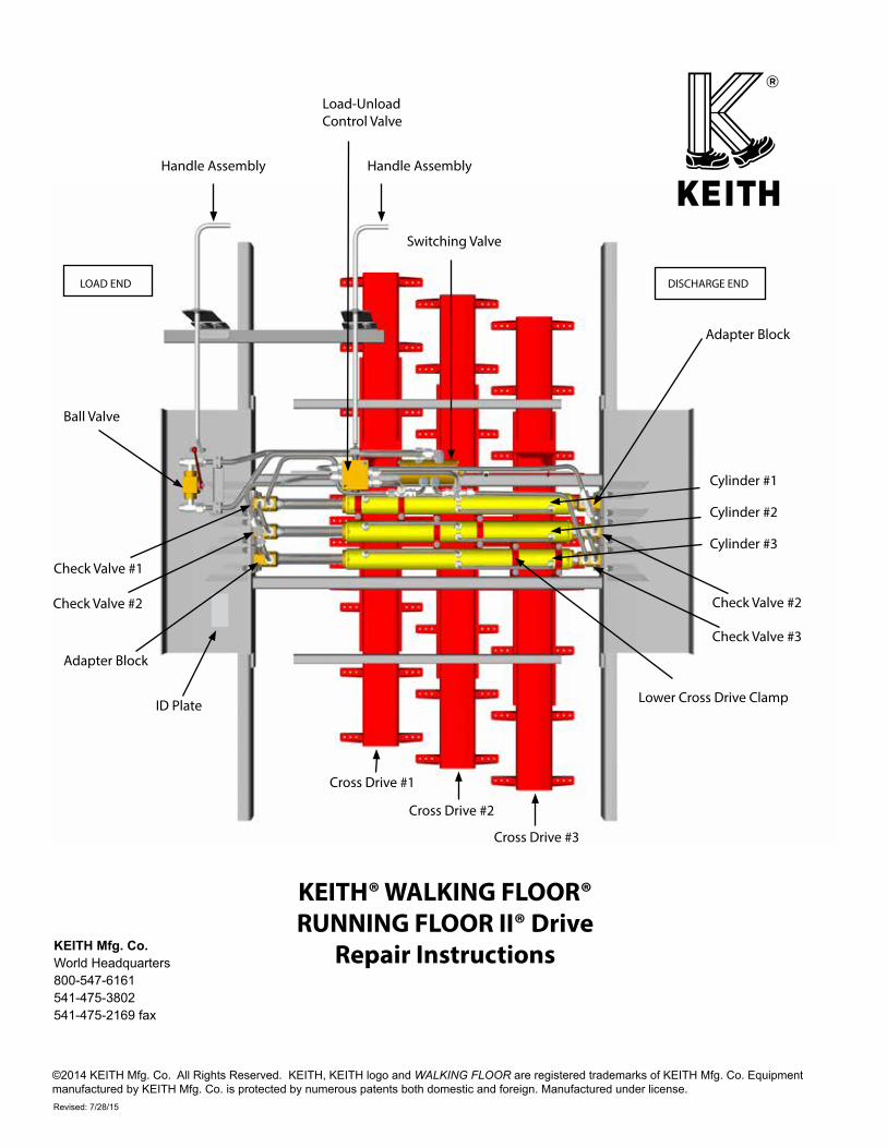
KEITH® WALKING FLOOR®RUNNING FLOOR II® Drive
Repair Instructions
©2014 KEITH Mfg. Co. All Rights Reserved. KEITH, KEITH logo and WALKING FLOOR are registered trademarks of KEITH Mfg. Co. Equipment manufactured by KEITH Mfg. Co. is protected by numerous patents both domestic and foreign. Manufactured under license.
KEITH Mfg. Co.World Headquarters800-547-6161541-475-3802541-475-2169 fax
Cylinder #1
Cylinder #2
Cylinder #3
Load-Unload Control Valve
Check Valve #2
Switching Valve
Check Valve #1
Check Valve #2
Check Valve #3
Cross Drive #1
Cross Drive #2
Cross Drive #3
Ball Valve
ID Plate Lower Cross Drive Clamp
Adapter Block
Handle Assembly Handle Assembly
Adapter Block
LOAD END
DISCHARGE END
Page 1
RUNNING FLOOR II® Drive Repair Instructions
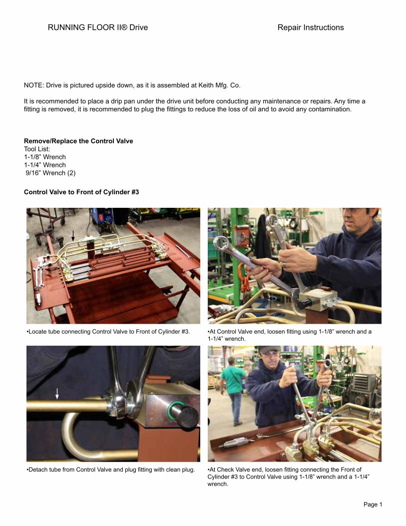
NOTE: Drive is pictured upside down, as it is assembled at Keith Mfg. Co.
It is recommended to place a drip pan under the drive unit before conducting any maintenance or repairs. Any time a fitting is removed, it is recommended to plug the fittings to reduce the loss of oil and to avoid any contamination.
Remove/Replace the Control ValveTool List:1-1/8” Wrench1-1/4” Wrench 9/16” Wrench (2)
Control Valve to Front of Cylinder #3
•Locate tube connecting Control Valve to Front of Cylinder #3. •At Control Valve end, loosen fitting using 1-1/8” wrench and a 1-1/4” wrench.
•Detach tube from Control Valve and plug fitting with clean plug. •At Check Valve end, loosen fitting connecting the Front of Cylinder #3 to Control Valve using 1-1/8” wrench and a 1-1/4” wrench.
Page 2
RUNNING FLOOR II® Drive Repair Instructions
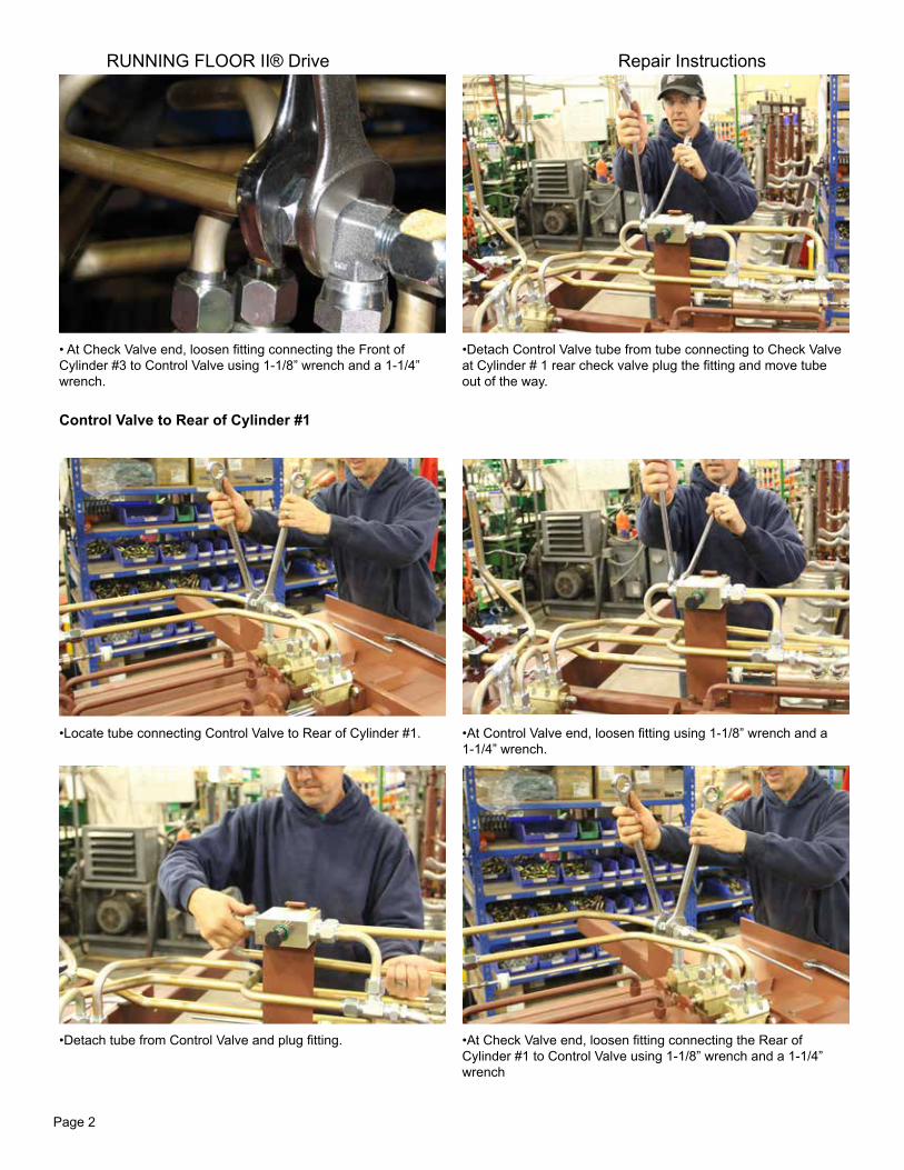
• At Check Valve end, loosen fitting connecting the Front ofCylinder #3 to Control Valve using 1-1/8” wrench and a 1-1/4”wrench.
•Detach Control Valve tube from tube connecting to Check Valveat Cylinder # 1 rear check valve plug the fitting and move tubeout of the way.
Control Valve to Rear of Cylinder #1
•Locate tube connecting Control Valve to Rear of Cylinder #1. •At Control Valve end, loosen fitting using 1-1/8” wrench and a 1-1/4” wrench.
•Detach tube from Control Valve and plug fitting. •At Check Valve end, loosen fitting connecting the Rear of Cylinder #1 to Control Valve using 1-1/8” wrench and a 1-1/4” wrench
Page 3
RUNNING FLOOR II® Drive Repair Instructions
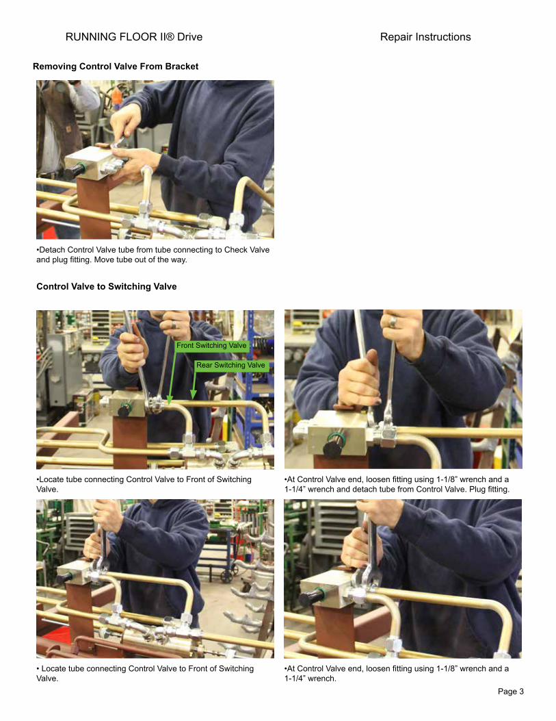
•Detach Control Valve tube from tube connecting to Check Valve and plug fitting. Move tube out of the way.
Control Valve to Switching Valve
•Locate tube connecting Control Valve to Front of Switching Valve.
•At Control Valve end, loosen fitting using 1-1/8” wrench and a 1-1/4” wrench and detach tube from Control Valve. Plug fitting.
• Locate tube connecting Control Valve to Front of Switching Valve.
•At Control Valve end, loosen fitting using 1-1/8” wrench and a 1-1/4” wrench.
Removing Control Valve From Bracket
Front Switching Valve
Rear Switching Valve
Page 4
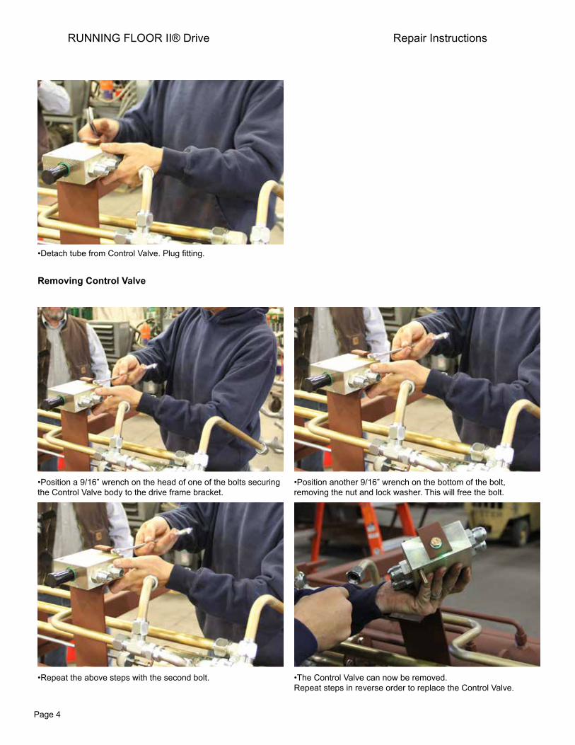
•Detach tube from Control Valve. Plug fitting.
Removing Control Valve
•Position a 9/16” wrench on the head of one of the bolts securing the Control Valve body to the drive frame bracket.
•Position another 9/16” wrench on the bottom of the bolt, removing the nut and lock washer. This will free the bolt.
•Repeat the above steps with the second bolt. •The Control Valve can now be removed.Repeat steps in reverse order to replace the Control Valve.
RUNNING FLOOR II® Drive Repair Instructions
Page 5
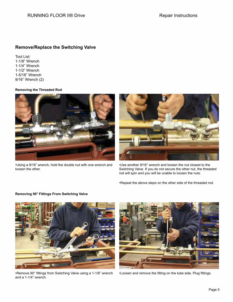
Remove/Replace the Switching Valve
Tool List:1-1/8” Wrench1-1/4” Wrench1-1/2” Wrench1-5/16” Wrench9/16” Wrench (2)
Removing the Threaded Rod
•Using a 9/16” wrench, hold the double nut with one wrench and loosen the other.
•Use another 9/16” wrench and loosen the nut closest to the Switching Valve. If you do not secure the other nut, the threaded rod will spin and you will be unable to loosen the nuts.
•Repeat the above steps on the other side of the threaded rod.
Removing 90° Fittings From Switching Valve
•Remove 90° fittings from Switching Valve using a 1-1/8” wrench and a 1-1/4” wrench.
•Loosen and remove the fitting on the tube side. Plug fittings.
RUNNING FLOOR II® Drive Repair Instructions

Page 6
•Loosen and remove the fitting on the Switching Valve side.•Repeat the above steps on the remaining fitting.
Remove Return Tube Fitting
•Locate the Switching Valve fitting to the Return Tube. •Use 1-5/16” wrench and a 1-1/2” wrench to remove Return Tube fitting.
RUNNING FLOOR II® Drive Repair Instructions
Page 7
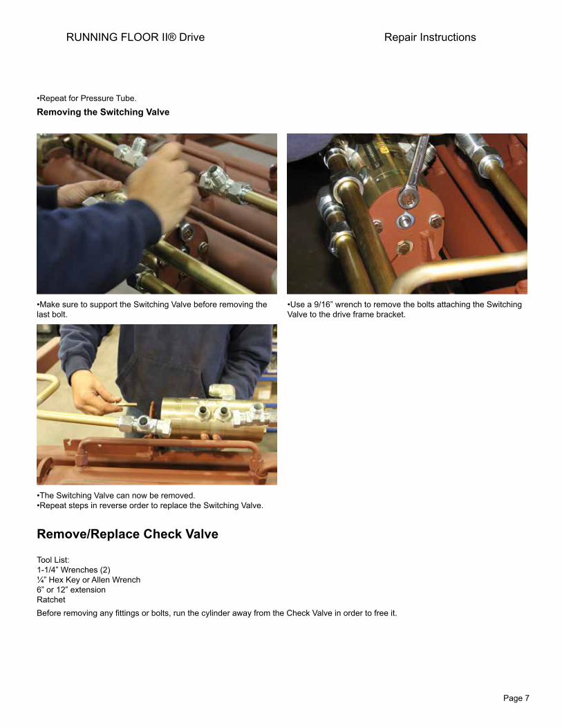
•Repeat for Pressure Tube.
Removing the Switching Valve
•Make sure to support the Switching Valve before removing the last bolt.
•Use a 9/16” wrench to remove the bolts attaching the Switching Valve to the drive frame bracket.
•The Switching Valve can now be removed.•Repeat steps in reverse order to replace the Switching Valve.
Remove/Replace Check Valve
Tool List:1-1/4” Wrenches (2)¼” Hex Key or Allen Wrench6” or 12” extensionRatchetBefore removing any fittings or bolts, run the cylinder away from the Check Valve in order to free it.
RUNNING FLOOR II® Drive Repair Instructions
Page 8
RUNNING FLOOR II® Drive Repair Instructions
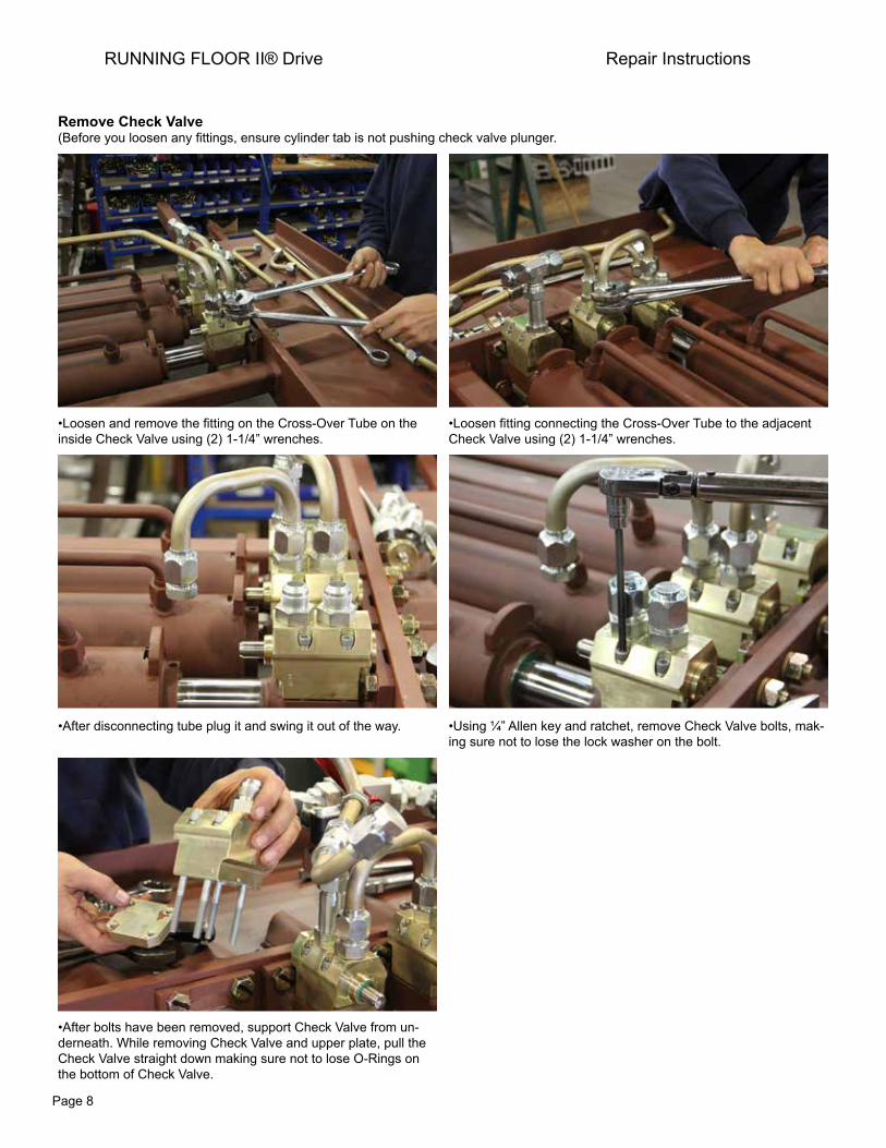
Remove Check Valve (Before you loosen any fittings, ensure cylinder tab is not pushing check valve plunger.
•Loosen and remove the fitting on the Cross-Over Tube on the inside Check Valve using (2) 1-1/4” wrenches.
•Loosen fitting connecting the Cross-Over Tube to the adjacent Check Valve using (2) 1-1/4” wrenches.
•After disconnecting tube plug it and swing it out of the way. •Using ¼” Allen key and ratchet, remove Check Valve bolts, mak-ing sure not to lose the lock washer on the bolt.
•After bolts have been removed, support Check Valve from un-derneath. While removing Check Valve and upper plate, pull the Check Valve straight down making sure not to lose O-Rings on the bottom of Check Valve.

Page 9
Replacing Check Valve
•Before replacing Check Valve, make sure the surface is clean, all grease is removed.
•Make sure Check Valve is properly placed with O-Rings aligned with the ports and lubricate with clean hydraulic oil.
•Place the upper plate over the cylinder rod block making sure that the beveled edges of the plate point to the outside. This is to provide clearance for the cylinder bolts.
•Align bolt holes in the plate with the Check Valve body and hand-tighten the bolts to secure the plate.
•Using ¼” Allen hex key and ratchet, tighten the bolts in the following pattern: (photo showing bolt pattern)
•Torque Check Valve bolts to 20 FT-LBS.
RUNNING FLOOR II® Drive Repair Instructions
Upper Threaded Plate

Page 10
Remove/Replace Cylinder
Tool List:1-1/4” Wrenches (2)¼” Allen Hex Key or Allen Wrench6” or 12” extensionRatchet15/16” Wrench (2)Pry Bar½” Drive Torque Wrench½” Impact Wrench
Remove Cylinder
•Remove Check Valves at each end of the Cylinder. See instructions page 8. Plug all of the fittings and ports.
•Loosen and remove the bolts from the rod end plates at each end of the Cylinder using (2) 15/16” wrenches.
•Using the pry bar, gently move the rod end plate away from the Cylinder mount plate to detach pins.
•Loosen the bolts to one of the lower cross-drive clamp bolts using 15/16” socket with 1/2” drive impact wrench.
RUNNING FLOOR II® Drive Repair Instructions

Page 11
•The Cylinder is heavy. Before loosening the bolts to the second cross-drive clamp, have another person available to support the cylinder.
•The cylinder can now be removed. Always use (2) people to move Cylinder out of frame.
Replace Cylinder
•The Cylinder is heavy. Always use (2) people to move Cylinder into frame.
•Align bolt holes in the rod end plate with the bolt holes in the nut bar. Before torquing cylinder bolts, check all three cylinders for level.
•The nut bar is aluminum so make sure to use anti-seize compound before replacing the steel bolts. Start bolts by hand.
•Hand tighten bolts, then using a torque wrench, torque them to 135 FT-LBS.
RUNNING FLOOR II® Drive Repair Instructions
Page 12
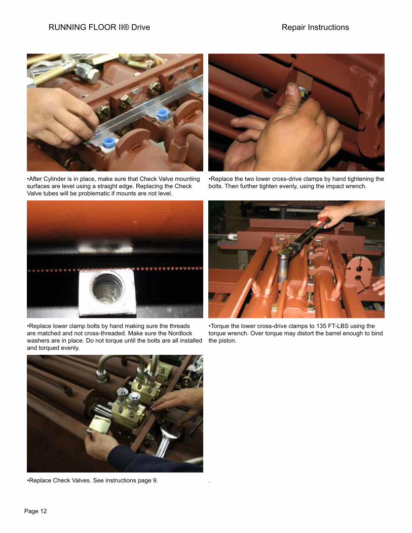
•After Cylinder is in place, make sure that Check Valve mounting surfaces are level using a straight edge. Replacing the Check Valve tubes will be problematic if mounts are not level.
•Replace the two lower cross-drive clamps by hand tightening the bolts. Then further tighten evenly, using the impact wrench.
•Replace lower clamp bolts by hand making sure the threads are matched and not cross-threaded. Make sure the Nordlock washers are in place. Do not torque until the bolts are all installed and torqued evenly.
•Torque the lower cross-drive clamps to 135 FT-LBS using the torque wrench. Over torque may distort the barrel enough to bind the piston.
•Replace Check Valves. See instructions page 9. .
RUNNING FLOOR II® Drive Repair Instructions


![Hq- ® eS Corporate Office: ] @® Floor, Premdeep Building](https://img.dokumen.tips/doc/110x75/6264fdda42488a7507477987/hq-es-corporate-office-floor-premdeep-building-.jpg)

