Embed Size (px)
Citation preview
KameleonMULTI-FUNCTION MODULES
Instruction Manual
SOFTWARE VERSION 4.1.0
071817302APRIL 2005

2 Kameleon Instruction Manual
Contacting Grass Valley
Copyright © Thomson Broadcast and Media Solutions All rights reserved.
Grass Valley Web Site
The www.thomsongrassvalley.com web site offers the following:
Online User Documentation
— Current versions of product catalogs, brochures, data sheets, ordering guides, planning guides, manuals, and release notes in .pdf format can be downloaded.
FAQ Database
— Solutions to problems and troubleshooting efforts can be found by searching our Frequently Asked Questions (FAQ) database.
Software Downloads
— Software updates, drivers, and patches can be down-loaded.
Region Voice Fax Address Web Site
North America (800) 547-8949Support: 530-478-4148
Sales: (530) 478-3347Support: (530) 478-3181
Grass ValleyP.O. Box 599000Nevada City, CA 95959-7900 USA
www.thomsongrassvalley.com
Pacific Operations +852-2585-6688Support: 852-2585-6579
+852-2802-2996
U.K., Asia, Middle East +44 1753 218 777 +44 1753 218 757
France +33 1 45 29 73 00
Germany, Europe +49 6150 104 782 +49 6150 104 223
ContentsPreface. . . . . . . . . . . . . . . . . . . . . . . . . . . . . . . . . . . . . . . . . . . . . . . . . . . . . . . . . . . . . . . . . . . . . 7
About This Manual . . . . . . . . . . . . . . . . . . . . . . . . . . . . . . . . . . . . . . . . . . . . . . . . . . . . . 7
Kameleon Series Multi-function Modules
Introduction . . . . . . . . . . . . . . . . . . . . . . . . . . . . . . . . . . . . . . . . . . . . . . . . . . . . . . . . . . . 9Quickstart Guide . . . . . . . . . . . . . . . . . . . . . . . . . . . . . . . . . . . . . . . . . . . . . . . . . . . . . . 12Installation . . . . . . . . . . . . . . . . . . . . . . . . . . . . . . . . . . . . . . . . . . . . . . . . . . . . . . . . . . . 14
Frame Capacity . . . . . . . . . . . . . . . . . . . . . . . . . . . . . . . . . . . . . . . . . . . . . . . . . . . . . 14Module Placement in the Kameleon Frame. . . . . . . . . . . . . . . . . . . . . . . . . . . . . . 15Cabling . . . . . . . . . . . . . . . . . . . . . . . . . . . . . . . . . . . . . . . . . . . . . . . . . . . . . . . . . . . . 20
KAM-AA-R Configurations . . . . . . . . . . . . . . . . . . . . . . . . . . . . . . . . . . . . . . . . . 21KAM-MIX-R Configurations . . . . . . . . . . . . . . . . . . . . . . . . . . . . . . . . . . . . . . . . 22KAM-AES-R Configurations . . . . . . . . . . . . . . . . . . . . . . . . . . . . . . . . . . . . . . . . 23KAM-AA-AES-UR Configurations . . . . . . . . . . . . . . . . . . . . . . . . . . . . . . . . . . . 25
Power Up . . . . . . . . . . . . . . . . . . . . . . . . . . . . . . . . . . . . . . . . . . . . . . . . . . . . . . . . . . . . 27Operation Indicator LEDs . . . . . . . . . . . . . . . . . . . . . . . . . . . . . . . . . . . . . . . . . . . . 28
Configuration and Adjustments . . . . . . . . . . . . . . . . . . . . . . . . . . . . . . . . . . . . . . . . . 29Configuration Summary. . . . . . . . . . . . . . . . . . . . . . . . . . . . . . . . . . . . . . . . . . . . . . 29Newton Control Panel Configuration . . . . . . . . . . . . . . . . . . . . . . . . . . . . . . . . . . 35Web Browser Interface . . . . . . . . . . . . . . . . . . . . . . . . . . . . . . . . . . . . . . . . . . . . . . . 36Web Page Operations and Functional Elements. . . . . . . . . . . . . . . . . . . . . . . . . . 38
Status and Identification Header . . . . . . . . . . . . . . . . . . . . . . . . . . . . . . . . . . . . . 38Initial Configuration Process Overview. . . . . . . . . . . . . . . . . . . . . . . . . . . . . . . . . 39
KAM-AV and KAM-SD Links and Web Pages . . . . . . . . . . . . . . . . . . . . . . . . . . . . 40Status Web Page. . . . . . . . . . . . . . . . . . . . . . . . . . . . . . . . . . . . . . . . . . . . . . . . . . . . . 41
Color-coded Status Indicators and Links . . . . . . . . . . . . . . . . . . . . . . . . . . . . . . 41Status/Front Module Properties . . . . . . . . . . . . . . . . . . . . . . . . . . . . . . . . . . . . . 41Submodule Properties . . . . . . . . . . . . . . . . . . . . . . . . . . . . . . . . . . . . . . . . . . . . . . 41Warning/Fault Summary . . . . . . . . . . . . . . . . . . . . . . . . . . . . . . . . . . . . . . . . . . . 45
Input/Output Configuration Web Page . . . . . . . . . . . . . . . . . . . . . . . . . . . . . . . . 46I/O Config Page Elements . . . . . . . . . . . . . . . . . . . . . . . . . . . . . . . . . . . . . . . . . . 50
Functional View Web Page . . . . . . . . . . . . . . . . . . . . . . . . . . . . . . . . . . . . . . . . . . . 52Composite In Web Page . . . . . . . . . . . . . . . . . . . . . . . . . . . . . . . . . . . . . . . . . . . . . . 54
Video Input Status . . . . . . . . . . . . . . . . . . . . . . . . . . . . . . . . . . . . . . . . . . . . . . . . . 54Settings for Standard 525/625 . . . . . . . . . . . . . . . . . . . . . . . . . . . . . . . . . . . . . . . 543D Decoder Control . . . . . . . . . . . . . . . . . . . . . . . . . . . . . . . . . . . . . . . . . . . . . . . . 55
VBI Decode Web Page for Composite Input . . . . . . . . . . . . . . . . . . . . . . . . . . . . . 58SDI Input Web Page . . . . . . . . . . . . . . . . . . . . . . . . . . . . . . . . . . . . . . . . . . . . . . . . . 60
Current State . . . . . . . . . . . . . . . . . . . . . . . . . . . . . . . . . . . . . . . . . . . . . . . . . . . . . . 60Reported Errors . . . . . . . . . . . . . . . . . . . . . . . . . . . . . . . . . . . . . . . . . . . . . . . . . . . 60
DEMUX Web Page . . . . . . . . . . . . . . . . . . . . . . . . . . . . . . . . . . . . . . . . . . . . . . . . . . 62Video Input Select Web Page. . . . . . . . . . . . . . . . . . . . . . . . . . . . . . . . . . . . . . . . . . 63
Kameleon Instruction Manual 3
Contents
View Setting . . . . . . . . . . . . . . . . . . . . . . . . . . . . . . . . . . . . . . . . . . . . . . . . . . . . . . 63Video Selection Settings . . . . . . . . . . . . . . . . . . . . . . . . . . . . . . . . . . . . . . . . . . . . 63Output Timing Selection . . . . . . . . . . . . . . . . . . . . . . . . . . . . . . . . . . . . . . . . . . . 64Advanced VBI Configuration . . . . . . . . . . . . . . . . . . . . . . . . . . . . . . . . . . . . . . . 66
Frame Sync Web Page . . . . . . . . . . . . . . . . . . . . . . . . . . . . . . . . . . . . . . . . . . . . . . . 68Timing Adjustment. . . . . . . . . . . . . . . . . . . . . . . . . . . . . . . . . . . . . . . . . . . . . . . . 68Freeze Mode Selection . . . . . . . . . . . . . . . . . . . . . . . . . . . . . . . . . . . . . . . . . . . . . 68
Video Processing Web Page . . . . . . . . . . . . . . . . . . . . . . . . . . . . . . . . . . . . . . . . . . 70Video Processing Controls. . . . . . . . . . . . . . . . . . . . . . . . . . . . . . . . . . . . . . . . . . 70Clipping Controls . . . . . . . . . . . . . . . . . . . . . . . . . . . . . . . . . . . . . . . . . . . . . . . . . 72Advanced View . . . . . . . . . . . . . . . . . . . . . . . . . . . . . . . . . . . . . . . . . . . . . . . . . . . 72Reset To Default . . . . . . . . . . . . . . . . . . . . . . . . . . . . . . . . . . . . . . . . . . . . . . . . . . 72
MUX Web Page . . . . . . . . . . . . . . . . . . . . . . . . . . . . . . . . . . . . . . . . . . . . . . . . . . . . . 74Group Deletion . . . . . . . . . . . . . . . . . . . . . . . . . . . . . . . . . . . . . . . . . . . . . . . . . . . 74Group Replacement . . . . . . . . . . . . . . . . . . . . . . . . . . . . . . . . . . . . . . . . . . . . . . . 77
VBI Encode Web Page for Composite Output . . . . . . . . . . . . . . . . . . . . . . . . . . . 79VBI Data Line Configuration for SDI Output. . . . . . . . . . . . . . . . . . . . . . . . . . . . 81Video Composite Out Web Page . . . . . . . . . . . . . . . . . . . . . . . . . . . . . . . . . . . . . . 83
Signal Setup . . . . . . . . . . . . . . . . . . . . . . . . . . . . . . . . . . . . . . . . . . . . . . . . . . . . . . 84Cross Color Removal . . . . . . . . . . . . . . . . . . . . . . . . . . . . . . . . . . . . . . . . . . . . . . 84Chrominance Removal . . . . . . . . . . . . . . . . . . . . . . . . . . . . . . . . . . . . . . . . . . . . . 84Burst Removal . . . . . . . . . . . . . . . . . . . . . . . . . . . . . . . . . . . . . . . . . . . . . . . . . . . . 84Output Video Adjustments . . . . . . . . . . . . . . . . . . . . . . . . . . . . . . . . . . . . . . . . . 84
SDI Out Web Page . . . . . . . . . . . . . . . . . . . . . . . . . . . . . . . . . . . . . . . . . . . . . . . . . . 86Output Delay Coarse . . . . . . . . . . . . . . . . . . . . . . . . . . . . . . . . . . . . . . . . . . . . . . 86
Analog Audio Inputs Web Page. . . . . . . . . . . . . . . . . . . . . . . . . . . . . . . . . . . . . . . 87Input . . . . . . . . . . . . . . . . . . . . . . . . . . . . . . . . . . . . . . . . . . . . . . . . . . . . . . . . . . . . 88Name. . . . . . . . . . . . . . . . . . . . . . . . . . . . . . . . . . . . . . . . . . . . . . . . . . . . . . . . . . . . 88Maximum Input Level . . . . . . . . . . . . . . . . . . . . . . . . . . . . . . . . . . . . . . . . . . . . . 88Signal Present. . . . . . . . . . . . . . . . . . . . . . . . . . . . . . . . . . . . . . . . . . . . . . . . . . . . . 88Clipping . . . . . . . . . . . . . . . . . . . . . . . . . . . . . . . . . . . . . . . . . . . . . . . . . . . . . . . . . 88
AES Inputs Web Page . . . . . . . . . . . . . . . . . . . . . . . . . . . . . . . . . . . . . . . . . . . . . . . 89Input . . . . . . . . . . . . . . . . . . . . . . . . . . . . . . . . . . . . . . . . . . . . . . . . . . . . . . . . . . . . 89Name. . . . . . . . . . . . . . . . . . . . . . . . . . . . . . . . . . . . . . . . . . . . . . . . . . . . . . . . . . . . 89Signal State . . . . . . . . . . . . . . . . . . . . . . . . . . . . . . . . . . . . . . . . . . . . . . . . . . . . . . . 89Sample Rate . . . . . . . . . . . . . . . . . . . . . . . . . . . . . . . . . . . . . . . . . . . . . . . . . . . . . . 89Mode . . . . . . . . . . . . . . . . . . . . . . . . . . . . . . . . . . . . . . . . . . . . . . . . . . . . . . . . . . . . 90Emphasis . . . . . . . . . . . . . . . . . . . . . . . . . . . . . . . . . . . . . . . . . . . . . . . . . . . . . . . . 90Data . . . . . . . . . . . . . . . . . . . . . . . . . . . . . . . . . . . . . . . . . . . . . . . . . . . . . . . . . . . . . 90AES Errors Detected . . . . . . . . . . . . . . . . . . . . . . . . . . . . . . . . . . . . . . . . . . . . . . . 90
Audio Input Select Web Page . . . . . . . . . . . . . . . . . . . . . . . . . . . . . . . . . . . . . . . . . 91Input Stream Select . . . . . . . . . . . . . . . . . . . . . . . . . . . . . . . . . . . . . . . . . . . . . . . . 92Status. . . . . . . . . . . . . . . . . . . . . . . . . . . . . . . . . . . . . . . . . . . . . . . . . . . . . . . . . . . . 92Sample Rate Convert . . . . . . . . . . . . . . . . . . . . . . . . . . . . . . . . . . . . . . . . . . . . . . 92Loss of Signal Reporting . . . . . . . . . . . . . . . . . . . . . . . . . . . . . . . . . . . . . . . . . . . 92Reporting . . . . . . . . . . . . . . . . . . . . . . . . . . . . . . . . . . . . . . . . . . . . . . . . . . . . . . . . 92AES Errors . . . . . . . . . . . . . . . . . . . . . . . . . . . . . . . . . . . . . . . . . . . . . . . . . . . . . . . 92
Audio Channel Pairing Web Page . . . . . . . . . . . . . . . . . . . . . . . . . . . . . . . . . . . . . 94Audio Sync Web Page . . . . . . . . . . . . . . . . . . . . . . . . . . . . . . . . . . . . . . . . . . . . . . . 95Audio Processing Web Page . . . . . . . . . . . . . . . . . . . . . . . . . . . . . . . . . . . . . . . . . . 96
Audio Gain. . . . . . . . . . . . . . . . . . . . . . . . . . . . . . . . . . . . . . . . . . . . . . . . . . . . . . . 96Output Processing. . . . . . . . . . . . . . . . . . . . . . . . . . . . . . . . . . . . . . . . . . . . . . . . . 96Selecting Output Resolution . . . . . . . . . . . . . . . . . . . . . . . . . . . . . . . . . . . . . . . . 97
Analog Audio Outputs Web Page . . . . . . . . . . . . . . . . . . . . . . . . . . . . . . . . . . . . . 98
4 Kameleon Instruction Manual

Contents
AES Outputs Web Page . . . . . . . . . . . . . . . . . . . . . . . . . . . . . . . . . . . . . . . . . . . . . 100E-MEM Configuration Web Page . . . . . . . . . . . . . . . . . . . . . . . . . . . . . . . . . . . . . 101
File Operations . . . . . . . . . . . . . . . . . . . . . . . . . . . . . . . . . . . . . . . . . . . . . . . . . . . 103Slot Configuration Web Page. . . . . . . . . . . . . . . . . . . . . . . . . . . . . . . . . . . . . . . . . 106
Slot Identification . . . . . . . . . . . . . . . . . . . . . . . . . . . . . . . . . . . . . . . . . . . . . . . . . 106Locate Module . . . . . . . . . . . . . . . . . . . . . . . . . . . . . . . . . . . . . . . . . . . . . . . . . . . 106Slot Memory . . . . . . . . . . . . . . . . . . . . . . . . . . . . . . . . . . . . . . . . . . . . . . . . . . . . . 106Frame Heath Reporting. . . . . . . . . . . . . . . . . . . . . . . . . . . . . . . . . . . . . . . . . . . . 108Hardware Switch Controls . . . . . . . . . . . . . . . . . . . . . . . . . . . . . . . . . . . . . . . . . 108Slot SNMP Trap Reports . . . . . . . . . . . . . . . . . . . . . . . . . . . . . . . . . . . . . . . . . . . 108
Software Update Web Page . . . . . . . . . . . . . . . . . . . . . . . . . . . . . . . . . . . . . . . . . . 109Specifications . . . . . . . . . . . . . . . . . . . . . . . . . . . . . . . . . . . . . . . . . . . . . . . . . . . . . . . . 110Service . . . . . . . . . . . . . . . . . . . . . . . . . . . . . . . . . . . . . . . . . . . . . . . . . . . . . . . . . . . . . . 117
Troubleshooting. . . . . . . . . . . . . . . . . . . . . . . . . . . . . . . . . . . . . . . . . . . . . . . . . . . . 117
Index . . . . . . . . . . . . . . . . . . . . . . . . . . . . . . . . . . . . . . . . . . . . . . . . . . . . . . . . . . . . . . . . . . . . . 119
Kameleon Instruction Manual 5

Contents
6 Kameleon Instruction Manual
Preface
About This ManualThis manual describes the features of a specific 2000 Series module in the Kameleon Media Processing System. As part of this module family, it is subject to Safety and Regulatory Compliance described in the 2000 Series frame and power supply documentation (see the Kameleon 2000 Series Frames Instruction Manual).
Kameleon Instruction Manual 7

Preface
8 Kameleon Instruction Manual
Kameleon Series Multi-function Modules
IntroductionThis manual contains a Quickstart guide supported by references to the complete manual and supporting documents (see Quickstart Guide on page 12). Detailed installation, power up, and configuration information follows the Quickstart Guide.
The Kameleon Series multi-function modules are for use in 2000 Series Kameleon Frames. They are designed for facilities that receive multiple feeds that need considerable audio and video processing. They are partic-ularly well suited for broadcasters and cable facilities that need to manip-ulate or add audio channels to multiple program streams.
Note Kameleon operation requires 2000NET Network Interface Module hardware revision 01A1 or greater with software version 3.2.2 or greater.
Kameleon systems installed in the 2000T3N frame require the 2000FAN fan sled (refer to Figure 7 on page 18).
Kameleon offers processing modules that provide a flexible, compact system of conversion, multiplexing, timing and signal processing functions for standard definition, analog and digital, video and audio.
The Kameleon Modular Series consists of the following:
• Two versions of the front processing module are available,
• SD – SDI video processor with SDI Video I/O and AES/EBU and/or analog audio I/O (with submodules), and
• AV – Composite or SDI video I/O and AES/EBU or analog audio I/O (with submodules).
Kameleon Instruction Manual 9

Introduction
Standard front processing module functions include:
• 3D video decoding (KAM-AV only),
• Up to 8 channels of audio A/D or D/A conversion (with submod-ules),
• Video and audio synchronization,
• 8 channels of audio embedding/de-embedding,
• Audio remapping to specific I/O,
• AES/EBU sample rate conversion,
• Video and audio processing amplifiers,
• Automatic EDH insertion in SD output video,
• Video and audio test signal generators,
• Individual Analog and Digital video timing controls, and
• Powerful VBI (vertical blanking interval) processing.
Four types of rear I/O modules are available:
• KAM-AA-R Analog Audio Rear module,
• KAM-MIX-R Mixed Audio Rear module,
• KAM-AES-R AES Rear module, and
• KAM-AA-AES-UR Rear module.
Two audio conversion submodules that can be installed on the pro-cessing module,
• Four-channel Analog to Digital Conversion Submodule (ADC), and
• Four-channel Digital to Analog Conversion Submodule (DAC).
Note Frame synchronization requires a 2000GEN Genlock Reference Module installed in the 2000 Series Kameleon Frame.
A front and rear module pair are required. The front processing modules provide the signal processing power while the rear module determines the specific I/O connections (refer to Figure 1 on page 11). Separate audio A-to-D and D-to-A converter submodules may be installed in two slots on either version of the processing module.
10 Kameleon Instruction Manual

Introduction
Figure 1. Kameleon Processing and Rear Modules
KAM-AA-R Kameleon Analog Audio Rear Module
Rear I/O Modules
Processing ModuleKAM-SD or KAM-A/V Processor
KAM-AES-R Kameleon AES Rear Module
KAM-AA-AES-UR Kameleon Analog AES (Unbalanced) Rear Module
KAM-MIX-R Kameleon Mixed Audio Rear Module
8173-38
Kameleon Instruction Manual 11

Quickstart Guide
Quickstart Guide1. Install modules in the frame.
Install the rear I/O Module. Install submodules on the front Processing Module if needed (page 18) then install the module in the frame.
2. Connect the frame to the network and navigate the web browser to the frame.
See the 2000NET Instruction Manual for information on configuring your frame IP address and connecting to the network.
3. Navigate to the module you would like to configure and click on the appropriate slot to open configuration links.
4. Navigate to I/O Configuration page to configure AES ports as:
• Inputs or outputs, and
• Balanced or unbalanced (see page 46).
Click on the I/O Config page link on the left side of the page. I/O Config-uration also allows you to assign names for all of the module’s incoming and outgoing signals. Assigning easily recognized names will help later in the configuration process.
5. Connect signal cables.
Configuration will be easier if all of the input signals are connected at this time.
6. Configure the Video Input Select page (see page 63).
Configure the video source and the output timing source. If you have the 2000GEN reference installed in the frame and want the Kameleon to work as a frame sync, set the output timing source to Frame Refer-ence. If not, set the output timing source to Video In.
7. Configure the DEMUX (demultiplex) page (see page 62).
If you are de-multiplexing audio out of the video signal, DEMUX is con-figured next. The audio Demux page is used to extract digital audio groups from incoming SDI video for processing. These audio groups become inputs to the Audio Input Select page.
8. Configure the remaining audio/video pages.
Navigate to the Functional View web page (see page 52 for the KAM-AV or page 53 for the KAM-SD). Starting from the left, use the block diagram links to access and configure the different blocks for the desired operation by clicking on any link in a block.
12 Kameleon Instruction Manual

Quickstart Guide
9. Configure vertical blanking interval (VBI) control.
To support data carried on particular lines, the Kameleon controls certain functions within the vertical blanking interval (VBI) and on some of the active video lines.
We refer to active video lines that are used to carry data as “Data Lines”. Clicking the Advanced (VBI Config) radio button at the top of the Video Input Select page (page 63) displays the controls that allow you to specify which active video lines will be carrying data.
After making selections on this page, use the following pages for con-figuring the VBI/Data Lines:
• VBI Decode – for the composite input (page 58),
• VBI Encode – for the composite output (page 79), and
• VBI SDI – for serial digital output (page 81).
Kameleon Instruction Manual 13

Installation
InstallationTo install the Kameleon modules:
1. Place the passive rear module in a frame slot and tighten the screws on each side of the rear module,
2. Place the processor module in the corresponding front slot, and
3. Cable the signal ports.
All Kameleon modules can be inserted and removed from a 2000 Series Kameleon Frame with power on.
Note Remove the front processing module before removing the rear I/O module.
Audio submodules must be installed or removed with the processing module removed from the frame (processor module powered down).
Frame CapacityKameleon modules can be installed in any 2000 Series frame with a 2000NET interface.
The one rackunit 2000T1DN (with dual 130W power supplies and 2000NET module) or 2000T1DNG (with dual 130W power supplies, 2000NET and 2000GEN modules) frames have no Kameleon module capacity limitations.
The three rackunit 2000T3N (single 240W p/s, 2000FAN, and 2000NET module) and 2000T3NG (single 240W p/s, 2000FAN, 2000NET and 2000GEN modules) frames can be fully populated with Kameleon modules when the 2000FAN fan sled and two power sleds are installed.
Table 1 provides the maximum Kameleon module count for frame types.
Table 1. Power, Cooling, and Module Capacity of 2000 Series Kameleon Frames
Item 2000T3N/DNG
Kameleon FrameCapacity
2000T1DN/NG Kameleon Frame
Capacity
KAM-SD Module set 12 4
KAM-AV Module set 12 4
14 Kameleon Instruction Manual

Installation
Module Placement in the Kameleon FrameThere are twelve slot locations in both the front and rear of a 3 RU frame and four slot locations in a 1 RU frame to accommodate 2000 and Kameleon Series media modules (audio/video signal handling modules).
The Kameleon media modules consist of a two-module set with a pro-cessing module and a passive rear module that can be plugged into any of the frame slot pairs. The rear modules provide the input and output inter-face connectors.
To install a Kameleon module set in a 2000 Series frame:
1. Locate a vacant slot in the rear of the 3 RU frame (Figure 2) or the 2000T1DNG frame (Figure 3).
Figure 2. 2000T3NG Frame, Rear View
Figure 3. 2000T1DNG Frame, Rear View
Media sectionrear slots 1-6
(with three 2000EMI blanks)
Media sectionrear slots 7-12 Network
and referenceinput connections
Power, frameconfiguration,& frame health
connections
8173-27r18173_28
Media sectionrear slots 1-2
(with one 2000EMI blank)
J101
1
2
3
4J102
Media sectionrear slots 3-4
Network
and referenceinput connections
Power connections
Kameleon Instruction Manual 15
Installation
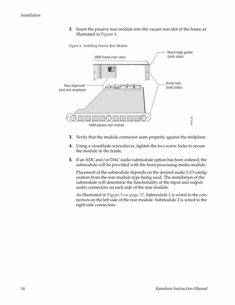
2. Insert the passive rear module into the vacant rear slot of the frame as illustrated in Figure 4.
Figure 4. Installing Passive Rear Module
3. Verify that the module connector seats properly against the midplane.
4. Using a crossblade screwdriver, tighten the two screw locks to secure the module in the frame.
5. If an ADC and/or DAC audio submodule option has been ordered, the submodule will be provided with the front processing media module.
Placement of the submodule depends on the desired audio I/O config-uration from the rear module type being used. The installation of the submodule will determine the functionality of the input and output audio connectors on each side of the rear module.
As illustrated in Figure 5 on page 17, Submodule 1 is wired to the con-nectors on the left side of the rear module. Submodule 2 is wired to the right side connectors.
Rear alignment post and receptacle
Screw lock(both sides)
8173-05r1
2000 frame (rear view)
KAM passive rear module
Board edge guides(both sides)
16 Kameleon Instruction Manual

Installation
Figure 5. Submodule/Rear Connector Relationship
Refer to the rear module cabling information tables for correct place-ment of the submodules to match your requirements as follows:
• KAM-AA-R – designed for eight-channel analog audio I/O (see Table 2 on page 21),
• KAM-MIX-R – designed for mixed I/O of two AES/EBU streams (balanced or unbalanced) and four analog audio channels, (see Table 3 on page 22),
• KAM-AES-R – designed for eight AES/EBU audio, balanced or unbalanced I/O connections (see Table 4 on page 24). No submod-ules are used with this application, and
• KAM-AA-AES-UR – designed for mixed I/O of three dual balanced analog audio inputs or outputs (six channels) and four BNC audio connections for four streams of AES audio inputs, outputs, or two inputs and two outputs (see Table 5 on page 24),
If the submodule(s) needs to be installed, refer to Figure 4 on page 16 for the location of the submodule depending on the application.
8173
_33r
2
Submodule 1
Wired to left side connectors
Wired to right side connectorsSubmodule 2
KAM-AA Rear connectors shown,same relationship for other rear modules
Kameleon Instruction Manual 17

Installation
To install a submodule, line up the connectors on the bottom of the sub-module with the correct submodule position on the top of the media module circuit board (Figure 6). Press firmly to seat the submodule.
After power-up, installation status of the submodule will be reported on the Status web page as described in Status Web Page on page 41.
Figure 6. Kameleon Submodule Installation
6. Locate the corresponding front media slot (1 -12) in the 3 RU frame frame (Figure 7) or front media (slot 1-4) the 1 RU frame (Figure 8 on page 19).
Figure 7. 2000T3NG Kameleon Frame, Front Slots
8173_31r1
Submodule 1
Submodule 2
KAM-ADC/DAC submodule
(2)
(3)
(4)
(5)
(6)
(7)
(8)
(9)
(10)
(11)
(12)
(15)
(13)(1)
8173-04
Network Slot (13) Reference Distribution Slot (15)Main Power Supply Slot (19)
Secondary Power Supply Slot (21)
Front Media Slots (1-12)
Fan SledSlot (20)
18 Kameleon Instruction Manual

Installation
Figure 8. 2000T1DNG Kameleon Frame Front Slots
7. With the component side up, insert the front processing module in the corresponding front slot (see Figure 9).
8. Verify that the module connector seats properly against the midplane and rear module connector.
9. Press firmly on both ejector tabs to seat the module.
Figure 9. Installing Front Media Module
(2)
(3)
(4)
(5)
(6)
(1)
8039-21
Network Slot (5) Power Supply Slot (7)
Front Media Slots (1-4)
Reference Distribution Slot (6)
KAM-SD
Alignment post and receptacle
8173_08
2000 Frame (front view)
Board edge guides
Board edge guides
Kameleon Instruction Manual 19
Installation
CablingAll cabling is done at the corresponding rear module. Four different rear modules are available for various audio and video I/O configurations.
Note The newer KAM-AA-AES-UR model is referred to as an extended rear module because it uses different firmware and has dual analog audio connectors.
All modules accept SDI video in and provide SDI video out. Composite video inputs and outputs are only available with the KAM-AV front module.
Analog audio functions require the use of the audio ADC (analog to digital) and DAC (digital to analog) conversion submodules installed on the front module. Use of the submodules depends on the type of rear module and the audio requirements as described in each rear module cabling section.
Figure 5 on page 17 illustrates the relationship of submodule to rear con-nector for KAM rear modules. AES audio input or output configuration is set by configuring the connector as an input or output on the I/O Config web page (Figure 25 on page 49).
Cabling for each type of rear module is illustrated in the figures listed below:
• KAM-AA-R – see Figure 10 on page 21,
• KAM-MIX-R – see Figure 11 on page 22,
• KAM-AES-R – see Figure 12 on page 23, and
• KAM-AA-AES-UR – see Figure 13 on page 25.
Specific signal names are assigned for each connector using the 2000 GUI using the I/O Config web page (see Configuration and Adjustments on page 29).
20 Kameleon Instruction Manual

Installation
KAM-AA-R ConfigurationsThe KAM-AA-R rear I/O module (Figure 10) accepts either SDI or com-posite video (KAM-AV only). Three video BNC connectors are provided— one each for video in, composite video out (KAM-AV only), and SDI video out. Eight three-terminal audio connectors are provided for analog audio input or output I/O as determined by placement of the audio conversion submodules.
Figure 10. KAM-AA-R Input/Output Connectors
Table 2 provides the various audio input and output I/O configurations based on the positioning of the audio ADC and DAC submodules and the available video outputs. Figure 5 on page 17 illustrates the relationship of submodule to rear connector for KAM rear modules. Submodule installa-tion is shown in Figure 6 on page 18.
Table 2. KAM-AA-R I/O Configurations
Submodule 1 Submodule 2 Video Input Audio Inputs Audio Outputs Video Output
A to D A to D
1 SDI or Composite1 (J11)
1 Only KAM-AV modules support composite video I/O.
8 analog None
1 SDI (J1) and 1 Composite1 (J6)D to A D to A Demux from
SDI input 8 analog
A to D D to A 4 analog 4 analog
8173-09r2
J11 VI, SDI or Composite Video InJ10 AN AUD1, Analog Audio In/Out
J9 AN AUD2, Analog Audio In/OutJ8 AN AUD3, Analog Audio In/Out
J7 AN AUD4, Analog Audio In/Out
J6 CVO, Composite Video Out
J5 AN AUD5, Analog Audio In/OutJ4 AN AUD6, Analog Audio In/Out
J3 AN AUD7, Analog Audio In/OutJ2 AN AUD8, Analog Audio In/Out
J1 SDO, SDI Video Out
Audio Connector
pinout+ – G
J11
SIG
SIG
SDO2900PRM-7
J1J6 J2J3J5 J4J7J8J9J10
CVOAN AUD1 AN AUD2 AN AUD3 AN AUD4 AN AUD5 AN AUD6 AN AUD7 AN AUD8
Kameleon Instruction Manual 21

Installation
KAM-MIX-R ConfigurationsThe KAM-MIX-R rear I/O module (Figure 11) accepts either SDI or com-posite video (KAM-AV only). Five BNC connectors are provided—three for video and two for unbalanced AES/EBU I/O. Six three-terminal audio connectors are provided— four for analog audio I/O and two for analog or balanced AES/EBU I/O.
Figure 11. KAM-MIX-R Input/Output Connectors
Table 3 provides the various audio input and output I/O configurations based on the positioning of the audio ADC and DAC submodules in Posi-tion 1 only and the available video outputs. Figure 5 on page 17 illustrates the relationship of submodule to rear connector for KAM rear modules. Submodule installation is shown in Figure 6 on page 18.
Table 3. KAM-MIX-R I/O Configurations
Submodule 1 Submodule 2 Video Input Audio Inputs Audio Outputs Video Output
A to D None
1 SDI or Composite1
(J11)
1 Only KAM-AV modules support composite video I/O.
4 analog, 2 AES/EBU balanced or unbalanced None
1 SDI (J1) and 1 Composite1 (J6)
D to A None 2 AES/EBU balanced or unbalanced 4 analog
A to D None 4 analog 2 AES/EBU balanced or unbalanced
D to A None None 4 analog, 2 AES/EBU balanced or unbalanced
8173-09r2
J11 VI, SDI or Composite Video InJ10 AN AUD1, Analog Audio In/Out
J9 AN AUD2, Analog Audio In/OutJ8 AN AUD3, Analog Audio In/Out
J7 AN AUD4, Analog Audio In/Out
Audio Connector
pinout+ – G
J11
SIG
SIG
SDO2900PRM-7
J1J6 J2J3J5 J4J7J8J9J10
CVO AES1
AES2AN AUD1 AN AUD2 AN AUD3 AN AUD4 AES 1 AES 2
J6 CVO, Composite Video OutJ5 AES1, Unbalanced AES/EBU Audio In/Out
J4 AES2, Unbalanced AES/EBU Audio In/OutJ3 AES1, Balanced AES/EBU Audio In/Out
J2 AES2, Balanced AES/EBU Audio In/OutJ1 SDO, SDI Video Out
AES connector use:
Paired connectors,must use either balanced or unbalanced
22 Kameleon Instruction Manual

Installation
KAM-AES-R ConfigurationsThe KAM-AES-R rear I/O module accepts either SDI or composite video (KAM-AV only). Seven BNC connectors are provided—three for video and four for unbalanced AES/EBU I/O. Four three-terminal audio connectors are provided for AES/EBU balanced audio I/O. AES/EBU connectors are configured in pairs as shown in Figure 12.
Figure 12. KAM-AES-R Input/Output Connectors
8173-11r1
Audio Connector
pinout+ – G
J11
SIG
SIG
SDO2900PRM-7
J1J6 J2J3J5 J4J7J8J9J10
CVO AES3
AES1
AES2
AES4AES 2AES 1 AES 4AES 3
AES connector use:
Paired connectors,must use either balanced or unbalanced
Paired connectors,must use either balanced or unbalanced
J11 VI, SDI or Composite Video InJ10 AES1, Unbalanced AES/EBU Audio In/Out
J9 AES2, Unbalanced AES/EBU Audio In/OutJ8 AES1, Balanced AES/EBU Audio In/Out
J7 AES2, Balanced AES/EBU Audio In/Out
J6 CVO, Composite Video OutJ5 AES3, Unbalanced AES/EBU Audio In/Out
J4 AES4, Unbalanced AES/EBU Audio In/OutJ3 AES3, Balanced AES/EBU Audio In/Out
J2 AES4, Balanced AES/EBU Audio In/OutJ1 SDO, SDI Video Out
Kameleon Instruction Manual 23
Installation
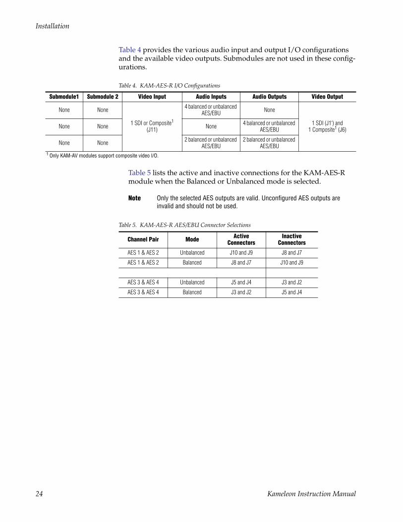
Table 4 provides the various audio input and output I/O configurations and the available video outputs. Submodules are not used in these config-urations.
Table 4. KAM-AES-R I/O Configurations
Submodule1 Submodule 2 Video Input Audio Inputs Audio Outputs Video Output
None None
1 SDI or Composite1 (J11)
1 Only KAM-AV modules support composite video I/O.
Table 5 lists the active and inactive connections for the KAM-AES-R module when the Balanced or Unbalanced mode is selected.
Note Only the selected AES outputs are valid. Unconfigured AES outputs are invalid and should not be used.
4 balanced or unbalanced AES/EBU None
1 SDI (J1‘) and 1 Composite1 (J6) None None None 4 balanced or unbalanced
AES/EBU
None None 2 balanced or unbalanced AES/EBU
2 balanced or unbalanced AES/EBU
Table 5. KAM-AES-R AES/EBU Connector Selections
Channel Pair Mode Active Connectors
Inactive Connectors
AES 1 & AES 2 Unbalanced J10 and J9 J8 and J7
AES 1 & AES 2 Balanced J8 and J7 J10 and J9
AES 3 & AES 4 Unbalanced J5 and J4 J3 and J2
AES 3 & AES 4 Balanced J3 and J2 J5 and J4
24 Kameleon Instruction Manual

Installation
KAM-AA-AES-UR ConfigurationsThe KAM-AA-AES-UR rear I/O module (Figure 13) accepts either SDI or composite video (KAM-AV only). Three BNC connectors are provided for video—one video input, one composite output (KAM-AV only), and one SDI video output. Three dual terminal audio connectors are provided for analog audio input or output I/O. Four BNCs are provided for unbalanced input or output AES I/O.
Figure 13. KAM-AA-AES-UR Input/Output Connectors
Analog Audio Analog Audio
J10
V1
SIG
SDOAES AES AES AESKAM-AAAES-UR
J1J2J3J4J5J6J7J8J9
CVO
Analog Audio:All Inputs or All Outputs
Unbalanced AES: (Four Streams)All Inputs, All Outputs or 2 Inputs/2 Outputs
Connector Use:
Analog Audio:All Inputs or All Outputs
Dual Audio Connector
pinout+ – G
8173-36
J10 VI, SDI or Composite Video In
J7 CVO, Composite Video Out
J9 Analog Audio, In or Out
J6 Analog Audio, In or Out
J8 Analog Audio, In or Out
J1 SDO, SDI Video Out
J5, Unbalanced AES, In or OutJ4, Unbalanced AES, In or Out
J3, Unbalanced AES, In or OutJ2, Unbalanced AES, In or Out
Kameleon Instruction Manual 25
Installation
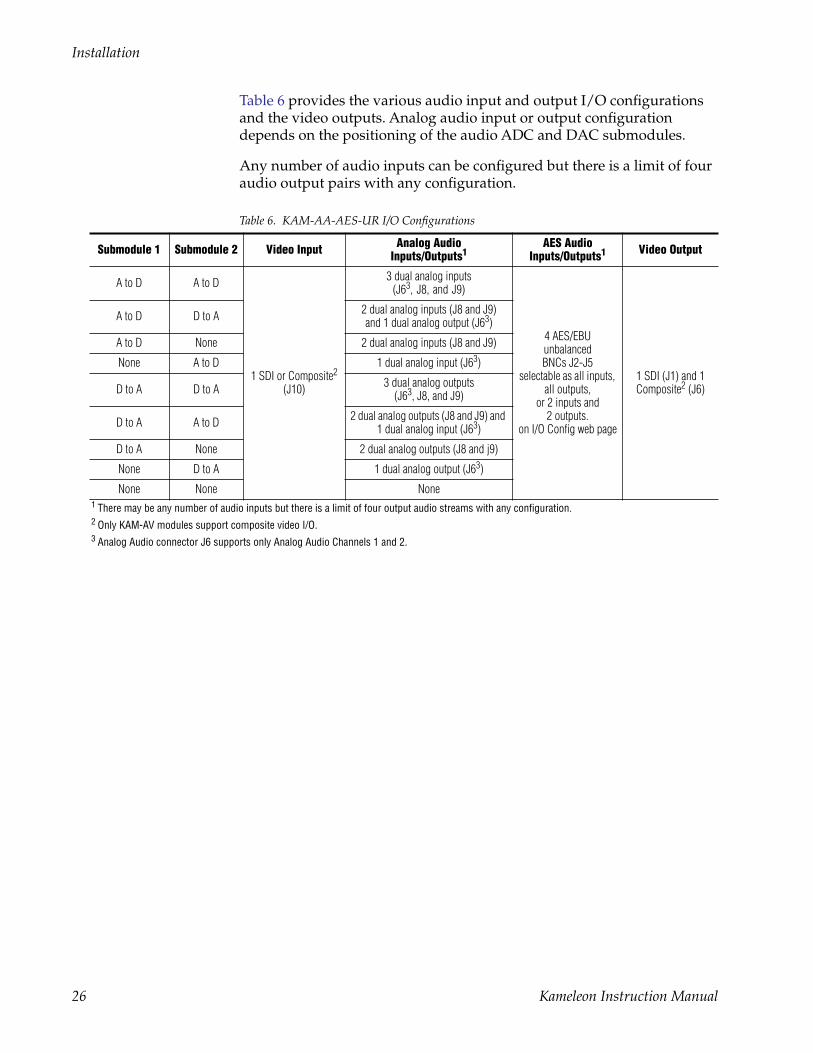
Table 6 provides the various audio input and output I/O configurations and the video outputs. Analog audio input or output configuration depends on the positioning of the audio ADC and DAC submodules.
Any number of audio inputs can be configured but there is a limit of four audio output pairs with any configuration.
Table 6. KAM-AA-AES-UR I/O Configurations
Submodule 1 Submodule 2 Video Input Analog Audio Inputs/Outputs1
1 There may be any number of audio inputs but there is a limit of four output audio streams with any configuration.
AES AudioInputs/Outputs1 Video Output
A to D A to D
1 SDI or Composite2
(J10)
2 Only KAM-AV modules support composite video I/O.
3 dual analog inputs(J63, J8, and J9)
3 Analog Audio connector J6 supports only Analog Audio Channels 1 and 2.
4 AES/EBU unbalanced BNCs J2-J5
selectable as all inputs, all outputs,
or 2 inputs and 2 outputs.
on I/O Config web page
1 SDI (J1) and 1 Composite2 (J6)
A to D D to A 2 dual analog inputs (J8 and J9)and 1 dual analog output (J63)
A to D None 2 dual analog inputs (J8 and J9)
None A to D 1 dual analog input (J63)
D to A D to A 3 dual analog outputs(J63, J8, and J9)
D to A A to D 2 dual analog outputs (J8 and J9) and 1 dual analog input (J63)
D to A None 2 dual analog outputs (J8 and j9)
None D to A 1 dual analog output (J63)
None None None
26 Kameleon Instruction Manual
Power Up
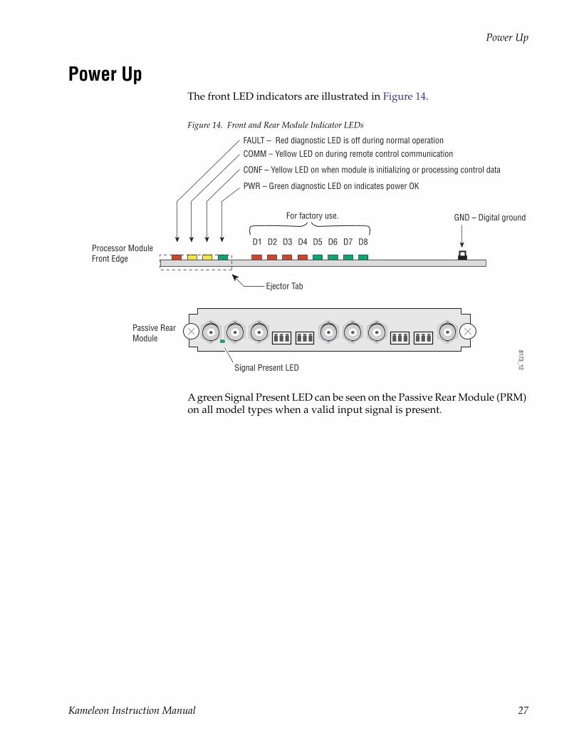
Power UpThe front LED indicators are illustrated in Figure 14.
Figure 14. Front and Rear Module Indicator LEDs
A green Signal Present LED can be seen on the Passive Rear Module (PRM) on all model types when a valid input signal is present.
D1 D2 D3 D4 D5 D6 D7 D8
PWR – Green diagnostic LED on indicates power OK
For factory use.
FAULT – Red diagnostic LED is off during normal operation
Ejector Tab
Processor ModuleFront Edge
Passive RearModule
COMM – Yellow LED on during remote control communication
CONF – Yellow LED on when module is initializing or processing control data
GND – Digital ground
8173_12Signal Present LED
Kameleon Instruction Manual 27

Power Up
Operation Indicator LEDsTable 7 provides a complete list of possible operating conditions and the resulting indicator status.
A red FAULT LED indicates an error situation. Table 7 describes signal output and LED indications for the various input/reference combinations and user settings.
Note The yellow COMM and CONF LEDs are used for the module location function that is enabled using the 2000NET GUI. The module location function causes these LEDs to repeatedly flash concurrently three times followed by an off state of 900 ms duration (see Slot Configuration Web Page on page 106).
Table 7. Indicator LEDs and Conditions Indicated
LED Indication Condition
Fault(red)
Off Normal operation
On continuously Module has detected internal fault
Long flash One of the inputs is missing or is wrong standard
Short flash Errors present in SDI and/or AES/EBU input
COMM(yellow)
Off No activity on frame communication bus
Three flash/off pattern Module Location command received from a remote control system
Short flash Activity present on the frame communication bus
CONF (yellow)
Off Module is in normal operating mode
Three flash/off pattern Module Location command received from a remote control system
On continuously Module is initializing, changing operating modes or updating firmware. (When solid on along with Fault LED on, board has failed to load data.)
PWR (green)
Off No power to module or module’s DC/DC converter failed
On continuously Normal operation, module is powered
28 Kameleon Instruction Manual
Configuration and Adjustments
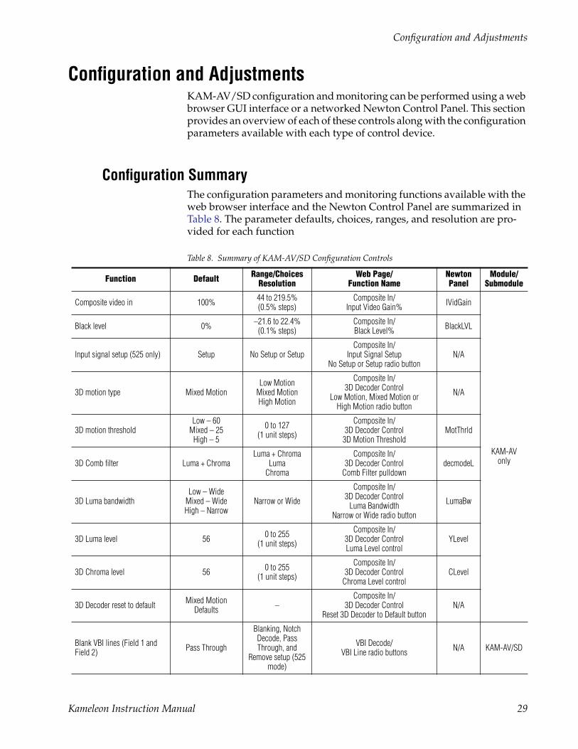
Configuration and AdjustmentsKAM-AV/SD configuration and monitoring can be performed using a web browser GUI interface or a networked Newton Control Panel. This section provides an overview of each of these controls along with the configuration parameters available with each type of control device.
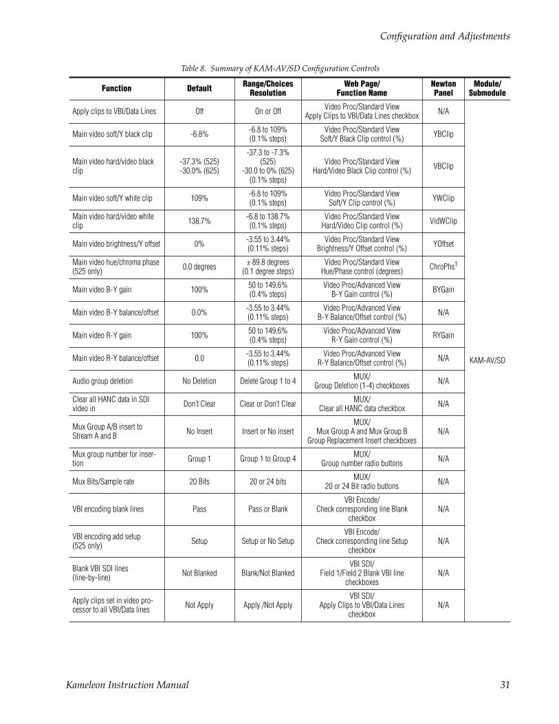
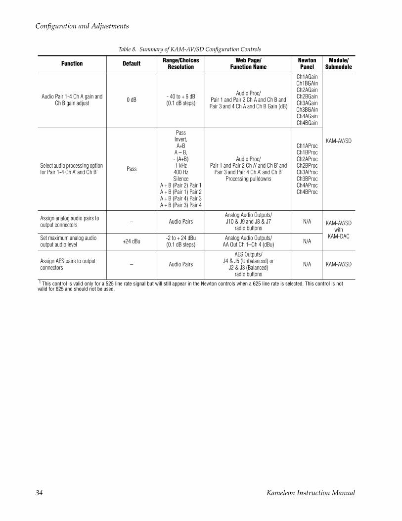
Configuration SummaryThe configuration parameters and monitoring functions available with the web browser interface and the Newton Control Panel are summarized in Table 8. The parameter defaults, choices, ranges, and resolution are pro-vided for each function
Table 8. Summary of KAM-AV/SD Configuration Controls
Function Default Range/ChoicesResolution
Web Page/Function Name
NewtonPanel
Module/Submodule
Composite video in 100% 44 to 219.5%(0.5% steps)
Composite In/Input Video Gain% IVidGain
KAM-AVonly
Black level 0% –21.6 to 22.4%(0.1% steps)
Composite In/Black Level% BlackLVL
Input signal setup (525 only) Setup No Setup or SetupComposite In/
Input Signal SetupNo Setup or Setup radio button
N/A
3D motion type Mixed MotionLow Motion
Mixed MotionHigh Motion
Composite In/3D Decoder Control
Low Motion, Mixed Motion or High Motion radio button
N/A
3D motion thresholdLow – 60
Mixed – 25High – 5
0 to 127(1 unit steps)
Composite In/3D Decoder Control
3D Motion ThresholdMotThrld
3D Comb filter Luma + ChromaLuma + Chroma
LumaChroma
Composite In/3D Decoder Control
Comb Filter pulldowndecmodeL
3D Luma bandwidthLow – Wide
Mixed – WideHigh – Narrow
Narrow or Wide
Composite In/3D Decoder Control
Luma BandwidthNarrow or Wide radio button
LumaBw
3D Luma level 56 0 to 255(1 unit steps)
Composite In/3D Decoder ControlLuma Level control
YLevel
3D Chroma level 56 0 to 255(1 unit steps)
Composite In/3D Decoder Control
Chroma Level control CLevel
3D Decoder reset to default Mixed MotionDefaults –
Composite In/3D Decoder Control
Reset 3D Decoder to Default buttonN/A
Blank VBI lines (Field 1 and Field 2) Pass Through
Blanking, Notch Decode, Pass Through, and
Remove setup (525 mode)
VBI Decode/VBI Line radio buttons N/A KAM-AV/SD
Kameleon Instruction Manual 29

Configuration and Adjustments
SDI In web page view selection Summary Summary or Detail SDI In/Summary or Detail radio button N/A
KAM-AV/SD
Set error reporting for SDI input video Enabled Enabled or Disabled SDI In/Detail View/
Check or uncheck error checkboxes N/A
Demultiplex embedded audio from SDI in No Extraction No Extraction,
Video In.G1 to G4DEMUX/
Str1 & Str2 column radio button N/A
Input status loss of signal report Enable Enable or Disable
Video Input Select/Input Status Report Loss of Signal
checkboxN/A
Select video line rate Auto 525, 625, or Auto Video Input Select/Video Line Rate radio button N/A
Frame reference loss of signal report Enable Enable or Disable
Video Input Select/Frame Reference Loss of Signal
checkboxN/A
Warning on SDI input errors Warn Warn or No WarningVideo Input Select/SDI Input Errors/
Warn SDI Errors checkboxN/A
Select output timing source Video InVideo In or
Internal Frame Ref-erence
Video Input Select/Output Timing Selection radio buttons N/A
Define VBI data lines None
525: None, 21/284, 22/285, 23/286 or
24/287625: None, 24/337, 25/338, 26/339 or 27/340 or 28/341
Video Input Select/Advanced (VBI Config) radio buttonVBI/Data Lines Last Data Line radio
button
N/A
Main video horizontal timing adjustment 0
525: 0 to 857.5 pix-els
625: 0 to 863.5(0.5 pixel steps)
Frame Sync/HTiming control (pixels) HTiming
Main video vertical timing adjustment 0
525: 0 to 524 lines625: 0 to 624 lines
(1 line steps)
Frame Sync/VTiming control (Lines) VTiming
Freeze mode selection (Video In timing source) None
None, Field 1, Field 2,
or Frame
Frame Sync/Freeze Mode Selection radio buttons N/A
Freeze mode selection (Inter-nal timing source) None
None, AutoBlack,AutoFreeze, Field 1,
Field 2, or Frame
Frame Sync/Freeze Mode Selection radio buttons N/A
Enable video processing Enable Disable, Enable, or Color Bars
Video Proc/Video Processing radio buttons N/A
Video gain lock Off On or Off Video Proc/Video Gain Lock radio button N/A
Main video contrast/Y gain 100% 50 to 149.6%(0.4% steps)
Video Proc/Standard ViewY Gain control (%) YGain
Main video chroma gain 100% 50 to 149.6%(0.4% steps)
Video Proc/Standard ViewChroma Gain control (%) ChroGain
Enable Clip controls Disable Enable or Disable Video Proc/Standard ViewClip Settings radio button N/A
Table 8. Summary of KAM-AV/SD Configuration Controls
Function Default Range/ChoicesResolution
Web Page/Function Name
NewtonPanel
Module/Submodule
30 Kameleon Instruction Manual
Configuration and Adjustments
Apply clips to VBI/Data Lines Off On or Off Video Proc/Standard ViewApply Clips to VBI/Data Lines checkbox N/A
KAM-AV/SD
Main video soft/Y black clip -6.8% -6.8 to 109%(0.1% steps)
Video Proc/Standard ViewSoft/Y Black Clip control (%) YBClip
Main video hard/video black clip
-37.3% (525)-30.0% (625)
-37.3 to -7.3% (525)
-30.0 to 0% (625)(0.1% steps)
Video Proc/Standard ViewHard/Video Black Clip control (%) VBClip
Main video soft/Y white clip 109% -6.8 to 109%(0.1% steps)
Video Proc/Standard ViewSoft/Y Clip control (%) YWClip
Main video hard/video white clip 138.7% -6.8 to 138.7%
(0.1% steps)Video Proc/Standard View
Hard/Video Clip control (%) VidWClip
Main video brightness/Y offset 0% -3.55 to 3.44%(0.11% steps)
Video Proc/Standard ViewBrightness/Y Offset control (%) YOffset
Main video hue/chroma phase(525 only) 0.0 degrees ± 89.8 degrees
(0.1 degree steps)Video Proc/Standard View
Hue/Phase control (degrees) ChroPhs1
Main video B-Y gain 100% 50 to 149.6%(0.4% steps)
Video Proc/Advanced ViewB-Y Gain control (%) BYGain
Main video B-Y balance/offset 0.0% -3.55 to 3.44%(0.11% steps)
Video Proc/Advanced ViewB-Y Balance/Offset control (%) N/A
Main video R-Y gain 100% 50 to 149.6%(0.4% steps)
Video Proc/Advanced ViewR-Y Gain control (%) RYGain
Main video R-Y balance/offset 0.0 -3.55 to 3.44%(0.11% steps)
Video Proc/Advanced ViewR-Y Balance/Offset control (%) N/A
Audio group deletion No Deletion Delete Group 1 to 4 MUX/Group Deletion (1-4) checkboxes N/A
Clear all HANC data in SDI video in Don’t Clear Clear or Don’t Clear MUX/
Clear all HANC data checkbox N/A
Mux Group A/B insert to Stream A and B No Insert Insert or No insert
MUX/Mux Group A and Mux Group B
Group Replacement Insert checkboxesN/A
Mux group number for inser-tion Group 1 Group 1 to Group 4 MUX/
Group number radio buttons N/A
Mux Bits/Sample rate 20 Bits 20 or 24 bits MUX/20 or 24 Bit radio buttons N/A
VBI encoding blank lines Pass Pass or BlankVBI Encode/
Check corresponding line Blank checkbox
N/A
VBI encoding add setup (525 only) Setup Setup or No Setup
VBI Encode/Check corresponding line Setup
checkboxN/A
Blank VBI SDI lines (line-by-line) Not Blanked Blank/Not Blanked
VBI SDI/Field 1/Field 2 Blank VBI line
checkboxesN/A
Apply clips set in video pro-cessor to all VBI/Data lines Not Apply Apply /Not Apply
VBI SDI/Apply Clips to VBI/Data Lines
checkboxN/A
Table 8. Summary of KAM-AV/SD Configuration Controls
Function Default Range/ChoicesResolution
Web Page/Function Name
NewtonPanel
Module/Submodule
Kameleon Instruction Manual 31

Configuration and Adjustments
Add setup to composite output Setup Setup or No Setup Composite Out/Setup or No Setup radio button N/A
KAM-AV only
Cross Color Removal (composite out) Disable Enable or Disable
Composite Out/Cross Color Removal
Disable or Enable radio buttonN/A
Chrominance Signal (composite out) Enable Enable or Disable
Composite Out/Chrominance Signal
Disable or Enable radio buttonN/A
Burst Signal (composite out) Enable Enable or DisableComposite Out/
Burst SignalDisable or Enable radio button
N/A
Adjust Coarse Video Delay(composite out) 0 pixels 0 to 4095.5 pixels
(0.5 pixel steps)Composite Out/
Delay Coarse (pixels) Coarse Dly
Adjust Fine Video Delay (composite out) 0 pixels 0 to 100%
(1% steps)Composite Out/Delay Fine (%) Fine Dly
Composite Out video gain 100% 61 to 138.5%(0.5% steps)
Composite Out/Output Video Gain (%) OVidGain
Output Video Adjustment Calibrated Calibrated or User adjustable
Composite Out/Calibrated or User Adjustable
radio buttonN/A
Adjust Composite Out luma gain 100% 50 to 150%
(1% steps)Composite Out/User Adjustable view
Luma Gain (%) N/A
Adjust Composite Out black level 0.0% -7.5 to + 15%
(0.1% steps)Composite Out/User Adjustable view
Black Level (%) N/A
Adjust Composite Out chroma gain 0.0% 50 to 150%
(1% steps)Composite Out/User Adjustable view
Chroma Gain (%) N/A
Adjust Composite Out hue (525 only) 0.0% ± 22.5 degrees
(0.5 degree steps)Composite Out/User Adjustable view
Hue (deg) N/A
SDI output delay adjustment 0 pixels 0.0 to 4095.5 pixels(0.5 pixels)
SDI OutOutput Delay Coarse (pixels) N/A KAM-AV/SD
Set analog audio input levels (Ch 1–Ch 4) 24.0 dBu -2 to 28 dBu
(0.1 dBu steps)Analog Audio Inputs
Max Input Level (dBu) Ch1-4 N/AKAM-AV/SD
with KAM-ADC
Audio input select Silence
Silence,AES In 1 Unbal
Ch1&2AES In 2 Unbal
Ch1&2AES In 1 Bal Ch1&2AES In 2 Bal Ch1&2
G1.S1.Ch1&Ch2G1.S2.Ch1&Ch2G2.S1.Ch1&Ch2G2.S2.Ch1&Ch2G3.S1.Ch1&Ch2G3.S2.Ch1&Ch2G4.S1.Ch1&Ch2G4.S2.Ch1&Ch2AA In Ch1&Ch2AA In Ch3&Ch4
Audio Input Select/Input Stream Select
Input Stream1-4 radio buttonN/A
Available audio inputs depend on
rear module types and embedded
audio present in SDI input
Table 8. Summary of KAM-AV/SD Configuration Controls
Function Default Range/ChoicesResolution
Web Page/Function Name
NewtonPanel
Module/Submodule
32 Kameleon Instruction Manual

Configuration and Adjustments
AES input sample rate Disable Enable or Disable Audio Input Select/Sample Rate Convert disable checkbox N/A
KAM-AV/SD
AES input loss of signal report Enable Enable or Disable Audio Input Select/Loss of Signal Report checkbox N/A
AES input AES error warning Enable Enable or Disable Audio Input Select/AES Error Warn checkbox N/A
Audio channel pair swap – –
Audio Channel Pairing/Pair 1 and 2 Ch A and Ch B and
Pair 3 and 4 Ch A and Ch B radio buttons
Pair1SwpPair2SwpPair3SwpPair4Swp
Define audio Pair 1-4 Ch A and Ch B audio streams
Pair1ChA = Str1.Ch1Pair1ChB = Str1.Ch2Pair2ChA = Str2.Ch1Pair2Ch B= Str2.Ch2Pair3ChA = Str3.Ch1Pair3ChB = Str3.Ch2Pair4ChA = Str4.Ch1Pair4ChB= Str4.Ch2
Str1.Ch1Str1.Ch2Str2.Ch1Str2.Ch2Str3.Ch1Str3.Ch2Str4.Ch1Str4.Ch2
Audio Channel Pairing/Pair 1 and 2 Ch A and Ch B
radio buttons
Pair1ChAPair1ChBPair2ChAPair2ChBPair3ChAPair3ChBPair4ChAPair4ChB
Enable auto tracking for Pair 1-4 Ch A and Ch B Off On or Off
Audio Sync/Pair 1 and Pair 2 Ch A and Ch BEnable Auto Track On checkbox
N/A
Lock Pair 1-4 Ch A and Ch B delay adjustments Unlocked Lock or Unlocked
Audio Sync/Pair 1 and Pair 2 Ch A and Ch B and
Pair 3 and 4 Ch A and Ch BChannel Lock Locked checkbox
N/A
Audio Pair 1 Ch A delay adjustAudio Pair 1 Ch B delay adjustAudio Pair 2 Ch A delay adjustAudio Pair 2 Ch B delay adjustAudio Pair 3 Ch A delay adjustAudio Pair 3 Ch B delay adjustAudio Pair 4 Ch A delay adjustAudio Pair 4 Ch B delay adjust
0 ms 0 to 5180 ms(20 ms steps)
Audio Sync/Pair 1 and Pair 2 Ch A and Ch B and
Pair 3 and 4 Ch A and Ch BDelay controls (ms)
Ch1ADlyCh1BDlyCh2ADlyCh2BDlyCh3ADlyCh3BDlyCh4ADlyCh4BDly
Lock Pair 1-4 Ch A and Ch B gain adjustments Unlocked Lock or Unlocked
Audio Proc/Pair 1 and Pair 2 Ch A and Ch B and
Pair 3 and 4 Ch A and Ch BLocked checkbox
N/A
Table 8. Summary of KAM-AV/SD Configuration Controls
Function Default Range/ChoicesResolution
Web Page/Function Name
NewtonPanel
Module/Submodule
Kameleon Instruction Manual 33
Configuration and Adjustments
Audio Pair 1-4 Ch A gain and Ch B gain adjust 0 dB - 40 to + 6 dB
(0.1 dB steps)
Audio Proc/Pair 1 and Pair 2 Ch A and Ch B and
Pair 3 and 4 Ch A and Ch B Gain (dB)
Ch1AGainCh1BGAinCh2AGainCh2BGainCh3AGainCh3BGAinCh4AGainCh4BGain
KAM-AV/SD
Select audio processing option for Pair 1-4 Ch A’ and Ch B’ Pass
PassInvert,A+B
A – B,- (A+B)1 kHz
400 HzSilence
A + B (Pair 2) Pair 1A + B (Pair 1) Pair 2A + B (Pair 4) Pair 3A + B (Pair 3) Pair 4
Audio Proc/Pair 1 and Pair 2 Ch A’ and Ch B’ and
Pair 3 and Pair 4 Ch A’ and Ch B’Processing pulldowns
Ch1AProcCh1BProcCh2AProcCh2BProcCh3AProcCh3BProcCh4AProcCh4BProc
Assign analog audio pairs to output connectors – Audio Pairs
Analog Audio Outputs/J10 & J9 and J8 & J7
radio buttonsN/A KAM-AV/SD
with KAM-DACSet maximum analog audio
output audio level +24 dBu -2 to + 24 dBu(0.1 dB steps)
Analog Audio Outputs/AA Out Ch 1–Ch 4 (dBu) N/A
Assign AES pairs to output connectors – Audio Pairs
AES Outputs/J4 & J5 (Unbalanced) or
J2 & J3 (Balanced)radio buttons
N/A KAM-AV/SD
1 This control is valid only for a 525 line rate signal but will still appear in the Newton controls when a 625 line rate is selected. This control is notvalid for 625 and should not be used.
Table 8. Summary of KAM-AV/SD Configuration Controls
Function Default Range/ChoicesResolution
Web Page/Function Name
NewtonPanel
Module/Submodule
34 Kameleon Instruction Manual
Configuration and Adjustments
Newton Control Panel ConfigurationA Newton Control Panel (hard or soft version) can be interfaced to the Kameleon 2000 Series frame over the local network. Control panel access offers the following considerations for module configuration and moni-toring:
• Ability to separate system level tasks from operation ones, minimizing the potential for on-air mistakes.
• Ability to group modular products—regardless of their physical loca-tions—into logical groups (channels) that you can easily manipulate with user-configured knobs.
• Update software for applicable modules and assign frame and panel IP addresses with the NetConfig Networking application.
• Recommended for real-time control of module configuration parame-ters, providing the fastest response time.
Note Not all module functions are available with the control panel, such as E-MEM and factory default recalls. The available control panel controls for the module are listed in Table 8 on page 29.
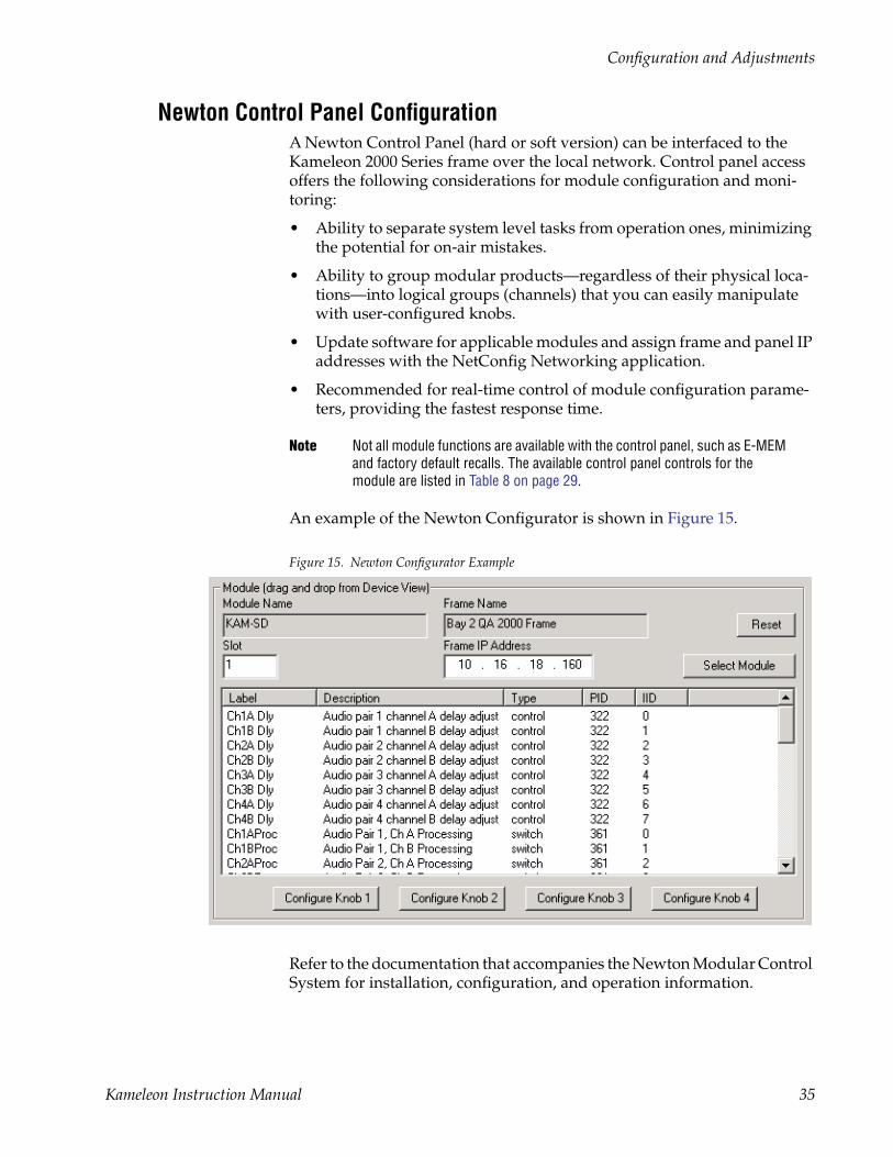
An example of the Newton Configurator is shown in Figure 15.
Figure 15. Newton Configurator Example
Refer to the documentation that accompanies the Newton Modular Control System for installation, configuration, and operation information.
Kameleon Instruction Manual 35
Configuration and Adjustments
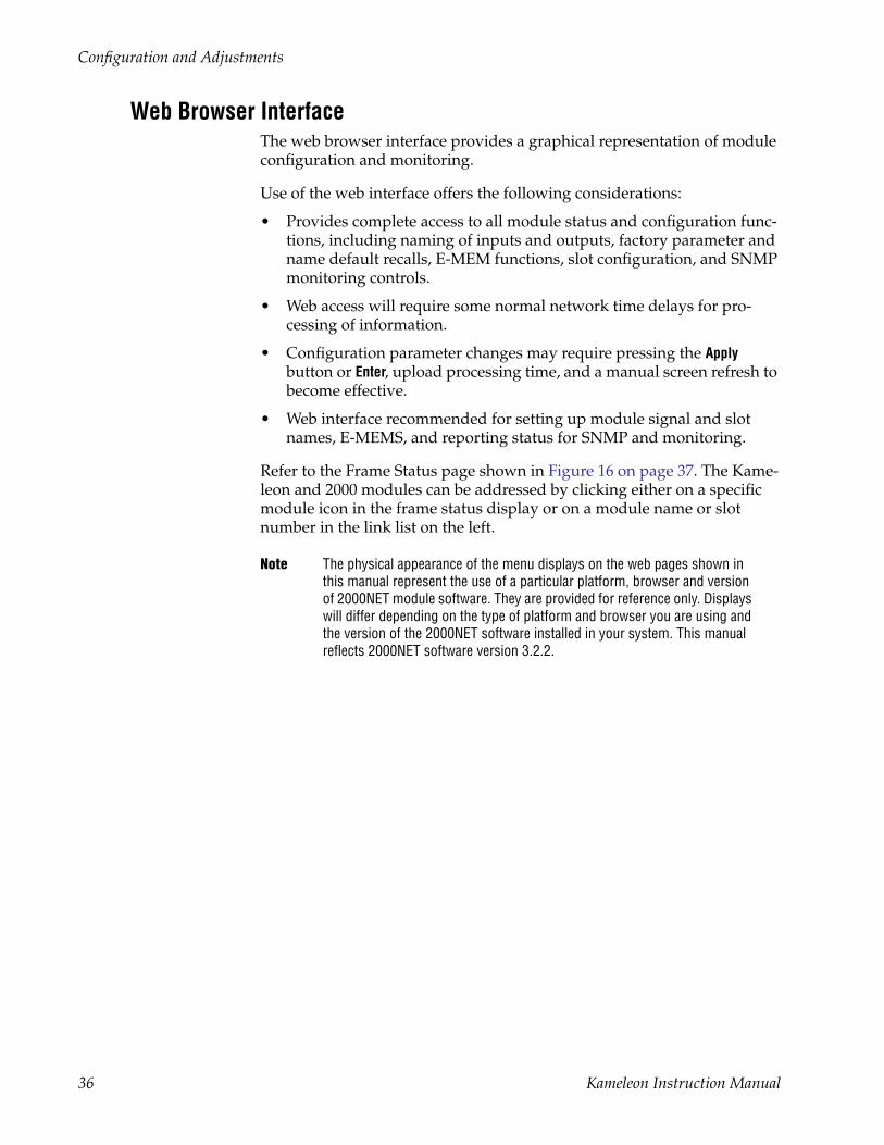
Web Browser InterfaceThe web browser interface provides a graphical representation of module configuration and monitoring.
Use of the web interface offers the following considerations:
• Provides complete access to all module status and configuration func-tions, including naming of inputs and outputs, factory parameter and name default recalls, E-MEM functions, slot configuration, and SNMP monitoring controls.
• Web access will require some normal network time delays for pro-cessing of information.
• Configuration parameter changes may require pressing the Apply button or Enter, upload processing time, and a manual screen refresh to become effective.
• Web interface recommended for setting up module signal and slot names, E-MEMS, and reporting status for SNMP and monitoring.
Refer to the Frame Status page shown in Figure 16 on page 37. The Kame-leon and 2000 modules can be addressed by clicking either on a specific module icon in the frame status display or on a module name or slot number in the link list on the left.
Note The physical appearance of the menu displays on the web pages shown in this manual represent the use of a particular platform, browser and version of 2000NET module software. They are provided for reference only. Displays will differ depending on the type of platform and browser you are using and the version of the 2000NET software installed in your system. This manual reflects 2000NET software version 3.2.2.
36 Kameleon Instruction Manual
Configuration and Adjustments
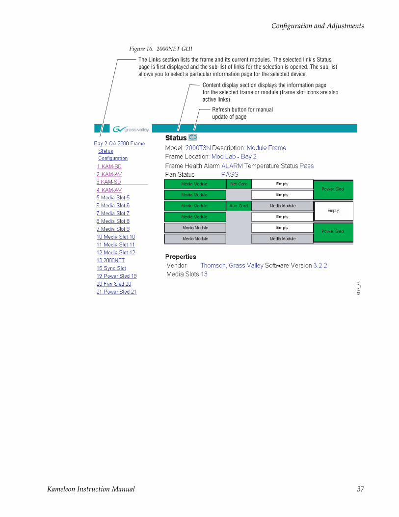
Figure 16. 2000NET GUI
8173
_32
The Links section lists the frame and its current modules. The selected link's Status page is first displayed and the sub-list of links for the selection is opened. The sub-list allows you to select a particular information page for the selected device.
Content display section displays the information page for the selected frame or module (frame slot icons are alsoactive links).
Refresh button for manual update of page
Kameleon Instruction Manual 37

Configuration and Adjustments
Web Page Operations and Functional ElementsThe following conventions and functional elements (shown at left) are used in Kameleon web page operations. (The examples shown throughout this manual represent 2000NET software version 3.2.2 or later):
• Pulldown menus allow you to choose selections from a list.
• Check boxes are used when a selection can be enabled or included in a group. Multiple check box selections or enables can be made for some parameters.
• Radio buttons are used to make a choice of one parameter in a group.
• Each numerical adjustment control has a Coarse adjust button (left and right top double arrows) and a Fine adjust button (left and right bottom single arrows).
To change a value, use the arrow button controls or enter a value into the number field and select the Apply button. You may also enter a number into the number field from a keyboard and hit the Enter key to apply the value.
• A Refresh button (circular arrow) is provided for manual refresh of the web page to view recently changed parameters.
• The Status LED is explained below.
Status and Identification Header Each Kameleon configuration page has a Status and Identification Header as shown in Figure 17.
Figure 17. Typical Status/ID Header
Status LED iconThe Status LED icon reports communication status for the frame slot and is a link to the module Status page where Warnings and Faults are displayed. LED colors indicate:
• Green = Pass – no problems detected
• Yellow = Configuration error warning
• Red = Fault condition detected
Pulldown Menus
Check box
Refresh button
Apply button
Coarse adjust
Status LED
Fine adjust
Radio button
8343
_06
8173
_29
Link toStatus page
Variables
38 Kameleon Instruction Manual

Configuration and Adjustments
Variables:
• Model and Description are read-only generated by the module.
• Frame Location is entered in 2000 Series Kameleon Frame configura-tion.
• Slot number reports the module’s location in the frame.
Initial Configuration Process OverviewTo configure the Kameleon module proceed as follows:
1. Go to the I/O Config page to setup and name inputs and outputs.
2. If not already connected, connect all input and output signals. Go to the module Status page to verify component and signal presence and condition.
3. Go to the Video Input Select page to configure the video source (not required for KAM-SD) and output timing source.
4. Go to DEMUX if you are demultiplexing audio from the video signal.
5. Go to the Functional Views page to:
• Verify the module’s functional configuration is correct, and
• Begin with the Input block links to configure each function in turn.
Note Next links are provided to help you navigate through a logical configuration sequence.
6. Use E-MEM memory to store or recall configurations as necessary.
Kameleon Instruction Manual 39

KAM-AV and KAM-SD Links and Web Pages
KAM-AV and KAM-SD Links and Web PagesThe 2000 GUI provides the following links and web pages for the KAM-SD and the KAM-AV modules (Figure 18):
• Status, I/O Config, and Functional View web pages showing
• Module operation status,
• Rear module I/O configuration.
• Functional block diagram showing active/inactive functional blocks and providing links to the related web pages,
• Module Configuration web pages for setting up the module,
• E-MEM configuration storage and recall web page, and
• Slot Configuration, SNMP, and software update web pages.
Logical subject links are also available on each configuration web page.
Note Some listed links may not appear when the Kameleon hardware configuration does not support that function. (For example, when no DAC submodule is installed, Analog Audio Output links will not appear.) When this occurs, the Functional View web page will indicate the related block is inactive (see Figure 27 on page 52 for the KAM-AV module and Figure 28 on page 53 for the KAM-SD module).
Figure 18. KAM-SD and KAM-AV Web Page Links
40 Kameleon Instruction Manual

KAM-AV and KAM-SD Links and Web Pages
Status Web PageThe Status web page for the KAM-AV (Figure 19 on page 42), KAM-SD module (Figure 20 on page 43), and KAM-AV or SD with extended rear modules (Figure 21 on page 44), provide an overall indication of the health of the system and links to web pages for the active components:
• Status Header – the same on all Kameleon configuration pages (see Web Page Operations and Functional Elements on page 38),
• Color-coded communication status for each component and path,
• Summary of all fault/warning conditions, and
• Textual module status, front module, and submodule properties.
Color-coded Status Indicators and LinksEach box on the Status page represents a Kameleon module or submodule as shown for example in Figure 19 on page 42. Arrows represent signal paths that may or may not be monitored. These elements act as links when their function is active (indicated by underlined function name).
Color code:
• Green = Pass – operating as expected.
• Yellow = Warning – signal is absent, has errors, or is misconfigured.
• Red = Fault – a component has failed.
• Grey = Not monitored.
• White = Not present.
Status/Front Module PropertiesThe Status/Front Module properties in the footer provide a textual summary of the color-coded module status. Front module properties provide hardware, firmware (different between the KAM-AV and KAM-SD and KAM-AV or SD modules using an extended rear module), software identification, and asset tag number for the KAM-SD or KAM-AV front processing module. ADC or DAC submodule properties are also reported if they are installed on the processing module.
Submodule PropertiesThe Submodule properties in the footer provide a textual summary of the color-coded submodule status. If the front module has the ADC or DAC submodule installed, the bottom of the Status web page will display part number, serial number, and hardware revision for each submodule.
Usethislink
Kameleon Instruction Manual 41

KAM-AV and KAM-SD Links and Web Pages
Figure 19. KAM-AV Status Web Page
Warning and Fault summary section
Firmware differs between modules
42 Kameleon Instruction Manual

KAM-AV and KAM-SD Links and Web Pages
Figure 20. KAM-SD Status Web Page
Warning and Fault summary section
Firmware differs between modules
Kameleon Instruction Manual 43

KAM-AV and KAM-SD Links and Web Pages
Figure 21. KAM-AV Status Web Page with Extended Rear Module
Warning and Fault summary section
Firmware differs between modules
44 Kameleon Instruction Manual

KAM-AV and KAM-SD Links and Web Pages
Warning/Fault SummaryThe warnings and faults shown below are reported in the summary section of the Status web page (Figure 19 on page 42). A Fault indicates a serious condition that prohibits proper operation. A Warning indicates a condition which may or may not adversely affect operating conditions, but should be noted. Warnings may possibly be corrected by changing configuration, set-tings or input signals.
Warnings
• WARNING - Rear Module is not connected
• WARNING - Wrong Rear Module (incompatible with Kameleon)
• WARNING - Wrong Rear Module (no communication)
• WARNING - Wrong Rear Module (unknown type, incompatible)
• WARNING - Video Input is 625 and reference is 525 lines
• WARNING - Video Input is 525 and reference is 625 lines
• WARNING - Video Input is 625 but configuration is 525 lines
• WARNING - Video Input is 525 but configuration is 625 lines
• WARNING - Video Input Signal not detected
• WARNING - Frame Reference is not present
• WARNING - Frame Reference is not locked to input
• WARNING - Frame Reference is not present
• WARNING - No Video output - GenLock selected but not present
• WARNING - 1 or more Audio Input signals not detected
• WARNING - 1 or more Audio Input signals have had AES stream errors
• Internal Error - Unknown submodule type
Faults
• FAULT - nnV power supply bad. (nn = variable: 24 V, 12.5 V, 5 V, 3.3 V, 1.5 V, -5 V, or -12.5 V)
• FAULT - A/D failed (A /D system measuring power supplies and bus levels)
• FAULT - Xilinx 1 failure (main video processor)
• FAULT - Xilinx 2 failure (main audio processor)
• FAULT - MFM (Multi-function module) EEPROM checksum fails
• FAULT - DS1803 not responding (digital video in adjustment)
• Internal Error - Unknown front module type
Kameleon Instruction Manual 45

KAM-AV and KAM-SD Links and Web Pages
Input/Output Configuration Web PageUse the I/O Config web page to:
• Assign easily recognized signal names that will help later in the config-uration process, and
• Configure AES audio ports as inputs or outputs, balanced or unbal-anced.
Figure 23 illustrates the KAM-AA-R Rear module I/O Config web page. The type of submodule in Position 1 will determine whether Analog Audio connectors J7-J10 are all inputs or all outputs. The type of submodule in Position 2 will determine whether Analog Audio connectors J2-J5 are all inputs or all outputs.
Refer to Table 2 on page 21 for submodule I/O combinations and Figure 10 on page 21 for cabling information.
Figure 22. KAM-AA-R Rear Module Configuration Web Page
Usethislink
46 Kameleon Instruction Manual
KAM-AV and KAM-SD Links and Web Pages
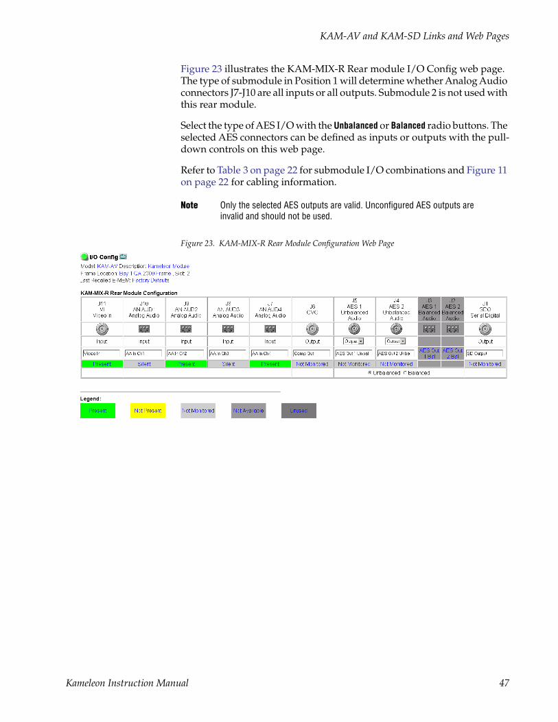
Figure 23 illustrates the KAM-MIX-R Rear module I/O Config web page. The type of submodule in Position 1 will determine whether Analog Audio connectors J7-J10 are all inputs or all outputs. Submodule 2 is not used with this rear module.
Select the type of AES I/O with the Unbalanced or Balanced radio buttons. The selected AES connectors can be defined as inputs or outputs with the pull-down controls on this web page.
Refer to Table 3 on page 22 for submodule I/O combinations and Figure 11 on page 22 for cabling information.
Note Only the selected AES outputs are valid. Unconfigured AES outputs are invalid and should not be used.
Figure 23. KAM-MIX-R Rear Module Configuration Web Page
Kameleon Instruction Manual 47
KAM-AV and KAM-SD Links and Web Pages
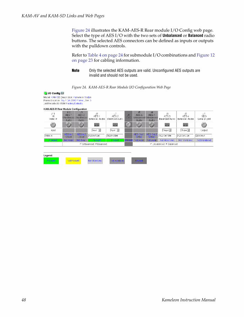
Figure 24 illustrates the KAM-AES-R Rear module I/O Config web page. Select the type of AES I/O with the two sets of Unbalanced or Balanced radio buttons. The selected AES connectors can be defined as inputs or outputs with the pulldown controls.
Refer to Table 4 on page 24 for submodule I/O combinations and Figure 12 on page 23 for cabling information.
Note Only the selected AES outputs are valid. Unconfigured AES outputs are invalid and should not be used.
Figure 24. KAM-AES-R Rear Module I/O Configuration Web Page
48 Kameleon Instruction Manual

KAM-AV and KAM-SD Links and Web Pages
Figure 25 illustrates the KAM-AA-AES-UR Rear module I/O Config web page. The type of submodule in Position 1 will determine whether Analog Audio connectors J8 and J9 are inputs or outputs. The submodule in Posi-tion 2 will determine whether Analog Audio connector J6 is an input or an output.
AES unbalanced connectors J2, J3, J4 and J5 can be defined as all inputs, all outputs, or 2 inputs and 2 outputs with the pulldown controls on this I/O web page.
Note If the KAM-AA-AES-UR Rear module is installed in a frame with a 2000NET card running version 3.2.2 software, the dual Analog Audio graphics will be shown as boxes with red X’s. The dual audio graphic is not recognized by this version 2000NET card. Functionality is not affected.
Refer to Table 6 on page 26 for submodule I/O combinations and Figure 13 on page 25 for cabling information.
Figure 25. KAM-AA-AES-UR Rear Module I/O Configuration Web Page
Kameleon Instruction Manual 49

KAM-AV and KAM-SD Links and Web Pages
I/O Config Page ElementsFour of the AES-Rear module audio connectors are shown in Figure 26 to illustrate the function of each row of the diagram.
Header RowThe top header row provides the connector hardware physical label (J#) and the dedicated signal type for the connector. This information is deter-mined by the type of rear module and front processor module installed (refer to the Functional View Web Page on page 52).
Figure 26. Balanced/Unbalanced AES/EBU Inputs
ConnectorsThe Connector row illustrates connector type provided (BNC or 3-pin ter-minal) for each port. Connector type and input/output possibilities vary according to the rear I/O module used or with the presence of ADC or DAC submodules.
Input/Output ModeI/O mode is either static read-only or an operational Input/Output selec-tion (determined by the rear module used).
Signal NameEnter a signal name (up to 15 characters) for each operational input/output. The name will be used to identify the signal in other config-uration pages.
Signal type
Input/Output Selection
Connector physical label
User input
Select active connector pair:unbalanced (BNC) or balanced (3-pin)
Gray sections are not available
Header
Connector
I/O mode
Signal name
Status
8173
_30
50 Kameleon Instruction Manual
KAM-AV and KAM-SD Links and Web Pages
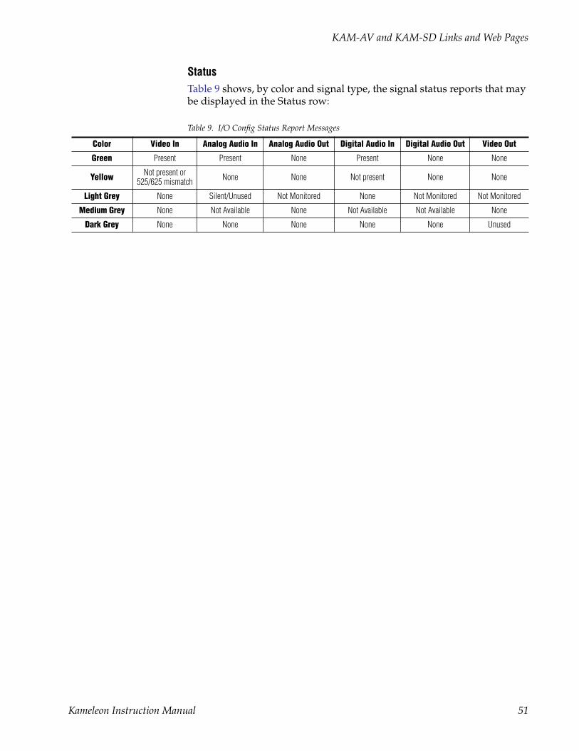
StatusTable 9 shows, by color and signal type, the signal status reports that may be displayed in the Status row:
Table 9. I/O Config Status Report Messages
Color Video In Analog Audio In Analog Audio Out Digital Audio In Digital Audio Out Video Out
Green Present Present None Present None None
Yellow Not present or 525/625 mismatch None None Not present None None
Light Grey None Silent/Unused Not Monitored None Not Monitored Not Monitored
Medium Grey None Not Available None Not Available Not Available None
Dark Grey None None None None None Unused
Kameleon Instruction Manual 51

KAM-AV and KAM-SD Links and Web Pages
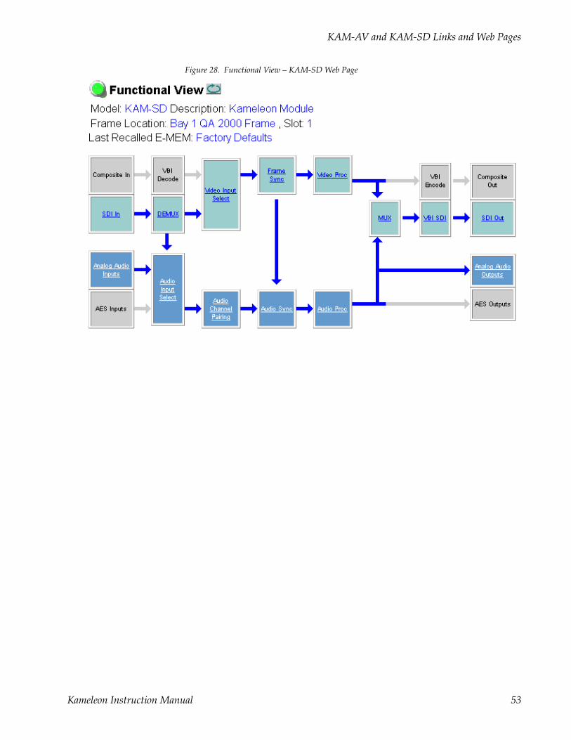
Functional View Web PageUse the Functional View web page (KAM-AV – Figure 27, KAM-SD – Figure 28 on page 53) to:
• Monitor module functions and signal paths, and
• Navigate to pages for configuring active functions.
The Functional View page is a block diagram of the installed Kameleon system that reports the module functions and signal paths that are active or inactive in the current configuration. It can be used as a link map for con-figuring module functions. Begin configuring with one of the input func-tion blocks on the left.
Color coding indicates active functions and flow. Greyed components are inactive due to hardware and/or software constraints. Underlined module functions are links to the page for that function. Return links and logical next step links are provided at the bottom of each configuration page.
Figure 27. Functional View – KAM-AV Web Page
Usethislink
52 Kameleon Instruction Manual
KAM-AV and KAM-SD Links and Web Pages
Figure 28. Functional View – KAM-SD Web Page
Kameleon Instruction Manual 53
KAM-AV and KAM-SD Links and Web Pages
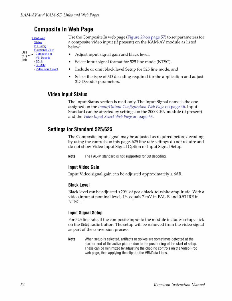
Composite In Web PageUse the Composite In web page (Figure 29 on page 57) to set parameters for a composite video input (if present) on the KAM-AV module as listed below:
• Adjust input signal gain and black level,
• Select input signal format for 525 line mode (NTSC),
• Include or omit black level Setup for 525 line mode, and
• Select the type of 3D decoding required for the application and adjust 3D Decoder parameters.
Video Input StatusThe Input Status section is read-only. The Input Signal name is the one assigned on the Input/Output Configuration Web Page on page 46. Input Standard can be affected by settings on the 2000GEN module (if present) and the Video Input Select Web Page on page 63.
Settings for Standard 525/625The Composite input signal may be adjusted as required before decoding by using the controls on this page. 625 line rate settings do not require and do not show Video Input Signal Option or Input Signal Setup.
Note The PAL-M standard is not supported for 3D decoding.
Input Video GainInput Video signal gain can be adjusted approximately ± 6dB.
Black LevelBlack level can be adjusted ±20% of peak black-to-white amplitude. With a video input at nominal level, 1% equals 7 mV in PAL-B and 0.93 IRE in NTSC.
Input Signal SetupFor 525 line rate, if the composite input to the module includes setup, click on the Setup radio button. The setup will be removed from the video signal as part of the conversion process.
Note When setup is selected, artifacts or spikes are sometimes detected at the start or end of the active picture due to the positioning of the start of setup. These can be minimized by adjusting the clipping controls on the Video Proc web page, then applying the clips to the VBI/Data Lines.
Usethislink
54 Kameleon Instruction Manual

KAM-AV and KAM-SD Links and Web Pages
3D Decoder ControlThe composite input is processed through a 3D decoder which offers three preset decoder modes and a user defined mode. Preset modes are selected according to the amount of motion present in the input video.
Each decoder mode has a set of default values when selected. User controls are provided for setting motion threshold, the type of comb filtering, luma and chroma threshold levels, and luma bandwidth.
To determine the best preset decoding mode for your application, select one of the 3D preset decoding modes at the bottom of the 3D Decoder Control section depending on the amount of motion in the input video:
• Low Motion – this is a 3D temporal filter ideal for applications where there is little motion in the video, such as scenes involving sitting and other scenes involving little motion.
• Mixed Motion – a general purpose filter, this is the default choice for most video applications involving mixed motion.
• High Motion – a 2D adaptive filter is employed for handling change in motion recommended for video where there will be a great deal of motion such as sports. Once motion is detected in a scene, the high motion decoder should be used.
• User Defined – changing any preset value in the Motion decoders will switch to the user mode.
After setting the preset decoder mode for the amount of motion in the video application, use the following controls to maximize video quality.
3D Motion ThresholdThis control sets the limit between the use of 3D or 2D adaptive decoding modes. 3D decoding is used below the motion threshold, otherwise the mode is 2D adaptive decoding. This decoding mode decision is automati-cally evaluated for each pixel.
As a general rule to get the best decoding result, it is recommended to reduce the motion threshold as the motion increases in the video. Use the default threshold values of each preset decoder as a guide to setting the 3D motion threshold and the correct preset decoder mode.
The preset modes and default thresholds are as follows:
• High Motion preset set the threshold to 5,
• Mixed Motion preset sets the threshold to 25, and
• Low Motion preset sets the threshold to 60.
The recommended mode is Mixed Motion which is the factory default mode.
Kameleon Instruction Manual 55

KAM-AV and KAM-SD Links and Web Pages
Comb FilterThe comb filter is part of the 2D adaptive comb filter mode. It determines what component of the video will be used to detect motion (Luma and Chroma or just the Luma or Chroma portion of the video).
• Luma + Chroma – when set for both luminance and chrominance, the 2D adaptive decoder motion detector is controlled by both the luminance and chrominance difference level magnitude.
• Luma – in this mode, the 2D adaptive decoder motion selector is con-trolled by only the luminance difference level magnitude in the video.
• Chroma – in this mode, the 2D adaptive decoder motion selector is con-trolled by only the chrominance difference level magnitude in the video.
Luma LevelThe Luma Level control sets the magnitude of the difference level threshold for the Y or luminance component of the video signal in the comb filter. The default value is 56.
Chroma LevelThe Chroma Level control sets the magnitude of the difference level threshold for the chrominance portion of the video signal in the comb filter. The default value is 56.
Luma BandwidthThe Luma Bandwidth sets the frequency at which the comb filtering occurs. It can be set for Narrow or Wide.
• Narrow – extends the 2D comb filter to lower frequencies and is the default bandwidth for the High Motion preset mode.
• Wide – allows 2D comb filtering only at higher frequencies. This is the Mixed and Low Motion default.
Note Narrow or Wide bandwidth may be selected according to the chrominance subcarrier frequency and chrominance bandwidth.
Reset 3D DecoderPress the Reset 3D Decoder to Default to return to the default Mixed Motion mode with the defaults listed in Table 8 on page 29.
56 Kameleon Instruction Manual

KAM-AV and KAM-SD Links and Web Pages
Figure 29. Composite Input Web Page
Kameleon Instruction Manual 57

KAM-AV and KAM-SD Links and Web Pages
VBI Decode Web Page for Composite InputUse the VBI decode web page (Figure 30 for 525, Figure 31 on page 59 for 625) to configure the VBI and Data Line decoding of the composite input signal (KAM-AV only).
The currently detected line rate will be reported. Use the View Selection to view the page at the correct line rate with the 525 or 625 radio button.
On a line-by-line basis you can remove black level setup (in NTSC video) and select one of the following three decoding options:
• Blank existing VBI and Data Line information,
• Select Notch Decoding of the composite signal, or
• Pass through decoded VBI and Data Lines (active video lines) informa-tion as is.
Note The data lines not reserved for carrying data on the previous page will appear greyed out.
Figure 30. VBI Decode Web Page (Composite Input, 525 Line Rate Shown)
Usethislink
58 Kameleon Instruction Manual

KAM-AV and KAM-SD Links and Web Pages
Figure 31. VBI Decode Web Page (Composite Input, 625 Line Rate Shown)
Kameleon Instruction Manual 59
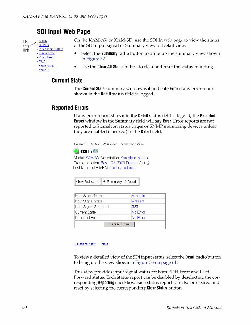
KAM-AV and KAM-SD Links and Web Pages
SDI Input Web PageOn the KAM-AV or KAM-SD, use the SDI In web page to view the status of the SDI input signal in Summary view or Detail view:
• Select the Summary radio button to bring up the summary view shown in Figure 32.
• Use the Clear All Status button to clear and reset the status reporting.
Current StateThe Current State summary window will indicate Error if any error report shown in the Detail status field is logged.
Reported ErrorsIf any error report shown in the Detail status field is logged, the Reported Errors window in the Summary field will say Error. Error reports are not reported to Kameleon status pages or SNMP monitoring devices unless they are enabled (checked) in the Detail field.
Figure 32. SDI In Web Page – Summary View
To view a detailed view of the SDI input status, select the Detail radio button to bring up the view shown in Figure 33 on page 61.
This view provides input signal status for both EDH Error and Feed Forward status. Each status report can be disabled by deselecting the cor-responding Reporting checkbox. Each status report can also be cleared and reset by selecting the corresponding Clear Status button.
Usethislink
60 Kameleon Instruction Manual
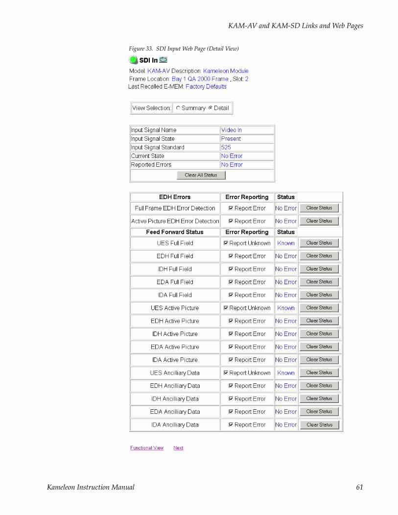
KAM-AV and KAM-SD Links and Web Pages
Figure 33. SDI Input Web Page (Detail View)
Kameleon Instruction Manual 61
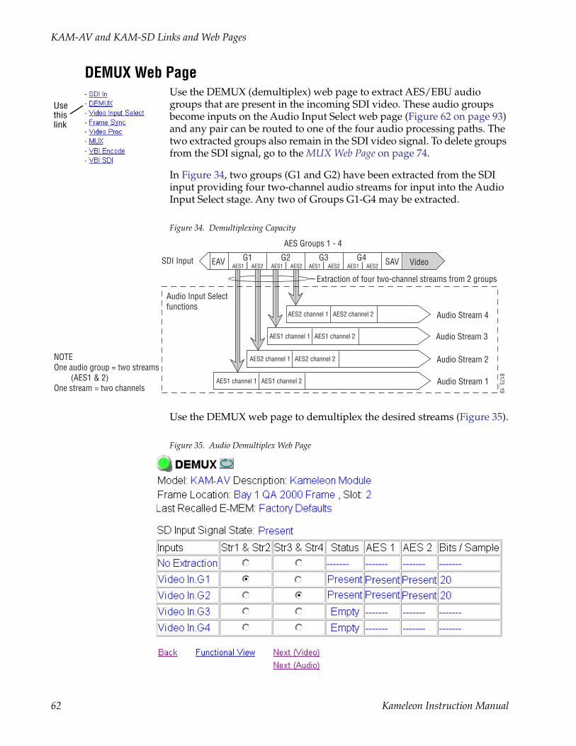
KAM-AV and KAM-SD Links and Web Pages
DEMUX Web PageUse the DEMUX (demultiplex) web page to extract AES/EBU audio groups that are present in the incoming SDI video. These audio groups become inputs on the Audio Input Select web page (Figure 62 on page 93) and any pair can be routed to one of the four audio processing paths. The two extracted groups also remain in the SDI video signal. To delete groups from the SDI signal, go to the MUX Web Page on page 74.
In Figure 34, two groups (G1 and G2) have been extracted from the SDI input providing four two-channel audio streams for input into the Audio Input Select stage. Any two of Groups G1-G4 may be extracted.
Figure 34. Demultiplexing Capacity
Use the DEMUX web page to demultiplex the desired streams (Figure 35).
Figure 35. Audio Demultiplex Web Page
Usethislink
VideoG4G3G2G1AES1 AES2 AES1 AES2 AES1 AES2 AES1 AES2
AES2 channel 1 AES2 channel 2
AES1 channel 1 AES1 channel 2
AES2 channel 1 AES2 channel 2
AES1 channel 1 AES1 channel 2
EAV SAVSDI Input
Audio Input Selectfunctions
NOTEOne audio group = two streams (AES1 & 2)One stream = two channels
8173_19
Audio Stream 4
Extraction of four two-channel streams from 2 groups
Audio Stream 3
Audio Stream 2
Audio Stream 1
AES Groups 1 - 4
62 Kameleon Instruction Manual

KAM-AV and KAM-SD Links and Web Pages
Video Input Select Web PageUse the Video Input Select web page (Figure 36 on page 65) to:
• Configure input video type and line rate,
• Enable or disable Loss of Signal reporting to the Status page and SNMP monitoring (refer to the 2000NET manual for SNMP information),
• Configure Vertical Blanking Interval (in Advanced mode), and
• Select the output timing reference.
View SettingIn the View Selection display, choose the Standard radio button to display the standard settings shown in Figure 36 on page 65. Use the Advanced view for configuring the Vertical Blanking Interval for selecting active video lines to carry data (see Advanced VBI Configuration on page 66).
Video Selection SettingsThe following functions are provided in the Video Selection section:
• Input Name – (read-only) signal name is entered on the I/O Config page
• Input Status –
• Signal presence reported
• Enable/disable Loss of Signal report to both Kameleon status pages and SNMP monitoring devices.
Note The disabling of video and reference Loss of Signal reports and SDI Input Error warnings allow you to filter these reports from higher level Kameleon status displays and SNMP monitoring. They will still be reported on this page.
• Video Format –
• Current input video format reported.
• Choose between SDI and Composite video format or select Auto-matic signal format detection.
• Video Line Rate – select 525 or 625 line rate or enable automatic line rate detection.
• Flywheel Video Decoder – use of the Flywheel Video Decoder is recom-mended when working with noisy input signals, such as satellite feeds. Once the optimum input signal has been acquired, turn the Flywheel Video Decoder off during normal operation.
For best results, turn the Flywheel Video Decoder on by selecting the On checkbox and set the Output Timing Selection source to Video In. Locate the optimum video input signal, then turn the flywheel off (uncheck).
Usethislink
Kameleon Instruction Manual 63

KAM-AV and KAM-SD Links and Web Pages
When the Flywheel Video Decoder is turned on, a caution will appear as shown in Figure 36 on page 65. Since the Flywheel decoder generates its own video timing for the incoming video stream to deal with noise and interruptions, leaving it on during normal operation may cause undesirable re synchronization delays if the source changes or is lost. It will take about 7 seconds to change states.
• Frame Reference –
• 2000GEN frame reference signal presence reported,
• Enable/disable Loss of Signal report to both Kameleon status pages and SNMP monitoring devices.
• SDI Input Errors – displayed only for SDI input (SDI or Auto)
• ‘Input signal errors reported.
• Enable/disable SDI error warning report to both Kameleon status pages and SNMP monitoring devices.
• Frame Sync/Delay – (read-only) Frame Sync mode is reported when Output Timing Selection is Internal Frame Reference and timing is pro-vided from the 2000GEN module. Delay mode is reported when the input signal (Video In) is used for timing reference
Output Timing SelectionIf you have a 2000GEN reference module installed in the frame and want the Kameleon to work as a frame synchronizer, set the output timing source to Internal Frame Reference. Otherwise, set the output timing source to Video In.
Note For correct composite out color framing in PAL-B, always use the Internal Frame Reference.
Note When a video input with embedded audio is switched, the audio will mute when the module is set to Delay mode (Video In reference). To avoid any audio muting, use the Internal Frame reference (Frame Sync).
64 Kameleon Instruction Manual
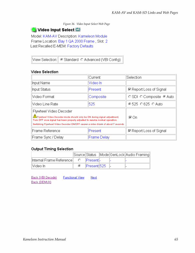
KAM-AV and KAM-SD Links and Web Pages
Figure 36. Video Input Select Web Page
Kameleon Instruction Manual 65

KAM-AV and KAM-SD Links and Web Pages
Advanced VBI Configuration Advanced VBI configuration allows you extend VBI into the active picture range for special data insertion requirements. Active video lines that are used to carry data are referred to as Data Lines.
To add Data Lines to VBI:
1. Choose Advanced (VBI Config) on the Video Input Select web page (Figure 37).
Figure 37. Standard and Advanced View Selection
The VBI/Data Lines panel will appear at the bottom of the web page (see Figure 38 on page 67 for 525 line rate and Figure 39 on page 67 for 625 line rate).
2. Select the last line (includes all previous active video lines) that will be used for data.
Selected active video lines will be shown in the Reserved for Data section of the web page as shown for lines 21/284 and 22/285 in Figure 38 on page 67 and lines 24/337 and 25/338 in Figure 39 on page 67.
Active video lines that can be made available for data insertion are:
• For 525, lines 21 – 24 in Field 1, lines 284 – 287 in Field 2
• For 625, lines 24 – 28 in Field 1, lines 337 – 341 in Field 2
66 Kameleon Instruction Manual
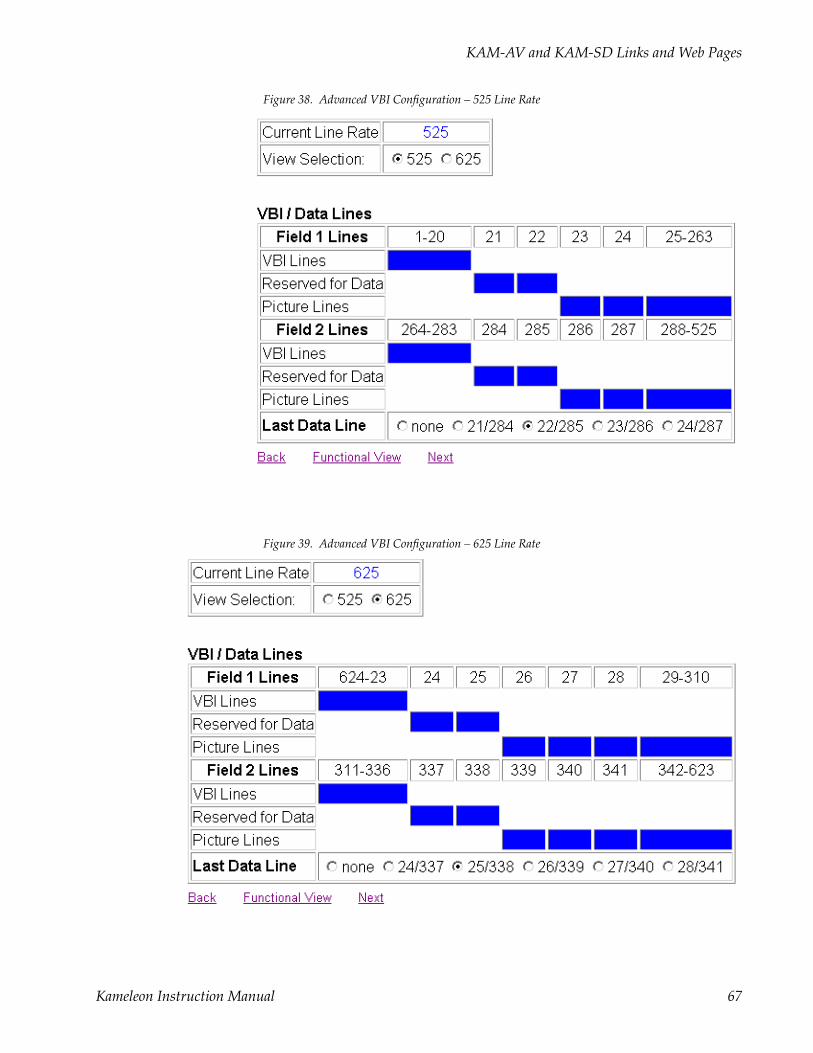
KAM-AV and KAM-SD Links and Web Pages
Figure 38. Advanced VBI Configuration – 525 Line Rate
Figure 39. Advanced VBI Configuration – 625 Line Rate
Kameleon Instruction Manual 67

KAM-AV and KAM-SD Links and Web Pages
Frame Sync Web PageUse the Frame Sync web page to:
• Adjust horizontal and vertical timing, and
• Freeze the current output or, if using a 2000GEN reference signal, select an automatic freeze mode for output when the signal is lost.
Timing AdjustmentTable 10 shows the ranges of timing for 525 and 625 signal formats.
Freeze Mode SelectionThe Freeze mode controls available depend on the output timing reference selected on the Video Input Select Web Page on page 63.
Frame Sync mode (using the 2000GEN Internal Frame Reference output timing reference) provides the manual activation selections plus AutoBlack and AutoFreeze modes to be used when the video signal is lost (Figure 40 on page 69). AutoBlack outputs a black signal while AutoFreeze outputs the last complete video field.
When set to Frame Delay mode (using the Video In output timing reference), Freeze Mode allows you to manually freeze the output using Field 1, Field 2, or one Frame (Figure 41 on page 69). A field freeze provides less resolution and no motion artifacts in the output. In Frame mode the resolution is higher since both fields are present, but the presentation of two fields can cause motion artifacts.
Table 10. Timing Adjustment Ranges
Line Rate Max Horizontal Adjustment Max Vertical Adjustment
525/NTSC 857.5 pixels 524 lines
625/PAL 863.5 pixels 624 lines
Usethislink
68 Kameleon Instruction Manual

KAM-AV and KAM-SD Links and Web Pages
Figure 40. Frame Synchronizer Web Page – Internal Frame Reference
Figure 41. Frame Synchronizer Web Page – Video In Reference
Kameleon Instruction Manual 69
KAM-AV and KAM-SD Links and Web Pages
Video Processing Web PageUse the Video Processing page (Figure 42 on page 71) to:
• Enable/disable Standard or Advanced video processing,
• Turn on Color Bars test signal,
• Enable/disable video gain lock,
• Adjust component video gain (Y, B-Y, R-Y),
• Adjust component video DC Offset (Y, B-Y, R-Y),
• Enable/disable soft and hard clipping controls, and
• Apply selected clip settings to VBI/Data lines.
Video Processing Controls
Video Processing EnableTo bypass Video Processing on the SDI signal select Disable (Figure 42 on page 71). To make video processing adjustments to the SDI signal select Enable or select Color Bars to use the internally generated 100% vertical color bars test signal.
Two modes of video processing are available, Standard or Advanced. With Standard selected, only the Y Channel Video Processing controls on the left will be visible along with the clipping controls.
When Advanced is selected, the B-Y and R-Y Gain and Balance/Offset con-trols will also be displayed as shown in Figure 43 on page 73.
Standard ViewIn Standard View (Figure 42 on page 71), adjust the following for the Y Channel:
• Contrast/Y Gain – adjust the percentage of luminance relative to white (50 to 149.6%).
• Saturation/Chroma Gain – adjust the percentage of saturation and chroma gain relative to 100% saturation (50 to 149.6%).
• Brightness/Y Offset – adjust the amount of brightness/Y offset in mV (-3.55 to 3.44%)
• Hue/Chroma Phase – for 525 signals only, adjust the hue/chroma phase in degrees (-89.8 to 89.8 degrees).
Usethislink
70 Kameleon Instruction Manual

KAM-AV and KAM-SD Links and Web Pages
Figure 42. Video Processing Web Page
Kameleon Instruction Manual 71

KAM-AV and KAM-SD Links and Web Pages
Clipping ControlsClipping controls are provided that affect the luminance (soft/Y) and overall saturation (hard/video) levels of the output signal.
Refer to Figure 42 on page 71. To enable the clip controls select the Enable radio button. You may also apply the clip levels to the vertical blanking interval by checking the Apply Clips to VBI/Data Lines box. This control is also available on the VBI SDI web page (page 81).
Use the following clipping controls to adjust levels on the video output:
• Use the Soft/Y White Clip control to set the clipping level for the top end (white) of the luminance signal (positive excursions).
• Use the Soft/Y Black Clip control to set the clipping level for the bottom end (black) of the luminance signal (negative spikes and Super Black).
• Use the Hard/Video White Clip control to set the clipping level for the top end (white) of the overall video signal (clips white and reduces overall saturation level to fit within clip).
• Use the Hard/Video Black Clip control to set the clipping level for the bottom end (black) of the overall video signal (clips black and reduces overall saturation level to fit within clip).
Advanced ViewIn Advanced View (Figure 43 on page 73), adjust the following for the B-Y and R-Y Channels:
Note To adjust gain for all channels simultaneously, set Video Gain Lock to On. This locks Y, B-Y, and R-Y adjustments together. Adjustment of one gain setting changes all gain values (Y, B-Y, R-Y) the same amount.
• B-Y/R-Y Gain – adjust the percentage of B-Y and R-Y gain relative to 100% (50 to 149.6%).
• B-Y/R-Y Balance/Offset – adjust the amount of B-Y and R-Y DC offset in mV (-3.55 to 3.44%)
Reset To DefaultSelect the Reset To Default button on the bottom of the screen to return all values to the factory defaults.
72 Kameleon Instruction Manual
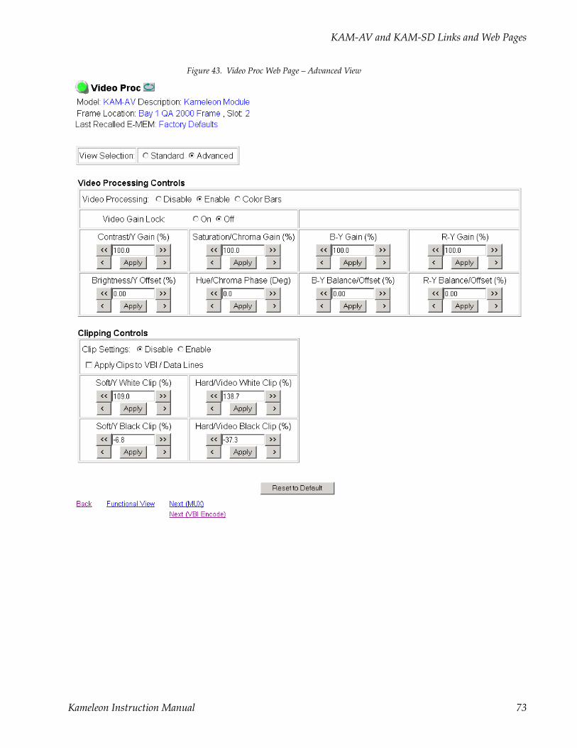
KAM-AV and KAM-SD Links and Web Pages
Figure 43. Video Proc Web Page – Advanced View
Kameleon Instruction Manual 73

KAM-AV and KAM-SD Links and Web Pages
MUX Web Page Use the MUX (multiplex) web page to:
• Delete unwanted audio groups from the SDI input video signal or clear all horizontal ancillary data (HANC), and
• Insert or replace audio groups into the SDI video stream that have been selected on the Audio Input Select web page, paired on the Audio Channel Pairing web page and configured in the Audio Proc, Audio Sync, and Audio Delay web pages.
Note The audio channel pairs available to each Mux Group below are determined by the Audio Channel Pairing web page (see page 94).
Note The Kameleon multiplexing circuit assumes there are no gaps between Groups in the input SDI video signal. If there are gaps, and one or more groups are inserted or replaced, all input Groups after the gap will be removed.
The MUX web page provides two functions: Group Deletion and Group Replacement.
Group DeletionThe Group Deletion area of the MUX web page reports if an embedded audio signal is present in any of the four possible audio groups in the incoming SDI signal and the output status of each group. It is the same as the Status reporting on the DEMUX web page (Figure 35 on page 62). It can be used to delete unwanted embedded audio groups or clear all HANC (horizontal ancillary data) in the SDI video input signal if present.
Composite Video InputWhen composite video is selected as the input to the module (no embedded audio is possible), the MUX web page Group Deletion section will appear as shown in Figure 44 with the Delete and No Input HANC data to clear greyed out.
Figure 44. Composite Video Input
Usethislink
74 Kameleon Instruction Manual

KAM-AV and KAM-SD Links and Web Pages
No Embedded AudioIf no embedded audio groups are present in the incoming SDI signal, the Group Deletion input status section will appear as shown in Figure 45. Input Status is Not Present and Output Status is Empty for each audio group. No deletion or Group Replacement is possible with this status.
Figure 45. No Embedded Audio Present
Pass and Delete Embedded AudioIf an embedded audio group is present in the incoming SDI signal and has been selected for No Extraction on the DEMUX web page, the audio group will be passed to the output as shown in Figure 46. Input Status is Present and Output Status is Passed.
Audio groups present in the incoming SDI stream may also be deleted. Check the corresponding Delete checkbox to remove an audio group com-pletely that is reported as Present from the SDI stream. The Output Status will report Deleted.
Figure 46. Pass and Delete Embedded Audio
Kameleon Instruction Manual 75
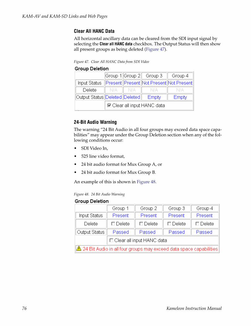
KAM-AV and KAM-SD Links and Web Pages
Clear All HANC DataAll horizontal ancillary data can be cleared from the SDI input signal by selecting the Clear all HANC data checkbox. The Output Status will then show all present groups as being deleted (Figure 47).
Figure 47. Clear All HANC Data from SDI Video
24-Bit Audio WarningThe warning “24 Bit Audio in all four groups may exceed data space capa-bilities” may appear under the Group Deletion section when any of the fol-lowing conditions occur:
• SDI Video In,
• 525 line video format,
• 24 bit audio format for Mux Group A, or
• 24 bit audio format for Mux Group B.
An example of this is shown in Figure 48.
Figure 48. 24 Bit Audio Warning
76 Kameleon Instruction Manual
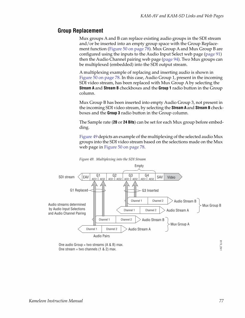
KAM-AV and KAM-SD Links and Web Pages
Group ReplacementMux groups A and B can replace existing audio groups in the SDI stream and/or be inserted into an empty group space with the Group Replace-ment function (Figure 50 on page 78). Mux Group A and Mux Group B are configured using the inputs to the Audio Input Select web page (page 91) then the Audio Channel pairing web page (page 94). Two Mux groups can be multiplexed (embedded) into the SDI output stream.
A multiplexing example of replacing and inserting audio is shown in Figure 50 on page 78. In this case, Audio Group 1, present in the incoming SDI video stream, has been replaced with Mux Group A by selecting the Stream A and Stream B checkboxes and the Group 1 radio button in the Group column.
Mux Group B has been inserted into empty Audio Group 3, not present in the incoming SDI video stream, by selecting the Stream A and Stream B check-boxes and the Group 3 radio button in the Group column.
The Sample rate (20 or 24 Bits) can be set for each Mux group before embed-ding.
Figure 49 depicts an example of the multiplexing of the selected audio Mux groups into the SDI video stream based on the selections made on the Mux web page in Figure 50 on page 78.
Figure 49. Multiplexing into the SDI Stream
Channel 1 Channel 2
Channel 1 Channel 2
Channel 1 Channel 2
Channel 1 Channel 2
Audio Pairs
SDI stream
G1 Replaced
Audio streams determinedby Audio Input Selectionsand Audio Channel Pairing
One audio Group = two streams (A & B) max. One stream = two channels (1 & 2) max.
8173_20r1
VideoG4G3G2G1AES1 AES2 AES1 AES2 AES1 AES2 AES1 AES2
EAV SAV
Audio Stream B
Audio Stream A
Audio Stream B
Audio Stream A
Empty
Mux Group A
Mux Group B
G3 Inserted
Kameleon Instruction Manual 77

KAM-AV and KAM-SD Links and Web Pages
Figure 50. MUX Web Page – Replace and Insert Audio
78 Kameleon Instruction Manual

KAM-AV and KAM-SD Links and Web Pages
VBI Encode Web Page for Composite OutputUse the VBI Encode web page (Figure 51 for 525, Figure 52 on page 80 for 625 line rate) to configure the VBI and Data Line encoding for the com-posite output signal (KAM-AV module only).
The currently detected line rate will be reported. Use the View Selection to view the web page at the correct line rate with the 525 or 625 radio button.
This web page allows you to do the following on a line-by-line basis:
• Blank existing VBI and Data Line information
• Remove black level setup (in 525 line rate only)
You may also apply the clipping done in the Video Processor to all VBI lines by checking the Apply Clips to VBI/Data Lines checkbox.
Note The data lines not reserved for carrying data on the Video Input Select web page will appear greyed out. See Advanced VBI Configuration on page 66.
Figure 51. VBI Encode Web Page – 525 Line Rate
Usethislink
Data lines configured inAdvanced VBI view onVideo Input Select web page
Kameleon Instruction Manual 79

KAM-AV and KAM-SD Links and Web Pages
Figure 52. VBI Encode Web Page – 625 Line Rate
Data lines configured inAdvanced VBI view onVideo Input Select web page
80 Kameleon Instruction Manual
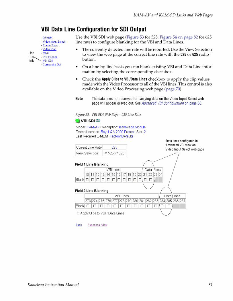
KAM-AV and KAM-SD Links and Web Pages
VBI Data Line Configuration for SDI OutputUse the VBI SDI web page (Figure 53 for 525, Figure 54 on page 82 for 625 line rate) to configure blanking for the VBI and Data Lines.
• The currently detected line rate will be reported. Use the View Selection to view the web page at the correct line rate with the 525 or 625 radio button.
• On a line-by-line basis you can blank existing VBI and Data Line infor-mation by selecting the corresponding checkbox.
• Check the Apply Clips to VBI/Data Lines checkbox to apply the clip values made with the Video Processor to all of the VBI lines. This control is also available on the Video Processing web page (page 70).
Note The data lines not reserved for carrying data on the Video Input Select web page will appear grayed out. See Advanced VBI Configuration on page 66.
Figure 53. VBI SDI Web Page – 525 Line Rate
Usethislink
Data lines configured inAdvanced VBI view onVideo Input Select web page
Kameleon Instruction Manual 81

KAM-AV and KAM-SD Links and Web Pages
Figure 54. VBI SDI Web Page – 625 Line Rate
Data lines configured inAdvanced VBI view onVideo Input Select web page
82 Kameleon Instruction Manual
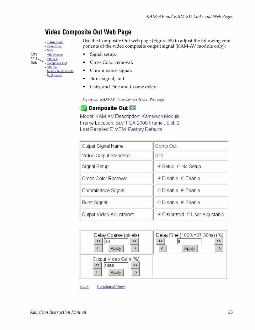
KAM-AV and KAM-SD Links and Web Pages
Video Composite Out Web PageUse the Composite Out web page (Figure 55) to adjust the following com-ponents of the video composite output signal (KAM-AV module only):
• Signal setup,
• Cross Color removal,
• Chrominance signal,
• Burst signal, and
• Gain, and Fine and Coarse delay.
Figure 55. KAM-AV Video Composite Out Web Page
Usethislink
Kameleon Instruction Manual 83

KAM-AV and KAM-SD Links and Web Pages
Signal SetupFor 525 standard composite, select Setup to add setup to the output or No Setup to not add it to the composite output.
Cross Color RemovalEnable Cross Color Removal filtering for a composite signal that displays unwanted luminance and chrominance artifacts produced during encoding of the signal.
Chrominance RemovalEnable Chrominance Removal to completely remove the chrominance portion of the composite output signal.
Burst RemovalEnable Burst Removal to completely remove the burst portion of the com-posite output signal.
Output Video AdjustmentsGain and coarse/fine delay of the composite output signal can be set to cal-ibrated values by selecting the Calibrated button. The delay settings are inde-pendent of the Frame Sync and SDI Video output controls.
If User Adjustable is selected use the following controls to adjust the com-posite output:
• Delay Coarse – adjusts the output delay in coarse steps of 5 pixels (double arrows) or 0.5 pixels (single arrows). The coarse delay range is from 0–4095 pixels.
• Delay Fine – adjusts the percent of output delay in fine steps of 10 percent (double arrows) o r1.0 percent (single arrows). The fine delay range is from 0–100% (100% = 37-38 ns)
• Output Video Gain – adjusts the output video gain in steps of 5 percent (double arrows) or 0.5 percent (single arrows). The output gain range is approximately 61–138.5 percent.
84 Kameleon Instruction Manual
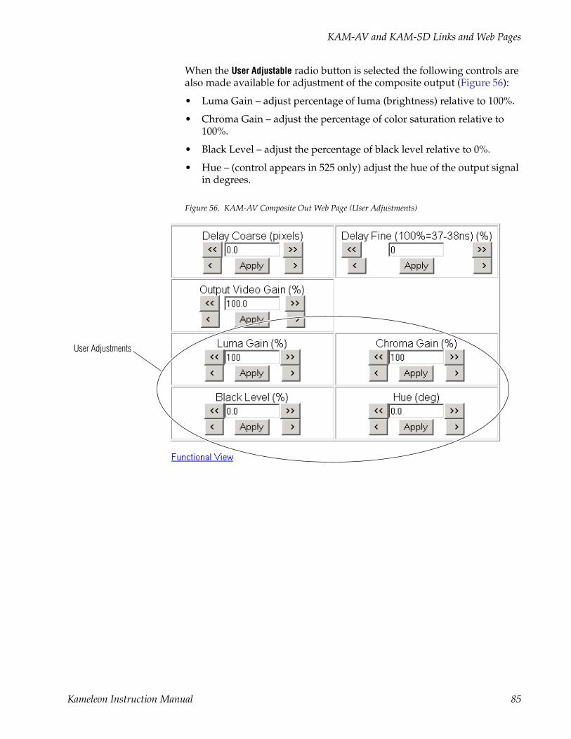
KAM-AV and KAM-SD Links and Web Pages
When the User Adjustable radio button is selected the following controls are also made available for adjustment of the composite output (Figure 56):
• Luma Gain – adjust percentage of luma (brightness) relative to 100%.
• Chroma Gain – adjust the percentage of color saturation relative to 100%.
• Black Level – adjust the percentage of black level relative to 0%.
• Hue – (control appears in 525 only) adjust the hue of the output signal in degrees.
Figure 56. KAM-AV Composite Out Web Page (User Adjustments)
User Adjustments
Kameleon Instruction Manual 85

KAM-AV and KAM-SD Links and Web Pages
SDI Out Web PageUse the SDI Out web page (Figure 57) to adjust the coarse delay of the SDI output signal independent of the Frame Sync and Composite Video con-trols. This page is present only for the KAM-AV module.
Figure 57. KAM-AV Video SDI Out Web Page
Output Delay CoarseThis web page provides an output delay coarse timing adjustment for the Video SDI Output signal only. This adjustment does not affect the Frame Sync timing or the Composite Video Output.
Adjust the output delay in coarse steps of 5 pixels (double arrows) or 0.5 pixels (single arrows). The coarse delay range is from 0–4095 pixels.
Usethislink
86 Kameleon Instruction Manual

KAM-AV and KAM-SD Links and Web Pages
Analog Audio Inputs Web PageThe Analog Audio Inputs web page is present when a KAM-ADC sub-module is installed on the front media module in position 1 or position 2. Analog audio inputs are available from a KAM-AA-R, KAM-MIX-R, or KAM-AA-AES-UR rear module.
Use the Analog Audio Inputs web page (Figure 58 for KAM-AA-R and KAM-MIX-R) to view the signal present and clipping status of the analog audio inputs and set maximum input levels. The web page for an extended rear module (with dual analog audio inputs) such as a KAM-AA-AES-UR, is shown in Figure 59 on page 88.
These audio groups become inputs on the Audio Input Select web page (Figure 62 on page 93) and any pair can be routed to one of the four audio processing paths.
Figure 58. Analog Audio Inputs Web Page
Usethislink
Kameleon Instruction Manual 87
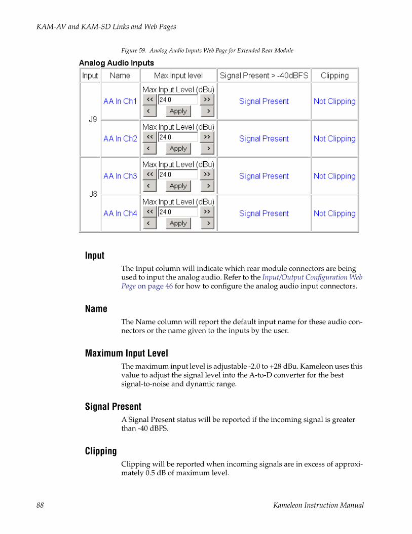
KAM-AV and KAM-SD Links and Web Pages
Figure 59. Analog Audio Inputs Web Page for Extended Rear Module
InputThe Input column will indicate which rear module connectors are being used to input the analog audio. Refer to the Input/Output Configuration Web Page on page 46 for how to configure the analog audio input connectors.
NameThe Name column will report the default input name for these audio con-nectors or the name given to the inputs by the user.
Maximum Input LevelThe maximum input level is adjustable -2.0 to +28 dBu. Kameleon uses this value to adjust the signal level into the A-to-D converter for the best signal-to-noise and dynamic range.
Signal PresentA Signal Present status will be reported if the incoming signal is greater than -40 dBFS.
ClippingClipping will be reported when incoming signals are in excess of approxi-mately 0.5 dB of maximum level.
88 Kameleon Instruction Manual

KAM-AV and KAM-SD Links and Web Pages
AES Inputs Web PageUse the AES Inputs web page (Figure 60) to check AES/EBU input signal status decoded from the input signal status bits.
These audio groups become inputs on the Audio Input Select web page (Figure 62 on page 93) and any pair can be routed to one of the four audio processing paths.
Figure 60. AES/EBU Audio Inputs Web Page
InputThe Input column will indicate which rear module connectors are being used to input AES audio depending on the type of rear module installed. Refer to the Input/Output Configuration Web Page on page 46 for how to con-figure the AES input connectors.
NameThe Name column will report the default input name for these audio con-nectors or the name given to the inputs by the user.
Signal StateThe signal state of the AES audio will be reported as Present or Not Present.
Sample RateKameleon accepts AES/EBU input signals at sample rates from 31 kHz to 96 kHz. The currently detected sample rate will be reported.
Usethislink
Kameleon Instruction Manual 89
KAM-AV and KAM-SD Links and Web Pages
ModeAll Kameleon audio processing is done in 24-bit mode. 20-bit input signals are converted to 24-bits using dithering probability. 20- or 24-bit output mode is selectable on later pages for AES/EBU and multiplexed (SDI) out-puts.
EmphasisCh1 and Ch2 Emphasis windows report whether high frequency emphasis is present (On/Off) on the audio input signal. Emphasis is high frequency gain adjustment that can conform to 50/15 µs or CCIT J.17 standards.
DataThe Ch1 and Ch2 Data windows report whether the input channels contain standard AES/EBU Audio or Data.
AES Errors DetectedUse the Clear button to refresh the AES Errors Detected in the AES Errors Detected column.
90 Kameleon Instruction Manual
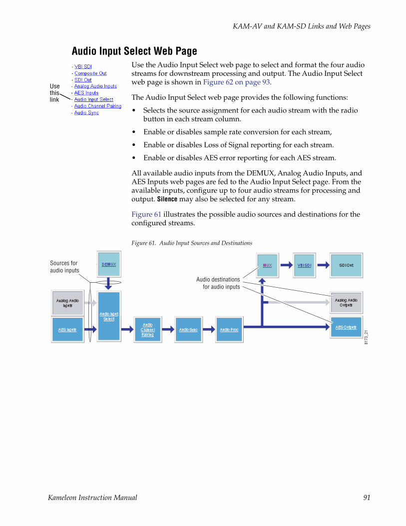
KAM-AV and KAM-SD Links and Web Pages
Audio Input Select Web PageUse the Audio Input Select web page to select and format the four audio streams for downstream processing and output. The Audio Input Select web page is shown in Figure 62 on page 93.
The Audio Input Select web page provides the following functions:
• Selects the source assignment for each audio stream with the radio button in each stream column.
• Enable or disables sample rate conversion for each stream,
• Enable or disables Loss of Signal reporting for each stream.
• Enable or disables AES error reporting for each AES stream.
All available audio inputs from the DEMUX, Analog Audio Inputs, and AES Inputs web pages are fed to the Audio Input Select page. From the available inputs, configure up to four audio streams for processing and output. Silence may also be selected for any stream.
Figure 61 illustrates the possible audio sources and destinations for the configured streams.
Figure 61. Audio Input Sources and Destinations
Usethislink
Sources for audio inputs
Audio destinationsfor audio inputs
8173
_21
Kameleon Instruction Manual 91

KAM-AV and KAM-SD Links and Web Pages
Refer to Figure 62 on page 93 for the following explanations.
Input Stream SelectAll available audio inputs are listed on the Audio Input Select web page with the names defined on the I/O Config web page. For this example, module default names are used.
Select the desired Stream 1-4 by selecting the corresponding radio button for that input.
StatusThe status of each of the selected inputs is reported as Present or Not Present.
Sample Rate ConvertOn demultiplexed and AES audio inputs, select whether to disable sample rate conversion on each stream. This does not apply to analog audio inputs.
Loss of Signal ReportingEnable or disable loss of signal reporting for each stream to higher levels such as SNMP reporting. This does not apply to analog audio inputs.
ReportingThe Reporting row will display what status is being reported to the higher levels. When Reporting is unchecked, the display will report Not Monitored.
AES ErrorsEnable or disable AES error reporting to higher levels. This is not appli-cable for analog or demultiplexed digital audio signals.
92 Kameleon Instruction Manual
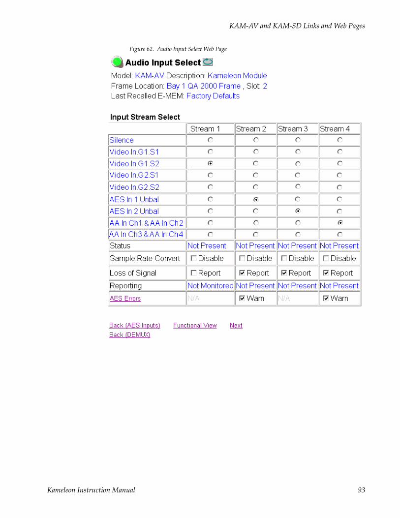
KAM-AV and KAM-SD Links and Web Pages
Figure 62. Audio Input Select Web Page
Kameleon Instruction Manual 93
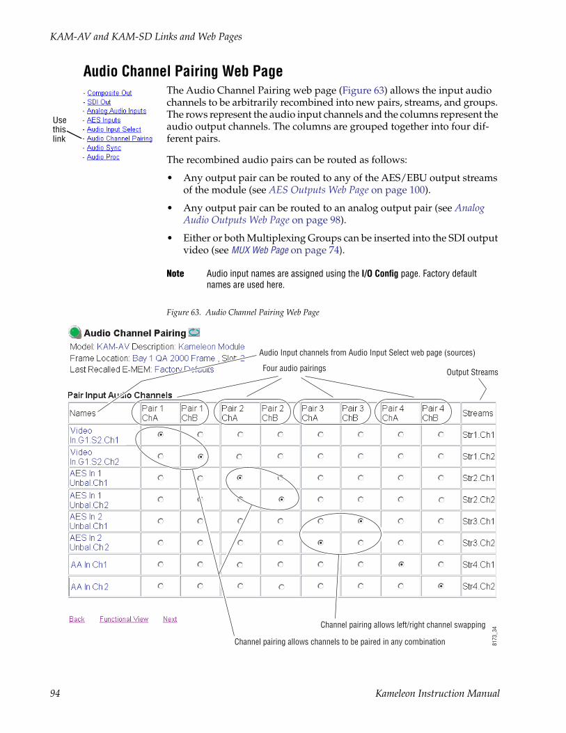
KAM-AV and KAM-SD Links and Web Pages
Audio Channel Pairing Web PageThe Audio Channel Pairing web page (Figure 63) allows the input audio channels to be arbitrarily recombined into new pairs, streams, and groups. The rows represent the audio input channels and the columns represent the audio output channels. The columns are grouped together into four dif-ferent pairs.
The recombined audio pairs can be routed as follows:
• Any output pair can be routed to any of the AES/EBU output streams of the module (see AES Outputs Web Page on page 100).
• Any output pair can be routed to an analog output pair (see Analog Audio Outputs Web Page on page 98).
• Either or both Multiplexing Groups can be inserted into the SDI output video (see MUX Web Page on page 74).
Note Audio input names are assigned using the I/O Config page. Factory default names are used here.
Figure 63. Audio Channel Pairing Web Page
Usethislink
Audio Input channels from Audio Input Select web page (sources)
Four audio pairings
Channel pairing allows left/right channel swapping
Channel pairing allows channels to be paired in any combination
Output Streams
8173
_34
94 Kameleon Instruction Manual

KAM-AV and KAM-SD Links and Web Pages
Audio Sync Web PageUse the Audio Sync web page (Figure 64) to:
• Synchronize the four audio channel pairs to Video Frame Sync, and/or
• Add audio delay using the delay adjust controls.
Use the Pair Selection radio buttons to select either Pairs 1 & 2 or Pairs 3 & 4 for adjustment.
Figure 64. Audio Synchronizer Web Page
Usethislink
Kameleon Instruction Manual 95

KAM-AV and KAM-SD Links and Web Pages
Audio Processing Web PageUse the Audio Proc web page (Figure 65 on page 97) to adjust the following for Audio Pair 1 & 2 and Audio Pair 3 & 4:
• Adjust audio signal gain for each channel or the two audio pairs,
• Lock gain settings for simultaneous channel A/channel B adjustment,
• Select a processing option for each channel.
Use the Pair Selection radio buttons to select either Pairs 1 & 2 or Pairs 3 & 4 for adjustment.
Audio GainEach audio channel can be adjusted for gain separately or in pairs. Use the following adjustments for audio gain:
• To lock the two channels in a pair together, select the Gain Settings Locked checkbox for Pair 1 and/or Pair 2.
• Adjust the gain (-40 to +6 dB) for each channel with the Ch A Gain Adjust and Ch B Gain adjust controls for each pair. If the pair is locked, adjusting either control will set the gain to the same value for each channel in the pair.
Note After gain has been adjusted, a straight quote mark (') will be added to Ch A' and Ch B' to indicate the status of the channels after gain.
Output ProcessingSet the output processing for each channel with the Processing pulldown to one of the following:
• Pass
• Invert
• A+B
• A-B
• -(A+B)
• 1 kHz (test tone)
• 400 Hz (test tone)
• Silence
• A + B (Pair 1, Pair 2, Pair 3 or Pair 4)
The Presence and Clipping status of each audio channel is reported as True or False in the read-only displays. If the audio is > -40 dBFS, it will be reported as True. If clipping is < 0.5 dBFS, it will be reported as False as shown in Figure 65 on page 97.
Usethislink
96 Kameleon Instruction Manual

KAM-AV and KAM-SD Links and Web Pages
Selecting Output ResolutionSelect the AES output resolution for Pair 1, Pair 2, Pair 3, and Pair 4 with the 20 bit or 24 bit radio button.
Figure 65. Audio Processing Configuration Web Page
Kameleon Instruction Manual 97

KAM-AV and KAM-SD Links and Web Pages
Analog Audio Outputs Web PageUse the Analog Audio Outputs web page (Figure 66 for KAM-AA-R and KAM-MIX-R Rear modules and Figure 67 on page 99 for the KAM-AA-AES-UR Rear module) to do the following:
• Select audio pairs for output to the assigned analog audio connectors (refer to Input/Output Configuration Web Page on page 46 for connector information and audio signal name assignment).
• Adjust the maximum output level for each analog audio channel (adjustable -6.0 to +24 dBu).
Note Analog audio outputs require the DAC submodule on the front media module.
Figure 66. Analog Audio Outputs Web Page
Usethislink
98 Kameleon Instruction Manual

KAM-AV and KAM-SD Links and Web Pages
Figure 67. Analog Audio Outputs Web Page – KAM-AA-AES-UR Rear Module
Kameleon Instruction Manual 99

KAM-AV and KAM-SD Links and Web Pages
AES Outputs Web PageUse the AES Outputs web page (Figure 68) to:
• Select audio pairs for output to the assigned AES/EBU connectors
Kameleon AES/EBU signals are output at 48 kHz sample rate as reported in the display.
Figure 68. AES Outputs Web Page
Usethislink
100 Kameleon Instruction Manual

KAM-AV and KAM-SD Links and Web Pages
E-MEM Configuration Web PageThe E-MEM web page provides local operations for learning and recalling configurations into five E-MEM registers. File operations are also available for saving or loading the learned E-MEM files to and from a hard disk or other accessible media.
Factory default settings for all channels can be recalled by selecting the Recall factory settings button. To return the module to the factory signal names (such as the signal inputs), select the Recall factory names button.
There are two E-MEM view selections: Standard and Advanced.
In Standard view (Figure 69), any one of five learned E-MEMs can be recalled by selecting the corresponding Recall button in the Local Opera-tions window. This will place the configuration for the entire module into that E-MEM into the KAM-SD-2AES-DMX. This change will occur imme-diately upon recall. The name of the last recalled E-MEM will appear in the top header of each web page for the module.
To learn an E-MEM select the Advanced button in the View Selection section. This will open the Advanced view (Figure 70 on page 102).
Figure 69. E-MEM Web Page (Standard View)
Usethislink
Kameleon Instruction Manual 101

KAM-AV and KAM-SD Links and Web Pages
The Advanced View (Figure 70) includes a File Operations section to Learn a configuration into E-MEM (Learn), save a file to a disk location (Save to...) or load a file from a disk location (Load from...).
To learn an E-MEM:
1. Open the Advanced view.
2. When the configuration is complete for all channels on the module, type a descriptive name for the configuration into an unused E-MEM register (or overwrite an existing one).
3. Learn the E-MEM to memory by selecting the corresponding Learn button. All channel configurations are learned at once and stored in the same register. This register is now learned and ready for recall.
Figure 70. E-MEM Web Page (Advanced View)
102 Kameleon Instruction Manual

KAM-AV and KAM-SD Links and Web Pages
File Operations
Save FileFile operations allow you to save learned configurations to a computer hard drive or other accessible media for later recall to the onboard E-MEM registers of any Kameleon module in your system.
To save to a file, first make sure you have learned the configuration, then press the Save To... button.
This will bring up a File Download screen similar to Figure 71. Select Save.
Figure 71. File Download Screen
Kameleon Instruction Manual 103
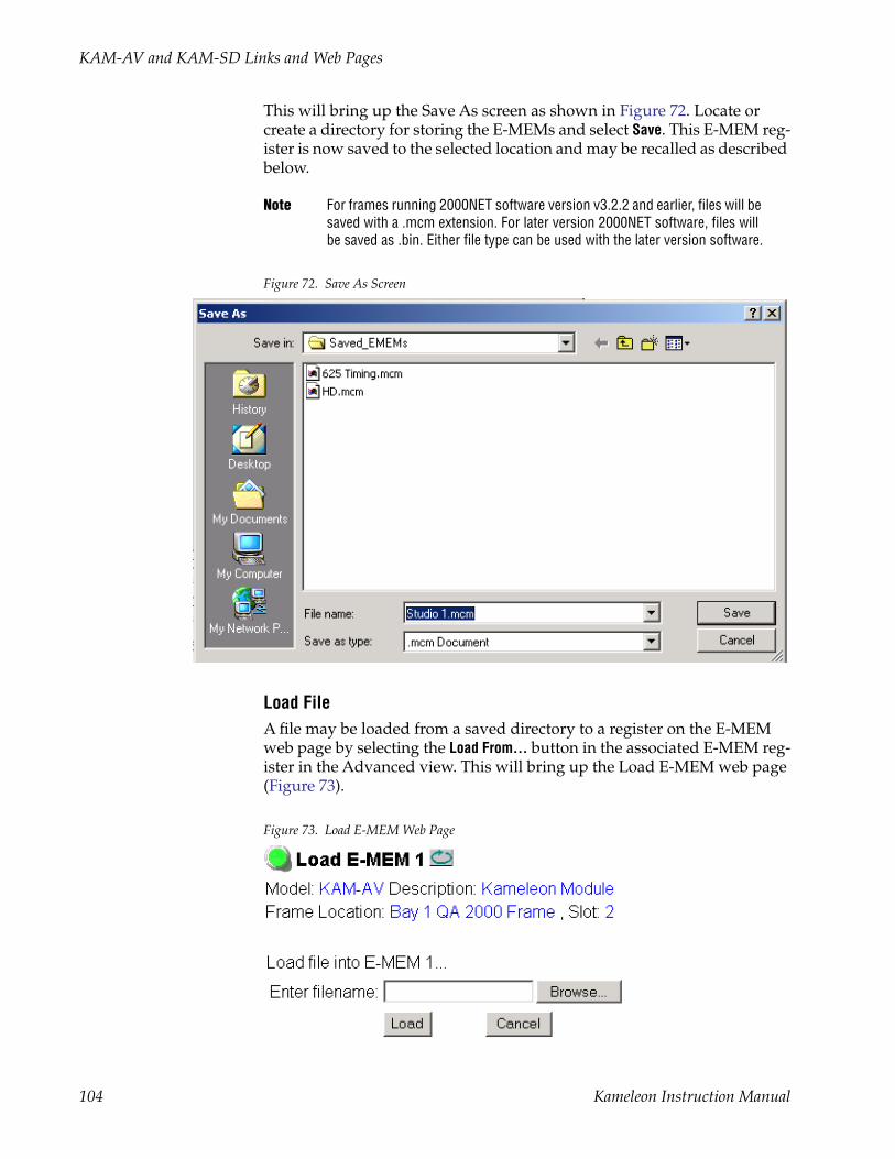
KAM-AV and KAM-SD Links and Web Pages
This will bring up the Save As screen as shown in Figure 72. Locate or create a directory for storing the E-MEMs and select Save. This E-MEM reg-ister is now saved to the selected location and may be recalled as described below.
Note For frames running 2000NET software version v3.2.2 and earlier, files will be saved with a .mcm extension. For later version 2000NET software, files will be saved as .bin. Either file type can be used with the later version software.
Figure 72. Save As Screen
Load FileA file may be loaded from a saved directory to a register on the E-MEM web page by selecting the Load From... button in the associated E-MEM reg-ister in the Advanced view. This will bring up the Load E-MEM web page (Figure 73).
Figure 73. Load E-MEM Web Page
104 Kameleon Instruction Manual
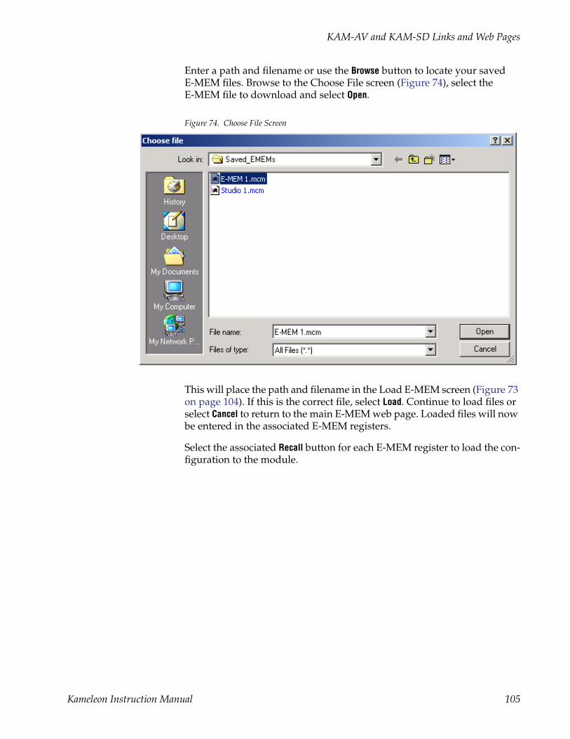
KAM-AV and KAM-SD Links and Web Pages
Enter a path and filename or use the Browse button to locate your saved E-MEM files. Browse to the Choose File screen (Figure 74), select the E-MEM file to download and select Open.
Figure 74. Choose File Screen
This will place the path and filename in the Load E-MEM screen (Figure 73 on page 104). If this is the correct file, select Load. Continue to load files or select Cancel to return to the main E-MEM web page. Loaded files will now be entered in the associated E-MEM registers.
Select the associated Recall button for each E-MEM register to load the con-figuration to the module.
Kameleon Instruction Manual 105

KAM-AV and KAM-SD Links and Web Pages
Slot Configuration Web PageUse the Slot Config web page (Figure 75 on page 107) to:
• Assign an appropriate name to the module slot,
• Assign an Asset Tag identification,
• Enable/disable the Locate Module function,
• Save module configuration and enable slot memory,
• Check SNMP related 2000NET module switch settings, and
• Enable/disable SNMP reporting for the specific Kameleon slot.
Slot IdentificationYou may identify the module by typing a specific name in the Name field. The assigned name is stored on the 2000NET module and travels with the 2000NET module if it is moved to another frame. Select Default to enter the factory default module name.
An asset identification may be entered in the Asset Tag field. This will appear on the module Status web page and in the NetConfig inventory report.
Locate ModuleWhen enabled by selecting the Flash pulldown, the Locate Module function flashes the yellow COMM and CONF LEDs on the front of the module to make it easy to locate in the frame (see Operation Indicator LEDs on page 28).
Slot MemoryThe slot configuration for each media module is automatically saved peri-odically to the 2000NET module in that frame. You may also select the Learn Module Config button at any time to save the current configuration for this slot. The configuration is saved on the 2000NET module. If the 2000NET module is removed or powered down, the stored configurations are not saved.
When the Restore upon Install box has been checked, the current configuration saved to this slot is saved as slot memory. When the current module is removed and another module of the same type is installed, the configura-tion saved to the 2000NET module will be downloaded to the new module. The box must be checked before the current module with the saved config-uration is removed.
Usethislink
106 Kameleon Instruction Manual

KAM-AV and KAM-SD Links and Web Pages
Figure 75. Slot Configuration Web Page
Kameleon Instruction Manual 107
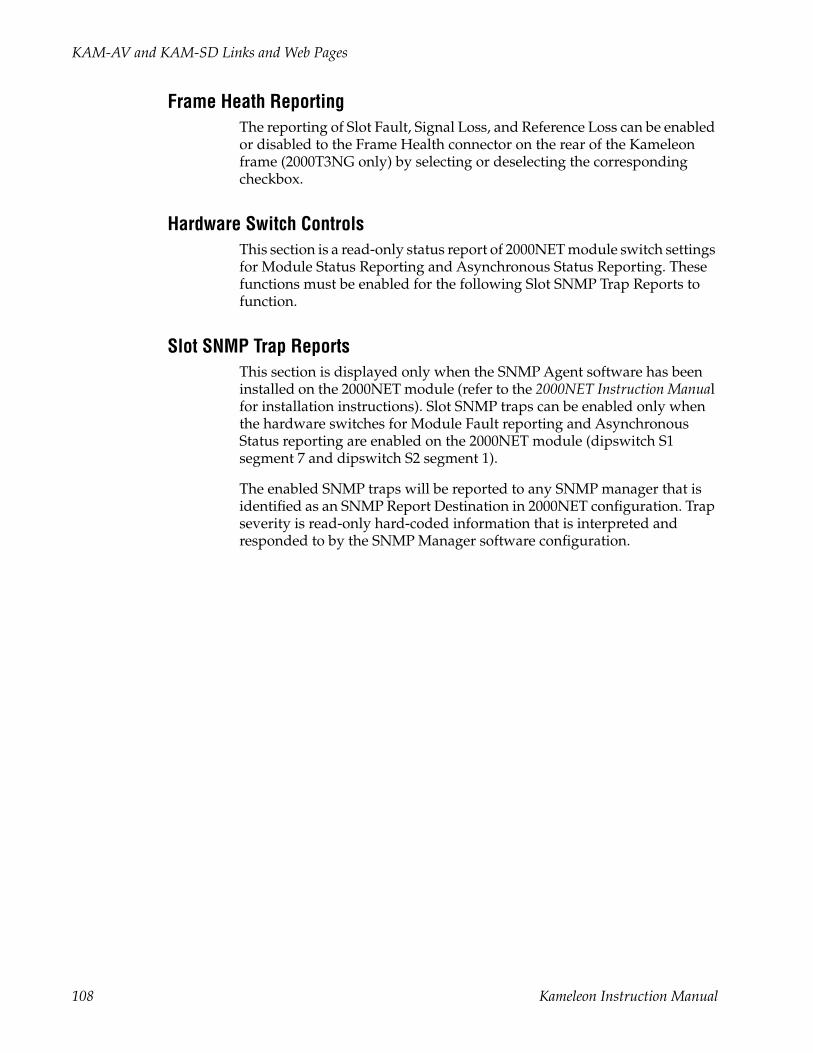
KAM-AV and KAM-SD Links and Web Pages
Frame Heath ReportingThe reporting of Slot Fault, Signal Loss, and Reference Loss can be enabled or disabled to the Frame Health connector on the rear of the Kameleon frame (2000T3NG only) by selecting or deselecting the corresponding checkbox.
Hardware Switch ControlsThis section is a read-only status report of 2000NET module switch settings for Module Status Reporting and Asynchronous Status Reporting. These functions must be enabled for the following Slot SNMP Trap Reports to function.
Slot SNMP Trap ReportsThis section is displayed only when the SNMP Agent software has been installed on the 2000NET module (refer to the 2000NET Instruction Manual for installation instructions). Slot SNMP traps can be enabled only when the hardware switches for Module Fault reporting and Asynchronous Status reporting are enabled on the 2000NET module (dipswitch S1 segment 7 and dipswitch S2 segment 1).
The enabled SNMP traps will be reported to any SNMP manager that is identified as an SNMP Report Destination in 2000NET configuration. Trap severity is read-only hard-coded information that is interpreted and responded to by the SNMP Manager software configuration.
108 Kameleon Instruction Manual

KAM-AV and KAM-SD Links and Web Pages
Software Update Web PageThe Software Update web page (Figure 76) allows you to download new software versions for the module using the FTP server method described in the 2000NET Instruction Manual available on-line.
Software may also be updated using the NetConfig Networking Applica-tion PC option available with Modular and other Grass Valley products as described in the documentation that accompanies the option.
Refer to the latest module Release Notes for complete details on how to obtain and install the latest software for this module.
Figure 76. Software Update Web Page
Usethislink
Kameleon Instruction Manual 109

Specifications
SpecificationsNote Specifications are subject to change without notice.
Table 11. SDI Input/Output Specifications
Parameter Value
SDI Input
Signal type Serial digital video conforming to SMPTE259M 10-bit 4:2:2component digital signal
Input impedance 75 Ω
Connector type 75 Ω BNC on rear module
Input return loss > 15 dB to 270 MHz
Common mode rejection ratio 2 V p-p to 60 Hz
Equalization Up to 250 meters of Belden 1694A
SDI Output
Number of outputs 1
Signal type Serial digital video conforming to SMPTE259M 10-bit 4:2:2 component digital signal
Signal level 800 mV ±10%
Output impedance 75 Ω
Connector type 75 Ω BNC on rear module
DC offset < 0.5 V when terminated into 75 Ω
Output return loss >15 dB up to 270 MHz
Jitter Conforms to SMPTE17.12/002 < 400 ps above 1 KHz
Rise/fall time 700 – 900 ps (20 – 80% amplitude)
EDH error detection and reporting EDH automatically inserted into SD output, conforms to SMPTE recom-mended Practice RP-165
SDI I/O Control Parameters
Vertical blanking processing Line by line blank
Table 12. Composite Input Specifications
Parameter Value
Composite Input
Signal types Composite analog video conforming to:NTSC (525/59.9) SMPTE170MPAL-B/PAL-I (625/50) CCIR 624-4
Level 0.5 V p-p to 2 V p-p, 1 V p-p nominal
Impedance 75 Ω terminating
Signal source 75 Ω BNC on rear module or internal signal
Return loss > 40 dB to 5.75 MHz
Common mode rejection ratio > 60 dB to 60 Hz
HUM peak < 4.5 V p-p
Clamping hum rejection 0 dB
110 Kameleon Instruction Manual

Specifications
Composite In Performance
Sampling 27 MHz (2x oversampling)
Input quantization 12 bits
Overall processing accuracy 10 bits
Luma frequency response ± 0.1 dB to 5.5 MHz
Chroma (R-Y,B-Y) response -1.5 dB @ 1.3 MHz
Group delay error < 5 ns to 5.5 MHz
Chroma/luma delay < 10 ns
Luma non-linearity < 0.15%
K factor (2T) < 0.5%
Line tilt < 0.5%
Field tilt < 0.5%
Differential phase < 1 degree
Differential gain < 1%
Signal/noise ratio (CCIR410 or EIA RS-250B)
> 60 dB to 5.5 MHz
Phasing None
Picture centering error 0.0 ±20 ns non-adjustable
Decoding modes Three-line adaptive with two pre-programmed adaption threshold levels high/low
Blanking start/end SMPTE170M or CCIR624, non-adjustable
Composite In Control
Overall video gain range 44% to 219% in 0.5% steps, 100% default
Black range -21.5% to +22% of luma full-scale in 0.1% steps, 0 default
Hue range -180 to + 179 degrees in 0.1 degree steps, 0 degree default (525 only)
Setup processing in vertical Line by line on/off (525 only)
Vertical blanking processing Line by line blank/notch decode/pass
Table 13. Composite Output Specifications
Parameter Value
Composite output
Number of outputs 1
Signal type Composite analog video conforming to SMPTE170M for NTSC and CCIR624 for PAL-B
Signal level 600 mV to 1.4 V p-p adjustable, 1 V p-p default
Output clamping level 0 VDC ±20 mV
Output impedance 75 Ohm
Connector type 75 Ohm BNC on rear module
Output return loss > 40 dB to 5.5 MHz
Output isolation > 46 dB to 5.5 MHz
Composite Output Performance
Response ± 0.1 dB to 5.0 MHz
Table 12. Composite Input Specifications
Parameter Value
Kameleon Instruction Manual 111

Specifications
Differential phase < 0.5 degrees
Differential gain < 0.9%
Group delay < 10 ns to 5.5 MHz
RMS signal-to-noise > 59 dB to 5.5 MHz
Resolution 10 bits
Accuracy 9.2 bits
Subcarrier jitter < 1 degree when input clock jitter spec is met
Blanking start/end SMPTE170M or CCIR624, non-adjustable
Composite Output Control Parameters
Overall video gain 61% to 138% in 0.5% steps, 100% default
Black range -7.5% to +15% of luma full-scale in 0.1% steps, 0 default
Luma gain 50 – 150% in 1% steps, 100% default
Chroma gain 50 – 150% in 1% steps, 100% default
Hue range ± 22.5 degree 0.5 degree steps, 0 degree default (525 only)
Setup processing in vertical Line by line on/off (525 only)
Vertical blanking processing Line by line blank/unblank
Prefiltering Cross-color & luma reduction 2D filtering on/off
Table 14. AES/EBU Input Specifications
Parameter Value
AES/EBU Input Balanced (AES3-1992) Unbalanced (AES3id 2001)
Common mode range + 10/-10 V, 50 Hz to 20 kHz NA
Differential voltage range 200 mV p-p to 12 V p-p 200 mV p-p to 2 V p-p
Input return loss > 25 dB (100 kHz to 6 MHz) >15 dB (100 kHz to 6 MHz)
Sample rate 32 – 96 kHz 32 – 96 kHz
Performance
Static withstand 5 kV (330 Ω, 150 pF)
Table 15. AES/EBU Output Specifications
Parameter Value
AES/EBU Output Balanced (AES3-1992) Unbalanced (AES3id 2001)
Signal type AES3 1992, 110 Ω AES3id 2001, 75 Ω
Signal level 3 V p-p ±0.2 V @ 110 Ω 1 V p-p ±0.2 V @ 75 Ω
Rise/fall time 5 ns to 30 ns, 110 Ω load 37 ns ± 7 ns, 75 Ω load
Output return loss > 25 dB (100 kHz to 6 MHz) >15 dB (100 kHz to 6 MHz)
Table 13. Composite Output Specifications - (continued)
Parameter Value
112 Kameleon Instruction Manual

Specifications
DC offset < 50 mV <50 mV
Sample rate 48 kHz 48 kHz
Bits/sample 20/24 bits/sample, selectable 20/24 bits/sample, selectable
AES/EBU Performance
Static withstand 5 kV (330 Ω, 150 pF)
Table 16. Audio ADC Specifications
Parameter Value
Analog Input (ADC)
Number of inputs 4 per submodule
Level for full-scale output -2 dB to +28 dBu, adjustable in 0.1 dBu steps
Input impedance > 22 kΩ
Common mode input voltage 20 V maximum
Differential DC 0.25 V maximum
Common mode rejection ratio > 72 dB, 20 Hz to 20 kHz
Connector type Multi-pin (receptacle)
Analog Audio Input Conversion Performance
Signal-to-noise ratio > 102 dB, 20 Hz to 20 kHz> 105 dB, “A” weighted
THD+noise, swept 20 Hz-20 kHz < -75 dB, 20 to 20 kHz, @ +28 dBu
Interchannel crosstalk < -95 dB, 20 Hz to 20 kHz
Intermodulation distortion < -100 dB CCIF two-tone test, 19 & 20 kHz tones
Interchannel gain mismatch 0.1 dB
Frequency response ± 0.1 dB, relative to 1 kHz, 20 Hz to 20 kHz
DC offset ± 1 mV
Emphasis Not selectable
Output resolution 24 bits
Effective number of bits 18
Static withstand 5 kV (330 Ω, 150 pF) any input or output
Table 17. Audio DAC Specifications
Parameter Value
Analog Audio Output (DAC)
Number of outputs 4 per submodule
Signal type -2 dB to +24 dBu, adjustable in 0.1 dBu steps
Output impedance 100 Ω balanced
Drive capability maximum +24 dBu balanced @ 10 KΩ load
Differential DC 0.25 V maximum
Connector type Multi-pin (receptacle)
Table 15. AES/EBU Output Specifications
Parameter Value
Kameleon Instruction Manual 113

Specifications
Analog Audio Output Performance (48 kHz sampling rate)
Signal/noise ratio > 102 dB, 20 Hz to 20 kHz> 105 dB, “A” weighted
THD+noise, swept 20 Hz-20 kHz < -75 dB, 20 Hz to 20 kHz, @ +24 dBu
Interchannel crosstalk < -80 dB, 20 Hz to 20 kHz
Intermodulation distortion < -80 dB CCIF two-tone test, 19 & 20 kHz tones
Interchannel gain mismatch 0.1 dB
Frequency response ± 0.2 dB, relative to 1 kHz, 20 Hz to 20 kHz @ +24 dBu
DC offset ± 50 mV
Output resolution 24 bits
Effective number of bits 18
Static withstand 5 kV (330 Ω, 150 pF) any input or output
Table 18. Frame Sync/Timing Specifications
Parameter Value
Video Frame Sync Timing Control Parameters
Delay adjustment (main) 0 to 1 frame in 37 ns steps
Additional delay, composite out 0 to 151µs in 37 ns steps
Fine phase delay, composite out 0 to 37 ns in 100 steps
Additional delay, SDI out 0 to 151 µs in 37 ns steps
Table 19. Main Video Processing Specifications
Parameter Value
Main Video Frame Processing Control Parameters
Y gain ± 50% in 0.4% steps, 100% default
Y offset ± 3.5% of 100% white in 0.11% steps, 0% default
B-Y gain ± 50% in 0.4% steps, 100% default
B-Y offset ± 3.5% of 100% white in 0.11% steps, 0% default
R-Y gain ± 50% in 0.4% steps, 100% default
R-Y offset ± 3.5% of 100% white in 0.11% steps, 0% default
Color bars on/off
Table 17. Audio DAC Specifications - (continued)
Parameter Value
114 Kameleon Instruction Manual

Specifications
Table 20. Multiplexing/Demultiplexing Specifications
Parameter Value
MUX/DEMUX Performance
Standard SMPTE 272M A, C: Synchronous audio, 48K, 20/24 bits/sample Compatible with buffer sizes down to 48 samples
Pass through Up to 4 groups (frame sync must be in delay mode)
Extract, retime, insert Up to 2 groups
Delete Up to 4 groups
Insert Up to 2 groups
Bits/sample on inserted audio 20/24 bits, selectable
Buffer size 170 samples
DEMUX delay 1.77 ms
MUX delay 1.77 ms
Distribution Evenly distributed, minimum of 3 samples per line, maximum of 4 samples per line except near switching linesSwitch line and nearby lines (lines 4, 5, 6, 317, 318, 319 for 625; 8, 9, 10, 270, 271, 272 for 525) have 0 samples
Table 21. Audio Processing Specifications
Parameter Value
Audio Processing
Number of channels supported 8
Sample Rate Conversion All audio inputs (analog, AES or DEMUX) retimed to output timing ref-erence (either input video or frame reference)
Fixed Delay 0 – 5.2 sec in 20 ms steps, individual setting for each channel
Delay Tracking Delay can be set to automatically track delay through video frame sync with fixed offset
Gain + 6 to -40dB in 0.1dB steps, individual setting for each channel.
Other processing Selectable: Invert; L + R; L-R; -(L-R); 1 kHz; 400 Hz; SilenceIndividual setting for each channel.
Re-pairing Complete flexibility to swap or recombine any input channel with any other
Table 22. Electrical Length Specifications
Parameter Value
Electrical Length
Composite In to Composite Out 2 lines + 10 µs
Composite In to SDI Out 1 line + 10 µs
SDI In to Composite Out 1 line + 16 µs
SDI In to SDI Out 14 µs
SDI In to AES/EBU Out (DMUX) 3.8 ms
SDI In to Analog Audio Out (DMUX) 4.5 ms
Kameleon Instruction Manual 115

Specifications
Analog Audio to Analog Audio 1.9 ms
Analog Audio to AES/EBU 1.2 ms
Analog Audio to SDI Out (MUX) 3.0 ms
AES/EBU to Analog Audio 2.5 ms @ 48 kHz
AES/EBU to AES/EBU 2.0 ms @ 48 kHz
AES/EBU to SDI Out (MUX) 3.8 ms @ 48 kHz
SDI In to SDI Out Audio Delay (DMUX, retime, MUX)
5.6 ms
Table 23. Environmental/Power Specifications
Parameter Value
Environmental
Frame temperature range See Kameleon Frame Manual
Operating humidity range 0 to 90% non-condensing
Non-operating temperature -10 to +70 degrees C
Mechanical
Frame type 2000T1DNG Kameleon Frame or 2000T3NG Kameleon Frame
Power
Consumption KAM-AV – 14 Watts typicalKAM-SD – 11 Watts typicalKAM-ADC-S – 2 Watts typicalKAM-DAC-S – 2 Watts typical
Table 22. Electrical Length Specifications - (continued)
Parameter Value
116 Kameleon Instruction Manual

Service
ServiceThe Kameleon modules make extensive use of surface-mount technology and programmed parts to achieve compact size and adherence to demanding technical specifications. Circuit modules should not be ser-viced in the field except to check and replace fuses.
TroubleshootingIf your module is not operating correctly, proceed as follows:
• Check frame and module power. If power is not present, check the fuse on the +24 V input to the module as illustrated in Figure 77.
• Check for presence and quality of input signals.
• Verify that source equipment is operating correctly.
• Check cable connections.
Figure 77. Location of Module Fuse
Refer to Figure 14 on page 27 for the location of PWR LED and Table 7 on page 28 for proper LED indications.
If the module is still not operating correctly, replace it with a known good spare and return the faulty module to a designated Thomson Grass Valley repair depot. Call your Thomson Grass Valley representative for depot location. Refer to Contacting Grass Valley at the front of this document for the Grass Valley Customer Support Information number.
8173_14
Fuse F1, 2A 125 V
Kameleon Instruction Manual 117

Service
118 Kameleon Instruction Manual

Index
Numerics20/24-bit
audio output 100mode 89
2000GEN 10, 642000NET module
hardware switches 106networking 12requirements 9
24 bitaudio warning 76
3D decodercomb filter 56motion modes 55overview 55summary table 29
3D Motion Threshold controlweb page 55
Aadaptive threshold decoding 54AES Inputs web page 89AES Outputs web page 100analog audio I/O 21Analog Audio Inputs web page 87analog audio outputs
adjustments 98audio pairs 98
Analog Audio Outputs web page 98Apply button 38Apply clips to VBI
web page control 79Asset Tag
assigning 106Status web page 41
audioAES errors 91
clearing 90enable/disable warnings 92
AES outputs 100
AES/EBU inputs 89analog audio inputs
adjustments 88summary table 32
channel lock 95summary table 33
channel pairingcontrols 94summary table 33
channel swapsummary table 33
connections 46conversion submodules 10delay
channel lock 33summary table 33
demultiplexing 30emphasis 89gain
summary table 33web page controls 96
group deletionsummary table 31web page control 74
group replacement 74groups 62multiplexing 74output resolution
web page control 97processing
summary table 34web page controls 96
streams 62, 91synchronizing 95
Audio Channel Pairing web page 94Audio Input Select web page 91Audio Proc web page 96Audio Sync web page 95auto tracking (audio)
summary table 33auto tracking delay 95
Kameleon Instruction Manual 119

Index
Bbalanced audio 46black level (composite out)
summary table 32web page controls 85
blanking 58burst removal
composite output signal 84summary table 32
B-Y gainsummary table 31web page control 72
B-Y offsetsummary table 31web page control 72
Ccabling 20chroma gain (composite out)
summary table 32web page controls 85
chroma gain (saturation)summary table 30web page control 70
chrominance removalcomposite output signal 84
chrominance signal (composite out)summary table 32
clippingapply to VBI 72audio 96summary table 30video 72
Coarse adjust buttonoverview 38
coarse delay (composite out)summary table 32
color codefunctional view page 52
color framingPAL-B video 64
Comb filter 56chroma level 56luma bandwidth 56luma level 56
summary table 29COMM LED 28compatible network software 9Composite In web page 54Composite Out web page 83Composite video in
3D decoder 56Black Level adjustment 54black level setup 54input gain adjustment 54input signal setup (525) 54specifications 110summary table 29
Composite video outadjustments 84specifications 111summary table 32
CONF LED 28configuration
control panel 29overview 39Remote, GUI 29
connector wiring for submodules 21control panel 35cooling 14cross color removal (composite out)
adjustment 84summary table 32
Ddata input 89data lines
black level setup 58configuring 63
delaycomposite output signal 84SDI output signal 86
demultiplexingexample 62
DEMUX web page 62digital audio groups 74documentation online 2
120 Kameleon Instruction Manual

Index
EEDH error reporting 60embedded audio
clearing all HANC data 76deleting 75group deletion 74passing 75
E-MEMAdvanced view 102description 101load file 104save file 103standard view 101web page 101
emphasis 89error reporting
AES audio 92SDI input video 30
extracted audio 62
Ffactory defaults
recall factory defaults 101summary table 29video processor 72
Factory names, recall 101fan 14FAQ database 2fault messages 45fault table 28Fine adjust button
overview 38fine delay (composite out)
adjustment 84summary table 32
Flywheel video decoderenabling 63
frame capacity 14Frame Health Reporting
enabling and disabling 108frame reference
loss of signal reporting 30setting 64summary table 30
frame sync 10, 68
delay 63summary table 30
Frame Sync web page 68freeze modes 68
summary table 30web page controls 68
frequently asked questions 2Functional View web page
KAM-AV module 52KAM-SD module 53
fuse 117
Ggain
composite input video 54composite output video 84
Genlock Reference Module 10graphical user interface (GUI) 40Grass Valley web site 2group replacement 74
HHANC (horizontal ancillary data)
clearing 76summary table 31
Hard/Video Black Clipsummary table 31web page control 72
Hard/Video White Clipsummary table 31web page control 72
hardware requirement 9High Motion decoder
overview 55horizontal timing 68
summary table 30hue (chroma phase)
summary table 31web page control 70
hue (composite out, 525)summary table 32web page control 85
Kameleon Instruction Manual 121

Index
II/O Config web page 46I/O configurations 20, 46inserting modules 14installation
module set 15submodule 18
KKAM-AA-AES-UR Rear module
cabling 25I/O Config web page 49I/O configuration table 26
KAM-AA-R Rear modulecabling 21I/O Config web page 46I/O configuration table 21
KAM-AES-R Rear modulecabling 23I/O Config web page 48I/O configuration table 24
KAM-MIX-R Rear modulecabling 22I/O Config web page 47I/O configuration table 22
LLEDs 28line rate 63locate module 28, 106loss of signal reporting 63
AES audio inputs 92audio 33SNMP traps 108video input 63
Low Motion decoderoverview 55
luma gain (composite out)summary table 32web page controls 85
Mmidplane 19
mixed audio I/O 22Mixed Motion decoder
overview 55module location function 28, 106module slot identification 106multiplexing
24 bit audio warning 76example 77group deletion 74group replacement 77
MUX web page 74
Nnaming module slots 106NetConfig
updating software 109Network Interface Module
version 9networking 12Newton Control Panel
control summary table 29overview 35
notch decode 58NTSC
composite 525 input 54
Oonline documentation 2operational modes 28output levels (analog audio)
summary table 34output resolution
setting 97, 100web page control 97
output sample rate 100output timing source 63
summary table 30outputs
specifications 110
Ppower requirements 116PWR LED 28
122 Kameleon Instruction Manual

Index
Qquickstart 12
Rrear I/O modules 10Refresh button 38removing modules 14repair depot 117R-Y gain
summary table 31web page control 72
R-Y offsetsummary table 31web page control 72
Ssample rate
AES/EBU input 89sample rate conversion
AES/EBU input 33summary table 31
SDI errorsenable/disable warnings 64
SDI In web page 60view selection 30
SDI input errorsenabling/disabling 63summary table 30
SDI video inEDH error reporting 60loss of signal reporting 30
select AES output pairs 100service 117setup 54
composite output signal 84setup (composite out)
summary table 32setup (VBI lines)
summary table 29setup (VBI)
summary table 31web page control 79
signal names 46Slot Config web page 106
slot configurationsaving 106
slot memory 106slot names 106SNMP monitoring 63SNMP trap reports
enabling and disabling 108Soft/Y Black Clip
summary table 31web page control 72
Soft/Y White Clipsummary table 31web page control 72
softwarerequirement 9update 109
software download from web 2specifications
environmental and power 116status indicators
color codes 41meanings 41
Status web page 41streams
audio 62submodule I/O connectors 21submodule installation 16submodules 10synchronizing audio 95
Ttest signals
audio 96color bars (video) 70
timing rangesvideo 68
troubleshooting 117
Uunbalanced audio 46
VVBI configuration
Kameleon Instruction Manual 123
Index
advanced view 63, 66applying clips
summary table 31web page control 81
blank VBI linessummary table 31web page control 81
blanking 79clipping, summary table 31remove setup 79reserving lines for data 66setup enable/disable 79summary table 29, 30
VBI Decode web page 58VBI Encode web page 79VBI encoding
summary table 31web page controls 79
VBI SDI web page 81vertical blanking interval (VBI) 63vertical timing 68
summary table 30video
format 63input select 63line rate 63loss of signal reporting 63selectin input format 63timing ranges 68
video gain (composite out)summary table 32
Video Gain Locksummary table 30web page 72
Video Input Select web page 63video processing 70
clipping controls 72summary table 30web page controls 70
Wwarning messages 45web browser
overview 36web site
documentation 2
FAQ database 2Grass Valley 2software download 2
YY Gain (contrast)
summary table 30web page control 70
Y Offset (brightness)summary table 31web page control 70
124 Kameleon Instruction Manual