Embed Size (px)
Citation preview
KaBOOM- Ka Band Objects: Observation and Monitoring
Dr. Barry Geldzahler
NASA Headquarters, Washington DC
Marc Seibert and Michael Miller
NASA Kennedy Space Center, Cape Canaveral, Florida
Dr. Victor Vilnrotter and Philip Tsao
Jet Propulsion Laboratory, Pasadena CA
ABSTRACT
With the successful completion (Sept 2010) of a field demonstration of uplink arraying at 8 GHz (X-band) using
real-time atmospheric compensation enabled by phase transfer rather than time transfer techniques, NASA is
pursuing a similar demonstration of the capability at 30-31 GHz (Ka band). Such a demonstration would then enable
NASA to establish [a] a high power, high resolution, 24/7 availability radar system for characterizing observations
of Near Earth Objects, determining the statistics of small [≤10cm] orbital debris, [b] to incorporate the capability
into its space communication and navigation tracking stations for emergency spacecraft commanding in the Ka band
era which NASA is entering, and [c] to field capabilities of interest to other US government agencies. We describe
a project of Evolutionary Steps Leading to Revolutionary Increases in Capability and Capacity.
1.0 INTRODUCTION
NASA has embarked on a path to implement a high power, higher resolution radar system to better track and
characterize near Earth objects [NEO’s] and orbital debris. We are advancing an X/Ka band system to supplement
the S-band radar at Arecibo, Puerto Rico and the X-band radar at NASA’s Goldstone tracking complex in
California. The three facilities will complement each other in that different wavelengths have different resolutions
and penetration depths. The X/Ka band radar system also has applications for cost effective space situational
awareness. This work describes our path toward demonstrating Ka band coherent uplink arraying with real-time
atmospheric compensation using three 12m diameter antennas at the Kennedy Space Center. Coherent uplink
arraying has been successfully demonstrated by three NASA groups: at X band Ku bands, with and without
atmospheric compensation, and by sending commands to and receiving telemetry from GEO and deep space
satellites.
KaBOOM is a Ka band coherent uplink arraying proof of concept demonstration being undertaken to allow
decision to be made for implementing a National Radar Facility [large scale arrays(s)]:
High power, high resolution radar system
Space Situational Awareness
24/7 availability for NEO and orbital debris tracking and characterization
High resolution mapping of water in discrete locations on the moon
Map out radar stealth zones on Mars- help define ―no drive‖ zones for future rovers to avoid the Spirit problem
Solar sailing propulsion capability
2.0 THE NEED FOR UPLINK ARRAYING
NASA has several major needs for uplink arraying: (1) planetary defense- tracking and characterization (size, shape,
spin, porosity) of near Earth objects (NEOs), (2) Improved detection/tracking of small (≤1-10cm) orbital debris
particles, (3) rapidly available high power emergency uplink capability for spacecraft emergencies, (4) radio science
experiments (tomography of planetary atmospheres, general relativity tests, mass determinations, occultations,
surface scattering, etc). The NASA Authorization Act of 2008 directs NASA to catalog 90% of NEOs > 140m in
size. The Goldstone radar on the 70m antenna is available only 2-3% of the time due to spacecraft tracking
obligations and is further limited by the high power density of the beam since the transmitter is 450 kW.
Tracking of orbital debris particles less than 10cm is size is difficult. Where high resolution is possible, the antenna
beam is too small for accurate tracking; statistics of small particles are obtained, however. In those facilities where
particle tracking is possible, the resolution is lacking.
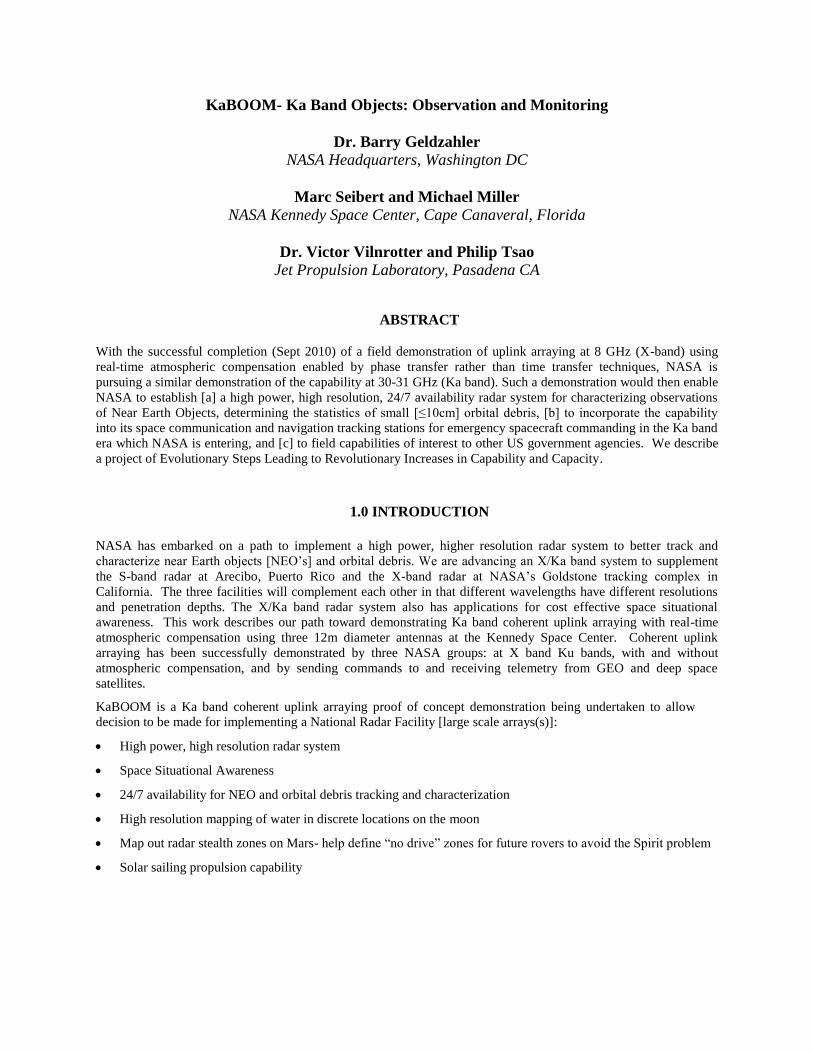
Fig 1. Relative sizes of asteroid Itokawa and the International Space Station. Note the boulders on the asteroid. For
robotic and crewed missions to asteroids, NASA will need to know the surface structure - such as the boulders in the
box - so as to ensure the safety of the landing spacecraft and its inhabitants.
It is interesting to note that uplink arraying offers an opportunity to get high EIRP (effective isotropic radiated
power) from relatively lower power transmitters because the uplink power, for identical transmitters and antennas, is
proportional to N2, where N is the number of antennas in the array. Figure 2 demonstrates this effect for data taken
of the planet Venus with two of the 34m antennas at Goldstone. Figure 2a shows the radar image for a single 34m
antenna. Figure 2b shows the radar image, with a 6 dB gain (factor of 4) when two 34m dishes were coherently
linked.
range
Doppler
range
Doppler
Fig 2. Doppler-delay images of Venus, taken on 2010 DOY-297, Goldstone Solar System Radar processing: a)
single 34m antenna illumination; b) 2-34m antenna phased-array illumination, showing greatly improved image
quality.
a
(b) (a)

3.0 ADVANTAGES OF A MULTIPURPOSE FACILITY EMPLOYING UPLINK
ARRAYING TECHNIQUES
The array is a more reliable resource than a single dish. If the 70m is down for any reason, so too is the radar
facility. The same is true for the high power klystron tubes used for the radar. However, with an array, if any
given antenna is taken out for maintenance or is in an anomalous condition, little performance is lost. For
example, losing a single antenna out of 25 would be a loss of only 2% of the array downlink capability and only
1% of the uplink capability. Hence, availability of the array is more assured and robust to operational ―down
time‖ or element failures.
Virtually 24/7 availability. Whereas radar observations on the DSN 70m antenna comprise < 3% of the
available antenna time, on a NEO-focused purpose array, some 25-30 times more antenna time could be
available and thus 25-30 times the number of sources can be observed in a given year. This will dramatically
help NASA reach the goal of tracking and characterizing 90% of NEOs ≥140m by 2020.
Spectrum management is not an issue with the array. Since the high power, coherently combined beam forms
~200 km above the earth, the FAA EIRP limit will not be violated obviating the need for a time-consuming
coordination among a large number of Agencies.
The angular resolution of the proposed array is 4 times better than that of the 70m antenna at Goldstone. With
antenna spacings of 60m, an effective diameter of ~300m can be achieved- imagine a 5x5 antenna array.
Increased angular resolution can help characterize NEOs in unprecedented detail. Bistatic and multistatic modes
offer even finer resolution.
Scalability. If still higher resolution or greater sensitivity is desired, additional antenna elements can be added.
At roughly $1M per antenna element, increased capability can be added at a low cost.
Extensibility to Ka band. This would be unique to NASA and provide 16 times the angular resolution of the
70m radar system as well as significantly improved range and range-rate measurement.
Radio science experiments are usually conducted by transmitting signals from the spacecraft past/through the
target of interest to the ground. However, spacecraft transmitters, ~20W, limit the signal to noise ratio and
hence the science results. Using a high power uplink from the ground to the target to the spacecraft and then
downlinking the data via telemetry (ala New Horizons) can increase the S/N by ≥ 1000. Science using
traditional ―downlink‖ measurement techniques will also be improved due to the higher sensitivity of the array.
4.0 UPLINK ARRAYING WITH REAL-TIME ATMOSPHERIC COMPENSATION
DEMONSTRATED
NASA and the Martin/Minear: local closed-loop phase control calibration method. This demo was done at X-band
using 3 low cost 12m antennas. Modulated (2MHz bandwidth BPSK, and QPSK, 2Mbps rate ½ Viterbi) signals
were sent to geostationary satellites. G. Patrick Martin and Kathy Minear demonstrated conclusively that coherently
combined uplink array signals can be achieved using a model-based uplink arraying method that does not require
external calibration targets due to a continually self-calibrating circuit control thereby yielding instant availability of
the system. Furthermore, they demonstrated that if there is a reference source such as a beacon on the uplink target
satellite or a background celestial source (e.g.- a quasar), then the system can compensate in real time for
atmospheric fluctuations- providing that both the target source and reference source are in the primary beam of each
antenna of the array: the radio frequency analog of adaptive optics.. This group too demonstrated the theoretical
benefits in EIRP for uplink combining, namely, a 6 dB power enhancement for a two antenna element system and a
9.6 dB for an array of 3 antennas. Also, demonstrated were the theoretical benefits in G/T for downlink combining.
The major downside to this demonstration is that NASA was not given access to the algorithms so we have not been
able to verify whether the techniques demonstrated represent simply a point solution or whether they are applicable
in general.
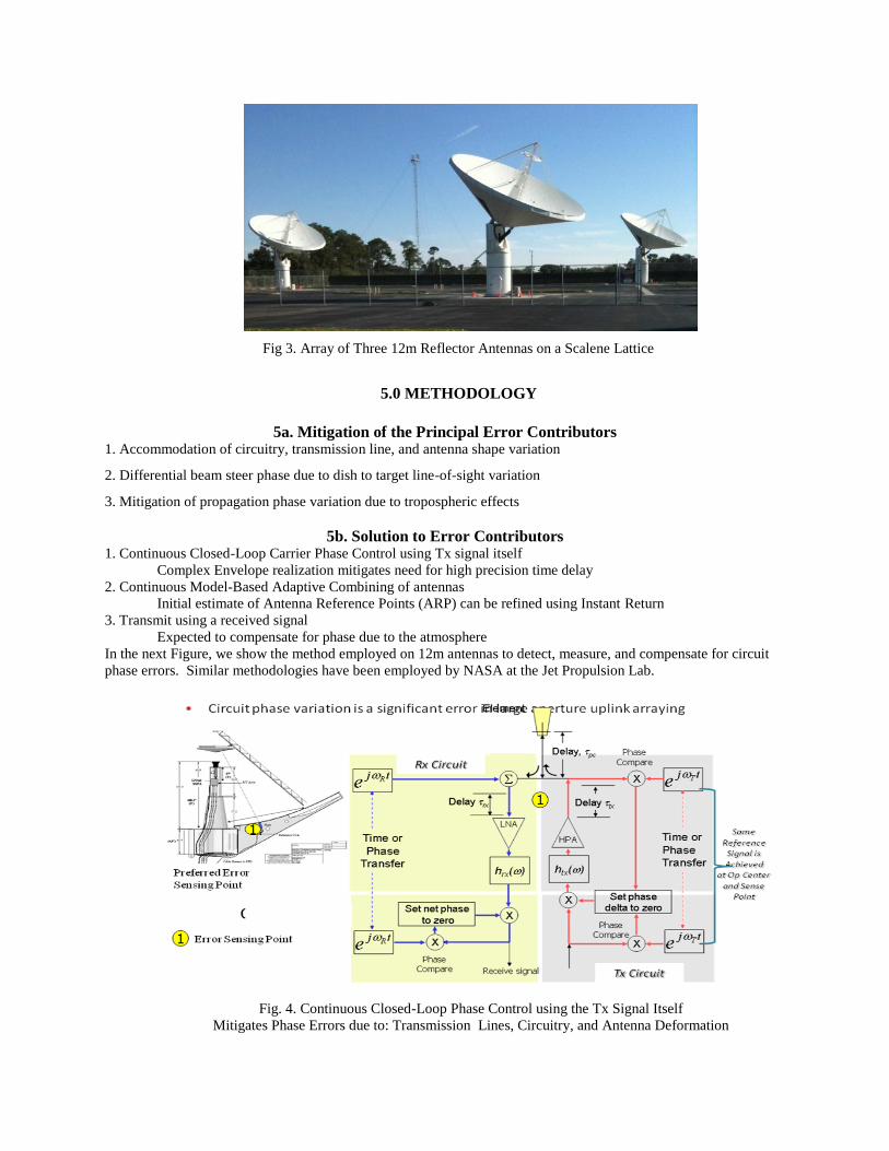
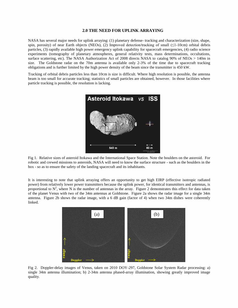
Fig 3. Array of Three 12m Reflector Antennas on a Scalene Lattice
5.0 METHODOLOGY
5a. Mitigation of the Principal Error Contributors
1. Accommodation of circuitry, transmission line, and antenna shape variation
2. Differential beam steer phase due to dish to target line-of-sight variation
3. Mitigation of propagation phase variation due to tropospheric effects
5b. Solution to Error Contributors 1. Continuous Closed-Loop Carrier Phase Control using Tx signal itself
Complex Envelope realization mitigates need for high precision time delay
2. Continuous Model-Based Adaptive Combining of antennas
Initial estimate of Antenna Reference Points (ARP) can be refined using Instant Return
3. Transmit using a received signal
Expected to compensate for phase due to the atmosphere
In the next Figure, we show the method employed on 12m antennas to detect, measure, and compensate for circuit
phase errors. Similar methodologies have been employed by NASA at the Jet Propulsion Lab.
Fig. 4. Continuous Closed-Loop Phase Control using the Tx Signal Itself
Mitigates Phase Errors due to: Transmission Lines, Circuitry, and Antenna Deformation

6.0 RESULTS: CLOSED LOOP CIRCUIT CONTROL EXPERIMENT
In order to achieve a coherent beam for uplink, the phase errors around the circuit should be as small as possible. In
the case of the demonstration in Florida, our goal was to achieve a peak-to-peak phase variation of no more than 10o
and an rms phase variation of no more than 3o. After accounting for some less than optimum hardware, both goals
were achieved and indeed surpassed. Figure 4 shows the phase stability of the closed loop system over an 83+ hour
run.
Fig. 5. Results for Closed Loop Circuit Control using Transmit Error Detection Assemblies.
7.0 ATMOSPHERIC FLUCTUATION PHASE ERROR CORRECTION:
RF ADAPTIVE OPTICS
The tropospheric contribution to phase errors can be significant and are certainly unpredictable as evidenced by
water vapor radiometer measurements. However, there is no apparent linkage between meteorological data and the
observed phase fluctuations. Thus, ground-level measurements are not accurate indicators of what is occurring
higher in the atmosphere. Developing an all encompassing, universal model to predict the phase stability of a
particular site would be extremely difficult. Furthermore, if the longest baseline of the array is even a few
kilometers in extent, different weather conditions above individual array elements would make precise modeling of
atmospheric phase fluctuations of the array as a whole an extraordinary challenge.
A simpler solution is to develop a real-time atmospheric compensation algorithm just as the optical astronomers do
using a sodium laser to get an artificial ―star‖ in the telescope field of view simultaneously with the object of
interest. The algorithm developed for the closed loop uplink arraying demo, the RF analog of the well known
adaptive optics methodology, was successfully used to mitigate in real-time the varying atmospheric fluctuations.
The algorithm handles the general case where each dish-to-target path may be looking at different columns of
atmosphere due to the wide spacing of the elements.
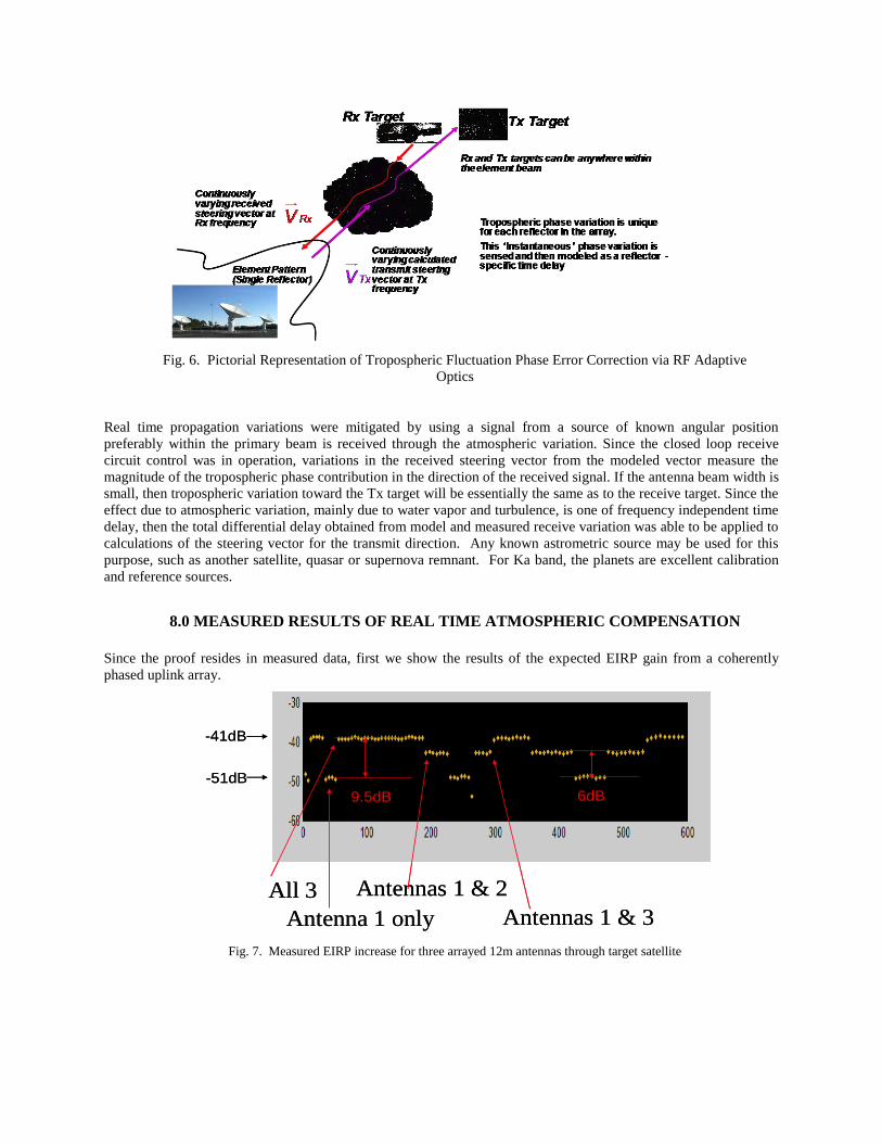
Fig. 6. Pictorial Representation of Tropospheric Fluctuation Phase Error Correction via RF Adaptive
Optics
Real time propagation variations were mitigated by using a signal from a source of known angular position
preferably within the primary beam is received through the atmospheric variation. Since the closed loop receive
circuit control was in operation, variations in the received steering vector from the modeled vector measure the
magnitude of the tropospheric phase contribution in the direction of the received signal. If the antenna beam width is
small, then tropospheric variation toward the Tx target will be essentially the same as to the receive target. Since the
effect due to atmospheric variation, mainly due to water vapor and turbulence, is one of frequency independent time
delay, then the total differential delay obtained from model and measured receive variation was able to be applied to
calculations of the steering vector for the transmit direction. Any known astrometric source may be used for this
purpose, such as another satellite, quasar or supernova remnant. For Ka band, the planets are excellent calibration
and reference sources.
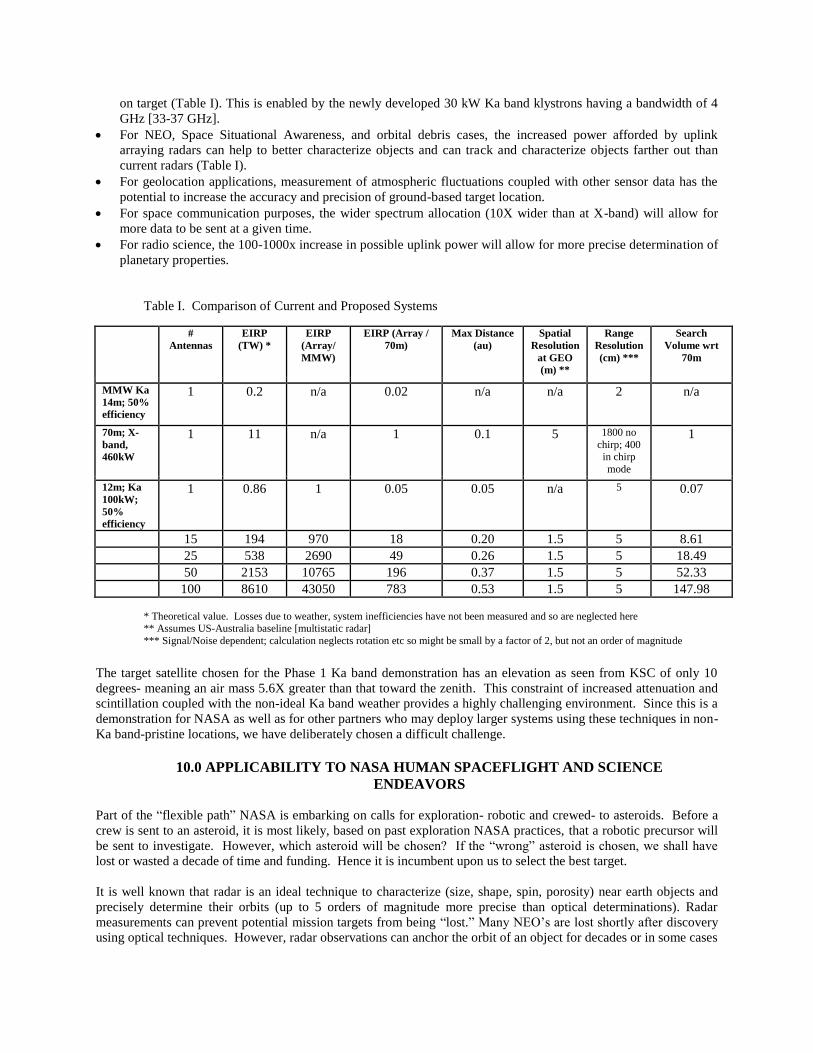
8.0 MEASURED RESULTS OF REAL TIME ATMOSPHERIC COMPENSATION
Since the proof resides in measured data, first we show the results of the expected EIRP gain from a coherently
phased uplink array.
All 3
Antenna 1 only
Antennas 1 & 2
Antennas 1 & 3
6dB
-41dB
-51dB
9.5dB
All 3
Antenna 1 only
Antennas 1 & 2
Antennas 1 & 3
6dB
-41dB
-51dB
9.5dB
Fig. 7. Measured EIRP increase for three arrayed 12m antennas through target satellite

We were not satisfied testing the algorithms and demonstrating coherent uplink arraying in clear, relatively dry (for
Florida!) air. Fortunately, Tropical Depression 16, later upgraded to Tropical Storm Nicole, provided a marvelous
opportunity to excel.
Fig. 8. Conditions of a robust test of real-time atmospheric fluctuation compensation coherent uplink arraying
Under these conditions, Fig. 9 shows the phase fluctuations with and without the real-time atmospheric fluctuation
algorithm noted in the figure as ―instant return.‖ Note that the peak to peak variations are almost an order of
magnitude less using the correction algorithm than without. Even on a ―good‖ day in coastal central Florida, the
algorithm increased the coherent signal by 0.5 dB on the single, limited test we carried out.
Instant Return ONInstant Return OFF
Difference between measured and modeled Rx SV (propagation error)
Modem output (connected to Rx optimum beam)
(2.2dB variation due to uplink with IR=OFF, < ±0.3 dB with IR ON)
Time, sec
Single Antenna Rx (spectrum analyzer)
Fig. 9. Demonstration of ~ order of magnitude decrease in phase fluctuations using RF using the compensation
algorithm

With the demonstration of real-time atmospheric fluctuation compensation, we have almost closed the chapter on
uplink arraying demos at X-band.
9.0 NEXT STEP: KaBOOM: Ka BAND OBJECTS OBSERVATION AND
MONITORING
Fig. 10. KaBOOM Test Bed Setup at Kennedy Space Center
Going beyond X-band for NASA involves Ka band tracking capabilities. Although the demonstration of coherent
uplink arraying at Ku band has been successful and gives us encouragement that such techniques will be successful
at Ka band, we have no data to bear out that hypothesis. Furthermore, we have not yet shown how to make uplink
arraying reliable in an operational sense because we have not previously had the resources to undertake that aspect.
In Phase 1, building on the previous three-antenna element interferometer testbed to demonstrate the N2 , where N is
the number of antennas in the array, the antennas have been moved to a government facility: NASA’s Kennedy
Space Center to ensure security and lower life cycle costs. The new three-antenna element interferometer testbed
will re-validate previously obtained data, reestablishing the testbed overall baseline performance incorporating
lessons learned from the initial instantiation. Thereafter, we intend to demonstrate coherent uplink arraying with
real-time atmospheric fluctuation correction at Ka band 30-31 GHz.
In Phase 2, given successful performance and passing of NASA and our partner’s funding decision gates, we shall
construct a larger, multi-element array to increase capability. The Table below shows the potential advantages. It is
evident that even with a modest number of antennas (15), there is the possibility of a 100% increase in maximum
imaging distance over the current 70m capability and the ability to track objects over a volume more than 8.6 times
larger than is current possible. Even a modest system of antennas can provide a substantially greater uplink power
than is current available at Ka band. However, this assumes coherent uplink arraying at Ka-band can be
accomplished. Phase 1 is designed to demonstrate this capability and its limitations; i.e.- where does Ka band uplink
arraying break down or become ineffective.
The advantages of operations at Ka band are enormous:
For radar applications, an increased spectral bandwidth allocation of 2.6 GHz (vs. 100 MHz at X-band-
Goldstone radar) thereby leading to a dramatic increase in spatial and range resolutions as well as more power
on target (Table I). This is enabled by the newly developed 30 kW Ka band klystrons having a bandwidth of 4
GHz [33-37 GHz].
For NEO, Space Situational Awareness, and orbital debris cases, the increased power afforded by uplink
arraying radars can help to better characterize objects and can track and characterize objects farther out than
current radars (Table I).
For geolocation applications, measurement of atmospheric fluctuations coupled with other sensor data has the
potential to increase the accuracy and precision of ground-based target location.
For space communication purposes, the wider spectrum allocation (10X wider than at X-band) will allow for
more data to be sent at a given time.
For radio science, the 100-1000x increase in possible uplink power will allow for more precise determination of
planetary properties.
Table I. Comparison of Current and Proposed Systems
#
Antennas
EIRP
(TW) *
EIRP
(Array/
MMW)
EIRP (Array /
70m)
Max Distance
(au)
Spatial
Resolution
at GEO
(m) **
Range
Resolution
(cm) ***
Search
Volume wrt
70m
MMW Ka
14m; 50%
efficiency
1 0.2 n/a 0.02 n/a n/a 2 n/a
70m; X-
band,
460kW
1 11 n/a 1 0.1 5 1800 no
chirp; 400 in chirp
mode
1
12m; Ka
100kW;
50%
efficiency
1 0.86 1 0.05 0.05 n/a 5 0.07
15 194 970 18 0.20 1.5 5 8.61 25 538 2690 49 0.26 1.5 5 18.49 50 2153 10765 196 0.37 1.5 5 52.33 100 8610 43050 783 0.53 1.5 5 147.98
* Theoretical value. Losses due to weather, system inefficiencies have not been measured and so are neglected here ** Assumes US-Australia baseline [multistatic radar]
*** Signal/Noise dependent; calculation neglects rotation etc so might be small by a factor of 2, but not an order of magnitude
The target satellite chosen for the Phase 1 Ka band demonstration has an elevation as seen from KSC of only 10
degrees- meaning an air mass 5.6X greater than that toward the zenith. This constraint of increased attenuation and
scintillation coupled with the non-ideal Ka band weather provides a highly challenging environment. Since this is a
demonstration for NASA as well as for other partners who may deploy larger systems using these techniques in non-
Ka band-pristine locations, we have deliberately chosen a difficult challenge.
10.0 APPLICABILITY TO NASA HUMAN SPACEFLIGHT AND SCIENCE
ENDEAVORS
Part of the ―flexible path‖ NASA is embarking on calls for exploration- robotic and crewed- to asteroids. Before a
crew is sent to an asteroid, it is most likely, based on past exploration NASA practices, that a robotic precursor will
be sent to investigate. However, which asteroid will be chosen? If the ―wrong‖ asteroid is chosen, we shall have
lost or wasted a decade of time and funding. Hence it is incumbent upon us to select the best target.
It is well known that radar is an ideal technique to characterize (size, shape, spin, porosity) near earth objects and
precisely determine their orbits (up to 5 orders of magnitude more precise than optical determinations). Radar
measurements can prevent potential mission targets from being ―lost.‖ Many NEO’s are lost shortly after discovery
using optical techniques. However, radar observations can anchor the orbit of an object for decades or in some cases
centuries. Furthermore, higher powers and thus farther distances can be achieved with an arrayed system thereby (a)
expanding the search volume for NEO’s (a factor of ~150 for an array of 100 antennas), and (b) through
characterization, narrow the potential target list thereby reducing the risk of sending a robotic precursor mission to
the ―wrong‖ asteroid.
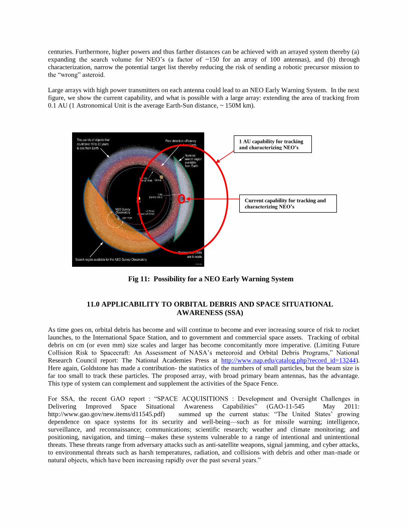
Large arrays with high power transmitters on each antenna could lead to an NEO Early Warning System. In the next
figure, we show the current capability, and what is possible with a large array: extending the area of tracking from
0.1 AU (1 Astronomical Unit is the average Earth-Sun distance, ~ 150M km).
Fig 11: Possibility for a NEO Early Warning System
11.0 APPLICABILITY TO ORBITAL DEBRIS AND SPACE SITUATIONAL
AWARENESS (SSA)
As time goes on, orbital debris has become and will continue to become and ever increasing source of risk to rocket
launches, to the International Space Station, and to government and commercial space assets. Tracking of orbital
debris on cm (or even mm) size scales and larger has become concomitantly more imperative. (Limiting Future
Collision Risk to Spacecraft: An Assessment of NASA’s meteoroid and Orbital Debris Programs,‖ National
Research Council report: The National Academies Press at http://www.nap.edu/catalog.php?record_id=13244).
Here again, Goldstone has made a contribution- the statistics of the numbers of small particles, but the beam size is
far too small to track these particles. The proposed array, with broad primary beam antennas, has the advantage.
This type of system can complement and supplement the activities of the Space Fence.
For SSA, the recent GAO report : ―SPACE ACQUISITIONS : Development and Oversight Challenges in
Delivering Improved Space Situational Awareness Capabilities‖ (GAO-11-545 May 2011:
http://www.gao.gov/new.items/d11545.pdf) summed up the current status: ―The United States’ growing
dependence on space systems for its security and well-being—such as for missile warning; intelligence,
surveillance, and reconnaissance; communications; scientific research; weather and climate monitoring; and
positioning, navigation, and timing—makes these systems vulnerable to a range of intentional and unintentional
threats. These threats range from adversary attacks such as anti-satellite weapons, signal jamming, and cyber attacks,
to environmental threats such as harsh temperatures, radiation, and collisions with debris and other man-made or
natural objects, which have been increasing rapidly over the past several years.‖
1 AU capability for tracking
and characterizing NEO’s
Current capability for tracking and
characterizing NEO’s
A Ka band system using coherent uplink arraying techniques and bistatic and multistatic radars can meet and
probably exceed the goals or, at the very least, compliment a 90 GHz system. Specifically, at Ka-band range
resolution of 5 cm and a spatial resolution (using a US-Australia baseline) of ~ 7 cm can be achieved.
The first demonstration of using coherent uplink arraying has been undertaken at the Jet Propulsion Lab
(Vilnrotter and Tsao) using two 34m beam wave guide antennas at X-band. Precise calibration of Array Radar
antenna phase required, and the phase calibration can be accomplished via the ―Moon-Bounce‖ method. In
addition, closed-loop phase control is required to maintain phase calibration since temperature variations and
equipment instabilities degrade coherence. The proposed array radar approach provides simultaneous
projection of OD velocity vectors onto three independent baselines, thus enabling trajectory determination
from a single Array Radar observation!
In brief, three 34m BWG antennas with 20 kW transmitters at 7.18 GHz are available. The array spans ~ 500
meters with antenna null-to-null beamwidths ~ 170 mdegs and spaceings: DSS-24 – DSS-25 baseline ~ 23
mdegs and DSS-24 – DSS-26 baseline ~ 15 mdegs. For a single antenna: EIRP of 34m antenna, 20 kW
transmitter; two antenna array: peak EIRP of 34m antenna, 80 kW transmitter; three antenna array: peak EIRP
of 34m antenna, 180 kW transmitter. CAVEAT: Simultaneous multi-frequency/multi-baseline operation
remains to be shown. This would enable processing of simultaneous echoes from different baselines.
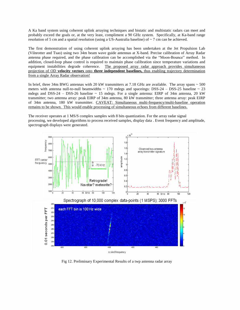
The receiver operates at 1 MS/S complex samples with 8 bits quantization. For the array radar signal
processing, we developed algorithms to process received samples, display data . Event frequency and amplitude,
spectrograph displays were generated.
Fig 12. Preliminary Experimental Results of a twp antenna radar array
12.0 APPLICABILITY TO MAPPING OUT “NO DRIVE” ZONES ON MARS
A radar stealth region 2000 x ~ 300 km was discovered on Mars (Muhleman et al. 1993). It was dubbed a stealth
region because there were virtually no radar reflections from the area. The best postulate for the stealth property is
that the soil has a density of 0.5 gm/cc thus inhibiting reflections. It is believed that the Mars rover Spirit got stuck
in such a ―sandy‖ constituency- away from the stealth region (McCuistion, private communication 2012). If could
map the entire planet and the locations of such regions- e.g., ―no drive‖ zones, we might save or increase the useful
lifetimes of multibillion dollar assets.
Once we have established that Ka band uplink arraying is possible, the next step is to establish a large array with
high power Ka band transmitters. Using arrays with radio astronomy resolution techniques on a US-Australia
baseline at Ka band would provide a ground resolution of 50 km. Useless for attaining our goal. Using radio
astrometry techniques where we can measure to 1/100 of a beam or better, we might expect to get resolutions of 0.5
km. Interesting, but the fundamental limitation is the diameter of the Earth. With 2- 50kW transmitters on a feasible
number of antennas, we can use the array in a SAR mode and let baseline be determined by the motion of the
planets. Preliminary calculations show that at Mars closest approach to Earth, about 9 * 107 km, a ground resolution
of 10m can be obtained! The problem of 1/r4 losses from radar observations still exists, though. If, however, NASA
puts an orbiter around Mars with Ka band capability, a high power signal from Earth could reflect off the planet and
be captured on the spacecraft thereby changing a 1/r4 diminution to merely a 1/r
2 effect.
13.0 APPLICATION TO SOLAR SAILING
Here, a microwave beam will strike a solar sail delivering electromagnetic pressure. This is a natural extension of
solar sailing in that the microwave beam assists the sun (Benford and Benford 2003). A qualitative study of how
much mass could be delivered to Mars at closest approach was undertaken in 2004, and provided intriguing results
(Benford and Benford 2004). NASA is exploring a proof of concept demonstration as a prelude to a large scale,
high power uplink array as one of the tools in the human space exploration tool kit
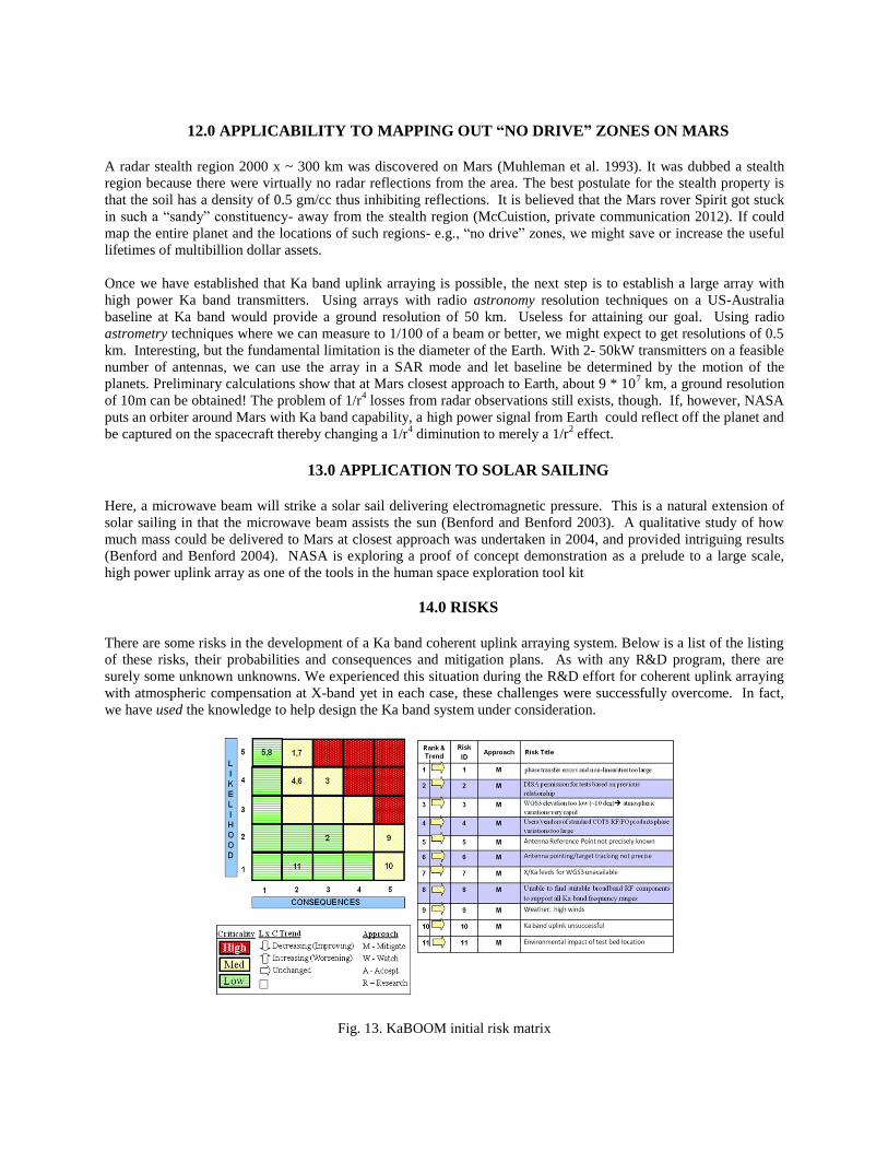
14.0 RISKS
There are some risks in the development of a Ka band coherent uplink arraying system. Below is a list of the listing
of these risks, their probabilities and consequences and mitigation plans. As with any R&D program, there are
surely some unknown unknowns. We experienced this situation during the R&D effort for coherent uplink arraying
with atmospheric compensation at X-band yet in each case, these challenges were successfully overcome. In fact,
we have used the knowledge to help design the Ka band system under consideration.
Fig. 13. KaBOOM initial risk matrix

15.0 CONCLUSIONS
We have the funding in place for a demonstration of uplink arraying at Ka band with real-time compensation for
atmospheric fluctuations. We shall start in a space communications mode and then demonstrate Ka band radar
capabilities. We expect to begin the implementation in summer of 2012. Additionally, a skunk works project team
has been established: (1) minimal formal management- all team members will manage the project together; (2) a
top-drawer technical team. Finally, it is gratifying that all the hard work and accomplishments over the last decade
on various aspects of uplink arraying has garnered broad support with NASA and with our mission partners.
16.0 ACKNOWLEDGEMENTS
It is a pleasure to thank Pete Aragona, Jason Crusan, Lindley Johnson, Richard McGinnis, Bill Marinelli, G. Patrick
Martin, Michael Miller, Kathleen Minear, Wade Minear, Chris Moore, and Marc Seibert, for their guidance and
encouragement regarding the demos. The author also is appreciative of NASA management at Headquarters at the
Division, Directorate, and Agency levels for allowing these demonstrations to be undertaken.
REFERENCES
Benford, G. and Benford, J. 2003, The Planetary Report, January/February
Benford, G. and Benford, J. 2004, private communication.
G. Patrick Martin, Kathy Minear, Barry J. Geldzahler, and Jason Soloff ―Large Reflector Uplink Arraying‖
SpaceOps 2010 Conference ―Delivering on the Dream‖ 25 - 30 April 2010, Huntsville, Alabama AIAA 2010-2175.
Geldzahler, B., 2011, ―Coherent Uplink Arraying Techniques for Next Generation Space Communications and
Planetary Radar Systems,‖ SPIE Defense, Security + Sensing
Geldzahler, B., 2011, ―Coherent Uplink Arraying: A Self-Calibrating, Nearly Stand-Alone System, ‖ Military
Sensing Symposium/Broad Area Maritime Surveillance
McCuistion, private communication 2012.
Muhleman et al. 1993, Science , 253, 1508.
Vilnrotter, V. and Tsao, P. 2012, in preparation.