Embed Size (px)
Citation preview
78: 8–4 (2016) 133–145 | www.jurnalteknologi.utm.my | eISSN 2180–3722 |
Jurnal
Teknologi
Review Paper
OPTIMIZING FLAME SYNTHESIS OF CARBON NANOTUBES:
EXPERIMENTAL AND MODELLING PERSPECTIVES
Muhammad Thalhah Zainal, Mohd Fairus Mohd Yasin*, Mazlan
Abdul Wahid
High Speed Reacting Flow (HiREF) Laboratory, Universiti Teknologi
Malaysia, 81310 UTM Johor Bahru, Johor, Malaysia
Article history
Received
1 January 2016
Received in revised form
18 May 2016
Accepted
15 June 2016
*Corresponding author
Abstract
Synthesis of carbon nanotubes in flames has become highly attractive due to its rapid, inexpensive, and simple method of
production. The study of flame synthesis of carbon nanotubes revolves around the control of flame and catalyst parameters to
increase the synthesis efficiency and to produce high quality nanotubes. The control parameters include flame temperature,
concentration of carbon source species, catalyst type, equivalence ratio, and fuel type. Carbon nanotubes which are produced
with rapid growth rate and possess high degree of purity and alignment are often desired. The present study reviews various
optimization techniques from the advanced studies of chemical vapour deposition which are applicable for the synthesis of
nanotubes in flames. The water-assisted and catalyst free synthesis are seen as possible candidates to improve the growth rate,
alignment, and purity of the synthesized nanotubes. The state-of-the-art of the flame synthesis modelling at particle and flame
scales are reviewed. Based on the thorough review of the recent experimental findings related to the catalytic growth of nanotube,
possible refinement of the existing particle scale model is discussed. The possibility of two-way coupling between the two scales in
computational fluid dynamics may be a major contribution towards the optimization of the flame synthesis.
Keywords: Carbon nanotube; flame synthesis; modeling
Abstrak
Penghasilan tiub nano karbon melalui pembakaran semakin mendapat perhatian memandangkan kaedah penghasilannya
cepat, murah, dan ringkas. Kajian tentang penghasilan tiub nano karbon melalui pembakaran menjurus ke arah meningkatkan
mutu tiub nano karbon dan tahap kecekapan proses penghasilannya dengan cara mengawal parameter api dan bahan
pemangkin. Parameter yang boleh dikawal termasuklah suhu api, kepekatan spesis sumber karbon, jenis bahan pemangkin,
nisbah setara, dan jenis bahan api. Tiub nano karbon yang dihasilkan dengan kadar pertumbuhan yang tinggi serta bersih dan
sejajar seringkali dikehendaki. Kajian ini mengulas pelbagai teknik untuk mengoptimumkan penghasilan tiub nano karbon yang
terdapat dalam kaedah pemendapan wap kimia yang juga dilihat boleh diaplikasikan dalam kaedah penghasilan melalui
pembakaran. Teknik bantuan air dan penghasilan tanpa bahan pemangkin dikenalpasti antara kaedah-kaedah yang baik untuk
meningkatkan kadar pertumbuhan, kesejajaran, dan kebersihan tiub nano karbon. Kajian ini juga akan mengulas model terkini
berkaitan penghasilan tiub nano karbon melalui pembakaran pada skala partikel dan skala api. Berdasarkan ulasan terperinci
daripada penemuan-penemuan ujikaji berkaitan penghasilan tiub nano karbon berpemangkin, kebarangkalian untuk
menambahbaik model partikel yang sedia ada akan dibincangkan. Kemungkinan menyatukan kedua-dua skala dalam keadaan
dua hala melalui kaedah pengiraan dinamik bendalir dilihat berupaya memberikan sumbangan dalam mengoptimumkan
penghasilan tiub nano karbon melalui pembakaran.
Kata kunci: Tiub nano karbon; penghasilan melalui pembakaran; pemodelan
© 2016 Penerbit UTM Press. All rights reserved
1.0 INTRODUCTION
Since the discovery of carbon nanotubes (CNT) by
Iijima in 1991 [1], tremendous research has been
conducted to explore the field of CNT. In general,
CNTs could be classified into single-walled CNT
(SWCNT) and multi-walled CNT (MWCNT), the former
offers better properties than the latter. CNTs of
different qualities are needed in various applications
due to their incredible mechanical and electrical
properties [2–6]. Perfectly aligned CNTs with high purity
134 Muhammad Thalhah, Mohd Fairus & Mazlan / Jurnal Teknologi (Sciences & Engineering) 78: 8–4 (2016) 133–145
are required to produce the desired electrical
properties in electronics industry [7] while lower quality
CNTs may offer an economical solution to produce
good mechanical properties in composite industries
[8–10]. CNTs have significant contribution in the
medical field such as cancer treatment,
enhancement of biosensors, drug transport, and tissue
engineering, where pure and aligned SWCNTs are
often preferred [11–15].
The most common methods of producing CNTs are
arc discharge, laser ablation, flame synthesis, and
chemical vapour deposition (CVD). The CVD is a well-
established method for mass production where
countless studies have been done. However, flame
synthesis is emerging as a challenger despite lacking
in both theoretical and modelling aspects. Unlike
other methods which use an external heater that is
separate from the carbon source stream, the flame
synthesis produces both the heat and carbon source
species from the fuel itself. Once the flame is ignited,
both heat and carbon source are simultaneously
generated and an optimum temperature for the
synthesis is automatically produced [16]. Besides,
flame synthesis is a rapid process and does not require
expensive tools with high energy consumption. Owing
to these simple and cost-effective features, flame
synthesis offers an economical solution for mass
production of CNT [17]. However, a lot of effort is still
needed to improve CNTquality and to optimize CNT
production in flames. CNT quality could be
characterized in terms of purity, alignment, tip
condition, and number of walls. The present study
discusses optimization objectives for mass production
of CNT in flames which are the CNT qualities and the
CNT growth rate.
Previous studies of CNT synthesis in flames relied
heavily on experimental works while modelling studies
were very few [18]. Most experimental studies on
flame synthesis with different flame and catalyst
configurations have been done without a systematic
optimization attempt. Therefore, computational
studies are essential to reduce the number of
experiments in optimizing the complex processes in
flame synthesis. Several review papers have been
published on flame synthesis but are mainly focused
on the experimental side with no detail discussion
about computational work. Merchan-Merchan et al.
[17] produced a comprehensive review on flame
synthesis without a clear conclusion about a
successful optimization attempt. Recently, Mittal et al.
[19] reviewed various experimental works on premixed
and diffusion flame synthesis and discussed some
modelling works in their review paper. A review on
optimization techniques for aligned CNT synthesis was
given by Seah et al. [20]. Although optimization for
flame synthesis was included, the review only
concentrates on CVD. To the best of our knowledge,
no review has been done on the modelling and
optimization of CNT in flame synthesis, which is the
main focus of the present paper.
In section 2, previous experiments on flame
synthesis of CNT will be briefly described along with
optimization strategies from advanced CVD studies.
Section 3 is dedicated to the modelling aspect of CNT
growth in flames.
2.0 EXPERIMENTAL STUDIES ON FLAME
SYNTHESIS OF CARBON NANOTUBES
Flame synthesis experiments could be categorized
into premixed and diffusion flames. Previous studies on
premixed flame configurations include the normal
premixed flame and the burner with wall stagnation
flow. In the case of diffusion flame, three flame setups
have been widely used which are normal diffusion
flame, inverse diffusion flame, and counter flow
diffusion flame. Each flame configuration has its own
merits. Inverse diffusion flame which results in carbon
precursors outside the flame sheet [21] and
counterflow diffusion flame with simple geometry
provides a convenient sampling process [16].
Premixed flame enables a unique control over the
equivalence ratio [19] and provides a large surface for
CNT growth on a plate at the exit of the burner with
wall stagnation flow [22,23].
2.1 Flame and Catalyst Parameters That Govern
Flame Synthesis
The operating parameters in flame synthesis studies
include flame temperature, fuel source, type of
catalyst, and sampling region [19,24]. In premixed
flame configurations, flame stretch rate and
equivalence ratio are additional parameters of study
[23]. Fuels such as ethylene, acetylene, methane,
propane, and polyethylene are frequently used due
to the fuel oxidation path which is favourable for the
carbon source species. Some researchers have used
mixed fuels with synthesis product of onion-shaped
nano-structures [25,26] and others have used alcohol-
based fuel [27]. Fuel source is frequently mixed with
inert gas diluent to achieve the desired fuel
concentration and to remove encapsulating layers on
catalyst surface [16,28]. While nitrogen is commonly
used as diluent gas, argon and helium are also
reported by some authors [24,29].
Iron, nickel, and their alloys or metallocene are
identified as appropriate catalyst material. Catalyst
particles could be introduced into premixed flames
either by aerosol mechanism [29–31], or by substrate
coating [32–34]. For substrate coating, catalyst
particles are typically deposited on stainless steel
mesh grids [27,33]. In other studies, the catalyst
material itself is formed into a substrate in the shape of
meshes [25], rods [35] or wires [36–38]. Less common
materials such as metal-oxide spinels was used by
Memon [39,40]. The collection time for aerosol-based
catalyst is more rapid in the range of
milliseconds [24,41] compared to the substrate-based
catalyst which may be completed within several
minutes [25,27,42].
135 Muhammad Thalhah, Mohd Fairus & Mazlan / Jurnal Teknologi (Sciences & Engineering) 78: 8–4 (2016) 133–145
In premixed flames, the sampling region where the
CNT growth takes place usually lies at few centimetres
above the burner along the flame axial direction
[32,34]. In diffusion flames, growth region is usually
observed closer to the burner in the order of 10mm
height above burner. Growth in radial direction was
reported by authors of premixed wall stagnation flow
burner in the order of 10mm from the central axis of
the flame [22,23]. The optimum temperature for CNT
growth in flames, generally measured at substrate
surface, typically lies within 1000-1200K. Nevertheless,
some experiments including wall stagnation flow
burners recorded temperatures lower than 1000K [42–
44].
In the case of premixed flames, effect of
equivalence ratio and strain rate could be
considered. Most studies use rich flame with
equivalence ratio (𝜑) in the range of 𝜑 = 1.4 −1.8 [24,27,32,34] although 𝜑 > 2 [33] was reported
elsewhere. Rich flames is often preferred since it
provides high concentration of carbon precursors for
CNT growth [45]. The range of flame strain is
dependent on the equivalence ratio [23].
Nevertheless, additional studies to support the findings
on flame strain rate might be needed since studies on
such specialized area in nanotube production is less
frequently published.
2.2 Quality of Flame Synthesis for CNT Production
CNT output could be characterized with regards to its
physical features and the tube quality. Ideally, the
synthesized CNTs should have high growth rate with
small diameters (SWCNT), long and straight tube, and
are free from contaminants. Growth rate is an
important parameter in synthesis process. Fast CNT
growth with long catalyst lifetime indicates the
feasibility of mass production. CNT growth rate could
be expressed by the ratio between the increase in the
tube length ΔLCNT and the growth period Δt [41], as
shown in equation (1).
𝑟𝑔𝑟𝑜𝑤𝑡ℎ = 𝛥𝐿𝐶𝑁𝑇/𝛥𝑡 (1)
Vander Wal et al. [28] estimated 0.2-2𝜇m/s growth
rate through observation of catalyst dwell time inside
the CNT formation region. A similar approach was
used by another study [46] which utilized
computational fluid dynamics to compute CNT
growth rate in CVD reactor. A growth rate of over
100𝜇m/s was recorded by combining measurements
of flame speed and CNT length [30,41]. The
application of flame speed measurement in the
growth rate calculation may have introduced a large
uncertainty which result in the large discrepancy with
other reported values of growth rate measurement.
MWCNTs were observed for most premixed flame
configurations, exhibiting lengths of several to tens of
micrometers [27,33,47] and diameters up to 90nm
[22,32,33]. SWCNT is not frequently reported and have
smaller diameters than that of the MWCNT up to 5nm
[24,29,48]. CNTs that are entangled, coiled and bent
were most frequently reported. Premixed flames have
shown the capability to synthesize aligned MWCNTs to
a great degree of parallelism [27,34] though the
formation of pure nanotubes in premixed flames is
rarely reported. Nakazawa et al. [22] reported pure
CNT formation in double wall stagnation flow burner
which is attributed to the optimal temperature and
species concentration though the actual mechanism
that controls purity remained unclear. The present
study concludes on the purity level from the electron
microscope images of respective studies when the
purity level is not mentioned. Impurities on the CNTs
include the soot layer on the tube surface [27], metal
catalyst nanoparticles at tips and tube surface
[23,33,34], irregular tube surfaces [47], and soot mixing
with the tubes [23].
Studies on diffusion flames report CNT length similar
to that found in premixed flames (in the order of 100
nm to 1𝜇m with exceptionally long tubes of 10𝜇m to
40𝜇m length. MWCNTs are more frequently produced
compared to that of SWCNTs, which was achieved in
just a few experimental works [21,28,30,39–41] besides
other types of nanostructures like branched CNTs [38],
bamboo-shaped CNTs [49], and carbon nano-onions
[25]. The synthesis of CNTs in diffusion flames are mostly
by electrical field control [35,37,38] though another
study produced highly aligned CNTs without the
assistant of electricity in normal diffusion flame and
counterflow diffusion flame using anodic aluminum
oxide template with nano-sized pores [44]. Similar to
premixed flames, formation of pure CNT in diffusion
flames is also rarely mentioned. Merchan-merchan et
al. [37,38] observed the absence of soot particles and
non-tubular structure within the CNTs formed in
counter diffusion flame. Many experimental works on
CNT synthesis in diffusion flames have reported CNT
impurities in the form of clinging catalyst particles,
encapsulation of aromatic carbon particles and soot
agglomeration [21,23,27,29,30,42,43].
2.3 Optimization Strategies for Flame Synthesis
The influential parameters and the synthesis product
of different flame configurations have been discussed
in the previous section where it can be inferred that
more efforts are needed to enhance flame synthesis
output in terms of purity, alignment, and growth rate.
In this section, CVD studies were cited primarily
because their catalytic growth mechanism is similar to
that of the flame synthesis [44]. Having better
experimental and modelling development compared
to the flame synthesis, CVD studies may be referred to
explore various optimization strategies in flame
synthesis.
2.3.1 Water-Assisted Synthesis
Recently, water has been proved to assist a rapid
growth of CNT [20] by acting as an etching agent for
catalyst surfaces that are covered by deposited
amorphous carbon [50,51]. Removal of amorphous
136 Muhammad Thalhah, Mohd Fairus & Mazlan / Jurnal Teknologi (Sciences & Engineering) 78: 8–4 (2016) 133–145
carbon provides clear catalyst surface and indicates
enhanced CNT growth and catalyst lifetime. Another
effect of water is to resist the clustering of catalyst
particles due to deposition of small particles on the
surface of large ones, a phenomena known as
Ostwald ripening [52,53] which leads to catalyst
deactivation.
Water could be incorporated during CNT synthesis
by passing it into a hot furnace at certain amount and
pressure [54]. Amama et al.[53] injected water into the
reaction chamber during substrate annealing and Liu
et al. [55] incorporated water into the synthesis
chamber by passing inert carrier gas into a mixing
tube containing water vapour before the entrance of
the chamber. Another study introduced water into
the CVD furnace by preparing water-embedded
catalyst material called aerogels [56]. Astounding
growth rate of more than 4.17𝜇m/s has been reported
[57] with high CNT purity [58]. The growth rate of water-
assisted CNT synthesis in CVD furnace is a factor of 2
higher compared to that of the previous flame
synthesis using diffusion flame [28,29] though another
flame synthesis which measured the growth rate
based on the flame speed produced a two order of
magnitude higher growth rate [30,41] compared to
the former. Zhu et al. [50] produced multiple layers of
pure CNT through water-assisted process where as
grown CNTs had their caps at the tube end removed
and new layers of CNT are synthesized from the loose
tip. This phenomenon is attributed to the excellent
etching effects of water, which also explains the CNT
walls that are free from particles.
Water-assisted experiments described previously
are done in CVD reactors [50,53–56]. Owing to the
similar growth mechanism between CVD and flame
synthesis, water-assisted experiments is likely to be
applicable in flame synthesis. Water may be
introduced in flame environment in the form of mist
spray which is a common technique for NOx
suppressant that reduces flame front temperature
[59]. Etching effects of water in flame synthesis has
been mentioned by several authors [34,44], but the
observation was on the effects of water as a
combustion product rather than a component of the
reactant mixture. A successful application of water in
flame synthesis as purifying agent and catalyst
poisoning suppressant may lead to high yield and high
quality flame synthesis at low cost in the future.
2.3.2 Self-Catalysed & Catalyst-Free Synthesis
Self-catalytic synthesis of CNT in combustion
environment may be viewed as a synthesis technique
where old CNTs are treated as growth sites for new
CNTs. This technique allows the synthesis to be free
from impurities which are introduced by the use of
foreign particles. A previous experimental study
demonstrated the self-catalytic synthesis of CNTs
through detonation [60]. Though the supersonic
burning speed which is found in detonation
environment cannot be produced in laminar flame,
the study proves the possibility of self-catalytic process
under certain favourable condition. The CNTs which
were synthesized by CVD method and treated with
nitric and hydrochloric acid solution were used as
growth sites to produce clean and straight CNTs. Later
in 2009, Woo et al. reported self-catalytic behaviour of
CNTs where pre-synthesized CNTs from premixed
flames were treated with a similar acidic solutions
before being reused as the new growth sites [23].
However, the description on the self-catalytic
mechanism in flame remains unclear and are yet to
be supported by other studies before one could draw
conclusions about the self-catalysed flame synthesis.
Catalyst-free synthesis has been used by some
researchers to reduce cost of production by avoiding
the expensive after-treatment of CNT. MWCNT forest
was produced on aluminium substrate without
catalyst coating [61]. The substrate is placed under
reduction-oxidation treatment before synthesizing
CNTs in the reaction chamber. Merchan-Merchan et
al. claimed that in the absence of catalyst particles,
the CNT growth is still possible in an oxygen-enriched
environment [62]. The absence of catalyst in flame
synthesis was also reported by Lee et al. [43] where
only carbon nanofibers are formed on bare substrates
with low growth rate.
2.3.3 Catalyst Pattern on Substrate
CNT alignment could be enhanced by catalyst
patterns on substrate such as pores and scratches [63–
65]. Martin et al. deployed zeolite substrates in a CVD
synthesis and capitalized its unique porous geometry
to control the location, direction and density of CNT
growth [63]. To the best of our knowledge, the use of
zeolites as catalysts has not been reported in flame
synthesis. The closest resemblance is the use of anodic
aluminum oxide layer [44] that features zeolite-like
porous surface. Liu et al. grew SWCNTs along
scratches on silicon dioxide (SiO2) substrate [65].
Nano-sized lines were non-uniformly carved on the
substrate surface using SiO2 atomic force microscopy
tips which is attractive due to the simplicity and the
ease of control over CNT density on a substrate.
2.3.4 Aerosol Catalyst for Continuous Production
Continuous production is one of the challenges in
mass production of CNT. Production is inefficient by
the batch process where catalyst-coated substrate
needs to be prepared repetitively. To overcome this
problem, aerosol-type catalyst particles could be
entrained continuously into flame environment via a
bubbler or a direct method [21,29–31,48]. Since
aerosol-type catalyst does not involve substrate
preparation, a continuous production is possible. The
control over CNT morphology and alignment might be
difficult with aerosol-type catalyst due to the random
dispersion of particles in flames. Nevertheless, for
applications that could compromise CNT alignment
such as material composites, aerosol catalyst is likely
the way forward for the mass production.
137 Muhammad Thalhah, Mohd Fairus & Mazlan / Jurnal Teknologi (Sciences & Engineering) 78: 8–4 (2016) 133–145
2.3.5 Other Optimization Methods
The control over some parameters such as
temperature and pressure results in desired CNT
shapes. A study by Simon et al. [66] showed that
reaction temperature played an important role for the
transition from fibrous to tubular nano-structure.
Previous study has shown that the increase in
temperature of catalyst particles causes carbon
atoms to have higher mobility to diffuse through
catalyst particle which results in the increase of growth
rate [67]. Borowiak- Palen et al. [68] found that CNT
morphologies could be controlled by the pressure of
the feed stock. They claimed that pure SWCNT and
MWCNT could be formed at low and high pressures
respectively. Another study by Park and co-workers
[69] reported the positive effects of pressure on CNT
structural features such as CNT crystallinity, length, and
density.
Cost-effective and conveniently available fuel
source such as alcohol or liquefied petroleum gas
(LPG) may reduce the cost of CNT production. Some
authors have shown successful CNT growth using
alcohol and LPG [70–72]. Huang et al. managed to
produce CNT forests from the LPG fuel in a CVD
reactor [72]. One study went further on reducing CNT
production cost by utilizing natural herbs as catalyst
along with the LPG fuel [73]. Despite the sulphur
content envisioned to poison catalyst particles, LPG
carbon precursors are able to produce packed and
long CNTs with small diameters [71,72]. There are
limited studies on the use of alcohol, LPG, and
alternative fuels for CNT synthesis in flames [74–76]
which may be explored to capitalize on their
economic benefits.
Application of voltage bias has shown the
capability of producing CNTs with enhanced
electrical properties. Tsai et al. [77] observed the
effect of voltage bias on the formation of multi-
branched CNTs in Microwave Plasma Enhanced CVD.
The unique structure of multiple-branched CNTs is
believed to exhibit excellent electrical properties such
as conductivity and field emission properties [78].
Multi-branched CNTs were also reported in voltage-
assisted flame synthesis by Merchan-Merchan [38]
who suggested a rather similar theory of voltage
impact on the melting of nanoparticles. Ngo et al. [79]
utilized plasma enhanced CVD to produce aligned
carbon nanofibers with the motivation of enhancing
chip fabrication architecture. The enhancement of
the electrical properties of carbon nanofibers is
produced by small cone angles which are observed
on elongated catalyst particle during melting [79].
Thus far, various techniques to optimize CNT
production have been presented. Optimizing many
parameters that affect CNT growth in the experiment
would be very costly and time-consuming. Modelling
studies are required to save experimental time and
cost of CNT characterization. At present, accurate
optimization using computational tool requires further
refinement of the present models. Therefore, the next
section is dedicated on the review of modelling
studies for CNT synthesis that could be applied in
flame environments.
3.0 MODELING OF CARBON NANOTUBES
CNT synthesis in flames occurs at two different scales
which are the flame and the particle scales. The
reacting flow dynamics that occurs at the flame scale
are captured by the transport equations of mass,
momentum, and energy that are solved
simultaneously with the chemical kinetics of fuel
oxidation. The computation is done within the
computational fluid dynamics (CFD) framework. At
the particle scale, the interaction between catalyst
particles and carbon precursors, CNT nucleation, CNT
growth, and catalyst deactivation are captured by
the growth rate model which will be discussed in
section 0. Multi-scale modelling that couples the two
scales together is needed to accurately predict the
catalytic CNT growth in flames.
3.1 Particle-Scale Modelling
The model development at particle scale is needed
to predict the growth rate of CNT and the catalyst
particle formation for aerosol type catalyst which
involves a phase change. The experimental finding
which involves the in-situ measurement of catalytic
growth of CNT within a controlled environment is
explained in the present section to provide the
chronological background of the model
development and the possible future refinement of
the present models.
3.1.1 Growth Rate Model
Activities at particle scale start as early as the
decomposition of hydrocarbon molecules and
catalyst metal into carbon atoms and nanoparticles
respectively [46]. A well accepted chronology
leading to CNT formation starts from the deposition of
carbon atoms on catalyst nanoparticle, then the
diffusion of carbon atoms into the nanoparticle
followed by the CNT nucleation from within the
nanoparticle [28]. In most cases, amorphous carbon
layers eventually encapsulate the catalyst particle
which disables carbon atom diffusion and hence CNT
growth.
Several researchers have attempted to model and
determine CNT growth rate. Wen et al. [45] calculated
growth rate of single-walled nanotubes using the
change in CNT length over time, as shown in equation
(2).
𝑑𝐿𝐶𝑁𝑇 𝑑𝑡⁄ = (𝑚𝐶 𝜋𝜌𝑐𝛿𝑔𝑟𝑑𝐶𝑁𝑇⁄ ) 𝑑𝑁𝐶𝑁𝑇 𝑑𝑡⁄ (2)
The variables 𝑚𝐶, 𝜌𝑐, 𝛿𝑔𝑟, 𝑑𝐶𝑁𝑇, and 𝑁𝐶𝑁𝑇 denote the
mass of carbon atom, the density of carbon atom, the
thickness of graphene layer, the diameter of the
synthesized single–walled CNT, and the number of
138 Muhammad Thalhah, Mohd Fairus & Mazlan / Jurnal Teknologi (Sciences & Engineering) 78: 8–4 (2016) 133–145
carbon atom which contributes to the growth of CNT
respectively.
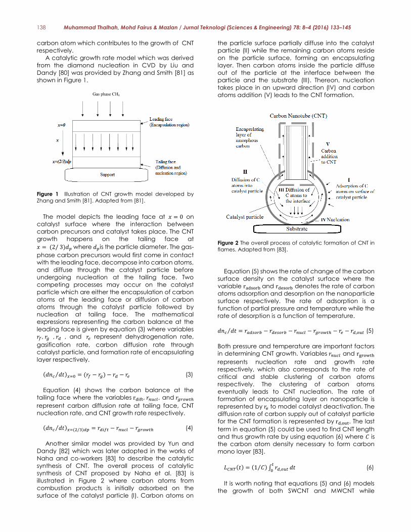
A catalytic growth rate model which was derived
from the diamond nucleation in CVD by Liu and
Dandy [80] was provided by Zhang and Smith [81] as
shown in Figure 1.
Figure 1 Illustration of CNT growth model developed by
Zhang and Smith [81]. Adapted from [81].
The model depicts the leading face at 𝑥 = 0 on
catalyst surface where the interaction between
carbon precursors and catalyst takes place. The CNT
growth happens on the tailing face at
𝑥 = (2/ 3)𝑑𝑝 where 𝑑𝑝is the particle diameter. The gas-
phase carbon precursors would first come in contact
with the leading face, decompose into carbon atoms,
and diffuse through the catalyst particle before
undergoing nucleation at the tailing face. Two
competing processes may occur on the catalyst
particle which are either the encapsulation of carbon
atoms at the leading face or diffusion of carbon
atoms through the catalyst particle followed by
nucleation at tailing face. The mathematical
expressions representing the carbon balance at the
leading face is given by equation (3) where variables
𝑟𝑓, 𝑟𝑔 , 𝑟𝑑 , and 𝑟𝑒 represent dehydrogenation rate,
gasification rate, carbon diffusion rate through
catalyst particle, and formation rate of encapsulating
layer respectively.
(𝑑𝑛𝑐 𝑑𝑡⁄ )𝑥=0 = (𝑟𝑓 − 𝑟𝑔) − 𝑟𝑑 − 𝑟𝑒 (3)
Equation (4) shows the carbon balance at the
tailing face where the variables rdift, 𝑟𝑛𝑢𝑐𝑙, and 𝑟𝑔𝑟𝑜𝑤𝑡ℎ
represent carbon diffusion rate at tailing face, CNT
nucleation rate, and CNT growth rate respectively.
(𝑑𝑛𝑐 𝑑𝑡⁄ )𝑥=(2/3)𝑑𝑝 = 𝑟𝑑𝑖𝑓𝑡 − 𝑟𝑛𝑢𝑐𝑙 − 𝑟𝑔𝑟𝑜𝑤𝑡ℎ (4)
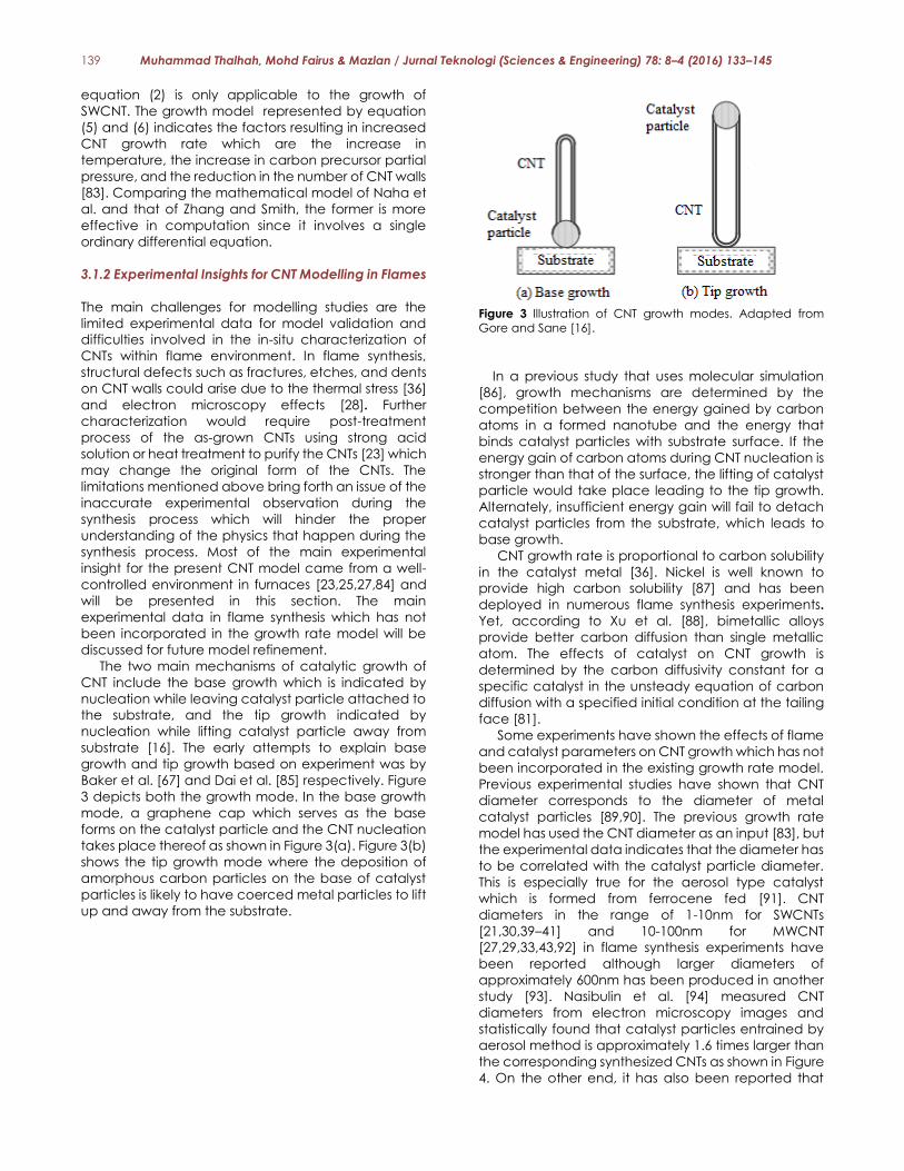
Another similar model was provided by Yun and
Dandy [82] which was later adopted in the works of
Naha and co-workers [83] to describe the catalytic
synthesis of CNT. The overall process of catalytic
synthesis of CNT proposed by Naha et al. [83] is
illustrated in Figure 2 where carbon atoms from
combustion products is initially adsorbed on the
surface of the catalyst particle (I). Carbon atoms on
the particle surface partially diffuse into the catalyst
particle (II) while the remaining carbon atoms reside
on the particle surface, forming an encapsulating
layer. Then carbon atoms inside the particle diffuse
out of the particle at the interface between the
particle and the substrate (III). Thereon, nucleation
takes place in an upward direction (IV) and carbon
atoms addition (V) leads to the CNT formation.
Figure 2 The overall process of catalytic formation of CNT in
flames. Adapted from [83].
Equation (5) shows the rate of change of the carbon
surface density on the catalyst surface where the
variable radsorb and rdesorb denotes the rate of carbon
atoms adsorption and desorption on the nanoparticle
surface respectively. The rate of adsorption is a
function of partial pressure and temperature while the
rate of desorption is a function of temperature.
𝑑𝑛𝑐 𝑑𝑡⁄ = 𝑟𝑎𝑑𝑠𝑜𝑟𝑏 − 𝑟𝑑𝑒𝑠𝑜𝑟𝑏 − 𝑟𝑛𝑢𝑐𝑙 − 𝑟𝑔𝑟𝑜𝑤𝑡ℎ − 𝑟𝑒 − 𝑟𝑑,𝑜𝑢𝑡 (5)
Both pressure and temperature are important factors
in determining CNT growth. Variables 𝑟𝑛𝑢𝑐𝑙 and rgrowth
represents nucleation rate and growth rate
respectively, which also corresponds to the rate of
critical and stable clustering of carbon atoms
respectively. The clustering of carbon atoms
eventually leads to CNT nucleation. The rate of
formation of encapsulating layer on nanoparticle is
represented by 𝑟e to model catalyst deactivation. The
diffusion rate of carbon supply out of catalyst particle
for the CNT formation is represented by rd,out. The last
term in equation (5) could be used to find CNT length
and thus growth rate by using equation (6) where 𝐶 is
the carbon atom density necessary to form carbon
mono layer [83].
𝐿𝐶𝑁𝑇(𝑡) = (1 𝐶⁄ ) ∫ 𝑟𝑑,𝑜𝑢𝑡𝑡
0𝑑𝑡 (6)
It is worth noting that equations (5) and (6) models
the growth of both SWCNT and MWCNT while
139 Muhammad Thalhah, Mohd Fairus & Mazlan / Jurnal Teknologi (Sciences & Engineering) 78: 8–4 (2016) 133–145
equation (2) is only applicable to the growth of
SWCNT. The growth model represented by equation
(5) and (6) indicates the factors resulting in increased
CNT growth rate which are the increase in
temperature, the increase in carbon precursor partial
pressure, and the reduction in the number of CNT walls
[83]. Comparing the mathematical model of Naha et
al. and that of Zhang and Smith, the former is more
effective in computation since it involves a single
ordinary differential equation.
3.1.2 Experimental Insights for CNT Modelling in Flames
The main challenges for modelling studies are the
limited experimental data for model validation and
difficulties involved in the in-situ characterization of
CNTs within flame environment. In flame synthesis,
structural defects such as fractures, etches, and dents
on CNT walls could arise due to the thermal stress [36]
and electron microscopy effects [28]. Further
characterization would require post-treatment
process of the as-grown CNTs using strong acid
solution or heat treatment to purify the CNTs [23] which
may change the original form of the CNTs. The
limitations mentioned above bring forth an issue of the
inaccurate experimental observation during the
synthesis process which will hinder the proper
understanding of the physics that happen during the
synthesis process. Most of the main experimental
insight for the present CNT model came from a well-
controlled environment in furnaces [23,25,27,84] and
will be presented in this section. The main
experimental data in flame synthesis which has not
been incorporated in the growth rate model will be
discussed for future model refinement.
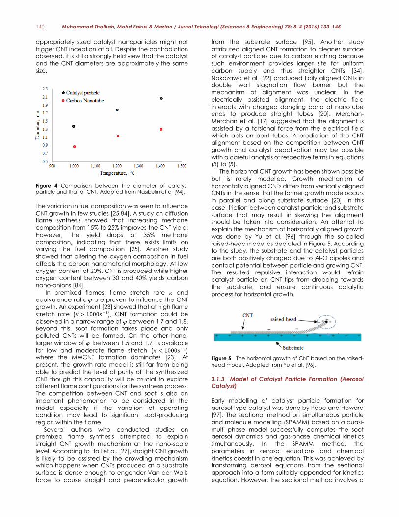
The two main mechanisms of catalytic growth of
CNT include the base growth which is indicated by
nucleation while leaving catalyst particle attached to
the substrate, and the tip growth indicated by
nucleation while lifting catalyst particle away from
substrate [16]. The early attempts to explain base
growth and tip growth based on experiment was by
Baker et al. [67] and Dai et al. [85] respectively. Figure
3 depicts both the growth mode. In the base growth
mode, a graphene cap which serves as the base
forms on the catalyst particle and the CNT nucleation
takes place thereof as shown in Figure 3(a). Figure 3(b)
shows the tip growth mode where the deposition of
amorphous carbon particles on the base of catalyst
particles is likely to have coerced metal particles to lift
up and away from the substrate.
Figure 3 Illustration of CNT growth modes. Adapted from
Gore and Sane [16].
In a previous study that uses molecular simulation
[86], growth mechanisms are determined by the
competition between the energy gained by carbon
atoms in a formed nanotube and the energy that
binds catalyst particles with substrate surface. If the
energy gain of carbon atoms during CNT nucleation is
stronger than that of the surface, the lifting of catalyst
particle would take place leading to the tip growth.
Alternately, insufficient energy gain will fail to detach
catalyst particles from the substrate, which leads to
base growth.
CNT growth rate is proportional to carbon solubility
in the catalyst metal [36]. Nickel is well known to
provide high carbon solubility [87] and has been
deployed in numerous flame synthesis experiments.
Yet, according to Xu et al. [88], bimetallic alloys
provide better carbon diffusion than single metallic
atom. The effects of catalyst on CNT growth is
determined by the carbon diffusivity constant for a
specific catalyst in the unsteady equation of carbon
diffusion with a specified initial condition at the tailing
face [81].
Some experiments have shown the effects of flame
and catalyst parameters on CNT growth which has not
been incorporated in the existing growth rate model.
Previous experimental studies have shown that CNT
diameter corresponds to the diameter of metal
catalyst particles [89,90]. The previous growth rate
model has used the CNT diameter as an input [83], but
the experimental data indicates that the diameter has
to be correlated with the catalyst particle diameter.
This is especially true for the aerosol type catalyst
which is formed from ferrocene fed [91]. CNT
diameters in the range of 1-10nm for SWCNTs
[21,30,39–41] and 10-100nm for MWCNT
[27,29,33,43,92] in flame synthesis experiments have
been reported although larger diameters of
approximately 600nm has been produced in another
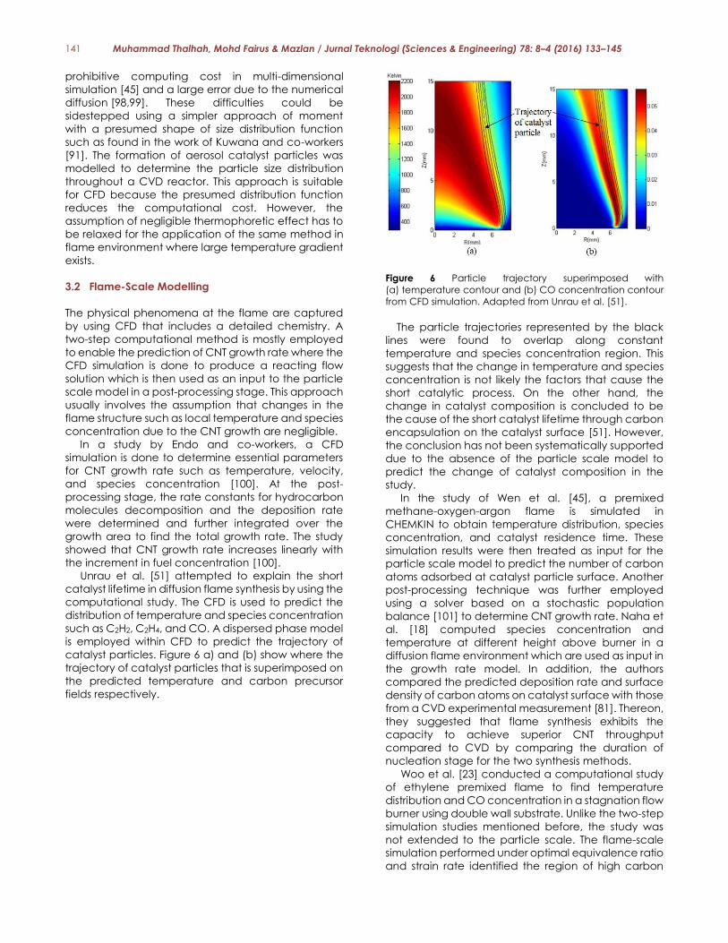
study [93]. Nasibulin et al. [94] measured CNT
diameters from electron microscopy images and
statistically found that catalyst particles entrained by
aerosol method is approximately 1.6 times larger than
the corresponding synthesized CNTs as shown in Figure
4. On the other end, it has also been reported that
140 Muhammad Thalhah, Mohd Fairus & Mazlan / Jurnal Teknologi (Sciences & Engineering) 78: 8–4 (2016) 133–145
appropriately sized catalyst nanoparticles might not
trigger CNT inception at all. Despite the contradiction
observed, it is still a strongly held view that the catalyst
and the CNT diameters are approximately the same
size.
Figure 4 Comparison between the diameter of catalyst
particle and that of CNT. Adapted from Nasibulin et al [94].
The variation in fuel composition was seen to influence
CNT growth in few studies [25,84]. A study on diffusion
flame synthesis showed that increasing methane
composition from 15% to 25% improves the CNT yield.
However, the yield drops at 35% methane
composition, indicating that there exists limits on
varying the fuel composition [25]. Another study
showed that altering the oxygen composition in fuel
affects the carbon nanomaterial morphology. At low
oxygen content of 20%, CNT is produced while higher
oxygen content between 30 and 40% yields carbon
nano-onions [84].
In premixed flames, flame stretch rate 𝜅 and
equivalence ratio 𝜑 are proven to influence the CNT
growth. An experiment [23] showed that at high flame
stretch rate (𝜅 > 1000𝑠−1), CNT formation could be
observed in a narrow range of 𝜑 between 1.7 and 1.8.
Beyond this, soot formation takes place and only
polluted CNTs will be formed. On the other hand,
larger window of 𝜑 between 1.5 and 1.7 is available
for low and moderate flame stretch (𝜅 < 1000𝑠−1)
where the MWCNT formation dominates [23]. At
present, the growth rate model is still far from being
able to predict the level of purity of the synthesized
CNT though this capability will be crucial to explore
different flame configurations for the synthesis process.
The competition between CNT and soot is also an
important phenomenon to be considered in the
model especially if the variation of operating
condition may lead to significant soot-producing
region within the flame.
Several authors who conducted studies on
premixed flame synthesis attempted to explain
straight CNT growth mechanism at the nano-scale
level. According to Hall et al. [27], straight CNT growth
is likely to be assisted by the crowding mechanism
which happens when CNTs produced at a substrate
surface is dense enough to engender Van der Walls
force to cause straight and perpendicular growth
from the substrate surface [95]. Another study
attributed aligned CNT formation to cleaner surface
of catalyst particles due to carbon etching because
such environment provides larger site for uniform
carbon supply and thus straighter CNTs [34].
Nakazawa et al. [22] produced tidily aligned CNTs in
double wall stagnation flow burner but the
mechanism of alignment was unclear. In the
electrically assisted alignment, the electric field
interacts with charged dangling bond at nanotube
ends to produce straight tubes [20]. Merchan-
Merchan et al. [17] suggested that the alignment is
assisted by a torsional force from the electrical field
which acts on bent tubes. A prediction of the CNT
alignment based on the competition between CNT
growth and catalyst deactivation may be possible
with a careful analysis of respective terms in equations
(3) to (5).
The horizontal CNT growth has been shown possible
but is rarely modelled. Growth mechanism of
horizontally aligned CNTs differs from vertically aligned
CNTs in the sense that the former growth mode occurs
in parallel and along substrate surface [20]. In this
case, friction between catalyst particle and substrate
surface that may result in skewing the alignment
should be taken into consideration. An attempt to
explain the mechanism of horizontally aligned growth
was done by Yu et al. [96] through the so-called
raised-head model as depicted in Figure 5. According
to the study, the substrate and the catalyst particles
are both positively charged due to Al-O dipoles and
contact potential between particle and growing CNT.
The resulted repulsive interaction would refrain
catalyst particle on CNT tips from dropping towards
the substrate, and ensure continuous catalytic
process for horizontal growth.
Figure 5 The horizontal growth of CNT based on the raised-
head model. Adapted from Yu et al. [96].
3.1.3 Model of Catalyst Particle Formation (Aerosol
Catalyst)
Early modelling of catalyst particle formation for
aerosol type catalyst was done by Pope and Howard
[97]. The sectional method on simultaneous particle
and molecule modelling (SPAMM) based on a quasi-
multi–phase model successfully computes the soot
aerosol dynamics and gas-phase chemical kinetics
simultaneously. In the SPAMM method, the
parameters in aerosol equations and chemical
kinetics coexist in one equation. This was achieved by
transforming aerosol equations from the sectional
approach into a form suitably appended for kinetics
equation. However, the sectional method involves a
141 Muhammad Thalhah, Mohd Fairus & Mazlan / Jurnal Teknologi (Sciences & Engineering) 78: 8–4 (2016) 133–145
prohibitive computing cost in multi-dimensional
simulation [45] and a large error due to the numerical
diffusion [98,99]. These difficulties could be
sidestepped using a simpler approach of moment
with a presumed shape of size distribution function
such as found in the work of Kuwana and co-workers
[91]. The formation of aerosol catalyst particles was
modelled to determine the particle size distribution
throughout a CVD reactor. This approach is suitable
for CFD because the presumed distribution function
reduces the computational cost. However, the
assumption of negligible thermophoretic effect has to
be relaxed for the application of the same method in
flame environment where large temperature gradient
exists.
3.2 Flame-Scale Modelling
The physical phenomena at the flame are captured
by using CFD that includes a detailed chemistry. A
two-step computational method is mostly employed
to enable the prediction of CNT growth rate where the
CFD simulation is done to produce a reacting flow
solution which is then used as an input to the particle
scale model in a post-processing stage. This approach
usually involves the assumption that changes in the
flame structure such as local temperature and species
concentration due to the CNT growth are negligible.
In a study by Endo and co-workers, a CFD
simulation is done to determine essential parameters
for CNT growth rate such as temperature, velocity,
and species concentration [100]. At the post-
processing stage, the rate constants for hydrocarbon
molecules decomposition and the deposition rate
were determined and further integrated over the
growth area to find the total growth rate. The study
showed that CNT growth rate increases linearly with
the increment in fuel concentration [100].
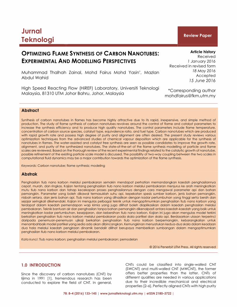
Unrau et al. [51] attempted to explain the short
catalyst lifetime in diffusion flame synthesis by using the
computational study. The CFD is used to predict the
distribution of temperature and species concentration
such as C2H2, C2H4, and CO. A dispersed phase model
is employed within CFD to predict the trajectory of
catalyst particles. Figure 6 a) and (b) show where the
trajectory of catalyst particles that is superimposed on
the predicted temperature and carbon precursor
fields respectively.
Figure 6 Particle trajectory superimposed with
(a) temperature contour and (b) CO concentration contour
from CFD simulation. Adapted from Unrau et al. [51].
The particle trajectories represented by the black
lines were found to overlap along constant
temperature and species concentration region. This
suggests that the change in temperature and species
concentration is not likely the factors that cause the
short catalytic process. On the other hand, the
change in catalyst composition is concluded to be
the cause of the short catalyst lifetime through carbon
encapsulation on the catalyst surface [51]. However,
the conclusion has not been systematically supported
due to the absence of the particle scale model to
predict the change of catalyst composition in the
study.
In the study of Wen et al. [45], a premixed
methane-oxygen-argon flame is simulated in
CHEMKIN to obtain temperature distribution, species
concentration, and catalyst residence time. These
simulation results were then treated as input for the
particle scale model to predict the number of carbon
atoms adsorbed at catalyst particle surface. Another
post-processing technique was further employed
using a solver based on a stochastic population
balance [101] to determine CNT growth rate. Naha et
al. [18] computed species concentration and
temperature at different height above burner in a
diffusion flame environment which are used as input in
the growth rate model. In addition, the authors
compared the predicted deposition rate and surface
density of carbon atoms on catalyst surface with those
from a CVD experimental measurement [81]. Thereon,
they suggested that flame synthesis exhibits the
capacity to achieve superior CNT throughput
compared to CVD by comparing the duration of
nucleation stage for the two synthesis methods.
Woo et al. [23] conducted a computational study
of ethylene premixed flame to find temperature
distribution and CO concentration in a stagnation flow
burner using double wall substrate. Unlike the two-step
simulation studies mentioned before, the study was
not extended to the particle scale. The flame-scale
simulation performed under optimal equivalence ratio
and strain rate identified the region of high carbon
142 Muhammad Thalhah, Mohd Fairus & Mazlan / Jurnal Teknologi (Sciences & Engineering) 78: 8–4 (2016) 133–145
precursors to be up to 40 mm above the plate. The
authors also reported the appropriate temperature for
MWCNT formation is between 950 K and 1150 K but this
conclusion has yet to be confirmed with a coupled
simulation [23].
A study by Kuwana et.al [91] provided a model for
iron nanoparticle formation in a CVD reactor. The
temperature field in the reactor was calculated
before solving the particle dynamic equation to
predict the iron nanoparticle formation at the furnace
entrance [100]. The nucleation and surface growth of
iron nanoparticles were described by the number
density and volume fraction which are implemented
within a two-equation model. Ultimately, distribution of
particle diameter across a CVD reactor was
produced. However, it is important to note that the
study assumed uniform temperature gradient [91],
which needs to be refined for flame application.
Another approach to support the CNT formation
modelling at flame scale is by studying the chemical
kinetics side of CNT flame synthesis. Hall et al. [27]
provided chemical kinetics simulation to predict the
gas-phase composition for different types of fuel in
premixed flames. From that, a linear relationship
between carbon precursor concentration and
diameter of CNTs was identified. As the hydrocarbon
content in fuel source increase, so does the size of
CNTs [27]. Similar relation was observed for the
influence of partial pressure of CO and H2 on the
diameter of CNTs. Gopinath et al. [32] presented a 1-
D chemical kinetic model for an ethylene premixed
flame environment. The gas-phase species are
tabulated at various heights within the post-flame
region where the unburned hydrocarbon molecules is
proportional to the equivalence ratio.
A similar modelling concept by Li et al. [44]
provided spatial distribution of gas-phase species in a
counterflow diffusion flame. The synthesis region was
experimentally determined and the distribution of
carbon precursors was obtained from computational
works. Based on the distribution of carbon monoxide,
acetylene, ethylene, ethane, and methyl radical,
which fall inside the synthesis region, the carbon
precursors for CNT formation are identified.
3.3 Towards a Coupled Multi-Scale Modelling of
Flame Synthesis
From the review provided on the computational study
of flame synthesis, it could be inferred that the
coupling of particle-scale and flame scale model is
majorly unidirectional. To the best of authors
knowledge, two-way effect between the flame and
the particle scale has never been considered before
and this is mainly due to the prohibitive computational
cost to resolve the two different length scales of flame
and particle respectively. Particle scale and flame
scale simulation are always processed independently
in a one-way coupling mode. A two-way coupling
method which models the two-way interaction
between different scales will allow the
multidimensional CFD simulation to be a helpful tool to
optimize different flame configurations for CNT
synthesis. This can be done with a reasonable
computational cost by introducing a subgrid model
which can be implemented in a surface chemistry
model for a substrate based catalyst or in a dispersed
phase model for an aerosol based catalyst. Then, the
more advanced optimization strategies as described
in section 0 can be explored computationally.
4.0 CONCLUSION
Flame synthesis is an attractive method of producing
CNT due to its simple and cost effective process.
Several optimization techniques from the advanced
CVD research, which are possible to be adopted in
flame synthesis to enhance the yield rate, the CNT
quality, and the size, are presented. Among other
optimization methods, the water-assisted synthesis
and the catalyst-free synthesis are deemed suitable
for the improvement of the purity and alignment of the
synthesized CNT in flames. An accurate modelling of
CNT synthesis in flames is essential to optimize growth
behaviour that varies with different types of synthesis
parameters such as flame temperature, carbon
source, type of catalyst and substrate, and sampling
region. The flame synthesis could be described in two
scales which are the particle and the flame scales.
The existing particle scale models that describe the
interaction between carbon precursors and catalyst
particles leading to CNT growth could be coupled
with the flame scale computation to allow two-way
coupling between different scales. The existing
mathematical model on CNT growth rate could be
enhanced based on some experimental observations.
Further refinement may allow the model to predict the
diameter based on the size of catalyst particle. The
flame scale modelling majorly involves CFD and
chemical kinetics modelling to predict the flame
structure such as temperature, catalyst, and species
distribution. A fully coupled particle scale and
reacting flow simulation will allow the optimization of
the CNT synthesis in flames. However, extensive studies
are required to develop such a comprehensive
model.
Acknowledgement
This research was funded by the Research University
Grant (RUG) with reference number PY/2014/03586
awarded by Universiti Teknologi Malaysia.
References [1] Iijima, S. 1991. Helical microtubules of graphitic carbon.
Nature. 354 (6348): 56–58.
[2] Wood, J. 2007. Putting the heat on nanotubes. Nano
Today. 2 (6): 8.
[3] Zakaria, M.R., H.M. Akil, M.H.A. Kudus, and S.S.M. Saleh.
2014. Enhancement of tensile and thermal properties of
143 Muhammad Thalhah, Mohd Fairus & Mazlan / Jurnal Teknologi (Sciences & Engineering) 78: 8–4 (2016) 133–145
epoxy nanocomposites through chemical hybridization of
carbon nanotubes and alumina. Compos. Part A Appl. Sci.
Manuf. 66: 109–116.
[4] Spitalsky, Z., D. Tasis, K. Papagelis, and C. Galiotis. 2010.
Carbon nanotube–polymer composites: Chemistry,
processing, mechanical and electrical properties. Prog.
Polym. Sci. 35 (3): 357–401.
[5] Hu, Z. and X. Lu. 2014. Carbon Nanotubes and Graphene,
2nd ed. Elsevier Ltd. 165–200.
[6] Wang, A., Y. Cheng, H. Zhang, Y. Hou, Y. Wang, and J. Liu.
2014. Effect of Multi-Walled Carbon Nanotubes and
Conducting Polymer on Capacitance of Mesoporous
Carbon Electrode. J. Nanosci. Nanotechnol. 14 (9): 7015–
7021.
[7] Srivastava, A., A.K. Srivastava, and O.N. Srivastava. 2001.
Curious aligned growth of carbon nanotubes under
applied electric field. Carbon. 39 (2) 201–206.
[8] Sealy, C. 2007. Carbon nanotubes offer a crack cure. Nano
Today. 2 (6): 10.
[9] Sandler, J.K., S. Pegel, M. Cadek, F. Gojny, M. van Es, J.
Lohmar, W.J. Blau, K. Schulte, A.H. Windle, and M.S.P.
Shaffle. 2004. A comparative study of melt spun
polyamide-12 fibres reinforced with carbon nanotubes and
nanofibres. Polymer. 45 (6): 2001–2015.
[10] Coleman, J.N., U. Khan, W.J. Blau, and Y.K. Gun’ko. 2006.
Small but strong: A review of the mechanical properties of
carbon nanotube-polymer composites. Carbon. 44 (9):
1624–1652.
[11] Sealy, C. 2013. Carbon nanotubes target tumors in two
steps. Nano Today. 8 (6): 557.
[12] Liu, Z., X. Sun, N. Nakayama-Ratchford, and H. Dai. 2007.
Supramolecular chemistry on water-soluble carbon
nanotubes for drug loading and delivery. ACS Nano. 1 (1):
50–56.
[13] Kam, N.W.S., M. O’Connell, J.A. Wisdom, and H. Dai. 2005.
Carbon nanotubes as multifunctional biological
transporters and near-infrared agents for selective cancer
cell destruction. Proc. Natl. Acad. Sci. U. S. A. 102 (33):
11600–11605.
[14] Han, Z.J., A.E. Rider, C. Fisher, T. van der Laan, S. Kumar, I.
Levchenko, and K. Ostrikov. 2014. Carbon Nanotubes and
Graphene. 2nd ed. Elsevier Ltd. 279–312.
[15] Eatemadi, A., H.D.H.K.M. Kouhi, N. Zarghami, A.
Akbarzadeh, M. Abasi, Y. Hanifehpour, and S.W. Joo. 2014.
Carbon nanotubes: properties, synthesis, purification, and
medical applications. Nanoscale Res. Lett. 9 (393): 1–13.
[16] Gore, J.P and A. Sane. 2011. Synthesis. Characterization,
Applications. InTech. 121–146.
[17] Merchan-Merchan, W., A. V. Saveliev, L. Kennedy, and
W.C. Jimenez. 2010. Combustion synthesis of carbon
nanotubes and related nanostructures. Prog. Energy
Combust. Sci. 36 (6): 696–727.
[18] Naha, S., S. Sen, A.K. De, and I.K. Puri. 2007. A detailed
model for the flame synthesis of carbon nanotubes and
nanofibers. Proc. Combust. Inst. 31 (2): 1821–1829.
[19] Mittal, G., V. Dhand, K.Y. Rhee, H.J. Kim, and D.H. Jung.
2015. Carbon nanotubes synthesis using diffusion and
premixed flame methods: a review. Carbon Lett. 16 (1:) 1–
10.
[20] Seah, C.M., S.P. Chai, and A.R. Mohamed. 2011. Synthesis
of aligned carbon nanotubes. Carbon. 49 (14): 4613–4635.
[21] Unrau, C.J., R.L. Axelbaum, P. Biswas, and P. Fraundorf.
2007. Synthesis of single-walled carbon nanotubes in oxy-
fuel inverse diffusion flames with online diagnostics. Proc.
Combust. Inst. 31: 1865–1872.
[22] Nakazawa, S., T. Yokomori, and M. Mizomoto. 2005. Flame
synthesis of carbon nanotubes in a wall stagnation flow.
Chem. Phys. Lett. 403 (1-3): 158–162.
[23] Woo, S.K., Y.T. Hong, and O.C. Kwon. 2009. Flame-synthesis
limits and self-catalytic behavior of carbon nanotubes
using a double-faced wall stagnation flow burner.
Combust. Flame. 156 (10): 1983–1992.
[24] Vander Wal, R.L., and L.J. Hall. 2002. Ferrocene as a
precursor reagent for metal-catalyzed carbon nanotubes:
Competing effects. Combust. Flame. 130 (1-2): 27–36.
[25] Hou, S.S., D.H. Chung, and T.H. Lin. 2009. High-yield synthesis
of carbon nano-onions in counterflow diffusion flames.
Carbon. 47 (7): 938–947.
[26] Hu, W.C., S.S. Hou, and T.H. Lin. 2014. Analysis on Controlling
Factors for the Synthesis of Carbon Nanotubes and Nano-
Onions in Counterflow Diffusion Flames. J. Nanosci.
Nanotechnol. 14 (7): 5363–5369.
[27] Hall, B., C. Zhuo, Y.A. Levendis, and H. Richter. 2011.
Influence of the fuel structure on the flame synthesis of
carbon nanomaterials. Carbon. 49 (11): 3412–3423.
[28] Vander Wal, R.L., T.M. Ticich, and V.E. Curtis. 2000. Diffusion
flame synthesis of single-walled carbon nanotubes. Chem.
Phys. Lett. 323 (3-4): 217–223.
[29] Vander Wal, R.L. and T.M. Ticich. 2001. Comparative Flame
and Furnace Synthesis of Single-Walled Carbon
Nanotubes. Chem. Phys. Lett. 336 (1-2): 24–32.
[30] Unrau, C.J. and R.L. Axelbaum. 2010. Gas-phase synthesis
of single-walled carbon nanotubes on catalysts producing
high yield. Carbon 48 (5): 1418–1424.
[31] Vander Wal, R.L. 2002. Flame synthesis of Ni-catalyzed
nanofibers. Carbon. 40 (12): 2101–2107.
[32] Gopinath, P. and J. Gore. 2007. Chemical kinetic
considerations for postflame synthesis of carbon nanotubes
in premixed flames using a support catalyst. Combust.
Flame. 151 (3): 542–550.
[33] Zhuo, C., B. Hall, H. Richter, and Y. Levendis. 2010. Synthesis
of carbon nanotubes by sequential pyrolysis and
combustion of polyethylene. Carbon. 48 (14): 4024–4034.
[34] Vander Wal, R.L., L.J. Hall, and G.M. Berger. 2002. The
chemistry of premixed flame synthesis of carbon
nanotubes using supported catalysts. Proc. Combust. Inst.
29 (1): 1079–1085.
[35] Xu, F., X. Liu, and S.D. Tse. 2006. Synthesis of carbon
nanotubes on metal alloy substrates with voltage bias in
methane inverse diffusion flames. Carbon. 44 (3): 570–577.
[36] Arana, C.P., I.K. Puri, and S. Sen. 2005. Catalyst influence on
the flame synthesis of aligned carbon nanotubes and
nanofibers. Proc. Combust. Inst. 30 (2): 2553–2560.
[37] Merchan-Merchan, W., A. V. Saveliev, and L.A. Kennedy.
2004. High-rate flame synthesis of vertically aligned carbon
nanotubes using electric field control. Carbon. 42 (3): 599–
608.
[38] Merchan-Merchan, W., A. V. Saveliev, and L.A. Kennedy.
2006. Flame nanotube synthesis in moderate electric fields:
From alignment and growth rate effects to structural
variations and branching phenomena. Carbon. 44 (15):
3308–3314.
[39] Memon, N.K., F. Xu, G. Sun, S.J.B. Dunham, B.H. Kear, and
S.D. Tse. 2013. Flame synthesis of carbon nanotubes and
few-layer graphene on metal-oxide spinel powders.
Carbon. 63: 478–486.
[40] Memon, N.K., Multiple Inverse-Diffusion Flame Synthesis of
Carbon Nanomaterials, PhD Thesis, Rutgers State University
of New Jersey, 2012.
[41] Unrau, C.J., R.L. Axelbaum, and P. Fraundorf. 2010. Single-
walled carbon nanotube formation on iron oxide catalysts
in diffusion flames. J. Nanoparticle Res. 12 (6): 2125–2133.
[42] Lee, G.W., J. Jurng, and J. Hwang. 2004. Formation of Ni-
catalyzed multiwalled carbon nanotubes and nanofibers
on a substrate using an ethylene inverse diffusion flame.
Combust. Flame. 139 (1-2): 167–175.
[43] Lee, G.J., J. Jurng, and J. Hwang. 2004. Synthesis of carbon
nanotubes on a catalytic metal substrate by using an
ethylene inverse diffusion flame. Carbon. 42 (3): 682–685.
[44] Li, T.X., K. Kuwana, K. Saito, H. Zhang, and Z. Chen. 2009.
Temperature and carbon source effects on methane-air
flame synthesis of CNTs. Proc. Combust. Inst. 32 (2): 1855–
1861.
[45] Wen, J.Z., M. Celnik, H. Richter, M. Treska, J.B. Vander
Sande, and M. Kraft. 2008. Modelling study of single walled
144 Muhammad Thalhah, Mohd Fairus & Mazlan / Jurnal Teknologi (Sciences & Engineering) 78: 8–4 (2016) 133–145
carbon nanotube formation in a premixed flame. J. Mater.
Chem. 18 (13): 1582.
[46] Moisala, A., A.G. Nasibulin, D.P. Brown, H. Jiang, L.
Khriachtchev, and E.I. Kauppinen. 2006. Single-walled
carbon nanotube synthesis using ferrocene and iron
pentacarbonyl in a laminar flow reactor. Chem. Eng. Sci.
61 (13): 4393–4402.
[47] Singer, J.M. and J. Grumer. 1958. Carbon Formation in Very
Rich Hydrocarbon-Air Flames-I. Studies of Chemical
Content, Temperature, Ionization and Particulate Matter.
Symp. Combust. 7 (1): 559–569.
[48] Vander Wal, R.L. 2002. Fe-catalyzed single-walled carbon
nanotube synthesis within a flame environment. Combust.
Flame. 130 (1-2): 37–47.
[49] Yuan, L., T. Li, and K. Saito. 2003. Growth mechanism of
carbon nanotubes in methane diffusion flames. Carbon. 41
(10): 1889–1896.
[50] Zhu, L., Y. Xiu, D.W. Hess, and C.P. Wong. 2005. Aligned
carbon nanotube stacks by water-assisted selective
etching. Nano Lett. 5 (12): 2641–2645.
[51] Unrau, C.J., V.R. Katta, and R.L. Axelbaum. 2010.
Characterization of diffusion flames for synthesis of single-
walled carbon nanotubes. Combust. Flame. 157 (9): 1643–
1648.
[52] Chun Zeng, H. 2007. Ostwald Ripening: A Synthetic
Approach for Hollow Nanomaterials. Curr. Nanosci. 3 (2):
177–181.
[53] Amama, P.B., C.L. Pint, L. McJilton, S.M. Kim, E. A. Stach, P.T.
Murray, R.H. Hauge, and B. Maruyama. 2009. Role of water
in super growth of single-walled carbon nanotube carpets.
Nano Lett. 9 (1): 44–49.
[54] Yamada, T., A. Maigne, M. Yudasaka, K. Mizuno, D.N.
Futaba, M. Yumura, S. Iijima, and K. Hata. 2008. Revealing
the secret of water-assisted carbon nanotube synthesis by
microscopic observation of the interaction of water on the
catalysts. Nano Lett. 8 (12): 4288–4292.
[55] Liu, H., Y. Zhang, R. Li, X. Sun, F. Wang, Z. Ding, P. Merel, and
S. Desilets. 2010. Aligned synthesis of multi-walled carbon
nanotubes with high purity by aerosol assisted chemical
vapor deposition: Effect of water vapor. Appl. Surf. Sci. 256
(14): 4692–4696.
[56] Li, X., A. Westwood, A. Brown, R. Brydson, and B. Rand. 2008.
Water assisted synthesis of clean single-walled carbon
nanotubes over a Fe2O3/Al2O3 binary aerogel catalyst.
New Carbon Mater. 23 (4): 351–355.
[57] Futaba, D.N., K. Hata, T. Yamada, K. Mizuno, M. Yumura,
and S. Iijima. 2005. Kinetics of Water-Assisted Single-Walled
Carbon Nanotube Synthesis Revealed by a Time-Evolution
Analysis. Phys. Rev. Lett. 95 (5:) 056104.
[58] Hata, K., D.N. Futaba, K. Mizuno, T. Namai, M. Yumura, and
S. Iijima. 2004. Water-assisted highly efficient synthesis of
impurity-free single-walled carbon nanotubes. Science.
306 (5700): 1362–1364.
[59] Yoshida, A., T. Udagawa, Y. Momomoto, H. Naito, and Y.
Saso. 2013. Experimental study of suppressing effect of fine
water droplets on propane/air premixed flames stabilized
in the stagnation flowfield. Fire Saf. J. 58: 84–91.
[60] Zhu, Z., Y. Lu, D. Qiao, S. Bai, T. Hu, L. Li, and J. Zheng. 2005.
Self-catalytic behavior of carbon nanotubes. J. Am. Chem.
Soc. 127 (45): 15698–156989.
[61] Romero, P., R. Oro, M. Campos, J.M. Torralba, and R.
Guzman de Villoria. 2015. Simultaneous synthesis of
vertically aligned carbon nanotubes and amorphous
carbon thin films on stainless steel. Carbon. 82: 31–38.
[62] Merchan-Merchan, W., A. Saveliev, L. A. Kennedy, and A.
Fridman. 2002. Formation of carbon nanotubes in counter-
flow, oxy-methane diffusion flames without catalysts.
Chem. Phys. Lett. 354 (1-2): 20–24..
[63] Martin. I, G. Rius, P. Atienzar, L. Teruel, N. Mestres, F. Perez-
Murano, H. Garcia, P. Godignon, A. Corma, and E. Lora-
Tamayo. 2008. CVD oriented growth of carbon nanotubes
using AlPO4-5 and L type zeolites. Microelectron. Eng. 85 (5-
6): 1202–1205.
[64] Yuan, D., L. Ding, H. Chu, Y. Feng, T.P. McNicholas, and J.
Liu. 2008. Horizontally aligned single-walled carbon
nanotube on quartz from a large variety of metal catalysts.
Nano Lett. 8 (8): 2576-2579.
[65] Liu, B., W. Ren, L. Gao, S. Li, S. Pei, C. Liu, C. Jiang, and H.M.
Cheng. 2009. Metal-catalyst-free growth of single-walled
carbon nanotubes. J. Am. Chem. Soc. 131 (6): 2082–2083.
[66] Simon, A., M. Seyring, S. Kamnitz, H. Richter, I. Voigt, M.
Rettenmayr, and U. Ritter. 2015. Carbon nanotubes and
carbon nanofibers fabricated on tubular porous Al2O3
substrates. Carbon. 90: 25–33.
[67] Baker, R.T.K., M.A. Barber, P.S. Harris, F.S. Feates, and R.J.
Waite. 1972. Nucleation and Growth of Carbon Deposits
from the Nickel Catalyzed Decomposition of Acetylene. J.
Catal. 26 (1): 51–62.
[68] Borowiak-Palen, E., A. Bachmatiuk, M.H. Rümmeli, T.
Gemming, M. Kruszynska, and R.J. Kalenczuk. 2008.
Modifying CVD synthesised carbon nanotubes via the
carbon feed rate. Phys. E Low-Dimensional Syst.
Nanostructures. 40 (7): 2227–2230.
[69] Park, S., W. Song, Y. Kim, I. Song, S.H. Kim, S. Il Lee, S.W. Jang,
and C.Y. Parkl. 2014. Effect of growth pressure on the
synthesis of vertically aligned carbon nanotubes and their
growth termination. J. Nanosci. Nanotechnol. 14 (7): 5216–
20.
[70] Maruyama, S., R. Kojima, Y. Miyauchi, S. Chiashi, and M.
Kohno. 2002. Low-temperature synthesis of high-purity
single-walled carbon nanotubes from alcohol. Chem. Phys.
Lett. 360 (3-4): 229–234. 2.
[71] Qian, W., H. Yu, F. Wei, Q. Zhang, and Z. Wang. 2002.
Synthesis of carbon nanotubes from liquefied petroleum
gas containing sulfur. Carbon. 40 (15): 2968–2970.
[72] Huang, J., Q. Zhang, F. Wei, W. Qian, D. Wang, and L. Hu.
2008. Liquefied petroleum gas containing sulfur as the
carbon source for carbon nanotube forests. Carbon. 46 (2):
291–296.
[73] Zhao, J., X. Guo, Q. Guo, L. Gu, Y. Guo, and F. Feng. 2011.
Growth of carbon nanotubes on natural organic precursors
by chemical vapor deposition. Carbon. 49 (6): 2155–2158.
[74] Deep, A. and N. Arya. 2012. Optimization of Flame Synthesis
of CNT Structures using Statistical Design of Experiments (
SDOE ). Int. J. Sci. Eng. Res. 3 (11): 305–312.
[75] Pan, C. and X. Xu. 2002. Synthesis of carbon nanotubes
from ethanol flame. J. Mater. Sci. Lett. 21 (15): 1207–1209.
[76] Bajad, G.S., S.K. Tiwari, and R.P. Vijayakumar. 2015.
Synthesis and characterization of CNTs using
polypropylene waste as precursor. Mater. Sci. Eng. B. 194:
68–77.
[77] Tsai, S.H., C.T. Shiu, S.H. Lai, and H.C. Shih. 2002. Tubes on
tube—a novel form of aligned carbon nanotubes. Carbon.
40 (9): 1597–1600.
[78] Santini, C.A., P.M. Vereecken, and C. Van Haesendonck.
2012. Growth of carbon nanotube branches by
electrochemical decoration of carbon nanotubes. Mater.
Lett. 88: 33–35.
[79] Ngo, Q., A.M. Cassell, V. Radmilovic, J. Li, S. Krishnan, M.
Meyyappan, andn C.Y. Yang. 2007. Palladium catalyzed
formation of carbon nanofibers by plasma enhanced
chemical vapor deposition. Carbon. 45 (2): 424–428.
[80] Liu, H. and D.S. Dandy. 1996. Nucleation Kinetics Of
Diamond On Carbide-Forming Substrates During Cvd — I .
Transient Nucleation Stage. J. Electrochem. Soc. 143 (3):
1104–1109.
[81] Zhang, Y. and K. Smith. 2005. A kinetic model of CH4
decomposition and filamentous carbon formation on
supported Co catalysts. J. Catal. 231 (2): 354–364.
[82] Yun, J. and D.S. Dandy. 2005. A kinetic model of diamond
nucleation and silicon carbide interlayer formation during
chemical vapor deposition. Diam. Relat. Mater. 14 (8):
1377–1388.
[83] Naha, S. and I.K. Puri. 2008. A model for catalytic growth of
carbon nanotubes. J. Phys. D. Appl. Phys. 41 (6): 065304.
145 Muhammad Thalhah, Mohd Fairus & Mazlan / Jurnal Teknologi (Sciences & Engineering) 78: 8–4 (2016) 133–145
[84] Hou, S.S., W.C. Huang, and T.H. Lin. 2012. Flame synthesis of
carbon nanostructures using mixed fuel in oxygen-enriched
environment. J. Nanoparticle Res. 14 (11): 1–11.
[85] Dai, H., A.G. Rinzler, P. Nikolaev, A. Thess, D.T. Colbert, and
R.E. Smalley. 1996. Single-wall nanotubes produced by
metal-catalyzed disproportionation of carbon monoxide.
Chem. Phys. Lett. 260 (3-4): 471–475.
[86] Banerjee, S., S. Naha, and I.K. Puri. 2008. Molecular
simulation of the carbon nanotube growth mode during
catalytic synthesis. Appl. Phys. Lett. 92 (23): 2006–2009.
[87] Lander, J.J., H.E. Kern, and A.L. Beach. 1952. Solubility and
Diffusion Coefficient of Carbon in Nickel: Reaction Rates of
Nickel-Carbon Alloys with Barium Oxide. J. Appl. Phys. 23
(12): 1305.
[88] Xu, F., H. Zhao, and S.D. Tse. 2007. Carbon nanotube
synthesis on catalytic metal alloys in methane/air
counterflow diffusion flames. Proc. Combust. Inst. 31 (2):
1839–1847.
[89] Cheung, C.L., A. Kurtz, H. Park, and C.M. Lieber. 2002.
Diameter-controlled synthesis of carbon nanotubes. J.
Phys. Chem. B. 106 (10): 2429–2433.
[90] Michalkiewicz, B. and J. Majewska. 2014. Diameter-
controlled carbon nanotubes and hydrogen production.
Int. J. Hydrogen Energy. 39 (9): 4691–4697.
[91] Kuwana, K. and K. Saito. 2005. Modeling CVD synthesis of
carbon nanotubes: Nanoparticle formation from
ferrocene. Carbon. 43 (10): 2088–2095.
[92] Hou, S.S., D.H. Chung, and T.H. Lin. 2009. Flame synthesis of
carbon nanotubes in a rotating counterflow. J. Nanosci.
Nanotechnol. 9 (8): 4826–4833.
[93] Manciu, F.S., J. Camacho, and A.R. Choudhuri. 2008. Flame
synthesis of multi-walled carbon nanotubes using CH4-H2
fuel blends. Fullerenes, Nanotub. Carbon Nanostructures.
16 (4): 231–246.
[94] Nasibulin, A.G., P. V. Pikhitsa, H. Jiang, and E.I. Kauppinen.
2005. Correlation between catalyst particle and single-
walled carbon nanotube diameters. Carbon. 43 (11): 2251–
2257.
[95] Chen, L.C., C.Y. Wen, C.H. Liang, W.K. Hong, K.J. Chen, H.C.
Cheng, C.S. Shen, C.T. Wu, and K.H. Chen. 2002. Controlling
Steps During Early Stages of the Aligned Growth of Carbon
Nanotubes Using Microwave Plasma Enhanced Chemical
Vapor Deposition. Adv. Funct. Mater. 12 (10): 687–692.
[96] Yu, Q., G. Qin, H. Li, Z. Xia, Y. Nian, and S.S. Pei. 2006.
Mechanism of horizontally aligned growth of single-wall
carbon nanotubes on R-plane sapphire. J. Phys. Chem. B.
110 (45): 22676–22680.
[97] Pope, C.J. and J.B. Howard. 1997. Simultaneous Particle
and Molecule Modeling (SPAMM): An Approach for
Combining Sectional Aerosol Equations and Elementary
Gas-Phase Reactions. Aerosol Sci. Technol. 27 (1): 73–94.
[98] Ramponi, R. and B. Blocken. 2012. CFD simulation of cross-
ventilation flow for different isolated building
configurations: Validation with wind tunnel measurements
and analysis of physical and numerical diffusion effects. J.
Wind Eng. Ind. Aerodyn. 104-106: 408–418.
[99] Mitrakos, D., E. Hinis, and C. Housiadas. 2007. Sectional
Modeling of Aerosol Dynamics in Multi-Dimensional Flows.
Aerosol Sci. Technol. 41 (12): 1076–1088.
[100]Endo, H., K. Kuwana, K. Saito, D. Qian, R. Andrews, and E.A.
Grulke. 2004. CFD prediction of carbon nanotube
production rate in a CVD reactor. Chem. Phys. Lett. 387 (4-
6): 307–311.
[101]Celnik, M., R. West, N. Morgan, M. Kraft, A. Moisala, J. Wen,
W. Green, and H. Richter. 2008. Modelling gas-phase
synthesis of single-walled carbon nanotubes on iron
catalyst particles. Carbon. 46 (3): 422–433.