Embed Size (px)
DESCRIPTION
Manual for jr xp 8103 transmitter
Citation preview

AIRCRAFT SYSTEM - A IRPLANE MODE
USER M
AN
UA
L
AIRCRAFT SYSTEM - GL IDER MODE
HEL ICOPTER SYSTEM - HEL ICOPTER MODE
8 C H A N N E L S 1 0 M O D E L M E M O R Y 3 M O D E L T Y P E S • Z P C M / P P M S E L E C T A B L E
THE
ULTIMATE
RADIO CONTROL
SYSTEM


XP8103 2

Airp
lane
Mod
eH
elic
opte
r M
ode
Glid
er M
ode
1-2-
3 Pr
ogra
mm
ing
Syst
em S
et-U
p M
ode
Func
tion
Mod
e
EN
T
UP
– M
OD
E –
DN
ON
Push
thes
e tw
o bu
ttons
simul
tane
ously
and
hold
.
Turn
the
pow
er s
witc
hO
N (u
p).
EN
T
UP
– M
OD
E –
DN
Push
thes
e tw
o bu
ttons
simul
tane
ously
.
Turn
the
pow
er s
witc
hO
N (u
p).
1
EN
T
UP
– M
OD
E –
DN
Scro
ll th
roug
h op
tions
usin
g on
e of
thes
ebu
ttons
.32
ON
EN
T
UP
– M
OD
E –
DN
Scro
ll th
roug
h th
efu
nctio
ns u
sing
one
ofth
ese
butto
ns.
1 32
[INFO
-DIS
P]
↕
Pg. 2
8In
form
atio
n Di
spla
y
Pg. 2
9M
odel
Sel
ect a
nd C
opy
Pg. 2
9M
odel
Nam
e In
put
Pg. 3
0M
odel
Typ
e Se
lect
ion
Func
tion
Pg. 3
0Da
ta R
eset
Pg. 3
1M
odul
atio
n Se
lect
ion
Pg. 3
2Da
ta T
rans
fer b
etwe
en tr
aqns
mitt
ers
Pg. 3
4W
ing
Type
Sel
ectio
n
Pg. 3
5Sp
oile
r Cha
nnel
Inpu
t Sel
ectio
n
Pg. 3
6Du
al R
ate
Expo
nent
ial
Pg. 3
8Re
vers
e Sw
itch
Pg. 3
8Su
b-Tr
im
Pg. 3
9Tr
avel
Adj
ust (
end
poin
t adj
ustm
ent)
Pg. 3
9El
evat
or to
Fla
p M
ixing
Pg. 4
0Ai
lero
n to
Rud
der M
ixing
Pg. 4
1La
ndin
g Sy
stem
Pg. 4
2Sn
ap R
oll
Pg. 4
4Di
ffere
ntia
l Aile
ron
Mixi
ng (o
nly
if fla
pero
n or
elev
ons
mixi
ng is
act
ive)
Pg. 4
5Tr
im O
ffset
Mem
ory
Pg. 4
6Fl
ap K
nob
Ope
ratin
g Va
lue
Adju
stm
ent
Pg. 4
7Pr
ogra
mm
able
Mixi
ng 1
Pg. 4
7Pr
ogra
mm
able
Mixi
ng 2
Pg. 4
7Pr
ogra
mm
able
Mixi
ng 3
Pg. 4
7Pr
ogra
mm
able
Mixi
ng 4
Pg. 4
7Pr
ogra
mm
able
Mixi
ng 5
Pg. 4
7Pr
ogra
mm
able
Mixi
ng 6
Pg. 5
0Fa
il-Sa
fe/H
old
(PCM
Onl
y)
Pg. 5
2Tr
aine
r
Pg. 5
4Ti
mer
Pg. 5
5Se
rvo
Out
put V
alue
s
Pg. 1
06In
form
atio
n Di
spla
y
Pg. 1
06M
odel
Sel
ect A
nd C
opy
Func
tion
Pg. 1
07M
odel
Nam
e In
put
Pg. 1
08M
odel
Typ
e Se
lect
ion
Func
tion
Pg. 1
08Da
ta R
eset
Pg. 1
09M
odul
atio
n Se
lect
ion
Pg. 1
10M
odel
Dat
a Tr
ansf
er
Pg. 1
12W
ing
Type
Sel
ectio
n
Pg.1
12Fl
ap C
hann
el In
put S
elec
tion
[INF
O-D
ISP
] ↕
Pg. 1
13Du
al R
ate/
Expo
nent
ial
Pg. 1
14Re
vers
e Sw
itch
Pg. 1
14Su
b-Tr
im
Pg. 1
15Tr
avel
Adj
ustm
ent
Pg. 1
15El
evat
or T
o Fl
ap M
ixing
Pg. 1
16Ai
lero
n To
Fla
p M
ixing
Pg. 1
17Di
ffere
ntia
l
Pg. 1
18Fl
ap T
o El
evat
or M
ixing
Pg. 1
19Fl
ap T
o Ai
lero
n M
ixing
Pg. 1
20Ai
lero
n To
Rud
der M
ixing
Pg. 1
21Bu
tterfl
y M
ixing
(Cro
w)
Pg. 1
22Du
al F
lap
Trim
Pg. 1
23Tr
im O
ffset
Pg. 1
25Pr
ogra
mm
able
Mixi
ng
Pg. 1
25Pr
ogra
mm
able
Mixi
ng
Pg. 1
25Pr
ogra
mm
able
Mixi
ng
Pg. 1
25Pr
ogra
mm
able
Mixi
ng
Pg. 1
25Pr
ogra
mm
able
Mixi
ng
Pg. 1
25Pr
ogra
mm
able
Mixi
ng
Pg. 1
27Fa
il-Sa
fe (P
CM O
nly)
Pg. 1
30Tr
aine
r
Pg. 1
31Ti
mer
Set
ting
Pg. 1
33Se
rvo
Out
put M
onito
ring
(Onl
y av
aila
ble
when
Dua
l Fla
pse
tting
is a
ctive
)
[INFO
-DIS
P]Pg
. 66
Info
rmat
ion
Disp
lay
Pg. 6
6M
odel
Sel
ectio
n an
d Co
py F
unct
ion
Pg. 6
7M
odel
Nam
e In
put
Pg. 6
8M
odel
Typ
e Se
lect
ion
Pg. 6
8Da
ta R
eset
Pg. 6
9M
odul
atio
n Se
lect
ion
Pg. 7
0Da
ta T
rans
fer
Pg. 7
2Au
x 2,
cha
nnel
s ca
n be
use
d fo
r gyr
ose
nsitiv
ity a
djus
tmen
t
Pg. 7
3Du
al R
ate
Expo
nent
ial
Pg. 7
5Re
vers
e Sw
itch
Pg. 7
5Su
b-Tr
im A
djus
tmen
t
Pg. 7
6Se
rvo
Trav
el A
djus
t (En
d Po
int A
djus
tmen
t)
Pg. 7
6St
unt T
rim
Pg. 7
7Th
rottl
e Ho
ld
Pg. 7
8Th
rottl
e Cu
rve
Pg. 8
1Pi
tch
Curv
e
Pg. 8
3In
verte
d Fl
ight
Pg. 8
4Re
volu
tion/
Acce
lera
tion
Mixi
ng
Pg. 8
5G
yro
Sens
itivity
Adj
ustm
ent
Pg. 8
7Pr
ogra
mm
able
Mixi
ng 1
Pg. 8
7Pr
ogra
mm
able
Mixi
ng 2
Pg. 8
7Pr
ogra
mm
able
Mixi
ng 3
Pg. 9
1Fa
il-Sa
fe/H
old
(PCM
Onl
y)
Pg. 9
4Tr
aine
r
Pg. 9
5Ti
mer
Set
ting
Pg. 9
7Se
rvo
Out
put I
ndica
tor
XP8103 4
1-2-3 Programming Charts . . . . . . . . . . . . . . . . . . . . . . . . . 3
Table of Contents . . . . . . . . . . . . . . . . . . . . . . . . . . . . . . . 4
I. Introduction
How to Use This Manual . . . . . . . . . . . . . . . . . . . . . . . . . . . 8
2. Features2.1 Transmitter NET-G128FS/HS Computer. . . . . . . . . 82.2 Receiver . . . . . . . . . . . . . . . . . . . . . . . . . . . . . 92.3 Servo Features . . . . . . . . . . . . . . . . . . . . . . . . . 9
3. Component Specifications3.1 System Specifications (Air/Heli) . . . . . . . . . . . . . 103.2 Transmitter Specifications (Air/Heli) . . . . . . . . . . 103.3 Servo Specifications . . . . . . . . . . . . . . . . . . . . 113.4 Receiver Specifications. . . . . . . . . . . . . . . . . . . 113.5 Charger Specifications. . . . . . . . . . . . . . . . . . . 113.6 Airborne Battery Pack . . . . . . . . . . . . . . . . . . . 11
4. Battery Charging4.1 Transmitter/Receiver . . . . . . . . . . . . . . . . . . . . 144.2 Charger . . . . . . . . . . . . . . . . . . . . . . . . . . . . 14
5. General Information5.1 Control Stick Length Adjustment . . . . . . . . . . . . . 155.2 Control Stick Tension Adjustment . . . . . . . . . . . . 155.3 Transmitter Rear. . . . . . . . . . . . . . . . . . . . . . . . 165.4 DSC Cord . . . . . . . . . . . . . . . . . . . . . . . . . . . 175.5 Neck Strap Adjustment . . . . . . . . . . . . . . . . . . 175.6 Base Loaded Antenna . . . . . . . . . . . . . . . . . . . 175.7 Frequency Notes/Aircraft Only Frequencies . . . . . 185.8 Lithium Battery Indicator/Backup Error Display . . . 185.9 Screen Contrast Adjustment. . . . . . . . . . . . . . . . 195.10 Installation Requirements . . . . . . . . . . . . . . . . . . 19
1. Transmitter Controls1.1 Control Identification and Location . . . . . . . . . . . 22
A. Airplane Version Tx . . . . . . . . . . . . . . . . . 22B. Heli Mode. . . . . . . . . . . . . . . . . . . . . . . 23C.Glider Mode . . . . . . . . . . . . . . . . . . . . . 23
1.2 Connections . . . . . . . . . . . . . . . . . . . . . . . . . 24
2. General Information2.1 Input Key Functions . . . . . . . . . . . . . . . . . . . . . 252.2 Normal Display . . . . . . . . . . . . . . . . . . . . . . . 25
3. System Set-Up Mode Functions3.1 System Set-Up Mode. . . . . . . . . . . . . . . . . . . . 263.2 Function Mode. . . . . . . . . . . . . . . . . . . . . . . . 273.3 List Mode . . . . . . . . . . . . . . . . . . . . . . . . . . . 283.4 Model Select . . . . . . . . . . . . . . . . . . . . . . . . . 283.5 Copy Select Function . . . . . . . . . . . . . . . . . . . 293.6 Model Names . . . . . . . . . . . . . . . . . . . . . . . . 293.7 Model Type Selection . . . . . . . . . . . . . . . . . . . 30
3.8 Data Reset. . . . . . . . . . . . . . . . . . . . . . . . . . . 303.9 Modulation Select . . . . . . . . . . . . . . . . . . . . . . 313.10 Data Transfer . . . . . . . . . . . . . . . . . . . . . . . . . 323.11 Wing Type Selection. . . . . . . . . . . . . . . . . . . . 343.12 Spoiler Channel Input Selection . . . . . . . . . . . . . 35
4. Function Mode Functions4.1 Dual Rate, Exponential. . . . . . . . . . . . . . . . . . . 364.2 Automatic Dual Rate, Exponential . . . . . . . . . . . 374.3 Reverse Switch . . . . . . . . . . . . . . . . . . . . . . . . 384.4 Sub-Trim Adjustment. . . . . . . . . . . . . . . . . . . . . 384.5 Travel Adjust . . . . . . . . . . . . . . . . . . . . . . . . . 394.6 Elevator to Flap Mixing . . . . . . . . . . . . . . . . . . 394.7 Aileron to Rudder Mixing . . . . . . . . . . . . . . . . . 404.8 Landing System . . . . . . . . . . . . . . . . . . . . . . . 414.9 Snap Roll . . . . . . . . . . . . . . . . . . . . . . . . . . . 424.10 Differential Aileron Mixing . . . . . . . . . . . . . . . . 444.11 Trim Offset Memory . . . . . . . . . . . . . . . . . . . . 454.12 Flap Knob Adjustment . . . . . . . . . . . . . . . . . . . 464.13 Programmable Mixing . . . . . . . . . . . . . . . . . . . 474.14 Fail-Safe/Hold. . . . . . . . . . . . . . . . . . . . . . . . 504.15 Trainer . . . . . . . . . . . . . . . . . . . . . . . . . . . . . 524.16 Timer . . . . . . . . . . . . . . . . . . . . . . . . . . . . . . 544.17 Servo Output Indicator. . . . . . . . . . . . . . . . . . . 55
5. XP8103 Data Sheet . . . . . . . . . . . . . . . . . . . . . . . . 56
1. Transmitter Controls1.1 Control Identification and Location . . . . . . . . . . . 58
A. Helicopter Version Tx . . . . . . . . . . . . . . . . . . 58B. Airplane Mode . . . . . . . . . . . . . . . . . . . . . 59C.Glider Mode . . . . . . . . . . . . . . . . . . . . . . . 59
1.2 Switch Warning Safety Feature (Heli Mode) . . . . 601.3 Connections . . . . . . . . . . . . . . . . . . . . . . . . . 601.4 Gyro Connections . . . . . . . . . . . . . . . . . . . . . 61
2. General Information2.1 Input Key Functions . . . . . . . . . . . . . . . . . . . . . 622.2 Normal Display . . . . . . . . . . . . . . . . . . . . . . . 622.3 Aux 3 Function (Channel #8) . . . . . . . . . . . . . . 63
3 System Set-Up Mode Functions3.1 System Set-Up Mode. . . . . . . . . . . . . . . . . . . . 643.2 Function Mode. . . . . . . . . . . . . . . . . . . . . . . . 653.3 List Mode . . . . . . . . . . . . . . . . . . . . . . . . . . . 663.4 Model Select . . . . . . . . . . . . . . . . . . . . . . . . 663.5 Copy Select Function . . . . . . . . . . . . . . . . . . 673.6 Model Names . . . . . . . . . . . . . . . . . . . . . . . 673.7 Model Type Selection . . . . . . . . . . . . . . . . . . 683.8 Data Reset . . . . . . . . . . . . . . . . . . . . . . . . . 683.9 Modulation Select . . . . . . . . . . . . . . . . . . . . 693.10 Data Transfer . . . . . . . . . . . . . . . . . . . . . . . . 703.11 Input Selection Function . . . . . . . . . . . . . . . . . 72
Table of Contents
II. Common Features
I. Introduction
III. Airplane Section
IV. Helicopter Section
XP8103 5
4. Function Mode Functions4.1 Dual Rate, Exponential. . . . . . . . . . . . . . . . . . . 734.2 Automatic Dual Rate, Exponential . . . . . . . . . . . . 744.3 Reverse Switch . . . . . . . . . . . . . . . . . . . . . . . . 754.4 Sub-Trim Adjustment . . . . . . . . . . . . . . . . . . . . 754.5 Travel Adjust . . . . . . . . . . . . . . . . . . . . . . . . . 764.6 Stunt Trim. . . . . . . . . . . . . . . . . . . . . . . . . . . . 764.7 Throttle Hold . . . . . . . . . . . . . . . . . . . . . . . . . 774.8 Throttle Curve . . . . . . . . . . . . . . . . . . . . . . . . 784.9 Pitch Curve . . . . . . . . . . . . . . . . . . . . . . . . . . 814.10 Inverted Switch. . . . . . . . . . . . . . . . . . . . . . . . 834.11 Revolution/Acceleration Mixing . . . . . . . . . . . . 844.12 Gyro Sensitivity Adjustment . . . . . . . . . . . . . . . . 854.13 Programmable Mixing . . . . . . . . . . . . . . . . . . . 874.14 Fail-Safe/Hold . . . . . . . . . . . . . . . . . . . . . . . . 914.15 Trainer . . . . . . . . . . . . . . . . . . . . . . . . . . . . . 944.16 Timer . . . . . . . . . . . . . . . . . . . . . . . . . . . . . . 954.17 Servo Output Indicator. . . . . . . . . . . . . . . . . . . 97
5. XP8103 Data Sheet . . . . . . . . . . . . . . . . . . . . . . . . . 98
1. Transmitter Controls1.1 Control Identification and Location . . . . . . . . . . 100
A. Glider Mode . . . . . . . . . . . . . . . . . . . . 100B. Airplane Mode . . . . . . . . . . . . . . . . . . . 101C.Heli Mode . . . . . . . . . . . . . . . . . . . . . . 101
1.2 Connections. . . . . . . . . . . . . . . . . . . . . . . . . 1022. General Information
2.1 Input Key Functions . . . . . . . . . . . . . . . . . . . . 1032.2 Normal Display . . . . . . . . . . . . . . . . . . . . . . 103
3. System Set-Up Mode Functions3.1 System Set-Up Mode . . . . . . . . . . . . . . . . . . . 1043.2 Function Mode . . . . . . . . . . . . . . . . . . . . . . . 1053.3 List Mode . . . . . . . . . . . . . . . . . . . . . . . . . . 1063.4 Model Select . . . . . . . . . . . . . . . . . . . . . . . . 1063.5 Copy Select Function . . . . . . . . . . . . . . . . . . 1073.6 Model Names . . . . . . . . . . . . . . . . . . . . . . . 1073.7 Model Type Selection . . . . . . . . . . . . . . . . . . 1083.8 Data Reset . . . . . . . . . . . . . . . . . . . . . . . . . 1083.9 Modulation Select . . . . . . . . . . . . . . . . . . . . 1093.10 Data Transfer . . . . . . . . . . . . . . . . . . . . . . . . 1103.11 Wing Type Selection . . . . . . . . . . . . . . . . . . . 1123.12 Input Selection . . . . . . . . . . . . . . . . . . . . . . . 112
4. Function Mode Functions4.1 Dual Rate Exponential . . . . . . . . . . . . . . . . . . 1134.2 Reverse Switch . . . . . . . . . . . . . . . . . . . . . . . 1144.3 Sub-Trim Adjustment . . . . . . . . . . . . . . . . . . . . 1144.4 Travel Adjust . . . . . . . . . . . . . . . . . . . . . . . . 1154.5 Elevator To Flap Mixing . . . . . . . . . . . . . . . . . 1154.6 Aileron To Flap Mixing . . . . . . . . . . . . . . . . . . 1164.7 Differential Aileron Mixing . . . . . . . . . . . . . . . 1174.8 Flap to Elevator Mixing . . . . . . . . . . . . . . . . . 118
4.9 Flap to Aileron Mixing . . . . . . . . . . . . . . . . . . 1194.10 Aileron to Rudder Mixing . . . . . . . . . . . . . . . . 1204.11 Butterfly Mixing (Crow) . . . . . . . . . . . . . . . . . 1214.12 Dual Flap Trim . . . . . . . . . . . . . . . . . . . . . . . 1224.13 Trim Offset Memory . . . . . . . . . . . . . . . . . . . 1234.14 Programmable Mixing (1-6) . . . . . . . . . . . . . . 1254.15 Fail-Safe/Hold . . . . . . . . . . . . . . . . . . . . . . . 1274.16 Trainer . . . . . . . . . . . . . . . . . . . . . . . . . . . . 1304.17 Timer . . . . . . . . . . . . . . . . . . . . . . . . . . . . . 1314.18 Servo Output Indicator . . . . . . . . . . . . . . . . . . 133
5. Practical Applications. . . . . . . . . . . . . . . . . . . . . . . 1345.1 Setting Up Your Sailplane . . . . . . . . . . . . . . . . 1345.2 Basic Set-Up and Mixing . . . . . . . . . . . . . . . . 1345.3 Launch and Reflex Presets . . . . . . . . . . . . . . . . 1355.4 Landing Mode Program . . . . . . . . . . . . . . . . . 1355.5 Full Span/Variable Crow/Camber . . . . . . . . . . 1365.6 Special Mixing . . . . . . . . . . . . . . . . . . . . . . . 136
6. XP8103 Data Sheet . . . . . . . . . . . . . . . . . . . . . . . . 138
1. Servo Precautions . . . . . . . . . . . . . . . . . . . . . . . . . 140
2. General Notes . . . . . . . . . . . . . . . . . . . . . . . . . . . 140
3. Federal Aviation Administration . . . . . . . . . . . . . . . . 141
4. Daily Flight Checks . . . . . . . . . . . . . . . . . . . . . . . . 141
5. Frequency Chart . . . . . . . . . . . . . . . . . . . . . . . . . . 142
6. Warranty Information6.1 Warranty Coverage . . . . . . . . . . . . . . . . . . . 1436.2 Repair Service Directions . . . . . . . . . . . . . . . . 1436.3 Warranty Repairs . . . . . . . . . . . . . . . . . . . . . 1436.4 Normal Non-Warranty Repairs . . . . . . . . . . . . 144
V. Glider SectionV. Important Information for All Versions

XP8103 6

XP8103 7
I. Introduction
XP8103 8
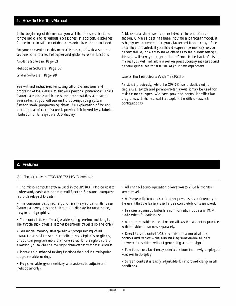
In the beginning of this manual you will find the specificationsfor the radio and its various accessories. In addition, guidelinesfor the initial installation of the accessories have been included.
For your convenience, this manual is arranged with a separatesections for airplane, helicopter and glider software functions:
Airplane Software: Page 21
Helicopter Software: Page 57
Glider Software: Page 99
You will find instructions for setting all of the functions andprograms of the XP8103 to suit your personal preferences. Thesefeatures are discussed in the same order that they appear onyour radio, as you will see on the accompanying systemfunction mode programming charts. An explanation of the useand purpose of each feature is provided, followed by a labeledillustration of its respective LCD display.
A blank data sheet has been included at the end of eachsection. Once all data has been input for a particular model, itis highly recommended that you also record it on a copy of thedata sheet provided. If you should experience memory loss orbattery failure, or want to make changes to the current settings,this step will save you a great deal of time. In the back of thismanual you will find information on precautionary measures andgeneral guidelines for safe use of your new equipment.
Use of the Instructions With This Radio
As stated previously, while the XP8103 has a dedicated, orsingle use, switch and potentiometer layout, it may be used formultiple model types. We have provided control identificationdiagrams with the manual that explain the different switchconfigurations.
1. How To Use This Manual
2. Features
2.1 Transmitter NET-G128FS/HS Computer
• The micro computer system used in the XP8103 is the easiest tounderstand, easiest to operate multi-function 8-channel computerradio developed to date.
• The computer designed, ergonomically styled transmitter casefeatures a newly designed, large LCD display for outstanding,easy-to-read graphics.
• The control sticks offer adjustable spring tension and length.The throttle stick offers a ratchet for smooth travel (airplane only).
• Ten model memory storage allows programming of allcharacteristics of ten separate helicopters, airplanes or gliders,or you can program more than one set-up for a single aircraft,allowing you to change the flight characteristics for that aircraft.
• Increased number of mixing functions that include multi-pointprogrammable mixing.
• Programmable gyro sensitivity with automatic adjustment(helicopter only).
• All channel servo operation allows you to visually monitorservo travel.
• A five-year lithium back-up battery prevents loss of memory inthe event that the battery discharges completely or is removed.
• Features automatic fail-safe and information update in PCMmode when fail-safe is used.
• A programmable trainer function allows the student to practicewith individual channels separately.
• Direct Servo Control (DSC) permits operation of all thecontrols and servos while also making transferable all databetween transmitters without generating a radio signal.
• Functions are also directly selectable from the newly employedFunction List Display.
• Screen contrast is easily adjustable for improved clarity in allconditions.

XP8103 9
NER-649S (PCM Systems)
• This is a high performance PCM-FM single conversion receiverwith 10 KHz super narrow band ABC&W circuitry.
• The latest “S” type Central Processing Unit (CPU) is used in thePCM receiver. The new NER-649S offers the highest resolutionavailable in any receiver.
• A narrow band ceramic filter for high signal selectivity alsoassists in rejecting cross modulation from other common radiofrequencies (e.g., R/C transmitters, local paging systems). It hasthe highest degree of resistance to electro-mechanical “noise” toimprove signal reception.
• This receiver features Direct Servo Control (DSC) permitscontrol of surfaces without radio frequency output.
• The receiver has low current consumption.
• 3-point gold plated connectors allow increased conductivity.
NER-549 (FM Systems)
• The NER-549 is a high performance FM single conversionreceiver with 10 KHz super-narrow band ABC&W circuitry.
• A narrow band ceramic filter for high signal selectivity assistsin rejecting cross modulations from other common radiofrequencies (e.g., R/C transmitters, local paging systems).
• This receiver features Direct Servo Control (DSC) for control ofsurfaces without radio frequency output.
• The receiver has low current consumption.
• 3-point gold plated connectors allow increased conductivity.
2.3 Servo Features
2.2 Receiver
507 Servo
• A zero deadband amplifier insures accurate neutral centering.
• The 507 has low current drain.
• An indirect drive feedback potentiometer gives additionalprotection from vibration.
• Redesigned features include SMT (Surface Mount Technology)circuitry.
• The 507 features a 3-pole ferrite cored motor.
517 Servo
• The 517 features a ball bearing output shaft for precisemovement of your aircraft’s control outputs.
• A zero deadband amplifier insures accurate neutral centering.
• The 517 has low current drain.
• An indirect drive feedback potentiometer gives additionalprotection from vibration.
• Includes SMT (Surface Mount Technology) circuitry.
• The 517 features a 3-pole ferrite cored motor.
531 Servo
• The 531 features a ball bearing output shaft for precisemovement of your aircraft’s control outputs.
• A zero deadband high performance amplifier insures accurateneutral centering and high torque (51oz./in.) with a speed of.23 sec/60°.
• The 531 has low current drain.
• An indirect drive feedback potentiometer gives additionalprotection from vibration.
• Includes SMT (Surface Mount Technology) Circuitry.
• The 531 features a 3-pole ferrite cored motor.

XP8103 10
3. Component Specifications
3.1 System Specifications (Air/Heli)
Aircraft Helicopter
System Name XP-8103A XP-8103H
Transmitter Body NET-G128FS NET-G128HS
Transmitter RF Module NET-J72P / NET-J50P / NET-J53P NET-J72P / NET-J50P / NET-J53P
Receiver NER-649S (PCM) NER-649S (PCM)NER-549 (FM) NER-549 (FM)
Charger NEC-221 NEC-222
Airborne Battery 4N-600 (flat) 4N-1000 (Flat)
Servos NES-507x4 NES-517x4 NES-517x5 NES-531x5(FM Only) (PCM Only) (FM only) (PCM Only)
Accessories Deluxe Switch Deluxe Switch Deluxe Switch Deluxe Switch12" ALIE Ext. 12" AILE Ext. 12" AILE Ext 12" AILE Ext.Charge Jack Charge Jack Charge Jack Charge JackServo Accys Servo Accys Servo Accys Servo AccysHex Wrench Hex Wrench Hex Wrench Charge JackInstruction Instruction Instruction InstructionManual Manual Manual Manual
3.2 Transmitter Specifications (Air/Heli)
Aircraft Helicopter
Model Number NET-G128FS NET-G128HS
Encoder 8-Channel Computer System 8-Channel Computer System
RF Module 50/53/72MHz 50/53/72MHz
Modulation PCM (S or Z) or PPM PCM (S or Z) or PPM
Output Power Approximately 750mw Approximately 750mw
Current Drain 200mA (70mA with DSC) 200mA (70mA with DSC)
Power Source 1.2Vx8 NiCad (9.6v) 550 mAh 1.2Vx8 NiCad (9.6v) 550 mAh
Output Pulse 1000-2000 (1500 Neutral) 1000-2000 (1500 Neutral)
XP8103 11
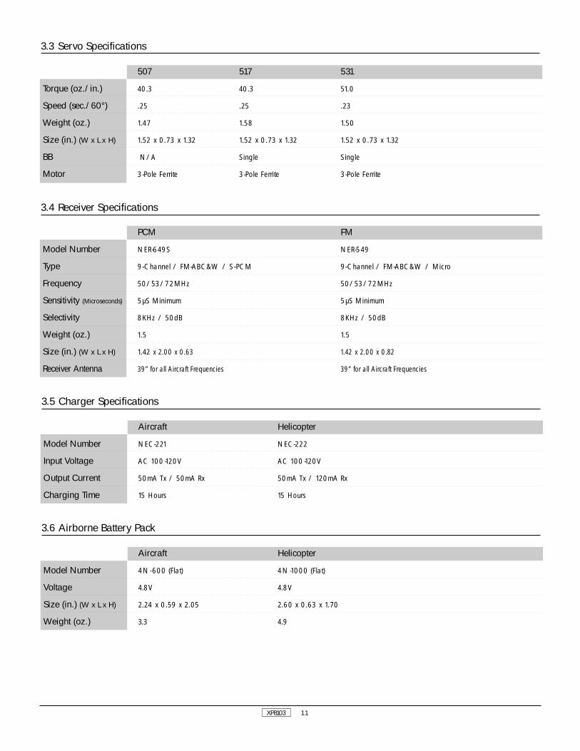
3.3 Servo Specifications
3.4 Receiver Specifications
3.5 Charger Specifications
Aircraft Helicopter
Model Number NEC-221 NEC-222
Input Voltage AC 100 -120V AC 100 -120V
Output Current 50mA Tx / 50mA Rx 50mA Tx / 120mA Rx
Charging Time 15 Hours 15 Hours
3.6 Airborne Battery Pack
Aircraft Helicopter
Model Number 4N-600 (Flat) 4N-1000 (Flat)
Voltage 4.8V 4.8V
Size (in.) (W x L x H) 2.24 x 0.59 x 2.05 2.60 x 0.63 x 1.70
Weight (oz.) 3.3 4.9
PCM FM
Model Number NER-649S NER-549
Type 9-Channel / FM-ABC&W / S-PCM 9-Channel / FM-ABC&W / Micro
Frequency 50/53/72MHz 50/53/72MHz
Sensitivity (Microseconds) 5µS Minimum 5µS Minimum
Selectivity 8KHz / 50dB 8KHz / 50dB
Weight (oz.) 1.5 1.5
Size (in.) (W x L x H) 1.42 x 2.00 x 0.63 1.42 x 2.00 x 0.82
Receiver Antenna 39” for all Aircraft Frequencies 39” for all Aircraft Frequencies
507 517 531
Torque (oz./in.) 40.3 40.3 51.0
Speed (sec./60°) .25 .25 .23
Weight (oz.) 1.47 1.58 1.50
Size (in.) (W x L x H) 1.52 x 0.73 x 1.32 1.52 x 0.73 x 1.32 1.52 x 0.73 x 1.32
BB N/A Single Single
Motor 3-Pole Ferrite 3-Pole Ferrite 3-Pole Ferrite

XP8103 12

XP8103 13
II. Common Features
14
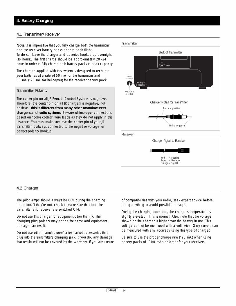
Note: It is imperative that you fully charge both the transmitterand the receiver battery packs prior to each flight. To do so, leave the charger and batteries hooked up overnight(16 hours). The first charge should be approximately 20–24hours in order to fully charge both battery packs to peak capacity.
The charger supplied with this system is designed to rechargeyour batteries at a rate of 50 mA for the transmitter and 50 mA (120 mA for helicopter) for the receiver battery pack.
Transmitter Polarity
The center pin on all JR Remote Control Systems is negative.Therefore, the center pin on all JR chargers is negative, notpositive. This is different from many other manufacturers’chargers and radio systems. Beware of improper connectionsbased on “color coded” wire leads as they do not apply in thisinstance. You must make sure that the center pin of your JRtransmitter is always connected to the negative voltage forcorrect polarity hookup.
XP8103
4. Battery Charging
4.1 Transmitter/Receiver
4.2 Charger
The pilot lamps should always be ON during the chargingoperation. If they’re not, check to make sure that both thetransmitter and receiver are switched OFF.
Do not use this charger for equipment other than JR. Thecharging plug polarity may not be the same and equipmentdamage can result.
Do not use other manufacturers’ after-market accessories thatplug into the transmitter’s charging jack. If you do, any damagethat results will not be covered by the warranty. If you are unsure
of compatibilities with your radio, seek expert advice beforedoing anything to avoid possible damage.
During the charging operation, the charger’s temperature isslightly elevated. This is normal. Also, note that the voltageshown on the charger is higher than the battery in use. Thisvoltage cannot be measured with a voltmeter. Only current canbe measured with any accuracy using this type of charger.
Be sure to use the proper charge rate (120 mA) when usingbattery packs of 1000 mAh or larger for your receivers.
D.S.C
TRAINER
CHARGE
(–) (+)
Center pinis negative
Outside ispositive
Red to negative
Black to positive
Red = PositiveBrown = NegativeOrange = Signal
Back of Transmitter
Charger Pigtail for Transmitter
Charger Pigtail to Receiver
Transmitter
Receiver

Elevator Tension Screw
Aileron Tension Screw
Throttle Tension Screw
Rudder Tension Screw
15
The XP8103 allows you to adjust the control sticks’ length.
To adjust the stick length, use the 2 mm Allen wrench (suppliedwith your XP8103 transmitter) to unlock the set screw.
Note: Turn the wrench counterclockwise to loosen the screw.Then, turn the stick clockwise to shorten or counterclockwise tolengthen.
After the control stick length has been adjusted to suit your flyingstyle, tighten the 2 mm set screw.
If you desire longer sticks, JR offers a thicker stick (JRPA047) thatis approximately one inch longer than the standard stick. Thisstick, crafted from bar stock aluminum, is available at your localJR dealer.
Remove the transmitter RF module, Nicad battery, and six (6)transmitter back cover screws. Remove the transmitter back,being careful not to bend or damage the RF module pins. Adjusteach screw for the desired tension (counterclockwise to loosen
stick feel, clockwise to tighten stick feel). When adjusting thethrottle ratchet tension, make sure the adjusting screw does nottouch the PC board after the adjustment is complete.
XP8103
5.1 Control Stick Length Adjustment
5.2 Control Stick Tension Adjustment
Loosen
Tighten
5. General Information
16XP8103
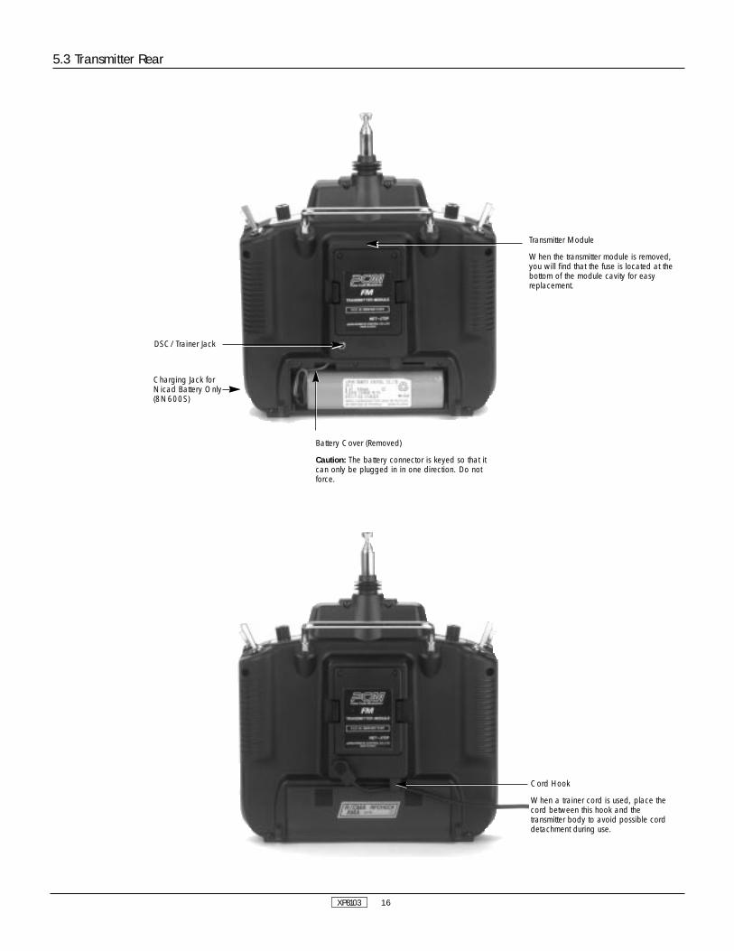
5.3 Transmitter Rear
Cord Hook
When a trainer cord is used, place thecord between this hook and thetransmitter body to avoid possible corddetachment during use.
Transmitter Module
When the transmitter module is removed,you will find that the fuse is located at thebottom of the module cavity for easyreplacement.
DSC/Trainer Jack
Charging Jack forNicad Battery Only(8N600S)
Battery Cover (Removed)
Caution: The battery connector is keyed so that itcan only be plugged in in one direction. Do notforce.

XP8103 17
For proper DSC hook up and operation:
1. Leave the transmitter power switch in the OFF position. Thetransmitter will not transmit any radio frequency (RF) in thisposition.
2. Plug the DSC cord (optional) into the DSC port in the rear ofthe transmitter.
3. The encoder section of the transmitter will now beoperational and the LCD display will be lit.
4. Plug the other end of the DSC cord into the receiver chargereceptacle. Turn the switch harness to the ON position.
Note: The DSC function will only operate with the JRPA001Deluxe Switch Harness, or the JRPA004 Charge Switch.
When you install the charging jack, be sure to hook thecharging jack receptacle securely into the switch harness chargecord.
Why you should use the DSC function:
1. The DSC enables you to check the control surfaces of yourairplanes without drawing the fully operational 200 mAh fromyour transmitter battery pack. Instead, you will only draw 70mAh when using the DSC function.
2. The DSC function allows you to make final adjustments toyour airplane without transmitting any radio signals. Therefore, ifanother pilot is flying on your frequency, you can still adjust yourairplane and not interfere with the other pilot’s aircraft.
Note: Under no circumstances should you attempt to fly yourairplane with the DSC cord plugged in! This function is forbench checking your airplane only.
5.4 DSC Cord
An eyelet is provided on the face of the XP8103 transmitterwhich allows you to connect a neck strap (JRPA023). This hookhas been positioned so that your transmitter has the best possiblebalance when you use the neck strap.
Note: Double check to ensure that the neck strap is securelyfastened to the transmitter.
5.5 Neck Strap Adjustment
An optional base loaded antenna is available for use with theXP8103 transmitter. It is considerably shorter than the standardantenna. However, the base loaded antenna cannot becollapsed for storage in the side of the transmitter. You must also
use an adaptor (JRPA156) to attach the antenna to your XP8103.The base loaded antenna (JRPA155) is made of a flexible coiland is covered with a soft plastic material. Your range will notbe affected when using the base loaded antenna.
5.6 Base Loaded Antenna
AB
C
A. Charge cord/DSC receptacleB. Switch harness leadC. Charge cord/DSC lead

XP8103 18
The XP8103 employs a plug-in module system for transmitterfrequency changes. If you want to change a frequency, you cansimply change the radio frequency (RF) module, commonlyreferred to as either an RF module or transmitter module. The JRmodules are universal for all modular frequency controlledsystems. In other words, if you currently own a modular JRsystem, you can use the RF module from your current system withthe XP8103.
The XP8103 can transmit in either Pulse Code Modulation (PCM)or in Pulse Position Modulation (PPM, commonly referred to asFM). Be certain to observe the following guidelines:
1. Do not operate your transmitter when another transmitter isusing the same frequency, regardless of whether the secondtransmitter is PCM, PPM (FM) or AM. You can never operatetwo transmitters on the same frequency simultaneously withoutcausing interference to both receivers and crashing both aircraft.
2. For operation of your XP8103 with additional receivers, youshould refer to the receiver compatibility chart. The chart islocated in the Modulation Select Section of this manual.(pg. 31)
Aircraft Only Frequencies
JR RF modules and receivers are available on 50, 53, and 72MHz frequencies in the United States for use with model aircraft.Employing 72 MHz frequencies does not require a specialoperators license from the Federal Communications Commission(FCC). However, the 50 and 53 MHz frequencies require thatyou carry a Technician II license.
• A chart for all available frequencies is located on page 142of this manual.
5.7 Frequency Notes/Aircraft Only Frequencies
5.8 Lithium Battery Indicator/Backup Error Display
Lithium Battery Indicator
If the voltage level of the lithium battery drops below anacceptable level (2.2v), an “L” will appear and flash to the leftof the model number. This indicates that the lithium battery will
no longer maintain program memory if the main battery isdisconnected. When the flashing “L” appears on the screen, thesystem should be sent to the JR/Horizon Service Center for alithium battery replacement.
Alarm and Backup Error Display
All pre-programmed data is protected by a five-year lithiumbattery that guards against main transmitter battery failure.Should the lithium battery fail, the display will indicate 1 backup error regardless of the position of the ON/OFF switch. Ifthis occurs, it will be necessary to replace the battery andreprogram all data. All transmitter programs will return to thefactory default setting, and the data you have input will be lost.
When it becomes necessary to replace the lithium back-upbattery, contact the JR/Horizon Service Center. Due to thepossibility of extensive damage caused by improper removal orreplacement, only the JR/Horizon Service Center is authorizedto make the change.
JR/Horizon Service Center4105 Fieldstone RoadChampaign, IL 61821
"L" indicateslithium batteryneeds to bereplaced

XP8103 19
5.9 Screen Contrast Adjustment
The screen contrast adjustment feature of the XP8103 allows theuser to select the proper tint of the screen for improved clarityand visibility in all weather conditions and temperatures.
To increase the contrast (darken the screen), simply turn the
power switch ON and press the SEL and DATA + keyssimultaneously. To decrease the contrast (lighten the screen),press the SEL and DATA - keys simultaneously.
5.10 Installation Requirements
It is extremely important that your radio system be correctlyinstalled in your model. Here are a few suggestions on theinstallation of your JR equipment.
1. Wrap the receiver in protective foam rubber that is no lessthan 3/8 inch thick. Secure the foam to the receiver with #64rubber bands. This protects the receiver in the event of a crashor a very hard landing.
2. The servos should be mounted using rubber grommets andbrass bushings to isolate them from vibration. Do not over-tightenthe mounting screws — this will negate the vibration absorptioneffect of the rubber grommets. The diagram at left will assist youin properly mounting your servo.
The brass bushings are pushed from the bottom up in the rubbergrommets. When the servo screw is tightened securely, itprovides the proper security, as well as the proper vibrationisolation, for your servo.
3. The servos must be able to move freely over their entirerange of travel. Make sure that the control linkages do not bindor impede the movement of any of the servos.
4. Mount all switches away from the engine exhaust and awayfrom any high vibration areas. Make sure each switch operatesfreely and is able to operate over its full travel.
5. Mount the receiver antenna firmly to the airplane to ensurethat it will not become entangled in the propeller or controlsurfaces.
Screw
Servo Mounting Tab
Brass Bushing
Rubber Grommet

XP8103 20

ACRO 21
III. Airplane Section

ACRO 22
1. Transmitter Controls
1.1 Control Identification and Location
Channel Assignment/Throttle ALT
Channel # TX Function Airplane Function1 Thro Throttle Channel2 Aile Aileron Channel3 Elev Elevator Channel4 Rudd Rudder Channel5 Gear Gear Channel6 Flap Auxillary 1 Channel (Flap)7 SPOI Auxillary 2 Channel (Spoiler)8 Aux 3 Auxillary 3 Channel
Throttle ALT
The Throttle ALT function makes the throttle stick trim active onlywhen the throttle stick is at less than half throttle. This gives easy,accurate idle adjustments without affecting the high throttleposition.
Throttle/Rudder Stick
Input Keys
Aileron Trim
Elevator Trim
Elevator/Aileron Stick
Antenna
Aux 3 Knob
Carrying Handle
LCD Display (Do Not Press)
Flap Knob
Aileron Dual Rate Switch
Rudder Dual Rate Switch
P. Mix Switch/Aux 2
Power Switch
Rudder Trim
Throttle Trim
Neck Strap Eyelet
Snap Roll/Timer/Trainer Switch
Aux 2 Knob
Elevator Dual Rate Switch
Gear Switch
Flap/Mixing Switch
Flaperon/Flap Trim Knob (Pot. 7)
Snap Roll/Timer/Trainer Switch
Crow Switch
Elevator Dual Rate Switch
Flap/Mixing Switch
Spoiler Trim
Spoiler/Rudder Stick
Neck Strap Eyelet
Rudder Trim
Power Switch
Input Keys
Aileron Trim
Aileron/Elevator StickElevator Trim
Flap Trim Knob (Pot. 6)
Aileron Dual Rate Switch
Rudder Dual Rate Switch
Mixing Switch
Carrying Handle
LCD Display –DO NOT PRESS
Antenna
Dual Flap Aileron Trim Knob (Pot. 5)
Reflex■-OffLaunch
Pitch Trim Knob
Trainer/Timer Switch
Invert Switch
Elevator Dual Rate Switch
Flight Mode Switch
Throttle Trim
Throttle/Rudder Stick
Neck Strap Eyelet
Rudder Trim
Power Switch
Input Keys
Aileron Trim
Aileron/Elevator StickElevator Trim
Hovering Throttle Knob
Aileron Dual Rate Switch
Rudder Dual Rate Switch
Throttle Hold Switch
Carrying Handle
LCD Display –DO NOT PRESS
Antenna
Hovering Pitch Knob
N-Normal Position1-Flight Mode 12-Flight Mode 2
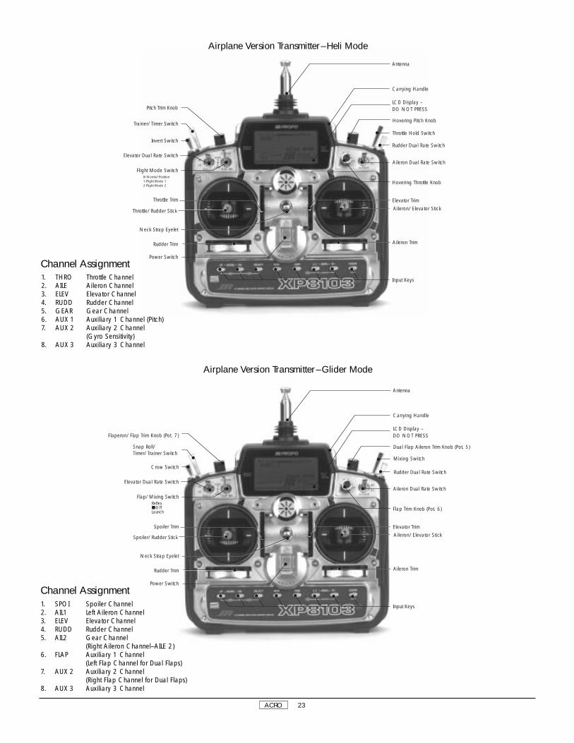
ACRO 23
Channel Assignment
Channel Assignment
Airplane Version Transmitter–Glider Mode
Airplane Version Transmitter–Heli Mode
1. SPOI Spoiler Channel 2. AIL1 Left Aileron Channel 3. ELEV Elevator Channel 4. RUDD Rudder Channel 5. AIL2 Gear Channel
(Right Aileron Channel–AILE 2)6. FLAP Auxiliary 1 Channel
(Left Flap Channel for Dual Flaps) 7. AUX 2 Auxiliary 2 Channel
(Right Flap Channel for Dual Flaps)8. AUX 3 Auxiliary 3 Channel
1. THRO Throttle Channel 2. AILE Aileron Channel 3. ELEV Elevator Channel 4. RUDD Rudder Channel 5. GEAR Gear Channel 6. AUX 1 Auxiliary 1 Channel (Pitch)7. AUX 2 Auxiliary 2 Channel
(Gyro Sensitivity)8. AUX 3 Auxiliary 3 Channel

ACRO 24
1.2 Connections
Aux Channel
Aux Channel
Spoiler Channel
Flap Channel
RetractGear Channel
Deluxe Switch Harness(JRPA001)
Charge Cord or DSCReceptacle(JRPA024)
72
NER-649SS-PCM Receiver
(JRPR649)PCM Version
NER-549SFM Receiver(JRPR549)FM Version
4N6004.8V 600mAh
JAPAN REMOTE CONTROL CO., LTD.
®
notused

ACRO 25
• You will hear a clicking (beeping) sound to confirm input hasbeen achieved.
• Except for the CLEAR key, the AUTO advance system (twospeed scrolling) is active when you continue pressing down ona key.
• The SEL keys or CH keys are used to scroll through, ormanipulate functions within a specific program or display.
2.1 Input Key Functions
Function Selection keys(press both keyssimultaneously to enter orexit the function mode)
Normal Display Screen
Press both keys simultaneouslyto access the system mode orfunction mode lists.
used for changing pages orindicated displays
used for channel changes in themodel set-up and function modes
Data Entry Keys
Up Key
Down Key Select Key Channel Key Increase Key Decrease Key
Clear Key
2.2 Normal Display
2. General Information
transmitter voltagemodel number
modulation typemodel name (whennames are entered)
integrated timer
SELECT L /+ R/- CLEAR

ACRO 26
2.2 Normal Display, cont.
DN SELECT CH CH CLEARUP
Press simultaneouslyto access the ListMode/System Set-Up Mode
Press Select andeither the + or - keyssimultaneously toadjust the contrast ofthe LCD display
Press the Clear keyto reset to factorysettingsPress the UP and DN keys
simultaneously to changeto Function Mode (withpower switch ON)
When timer function isactive, use CH key tostart/stop timer
Press the UP and DN keyssimultaneously and switch thepower from OFF to ON tochange the system to theSystem Set-Up Mode
To set the System Set-Up Mode, press the UP and DN keyssimultaneously and turn the power switch from OFF to ON.Functions are selectable by pressing either the DN or UP keys.Individual settings are explained later at each function. In thismode, servos are not activated, but operating signals are
transmitting (only when the Tx module is in place). However, useextra caution not to interfere with other frequencies. By pressingthe DN and UP keys simultaneously, you can return to the normaldisplay, which allows the servos to again operate.
3.1 System Set-Up Mode
[INFO-DISP]
↕
From the Normal Display, the following inputs can be made:
When setting various functions with the buttons shown below,start either in the Function Mode or the System Set-Up Mode.
3. System Set-Up Mode Functions
Pg. 28 Information Display
Pg. 29 Model Select and Copy
Pg. 29 Model Name Input
Pg. 30 Model Type Selection Function
Pg. 30 Data Reset
Pg. 31 Modulation Selection
Pg. 32 Data Transfer between traqnsmitters
Pg. 34 Wing Type Selection
Pg. 35 Spoiler Channel Input Selection
SYSTEM SET-UP MODE
Use either the UPor DN key to scrollthrough the menuand access theapplicable function

ACRO 27
From Normal Display, press the UP and DN keys simultaneouslyto enter the Function Mode. In this mode, by using the UP or DNkeys, the desired functions can be selected. When channelselection or an additional function change is desired, use theCH keys or SEL key. For example, Dual Rate Function is selectedand the elevator channel is displayed by pressing the UP keyonce; the function is changed to the next mode, Reverse Switch,but the channel is still displayed as elevator.
Function Mode Flowchart
Information pertaining to each function is explained on the pagenumber listed next to the function name. Functions will appearon the screen in the same order they are shown on the flowchart below:
Therefore, by scrolling through the program, you can adjusteach function related to the elevator channel quickly and easily.
To Access The Function Mode
1. Switch the power switch to the ON (upper) position.
2. Press the UP and DN keys simultaneously.
3. Use either the UP or DN keys to scroll through the menu andaccess the appropriate function.
3.2 Function Mode
Pg. 36 Dual Rate, Exponential
Pg. 38 Reverse Switch
Pg. 38 Sub-Trim
Pg. 39 Travel Adjust (end point adjustment)
Pg. 39 Elevator to Flap Mixing
Pg. 40 Aileron to Rudder Mixing
Pg. 41 Landing System
Pg. 42 Snap Roll
Pg. 44 Differential Aileron Mixing (only if flaperon orelevons mixing is active)
Pg. 45 Trim Offset Memory
Pg. 46 Flap Knob Operating Value Adjustment
Pg. 47 Programmable Mixing 1
Pg. 47 Programmable Mixing 2
Pg. 47 Programmable Mixing 3
Pg. 47 Programmable Mixing 4
Pg. 47 Programmable Mixing 5
Pg. 47 Programmable Mixing 6
Pg. 50 Fail-Safe/Hold (PCM Only)
Pg. 52 Trainer
Pg. 54 Timer
Pg. 55 Servo Output Values
Use either the UPor DN key to scrollthrough the menuand access theapplicable function
ACRO 28
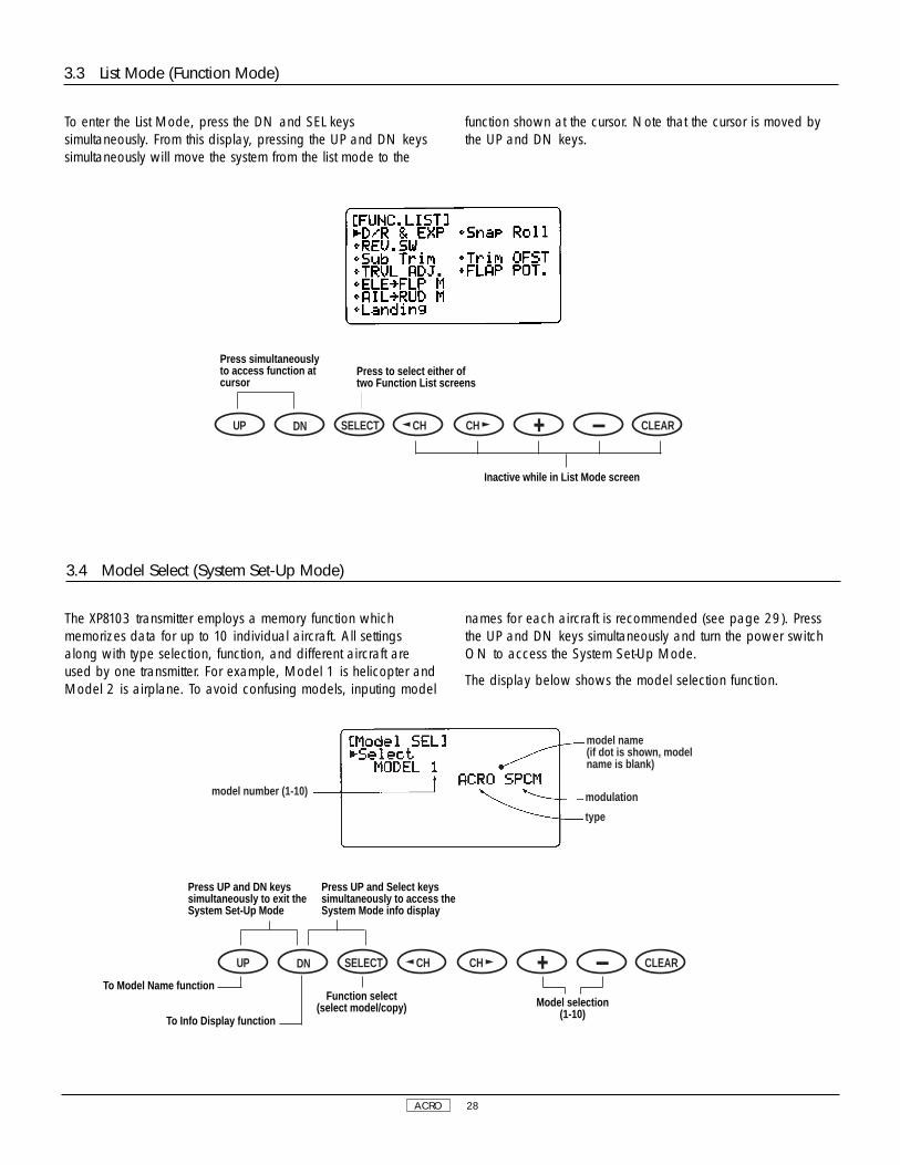
3.4 Model Select (System Set-Up Mode)
The XP8103 transmitter employs a memory function whichmemorizes data for up to 10 individual aircraft. All settingsalong with type selection, function, and different aircraft areused by one transmitter. For example, Model 1 is helicopter andModel 2 is airplane. To avoid confusing models, inputing model
names for each aircraft is recommended (see page 29). Pressthe UP and DN keys simultaneously and turn the power switchON to access the System Set-Up Mode.
The display below shows the model selection function.
model name(if dot is shown, modelname is blank)
modulation
type
model number (1-10)
To enter the List Mode, press the DN and SEL keyssimultaneously. From this display, pressing the UP and DN keyssimultaneously will move the system from the list mode to the
function shown at the cursor. Note that the cursor is moved bythe UP and DN keys.
3.3 List Mode (Function Mode)
DN SELECT CH CH CLEARUP
DN SELECT CH CH CLEARUP
Press simultaneouslyto access function atcursor
Press UP and DN keyssimultaneously to exit theSystem Set-Up Mode
To Model Name function
To Info Display function
Function select (select model/copy) Model selection
(1-10)
Press UP and Select keyssimultaneously to access theSystem Mode info display
Press to select either oftwo Function List screens
Inactive while in List Mode screen

ACRO 29
3.5 Copy Select Function (System Set-Up Mode)
The Copy Select Function enables you to copy all of the settingsof your current model to another memory (model number) within
the same transmitter. This is very useful when setting up oneaircraft several different ways.
model names(if dot is shown, modelname is blank)
existing modelnumber
model number to betransferred to.
3.6 Model Names (System Set-Up Mode)
This function is used to input model names individually. Eachmodel’s name is displayed in the normal screen automatically.when that model is selected. To avoid confusing models,inputing model names is recommended. You can input a
maximum of 8 characters for each model name.
In the System Set-Up Mode, select the Model Name Functionusing the UP or DN key. Once selected, simultaneously press theUP and DN keys to access.
model number
modulation
model type
letter position beinginputed
DN SELECT CH CH CLEARUP
Press UP and DN keyssimultaneously to exit theSystem Set-Up Mode
Press the Select key toaccess the copy functionin Model Select mode
To Model Name function
To Spoiler Channel inputselection function
Function select (select model/copy) Model selection —
use to select modelto be copied to
Activate copyfunction
DN SELECT CH CH CLEARUP
Press UP and DN keyssimultaneously to exit theSystem Set-Up Mode
Press the DN and Select keyssimultaneously to access theSystem Mode info display
(8 characters)
To Model Type Selectionfunction
To Model Select/Copyfunction
Press to changeinput letter at arrow
Press to changeinput letter arrowposition
Changes input letterto blank space onlywhere arrow islocated
ACRO 30
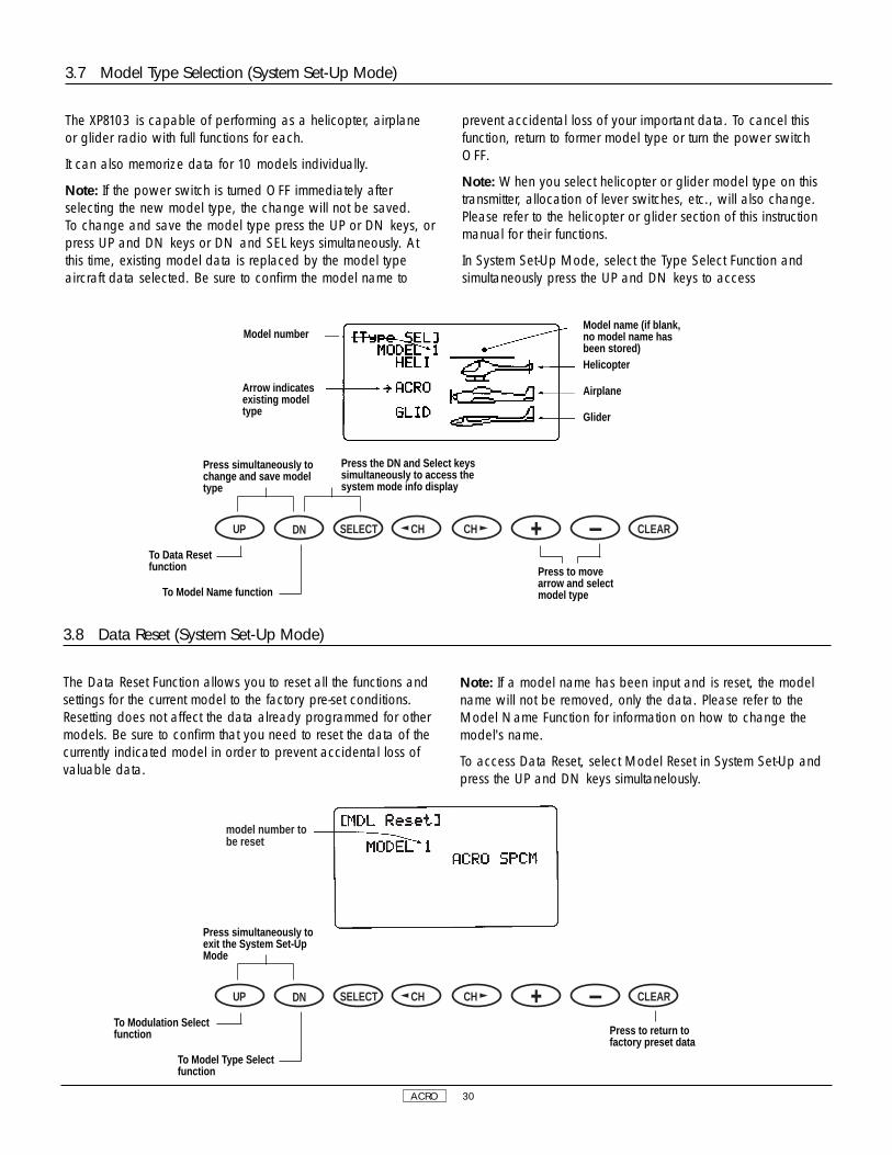
3.8 Data Reset (System Set-Up Mode)
The Data Reset Function allows you to reset all the functions andsettings for the current model to the factory pre-set conditions.Resetting does not affect the data already programmed for othermodels. Be sure to confirm that you need to reset the data of thecurrently indicated model in order to prevent accidental loss ofvaluable data.
Note: If a model name has been input and is reset, the modelname will not be removed, only the data. Please refer to theModel Name Function for information on how to change themodel's name.
To access Data Reset, select Model Reset in System Set-Up andpress the UP and DN keys simultanelously.
model number tobe reset
3.7 Model Type Selection (System Set-Up Mode)
The XP8103 is capable of performing as a helicopter, airplaneor glider radio with full functions for each.
It can also memorize data for 10 models individually.
Note: If the power switch is turned OFF immediately afterselecting the new model type, the change will not be saved.To change and save the model type press the UP or DN keys, orpress UP and DN keys or DN and SEL keys simultaneously. Atthis time, existing model data is replaced by the model typeaircraft data selected. Be sure to confirm the model name to
prevent accidental loss of your important data. To cancel thisfunction, return to former model type or turn the power switchOFF.
Note: When you select helicopter or glider model type on thistransmitter, allocation of lever switches, etc., will also change.Please refer to the helicopter or glider section of this instructionmanual for their functions.
In System Set-Up Mode, select the Type Select Function andsimultaneously press the UP and DN keys to access
DN SELECT CH CH CLEARUP
Press simultaneously tochange and save modeltype
Press the DN and Select keyssimultaneously to access thesystem mode info display
To Data Resetfunction
Model numberModel name (if blank,no model name hasbeen stored)Helicopter
Airplane
Glider
Arrow indicatesexisting modeltype
To Model Name function
Press to movearrow and selectmodel type
DN SELECT CH CH CLEARUP
Press simultaneously toexit the System Set-UpMode
To Modulation Selectfunction
To Model Type Selectfunction
Press to return tofactory preset data
ACRO 31
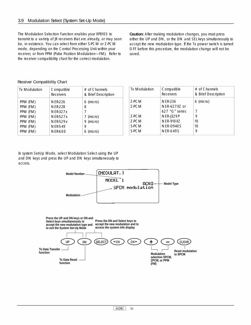
In system Set-Up Mode, select Modulation Select using the UPand DN keys and press the UP and DN keys simultaneously toaccess.
3.9 Modulation Select (System Set-Up Mode)
The Modulation Selection Function enables your XP8103 totransmit to a variety of JR receivers that are already, or may soonbe, in existence. You can select from either S-PCM or Z-PCMmode, depending on the Central Processing Unit within yourreceiver, or from PPM (Pulse Position Modulation—FM). Refer tothe receiver compatibility chart for the correct modulation.
Caution: After making modulation changes, you must presseither the UP and DN, or the DN and SEL keys simultaneously toaccept the new modulation type. If the Tx power switch is turnedOFF before this procedure, the modulation change will not besaved.
Tx Modulation Compatible # of Channels Receivers & Brief Description
PPM (FM) NER-226 6 (micro)PPM (FM) NER-228 8PPM (FM) NER-327x 7PPM (FM) NER-527x 7 (micro)PPM (FM) NER-529x 9 (micro)PPM (FM) NER-549 9PPM (FM) NER-600 6 (micro)
Tx Modulation Compatible # of Channels Receivers & Brief Description
Z-PCM NER-236 6 (micro)Z-PCM NER-627XZ or
627 “G” series 7Z-PCM NER- J329P 9Z-PCM NER-910XZ 10S-PCM NER-D940S 10S-PCM NER-649S 9
Receiver Compatibility Chart
Modulationselection SPCM,ZPCM, or PPM(FM)
DN SELECT CH CH CLEARUP
Press the UP and DN keys or DN andSelect keys simultaneously toaccept the new modutation type andto exit the System Set-Up Mode
Press the DN and Select keys toaccept the new modulation and toaccess the system info display
To Data Transferfunction
Model Type
Model Number
Modulation
To Data Resetfunction
Reset modulationto SPCM

ACRO 32
CLR start transmitting
transmitting counter(0-100%)
make sure that the receivingmode transmitter (Tx to beprogrammed) is in the stand-bycondition.
Transfer Procedure
1. Select the model number to be transferred (transmitting modeside) through the model select function. (See page 28 forinformation on Model Select Function.)
2. Both transmitters: With the power switches OFF, press the UPand DN keys simultaneously while inserting the trainer cord intothe DSC jacks of both transmitters.
3. Both transmitters: Select the Transfer Fuction by pressing theUP or DN key. Then simultaneously press the UP and DN keys toenter the Transfer Function.
4. Receiving mode transmitter (Tx to be programmed): Press theSelect key until the screen reads "Receive." Select the receivingmodel number by pressing the + or - keys. Next, press the CLRkey to activate the receiving stand-by mode.
5. Transmitting mode transmitter (Tx with program to betransferred): Press the CLR key to start transmitting data. Bothtransmitters will indicate [End ok!] display when the transmittingis complete.
3.10 Data Transfer (System Set-Up Mode)
This function is used to transfer all existing memorized data for amodel from one XP8103 transmitter to another XP8103 transmitter.
Use the + and - keys to select models to be transferred andactivate by pressing the CLR key.
To avoid the loss of important data, re-confirm model nameswhen transferring.
Caution: Please use special caution when copy function isactivated as existing data is replaced with new data.
Caution: When the battery alarm is activated (battery low), thecopy function is not operational.
Transmitting mode
Model number
Display indicates DSC cord isnot connected, or Tx powerswitch is on/off
Press + or -keys to selectmodels to betransferred
Press + or -keys to selectthe receivingmodel number
DN SELECT CH CH CLEARUP
Press the UP and DN keyssimultaneously to enter/exit theSystem Set-Up Mode
Press the DN and Select keyssimultaneously to access theSystem Mode info display
To Wing Typeselection function
To Modulationselect function
SelectTransmitting/Receiving Mode
Press to starttransmittingdata
DN SELECT CH CH CLEARUP
To Wing Typeselection function
To Modulationselect function
Transmitting/Receiving Modeselect
ACRO 33
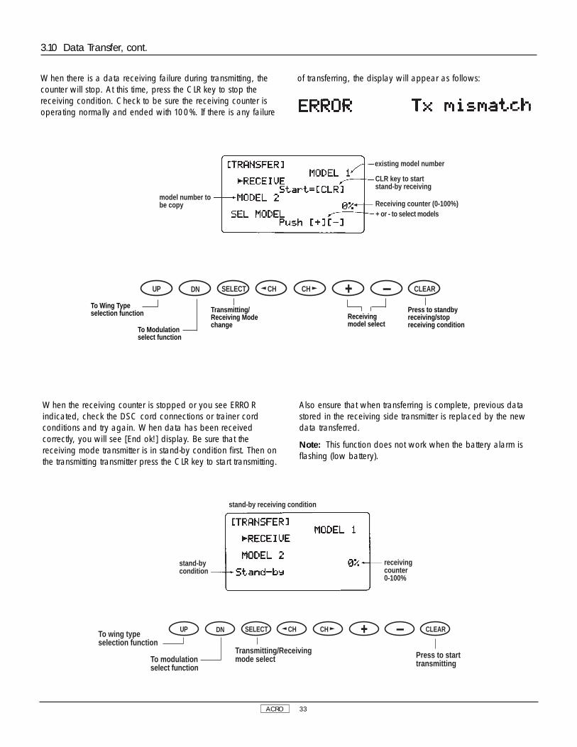
existing model number
CLR key to startstand-by receiving
+ or - to select models
model number tobe copy Receiving counter (0-100%)
When there is a data receiving failure during transmitting, thecounter will stop. At this time, press the CLR key to stop thereceiving condition. Check to be sure the receiving counter isoperating normally and ended with 100%. If there is any failure
of transferring, the display will appear as follows:
3.10 Data Transfer, cont.
stand-bycondition
receivingcounter0-100%
stand-by receiving condition
To wing typeselection function
To modulationselect function
DN SELECT CH CH CLEARUP
Transmitting/Receivingmode select Press to start
transmitting
When the receiving counter is stopped or you see ERRORindicated, check the DSC cord connections or trainer cordconditions and try again. When data has been receivedcorrectly, you will see [End ok!] display. Be sure that thereceiving mode transmitter is in stand-by condition first. Then onthe transmitting transmitter press the CLR key to start transmitting.
Also ensure that when transferring is complete, previous datastored in the receiving side transmitter is replaced by the newdata transferred.
Note: This function does not work when the battery alarm isflashing (low battery).
Receivingmodel select
Press to standbyreceiving/stopreceiving condition
DN SELECT CH CH CLEARUP
To Wing Typeselection function
To Modulationselect function
Transmitting/Receiving Modechange
ACRO 34
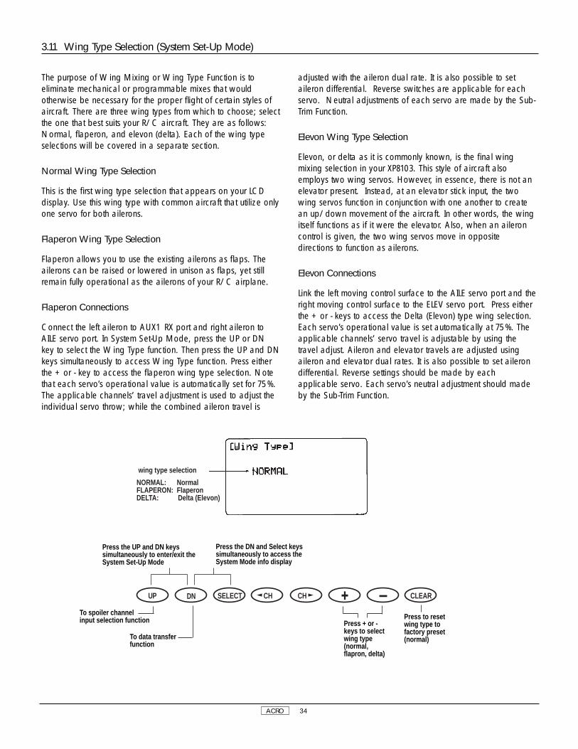
wing type selection
NORMAL: NormalFLAPERON: FlaperonDELTA: Delta (Elevon)
The purpose of Wing Mixing or Wing Type Function is toeliminate mechanical or programmable mixes that wouldotherwise be necessary for the proper flight of certain styles ofaircraft. There are three wing types from which to choose; selectthe one that best suits your R/C aircraft. They are as follows:Normal, flaperon, and elevon (delta). Each of the wing typeselections will be covered in a separate section.
Normal Wing Type Selection
This is the first wing type selection that appears on your LCDdisplay. Use this wing type with common aircraft that utilize onlyone servo for both ailerons.
Flaperon Wing Type Selection
Flaperon allows you to use the existing ailerons as flaps. Theailerons can be raised or lowered in unison as flaps, yet stillremain fully operational as the ailerons of your R/C airplane.
Flaperon Connections
Connect the left aileron to AUX1 RX port and right aileron toAILE servo port. In System Set-Up Mode, press the UP or DNkey to select the Wing Type function. Then press the UP and DNkeys simultaneously to access Wing Type function. Press eitherthe + or - key to access the flaperon wing type selection. Notethat each servo’s operational value is automatically set for 75%.The applicable channels’ travel adjustment is used to adjust theindividual servo throw; while the combined aileron travel is
adjusted with the aileron dual rate. It is also possible to setaileron differential. Reverse switches are applicable for eachservo. Neutral adjustments of each servo are made by the Sub-Trim Function.
Elevon Wing Type Selection
Elevon, or delta as it is commonly known, is the final wingmixing selection in your XP8103. This style of aircraft alsoemploys two wing servos. However, in essence, there is not anelevator present. Instead, at an elevator stick input, the twowing servos function in conjunction with one another to createan up/down movement of the aircraft. In other words, the wingitself functions as if it were the elevator. Also, when an aileroncontrol is given, the two wing servos move in oppositedirections to function as ailerons.
Elevon Connections
Link the left moving control surface to the AILE servo port and theright moving control surface to the ELEV servo port. Press eitherthe + or - keys to access the Delta (Elevon) type wing selection.Each servo’s operational value is set automatically at 75%. Theapplicable channels’ servo travel is adjustable by using thetravel adjust. Aileron and elevator travels are adjusted usingaileron and elevator dual rates. It is also possible to set ailerondifferential. Reverse settings should be made by eachapplicable servo. Each servo’s neutral adjustment should madeby the Sub-Trim Function.
3.11 Wing Type Selection (System Set-Up Mode)
Press the UP and DN keyssimultaneously to enter/exit theSystem Set-Up Mode
Press the DN and Select keyssimultaneously to access theSystem Mode info display
Press + or -keys to selectwing type(normal,flapron, delta)
Press to resetwing type tofactory preset(normal)
DN SELECT CH CH CLEARUP
To spoiler channelinput selection function
To data transferfunction

ACRO 35
3.11 Wing Type Selection (System Set-Up Mode), cont.
AILE servo port(right aileron)
ELEV servo port(right aileron)
AUX 1 servo port(left aileron)
AILE servo port(left aileron)
Flaperon Wing Type Connections Elevon Wing Type Connections
The purpose of the Spoiler Channel Input Selection Function is toassign the activation device for the AUX2 channel. The knobprovides proportional control, while the switch allows ON/OFFfunction of the AUX2 channel.
In System Set-Up Mode, select Spoiler Function and access bypressing the UP and DN keys simultaneously.
3.12 Spoiler Channel Input Selection (System Set-Up Mode)
spoiler channel input displayAUX2 POT: AUX2 knobMIX SW: Mixing switch
Note that individual spoileroperation is inhibited whenspoiler is coupled for automaticlanding attitude.
Press the UP and DN keyssimultaneously to enter/exit theSystem Set-Up Mode
Press the DN and Select keyssimultaneously to access theSystem Mode info display
Input Selection(Aux 2 Pot/Mix SW)
Press to returnspoiler channelinput to preset(Aux 2 knob)
DN SELECT CH CH CLEARUP
To Model TypeSelection function
To Wing TypeSelection function

ACRO 36
Dual rates are available for the aileron, elevator and rudderchannels of your R/C airplane. The amount of travel isadjustable from 0-125%; exponential is adjustable from 0% (LIN)to 100% in 1% increments. The factory setting, or default value,for both the 0 and 1 switch positions is 100%. Either switchposition may be selected as the low or high rate by placing theswitch in the desired position and adjusting the valueaccordingly. There is also an automatic rudder dual rate settingfor the rudder.
Dual rates can be defined as the ability to vary the travel or
throw rate of a servo from a switch. Due to differing travel rates,you will find that the sensitivity of the control either increases ordecreases accordingly. A higher rate, or travel, yields a higheroverall sensitivity. You may find it easier to think of the Dual RateFunction as double-rated or half-rates.
The Dual Rate Function works in conjunction with the ExponentialFunction to allow you to precisely tailor your control throws.
In Function Mode, use the UP or DN key to select Dual Rate andaccess by pressing the UP and DN keys simultaneously.
AILE AileronELEV ElevatorRUDD RudderAUTO auto dual rateRUDD auto exponential
Dual rate switch position
4.1 Dual Rate, Exponential (Function Mode)
4. Function Mode Functions
Press the UP and DN keyssimultaneously to enter/exitthe Function Mode
Press the DN and Select keyssimultaneously to access theFunction Mode list display
Increase ordecrease DualRate Value
Channel Selection(Aile, Elev, Rudd,
Auto Rudd)
Reset Dual RateValue to 100%
DN SELECT CH CH CLEARUP
To Reverse Switchfunction Function Select
(dual rate orexponential)To Servo Output
Indicator

ACRO 37
Setting conditionINH: inhibit (funtion off)ACT: Active (function on)
When the Automatic Rudder Dual Rate Function is active, thethrottle stick position automatically switches among the rudderdual rates that you have selected in the Dual Rate Function. Thismeans that, as you advance or pull back the throttle stick, therudder travel rates automatically change. When the throttle stickis moved in any position from low to approximately 70% of fulltravel, the 0 rudder rate is active; once the throttle is fullyadvanced, the 1 rudder travel will automatically return.
Once the Automatic Dual Rate Function has been activated, theword AUTO will appear on the rudder DR/EXP screen.
Automatic Rudder Dual Rate Setting
Suggested rudder dual rate settings are as follows:
Dual Rate Switch Position
0 Position (maximum servo travel)
1 Position (minimum servo travel)
Example: 0 position value is set to 100%; 1 position value is setto 80%.
Note: The Rudder Dual Rate Switch must be in the rearward (0)position for the auto dual rate to function.
To enter the Auto Dual Rate function, from the Dual Rate andExponential Rate function, press the CH key until AUTO RUDDappears. Press the + key to activate the Auto Rudder function.Next, adjust the Rudder Dual Rate as described in previoussection.
4.2 Automatic Dual Rate, Exponential (Function Mode)
Press the UP and DN keyssimultaneously to enter/exitthe Function Mode
Press the DN and Select keyssimultaneously to access theFunction Mode list display
Use + or - toactivate/inhibitAuto D/R
Channel Selection(Press to select
Auto Rudd)
Press to inihbitD/R
DN SELECT CH CH CLEARUP
To Reverse Switchfunction
To Servo OutputIndicator

ACRO 38
4.4 Sub-Trim Adjustment (Function Mode)
The Sub-Trim Adjustment Function allows you to electronicallyfine tune the centering of your servos. Individually adjustable forall eight channels, with a range of + or - 125% (+ or - 30degrees servo travel).
Caution: Do not use excessive sub-trim adjustments as it ispossible to overrun your servo's maximum travel.
In Function Mode, use the UP or DN key to select the ReverseSwitch function and access by pressing the UP and DN keyssimultaneously.
4.3 Reverse Switch (Function Mode)
The Reverse Switch is an electronic means of reversing the throw(direction) of a given channel (servo). All eight channels of theXP8103 offer reversible servo direction. This will ease set-upduring servo installation in your aircraft.
In Function Mode, use the UP or DN key to select the ReverseSwitch function and access by pressing the UP and DN keyssimultaneously.
Channel being programmedTHRO ThrottleAILE AileronELEV ElevatorRUDD RudderGEAR Retract landing gearFLAP Flap (Aux1)SPOI Spoiler (Aux2)AUX3 Extra channel (Aux3)
Press the UP and DN keyssimultaneously to enter/exitthe Function Mode
Press the DN and Select keyssimultaneously to access theFunction Mode List Display
Use + or - tochange
(normal/reverse)
Channel Selection(1-8)
Reset traveldirection tofactory preset(normal)
DN SELECT CH CH CLEARUPTo Sub-TrimAdjustment function
To Dual Rate/Exponential function
Press the UP and DN keyssimultaneously to enter/exitthe Function Mode
Press the DN and Select keyssimultaneously to access theFunction Mode List Display
Increase ordecrease
sub-trim value(L&R/U&D)
Channel Selection(press to
manipulate arrow)
Press to resetSub-trim value tofactory preset (0)
Press to displaychannels 1-4and 5-8(2 Screens)
DN SELECT CH CH CLEARUP
To Travel Adjustfunction
To Reverse Switchfunction
Sub-trim value(max±125)
Channel being programmedTHRO ThrottleAILE AileronELEV ElevatorRUDD RudderGEAR Retract landing gearFLAP Flap (Aux1)SPOI Spoiler (Aux2)AUX3 Extra channel (Aux3)
ACRO 39
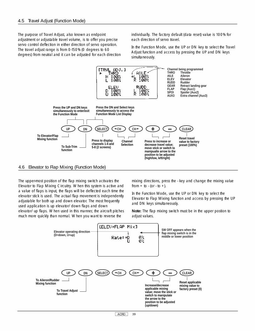
4.5 Travel Adjust (Function Mode)
The purpose of Travel Adjust, also known as endpointadjustment or adjustable travel volume, is to offer you preciseservo control deflection in either direction of servo operation.The travel adjust range is from 0-150% (0 degrees to 60degrees) from neutral and it can be adjusted for each direction
individually. The factory default (data reset) value is 100% foreach direction of servo travel.
In the Function Mode, use the UP or DN key to select the TravelAdjust function and access by pressing the UP and DN keyssimultaneously.
Channel being programmedTHRO ThrottleAILE AileronELEV ElevatorRUDD RudderGEAR Retract landing gearFLAP Flap (Aux1)SPOI Spoiler (Aux2)AUX3 Extra channel (Aux3)
4.6 Elevator to Flap Mixing (Function Mode)
The upper-most position of the flap mixing switch activates theElevator to Flap Mixing Circuitry. When this system is active anda value of flaps is input, the flaps will be deflected each time theelevator stick is used. The actual flap movement is independentlyadjustable for both up and down elevator. The most frequentlyused application is up elevator/down flaps and downelevator/up flaps. When used in this manner, the aircraft pitchesmuch more quickly than normal. When you want to reverse the
mixing directions, press the - key and change the mixing valuefrom + to - (or - to +).
In the Function Mode, use the UP or DN key to select theElevator to Flap Mixing function and access by pressing the UPand DN keys simultaneously.
Note: The flap mixing switch must be in the upper postion toadjust values.
Elevator operating direction(D=down, U=up)
SW OFF appears when theflap mixing switch is in themiddle or lower position
Press the UP and DN keyssimultaneously to enter/exitthe Function Mode
Press the DN and Select keyssimultaneously to access theFunction Mode List Display
Press to increase ordecrease travel value;move stick or switch tomanipualte arrow to theposition to be adjusted(high/low, left/right)
ChannelSelection
Reset travelvalue to factorypreset (100%)
DN SELECT CH CH CLEARUP
To Elevator/FlapMixing function
To Sub-Trimfunction
Press to displaychannels 1-4 and5-8 (2 screens)
Increase/decreaseapplicable mixingvalue; move the stick orswitch to manipulatethe arrow to theposition to be adjusted(up/down)
Reset applicablemixing value tofactory preset (0)
DN SELECT CH CH CLEARUP
To Aileron/RudderMixing function
To Travel Adjustfunction

ACRO 40
Press the CH key to selectthe function beingprogrammed
Mixing value ( ±125%)
On or Off mixing switchdisplay (refer to chartabove)
4.7 Aileron to Rudder Mixing (Function Mode)
This form of mixing is designed so that when input to the aileronstick is given, the rudder servo will also move, eliminating theneed to coordinate these controls manually.
When adjusting, if an opposite mixing direction of the rudderservo is required, simply press the + or - key and change themixing value from + to - or - to +. This will reverse the mixingdirection of the rudder from its original direction.
Mixing Operation and Switches
This mixing program can be turned ON/OFF by a switch. Theswitches that can be selected are shown on the chart at right,with their abbreviations as they appear on the screen and thecorresponding switch positions.
Switch Function
ON Mixing Always ON
MIX Switch ON/OFF Using Mixing Switch
Land Switch ON/OFF Using Landing Switch
ELE>F Switch ON/OFF Using Elevator to Flap Mixing
In the Function Mode, use the UP or DN key to select Aileron toRudder Mixing and access by pressing the UP and DN keyssimultaneously.
To adjust, move the arrow to SW with the CH key and select theneeded switch setting using either the + or - key.
Press the UP and DN keyssimultaneously to enter/exitthe Function Mode
Press the DN and Select keyssimultaneously to access theFunction Mode List Display
At Rate: Press toincrease or decreasemixing value ± 125%
At Switch:Press to change Switch Selection
Press tomanipulatearrow fromRate to SW:
At Rate:Press to set mixingvalue to factory preset(0%)
At Switch:Press to set switch tofactory preset (ON)
DN SELECT CH CH CLEARUP
To Landing FunctionSystem
To Elevator/FlapMixing function

ACRO 41
4.8 Landing System (Function Mode)
Channel indicatorELEV: Elevator landing valueFLAP: Flap landing valueSPOI: Spoiler coupling settingAUTO: Automatic landing setting
Indicate SW OFF when landingfunction is not selected
Servo travel value whenlanding function is selected
The purpose of the landing system is to set the aircraft in alanding attitude for more consistent landings. This isaccomplished by selecting values for the elevator, flap andspoiler — AUX 2 (if active) — to be activated when the landswitch is engaged. Note that the spoiler (AUX 2) can be mixedin with the elevator and flap landing attitudes, but only in thedeployed or retracted positions. The landing system can also beactivated by a preset position of the throttle stick. Refer to theAutomatic Landing Attitude Section for more information on howto select the preset throttle position.
Accessing and Utilizing the Landing System Feature
To access the landing system feature (refer to figure A):
1. Place the transmitter power switch in the ON (upperposition).
2. Press the UP and DN keys simultaneously to enter theFunction Mode.
3. Press either the UP or DN keys until “LANDING” appears inthe upper left portion of the LCD.
4. Press either the left or right CH key to position the cursor atthe desired function (i.e., ELEV, FLAP, SPOI, AUTO).
5. Press the + or - keys to set the value for flap and elevatortravel. The + key adds up flap/elevator and the - key addsdown flap/elevator. The input is adjustable from 0-250% for flapand 0-125% for elevator. This results in a flap input from 0 -60degrees and an elevator input from 0-30 degrees.
Spoiler Coupling
Auxiliary 2 serves as the spoiler channel. Note that the spoilerscan be mixed in with the elevator and flap inputs, but only in thedeployed or retracted positions.
To activate Spoiler Coupling:
1. From the Flap Landing Value setting press either the left orright CH key, moving the cursor to SPOI.
2. Press the + or - key to activate the spoiler.
Adjustment of the deployed and retracted positions of the spoiler(AUX 2) is made through the Travel Adjustment (TRVL ADJ.) menu.
Automatic Landing Attitude
When the Automatic Landing Attitude Function is active, thethrottle stick will activate the landing system you have just set up.Any point of throttle stick travel can be set as the “auto-land”point. Once the throttle stick passes through this point and theLAND switch is in the ON, or down, position, the landingsystem will be activated. Thus, the elevator, flaps and spoilerswould be activated, if all were selected. If the flap mixing switchis not in the LAND position, the throttle stick operation wouldhave no effect on the landing system.
(A)
Press the UP and DN keyssimultaneously to enter/exitthe Function Mode
Press the DN and Select keyssimultaneously to access theFunction Mode List Display
Press to increase/decrease servo travelvalue or to storelanding system throttlestick position
Press tomanipulate
arrow to desiredchannel/function
Press to reset value atarrow to factory presetposition/value
DN SELECT CH CH CLEARUP
To Snap Rollfunction
To AileronRudder MixingFunction

ACRO 42
The Snap Roll Function allows for easy and consistent snap rollsat the touch of a switch. The XP8103 offers four separatedirections of snap rolls that can be selected by using the keyslocated on the front of the transmitter.
Selectable snap rolls are as follows:
R - D Snap Roll Right and Down
R - U Snap Roll Right and Up
L - D Snap Roll Left and Down
L - U Snap Roll Left and UP
The Snap Roll Switch affects the aileron, elevator andrudder only; all other functions work normally. While the snaproll switch is activated, the related sticks will not operate untilthe switch is released. When this function is inhibited, the
display will show INH and the snap roll system will notoperate. Individual adjustment is available for each controlsurface in either direction. (Refer to Figures A - C for set-ups)
In the Function Mode, use the UP or DN key to select the SnapRoll Function and access by pressing the UP and DN keyssimultaneously.
4.9 Snap Roll (Function Mode)
Automatic landing attitudesetting indicator
Automatic landing settingcondition INH or ACTposition display
4.8 Landing System (Function Mode), cont.
To activate the Automatic Landing feature (refer to Figure B):
1. From the Spoiler value setting, press either the left or rightCH key, moving the cursor to AUTO.
2. Move the throttle stick to the desired position and press
either the + or - key to activate the Automatic Landing System. Tochange this value, move the stick to a new position and pressthe + or - key. To clear the auto land point, press CLR and thedisplay will return to INH.
(B)
Press the UP and DN keyssimultaneously to enter/exitthe Function Mode
Press the DN and Select keyssimultaneously to access theFunction Mode List Display
Press to to storelanding systemthrottle stickposition
Press tomanipulate
arrow to desiredchannel/function
Press to reset value atarrow to factory presetposition (INH)
DN SELECT CH CH CLEARUP
To Snap Rollfunction
To Aileron toRudder Mixingfunction
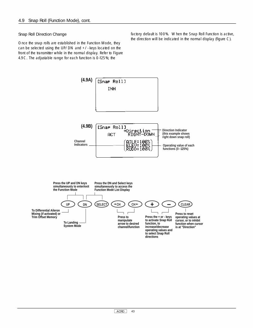
ACRO 43
4.9 Snap Roll (Function Mode), cont.
ChannelIndicators
Direction Indicator(this example showsright down snap roll)
Operating value of eachfunctions (0 –125%)
(4.9A)
(4.9B)
Snap Roll Direction Change
Once the snap rolls are established in the Function Mode, theycan be selected using the UP/DN and +/- keys located on thefront of the transmitter while in the normal display. Refer to Figure4.9C. The adjustable range for each function is 0-125%; the
factory default is 100%. When the Snap Roll Function is active,the direction will be indicated in the normal display (figure C).
Press the UP and DN keyssimultaneously to enter/exitthe Function Mode
Press the DN and Select keyssimultaneously to access theFunction Mode List Display
Press the + or - keysto activate Snap Rollfunction, toincrease/decreaseoperating values andto select Snap Rolldirections
Press tomanipulatearrow to desiredchannel/function
Press to resetoperating values atcursor, or to inhibitfunction when cursoris at "Direction"
DN SELECT CH CH CLEARUP
To Differential AileronMixing (if activated) orTrim Offset Memory
To LandingSystem Mode
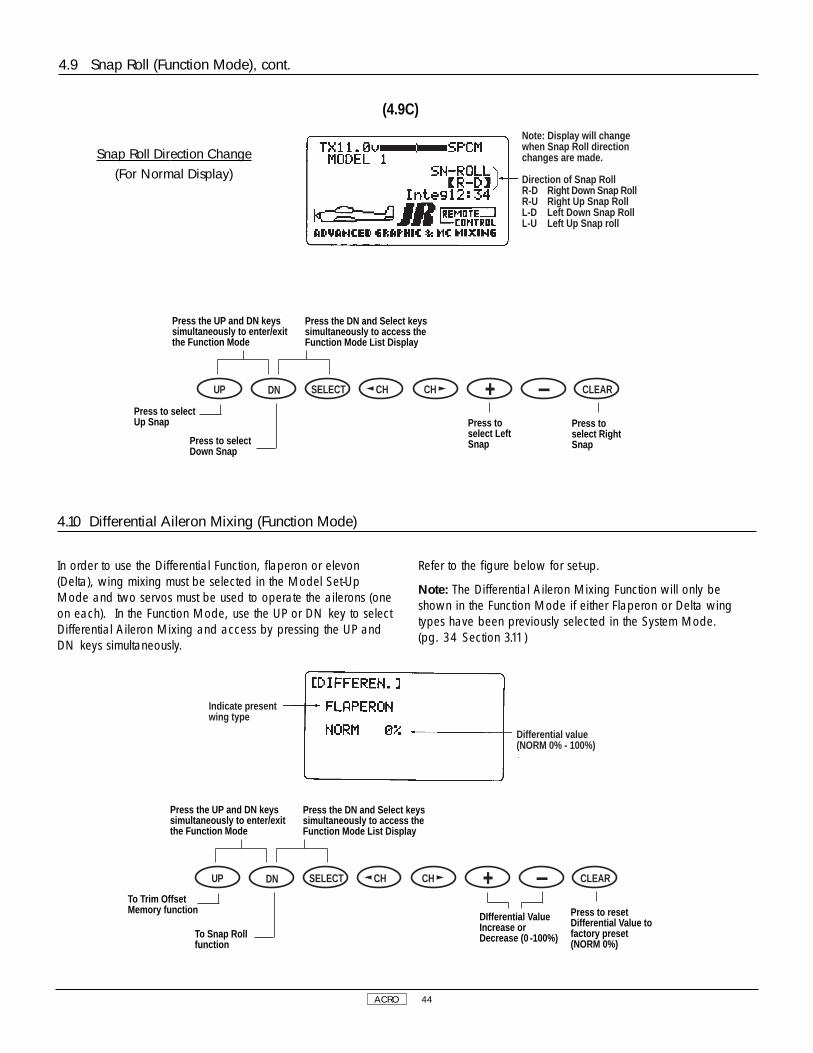
ACRO 44
In order to use the Differential Function, flaperon or elevon(Delta), wing mixing must be selected in the Model Set-UpMode and two servos must be used to operate the ailerons (oneon each). In the Function Mode, use the UP or DN key to selectDifferential Aileron Mixing and access by pressing the UP andDN keys simultaneously.
Refer to the figure below for set-up.
Note: The Differential Aileron Mixing Function will only beshown in the Function Mode if either Flaperon or Delta wingtypes have been previously selected in the System Mode.(pg. 34 Section 3.11)
4.10 Differential Aileron Mixing (Function Mode)
Indicate presentwing type
Differential value(NORM 0% - 100%)
Press the UP and DN keyssimultaneously to enter/exitthe Function Mode
Press the DN and Select keyssimultaneously to access theFunction Mode List Display
Press to resetDifferential Value tofactory preset(NORM 0%)
DN SELECT CH CH CLEARUP
To Trim OffsetMemory function
To Snap Rollfunction
DIfferential ValueIncrease orDecrease (0 -100%)
4.9 Snap Roll (Function Mode), cont.
(4.9C)
Note: Display will changewhen Snap Roll directionchanges are made.
Direction of Snap RollR-D Right Down Snap RollR-U Right Up Snap RollL-D Left Down Snap RollL-U Left Up Snap roll
Press the UP and DN keyssimultaneously to enter/exitthe Function Mode
Press the DN and Select keyssimultaneously to access theFunction Mode List Display
Press toselect LeftSnap
Press toselect RightSnap
DN SELECT CH CH CLEARUP
Press to selectUp Snap
Press to selectDown Snap
Snap Roll Direction Change(For Normal Display)
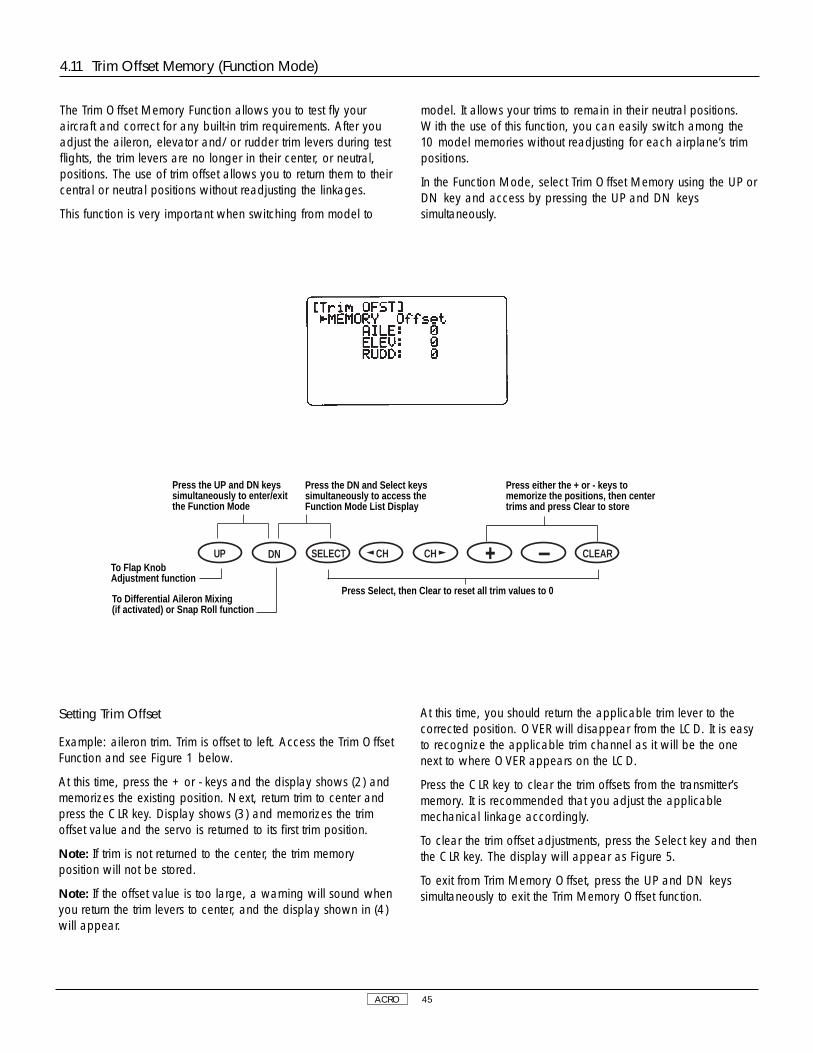
ACRO 45
The Trim Offset Memory Function allows you to test fly youraircraft and correct for any built-in trim requirements. After youadjust the aileron, elevator and/or rudder trim levers during testflights, the trim levers are no longer in their center, or neutral,positions. The use of trim offset allows you to return them to theircentral or neutral positions without readjusting the linkages.
This function is very important when switching from model to
model. It allows your trims to remain in their neutral positions.With the use of this function, you can easily switch among the10 model memories without readjusting for each airplane’s trimpositions.
In the Function Mode, select Trim Offset Memory using the UP orDN key and access by pressing the UP and DN keyssimultaneously.
4.11 Trim Offset Memory (Function Mode)
Press the UP and DN keyssimultaneously to enter/exitthe Function Mode
Press the DN and Select keyssimultaneously to access theFunction Mode List Display
Press either the + or - keys tomemorize the positions, then centertrims and press Clear to store
DN SELECT CH CH CLEARUPTo Flap KnobAdjustment function
To Differential Aileron Mixing (if activated) or Snap Roll function
Press Select, then Clear to reset all trim values to 0
Setting Trim Offset
Example: aileron trim. Trim is offset to left. Access the Trim OffsetFunction and see Figure 1 below.
At this time, press the + or - keys and the display shows (2) andmemorizes the existing position. Next, return trim to center andpress the CLR key. Display shows (3) and memorizes the trimoffset value and the servo is returned to its first trim position.
Note: If trim is not returned to the center, the trim memoryposition will not be stored.
Note: If the offset value is too large, a warning will sound whenyou return the trim levers to center, and the display shown in (4)will appear.
At this time, you should return the applicable trim lever to thecorrected position. OVER will disappear from the LCD. It is easyto recognize the applicable trim channel as it will be the onenext to where OVER appears on the LCD.
Press the CLR key to clear the trim offsets from the transmitter’smemory. It is recommended that you adjust the applicablemechanical linkage accordingly.
To clear the trim offset adjustments, press the Select key and thenthe CLR key. The display will appear as Figure 5.
To exit from Trim Memory Offset, press the UP and DN keyssimultaneously to exit the Trim Memory Offset function.

ACRO 46
Flap Knob Operating Adjustment
The Flap Knob Operating Value Adjustment Function allowsadjustment of the operational value of the flap channel (AUX 1)using the flap adjustment knob. The factory preset values are asfollows: Trim 30%; INH 0%; and Full 100%. These are merelystarting points. They can be changed to any value using the
+ or - keys. This function makes fine tuning of the flaps veryeasy.
In the Function Mode, use the UP or DN key to select Flap KnobAdjustment and access by pressing the UP and DN keyssimultaneously.
4.12 Flap Knob Adjustment (Function Mode)
flap POT Operatingvalue adjustmentFLAP TRIM: 30%POT. INH: 0%FLAPFULL: 100%
Press the UP and DN keyssimultaneously to enter/exitthe Function Mode
Press the DN and Select keyssimultaneously to access theFunction Mode List Display
Press to selectoperating value
↓30% Flap Trim
↓0% Pot. INH
↓100% Flap Full
DN SELECT CH CH CLEARUP
To ProgrammableMixing function
To Trim Offsetfunction
Operational ValueIncrease orDecrease (1% increments)
4.11 Trim Offset Memory (Function Mode), cont.
1
2
3
4
5

ACRO 47
Press the DN and Select keyssimultaneously to access theFunction Mode List Display
Accessing the Programable Mixing Functions
Place the transmitter power switch in the ON position. Press theMode UP and DN keys simultaneously to enter the Function
Mode. Press either the UP or DN keys until PROG. Mix 1appears in the upper left portion of the LCD (refer to figurebelow).
4.13 Programmable Mixing (1-6) (Function Mode)
Press the UP and DN keyssimultaneously to enter/exitthe Function Mode
Press the reset value atcursor to factory presetpostion/value or toinhibit Mixing function
DN SELECT CH CH CLEARUP
To ProgrammableMixing 2
To Flap POTAdjustment function
Press either the + or - key toactivate the mixing function; toincrease/decrease values; andto change the EXP functionfrom OFF to ON
Press to movethe cursor
Mixing Channel↓
Point↓
Switch
The XP8103 offers six (6) programmable mixes to be used for anumber of different purposes. The functions allows mixing anyone channel to any other channel.
The mix can remain ON at all times, or be switched OFF inflight using a number of different switches. (Refer to figure 4.13B).Each channel is identified by a four character name (i.e.,Aileron - AILE, Elevator - ELEV, etc.). The channel appearing firstis known as the “master channel,” or the channel to which youwant to mix. The second channel is known as the “slavechannel,” or the channel that is being mixed into the masterchannel. For example, AILE - RUDD would indicate aileron torudder mixing — each time the aileron stick is moved, theaileron will deflect, and the rudder will automatically move in thedirection and to the value input. Mixing is proportional, sosmall inputs of the master channel will produce small outputs ofthe slave channel. Each programmable mix has a mixing“offset.” The purpose of the mixing offset is to redefine theneutral position of the slave channel.
Multi-Point Programmable Mixing
Programmable mixes 1 and 2 have the capability for multi-pointprogrammable mixing. The graphic mixing curve, located on theright side of your screen, indicates the mixing curve selectedand is a useful reference tool when adjusting or storing points.Up to 5 points can be stored, and these points can be movedindependently to any desired servo position from 0 to 100%.(Refer to figure 4.13C).
SW Indicate Switch Lever Position When Mixing Is On
ON Mixing Always On
MIX Mixing Switch Toward Self
LAND Flap Switch In land Position
ELE>F Flap Switch In ELEV Position
GEAR Retracting Landing Gear SW Toward Self
(4.13B)

ACRO 48
Press the UP and DN keyssimultaneously to enter/exitthe Function Mode
Press the DN and Select keyssimultaneously to access theFunction Mode List Display
Press to reset value atcursor to factory presetposition/value, or toinhibit mixing
DN SELECT CH CH CLEARUP
To ProgrammableMixing (2-6)
To Flap KnobAdjustment function
Press to selectchannels to bemixed, and tomove cursor ongraph to points tobe adjusted
Press either the +or - key to activatethe mixingfunction, toincrease/decreasevalues, and tochange the EXPfunction from OFFto ON
Press to movethe cursor atleft of screen
4.13 Programmable Mixing (1-6) (Function Mode), cont.
(4.13C)
Assigning Channels
Using the SEL key, move the cursor to the left of the masterchannel. Press the left or right CH keys to position the cursorbelow the master or slave channel. Press the + or - keys to selectthe desired channels.
Operating with a Switch
Pressing the SEL key, position the cursor to the side of SW: andusing the + or - keys select the desired switch for the particularprogram mix being used. Refer to figure 4.13B.
Assigning Mixing Values
Position the cursor to the left of “Point” and press the left or rightCH keys to reverse the position point. Increase or decrease themixing value using the + or - keys or the CLR key. When youwish to reverse the mixing direction, press the - key to increasethe minus value to the desired position. To activate point 1 or 3with “INH” displayed, press the + or - key at that position todisplay mixing value. Press the CLR key if you want to inhibitmixing. Mixing value “0” can be set at points L, 2, and H bypressing the CLR key.
Mixing value (maximum ±100)
Master channel
Slave channel
Channel indicater
THRO: ThrottleAILE: AileronELEV: ElevatorRUDD: RudderGEAR: Retract GearFLAP: Flap (Aux1)SPOI: Spoiler (Aux2)AUX3: Extra Channel (AUX3)
point to be adjusted
Mixing switchMixing value atpresent stickposition
present stickposition
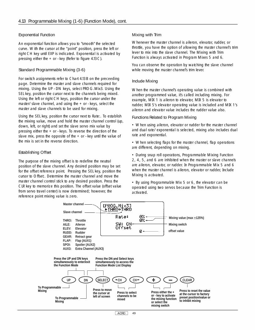
ACRO 49
4.13 Programmable Mixing (1-6) (Function Mode), cont.
Exponential Function
An exponential function allows you to "smooth" the selectedcurve. With the cursor at the “point” position, press the left orright CH key until EXP is indicated. Exponential is activated bypressing either the + or - key (Refer to figure 4.13C).
Standard Programmable Mixing (3-6)
For switch assignments refer to Chart 4.13B on the preceedingpage. Determine the master and slave channels required formixing. Using the UP - DN keys, select PROG.Mix3. Using theSEL key, position the cursor next to the channels being mixed.Using the left or right CH keys, position the cursor under themaster/slave channel, and using the + or - keys, select themaster and slave channels to be used for mixing.
Using the SEL key, position the cursor next to Rate:. To establishthe mixing value, move and hold the master channel control (up,down, left, or right) and set the slave servo mix value bypressing either the + or - keys. To reverse the direction of theslave mix, press the opposite of the + or - key until the value ofthe mix is set in the reverse direction.
Establishing Offset
The purpose of the mixing offset is to redefine the neutralposition of the slave channel. Any desired position may be setfor the offset reference point. Pressing the SEL key, position thecursor to Offset:. Determine the master channel and move themaster channel control stick to any desired position. Press theCLR key to memorize this position. The offset value (offset valuefrom servo travel center) is now determined; however, thereference point mixing value is zero.
Mixing with Trim
Whenever the master channel is aileron, elevator, rudder, orthrottle, you have the option of allowing the master channel’s trimlever to mix into the slave channel. The Mixing with TrimFunction is always activated in Program Mixes 5 and 6.
You can observe the operation by watching the slave channelwhile moving the master channel’s trim lever.
Include Mixing
When the master channel’s operating value is combined withanother programmed value, it’s called including mixing. Forexample, MIX 1 is aileron to elevator, MIX 5 is elevator torudder, MIX 5’s elevator operating value is included and MIX 1’saileron and elevator value includes the rudder value also.
Functions Related to Program Mixing
• When using aileron, elevator or rudder for the master channeland dual rate/exponential is selected, mixing also includes dualrate and exponential.
• When selecting flaps for the master channel, flap operationsare different, depending on mixing.
• During snap roll operations, Programmable Mixing Function2, 4, 5, and 6 are inhibited when the master or slave channelsare aileron, elevator, or rudder. In Programmable Mix 5 and 6when the master channel is aileron, elevator or rudder, IncludeMixing is activated.
• By using Programmable Mix 5 or 6, the elevator can beoperated using two servos because the Trim Function isactivated.
Master channel
Slave channel
THRO: ThrottleAILE: AileronELEV: ElevatorRUDD: RudderGEAR: Retract gearFLAP: Flap (AUX1)SPOI: Spoiler (AUX2)AUX3: Extra Channel (AUX3)
Mixing value (max ±125%)
Mixing switch
offset value
Press the UP and DN keyssimultaneously to enter/exitthe Function Mode
Press the DN and Select keyssimultaneously to access theFunction Mode List Display
Press to reset the valueat the cursor to factorypreset position/value orto inhibit mixing
DN SELECT CH CH CLEARUP
To ProgrammableMixing
To ProgrammableMixing
Press to selectchannels to bemixed
Press either the +or - key to activatethe mixing functionor select themixing switch
Press to movethe cursor atleft of screen

ACRO 50
4.14 Fail-Safe/Hold (Function Mode)
The Fail-Safe/Hold Function is available only when you use theXP8103 transmitter in either of the PCM modulations — S-PCMor Z-PCM. This function is designed to help minimize damage toyour airplane during a loss of signal to the receiver. The servoseither assume the fail-safe presets or hold the last good signalposition.
Note: In the PCM modulations, the Fail-Safe/Hold Functioncannot be totally disabled so that the servos will react tointerference in the same way as they do in a PPM system. This isonly possible with the use of a PPM receiver and the transmitterin the PPM modulation.
Note: Since the actual screen appearance varies, dependingon the modulation of your radio, refer to the appropriatemodulation section which follows (Z-PCM, S-PCM).
As noted earlier, if you are in the PPM modulation, the Fail-Safe/Hold Function is not applicable. Therefore, the Fail-Safe/Hold Function will not appear on your LCD in the PPMmode.
Refer to the Modulation Selection Section for more informationpertaining to the broadcast signal of your XP8103 airplanetransmitter.
Accessing the Fail-Safe/Hold Function in Z-PCMModulation
Hold (Z-PCM)
The Hold Function is automatically activated when the radio isturned ON and is in the Z-PCM modulation.
This function stops (or holds) the servos in the positions they werein just prior to the interference. Therefore, your airplanemaintains the position held immediately before the interferencewas experienced. When a clear signal is restored, the Hold
Function releases, and control of the airplane returns to you.
1. Place the transmitter power switch in the ON (upper)position.
2. While the power switch is in the ON position, press the UPand DN keys simultaneously to access the Function Mode.
3. Press either the UP or DN key until Fail-Safe appears in theleft portion of your LCD.
Note: If Fail-Safe does not appear on your LCD, it is becauseyou are transmitting in PPM. Fail-Safe is not applicable in thePPM mode. Refer to the Modulation Mode Selection Section formore information.
When the Fail-Safe Function is activated (i.e., when the signal isinterrupted), the transmitter automatically moves each servo to apreset position. The position that each servo assumes isdetermined by you, as is the time length of interference that mustoccur before servo movement.
After the interference has ceased, control of the airplane returnsimmediately to you.
There are three time delays to choose from: 1/4 (0.25) second,1/2 (0.50) second and 1.0 second. These time delays are theamount of time it takes, starting the moment the interferenceoccurs, until the servos assume their preset positions.
Setting Fail-Safe/Hold Memory in Z-PCM Modulation
1. After accessing the Fail-Safe Function, it is time to adjust theFail-Safe presets.
2. Select among the three time delays (1/4, 1/2 or 1.0seconds). To do so, simply press the + or - key until theappropriate delay appears on the screen.
Move sticks to thedesired Fail-Safepostion, then press theClear key once to storesettings
DN SELECT CH CH CLEARUP
Press either the +or - key to selecttime delay
↓Hold
↓0.25 Sec
↓0.5 Sec
↓1.0 Sec
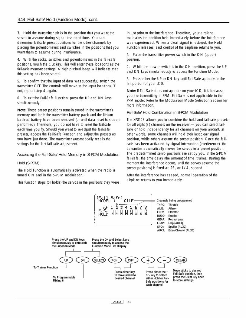
ACRO 51
3. Hold the transmitter sticks in the position that you want theservos to assume during signal loss conditions. You candetermine fail-safe preset positions for the other channels byplacing the potentiometers and switches in the positions that youwant them to assume during interference.
4. With the sticks, switches and potentiometers in the fail-safepositions, touch the CLR key. This will enter these locations as thefail-safe memory settings. A high pitched beep will indicate thatthis setting has been stored.
5. To confirm that the input of data was successful, switch thetransmitter OFF. The controls will move to the input locations. Ifnot, repeat step 4 again.
6. To exit the Fail-Safe Function, press the UP and DN keyssimultaneously.
Note: These preset positions remain stored in the transmitter’smemory until both the transmitter battery pack and the lithiumback-up battery have been removed (or until data reset has beenperformed). Therefore, you do not have to reset the fail-safeeach time you fly. Should you want to re-adjust the fail-safepresets, access the Fail-Safe Function and adjust the presets asyou have just done. The transmitter automatically recalls thesettings for the last fail-safe adjustment.
Accessing the Fail-Safe/Hold Memory in S-PCM Modulation
Hold (S-PCM)
The Hold Function is automatically activated when the radio isturned ON and in the S-PCM modulation.
This function stops (or holds) the servos in the positions they were
in just prior to the interference. Therefore, your airplanemaintains the position held immediately before the interferencewas experienced. When a clear signal is restored, the HoldFunction releases, and control of the airplane returns to you.
1. Place the transmitter power switch in the ON (upper)position.
2. While the power switch is in the ON position, press the UPand DN keys simultaneously to access the Function Mode.
3. Press either the UP or DN key until Fail-Safe appears in theleft portion of your LCD.
Note: If Fail-Safe does not appear on your LCD, it is becauseyou are transmitting in PPM. Fail-Safe is not applicable in thePPM mode. Refer to the Modulation Mode Selection Section formore information.
Fail Safe/Hold Combination in S-PCM Modulation
The XP8103 allows you to combine the hold and fail-safe presetsfor all eight (8) channels on the receiver — you can select fail-safe or hold independently for all channels on your aircraft. Inother words, some channels will hold their last clear signalposition, while others assume the preset position. Once the fail-safe has been activated by signal interruption (interference), thetransmitter automatically moves the servos to a preset position.The predetermined servo positions are set by you. In the S-PCMfail-safe, the time delay (the amount of time it takes, starting themoment the interference occurs, until the servos assume thepreset positions) is fixed at .25, or 1/4, second.
After the interference has ceased, normal operation of theairplane returns to you immediately.
4.14 Fail-Safe/Hold (Function Mode), cont.
THRO: ThrottleAILE: AileronELEV: ElevatorRUDD: RudderGEAR: Retract gearFLAP: Flap (AUX1)SPOI: Spoiler (AUX2)AUX3: Extra Channel (AUX3)
Channels being programmed
Press the UP and DN keyssimultaneously to enter/exitthe Function Mode
Press the DN and Select keyssimultaneously to access theFunction Mode List Display
Move sticks to desiredFail-Safe position, thenpress the Clear key onceto store settings
DN SELECT CH CH CLEARUP
To Trainer Function
To ProgrammableMixing 6
Press either keyto move arrow todesired channel
Press either the +or - key to selecteither Hold or Fail-Safe positions foreach channel

ACRO 52
Setting the Fail-Safe/Hold Memory in S-PCM Modulation
1. After accessing the Fail-Safe Function, it is time to adjust thefail-safe presets.
2. Select all of the channels for which you want to enter a fail-safe preset. This is done by pressing the left or right CH keyand moving the cursor arrow over the desired channel. Pressingthe + or - key will cause the particular channel to assume a
“hold” or “preset” fail-safe condition which is determined bypositioning the particular control and pressing the CLR key. Thetransmitter will memorize the switch fail-safe position andautomatically transfer the setting to the receiver.
3. Confirmation of proper fail-safe presets/holds is made byturning the transmitter OFF and observing the aircraft’s controlfunctions.
4.14 Fail-Safe/Hold (Function Mode), cont.
The XP8103 transmitter employs two separate types of trainersystems:
A. Normal trainer system — all functions are controlled byeither the master transmitter or the slave transmitter.
B. Programmable function trainer — stick functions may beassigned to the slave one at a time. Since the control functionscan be transferred one at a time, students can concentrate ononly one function at a time until they are competent to fly solo.
Basic Connections and Limitations
1. The slave transmitter must be PPM (Pulse Position Modulation)with a DSC (direct servo control) jack. If the slave transmitter isPPM/PCM selectable, select PPM. The master transmitter can beS-PCM, Z-PCM or PPM.
2. Plug the trainer cord into each transmitter’s DSC jack. Noteeach transmitter will appear to be ON, but neither is actuallytransmitting at this time.
3. Switch the master transmitter ON. Do not switch on theslave transmitter; you must only have the master transmitterON.
4. Pull the trainer switch on the master transmitter toward you totransfer control to the slave. Releasing the switch automaticallyreverts control to the master transmitter.
5. Be sure the slave transmitter servo reversing, dual rates, andpoint adjustment and trims are identical to the master transmitter.This can be checked by pulling the trainer switch toward you. Ifthe control surfaces move, adjust the slave transmitter until thetrainer switch can be activated without a change of the controlsurface position.
A. Using the Normal Trainer System
In this mode, all functions are switched from the master to theslave using the trainer switch. This is the normal mode. Nofunction set-up (reversing switch or travel adjust) is necessary toactivate this system.
4.15 Trainer (Function Mode)
When switch is inupper position,Fail-Safe isactivated
When switch is inlower position, Hold(last command) isactivated
Value represents thestored position offail-safe mode of thechannel indicated bythe cursor

ACRO 53
B. Use of Programmable Trainer Function
In this mode, the master may assign functions to the student oneat a time to make learning to fly easier. For example, the master
may assign the slave rudder and elevator. Then, when the trainerswitch is activated (pulled toward you), the slave has control ofonly rudder and elevator while the master retains control ofthrottle and aileron.
The normal display screen will show thetype of trainer function selected once thetrainer function is activated
programmable trainer displayChannel display being programmed
If an arrow appears onthe Master transmitterin this position, itindicates the directionthe Slave channel trimlever must be movedon the Slavetransmitter
SLAV: Applicable channel set to SlaveMAST: Applicable channel to Master
Normal trainer display
4.15 Trainer (Function Mode), cont.
Press the UP and DN keyssimultaneously to enter/exitthe Function Mode
Press the DN and Select keyssimultaneously to access theFunction Mode List Display
Press to reset tofactory presetposition (All Master)
DN SELECT CH CH CLEARUP
To Timer Function
To Fail-Safe (PCMOnly) or programmablemixing
Press either keyto move arrow todesired channel
Press either the + or -key to select channelsto be activated(Master-Slave) When all channels areset for Master,condition is set toNormal Trainer
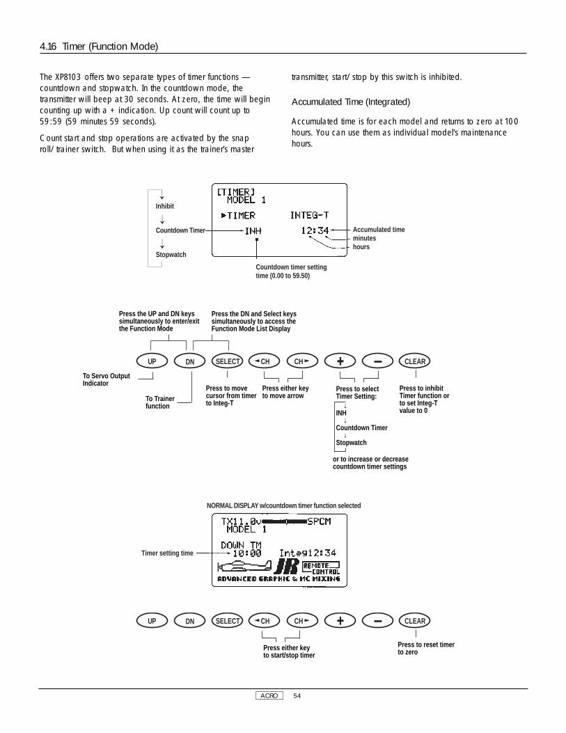
ACRO 54
The XP8103 offers two separate types of timer functions —countdown and stopwatch. In the countdown mode, thetransmitter will beep at 30 seconds. At zero, the time will begincounting up with a + indication. Up count will count up to59:59 (59 minutes 59 seconds).
Count start and stop operations are activated by the snaproll/trainer switch. But when using it as the trainer’s master
transmitter, start/stop by this switch is inhibited.
Accumulated Time (Integrated)
Accumulated time is for each model and returns to zero at 100hours. You can use them as individual model’s maintenancehours.
4.16 Timer (Function Mode)
Accumulated timeminuteshours
Countdown timer settingtime (0.00 to 59.50)
Inhibit
Countdown Timer
Stopwatch
Timer setting time
NORMAL DISPLAY w/countdown timer function selected
Press to reset timerto zero
DN SELECT CH CH CLEARUP
Press either keyto start/stop timer
Press the UP and DN keyssimultaneously to enter/exitthe Function Mode
Press the DN and Select keyssimultaneously to access theFunction Mode List Display
Press to selectTimer Setting:
↓INH
↓Countdown Timer
↓Stopwatch
DN SELECT CH CH CLEARUP
To Servo OutputIndicator
To Trainerfunction
Press either keyto move arrow
Press to inhibitTimer function orto set Integ-Tvalue to 0
or to increase or decreasecountdown timer settings
Press to movecursor from timerto Integ-T

ACRO 55
This function displays each servo’s operating value. Each barcenter indicates neutral position. Left or right dots indicate 50%,100% and 150%.
Note: All indications are actual positions including adjustmentsand mixing. It is also possible to view servo travel/servodirections when mixing functions are activated.
4.17 Servo Output Indicator (Function Mode)
50%100%150%
ATV Travel
Press the UP and DN keyssimultaneously to enter/exitthe Function Mode
Press the DN and Select keyssimultaneously to access theFunction Mode List Display
DN SELECT CH CH CLEARUPTo Dual RateExponential function
To Timerfunction

ACRO 56
XP8103 DATA SHEET ACRO
DIFFERENTIAL
FAIL-SAFE (SPCM • ZPCM)
SPCM • ZPCM • PPM

HELI 57
IV. Helicopter Section

HELI 58
1. Transmitter Controls
1.1 Control Identification and Location
Throttle (collective)/Rudder Stick
Input Keys
Aileron Trim
Elevator Trim
Elevator/Aileron Stick
Antenna
Hovering Throttle Knob (Aux2)
Carrying Handle
LCD Display (Do Not Press)
Gear/Inverted Switch
Aileron Dual Rate Switch
Rudder Dual Rate Switch
Throttle Hold Switch
Power Switch
Rudder Trim
Throttle Trim
Neck Strap Eyelet
Timer/Trainer Switch
Hovering Pitch Knob
Elevator Dual Rate Switch
Flight Modes (Aux 3)
Pitch Trim Knob
Channel Assignment/Throttle ALT
Channel # TX Function Airplane Function1 Thro Throttle Channel2 Aile Aileron Channel3 Elev Elevator Channel4 Rudd Rudder Channel5 Gear Gear Channel6 Aux 1 Auxillary 1 Channel (Pitch)7 Aux 2 Auxillary 2 Channel (Gyro Sensitivity)8 Aux 3 Auxillary 3 Channel
Throttle ALT
The Throttle ALT function makes the throttle stick trim active onlywhen the throttle stick is at less than half throttle. This gives easy,accurate idle adjustments without affecting the high throttleposition.

HELI 59
Helicopter Version Transmitter–Airplane Mode
Aux 3
Timer/Snap Roll/Trainer Switch
Landing Mode Switch
Elevator Dual Rate Switch
AUX 2 Knob
Throttle Trim
Throttle/Rudder Stick
Neck Strap Eyelet
Rudder Trim
Power Switch
Input Keys
Aileron Trim
Elevator/Aileron Stick
Elevator Trim
Gear/Mixing Switch
Aileron Dual Rate Switch
Mixing Switch
Flap Trim Knob
Carrying Handle
LCD Display – DO NOT PRESS
Antenna
Rudder Dual Rate/AUX 2 Switch
Flaperon/Flap Trim Knob (Pot. 7)
Trainer/Timer Switch
Landing Mode Switch
Elevator Dual Rate Switch
Dual Flaps/Aileron Trim Knob (Pot.5)
Spoiler Trim
Spoiler/Rudder Stick
Neck Strap Eyelet
Rudder Trim
Power Switch
Input Keys
Aileron Trim
Elevator/Aileron Stick
Elevator Trim
Crow/Camber
Aileron Dual Rate Switch
Mixing Switch
Flap Trim Knob (Pot. 6)
Carrying Handle
LCD Display – DO NOT PRESS
Antenna
Rudder Dual Rate Switch
Channel Assignment1. THRO Throttle Channel 2. AILE Aileron Channel 3. ELEV Elevator Channel 4. RUDD Rudder Channel 5. GEAR Gear Channel 6. AUX 1 Auxiliary 1 Channel Flap) 7. AUX 2 Auxiliary 2 Channel (Spoiler)8. AUX 3 Auxiliary 3 Channel
Channel Assignment1. SPOI Spoiler Channel 2. AIL1 Left Aileron Channel 3. ELEV Elevator Channel 4. RUDD Rudder Channel 5. AIL2 Right Aileron Channel 6. FLAP Left Flap Channel for Dual Flaps7. AUX 2 Right Flap Channel for Dual Flaps8. AUX 3 Auxiliary 3 Channel
Helicopter Version Transmitter–Glider Mode

1.3 Connections
HELI 60
1.2 Switch Warning Safety Feature (Helicopter Mode)
When the XP8103 transmitter is operated in the helicopter mode,there is a warning system that is employed to avoid accidentaloperation when the power switch is initially turned ON.
If all or one of the flight mode switch, inverted switch or throttlehold switch are not in the normal setting, you will hear an alarmsound and see a message displayed on the LCD. When alllever switches are returned to the normal condition, the display
will return to normal. Note: If the inverted and throttle holdswitch functions are not activated prior the power switch beingturned ON, no alarm will sound.
Below is the display example of WARNING CONDITIONwhen the power switch is ON:
throttle hold switch flight mode switch
inverted switch
Receiver Battery4N-10004N1000
4.8V 1000mAhJAPAN REMOTE CONTROL CO., LTD.
®
ON
OF
F
Auxillary 3Auxiliary 2/Gyro RateAuxiliary 1/PitchGearRudder
Elevator
Aileron
Throttle
Deluxe Switch HarnessJRPA001
Chargecord orD.S.C. Receptacle
JRPA024
Chargecord or D.S.C.D.S.C. – JRPA132Chgr. – JRPC221
Pulse Code Modulation
BATTAUX 4AUX 3AUX 2AUX 1GEARRUDDELEVAILETHRO
9 CHANNEL RECEIVER
NER-649S
NEW ABC & W SYSTEM
JAPAN REMOTE CONTROL CO. LTDMADE IN JAPAN
72 MHZ
Not Used
NER-649SS-PCM Receiver
JRPR649(PCM only)
NER-549FM Receiver
JRPR549(FM only)

Connect the gyro to the axis to be controlled (commonly rudderchannel) per the illustration below.
The gyro unit should be mounted as close as possible to thecenter of gravity of the helicopter (near the main shaft) at a
position where vibration is minimal. Please refer to the specificgyro/helicopter instructions for proper gyro placement andinstallation.
HELI 61
1.4 Gyro Connections
Receiver(PCM) NER-649S(FM) NER-549
Sensitivity Adjusting Trimmer(NEJ 120, NEJ160 only)
Gyro Amplifier
Gyro
JumperConnector(NEJ-120,NEJ-160 only)
Gain C
Plug servolead intoRudd - SV
Gyro unit
Gain control
Rudder servo
Rx Ruddinsert into rudd channelof receiver
insert into Aux 2 channelof receiver

transmitter voltagemodel number
modulation typemodel name (whennames are entered)
integrated timer
HELI 62
• You will hear a clicking (beeping) sound to confirm input hasbeen achieved.
• Except for the CLEAR key, the AUTO advance system, (twospeed scrolling) is active when you continue pressing down ona key.
• The SEL keys or CH keys are used to scroll through, ormanipulate functions within a specific program or display.
2.1 Input Key Function
Function Selection keys(press both keyssimultaneously to enter orexit the function mode)
Normal Display Screen
Press both keys simultaneouslyto access the system mode orfunction mode lists.
used for changing pages orindicated displays
used for channel changes in themodel set-up and function modes
Data Entry Keys
Up Key
Down Key Select Key Channel Key Increase Key Decrease Key
Clear Key
2.2 Normal Display
2. General Information
SELECT L /+ R/- CLEAR

HELI 63
2.2 Normal Display, cont.
DN SELECT CH CH CLEARUP
Press simultaneouslyto access the ListMode/System Set-Up Mode
Press Select andeither the + or - keyssimultaneously toadjust the contrast ofthe LCD display
Press the Clear keyto reset to factorysettingsPress the UP and DN keys
simultaneously to changeto Function Mode (withpower switch ON)
When timer function isactive, use CH key tostart/stop timer
Press the UP and DN keyssimultaneously and switch thepower from OFF to ON tochange the system to theSystem Set-Up Mode
From the Normal Display, the following inputs can be made:
When setting various functions with the buttons shown below,start either in the Function Mode or the System Set-Up Mode.
The Aux 3 channel (channel #8) is accessible either through anindependent switching of the flight mode 3 position switch, orthrough mixing using Aux 3 (channel #8) as a slave channel(Refer to section 4.14 page 87 of this manual for ProgrammableMixing Function).
When used in conjunction with the flight mode switch, Aux 3(channel #8) is of the non-proportional variety having only a
low-mid-high servo travel, with low and high values adjustablethrough the servo travel adjustment function (section 4.5 page76).
When used as a mixed slave channel, Aux 3 (channel #8)becomes fully proportional and separate from the flight modeswitch. Travel adjustment is then available either through thetravel adjust function, or the programmable mixing function.
2.3 Aux 3 Function (Channel #8)

HELI 64
3.1 System Set-Up Mode
[INFO-DISP]
To set the System Set-Up Mode, press the UP and DN keyssimultaneously and turn the power switch from OFF to ON.Functions are selectable by pressing either the DN or UP keys.Individual settings are explained later at each function. In thismode, servos are not activated, but operating signals are
transmitting (only when the Tx module is in place). However, useextra caution not to interfere with other frequencies. By pressingthe DN and UP keys simultaneously, you can return to the normaldisplay, which allows the servos to again operate.
Use either the UPor DN key to scrollthrough the menuand access theapplicable function
System Set-Up Mode
Pg. 66 Information Display
Pg. 66 Model Selection and Copy Function
Pg. 67 Model Name Input
Pg. 68 Model Type Selection
Pg. 68 Data Reset
Pg. 69 Modulation Selection
Pg. 70 Data Transfer
Pg. 72 Input Selection –Aux 2, channels can be used for gyrosensitivity adjustment
3. System Set-Up Mode Functions
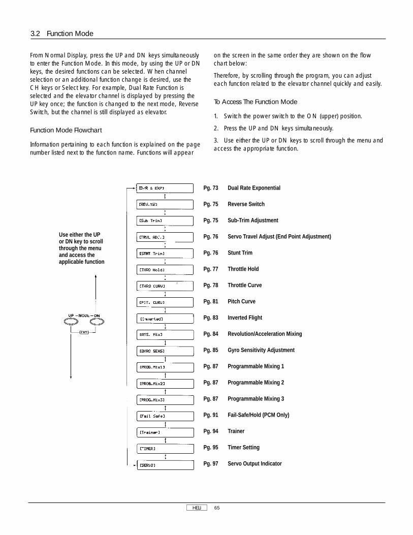
HELI 65
From Normal Display, press the UP and DN keys simultaneouslyto enter the Function Mode. In this mode, by using the UP or DNkeys, the desired functions can be selected. When channelselection or an additional function change is desired, use theCH keys or Select key. For example, Dual Rate Function isselected and the elevator channel is displayed by pressing theUP key once; the function is changed to the next mode, ReverseSwitch, but the channel is still displayed as elevator.
Function Mode Flowchart
Information pertaining to each function is explained on the pagenumber listed next to the function name. Functions will appear
on the screen in the same order they are shown on the flowchart below:
Therefore, by scrolling through the program, you can adjusteach function related to the elevator channel quickly and easily.
To Access The Function Mode
1. Switch the power switch to the ON (upper) position.
2. Press the UP and DN keys simultaneously.
3. Use either the UP or DN keys to scroll through the menu andaccess the appropriate function.
3.2 Function Mode
Use either the UPor DN key to scrollthrough the menuand access theapplicable function
Pg. 73 Dual Rate Exponential
Pg. 75 Reverse Switch
Pg. 75 Sub-Trim Adjustment
Pg. 76 Servo Travel Adjust (End Point Adjustment)
Pg. 76 Stunt Trim
Pg. 77 Throttle Hold
Pg. 78 Throttle Curve
Pg. 81 Pitch Curve
Pg. 83 Inverted Flight
Pg. 84 Revolution/Acceleration Mixing
Pg. 85 Gyro Sensitivity Adjustment
Pg. 87 Programmable Mixing 1
Pg. 87 Programmable Mixing 2
Pg. 87 Programmable Mixing 3
Pg. 91 Fail-Safe/Hold (PCM Only)
Pg. 94 Trainer
Pg. 95 Timer Setting
Pg. 97 Servo Output Indicator
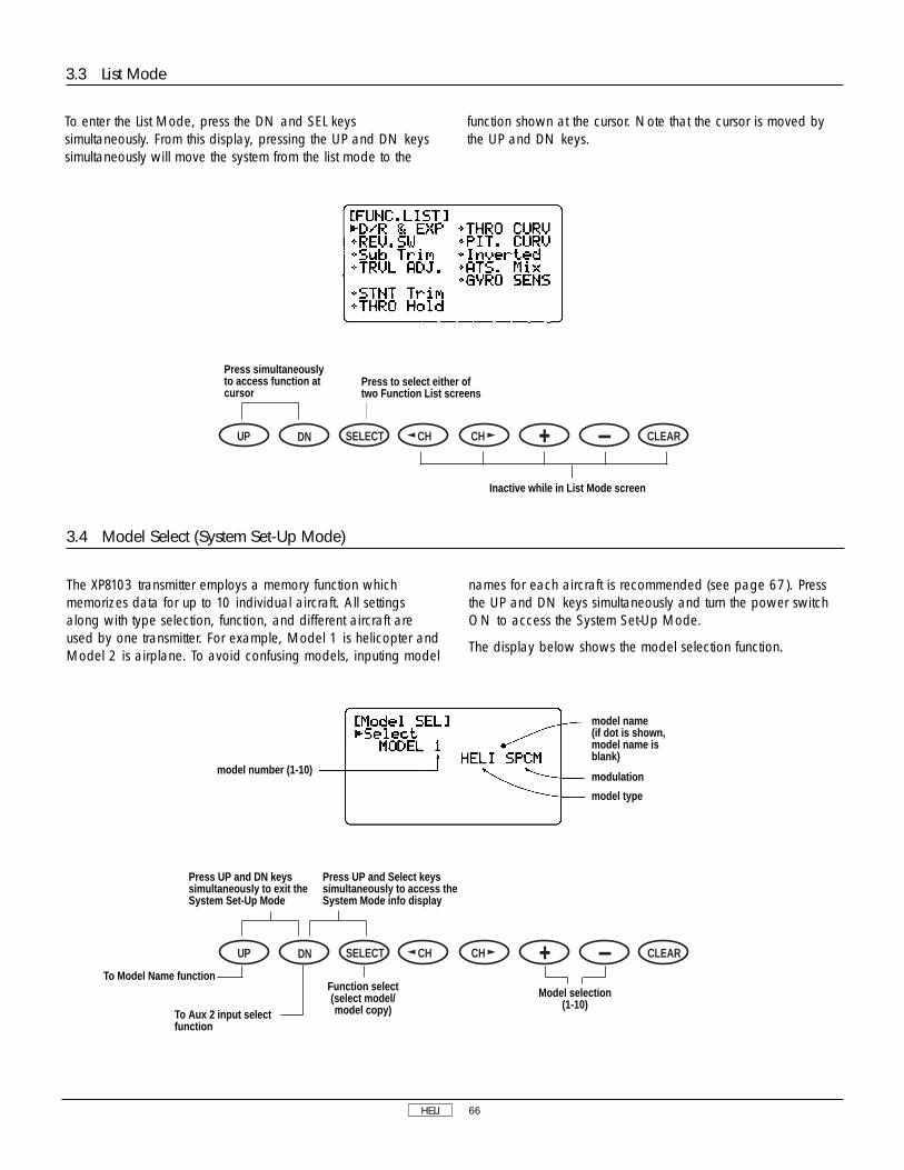
HELI 66
3.4 Model Select (System Set-Up Mode)
The XP8103 transmitter employs a memory function whichmemorizes data for up to 10 individual aircraft. All settingsalong with type selection, function, and different aircraft areused by one transmitter. For example, Model 1 is helicopter andModel 2 is airplane. To avoid confusing models, inputing model
names for each aircraft is recommended (see page 67). Pressthe UP and DN keys simultaneously and turn the power switchON to access the System Set-Up Mode.
The display below shows the model selection function.
To enter the List Mode, press the DN and SEL keyssimultaneously. From this display, pressing the UP and DN keyssimultaneously will move the system from the list mode to the
function shown at the cursor. Note that the cursor is moved bythe UP and DN keys.
3.3 List Mode
DN SELECT CH CH CLEARUP
Press simultaneouslyto access function atcursor
Press to select either oftwo Function List screens
Inactive while in List Mode screen
DN SELECT CH CH CLEARUP
Press UP and DN keyssimultaneously to exit theSystem Set-Up Mode
model number (1-10)
model name(if dot is shown,model name isblank)
modulation
model type
To Model Name function
To Aux 2 input selectfunction
Function select (select model/model copy)
Model selection(1-10)
Press UP and Select keyssimultaneously to access theSystem Mode info display

HELI 67
3.5 Copy Select Function (System Set-Up Mode)
The Copy Select Function enables you to copy all of the settingsof your current model to another memory (model number) within
the same transmitter. This is very useful when setting up oneaircraft several different ways.
model names(if dot is shown, modelname is blank)
existing modelnumber
model number to betransferred to.
3.6 Model Names (System Set-Up Mode)
DN SELECT CH CH CLEARUP
Press UP and DN keyssimultaneously to exit theSystem Set-Up Mode
model typemodel number
modulation letter position beinginputed (8 characters)
Press the Select key toaccess the copy functionin Model Select mode
To Model Name function
To Aux 2 inputselect function
Function select (select model/copy) Model selection —
use to select modelto be copied to
Activate copyfunction
DN SELECT CH CH CLEARUP
Press UP and DN keyssimultaneously to exit theSystem Set-Up Mode
Press the DN and Select keyssimultaneously to access thesystem mode info display
To Model Type Selectionfunction
To Model Select/Copyfunction
Press to changeinput letter at arrow
Press to changeinput letter arrowposition
Changes input letterto blank space onlywhere arrow islocated
This function is used to input model names individually. Eachmodel’s name is displayed in the normal screen automatically.when that model is selected. To avoid confusing models,inputing model names is recommended. You can input a
maximum of 8 characters for each model name.
In the System Set-Up Mode, select the Model Name Functionusing the UP or DN key. Once selected, simultaneously press theUP and DN keys to access.

HELI 68
3.8 Data Reset (System Set-Up Mode)
The Data Reset Function allows you to reset all the functions andsettings for the current model to the factory pre-set conditions.Resetting does not affect the data already programmed for othermodels. Be sure to confirm that you need to reset the data of thecurrently indicated model in order to prevent accidental loss ofvaluable data.
Note: If a model name has been input and is reset, the modelname will not be removed, only the data. Please refer to theModel Name Function for information on how to change themodel's name.
To access Data Reset, select Model Reset in System Set-Up andpress the UP and DN keys simultanelously.
3.7 Model Type Selection (System Set-Up Mode)
The XP8103 is capable of performing as a helicopter, airplaneor glider radio with full functions for each.
It can also memorize data for 10 models individually.
Note: If the power switch is turned OFF immediately afterselecting the new model type, the change will not be saved.To change and save the model type press the UP or DN keys, orpress UP and DN keys or DN and SEL keys simultaneously. Atthis time, existing model data is replaced by the model type
aircraft data selected. Be sure to confirm the model name toprevent accidental loss of your important data. To cancel thisfunction, return to former model type or turn the power switchOFF.
Note: When you select helicopter or glider model type on thistransmitter, allocation of lever switches, etc., will also change.Please refer to the helicopter or glider section of this instructionmanual for their functions.
DN SELECT CH CH CLEARUP
Press simultaneously tochange and save modeltype
Press the DN and Select keyssimultaneously to access thesystem mode info display
To Data Resetfunction
To Model Name function
Press to movearrow and selectmodel type
DN SELECT CH CH CLEARUP
Press simultaneously toexit the System Set-UpMode
To Modulation Selectfunction
To Model Type Selectfunction
model number tobe reset
Press to return tofactory preset data
Model numberModel name (if blank,no model name hasbeen stored)Helicopter
Airplane
Glider
Arrow indicatesexisting modeltype

HELI 69
3.9 Modulation Select (System Set-Up Mode)
TThe Modulation Selection Function enables your XP8103 totransmit to a variety of JR receivers that are already, or may soonbe, in existence. You can select from either S-PCM or Z-PCMmode, depending on the Central Processing Unit within yourreceiver, or from PPM (Pulse Position Modulation—FM). Refer tothe receiver compatibility chart for the correct modulation.
Caution: After making modulation changes, you must presseither the UP and DN, or the DN and SEL keys simultaneously toaccept the new modulation type. If the Tx power switch is turnedOFF before this procedure, the modulation change will not besaved.
Tx Modulation Compatible # of Channels Receivers & Brief Description
PPM (FM) NER-226 6 (micro)PPM (FM) NER-228 8PPM (FM) NER-327x 7PPM (FM) NER-527x 7 (micro)PPM (FM) NER-529x 9 (micro)PPM (FM) NER-549 9PPM (FM) NER-600 6 (micro)
Tx Modulation Compatible # of Channels Receivers & Brief Description
Z-PCM NER-236 6 (micro)Z-PCM NER-627XZ or
627 “G” series 7Z-PCM NER- J329P 9Z-PCM NER-910XZ 10S-PCM NER-D940S 10S-PCM NER-649S 9
Receiver Compatibility Chart
Modulationselection SPCM,ZPCM, or PPM(FM)
DN SELECT CH CH CLEARUP
Press the UP and DN keys or DN andSelect keys simultaneously toaccept the new modutation type,and exit the System Set-Up Mode
Press the DN and Select keys toaccept the new modulation andaccess the system info display
To Data Transferfunction
Model NumberModel Type
Modulation
To Data Resetfunction
Reset modulationto SPCM
In system Set-Up Mode, select Modulation Select using the UPand DN keys and press the UP and DN keys simultaneously toaccess.

HELI 70
CLR start transmitting
transmitting counter(0-100%)
make sure that the receivingmode transmitter (Tx to beprogrammed) is in the stand-bycondition.
Transfer Procedure
1. Select the model number to be transferred (transmitting modeside) through the model select function. (See page 66 forinformation on Model Select Function.)
2. Both transmitters: With the power switches OFF, press the UPand DN keys simultaneously while inserting the trainer cord intothe DSC jacks of both transmitters.
3. Both transmitters: Select the Transfer Fuction by pressing theUP or DN key. Then simultaneously press the UP and DN keys toenter the Transfer Function.
4. Receiving mode transmitter (Tx to be programmed): Press theSelect key until the screen reads "Receive." Select the receivingmodel number by pressing the + or - keys. Next, press the CLRkey to activate the receiving stand-by mode.
5. Transmitting mode transmitter (Tx with program to betransferred): Press the CLR key to start transmitting data. Bothtransmitters will indicate [End ok!] display when the transmittingis complete.
3.10 Data Transfer
This function is used to transfer all existing memorized data for amodel from one XP8103 transmitter to another XP8103 transmitter.
Use the + and - keys to select models to be transferred andactivate by pressing the CLR key.
To avoid the loss of important data, re-confirm model nameswhen transferring.
Caution: Please use special caution when copy function isactivated as existing data is replaced with new data.
Caution: When the battery alarm is activated (battery low), thecopy function is not operational.
Transmitting mode
Model number
Display indicates DSC cord isnot connected, or Tx powerswitch is on/off
Press + or -keys to selectmodels to betransferred
DN SELECT CH CH CLEARUP
Press the UP and DN keyssimultaneously to enter/exit theSystem Set-Up Mode
Press the DN and Select keyssimultaneously to access theSystem Mode info display
To Aux 2 inputselect function
To Modulationselect function
SelectTransmitting/Receiving Mode
Press + or -keys to selectthe receivingmodel number
Press to starttransmittingdata
DN SELECT CH CH CLEARUP
To Aux 2 inputselect function
To Modulationselect function
Transmitting/Receiving Modeselect

HELI 71
existing model number
CLR key to startstand-by receiving
+ or - to select models
model number tobe copy Receiving counter (0-100%)
When there is a data receiving failure during transmitting, thecounter will stop. At this time, press the CLR key to stop thereceiving condition. Check to be sure the receiving counter isoperating normally and ended with 100%. If there is any failure
of transferring, the display will appear as follows:
3.10 Data Transfer, cont.
stand-bycondition
receivingcounter0-100%
stand-by receiving condition
When the receiving counter is stopped or you see ERRORindicated, check the DSC cord connections or trainer cordconditions and try again. When data has been receivedcorrectly, you will see [End ok] display. Be sure that thereceiving mode transmitter is in stand-by condition first. Then onthe transmitting transmitter press the CLR key to start transmitting.
Also ensure that when transferring is complete, previous datastored in the receiving side transmitter is covered by new datatransferred.
Note: This function does not work when the battery alarm isflashing.
Receivingmodel select
Press to standbyreceiving/stopreceiving condition
DN SELECT CH CH CLEARUP
To Aux 2 inputselection function
To Modulationselect function
Transmitting/Receiving Modechange
Press to starttransmitting
DN SELECT CH CH CLEARUP
To Aux 2 inputselect
To Modulationselect
Transmitting/Receiving Modeselect

HELI 72
Aux 2 (Channel #7) Input Selection
The Aux 2 Channel Input Selection Function allows you to selectwhich switch, pitch trim knob, or throttle hold switch will activatethe Aux 2 Function. If you are using the Aux 2 Function (channel#7) for remote gyro sensitivity, JR TEC-1000 carburetoroperation, etc., this function should remain in the factory INHposition.
When using the Aux 2 Function for the gyro sensitivity, you can
change the rudder dual rate and the gyro sensitivity at the sametime. Conversely, if the throttle hold switch is selected, the gyrosensitivity is changed only when the throttle hold is activated.
Press the UP and DN keys simultaneously and turn the powerswitch ON to access the system Set-Up Mode. Using the UPand DN keys, select Input Select Function and press the UP andDN keys simultaneously to access.
3.11 Input Selection Function (System Set-Up Mode)
Aux 2 channel switchassignment
Choices:INH: InhibitHold SW: Hold SwitchPit. Trim: Pitch Trim
Knob
Gear Channel Switch InputACT: ActiveINH: Inhibit
To Model Selectfunction
To Data Transferfucntion
Press either the+ or - key toselect the switchassignment or toactivate/inhibitthe Gear Switchfunction
Press to change Aux 2from INH to Hold Switch,or to change gear fromINH to active
DN SELECT CH CH CLEARUP
Press either keyto move the arrowfrom Aux 2 toGear
Press the UP and DN keyssimultaneously to enter/exit theSystem Set-Up Mode
Press the DN and Select keyssimultaneously to access theSystem Mode info display
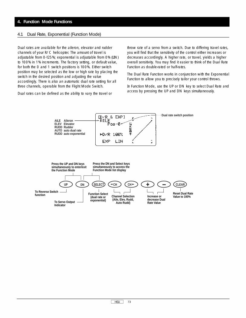
HELI 73
Dual rates are available for the aileron, elevator and rudderchannels of your R/C helicopter. The amount of travel isadjustable from 0-125%; exponential is adjustable from 0% (LIN)to 100% in 1% increments. The factory setting, or default value,for both the 0 and 1 switch positions is 100%. Either switchposition may be selected as the low or high rate by placing theswitch in the desired position and adjusting the valueaccordingly. There is also an automatic dual rate setting for allthree channels, operable from the Flight Mode Switch.
Dual rates can be defined as the ability to vary the travel or
throw rate of a servo from a switch. Due to differing travel rates,you will find that the sensitivity of the control either increases ordecreases accordingly. A higher rate, or travel, yields a higheroverall sensitivity. You may find it easier to think of the Dual RateFunction as double-rated or half-rates.
The Dual Rate Function works in conjunction with the ExponentialFunction to allow you to precisely tailor your control throws.
In Function Mode, use the UP or DN key to select Dual Rate andaccess by pressing the UP and DN keys simultaneously.
AILE AileronELEV ElevatorRUDD RudderAUTO auto dual rateRUDD auto exponential
Dual rate switch position
4.1 Dual Rate, Exponential (Function Mode)
4. Function Mode Functions
Press the UP and DN keyssimultaneously to enter/exitthe Function Mode
Press the DN and Select keyssimultaneously to access theFunction Mode list display
Increase ordecrease DualRate Value
Channel Selection(Aile, Elev, Rudd,
Auto Rudd)
Reset Dual RateValue to 100%
DN SELECT CH CH CLEARUP
To Reverse Switchfunction Function Select
(dual rate orexponential)To Servo Output
Indicator

HELI 74
When the Automatic Dual Rate function is activated (ACT), whenswitching the Flight Mode switch to Stunt 1 or Stunt 2, or whenswitching the throttle hold switch ON, the Aileron, Elevator, andRudder channel dual rate values can be switched to the valuesset for dual rate position #1. Once the Automatic Dual Ratefunction is selected for a flight mode (1, 2, and/or hold), AUTOwill appear on the D/R screen when the flight mode switch ismoved to the selected position.
Once the Automatic Dual Rate Function has been activated, theword AUTO will appear on the rudder DR/EXP screen.
Automatic Rudder Dual Rate Setting
Typical dual rate settings are as follows:
Dual Rate Switch Position
0 Position (reduced servo travel, for hovering)
1 Position (maximum servo travel, for aerobatics)
Example: 0 position value is set to 80%; 1 position value is setto 100%.
4.2 Automatic Dual Rate, Exponential (Function Mode)
ST1: Flight Mode 1 (Stunt 1)ST2: Flight Mode 2 (Stunt 2)HLD: Throttle Hold (onlyapplicable when throttle hold isactive)
Setting conditionINH: (Inhibit function)ACT: (Activate function)
Press the UP and DN keyssimultaneously to enter/exitthe Function Mode
Press the DN and Select keyssimultaneously to access theFunction Mode list display
Use the + or - toactivate/inhibitAuto D/R
Channel Selection(Press to select
Auto Rudd)
Press to inhibitD/R
DN SELECT CH CH CLEARUP
To Reverse Switchfunction
To Servo OutputIndicator
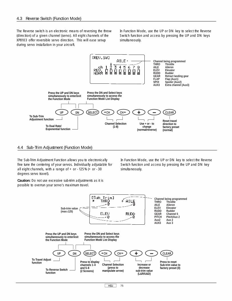
HELI 75
4.4 Sub-Trim Adjustment (Function Mode)
The Sub-Trim Adjustment Function allows you to electronicallyfine tune the centering of your servos. Individually adjustable forall eight channels, with a range of + or - 125% (+ or - 30degrees servo travel).
Caution: Do not use excessive sub-trim adjustments as it ispossible to overrun your servo's maximum travel.
In Function Mode, use the UP or DN key to select the ReverseSwitch function and access by pressing the UP and DN keysimultaneously.
Sub-trim value(max±125)
Channel being programmedTHRO ThrottleAILE AileronELEV ElevatorRUDD RudderGEAR Channel 5PITCH Pitch/Aux 2Aux2 Aux 2AUX3 Aux 3
4.3 Reverse Switch (Function Mode)
The Reverse switch is an electronic means of reversing the throw(direction) of a given channel (servo). All eight channels of theXP8103 offer reversible servo direction. This will ease set-upduring servo installation in your aircraft.
In Function Mode, use the UP or DN key to select the ReverseSwitch function and access by pressing the UP and DN keyssimultaneously.
Channel being programmedTHRO ThrottleAILE AileronELEV ElevatorRUDD RudderGEAR Retract landing gearFLAP Flap (Aux1)SPOI Spoiler (Aux2)AUX3 Extra channel (Aux3)
Press the UP and DN keyssimultaneously to enter/exitthe Function Mode
Press the DN and Select keyssimultaneously to access theFunction Mode List Display
Use + or - tochange
(normal/reverse)
Channel Selection(1-8)
Reset traveldirection tofactory preset(normal)
DN SELECT CH CH CLEARUPTo Sub-TrimAdjustment function
To Dual Rate/Exponential function
Press the UP and DN keyssimultaneously to enter/exitthe Function Mode
Press the DN and Select keyssimultaneously to access theFunction Mode List Display
Increase ordecrease
sub-trim value(L&R/U&D)
Channel Selection(press to
manipulate arrow)
Press to resetSub-trim value tofactory preset (0)
Press to displaychannels 1-4and 5-8(2 Screens)
DN SELECT CH CH CLEARUP
To Travel Adjustfunction
To Reverse Switchfunction

HELI 76
4.5 Travel Adjust (Function Mode)
4.6 Stunt Trim (Function Mode)
The Stunt Trim Function is a trim position setting for aileron,elevator and rudder for use during forward flight maneuvers. Thisfunction is activated when in the flight modes 1 and 2.
Note: When this function is activated, the trim levers of theaileron, elevator and rudder are inactive. Maximum adjustmentrange is approximately 30 degrees.
To adjust the stunt trim, fly your helicopter in a straight line at fullthrottle/pitch in flight mode 1 or 2. Center the elevator stick.Note which direction the helicopter pitches. If the helicopter
pitches up, land the model and add down stunt trim. Repeatuntil no pitching occurs.
Next, check the rudder. Add rudder stunt trim until the tail tracksdirectly behind the helicopter. Finally, adjust the aileron stunt trimin the same manner until no rolling occurs. When properlyadjusted, your helicopter will fly straight and level at full speedwith no correction or trim required.
In Function Mode, use the UP and DN keys to select Stunt Trimand access by pressing the UP and DN keys simultaneously.
Channel being programmedTHRO ThrottleAILE AileronELEV ElevatorRUDD RudderGEAR Channel 5PITCH Pitch/Aux 1AUX2 Aux 2AUX3 Aux 3
Initail setting(inhibit)
Stunt Trim Value(max ± 125)
Arrow indicates channelto be adjusted
CLEARPress CLR key to reset value(at arrow) to zero or to inhibitstunt trim function
Press either + or - key toactivate andIncrease/Decrease value
Press the UP and DN keyssimultaneously to enter/exitthe Function Mode
Press the DN and Select keyssimultaneously to access theFunction Mode List Display
Press to increase ordecrease travel value;move stick or switch tomanipualte arrow to theposition to be adjusted(high/low, left/right)
ChannelSelection
Reset travelvalue to factorypreset (100%)
DN SELECT CH CH CLEARUP
To Stunt Trimfunction
To Sub-Trimfunction
Press to displaychannels 1-4 and5-8 (2 screens)
The purpose of Travel Adjust, also known as endpointadjustment or adjustable travel volume, is to offer you preciseservo control deflection in either direction of servo operation.The travel adjust range is from 0-150% (0 degrees to 60degrees) from neutral and it can be adjusted for each direction
individually. The factory default (data reset) value is 100% foreach direction of servo travel.
In the Function Mode, use the UP or DN key to select the TravelAdjust function and access by pressing the UP and DN keyssimultaneously.

HELI 77
4.7 Throttle Hold (Function Mode)
The Throttle Hold Function holds the throttle servo in a specificposition when the switch is activated. This is very useful forpracticing autorotation landings. The throttle hold switch islocated on the top right corner of the transmitter. The throttle holdfunction is ON in the forward switch position; in the rearposition, the throttle hold function is OFF.
The factory setting for the throttle hold is inhibited. Pressing eitherthe + or - key will adjust the throttle hold value.
Using the + or - key, adjust the throttle hold value to deliver theproper engine RPM for your helicopter. The adjustable range is--20 through +50%. To shut the engine off during anautorotation, a negative value may have to be input.
In Function Mode, use the UP and DN keys to select ThottleHold and access by pressing the UP and DN keyssimultaneously.
4.6 Stunt Trim (Function Mode), cont.
Initail setting(inhibit)
When the Hold switchis in the "ON" position,the display flashes "ON"
CLEARPress CLR key toinhibit the ThrottleHold function
Press either + or - key toactivate andIncrease/Decrease value
or
Throttle Hold PositionValue (-20 – +50%)
ON
Press the UP and DN keyssimultaneously to enter/exitthe Function Mode
Press the DN and Select keyssimultaneously to access theFunction Mode List Display
Press to increase ordecrease the mixingvalue ( ±125%)
Press to reset themixing value at thearrow to the factorypre-set (0) or toinhibit the StuntTrim function
DN SELECT CH CH CLEARUP
To Throttle Holdfunction
To Travel Adjustfunction
Press to movethe arrow to thechannel to beadjusted
Press the UP and DN keyssimultaneously to enter/exitthe Function Mode
Press the DN and Select keyssimultaneously to access theFunction Mode List Display
Press either the +or - keys to set theThrottle Hold value(-20% – +50%)
Press CLR to returnthe Throttle Holdfunction to thefactory pre-setinhibited (Off)position
DN SELECT CH CH CLEARUP
To Throttle Curvefunction
To Stunt Trimfunction

HELI 78
4.8 Throttle Curve (Function Mode)
The XP8103 offers three (3) separate throttle curves with five (5)adjustable points per curve. This function allows you tocustomize the throttle curve and pitch curve together to maximizeengine performance at a particular pitch setting. Once thethrottle curves are established, each can be activated in flightusing the three (3) position flight mode switch. The flight switchoffers three (3) selectable curves. N=Normal, 1=Stunt 1,2=Stunt 2
The N, or Normal, position should be used for hovering.Positions 1 and 2, or Stunt 1 and Stunt 2, should be used foraerobatic maneuvers and forward flight.
Note: The throttle trim and hovering throttle knobs are onlyoperable when the flight mode switch is in the Normal position.Thus, in the 1 or 2 positions, these two functions have no effect.
Each of the five (5) positions of the throttle curve areindependently adjustable from 0 -100%. These five (5) positionscorrespond to the position of the throttle stick.
The transmitter is factory preset to the throttle curve as indicatedby the solid line in the figure below. Individual middle points canbe activated and increased/decreased to suit your specificneeds.
Point output value
Current stick position Existingoutput value
Switch the Flight Modeposition by pressing SEL(Display will flash whenthe flight mode switch isin the same position asdisplayed on the screen)NORM: NormalST-1: Stunt 1ST-2: Stunt 2
CH CHPoint DisplayL: Full low position1: Stick 1/4 position2: Stick center 1/2 position3: Stick 3/4 postionH: Stick full high position
Press either CH key to movethe cursor to each point to beadjusted (L, 1, 2, 3, H)
Press the UP and DN keyssimultaneously to enter/exitthe Function Mode
Press the DN and Select keyssimultaneously to access theFunction Mode List Display
Press the + or - keyto increase/decreaseThrottle Curve valueat the selected point
Press the Clear keyto return the pointvalue at the cursorto the factorypreset, or INHposition.
DN SELECT CH CH CLEARUP
To Pitch Curvefunction
To Throttle Holdfunction
Press the Select key toselect the Throttle Curve tobe adjusted
↓NORM
↓ST 1
↓ST 2
Preset ValuesL: Output Value 0%1: Inhibited2: Output Value 50%3. InhibitedH: Output Value 100%

HELI 79
4.8 Throttle Curve (Function Mode), cont.
Throttle Trim Setting
The throttle trim lever is only active when the flight mode switchis in the normal position. The throttle trim is used to increase ordecrease the engine RPM to achieve a reliable idle when in theNormal Mode. The throttle trim lever has no effect at position 1,2, Stunt 1 or Stunt 2, or throttle hold.
Hovering Throttle Knob Setting
The hovering throttle knob increases or decreases the engineoutput power for either the center point only (point #2), ormiddle three (3) points, if activated, of the throttle curve. Asshown in the figures below, use of the hovering throttle knobshifts the middle curve upward or downward. Therefore,operation of the hovering throttle knob does not cause anychange to the high point and low point of the throttle curve.
Hovering Throttle Knob
The hovering throttleknob adjusts all middlepoints that are activatedin Normal Mode
Operating Range
Throttle TrimOperatingRange
Point L
Throttle StickLow High
Output value
(Points 1 and 3)
Hovering Throttle Knob
When points 1, 2, & 3are activated, theHovering Throttle Knobwill increase/decreaseall 3 points together
Operating Range
Throttle TrimOperatingRange
Point L
Throttle StickLow High
Output value
(all points areparallel)
CLEAR
Middle Pointfactory pre-set at 50%
INH means that this point iscurrently inhibited
Throttle Point ExamplesInactivated Point #1
Activated Point #1
Middle point 1 is activated (output value = 25%)
When a particular point isactivated, the output valuewill then be displayed
Press the Clear key to returnthe point value at the cursor tothe factory preset, or INHposition
Press either the + or - keysto activate and adjust thepoint shown at the cursor
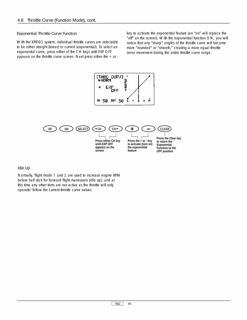
HELI 80
Press the + or - keyto activate (turn on)the exponentialfeature
Press either CH keyuntil EXP OFFappears on thescreen
Press the Clear keyto return theExponentialFunction to theOFF position
DN SELECT CH CH CLEARUP
Idle Up
Normally, flight mode 1 and 2 are used to increase engine RPMbelow half stick for forward flight maneuvers (idle up), and atthis time any other trims are not active as the throttle will onlyoperate/follow the current throttle curve values.
Exponential Throttle Curve Function
With the XP8103 system, individual throttle curves are selectableto be either straight (linear) or curved (exponential). To select anexponential curve, press either of the CH keys until EXP OFFappears on the throttle curve screen. Next press either the + or -
key to activate the exponential feature (an “on” will replace the“off” on the screen). With the exponential function ON, you willnotice that any “sharp” angles of the throttle curve will becomemore “rounded” or “smooth,” creating a more equal throttleservo movement during the entire throttle curve range.
4.8 Throttle Curve (Function Mode), cont.

HELI 81
Adjustment of the pitch curve is very similar to the throttle curveadjustment described in the preceding section. A thoroughunderstanding of the throttle curve section will make pitch curveadjustment easier to understand.
The XP8103 offers four (4) independent types of pitch curves:Normal, Stunt 1, Stunt 2 and Hold. Each pitch curve containsfive (5) adjustable points — L, 1, 2, 3, and H. Note: Whensetting pitch curve for throttle hold, it is necessary for the throttlehold to be active — if this function is inhibited, the throttle holdpitch curve will not be visible on the screen.
In the Function Mode, use the UP and DN keys to select PitchCurve and access by pressing the UP and DN keyssimultaneously.
Hovering Pitch Knob
The hovering pitch knob operates in the same manner as thehovering throttle knob. It is operable while the flight mode is inthe N, or Normal, position, and its function is to shift either thecenter point only (#2) or the middle three (3) points (if activated)of the curve either upward or downward to adjust rotor RPM atthe hover position.
Pitch Trim Knob
The pitch trim knob is a trimmer for the pitch channel. This knobshould be set to 0, and all changes upward or downwardshould be made from this neutral point. This function is used toadjust the main rotor speed (RPM) to stay within manufacturer’sspecifications. If the pitch curve is set properly, only small trimadjustments will be required.
4.9 Pitch Curve (Function Mode)
Point DisplayL. Full low position1. Stick 1/4 position2. Stick center 50% position3. Stick 3/4 postionH: Stick full high position
CH CH
When a particularpoint is activated,the output value willthen be displayed
Current stickposition
Existingoutput value
Switch the Flight Modeposition by pressing SEL(Display will flash when theflight mode switch is in thesame position as displayedon the screen)NORM: NormalST-1: Stunt 1ST-2: Stunt 2HOLD: Throttle Hold
Press either CH key tomove the cursor to eachpoint to be adjusted(L, 1, 2, 3, H)
Press the UP and DN keyssimultaneously to enter/exitthe Function Mode
Press the DN and Select keyssimultaneously to access theFunction Mode List Display
Press the + or - keyto increase/decreasePitch Curve value atthe selected point
Press either CHkey to move thecursor to eachpoint to beadjusted (L, 1, 2, 3, H, EXP)
Press Clear toreturn the pointvalue at the cursorto the factorypreset, or INHposition.
DN SELECT CH CH CLEARUP
To Inverted Switchfunction
To Throttle Curvefunction
(Only when ThrottleHold function isactivated)
Press the Select keyto select the PitchCurve to beadjusted
↓NORM
↓ST 1
↓ST 2
↓HOLD
Preset ValuesL: Output Value 0%1: Inhibited2: Output Value 50%3. InhibitedH: Output Value 100%

HELI 82
Example of Throttle Curve and Pitch Curve Settings
An example of throttle curve and pitch curve settings foraerobatic specifications are shown below in the form of graphs.
Details of the curves will differ, depending on the helicopterspecifications. In these examples, the throttle open-close strokeand autorotation pitch stroke are set from 0 to 100.
4.9 Pitch Curve (Function Mode), cont.
Loop &Stall Turn
Roll
Autorotation
Stunt Mode/Aerobatic Throttle/Pitch Curve Examples
Point L
Output Value
Point L
Output Value
Point L
Output Value
Point L
Output Value
Point L
Output Value
Throttle Curve Pitch Curve
Point L
HoveringManeuvers
Normal Mode/Hover Throttle/Pitch Curve Examples
Output Value
Point L
Output Value
▼
▼

HELI 83
The purpose of the Inverted Switch Function is to electronicallyreverse several control directions to enable you to fly ahelicopter much more easily inverted. When the invertedswitch is pulled down, the inverted flight function is switchedON. When this function is not in use, the display shows INH asbelow. If you do not intend to use the inverted function, leavethis operation inhibited.
In the Function Mode, use the UP and DN keys to select InvertedSwitch and access by pressing the UP and DN keyssimultaneously.
Inverted Flight Offset Value
This inverted point is the throttle position at which no collectivepitch change will take place when the inverted flight function isoperated. The higher the value, the further the throttle/collectivestick must be positioned toward the full throttle position. The
factory preset is 50%, and it is actually somewhat less thanhover throttle since the inverted flight function is normallyoperated with the stick toward the lower throttle position.
When the inverted flight function is activated, collective, rudderand elevator operations are reversed automatically. For invertedhovering maneuvers, the flight mode switch should be left in theN, or Normal, position. For inverted aerobatic maneuvers, it isrecommended that you set up a pitch curve dedicated toinverted flight. This is most often used in conjunction with flightmode, switch position 2.
The throttle curve is operated as a preset curve selected by theflight mode switch and does not affect inverted or normal flight.
Note: The Throttle Hold Function, when activated, has priorityover the inverted or flight mode switches.
Refer to the illustrations below to understand the offset values forinverted flight.
As shown above, when the offset value is set for 50%, theinverted flight pitch curve is exactly opposite from the normalpitch curve settings. If the offset is adjusted to a lesser value, say
35%, the entire pitch curve is lower (relative to the control stick)as shown. Use caution when selecting the correct amount ofoffset as an inadequate pitch range could result.
4.10 Inverted Switch (Function Mode)
Initail setting(inhibit)
When the Inverted Switch is inthe ON postion, display flashes"ON"
CLEARPress the CLR key to inhibitthe Inverted Switch function
Press either the + or - keysto activate and Increase/Decrease the offset value
or
ON
The Pitch Curve factoryoffset value (50%) isadjustable from 0-100%
Inverted Flight Offset Values
Operating RangeNormal curve line
Offset 50% line(Pitch Curve exactly opposite)
Offset 35% line

HELI 84
The Revolution Mixing Function mixes tail rotor input with theThrottle/Collective Function to counteract torque from the mainrotor blades. When set-up correctly, the helicopter should climband descend without a tendency to yaw in either direction.Because torque reaction varies with different power settings, it isnecessary to vary the tail rotor pitch at the same time. TheXP8103 offers two (2) separate revolution mixing programs withindependent up and down mixing for each — one for flightmode position N and the other for Stunt 1 and Stunt 2 positions.The U, or Up, mixing adjusts the tail rotor compensation for themid to high throttle/stick setting, and the D, or Down, mixingadjusts the tail rotor compensation for the mid to lowthrottle/stick setting.
In the Function Mode, use the UP and DN keys to selectRevolution Mixing and access by pressing the UP and DN keyssimultaneously.
Setting Up Revolution Mixing
First, adjust the helicopter so that it will hover in a neutralposition with the tail rotor trim at center. Next, establish thehelicopter into a stable hover; then steadily increase the throttleto initiate a stable climb. The body of the helicopter will move inthe opposite direction to the main rotor rotation. Increase the U,or Up, setting until the helicopter will climb with no tendency toturn or rotate. At a safe altitude, close the throttle and thehelicopter will descend with the body turning in the samedirection as the main rotor. Increase the D, or Down, mix untilthe helicopter descends with no tendency to turn or rotate.When attempting this procedure, throttle stick movements shouldbe slow, and the initial acceleration and deceleration swingsshould be overlooked.
4.11 Revolution/Acceleration Mixing (Function Mode)
4.10 Inverted Switch, (Function Mode) cont.
mixing values
Press either CH keyto move the arrow to theposition to be activated:NORM NormalUP UpDN DownSTNT StuntUP UpDN Down
CH CH
Once a mixing value has beenentered, either an "L" or "R" willappear on the screen: "L" is forleft revolution mixing "R" is forright revolution mixing
Press the UP and DN keyssimultaneously to enter/exitthe Function Mode
Press the DN and Select keyssimultaneously to access theFunction Mode List Display
Press the + or - keysto increase/decreasethe offset value
Press to inhibit theInverted SwitchFunction
DN SELECT CH CH CLEARUP
To Revolution/AccelerationMixing Function
To Pitch Curvefunction
Press the UP and DN keyssimultaneously to enter/exitthe Function Mode
Press the DN and Select keyssimultaneously to access theFunction Mode List Display
Current Offset Value
Press the + or - key toset the mixing value(L or R, 0% -125%)
Press either CHkey to move thearrow to theposition to beadjusted
Press to resetmixing value tofactory preset (0%) at the arrowposition
DN SELECT CH CH CLEARUP
To Gyro Sensitivityfunction
To Inverted Switchfunction
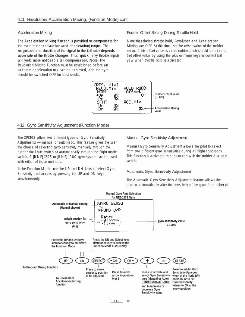
HELI 85
4.12 Gyro Sensitivity Adjustment (Function Mode)
The XP8103 offers two different types of Gyro SensitivityAdjustments — manual or automatic. This feature gives the userthe choice of selecting gyro sensitivity manually through therudder dual rate switch or automatically through the flight modeswitch. A JR NEJ-120S or JR NEJ-1000 gyro system can be usedwith either of these methods.
In the Function Mode, use the UP and DN keys to select GyroSensitivity and access by pressing the UP and DN keyssimultaneously.
Manual Gyro Sensitivity Adjustment
Manual Gyro Sensitivity Adjustment allows the pilot to selectfrom two different gyro sensitivities during all flight conditions.This function is activated in conjunction with the rudder dual rateswitch.
Automatic Gyro Sensitivity Adjustment
The Automatic Gyro Sensitivity Adjustment feature allows thepilot to automatically alter the sensitivity of the gyro from either of
4.11 Revolution/Acceleration Mixing, (Function Mode) cont.
Rudder Offset Value( ± 125)
Acceleration MixingValue
Manual Gyro Rate Selectionfor NEJ-120S Gyro
gyro sensitivity value 0-100%
Automatic or Manual setting(Manual shown)
switch postion forgyro sensitivity
(0-1)
Acceleration Mixing
The Acceleration Mixing function is provided to compensate forthe main rotor accelaration (and deceleration) torque. Themagnitude and duration of the signal to the tail rotor dependsupon rate of the throttle changes. Thus, quick, jerky throttle inputswill yield more noticeable tail compensation. Note: TheRevolution Mixing Function must be established before anaccurate acceleration mix can be achieved, and the gyroshould be switched OFF for best results.
Rudder Offset Setting During Throttle Hold
Note that during throttle hold, Revolution and AccelerationMixing are OFF. At this time, set the offset value of the rudderservo. If this offset value is zero, rudder pitch should be at zero.Set offset value by using the plus or minus keys to correct tailyaw when throttle hold is activated.
100%0%
Press the UP and DN keyssimultaneously to enter/exitthe Function Mode
Press the DN and Select keyssimultaneously to access theFunction Mode List Display
Press to activate andselect Gyro Sensitivitytype (Manual or Auto)→INH→Manual →Autoand to increase ordecrease GyroSensitivity value
Press to movearrow to position0 or 1
Press to inhibit GyroSensitivity Functionwhen at the Rudd D/Rposition, or to setGyro Sensitivityvalues to 0% at thearrow position
To Program Mixing Function
To Revolution/Acceleration Mixingfunction
Press to movecursor to positionto be adjusted

HELI 86
two pre-determined settings through the use of the flight modeswitch. As different flight modes are selected (Normal, 1, 2,Hold), the Gyro’s sensitivity rate will switch to the pre-determinedcompensation rate for each particular flight mode in use.
Gyro Installation/Adjustment
JR NEJ-120S Gyro
Gyro Sensitivity Adjustment
Manual Gyro Sensitivity Adjustment
1. Connect the white connector from the NEJ-120S gaincontroller to the AUX 2 channel of the receiver.
2. Select the manual gyro sensitivity feature (RUDD D/R willappear on the XP8103 screen).
3. Adjust the 0 position under the RATE on the display to 100%and the 1 position to 0% using the + or - keys.
4. Adjust the gyro sensitivity for positions 0 and 1 on theNEJ-120S gain controller.
5. Move the Rudder D/R switch from the low position to thehigh position with the gyro ON to verify that it is functioningproperly, and note the “high/low” sensitivity values relative tothe dual rate switch. Refer to the NEJ-120S gyro instructions forfurther information.
Automatic Gyro Sensitivity Adjustment
1. Connect the white connector from the NEJ-120S gaincontroller to the AUX 2 channel of the receiver.
2. Select the Automatic Gyro Sensitivity Adjustment Feature(“AUTO” will appear on the screen).
3. Adjust the 0 position under the RATE on the display to 100%and the 1 position to 0% using the + or - keys.
4. Under Function Mode select the gyro rate (position #1 orPosition #0) that you wish to be active in each flight mode.
5. Turn the system ON and move the flight mode switch to its 3positions with the gyro ON to verify that it is functioningproperly. Refer to the NEJ-120S gyro instructions for furtherinformation.
4.12 Gyro Sensitivity Adjustment (Function Mode) cont.
Automatic or Manualrate selection
(automatic shown)
Automatic Gyro Sensitivity Selection
Flight Mode Rate Selection:NORM: NormalSTNT: StuntHOLD: Throttle Hold (when activated)INVT: Inverted (when activated)
Press the UP and DN keyssimultaneously to enter/exitthe Function Mode
Press the DN and Select keyssimultaneously to access theFunction Mode List Display
Press to activate andselect Gyro Sensitivitytype (Manual or Auto)→INH→Manual →Autoand to increase ordecrease GyroSensitivity value forNEJ 1000 Note: For NEJ120, setthe 0 position at 100%and 1 postiion at 0%
Press to movearrow to rateposition 0 or 1and to selectrate values forflight modes
Press to inhibit GyroSensitivity when at theAuto position, or toset Gyro Sensitivityvalues to 0% at thearrow position
DN SELECT CH CH CLEARUP
To Program Mixing Function
To Revolution/Acceleration Mixingfunction
Press to movecursor to positionto be adjusted

HELI 87
JR NEJ-1000 Piezo Gyro
Manual Gyro Sensitivity Adjustment
1. Connect the white connector from the NEJ-1000 remote gaincontroller to the AUX 2 channel of the receiver.
2. Select the Manual Gyro Sensitivity Feature (“RUDD D/R” willappear on the screen).
3. Adjust the gyro sensitivity values for the 0 and 1 positionsfrom the screen of the XP8103. (Generally, 0 position is used forthe lower sensitivity value, with position 1 used for the highervalue.)
4. Turn the system ON and move the Rudder D/R switch fromthe low to high position with the gyro ON to verify that it isfunctioning properly and to note the ‘high/low” sensitivity valuesrelative to the dual rate switch. Refer to the NEJ-1000 gyroinstructions for further information.
Automatic Gyro Sensitivity Adjustment
1. Connect the white connector from the NEJ-1000 remote gaincontroller to the AUX 2 channel of the receiver.
2. Select the Automatic Gyro Sensitivity Adjustment Feature(“AUTO” will appear on the screen).
3. Adjust the gyro sensitivity values for the 0 and 1 positionsfrom the screen of the XP8103. (Generally, 0 position is used forthe lower sensitivity value, with position 1 used for the highervalue.)
4. Select the compensation values for each of the four flightmode positions from the XP8103 screen (Normal, 1, 2, Hold).
5. Turn the system ON and move the flight mode switch to its 3positions with the gyro ON to verify that it is functioningproperly. Refer to the NEJ-1000 gyro instructions for furtherinformation.
The XP8103 offers three programmable mixes that can be usedfor any number of different purposes. Mixes #1 and #2 featurea 5-point programmable mixing system with graphic display,while the 3rd mix is of the standard 3-point variety. This functionallows mixing any one channel to any other channel to make theaircraft easier to fly. This mix can be set in the computer andremain on at all times, or it can be switched on and off in flightusing a number of different switches. The channel appearing firstis known as the master channel, or the channel to which youwant to mix. The second channel is known as the slave channel,or the channel that is being mixed into the previous channel.
For example, aileron to rudder mix would indicate that the first(aileron) channel is the “master,” with the second (rudder)channel acting as the “slave.” Therefore, each time the aileronstick is moved, the aileron will deflect, and the rudder willautomatically move in that direction and to the value input.Mixing is proportional, so small inputs of the master channel willproduce small outputs of the slave channel. Each programmablemix has a mixing “offset.” The purpose of the mixing offset is toredefine the neutral position of the slave channel.
Mixing 1 and 2 are freely programmable curve mixing at any 5points of the master channel. The figure on the following pageshows Mix 1 is inhibited.
Programmable Mix #1 and #2 Channel Selection
As mentioned, programmable mixes #1 and #2 are of the multi-point variety, allowing the use of up to 5 adjustable points tovary or “curve” the mix for precise adjustment. Diagram #1below shows Mix #1 in the inhibited position. To activate mix#1, press either the + or - key. After the mix has been activated,press either the + or - keys to select the first, or master, channelto be mixed. Next, press either of the CH keys to move theunderlined cursor to the right. Then press either the + or - keys toselect the second, or slave, channel to be mixed.
Operational Switch Settings
The programmable mixes can be turned on and off in flightusing a variety of different switches. The chart below lists theindication seen on the LCD display and its definition:
4.13 Programmable Mixing 1-3 (Function Mode)
Program Mix #1 Switch Settings
ON On at all times
F-NR On at flight mode switch at normal position
F-S12 On at flight mode stunt #1 and stunt #2 positions
F-S2 On at flight mode stunt #2 position
4.12 Gyro Sensitivity Adjustment, (Function Mode) cont.

HELI 88
4.13 Programmable Mixing 1-3 (Function Mode), cont.
Programmable Mix #1 (Inhibited)
Press the UP and DN keyssimultaneously to enter/exitthe Function Mode
Press the DN and Select keyssimultaneously to access theFunction Mode List Display
Press either + or - keyto activate the Mixfunction
Press either CHkey to program theMaster/Slavechannels, or tomove the cursor toany of the 5 points(L, 1, 2, 3,H)
Press to inhibit (INH)the Mix function, or toreset a point at thecursor to 0
DN SELECT CH CH CLEARUP
To Program Mixing #2
To Gyro SensitivityAdjustment function
Press SEL key tomove cursor aftermix has beenactivated
To select the desired switch setting, press the SEL key twice tomove the cursor to the SW position on the LCD screen. Next,press either the + or - keys to select the desired switch setting.
Mixing Point Adjustment
The 5-point Programmable Mixing Function found inprogrammable mixes #1 and #2 allows you to manipulate oneor all of the point values to create a non-linear “curve” of the
second, or slave, servo output. Adjustment of this curve onlyaffects the second, or slave, channel and has no effect on theservo output of the first, or master, channel. Points 1 and 3 areinhibited, or inactive, until the user has input a value to theparticular mixing point.
To adjust the points, press the SEL key until the cursor is in linewith the “Point L” as indicated on the LCD display. Next, presseither CH key to select the point to be adjusted.
To change the value of the selected point, press either the + or -key. The input value for the point being adjusted will be visibleunder the “Point” portion of the LCD display. Both stick input andservo output values will be shown at the lower left portion of theLCD display.
Note: The servo output value will not be displayed on the screenunless the operational switch selected is in the proper position toactivate the programmable mixing function.
Program Mix #2 Switch Settings
On On at all times
Hold On at throttle hold position
F-S12 On at flight mode stunt #1 and stunt #2 positions
Gear On at gear/inverted switch “on” position

HELI 89
Programmable Mix #3
Programmable Mix #3 is similar to the previous mixes, with theexception that there are only 3 positions where output valuescan be adjusted.
As in the previous mixes, the first channel is considered themaster channel, with the second channel selected as the slavechannel.
This mix can be set in the computer and remain on at all times,or it can be switched on and off in flight using a number ofdifferent switches.
Programmable Mix #3 uses a high and low mixing valueadjustment, as well as a mixing offset value to redefine theneutral position of the slave channel.
Programmable Mix #1 & #2
Point number (L, 1, 2, 3, H)Master channel
Control stick input value Mix point to be adusted
Slave channel
Channel displayTHRO: ThrottleAILE: AileronELEV: ElevatorRUDD: RudderGEAR: Channel 5PIT: Pitch/Aux 1AUX 2: Aux 2AUX 3: Aux 3
Mixing value (max ± 100)
Mixing switch type selected (ON, F-NR, F-S12, F-S2)Mixing value of existing stick postition
4.13 Programmable Mixing 1-3 (Function Mode), cont.
Press the UP and DN keyssimultaneously to enter/exitthe Function Mode
Press the DN and Select keyssimultaneously to access theFunction Mode List Display
Press either + or - keyto select theMaster/Slave channels,to turn exponential Onor Off, and to selectthe Mixing Switch type
Press either CHkey to program theMaster/Slavechannels, or tomove the cursor toany of the 5 points(L, 1, 2, 3,H)
Press to reset thevalue to the factorypreset at the cursor
DN SELECT CH CH CLEARUP
To Program Mixing #1
To Gyro SensitivityAdjustment function
Press to movecursor aftermix has beenactivated
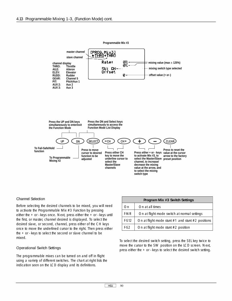
HELI 90
Channel Selection
Before selecting the desired channels to be mixed, you will needto activate the Programmable Mix #3 Function by pressingeither the + or - keys once. Next, press either the + or - keys untilthe first, or master, channel desired is displayed. To select thedesired slave, or second, channel, press either of the CH keysonce to move the underlined cursor to the right. Then press eitherthe + or - keys to select the second or slave channel to bemixed.
Operational Switch Settings
The programmable mixes can be turned on and off in flightusing a variety of different switches. The chart at right lists theindication seen on the LCD display and its definitions.
To select the desired switch setting, press the SEL key twice tomove the cursor to the SW position on the LCD screen. Next,press either the + or - keys to select the desired switch setting.
4.13 Programmable Mixing 1-3, (Function Mode) cont.
Program Mix #3 Switch Settings
On On at all times
F-NR On at flight mode switch at normal settings
F-S12 On at flight mode stunt #1 and stunt #2 positions
F-S2 On at flight mode stunt #2 position
Press the UP and DN keyssimultaneously to enter/exitthe Function Mode
Press the DN and Select keyssimultaneously to access theFunction Mode List Display
Press either + or - keysto activate Mix #3, toselect the Master/Slavechannel, to increase/decrease the mixingvalue at the arrow, andto select the mixingswitch type
Press either CHkey to move theunderline cursor toselect theMaster/Slavechannels
Press to reset thevalue at the cursorarrow to the factorypreset position
DN SELECT CH CH CLEARUP
To Fail-Safe/Holdfunction
To ProgrammableMixing #2
Press to movecursor to desiredfunction to beadjusted
Programmable Mix #3
master channel
slave channel
channel displayTHRO: ThrottleAILE: AileronELEV: ElevatorRUDD: RudderGEAR: Channel 5PIT: Pitch/Aux 1AUX 2: Aux 2AUX 3: Aux 3
mixing value (max ± 125%)
mixing switch type selected
offset value (+ or -)

HELI 91
The Fail-Safe/Hold Function is available only when you use theXP8103 transmitter in either of the PCM modulations — S-PCMor Z-PCM. This function is designed to help minimize damage toyour airplane during a loss of signal to the receiver. The servoseither assume the fail-safe presets or hold the last good signalposition.
Note: In the PCM modulations, the Fail-Safe/Hold Functioncannot be totally disabled so that the servos will react tointerference in the same way as they do in a PPM system. This isonly possible with the use of a PPM receiver and the transmitterin the PPM modulation.
Note: Since the actual screen appearance varies, depending onthe modulation of your radio, refer to the appropriatemodulation section which follows (Z-PCM, S-PCM).
As noted earlier, if you are in the PPM modulation, the Fail-Safe/Hold Function is not applicable. Therefore, the Fail-Safe/Hold Function will not appear on your LCD in the PPMmode.
Refer to the Modulation Selection Section for more informationpertaining to the broadcast signal of your XP8103 transmitter.
Accessing the Fail-Safe/Hold Function in Z-PCM Modulation
Hold (Z-PCM)
The Hold Function is automatically activated when the radio isturned ON and is in the Z-PCM modulation.
This function stops (or holds) the servos in the positions they werein just prior to the interference. Therefore, your airplanemaintains the position held immediately before the interferencewas experienced. When a clear signal is restored, the HoldFunction releases, and control of the airplane returns to you.
1. Place the transmitter power switch in the ON (upper)position.
2. While the power switch is in the ON position, press the UPand DN keys simultaneously to access the Function Mode.
3. Press either the UP or DN key until Fail-Safe appears in theleft portion of your LCD.
Note: If Fail-Safe does not appear on your LCD, it is becauseyou are transmitting in PPM. Fail-Safe is not applicable in thePPM mode. Refer to the Modulation Mode Selection Section formore information.
Rate Adjustment
The Rate Adjustment Function found in the Programmable Mix#3 Function allows you to increase or decrease the amount ofmixing (servo travel) given to the slave channel in either thehigh/low, or left/right positions. Adjustment of this value willonly affect the mixing value (output) of the slave channel, and ithas no effect on the servo output value of the master channel.
To adjust the mixing rate, press the SEL key until the cursor is inline with the “Rate:” as indicated on the LCD display. The arrowshown to the right of the “Rate:” indicates the position to beadjusted. This arrow is manipulated only by the controlstick/switch of the selected master channel. Move the controlstick to bring the arrow to the desired point of adjustment.
Note: The arrow will not be displayed on the screen unless theoperational switch selected is in the proper position to activatethe Programmable Mixing Function.
To adjust the rate value, press either the + or - key until thedesired value has been achieved.
Programmable Mixing Offset
Any position of the master channel can be determined as thebasic point (center) of mixing. The basic point is the position ofthe master channel stick, control switch, or knob where you setthe mix value and the direction of mixing. To set the basic pointof mixing, press the SEL key until the cursor is in line with the“offset” as displayed on the LCD screen. Next, move the masterchannel control stick to the desired position and press the CLR(store) key once to store the offset value. The stored offset valuewill now be displayed at the bottom of the LCD display.
This offset value is the amount of offset value as determined fromneutral. However, the mixing value at the determined positionwill indicate zero.
4.13 Programmable Mixing 1-3 (Function Mode), cont.
4.14 Fail-Safe/Hold
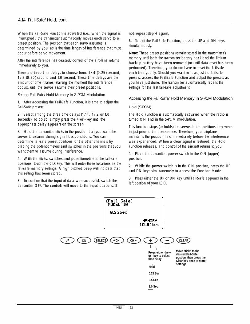
HELI 92
When the Fail-Safe Function is activated (i.e., when the signal isinterrupted), the transmitter automatically moves each servo to apreset position. The position that each servo assumes isdetermined by you, as is the time length of interference that mustoccur before servo movement.
After the interference has ceased, control of the airplane returnsimmediately to you.
There are three time delays to choose from: 1/4 (0.25) second,1/2 (0.50) second and 1.0 second. These time delays are theamount of time it takes, starting the moment the interferenceoccurs, until the servos assume their preset positions.
Setting Fail-Safe/Hold Memory in Z-PCM Modulation
1. After accessing the Fail-Safe Function, it is time to adjust theFail-Safe presets.
2. Select among the three time delays (1/4, 1/2 or 1.0seconds). To do so, simply press the + or - key until theappropriate delay appears on the screen.
3. Hold the transmitter sticks in the position that you want theservos to assume during signal loss conditions. You candetermine fail-safe preset positions for the other channels byplacing the potentiometers and switches in the positions that youwant them to assume during interference.
4. With the sticks, switches and potentiometers in the fail-safepositions, touch the CLR key. This will enter these locations as thefail-safe memory settings. A high pitched beep will indicate thatthis setting has been stored.
5. To confirm that the input of data was successful, switch thetransmitter OFF. The controls will move to the input locations. If
not, repeat step 4 again.
6. To exit the Fail-Safe Function, press the UP and DN keyssimultaneously.
Note: These preset positions remain stored in the transmitter’smemory until both the transmitter battery pack and the lithiumback-up battery have been removed (or until data reset has beenperformed). Therefore, you do not have to reset the fail-safeeach time you fly. Should you want to re-adjust the fail-safepresets, access the Fail-Safe Function and adjust the presets asyou have just done. The transmitter automatically recalls thesettings for the last fail-safe adjustment.
Accessing the Fail-Safe/Hold Memory in S-PCM Modulation
Hold (S-PCM)
The Hold Function is automatically activated when the radio isturned ON and in the S-PCM modulation.
This function stops (or holds) the servos in the positions they werein just prior to the interference. Therefore, your airplanemaintains the position held immediately before the interferencewas experienced. When a clear signal is restored, the HoldFunction releases, and control of the aircraft returns to you.
1. Place the transmitter power switch in the ON (upper)position.
2. While the power switch is in the ON position, press the UPand DN keys simultaneously to access the Function Mode.
3. Press either the UP or DN key until Fail-Safe appears in theleft portion of your LCD.
4.14 Fail-Safe/Hold, cont.
Move sticks to thedesired Fail-Safepostion, then press theClear key once to storesettings
DN SELECT CH CH CLEARUP
Press either the +or - key to selecttime delay
↓Hold
↓0.25 Sec
↓0.5 Sec
↓1.0 Sec

HELI 93
4.14 Fail-Safe/Hold, cont.
Note: If Fail-Safe does not appear on your LCD, it is becauseyou are transmitting in PPM. Fail-Safe is not applicable in thePPM mode. Refer to the Modulation Mode Selection Section formore information.
Fail Safe/Hold Combination in S-PCM Modulation
The XP8103 allows you to combine the hold and fail-safe presetsfor all eight (8) channels on the receiver — you can select fail-safe or hold independently for all channels on your aircraft. Inother words, some channels will hold their last clear signalposition, while others assume the preset position. Once the fail-safe has been activated by signal interruption (interference), thetransmitter automatically moves the servos to a preset position.The predetermined servo positions are set by you. In the S-PCMfail-safe, the time delay (the amount of time it takes, starting themoment the interference occurs, until the servos assume thepreset positions) is fixed at .25, or 1/4, second.
After the interference has ceased, normal operation of theairplane returns to you immediately.
Setting the Fail-Safe/Hold Memory in S-PCM Modulation
1. After accessing the Fail-Safe Function, it is time to adjust thefail-safe presets.
2. Select all of the channels for which you want to enter a fail-safe preset. This is done by pressing the left or right CH keyand moving the cursor arrow over the desired channel. Pressingthe + or - key will cause the particular channel to assume a“hold” or “preset” fail-safe condition which is determined bypositioning the particular control and pressing the CLR key. Thetransmitter will memorize the switch fail-safe position andautomatically transfer the setting to the receiver.
3. Confirmation of proper fail-safe presets/holds is made byturning the transmitter OFF and observing the aircraft’s controlfunctions.
THRO: ThrottleAILE: AileronELEV: ElevatorRUDD: RudderGEAR: Retract gearFLAP: Flap (AUX1)SPOI: Spoiler (AUX2)AUX3: Extra Channel (AUX3)
Channels being programmed
Press the UP and DN keyssimultaneously to enter/exitthe Function Mode
Press the DN and Select keyssimultaneously to access theFunction Mode List Display
Move sticks to desiredFail-Safe position, thenpress the Clear key onceto store settings
DN SELECT CH CH CLEARUP
To Trainer Function
To ProgrammableMixing 6
Press either keyto move arrow todesired channel
Press either the +or - key to selecteither Hold or Fail-Safe positions foreach channel

Normal trainer display
Press the UP and DN keyssimultaneously to enter/exitthe Function Mode
Press the DN and Select keyssimultaneously to access theFunction Mode List Display
Press to reset to factorypreset position (AllMaster)
DN SELECT CH CH CLEARUP
To Timer Function
To Fail-Safe (PCMOnly) or programmablemixing
Press either keyto move arrow todesired channel
Press either the + or -key to select channelsto be activated (Master-Slave) * When all channels areset for Master,condition is set toNormal Trainer
HELI 94
4.15 Trainer (Function Mode)
The XP8103 transmitter employs two separate types of trainersystems:
A. Normal trainer system — all functions are controlled byeither the master transmitter or the slave transmitter.
B. Programmable function trainer — stick functions may beassigned to the slave one at a time. Since the control functionscan be transferred one at a time, students can concentrate ononly one function at a time until they are competent to fly solo.
Basic Connections and Limitations
1. The slave transmitter must be PPM (Pulse Position Modulation)with a DSC (direct servo control) jack. If the slave transmitter isPPM/PCM selectable, select PPM. The master transmitter can beS-PCM, Z-PCM or PPM.
2. Plug the trainer cord into each transmitter’s DSC jack. Noteeach transmitter will appear to be ON, but neither is actuallytransmitting at this time.
3. Switch the master transmitter ON. Do not switch on theslave transmitter; you must only have the master transmitterON.
4. Pull the trainer switch on the Master transmitter toward you totransfer control to the slave. Releasing the switch automaticallyreverts control to the master transmitter.
5. Be sure the slave transmitter servo reversing, dual rates, andpoint adjustment and trims are identical to the master transmitter.This can be checked by pulling the trainer switch toward you. Ifthe control surfaces move, adjust the slave transmitter until thetrainer switch can be activated without a change of the controlsurface position.
A. Using the Normal Trainer System
In this mode, all functions are switched from the master to theslave using the trainer switch. This is the normal mode. Nofunction set-up (reversing switch or travel adjust) is necessary toactivate this system.

HELI 95
4.15 Trainer (Function Mode), cont.
programmable trainer displayChannel display being programmed
If an arrow appears onthe Master transmitterin this position, itindicates the directionthe Slave channel trimlever must be movedon the Slavetransmitter
SLAV: Applicable channel set to SlaveMAST: Applicable channel to Master
The normal display screen will show the typeof trainer function selected once the trainerfunction is activated
B. Use of Programmable Trainer Function
In this mode, the master may assign functions to the student oneat a time to make learning to fly easier. For example, the master
may assign the slave rudder and elevator. Then, when the trainerswitch is activated (pulled toward you), the slave has control ofonly rudder and elevator while the master retains control ofthrottle and aileron.
The XP8103 offers two separate types of timer functions —countdown and stopwatch. In the countdown mode, thetransmitter will beep at 30 seconds. At zero, the time will begincounting up with a + indication. Up count will count up to59:59 (59 minutes 59 seconds).
Count start and stop operations are activated by the snaproll/trainer switch. But when using it as the trainer’s master
transmitter, start/stop by this switch is inhibited.
Accumulated time
Accumulated time is for each model and returns to zero at 100hours. You may use them as individual model’s maintenancehours.
4.16 Timer (Function Mode)

HELI 96
Accumulated timeminuteshours
Countdown timer settingtime (0.00 to 59.50)
Inhibit
Countdown Timer
Stopwatch
Press the UP and DN keyssimultaneously to enter/exitthe Function Mode
Press the DN and Select keyssimultaneously to access theFunction Mode List Display
Press to selecttimer setting:
↓INH
↓Countdown Timer
↓Stopwatch
DN SELECT CH CH CLEARUP
To Servo OutputIndicator
To Trainerfunction
Press either keyto move arrow
Press to inhibitTimer function orto set Integ-Tvalue to 0
Or to increase or decreasecountdown timer settings
NORMAL DISPLAY w/down timer function selected
Timer setting time
Press to movecursor from timerto Integ-T
Press to reset timer tozero (0)
DN SELECT CH CH CLEARUP
Press either keyto start/stop timer
4.16 Timer (Function Mode), cont.

HELI 97
This function displays each servo’s operating value. Each barcenter indicates neutral position. Left or right dots indicate 50%,100% and 150%.
Note: All indications are actual positions including adjustmentsand mixing. It is also possible to view servo travel/servodirections when mixing functions are activated.
4.17 Servo Output Indicator (Function Mode)
50%100%150%
ATV Travel
Press the UP and DN keyssimultaneously to enter/exitthe Function Mode
Press the DN and Select keyssimultaneously to access theFunction Mode List Display
DN SELECT CH CH CLEARUPTo Dual RateExponential function
To Timerfunction

HELI 98
EXP L 1 2 3 H
N OFF•ON % % % % %
1 OFF•ON % % % % %
2 OFF•ON % % % % %
N OFF•ON % % % % %
1 OFF•ON % % % % %
2 OFF•ON % % % % %
N OFF•ON % % % % %
1
XP8103 DATA SHEET HELIMODEL NO. ____________________________________
MODEL NAME __________________________________
MODULATION SPCM - ZPCM - PPM ________________
AILE ELEV RUDD
D/R % % %
EXP % % %
D/R % % %
EXP % % %
0
0 %
%
%
POS
OFFSET
REVOMIX
ACC MIX
NORMAL
NORM
STNT
HOLD
INVT
UP %
DOWN %
UP %
DOWN %
%
GYROSENS
INH•
RUDD D/R•
AUTO
STUNT
PROGRAMMIX
HOLD RUDD OFFSET%
THROTTLECURVE
PITCHCURVE
STUNT TRIM INH • ACT
THRO HOLD INH • ACT
THRO HOLD INH • ACT
CHANNEL SW EXP L 1 2 3 H
MIX1 → OFF-ON
MIX2 → OFF-ON
+POS -POS OFFSET
MIX3 → % %
REVERSE SW
SUB TRIM
TRAVEL ADJUST
FAIL SAFE (SPCM)
THRO AILE ELEV RUDD GEAR PIT AUX2 AUX3
NORM NORM NORM NORM NORM NORM NORM NORM• • • • • • • •
REV REV REV REV REV REV REV REV
H % L % D % L % + % H % + % + %
L % R % U % R % - % L % - % - %
DUAL-RATE•
EXP
AUTOD/R
(POS. 1)
ST1 INH • ACT
ST2 INH • ACT
ST2 INH • ACT
AUX2 HOLD SW• PIT.TRIM•INH
GEAR ACT • INH
INPUTSEL
1

GLID 99
V. Glider Section
Important: Before installing your servos in your glider's wing,see page 134, Servo Installation Section.
Note: The Practical Application Section on page 134 provides astep-by-step procedure on programming a 5 or 6 servoequipped glider. Reference to this section is highlyrecommended prior to setting up your glider.

GLID 100
1. Transmitter Controls
1.1 Control Identification and Location
Channel Assignment/Throttle ALT
Channel # TX Function Airplane Function1 Spoi Spoiler Channel 2 Ail 1 Left Aileron Channel (AIL1)3 Elev Elevator Channel4 Rudd Rudder Channel5 Ail 2 Right Aileron Channel (AIL 2)6 Flap Left Flap Channel for Dual Flaps7 Aux 2 Right Flap Channel for Dual Flaps8 Aux 3 Auxillary 3 Channel
Throttle ALT
This function makes the spoiler stick trim active only when thespoiler stick is at less than 50%, which allows for fine adjustmentof the spoilers with the spoiler stick in the lower position.
Input Keys
Aileron Trim
Elevator Trim
Aileron/Elevator Stick
Antenna
Aux 2 Flapron Flap Trim Knob(Pot #5)
Carrying Handle
LCD Display (Do Not Press)
Flap Trim Knob (Pot #6)
Aileron Dual Rate Switch
Rudder Dual Rate Switch
Mixing Switch
Power Switch
Rudder Trim
Spoiler Trim
Neck Strap Eyelet
Timer Trainer Switch
Dual Flap/AileronTrim Knob (Pot #7)
Elevator Dual Rate Switch
Crow Switch
Spoiler/Rudder Stick
Flap Mixing Switch▲ Reflex■ Off▼ Launch

Pitch Trim Knob
Trainer/Timer Switch
Invert Switch
Elevator Dual Rate Switch
Flight Mode Switch
Throttle Trim
Throttle/Rudder Stick
Neck Strap Eyelet
Rudder Trim
Power Switch
Input Keys
Aileron Trim
Aileron/Elevator StickElevator Trim
Hovering Throttle Knob
Aileron Dual Rate Switch
Rudder Dual Rate Switch
Throttle Hold Switch
Carrying Handle
LCD Display –DO NOT PRESS
Antenna
Hovering Pitch Knob
N-Normal Position1-Flight Mode 12-Flight Mode 2
GLID 101
Aux 2 Knob
Snap Roll/Timer/Trainer Switch
Gear Switch
Elevator Dual Rate Switch
Flap/Mixing Switch
Throttle Trim
Throttle/Rudder Stick
Neck Strap Eyelet
Rudder Trim
Power Switch
Input Keys
Aileron Trim
Aileron/Elevator StickElevator Trim
Flap Knob
Aileron Dual Rate Switch
Rudder Dual Rate Switch
P. Mix Switch/Aux 2
Carrying Handle
LCD Display –DO NOT PRESS
Antenna
Aux 3 Knob
Channel Assignment
Channel Assignment
Airplane Version Transmitter–Airplane Mode
Airplane Version Transmitter–Heli Mode
1. THRO Throttle Channel 2. AILE Aileron Channel 3. ELEV Elevator Channel 4. RUDD Rudder Channel 5. GEAR Gear Channel 6. AUX 1 Auxiliary 1 Channel (Flap)7. AUX 2 Auxiliary 2 Channel (Spoiler)8. AUX 3 Auxiliary 3 Channel
1. THRO Throttle Channel 2. AILE Aileron Channel 3. ELEV Elevator Channel 4. RUDD Rudder Channel 5. GEAR Gear Channel 6. AUX 1 Auxiliary 1 Channel (Pitch)7. AUX 2 Auxiliary 2 Channel
(Gyro Sensitivity)8. AUX 3 Auxiliary 3 Channel

GLID 102
1.2 Connections
Aux Channel
Aux Channel
Spoiler Channel
Flap Channel
RetractGear Channel
Deluxe Switch Harness(JRPA001)
Charge Cord orDSC Receptacle
(JRPA024)
72
NER-649SS-PCM Receiver
(JRPR649)PCM Version
NER-549SFM Receiver(JRPR549)FM Version
4N6004.8V 600mAh
JAPAN REMOTE CONTROL CO., LTD.
®
notused
AUX3
AUX2/Flap(Right)
AUX1/Flap(Left)
AileronRight
RUDD
ELEV
AILE (Left)
Spoilers

GLID 103
• You will hear a clicking (beeping) sound to confirm input hasbeen achieved.
• Except for the CLEAR key, the AUTO advance system (twospeed scrolling) is active when you continue pressing down ona key.
• The SEL keys or CH keys are used to scroll through, ormanipulate functions within a specific program or display.
2.1 Input Key Functions
Function Selection keys(press both keyssimultaneously to enter orexit the function mode)
Normal Display Screen
transmitter voltagemodel number
modulation typemodel name (whennames are entered)
integrated timer
Press both keys simultaneouslyto access the system mode orfunction mode lists.
used for changing pages orindicated displays
used for channel changes in themodel set-up and function modes
Data Entry Keys
Up KeyDown Key Select Key Channel Key Increase Key Decrease Key
Clear Key
2.2 Normal Display
2. General Information
SELECT L /+ R/- CLEAR

GLID 104
To set the System Set-Up Mode, press the UP and DN keyssimultaneously and turn the power switch from OFF to ON.Functions are selectable by pressing either the DN or UP keys.Individual settings are explained later at each function. In thismode, servos are not activated, but operating signals are
transmitting (only when the Tx module is in place). However, useextra caution not to interfere with other frequencies. By pressingthe DN and UP keys simultaneously, you can return to the normaldisplay, which allows the servos to again operate.
3.1 System Set-Up Mode
3. System Set-Up Mode Functions
Pg. 106 Information Display
Pg. 106 Model Select And Copy Function
Pg. 107 Model Name Input
Pg. 108 Model Type Selection Function
Pg. 108 Data Reset
Pg. 109 Modulation Selection
Pg. 110 Model Data Transfer
Pg. 112 Wing Type Selection
Pg. 112 Flap Channel Input Selection
SYSTEM SET-UP MODE
[INFO-DISP]
↕
2.2 Normal Display, cont.
DN SELECT CH CH CLEARUP
Press simultaneouslyto access the ListMode/System Set-Up Mode
Press Select andeither the + or - keyssimultaneously toadjust the contrast ofthe LCD display
Press the Clear keyto reset to factorysettingsPress the UP and DN keys
simultaneously to changeto Function Mode (withpower switch ON)
When timer function isactive, use CH key tostart/stop timer
Press the UP and DN keyssimultaneously and switch thepower from OFF to ON tochange the system to theSystem Set-Up Mode
From the Normal Display, the following inputs can be made:
When setting various functions with the buttons shown below,start either in the Function Mode or the System Set-Up Mode.
Use either the UPor DN key to scrollthrough the menuand access theapplicable function
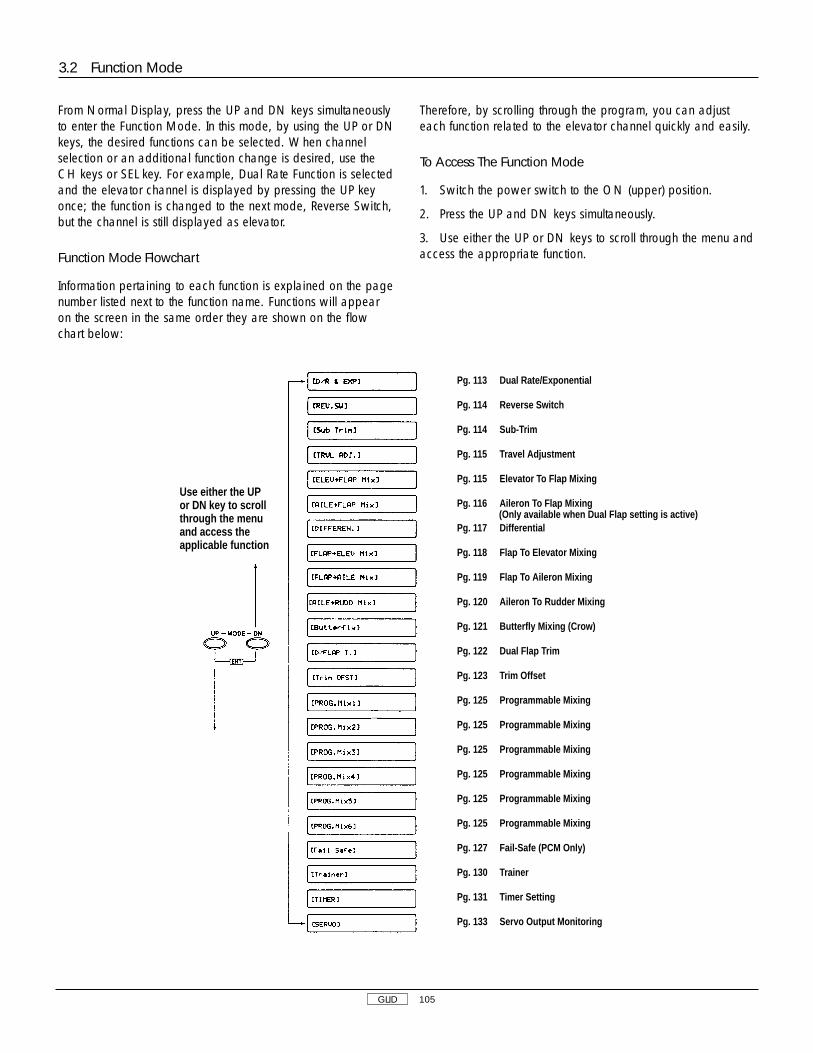
GLID 105
From Normal Display, press the UP and DN keys simultaneouslyto enter the Function Mode. In this mode, by using the UP or DNkeys, the desired functions can be selected. When channelselection or an additional function change is desired, use theCH keys or SEL key. For example, Dual Rate Function is selectedand the elevator channel is displayed by pressing the UP keyonce; the function is changed to the next mode, Reverse Switch,but the channel is still displayed as elevator.
Function Mode Flowchart
Information pertaining to each function is explained on the pagenumber listed next to the function name. Functions will appearon the screen in the same order they are shown on the flowchart below:
Therefore, by scrolling through the program, you can adjusteach function related to the elevator channel quickly and easily.
To Access The Function Mode
1. Switch the power switch to the ON (upper) position.
2. Press the UP and DN keys simultaneously.
3. Use either the UP or DN keys to scroll through the menu andaccess the appropriate function.
3.2 Function Mode
Pg. 113 Dual Rate/Exponential
Pg. 114 Reverse Switch
Pg. 114 Sub-Trim
Pg. 115 Travel Adjustment
Pg. 115 Elevator To Flap Mixing
Pg. 116 Aileron To Flap Mixing
Pg. 117 Differential
Pg. 118 Flap To Elevator Mixing
Pg. 119 Flap To Aileron Mixing
Pg. 120 Aileron To Rudder Mixing
Pg. 121 Butterfly Mixing (Crow)
Pg. 122 Dual Flap Trim
Pg. 123 Trim Offset
Pg. 125 Programmable Mixing
Pg. 125 Programmable Mixing
Pg. 125 Programmable Mixing
Pg. 125 Programmable Mixing
Pg. 125 Programmable Mixing
Pg. 125 Programmable Mixing
Pg. 127 Fail-Safe (PCM Only)
Pg. 130 Trainer
Pg. 131 Timer Setting
Pg. 133 Servo Output Monitoring
(Only available when Dual Flap setting is active)
Use either the UPor DN key to scrollthrough the menuand access theapplicable function

GLID 106
3.4 Model Select (System Set-Up Mode)
The XP8103 transmitter employs a memory function whichmemorizes data for up to 10 individual aircraft. All settingsalong with type selection, function, and different aircraft areused by one transmitter. For example, Model 1 is helicopter andModel 2 is airplane. To avoid confusing models, inputing model
names for each aircraft is recommended (see page 107). Pressthe UP and DN keys simultaneously and turn the power switchON to access the System Set-Up Mode.
The display below shows the model selection function.
To enter the List Mode, press the DN and SEL keyssimultaneously. From this display, pressing the UP and DN keyssimultaneously will move the system from the list mode to the
function shown at the cursor. Note that the cursor is moved bythe UP and DN keys.
3.3 List Mode (Function Mode)
DN SELECT CH CH CLEARUP
DN SELECT CH CH CLEARUP
Press simultaneouslyto access function atcursor
Press UP and DN keyssimultaneously to enter/exitthe System Set-Up Mode
model number (1-10)
type
modulation
model name(if dot is shown, modelname is blank)
To Model Name function
To Info Display function
Function select (select model/copy) Model selection
(1-10)
Press UP and Select keyssimultaneously to access theSystem Mode info display
Press to select either oftwo Function List screens
Inactive while in List Mode screen

GLID 107
3.5 Copy Select Function (System Set-Up Mode)
The Copy Select Function enables you to copy all of the settingsof your current model to another memory (model number) within
the same transmitter. This is very useful when setting up oneaircraft several different ways.
3.6 Model Names (System Set-Up Mode)
This function is used to input model names individually. Eachmodel’s name is displayed in the normal screen automatically.when that model is selected. To avoid confusing models,inputing model names is recommended. You can input a
maximum of 8 characters for each model name.
In the System Set-Up Mode, select the Model Name functionusing the UP or DN key. Once selected, simultaneously press theUP and DN keys to access.
DN SELECT CH CH CLEARUP
Press UP and DN keyssimultaneously to enter/exitthe System Set-Up Mode
Press the Select key toaccess the copy functionin Model Select mode
To Model Name function
To Spoiler Channel inputselection function
Function select (select model/copy) Model selection —
use to select modelto be copied to
Activate copyfunction
Model names(if dot is shown,model name is blank)Existing model
number
Model to becopied to
DN SELECT CH CH CLEARUP
Press UP and DN keyssimultaneously to enter/exitthe System Set-Up Mode
Press the DN and Select keyssimultaneously to access thesystem mode info display
To Model Type Selectionfunction
To model select/copyfunction
Press to changeinput letter at arrow
Press to changeinput letter arrowposition
Changes input letterto blank space onlywhere arrow islocated
Model typeModel number
Modulation Letter position beinginputed (8 characters)

GLID 108
3.8 Data Reset (System Set-Up Mode)
The Data Reset Function allows you to reset all the functions andsettings for the current model to the factory pre-set conditions.Resetting does not affect the data already programmed for othermodels. Be sure to confirm that you need to reset the data of thecurrently indicated model in order to prevent accidental loss ofvaluable data.
Note: If a model name has been input and is reset, the modelname will not be removed, only the data. Please refer to theModel Name Function for information on how to change themodel's name.
To access Data Reset, select Model Reset in System Set-Up andpress the UP and DN keys simultanelously.
3.7 Model Type Selection (System Set-Up Mode)
The XP8103 is capable of performing as a helicopter, airplaneor glider radio with full functions for each.
It can also memorize data for 10 models individually.
Note: If the power switch is turned OFF immediately afterselecting the new model type, the change will not be saved.To change and save the model type press the UP or DN keys, orpress UP and DN keys or DN and SEL keys simultaneously. Atthis time, existing model data is replaced by the model typeaircraft data selected. Be sure to confirm the model name to
prevent accidental loss of your important data. To cancel thisfunction, return to former model type or turn the power switchOFF.
Note: When you select helicopter or airplane model type on thistransmitter, allocation of lever switches, etc., will also change.Please refer to the helicopter or airplane section of this instructionmanual for their functions.
In System Set-Up Mode, select the Type Select Function andsimultaneously press the UP and DN keys to access
DN SELECT CH CH CLEARUP
Press simultaneously tochange and save modeltype
Press the DN and Select keyssimultaneously to access thesystem mode info display
To Data Reset function
To Model Name function
Press to move arrowand select modeltype
DN SELECT CH CH CLEARUP
Press simultaneously toexit the System Set-UpMode
To Modulation Selectfunction
To Model Type Selectfunction
Press to return tofactory preset data
model number tobe reset
Model numberModel name (if blank,no model name hasbeen stored)Helicopter
Airplane
GliderArrow indicatesexisting modeltype

GLID 109
In system Set-Up Mode, select Modulation Select using the UPand DN keys and press the UP and DN keys simultaneously toaccess.
3.9 Modulation Select (System Set-Up Mode)
The Modulation Selection Function enables your XP8103 totransmit to a variety of JR receivers that are already, or may soonbe, in existence. You can select from either S-PCM or Z-PCMmode, depending on the Central Processing Unit within yourreceiver, or from PPM (Pulse Position Modulation—FM). Refer tothe receiver compatibility chart for the correct modulation.
Caution: After making modulation changes, you must presseither the UP and DN, or the DN and SEL keys simultaneously toaccept the new modulation type. If the Tx power switch is turnedOFF before this procedure, the modulation change will not besaved.
Tx Modulation Compatible # of Channels Receivers & Brief Description
PPM (FM) NER-226 6 (micro)PPM (FM) NER-228 8PPM (FM) NER-327x 7PPM (FM) NER-527x 7 (micro)PPM (FM) NER-529x 9 (micro)PPM (FM) NER-549 9PPM (FM) NER-600 6 (micro)
Tx Modulation Compatible # of Channels Receivers & Brief Description
Z-PCM NER-236 6 (micro)Z-PCM NER-627XZ or
627 “G” series 7Z-PCM NER- J329P 9Z-PCM NER-910XZ 10S-PCM NER-D940S 10S-PCM NER-649S 9
Receiver Compatibility Chart
Modulationselection SPCM,ZPCM, or PPM(FM)
DN SELECT CH CH CLEARUP
Press the UP and DN keys or DN andSelect keys simultaneously toaccept the new modutation type andto exit the System Set-Up Mode
Press the DN and Select keys toaccept the new modulation and toaccess the system info display
To Data Transferfunction
Model Number
To Data Resetfunction
Reset modulationto SPCM
ModulationModel Type

GLID 110
CLR start transmitting
transmitting counter(0-100%)
make sure that the receivingmode transmitter (Tx to beprogrammed) is in the stand-bycondition.
Transfer Procedure
1. Select the model number to be transferred (transmitting modeside) through the Model Select Function. (See page 106 forinformation on Model Select Function.)
2. Both transmitters: With the power switches OFF, press the UPand DN keys simultaneously while inserting the trainer cord intothe DSC jacks of both transmitters.
3. Both transmitters: Select the Transfer Fuction by pressing theUP or DN key. Then simultaneously press the UP and DN keys toenter the Transfer Function.
4. Receiving mode transmitter (Tx to be programmed): Press theSelect key until the screen reads "Receive." Select the receivingmodel number by pressing the + or - keys. Next, press the CLRkey to activate the receiving stand-by mode.
5. Transmitting mode transmitter (Tx with program to betransferred): Press the CLR key to start transmitting data. Bothtransmitters will indicate [End ok!] display when the transmittingis complete.
3.10 Data Transfer (System Set-Up Mode)
This function is used to transfer all existing memorized data for amodel from one XP8103 transmitter to another XP8103 transmitter.
Use the + and - keys to select models to be transferred andactivate by pressing the CLR key.
To avoid the loss of important data, re-confirm model nameswhen transferring.
Caution: Please use special caution when copy function isactivated as existing data is replaced with new data.
Caution: When the battery alarm is activated (battery low), thecopy function is not operational.
Transmitting mode
Model number
Display indicates DSC cord isnot connected, or Tx powerswitch is on/off
Press + or -keys to selectmodels to betransferred
Press + or -keys to selectthe receivingmodel number
DN SELECT CH CH CLEARUP
Press the UP and DN keyssimultaneously to enter/exit theSystem Set-Up Mode
Press the DN and Select keyssimultaneously to access theSystem Mode info display
To Wing TypeSelection function
To ModulationSelect function
SelectTransmitting/Receiving Mode
Press to starttransmittingdata
DN SELECT CH CH CLEARUP
To Wing TypeSelection function
To ModulationSelect function
Transmitting/Receiving Modeselect

GLID 111
existing model number
CLR key to startstand-by receiving
+ or - to select models
model number tobe copy Receiving counter (0-100%)
When there is a data receiving failure during transmitting, thecounter will stop. At this time, press the CLR key to stop thereceiving condition. Check to be sure the receiving counter isoperating normally and ended with 100%. If there is any failure
of transferring, the display will appear as follows:
3.10 Data Transfer, cont.
stand-bycondition
receivingcounter0-100%
stand-by receiving condition
To Wing TypeSelection function
To ModulationSelect function
DN SELECT CH CH CLEARUP
Transmitting/Receivingmode select Press to start
transmitting
When the receiving counter is stopped or you see ERRORindicated, check the DSC cord connections or trainer cordconditions and try again. When data has been receivedcorrectly, you will see [End ok!] display. Be sure that thereceiving mode transmitter is in stand-by condition first. Then onthe transmitting transmitter press the CLR key to start transmitting.
Also ensure that when transferring is complete, previous datastored in the receiving side transmitter is replaced by the newdata transferred.
Note: This function does not work when the battery alarm isflashing (low battery).
Receivingmodel select
Press to standbyreceiving/stopreceiving condition
DN SELECT CH CH CLEARUP
To Wing TypeSelection function
To ModulationSelect function
Transmitting/Receiving Modechange

GLID 112
Setting condition
Function now beingprogrammed
Press + or -key to inhibitor activatefunction
Press to resetto INH
DN SELECT CH CH CLEARUP
To Flap Channel InputSelection function
To Model DataTransfer function
Press eitherCH key toselect V-Tailor Dual Flap
3.11 Wing Type Selection (System Set-Up Mode)
3.12 Input Selection (System Set-Up Mode)
Use of V-Tail
Connect the left moveable tail surfaces to the servo connected toELEV and the right moveable tail surfaces to the servo connectedto RUDD. At this time, the servo’s operational value isautomatically set for 75%. An applicable channel’s servo travel isindividually adjusted by each servo’s dual rate settings. Servoreversing is also set individually. Neutral adjustment should bemade individually using the Sub-Trim Adjustment Function.
Use of Dual Flap
Connect the left flap to channel 6 (FLAP) and the right flap to the
servo connected to channel 7 (AUX 2) of the receiver. At thistime, the Aileron to Flap Mixing Function is available for setting,and by using the POT (dual flap aileron trim knob), both flapsare operational as trim for aileron operations.
Applicable channel’s servo travel and reversing switches neutraladjustment should be made individually using the Sub-TrimAdjustment Function. This setting is very useful and allows the leftand right ailerons and both flaps to operate as flaps or ailerons.
Connect the right aileron to channel 5 (AUX2); the left flap isconnected to channel 6 (FLAP), the left aileron to channel 2(AILE), and the right flap is servo connected to channel 7(AUX 2).
At this time, activate dual flaps using the Flap Channel InputSelection for FLP.SW + P6 (flap switch and flap POT set for trimoperations).
The following mixes are now available:
• flap to elevator mixing
• flap to aileron mixing
• aileron to flap mixing
• butterfly mixing
FLAP (6-ch) and AUX 2 (7-ch) servo travel can be adjusted byChannel 7's travel adjust operational value.
Trim adjustment for each control surface can be adjusted by the
following POTs: POT-5 for aileron’s flap trim, POT-6 for flap’s flaptrim, POT-7 for flap’s aileron trim
Flap channel input is selectable either by flap knob (POT-6) orflap switch. POT-6 also operates as the trim.
Selection is made by pressing either the + or - keys (POT-6—-FLP.SW + P6). Press the CLR key to preset to POT-6.
• When POT-6 is selected, the servo is 100% operational by theflap knob.
• When FLP.SW+P6 is selected, flap operation is activated withthe spoiler stick (throttle stick).
• Flap servo travel adjustment is achieved with Flap TravelAdjustment.
Press the UP and DN keyssimultaneously to enter/exitthe System Set-Up Mode
Press the DN and Select keyssimultaneously to access theSystem Mode info display

GLID 113
3.12 Input Selection, cont.
Dual rates are available for the aileron, elevator and rudderchannels of your R/C glider. The amount of travel is adjustablefrom 0-125%; exponential is adjustable from 0% (LIN) to 100% in1% increments. The factory setting, or default value, for both the0 and 1 switch positions is 100%. Either switch position may beselected as the low or high rate by placing the switch in thedesired position and adjusting the value accordingly.
Dual rates can be defined as the ability to vary the travel orthrow rate of a servo from a switch. Due to differing travel rates,
you will find that the sensitivity of the control either increases ordecreases accordingly. A higher rate, or travel, yields a higheroverall sensitivity. You may find it easier to think of the Dual RateFunction as double-rated or half-rates.
The Dual Rate Function works in conjunction with the ExponentialFunction to allow you to precisely tailor your control throws.
In Function Mode, use the UP or DN key to select Dual Rate andaccess by pressing the UP and DN keys simultaneously.
AILE AileronELEV ElevatorRUDD Rudder
Dual rate switch position
4.1 Dual Rate, Exponential (Function Mode)
4. Function Mode Functions
Press the UP and DN keyssimultaneously to enter/exitthe Function Mode
Current Flap Channel InputPot 6: Flap Knob FLP.SW+PG: Flap Switch
and Pot 6
Press the DN and Select keyssimultaneously to access theFunction Mode list display
Increase ordecrease DualRate Value
Channel Selection(Aile, Elev, Rudd,
Auto Rudd)
Reset Dual RateValue to 100%
DN SELECT CH CH CLEARUP
To Reverse Switchfunction Function Select
(Dual Rate orExponential)To Servo Output
Indicator
Press either the+ or - key toselect Pot 6 orFLP.SW +P6
Press to resetFlap input toPot 6
DN SELECT CH CH CLEARUP
To Model Selectfunction
To Wing Type function
Press the UP and DN keyssimultaneously to enter/exitthe System Set-Up Mode
Press the DN and Select keyssimultaneously to access theSystem Mode info display

GLID 114
The Sub-Trim Adjustment Function allows you to electronicallyfine tune the centering of your servos. Individually adjustable forall eight channels, with a range of + or - 125% (+ or - 30degrees servo travel).
Caution: Do not use excessive sub-trim adjustments as it ispossible to overrun your servo's maximum travel.
In Function Mode, use the UP or DN key to select the Sub TromAdjustment Mixing function and access by pressing the UP andDN keys simultaneously.
4.2 Reverse Switch (Function Mode)
The Reverse Switch is an electronic means of reversing the throw(direction) of a given channel (servo). All eight channels of theXP8103 offer reversible servo direction. This will ease set-upduring servo installation in your aircraft.
In Function Mode, use the UP or DN key to select the ReverseSwitch function and access by pressing the UP and DN keyssimultaneously.
Press the UP and DN keyssimultaneously to enter/exitthe Function Mode
Channel being programmedSPOI SpoilerAIL1 AileronELEV ElevatorRUDD RudderAIL2 Right AileronFLAP Flap (Left)AUX2 Flap (Right)AUX3 Extra Channel (Aux3)
Press the DN and Select keyssimultaneously to access theFunction Mode List Display
Use + or - tochange
(normal/reverse)
Channel Selection(1-8)
Reset traveldirection tofactory preset(normal)
DN SELECT CH CH CLEARUPTo Sub-TrimAdjustment function
To Dual Rate/Exponential function
Sub-Trim value(max ± 125)
4.3 Sub-Trim Adjustment (Function Mode)
Press the UP and DN keyssimultaneously to enter/exitthe Function Mode
Press the DN and Select keyssimultaneously to access theFunction Mode List Display
Increase ordecrease
sub-trim value(L&R/U&D)
Channel Selection(press to
manipulate arrow)
Press to resetSub-trim value tofactory preset (0)
Press to displaychannels 1-4and 5-8(2 Screens)
DN SELECT CH CH CLEARUP
To Travel Adjustfunction
To Reverse Switchfunction
Channel being programmedSPOI SpoilerAILE1 AileronELEV ElevatorRUDD RudderAILE2 Right AileronFLAP Flap (Left)AUX2 Flap (Right)AUX3 Extra channel (Aux3)
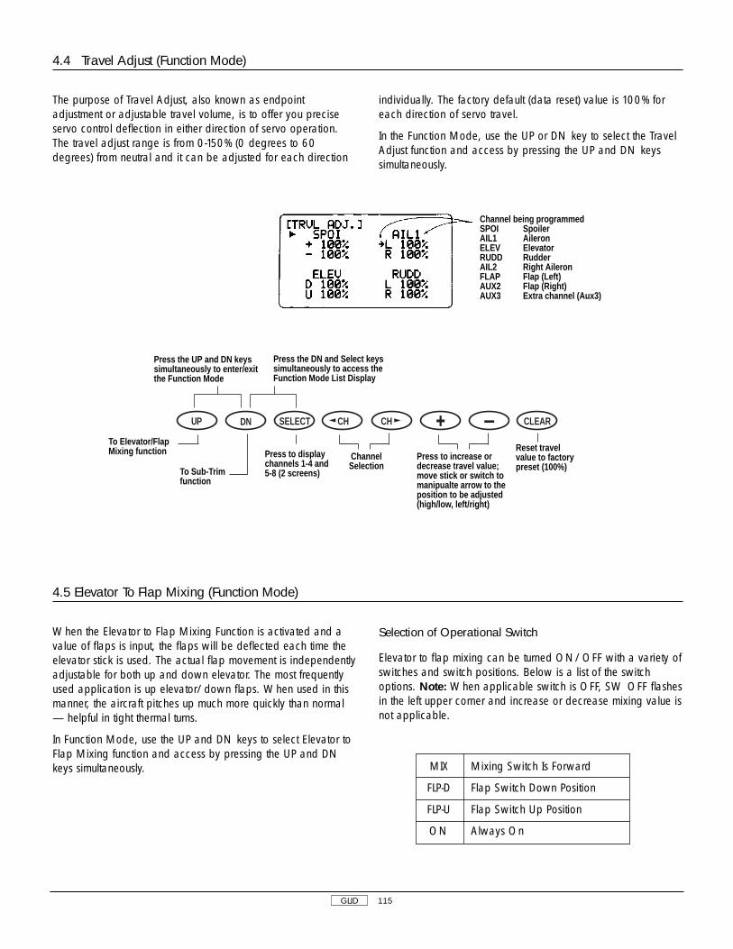
GLID 115
4.4 Travel Adjust (Function Mode)
The purpose of Travel Adjust, also known as endpointadjustment or adjustable travel volume, is to offer you preciseservo control deflection in either direction of servo operation.The travel adjust range is from 0-150% (0 degrees to 60degrees) from neutral and it can be adjusted for each direction
individually. The factory default (data reset) value is 100% foreach direction of servo travel.
In the Function Mode, use the UP or DN key to select the TravelAdjust function and access by pressing the UP and DN keyssimultaneously.
4.5 Elevator To Flap Mixing (Function Mode)
When the Elevator to Flap Mixing Function is activated and avalue of flaps is input, the flaps will be deflected each time theelevator stick is used. The actual flap movement is independentlyadjustable for both up and down elevator. The most frequentlyused application is up elevator/down flaps. When used in thismanner, the aircraft pitches up much more quickly than normal— helpful in tight thermal turns.
In Function Mode, use the UP and DN keys to select Elevator toFlap Mixing function and access by pressing the UP and DNkeys simultaneously.
Selection of Operational Switch
Elevator to flap mixing can be turned ON/OFF with a variety ofswitches and switch positions. Below is a list of the switchoptions. Note: When applicable switch is OFF, SW OFF flashesin the left upper corner and increase or decrease mixing value isnot applicable.
Press the UP and DN keyssimultaneously to enter/exitthe Function Mode
Press the DN and Select keyssimultaneously to access theFunction Mode List Display
Press to increase ordecrease travel value;move stick or switch tomanipualte arrow to theposition to be adjusted(high/low, left/right)
ChannelSelection
Reset travelvalue to factorypreset (100%)
DN SELECT CH CH CLEARUP
To Elevator/FlapMixing function
To Sub-Trimfunction
Press to displaychannels 1-4 and5-8 (2 screens)
Channel being programmedSPOI SpoilerAIL1 AileronELEV ElevatorRUDD RudderAIL2 Right AileronFLAP Flap (Left)AUX2 Flap (Right)AUX3 Extra channel (Aux3)
MIX Mixing Switch Is Forward
FLP-D Flap Switch Down Position
FLP-U Flap Switch Up Position
ON Always On
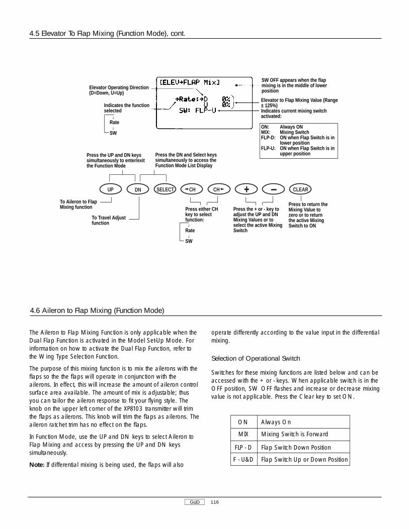
4.6 Aileron to Flap Mixing (Function Mode)
The Aileron to Flap Mixing Function is only applicable when theDual Flap Function is activated in the Model Set-Up Mode. Forinformation on how to activate the Dual Flap Function, refer tothe Wing Type Selection Function.
The purpose of this mixing function is to mix the ailerons with theflaps so the the flaps will operate in conjunction with theailerons. In effect, this will increase the amount of aileron controlsurface area available. The amount of mix is adjustable; thusyou can tailor the aileron response to fit your flying style. Theknob on the upper left corner of the XP8103 transmitter will trimthe flaps as ailerons. This knob will trim the flaps as ailerons. Theaileron ratchet trim has no effect on the flaps.
In Function Mode, use the UP and DN keys to select Aileron toFlap Mixing and access by pressing the UP and DN keyssimultaneously.
Note: If differential mixing is being used, the flaps will also
operate differently according to the value input in the differentialmixing.
Selection of Operational Switch
Switches for these mixing functions are listed below and can beaccessed with the + or - keys. When applicable switch is in theOFF position, SW OFF flashes and increase or decrease mixingvalue is not applicable. Press the Clear key to set ON.
GLID 116
Press the UP and DN keyssimultaneously to enter/exitthe Function Mode
SW OFF appears when the flapmixing is in the middle of lowerposition
Elevator Operating Direction(D=Down, U=Up)
Indicates the functionselected
Elevator to Flap Mixing Value (Range ± 125%)Indicates current mixing switchactivated:
ON: Always ONMIX: Mixing SwitchFLP-D: ON when Flap Switch is in
lower positionFLP-U: ON when Flap Switch is in
upper positionPress the DN and Select keyssimultaneously to access theFunction Mode List Display
Press the + or - key toadjust the UP and DNMixing Values or toselect the active MixingSwitch
Press either CHkey to selectfunction: ↓
Rate↓
SW
Press to return theMixing Value tozero or to returnthe active MixingSwitch to ON
DN SELECT CH CH CLEARUP
To Aileron to FlapMixing function
To Travel Adjustfunction
4.5 Elevator To Flap Mixing (Function Mode), cont.
ON Always On
MIX Mixing Switch is Forward
FLP - D Flap Switch Down Position
F - U&D Flap Switch Up or Down Position
↓Rate↓
SW

GLID 117
4.6 Aileron to Flap Mixing (Function Mode), cont.
Press the UP and DN keyssimultaneously to enter/exitthe Function Mode
SW OFF appears when the Flap Mixing is inthe middle or lower postition
Aileron to Flap Mixing Value (Range ± 125%)
Indicates current Mixing Switch activated:
Press the DN and Select keyssimultaneously to access theFunction Mode List Display
At rate, press toincrease/decreaseMixing Value (± 125%)At Switch, press tochange SwitchSelection
Press either CHkey tomanipulate thearrow fromRATE to SW
At rate, press toset Mixing value tofactory preset (0%)At Switch, press toset Switch tofactory preset (ON)
DN SELECT CH CH CLEARUPTo Differential AileronMixing function
To Elevator to FlapMixing function
ON: Always ONMIX: Mixing SwitchFLP-D: ON when Flap Switch is in
lower positionFLP-U: ON when Flap Switch is in
upper position
4.7 Differential Aileron Mixing (Function Mode)
The XP8103 transmitter offers aileron differential. Differentialailerons are used to tailor the flight control system to a particularaircraft. Because the downward travel of the aileron createsmore drag than the upward travel, it is necessary to reduce theamount of down travel for each aileron. This drag may very wellproduce an adverse yawing tendency in your aircraft. Asadverse yaw is undesirable in most, if not all, R/C aircraft, it isbest to correct for this common flight tendency. Aileron
differential overcomes this yaw as it reduces the downwardtravel of the ailerons.
In Function Mode, use the UP and DN keys to select DifferentialAileron Mixing and access by pressing the UP and DN keyssimultaneously.
Note: Differential may also be obtained by using the traveladjust.
Indicates thefunction beingselected:↓
Rate↓
SW
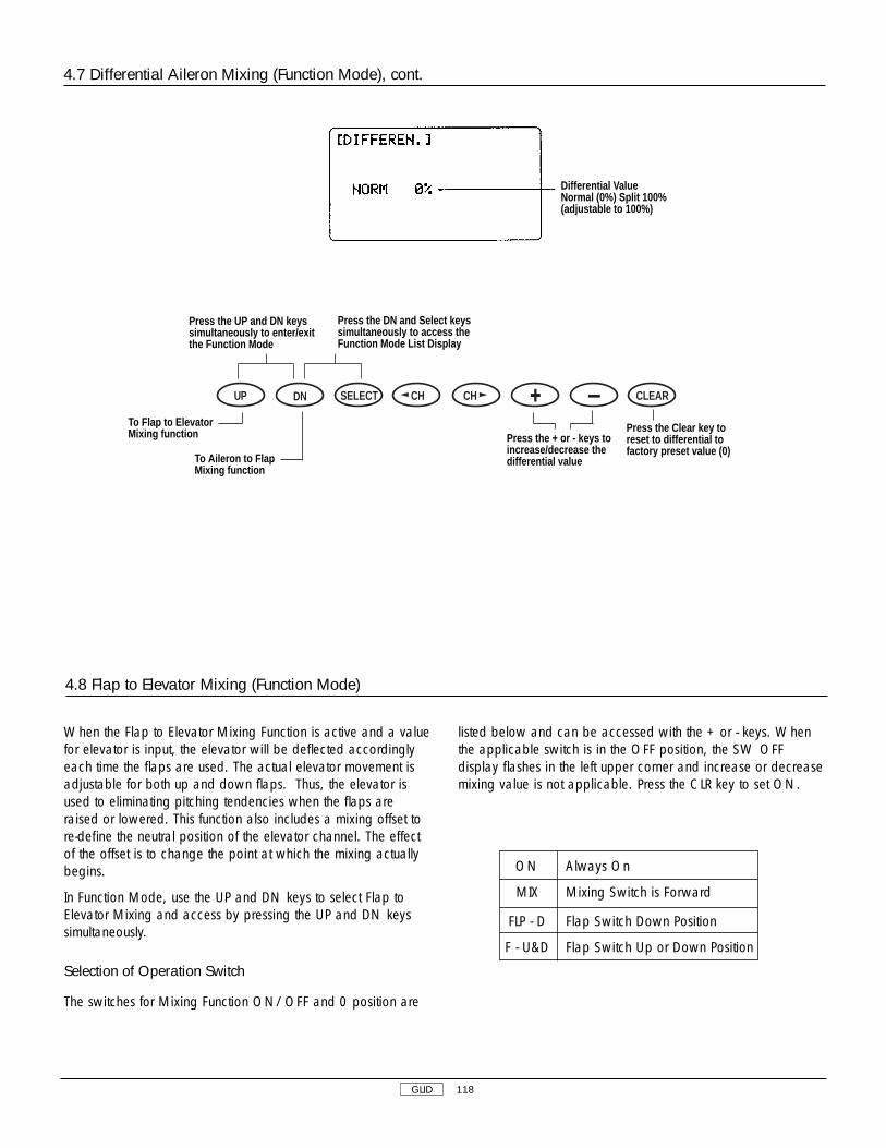
GLID 118
When the Flap to Elevator Mixing Function is active and a valuefor elevator is input, the elevator will be deflected accordinglyeach time the flaps are used. The actual elevator movement isadjustable for both up and down flaps. Thus, the elevator isused to eliminating pitching tendencies when the flaps areraised or lowered. This function also includes a mixing offset tore-define the neutral position of the elevator channel. The effectof the offset is to change the point at which the mixing actuallybegins.
In Function Mode, use the UP and DN keys to select Flap toElevator Mixing and access by pressing the UP and DN keyssimultaneously.
Selection of Operation Switch
The switches for Mixing Function ON/OFF and 0 position are
listed below and can be accessed with the + or - keys. Whenthe applicable switch is in the OFF position, the SW OFFdisplay flashes in the left upper corner and increase or decreasemixing value is not applicable. Press the CLR key to set ON.
Differential ValueNormal (0%) Split 100% (adjustable to 100%)
4.8 Flap to Elevator Mixing (Function Mode)
Press the UP and DN keyssimultaneously to enter/exitthe Function Mode
Press the DN and Select keyssimultaneously to access theFunction Mode List Display
Press the + or - keys toincrease/decrease thedifferential value
Press the Clear key toreset to differential tofactory preset value (0)
DN SELECT CH CH CLEARUP
To Flap to ElevatorMixing function
To Aileron to FlapMixing function
4.7 Differential Aileron Mixing (Function Mode), cont.
ON Always On
MIX Mixing Switch is Forward
FLP - D Flap Switch Down Position
F - U&D Flap Switch Up or Down Position
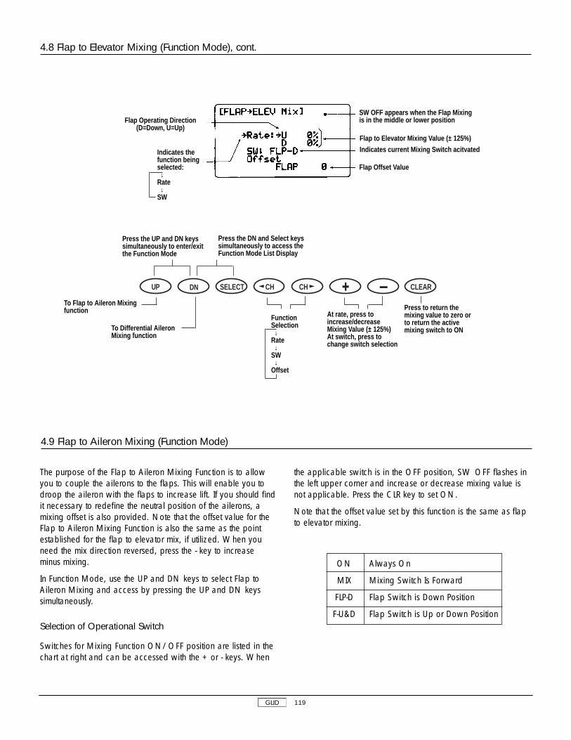
The purpose of the Flap to Aileron Mixing Function is to allowyou to couple the ailerons to the flaps. This will enable you todroop the aileron with the flaps to increase lift. If you should findit necessary to redefine the neutral position of the ailerons, amixing offset is also provided. Note that the offset value for theFlap to Aileron Mixing Function is also the same as the pointestablished for the flap to elevator mix, if utilized. When youneed the mix direction reversed, press the - key to increaseminus mixing.
In Function Mode, use the UP and DN keys to select Flap toAileron Mixing and access by pressing the UP and DN keyssimultaneously.
Selection of Operational Switch
Switches for Mixing Function ON/OFF position are listed in thechart at right and can be accessed with the + or - keys. When
the applicable switch is in the OFF position, SW OFF flashes inthe left upper corner and increase or decrease mixing value isnot applicable. Press the CLR key to set ON.
Note that the offset value set by this function is the same as flapto elevator mixing.
ON Always On
MIX Mixing Switch Is Forward
FLP-D Flap Switch is Down Position
F-U&D Flap Switch is Up or Down Position
4.8 Flap to Elevator Mixing (Function Mode), cont.
4.9 Flap to Aileron Mixing (Function Mode)
Flap Operating Direction(D=Down, U=Up)
SW OFF appears when the Flap Mixingis in the middle or lower position
Flap to Elevator Mixing Value (± 125%)
Indicates current Mixing Switch acitvated
Flap Offset Value
Press the UP and DN keyssimultaneously to enter/exitthe Function Mode
Press the DN and Select keyssimultaneously to access theFunction Mode List Display
At rate, press toincrease/decreaseMixing Value (± 125%)At switch, press tochange switch selection
Press to return themixing value to zero orto return the activemixing switch to ON
DN SELECT CH CH CLEARUP
To Flap to Aileron Mixingfunction
To Differential AileronMixing function
GLID 119
Indicates thefunction beingselected:↓
Rate↓
SW
FunctionSelection↓
Rate↓
SW↓
Offset

GLID 120
This mixing gives rudder actuation with aileron operation. Whenopposite mixing direction is required, press the - key andincrease the mixing value to minus direction.
In Function Mode, use the UP and DN keys to select Aileron toRudder Mixing and access by pressing the UP and DN keyssimultaneously.
Selection of Operational Switch
The lever switch position for Mixing Function ON/OFF is listedat right and can be accessed with the + or - keys. When theapplicable switch is in the OFF position, SW OFF flashes in the
left upper corner and increase or decrease mixing value is notapplicable. Press the CLR key to set ON.
Press the UP and DN keyssimultaneously to enter/exitthe Function Mode
Press the DN and Select keyssimultaneously to access theFunction Mode List Display
At rate, press toincrease/decreaseMixing Value (± 125%)At switch, press tochange switchselection
Function Selection→Rates→Switch →Offset
Press to return theMixing Value to zero orto return the activeMixing Switch ON
DN SELECT CH CH CLEARUP
To Aileron to RudderMixing function
To Flap to ElevatorMixing function
4.9 Flap to Aileron Mixing, cont
4.10 Aileron to Rudder Mixing (Function Mode)
ON Always On
MIX Mixing Switch Is Forward
FLP-D Flap Switch Down Position
FLP-U Flap Switch Up Position
Indicates thefunction beingselected:↓
Rate↓
SW
SW OFF appears when the Flap Mixingis in the middle or lower position
Flap to Aileron Mixing Value (± 125%)
Indicates current Mixing Switch acitvated
Flap Offset Value

GLID 121
Press the UP and DN keyssimultaneously to enter/exitthe Function Mode
Press the DN and Select keyssimultaneously to access theFunction Mode List Display
DN SELECT CH CH CLEARUP
To Butterfly Mixingfunction
To Flap to AileronMixing function
The purpose of this mixing is to allow the spoiler stick (throttlestick) to activate the main wing’s trailing edge and activatebrake operation for the glider. To avoid pitching up when flapsare deployed, elevator mixing is employed. Two differentlanding settings are available.
Note that this mixing is also called Spoileron or Crow.
In Function Mode, use the UP and DN keys to select ButterflyMixing and access by pressing the UP and DN keyssimultaneously.
Setting Mixing Value
The mixing values can be set to two different settings by utilizingthe butterfly switch. To reverse the operating direction, press the- key to increase the minus value.
Setting Spoiler Offset
To access spoiler to flap mixing, press the CH key until SpoilerOffset Setting Function is displayed. Place the spoiler stick in thelow position and memorize the offset position by pressing theClear key. Note that spoiler trim operation affects this mixing.
4.11 Butterfly Mixing (Crow) (Function Mode)
4.10 Aileron to Rudder Mixing (Function Mode), cont.
At rate, press toincrease/decreaseMixing Value (± 125%)At switch, press tochange switchselection
Press to return theMixing Value to zero orto return the activeMixing Switch ON
Indicates thefunction beingselected:↓
Rate↓
SW
SW OFF appears when the Flap Mixingis in the middle or lower position
Aileron to Rudder Mixing Value (± 125%)
Indicates current Mixing Switch acitvated
Function Selection→Rates→Switch
5ch(AIL2)
2ch(AIL1)

GLID 122
The purpose of the Dual Flap Trim is to allow the trimming of theflap and aileron channels. Three seperate trim POTs areaccessible in the Dual Flap Trim Function. POT 5, located on thetop right of the transmitter, adjusts both aileron control surfacesup/down in unison. POT 6, located on the right face of thetransmitter, acts as the flap trim of the Dual Flap Trim Function,moving both flaps up/down simultaneously. POT 7, located on
the top left of the transmitter, trims the flaps in opposite directions(as ailerons) Note: The Dual Flap Trim Function must be active.Also, the aileron ratchet trim has no effect on the flaps.
In Function Mode, use the UP and DN keys to select Dual FlapTrim Mixing and access by pressing the UP and DN keyssimultaneously.
4.11 Butterfly Mixing (Crow) (Function Mode), cont.
4.12 Dual Flap Trim (Function Mode)
Press the UP and DN keyssimultaneously to enter/exitthe Function Mode
Indicates the channelselected
Channel Display Mixing Value
SW Position
Setting Operation→Channel →INH
Each trim's operationaldirection
Trim DisplayPot 5: Flaperon Flap TrimPot 6: Dual Flap-Flap TrimPot 7: Aileron Trim of Dual Flap
Press the DN and Select keyssimultaneously to access theFunction Mode List Display
Spoiler Offset Postion
Mixing Value(increase ordecrease) forapplicable value
Select Function Changes:→ Spoiler-Elevator mixing
↓Spoiler-Aileron mixing
↓Spoiler-Flap mixing
↓Spoiler-Offset mixing
Press the Clear key toreset the Mixing Valueto factory preset (0) orsets the offset position
DN SELECT CH CH CLEARUP
To Dual Flap Trimfunction
To Aileron to RudderMixing function

GLID 123
4.12 Dual Flap Trim (Function Mode), cont.
Press the UP and DN keyssimultaneously to enter/exitthe Function Mode
Press the DN and Select keyssimultaneously to access theFunction Mode List Display
Press the + or -key to inhibit oracitvate TrimPOT
Press either CH keyto select the desiredtrim POT
Press the Clearkey to activateselected TrimPOT
DN SELECT CH CH CLEARUP
To Trim OffsetMemory function
To ButterflyMixing function
The Trim Offset Memory Function allows you to test fly youraircraft and correct for any built-in trim requirements. After youadjust the aileron, elevator and/or rudder trim levers during testflights, the trim levers are no longer in their center, or neutral,positions. The use of trim offset allows you to return them to theircentral or neutral positions without readjusting the linkages.
This function is very important when switching from model to
model. It allows your trims to remain in their neutral positions.With the use of this function, you can easily switch among the10 model memories without readjusting for each airplane’s trimpositions.
In the Function Mode, select Trim Offset Memory using the UP orDN key and access by pressing the UP and DN keyssimultaneously.
4.13 Trim Offset Memory (Function Mode)
Press the UP and DN keyssimultaneously to enter/exitthe Function Mode
Press the DN and Select keyssimultaneously to access theFunction Mode List Display
Press either the + or - keys tomemorize the positions, then centertrims and press Clear to store
DN SELECT CH CH CLEARUPTo Flap KnobAdjustment function
To Differential Aileron Mixing (if activated) or Snap Roll function
Press Select, then Clear to reset all trim values to 0
Note: Only POT 5 will appear on the LCD unless the Dual FlapMixing Function is activated in the Wing Mixing Function. Referto the Wing Mixing Function for more information on how toactivate the Dual Flap Mixing Function.
Note: In order for POT 6 to appear on the LCD, the Switch andTrim (SW+T) Selection must be activated in addition to the DualFlap Mixing Function. Refer to the Flap Channel Input Selectionand Wing Mixing Sections respectively for more information.
→POT 5↓
POT 6↓
POT 7
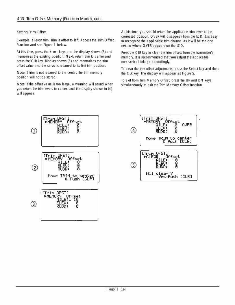
GLID 124
Setting Trim Offset
Example: aileron trim. Trim is offset to left. Access the Trim OffsetFunction and see Figure 1 below.
At this time, press the + or - keys and the display shows (2) andmemorizes the existing position. Next, return trim to center andpress the CLR key. Display shows (3) and memorizes the trimoffset value and the servo is returned to its first trim position.
Note: If trim is not returned to the center, the trim memoryposition will not be stored.
Note: If the offset value is too large, a warning will sound whenyou return the trim levers to center, and the display shown in (4)will appear.
At this time, you should return the applicable trim lever to thecorrected position. OVER will disappear from the LCD. It is easyto recognize the applicable trim channel as it will be the onenext to where OVER appears on the LCD.
Press the CLR key to clear the trim offsets from the transmitter’smemory. It is recommended that you adjust the applicablemechanical linkage accordingly.
To clear the trim offset adjustments, press the Select key and thenthe CLR key. The display will appear as Figure 5.
To exit from Trim Memory Offset, press the UP and DN keyssimultaneously to exit the Trim Memory Offset function.
4.13 Trim Offset Memory (Function Mode), cont.
1
2
3
4
5

GLID 125
The XP8103 offers six (6) programmable mixes to be used for anumber of different purposes. The functions allows mixing anyone channel to any other channel.
The mix can remain ON at all times, or be switched OFF inflight using a number of different switches. Refer to Figure 4.13Band 4.13C. Each channel is identified by a four character name(i.e., Aileron - AILE, Elevator - ELEV, etc.). The channel appearingfirst is known as the “master channel,” or the channel to whichyou want to mix. The second channel is known as the “slavechannel,” or the channel that is being mixed into the masterchannel. For example, AILE - RUDD would indicate aileron torudder mixing — each time the aileron stick is moved, theaileron will deflect, and the rudder will automatically move in thedirection and to the value input. Mixing is proportional, sosmall inputs of the master channel will produce small outputs ofthe slave channel. Each programmable mix has a mixing“offset.” The purpose of the mixing offset is to redefine theneutral position of the slave channel.
Multi-Point Programmable Mixing
Programmable mixes 1 and 2 have the capability for multi-pointprogrammable mixing. The graphic mixing curve, located on the
right side of your screen, indicates the mixing curve selectedand is a useful reference tool when adjusting or storing points.Up to 5 points can be stored, and these points can be movedindependently to any desired servo position from 0 to 100%.(Refer to figure 4.1C).
Press the DN and Select keyssimultaneously to access theFunction Mode List Display
4.14 Programmable Mixing (1-6) (Function Mode)
Press the UP and DN keyssimultaneously to enter/exitthe Function Mode
Press the reset value atcursor to factory presetpostion/value or toinhibit Mixing function
DN SELECT CH CH CLEARUP
To ProgrammableMixing #2
To Flap POTAdjustment function
Press either the + or - key toactivate the mixing function; toincrease/decrease values; andto change the EXP functionfrom OFF to ON
Press to movethe cursor
→ Mixing Channel
↓Point
↓Switch
(4.13B)
(4.13C)
Accessing the Programable Mixing Functions
Place the transmitter power switch in the ON position. Press theMode UP and DN keys simultaneously to enter the Function
Mode. Press either the UP or DN keys until PROG. Mix 1appears in the upper left portion of the LCD (refer to figurebelow).
MIX Mixing Switches available in each programmable mix
1 On → MIX → FLP-D → FLP-G
2 On → MIX → BTFYO → BTFY1
3 On → MIX → BTFYO → BTFY 1
4 On → MIX → FLP-D → FLP-U
5 On → MIX → FLP-D → FLP-U
6 On → MIX → BTFYO → BTFY1
Key Display Switch display Switch lever position for mixing on
ON Mixing is always ON
MIX Mixing switch is forward, ON
FLP-D Flap switch is down position ON
FLP-U Flap switch is up position ON
BTFY0 Butterfly mixing switch is 0 position ON
BTFY1 Butterfly mixing switch is 1 position ON

GLID 126
Note about Mixings 1 and 3:
1. When the slave channel is aileron, its mixing operation iseffected with preset differential.
2. When the slave channel is flap, its mixing operation iseffected to preset flap to aileron mixing (2 steps mixing).
Note about Mixing 2 and 4:
When the master channel is spoiler, its operation is included inspoiler trim operations.
Note about Mixings 5 and 6:
1. When the master channel is aileron, elevator or rudder, thetrims are functional for the Master and Slave channels.
2. Mixes 5 and 6 incorporate include mixing.
Press the UP and DN keyssimultaneously to enter/exitthe Function Mode
Master channel
Present stickposition
Point to be adjusted
Mixing value (maximum ±100)
Mixing switchMixing value atpresent stickposition
Slave channel
Channel indicatorSPOI: SpoilerAILE: AileronELEV: ElevatorRUDD: RudderPOT 5: Right AileronPOT 6: FlapAUX2: Right FlapAUX3: Extra Channel (AUX3)
Press the DN and Select keyssimultaneously to access theFunction Mode List Display
Press to reset value atcursor to factory presetposition/value, or toinhibit mixing
DN SELECT CH CH CLEARUP
To ProgrammableMixing (2-6)
To Trim Offsetfunction
Press to selectchannels to bemixed, and tomove cursor ongraph to points tobe adjusted
Press either the +or - key to activatethe mixingfunction, toincrease/decreasevalues, and tochange the EXPfunction from OFFto ON
Press to movethe cursor atleft of screen
4.14 Programmable Mixing (1-6), cont.
Assigning Channels
Using the SEL key, move the cursor to the left of the masterchannel. Press the left or right CH keys to position the cursorbelow the master or slave channel. Press the + or - keys to selectthe desired channels.
Operating with a Switch
Pressing the SEL key, position the cursor to the side of SW: andusing the + or - keys select the desired switch for the particularprogram mix being used. Refer to figure 4.13B.
Assigning Mixing Values
Position the cursor to the left of “Point” and press the left or rightCH keys to reverse the position point. Increase or decrease themixing value using the + or - keys or the CLR key. When youwish to reverse the mixing direction, press the - key to increasethe minus value to the desired position. To activate point 1 or 3with “INH” displayed, press the + or - key at that position todisplay mixing value. Press the CLR key if you want to inhibitmixing. Mixing value “0” can be set at points L, 2, and H bypressing the CLR key.
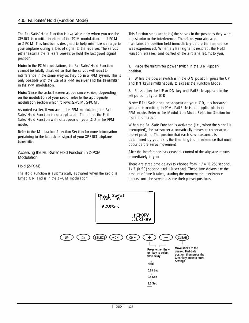
GLID 127
4.15 Fail-Safe/Hold (Function Mode)
The Fail-Safe/Hold Function is available only when you use theXP8103 transmitter in either of the PCM modulations — S-PCMor Z-PCM. This function is designed to help minimize damage toyour airplane during a loss of signal to the receiver. The servoseither assume the fail-safe presets or hold the last good signalposition.
Note: In the PCM modulations, the Fail-Safe/Hold Functioncannot be totally disabled so that the servos will react tointerference in the same way as they do in a PPM system. This isonly possible with the use of a PPM receiver and the transmitterin the PPM modulation.
Note: Since the actual screen appearance varies, dependingon the modulation of your radio, refer to the appropriatemodulation section which follows (Z-PCM, S-PCM).
As noted earlier, if you are in the PPM modulation, the Fail-Safe/Hold Function is not applicable. Therefore, the Fail-Safe/Hold Function will not appear on your LCD in the PPMmode.
Refer to the Modulation Selection Section for more informationpertaining to the broadcast signal of your XP-8103 airplanetransmitter.
Accessing the Fail-Safe/Hold Function in Z-PCMModulation
Hold (Z-PCM)
The Hold Function is automatically activated when the radio isturned ON and is in the Z-PCM modulation.
This function stops (or holds) the servos in the positions they werein just prior to the interference. Therefore, your airplanemaintains the position held immediately before the interferencewas experienced. When a clear signal is restored, the HoldFunction releases, and control of the airplane returns to you.
1. Place the transmitter power switch in the ON (upper)position.
2. While the power switch is in the ON position, press the UPand DN keys simultaneously to access the Function Mode.
3. Press either the UP or DN key until Fail-Safe appears in theleft portion of your LCD.
Note: If Fail-Safe does not appear on your LCD, it is becauseyou are transmitting in PPM. Fail-Safe is not applicable in thePPM mode. Refer to the Modulation Mode Selection Section formore information.
When the Fail-Safe Function is activated (i.e., when the signal isinterrupted), the transmitter automatically moves each servo to apreset position. The position that each servo assumes isdetermined by you, as is the time length of interference that mustoccur before servo movement.
After the interference has ceased, control of the airplane returnsimmediately to you.
There are three time delays to choose from: 1/4 (0.25) second,1/2 (0.50) second and 1.0 second. These time delays are theamount of time it takes, starting the moment the interferenceoccurs, until the servos assume their preset positions.
Move sticks to thedesired Fail-Safepostion, then press theClear key once to storesettings
DN SELECT CH CH CLEARUP
Press either the +or - key to selecttime delay
↓Hold
↓0.25 Sec
↓0.5 Sec
↓1.0 Sec

GLID 128
Setting Fail-Safe/Hold Memory in Z-PCM Modulation
1. After accessing the Fail-Safe Function, it is time to adjust theFail-Safe presets.
2. Select among the three time delays (1/4, 1/2 or 1.0seconds). To do so, simply press the + or - key until theappropriate delay appears on the screen.
3. Hold the transmitter sticks in the position that you want theservos to assume during signal loss conditions. You candetermine fail-safe preset positions for the other channels byplacing the potentiometers and switches in the positions that youwant them to assume during interference.
4. With the sticks, switches and potentiometers in the fail-safepositions, touch the CLR key. This will enter these locations as thefail-safe memory settings. A high pitched beep will indicate thatthis setting has been stored.
5. To confirm that the input of data was successful, switch thetransmitter OFF. The controls will move to the input locations. Ifnot, repeat step 4 again.
6. To exit the Fail-Safe Function, press the UP and DN keyssimultaneously.
Note: These preset positions remain stored in the transmitter’smemory until both the transmitter battery pack and the lithiumback-up battery have been removed (or until data reset has beenperformed). Therefore, you do not have to reset the fail-safeeach time you fly. Should you want to re-adjust the fail-safepresets, access the Fail-Safe Function and adjust the presets asyou have just done. The transmitter automatically recalls thesettings for the last fail-safe adjustment.
Accessing the Fail-Safe/Hold Memory in S-PCM Modulation
Hold (S-PCM)
The Hold Function is automatically activated when the radio isturned ON and in the S-PCM modulation.
This function stops (or holds) the servos in the positions they werein just prior to the interference. Therefore, your airplanemaintains the position held immediately before the interferencewas experienced. When a clear signal is restored, the HoldFunction releases, and control of the airplane returns to you.
1. Place the transmitter power switch in the ON (upper)position.
2. While the power switch is in the ON position, press the UPand DN keys simultaneously to access the Function Mode.
3. Press either the UP or DN key until Fail-Safe appears in theleft portion of your LCD.
Note: If Fail-Safe does not appear on your LCD, it is becauseyou are transmitting in PPM. Fail-Safe is not applicable in thePPM mode. Refer to the Modulation Mode Selection Section formore information.
Fail Safe/Hold Combination in S-PCM Modulation
The XP8103 allows you to combine the hold and fail-safe presetsfor all eight (8) channels on the receiver — you can select fail-safe or hold independently for all channels on your aircraft. Inother words, some channels will hold their last clear signalposition, while others assume the preset position. Once the fail-safe has been activated by signal interruption (interference), thetransmitter automatically moves the servos to a preset position.The predetermined servo positions are set by you. In the S-PCMfail-safe, the time delay (the amount of time it takes, starting themoment the interference occurs, until the servos assume thepreset positions) is fixed at .25, or 1/4, second.
After the interference has ceased, normal operation of theairplane returns to you immediately.
Setting the Fail-Safe/Hold Memory in S-PCM Modulation
1. After accessing the Fail-Safe Function, it is time to adjust thefail-safe presets.
2. Select all of the channels for which you want to enter a fail-safe preset. This is done by pressing the left or right CH keyand moving the cursor arrow over the desired channel. Pressingthe + or - key will cause the particular channel to assume a“hold” or “preset” fail-safe condition which is determined bypositioning the particular control and pressing the CLR key. Thetransmitter will memorize the switch fail-safe position andautomatically transfer the setting to the receiver.
3. Confirmation of proper fail-safe presets/holds is made byturning the transmitter OFF and observing the aircraft’s controlfunctions.
4.15 Fail-Safe/Hold (Function Mode), cont.

GLID 129
4.15 Fail-Safe/Hold (Function Mode), cont.
Press the UP and DN keyssimultaneously to enter/exitthe Function Mode
Press the DN and Select keyssimultaneously to access theFunction Mode List Display
Move sticks to desiredFail- Safe position, thenpress the Clear key onceto store settings
DN SELECT CH CH CLEARUP
To Trainer Function
To ProgrammableMixing 6
Press either key tomove arrow todesired channel
Press either the +or - key to selecteither Hold or Fail -Safe positions foreach channel
When switch is inupper position,Fail-Safe isactivated
When switch is inlower position, Hold(last command) isactivated Value represents the
stored position offail-safe mode of thechannel indicated bythe cursor
Channels being programmedSPOI: SpoilerAIL1: AileronELEV: ElevatorRUDD: RudderAIL2: Right AileronFLAP: Left FlapAUX2: Right FlapAUX3: Extra Channel (AUX3)

GLID 130
4.16 Trainer (Function Mode)
The XP8103 transmitter employs two separate types of trainersystems:
A. Normal trainer system — all functions are controlled byeither the master transmitter or the slave transmitter.
B. Programmable function trainer — stick functions may beassigned to the slave one at a time. Since the control functionscan be transferred one at a time, students can concentrate ononly one function at a time until they are competent to fly solo.
Basic Connections and Limitations
1. The slave transmitter must be PPM (Pulse Position Modulation)with a DSC (direct servo control) jack. If the slave transmitter isPPM/PCM selectable, select PPM. The master transmitter can beS-PCM, Z-PCM or PPM.
2. Plug the trainer cord into each transmitter’s DSC jack. Noteeach transmitter will appear to be ON, but neither is actuallytransmitting at this time.
3. Switch the master transmitter ON. Do not switch on theslave transmitter; you must only have the master transmitterON.
4. Pull the trainer switch on the master transmitter toward you totransfer control to the slave. Releasing the switch automaticallyreverts control to the master transmitter.
5. Be sure the slave transmitter servo reversing, dual rates, andpoint adjustment and trims are identical to the master transmitter.This can be checked by pulling the trainer switch toward you. Ifthe control surfaces move, adjust the slave transmitter until thetrainer switch can be activated without a change of the controlsurface position.
A. Using the Normal Trainer System
In this mode, all functions are switched from the master to theslave using the trainer switch. This is the normal mode. Nofunction set-up (reversing switch or travel adjust) is necessary toactivate this system.
Normal trainer display
Press the UP and DN keyssimultaneously to enter/exitthe Function Mode
Press the DN and Select keyssimultaneously to access theFunction Mode List Display
Press to reset tofactory presetposition (All Master)
DN SELECT CH CH CLEARUP
To Timer Function
To Fail-Safe (PCM Only) or programmable mixingfunction
Press either keyto move arrow todesired channel
Press either the + or -key to select channelsto be activated(Master-Slave) When all channels areset for Master,condition is set toNormal Trainer
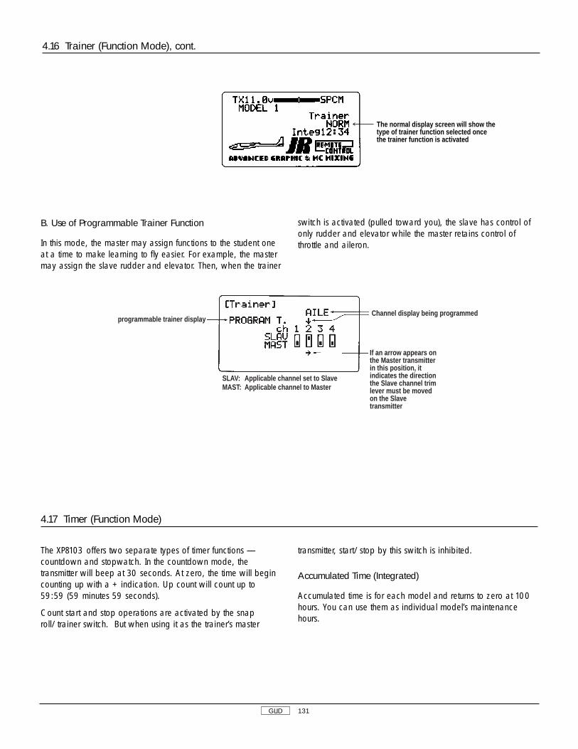
GLID 131
B. Use of Programmable Trainer Function
In this mode, the master may assign functions to the student oneat a time to make learning to fly easier. For example, the mastermay assign the slave rudder and elevator. Then, when the trainer
switch is activated (pulled toward you), the slave has control ofonly rudder and elevator while the master retains control ofthrottle and aileron.
programmable trainer displayChannel display being programmed
If an arrow appears onthe Master transmitterin this position, itindicates the directionthe Slave channel trimlever must be movedon the Slavetransmitter
SLAV: Applicable channel set to SlaveMAST: Applicable channel to Master
4.16 Trainer (Function Mode), cont.
The XP8103 offers two separate types of timer functions —countdown and stopwatch. In the countdown mode, thetransmitter will beep at 30 seconds. At zero, the time will begincounting up with a + indication. Up count will count up to59:59 (59 minutes 59 seconds).
Count start and stop operations are activated by the snaproll/trainer switch. But when using it as the trainer’s master
transmitter, start/stop by this switch is inhibited.
Accumulated Time (Integrated)
Accumulated time is for each model and returns to zero at 100hours. You can use them as individual model’s maintenancehours.
4.17 Timer (Function Mode)
The normal display screen will show thetype of trainer function selected oncethe trainer function is activated

GLID 132
Accumulated timeminuteshours
Countdown timer settingtime (0.00 to 59.50)
Inhibit
Countdown Timer
Stopwatch
Press to reset timerto zero
NORMAL DISPLAY w/countdown timer function selected
Timer setting time
DN SELECT CH CH CLEARUP
Press either keyto start/stop timer
Press the UP and DN keyssimultaneously to enter/exitthe Function Mode
Press the DN and Select keyssimultaneously to access theFunction Mode List Display
Press to selectTimer Setting:
↓INH
↓Countdown Timer
↓Stopwatch
DN SELECT CH CH CLEARUP
To Servo OutputIndicator
To Trainerfunction
Press either keyto move arrow
Press to inhibitTimer function orto set Integ-Tvalue to 0
or to increase or decreasecountdown timer settings
Press to movecursor from timerto Integ-T
4.17 Timer (Function Mode), cont.

GLID 133
This function displays each servo’s operating value. Each barcenter indicates neutral position. Left or right dots indicate 50%,100% and 150%.
Note: All indications are actual positions including adjustmentsand mixing. It is also possible to view servo travel/servodirections when mixing functions are activated.
4.18 Servo Output Indicator (Function Mode)
Press the UP and DN keyssimultaneously to enter/exitthe Function Mode
Press the DN and Select keyssimultaneously to access theFunction Mode List Display
50%100%150%
ATV Travel
DN SELECT CH CH CLEARUPTo Dual RateExponential function
To Timerfunction
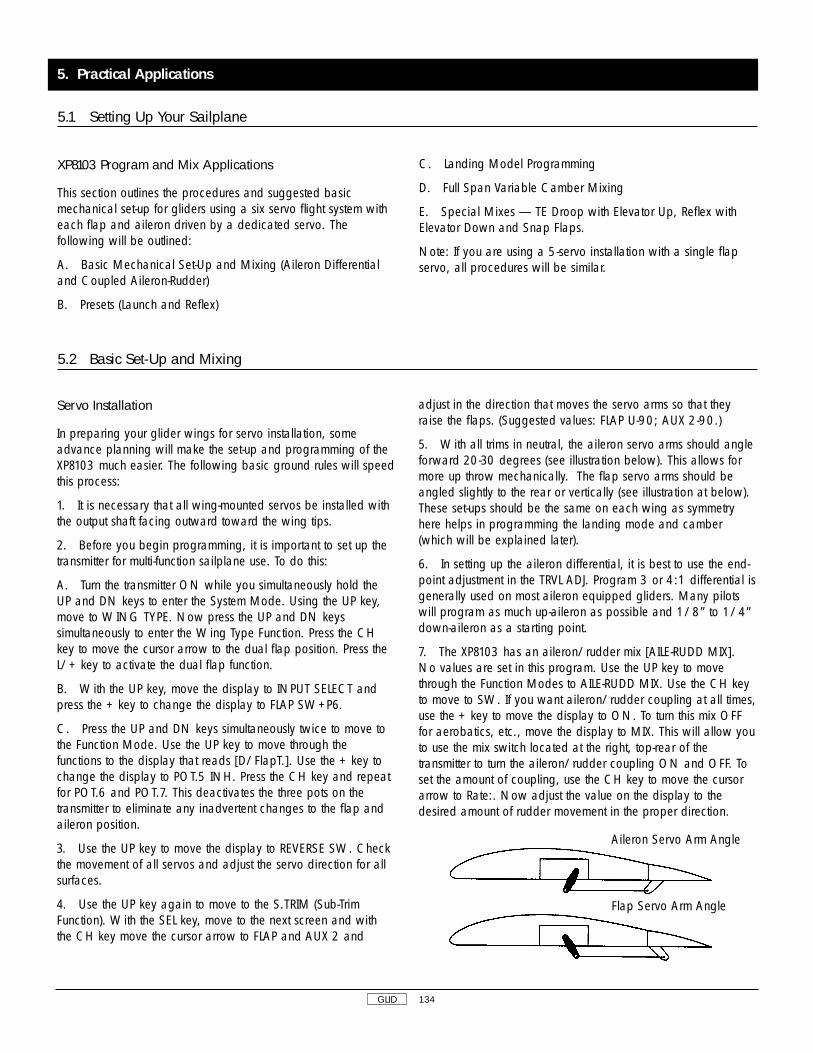
Servo Installation
In preparing your glider wings for servo installation, someadvance planning will make the set-up and programming of theXP8103 much easier. The following basic ground rules will speedthis process:
1. It is necessary that all wing-mounted servos be installed withthe output shaft facing outward toward the wing tips.
2. Before you begin programming, it is important to set up thetransmitter for multi-function sailplane use. To do this:
A. Turn the transmitter ON while you simultaneously hold theUP and DN keys to enter the System Mode. Using the UP key,move to WING TYPE. Now press the UP and DN keyssimultaneously to enter the Wing Type Function. Press the CHkey to move the cursor arrow to the dual flap position. Press theL/+ key to activate the dual flap function.
B. With the UP key, move the display to INPUT SELECT andpress the + key to change the display to FLAP SW+P6.
C. Press the UP and DN keys simultaneously twice to move tothe Function Mode. Use the UP key to move through thefunctions to the display that reads [D/FlapT.]. Use the + key tochange the display to POT.5 INH. Press the CH key and repeatfor POT.6 and POT.7. This deactivates the three pots on thetransmitter to eliminate any inadvertent changes to the flap andaileron position.
3. Use the UP key to move the display to REVERSE SW. Checkthe movement of all servos and adjust the servo direction for allsurfaces.
4. Use the UP key again to move to the S.TRIM (Sub-TrimFunction). With the SEL key, move to the next screen and withthe CH key move the cursor arrow to FLAP and AUX 2 and
adjust in the direction that moves the servo arms so that theyraise the flaps. (Suggested values: FLAP U-90; AUX 2-90.)
5. With all trims in neutral, the aileron servo arms should angleforward 20-30 degrees (see illustration below). This allows formore up throw mechanically. The flap servo arms should beangled slightly to the rear or vertically (see illustration at below).These set-ups should be the same on each wing as symmetryhere helps in programming the landing mode and camber(which will be explained later).
6. In setting up the aileron differential, it is best to use the end-point adjustment in the TRVL ADJ. Program 3 or 4:1 differential isgenerally used on most aileron equipped gliders. Many pilotswill program as much up-aileron as possible and 1/8” to 1/4”down-aileron as a starting point.
7. The XP8103 has an aileron/rudder mix [AILE-RUDD MIX].No values are set in this program. Use the UP key to movethrough the Function Modes to AILE-RUDD MIX. Use the CH keyto move to SW. If you want aileron/rudder coupling at all times,use the + key to move the display to ON. To turn this mix OFFfor aerobatics, etc., move the display to MIX. This will allow youto use the mix switch located at the right, top-rear of thetransmitter to turn the aileron/rudder coupling ON and OFF. Toset the amount of coupling, use the CH key to move the cursorarrow to Rate:. Now adjust the value on the display to thedesired amount of rudder movement in the proper direction.
GLID 134
XP8103 Program and Mix Applications
This section outlines the procedures and suggested basicmechanical set-up for gliders using a six servo flight system witheach flap and aileron driven by a dedicated servo. Thefollowing will be outlined:
A. Basic Mechanical Set-Up and Mixing (Aileron Differentialand Coupled Aileron-Rudder)
B. Presets (Launch and Reflex)
C. Landing Model Programming
D. Full Span Variable Camber Mixing
E. Special Mixes — TE Droop with Elevator Up, Reflex withElevator Down and Snap Flaps.
Note: If you are using a 5-servo installation with a single flapservo, all procedures will be similar.
5.1 Setting Up Your Sailplane
5.2 Basic Set-Up and Mixing
Aileron Servo Arm Angle
Flap Servo Arm Angle
5. Practical Applications
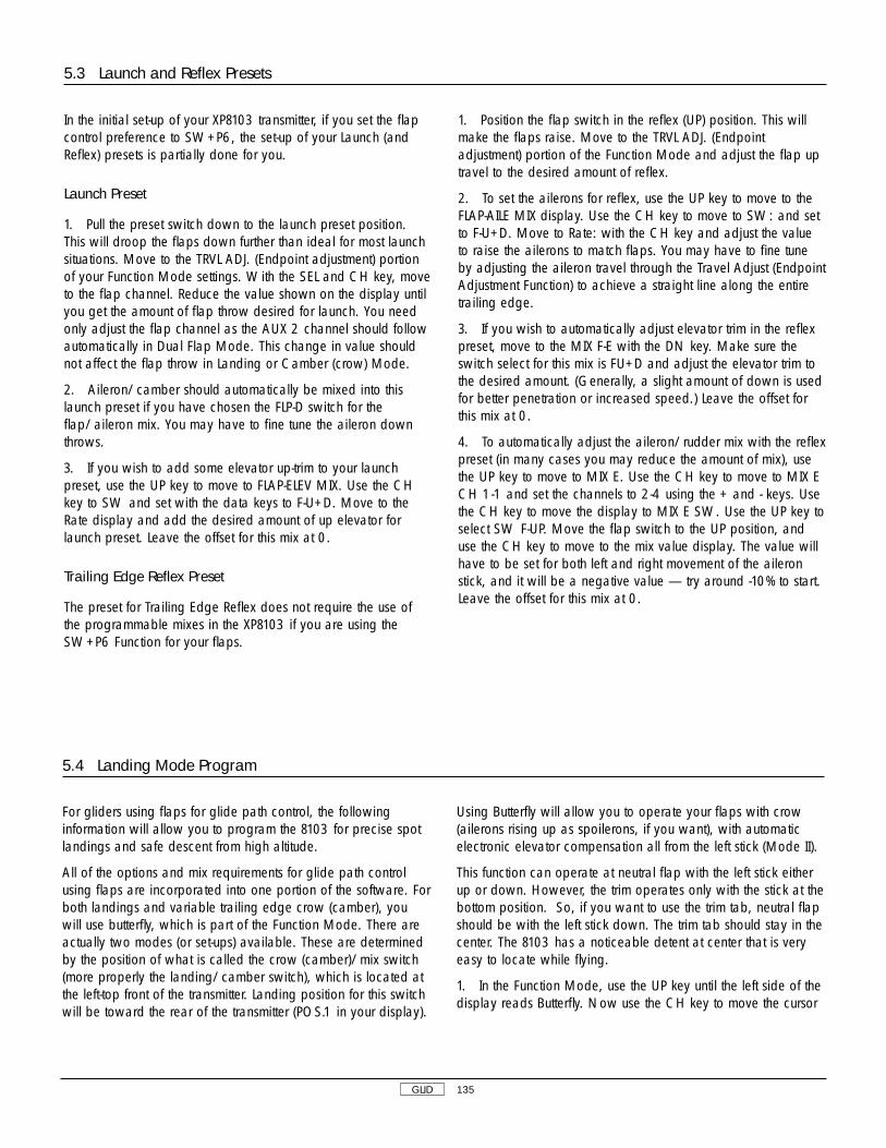
GLID 135
In the initial set-up of your XP8103 transmitter, if you set the flapcontrol preference to SW+P6, the set-up of your Launch (andReflex) presets is partially done for you.
Launch Preset
1. Pull the preset switch down to the launch preset position.This will droop the flaps down further than ideal for most launchsituations. Move to the TRVL ADJ. (Endpoint adjustment) portionof your Function Mode settings. With the SEL and CH key, moveto the flap channel. Reduce the value shown on the display untilyou get the amount of flap throw desired for launch. You needonly adjust the flap channel as the AUX 2 channel should followautomatically in Dual Flap Mode. This change in value shouldnot affect the flap throw in Landing or Camber (crow) Mode.
2. Aileron/camber should automatically be mixed into thislaunch preset if you have chosen the FLP-D switch for theflap/aileron mix. You may have to fine tune the aileron downthrows.
3. If you wish to add some elevator up-trim to your launchpreset, use the UP key to move to FLAP-ELEV MIX. Use the CHkey to SW and set with the data keys to F-U+D. Move to theRate display and add the desired amount of up elevator forlaunch preset. Leave the offset for this mix at 0.
Trailing Edge Reflex Preset
The preset for Trailing Edge Reflex does not require the use ofthe programmable mixes in the XP8103 if you are using theSW+P6 Function for your flaps.
1. Position the flap switch in the reflex (UP) position. This willmake the flaps raise. Move to the TRVL ADJ. (Endpointadjustment) portion of the Function Mode and adjust the flap uptravel to the desired amount of reflex.
2. To set the ailerons for reflex, use the UP key to move to theFLAP-AILE MIX display. Use the CH key to move to SW: and setto F-U+D. Move to Rate: with the CH key and adjust the valueto raise the ailerons to match flaps. You may have to fine tuneby adjusting the aileron travel through the Travel Adjust (EndpointAdjustment Function) to achieve a straight line along the entiretrailing edge.
3. If you wish to automatically adjust elevator trim in the reflexpreset, move to the MIX F-E with the DN key. Make sure theswitch select for this mix is FU+D and adjust the elevator trim tothe desired amount. (Generally, a slight amount of down is usedfor better penetration or increased speed.) Leave the offset forthis mix at 0.
4. To automatically adjust the aileron/rudder mix with the reflexpreset (in many cases you may reduce the amount of mix), usethe UP key to move to MIX E. Use the CH key to move to MIX ECH 1-1 and set the channels to 2-4 using the + and - keys. Usethe CH key to move the display to MIX E SW. Use the UP key toselect SW F-UP. Move the flap switch to the UP position, anduse the CH key to move to the mix value display. The value willhave to be set for both left and right movement of the aileronstick, and it will be a negative value — try around -10% to start.Leave the offset for this mix at 0.
5.3 Launch and Reflex Presets
5.4 Landing Mode Program
For gliders using flaps for glide path control, the followinginformation will allow you to program the 8103 for precise spotlandings and safe descent from high altitude.
All of the options and mix requirements for glide path controlusing flaps are incorporated into one portion of the software. Forboth landings and variable trailing edge crow (camber), youwill use butterfly, which is part of the Function Mode. There areactually two modes (or set-ups) available. These are determinedby the position of what is called the crow (camber)/mix switch(more properly the landing/camber switch), which is located atthe left-top front of the transmitter. Landing position for this switchwill be toward the rear of the transmitter (POS.1 in your display).
Using Butterfly will allow you to operate your flaps with crow(ailerons rising up as spoilerons, if you want), with automaticelectronic elevator compensation all from the left stick (Mode II).
This function can operate at neutral flap with the left stick eitherup or down. However, the trim operates only with the stick at thebottom position. So, if you want to use the trim tab, neutral flapshould be with the left stick down. The trim tab should stay in thecenter. The 8103 has a noticeable detent at center that is veryeasy to locate while flying.
1. In the Function Mode, use the UP key until the left side of thedisplay reads Butterfly. Now use the CH key to move the cursor

GLID 136
arrow to SPOI OFFSET. With the trim tab centered and the leftstick in position for neutral flap (low stick), press the CLR key tothe right of the data keys. This stores your offset or neutral point.
2. Use the CH key and go to SPOI-FLAP. Using the + or - keys,program the mix value to give 90 degrees of flap throw. It maybe necessary to return to TRVL ADJ. (endpoint adjustment) to finetune the flap throws and keep both surfaces even as they arelowered.
3. Use the CH key to move to SPOI-ELEV where you can nowset your elevator compensation. The value may vary dependingon the size and type of elevator used. A starting point for allflying stabilizers will be approximately 35% down; a fixed
stabilizer with elevator will generally use a smaller percentage.
4. If you want to add crow (spoilerons), use the CH key tomove to SPOI-AILE. With the data keys, set the mix value for thedesired amount of up aileron (crow). This is an option that not allpilots will use, but it can be a very effective tool in helping toslow down for landing. Depending on the design of glider youare flying, anywhere from 5-45 degrees of crow (camber) canbe useful.
This basic set-up will provide you with an effective landing modefor almost all conditions. The given values are only guidelines,and you will need to experiment and adjust them to yourindividual need and style.
The Full Span/Variable Crow/Camber Function also uses theButterfly portion of the Function Mode. The purpose of thisfunction is to allow you to vary the crow (camber) or position ofthe trailing edge of your wings’ airfoil while flying, combinedwith the ability to adjust to variable flying conditions. To use thisfunction, place the landing/crow (camber) switch in POS.0,which is toward the face of the transmitter.
1. Use the Ch key to move the cursor to SPOI-FLAP. With theleft stick moved to the full throw (down flap) position, adjust themix value for approximately 1/4” to 3/8” down flap.
2. Leave the left stick in that position and use the CH key tomove to SPOI-AILE. Use the data keys to move the aileronsdown the same amount as the flaps. You may have to fine tune
each aileron in the Endpoint Adjustment Function (TRVL ADJ.) toget a straight line along the trailing edge.
3. If you want to change elevator trim as you add crow(camber), you can assign a value in SPOI-ELEV for this purpose.
4. If you have set the camber and the landing modes at neutralwith the left stick in lower position where the trim tab willfunction, the trailing edge will reflex (move up) 2-3 degrees (incamber mode only) when the trim tab is moved down. For mostmodern glider airfoils, this is adequate for increased speed orpenetration in wind.
5.5 Full Span/Variable Crow/Camber
5.4 Landing Mode Program, cont.

GLID 137
The open programmable mixes available in the XP8103 allowyou to enhance your presets with a variety of mix applications.Another programming feature included in the XP8103 is theability to assign a switch to use for the following mixes: Allprogrammable mixes, Elevator-Flaperons, Aileron-Flaperons,Flaperons-Elevator, and Flaperons-Aileron. In addition, the lattertwo mixes also include a trim offset for the flap.
Flaperons
Following are guidelines for mixing flaps to follow aileronmovement. This mix will work as part of the Launch and/orreflex preset at your option. The 8103 transmitter must have thedual flaps activated in the Function Mode to access theaileron/flap mix.
1. In the Function Mode, use the UP key to move to the MIXAILE-FLAP mix. Now with the CH key, move to the switch selectto select your switch option.
2. Move to Rate with the CH key and enter the value for throw.There is no separate mix value for each direction. There is nooffset used with this mix.
Elevator Flap/Mix
The Elevator/Flap Mix is another optional mix that can be usedwith either preset or other switch options. Different mix valuesare programmed for up and down elevator throw. This mix isgenerally used with slope aerobatics, or for multi-task speed anddistance tasks.
1. From the aileron/flap mix, use the DN key to move to ELEV-FLAP mix. Now push the CH key to move to switch select. In
many multi-task applications, this mix will be used with reflexFLP-U.
2. Move back to Rate and enter for desired direction andthrow. Most common is to drop the wing tailing edge with upElevator.
Options and Program Ideas
With some time to experiment and learn the transmitter, you willdiscover a number of other ways to apply the above functions. Ifyou fly with the aileron/rudder mix always ON, the mix switchcan be used as another switch option. The availableprogrammable mixes also allow for a variety of scale andspecial-use functions.
Snap Flaps
Snap Flaps is a function that mixes a given amount of downflaps when a specified up elevator is given. This aids in tightturns and can be handy when circling in tight thermals or forchanging direction quickly.
Select PROG.MIX 1 and mix ELEV-FLAP by pressing the + and -keys. Press the SEL key until the cursor arrow points to the Point L.Press the CLR key to clear out the mix value. Press the CH keyuntil point H is displayed. Press the CLR key to zero out the Hposition. Press the CH key until Point 1 is displayed. Press the +key to achieve zero value in Point 1. Press the CH key until PointL is displayed. Then press the + or - key to achieve the desiredamount of elevator to flap mixing with full up elevator.
Choose the switch position you want to turn off/on this mix.Many pilots choose to leave this function on at all times.
5.6 Special Mixing

GLID 138
XP8103 DATA SHEET GLID
SPCM • ZPCM • PPM
FAIL-SAFE (SPCM • ZPCM)
DIFFERENTIAL

EXCLUSIVELY DISTRIBUTED BY HORIZON HOBBY DISTRIBUTORS, INC.

XP8103 Manual AddendumPlease refer to the info below for clarification before using these functions.
This information is applicable in all model types (Airplane, Helicopter, Glider).
The XP8103 offers two separate types of timer functions —countdown and stopwatch. In the countdown mode, the trans-mitter will beep at 30 seconds. At zero, the time will begincounting up with a + indication. Up count will count up to59:59 (59 minutes 59 seconds).
Count start and stop operations are activated by the snaproll/trainer switch. But when using it as the trainer’s master
transmitter, start/stop by this switch is inhibited.
Accumulated Time (Integrated)
Accumulated time is for each model and returns to zero at 100hours. You can use them as individual model’s maintenancehours.
Timer (Function Mode)
Accumulated timeminuteshours
Countdown timer settingtime (0.00 to 59.50)
Inhibit
Countdown Timer
Stopwatch
Timer setting time
NORMAL DISPLAY w/countdown timer function selected
Press to transfer the correct timerdata for the current model selected,or to reset timer to zero
DN SELECT CH CH CLEARUP
Press either keyto start/stop timer
Press the UP and DN keyssimultaneously to enter/exitthe Function Mode
Press the DN and Select keys simul-taneously to access the FunctionMode List Display
Press to selectTimer Setting:
↓INH
↓Countdown Timer
↓Stopwatch
DN SELECT CH CH CLEARUP
To Servo OutputIndicator
To Trainerfunction
Press either keyto move arrow
Press to inhibitTimer function orto set Integ-Tvalue to 0
or to increase or decreasecountdown timer settings
Press to movecursor from timerto Integ-T
When using the model select function (System Mode) tochange from models 1-10, it is necessary to push the clearkey once after the system has been returned to the normaldisplay to also transfer the timer data. If the clear key is notpressed, the time set for the current model will change tothat of the time set for the previously used model.
Important Note:
Airplane 54 Helicopter 95 Glider 131Manual Page

Model Select (System Set-Up Mode)
The XP8103 transmitter employs a memory function which mem-orizes data for up to 10 individual aircraft. All settings alongwith type selection, function, and different aircraft are used byone transmitter. For example, Model 1 is airplane and Model 2is helicopter. To avoid confusing models, inputting model names
for each aircraft is recommended (see page 29). Press the UPand DN keys simultaneously and turn the power switch ON toaccess the System Set-Up Mode.
The display below shows the model selection function.
model name(if dot is shown, modelname is blank)
modulation
type
model number (1-10)
DN SELECT CH CH CLEARUP
Press UP and DN keyssimultaneously to exit theSystem Set-Up Mode
To Model Name function
To Info Display function
Function select (select model/copy) Model selection
(1-10)
Press UP and Select keyssimultaneously to access theSystem Mode info display
XP8103 Manual AddendumPlease refer to the info below for clarification before using these functions.
This information is applicable in all model types (Airplane, Helicopter, Glider).
Airplane 28 Helicopter 66 Glider 106Manual Page
It is necessary to press the clear key once after the systemhas been returned to the normal display to also transfer thetimer data. If the clear key is not pressed after the modelselect function, the time setting from the current model willbe changed to the time setting of the previous model.
Timer Data Transfer:


![[8103 - 26546][6467-18575]responsabilidade_fiscal_6467](https://img.dokumen.tips/doc/110x75/55cf8fea550346703ba1341c/8103-265466467-18575responsabilidadefiscal6467.jpg)