Embed Size (px)
Citation preview
Journal of Constructional Steel Research 77 (2012) 180–192
Contents lists available at SciVerse ScienceDirect
Journal of Constructional Steel Research
Introduction of stiffened large rectangular openings in steel plate shear walls
S.A.A. Hosseinzadeh 1, Mohsen Tehranizadeh ⁎Department of Civil Engineering, Amirkabir University of Technology, 424 Hafez Ave, Tehran, 15875‐4413, Iran
⁎ Corresponding author. Tel.: +98 21 6454 3030; faxE-mail addresses: [email protected], ahossei
(SAA. Hosseinzadeh), [email protected] (M. Tehranizad1 Tel.: +98 21 6454 3073; fax: +98 21 6454 3037.
0143-974X/$ – see front matter © 2012 Elsevier Ltd. Aldoi:10.1016/j.jcsr.2012.05.010
a b s t r a c t
a r t i c l e i n f oArticle history:Received 1 February 2012Accepted 17 May 2012Available online 26 June 2012
Keywords:Shear wallsOpeningStiffened openingRectangular openingNonlinear behaviorLocal boundary elements
The nonlinear behavior of steel plate shear walls (SPSWs) with stiffened large rectangular openings used aswindows or doors in buildings is studied. A number of SPSWs with and without openings are numerically an-alyzed, and the results are utilized (a) to characterize the behavior of SPSWs with the openings, (b) to studythe effects of various opening features as well as size of local boundary elements (LBE) around the openingand thickness of infill plates on either side of the opening and (c) to investigate the changes in the systemstrength, stiffness and ductility due to the introduction of the openings. Results show that the procedureaddressed by AISC Design Guide 20 for design of beams above and below the opening level is not perfect.Use of thicker or thinner infill plates or weaker profiles for the LBE can alter the yielding sequence in the sys-tem. Notably, the type, location and geometry of stiffened openings are not influential themselves on the sys-tem strength, although different LBE sizes required for different openings may have some effects. Theintroduction of stiffened openings in different SPSWs increases both the ultimate strength and stiffness,while somewhat decreases the ductility ratio.
© 2012 Elsevier Ltd. All rights reserved.
1. Introduction
Steel plate shear walls (SPSWs) have been increasingly utilized asa lateral force resisting system, which resist both earthquake andwind forces. This structural system has been used in significant build-ings beginning decades ago, and implementation has acceleratedsince the recent years [1]. They provide an effective and economicalsolution for new construction as well as retrofitting of existing struc-tures. A conventional SPSW consists of thin stiffened or unstiffenedsteel plates surrounded by horizontal and vertical boundary elements(HBE and VBE) that can be multiple stories high and one or more bayswide.
Early designs of SPSWs were based on the concept of preventingshear buckling in the infill plate by using either thick infill plate orby adding stiffeners to the infill plate, but in recent years, the ideaof utilizing the post-buckling strength with the use of thin unstiffenedinfill plate has gained wide acceptance from researchers and de-signers globally. Typical SPSW has slender infill plates that are capa-ble of resisting large tension forces by developing diagonal tensionfields in the infill plate, but little or no compression. They should beexpected to buckle under very small lateral loads or even consideredpre-buckled under their own weight prior to loading. It is known thatplastic deformations in SPSWs should primarily be provided by the
: +98 21 6454 [email protected]).
l rights reserved.
infill plates [1,2] and that the boundary members should be designedso as to develop the full tension strength of the infill panels.
Numerous research programs and large-scale experiments havebeen shown that this system possesses high level of initial stiffness,strength, ductility and robustness under cyclic loading [3–12].SPSWs offer significant advantages over many other lateral load‐resisting systems in terms of foundation cost, saving steel, perfor-mance, ease of design, speed and simplicity of construction and us-able space in buildings [1,13]. They can also be accommodated toallow different types of openings within their infill plates.
To date, experimental and analytical research on thin unstiffenedSPSWs is mainly focused on the behavior of SPSWs with solid infillplates (i.e. without openings) and thus, limited research on varioustypes of openings in SPSWs or shear panels has been performed.
Roberts and Sabouri-Ghomi [14] conducted a series of quasi-staticcyclic loading tests on unstiffened steel plate shear panels with cen-trally placed circular openings. Based on the test results, the re-searchers recommended that the strength and stiffness of aperforated panel can be conservatively approximated by applying alinear reduction factor to the strength and stiffness of a similar solidpanel. Deylami and Daftari [15] analyzed more than 50 models witha rectangular opening in the center of the panel using finite elementmethod to investigate the effects of some important geometric pa-rameters, such as plate thickness, the opening height to width ratio,and the areal percentage of the opening. The opening had only twostiffeners with limited length on its vertical edges which were notcontinued across the height of the panel. They concluded that the in-troduction of the opening, even at relatively small percentage, causedan important decrease of shear capacity. In thinner steel plate shear
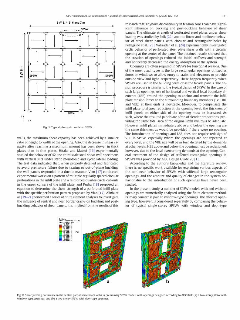
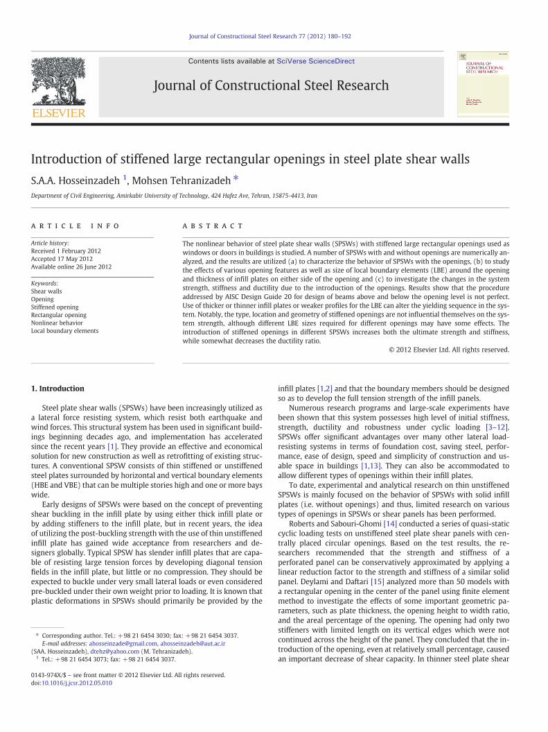
Fig. 1. Typical plan and considered SPSW.
181SAA. Hosseinzadeh, M. Tehranizadeh / Journal of Constructional Steel Research 77 (2012) 180–192
walls, the maximum shear capacity has been achieved by a smallerratio of height to width of the opening. Also, the decrease in shear ca-pacity after reaching a maximum amount has been slower in thickplates than in thin plates. Hitaka and Matsui [16] experimentallystudied the behavior of 42 one-third scale steel shear wall specimenswith vertical slits under static monotonic and cyclic lateral loading.The test data indicated that, when properly detailed and fabricatedto avoid premature failure due to tearing or out-of-plane buckling,the wall panels responded in a ductile manner. Vian [17] conductedexperimental works on a pattern of multiple regularly spaced circularperforations in the infill plate and a reinforced quarter-circle cut-outsin the upper corners of the infill plate, and Purba [18] proposed anequation to determine the shear strength of a perforated infill platewith the specific perforation pattern proposed by Vian [17]. Alinia etal. [19–21] performed a series of finite element analyses to investigatethe influence of central and near border cracks on buckling and post-buckling behavior of shear panels. It is implied from the results of this
a
Fig. 2. Shear yielding occurrence in the central part of some beam webs in preliminary SPSwindow-type openings, and (b) a two-storey SPSW with door-type openings.
research that, anyhow, discontinuity in tension zones can have signif-icant influence on buckling and post-buckling behavior of shearpanels. The ultimate strength of perforated steel plates under shearloading was studied by Paik [22], and the linear and nonlinear behav-ior of steel shear panels with circular and rectangular holes byPellegrino et al. [23]. Valizadeh et al. [24] experimentally investigatedcyclic behavior of perforated steel plate shear walls with a circularopening at the center of the panel. The obtained results showed thatthe creation of openings reduced the initial stiffness and strengthand noticeably decreased the energy absorption of the system.
Openings are often required in SPSWs for functional reasons. Oneof the most usual types is the large rectangular openings utilized asdoors or windows to allow entry to stairs and elevators or provideoutside view and light, respectively. These happen frequently whenSPSWs are used in the building cores or as the facade panels. The de-sign procedure is similar to the typical design of SPSW. In the case ofsuch large openings, use of horizontal and vertical local boundary el-ements (LBE) around the opening to anchor and transmit the infillplate tension forces to the surrounding boundary members (i.e. HBEand VBE) at their ends is inevitable. Moreover, to compensate theinfill plate total area reduction at the opening level, the thickness ofinfill panels on either side of the opening must be increased. Assuch, where the resulted panels are often of slender proportions, pro-viding the same total area of the original infill will thus be adequate.However, infill plates immediately above and below the opening arethe same thickness as would be provided if there were no opening.The introduction of openings and LBE does not require redesign ofVBE in SPSW, especially where the openings are not repeated atevery level, and the VBE size will be in turn dictated by the demandsat other levels. HBE above and below the openingmust be redesigned,however, due to the local overturning demands at the opening. Gen-eral treatment of the design of stiffened rectangular openings inSPSWs was provided by AISC Design Guide 20 [1].
According to the author's knowledge and the literature review,there is no specific work available for explaining various aspects ofthe nonlinear behavior of SPSWs with stiffened large rectangularopenings, and the amount and quality of changes in the system be-havior due to the introduction of such openings have never beenstudied.
In the present study, a number of SPSW models with and withoutopenings are numerically analyzed using the finite element method.Primary concern is paid to window-type openings. The effect of open-ing type, however, is considered separately by comparing the behav-ior of typical single-storey SPSWs with window and door-type
b
W models with openings designed according to AISC 820: (a) a two-storey SPSW with
182 SAA. Hosseinzadeh, M. Tehranizadeh / Journal of Constructional Steel Research 77 (2012) 180–192
openings. Characteristics of the system behavior are discussed bycomparing general behavior of typical SPSWs with and without theopenings as well as by studying infill/frame behaviors of typicalsingle-storey SPSWs with and without the opening. The effects ofopening features are included by varying the geometry and horizon-tal location of the opening in the infill plate of typical single-storeySPSWs. The changes in the system behavior due to the introductionof the openings in terms of ultimate shear strength, ductility and stiff-ness are investigated over a series of SPSWs with different aspect ra-tios and number of stories. The changes in the behavior of the systemdue to the introduction of the openings at arbitrary level(s) of a four-storey SPSW, where it is not demanded to repeat the openings atevery level are also considered.
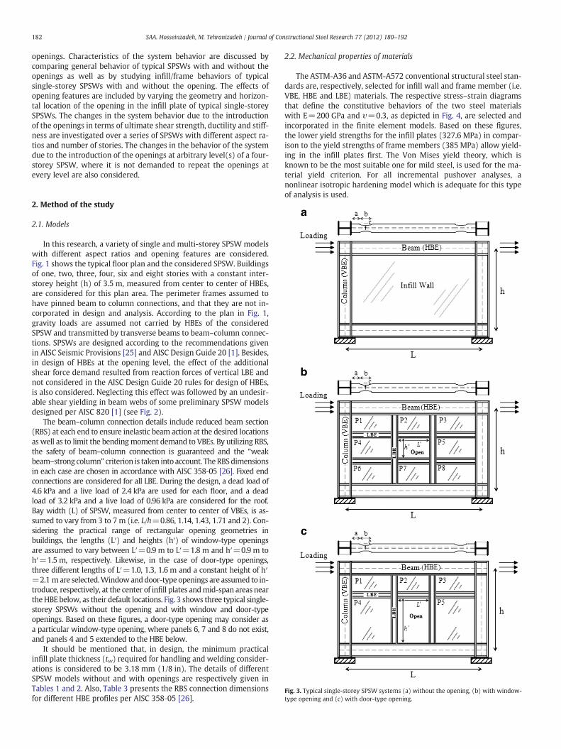
Fig. 3. Typical single-storey SPSW systems (a) without the opening, (b) with window-type opening and (c) with door-type opening.
2. Method of the study
2.1. Models
In this research, a variety of single and multi-storey SPSW modelswith different aspect ratios and opening features are considered.Fig. 1 shows the typical floor plan and the considered SPSW. Buildingsof one, two, three, four, six and eight stories with a constant inter-storey height (h) of 3.5 m, measured from center to center of HBEs,are considered for this plan area. The perimeter frames assumed tohave pinned beam to column connections, and that they are not in-corporated in design and analysis. According to the plan in Fig. 1,gravity loads are assumed not carried by HBEs of the consideredSPSW and transmitted by transverse beams to beam–column connec-tions. SPSWs are designed according to the recommendations givenin AISC Seismic Provisions [25] and AISC Design Guide 20 [1]. Besides,in design of HBEs at the opening level, the effect of the additionalshear force demand resulted from reaction forces of vertical LBE andnot considered in the AISC Design Guide 20 rules for design of HBEs,is also considered. Neglecting this effect was followed by an undesir-able shear yielding in beam webs of some preliminary SPSW modelsdesigned per AISC 820 [1] (see Fig. 2).
The beam–column connection details include reduced beam section(RBS) at each end to ensure inelastic beam action at the desired locationsas well as to limit the bendingmoment demand to VBEs. By utilizing RBS,the safety of beam–column connection is guaranteed and the “weakbeam–strong column” criterion is taken into account. TheRBSdimensionsin each case are chosen in accordance with AISC 358‐05 [26]. Fixed endconnections are considered for all LBE. During the design, a dead load of4.6 kPa and a live load of 2.4 kPa are used for each floor, and a deadload of 3.2 kPa and a live load of 0.96 kPa are considered for the roof.Bay width (L) of SPSW, measured from center to center of VBEs, is as-sumed to vary from 3 to 7 m (i.e. L/h=0.86, 1.14, 1.43, 1.71 and 2). Con-sidering the practical range of rectangular opening geometries inbuildings, the lengths (L′) and heights (h′) of window-type openingsare assumed to vary between L′=0.9 m to L′=1.8 m and h′=0.9 m toh′=1.5 m, respectively. Likewise, in the case of door-type openings,three different lengths of L′=1.0, 1.3, 1.6 m and a constant height of h′=2.1 mare selected.Windowanddoor-type openings are assumed to in-troduce, respectively, at the center of infill plates andmid-span areas neartheHBE below, as their default locations. Fig. 3 shows three typical single-storey SPSWs without the opening and with window and door-typeopenings. Based on these figures, a door-type opening may consider asa particular window-type opening, where panels 6, 7 and 8 do not exist,and panels 4 and 5 extended to the HBE below.
It should be mentioned that, in design, the minimum practicalinfill plate thickness (tw) required for handling and welding consider-ations is considered to be 3.18 mm (1/8 in). The details of differentSPSW models without and with openings are respectively given inTables 1 and 2. Also, Table 3 presents the RBS connection dimensionsfor different HBE profiles per AISC 358‐05 [26].
2.2. Mechanical properties of materials
The ASTM-A36 and ASTM-A572 conventional structural steel stan-dards are, respectively, selected for infill wall and frame member (i.e.VBE, HBE and LBE) materials. The respective stress–strain diagramsthat define the constitutive behaviors of the two steel materialswith E=200 GPa and υ=0.3, as depicted in Fig. 4, are selected andincorporated in the finite element models. Based on these figures,the lower yield strengths for the infill plates (327.6 MPa) in compar-ison to the yield strengths of frame members (385 MPa) allow yield-ing in the infill plates first. The Von Mises yield theory, which isknown to be the most suitable one for mild steel, is used for the ma-terial yield criterion. For all incremental pushover analyses, anonlinear isotropic hardening model which is adequate for this typeof analysis is used.
Table 1Infill plate thicknesses and frame member sizes at different stories of original SPSWs without the openings.
Name # of stories,n
Bay width,L (m)
Aspect ratio,L/h
Plate thickness,tw (mm)
HBE size VBE size
Intermediate Base and top
1S3L 1 3 0.86 1st: 3.18 – W14×176 W14×2831S4L 1 4 1.14 1st: 3.18 – W14×193 W14×3111S5L 1 5 1.43 1st: 3.18 – W14×233 W14×3701S6L 1 6 1.71 1st: 3.18 – W24×250 W14×4551S7L 1 7 2.00 1st: 3.18 – W24×370 W14×5502S5L 2 5 1.43 1st, 2nd: 3.18 W14×132 W14×233 W14×3703S5L 3 5 1.43 1st–3rd: 3.18 W14×132 W14×233 W14×3704S3L 4 3 0.86 1st–4th: 3.18 W14×132 W14×176 W14×2834S4L 4 4 1.14 1st–4th: 3.18 W14×132 W14×193 W14×3114S5L 4 5 1.43 1st–4th: 3.18 W14×132 W14×233 W14×3704S6L 4 6 1.71 1st–4th: 3.18 W14×132 W24×250 W14×4554S7L 4 7 2.00 1st–4th: 3.18 W14×132 W24×370 W14×5506S5L 6 5 1.43 1st–4th: 4.76
5th, 6th: 3.18W14×132 W14×233 1st–4th: W14×500
5th, 6th: W14×3708S5L 8 5 1.43 1st–4th: 6.35
5th, 6th: 4.767th, 8th: 3.18
W14×132 W14×233 1st–4th: W14×7305th–8th: W14×398
183SAA. Hosseinzadeh, M. Tehranizadeh / Journal of Constructional Steel Research 77 (2012) 180–192
2.3. Numerical modeling and method of analysis
The commercially availablefinite element programABAQUS/Standard[27] is utilized for all Eigen-value and incremental nonlinear pushoveranalyses. All frame members and infill plates are finely meshed andmodeled using a general-purpose four-node doubly-curved shell elementwith reduced integration (ABAQUS element S4R). Reduced integration el-ements are used as they give accurate results and significantly reduce
Table 2Infill plate thicknesses and frame member sizes at different stories of SPSWs with the open
Name OriginalSPSWa
Opening type and geometry Storiethe o
Type Length×height, L′×h′ (m2)
1S5L-W1 1S5L Window 0.9×1.2 –
1S3L-W2 1S3L Window 1.2×1.2 –
1S4L-W2 1S4L Window 1.2×1.2 –
1S5L-W2 1S5L Window 1.2×1.2 –
1S6L-W2 1S6L Window 1.2×1.2 –
1S7L-W2 1S7L Window 1.2×1.2 –
1S5L-W3 1S5L Window 1.5×1.2 –
1S5L-W4 1S5L Window 1.8×1.2 –
1S5L-W5 1S5L Window 1.2×0.9 –
1S5L-W6 1S5L Window 1.2×1.5 –
1S5L-D1 1S5L Door 1.0×2.1 –
1S5L-D2 1S5L Door 1.3×2.1 –
1S5L-D3 1S5L Door 1.6×2.1 –
2S5L-W3 2S5L Window 1.5×1.2 All3S5L-W3 3S5L Window 1.5×1.2 All4S3L-W2 4S3L Window 1.2×1.2 All4S4L-W2 4S4L Window 1.2×1.2 All4S5L-W2 4S5L Window 1.2×1.2 All4S5L-W3 4S5L Window 1.5×1.2 All4S5L-W3(1) 4S5L Window 1.5×1.2 1st4S5L-W3(2) 4S5L Window 1.5×1.2 2nd4S5L-W3(3) 4S5L Window 1.5×1.2 3rd4S5L-W3(4) 4S5L Window 1.5×1.2 4th4S5L-W3(3,4) 4S5L Window 1.5×1.2 3rd, 44S5L-W3(2,3,4) 4S5L Window 1.5×1.2 2nd, 34S6L-W2 4S6L Window 1.2×1.2 All4S7L-W2 4S7L Window 1.2×1.2 All6S5L-W3 6S5L Window 1.5×1.2 All
8S5L-W3 8S5L Window 1.5×1.2 All
a The sizes of VBEs and HBEs and the geometry of frames in SPSWs with openings are sib For simplicity, only one section for horizontal and vertical LBE at opening levels for eac
running time. The geometric nonlinearity phenomenon is included as aresult of large displacements with small strains.
The infill plates are considered to be connected directly to theframe members. To simulate the fix support conditions at the columnbases, the bottom nodes of both columns flanges and webs are re-strained from displacement in all directions. In order to replicatethe effects of the concrete slab of the floors, all beamwebs are also re-strained against movement in the out-of-plane direction.
ings.
s withpenings
Infill thicknesses in different panels LBE sizeb
P1–P3, P6–P8 (if any) tw (mm) P4, P5t′w (mm)
3.18 6.35 W8×673.18 4.76 W8×483.18 4.76 W8×483.18 4.76 W8×483.18 4.76 W8×483.18 3.42 W8×483.18 4.76 W8×483.18 6.35 W8×673.18 4.76 W8×483.18 4.76 W8×483.18 4.76 W10×773.18 4.76 W10×773.18 4.76 W10×773.18 1st, 2nd: 4.76 W8×483.18 1st–3rd: 4.76 W8×483.18 1st–4th: 4.76 W8×483.18 1st–4th: 4.76 W8×483.18 1st–4th: 4.76 W8×483.18 1st–4th: 4.76 W8×483.18 1st: 4.76 W8×483.18 2nd: 4.76 W8×483.18 3rd: 4.76 W8×483.18 4th: 4.76 W8×48
th 3.18 3rd, 4th: 4.76 W8×48rd, 4th 3.18 2nd, 3rd, 4th: 4.76 W8×48
3.18 1st–4th: 4.76 W8×483.18 1st–4th: 3.42 W8×481st–4th: 4.765th, 6th: 3.18
1st–4th: 7.945th, 6th: 4.76
W10×88
1st–4th: 6.355th, 6th: 4.767th, 8th: 3.18
1st–4th: 9.535th, 6th: 7.947th, 8th: 4.76
W10×88
milar to the corresponding original SPSWs without openings.h case is selected.
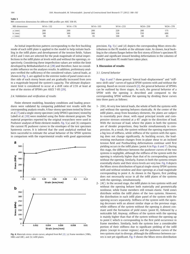
Table 3RBS connection dimensions for different HBE profiles per AISC 358‐05.
RBS dimensions W14×132 W14×176 W14×193 W14×233 W24×250 W24×370
a (mm) 200 200 200 220 200 175b (mm) 300 300 300 330 550 600c (mm) 90 95 95 100 80 85
184 SAA. Hosseinzadeh, M. Tehranizadeh / Journal of Constructional Steel Research 77 (2012) 180–192
An Initial imperfection pattern corresponding to the first bucklingmode of each infill plate is applied in the model to help initiate buck-ling in the infill plates and development of the tension fields. Valuesof 0.5 and 3 mm are selected for the peak magnitude of initial imper-fections in the infill plates at levels with andwithout the openings, re-spectively. Considering these imperfection values are within the limitdeveloped by Behbahanifard et al. [28] and therefore, have no consid-erable influence on the analyses results. In addition, preliminary anal-yses verified the sufficiency of the considered values. Lateral loads, asshown in Fig. 3, are applied to the exterior nodes of panel zones on ei-ther side of each storey beam and are gradually increased from zeroto a magnitude beyond the system's capacity. The ultimate displace-ment limit is considered to occur at a drift ratio of 2.5% at least atone of the stories of SPSWs per ASCE 7‐05 [29].
2.4. Validation and verification of results
Finite element modeling, boundary conditions and loading proce-dures were validated by comparing published test results with thecorresponding analysis results. A four-storey specimen tested by Driveret al. [7] and a single-storey specimen (only SPSW2 specimen) tested byLubell et al. [10] were modeled using the finite element program. Thematerial properties reported by the original researchers were used inPushover analyses of finite element models. Fig. 5(a) and (b) comparesthe current FE pushover curves to the envelopes of the test specimenhysteresis curves. It is inferred that the used analytical method hasbeen successful to estimate the actual behavior of the SPSW systemsin comparison with the experimental results with good approximate
Fig. 4. Materials stress–strain curves, adopted from Ref. [2]: (a) frame members (VBEs,HBEs and LBE), and (b) infill plates.
precision. Fig. 5(c) and (d) depicts the corresponding Mises stress dis-tributions in the FE models at the ultimate state. As shown, local buck-ling in the column flanges below the first storey of Driver's specimen FEmodel and significant inward bending deformations in the columns ofLubell's specimen FE model have taken place.
3. Discussion of results
3.1. General behavior
Figs. 6 and 7 show general “lateral load–displacement” and “stiff-ness–drift ratio” curves of typical SPSW systems with and without theopening. Based on recent research [2], the general behavior of SPSWscan be outlined by three stages. As such, the general behavior of aSPSW with the opening is described and compared to thecorresponding SPSW without the opening by dividing these curvesinto three parts as follows:
1- (OA). At very low lateral loads, the whole of both the systems withand without the opening behaves elastically. At the center of theinfill plates, away from boundary elements, the plates are subjectto essentially pure shear, with equal principal tensile and com-pressive stresses oriented at a 45° angle to the direction of load.With the increase of load, where the plates in both the systemsare of slender proportions, they buckle simultaneously in com-pression. As a result, the system without the opening experiencesa big loss of stiffness, while stiffness of the system with the open-ing does not change significantly. As buckling occurs, the load-resisting mechanism changes from in-plane shear to an inclinedtension field and Postbuckling deformations continue until firstyielding occurs in the infill plates (point A in Figs. 6 and 7). Duringthis stage, the difference between the pushover curves of the twosystems is negligible, although the stiffness of the system with theopening is relatively higher than that of its corresponding systemwithout the opening. Similarly, frames in both the systems remainessentially elastic and their stress levels are very low. Fig. 8 depictsthe Mises stress distribution of typical single-storey SPSW systemswith and without window and door openings at a load magnitudecorresponding to point A. As shown in the figures, first yieldingdoes not necessarily occur in all the infill plates of the systemswith the openings, simultaneously.
2- (AC). In the second stage, the infill plates in two systems with andwithout the opening behave both materially and geometricallynonlinear, while frame members still remain elastic. Yield zonesdistribute within the infill plates of the two systems. However,the distribution in each infill plate panel of the system with theopening occurs separately. Stiffness of the system with the open-ing decreases with an almost similar slope as the previous stage,while stiffness of the system without the opening is almost con-stant until the formation of yield zones (point B), followed by anoticeable fall. Anyway, stiffness of the system with the openingis mainly higher than that of the system without the opening upto point C which is corresponding to the first yield occurrence inframe members. Similarly, both the systems lose a considerableportion of their stiffness due to significant yielding of the infillplates (except in corner regions) and the pushover curves of thetwo systems start to diverge, although the difference between cur-ves is not yet significant. Fig. 9 shows the Mises stress distribution

Fig. 5. Validation of FE model: (a) comparison of pushover analysis with test results of Driver et al. [7], (b) comparison of pushover analysis with test results of Lubell et al. [10], (c)Mises stress of FE model of Driver's specimen at the ultimate state, and (d) Mises stress of FE model of Lubell's specimen (SPSW2) at the ultimate state.
185SAA. Hosseinzadeh, M. Tehranizadeh / Journal of Constructional Steel Research 77 (2012) 180–192
of typical single-storey SPSWs with and without window and dooropenings at a load magnitude corresponding to point C. As shownin the figures, first yielding in frame members in the systems withthe openings, unlike to the system without the opening, typicallyhappens in LBE rather than HBE.
3- (CD). During the third stage, in both the systems, frames behavema-terially nonlinear and the entire infill plates even in corner regionshave fully yielded. Partial or complete plastic hinges form in framemembers and at last, the systems reach their full strength at point
Fig. 6. Typical lateral load–displacement curves of SPSWs with and without the opening.
D. In this stage, stiffness of the system with the opening is slightlyhigher than that of the corresponding system without the openingand therefore, the difference between the pushover curves of thetwo systems is partially increased. Eventually, a relatively higherstrength is observed for the system with the opening compared tothe system without the opening, at the ultimate state. The Misesstress distribution of typical single-storey SPSWs with and withoutwindow and door openings at the ultimate state is shown in
Fig. 7. Typical stiffness–displacement curves of SPSWs with and without the opening.
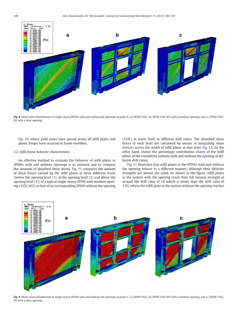
Fig. 8.Mises stress distributions in single-storey SPSWs with and without the openings at point A: (a) SPSW 1S5L, (b) SPSW 1S5L-W3 with a window opening, and (c) SPSW 1S5L-D2 with a door opening.
186 SAA. Hosseinzadeh, M. Tehranizadeh / Journal of Constructional Steel Research 77 (2012) 180–192
Fig. 10, where yield zones have spread across all infill plates andplastic hinges have occurred in frame members.
3.2. Infill-frame behavior characteristics
An effective method to evaluate the behavior of infill plates inSPSWs with and without openings is to measure and to comparethe amounts of absorbed shear storey. Fig. 11 compares the amountof shear forces carried by the infill plates at three different levels(below the opening level (1), at the opening level (2) and above theopening level (3)) of a typical single-storey SPSWwith window open-ing (1S5L-W3) to that of its corresponding SPSWwithout the opening
Fig. 9. Mises stress distributions in single-storey SPSWs with and without the openings at poD2 with a door opening.
(1S5L) at lower level at different drift ratios. The absorbed shearforces in each level are calculated by means of integrating shearstresses across the width of infill plates at that level. Fig. 12, on theother hand, shows the percentage contribution shares of the infillplates of the considered systems with and without the opening at dif-ferent drift ratios.
Fig. 11 illustrates that infill plates in the SPSWs with and withoutthe opening behave in a different manner, although their ultimatestrengths are almost the same. As shown in the figure, infill platesin the system with the opening reach their full tension strength ataround the drift ratio of 1% which is lower than the drift ratio of1.5%, where the infill plate in the system without the opening reaches
int C: (a) SPSW 1S5L, (b) SPSW 1S5L-W3 with a window opening, and (c) SPSW 1S5L-
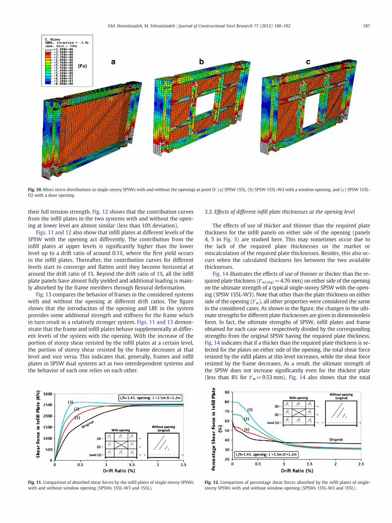
Fig. 10.Mises stress distributions in single-storey SPSWs with and without the openings at point D: (a) SPSW 1S5L, (b) SPSW 1S5L-W3 with a window opening, and (c) SPSW 1S5L-D2 with a door opening.
187SAA. Hosseinzadeh, M. Tehranizadeh / Journal of Constructional Steel Research 77 (2012) 180–192
their full tension strength. Fig. 12 shows that the contribution curvesfrom the infill plates in the two systems with and without the open-ing at lower level are almost similar (less than 10% deviation).
Figs. 11 and 12 also show that infill plates at different levels of theSPSW with the opening act differently. The contribution from theinfill plates at upper levels is significantly higher than the lowerlevel up to a drift ratio of around 0.1%, where the first yield occursin the infill plates. Thereafter, the contribution curves for differentlevels start to converge and flatten until they become horizontal ataround the drift ratio of 1%. Beyond the drift ratio of 1%, all the infillplate panels have almost fully yielded and additional loading is main-ly absorbed by the frame members through flexural deformation.
Fig. 13 compares the behavior of frames in the considered systemswith and without the opening at different drift ratios. The figureshows that the introduction of the opening and LBE in the systemprovides some additional strength and stiffness for the frame whichin turn result in a relatively stronger system. Figs. 11 and 13 demon-strate that the frame and infill plates behave supplementally at differ-ent levels of the system with the opening. With the increase of theportion of storey shear resisted by the infill plates at a certain level,the portion of storey shear resisted by the frame decreases at thatlevel and vice versa. This indicates that, generally, frames and infillplates in SPSW dual systems act as two interdependent systems andthe behavior of each one relies on each other.
Fig. 11. Comparison of absorbed shear forces by the infill plates of single-storey SPSWswith and without window opening (SPSWs 1S5L-W3 and 1S5L).
3.3. Effects of different infill plate thicknesses at the opening level
The effects of use of thicker and thinner than the required platethickness for the infill panels on either side of the opening (panels4, 5 in Fig. 3) are studied here. This may sometimes occur due tothe lack of the required plate thicknesses on the market ormiscalculation of the required plate thicknesses. Besides, this also oc-curs when the calculated thickness lies between the two availablethicknesses.
Fig. 14 illustrates the effects of use of thinner or thicker than the re-quired plate thickness (t′w(req)=4.76 mm) on either side of the openingon the ultimate strength of a typical single-storey SPSWwith the open-ing (SPSW 1S5L-W3). Note that other than the plate thickness on eitherside of the opening (t′w), all other properties were considered the samein the considered cases. As shown in the figure, the changes in the ulti-mate strengths for different plate thicknesses are given in dimensionlessform. In fact, the ultimate strengths of SPSW, infill plates and frameobtained for each case were respectively divided by the correspondingstrengths from the original SPSW having the required plate thickness.Fig. 14 indicates that if a thicker than the required plate thickness is se-lected for the plates on either side of the opening, the total shear forceresisted by the infill plates at this level increases, while the shear forceresisted by the frame decreases. As a result, the ultimate strength ofthe SPSW does not increase significantly even for the thickest plate(less than 8% for t′w=9.53 mm). Fig. 14 also shows that the total
Fig. 12. Comparison of percentage shear forces absorbed by the infill plates of single-storey SPSWs with and without window opening (SPSWs 1S5L-W3 and 1S5L).

Fig. 13. Comparison of absorbed shear forces by the surrounding frame members ofsingle-storey SPSWs with and without window opening (SPSWs 1S5L-W3 and 1S5L).
Table 4Infill/frame shares on the story shear at lower level of a single-storey SPSW with L/h=1.43 and specific window opening (L′=1.5 m and h′=1.2 m) for different LBEprofiles.
LBEsection
Infill(KN)
Frame(KN)
SPSW=infill+frame (KN)
Difference (KN)
Infill Frame SPSW
W10×77 2505 6516 9021 +3 +999 +1001W8×48a 2502 5517 8019 0 0 0W8×24 2392 4865 7257 −110 −652 −762W4×13 2187 4723 6910 −315 −794 −1109
a Designed LBE section.
188 SAA. Hosseinzadeh, M. Tehranizadeh / Journal of Constructional Steel Research 77 (2012) 180–192
shear force resisted by the infill plates does not increase proportionallywith the increase of the plate thickness. This is, in fact, because of therelatively lower stiffness and strength of the SPSW immediately aboveand below the opening and the limitation of the stiffness and strengthof the LBE. Thus, the full tension strength of thicker infill plates at theopening level is not realized even at the ultimate state. Contrarily, if athinner than the required plate thickness is selected for the plates on ei-ther side of the opening, the total shear force resisted by the infill platesat this level decreases proportionally with the decrease of the platethickness. As a result, some additional shear forces undesirably imposedon theVBEs at this level, and the ultimate strength of the systempartial-ly decreases (about 12% for extremely thin plate t′w=0).
Table 5Summary of the ultimate strengths of different SPSWs with and without openings.
SPSWs without openings SPSWs with openings
Name SPSW(KN)
Infilla
(KN)Framea
(KN)Name SPSW
(KN)Infilla
(KN)Framea
(KN)
1S3L 4746 1425 3321 1S5L-W1 8239 2510 57291S4L 5597 1960 3637 1S3L-W2 6057 1482 45751S5L 6885 2505 4380 1S4L-W2 6573 1950 46231S6L 9587 3050 6537 1S5L-W2 8103 2498 56051S7L 12,632 3544 9088 1S6L-W2 10,996 3074 79222S5L 6602 2501 4100 1S7L-W2 13,662 3575 10,0873S5L 6185 2509 3676 1S5L-W3 8019 2517 55024S3L 3727 1417 2310 1S5L-W4 8084 2489 55954S4L 4582 1950 2632 1S5L-W5 8177 2527 5650
3.4. Effects of various LBE sizes
In this section, the effects of use of one section bigger (i.e. W10×77)and two sections smaller (i.e.W8×24 andW4×13) than required section(i.e.W8×48) for the LBE in a typical single-storey SPSWwith the opening(SPSW 1S5L-W3) are studied. Other than the LBE sizes, all other proper-ties were considered the same in the considered cases. Table 4 presentsthe infill/frame participation shares on the system ultimate strength fordifferent LBE sizes. Shear forces absorbed by frames and infill plates arepresented for the lower level of the systems. The results indicate that ifa bigger than the required section is selected for the LBE, an increase inthe system ultimate strength only due to the increase in the ultimatestrength of the frame occurs. On the contrary, if a weaker than the re-quired profile is selected for the LBE, a reduction in the system ultimatestrength not only due to the reduction in the ultimate strength of theframe but also due to the reduction in the ultimate strength of the infillplates occurs. Indeed, the surrounding LBE around the panels due to pre-mature yielding or excessive deformationwere not capable of developing
Fig. 14. Effect of thickness of infill plats on either side of the opening on the systemstrength.
the full tension strength of the plates, which in turn caused aweakness inplate action and correspondingly, increased the demands on boundaryframe members in an unsuitable manner.
3.5. Effects of the opening geometry, location and type
The effects of opening geometry and type are considered by compar-ing the behavior of several single-storey SPSWs with an aspect ratio of1.43 and various window (SPSWs 1S5L-W1, 1S5L-W2, 1S5L-W3, 1S5L-W4, 1S5L-W5 and 1S5L-W6) and door-type openings (SPSWs 1S5L-D1,1S5L-D2 and 1S5L-D3). In the case of window-type openings, differentopening heights (i.e. h′=0.9, 1.2 and 1.5 m) and lengths (i.e. L′=0.9,1.2, 1.5 and 1.8 m) and in the case of door-type openings, a constantopening height (i.e. h′=2.1 m) and different opening lengths (L′=1.0,1.3 and 1.6 m) were considered. Except the LBE sizes and thickness ofpanels on either side of the openings resulted from different opening ge-ometries, other properties were similar in all the considered cases (seeTable 2). A summary of the ultimate strengths of all SPSWs with andwithout openings are presented in Table 5. Comparison of the results inTable 5 for the above cases indicates that the behavior of the SPSWswith stiffened openings is not affected much by the opening types and
4S5L 5617 2519 3098 1S5L-W6 8062 2502 55604S6L 6945 3055 3890 1S5L-D1 8538 2600 59384S7L 8333 3539 4763 1S5L-D2 8330 2408 59226S5L 7328 3408 3920 1S5L-D3 8194 2267 59278S5L 8744 4597 4147 2S5L-W3 7925 2519 5406
3S5L-W3 7484 2553 49314S3L-W2 4835 1497 33384S4L-W2 5694 2022 36724S5L-W2 6897 2577 43204S5L-W3 6888 2560 43284S5L-W3(1) 6386 2623 37634S5L-W3(2) 6145 2513 36324S5L-W3(3) 5851 2503 33484S5L-W3(4) 5636 2494 31424S5L-W3(3,4) 5946 2525 34214S5L-W3(2,3,4) 6447 2537 39104S6L-W2 8370 3071 52994S7L-W2 9571 3543 60286S5L-W3 9197 3586 56118S5L-W3 11,146 4965 6181
a Shear forces in the infill plates and frames are presented for the lower level.
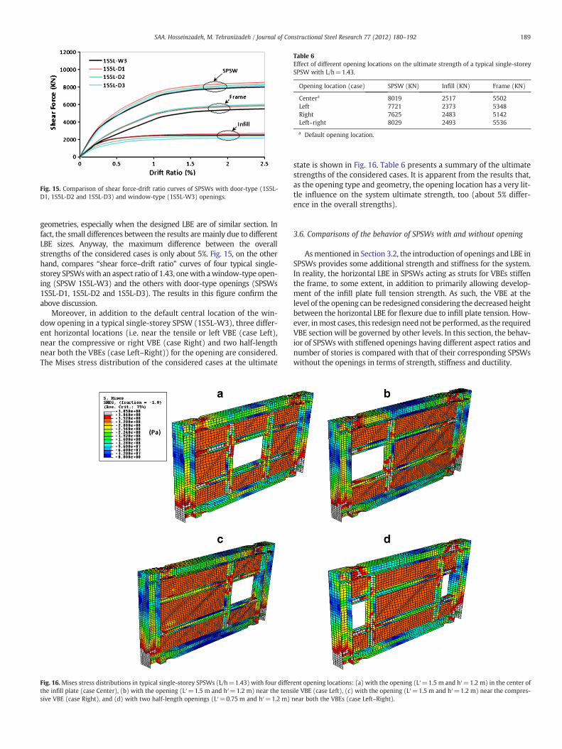
Fig. 15. Comparison of shear force-drift ratio curves of SPSWs with door-type (1S5L-D1, 1S5L-D2 and 1S5L-D3) and window-type (1S5L-W3) openings.
Table 6Effect of different opening locations on the ultimate strength of a typical single-storeySPSW with L/h=1.43.
Opening location (case) SPSW (KN) Infill (KN) Frame (KN)
Centera 8019 2517 5502Left 7721 2373 5348Right 7625 2483 5142Left–right 8029 2493 5536
a Default opening location.
189SAA. Hosseinzadeh, M. Tehranizadeh / Journal of Constructional Steel Research 77 (2012) 180–192
geometries, especially when the designed LBE are of similar section. Infact, the small differences between the results aremainly due to differentLBE sizes. Anyway, the maximum difference between the overallstrengths of the considered cases is only about 5%. Fig. 15, on the otherhand, compares “shear force–drift ratio” curves of four typical single-storey SPSWswith an aspect ratio of 1.43, onewith awindow-type open-ing (SPSW 1S5L-W3) and the others with door-type openings (SPSWs1S5L-D1, 1S5L-D2 and 1S5L-D3). The results in this figure confirm theabove discussion.
Moreover, in addition to the default central location of the win-dow opening in a typical single-storey SPSW (1S5L-W3), three differ-ent horizontal locations (i.e. near the tensile or left VBE (case Left),near the compressive or right VBE (case Right) and two half-lengthnear both the VBEs (case Left–Right)) for the opening are considered.The Mises stress distribution of the considered cases at the ultimate
Fig. 16.Mises stress distributions in typical single-storey SPSWs (L/h=1.43) with four differthe infill plate (case Center), (b) with the opening (L′=1.5 m and h′=1.2 m) near the tenssive VBE (case Right), and (d) with two half-length openings (L′=0.75 m and h′=1.2 m)
state is shown in Fig. 16. Table 6 presents a summary of the ultimatestrengths of the considered cases. It is apparent from the results that,as the opening type and geometry, the opening location has a very lit-tle influence on the system ultimate strength, too (about 5% differ-ence in the overall strengths).
3.6. Comparisons of the behavior of SPSWs with and without opening
Asmentioned in Section 3.2, the introduction of openings and LBE inSPSWs provides some additional strength and stiffness for the system.In reality, the horizontal LBE in SPSWs acting as struts for VBEs stiffenthe frame, to some extent, in addition to primarily allowing develop-ment of the infill plate full tension strength. As such, the VBE at thelevel of the opening can be redesigned considering the decreased heightbetween the horizontal LBE for flexure due to infill plate tension. How-ever, inmost cases, this redesign neednot be performed, as the requiredVBE section will be governed by other levels. In this section, the behav-ior of SPSWs with stiffened openings having different aspect ratios andnumber of stories is compared with that of their corresponding SPSWswithout the openings in terms of strength, stiffness and ductility.
ent opening locations: (a) with the opening (L′=1.5 m and h′=1.2 m) in the center ofile VBE (case Left), (c) with the opening (L′=1.5 m and h′=1.2 m) near the compres-near both the VBEs (case Left–Right).

Fig. 18. Variations of the ultimate strength ratios of frame, infill plate and SPSW withnumber of storey for SPSWs with L/h=1.43 and specific window openings at everylevel (L′=1.5 m, h′=1.2 m).
190 SAA. Hosseinzadeh, M. Tehranizadeh / Journal of Constructional Steel Research 77 (2012) 180–192
3.6.1. System strength
3.6.1.1. Different aspect ratios (L/h=0.86~2). Fig. 17 shows the variationsof the ultimate strength ratios of SPSWswith one and four stories (n=1and 4) and specific window openings at every level (L′=h′=1.2 m) tothat of their corresponding SPSWs without the openings at the first sto-rey versus aspect ratio. The results confirm that the infill plate strengthsin the SPSWs of different aspect ratios with and without the openingsare almost the same. The ultimate strength of the frames due to the in-troduction of the openings and LBE is always increased, although theratio of the increase in the frame ultimate strength is generally de-creased with the aspect ratio. As a result, the ultimate strength of theSPSWs with the openings is always higher than that of theircorresponding SPSWs without the openings and the strength ratios de-crease from 1.28 to 1.08 and 1.30 to 1.15, respectively, for the single andfour-storey SPSWs, with the increase of the aspect ratio from 0.86 to 2.
3.6.1.2. Different number of stories (n=1~8). Fig. 18 shows the variationsof the ultimate strength ratios of SPSWs with an aspect ratio of 1.43 andspecific window openings at every level (L′=1.5 m, h′=1.2 m) to thatof their corresponding SPSWs without the openings at the first storeyversus number of storey. The results show that, the ultimate strengthof the infill plates due to the introduction of the openings for theSPSWs with one to four stories (n≤4), as expected, is almostunchanged. However, a slight increase in the ultimate strength of theinfill plates of the taller SPSWs (i.e. n=6 and 8) is observed (up to8%). The ultimate strength ratio of the frames increases from 1.25 forthe shortest SPSW to 1.49 for the tallest SPSW. As a result, the ultimatestrength ratio of the SPSWs does not increase significantly with theheight of the system. Base on the results in Fig. 18, an average increaseof 22% in terms of system strength due to the introduction of the open-ings in the SPSWs of one to eight stories and with an aspect ratio of 1.43is observed.
a) Single-storey SPSWs.
b) Four-storey SPSWs.
Fig. 17. Variations of the ultimate strength ratios of frame, infill plate and SPSWwith aspectratio for single and four-storey SPSWs with specific window opening (L′=h′=1.2 m).
The situation where the openings were not required to repeat atevery level and thus, introduced only at arbitrary level(s) was alsoexamined through the analyses of eight different four-storey cases.It was assumed that all the SPSWs had an aspect ratio of 1.43, andall the openings had a similar type and geometry (window-typewith L′=1.5 m and h′=1.2 m). In four cases, the openings were as-sumed to introduce only at one level of the system (SPSWs 4S5L-W3(1), 4S5L-W3(2), 4S5L-W3(3) and 4S5L-W3(4)), and in twocases, the openings were assumed to introduce at the upper twoand at the upper three stories of the system (SPSWs 4S5L-W3(3,4)and 4S5L-W3(2,3,4), respectively). Also, two cases of without theopenings (SPSW 4S5L) and with the openings at every level (SPSW4S5L-W3) were analyzed as the lower and upper bounds, respective-ly, to the potential responses of all possible opening introductionpatterns at stories. Fig. 19 shows “base shear–roof displacement”curves for the considered cases. As shown in the figures, the behaviorof SPSWs with different patterns of opening introduction at storiesdepending on both the number and location of stories with the open-ings lies between the upper and lower bound cases. The behavior ofthe system is much influenced by the introduction of the opening atleast at the first or second level of the system, whereas the introduc-tion of the opening at the third or especially fourth level has a mini-mal effect.
3.6.2. Stiffness and ductilityAs mentioned in Section 3.1, SPSWs without the openings due to
early buckling of their infill plates at very early stages of loading(less than a drift ratio of around 0.03%) experience a significant lossof stiffness. In fact, the introduction of openings and LBE, especiallyin SPSWs with large openings and normal aspect ratios, separatesthe infill plates into the smaller subpanels which are normally of slen-der proportions, behave almost separately and have slenderness
Fig. 19. Comparison of base shear-roof displacement curves of four-storey SPSWs withL/h=1.43 for different opening introduction patterns at arbitrary level(s) for windowopenings of L′=1.5 m and h′=1.2 m.
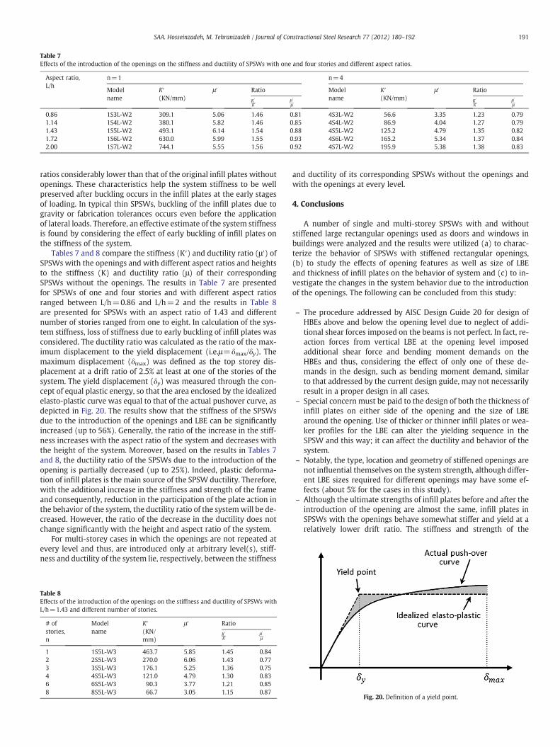
Table 7Effects of the introduction of the openings on the stiffness and ductility of SPSWs with one and four stories and different aspect ratios.
Aspect ratio,L/h
n=1 n=4
Modelname
K′(KN/mm)
μ′ Ratio Modelname
K′(KN/mm)
μ′ Ratio
K ′
Kμ′
μK ′
Kμ ′
μ
0.86 1S3L-W2 309.1 5.06 1.46 0.81 4S3L-W2 56.6 3.35 1.23 0.791.14 1S4L-W2 380.1 5.82 1.46 0.85 4S4L-W2 86.9 4.04 1.27 0.791.43 1S5L-W2 493.1 6.14 1.54 0.88 4S5L-W2 125.2 4.79 1.35 0.821.72 1S6L-W2 630.0 5.99 1.55 0.93 4S6L-W2 165.2 5.34 1.37 0.842.00 1S7L-W2 744.1 5.55 1.56 0.92 4S7L-W2 195.9 5.38 1.38 0.83
191SAA. Hosseinzadeh, M. Tehranizadeh / Journal of Constructional Steel Research 77 (2012) 180–192
ratios considerably lower than that of the original infill plates withoutopenings. These characteristics help the system stiffness to be wellpreserved after buckling occurs in the infill plates at the early stagesof loading. In typical thin SPSWs, buckling of the infill plates due togravity or fabrication tolerances occurs even before the applicationof lateral loads. Therefore, an effective estimate of the system stiffnessis found by considering the effect of early buckling of infill plates onthe stiffness of the system.
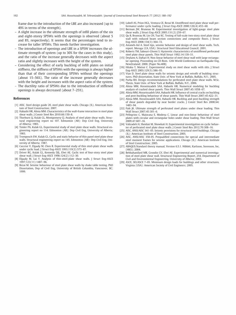
Tables 7 and 8 compare the stiffness (K′) and ductility ratio (μ′) ofSPSWs with the openings and with different aspect ratios and heightsto the stiffness (K) and ductility ratio (μ) of their correspondingSPSWs without the openings. The results in Table 7 are presentedfor SPSWs of one and four stories and with different aspect ratiosranged between L/h=0.86 and L/h=2 and the results in Table 8are presented for SPSWs with an aspect ratio of 1.43 and differentnumber of stories ranged from one to eight. In calculation of the sys-tem stiffness, loss of stiffness due to early buckling of infill plates wasconsidered. The ductility ratio was calculated as the ratio of the max-imum displacement to the yield displacement (i.e.μ=δmax/δy). Themaximum displacement (δmax) was defined as the top storey dis-placement at a drift ratio of 2.5% at least at one of the stories of thesystem. The yield displacement (δy) was measured through the con-cept of equal plastic energy, so that the area enclosed by the idealizedelasto-plastic curve was equal to that of the actual pushover curve, asdepicted in Fig. 20. The results show that the stiffness of the SPSWsdue to the introduction of the openings and LBE can be significantlyincreased (up to 56%). Generally, the ratio of the increase in the stiff-ness increases with the aspect ratio of the system and decreases withthe height of the system. Moreover, based on the results in Tables 7and 8, the ductility ratio of the SPSWs due to the introduction of theopening is partially decreased (up to 25%). Indeed, plastic deforma-tion of infill plates is the main source of the SPSW ductility. Therefore,with the additional increase in the stiffness and strength of the frameand consequently, reduction in the participation of the plate action inthe behavior of the system, the ductility ratio of the systemwill be de-creased. However, the ratio of the decrease in the ductility does notchange significantly with the height and aspect ratio of the system.
For multi-storey cases in which the openings are not repeated atevery level and thus, are introduced only at arbitrary level(s), stiff-ness and ductility of the system lie, respectively, between the stiffness
Table 8Effects of the introduction of the openings on the stiffness and ductility of SPSWs withL/h=1.43 and different number of stories.
# ofstories,n
Modelname
K′(KN/mm)
μ′ Ratio
K ′
Kμ ′
μ
1 1S5L-W3 463.7 5.85 1.45 0.842 2S5L-W3 270.0 6.06 1.43 0.773 3S5L-W3 176.1 5.25 1.36 0.754 4S5L-W3 121.0 4.79 1.30 0.836 6S5L-W3 90.3 3.77 1.21 0.858 8S5L-W3 66.7 3.05 1.15 0.87
and ductility of its corresponding SPSWs without the openings andwith the openings at every level.
4. Conclusions
A number of single and multi-storey SPSWs with and withoutstiffened large rectangular openings used as doors and windows inbuildings were analyzed and the results were utilized (a) to charac-terize the behavior of SPSWs with stiffened rectangular openings,(b) to study the effects of opening features as well as size of LBEand thickness of infill plates on the behavior of system and (c) to in-vestigate the changes in the system behavior due to the introductionof the openings. The following can be concluded from this study:
– The procedure addressed by AISC Design Guide 20 for design ofHBEs above and below the opening level due to neglect of addi-tional shear forces imposed on the beams is not perfect. In fact, re-action forces from vertical LBE at the opening level imposedadditional shear force and bending moment demands on theHBEs and thus, considering the effect of only one of these de-mands in the design, such as bending moment demand, similarto that addressed by the current design guide, may not necessarilyresult in a proper design in all cases.
– Special concern must be paid to the design of both the thickness ofinfill plates on either side of the opening and the size of LBEaround the opening. Use of thicker or thinner infill plates or wea-ker profiles for the LBE can alter the yielding sequence in theSPSW and this way; it can affect the ductility and behavior of thesystem.
– Notably, the type, location and geometry of stiffened openings arenot influential themselves on the system strength, although differ-ent LBE sizes required for different openings may have some ef-fects (about 5% for the cases in this study).
– Although the ultimate strengths of infill plates before and after theintroduction of the opening are almost the same, infill plates inSPSWs with the openings behave somewhat stiffer and yield at arelatively lower drift ratio. The stiffness and strength of the
Fig. 20. Definition of a yield point.
192 SAA. Hosseinzadeh, M. Tehranizadeh / Journal of Constructional Steel Research 77 (2012) 180–192
frame due to the introduction of the LBE are also increased (up to49% in terms of the strength).
– A slight increase in the ultimate strength of infill plates of the sixand eight-storey SPSWs with the openings is observed (about 5and 8%, respectively). It seems that the percentages tend to in-crease for taller SPSWs. This needs further investigation.
– The introduction of openings and LBE in a SPSW increases the ul-timate strength of system (up to 30% for the cases in this study),and the ratio of the increase generally decreases with the aspectratio and slightly increases with the height of the system.
– Considering the effect of early buckling of infill plates on initialstiffness, the stiffness of SPSWs with the openings is always higherthan that of their corresponding SPSWs without the openings(about 15–56%). The ratio of the increase generally decreaseswith the height and increases with the aspect ratio of the system.
– The ductility ratio of SPSWs due to the introduction of stiffenedopenings is always decreased (about 7–25%).
References
[1] AISC. Steel design guide 20, steel plate shear walls. Chicago (IL). American Insti-tute of Steel Construction; 2007.
[2] Habashi HR, Alinia MM. Characteristics of the wall-frame interaction in steel plateshear walls. J Constr Steel Res 2010;66:150–8.
[3] Thorburn LJ, Kulak GL, Montgomery CJ. Analysis of steel plate shear walls. Struc-tural engineering report no 107. Edmonton (AB): Dep Civil Eng, Universityof Alberta; 1983.
[4] Timler PA, Kulak GL. Experimental study of steel plate shear walls. Structural en-gineering report no 114. Edmonton (AB): Dep Civil Eng, University of Alberta;1983.
[5] Tromposch EW, Kulak GL. Cyclic and static behavior of thin panel steel plate shearwalls. Structural engineering report no 145. Edmonton (AB): Dep Civil Eng, Uni-versity of Alberta; 1987.
[6] Caccese V, Elgaaly M, Chen R. Experimental study of thin steel-plate shear wallsunder cyclic load. J Struct Eng-ASCE 1993;119(2):573–87.
[7] Driver RG, Kulak GL, Kennedy DJL, Elwi AE. Cyclic test of four-story steel plateshear wall. J Struct Eng-ASCE 1998;124(2):112–30.
[8] Elgaaly M, Lui Y. Analysis of thin-steel-plate shear walls. J Struct Eng-ASCE1997;123(11):1487–96.
[9] Rezai M. Seismic behaviour of steel plate shear walls by shake table testing. PhDDissertation, Dep of Civil Eng, University of British Columbia, Vancouver, BC;1999.
[10] Lubell AS, Prion HGL, Ventura CE, Rezai M. Unstiffened steel plate shear wall per-formance under cyclic loading. J Struct Eng-ASCE 2000;126(4):453–60.
[11] Berman JW, Bruneau M. Experimental investigation of light-gauge steel plateshear walls. J Struct Eng-ASCE 2005;131(2):259–67.
[12] Qu B, Bruneau M, Lin CH, Tsai KC. Testing of full-scale two-story steel plate shearwall with reduced beam section connections and composite floors. J StructEng-ASCE 2008;134(3):364–72.
[13] Astaneh-Asl A. Steel tips, seismic behavior and design of steel shear walls. Tech.report. Moraga (CA, USA): Structural Steel Educational Council; 2001.
[14] Roberts TM, Sabouri-Ghomi S. Hysteretic characteristics of unstiffened perforatedsteel plate shear panels. Thin Wall Struct 1992;14:139–51.
[15] Deylami A, Daftari H. Non-linear behavior of steel shear wall with large rectangu-lar opening. Proceeding on CD-Rom. 12th World Conference on Earthquake Eng,NewZealand; 2000. [Paper No.408].
[16] Hitaka T, Matsui C. Experimental study on steel shear walls with slits. J StructEng-ASCE 2003;129(5):586–95.
[17] Vian D. Steel plate shear walls for seismic design and retrofit of building struc-tures. PhD dissertation, State Univ. of New York at Buffalo, Buffalo, N.Y.; 2005.
[18] Purba RH. Design recommendations for perforated steel plate shear walls. M.Sc.Thesis, State Univ. of New York at Buffalo, Buffalo, N.Y., 2006.
[19] Alinia MM, Hosseinzadeh SAA, Habashi HR. Numerical modeling for bucklinganalysis of cracked shear panels. Thin Wall Struct 2007;45:1058–67.
[20] Alinia MM, Hosseinzadeh SAA, Habashi HR. Influence of central cracks on bucklingand post-buckling behaviour of shear panels. Thin Wall Struct 2007;45:422–31.
[21] Alinia MM, Hosseinzadeh SAA, Habashi HR. Buckling and post-buckling strengthof shear panels degraded by near border cracks. J Constr Steel Res 2008;64:1483–94.
[22] Paik JK. Ultimate strength of perforated steel plates under shear loading. ThinWall Struct 2007;45:301–6.
[23] Pellegrino C, Maiorana E, Modena C. Linear and non-linear behaviour of steelplates with circular and rectangular holes under shear loading. Thin Wall Struct2009;47:607–16.
[24] Valizadeh H, Sheidaii M, Showkati H. Experimental investigation on cyclic behav-ior of perforated steel plate shear walls. J Constr Steel Res 2012;70:308–16.
[25] AISC, ANSI/AISC 341–05. Seismic provisions for structural steel buildings. Chicago(IL): American Institute of Steel Construction; 2005.
[26] AISC, ANSI/AISC 358‐05. Prequalified connections for special and intermediatesteel moment frames for seismic applications. Chicago (IL): American Instituteof Steel Construction; 2005.
[27] ABAQUS/Standard theory manual, Version 6.5.1. Hibbitt, Karlsson, Sorenson, Inc,(HKS); 2004.
[28] Behbahanifard MR, Grondin GY, Elwi AE. Experimental and numerical investiga-tion of steel plate shear wall. Structural Engineering Report, 254. Department ofCivil and Environmental Engineering, University of Alberta; 2003.
[29] ASCE, SEI/ASCE 7–05. Minimum design loads for buildings and other structures.Virginia (USA): American Society of Civil Engineers; 2005.