Embed Size (px)
Citation preview

João Francisco Cardoso Gante
Setembro de 2014
IB-DFE Techniques Applied
to Multi-Antenna Systems


IB-DFE Techniques Applied to Multi-Antenna Systems
Joao Francisco Cardoso Gante
Dissertacao para obtencao do Grau de Mestre emEngenharia Electrotecnica e de Computadores
Orientador: Doutor Marco Alexandre Cravo GomesCo-Orientador: Doutor Vıtor Manuel Mendes da Silva
JuriPresidente: Doutor Luıs Alberto da Silva CruzOrientador: Doutor Marco Alexandre Cravo GomesVogais: Doutora Lucia Maria dos Reis Albuquerque Martins
Doutor Rui Miguel Henriques Dias Morgado Dinis
Setembro de 2014


Agradecimentos
Em primeiro lugar, gostaria de agradecer ao professor Marco Gomes, ao professorVıtor Silva e ao professor Rui Dinis, nao so pela possibilidade de ter participado nesteprojeto, mas tambem pelos preciosos ensinamentos dados no decorrer do trabalho paraesta dissertacao.
Aos meus pais e a minha irma, cujo empenho desde o primeiro dia da minha existenciapermitiu que eu conseguisse atingir os meus objetivos, e ao qual estou eternamente grato.
Aos meus colegas de laboratorio, pelo otimo ambiente de trabalho proporcionado.Para alem das inumeras duvidas esclarecidas, sem eles o relogio desde ultimo ano teriaavancado lentamente.
Por ultimo, mas nao de todo menos importante, a Joana Pereira, cuja complexidadetorna uma dissertacao de mestrado num mero quebra-cabecas para criancas. Obrigadopor desafiares o modo como vejo o mundo, dia apos dia, e por me ajudares a seguir osmeus sonhos, mesmo os mais irrealistas.
A todos os que me apoiaram, pela sua paciencia e dedicacao,
Muito Obrigado.


Abstract
With the rise of data-hungry mobile services, scientists have struggled to deliver thedesired mobile data rates whilst using the limited available bandwidth. As the higher fre-quencies are yet inaccessible, namely the millimeter wave frequencies (between 60 and100 GHz), spectral efficiency is becoming the defining factor for future standards. Asresult of this, MIMO techniques have been gathering interest in the past few years. Thebasic concept of a MIMO system consists in transmitting different signals through severalantennas, using the same frequency band and with at least as many receiving antennas onthe receiver. Exploiting the lack of correlation between the multiple channels, it is pos-sible to isolate and detach each received signal at the receiver. While it seems to be astraightforward method to increase the spectral efficiency, as result of multiple signalsbeing squeezed in the same frequency band, the complexity of the signal separation al-gorithms is awfully high. Additionally, these algorithms fail to separate signals whosepower is far inferior than their peers’, imposing limitations to MIMO based systems. Thiswork proposes three independent solutions to improve MIMO uplink communicationsfor single-carrier block-based transmissions with iterative frequency domain equalization(IB-DFE). The first uses magnitude modulation techniques so as to improve the trans-mitter’s power efficiency. The second employs base station cooperation techniques toimprove the user’s performance at cell edges. Lastly, the third solution apply a cluster-based multi-user detection, allowing for an increased number of users to share the samechannel without exhausting the computational resources at the receiver.
KeywordsSignal Processing, IB-DFE, MIMO, Base Station Cooperation, Magnitude Modula-
tion, Multi-user Detection

Resumo
Com o aumento exponencial do trafego de dados por parte dos servicos moveis, acomunidade cientıfica tem tido dificuldades em desenvolver tecnicas que permitam atin-gir a capacidade de transmissao de dados moveis desejada, devido a largura de bandafısica limitada. Como as bandas de frequencias mais elevadas ainda nao estao disponıveispara uso, nomeadamente as bandas milimetricas (60 a 100 GHz), a eficiencia espectraltem-se tornado um fator chave na escolha das tecnologias adotadas. Como resultado, astecnicas MIMO tem reunido um grande interesse nos ultimos anos. O conceito basicode um sistema MIMO consiste em transmitir diferentes sinais atraves de varias antenas,com recurso a mesma gama de frequencias e com tantas ou mais antenas no lado do re-cetor. Ao tirar partido da falta de correlacao entre os multiplos canais, e possıvel isolare extrair cada um dos sinais recebidos no recetor. Apesar de parecer um metodo simplespara aumentar a eficiencia espectral, dado que os varios sinais partilham a mesma gamade frequencias, os algoritmos de separacao dos sinais no recetor tem uma complexidadeelevada. Para alem do mais, estes algoritmos sao ineficazes a extrair sinais cuja potencia econsideravelmente inferior a dos seus pares, o que por sua vez impoe algumas limitacoesna implementacao de sistemas MIMO. Esta tese propoe tres solucoes independentes paramelhoria de comunicacoes MIMO no sentido ascendente (uplink), baseadas em sistemasde transmissao de mono-portadora por bloco com equalizacao iterativa no domınio dafrequencia (IB-DFE). A primeira solucao usa a modulacao de magnitude de modo a au-mentar a eficiencia energetica dos transmissores MIMO. A segunda proposta explora acooperacao entre estacoes base, de modo a melhorar o desempenho dos utilizadores noslimites das celulas moveis. Por fim, a terceira solucao propoe a detecao de multiplos uti-lizadores agrupados em diferentes nıveis de potencia, permitindo que um numero superiorde utilizadores partilhe o mesmo canal fısico.
Palavras-ChaveProcessamento de Sinal, IB-DFE, MIMO, Cooperacao de Estacoes Base, Modulacao
de Magnitude, Detecao de Multi-utilizadores

Contents
1 Introduction 11.1 Motivation . . . . . . . . . . . . . . . . . . . . . . . . . . . . . . . . . . 2
1.2 Objectives and Main Contributions . . . . . . . . . . . . . . . . . . . . . 3
1.3 Dissertation Outline . . . . . . . . . . . . . . . . . . . . . . . . . . . . . 4
2 MIMO Concepts 52.1 Channel Capacity . . . . . . . . . . . . . . . . . . . . . . . . . . . . . . 6
2.1.1 SISO and MIMO Channel Capacity Comparison . . . . . . . . . 7
2.1.2 MIMO Channel Capacity . . . . . . . . . . . . . . . . . . . . . . 8
2.2 Signal Separation for Uplink MIMO . . . . . . . . . . . . . . . . . . . . 11
3 MIMO IB-DFE Receivers 133.1 SISO IB-DFE Receivers . . . . . . . . . . . . . . . . . . . . . . . . . . 14
3.2 Basic Structure of the MIMO IB-DFE Receivers . . . . . . . . . . . . . . 15
3.2.1 Hard IB-DFE Reliability . . . . . . . . . . . . . . . . . . . . . . 17
3.2.2 Soft IB-DFE Reliability . . . . . . . . . . . . . . . . . . . . . . 18
3.2.3 Deriving the IB-DFE coefficients . . . . . . . . . . . . . . . . . 18
3.2.4 Coding and Turbo IB-DFE . . . . . . . . . . . . . . . . . . . . . 19
4 Improved Power and Spectral Efficiencies on MIMO Systems 214.1 MIMO SC Transmission using Magnitude Modulation Techniques . . . . 22
4.1.1 Magnitude Modulation . . . . . . . . . . . . . . . . . . . . . . . 22
4.1.2 MIMO with IB-DFE and MM . . . . . . . . . . . . . . . . . . . 24
4.1.3 Simulations Results . . . . . . . . . . . . . . . . . . . . . . . . . 25
4.1.4 Final Comments . . . . . . . . . . . . . . . . . . . . . . . . . . 28
4.2 Improved Spectral Efficiency with Cooperation . . . . . . . . . . . . . . 28
4.2.1 Base Station Cooperation combined with IB-DFE . . . . . . . . . 29
4.2.2 Simulations Results . . . . . . . . . . . . . . . . . . . . . . . . . 30
4.2.3 Final Comments . . . . . . . . . . . . . . . . . . . . . . . . . . 33
4.3 Improved Spectral Efficiency with Clustering . . . . . . . . . . . . . . . 34
i

Contents
4.3.1 Clustered Multi-user Detection Through IB-DFE . . . . . . . . . 354.3.2 IB-DFE Iteration Order for Clustered Multi-User Detection . . . 374.3.3 Simulations Results . . . . . . . . . . . . . . . . . . . . . . . . . 374.3.4 Final Comments . . . . . . . . . . . . . . . . . . . . . . . . . . 41
5 Conclusions 435.1 Future Work . . . . . . . . . . . . . . . . . . . . . . . . . . . . . . . . . 44
A Accepted Paper at IEEE VTC2014-Fall 49
ii

List of Figures
2.1 Representation of a SISO channel. . . . . . . . . . . . . . . . . . . . . . 7
2.2 Representation of a MIMO channel. . . . . . . . . . . . . . . . . . . . . 7
2.3 Maximum spectral efficiency vs SNR on a 4x4 MIMO, for three levels ofcorrelation. . . . . . . . . . . . . . . . . . . . . . . . . . . . . . . . . . 9
2.4 Maximum spectral efficiency vs SNR comparison for uncorrelated channels. 10
3.1 Block diagram representation of a SISO IB-DFE receiver . . . . . . . . . 14
3.2 Detection of the pth layer, for a given iteration in MIMO IB-DFE. . . . . 15
4.1 Generic SC transmitter scheme. . . . . . . . . . . . . . . . . . . . . . . 23
4.2 Magnitude modulation principle. . . . . . . . . . . . . . . . . . . . . . . 23
4.3 General diagram of the proposed transmitter. . . . . . . . . . . . . . . . . 24
4.4 BER vs Eb/N0 performance of the uncoded IB-DFE with no MM, for dif-ferent layers at different iterations. . . . . . . . . . . . . . . . . . . . . . 26
4.5 BER vs Eb/N0 performance of the uncoded IB-DFE with MM, for differ-ent layers at different iterations. . . . . . . . . . . . . . . . . . . . . . . 26
4.6 BER vs Eb/N0 performance of the IB-DFE with turbo equalization and noMM, for different layers at different iterations. . . . . . . . . . . . . . . . 27
4.7 BER vs Eb/N0 performance of the IB-DFE with turbo equalization andMM, for different layers at different iterations. . . . . . . . . . . . . . . . 27
4.8 System representation, with P = N = 2. The MTs with 1 and 2 are theconsidered users, the ones with I are considered interference generators.It is considered that all MTs are using the same physical channel. . . . . . 29
4.9 Average BER per user vs total interference for the 4th iteration of IB-DFE,considering various values for the power per user. . . . . . . . . . . . . . 31
4.10 Average BER per user vs power per user for different iterations of IB-DFE, considering various interference levels. . . . . . . . . . . . . . . . 32
4.11 Average BER per user vs total interference for the 4th iteration of IB-DFE with LDPC coding (rate = 0.5) and turbo equalization, consideringvarious values for the power per user. . . . . . . . . . . . . . . . . . . . . 32
iii

List of Figures
4.12 Average BER per user vs total interference for the 4th iteration of IB-DFE,considering both the case with BS cooperation and the one without. . . . 33
4.13 System representation, with N = 2 and P = 4. The MTs with 1 belongto the closer cluster and the MTs with 2 belong to the distant one. It isconsidered that all MTs are using the same physical channel. . . . . . . . 35
4.14 Average BER per user vs power difference between clusters for the 4thiteration of IB-DFE on each cluster, considering various values for thepower per user in the close cluster. . . . . . . . . . . . . . . . . . . . . . 38
4.15 Average BER per user vs power difference between clusters for the 4thiteration of IB-DFE on each cluster with one extra receiving antenna (N =
3), considering various values for the power per user in the close cluster. . 394.16 Average BER per user vs power difference between clusters for the 4th
iteration of a turbo IB-DFE on each cluster, using LDPC coding with arate of 0.5 and considering various values for the power per user in theclose cluster. . . . . . . . . . . . . . . . . . . . . . . . . . . . . . . . . . 40
4.17 Average BER per user vs power difference between clusters for the 4thiteration of IB-DFE on each cluster, considering various iteration orders. . 41
iv

List of Tables
4.1 Table with the considered iteration sequences . . . . . . . . . . . . . . . 40
v

vi

List of Acronyms
3G third generation
4G fourth generation
5G fifth generation
AWGN additive white gaussian noise
BER bit error rate
BS base station
CE cyclic extension
DAC digital-to-analog converter
DFT discrete Fourier transform
FD frequency domain
FDE frequency domain equalization
HPA high power amplifier
IB-DFE iterative block decision feedback equalization
ISI intersymbol interference
LDPC low-density parity-check
LTE long-term evolution
LUT look-up table
MIMO multiple-input and multiple-output
MM magnitude modulation
vii

MPMM multistage polyphase magnitude modulation
MT mobile terminal
MU-MIMO multi-user multiple-input and multiple-output
PAPR peak-to-average power ratio
PC polar clipping
PS polar scaling
QoS quality of service
QPSK quadrature phase-shift keying
RC rectangular clipping
RRC root-raised cosine
RS rectangular scaling
SC single carrier
SIC successive interference cancellation
SISO single-input and single-output
SNIR signal to interference plus noise ratio
SNR signal-to-noise ratio
TD time domain
viii

1Introduction
Contents1.1 Motivation . . . . . . . . . . . . . . . . . . . . . . . . . . . . . . . . 2
1.2 Objectives and Main Contributions . . . . . . . . . . . . . . . . . . 3
1.3 Dissertation Outline . . . . . . . . . . . . . . . . . . . . . . . . . . . 4
1

1. Introduction
Mobile communications data usage has experienced an enormous growth burst in thelast few years. The number of smartphones is quickly rising and third generation (3G)networks widely cover most countries, some of which also have faster networks such aslong-term evolution (LTE) or LTE advanced (fourth generation (4G)). Recent studies [1]have shown that global mobile data traffic grew 81 percent in 2013 and it is expected togrow sixfold from 2014 until the end of 2018 [1]. Mobile data traffic represents morethan half of the total data traffic and 2013’s mobile data traffic was nearly 18 times thesize of the entire global Internet in 2000. These crushing numbers show that the capacitymust be increased, in order to keep (or to improve) the existing mobile communications’quality of service (QoS).
1.1 Motivation
The easiest mean to achieve a higher capacity of a given system, which in turn canlead to a better QoS through better and faster services, would be to increase the usedphysical bandwidth, as the achievable maximum bit rate is directly proportional to it.However, the available bandwidth is extremely limited, with the higher frequencies notyet occupied being impossible to use as of now. Even though future standards (i.e. thefifth generation (5G)) hope to lift this constraint [2], they won’t come up fast enoughto be the answer to our society’s very short-term needs. The solution to our problemconsists then on improving the existing spectral efficiency or, in other words, to squeeze ahigher data rate in the same available bandwidth. There are two different means to do so:either the individual communication links are improved or the overall system capacity isupgraded with more links. Unfortunately, the individual link capacities are already closeto the fundamental Shannon limit, so, further improvements are mostly restricted to theoverall system’s capacity [3] [4].
Multiple-input and multiple-output (MIMO) systems are indeed a great answer to theincreasing mobile data usage [5] [6]. By allowing more individual links to coexist in thesame physical channel, the overall spectral efficiency can increase up to as many times asthe minimum between the number of simultaneously transmitted signals and the numberof receiving antennas, without increasing the total transmitted power1 [7]. However, aseach receiving antenna contains tangled information regarding all the transmitted signals,a complete recovery of those signals requires signal separation techniques. The signalseparation of a MIMO system is a very complex and highly demanding operation. Addi-tionally, it must be executed alongside the equalization (as it will be soon discussed) and,
1Alternatively, it is possible to keep the overall spectral efficiency, while decreasing the total transmittedpower.
2

1.2 Objectives and Main Contributions
therefore, the equalizer of a MIMO system must be slightly different than single-inputand single-output (SISO)’s equalizer [8] [9] [10].
A useful generalization of a MIMO system is the multi-user multiple-input and multiple-output (MU-MIMO) system. While in a MIMO system both communicating sides con-sist of a single device with multiples antennas, in a MU-MIMO the multiple antennas arespread among several devices [11]. As a MIMO equalizer is oblivious of the signal’s ori-gin, the same equalization scheme can be used for both MIMO and MU-MIMO. A clearexample of a MU-MIMO would be a telecommunications cell with a base station (BS)connected with several mobile terminals (MTs) through the same physical channel, a sys-tem whose overall uplink spectral efficiency gain and computational effort would be thesame as if the MTs were a single device with the same total transmitted power [12] [13].Nevertheless, while a multi-antenna transmitter in a MIMO (or MU-MIMO) can bothdecrease its total transmitted power and increase its data throughput, a given MT with asingle transmitting antenna must keep its transmitted power so as to keep its individualdata throughput.
A robust MIMO (or MU-MIMO) equalization is then of utmost importance. It bringsforth not only the desired enhanced spectral efficiency, but also allows for a higher trans-mitting power efficiency for the battery-limited mobile users with multiple antennas, cul-minating in a better overall mobile communications system.
1.2 Objectives and Main Contributions
After this brief analysis, it became clear how relevant it would be to study uplinkMIMO equalization, namely how to increase both power and spectral efficiency. All theproposed changes are applied to the promising iterative block decision feedback equal-ization (IB-DFE) scheme, aiming to quantify the magnitude improvement on state of theart equalization techniques. For that very reason, the implementation of channel codingis also tested for every scenario.
Regarding the power efficiency, it was applied a magnitude modulation (MM) tech-nique at the MIMO transmitter. As the MM scales down the symbols whose output af-ter pulse shaping filter is higher than a given threshold, the peak-to-average power ra-tio (PAPR) at each transmitting antenna is restrained. As result, the transmitter’s powerefficiency was considerably increased, while introducing minimal distortion to the trans-mitted symbols. This led to one accepted paper on the Vehicular Technology Conference2014-Fall [14].
To tackle the spectral efficiency issue, situations with base station cooperation andclustering were exploited. By employing base station cooperation schemes, it is possible
3

1. Introduction
to make use of MIMO’s channel diversity properties when working with mobile userssharing the same cell edges, greatly reducing the minimum power requirements while in-creasing the spectral efficiency. Regarding the clustering of users, it is proved that if on agiven physical channel there are clusters of users with enough power difference betweenthem at the receiver, it is possible to successfully detect all the users. This method notonly gives room for increased spectral efficiency, but also reduces the total computationaleffort needed. Each one of these techniques lead to a submitted paper, to the VehicularTechnology Conference 2015-Spring [15] and to the International Conference on Com-munications [16]
1.3 Dissertation Outline
This thesis is organized in five chapters. Succeeding the introduction, Chapter 2 willprovide an overview on MIMO and MU-MIMO systems, where its benefits and limita-tions on the overall communication system are elucidated. Chapter 3 lays emphasis onthe IB-DFE scheme, where careful attention is payed to mathematical formulation of theequalizer and its relationship with channel coding. Chapter 4 not only studies the powerefficiency improvement at the MIMO transmitter using MM techniques, but also aims toimprove the MU-MIMO spectral efficiency through user clustering and BS cooperation.Finally, Chapter 5 discusses the main conclusions drawn from this thesis work.
As a side note, most of the mathematical proofs in chapter 2 are shown in a verysummarized manner, so as to enlighten a unacquainted reader about the potentials of thosetechniques. The mathematical aspects of this chapter are quite extensive and, therefore, ifthe reader desires to fully understand the matter, it is suggested the reading of the suppliedbibliography.
4

2MIMO Concepts
Contents2.1 Channel Capacity . . . . . . . . . . . . . . . . . . . . . . . . . . . . 6
2.2 Signal Separation for Uplink MIMO . . . . . . . . . . . . . . . . . . 11
5

2. MIMO Concepts
The use of multiple antennas at the transmitter and receiver in wireless systems,known as MIMO technology, has rapidly gained in popularity over the past decade due toits powerful performance-enhancing capabilities. Those performance-enhancing capabil-ities come from:
• Beamforming gain — the capacity of adding coherently the different transmittedsignals at specific locations, so as to simultaneously increase the signal to inter-ference plus noise ratio (SNIR) at the desired receivers while minimizing it forundesired receivers;
• Spatial diversity gain — sending the same signal through several links decreasesthe probability of that given signal to be critically faded at the receiver;
• Spatial multiplexing gain — it is possible to send different information throughdifferent transmitting antennas.
In general, it may not be possible to exploit simultaneously all the benefits describedabove due to conflicting demands on the spatial degrees of freedom [17]. However, us-ing some combination of the benefits across a wireless network will result in improvedcapacity, as detailed in the following section.
2.1 Channel Capacity
In 1948, Claude Shannon completed an information theory law left by Ralph Hart-ley [3]. The resulting Shannon-Hartley theorem, shown in equation (2.1), specifies themaximum bit rate at which information can be transmitted over a single communicationchannel with a given bandwidth B, as function of the signal-to-noise ratio (SNR). If agiven system has a throughput lower than this limit, it can be transmitted with asymptoti-cally small probability of error.
C = B log2 (1+SNR) (2.1)
Equation 2.1 proves that a SISO link has a maximum spectral efficiency (C/B) forgiven SNR. While it is possible to increase the maximum spectral efficiency of the linksthrough extra signal power, mobile devices would have to drain power from their batter-ies several times faster in order to achieve a considerable gain. As an example, a linkwhose SNR is of 10dB would need to increase his power tenfold in order to achieve amaximum spectral efficiency almost twice as high, due to the logarithmic nature of therelationship. The solution to boost the real spectral efficiency of a given link without in-creasing the transmitted power is then restricted to apply techniques such as coding and
6

2.1 Channel Capacity
signal processing [3], so as to approach as much as possible its maximum theoreticalvalue. However, even that solution is close to its saturation point for several scenarios, asshown in [4].
2.1.1 SISO and MIMO Channel Capacity Comparison
Considering a narrowband frequency flat fading channel without time dispersion, aSISO link can be represented as in Fig. 2.1.
Figure 2.1: Representation of a SISO channel.
Here, the time domain signal at the receiver for a given instant is given by
y = hx+n , (2.2)
where y is the received signal, h is the channel response, x is the transmitted signal and n isthe additive white gaussian noise (AWGN) channel noise. Note that it is not a convolution,as the channel has no time dispersion. If the channel response is known, it is easy toobtain an estimation of the transmitted signal through the received signal, dividing y by h.Extending the SISO paradigm, it is clear that to increase capacity, one can just replicatethe link T times1, sending all the information through the same physical channel as shownin Fig. 2.2.
Figure 2.2: Representation of a MIMO channel.
1A new link corresponds to one additional transmitting-receiving antenna pair
7

2. MIMO Concepts
In a MIMO scheme, the equivalent representation is given by
y = Hx+n , (2.3)
where y and x are column vectors with the signal at the receivers and transmitters, respec-tively, n is the channel noise vector, and H is a matrix with all the time domain channelresponses, also called channel information2. Once again, if the channel information isknown, only a matrix inversion is needed so as to estimate the transmitted signal from thereceived signal (assuming that H is a non-singular square matrix). Sadly, not only a realchannel contains a combination of noise, phase shifts and time-delays, but also the trans-mitted signals’ power decreases with the distance traveled [18]. Many mobile channelsalso include awful phenomena such as multipath propagation (which results in a time dis-persion), selective frequency fading, scattering or Doppler shifts [17]. To cope with anyof this undesired effects, the recovery of the transmitted signals becomes a complexitygiant in a MIMO scenario, expanding with the number of transmitted signals.
2.1.2 MIMO Channel Capacity
Computational complexities aside, by using T MIMO links, the maximum spectralefficiency increases by up to a factor of T . However, this scheme would uses T timesthe power if the power per link is kept. Since most devices have power restrictions, theidea of using T links (with the same power per link) to get T times the maximum spectralefficiency is not much of a breakthrough. A more useful measure would be a comparisonof the channel capacity with the extra links, while keeping the total transmitted power thesame.
From [5] and [6], if both the receiver and the transmitter have access to the channel in-formation, the MIMO capacity for a system with P transmitting antennas and N receivingantennas (therefore, T is the minimum between N and P) can be given as
C = B maxTr(Rxx)=P
log2 det(
IN +SNR
PHRxxHH
), (2.4)
where Tr denotes the trace operator, Rxx the autocorrelation matrix of the transmittedsignal3, det is the determinant of a square matrix, IN is an identity matrix with size N andSNR is the global SNR of the system. The Rxx can also be seen as the power distributionamong the transmitters and, as the transmitted signals are independent most of the times,it is a diagonal matrix.
2In this section, for the sake of a coherent explanation and to differentiate from the SISO channel, boldcapital H is used to represent the time domain MIMO channel, instead of being the frequency domainrepresentation of the channel response, as will be denoted in the following chapters.
3The autocorrelation matrix of a given vector x is given by Rxx = E{
xxH}
, with E {} denoting theexpectation operator
8

2.1 Channel Capacity
Typically, the total power is distributed by the transmitting antennas according to thechannel conditions [17]. However, if the transmitter doesn’t possess the channel informa-tion, it is assumed an equal power distribution among the transmitters, in which case Rxx
is an identity matrix and equation (2.4) becomes
C = Blog2 det(
IN +SNR
PHHH
). (2.5)
Assuming that HHH is normalized (i.e. the square of the diagonal elements is 1), withfurther mathematical simplifications (as in [19] and [17]) equation (2.5) becomes
C = BT log2 (1+SNR)+Blog2 det(Rch) , (2.6)
where Rch is the normalized channel correlation matrix, such as its elements∣∣ri, j∣∣≤ 1 and
ri, j = ∑k
hi,kh∗k, j . (2.7)
Knowing the maximum value that each element can take, it becomes clear that det(Rch)
is at most 1 and, therefore, channel correlation degrades the maximum spectral efficiency(as shown in Fig. (2.3)). At a first, light approach, the previous statement seems bothobvious and contradictory. From one side, when the channels are correlated, then clearlywe have less information to exploit and, therefore, an overall worse performance. From
Figure 2.3: Maximum spectral efficiency vs SNR on a 4x4 MIMO, for three levels ofcorrelation (low = 0%, medium = 20% and high = 40%) [17].
9

2. MIMO Concepts
the other, an uncorrelated channel requires the presence of nefarious channel effects, suchas multipath propagation (which results in a time dispersion), selective frequency fad-ing, scattering or Doppler shifts [17]. Nonetheless, going back to the most basic conceptssuch as equation (2.3), it is evident that the channel matrix needs to have both its rows andcolumns uncorrelated, as the matrix inversion would be impossible otherwise. A MIMOscheme is then a somewhat elusive system: to bring out its utter potential, it needs to beunder situations whose complexity was already very high for SISO systems [17].
If the channel information is uncorrelated, then the maximum spectral efficiency in-creases linearly with T , the minimum between the number of transmitting and receivingantennas, as shown in Fig. (2.4). Even though some assumptions were made beforereaching to equation (2.6), the generalization proves that the same conclusions can betaken [17]. Disregarding the complexity at the receivers, employing MIMO systems isthen a straightforward mean to greatly improve the spectral efficiency, while keeping thesame power consumption at the transmitter [7] [2].
Just as a final remark: for MU-MIMO, the exact same conclusions can be made.However, it has several users in the same physical channel and it is generally undesired tolower the throughput per user (when compared to a SISO channel). Therefore, it is not aslinear to compare the spectral efficiency gain when changing a given system from SISO
Figure 2.4: Maximum spectral efficiency vs SNR comparison for uncorrelated channels[17].
10

2.2 Signal Separation for Uplink MIMO
to MU-MIMO, as there will be both MIMO and total power gains.
2.2 Signal Separation for Uplink MIMO
By considering a MIMO system with a number of antennas at the receiver at leastequal to the number employed at the transmitter (i.e. P≤N), it is theoretically possible toseparate the P different signals [10]. On flat frequency fading MIMO channels the signalseparation is quite simple [10], needing only to invert the channel matrix (as describedpreviously). However, for frequency-selective channels, signal separation requires theimplementation of more complex inter-antenna interference cancellation schemes. Foroptimal performance of the interantenna interference cancellation scheme, signal separa-tion and equalization should be performed together iteratively [10]. This is easily justi-fied, considering that the for a given signal estimation it is needed an equalization and, toproduce an improved estimation through inter-antenna interference cancellation, previoussignals’ estimations are needed. In that sense, a MIMO equalizer not only compensatesthe linear distortion causer by the channel frequency selectivity, but also performs signalseparation.
The first MIMO equalizers proposed were time domain (TD) systems [20–22]. Un-fortunately, as with other TD receivers, their complexity can be quite high for severelytime-dispersive channels. On the other hand, for systems with frequency domain (FD)processing, the equalizer complexity can be kept low since most channels can be modeledas tiny parallel flat fading channels, being the recommended equalization scheme [8].Amongst the FD equalization schemes for the uplink MIMO channel, the IB-DFE hasshown the most promising results [10], being the subject of the following chapter.
11

2. MIMO Concepts
12

3MIMO IB-DFE Receivers
Contents3.1 SISO IB-DFE Receivers . . . . . . . . . . . . . . . . . . . . . . . . . 14
3.2 Basic Structure of the MIMO IB-DFE Receivers . . . . . . . . . . . 15
13

3. MIMO IB-DFE Receivers
In order to be successful, any kind of mobile communications must be able to with-stand inter-carrier and inter-symbol interference, caused by the possible strong dispersivenature of the channel. To be able to transmit over severe time-dispersive channels, the bestoption for uplink MIMO communications is to have an appropriate cyclic extension (CE)and to be combined alongside block-based frequency domain equalization (FDE) trans-mission techniques [23] [10]. For any uplink transmission, single carrier (SC) modulationschemes with FDE are proved to be the best suited [24], due to the lower peak-to-averagepower ratio (PAPR) [25] and to the possibility to replace the linear FDE with a non-linearFDE. Amongst the non-linear FDE, the IB-DFE scheme delivers the greatest gains inperformance [8] [10], being the subject of this chapter.
3.1 SISO IB-DFE Receivers
Figure 3.1: Block diagram representation of a SISO IB-DFE receiver [26].
Before the MIMO implementation of the IB-DFE algorithm, the IB-DFE existed as aSISO equalizer for block based SC transmissions [8] [10], with its main diagram beingrepresented in Fig 3.1. For a SISO system, the IB-DFE equalizer is, as described on itsown name, an iterative block decision feedback equalizer in the frequency domain. Toa given received block signal, the SISO IB-DFE algorithm would compute two sets ofcoefficients, the feedback and the feedforward coefficients, as shown in Fig. 3.1. Thefeedforward coefficients aim to equalize the channel, with the knowledge of the channelinformation, while the feedback coefficients aim to both minimize the intersymbol inter-ference (ISI) and the interference due to past incorrect estimations. Iteratively performingthis algorithm would yield a better and better estimation of that given block. Consideringthis block isolation capability, a MIMO version of this algorithm was created.
14

3.2 Basic Structure of the MIMO IB-DFE Receivers
3.2 Basic Structure of the MIMO IB-DFE Receivers
The MIMO IB-DFE receiver extends the basic SISO IB-DFE principle of residualinterference’s cancellation, based on known data estimations from feed-forward equaliza-tion. When attempting to recover the P different transmitted streams using the N receiv-ing antennas, the relationship P ≤ N is required (as explained previously). Essentially,MIMO IB-DFE [9] detects one stream at a time and cancels the interference from alreadydetected streams, a method also known as successive interference cancellation (SIC). Tomaximize this method’s effectiveness, it is desirable to rank the streams according to somequality measure (usually the average received power) and to detect the streams from thebest to the worst. That way, the interference of the stronger streams is diminished whenattempting to detect the weaker ones, which proves to be extremely difficult otherwise.This algorithm aims then to perform frequency-domain equalization while minimizing theinterference between streams, with both feedback and feedforward filters. The algorithmworks on a per-block basis, meaning that the feedback’s effectiveness to cancel all theinterferences is limited by the reliability of the detected data at previous iterations. Con-sequently, it is desired to apply more than one iteration per block, in order to successfullydetect all the streams. A general block diagram representation of the MIMO IB-DFE isshown in Fig. 3.2.
x
x
++ +-
IDFTSoft
Demod.Soft
Decod.
Soft Mapper
x
x DFT
LLRs
LLR to Soft
Symbols
DFT
If channel coding is used
Figure 3.2: Detection of the pth layer, for a given iteration in MIMO IB-DFE.
Let the time-domain blocks of length M at the pth transmitting antenna and nth re-ceiving antenna be respectively
s(p) =[s1,(p) . . . sM,(p)
]T (3.1)
15

3. MIMO IB-DFE Receivers
andy(n) =
[y(n)1 . . . y(n)M
]T, (3.2)
with p = 1, · · · ,P, and n = 1, · · · ,N and let
S(p) =[S1,(p) . . . SM,(p)
]T (3.3)
andY(n) =
[Y (n)
1 . . . Y (n)M
]T(3.4)
denote the M-point discrete Fourier transform (DFT) of s(p) and y(n), where
Sk,(p) =M−1
∑m=0
sm,(p)e(− j2πkm/M) (3.5)
and
Y (n)k =
M−1
∑m=0
y(n)m e(− j2πkm/M) , (3.6)
With Sk and Yk being respectively the P-tuple and N-tuple vectors of the obtained DFTcoefficients for each k sub-carrier, with k = 0, · · · ,M−1, given by
Sk =[Sk,(1) . . . Sk,(P)
]T (3.7)
andYk =
[Y (1)
k . . . Y (N)k
]T, (3.8)
the receiving frequency-domain signal Yk can be written as
Yk = HkSk +Nk , (3.9)
where, Hk and Nk represent respectively the frequency-domain dispersive channel andadditive white gaussian noise (AWGN) matrices, written as
Hk =
H(1)k,(1) · · · H(1)
k,(P)... . . . ...
H(N)k,(1) · · · H(N)
k,(P)
(3.10)
where H(n)k,(p) is the channel’s frequency response for the k-th carrier between the p-th
transmitter and the n-th receiver, and
Nk =[N(1)
k . . . N(N)k
]T. (3.11)
The frequency-domain soft-estimations associated with the pth layer at the output ofthe equalizer are given by
Sk = FTk Yk−BT
k S′k , (3.12)
16

3.2 Basic Structure of the MIMO IB-DFE Receivers
where the feedforward and feedback matrices are respectively
Fk =
F(1)k,(1) · · · F(1)
k,(P)... . . . ...
F(N)k,(1) · · · F(N)
k,(P)
(3.13)
and
Bk =
B(1)k,(1) · · · B(1)
k,(P)... . . . ...
B(P)k,(1) · · · B(P)
k,(P)
. (3.14)
F(n)k,(p) and B(p)
k,(p) denote the feedforward and feedback filters coefficients and the vector
S′k contains the DFT of the time-domain blocks associated with latest estimations for thetransmitted symbols (for the first iteration those terms are zero).
3.2.1 Hard IB-DFE Reliability
The frequency-domain samples used in the feedback loop can produce hard-estimations,Sk, by taking hard decisions on Sk, which can be further written as
Sk = PSk +∆k , (3.15)
with the length-P column vector
∆k =[∆k,(1) . . . ∆k,(P)
]T, (3.16)
denoting the frequency domain noise plus interference (for the hard-estimation) and
P = diag(ρ(1), . . . ,ρ(P)) (3.17)
being a diagonal matrix with the reliability of the detected hard symbols, measured by thecorrelation coefficients in (3.17). Those correlation coefficients are given by
ρ(p) = E[Sk,(p)S∗k,(p)]/E[|Sk,(p)|2] = E[sm,(p)s
∗m,(p)]/ES , (3.18)
where
ES = E[|sm,(p)|2] = E[|Sk,(p)|2]/M (3.19)
is the average symbol energy, common to all layers. Since E[∆k,(p)S∗k′,(p)]≈ 0, the powerof the total noise plus interference can given by
E[|∆k,(p)|2]≈ (1−ρ2(p))MES . (3.20)
17

3. MIMO IB-DFE Receivers
3.2.2 Soft IB-DFE Reliability
The correlation coefficient can be estimated from the time-domain samples associatedwith the equalizer output, sm,(p), as described in [27].
It can also be shown that time-domain samples associated with the equalizer output,sm, can be written as
sm = Γsm +Eeqm , (3.21)
where sm and sm denote the P size vectors with the time-domain signals and the time-domain equalizer’s soft outputs, respectively. The Eeq
m and Γ matrices are given by
Eeqm =
[ε
eqm,(1) . . . ε
eqm,(P)
]T, (3.22)
where εeqm,(p) denotes the overall noise plus interference on the detected stream p, and
Γ = diag(γ) (3.23)
is a sized P column vector containing the reliability of estimated soft symbols, given by1
γ =1M
M−1
∑k=0
[11×N(Hk�Fk)]T . (3.24)
The corresponding frequency-domain samples can be written as
Sk = ΓSk +EEqk , (3.25)
where the εEqk,(p) (k = 0, · · · ,M−1) terms of the P-sized vector EEq
k are the DFT of εeqm,(p)
(m = 0, · · · ,M− 1). The signal to interference plus noise ratio (SNIR) of the p-th trans-mitter for the k-th carrier measured in the frequency domain is written as
SNIRFk,(p) =
|γ(p)|2MES[|εEq
k,(p)|2] . (3.26)
3.2.3 Deriving the IB-DFE coefficients
After combining equations (3.12) and (3.26) and using Lagrange multipliers so as tomaximize equation (3.26) [26], the optimum feedback coefficients at a specific iterationare
Bk = P(FTk Hk−Γ) . (3.27)
The feedforward coefficients, required by (3.27) and (3.24), are obtained from thefollowing equation:
1� represents the pointwise matrix multiplication
18

3.2 Basic Structure of the MIMO IB-DFE Receivers
Fk = (I−P2)ΓHHk [(I−P2)HH
k Hk +P
SNR(p)I]−1 , (3.28)
where the SNR at each receiving antenna is
SNR(p) = (PES)/(2σ2N) , (3.29)
being σ2N the variance of the real and imaginary parts of the channel noise. Clearly, the
feedforward and feedback coefficients take into account both hard and soft reliabilities ofeach detected block. In the next section we will explore this feature, using it to furtherimprove the system.
3.2.4 Coding and Turbo IB-DFE
Transmission systems rely on channel coding for recovering from transmission errors.Decoding can be carried on after equalization, but better results are obtained by bringing itinto the IB-DFE loop. When a IB-DFE scheme is merged with coding/decoding, it is alsocalled turbo equalization in the frequency domain [10]. Since the data that is fed betweenIB-DFE iterations is the soft estimation of the current block symbols, we can use channelcoding to obtain an improved soft estimation and to feed back that estimation instead. Thisturbo equalization, represented in Fig. 3.2, not only improves overall performance, butalso allows for higher levels of interference to be acceptable in our proposed application.Please notice that if the dotted blocks were removed, Fig. 3.2 would be a representationof a non-turbo IB-DFE.
For the specific case of quadrature phase-shift keying (QPSK) symbols with points{±1± j}, soft demapping and mapping is greatly simplified, becoming very easy to de-ploy. Defining the complex log likelihood ratio for the p-th transmitted block’s m-th timedomain symbol as
λm,(p) = λR,m,(p)+ jλI,m,(p) , (3.30)
where λR,m,(p) and λI,m,(p) are associated (respectively) to Re[sm,(p)] and Im[sm,(p)], thesoft demapper yields [28]
λm,(p) =4sm,(p)
σ2SD,(p)
, (3.31)
with σ2SD,(p) being the variance of the complex noise after the equalization. This means
that the log likelihood ratio is proportional to the equalizer soft output. In turn, if ηm,(p) =
ηR,m,(p) + jηI,m,(p) is the complex log likelihood ratio at the decoder output (extrinsicinformation), we can further improve the equalizer soft output by making
sm,(p)) = tanh(
ηR,m,(p)
2
)+ j tanh
(ηI,m,(p)
2
). (3.32)
19

3. MIMO IB-DFE Receivers
After understanding the different MIMO IB-DFE configurations, the reader is readyto fully grasp the changes proposed on this thesis, starting in the following chapter.
20

4Improved Power and Spectral
Efficiencies on MIMO Systems
Contents4.1 MIMO SC Transmission using Magnitude Modulation Techniques . 22
4.2 Improved Spectral Efficiency with Cooperation . . . . . . . . . . . . 28
4.3 Improved Spectral Efficiency with Clustering . . . . . . . . . . . . . 34
21

4. Improved Power and Spectral Efficiencies on MIMO Systems
After analyzing the potential of a MIMO channel and studying the IB-DFE scheme,this chapter focuses on improving both the power and the spectral efficiency of MIMOIB-DFE systems. To do so, section 4.1 targets the mobile user’s power efficiency, whilesections 4.2 and 4.3 are centered around spectral efficiency improvements.
4.1 MIMO SC Transmission using Magnitude Modula-tion Techniques
PAPR and spectral efficiency are two key elements when projecting a communicationssystem. The first element is becoming a major issue for uplink communications, as tocomply with the greater bandwidth limitations the transmitter must employ lower roll-offRRC filters and higher constellation orders, leading to a greater PAPR. A high PAPR notonly requires demanding specifications from both the digital-to-analog converter (DAC)and the high power amplifier (HPA) used by the transmitter, increasing the price of thosecomponents, but also leads to smaller power efficiency. This inferior power efficiency, amajor constraint for mobile users, is due to the increased HPA’s back-off, an unpleasantbut needed change if a distortionless transmission is desired.
A great way to improve the efficiency of SC based systems is to perform polyphasemagnitude modulation [29, 30] of the signal to transmit. By trying to suppress peaksfrom the transmitted signals, we are able to reduce the PAPR, which reduces the HPA’sback-off. Results have shown that between BER performance losses and power efficiencygains from the reduced HPA’s back-off, we have a high net power gain, even for severetime-dispersive scenarios [31]. MM creates then the possibility to transmit more powerwhile delivering the same maximum power to the HPA with very little computationaleffort, being a major asset for MIMO systems. It was also shown that these results can beimproved using channel coding, which reduces the BER performance losses [29, 32].
4.1.1 Magnitude Modulation
Figure 4.1 introduces a typical SC transmitter, with the basic building blocks to allowfor a successful communication. When the transmitted symbols are mapped in constant-envelope constellations, the main contribution for high PAPR on the transmitted signalcomes from the pulse-shaping filter (normally RRC). Taking this into account, a symbolreadjustment procedure could be employed prior to filtering to reduce the signal’s en-velope excursion. This is the basic concept of the MM method, similar to the adaptivepeak-suppression algorithm for M-PSK type constellations proposed by Miller et al. [33].
22

4.1 MIMO SC Transmission using Magnitude Modulation Techniques
Figure 4.1: Generic SC transmitter scheme [34].
Figure 4.2 illustrates the MM principle [35] [33] [36]. Despite the different ways toapply this method, each MM implementation is composed of the following steps:
• predicting the response of the pulse shaping filter to a given symbol sequence ofs[n] (depending on the filter length),
• detect the peaks of the predicted response and calculate the corresponding scalingfactor,
• multiplying the symbol sn1 for its MM coefficient mn.
Modulator ↑L H(z)bits s[n] x[n]
RRC filterDAC+
HPA
tx(t)
Pulse ShapingMagnitude Modulator
z-D
ns
n Ds
+�
n Ds
−�
Magnitude Modulation
Factor Computation
m[n]Memory
Delay Scaling m[n]s[n]
Figure 4.2: Magnitude modulation principle [34].
In order to correctly calculate each symbol’s MM coefficient it is necessary to considerthe RRC filter’s length, to account for all the symbols that significantly contribute to thesignal’s amplitude (seen in figure 4.2 as the D past and future neighbors of the highlightedsymbol). Therefore, this operation inserts a small time delay DTsymb, where Tsymb is thesymbol’s duration.
In the peak detection step, there are two possible criteria to enforce: polar clip-ping (PC) and rectangular clipping (RC). When polar clipping is employed, the MMcoefficient to be applied to sn considers the amplitude of the predicted response sequenceand compares it to a given threshold A, whereas a rectangular clipping type of approachevaluates the in-phase and quadrature components separately, with threshold levels AI andAQ.
1sn refers to the particular sample at instant n, where s[n] regards the discrete time sequence. The samenotation is applied to the MM coefficients.
23

4. Improved Power and Spectral Efficiencies on MIMO Systems
The scaling operation follows a similar reasoning. A rectangular scaling (RS) ap-proach scales the in-phase and quadrature symbol components separately (i.e. each sym-bol needs two MM coefficients, one for each symbol component), as follows:
x [n] =
[∑k
mI[k]sI[k]δ [n− kL]
]∗h[n] +
[∑k
mQ[k]sQ[k]δ [n− kL]
]∗h[n] . (4.1)
On the other hand, a method using polar scaling (PS) multiplies each symbol sn withone coefficient mn:
x [n] =
[∑k
m[k]s[k]δ [n− kL]
]∗h[n] . (4.2)
Despite adding some phase modulation, an RS approach provides a finer control of theenvelope excursions over the other method, since it has an additional degree of freedom.
The existing MM techniques consist in the look-up table (LUT) method [36] [35],where the MM coefficients are pre-calculated and stored in a table, and the multistagepolyphase magnitude modulation (MPMM) method [34], where the coefficients are cal-culated in real time. The MPMM procedure is fairly simple and it is scalable for constel-lations with M ≥ 16 symbols, with net back-off gain2 over 4dB [29] [34], surpassing theLUT method as the MM state of the art procedure.
4.1.2 MIMO with IB-DFE and MM
Encod. Mod.Spacial Mux.
MM RRC DAC+HPA
MM RRC DAC+HPA
Data
Figure 4.3: General diagram of the proposed transmitter.
One way of improving the power efficiency of a MIMO system is to control the en-velope of the signal after the pulse shaping filter. A straightforward solution is to applyMM to each transmitting antenna. Thus, in this section it is proposed a MIMO systemwith a transmitter as specified in Fig. 4.3 and a IB-DFE receiver. The symbols to betransmitted are multiplexed into P parallel data streams s(p)[n] with p = 1, · · · ,P. Each
2This measurement accounts for the back-off gain in the transmitter and the distortion losses at thereceiver for a given BER level.
24

4.1 MIMO SC Transmission using Magnitude Modulation Techniques
stream is magnitude modulated in order to limit the excursion of the pulse shaped signaly(p)[n] feed to the DAC + HPA of antenna p, with y(p)[n] being given by,
y(p)[n] = ∑k
m(p)[k]s(p)[k]hRRC[n− k] , (4.3)
where hRRC[n] is the impulse response of pulse shaping filter (typically a RRC) and m(p)[n]
is the MM factor applied to each symbol s(p)[n].
To compute m(p)[n] the MPMM algorithm is used, where it is guaranteed that
|y(p)[n]|2 ≤ P(p),Max , (4.4)
with P(p),Max denoting the maximum admissible power at DAC + HPA of stream p. Themagnitude modulated symbols are then transmitted through the P antennas, over a timedispersive channel. At the receiver, the MIMO IB-DFE scheme is used. As mentionedin [29], MM has better results when channel coding is used. The changes introduced inthe time-domain symbols are quite small and a decoder can easily correct most errors,making the turbo IB-DFE [10] improvement a major asset for the proposed system.
4.1.3 Simulations Results
In the following simulations, all blocks are transmitted with the same amount of av-erage power and when MM is used, only 1 MPMM stage is applied, considering the useof a 0.2 roll-off RRC filter. In order to compare BER vs SNR performance of differentdata streams at different iterations, we considered P = 4 data streams and a receiver withN = 4 antennas. The data streams’ indexes indicate the order they are detected.
Simulations were performed over a channel model of [37], which has uncorrelatedRayleigh fading at all frequencies, as similar behaviors were observed for severe time-dispersive channels with rich multipath propagation (a typical urban scenario). At boththe transmitter and the receiver side it was used a root-raised cosine (RRC) filter, to pro-vide matched filtering and minimum intersymbol interference (ISI) (since its combined re-sponse is a raised cosine filter). For the sake of simplicity, it is assumed that the proposedschemes are under perfect synchronization and channel estimation conditions. Further-more, the symbols were mapped using a QPSK modulation scheme, for implementationcomplexity issues.
In Figs. 4.4 and 4.5, we simulate the proposed system for a transmission not makinguse of channel coding, with and without MM. For this configuration, considering thesame BER (at 10−4), MM requires up to 2dB of extra SNR. From [29], the back-offreduction is about 4.4dB and thus we conclude that the system has a net gain of 2.2dB.
25

4. Improved Power and Spectral Efficiencies on MIMO Systems
6 8 10 12 14 16 18 2010
−4
10−3
10−2
10−1
Eb/N
0[dB]
BE
R
Data Stream 1
Data Stream 2Data Stream 3
Data Stream 4
Iteration = 1Iteration = 2
Iteration = 4
Figure 4.4: BER vs Eb/N0 performance of the uncoded IB-DFE with no MM, for differentlayers at different iterations.
6 8 10 12 14 16 18 2010
−4
10−3
10−2
10−1
Eb/N
0[dB]
BE
R
Data Stream 1
Data Stream 2Data Stream 3
Data Stream 4
Iteration = 1Iteration = 2
Iteration = 4
Figure 4.5: BER vs Eb/N0 performance of the uncoded IB-DFE with MM, for differentlayers at different iterations.
26

4.1 MIMO SC Transmission using Magnitude Modulation Techniques
3 3.5 4 4.5 5 5.5 6 6.5 710
−4
10−3
10−2
10−1
Eb/N
0[dB]
BE
R
Data Stream 1
Data Stream 2Data Stream 3
Data Stream 4
Iteration = 1Iteration = 2
Iteration = 4
Figure 4.6: BER vs Eb/N0 performance of the IB-DFE with turbo equalization and noMM, for different layers at different iterations.
3 3.5 4 4.5 5 5.5 6 6.5 710
−4
10−3
10−2
10−1
Eb/N
0[dB]
BE
R
Data Stream 1
Data Stream 2Data Stream 3
Data Stream 4
Iteration = 1Iteration = 2
Iteration = 4
Figure 4.7: BER vs Eb/N0 performance of the IB-DFE with turbo equalization and MM,for different layers at different iterations.
Applying a (1536,768) LDPC code and reworking the IB-DFE algorithm towardsturbo equalization greatly improved our system, as shown in figures 4.6 and 4.7. Once
27

4. Improved Power and Spectral Efficiencies on MIMO Systems
again, it’s a comparison of the same system with and without MM. For this experimentand considering the same BER (at 10−4), the MM only requires about 0.25dB of extraSNR, which combined with the 4.4dB gained from the HPA’s back-off yields an out-standing net gain of 4.1dB.
4.1.4 Final Comments
A computational-wise effortless signal processing method (MM) was applied on aMIMO system, a system with quite a high complexity. MM can be easily applied to anycurrently working transmitter without any change in the receiver, providing a significantenhancement in power efficiency without interfering with the system’s main function. Theresults obtained showed that if the system already uses coding, which always happens inmodern communications, the net gain is truly remarkable.
4.2 Improved Spectral Efficiency with Cooperation
In conventional cellular architectures, different cells are considered independent ofeach other. Each cell is composed by a base station (BS), which handles several mobileterminals (MTs) that are exclusively bound to that BS until transferred to another one, ina process called handoff. As cells are treated as individual entities, it is needed to assigndifferent frequency bands to neighbor cells, in order to avoid high irreversible interfer-ence levels. This frequency reuse factor leads to an overall spectral efficiency reduction,wasting precious transmission potential. Thus, if the frequency reuse factor applied couldbe reduced, it would be possible to increase the spectral efficiency and capacity of theoverall wireless network [38] [11], up to the optimal scenario where every cell uses thesame complete frequency band (i.e., a frequency reuse factor of one). To be able to reachthis optimal case, the system must employ efficient interference management and/or in-terference cancellation techniques. This is specially true for users at the cell edge, as theyhave simultaneously a weak signal power at/from their designated BS and a high levelof interference at/from other BSs. To oppose the aforementioned problems, cooperativemulti-point techniques such as BS cooperation architectures can be employed. The basicidea behind BS cooperation is to assign the same physical channel for different MTs andto perform the detection in a centralized form, without requiring any extra effort from theMTs. Considering those characteristics, for uplink transmission a BS cooperation schemecan be compared to a MU-MIMO. The proposed scenario is presented in Fig. 4.8.
28

4.2 Improved Spectral Efficiency with Cooperation
4.2.1 Base Station Cooperation combined with IB-DFE
Assume block-based SC transmission on the uplink communication. The data blocksare transmitted by P different MTs on partially overlapping cells, each cell associated toa given BS, over the same time-dispersive physical channel (i.e. they transmit simultane-ously at the same frequency band). If the BSs of N partially overlapped cells are connectedto a central unit through a high speed data link, as shown in figure 4.8, it is possible toperform real-time joint signal processing (i.e. IB-DFE) regarding those P users (P≤ N),improving the overall system performance.
1 2
I
I
Figure 4.8: System representation, with P = N = 2. The MTs with 1 and 2 are theconsidered users, the ones with I are considered interference generators. It is consideredthat all MTs are using the same physical channel.
If a frequency reuse factor of 1 is considered (i.e., all the BSs use the same frequencyband), it is likely that adjacent BSs have associated MTs that will use the same physicalchannel as our P considered MTs. Those additional MTs will be seen as added noise atthe R considered BSs. As all the noise sources are independent, the total noise will bethen
N(n)k,total = N(n)
k +U
∑u=1
H(n)k,(P+u)Sk,(P+u) , (4.5)
29

4. Improved Power and Spectral Efficiencies on MIMO Systems
with n = 1, · · · ,N and where U is the total number of interfering MTs. Equation (3.9)should then be corrected to
Yk = HkSk +Nk,total , (4.6)
whereNk,total =
[N(1)
k,total . . . N(N)k,total
]T. (4.7)
Considering both channel and interfering users’ noise at the cooperating BSs, it ispossible to evaluate the magnitude of the performance gain for a given system configu-ration. Certainly, it is expected to exist a maximum level of interference beyond whichthe IB-DFE is unable to correctly distinguish the signals transmitted, rendering the pos-sible performance gain useless. To counter this undesired limitation, channel coding [39]and a turbo equalization configuration [10] can be used, improving the receiver’s perfor-mance and, therefore, reducing the interference effect [10]. This allows for higher levelsof interference to be acceptable.
4.2.2 Simulations Results
In order to compare different power per user and interference levels, we consideredP= 2 users and N = 2 receiving BSs and antennas (i.e., 1 antenna per BS). All data blocksare transmitted with the same amount of average power and, unless stated otherwise, theresults after the 4th IB-DFE iteration are considered. All the considerations made inthe subsection 4.1.3 relating to the system configuration (e.g. modulation, channel type,channel coding, etc) are also applicable here.
A useful (and therefore used) metric for performance comparison is the total interfer-ence, when compared to the desired signal’s power. The total relative interference is givenby the quotient between the total power of the interfering signals and the total power of thedesired signals, as stated in equation (4.8). Please note that this total relative interferencedoes not include the channel noise and, therefore, can be seen as the signal to interferenceratio.
Total Inter f erence =
U∑
u=1H(n)
k,(P+u)Sk,(P+u)
P∑
p=1H(n)
k,(p)Sk,(p)
(4.8)
In Fig. 4.9, the aforementioned scheme is simulated for a group of average powers peruser, in Eb/N0, for various levels of total relative interference. As it can be observed, inorder to obtain a good BER level for the 4th IB-DFE iteration (let’s consider it 10−4), it isneeded both a decent level of power per user and the absence of high-power interference.The first ensures that the user’s signal is powerful enough to persist over the channel
30

4.2 Improved Spectral Efficiency with Cooperation
noise even in the absence of interference and, for the considered configuration, needs tobe at least around 6dB3 (measured in Eb/N0). The second condition makes sure that thetotal noise seen by the MTs’ signals is below the acceptable threshold for the IB-DFEalgorithm. In an extreme scenario with a very high level of interference, the total noiseis mostly interference. Given the previous definition of total interference in dB, it isobserved that for the same BER performance, the total relative interference should bebelow −6 dB.
−16 −14 −12 −10 −8 −6 −4
10−4
10−3
10−2
10−1
100
Total Interference (dB)
Avg. B
ER
per
user
3 dB
5 dB
7 dB
9 dB
11 dB
15 dB
19 dB
25 dB
Eb/N
0 per user
Figure 4.9: Average BER per user vs total interference for the 4th iteration of IB-DFE,considering various values for the power per user.
To compare the weight of the number of IB-DFE iterations Fig. 4.10 should be ob-served. Here it is plotted the average BER versus the average power per user, given a spe-cific interference level. The performance increase per IB-DFE iteration decreases greatlywith the number of iterations and, after the 4th iteration, the gain is almost negligible.From this simulation, it is also concluded that the performance increase per IB-DFE itera-tion increases as the relative interference level decreases and the power per user increases.
3This would correspond to the line between 5dB and 7dB in Fig. 4.9
31

4. Improved Power and Spectral Efficiencies on MIMO Systems
4 6 8 10 12 14 16
10−4
10−3
10−2
10−1
100
Eb/N
0 per user (dB)
Avg. B
ER
per
user
− 7 dB
− 8.5 dB
− 100 dB
Total Interference
1 iter.
2 iter.
4 iter.
IB−DFE Iterations
Figure 4.10: Average BER per user vs power per user for different iterations of IB-DFE,considering various interference levels.
−8 −7 −6 −5 −4 −3 −2 −110
−4
10−3
10−2
10−1
100
Total Interference (dB)
Avg
. B
ER
pe
r u
se
r
−1 dB
1 dB
3 dB
5 dB
7 dB
13 dB
Eb/N
0 per user
Figure 4.11: Average BER per user vs total interference for the 4th iteration of IB-DFEwith LDPC coding (rate = 0.5) and turbo equalization, considering various values for thepower per user.
Fig. 4.11 is obtained by applying LDPC coding with a code rate of 1/2 and a turboIB-DFE to a scenario similar to the first set of results of this subsection. As discussed in
32

4.2 Improved Spectral Efficiency with Cooperation
the previous chapter, the turbo equalization scheme has a greatly improved performance,at the expense of some extra computational effort. For the same BER of 10−4, the totalrelative interference can now be as high as −2.5dB, if the power per user is high enough.In other words, this means that our proposed scheme with LDPC coding and turbo equal-ization can withstand an interference with power as high as half of the considered MTs’transmitted power, while keeping a good BER performance.
Finally, a comparison between the same scheme with and without BS cooperation ismade in Fig. 4.12. The system without BS cooperation used has only 1 MT and 1 BS(with 1 antenna), keeping the one MT to one antenna per physical channel ratio. For thesame amount of absolute interference, the system with the BS cooperation outperformsthe one without by a large margin. If a frequency reuse factor of 1 is chosen, not only thesystem with BS cooperation is better but also situations with 2 MTs sharing the same celledges and the same physical channel (as in Fig. 4.8) would be infeasible, due to the highlevel of interference.
−16 −14 −12 −10 −8 −6 −4
10−4
10−3
10−2
10−1
100
Total Interference (dB)
Avg. B
ER
per
user
7 dB
11 dB
15 dB
Eb/N
0 per user
N = P = 1
N = P = 2
# of MTs and BSs
Figure 4.12: Average BER per user vs total interference for the 4th iteration of IB-DFE,considering both the case with BS cooperation and the one without.
4.2.3 Final Comments
Wrapping up the performance results, if a power per user of at least 6dB (measured inEb/N0) is considered, it is clear that the total interference is the main constraint to definethe effectiveness of this system. This constraint is a smaller problem if LDPC coding andturbo equalization are used and, in this situation, if the interference is small enough, the
33

4. Improved Power and Spectral Efficiencies on MIMO Systems
power per user can be very low. Nevertheless, it will always outperform his equivalentwithout the BS cooperation.
All this is done without creating any additional effort to the MTs, at the expense ofsome extra computational power at the BSs. Indeed, if some effort is made in order topair up in the same physical channel the MTs sharing the same cell edges, while tryingto minimize the interference observed for those MTs, by assigning that same frequencyband to other MTs as far away as possible from the receiving BSs, it is easily possible toachieve phenomenal gains.
4.3 Improved Spectral Efficiency with Clustering
While MU-MIMO IB-DFE is a fantastic mean to improve the spectral efficiency, giventhat the receiver has at least as many antennas as the number of signals it’s trying todetect, it is not possible to apply in all situations. Firstly, the multiple user IB-DFE cannotsuccessfully isolate and detect signals whose power is considerably inferior to the othersignals sharing the physical channel, rendering most of the usefulness of the algorithmto users with similar power levels. Secondly, given that each IB-DFE iteration requiresseveral matrix inversions, being the matrices square and with the size equal to the numberof signals to be detected, the computational complexity increases exponentially with thesize of the system. In the multiple user scenario, the IB-DFE is then limited to a smallsize of MTs, standing close to each other in a single cluster.
Considering the aforementioned constraints, this section aim to expand the utility ofthe multiple user IB-DFE through a clustered multi-user detection. After a given clusterof users is resolved, using the multiple user IB-DFE, it is possible to remove that cluster’sinterference at the receiver, using both the channel’s and the signal’s estimations. Theresulting signal is then composed by the channel noise plus any detection mistakes fromthe previous steps which, hopefully, are negligible. This means it is possible to add andresolve another cluster of MTs, on the same physical channel, as long as their signalsdon’t interfere with the first cluster. For the IB-DFE, this is possible if the second clusterhas considerably less power than the first cluster, while being high enough to be detectablethrough the IB-DFE. To decrease this undesired power difference limitation, once againchannel coding [39] and a turbo equalization configuration [10] can be used, improvingthe receiver’s performance and, therefore, reducing the interference effect [10].
34

4.3 Improved Spectral Efficiency with Clustering
4.3.1 Clustered Multi-user Detection Through IB-DFE
11
22
Figure 4.13: System representation, with N = 2 and P = 4. The MTs with 1 belong to thecloser cluster and the MTs with 2 belong to the distant one. It is considered that all MTsare using the same physical channel.
This section will describe how and why the IB-DFE algorithm should be employed tosystems as represented in Fig. 4.13. From the general equation (3.7), a clustered versioncan be created, represented by
Sk =[S1k
T S2kT ]T , (4.9)
whereS1k =
[Sk,(1) . . . Sk,(P1)
]T (4.10)
andS2k =
[Sk,(P1+1) . . . Sk,(P1+P2)
]T, (4.11)
being P1 and P2 the size of clusters 1 and 2, respectively, with P1 +P2 = P. S1k andS2k are then column vectors containing the k-th DFT values of their cluster’s transmittedsignals. In a similar fashion, Hk can also be represented in a clustered version, as shownin equations (4.12)-(4.14).
Hk =[H1k H2k
], (4.12)
H1k =
H(1)k,(1) · · · H(1)
k,(P1)... . . . ...
H(N)k,(1) · · · H(N)
k,(P1)
(4.13)
35

4. Improved Power and Spectral Efficiencies on MIMO Systems
H2k =
H(1)k,(P1+1) · · · H(1)
k,(P1+P2)... . . . ...
H(N)k,(P1+1) · · · H(N)
k,(P1+P2)
(4.14)
With the clustered notation in mind, equation (3.9) can be rewritten as
Yk = H1kS1k +H2kS2k +Nk = H1kS1k +N1k, (4.15)
whereN1k = H2kS2k +Nk. (4.16)
Equation (4.15) sets forth the next step. As was shown, cluster 1 can be isolatedand detected performing a regular IB-DFE, if cluster 2 is considered as added noise.As S2k is totally unknown at this point and it is independent of Nk, the total noise’spower (E{|N1k|2}) is the sum of the individual components’ power (i.e., E{|H2kS2k|2}+E{|Nk|2}).
As result of the previous step, a hard estimation of S1k, S1k, is obtained. As thechannel response and the signal estimation are known, it is possible to mitigate cluster 1’seffect on the received signal, as shown in following equation. The prevalent signal at thereceiver would then be cluster 2.
Y2k = Yk−H1kS1k = H2kS2k +N2k, (4.17)
whereN2k = Nk +H1k(S1k− S1k). (4.18)
Once again, equation (4.17) demonstrates the possibility of performing another IB-DFE,this time to isolate and detect cluster 2. However, this time the considered noise will bethe sum of two independent contributors. The first and obvious one, is the channel noise,Nk. The second one is the estimation error due to the imperfect estimation of cluster 1.The accuracy of the hard estimation S1k is a crucial factor for the overall performance,given its influence on the considered noise power. Knowing that Nk and H1k are uncorre-lated with each other and uncorrelated with S1k or S1k, we can easily find N2k’s power,given by
E{|N2k|2}= E{|Nk|2}+E{|H1k|2}E{|(S1k− S1k)|2}, (4.19)
where, if we take in consideration equation (3.17) and that the power of S1k is the sameas the power of S1k,
E{|(S1k− S1k)|2}= 2(1−P1)E{|S1k|2}, (4.20)
where P1 is the P matrix for the first cluster’s IB-DFE.
36

4.3 Improved Spectral Efficiency with Clustering
4.3.2 IB-DFE Iteration Order for Clustered Multi-User Detection
In the previous subsection, it was shown that the quality of the first cluster’s estimation(S1k) is a key factor for the effectiveness of the second cluster’s estimation (S2k). Withthat thought in mind, one might wonder what could be changed in order to enhance thefirst cluster’s estimation, as it would decrease the BER for both the first and the secondclusters, for the same system.
Returning to equation (4.16), it is clear that if the second cluster’s signals have morepower at the receiver that the channel noise (which is safe to assume, if we desire areliable communication for this cluster), the noise seen by the first cluster is dominatedby those second cluster’s signals. If a estimation of the second cluster is known (i.e.after at least one IB-DFE iteration for the second cluster), it is then possible to reducethe noise seen by the first cluster, following the same logic as equations (4.17)-(4.20). Asthe channel matrix for the second cluster (H2k) is independent of that cluster’s signal andcorrespondent estimation (S2k and S2k), the noise seen by the first cluster would have apower given by
E{|N1k|2}= E{|Nk|2}+E{|H2k|2}E{|(S2k− S2k)|2}, (4.21)
whereE{|(S2k− S2k)|2}= 2(1−P2)E{|S2k|2}. (4.22)
Given unlimited IB-DFE iterations alternating between both clusters, it is theoreticallypossible to greatly reduce the noise seen by each cluster, yielding remarkable results.However, one of this clustered scheme’s goals is to keep the complexity level and thecomputational needs bellow the standard IB-DFE. Even so, results prove that the overallperformance is increased if the iterative block decision feedback equalization (IB-DFE)iterations between clusters are alternated (in certain orders, as seen below), while main-taining the total number of IB-DFE iterations. This means that even a imperfect estimationof the second cluster can make a difference for the first cluster’s estimation, which in turnallows for a better final estimation of the second cluster.
4.3.3 Simulations Results
In order to compare different power configurations between the clusters, it is con-sidered P = 4 users (split evenly in 2 clusters) and N = 2 receiving antennas for thedefault scenario. For the IB-DFE algorithm, the considered the results came after the4th iteration, a point from which further iterations do not yield meaningful performanceimprovement [9]. All the remaining simulation set-up parameters remain the same as in4.1.3.
37

4. Improved Power and Spectral Efficiencies on MIMO Systems
In Fig. 4.14, the aforementioned scheme is simulated for various levels of power peruser from the close cluster, while varying the power difference between clusters. Pleasenote that the power difference between clusters is stated as a negative value so as tofacilitate the interpretation, as the power per distant cluster’s user increases from the leftto the right. As it can be observed, in order to obtain a good BER level for the closecluster (let’s consider it 10−4), the distant cluster must have a power level at least 6dBsmaller. This is considering that the users from the close cluster have a high power level,a requirement for the successful detection of all the desired signals. For the distant cluster,we have two constraints needed to be fulfilled in order to obtain a good BER level. Firstly,as discussed previously, any mistake from the close cluster’s detection passes over to thedistant cluster’s signals as a considerable amount of noise, given their power difference.Secondly, the distant cluster still needs to be powerful enough when compared to thechannel noise, otherwise the IB-DFE algorithm won’t be able to perform a successfuldetection. To satisfy this two conditions, each user from the distant cluster should have atleast around 13dB4 of Eb/N0, while being at least 6dB less powerful than the users fromthe close cluster.
−12 −10 −8 −6 −4
10−4
10−3
10−2
10−1
100
Power difference between clusters (dB)
Avg. B
ER
per
user
15 dB
17 dB
19 dB
21 dB
23 dB
Eb/N
0 per close user
Close
Distant
Cluster
Figure 4.14: Average BER per user vs power difference between clusters for the 4thiteration of IB-DFE on each cluster, considering various values for the power per user inthe close cluster.
Adding on extra receiving antenna to the previous scenario yields the results shownin Fig. 4.15. For the close cluster, the minimum power difference allowed for the same
4Eb/N0 per close user + Power difference between clusters
38

4.3 Improved Spectral Efficiency with Clustering
considered BER level has decreased by 1dB, to 5dB. For the distant cluster, there weregreater improvements. The minimum power required per distant user became around10dB of Eb/N0 and the minimum power difference required has decreases to up to 4dB.Of course, if we have 4dB of power difference between clusters the close cluster wouldhave a poor BER performance, so we should look forward to fulfill both power differencerequirements, 5dB. Attaching one extra antenna to the receiving system allows for lowerpower requirements, at the expense of extra computational power via extra feedforwardcoefficients.
−12 −10 −8 −6 −4
10−4
10−3
10−2
10−1
100
Power difference between clusters (dB)
Avg. B
ER
per
user
11 dB
13 dB
15 dB
17 dB
19 dB
Eb/N
0 per close user
Close
Distant
Cluster
Figure 4.15: Average BER per user vs power difference between clusters for the 4thiteration of IB-DFE on each cluster with one extra receiving antenna (N = 3), consideringvarious values for the power per user in the close cluster.
Fig. 4.16 is obtained by applying LDPC coding with a code rate of 1/2 and turboequalization to a scenario similar to the first set of results. While the close cluster managedto develop a certain immunity towards the interference from the distant cluster, with aBER of at most 10−4 for power differences up to almost 2dB, the performance bottleneckcomes from the distant closer. For a good BER performance it is required that the distantcluster has at least 10dB of Eb/N0 per user, with a power difference of 4.6dB betweenclusters. Even though this scheme allows for lower absolute power values and has a lowerBER for optimal conditions, it is interesting to realize that the minimum requirements fora BER of 10−4 on both clusters are similar to previous simulated scenario.
39

4. Improved Power and Spectral Efficiencies on MIMO Systems
−10 −8 −6 −4 −2 010
−4
10−3
10−2
10−1
100
Power difference between clusters (dB)
Avg. B
ER
per
user
9 dB
11 dB
13 dB
15 dB
17 dB
Eb/N
0 per close user
Close
Distant
Cluster
Figure 4.16: Average BER per user vs power difference between clusters for the 4thiteration of a turbo IB-DFE on each cluster, using LDPC coding with a rate of 0.5 andconsidering various values for the power per user in the close cluster.
Finally, a performance comparison between the different iteration sequences is repre-sented in Fig. 4.17. For this comparison we’ve considered a power per close cluster’s userof 21dB of Eb/N0 but, from our other simulations, the same conclusions can be drawn forany chosen power level. We considered a total of 4 IB-DFE iterations per cluster and 4possible configurations, as described in table 4.1. Configuration 4 does indeed improveconsiderably our scheme’s overall performance, both for the close and the distant clus-ters. For this specific simulated scenario, not only the minimum power difference betweenclusters for a BER of 10−4 on both clusters has decreased by about 0.5dB, but also theBER on the optimal region is greatly improved.
Table 4.1: Table with the considered iteration sequences
Config. Description1 Intercalated iterations between clusters, 1 by 12 Intercalated iterations between clusters, 2 by 2
34 iterations on the close cluster followed by 4 on the distantone (original configuration)
43 iterations on the close cluster, 3 on the distant one andthen 1 additional iteration on each cluster
40

4.3 Improved Spectral Efficiency with Clustering
−12 −10 −8 −6 −4
10−4
10−3
10−2
10−1
100
Power difference between clusters (dB)
Avg. B
ER
per
user
# 1
# 2
# 3
# 4
Configuration
Close
Distant
Cluster
Figure 4.17: Average BER per user vs power difference between clusters for the 4thiteration of IB-DFE on each cluster, considering various iteration orders.
4.3.4 Final Comments
On this section, it is considered a new approach for cluster-based detection, allowingfor two separate groups of users to be successfully detected while sharing the same phys-ical channel. Both computational effort and the number of receiving antennas required bythe base station are reduced, if compared to the detection of all MTs in a single IB-DFErun, and no change was needed regarding the MTs’ transmission. As for the power levelsrequired, they are not too demanding and can be eased by a set of simple techniques. Itis then an impressive, yet simple mean to improve overall spectral efficiency in a multi-ple user scenario, given that there are clusters (of users) with power differences betweenthem.
41

4. Improved Power and Spectral Efficiencies on MIMO Systems
42

5Conclusions
Contents5.1 Future Work . . . . . . . . . . . . . . . . . . . . . . . . . . . . . . . 44
43

5. Conclusions
Throughout this thesis, the potential of a MIMO systems combined with IB-DFE foruplink communications has been studied. With their enhanced spectral efficiency, MIMOsystems are undoubtedly a key element for the future of wireless and mobile communi-cations. However, their higher capabilities come with burdensome cost: to fully extractthe promised potential, complex signal separation and equalization algorithms must beemployed. Given its highest potential amongst the uplink MIMO SC FD equalizers, theIB-DFE algorithm was chosen. Even with this computationally demanding algorithm,the minimum power requirements to achieve a decent BER level for the desired through-put can be a barrier for MIMO implementations, especially in multiple-users scenarios(MU-MIMO).
This work focused then in removing some of the aforementioned barriers through sig-nal processing. To do so, three independent solutions are proposed, whose results werediscussed with detail in chapter 4. The magnitude modulation solution, while alreadyexisting for SISO systems, turned out to yield considerable results especially when com-bined with turbo IB-DFE implementations. It is thus a major asset to any MIMO orMU-MIMO system. The base station cooperation scheme showed us that, when com-bined MU-MIMO IB-DFE systems, the overall performance for users at cell edges canimprove greatly. This is of utmost importance, since those specific users usually struggleto get a good performance. Finally, a cluster-based multi-user detection scheme demon-strated that is possible to double the spectral efficiency of a given MU-MIMO systemwithout introducing a computational complexity exponentially bigger. While it has somepower-level related requirements, if those requirements are met it is possible to greatlyimprove the global system’s throughput.
5.1 Future Work
Even though positive results were obtained in this thesis, several assumptions weremade. MIMO system’s transmitting antennas can have different power levels betweenthemselves and MU-MIMO users grouped together might have slightly different powerlevels at the receiver. Also, MIMO systems have several configurations regarding thenumber of antennas used, MM techniques can be applied more than once per transmit-ted block, base station cooperation schemes can use more than 2 cooperating BSs andthe cluster-based multi-user detection can attempt to detect a third cluster on the samephysical channel. For a fully realistic evaluation of the proposed techniques, a completegeneralization must be performed.
44

Bibliography
[1] C. Systems, “Cisco Visual Networking Index: Global Mobile Data TrafficForecast Update, 2013–2018,” http://www.cisco.com/c/en/us/solutions/collateral/service-provider/visual-networking-index-vni/white paper c11-520862.html, Feb2014.
[2] M. Di Renzo, H. Haas, A. Ghrayeb, S. Sugiura, and L. Hanzo, “Spatial modulationfor generalized mimo: Challenges, opportunities, and implementation,” Proceedings
of the IEEE, vol. 102, no. 1, pp. 56–103, Jan 2014.
[3] C. E. Shannon, A Mathematical Theory of Communications. Bell Systems Techni-cal Journal, 1948, vol. 27.
[4] M. Dohler, R. Heath, A. Lozano, C. Papadias, and R. Valenzuela, “Is the phy layerdead?” IEEE Comm. Mag., vol. 49, no. 4, pp. 159–165, Apr 2011.
[5] G. Foschini and M. Gans, “On limits of wireless communications in a fading envi-ronment when using multiple antennas,” Wireless Pers. Commun., vol. 6, no. 3, pp.311–335, March 1998.
[6] E. Telatar, “Capacity of multiantenna gaussian channels,” European Transactions on
Telecommunications, vol. 10, no. 6, pp. 585–595, Dec 1999.
[7] G. J. Foschini, “Layered space-time architecture for wireless communication in afading environment when using multi-element antennas,” Bell Labs Technical Jour-
nal, vol. 1, no. 2, pp. 41–59, Autumn 1996.
[8] N. Benvenuto and S. Tomasin, “Block iterative dfe for single carrier modulation,”Electron. Lett., vol. 39, no. 19, pp. 1144–1145, September 2002.
[9] R. Dinis, R. Kalbasi, D. Falconer, and A. Banihashemi, “Iterative layered space-time receivers for single-carrier transmission over severe time-dispersive channels,”IEEE Comm. Letters, vol. 39, no. 19, pp. 1144–1145, September 2004.
45

Bibliography
[10] N. Benvenuto, R. Dinis, D. Falconer, and S. Tomasin, “Single carrier modulationwith nonlinear frequency domain equalization: An idea whose time has come again,”Proceedings of the IEEE, vol. 98, no. 1, pp. 69–96, jan. 2010.
[11] D. Gesbert, D. Hanly, H. Huang, S. Shitz, O. Simeone, and W. Yu, “Multi-cell mimocooperative networks: A new look at interference,” IEEE JSAC, vol. 28, no. 9, pp.1380–1408, Dec 2010.
[12] F. Casal Ribeiro, R. Dinis, F. Cercas, and A. Silva, “Iterative frequency-domainreceivers for the uplink of cellular systems with base station cooperation,” IEEE
CN’2012, Aug 2012.
[13] ——, “Analytical performance evaluation of base station cooperation systems usingsc-fde modulations with iterative receivers,” IEEE Globecom Workshops, pp. 637–641, Dec 2012.
[14] J. Gante, M. Gomes, R. Dinis, V. Silva, and F. Cercas, “Power efficient mimo sc-fdetransmission using magnitude modulation techniques,” IEEE 80th Vehicular Tech-
nology Conference: VTC2014-Fall, Sep 2014.
[15] ——, “Towards an enhanced frequency reuse: Uplink base station cooperation withiterative receivers and ldpc coding,” IEEE 81th Vehicular Technology Conference:
VTC2015-Spring, 2015 (submitted paper).
[16] ——, “Clustered multiuser detection using sc-fde transmission with iterative re-ceivers,” IEEE ICC’15, 2015 (submitted paper).
[17] E. Biglieri, MIMO Wireless Communication. Cambridge University Press, 2007.
[18] A. Carlson and P. Crilly, Communication Systems. McGraw-Hill, 2009.
[19] C. Langton, “Finding MIMO ,” http://complextoreal.com/wp-content/uploads/2013/01/mimo.pdfl, Oct 2011.
[20] C. Tidestav, M. Sternad, and A. Ahlen, “Reuse within a cell-interference rejectionor multiuser detection?” Communications, IEEE Transactions on, vol. 47, no. 10,pp. 1511–1522, Oct 1999.
[21] N. Al-Dhahir and A. Sayed, “The finite-length multi-input multi-output mmse-dfe,”Signal Processing, IEEE Transactions on, vol. 48, no. 10, pp. 2921–2936, Oct 2000.
46

Bibliography
[22] A. Lozano and C. Papadias, “Layered space-time receivers for frequency-selectivewireless channels,” Communications, IEEE Transactions on, vol. 50, no. 1, pp. 65–73, Jan 2002.
[23] D. Falconer, S. Ariyavisitakul, A. Benyamin-Seeyar, and B. Eidson, “Frequency do-main equalization for single-carrier broadband wireless systems,” Communications
Magazine, IEEE, vol. 40, no. 4, pp. 58–66, Apr 2002.
[24] A. Gurmao, R. Dinis, J. Conceicao, and N. Esteves, “Comparison of two modula-tion choices for broadband wireless communications,” Proc. IEEE VTC’00(Spring),vol. 2, pp. 1300–1305, May 2000.
[25] G. Quan, J. Yan-liang, S. Zhi-dong, and M. Hui-jun, “Papr analysis for single-carrierfdma mimo systems with space-time/frequency block codes,” in Networks Security
Wireless Communications and Trusted Computing (NSWCTC), 2010 Second Inter-
national Conference on, vol. 2, April 2010, pp. 126–129.
[26] P. Silva and R. Dinis, Frequency-Domain Multiuser Detection for CDMA Systems.River Publishers, 2012.
[27] R. Dinis, A. Gusmao, and N. Esteves, “On broadband block transmission overstrongly frequency-selective fading channels,” in IEEE Wireless’03, Calgary,Canada, July 2003.
[28] N. Benvanuto and G. Cherubini, Algorithms for Communications Systems and Their
Applications. Chichester, U.K.: Wiley, 2002.
[29] M. Gomes, V. Silva, F. Cercas, and M. Tomlinson, “Power efficient back-off re-duction through polyphase filtering magnitude modulation,” IEEE Commun. Lett.,vol. 13, no. 8, pp. 606–608, August 2009.
[30] M. Gomes, R. Dinis, V. Silva, F. Cercas, and M. Tomlinson, “Error rate analysis ofm-psk with magnitude modulation envelope control,” Electronics Letters, vol. 49,no. 18, pp. 1184–1186, August 2013.
[31] ——, “Iterative frequency domain equalization for single carrier signals with mag-nitude modulation techniques,” in IEEE 76th Vehicular Technology Conference:
VTC2012-Fall, Quebec City, Canada, September 2012.
[32] ——, “Iterative fde design for ldpc-coded magnitude modulation schemes,” in Wire-
less Communication Systems (ISWCS 2013), Proceedings of the Tenth International
Symposium on, Aug 2013, pp. 1–5.
47

Bibliography
[33] S. Miller and R. O’Dea, “Peak power and bandwidth efficient linear modulation,”IEEE Trans. Commun., vol. 46, no. 12, pp. 1639–1648, Dec. 1998.
[34] M. Gomes, “Magnitude modulation for peak power control in single carrier com-munication systems,” Ph.D. dissertation, Universidade de Coimbra, Portugal, 2010.
[35] A. Ambroze, M. Tomlinson, and G. Wade, “Magnitude modulation for small satelliteearth terminals using qpsk and oqpsk,” in Communications, 2003. ICC ’03. IEEE
International Conference on, vol. 3, May 2003, pp. 2099–2103 vol.3.
[36] M. Tomlinson, A. Ambroze, and G. Wade, “Power and bandwidth efficient modu-lation and coding for small satellite communication terminals,” Proc. IEEE ICC’02,vol. 5, pp. 2943–2946, Apr. 2002.
[37] A. Gusmao, R. Dinis, and N. Esteves, “On frequency-domain equalization and di-versity combining for broadband communications,” IEEE Trans. Commun., vol. 51,pp. 1029–1033, July 2003.
[38] T. Mayer, H. Jenkac, and J. Hagenauer, “Turbo base-station cooperation for intercellinterference cancellation,” IEEE ICC’06, 2006.
[39] S. Lin and J. D. J. Costello, Error Control Coding, 2nd ed. NJ: Pearson PrenticeHall, 2004.
48

AAccepted Paper at IEEE VTC2014-Fall
49

Power Efficient MIMO SC-FDE Transmission usingMagnitude Modulation Techniques
João Gante∗†, Marco Gomes∗†, Rui Dinis∗‡, Vitor Silva∗† and Francisco Cercas∗§∗Instituto de Telecomunicações, Portugal
†Department of Electrical and Computer Engineering, University of Coimbra, 3030-290 Coimbra, Portugal‡FCT-UNL, 2829-516 Caparica, Portugal, §ISCTE-IUL, 1649-026 Lisbon, Portugal
Abstract—Polyphase magnitude modulation (MM) has beenshown to be a robust and effortless mean to improve the efficiencyof a transmitter’s high power amplifier (HPA), due to the real-time reduction of the peak to average power ratio (PAPR). MM’stechnique flexibility allows us to include the MM system on anyexisting single-carrier (SC) based transmission system with clearbenefits on the achieved bit error rate vs overall signal power tonoise ratio.
This paper analyzes the efficiency of MM when added to amulti-input multi-output (MIMO) system, using a block-basedSC transmission combined with iterative block decision feedbackequalization (IB-DFE). To improve the IB-DFE performance forlow power signals, we consider an additional scheme where low-density parity-check (LDPC) coding and turbo equalization areadded. Simulation results show a net power efficiency enhance-ment, particularly for systems with channel coding, confirmingMM as a major asset for high performance communicationsystems.
I. INTRODUCTION
In the current human society, we aim to achieve higher andhigher data throughput. For mobile users, another objectivearises — energy efficiency [1], [2]. As a mobile user, wedemand a huge amount of data with a very limited energysource, meaning that power efficiency is a key element formodern telecommunications.
To address the first issue, it has been proved [3] that a multi-input multi-output (MIMO) scheme is a very powerful toolto improve the usage of the physically limited bandwidth.By employing multiple antennas at both the transmitter andreceiver, we are able to greatly improve the spectral efficiency,either by increasing the channel diversity or by using space-time multiplexing [4], [5].
However, mobile environment systems may also deal withinter-carrier and inter-symbol interference due to the strongdispersive nature of the channel. From this perspective, MIMOsystems can be combined with popular block-based transmis-sion techniques particularly suited for communication oversevere time-dispersive channels by employing low complexityfrequency domain equalisation (FDE) [6]. Popular techniquesare orthogonal frequency domain multiplexing (OFDM) [7]
This work was supported in part by the Instituto de Telecomunicaçõesand in part by the Fundação para a Ciência e Tecnologia under projects:PEst-OE/EEI/LA0008/2013 (P01229 - GLANCES), GALNC (EXPL/EEI-TEL/1582/2013) and ADIN (PTDC/EEI-TEL/2990/2012).
and single-carrier with frequency domain equalisation (SC-FDE) [6], the latter being of special interest at the uplink trans-mission given the low peak-to-average power ratio (PAPR) [8]and the possibility of replacing the conventional linear FDE bya non-linear FDE such as the iterative-block decision feedbackequaliser (IB-DFE) [9], with significant gains in performance.
It was shown in previous works [10], [11] that the use ofSC-FDE combined with IB-DFE on a MIMO system resultson the desired higher spectral efficiency, while coping withsevere time-dispersion, with simple changes to the classicalIB-DFE scheme [9]. At the transmitter, the data stream ismultiplexed into P blocks (layers), each one with the samelength, which are simultaneously transmitted over P antennas.Considering a frequency-domain iterative receiver with at leastas many antennas as the transmitter, the aforementioned IB-DFE method [11] allows to eliminate simultaneously time-dispersion interference as well as a significant part of theinterlayer interference.
Although, one of MIMO’s greatest potential is it’s usage onmobile terminals, they still suffer from energy starvation, giventheir power hungry high power amplifiers (HPAs) and limitedbatteries. A great way to improve the efficiency of SC basedsystems is to perform polyphase magnitude modulation [12],[13] of the signal to transmit. By trying to suppress peaks fromthe transmitted signals, we are able to reduce the PAPR, whichreduces the HPA’s back-off. Results have shown that betweenBER performance losses and power efficiency gains from thereduced HPA’s back-off, we have a high net power gain, evenfor severe time-dispersive scenarios [14]. MM creates then thepossibility to transmit more power while delivering the samemaximum power to the HPA, with very little computationaleffort. It was also shown that these results can be improvedusing channel coding, which reduces the BER performancelosses [12], [15].
In this paper, we propose to combine MM techniqueswith MIMO systems for SC-FDE transmissions with IB-DFEequalization at the reception. By controlling the envelope ofthe signal fed to each transmitting antenna through MM,we can considerably increase the power efficiency of theHPAs. To obtain a complete insight of the whole scheme, wesimulate both uncoded and coded transmission system, withthe later using LDPC coding [16] and a turbo equalizationconfiguration [9]. The first system was designed to confirm our
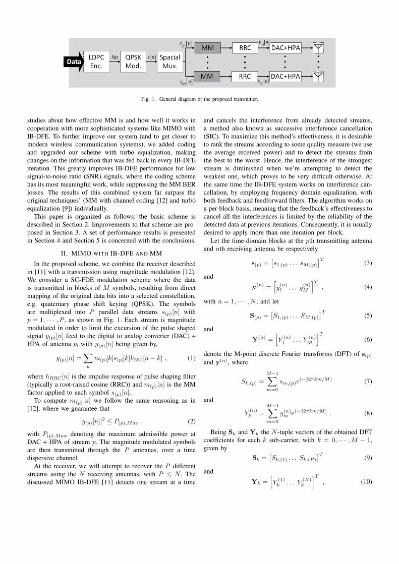
Fig. 1. General diagram of the proposed transmitter.
studies about how effective MM is and how well it works incooperation with more sophisticated systems like MIMO withIB-DFE. To further improve our system (and to get closer tomodern wireless communication systems), we added codingand upgraded our scheme with turbo equalization, makingchanges on the information that was fed back in every IB-DFEiteration. This greatly improves IB-DFE performance for lowsignal-to-noise ratio (SNR) signals, where the coding schemehas its most meaningful work, while suppressing the MM BERlosses. The results of this combined system far surpass theoriginal techniques’ (MM with channel coding [12] and turboequalization [9]) individually.
This paper is organized as follows: the basic scheme isdescribed in Section 2. Improvements to that scheme are pro-posed in Section 3. A set of performance results is presentedin Section 4 and Section 5 is concerned with the conclusions.
II. MIMO WITH IB-DFE AND MM
In the proposed scheme, we combine the receiver describedin [11] with a transmission using magnitude modulation [12].We consider a SC-FDE modulation scheme where the datais transmitted in blocks of M symbols, resulting from directmapping of the original data bits into a selected constellation,e.g. quaternary phase shift keying (QPSK). The symbolsare multiplexed into P parallel data streams s(p)[n] withp = 1, · · · , P , as shown in Fig. 1. Each stream is magnitudemodulated in order to limit the excursion of the pulse shapedsignal y(p)[n] feed to the digital to analog converter (DAC) +HPA of antenna p, with y(p)[n] being given by,
y(p)[n] =∑
k
m(p)[k]s(p)[k]hRRC[n− k] , (1)
where hRRC [n] is the impulse response of pulse shaping filter(typically a root-raised cosine (RRC)) and m(p)[n] is the MMfactor applied to each symbol s(p)[n].
To compute m(p)[n] we follow the same reasoning as in[12], where we guarantee that
|y(p)[n]|2 ≤ P(p),Max , (2)
with P(p),Max denoting the maximum admissible power atDAC + HPA of stream p. The magnitude modulated symbolsare then transmitted through the P antennas, over a timedispersive channel.
At the receiver, we will attempt to recover the P differentstreams using the N receiving antennas, with P ≤ N . Thediscussed MIMO IB-DFE [11] detects one stream at a time
and cancels the interference from already detected streams,a method also known as successive interference cancellation(SIC). To maximize this method’s effectiveness, it is desirableto rank the streams according to some quality measure (we usethe average received power) and to detect the streams fromthe best to the worst. Hence, the interference of the strongeststream is diminished when we’re attempting to detect theweakest one, which proves to be very difficult otherwise. Atthe same time the IB-DFE system works on interference can-cellation, by employing frequency domain equalization, withboth feedback and feedforward filters. The algorithm works ona per-block basis, meaning that the feedback’s effectiveness tocancel all the interferences is limited by the reliability of thedetected data at previous iterations. Consequently, it is usuallydesired to apply more than one iteration per block.
Let the time-domain blocks at the pth transmitting antennaand nth receiving antenna be respectively
s(p) =[s1,(p) . . . sM,(p)
]T(3)
and
y(n) =[y(n)1 . . . y
(n)M
]T, (4)
with n = 1, · · · , N , and let
S(p) =[S1,(p) . . . SM,(p)
]T(5)
and
Y(n) =[Y
(n)1 . . . Y
(n)M
]T(6)
denote the M-point discrete Fourier transforms (DFT) of s(p)and y(n), where
Sk,(p) =M−1∑
m=0
sm,(p)e(−j2πkm/M) (7)
and
Y(n)k =
M−1∑
m=0
y(n)m e(−j2πkm/M) . (8)
Being Sk and Yk the N -tuple vectors of the obtained DFTcoefficients for each k sub-carrier, with k = 0, · · · ,M − 1,given by
Sk =[Sk,(1) . . . Sk,(P )
]T(9)
and
Yk =[Y
(1)k . . . Y
(N)k
]T, (10)

the receiving frequency-domain signal Yk can be written as
Yk = HkSk + Nk , (11)
where, Hk and Nk represent respectively the frequency-domain dispersive channel and additive white gaussian noise(AWGN) matrices, written as
Hk =
H(1)k,(1) · · · H
(1)k,(P )
.... . .
...H
(N)k,(1) · · · H
(N)k,(P )
(12)
andNk =
[N
(1)k . . . N
(N)k
]T. (13)
The frequency-domain soft-estimations associated with thepth layer at the output of the equalizer are given by
Sk = FTkYk −BkS′k , (14)
where the feedforward and feedback matrices are respectively
Fk =
F(1)k,(1) · · · F
(1)k,(P )
.... . .
...F
(N)k,(1) · · · F
(N)k,(P )
(15)
and
Bk =
B(1)k,(1) · · · B
(1)k,(P )
.... . .
...B
(P )k,(1) · · · B
(P )k,(P )
. (16)
F(n)k,(p) and B
(p)k,(p) denote the feedforward and feedback
filters coefficients and the vector S′k contains the DFT ofthe time-domain blocks associated with latest estimations forthe transmitted symbols (for the first iteration those terms arezero).
The frequency-domain samples used in the feedback loopcan produce hard-estimations, Sk, which can be written as
Sk = PSk + ∆k , (17)
with the length-P column vector
∆k =[∆k,(1) . . . ∆k,(P )
]T, (18)
andP = diag(ρ(1), . . . , ρ(P )) . (19)
The correlation coefficients in (19) are given by
ρ(p) = E[Sk,(p)S∗k,(p)]/E[|Sk,(p)|2] = E[sm,(p)s
∗m,(p)]/ES ,
(20)where
ES = E[|sm,(p)|2] = E[|Sk,(p)|2]/M (21)
is the average symbol energy, common to all layers. SinceE[∆k,(p)S
∗k′,(p)] ≈ 0, we have
E[|∆k,(p)|2] ≈ (1− ρ2(p))MES . (22)
The correlation coefficient can be estimated from the time-domain samples associated with the equalizer output, sm,(p),as described in [17].
It can also be shown that time-domain samples associatedwith the equalizer output, sm, can be written as
sm = Γsm + Eeqm , (23)
where sm and sm denote the P size vectors with the time-domain signals and the time-domain equalizer’s soft outputs,respectively. The Eeqm and Γ matrices are given by
Eeqm =
[εeqm,(1) . . . ε
eqm,(P )
]T, (24)
where εeqm,(p) denotes the overall noise plus interference, and
Γ = diag(γ) , (25)
where
γ =1
M
M−1∑
k=0
[11×N (Hk � Fk)]T (26)
is a sized P column vector. The corresponding frequency-domain samples can be written as
Sk = ΓSk + EEqk , (27)
where the εEqk,(p) (k = 0, · · · ,M − 1) terms of the P -sizedvector EEqk are the DFT of εeqm,(p) (m = 0, · · · ,M − 1). Thesignal to interference plus noise ratio (SNIR) in the frequencydomain is written as
SNIRFk,(p) =|γ(p)|2MES[|εEqk,(p)|2
] . (28)
After combining (14), (28) and some algebraic manipula-tion, the optimum feedback coefficients that maximize (28) ata specific iteration are
Bk = P(FTkHk − Γ) . (29)
The feedforward coefficients, required by (29) and (26), areobtained from the following equation:
Fk = (I−P2)ΓHHk [(I−P2)HH
k Hk +P
SNRI]−1 , (30)
where the SNR at each receiving antenna is
SNR = (PES)/(2σ2N ) , (31)
being σ2N the variance of the real and imaginary parts of
the channel noise. Clearly, the feedforward and feedbackcoefficients take into account the reliability of each detectedblock through the corresponding correlation factor ρ(p). In thenext section we will explore this feature, using it to furtherimprove the system.

Fig. 2. Detection of the pth layer, for a given iteration in IB-DFE with turboequalization.
III. LDPC CODING AND TURBO EQUALIZATION
As mentioned in [12], MM has better results when channelcoding is used. The changes introduced in the time-domainsymbols are quite small and a decoder can easily correctmost errors, making this the first logical step to improve theproposed system.
When a MIMO IB-DFE is combined with coding/decoding,it is also called turbo equalization in the frequency domain [9].As the new data that is fed from a block’s equalization to thenext is the soft estimation of the current block symbols, we canuse LDPC coding [16] to obtain an improved estimation andto feed back that estimation instead. This turbo equalizationhas the double benefit of improving the block’s estimation ca-pacity (and therefore the correlation factor ρ(p), as previouslydiscussed) and to reduce the unpleasant part of MM, the BERpenalty.
For QPSK symbols with points {±1± j}, soft demappingand mapping is greatly simplified, becoming very easy todeploy. Defining the complex log likelihood ratio as
λm,(p) = λR,m,(p) + jλI,m,(q) , (32)
where λR,m,(q) (λI,m,(q)) is associated to Re[sm,(p)](Im[sm,(p)]), the soft demapper yields [18]
λm,(q) =4sm,(p)
σ2SD,(p)
, (33)
with σ2SD,(p) being the equalizer soft output variance. This
means that the log likelihood ratio is proportional to theequalizer soft output. In turn, if ηm,(p) = ηR,m,(p) + jηI,m,(p)is the complex log likelihood ratio at the decoder output(extrinsic information), we can further improve the equalizersoft output by making
sm,(p)) = tanh(ηR,m,(p)
2
)+ j tanh
(ηI,m,(p)2
). (34)
6 8 10 12 14 16 18 2010
−4
10−3
10−2
10−1
Eb/N
0[dB]
BE
R
Data Stream 1
Data Stream 2Data Stream 3
Data Stream 4
Iteration = 1Iteration = 2
Iteration = 4
Fig. 3. BER vs Eb/N0 performance of the uncoded IB-DFE with no MM,for different layers at different iterations.
6 8 10 12 14 16 18 2010
−4
10−3
10−2
10−1
Eb/N
0[dB]
BE
R
Data Stream 1
Data Stream 2Data Stream 3
Data Stream 4
Iteration = 1Iteration = 2
Iteration = 4
Fig. 4. BER vs Eb/N0 performance of the uncoded IB-DFE with MM, fordifferent layers at different iterations.
IV. PERFORMANCE RESULTS
In the following, we present a set of results obtained fromthe system’s simulation. For the sake of simplicity, we willassume that our system is under perfect synchronization andchannel estimation conditions.
In order to compare BER vs SNR performance of differentlayers at different iterations, we considered P = 4 layersand a receiver with N = 4 antennas. The layer’s indexesindicate the order they are detected. Each layer consists of 768QPSK data symbols, plus cyclic-extension. We considered thechannel model of [19], which has uncorrelated Rayleigh fadingat all frequencies (similar behaviors were observed for severetime-dispersive channels with rich multipath propagation). Alllayers are transmitted with the same amount of average powerand when MM is used, only 1 stage is applied, consideringthe use of a 0.2 roll-off RRC filter.
In Figs. 3 and 4, we simulate the basic system (withoutLDPC coding), with and without MM. On this configuration,for the same BER, MM requires 2 dB of extra SNR. From [12],the back-off reduction is about 4.4 dB and thus we conclude

3 3.5 4 4.5 5 5.5 6 6.5 710
−4
10−3
10−2
10−1
Eb/N
0[dB]
BE
R
Data Stream 1
Data Stream 2Data Stream 3
Data Stream 4
Iteration = 1Iteration = 2
Iteration = 4
Fig. 5. BER vs Eb/N0 performance of the IB-DFE with turbo equalizationand no MM, for different layers at different iterations.
3 3.5 4 4.5 5 5.5 6 6.5 710
−4
10−3
10−2
10−1
Eb/N
0[dB]
BE
R
Data Stream 1
Data Stream 2Data Stream 3
Data Stream 4
Iteration = 1Iteration = 2
Iteration = 4
Fig. 6. BER vs Eb/N0 performance of the IB-DFE with turbo equalizationand MM, for different layers at different iterations.
that the system has a net gain of 2.2 dBs.Applying a WiMAX (1536,768) LDPC code and reworking
our IB-DFE algorithm towards turbo equalization greatly im-proved our system, as shown in figures 5 and 6. Once again,it’s a comparison of the same system with and without MM.On this experiment and for the same BER, the MM onlyrequires about 0.25 dB of extra SNR, which combined withthe 4.4 dB gained from the HPA’s back-off yields a net gainof 4.1 dB.
V. CONCLUSIONS
In this paper, we applied a computational-wise effortlesssignal processing method (MM) on a MIMO system, a systemwith quite a high complexity. MM can be easily appliedto any currently working transmitter without any change inthe receiver, providing a significant enhancement in powerefficiency without interfering with the system’s main function.The results obtained showed that if the system already uses
coding, which always happens in modern communications, thenet gain is truly remarkable.
REFERENCES
[1] G. Li, Z. Xu, C. Xiong, C. Yang, S. Zhang, Y. Chen, and S. Xu, “Energy-efficient wireless communications: tutorial, survey, and open issues,”Wireless Communications, IEEE, vol. 18, no. 6, pp. 28–35, December2011.
[2] S. Zeadally, S. Khan, and N. Chilamkurti, “Energy-efficient networking:past, present, and future,” The Journal of Supercomputing, vol. 62, no. 3,pp. 1093–1118, 2012.
[3] G. Foschini and M. Gans, “On limits of wireless communications ina fading environment when using multiple antennas,” Wireless Pers.Commun., vol. 6, no. 3, pp. 311–335, March 1998.
[4] D. Gesbert, M. Shafi, D. shan Shiu, P. Smith, and A. Naguib, “Fromtheory to practice: an overview of mimo space-time coded wirelesssystems,” Selected Areas in Communications, IEEE Journal on, vol. 21,no. 3, pp. 281–302, Apr 2003.
[5] M. Di Renzo, H. Haas, A. Ghrayeb, S. Sugiura, and L. Hanzo,“Spatial modulation for generalized mimo: Challenges, opportunities,and implementation,” Proceedings of the IEEE, vol. 102, no. 1, pp. 56–103, Jan 2014.
[6] D. Falconer, S. Ariyavisitakul, A. Benyamin-Seeyar, and B. Eidson,“Frequency domain equalization for single-carrier broadband wirelesssystems,” Communications Magazine, IEEE, vol. 40, no. 4, pp. 58–66,Apr 2002.
[7] Y. Li, J. Cimini, L.J., and N. Sollenberger, “Robust channel estimationfor ofdm systems with rapid dispersive fading channels,” Communica-tions, IEEE Transactions on, vol. 46, no. 7, pp. 902–915, Jul. 1998.
[8] G. Quan, J. Yan-liang, S. Zhi-dong, and M. Hui-jun, “Papr analysisfor single-carrier fdma mimo systems with space-time/frequency blockcodes,” in Networks Security Wireless Communications and TrustedComputing (NSWCTC), 2010 Second International Conference on,vol. 2, April 2010, pp. 126–129.
[9] N. Benvenuto, R. Dinis, D. Falconer, and S. Tomasin, “Single carriermodulation with nonlinear frequency domain equalization: An ideawhose time has come again,” Proceedings of the IEEE, vol. 98, no. 1,pp. 69–96, jan. 2010.
[10] N. Benvenuto and S. Tomasin, “Block iterative dfe for single carriermodulation,” Electron. Lett., vol. 39, no. 19, pp. 1144–1145, September2002.
[11] R. Dinis, R. Kalbasi, D. Falconer, and A. Banihashemi, “Iterative layeredspace-time receivers for single-carrier transmission over severe time-dispersive channels,” IEEE Comm. Letters, vol. 39, no. 19, pp. 1144–1145, September 2004.
[12] M. Gomes, V. Silva, F. Cercas, and M. Tomlinson, “Power efficientback-off reduction through polyphase filtering magnitude modulation,”IEEE Commun. Lett., vol. 13, no. 8, pp. 606–608, August 2009.
[13] M. Gomes, R. Dinis, V. Silva, F. Cercas, and M. Tomlinson, “Errorrate analysis of m-psk with magnitude modulation envelope control,”Electronics Letters, vol. 49, no. 18, pp. 1184–1186, August 2013.
[14] M. Gomes, R. Dinis, V. Silva, F. Cercas, and M. Tomlinson, “Iterativefrequency domain equalization for single carrier signals with magnitudemodulation techniques,” in IEEE 76th Vehicular Technology Conference:VTC2012-Fall, Québec City, Canada, September 2012.
[15] M. Gomes, R. Dinis, V. Silva, F. Cercas, and M. Tomlinson, “Iterativefde design for ldpc-coded magnitude modulation schemes,” in WirelessCommunication Systems (ISWCS 2013), Proceedings of the Tenth Inter-national Symposium on, Aug 2013, pp. 1–5.
[16] S. Lin and J. D. J. Costello, Error Control Coding, 2nd ed. NJ: PearsonPrentice Hall, 2004.
[17] R. Dinis, A. Gusmão, and N. Esteves, “On broadband block transmissionover strongly frequency-selective fading channels,” in IEEE Wireless’03,Calgary, Canada, July 2003.
[18] N. Benvanuto and G. Cherubini, Algorithms for Communications Sys-tems and Their Applications. Chichester, U.K.: Wiley, 2002.
[19] A. Gusmão, R. Dinis, and N. Esteves, “On frequency-domain equal-ization and diversity combining for broadband communications,” IEEETrans. Commun., vol. 51, pp. 1029–1033, July 2003.

55