Embed Size (px)
Citation preview
JNCIAJuniper™ Networks Certified Internet Associate
Study Guide - Chapter 2
by Joseph M. Soricelliwith John L. Hammond, Galina Diker Pildush,Thomas E. Van Meter, and Todd M. Warble
This book was originally developed by Juniper Networks Inc. in conjunction with Sybex Inc. It is being offered in electronic format because the original book (ISBN: 0-7821-4071-8) is now out of print. Every effort has been made to remove the original publisher's name and references to the original bound book and its accompanying CD. The original paper book may still be available in used book stores or by contacting, John Wiley & Sons, Publishers. www.wiley.com.
Copyright © 2003-6 by Juniper Networks Inc. All rights reserved.
This publication may be used in assisting students to prepare for a Juniper JNCIA exam but Juniper Networks Inc. cannot warrant that use of this publication will ensure passing the relevant exam.
Chapter
2
Interfaces
JNCIA EXAM OBJECTIVES COVERED IN THIS CHAPTER:
�
Identify valid options for interface names and protocol
families within the JUNOS software
�
Describe the function of CLI commands used to monitor
interfaces
In this chapter, we present the basic skills required to configure and monitor interfaces on a Juniper Networks router. We compare per-manent and transient interfaces, and take a look at the JUNOS
software interface nomenclature. Next, we discuss the physical and logical properties of different interface types, focusing on the configuration of protocol families and virtual circuits.
Once the foundation has been laid, we explore several configuration examples of interfaces. The chapter concludes with a presentation of the JUNOS software command-line interface (CLI) commands used to monitor the status of interfaces, verify their operation, and perform troubleshooting.
Types of Interfaces
A Juniper Networks platform contains two types of interfaces. Permanent interfaces are always present in each router, while transient interfaces are inserted in or removed from the router by a user.
Permanent Interfaces
The
permanent interfaces
on a Juniper Networks platform perform two vital roles—management and operation. The management functionality is performed primarily by the
fxp0
interface. This
Management Ethernet
interface provides you with an out-of-band method for connecting to the router. This connection uses utilities such as Secure Shell (SSH) and Telnet to allow a remote user to manage and configure the router.
The
fxp0
interface on a Juniper Networks router does not provide forwarding capabilities for transit data packets. It is used only for user management con-
nectivity to the router.
The operation of a Juniper Networks platform itself relies on the
Internal Ethernet
inter-face,
fxp1
. The
fxp1
interface connects the Routing Engine to the Packet Forwarding Engine. This communications link is how routing protocol packets reach the Routing Engine to update
Interface Naming
63
the routing table. The forwarding table updates reach the Packet Forwarding Engine across this interface as well.
The Internal Ethernet interface is configured, addressed, and enabled automat-ically when the JUNOS software boots. There is never a reason to configure or disable the
fxp1
interface. Altering the default behavior can seriously impair
the router’s ability to perform its functions.
Transient Interfaces
When you talk about a router’s interfaces, you often mean the interfaces that receive a user’s data packet and then transmit that packet toward the final destination. For a Juniper Networks platform, these are
transient interfaces
. These interfaces are physically located on a
Physical Interface Card (PIC)
and can be inserted and removed from the router at any time. This prop-erty gives them their transient nature.
You must configure each transient interface before using it for operational purposes. In addi-tion, the JUNOS software allows you to configure transient interfaces that are not currently in the physical chassis. As the software activates the router’s configuration, it detects which inter-faces are actually present and activates only those transient interfaces. Should you install new physical interfaces in the router (for which some configuration exists), the JUNOS software activates the parameters for that transient interface.
You will learn how to configure transient interfaces in the “Interface Properties” section later in this chapter. Next, we discuss the naming structure for transient interfaces.
For the remainder of this book, any reference to the term
interface
should be interpreted as a transient interface. References to
fxp0
and
fxp1
as permanent
interfaces will be explicitly stated.
Interface Naming
In Chapter 1, “The Components of a Juniper Networks Router,” we saw that a router’s inter-faces are located on a PIC. The PIC is located on a particular
Flexible PIC Concentrator (FPC)
, which is inserted in a router’s chassis. This physical placement of interfaces becomes quite important when we start referencing them within the configuration. Each interface receives a unique name based on this location in the router. Let’s see how this works.
64
Chapter 2 �
Interfaces
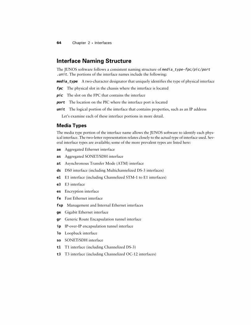
Interface Naming Structure
The JUNOS software follows a consistent naming structure of
media_type-fpc/pic/port.unit
. The portions of the interface names include the following:
media_type
A two-character designator that uniquely identifies the type of physical interface
fpc
The physical slot in the chassis where the interface is located
pic
The slot on the FPC that contains the interface
port
The location on the PIC where the interface port is located
unit
The logical portion of the interface that contains properties, such as an IP address
Let’s examine each of these interface portions in more detail.
Media Types
The media type portion of the interface name allows the JUNOS software to identify each phys-ical interface. The two-letter representation relates closely to the actual type of interface used. Sev-eral interface types are available; some of the more prevalent types are listed here:
ae
Aggregated Ethernet interface
as
Aggregated SONET/SDH interface
at
Asynchronous Transfer Mode (ATM) interface
ds
DS0 interface (including Multichannelized DS-3 interfaces)
e1
E1 interface (including Channelized STM-1 to E1 interfaces)
e3
E3 interface
es
Encryption interface
fe
Fast Ethernet interface
fxp
Management and Internal Ethernet interfaces
ge
Gigabit Ethernet interface
gr
Generic Route Encapsulation tunnel interface
ip
IP-over-IP encapsulation tunnel interface
lo
Loopback interface
so
SONET/SDH interface
t1
T1 interface (including Channelized DS-3)
t3
T3 interface (including Channelized OC-12 interfaces)
Interface Naming
65
The
fxp
interfaces are the only current interface types that do not follow the two-letter designator format. These interfaces are special in their function, and this uniqueness is represented in their media type descriptor. The “Permanent Interfaces” section earlier in this chapter describes the
fxp
interfaces in more
detail.
FPC Slot Numbers
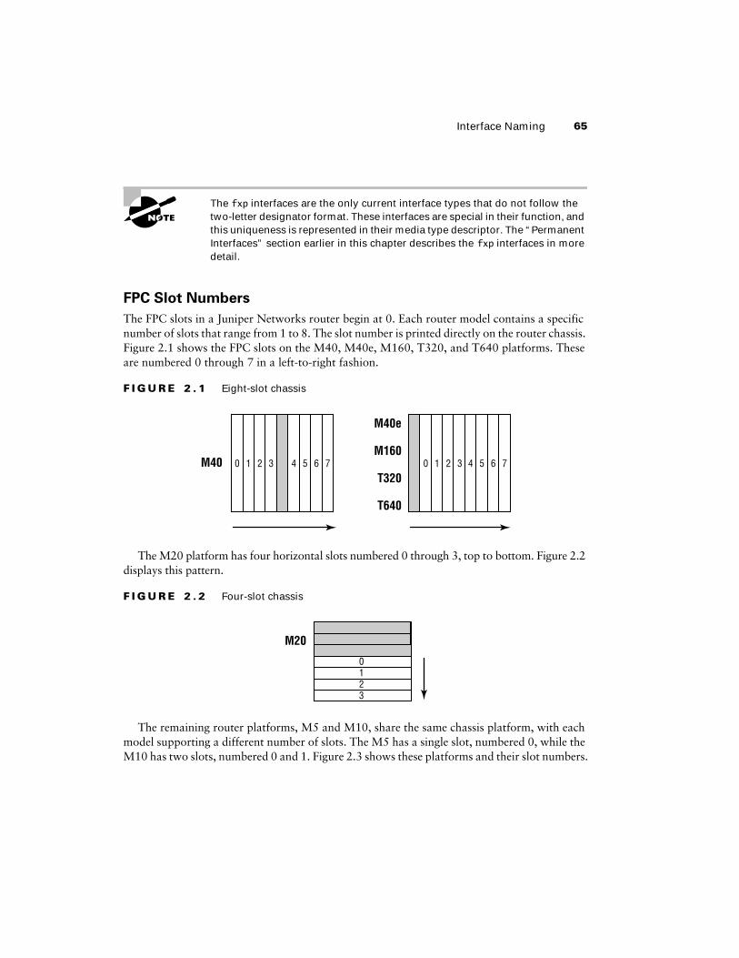
The FPC slots in a Juniper Networks router begin at 0. Each router model contains a specific number of slots that range from 1 to 8. The slot number is printed directly on the router chassis. Figure 2.1 shows the FPC slots on the M40, M40e, M160, T320, and T640 platforms. These are numbered 0 through 7 in a left-to-right fashion.
F I G U R E 2 . 1
Eight-slot chassis
The M20 platform has four horizontal slots numbered 0 through 3, top to bottom. Figure 2.2 displays this pattern.
F I G U R E 2 . 2
Four-slot chassis
The remaining router platforms, M5 and M10, share the same chassis platform, with each model supporting a different number of slots. The M5 has a single slot, numbered 0, while the M10 has two slots, numbered 0 and 1. Figure 2.3 shows these platforms and their slot numbers.
M40 0 1 2 3 4 5 6 7 0 1 2 3 4 5 6 7M160
T640
M40e
T320
3210
M20
66
Chapter 2 �
Interfaces
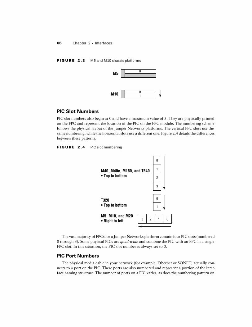
F I G U R E 2 . 3
M5 and M10 chassis platforms
PIC Slot Numbers
PIC slot numbers also begin at 0 and have a maximum value of 3. They are physically printed on the FPC and represent the location of the PIC on the FPC module. The numbering scheme follows the physical layout of the Juniper Networks platforms. The vertical FPC slots use the same numbering, while the horizontal slots use a different one. Figure 2.4 details the differences between these patterns.
F I G U R E 2 . 4
PIC slot numbering
The vast majority of FPCs for a Juniper Networks platform contain four PIC slots (numbered 0 through 3). Some physical PICs are
quad-wide
and combine the PIC with an FPC in a single FPC slot. In this situation, the PIC slot number is always set to 0.
PIC Port Numbers
The physical media cable in your network (for example, Ethernet or SONET) actually con-nects to a port on the PIC. These ports are also numbered and represent a portion of the inter-face naming structure. The number of ports on a PIC varies, as does the numbering pattern on
10M10
M5 0
0
1
3
2
013 2
M40, M40e, M160, and T640• Top to bottom
M5, M10, and M20• Right to left
0
1
T320• Top to bottom
Interface Naming
67
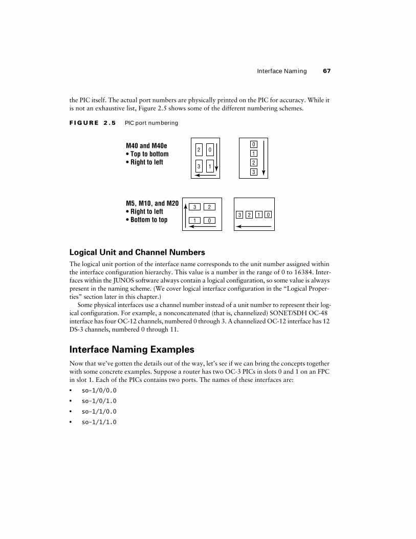
the PIC itself. The actual port numbers are physically printed on the PIC for accuracy. While it is not an exhaustive list, Figure 2.5 shows some of the different numbering schemes.
F I G U R E 2 . 5
PIC port numbering
Logical Unit and Channel Numbers
The logical unit portion of the interface name corresponds to the unit number assigned within the interface configuration hierarchy. This value is a number in the range of 0 to 16384. Inter-faces within the JUNOS software always contain a logical configuration, so some value is always present in the naming scheme. (We cover logical interface configuration in the “Logical Proper-ties” section later in this chapter.)
Some physical interfaces use a channel number instead of a unit number to represent their log-ical configuration. For example, a nonconcatenated (that is, channelized) SONET/SDH OC-48 interface has four OC-12 channels, numbered 0 through 3. A channelized OC-12 interface has 12 DS-3 channels, numbered 0 through 11.
Interface Naming Examples
Now that we’ve gotten the details out of the way, let’s see if we can bring the concepts together with some concrete examples. Suppose a router has two OC-3 PICs in slots 0 and 1 on an FPC in slot 1. Each of the PICs contains two ports. The names of these interfaces are:�
so-1/0/0.0
�
so-1/0/1.0
�
so-1/1/0.0
�
so-1/1/1.0
0
1
2
3
M40 and M40e• Top to bottom• Right to left
M5, M10, and M20• Right to left• Bottom to top 01
230123
0
1
2
3
68
Chapter 2 �
Interfaces
When an FPC in slot 3 contains four OC-12 ATM PICs, the FPC becomes fully populated. Each PIC supports a single physical port. The interface names when each port has a single log-ical unit assigned are:� at-3/0/0.0
� at-3/1/0.0
� at-3/2/0.0
� at-3/3/0.0
The OC-48 SONET FPC in an M40 router is an example of a quad-wide PIC. Should this PIC be installed in slot 6, it appears as PIC slot 0 with a single port 0. The JUNOS software rep-resentation becomes:
so-6/0/0.0
A channelized OC-12 PIC contains 12 logical DS-3 channels. When installed in PIC slot 2 on FPC slot 2, the channels are represented as:� t3-2/2/0:0
� t3-2/2/0:1
� t3-2/2/0:2
� t3-2/2/0:3
� t3-2/2/0:4
� t3-2/2/0:5
� t3-2/2/0:6
� t3-2/2/0:7
� t3-2/2/0:8
� t3-2/2/0:9
� t3-2/2/0:10
� t3-2/2/0:11
Interface PropertiesInterfaces in the JUNOS software contain both physical and logical properties. The actual media type (such as Ethernet or SONET) often determines the physical properties of the interface. An interface’s logical properties represent the Layer 3 routing and Layer 2 transmission parameters needed to operate the interface in a network. Let’s examine the physical properties first.
Physical Properties
Each interface in the router inherits certain default values for its physical properties. When the JUNOS software activates an interface, it assigns these values. The list of possible physical options
Interface Properties 69
and changes is exhausting, but a few values are more commonly used than others. These proper-ties include the following:
Description A user-defined text description is available for all interfaces. This is often used to describe the interface’s purpose.
Diagnostic characteristics Circuit-testing capabilities, such as loopback settings or Bit Error Rate Test (BERT) tests, are user-configured on a per-physical interface basis. (We discuss these tools in the “Useful Interface Commands” section later in this chapter.)
Encapsulation Options for encapsulation types vary for different media types.
Frame check sequence (FCS) This field is used for error-checking received packets. You can change the default value from a 16-bit field to a 32-bit mode.
Interface clock source Point-to-point interfaces require a clocking source for synchronization purposes. Options here include internal (the default) or external.
Interface MTU size The maximum transmission unit (MTU) of the physical interface can be changed. Each interface has a different default value; the possible range is 256 to 9192 bytes.
Keepalives A keepalive is a physical-layer mechanism that is used to determine whether the interface is operating correctly. With the exception of ATM interfaces, each interface uses keepalives by default. You can disable this function.
Payload scrambling Scrambling is a mechanism used for long-haul communications to assist in an error-free transmission. Most interfaces in the JUNOS software use a default value of payload-scrambler, but you can disable this function as well.
Connecting to Another Vendor’s Router
When two Juniper Networks routers are connected, the default physical properties allow the network link to operate normally. However, the physical interface defaults do not always match the operational parameters of another vendor. In situations like this, you must change the oper-ation of one side of the link to allow the connection to fully function.
One good example of this is connecting a SONET point-to-point link to a router from Cisco Sys-tems. The default encapsulation type for a SONET link within the JUNOS software is the Point-to-Point Protocol (PPP). A Cisco Systems router, on the other hand, uses a Cisco proprietary for-mat of the High-Level Data Link Control (HDLC) protocol. The JUNOS software supports this HDLC format on point-to-point interfaces using the keyword cisco-hdlc. Once configured, your Juniper Networks router and Cisco Systems router can interoperate and pass user data traffic.
70 Chapter 2 � Interfaces
Logical Properties
Each and every interface within the JUNOS software requires at least one logical interface, called a unit. This is where all addressing and protocol information is configured. Some physical encapsulations allow only a single logical unit. PPP and Cisco-HDLC fall into this category. Logical interfaces, such as the loopback, and non-VLAN Ethernet also provide for only one log-ical unit. In both situations, the logical interface is assigned a unit value of 0.
Multiple logical interface units are often used in ATM, Frame Relay, and VLAN tagged Ether-net networks. In these cases, each logical unit is assigned a Virtual Circuit Identifier (VCI), Data-Link Connection Identifier (DLCI), or Virtual Local Area Network (VLAN) number, respectively. This system allows you to map multiple logical interfaces onto a single physical interface. The JUNOS software views each logical interface as a separate entity.
Common logical interface properties include a protocol family, logical Layer 3 addressing, MTU, and virtual circuit (Layer 2) addressing information.
Protocol Families
Each logical interface in the JUNOS software has the ability to support one or more protocol families. These families enable the logical interface to accept and process data packets for the router. Without their configuration, the interface drops any unknown transmissions. Currently four possible protocol families are available for your use:
inet The inet protocol family supports IP version 4 (IPv4) packets.
inet6 To allow support for IP version 6 (IPv6) data packets, each interface can be configured with the inet6 protocol family.
iso The Intermediate System to Intermediate System (IS-IS) routing protocol uses a data link encapsulation defined by the International Standards Organization (ISO). The iso protocol family allows the processing of these packet types. (IS-IS is discussed in greater detail in Chapter 7.)
mpls The mpls protocol family provides support for processing packets encoded with a Multi-protocol Label Switching (MPLS) label. This label information allows the router to forward the data packet. (We discuss MPLS in greater detail in Chapter 11.)
Protocol Addresses
A protocol address is a logical Layer 3 value used to route user packets in a network. For example, an IPv4 address of 192.168.1.1 /24 is a protocol address. The JUNOS software allows addressing for the inet, inet6, and iso protocol families. The inet family provides the capability to assign multiple addresses to each logical unit, with each address equally represented on the interface. In this situation, you encounter the concepts of the primary address and the preferred address.
A single primary address is assigned to each interface. By default, it is the lowest numerical IP address configured. For example, 10.10.10.1 /24 is a lower value than 172.16.1.1 /24. The primary address is used as the source address of a packet when the destination address is not local to a configured subnet. Let’s look at an example.
Cabernet has both 10.10.10.1 /24 and 172.16.1.1 /24 configured on its fe-0/0/0.0 interface. You use the ping command to form an IPv4 packet with a destination address of 192.168.100.10.
Interface Properties 71
This packet is ready for transmission on the fe-0/0/0.0 interface. Since the destination address is not part of the interface’s subnets, the primary interface address of 10.10.10.1 is used as the source IP address within the packet.
Unlike the primary address, a logical unit may have multiple preferred addresses at the same time. The preferred address is used when an interface has two addresses configured within the same subnet. The default selection of the preferred address is similar to the primary address in that the lowest numerical prefix is selected. The use of the preferred address is also similar in that it assists the interface in selecting the source IP address of a packet.
We’ve added the 172.16.1.100 /24 address to Cabernet’s fe-0/0/0.0 interface. This time, we issue the ping command to the destination of 172.16.1.200. The outgoing subnet is known to the interface, so the primary address is not automatically used. The local address within the subnet is used instead, but in our case we have two addresses configured in the subnet. The pre-ferred address of 172.16.1.1 is used in this case as the source IP address.
You will find examples of defining different protocol families, protocol addresses, and altering the primary and preferred addresses in the “Configuration Examples” section later in this chapter.
Protocol MTU
An MTU value can be configured for each logical unit in the router. The default values vary for each physical media type as well as for the protocol family configured.
Multiple Addresses on an Interface
The discussion on primary and preferred addresses for an interface brings up an interesting point. The JUNOS software allows multiple IP addresses on a logical unit. A Cisco Systems inter-face allows multiple IP addresses by using a concept called a secondary address. In this case, only the primary address is used for all interface functions. A Juniper Networks router, on the other hand, sees no functional difference between the addresses on its interfaces. All addresses are equal to the operating system. Each address forms routing protocol neighbor relationships, and each is advertised into the Interior Gateway Protocol (IGP).
This default behavior means that you must take care when changing IP addresses on an interface. Simply configuring the new address results in multiple addresses assigned to the interface. You have two main methods for avoiding this issue. First, you can remove the old address by using the delete command prior to configuring the new address. Second, you can change the old address to the new address by using the rename command.
The use of rename is covered in Chapter 4, “Routing Policy.” In addition, Chapter 4 contains a sidebar titled “Other Uses for rename.”
72 Chapter 2 � Interfaces
Point-to-point interfaces When you’re using an encapsulation type of PPP, Cisco-HDLC, ATM, or Frame Relay, the default MTU for the inet and iso protocols is 4470 bytes. The mpls protocol family uses a value of 4458 bytes.
Broadcast interfaces Both a Gigabit Ethernet and a Fast Ethernet interface share the same properties for protocol MTU sizes. The inet family uses 1500 bytes, the iso family uses 1497 bytes, and the mpls family uses 1488 bytes.
The difference between the protocol MTU and the interface MTU discussed in the “Physical Properties” section earlier in this chapter is quite important. The interface MTU is the largest size packet able to be sent on the physical media. This value includes all Layer 2 overhead information, such as the destination MAC address on Ethernet, or the labels in an MPLS environment. The Cyclic Redundancy Check (CRC) information is not included in this value, however. Each encapsulation type has a payload field where higher-layer information is stored. This payload field is the size of the protocol MTU. This is the largest amount of logical protocol data, including the protocol header, able to be sent on a particular interface.
Virtual Circuit Addressing
An interface configured for use on an ATM, Frame Relay, or Ethernet VLAN network requires the addition of a Layer 2 virtual circuit address. We examine these options next.
ATM VPI and VCI
An Asynchronous Transfer Mode (ATM) network uses the concept of a virtual path and a virtual circuit to connect two devices. The path is represented by a virtual path identifier (VPI), which can be thought of as a logical conduit between the devices. Each VPI in a network may contain mul-tiple logical circuits represented by a virtual circuit identifier (VCI), which is the actual connection between the devices.
Each logical unit in the router is assigned a VPI/VCI Layer 2 address. The path values range from 0 to 255, while the circuits on that path can be between 0 and 4089. These values are locally significant so that the two connected devices agree on their usage. The specific pair can then be used elsewhere in the ATM network, allowing for greater overall scalability.
As an example, assume that the Merlot router is connected to Riesling through an ATM interface. Ten logical units are created on the interface, each with a unique IPv4 address and VCI value. When data packets are passed between the two routers, the VCI address at Layer 2 helps determine which logical unit should receive and process the packet.
Frame Relay DLCI
In a manner similar to ATM, a Frame Relay network uses data link connection identifiers (DLCIs) to address packets at Layer 2. The DLCI value is the logical circuit between the two devices, which is also locally significant. Each logical interface unit assigned a DLCI becomes a Frame Relay per-
Interface Properties 73
manent virtual circuit (PVC). Possible DLCI values range between 1 and 1022 with reserved ranges between 1 and 15 and between1008 and 1022.
Suppose that the routers Cabernet and Shiraz are communicating over a Frame Relay net-work. The logical circuit that connects them is assigned a DLCI value of 200 on each router. The DLCI provides enough addressing for a data packet to reach the other router and for the receiv-ing router to process it with the appropriate logical unit.
Ethernet VLAN Tags
For broadcast-capable media, such as Fast Ethernet and Gigabit Ethernet, the JUNOS soft-ware supports a subset of the IEEE 802.1Q standard for channelizing an interface into mul-tiple logical interfaces. These channels are referred to as virtual local area networks (VLANs). A VLAN allows many hosts to connect to an Ethernet switch while maintaining separate log-ical subnets and broadcast domains. Each Ethernet interface on a Juniper Networks router can support up to 1024 VLANs. Gigabit and some Fast Ethernet interfaces use values in the range of 0 to 4094, while the rest of the Ethernet interfaces use values between 0 and 1023.
The operation of a VLAN is similar to the Layer 2 operation of ATM and Frame Relay. Two routers share a VLAN value, allowing data packets to be processed by the correct logical interface.
Disabling or Deactivating an Interface
Interfaces within the JUNOS software are automatically enabled for operation when config-ured in the router. To stop the operation of a particular interface, you may use one of two CLI commands—disable or deactivate. Both halt an interface without removing the current con-figuration in the router. This allows you to easily restart the interface when needed.
The difference between the commands is how the JUNOS software uses the configuration when the commit command is issued. Using the disable command at the [edit interfaces interface-name] hierarchy level allows the router to use the interface configuration. Opera-tionally, the interface is viewed as down, or administratively disabled.
The deactivate command places an inactive tag next to the configuration in the router. As the commit command is issued, the JUNOS software completely ignores the configuration. Operationally, the interface has no configuration—as if you had never entered any commands at all.
Examples of using these commands are provided in the next section. In addition, we’ll explore the configuration of protocol families and addresses.
The JUNOS software provides several methods to move the configuration of an interface to a new location. The rename and insert commands discussed in Chapter 1 are available. In addition, you can use the deactivate command to remove all knowledge of an interface’s configuration. This is critical in a situa-tion where duplicate IP addresses are used.
74 Chapter 2 � Interfaces
Configuration ExamplesIn this section, we’ll discuss the commands required to perform some basic interface configur-ation. As a framework for our discussion, we’ll examine how to configure each of the protocol families (inet, inet6, iso, mpls) to the router’s interfaces. These basic examples allow you to get a feel for how the JUNOS software interacts with its transient interfaces.
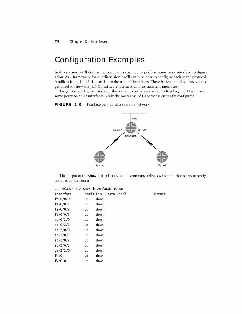
To get started, Figure 2.6 shows the router Cabernet connected to Riesling and Merlot over some point-to-point interfaces. Only the hostname of Cabernet is currently configured.
F I G U R E 2 . 6 Interface configuration sample network
The output of the show interfaces terse command tells us which interfaces are currently installed in the router:
user@Cabernet> show interfaces terse
Interface Admin Link Proto Local Remote
fe-0/0/0 up down
fe-0/0/1 up down
fe-0/0/2 up down
fe-0/0/3 up down
at-0/2/0 up down
at-0/2/1 up down
so-2/0/0 up down
so-2/0/1 up down
so-2/0/2 up down
so-2/0/3 up down
ge-2/2/0 up down
fxp0 up down
fxp0.0 up down
so-2/0/0 at-0/2/0
fxp0
Cabernet
Riesling Merlot
Configuration Examples 75
fxp1 up up
fxp1.0 up up tnp 4
gre up up
ipip up up
lo0 up up
lsi up up
mtun up up
pimd up up
pime up up
tap up up
Interfaces are always displayed in numerical order, from the lowest to the highest FPC slot number. Within that slot, the lowest PIC slot is shown first, and on an individual PIC the lowest port number is always first.
All interface configurations are completed at the [edit interfaces] hierarchy level. A generic interface configuration looks like this:
interfaces {
interface-name {
physical-properties;
unit unit-number {
logical-properties;
}
}
}
IP Version 4
We’ll start building our network by configuring some interfaces with the inet protocol fam-ily and IPv4 addresses. We’ll have an Ethernet broadcast interface, an ATM, and a SONET interface.
Broadcast Interfaces
The out-of-band management interface of fxp0 is first:
[edit interfaces fxp0]
user@Cabernet# set unit 0 family inet address 172.16.0.1/24
user@Cabernet# set description "This is the Ethernet management interface"
Notice that the logical IP address is configured within the family inet hierarchy directory and that the prefix length of the address is used, not the address mask. The prefix length is the number of bits in the network portion of the IP address. For example, a prefix length of /24
76 Chapter 2 � Interfaces
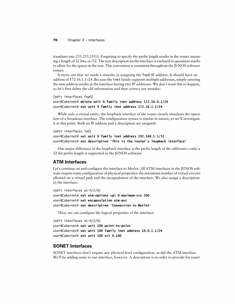
translates into 255.255.255.0. Forgetting to specify the prefix length results in the router assum-ing a length of 32 bits, or /32. The text description on the interface is enclosed in quotation marks to allow for the spaces in the text. This convention is consistent throughout the JUNOS software syntax.
It turns out that we made a mistake in assigning the fxp0 IP address. It should have an address of 172.16.1.1 /24. Because the inet family supports multiple addresses, simply entering the new address results in the interface having two IP addresses. We don’t want this to happen, so let’s first delete the old information and then correct our mistake:
[edit interfaces fxp0]
user@Cabernet# delete unit 0 family inet address 172.16.0.1/24
user@Cabernet# set unit 0 family inet address 172.16.1.1/24
While only a virtual entity, the loopback interface of the router closely simulates the opera-tion of a broadcast interface. The configuration syntax is similar in nature, so we’ll investigate it at this point. Both an IP address and a description are assigned:
[edit interfaces lo0]
user@Cabernet# set unit 0 family inet address 192.168.1.1/32
user@Cabernet# set description "This is the router's loopback interface"
One major difference of the loopback interface is the prefix length of the addresses—only a 32-bit prefix length is supported in the JUNOS software.
ATM Interfaces
Let’s continue on and configure the interface to Merlot. All ATM interfaces in the JUNOS soft-ware require some configuration of physical properties: the maximum number of virtual circuits allowed on a virtual path and the encapsulation of the interface. We also assign a description to the interface:
[edit interfaces at-0/2/0]
user@Cabernet# set atm-options vpi 0 maximum-vcs 200
user@Cabernet# set encapsulation atm-pvc
user@Cabernet# set description "Connection to Merlot"
Then, we can configure the logical properties of the interface:
[edit interfaces at-0/2/0]
user@Cabernet# set unit 100 point-to-point
user@Cabernet# set unit 100 family inet address 10.0.1.1/24
user@Cabernet# set unit 100 vci 0.100
SONET Interfaces
SONET interfaces don’t require any physical-level configuration, as did the ATM interface. We’ll be adding some to our interface, however. A description is in order to provide for easier
Configuration Examples 77
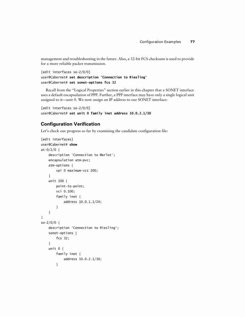
management and troubleshooting in the future. Also, a 32-bit FCS checksum is used to provide for a more reliable packet transmission.
[edit interfaces so-2/0/0]
user@Cabernet# set description "Connection to Riesling"
user@Cabernet# set sonet-options fcs 32
Recall from the “Logical Properties” section earlier in this chapter that a SONET interface uses a default encapsulation of PPP. Further, a PPP interface may have only a single logical unit assigned to it—unit 0. We now assign an IP address to our SONET interface:
[edit interfaces so-2/0/0]
user@Cabernet# set unit 0 family inet address 10.0.2.1/30
Configuration Verification
Let’s check our progress so far by examining the candidate configuration file:
[edit interfaces]
user@Cabernet# show
at-0/2/0 {
description "Connection to Merlot";
encapsulation atm-pvc;
atm-options {
vpi 0 maximum-vcs 200;
}
unit 100 {
point-to-point;
vci 0.100;
family inet {
address 10.0.1.1/24;
}
}
}
so-2/0/0 {
description "Connection to Riesling";
sonet-options {
fcs 32;
}
unit 0 {
family inet {
address 10.0.2.1/30;
}
78 Chapter 2 � Interfaces
}
}
fxp0 {
description "This is the Ethernet management interface";
unit 0 {
family inet {
address 172.16.1.1/24;
}
}
}
lo0 {
description "This is the router's loopback interface";
unit 0 {
family inet {
address 192.168.1.1/32;
}
}
}
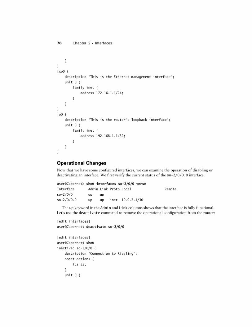
Operational Changes
Now that we have some configured interfaces, we can examine the operation of disabling or deactivating an interface. We first verify the current status of the so-2/0/0.0 interface:
user@Cabernet> show interfaces so-2/0/0 terse
Interface Admin Link Proto Local Remote
so-2/0/0 up up
so-2/0/0.0 up up inet 10.0.2.1/30
The up keyword in the Admin and Link columns shows that the interface is fully functional. Let’s use the deactivate command to remove the operational configuration from the router:
[edit interfaces]
user@Cabernet# deactivate so-2/0/0
[edit interfaces]
user@Cabernet# show
inactive: so-2/0/0 {
description "Connection to Riesling";
sonet-options {
fcs 32;
}
unit 0 {
Configuration Examples 79
family inet {
address 10.0.2.1/30;
}
}
}
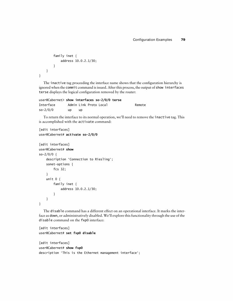
The inactive tag proceeding the interface name shows that the configuration hierarchy is ignored when the commit command is issued. After this process, the output of show interfaces terse displays the logical configuration removed by the router:
user@Cabernet> show interfaces so-2/0/0 terse
Interface Admin Link Proto Local Remote
so-2/0/0 up up
To return the interface to its normal operation, we’ll need to remove the inactive tag. This is accomplished with the activate command:
[edit interfaces]
user@Cabernet# activate so-2/0/0
[edit interfaces]
user@Cabernet# show
so-2/0/0 {
description "Connection to Riesling";
sonet-options {
fcs 32;
}
unit 0 {
family inet {
address 10.0.2.1/30;
}
}
}
The disable command has a different effect on an operational interface. It marks the inter-face as down, or administratively disabled. We’ll explore this functionality through the use of the disable command on the fxp0 interface:
[edit interfaces]
user@Cabernet# set fxp0 disable
[edit interfaces]
user@Cabernet# show fxp0
description "This is the Ethernet management interface";
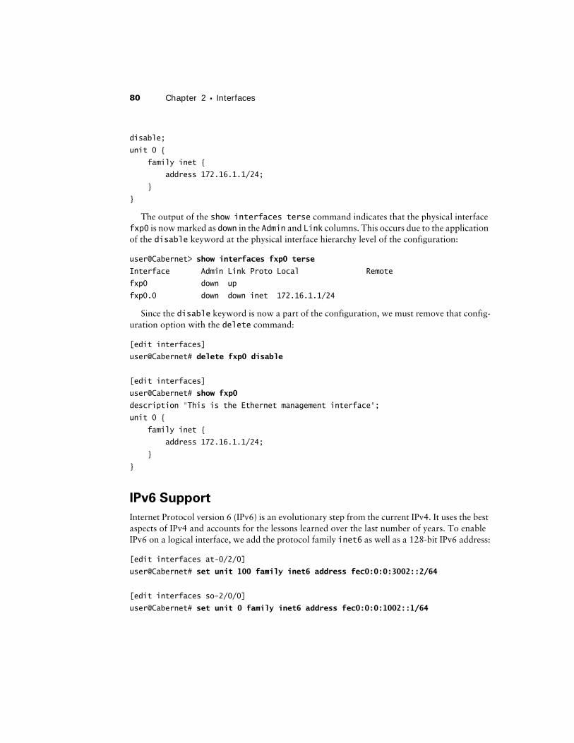
80 Chapter 2 � Interfaces
disable;
unit 0 {
family inet {
address 172.16.1.1/24;
}
}
The output of the show interfaces terse command indicates that the physical interface fxp0 is now marked as down in the Admin and Link columns. This occurs due to the application of the disable keyword at the physical interface hierarchy level of the configuration:
user@Cabernet> show interfaces fxp0 terse
Interface Admin Link Proto Local Remote
fxp0 down up
fxp0.0 down down inet 172.16.1.1/24
Since the disable keyword is now a part of the configuration, we must remove that config-uration option with the delete command:
[edit interfaces]
user@Cabernet# delete fxp0 disable
[edit interfaces]
user@Cabernet# show fxp0
description "This is the Ethernet management interface";
unit 0 {
family inet {
address 172.16.1.1/24;
}
}
IPv6 Support
Internet Protocol version 6 (IPv6) is an evolutionary step from the current IPv4. It uses the best aspects of IPv4 and accounts for the lessons learned over the last number of years. To enable IPv6 on a logical interface, we add the protocol family inet6 as well as a 128-bit IPv6 address:
[edit interfaces at-0/2/0]
user@Cabernet# set unit 100 family inet6 address fec0:0:0:3002::2/64
[edit interfaces so-2/0/0]
user@Cabernet# set unit 0 family inet6 address fec0:0:0:1002::1/64
Configuration Examples 81
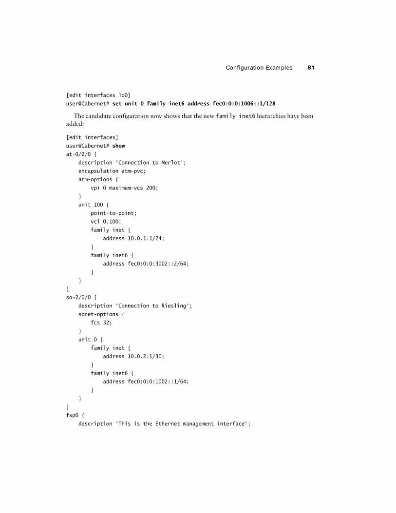
[edit interfaces lo0]
user@Cabernet# set unit 0 family inet6 address fec0:0:0:1006::1/128
The candidate configuration now shows that the new family inet6 hierarchies have been added:
[edit interfaces]
user@Cabernet# show
at-0/2/0 {
description "Connection to Merlot";
encapsulation atm-pvc;
atm-options {
vpi 0 maximum-vcs 200;
}
unit 100 {
point-to-point;
vci 0.100;
family inet {
address 10.0.1.1/24;
}
family inet6 {
address fec0:0:0:3002::2/64;
}
}
}
so-2/0/0 {
description "Connection to Riesling";
sonet-options {
fcs 32;
}
unit 0 {
family inet {
address 10.0.2.1/30;
}
family inet6 {
address fec0:0:0:1002::1/64;
}
}
}
fxp0 {
description "This is the Ethernet management interface";
82 Chapter 2 � Interfaces
unit 0 {
family inet {
address 172.16.1.1/24;
}
}
}
lo0 {
description "This is the router's loopback interface";
unit 0 {
family inet {
address 192.168.1.1/32;
}
family inet6 {
address fec0:0:0:1006::1/128;
}
}
}
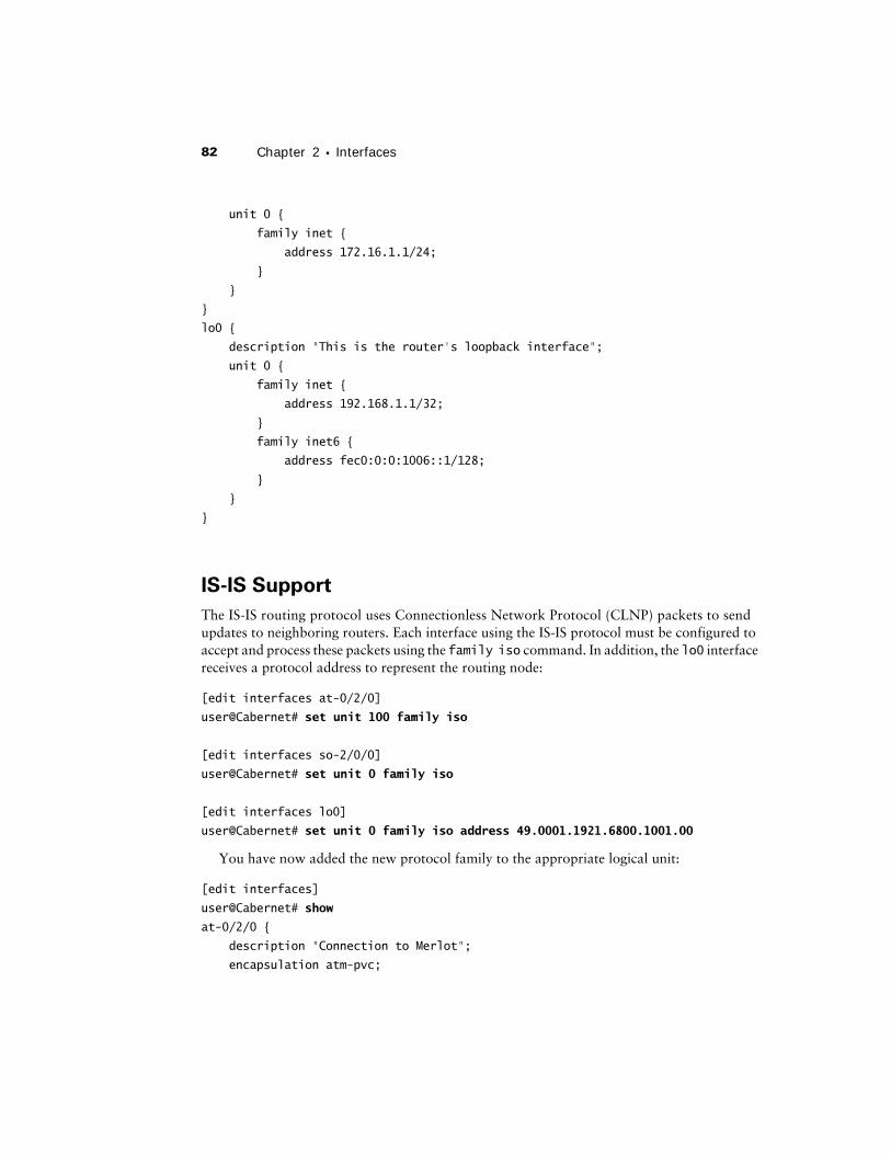
IS-IS Support
The IS-IS routing protocol uses Connectionless Network Protocol (CLNP) packets to send updates to neighboring routers. Each interface using the IS-IS protocol must be configured to accept and process these packets using the family iso command. In addition, the lo0 interface receives a protocol address to represent the routing node:
[edit interfaces at-0/2/0]
user@Cabernet# set unit 100 family iso
[edit interfaces so-2/0/0]
user@Cabernet# set unit 0 family iso
[edit interfaces lo0]
user@Cabernet# set unit 0 family iso address 49.0001.1921.6800.1001.00
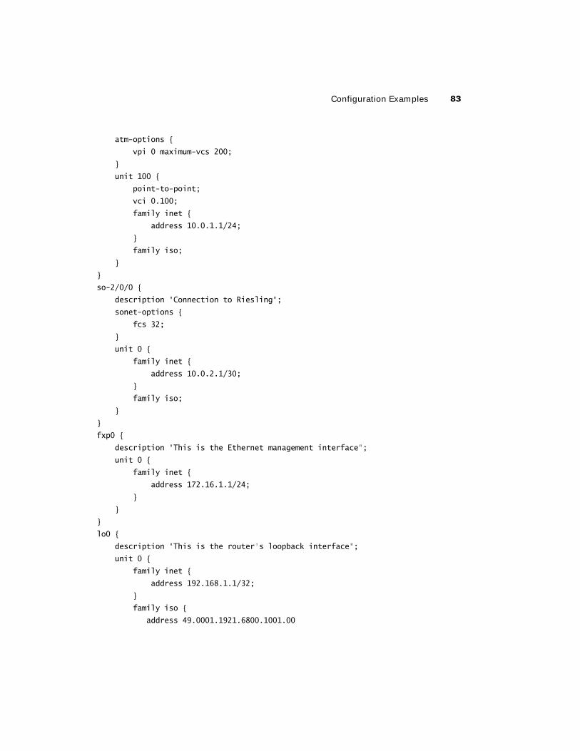
You have now added the new protocol family to the appropriate logical unit:
[edit interfaces]
user@Cabernet# show
at-0/2/0 {
description "Connection to Merlot";
encapsulation atm-pvc;
Configuration Examples 83
atm-options {
vpi 0 maximum-vcs 200;
}
unit 100 {
point-to-point;
vci 0.100;
family inet {
address 10.0.1.1/24;
}
family iso;
}
}
so-2/0/0 {
description "Connection to Riesling";
sonet-options {
fcs 32;
}
unit 0 {
family inet {
address 10.0.2.1/30;
}
family iso;
}
}
fxp0 {
description "This is the Ethernet management interface";
unit 0 {
family inet {
address 172.16.1.1/24;
}
}
}
lo0 {
description "This is the router's loopback interface";
unit 0 {
family inet {
address 192.168.1.1/32;
}
family iso {
address 49.0001.1921.6800.1001.00
84 Chapter 2 � Interfaces
}
}
}
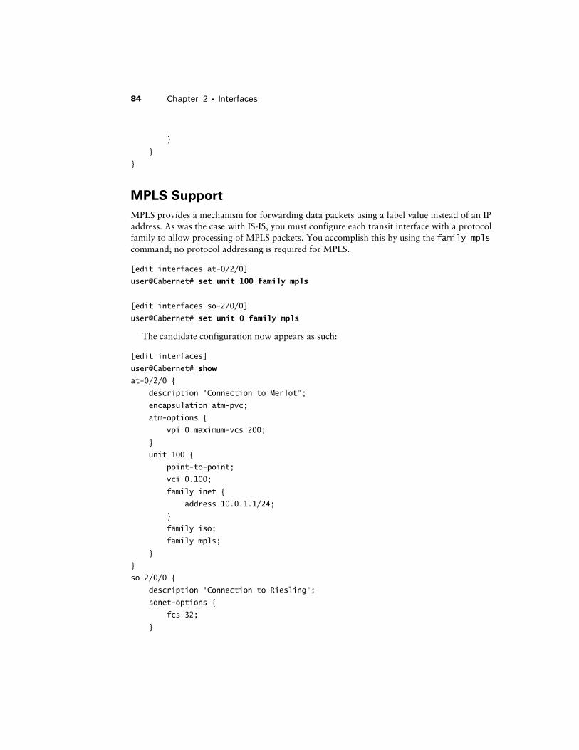
MPLS Support
MPLS provides a mechanism for forwarding data packets using a label value instead of an IP address. As was the case with IS-IS, you must configure each transit interface with a protocol family to allow processing of MPLS packets. You accomplish this by using the family mpls command; no protocol addressing is required for MPLS.
[edit interfaces at-0/2/0]
user@Cabernet# set unit 100 family mpls
[edit interfaces so-2/0/0]
user@Cabernet# set unit 0 family mpls
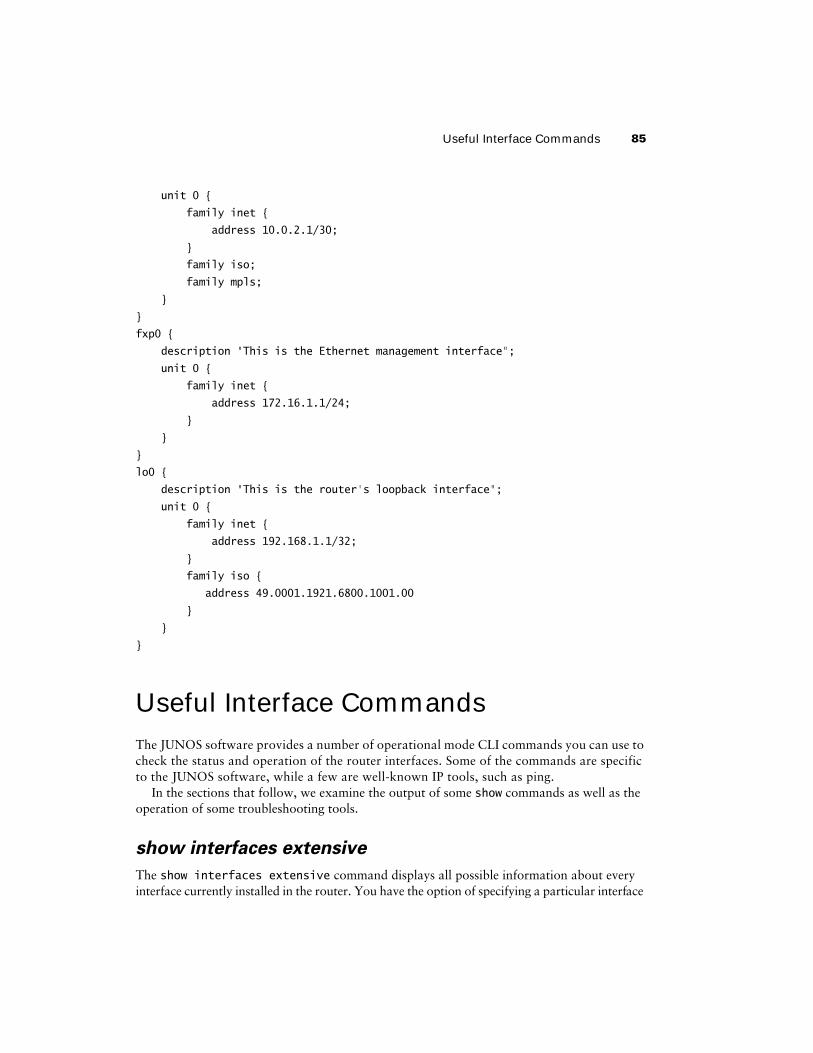
The candidate configuration now appears as such:
[edit interfaces]
user@Cabernet# show
at-0/2/0 {
description "Connection to Merlot";
encapsulation atm-pvc;
atm-options {
vpi 0 maximum-vcs 200;
}
unit 100 {
point-to-point;
vci 0.100;
family inet {
address 10.0.1.1/24;
}
family iso;
family mpls;
}
}
so-2/0/0 {
description "Connection to Riesling";
sonet-options {
fcs 32;
}
Useful Interface Commands 85
unit 0 {
family inet {
address 10.0.2.1/30;
}
family iso;
family mpls;
}
}
fxp0 {
description "This is the Ethernet management interface";
unit 0 {
family inet {
address 172.16.1.1/24;
}
}
}
lo0 {
description "This is the router's loopback interface";
unit 0 {
family inet {
address 192.168.1.1/32;
}
family iso {
address 49.0001.1921.6800.1001.00
}
}
}
Useful Interface CommandsThe JUNOS software provides a number of operational mode CLI commands you can use to check the status and operation of the router interfaces. Some of the commands are specific to the JUNOS software, while a few are well-known IP tools, such as ping.
In the sections that follow, we examine the output of some show commands as well as the operation of some troubleshooting tools.
show interfaces extensive
The show interfaces extensive command displays all possible information about every interface currently installed in the router. You have the option of specifying a particular interface
86 Chapter 2 � Interfaces
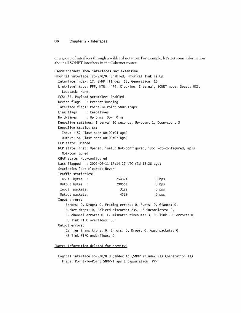
or a group of interfaces through a wildcard notation. For example, let’s get some information about all SONET interfaces in the Cabernet router:
user@Cabernet> show interfaces so* extensive
Physical interface: so-2/0/0, Enabled, Physical link is Up
Interface index: 17, SNMP ifIndex: 53, Generation: 16
Link-level type: PPP, MTU: 4474, Clocking: Internal, SONET mode, Speed: OC3,
Loopback: None,
FCS: 32, Payload scrambler: Enabled
Device flags : Present Running
Interface flags: Point-To-Point SNMP-Traps
Link flags : Keepalives
Hold-times : Up 0 ms, Down 0 ms
Keepalive settings: Interval 10 seconds, Up-count 1, Down-count 3
Keepalive statistics:
Input : 52 (last seen 00:00:04 ago)
Output: 54 (last sent 00:00:07 ago)
LCP state: Opened
NCP state: inet: Opened, inet6: Not-configured, iso: Not-configured, mpls:
Not-configured
CHAP state: Not-configured
Last flapped : 2002-06-11 17:14:27 UTC (3d 18:28 ago)
Statistics last cleared: Never
Traffic statistics:
Input bytes : 254324 0 bps
Output bytes : 290551 0 bps
Input packets: 3122 0 pps
Output packets: 4529 0 pps
Input errors:
Errors: 0, Drops: 0, Framing errors: 0, Runts: 0, Giants: 0,
Bucket drops: 0, Policed discards: 235, L3 incompletes: 0,
L2 channel errors: 0, L2 mismatch timeouts: 3, HS link CRC errors: 0,
HS link FIFO overflows: 00
Output errors:
Carrier transitions: 0, Errors: 0, Drops: 0, Aged packets: 0,
HS link FIFO underflows: 0
(Note: Information deleted for brevity)
Logical interface so-2/0/0.0 (Index 4) (SNMP ifIndex 21) (Generation 11)
Flags: Point-To-Point SNMP-Traps Encapsulation: PPP
Useful Interface Commands 87
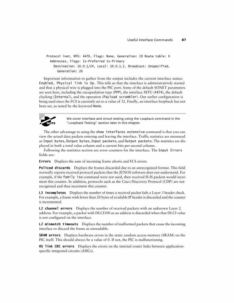
Protocol inet, MTU: 4470, Flags: None, Generation: 19 Route table: 0
Addresses, Flags: Is-Preferred Is-Primary
Destination: 10.0.1/24, Local: 10.0.1.2, Broadcast: Unspecified,
Generation: 26
Important information to gather from the output includes the current interface status: Enabled, Physical link is Up. This tells us that the interface is administratively started and that a physical wire is plugged into the PIC port. Some of the default SONET parameters are seen here, including the encapsulation type (PPP), the interface MTU (4474), the default clocking (Internal), and the operation (Payload scrambler). Our earlier configuration is being used since the FCS is currently set to a value of 32. Finally, an interface loopback has not been set, as noted by the keyword None.
We cover interface and circuit testing using the Loopback command in the “Loopback Testing” section later in this chapter.
The other advantage to using the show interfaces extensive command is that you can view the actual data packets entering and leaving the interface. Traffic statistics are measured as Input bytes, Output bytes, Input packets, and Output packets. The statistics are dis-played in both a total value column and a current bits-per-second column.
Following the statistics section are error counters for the interface. The Input Errors fields are:
Errors Displays the sum of incoming frame aborts and FCS errors.
Policed discards Displays the frames discarded due to an unrecognized format. This field normally reports received protocol packets that the JUNOS software does not understand. For example, if the family iso command were not used, then received IS-IS packets would incre-ment this counter. In addition, protocols such as the Cisco Discovery Protocol (CDP) are not recognized and thus increment this counter.
L3 incompletes Displays the number of times a received packet fails a Layer 3 header check. For example, a frame with fewer than 20 bytes of available IP header is discarded and the counter is incremented.
L2 channel errors Displays the number of received packets with an unknown Layer 2 address. For example, a packet with DLCI100 as an address is discarded when that DLCI value is not configured on the interface.
L2 mismatch timeouts Displays the number of malformed packets that cause the incoming interface to discard the frame as unreadable.
SRAM errors Displays hardware errors in the static random access memory (SRAM) on the PIC itself. This should always be a value of 0. If not, the PIC is malfunctioning.
HS link CRC errors Displays the errors on the internal router links between application-specific integrated circuits (ASICs).
88 Chapter 2 � Interfaces
The possible Output Errors in the display include the following:
Carrier transitions Displays the number of times the interface has gone from a Down state to an Up state. A rapidly incrementing number in this field represents a network problem. Pos-sibilities include the transmission line, the far-end system, or a malfunctioning PIC.
Errors Displays the sum of outgoing frame aborts and FCS errors.
Drops Displays the packets dropped by the output queue of the I/O Manager ASIC.
Aged packets Displays the packets that remained in shared-packet synchronous dynamic random access memory (SDRAM) for so long that the system automatically purged them. The value in this field should never increment.
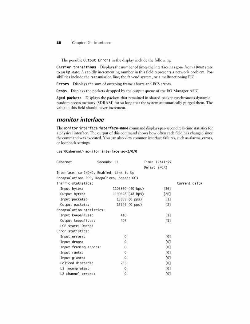
monitor interface
The monitor interface interface-name command displays per-second real-time statistics for a physical interface. The output of this command shows how often each field has changed since the command was executed. You can also view common interface failures, such as alarms, errors, or loopback settings.
user@Cabernet> monitor interface so-2/0/0
Cabernet Seconds: 11 Time: 12:41:55
Delay: 2/0/2
Interface: so-2/0/0, Enabled, Link is Up
Encapsulation: PPP, Keepalives, Speed: OC3
Traffic statistics: Current delta
Input bytes: 1103360 (40 bps) [36]
Output bytes: 1190328 (48 bps) [26]
Input packets: 13839 (0 pps) [3]
Output packets: 15246 (0 pps) [2]
Encapsulation statistics:
Input keepalives: 410 [1]
Output keepalives: 407 [1]
LCP state: Opened
Error statistics:
Input errors: 0 [0]
Input drops: 0 [0]
Input framing errors: 0 [0]
Input runts: 0 [0]
Input giants: 0 [0]
Policed discards: 235 [0]
L3 incompletes: 0 [0]
L2 channel errors: 0 [0]
Useful Interface Commands 89
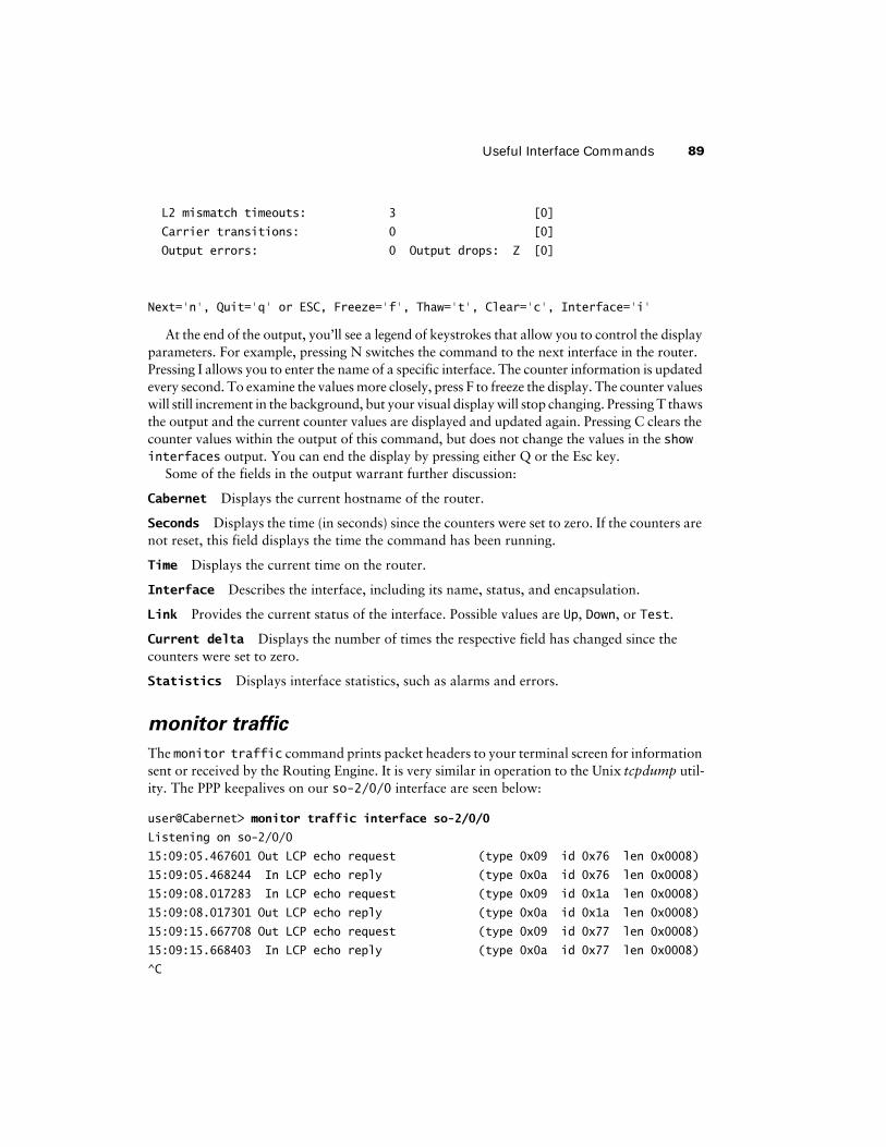
L2 mismatch timeouts: 3 [0]
Carrier transitions: 0 [0]
Output errors: 0 Output drops: Z [0]
Next='n', Quit='q' or ESC, Freeze='f', Thaw='t', Clear='c', Interface='i'
At the end of the output, you’ll see a legend of keystrokes that allow you to control the display parameters. For example, pressing N switches the command to the next interface in the router. Pressing I allows you to enter the name of a specific interface. The counter information is updated every second. To examine the values more closely, press F to freeze the display. The counter values will still increment in the background, but your visual display will stop changing. Pressing T thaws the output and the current counter values are displayed and updated again. Pressing C clears the counter values within the output of this command, but does not change the values in the show interfaces output. You can end the display by pressing either Q or the Esc key.
Some of the fields in the output warrant further discussion:
Cabernet Displays the current hostname of the router.
Seconds Displays the time (in seconds) since the counters were set to zero. If the counters are not reset, this field displays the time the command has been running.
Time Displays the current time on the router.
Interface Describes the interface, including its name, status, and encapsulation.
Link Provides the current status of the interface. Possible values are Up, Down, or Test.
Current delta Displays the number of times the respective field has changed since the counters were set to zero.
Statistics Displays interface statistics, such as alarms and errors.
monitor traffic
The monitor traffic command prints packet headers to your terminal screen for information sent or received by the Routing Engine. It is very similar in operation to the Unix tcpdump util-ity. The PPP keepalives on our so-2/0/0 interface are seen below:
user@Cabernet> monitor traffic interface so-2/0/0
Listening on so-2/0/0
15:09:05.467601 Out LCP echo request (type 0x09 id 0x76 len 0x0008)
15:09:05.468244 In LCP echo reply (type 0x0a id 0x76 len 0x0008)
15:09:08.017283 In LCP echo request (type 0x09 id 0x1a len 0x0008)
15:09:08.017301 Out LCP echo reply (type 0x0a id 0x1a len 0x0008)
15:09:15.667708 Out LCP echo request (type 0x09 id 0x77 len 0x0008)
15:09:15.668403 In LCP echo reply (type 0x0a id 0x77 len 0x0008)
^C
90 Chapter 2 � Interfaces
6 packets received by filter
0 packets dropped by kernel
You use the Ctrl+C keystroke sequence to stop the output and return to the JUNOS software command prompt.
Using the monitor traffic command might affect your router performance. We recommend that you use this option only when other JUNOS software show commands don’t resolve your problem and you need to prove that a packet is actually entering or leaving the router interface.
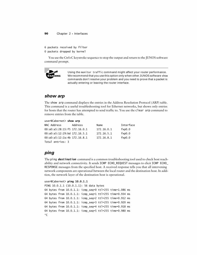
show arp
The show arp command displays the entries in the Address Resolution Protocol (ARP) table. This command is a useful troubleshooting tool for Ethernet networks, but shows only entries for hosts that the router has attempted to send traffic to. You use the clear arp command to remove entries from the table.
user@Cabernet> show arp
MAC Address Address Name Interface
00:a0:a5:28:15:f5 172.16.0.1 172.16.0.1 fxp0.0
00:a0:a5:12:29:bd 172.16.5.1 172.16.5.1 fxp0.0
00:a0:a5:12:2a:4b 172.16.8.1 172.16.8.1 fxp0.0
Total entries: 3
ping
The ping destination command is a common troubleshooting tool used to check host reach-ability and network connectivity. It sends ICMP ECHO_REQUEST messages to elicit ICMP ECHO_RESPONSE messages from the specified host. A received response tells you that all intervening network components are operational between the local router and the destination host. In addi-tion, the network layer of the destination host is operational.
user@Cabernet> ping 10.0.1.1
PING 10.0.1.1 (10.0.1.1): 56 data bytes
64 bytes from 10.0.1.1: icmp_seq=0 ttl=255 time=1.086 ms
64 bytes from 10.0.1.1: icmp_seq=1 ttl=255 time=0.934 ms
64 bytes from 10.0.1.1: icmp_seq=2 ttl=255 time=0.912 ms
64 bytes from 10.0.1.1: icmp_seq=3 ttl=255 time=0.920 ms
64 bytes from 10.0.1.1: icmp_seq=4 ttl=255 time=0.918 ms
64 bytes from 10.0.1.1: icmp_seq=5 ttl=255 time=0.980 ms
^C
Useful Interface Commands 91
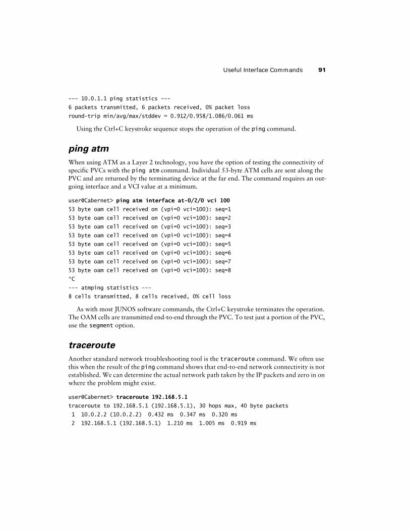
--- 10.0.1.1 ping statistics ---
6 packets transmitted, 6 packets received, 0% packet loss
round-trip min/avg/max/stddev = 0.912/0.958/1.086/0.061 ms
Using the Ctrl+C keystroke sequence stops the operation of the ping command.
ping atm
When using ATM as a Layer 2 technology, you have the option of testing the connectivity of specific PVCs with the ping atm command. Individual 53-byte ATM cells are sent along the PVC and are returned by the terminating device at the far end. The command requires an out-going interface and a VCI value at a minimum.
user@Cabernet> ping atm interface at-0/2/0 vci 100
53 byte oam cell received on (vpi=0 vci=100): seq=1
53 byte oam cell received on (vpi=0 vci=100): seq=2
53 byte oam cell received on (vpi=0 vci=100): seq=3
53 byte oam cell received on (vpi=0 vci=100): seq=4
53 byte oam cell received on (vpi=0 vci=100): seq=5
53 byte oam cell received on (vpi=0 vci=100): seq=6
53 byte oam cell received on (vpi=0 vci=100): seq=7
53 byte oam cell received on (vpi=0 vci=100): seq=8
^C
--- atmping statistics ---
8 cells transmitted, 8 cells received, 0% cell loss
As with most JUNOS software commands, the Ctrl+C keystroke terminates the operation. The OAM cells are transmitted end-to-end through the PVC. To test just a portion of the PVC, use the segment option.
traceroute
Another standard network troubleshooting tool is the traceroute command. We often use this when the result of the ping command shows that end-to-end network connectivity is not established. We can determine the actual network path taken by the IP packets and zero in on where the problem might exist.
user@Cabernet> traceroute 192.168.5.1
traceroute to 192.168.5.1 (192.168.5.1), 30 hops max, 40 byte packets
1 10.0.2.2 (10.0.2.2) 0.432 ms 0.347 ms 0.320 ms
2 192.168.5.1 (192.168.5.1) 1.210 ms 1.005 ms 0.919 ms
92 Chapter 2 � Interfaces
Interface Diagnostic CommandsThe JUNOS software uses two main types of diagnostic configuration to test the physical layer circuitry of an interface: the loopback and BERT tests. You can also use these tools to test the circuit connecting two routers. In this section, we show you how to configure these options and interpret the results using the output of various show commands.
traceroute and the User Datagram Protocol
Since the JUNOS software is based on FreeBSD, it makes sense that the traceroute command uses User Datagram Protocol (UDP) packets in its operation. Most (if not all) Unix-based systems follow this format. It is worth investigating, or reviewing, how traceroute actually operates.
When the command is executed, three UDP packets are generated. Each packet uses the sup-plied end-host information as the destination IP address. The outgoing interface of the router is used as the source IP address. The time-to-live (TTL) value is set to 1 and the destination UDP port is set to 33434. These packets are then sent out into the network.
When the first network device receives the packets, it decrements the TTL field by 1. This results in a new TTL value of 0, which is unusable by an IP device. The network device drops the packet and returns an ICMP TIME_EXCEEDED message to the source IP address of the UDP packet (the local router’s interface). The local router receives these ICMP messages and examines the Source IP Address field. We’ve now found the first network hop along our path!
The local router now sends out three new UDP packets with the same source and destination IP addresses. The UDP port number is incremented by 1 to 33435. The TTL is also incremented by 1 to a new value of 2. The second device along the path repeats the process above by drop-ping the packet and returning an ICMP message to the source. This process repeats itself (UDP port and TTL incrementing each time) for each network device along the path.
When the UDP packets finally reach the end system, they are received and not dropped. After all, the TTL may be set to 1 at that point, but no forwarding of the packet is involved. The IP net-work layer accepts the packet, since the destination IP address is its own interface. The UDP packet is then passed up to the transport layer. The UDP process examines the destination port number to determine whether a session is expecting inbound packets on that port. When no process is found, an ICMP message is again returned to the source IP address. This time, how-ever, it is a PORT_UNREACHABLE message. When the local router receives this ICMP message, it knows that it has reached the far-end system and that the system is active at the network and transport layers.
Interface Diagnostic Commands 93
Loopback Testing
The physical path of a network data circuit usually consists of a number of segments inter-connected by devices that repeat and regenerate the transmission signal. These devices con-nect together in a symmetric pattern. That is, the transmit path on one device connects to the receive path on the next device, and vice versa. Should a circuit fault occur in the form of a line break or a signal corruption due to noise, it is possible to localize the problem by taking advantage of this symmetric segmented system. One of the physical transmission systems sets up a line loopback. Instead of transmitting the signal toward the far-end system, it immedi-ately sends the signal back toward the originating router. Either the originating router sees the loop in the line or it does not. The detection of a loop is achieved when the originating router sees its own data link layer packets return.
If a line loop is set back toward a local router and it is detected, then the problem lies beyond the looping transmission device. Your next step is to set a loop farther away from the local router to locate the problem segment.
When a line loop is set back toward the local router and it is not detected, you can assume the problem lies somewhere between the router and the looped transmission device. In this case, your next troubleshooting step is to set a loop closer to the local router to localize the problem.
Loopback Types
The physical interface on a Juniper Networks router can be set to loop a circuit in either local or remote mode. Both options are configured as a physical interface property and affect the operation of a PIC and its ports.
local Loopback
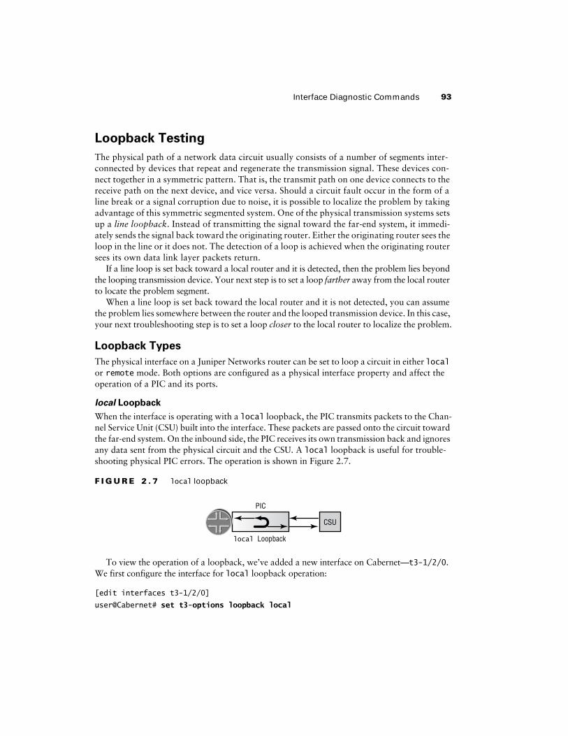
When the interface is operating with a local loopback, the PIC transmits packets to the Chan-nel Service Unit (CSU) built into the interface. These packets are passed onto the circuit toward the far-end system. On the inbound side, the PIC receives its own transmission back and ignores any data sent from the physical circuit and the CSU. A local loopback is useful for trouble-shooting physical PIC errors. The operation is shown in Figure 2.7.
F I G U R E 2 . 7 local loopback
To view the operation of a loopback, we’ve added a new interface on Cabernet—t3-1/2/0. We first configure the interface for local loopback operation:
[edit interfaces t3-1/2/0]
user@Cabernet# set t3-options loopback local
PIC
local Loopback
CSU
94 Chapter 2 � Interfaces
[edit interfaces t3-1/2/0]
user@Cabernet# show
t3-options {
loopback local;
}
After issuing a commit, we verify the current interface status with the show interfaces command:
user@Cabernet> show interfaces t3-1/2/0
Physical interface: t3-1/2/0, Enabled, Physical link is Up
Interface index: 14, SNMP ifIndex: 18
Link-level type: PPP, MTU: 4474, Clocking: Internal
Speed: T3, Loopback: Local, CRC: 16, Mode: C/Bit parity
Device flags : Present Running Loop-Detected
Interface flags: Point-To-Point SNMP-Traps
Link flags : Keepalives
Keepalive settings: Interval 10 seconds, Up-count 1, Down-count 3
Keepalive Input: 7230 (00:00:14 ago), Output: 7266 (00:00:09 ago)
NCP state: Down, LCP state: Conf-req-sent
Input rate : 0 bps (0 pps), Output rate: 0 bps (0 pps)
Active alarms : None
Active defects : None
Logical interface t3-1/2/0.0 (Index 105) (SNMP ifIndex 29)
Flags: Hardware-Down Point-To-Point SNMP-Traps, Encapsulation: PPP
Protocol inet, MTU: 4470, Flags: Protocol-Down
Addresses, Flags: Dest-route-down Is-Preferred Is-Primary
Destination: 175.1.1.0/30, Local: 175.1.1.1
The Loopback: Local output shows us that our configuration was successful. In addition, the PPP keepalives transmitted on the interface are being received by the PIC, which results in a Loop-Detected message in the Device Flags field.
To return the interface to its normal operation, we remove the loopback keyword from the configuration:
[edit interfaces t3-1/2/0]
user@Cabernet# delete t3-options loopback
remote Loopback
The routers on each end of a transmission circuit are also participating in the circuit status. As such, one of the routers can initiate a line loopback toward its far-end partner. This type of envi-ronment tests all the intermediate transmission facilities.
Interface Diagnostic Commands 95
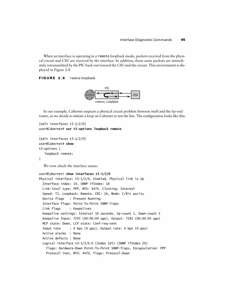
When an interface is operating in a remote loopback mode, packets received from the physi-cal circuit and CSU are received by the interface. In addition, those same packets are immedi-ately retransmitted by the PIC back out toward the CSU and the circuit. This environment is dis-played in Figure 2.8.
F I G U R E 2 . 8 remote loopback
In our example, Cabernet suspects a physical circuit problem between itself and the far-end router, so we decide to initiate a loop on Cabernet to test the line. The configuration looks like this:
[edit interfaces t3-1/2/0]
user@Cabernet# set t3-options loopback remote
[edit interfaces t3-1/2/0]
user@Cabernet# show
t3-options {
loopback remote;
}
We now check the interface status:
user@Cabernet> show interfaces t3-1/2/0
Physical interface: t3-1/2/0, Enabled, Physical link is Up
Interface index: 14, SNMP ifIndex: 18
Link-level type: PPP, MTU: 4474, Clocking: Internal
Speed: T3, Loopback: Remote, CRC: 16, Mode: C/Bit parity
Device flags : Present Running
Interface flags: Point-To-Point SNMP-Traps
Link flags : Keepalives
Keepalive settings: Interval 10 seconds, Up-count 1, Down-count 3
Keepalive Input: 7245 (00:00:09 ago), Output: 7281 (00:00:04 ago)
NCP state: Down, LCP state: Conf-req-sent
Input rate : 0 bps (0 pps), Output rate: 0 bps (0 pps)
Active alarms : None
Active defects : None
Logical interface t3-1/2/0.0 (Index 105) (SNMP ifIndex 29)
Flags: Hardware-Down Point-To-Point SNMP-Traps, Encapsulation: PPP
Protocol inet, MTU: 4470, Flags: Protocol-Down
PIC
remote Loopback
CSU
96 Chapter 2 � Interfaces
Addresses, Flags: Dest-route-down Is-Preferred Is-Primary
Destination: 175.1.1.0/30, Local: 175.1.1.1
The Loopback: Remote output shows the expected configuration. Since Cabernet is not receiving its own keepalives, no Loop-Detected message is seen in the Device Flags field.
Once again, we return to normal operation by removing the loopback keyword from the configuration:
[edit interfaces t3-1/2/0]
user@Cabernet# delete t3-options loopback
BERT Testing
While a loopback test can verify the connectivity of a circuit, it can’t track down poor signal quality due to noise on a line. This is the job of a Bit Error Rate Test (BERT). Many of the interfaces in a Juniper Networks router support BERT testing. These include the T1/E1, T3/E3, CH DS3, CH OC-12, and CH STM-1 interfaces.
A BERT test requires a line loop to be in place on either the transmission devices or the far-end router. The local router generates a known bit pattern and sends it out the transmit path. The received pattern is then verified against the sent pattern. The higher the bit error rate of the received pattern, the worse the noise is on the physical circuit. When the position of the line loop is moved downstream toward the far-end router, you can easily find the troubled portion of the link.
A successful BERT test requires the interface to be configured with the duration of the test, the bit pattern to send on the transmit path, and the error rate to monitor when receiving the inbound pattern.
Configuring the BERT Parameters
The physical interface receives the configuration of the BERT parameters. You configure the duration of the test, the pattern to send in the bit stream, and the error rate to include in the bit stream with the bert-period, bert-algorithm, and bert-error-rate commands, respec-tively. We’ve configured Cabernet’s BERT settings as follows:
[edit interfaces t3-1/2/0]
user@Cabernet# set t3-options bert-period 120
[edit interfaces t3-1/2/0]
user@Cabernet# set t3-options bert-algorithm all-ones-repeating
[edit interfaces t3-1/2/0]
user@Cabernet# set t3-options bert-error-rate 0
[edit interfaces t3-1/2/0]
user@Cabernet# show
Interface Diagnostic Commands 97
t3-options {
bert-algorithm all-ones-repeating;
bert-error-rate 0;
bert-period 120;
}
The run duration lasts from 1 to 240 seconds, with Cabernet running for 120 seconds. The error rate value is an integer between 0 and 7. The supplied value becomes an exponential and results in a final error rate between 10-0 (no errors) and 10-7(1 error in 10 million received bits). The bit patterns to test are too numerous to mention here in detail. Cabernet has opted to send a pattern where every bit is set to a value of 1. Some of the more common testing patterns include:
all-ones-repeating The transmitted pattern is 1111111111111111…
all-zeros-repeating The transmitted pattern is 0000000000000000…
alternating-ones-zeros The transmitted pattern is 1010101010101010…
alternating-double-ones-zeros The transmitted pattern is 1100110011001100…
Starting and Stopping the Test
Once the BERT parameters are committed, you begin the test with the following command:
user@host> test interface t3-1/2/0 t3-bert-start
The test runs for the specified second duration as configured. Should you wish to terminate the test sooner, use the following command:
user@host> test interface t3-1/2/0 t3-bert-stop
BERT Test Results
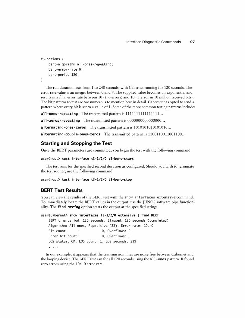
You can view the results of the BERT test with the show interfaces extensive command. To immediately locate the BERT values in the output, use the JUNOS software pipe function-ality. The find string option starts the output at the specified string:
user@Cabernet> show interfaces t3-1/2/0 extensive | find BERT
BERT time period: 120 seconds, Elapsed: 120 seconds (completed)
Algorithm: All ones, Repetitive (22), Error rate: 10e-0
Bit count : 0, Overflows: 0
Error bit count: 0, Overflows: 0
LOS status: OK, LOS count: 1, LOS seconds: 239
. . .
In our example, it appears that the transmission lines are noise free between Cabernet and the looping device. The BERT test ran for all 120 seconds using the all-ones pattern. It found zero errors using the 10e-0 error rate.
98 Chapter 2 � Interfaces
SummaryIn this chapter, we’ve seen that a Juniper Networks router has both permanent and transient interfaces. These interfaces use a distinct and common naming structure that relates directly to their physical location in the platform. We also discussed differences between the physical and logical properties of an interface. These properties translate into the operation of the specific physical media and the logical Layer 2 and 3 addressing of the interface.
We then looked at some examples of configuring the various protocol families within the JUNOS software. Next, we examined some commands used to verify the operation and status of an interface. Finally, we described two methods for testing the physical circuits connecting two routers—loopback and BERT testing.
Exam EssentialsUnderstand the JUNOS software interface naming convention. The format consists of a two-character media type designator followed by the FPC slot number, the PIC slot number within an FPC, the port number on the PIC, and the logical unit. The format is media_type-fpc/pic/port.unit.
Know the differences between a permanent and a transient interface. Each Juniper Networks router contains the fxp0 and fxp1 permanent interfaces. All interfaces contained on a PIC are considered transient because they can be removed at any time.
Be able to list the protocol families available for configuration on an interface. The inet, inet6, iso, and mpls protocol families are configurable on a Juniper Networks interface.
Know the logical properties available on an interface. Each interface in the JUNOS software requires some logical properties. These often include the Layer 3 and Layer 2 addressing infor-mation for enabling proper network operation.
Be able to identify the major fields in the show interfaces extensive command. Infor-mation such as the current status, input/output byte and packet statistics, and input/output error counters are available in the command output.
Understand the interface diagnostic options available in the JUNOS software. Both loopback and BERT testing help you locate trouble spots on a physical network circuit.

Key Terms 99
Key TermsBefore you take the exam, be certain you are familiar with the following terms:
Asynchronous Transfer Mode (ATM) maximum transmission unit (MTU)
Bit Error Rate Test (BERT) mpls protocol family
data link connection identifiers (DLCIs) permanent interfaces
deactivate permanent virtual circuit (PVC)
disable Physical Interface Card (PIC)
Flexible PIC Concentrator (FPC) Point-to-Point Protocol (PPP)
Frame Relay preferred address
fxp0 primary address
fxp1 protocol address
High-Level Data Link Control (HDLC) protocol families
inet protocol family quad-wide
inet6 protocol family tcpdump
Internal Ethernet transient interfaces
iso protocol family unit
keepalive virtual circuit identifier (VCI)
line loopback virtual local area networks (VLANs)
Management Ethernet virtual path identifier (VPI)
100 Chapter 2 � Interfaces
Review Questions1. What is the correct order of elements in the JUNOS software interface naming convention?
A. FPC, PIC, port, type
B. Type, port, PIC, FPC
C. Type, FPC, PIC, port
D. Port, PIC, FPC, type
2. How are the FPC slot numbers for an M40e numbered?
A. 0 through 3, top to bottom
B. 0 through 7, left to right
C. 0 through 7, top to bottom
D. 1 through 8, left to right
3. How are the PIC slots numbered on an M20 FPC?
A. 0 through 3, top to bottom
B. 0 through 3, left to right
C. 0 through 3, bottom to top
D. 0 through 3, right to left
4. There are two different types of interfaces on a Juniper Networks router. What are they?
A. Permanent and transient
B. Transient and logical
C. Physical and logical
D. Permanent and logical
5. Which properties are examples of a physical interface configuration? (Choose three.)
A. Keepalives
B. IP Address
C. Description
D. FCS
6. Which properties are examples of a logical interface configuration? (Choose two.)
A. DLCI number
B. Scrambling
C. FCS Value
D. Protocol MTU

Review Questions 101
7. What prefix length is assigned to an IPv4 address if you do not specify one in the configuration?
A. The command fails the syntax check.
B. The command fails the commit check.
C. The router assigns a /32 prefix length.
D. The router assigns a classful network prefix length.
8. Which command displays the status of all SONET interfaces on the router?
A. show ip interfaces brief
B. show sonet interfaces terse
C. show interfaces so-* terse
D. show so-* interfaces
9. An interface has multiple IP addresses configured. Which of the following statements is true about the interface’s primary address?
A. It is the highest numbered address on the interface.
B. It is the lowest numbered address on the interface.
C. Each configured address is considered to be a primary address.
D. There is no default primary address.
10. What is the result of using the deactivate command?
A. The configuration is ignored and not applied.
B. The interface configuration is marked deactivated.
C. The physical interface status changes to Admin Down.
D. The logical interface status changes to Admin Down.
11. In the show interfaces extensive output, which field displays framing errors?
A. Input Errors
B. Input policed discards
C. Input L2 channel errors
D. Input HS link CRC errors
12. Which field in the show interfaces extensive output displays received packets with a damaged IP header?
A. active alarms
B. output carrier transitions
C. input policed discards
D. input L3 incompletes
102 Chapter 2 � Interfaces
13. A Frame Relay interface is configured to support DLCI values 40, 50, and 60. Incoming frames show a DLCI 45. Which field in the show interfaces extensive output displays this information?
A. active alarms
B. output carrier transitions
C. input policed discards
D. input L2 channel errors
14. The monitor traffic command closely resembles what Unix-based utility?
A. pwd
B. ps –aux
C. tcpdump
D. ls –a–l
15. The monitor traffic command can evaluate traffic _____. (Choose two.)
A. Inbound on interface at-0/2/0.100 destined for the Routing Engine
B. Outbound on interface at-0/2/0.100 from the Routing Engine
C. Inbound on interface at-0/2/0.100 destined for interface so-2/0/0.0
D. Outbound on interface at-0/2/0.100 from interface so-2/0/0.0
16. Which command allows a network administrator to view locally sourced BGP keepalive packet headers on interface so-2/0/0.0?
A. monitor interface so-2/0/0.0
B. monitor traffic interface so-2/0/0.0
C. monitor bgp interface so-2/0/0.0
D. tcpdump interface so-2/0/0.0
17. When a local loopback is configured on an interface, which of the following statements is true?
A. Traffic received on the interface is looped back to the other end of the link.
B. Traffic sent on the interface is looped back to the router on another interface.
C. Traffic sent by the router is looped back to the router on the same interface.
D. Traffic received by the router is looped back to the router on the same interface.
18. What command is used to check the status of a configured loopback?
A. show interface terse
B. show interface extensive
C. monitor interface terse
D. monitor interface extensive
Review Questions 103
19. Which parameters are used for BERT testing? (Choose two.)
A. bert-algorithm
B. bert-error-rate
C. bert-pattern
D. bert-seconds
20. Which JUNOS software command starts a BERT test?
A. test interface t3-1/0/1 t3-bert-start
B. interface test t3-1/0/1 t3-bert-start
C. interface t3-1/0/1 t3-bert-start
D. test interface t3-1/0/1 t3-bert-begin

104 Chapter 2 � Interfaces
Answers to Review Questions1. C. The correct order is media type, FPC slot number, PIC slot number, and PIC port number.
2. B. An M40e has eight vertical FPC slots. They are numbered 0 through 7, left to right.
3. D. An M20 has four PIC slots in each FPC. Since the FPC has a horizontal orientation, the PIC slots are numbered 0 through 3, right to left.
4. A. Juniper Networks routers have two types of interfaces: permanent and transient.
5. A, C, D. Only the protocol address is a logical property of an interface.
6. A, D. DLCIs and protocol MTU are both logical interface properties. Scrambling and descrip-tion are physical properties.
7. C. In the absence of a prefix length, the router assumes a 32-bit prefix length for an IPv4 address.
8. C. An asterisk (*) may be used as a wildcard character. The command show interface so-* terse will display the status of all SONET interfaces on the router.
9. B. An interface contains only a single primary address and, by default, it is the lowest numerical prefix on the interface.
10. A. When an interface has been deactivated, the interface is marked inactive and the config-uration statements are ignored when the candidate configuration is committed.
11. A. Input Errors are the sum of the incoming frame aborts and FCS errors.
12. D. The input L3 incompletes field is a counter that is incremented when the incoming packet fails Layer 3 (usually IPv4) checks of the header.
13. D. The input L2 channel errors field is a counter that increments when the software cannot find a valid logical interface for an incoming frame.
14. C. The Unix-based tcpdump utility closely resembles the monitor traffic command.
15. A, B. The monitor traffic command can be used to track any packets destined to, or coming from, the Routing Engine over a particular interface.
16. B. The command monitor traffic interface so-2/0/0.0 allows you to view packet headers. monitor interface so-2/0/0.0 displays packet, byte, and error counters in real time. Answers C and D are not valid JUNOS software commands.
17. C. Traffic sent by the router is looped back to the router on the same interface. A remote loop-back will loop traffic received on the interface back to the other end of the link.
18. B. The command show interface extensive is used to check if an interface has a loopback set. Answer A displays only the interface up/down status and all logical configuration. Answers C and D are not valid JUNOS software commands.

Answers to Review Questions 105
19. A, B. The bert-algorithm parameter is used to specify the test pattern. The bert-error-rate parameter is used to examine the received pattern.
20. A. The correct command is test interface t3-1/0/1 t3-bert-start.