Embed Size (px)
Citation preview

J.J. Thomson, Philos. Mag. 44, 293 1897
Cathode Rays.
J.J. Thomson,(Received October, 1897)
The experiments1 discussed in this paper were undertaken in the hopeof gaining, some information; is to the nature of the Cathode Rays. Themost diverse opinions are held as to these rays; according to the almostunanimous opinion of German physicists they are due to some process inthe æther to which–inasmuch as in a uniform magnetic field their course iscircular and not rectilinear-no phenomenon hitherto observed is analogous:another view of these rays is that, so far from being wholly authorial, theyare in fact wholly material, and that they mark the paths of particles ofmatter charged with negative electricity. It would seem at first sight thatit ought not to be di!cult to discriminate between views so di"erent, yetexperience shows that this is not the case, as amongst the physicists whohave most deeply studied the subject can be found supporters of eithertheory.The electrified–particle theory has fur purposes of research a great ad-
vantage over the ætherial theory, since it is definite and its consequencescan be predicted; with the ætherial theory it is impossible to predict whatwill happen under any given circumstances, as on this theory we are dealingwith hitherto unobserved phenomena in the æther, of whose laws we areignorant.The following experiments were made to test some of the consequences
of the electrified-particle theory.
1Some of these experiments have already been described in a paper real before theCambrige Philosophical Society (Proceedings, vol. IX. 1897), and in a Friday EveningDiscourse at the Royal Institution (‘Electrician,’ May 21, 1897).
1
Charge carried by the Cathode Rays.
If these rays are negatively electrified particles, then when they enter anenclosure they ought to carry into it a charge of negative electricity. This hasbeen proved to he the ease by Perrin, who placed in front of a plane cathodetwo coaxial metallic cylinders which were insulated from each other: theouter of these cylinders was connected with the earth, the inner with a gold–leaf electroscope. These cylinders were closed except for two small holes,one in each cylinder, placed so that the cathode rays could pass throughthem into the inside of the inner cylinder. Perrin found that when the rayspassed into the inner cylinder the electroscope received a charge of negativeelectricity, while no charge went to the electroscope when the rays weredeflected by a magnet so as no longer to pass through the hole.This experiment proves that something charged with negative electricity
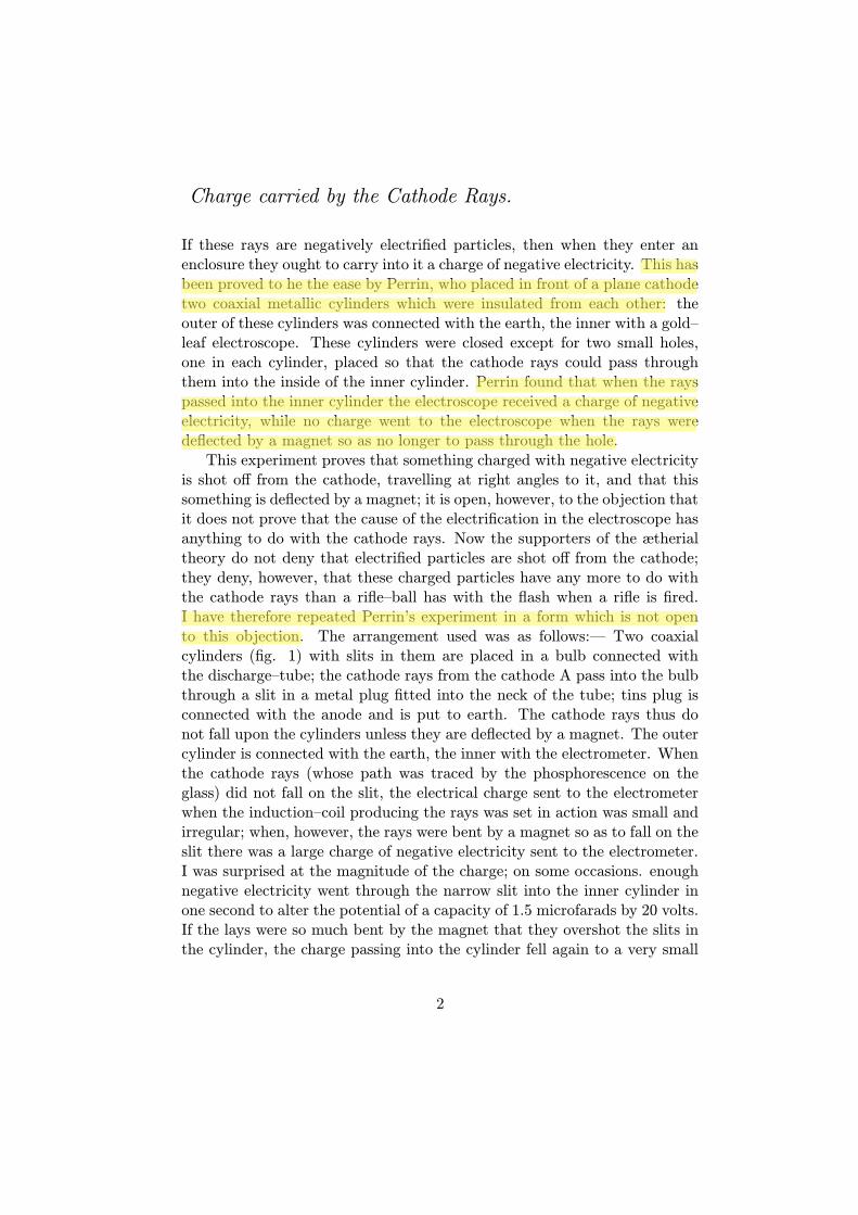
is shot o" from the cathode, travelling at right angles to it, and that thissomething is deflected by a magnet; it is open, however, to the objection thatit does not prove that the cause of the electrification in the electroscope hasanything to do with the cathode rays. Now the supporters of the ætherialtheory do not deny that electrified particles are shot o" from the cathode;they deny, however, that these charged particles have any more to do withthe cathode rays than a rifle–ball has with the flash when a rifle is fired.I have therefore repeated Perrin’s experiment in a form which is not opento this objection. The arrangement used was as follows:— Two coaxialcylinders (fig. 1) with slits in them are placed in a bulb connected withthe discharge–tube; the cathode rays from the cathode A pass into the bulbthrough a slit in a metal plug fitted into the neck of the tube; tins plug isconnected with the anode and is put to earth. The cathode rays thus donot fall upon the cylinders unless they are deflected by a magnet. The outercylinder is connected with the earth, the inner with the electrometer. Whenthe cathode rays (whose path was traced by the phosphorescence on theglass) did not fall on the slit, the electrical charge sent to the electrometerwhen the induction–coil producing the rays was set in action was small andirregular; when, however, the rays were bent by a magnet so as to fall on theslit there was a large charge of negative electricity sent to the electrometer.I was surprised at the magnitude of the charge; on some occasions. enoughnegative electricity went through the narrow slit into the inner cylinder inone second to alter the potential of a capacity of 1.5 microfarads by 20 volts.If the lays were so much bent by the magnet that they overshot the slits inthe cylinder, the charge passing into the cylinder fell again to a very small
2
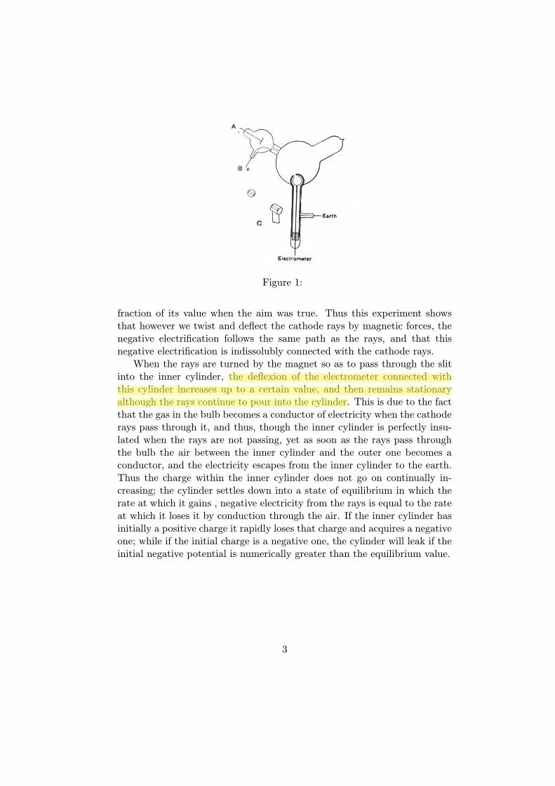
Figure 1:
fraction of its value when the aim was true. Thus this experiment showsthat however we twist and deflect the cathode rays by magnetic forces, thenegative electrification follows the same path as the rays, and that thisnegative electrification is indissolubly connected with the cathode rays.When the rays are turned by the magnet so as to pass through the slit
into the inner cylinder, the deflexion of the electrometer connected withthis cylinder increases up to a certain value, and then remains stationaryalthough the rays continue to pour into the cylinder. This is due to the factthat the gas in the bulb becomes a conductor of electricity when the cathoderays pass through it, and thus, though the inner cylinder is perfectly insu-lated when the rays are not passing, yet as soon as the rays pass throughthe bulb the air between the inner cylinder and the outer one becomes aconductor, and the electricity escapes from the inner cylinder to the earth.Thus the charge within the inner cylinder does not go on continually in-creasing; the cylinder settles down into a state of equilibrium in which therate at which it gains , negative electricity from the rays is equal to the rateat which it loses it by conduction through the air. If the inner cylinder hasinitially a positive charge it rapidly loses that charge and acquires a negativeone; while if the initial charge is a negative one, the cylinder will leak if theinitial negative potential is numerically greater than the equilibrium value.
3
Deflexion of the Cathode Rays by an Electrostatic Field.
An objection very generally urged against the view that the cathode raysare negatively electrified particles, is that hitherto no deflexion of the rayshas been observed under a small electrostatic force, and though the raysare deflected when they pass near electrodes connected with sources of largedi"erences of potential, such as induction–coils or electrical machines, thedeflexion in this case is regarded by the supporters of the ætherial theoryas due to the discharge passing between the electrodes, and not primarilyto the electrostatic field. Hertz made the rays travel between two parallelplates of metal placed inside the discharge–tube, but found that they werenot deflected when the plates were connected with a battery of storage–cells;on repeating this experiment I at first got the same result, but subsequentexperiments showed that the absence of deflexion is due to the conductiv-ity conferred on the rarefied gas by the cathode rays. On measuring thisconductivity it was found that it diminished very rapidly as the exhaustionincreased; it seemed then that on trying Hertz’s experiment at very high ex-haustions there might be a chance of detecting the deflexion of the cathoderays by an electrostatic force.The apparatus used is represented in fig.2.The rays from the cathode C pass through a slit in the anode A, which is
a metal plug fitting tightly into the tube and connected with the earth; afterpassing through a second slit in another earth–connected metal plug B, theytravel between two parallel aluminium plates about 5 cm. long by 2 broadand at a distance of 1.5 cm. apart; they then fall on the end of the tubeand produce a narrow well–defined phosphorescent patch. A scale pastedon the outside of the tube serves to measure the deflexion of this patch.At high exhaustions the rays were deflected when the two aluminium plateswere connected with the terminals of a battery of small storage–cells; therays were depressed when the upper plate was connected with the negativepole of the battery, the lower with the positive, and raised when the upperplate was connected with the positive, the lower with the negative pole. Thedeflexion was proportional to the di"erence of potential between the plates,and I could detect the deflexion when the potential–di"erence was as smallas two volts. It was only when the vacuum was a good one that the deflexiontook place, but that the absence of deflexion is due to the conductivity of themedium is shown by what takes place when the vacuum has just arrived atthe stage at which the deflexion begins. At this stage there is a deflexion ofthe rays when the plates are first connected with the terminals of the battery,
4
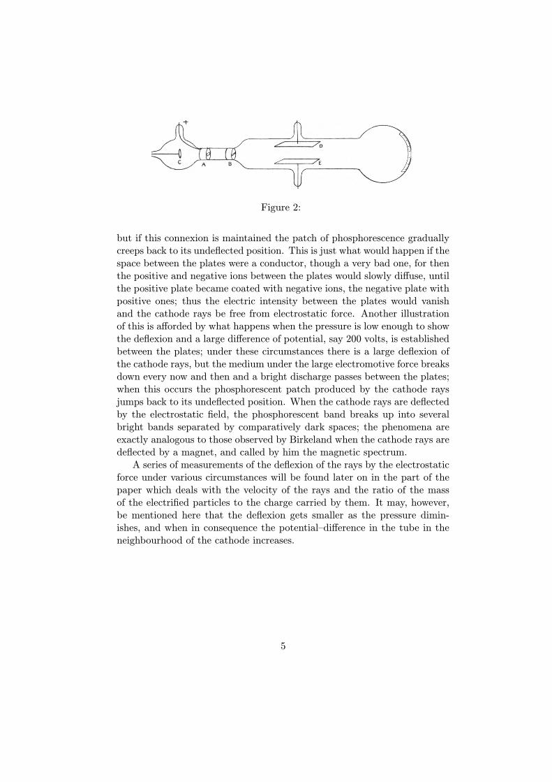
Figure 2:
but if this connexion is maintained the patch of phosphorescence graduallycreeps back to its undeflected position. This is just what would happen if thespace between the plates were a conductor, though a very bad one, for thenthe positive and negative ions between the plates would slowly di"use, untilthe positive plate became coated with negative ions, the negative plate withpositive ones; thus the electric intensity between the plates would vanishand the cathode rays be free from electrostatic force. Another illustrationof this is a"orded by what happens when the pressure is low enough to showthe deflexion and a large di"erence of potential, say 200 volts, is establishedbetween the plates; under these circumstances there is a large deflexion ofthe cathode rays, but the medium under the large electromotive force breaksdown every now and then and a bright discharge passes between the plates;when this occurs the phosphorescent patch produced by the cathode raysjumps back to its undeflected position. When the cathode rays are deflectedby the electrostatic field, the phosphorescent band breaks up into severalbright bands separated by comparatively dark spaces; the phenomena areexactly analogous to those observed by Birkeland when the cathode rays aredeflected by a magnet, and called by him the magnetic spectrum.A series of measurements of the deflexion of the rays by the electrostatic
force under various circumstances will be found later on in the part of thepaper which deals with the velocity of the rays and the ratio of the massof the electrified particles to the charge carried by them. It may, however,be mentioned here that the deflexion gets smaller as the pressure dimin-ishes, and when in consequence the potential–di"erence in the tube in theneighbourhood of the cathode increases.
5
Conductivity of a Gas through which Cathode Rays arepassing.
The conductivity of the gas was investigated by means of the apparatusshown in fig. 2. The upper plate D was connected with one terminal of abattery of small storage–cells, the other terminal of which was connectedwith the earth; the other plate E was connected with one of the coatingsof a condenser of one microfarad capacity, the other coating of which wasto earth; one pair of quadrants of an electrometer was also connected withE, the other pair of quadrants being to earth. When the cathode rays arepassing between the plates the two pairs of quadrants of the electrometer arefirst connected with each other, and then the connexion between them wasbroken. If the space between the plates were a non–conductor, the potentialof the pair of quadrants not connected with the earth would remain zeroand the needle of the electrometer would not move; if, however, the spacebetween the plates were a conductor, then the potential of the lower platewould approach that of the upper, and the needle of the electrometer wouldbe deflected. There is always a deflexion of the electrometer, showing thata current passes between the plates. The magnitude of the current dependsvery greatly upon the pressure of the gas; so much so, indeed, that it isdi!cult, to obtain consistent readings in consequence of the changes whichalways occur in the pressure when the discharge passes through the tube.We shall first take the case when the pressure is only just low enough to
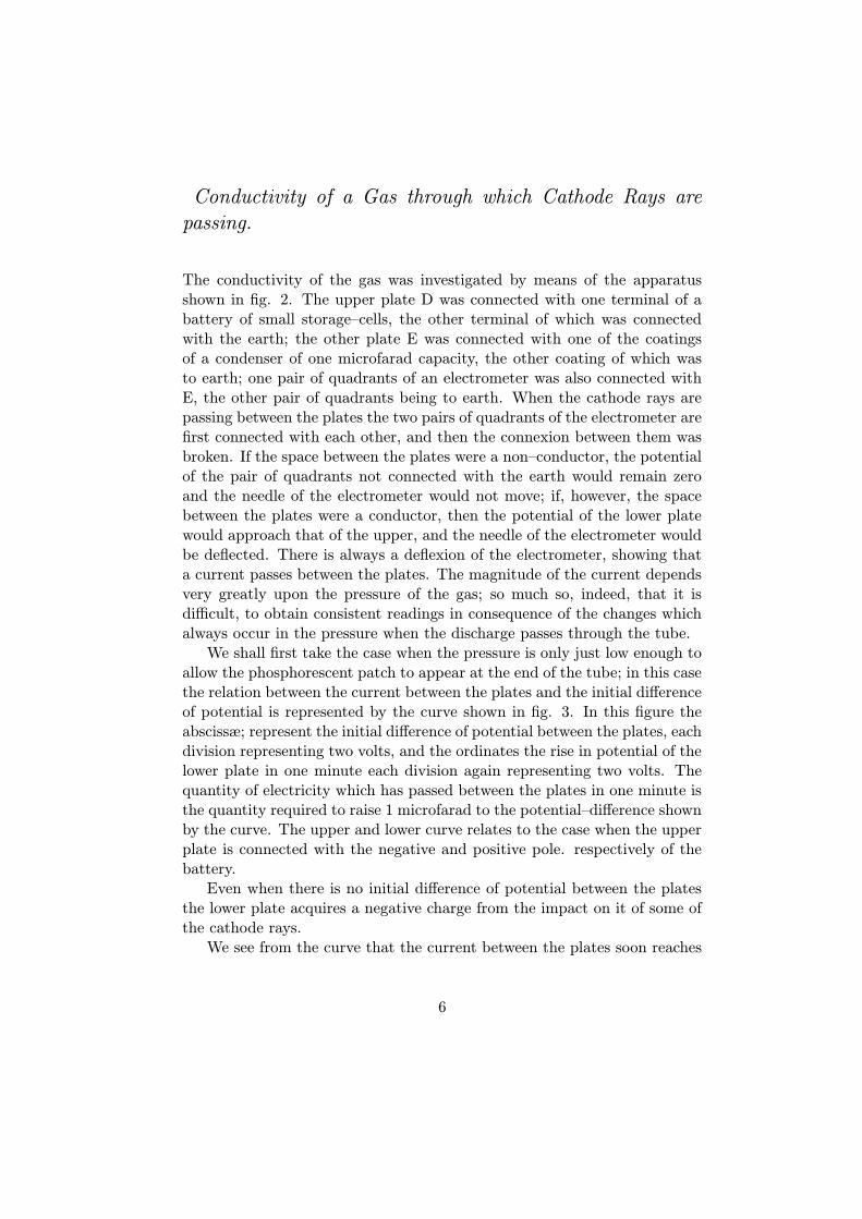
allow the phosphorescent patch to appear at the end of the tube; in this casethe relation between the current between the plates and the initial di"erenceof potential is represented by the curve shown in fig. 3. In this figure theabscissæ; represent the initial di"erence of potential between the plates, eachdivision representing two volts, and the ordinates the rise in potential of thelower plate in one minute each division again representing two volts. Thequantity of electricity which has passed between the plates in one minute isthe quantity required to raise 1 microfarad to the potential–di"erence shownby the curve. The upper and lower curve relates to the case when the upperplate is connected with the negative and positive pole. respectively of thebattery.Even when there is no initial di"erence of potential between the plates
the lower plate acquires a negative charge from the impact on it of some ofthe cathode rays.We see from the curve that the current between the plates soon reaches
6
Figure 3:
a value where it is only slightly a"ected by an increase in the potential–di"erence between the plates; this is a feature common to conduction throughgases traversed by Rontgen rays, by uranium rays, by ultra–violet light, and,as we now see, by cathode rays. The rate of leak is not greatly di"erentwhether the upper plate be initially positively or negatively electrified.The current between the plates only lasts for a short time; it ceases long
before the potential of the lower plate approaches that of the upper. Thus,for example, when the potential of the upper plate was about 400 volts abovethat of the earth, the potential of the lower plate never rose above 6 volts:similarly, if the upper plate were connected with the negative pole of thebattery, the fall in potential of the lower plate was very small in comparisonwith the potential-di"erence between the upper plate and the earth.These results are what we should expect if the gas between the plates
and the plug B (fig. 2) were a very much better conductor than the gasbetween the plates, for the lower plate will be in a steady state when thecurrent coming to it from the upper plate is equal to the current going fromit to the plug: now if the conductivity of the gas between the plate andthe plug is much greater than that between the plates, a small di"erenceof potential between the lower plate and the plug will be consistent with atarge potential–di"erence between the plates.So far we have been considering the case when the pressure is as high as
is consistent with the cathode rays reaching the end of the tube; we shallnow go to the other extreme and consider the case when the pressure is aslow as is consistent with the passage of a discharge through the bulb. In thiscase, when the plates are not connected with the battery we got a negativecharge communicated to the lower plate, but only very slowly in comparisonwith the e"ect in the previous case. When the upper plate is connected withthe negative pole of a battery, this current to the lower plate is only slightlyincreased even when the di"erence of potential is as much as 400 volts: asmall potential–di"erence of about 20 volts seems slightly to decrease the
7
rate of leak. Potential–di"erences much exceeding 400 volts cannot; be used,as though the dielectric between the plates is able to sustain them for somelittle time, yet after a time an intensely bright arc flashes across betweenthe plates and liberates so much gas as to spoil the vacuum. The lines inthe spectrum of this glare are chiefly mercury lines; its passage leaves verypeculiar markings on the aluminium plates.If the upper plate was charged positively, then the negative charge com-
municated to the lower plate was diminished, and stopped when the potential–di"erence between the plates was about 20 volts; but at the lowest pressure,however great (up to 400 volts) the potential–di"erence, there was no leak ofpositive electricity to the lower plate at all comparable with the leak of neg-ative electricity to this plate when the two plates were disconnected fromthe battery. In fact at this very low pressure all the facts are consistentwith the view that the e"ects are due to the negatively electrified particlestravelling along the cathode rays, the rest of the gas possessing little con-ductivity. Some experiments were made with a tube similar to that shownin fig. 2, with the exception that the second plug B was absent, so that amuch greater number of cathode rays passed between the plates. When theupper plate was connected with the positive pole of the battery a luminousdischarge with well–marked striations passed between the upper plate andthe earth–connected plug through which the cathode rays were streaming;this occurred even though the potential–di"erence between the plate andthe plug did not exceed 20 volts. Thus it seems that if we supply cathoderays from an external source to the cathode a small potential–di"erence issu!cient to produce the characteristic discharge through a gas.
Magnetic Deflexion of the Cathode Rays in Di!erent Gases.
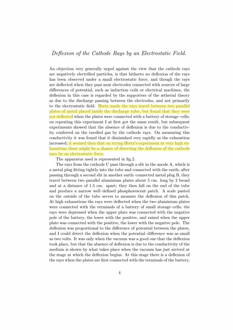
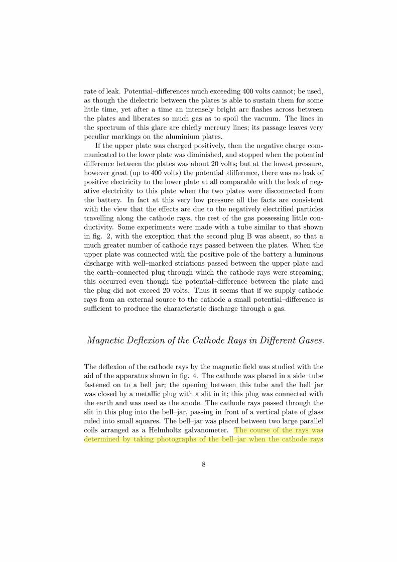
The deflexion of the cathode rays by the magnetic field was studied with theaid of the apparatus shown in fig. 4. The cathode was placed in a side–tubefastened on to a bell–jar; the opening between this tube and the bell–jarwas closed by a metallic plug with a slit in it; this plug was connected withthe earth and was used as the anode. The cathode rays passed through theslit in this plug into the bell–jar, passing in front of a vertical plate of glassruled into small squares. The bell–jar was placed between two large parallelcoils arranged as a Helmholtz galvanometer. The course of the rays wasdetermined by taking photographs of the bell–jar when the cathode rays
8

Figure 4:
were passing through it; the divisions on the plate enabled the path of therays to be determined. Under the action of the magnetic field the narrowbeam of cathode rays spreads out into a broad fan–shaped luminosity in thegas. The luminosity in this fan is not uniformlydistributed, but is condensed along certain lines. The phosphorescence onthe glass is also not uniformly distributed; it is much spread out, showingthat the beam consists of rays which are not all deflected to the same ex-tent by the magnet. The luminosity on the glass is crossed by bands alongwhich the luminosity is very much greater than in the adjacent parts. Thesebright and dark bands are called by Birkeland, who first observed them,the magnetic spectrum. The brightest spots on the glass are by no meansalways the terminations of the brightest streaks of luminosity in the gas; infact, in some cases a very bright spot on the glass is not connected withthe cathode by any appreciable luminosity, though there may be plenty ofluminosity in other parts of the gas. One very interesting point brought outby the photographs is that in a given magnetic field, and with a given meanpotential–di"erence between the terminals, the path of the rays is indepen-dent of the nature of the gas. Photographs were taken of the discharge inhydrogen, air, carbonic acid, methyl iodide, i.e., in gases whose densitiesrange from 1 to 70, and yet, not only were the paths of the most deflectedrays the same in all cases, but even the details, such as the distribution ofthe bright and dark spaces, were the same; in fact, the photographs couldhardly be distinguished from each other. It is to be noted that the pressureswere not the same; the pressures in the di"erent gases were adjusted so thatthe mean potential–di"erences between the cathode and the anode were thesame in all the gases. When the pressure of a gas is lowered, the potential–di"erence between the terminal increases, and deflexion of the rays producedby a magnet diminishes, or at any rate the deflexion of the rays when the
9
phosphorescence is a maximum diminishes. If an air–break is inserted ane"ect of the same kind is produced.In the experiments with di"erent gases, the pressures were as high as
was consistent with the appearance of the phosphorescence on the glass, soas to ensure having as much as possible of the gas under consideration inthe tube.As the cathode rays carry a charge of negative electricity, are deflected
by an electrostatic force as if they were negatively electrified, and are actedon by a magnetic force in just the way in which this force would act on anegatively electrified body moving along the path of these rays, I can seeno escape from the conclusion that they are charges of negative electricitycarried by particles of matter. The question next arise, What are theseparticles? are they atoms, or molecules, or matter in a still finer stateof subdivision? To throw some light on this point, I have made a seriesof measurements of the ratio of the mass of these particles to the chargecarried by it. To determine this quantity, I have used two independentmethods. The first of these is as follows : — Suppose we consider a bundleof homogeneous cathode rays. Let m be the mass of each of the particles,e the charge carried by it. Let N be the number of particles passing acrossany section of the beam in a given time; then Q the quantity of electricitycarried by these particles is given by the equation
Ne = Q.
We can measure Q if we receive the cathode rays in the inside of a vesselconnected with an electrometer. When these rays strike against a solid body,the temperature of the body is raised; the kinetic energy of the movingparticles being converted into heat; if we suppose that all this energy isconverted into heat, then if we measure the increase in the temperature ofa body of known thermal capacity caused by the impact of these rays, wecan determine W , the kinetic energy of the particles, and if v is the velocityof the particles,
1
2Nmv2 =W.
If ! the radius of curvature of the path of these rays in a uniform magneticfield H, then
mv
e= H! = I,
where I is written for Hp for the sake of brevity. From these equations weget.
1
2
m
ev2 =
W
Q.
10

v =2W
QI,
m
e=I2Q
2W.
Thus, if we know the values of Q, W , and I, we can deduce the values of vand m/e.To measure these quantities, I have used tubes of three di"erent types.
The first I tried is like that represented in fig. 2, except that the platesE and D are absent, and two coaxial cylinders are fastened to the end ofthe tube. The rays from the cathode C fall on the metal plug B, whichis connected with the earth, and serves for the anode; a horizontal slit iscut in this plug. The cathode rays pass through this slit, and then strikeagainst the two coaxial cylinders at the end of the tube; slits are cut inthese cylinders, so that the cathode rays pass into the inside of the innercylinder. The outer cylinder is connected with the earth, the inner cylinder,which is insulated from the outer one, is connected with an electrometer,the deflexion of which measures Q, the quantity of electricity brought intothe inner cylinder by the rays. A thermo–electric couple is placed behindthe slit in the inner cylinder; this couple is made of very thin strips ofiron and copper fastened to very fine iron and copper wires. These wirespassed through the cylinders, being insulated from them, and through theglass to the outside of the tube, where they were connected with a low–resistance galvanometer, the deflexion of which gave data for calculating therise of temperature of the junction produced by the impact against it of thecathode rays. The strips of iron and copper were large enough to ensurethat every cathode ray which entered the inner cylinder struck against thejunction. In some of the tubes the strips of iron and copper were placedend to end, so that some of the rays struck against the iron, and othersagainst the copper; in others, the strip of one metal was placed in front ofthe other; no di"erence, however, could be detected between the results gotwith these two arrangements. The strips of iron and copper were weighed,and the thermal capacity of the junction calculated. In one set of junctionsthis capacity was 5 ! 10!3, in another 3 ! 10!3. If we assume that thecathode rays which strike against the junction give their energy up to it, thedeflexion of the galvanometer gives us W or 1/2 Nmv2.The value of I, i. e., H!, where ! is the curvature of this path of the
rays in a magnetic field of strength H was found as follows:— The tubewas fixed between two large circular coils placed parallel to each other, andseparated by a distance equal to the radius of either; these coils produce a
11
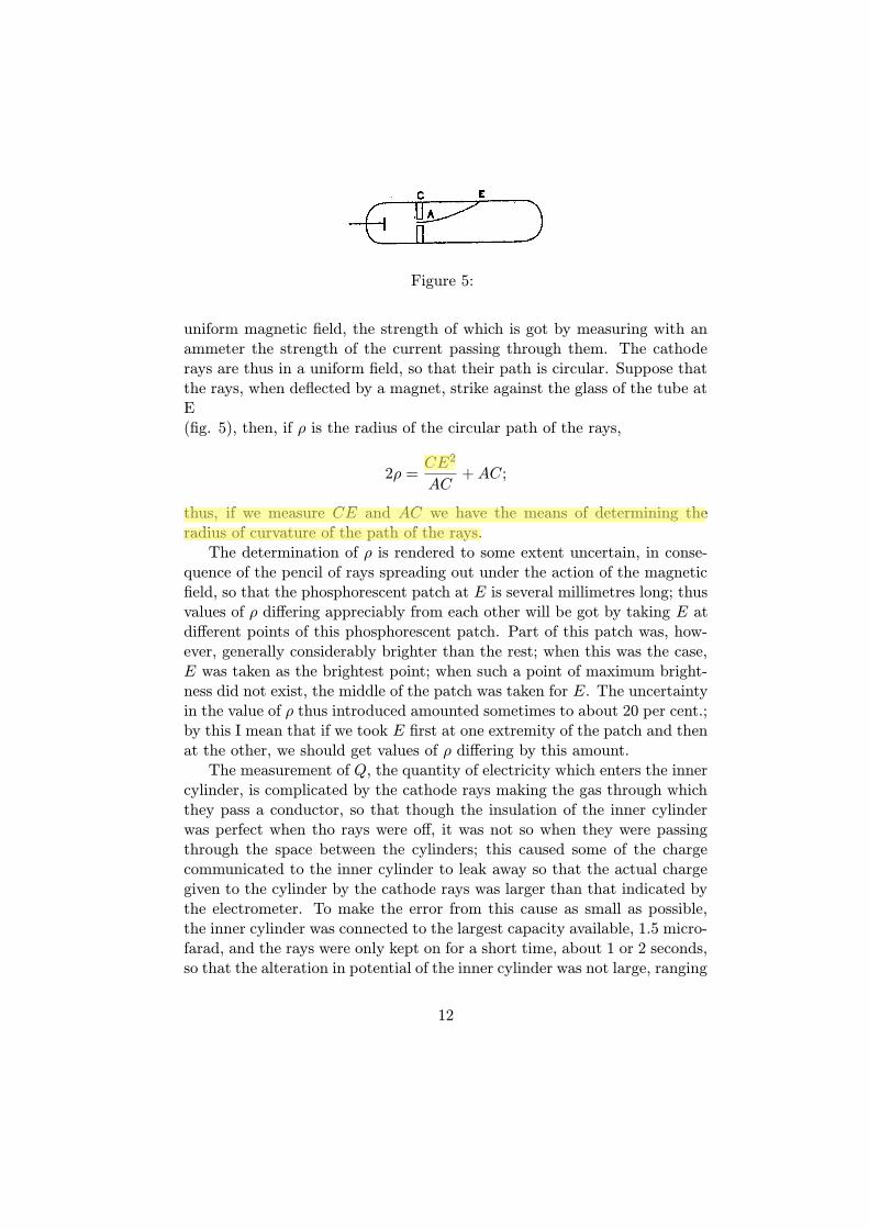
Figure 5:
uniform magnetic field, the strength of which is got by measuring with anammeter the strength of the current passing through them. The cathoderays are thus in a uniform field, so that their path is circular. Suppose thatthe rays, when deflected by a magnet, strike against the glass of the tube atE(fig. 5), then, if ! is the radius of the circular path of the rays,
2! =CE2
AC+AC;
thus, if we measure CE and AC we have the means of determining theradius of curvature of the path of the rays.The determination of ! is rendered to some extent uncertain, in conse-
quence of the pencil of rays spreading out under the action of the magneticfield, so that the phosphorescent patch at E is several millimetres long; thusvalues of ! di"ering appreciably from each other will be got by taking E atdi"erent points of this phosphorescent patch. Part of this patch was, how-ever, generally considerably brighter than the rest; when this was the case,E was taken as the brightest point; when such a point of maximum bright-ness did not exist, the middle of the patch was taken for E. The uncertaintyin the value of ! thus introduced amounted sometimes to about 20 per cent.;by this I mean that if we took E first at one extremity of the patch and thenat the other, we should get values of ! di"ering by this amount.The measurement of Q, the quantity of electricity which enters the inner
cylinder, is complicated by the cathode rays making the gas through whichthey pass a conductor, so that though the insulation of the inner cylinderwas perfect when tho rays were o", it was not so when they were passingthrough the space between the cylinders; this caused some of the chargecommunicated to the inner cylinder to leak away so that the actual chargegiven to the cylinder by the cathode rays was larger than that indicated bythe electrometer. To make the error from this cause as small as possible,the inner cylinder was connected to the largest capacity available, 1.5 micro-farad, and the rays were only kept on for a short time, about 1 or 2 seconds,so that the alteration in potential of the inner cylinder was not large, ranging
12
in the various experiments from about 0.5 to 5 volts. Another reason why itis necessary to limit the duration of the rays to as short a time as possible, isto avoid the correction for the loss of heat from the thermo–electric junctionby conduction along the wires; the rise in temperature of the junction wasof the order 2" C; a series of experiments showed that with the same tubeand the same gaseous pressure Q and W were proportional to each otherwhen the rays were not kept on too long.Tubes of this kind gave satisfactory results, the chief drawback being
that sometimes in consequence of the charging up of the glass of the tube,a secondary discharge started from the cylinder to the walls of the tube,and the cylinders were surrounded by glow; when this glow appeared, thereadings were very irregular; the glow could, however, be got rid of bypumping and letting the tube rest for some time. The results got with thistube are given in the Table under the heading Tube 1.The second type of tube was like that used for photographing the path
of the rays (fig. 4); double cylinders with a thermoelectric junction likethose used in the previous tube were placed in the line of fire of the rays,the inside of the bell–jar was lined with copper gauze connected with theearth. This tube gave very satisfactory results; we were never troubled withany glow round the cylinders, and the readings were most concordant; theonly drawback was that as some of the connexions had to be made withsealing–wax, it was not possible to get the highest exhaustions with thistube, so that the range of pressure for this tube is less than that for tube1. The results got with this tube are given in the Table under the headingTube 2.The third type of tube was similar to the first, except that the openings
in the two cylinders were made very much smaller; in this tube the slits inthe cylinders were replaced by small holes, about 1.5 millim. diameter. Inconsequence of the smallness of the openings, the magnitude of the e"ectswas very much reduced; in order to get measurable results it was necessary toreduce the capacity of the condenser in connexion with the inner cylinder to0.15 microfarad, and to make the galvanometer exceedingly sensitive, as therise in temperature of the thermo–electric junction was in these experimentsonly about 0.5" C on the average. The results obtained in this tube are givenin the Table under the heading Tube 3.The results of a series of measurements with these tubes are given in the
following Table:—
13
Gas Value of I m/e vW/Q
Tube 1.
Air 4.6! 1011 230 0.57! 10!7 4! 109Air 1.8! 1012 350 0.34! 10!7 1! 1010Air 6.1! 1011 230 0.43! 10!7 5.4! 109Air 2.5! 1012 400 0.32! 10!7 1.2! 1010Air 5.5! 1011 230 0.48! 10!7 4.8! 109Air 1! 1012 285 0.4! 10!7 7! 109Air 1! 1012 285 0.4! 10!7 7! 109Hydrogen 6! 1012 205 0.35! 10!7 6! 109Hydrogen 2.1! 1012 460 0.5! 10!7 9.2! 109Carbonic acid 8.4! 1011 260 0.4! 10!7 7.5! 109Carbonic acid 1.47! 1012 340 0.4! 10!7 8.5! 109Carbonic acid 3.0! 1012 480 0.39! 10!7 1.3! 1010
Tube 2.
Air 2.8! 1011 175 0.53! 10!7 3.3! 109Air 2.8! 1011 175 0.53! 10!7 4.1! 109Air 3.5! 1011 181 0.47! 10!7 3.8! 109Hydrogen 2.8! 1011 175 0.53! 10!7 3.3! 109Air 2.5! 1011 160 0.51! 10!7 3.1! 109Carbonic acid 2! 1011 148 0.54! 10!7 2.5! 109Air 1.8! 1011 151 0.63! 10!7 2.3! 109Hydrogen 2.8! 1011 175 0.53! 10!7 3.3! 109Hydrogen 4.4! 1011 201 0.46! 10!7 4.4! 109Air 2.5! 1011 176 0.61! 10!7 2.8! 109Air 4.2! 1011 200 0.48! 10!7 4.1! 109
Tube 3.
Air 2.5! 1011 220 0.9! 10!7 2.4! 109Air 3.5! 1011 225 0.7! 10!7 3.2! 109Hydrogen 3! 1011 250 1.0! 10!7 2.5! 109
14
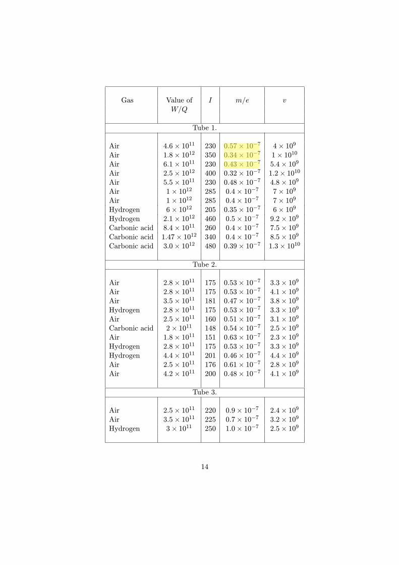
It will be noticed that the value of m/e is considerably greater for Tube3, where the opening is a small hole, than for Tubes 1 and 2, where theopening is a slit of much greater area. I am of opinion that the values ofw/e got from Tubes 1 and 2 are too small, in consequence of the leakagefrom the inner cylinder to the outer by the gas being rendered a conductorby the passage of the cathode rays.It will be seen from these tables that the value of m/e is independent of
the nature of the gas. Thus, fur the first tube the mean for air is 0.40!10!7,for hydrogen 0.42!10!7, and for carbonic acid gas 0.4!10!7; for the secondtube the mean for air is 0.52 ! 10!7, for hydrogen 0.50 ! 10!7, and forcarbonic acid gas 0.54! 10!7.Experiments were tried with electrodes made of iron instead of alu-
minium; this altered the appearance of the discharge and the value of vat the some pressure, the values of m/e were, however, the same in thetwo tubes; the e"ect produced by di"erent metals on the appearance of thedischarge will be described later on.In all the preceding experiments, the cathode rays were first deflected
from the cylinder by a magnet, and it was then found that there was no de-flexion either of the electrometer or the galvanometer, so that the deflexionsobserved were entirely due to the cathode rays; when the glow mentionedpreviously surrounded the cylinders there was a deflexion of the electrometereven when the cathode rays were deflected from the cylinder.Before proceeding to discuss the results of these measurements I shall de-
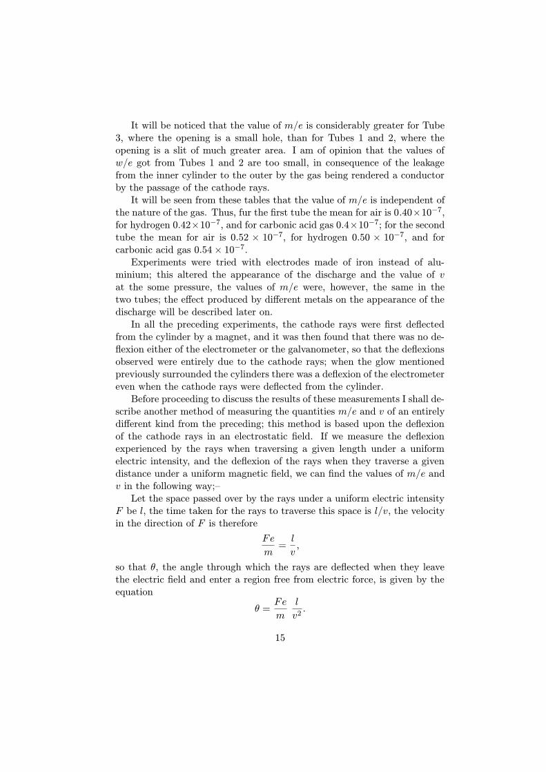
scribe another method of measuring the quantities m/e and v of an entirelydi"erent kind from the preceding; this method is based upon the deflexionof the cathode rays in an electrostatic field. If we measure the deflexionexperienced by the rays when traversing a given length under a uniformelectric intensity, and the deflexion of the rays when they traverse a givendistance under a uniform magnetic field, we can find the values of m/e andv in the following way;–Let the space passed over by the rays under a uniform electric intensity
F be l, the time taken for the rays to traverse this space is l/v, the velocityin the direction of F is therefore
Fe
m=l
v,
so that ", the angle through which the rays are deflected when they leavethe electric field and enter a region free from electric force, is given by theequation
" =Fe
m
l
v2.
15
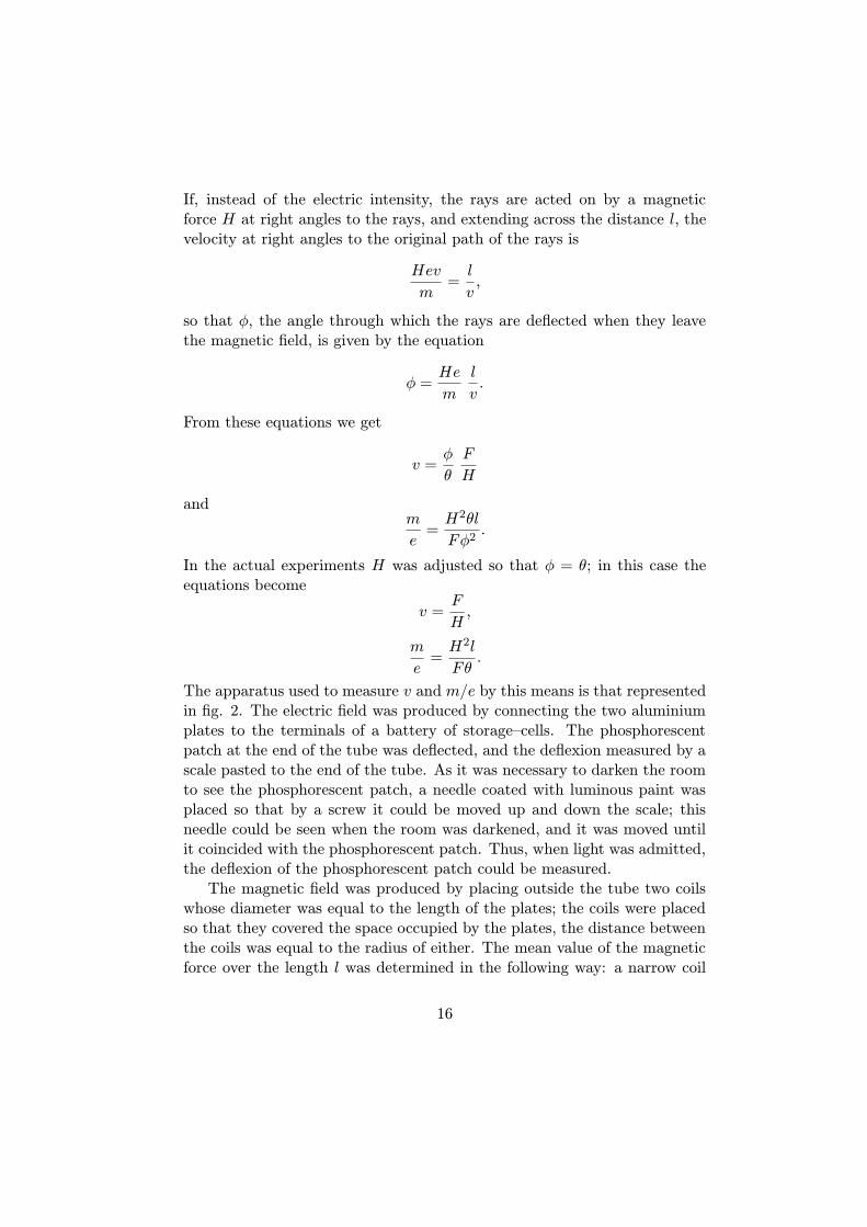
If, instead of the electric intensity, the rays are acted on by a magneticforce H at right angles to the rays, and extending across the distance l, thevelocity at right angles to the original path of the rays is
Hev
m=l
v,
so that #, the angle through which the rays are deflected when they leavethe magnetic field, is given by the equation
# =He
m
l
v.
From these equations we get
v =#
"
F
H
andm
e=H2"l
F#2.
In the actual experiments H was adjusted so that # = "; in this case theequations become
v =F
H,
m
e=H2l
F".
The apparatus used to measure v and m/e by this means is that representedin fig. 2. The electric field was produced by connecting the two aluminiumplates to the terminals of a battery of storage–cells. The phosphorescentpatch at the end of the tube was deflected, and the deflexion measured by ascale pasted to the end of the tube. As it was necessary to darken the roomto see the phosphorescent patch, a needle coated with luminous paint wasplaced so that by a screw it could be moved up and down the scale; thisneedle could be seen when the room was darkened, and it was moved untilit coincided with the phosphorescent patch. Thus, when light was admitted,the deflexion of the phosphorescent patch could be measured.The magnetic field was produced by placing outside the tube two coils
whose diameter was equal to the length of the plates; the coils were placedso that they covered the space occupied by the plates, the distance betweenthe coils was equal to the radius of either. The mean value of the magneticforce over the length l was determined in the following way: a narrow coil
16
C whose length was l, connected with a ballistic galvanometer, was placedbetween the coils; the plane of the windings of C was parallel to the planes ofthe coils; the cross section of the coil was a rectangle 5 cm. by 1 cm. A givencurrent, was sent through the outer coils and the kick a of the galvanometerobserved when this current was reversed. The coil C was then placed atthe centre of two very large coils, so as to be in a field of uniform magneticforce: the current through the large coils was reversed and the kick $ of thegalvanometer again observed; by comparing a and $ we can get the meanvalue of the magnetic force over a length l this was found to be
60! l,
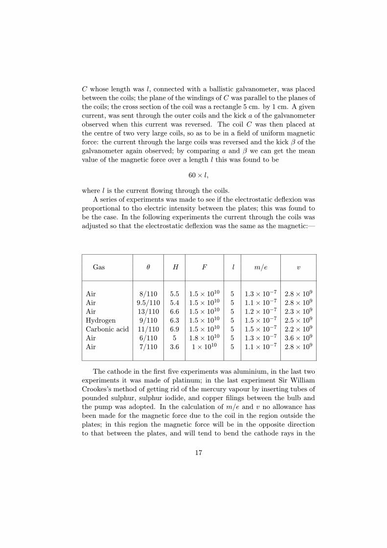
where l is the current flowing through the coils.A series of experiments was made to see if the electrostatic deflexion was
proportional to tho electric intensity between the plates; this was found tobe the case. In the following experiments the current through the coils wasadjusted so that the electrostatic deflexion was the same as the magnetic:—
Gas " H F l m/e v
Air 8/110 5.5 1.5! 1010 5 1.3! 10!7 2.8! 109Air 9.5/110 5.4 1.5! 1010 5 1.1! 10!7 2.8! 109Air 13/110 6.6 1.5! 1010 5 1.2! 10!7 2.3! 109Hydrogen 9/110 6.3 1.5! 1010 5 1.5! 10!7 2.5! 109Carbonic acid 11/110 6.9 1.5! 1010 5 1.5! 10!7 2.2! 109Air 6/110 5 1.8! 1010 5 1.3! 10!7 3.6! 109Air 7/110 3.6 1! 1010 5 1.1! 10!7 2.8! 109
The cathode in the first five experiments was aluminium, in the last twoexperiments it was made of platinum; in the last experiment Sir WilliamCrookes’s method of getting rid of the mercury vapour by inserting tubes ofpounded sulphur, sulphur iodide, and copper filings between the bulb andthe pump was adopted. In the calculation of m/e and v no allowance hasbeen made for the magnetic force due to the coil in the region outside theplates; in this region the magnetic force will be in the opposite directionto that between the plates, and will tend to bend the cathode rays in the
17
opposite direction: thus the e"ective value of H will be smaller than thevalue used in the equations, so that the values of m/e are larger, and thoseof v less than they would be if this correction were applied. This methodof determining the values of m/e and v is much less laborious and probablymore accurate than the former method; it cannot, however, be used over sowide a range of pressures.From these determinations we see that the value of m/e is independent
of the nature of the gas, and that its value 10!7 is very small comparedwith the value 10!4, which is the smallest value of this quantity previouslyknown, and which is the value for the hydrogen ion in electrolysis.Thus for the carriers of the electricity in the cathode rays m/e is very
small compared with its value in electrolysis. The smallness of m/e maybe due to the smallness of m or the largeness of e, or to a combination ofthese two. That the carriers of the charges in the cathode rays are smallcompared with ordinary molecules is shown, I think, by Lenard’s resultsas to the rate at which the brightness of the phosphorescence produced bythese rays diminishes with the length of path travelled by the ray. If weregard this phosphorescence as due to the impact of the charged particles,the distance through which the rays must travel before the phosphorescencefades to a given fraction (say l/e, where e = 2.71) of its original intensity,will be some moderate multiple of the mean free path. Now Lenard foundthat this distance depends solely upon the density of the medium, and notupon its chemical nature or physical state. In air at atmospheric pressurethe distance was about half a centimetre, and this most be comparable withthe mean free path of the carriers through air at atmospheric pressure. Butthe mean free path of the molecules of air is a quantity of quite a di"erentorder. The carrier, then, must be small compared with ordinary molecules.The two fundamental points about these carriers seem to me to be (1)
that these carriers are the same whatever the gas through which the dis-charge passes, (2) that the mean free paths depend upon nothing but thedensity of the medium traversed by these rays.It might be supposed that the independence of the mass of the carriers of
the gas through which the discharge passes was due to the mass concernedbeing the quasi mass which a charged body possesses in virtue of the electricfield set up in its neighbourhood; moving the body involves tho productionof a varying electric field, and, therefore, of a certain amount of energy whichis proportional to the square of the velocity. This causes the charged body tobehave as if its mass were increased by a quantity, which for a charged sphereis 1/5 e2/µa (‘Recent Researches in Electricity and Magnetism’), where e isthe charge and a the radius of the sphere. If we assume that it is this mass
18
which we are concerned with in the cathode rays, since m/e would vary ase/a, it a"ords no clue to the experiment of either of the properties (1 and 2)of these rays. This is not by any means the only objection to this hypothesis,which I only mention to show that it has not been overlooked.The experiment which seems to me to account in the most simple and
straightforward manner for the facts is founded on a view of the constitutionof the chemical elements which has been favourably entertained by manychemists: this view is that the atoms of the di"erent chemical elements aredi"erent aggregations of atoms of the same kind. In the form in which thishypothesis was enunciated by Prout, the atoms of the di"erent elementswere hydrogen atoms; in this precise form the hypothesis is not tenable, butif we substitute for hydrogen some unknown primordial substance X, thereis nothing known which is inconsistent with this hypothesis, which is onethat has been recently supported by Sir Norman Lockyer for reasons derivedfrom the study of the stellar spectra.If, in the very intense electric field in the neighbourhood of the cathode,
the molecules of the gas are dissociated and are split up, not into the or-dinary chemical atoms, but into these primordial atoms, which we shall forbrevity call corpuscles; and if these corpuscles are charged with electricityand projected from the cathode by the electric field, they would behave ex-actly like the cathode rays. They would evidently give a. value of m/e whichis independent of the nature of the gas and its pressure, for the carriers arethe same whatever the gas may be; again, the mean free paths of these cor-puscles would depend solely upon the density of the medium through whichthey pass. For the molecules of tho medium are composed of a number ofsuch corpuscles separated by considerable spaces; now the collision betweena single corpuscle and the molecule will not be between the corpuscles andthe molecule as a whole, but between this corpuscle and the individual cor-puscles which form the molecule; thus the number of collisions the particlemakes as it moves through a crowd of these molecules will be proportional,not to the number of the molecules in the crowd, but to the number of theindividual corpuscles. The mean free path is inversely proportional to thenumber of collisions in unit time, and so is inversely proportional to thenumber of corpuscles in unit volume; now as these corpuscles are all of thesame mass, the number of corpuscles in unit volume will be proportionalto the mass of unit volume, that is the mean free path will be inverselyproportional to the density of the gas. We see, too, that so long as thedistance between neighbouring corpuscles is large compared with the lineardimensions of a corpuscle the mean free path will be independent of the waythey are arranged, provided the number in unit volume remains constant,
19

that is the mean free path will depend only on the density of the mediumtraversed by the corpuscles, and will be independent of its chemical natureand physical state: this from Lenard’s very remarkable measurements ofthe absorption of the cathode rays by various media, must be a propertypossessed by the carriers of the charges in the cathode rays.Thus on this view we have in the cathode rays matter in a new state, a
state in which the subdivision of matter is carried very much further thanin the ordinary gaseous state: a state in which all matter – that is, matterderived from di"erent sources such as hydrogen, oxygen, &c. – is of one andthe same kind; this matter being the substance from which all the chemicalelements are built up.With appliances of ordinary magnitude, the quantity of matter produced
by means of the dissociation at the cathode is so small as to almost topreclude the possibility of any direct chemical investigation of its properties.Thus the coil I used would, I calculate, if kept going uninterruptedly nightand day for a year, produce only about one three–millionth part of a grammeof this substance.The smallness of the value of m/e is, I think, due to the largeness of e as
well as the smallness of m. There seems to me to be some evidence that. thecharges carried by the corpuscles in the atom arc large compared with thosecarried by the ions of an electrolyte. In the molecule of HCl, for example, Ipicture the components of the hydrogen atoms as held together by a greatnumber of tubes of electrostatic force; the components of the chlorine atomare similarly held together, white only one stray tube binds the hydrogenatom to the chlorine atom. The reason for attributing this high charge to theconstituents of the atom is derived from the values of the specific inductivecapacity of gases: we may imagine that the specific inductive capacity of agas is due to the setting in the electric field of the electric doublet formedby the two oppositely electrified atoms which form the molecule of the gas.The measurements of the specific inductive capacity show, however, thatthis is very approximately an additive quantity: that is, that we can assigna certain value to each element, and find the specific inductive capacity ofHCl by adding the value for hydrogen to the value for chlorine; the value ofH2O by adding twice the value for hydrogen to the value for oxygen, and soon. Now the electrical moment of the doublet formed by a positive chargeon one atom of the molecule and a negative charge on the other atom wouldnot be an additive property; it, however, each atom had a definite electricalmoment, and this were large compared with the electrical moment of thetwo atoms in the molecule, then the electrical moment of any compound,and hence its specific inductive capacity, would be an additive property. For
20

the electrical moment of the atom, however, to be large compared with thatof the molecule, the charge on the corpuscles would have to be very largecompared with those on the ion.If we regard the chemical atom as an aggregation of a number of primor-
dial atoms, the problem of finding the configurations of stable equilibriumfor a number of equal particles acting on each other according to some lawof force – whether that of Boscovich, where the force between them is arepulsion when they are separated by less than a certain critical distance,and an attraction when they are separated by a greater distance, or eventhe simpler case of a number of mutually repellent particles held togetherby a central force – is of great interest in connexion with the relation be-tween the properties of an element and its atomic weight. Unfortunatelythe equations which determine the stability of such a collection of particlesincrease so rapidly in complexity with the number of particles that a generalmathematical investigation is scarcely possible. We can, however, obtain agood deal of insight into the general laws which govern such configurationsby the use of models, the simplest of which is the floating magnets of Pro-fessor Mayer. In this model the magnets arrange themselves in equilibriumunder their mutual repulsions and a central attraction caused by the poleof a large magnet placed above the floating magnets.A study of the forms taken by these magnets seems to me to be suggestive
in relation to the periodic law. Mayer showed that when the number offloating magnets did not exceed 5 they arranged themselves at the cornersof a regular polygon – 5 at the corners of a pentagon, 4 at the corners of asquare, and so on. When the number exceeds 5, however, this law no longerholds: thus 6 magnets do not arrange themselves at the corners of a hexagon,but divide into two systems, consisting of 1 in the middle surrounded by 5 atthe corners of a pentagon. For 8 we have two in the inside and 6 outside; thisarrangement in two systems, an inner and an outer, lasts up to 18 magnets.After this we have three systems: an inner, a middle, and an outer; for astill larger number of magnets we have four systems, and so on.Mayor found the arrangement of magnets was as follows: —
where, for example, 1. 6. 10. 12 means an arrangement with one magnetin the middle, then a ring of six, then a ring of ten, and a ring of twelveoutside.Now suppose that a certain property is associated with two magnets
forming a group by themselves; we should have this property with 2 magnets,again with 8 and 9, again with 19 and 20, and again with 34, 35, andso on. If we regard the system of magnets as a model of an atom, thenumber of magnets being proportional to the atomic weight, we should have
21
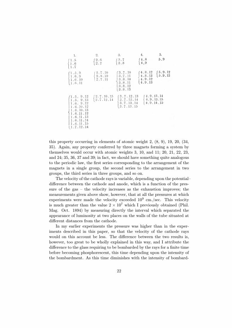
this property occurring in elements of atomic weight 2, (8, 9), 19, 20, (34,35). Again, any property conferred by three magnets forming a system bythemselves would occur with atomic weights 3, 10, and 11; 20, 21, 22, 23,and 24; 35, 36, 37 and 39; in fact, we should have something quite analogousto the periodic law, the first series corresponding to the arrangement of themagnets in a single group, the second series to the arrangement in twogroups, the third series in three groups, and so on.The velocity of the cathode rays is variable, depending upon the potential–
di"erence between the cathode and anode, which is a function of the pres-sure of the gas – the velocity increases as the exhaustion improves; themeasurements given above show, however, that at all the pressures at whichexperiments were made the velocity exceeded 109 cm./sec. This velocityis much greater than the value 2 ! 107 which I previously obtained (Phil.Mag. Oct. 1894) by measuring directly the interval which separated theappearance of luminosity at two places on the walls of the tube situated atdi"erent distances from the cathode.In my earlier experiments the pressure was higher than in the exper-
iments described in this paper, so that the velocity of the cathode rayswould on this account be less. The di"erence between the two results is,however, too great to be wholly explained in this way, and I attribute thedi"erence to the glass requiring to be bombarded by the rays for a finite timebefore becoming phosphorescent, this time depending upon the intensity ofthe bombardment. As this time diminishes with the intensity of bombard-
22
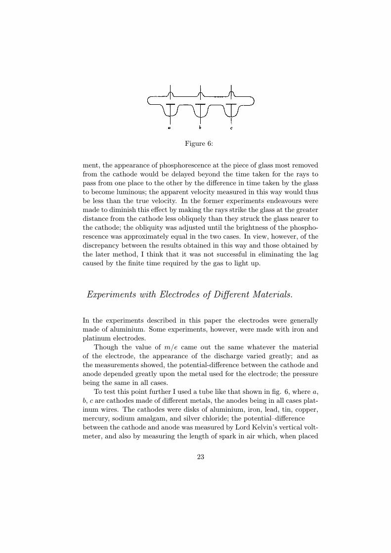
Figure 6:
ment, the appearance of phosphorescence at the piece of glass most removedfrom the cathode would be delayed beyond the time taken for the rays topass from one place to the other by the di"erence in time taken by the glassto become luminous; the apparent velocity measured in this way would thusbe less than the true velocity. In the former experiments endeavours weremade to diminish this e"ect by making the rays strike the glass at the greaterdistance from the cathode less obliquely than they struck the glass nearer tothe cathode; the obliquity was adjusted until the brightness of the phospho-rescence was approximately equal in the two cases. In view, however, of thediscrepancy between the results obtained in this way and those obtained bythe later method, I think that it was not successful in eliminating the lagcaused by the finite time required by the gas to light up.
Experiments with Electrodes of Di!erent Materials.
In the experiments described in this paper the electrodes were generallymade of aluminium. Some experiments, however, were made with iron andplatinum electrodes.Though the value of m/e came out the same whatever the material
of the electrode, the appearance of the discharge varied greatly; and asthe measurements showed, the potential-di"erence between the cathode andanode depended greatly upon the metal used for the electrode; the pressurebeing the same in all cases.To test this point further I used a tube like that shown in fig. 6, where a,
b, c are cathodes made of di"erent metals, the anodes being in all cases plat-inum wires. The cathodes were disks of aluminium, iron, lead, tin, copper,mercury, sodium amalgam, and silver chloride; the potential–di"erencebetween the cathode and anode was measured by Lord Kelvin’s vertical volt-meter, and also by measuring the length of spark in air which, when placed
23
in parallel with the anode and cathode, seemed to allow the discharge to goas often through the spark–gap as through the tube. With this arrangementthe pressures were the same for all the cathodes. The potential–di"erencebetween the anode and cathode and the equivalent spark–length dependedgreatly upon the nature of the cathode. The extent of the variation inpotential may be estimated from the following table: —
Cathode Mean Potential–Di"erencebetween Cathode and Anode
Aluminium 1800 voltsLead 2100 voltsTin 2400 voltsCopper 2600 voltsIron 2900 volts
The potential–di"erence when the cathode was made of sodium amalgamor silver chloride was less even than that of aluminium.The order of many of the metals changed about very capriciously, exper-
iments made at intervals of a few minutes frequently giving quite di"erentresults. From the abrupt way in which these changes take place I am in-clined to think that gas absorbed by the electrode has considerable influenceon the passage of the discharge.I have much pleasure in thanking Mr. Everitt for the assistance he has
given me in the preceding investigation.
Cambridge, Aug. 7, 1897.
24