Embed Size (px)
Citation preview

International Journal of Engineering Sciences & Research
Technology (A Peer Reviewed Online Journal)
Impact Factor: 5.164
IJESRT
Chief Editor Executive Editor
Dr. J.B. Helonde Mr. Somil Mayur Shah
Website: www.ijesrt.com Mail: [email protected] O
IJESRT: 7(12), December, 2018 ISSN: 2277-9655
I X
ISSN: 2277-9655
[Mounika * et al., 7(12): December, 2018] Impact Factor: 5.164
IC™ Value: 3.00 CODEN: IJESS7
http: // www.ijesrt.com© International Journal of Engineering Sciences & Research Technology
[347]
IJESRT is licensed under a Creative Commons Attribution 4.0 International License.
IJESRT INTERNATIONAL JOURNAL OF ENGINEERING SCIENCES & RESEARCH
TECHNOLOGY
DESIGN OF OPTIMUM TORQUE METHOD FOR TRACKING THE MAXIMUM
POWER POINTOF VARIABLE SPEED WIND TURBINE J. Mounika*1& Dr. G. Saraswathi2
*1&2Department of EEE, JNTUK-UCEV, Vizianagaram, Andhra Pradesh, India
DOI: 10.5281/zenodo.2526213
ABSTRACT Optimum torque based maximum power point tracking (MPPT) method is widely used in high power wind
turbines. In this paper a proposed optimum toque method is developed and applied to the wind turbine system.
The diversity of maximum power point tracking methods are developed, all those methods are vary in
implementation, cost, complexity and faster tracking speed, in all of that optimum torque is the more accurate
for the variable speed wind turbines. This optimum torque method involves a generator torque control system
and it is responsible for tracking the reference torque given by MPPT control law. Initially optimum torque
method is developed and then, proportional integral controller is used. Numerical simulations are carried out in
MATLAB platform and the obtained results are of two types, the first one represents the step change in wind
velocity and second represents the turbulent wind velocity.
KEYWORDS: Optimum torque, Maximum power point, Variable speed wind turbine (VSWT), Proportional
integral (PI) controller.
1. INTRODUCTION Wind energy has been one of the fastest growing energy sources in the world. In present days the wind power
generation is increased because of, wind energy is plentiful, renewable, widely distributed& clean. Wind turbine
can capture and convert maximum energy from the wind. Modern wind turbines are more reliable, efficient, cost
effective and the pollution free when compared with the other resources.
Modern wind turbines majorly fall in to two types, horizontal axis and vertical axis. Most large modern wind
turbines are horizontal-axis turbines. A variable speed wind turbine rotational speed must be adjusted when the
wind speed varies but fixed speed wind turbine doesn’t have arrangement of mechanical parts for the adjustable
speed. VSWT have low noise level and increased energy capture when compared to the fixed speed wind
turbine (FSWT). Generally VSWT system uses two-mass model of the drive train shaft.
Reported MPPT method involves different controlling techniques, namely, Tip speed ratio control (TSR),
optimum torque (OT), Perturb and observes (PO) method. These two TSR &PO methods are fail to track the
MPP during parameter variations caused by changes in air density, aging and blade surface contamination. OT
method is suitable for variable speed wind turbines and in this method the energy gain also depends on the level
of turbulence.

ISSN: 2277-9655
[Mounika * et al., 7(12): December, 2018] Impact Factor: 5.164
IC™ Value: 3.00 CODEN: IJESS7
http: // www.ijesrt.com© International Journal of Engineering Sciences & Research Technology
[348]
IJESRT is licensed under a Creative Commons Attribution 4.0 International License.
2. VARIABLE SPEED WIND TURBINE SYSTEM
Fig.1.The configuration of the system considered.
The system considered here consists of a wind turbine with an electric generator as shown in fig.1. The
generator output is connected to the grid through a power electronic converter. Generally, permanent magnet
synchronous generator(PMSG) have advantages of higher efficiency and reliability. PMS generators are
designed with multiple poles which imply that there is no need of gear box which further improves turbine
efficiency and power output.
3. OPTIMAL TORQUE MPPT METHOD As a function of aerodynamic efficiency Cp, the mechanical power Ptof the wind turbine is expressed as
Pt = 1
2ρAv3Cp(λ,β)(1)
λ = wt R/ v
Where
v = wind velocity (m/s)
ρ=air density (kg/m3)
A = swept area of the blade (m2)
wt = rotational speed of the turbine (rpm)
R = radius of the blade(m)
λ= tip speed ratio
β = pitch angle
The basic power equation of the turbine (1) is modified to obtain the aerodynamic torque is given by
Tt = 1
2ρCp (λ)πR5wt/ λ3
For any wind velocity below rated value, the turbine torque that corresponds to the maximum power specified
by
Tto= Kwt2(2)
Eq.(2) is basic for the optimul torque MPPT and is used to set the reference value generator torque Tg , for the
electromagnetic torque. The control law of the conventional optimal torque MPPT is given by
Tg*= Kwg2 (3)
In steady state, under constant wind speed, the OT method ensures that the Tg becomes equal to the Tt and the
system reaches maximum power point. If a positive wind perturbation is occur, the generator speed increases
along the trajectory and reaches new maximum point and generator speed decreases with negative wind
perturbation.

ISSN: 2277-9655
[Mounika * et al., 7(12): December, 2018] Impact Factor: 5.164
IC™ Value: 3.00 CODEN: IJESS7
http: // www.ijesrt.com© International Journal of Engineering Sciences & Research Technology
[349]
IJESRT is licensed under a Creative Commons Attribution 4.0 International License.
Torque equation of PMSG:
Fig.2. PMSG torque control method
Fig.2. represents the torque controlling method of the permament magnet syncronous genrator. This is used for
tracking the reference torque given by the MPPT control technique. The angle between the magnetic axes of thr
rotor and phase coil, is used to convert machine currents into rotor reference frame. From this iq and id values are
identified. For constant torque angle control technique id is to be zero and iq should be proportional to the
torque.The electromagnetic torque equation is
Tg = 3
2 Pφiq = Kt iq
Where
P is the nunber of pole pairs, φ is flux density, iq is quadrature axis current component.
Two mass shaft model:
Fig.3. Two mass drive train model
Fig.3. represents the two-mass model of the shaft, considering separateinertias of the turbine and generator,
connected by a flexible shaft. The state model of the drive train is given by
[w˙tw˙gθ˙sh
] =
[ 0 0 −
Ksh
Jt
0 0Ksh
Jg
1 −1 0 ]
[wtwgθsh
] + [
1
Jt0 0
0 −1
Jg0
0 0 0
] [TtTg0
] (4)
Where Ksh is the stiffness constant, Tg , Jg is the generator torque and inertia, θsh represents the torsional
displacement of the shaft. Tt and Jt represents the turbine torque and inertia.
Starting from initial conditions Tt = Tg = Tt
wt = wg = wgo
By appling laplace to the Eq.3. under intial conditions,
Tg*(s) = 2Kwg0wg(s) = Tg(s)

ISSN: 2277-9655
[Mounika * et al., 7(12): December, 2018] Impact Factor: 5.164
IC™ Value: 3.00 CODEN: IJESS7
http: // www.ijesrt.com© International Journal of Engineering Sciences & Research Technology
[350]
IJESRT is licensed under a Creative Commons Attribution 4.0 International License.
Eq.3. is used in single mass drive train models, when coming with the two mass model a possible realization
would require a aaditional correction componet to the reference generator torque,there by quickening the MPPT
process. This is obtained by augmenting Tg* with the net accelerating torque,coupled with a suitable weight, a, as
From fig. 3, the accelerating torque of the turbine can be expressed as
Tt – Tg = Ta
Ta = Jt dwt
dt + Jg
dwg
dt
By using second and third rows of state space model (4), the above equations can be written as
Ta = Jt d
dt(wg +
Jg
Ksh
d2wg
dt2+
1
Ksh
dTg
dt) + Jg
dwg
dt
Considering zero intial conditions to the above equation Ta can be expressed as
Ta = s ( (Jt +Jg ) + JtJg
Ksh ) wg (s) +
Jt s2
Ksh Tg(s)
From the foregoing discussion on the relative time scales of the shaft speed and generator torque is expressed as
Ta = G1 (s) wg(s) + G2 (s) Tg (s)
The above trnasfer function is improper, because it does not offer a realizable function of Tg*. Hence a function
of H(s) is considered which is third degree polynomial
H(s)= (1 +s
a2ϱ) (1 +
s(ζ)
a1ϱ+
s2
a12ϱ2)
The first term in H(s) ensures a band-limited differentia-tor component, while the second introduces a complex
or real pole-pair, based on the damping coefficient, ζ. A un damped resonator (ζ = 0) is not considered to avoid
internal instability. The proposed control law for the reference generator torque is obtained as
Tg* = Kwg2 – a G(s) wg(s)
G(s) is third degree polynomial which is transfer fuction
1
(1 +s
a2ϱ) (1 +
s(ζ)
a1ϱ+
s2
a12ϱ2)
where
a1=0.463
a2=0.292 and
ϱ=0.0051
ζ = 0.59
4. CONTROLLERS A controller is a device which is used to modify the error signal and prodece a control signal and it modifies the
transient response of the system. There are different controllers are present
i. Proportional controller

ISSN: 2277-9655
[Mounika * et al., 7(12): December, 2018] Impact Factor: 5.164
IC™ Value: 3.00 CODEN: IJESS7
http: // www.ijesrt.com© International Journal of Engineering Sciences & Research Technology
[351]
IJESRT is licensed under a Creative Commons Attribution 4.0 International License.
This controller produces a control signal, proportional to the error signal.
ii. Integral controller
It produces a control signal which is integral of the error signal.
iii. Proportional integral controller
This controller performs both the actions of proportion and integral controllers. It produces a output
signal which is proportional and integral to the error signal.
iv. Proportional derivative controller
It produces a control signal which is proportional plus derivative of the error signal.
v. Proportional integral derivative controller
It performs all three actions of proportional, integral & derivative of the error signal.
PI Controller:
The proportional controller amplifies the error signal and increases the gain of the system. This leads to steady
state tracking accuracy, decrease in sensitivity of the system to parameter variations, disturbence signal rejection
and stability. The main drawback of this controller is that it produces a constant steady state error and negative
impact on the speed of the response, overall stability of the system. By augmenting the optimum torque with the
PI controller will gives the steady state results .
Fig.4. Basic diagram of PI controller
PI controller introduces a zero in yhe system and increases the order by one. This results in a reducing the
steady state error due to integral acontroller. In the figure Kp and Ki are the proportional and integral constants
and corresponding values are taken as 0.1 and 1. A combintion PI and proposed controlling technique are used
to get the desired outputs.
5. SIMULATION RESULTS
Simulation results are presented in two subsections, the first deals with the step change in wind speed and
second deals with turbulent wind speed which is realistic.
Step wind speed change:
A positive step in the wind speed from 9 m/s to 10 m/s is applied at 30 s and the reverse step applied at 70 s. The
corresponding simulation results are shown in the fig.5. Before and after the wind speed steps, both algorithms
ensure that Cp attains its maximum value 0.45 in steady state.
Fig.5.a.Step wind speed

ISSN: 2277-9655
[Mounika * et al., 7(12): December, 2018] Impact Factor: 5.164
IC™ Value: 3.00 CODEN: IJESS7
http: // www.ijesrt.com© International Journal of Engineering Sciences & Research Technology
[352]
IJESRT is licensed under a Creative Commons Attribution 4.0 International License.
Fig.5.b.Turbine speed with OT control law
Fig.5.c.Turbine speed with PI controller
Fig.5.d.Cp profile with OT control law
Fig.5.e. Cp profile with PI controller
Fig.5.f. Electromagnetic torque with OT control law
Fig.5.g. Electromagnetic torque with PI controller
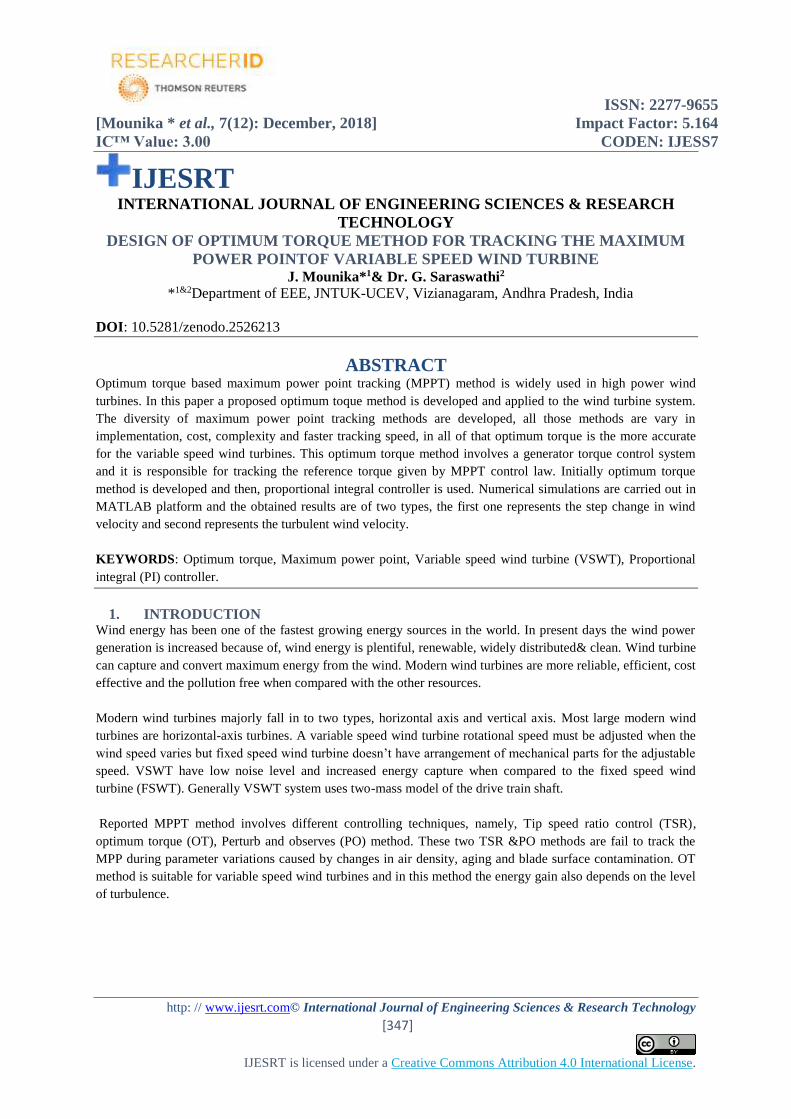
Turbulent wind speed:
To test the performance of these algorithms under realistic turbulent conditions, a wind profile with stochastic
variations around an average wind velocity is generated. Simulation results for the turbulent wind speed are
shown in the fig.6.
ISSN: 2277-9655
[Mounika * et al., 7(12): December, 2018] Impact Factor: 5.164
IC™ Value: 3.00 CODEN: IJESS7
http: // www.ijesrt.com© International Journal of Engineering Sciences & Research Technology
[353]
IJESRT is licensed under a Creative Commons Attribution 4.0 International License.
Fig.6.a. Turbulent wind speed
Fig.6.b. Cp profile
Fig.6.c. Generator wind speed
Fig.6.d. Electromagnetic torque
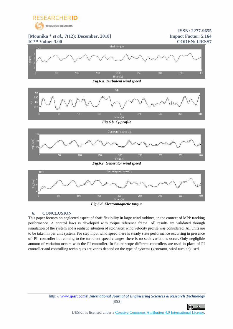
6. CONCLUSION This paper focuses on neglected aspect of shaft flexibility in large wind turbines, in the context of MPP tracking
performance. A control laws is developed with torque reference frame. All results are validated through
simulation of the system and a realistic situation of stochastic wind velocity profile was considered. All units are
to be taken in per unit system. For step input wind speed there is steady state performance occurring in presence
of PI controller but coming to the turbulent speed changes there is no such variations occur. Only negligible
amount of variation occurs with the PI controller. In future scope different controllers are used in place of PI
controller and controlling techniques are varies depend on the type of systems (generator, wind turbine) used.
ISSN: 2277-9655
[Mounika * et al., 7(12): December, 2018] Impact Factor: 5.164
IC™ Value: 3.00 CODEN: IJESS7
http: // www.ijesrt.com© International Journal of Engineering Sciences & Research Technology
[354]
IJESRT is licensed under a Creative Commons Attribution 4.0 International License.
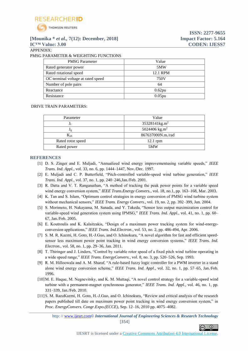
APPENDIX:
PMSG PARAMETER & WEIGHTING FUNCTIONS
PMSG Parameter Value
Rated generator power 5MW
Rated rotational speed 12.1 RPM
OC terminal voltage at rated speed 750V
Number of pole pairs 64
Reactance 0.62pu
Resistance 0.05pu
DRIVE TRAIN PARAMETERS:
Parameter Value
Jt 35328141kg.m2
Jg 5024406 kg.m2
Ksh 867637000N.m./rad
Rated rotor speed 12.1 rpm
Rated power 5MW
REFERENCES
[1] D. S. Zinger and E. Muljadi, “Annualized wind energy improvementusing variable speeds,” IEEE
Trans. Ind. Appl., vol. 33, no. 6, pp. 1444–1447, Nov./Dec. 1997.
[2] E. Muljadi and C. P. Butterfield, “Pitch-controlled variable-speed wind turbine generation,” IEEE
Trans. Ind. Appl., vol. 37, no. 1, pp. 240–246,Jan./Feb. 2001.
[3] R. Datta and V. T. Ranganathan, “A method of tracking the peak power points for a variable speed
wind energy conversion system,” IEEE Trans.Energy Convers., vol. 18, no.1, pp. 163–168, Mar. 2003.
[4] K. Tan and S. Islam, “Optimum control strategies in energy conversion of PMSG wind turbine system
without mechanical sensors,” IEEE Trans. Energy Convers., vol. 19, no. 2, pp. 392–399, Jun. 2004.
[5] S. Morimoto, H. Nakayama, M. Sanada, and Y. Takeda, “Sensor less output maximization control for
variable-speed wind generation system using IPMSG,” IEEE Trans. Ind. Appl., vol. 41, no. 1, pp. 60–
67, Jan./Feb. 2005.
[6] E. Koutroulis and K. Kalaitzakis, “Design of a maximum power tracking system for wind-energy-
conversion applications,” IEEE Trans. Ind.Electron., vol. 53, no. 2, pp. 486-494, Apr. 2006.
[7] S. M. R. Kazmi, H. Goto, H.-J.Guo, and O. Ichinokura, “A novel algorithm for fast and efficient speed-
sensor less maximum power point tracking in wind energy conversion systems,” IEEE Trans. Ind.
Electron., vol. 58, no. 1, pp. 29–36, Jan. 2011.
[8] T. Thiringer and J. Linders, “Control by variable rotor speed of a fixed pitch wind turbine operating in
a wide speed range,” IEEE Trans. EnergyConvers., vol. 8, no. 3, pp. 520–526, Sep. 1993.
[9] R. M. Hilloowala and A. M. Sharaf, “A rule-based fuzzy logic controller for a PWM inverter in a stand
alone wind energy conversion scheme,” IEEE Trans. Ind. Appl., vol. 32, no. 1, pp. 57–65, Jan./Feb.
1996.
[10] M. E. Haque, M. Negnevitsky, and K. M. Muttaqi, “A novel control strategy for a variable-speed wind
turbine with a permanent-magnet synchronous generator,” IEEE Trans. Ind. Appl., vol. 46, no. 1, pp.
331–339, Jan./Feb. 2010.
[11] S. M. RazaKazmi, H. Goto, H.-J.Guo, and O. Ichinokura, “Review and critical analysis of the research
papers published till date on maximum power point tracking in wind energy conversion system,” in
Proc. EnergyConvers. Congr.Expo.(ECCE), Sep. 12–16, 2010 pp. 4075–4082.

ISSN: 2277-9655
[Mounika * et al., 7(12): December, 2018] Impact Factor: 5.164
IC™ Value: 3.00 CODEN: IJESS7
http: // www.ijesrt.com© International Journal of Engineering Sciences & Research Technology
[355]
IJESRT is licensed under a Creative Commons Attribution 4.0 International License.
[12] Z. M. Dalala, Z. U. Zahid, W. Yu, Y. Cho, and J.-S.Lai, “Design and analysis of an MPPT technique
for small-scale wind energy conversion systems,” IEEE Trans. Energy Convers., vol. 28, no. 3, pp.
756–767, Sep. 2013.
[13] K. E. Johnson, L. J. Fingersh, M. J. Balas, and L. Y. Pao, “Methods for increasing region 2 power
capture on a variable-speed wind turbine,” J.Sol. Energy Eng., vol. 126, no. 4, pp. 1092–1100, 2004.
[14] L. J. Fingersh and P. W. Carlin, “Results from the NREL variable-speed test bed,” in Nat. Renew.
Energy Lab., Golden, CO, USA, Rep. NREL/CP- 500-23811, 1998.
[15] W. E. Leithead and B. Connor, “Control of variable speed wind turbines: Design task,” Int. J. Control,
vol. 73, no. 13, pp. 1189–1212, 2000.
[16] K.-H. Kim, T. L. Van, D.-C.Lee, S.-H.Song, and E.-H. Kim, “Maximum output power tracking control
in variable-speed wind turbine systems considering rotor inertial power,” IEEE Trans. Ind. Electron.,
vol. 60, no. 8, pp. 3207–3217, Aug. 2013.
[17] B. Boukhezzar and H. Siguerdidjane, “Nonlinear control of a variablespeedwind turbine using a two-
mass model,” IEEE Energy Convers., vol. 26, no. 1, pp. 149–162, Mar. 2011.
[18] I. Girsang, J. Dhupia, E. Muljadi, M. Singh, and L. Pao, “Gearbox and drivetrain models to study
dynamic effects of modern wind turbines,” in Proc. IEEE Energy Convers. Congr.Expo., 2013, pp.
874–881.
[19] L. Soderlund, J.-T. Eriksson, J. Salonen, H. Vihriala, and R. Perala, “A permanent-magnet generator
for wind power applications,” IEEE Trans.Magn., vol. 32, no. 4, pp. 2389–2392, Jul. 1996.
[20] J. Y. Chen, C. V. Nayar, and X. Longya, “Design and finite-element analysis of an outer-rotor
permanent-magnet generator for directly coupled wind turbines,” IEEE Trans. Magn., vol. 36, no. 5,
pp. 3802–3809, Sep. 2000.
[21] I. Munteanu, A. I. Bratcu, and E. Ceanga, “Wind turbulence used as searching signal for MPPT in
variable-speed wind energy conversion systems,” Renew. Energy, vol. 34, no. 1, pp. 322–327, Jan.
2009, doi: 10.1016/j.renene.2008.03.001.
[22] C. Nichita, D. Luca, B. Dakyo, and E. Ceanga, “Large band simulationof the wind speed for real time
wind turbine simulators,” IEEE Trans.Energy Convers., vol. 17, no. 4, pp. 523–529, Dec. 2002.
[23] R. Krishnan, Permanent Magnet Synchronous and Brushless DC Motor Drives. Boca Raton, FL, USA:
CRC Press, 2009.
[24] M. Chinchilla, S. Arnaltes, and J. C. Burgos, “Control of permanent magnet generators applied to
variable-speed wind-energy systems connected to the grid,” IEEE Trans. Energy Convers., vol. 21, no.
1, pp. 130–135, Mar. 2006.
[25] W. Leonhard, Control of Electrical Drives. New York, NY, USA: Springer, 1997.
[26] S. Butterfield, W. Musial, and G. Scott, “Definition of a 5-MW reference wind turbine for offshore
system development,” Nat. Renew.Energy Lab., Golden, CO, USA, Rep. NREL/TP-500-38060, 2009.
[27] A. Steinberg and H. Holttinen, “Analysing failure statistics of wind turbines in Finland,” in Proc. Eur.
Wind Energy Conf., Apr. 2010, pp. 20–23.
[28] J. F. Manwell, J. G. McGowan, and A. L. Rogers, Wind Energy Explained: Theory, Design and
Application, West Sussex, England: John Wiley & Sons, 2002
[29] H. Joanne, "An adaptive control algorithm for maximum power point tracking for wind energy
conversion systems". Ontario, Canada. Dec. 2008
[30] F.-S. dos Reis, K. Tan, and S. Islam, “Using pfc for harmonic mitigation inwind turbine energy
conversion systems,” IEEE Industrial Electronics SocietyConference, pp. 3100–3105, November 2004.
[31] J. Marques, H. Pinheiro, H. Grundling, J. Pinheiro, and H. Hey, “A surveyon variable-speed wind
turbine system,” Proceedings of Brazilian conference ofelectronics of power, vol. 1, pp. 732 – 738,
2003.

ISSN: 2277-9655
[Mounika * et al., 7(12): December, 2018] Impact Factor: 5.164
IC™ Value: 3.00 CODEN: IJESS7
http: // www.ijesrt.com© International Journal of Engineering Sciences & Research Technology
[356]
IJESRT is licensed under a Creative Commons Attribution 4.0 International License.
[32] S. M. RazaKazmi, H. Goto, H.-J.Guo, and O. Ichinokura, “Review andcritical analysis of the research
papers published till date on maximumpower point tracking in wind energy conversion system,” in
Proc. EnergyConvers. Congr.Expo.(ECCE), Sep. 12–16, 2010 pp. 4075–4082.
CITE AN ARTICLE
Mounika, J., & Saraswathi, G., Dr. (2018). DESIGN OF OPTIMUM TORQUE METHOD FOR
TRACKING THE MAXIMUM POWER POINTOF VARIABLE SPEED WIND
TURBINE. INTERNATIONAL JOURNAL OF ENGINEERING SCIENCES & RESEARCH
TECHNOLOGY, 7(12), 347-356.
![JESRT: 9(5), May, 2020 ISSN: 2277-9655 I International ... /Archive-2020/May-2020/2.pdf · ISSN: 2277-9655 [Kabeyi et al., 9(5): May, 2020] Impact Factor: 5.164 IC™ Value: 3.00](https://img.dokumen.tips/doc/110x75/5f0882f77e708231d4225fc8/jesrt-95-may-2020-issn-2277-9655-i-international-archive-2020may-20202pdf.jpg)


![JESRT: 8(1), January, 2019 ISSN: 2277-9655 I nternational …ijesrt.com/issues /Archive-2019/january-2019/38.pdf · proves potential in the management of urolithiasis [6, 7]. Antioxidants](https://img.dokumen.tips/doc/110x75/5caea69188c99323378c8bd8/jesrt-81-january-2019-issn-2277-9655-i-nternational-archive-2019january-201938pdf.jpg)


![ISSN: 2277-9655 (I2OR), Publication Impact Factor: 3.785 ... /Archive-2016/January-2016/82.pdf · [Adari, 5(1): January, 2016] ISSN: 2277-9655 (I2OR), Publication Impact Factor: 3.785](https://img.dokumen.tips/doc/110x75/5b515b5b7f8b9a6b118bf4f6/issn-2277-9655-i2or-publication-impact-factor-3785-archive-2016january-201682pdf.jpg)