Embed Size (px)
DESCRIPTION
JBL line array solution for high performance fixed installation applications. Combines world-class PD700 Precision Directivity and VerTec® speaker technologies. White Paper v2.
Citation preview
White Paper v.2
JBL Variable Line Array Technology
Achieving Optimum Line Array Performance Through High Performance Horn-Loaded Modular Design
by Brad Ricks

1
Introduction Line arrays have become an attractive solution for stadiums, arenas and other large spaces due to their ability to provide precise vertical pattern control and very high sound pressure levels. Within their coverage pattern, line array solutions exhibit relatively smooth coverage by coherently combining the individual elements and suppressing detrimental lobes.
The JBL VLA SERIES (Variable Line Array) was developed to take advantage of the beneficial aspects of line array solutions while improving important performance characteristics that make them better suited for many large-scale reinforcement projects.
Figure 1. JBL VLA901H System
2
Background Line arrays were originally developed as a tour product for stage events. For this application they needed to be relatively small with a relatively wide horizontal coverage pattern. The smaller size minimizes weight, reduces truck space, and is visually less obtrusive when flown. The wide horizontal coverage pattern allows for more seats to be covered by fewer arrays, making them great for touring and some fixed installations.
The larger fixed installations however, have different priorities and some of the features describing touring line arrays may not be as important. Solutions with narrower coverage and sharper polar cut-offs provide the ability to keep more energy off adjacent walls or other areas which may create objectionable reflections. They also have the potential to reduce the overlap between adjacent arrays. For many years, this has been an objective in the use of traditional loudspeakers with large waveguides and controlled horizontal coverage.
Late signal arrivals to the listener position, whether from reflected energy or adjacent arrays, can have an adverse effect on speech intelligibility. The later and stronger the signal arrival, the more it can degrade speech intelligibility [JBL Professional Technical Note, Volume 1, Number 26, “Speech Intelligibility”].
As an example, in a small room where two arrays are flown left and right of the stage, the application is fairly tolerant of a wide-coverage line array. Indeed the wide coverage may be required so that the room can be evenly covered with just two arrays. Signal arrival times are relatively close together (<30 ms) and sufficiently down in level to where their influence is not objectionable. Speech intelligibility is high and music has good clarity.
As the room size scales up, the signal arrival times at the listener position become more spread out over time and typically the reverberation time of the room becomes longer. This trend continues in venue sizes all the way up through large arenas and indoor stadiums, where RT60s can reach 4 to 5 seconds in the mid frequency bands and 7 to 9 seconds in the lower octave bands. At some point, signal arrivals from adjacent arrays become late enough and high enough in level to where speech intelligibility suffers. The JBL VLA SERIES was developed primarily for large venues where high sound pressure levels and precise pattern control are required to provide best possible speech intelligibility and sound pressure levels. The JBL VLA SERIES seeks to synthesize the vertical pattern control and high SPL capabilities of the line array speakers such as JBL VerTec® and the effective horizontal pattern control and sensitivity of large waveguide-based loudspeakers such as the JBL Precision Directivity® PD700.
Objectives The JBL VLA SERIES was created with two primary objectives in mind:
1. Improved horizontal pattern control,
2. Increased power output capabilities.
To accomplish this, the JBL VLA SERIES array loudspeaker systems have two very important features:
3
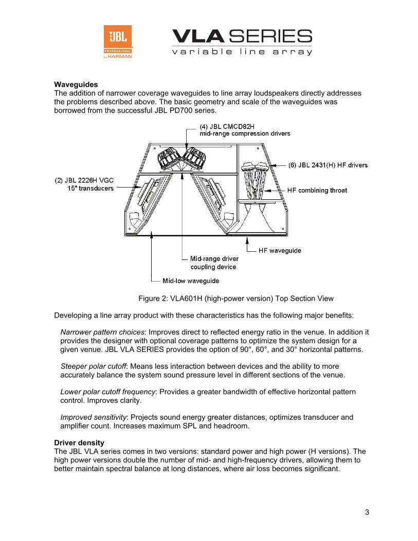
Waveguides The addition of narrower coverage waveguides to line array loudspeakers directly addresses the problems described above. The basic geometry and scale of the waveguides was borrowed from the successful JBL PD700 series.
Figure 2: VLA601H (high-power version) Top Section View
Developing a line array product with these characteristics has the following major benefits:
Narrower pattern choices: Improves direct to reflected energy ratio in the venue. In addition it provides the designer with optional coverage patterns to optimize the system design for a given venue. JBL VLA SERIES provides the option of 90°, 60°, and 30° horizontal patterns.
Steeper polar cutoff: Means less interaction between devices and the ability to more accurately balance the system sound pressure level in different sections of the venue.
Lower polar cutoff frequency: Provides a greater bandwidth of effective horizontal pattern control. Improves clarity.
Improved sensitivity: Projects sound energy greater distances, optimizes transducer and amplifier count. Increases maximum SPL and headroom.
Driver density The JBL VLA series comes in two versions: standard power and high power (H versions). The high power versions double the number of mid- and high-frequency drivers, allowing them to better maintain spectral balance at long distances, where air loss becomes significant.
4
Technology Used in JBL VLA Series Line array technology JBL VLA SERIES arrays utilize line array technology. Fundamentals of line arrays are well documented in the literature [Ureda, Mark, J. AES Vol 52, No. 5, May 2004]. Essentially, line arrays are curved arrays where the spacing of sources is less than a wavelength (Other means may be used to “flatten” the wavefront to allow it to combine with adjacent sources). This allows coherent summation of the drivers and suppresses the development of side lobes – in this case, above and below the array.
Line arrays are shaped so the curvature of the array is less for the long-throw section of the array and increases proportionately for the short throw section of the array. In theory, the curvature of an array should be inversely proportional to its throw distance. Arrays of this type are termed “progressive arrays” [Ureda].
Alternatively, gain shading may be used with a constant curvature array. This works better when the line array element has some directivity of its own which, given the size of the waveguides, the JBL VLA SERIES provides. In practice, some combination of a shaped progressive array and gain shading is typically used.
Transducers The JBL VLA SERIES uses two JBL 2226H VGC Vented Gap Cooled 15” transducers for low frequency, each of which can handle 1000W AES [JBL Professional Technical Note Volume 1, Number 18]. The midrange section features the patented technology of the CMCD82H 200 mm (8 in) cone midrange compression driver with dual 75 mm (3 in) voice coils [JBL Professional Technical Note Volume 1, Number 30]. The CMCD82H utilizes a driver/phasing plug assembly that provides high output with low distortion. These advanced drivers are capable of handling 350W AES each. For the high frequencies, three to six JBL 2431H aluminum diaphragm drivers are used. The compact design of these drivers allows them to be packed tightly together to achieve higher energy density.
The transducers used in the VLA product line are of the same family as is used in PD700-series, PD5000-series, and AM7000-series. The waveguides also share similar topologies. This combines to give the family similar sonic properties. A few examples of systems that use loudspeakers from these related series will be described below.
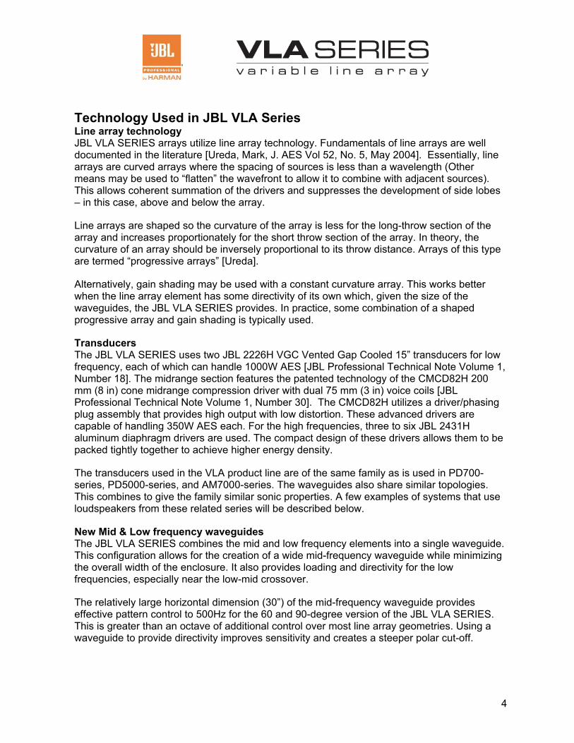
New Mid & Low frequency waveguides The JBL VLA SERIES combines the mid and low frequency elements into a single waveguide. This configuration allows for the creation of a wide mid-frequency waveguide while minimizing the overall width of the enclosure. It also provides loading and directivity for the low frequencies, especially near the low-mid crossover.
The relatively large horizontal dimension (30”) of the mid-frequency waveguide provides effective pattern control to 500Hz for the 60 and 90-degree version of the JBL VLA SERIES. This is greater than an octave of additional control over most line array geometries. Using a waveguide to provide directivity improves sensitivity and creates a steeper polar cut-off.
5
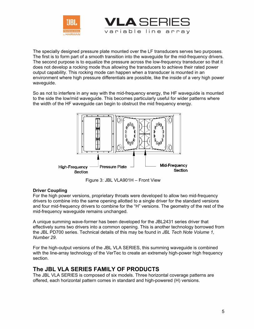
The specially designed pressure plate mounted over the LF transducers serves two purposes. The first is to form part of a smooth transition into the waveguide for the mid-frequency drivers. The second purpose is to equalize the pressure across the low-frequency transducer so that it does not develop a rocking mode thus allowing the transducers to achieve their rated power output capability. This rocking mode can happen when a transducer is mounted in an environment where high pressure differentials are possible, like the inside of a very high power waveguide.
So as not to interfere in any way with the mid-frequency energy, the HF waveguide is mounted to the side the low/mid waveguide. This becomes particularly useful for wider patterns where the width of the HF waveguide can begin to obstruct the mid frequency energy.
Figure 3: JBL VLA901H – Front View
Driver Coupling For the high power versions, proprietary throats were developed to allow two mid-frequency drivers to combine into the same opening allotted to a single driver for the standard versions and four mid-frequency drivers to combine for the “H” versions. The geometry of the rest of the mid-frequency waveguide remains unchanged.
A unique summing wave-former has been developed for the JBL2431 series driver that effectively sums two drivers into a common opening. This is another technology borrowed from the JBL PD700 series. Technical details of this may be found in JBL Tech Note Volume 1, Number 29.
For the high-output versions of the JBL VLA SERIES, this summing waveguide is combined with the line-array technology of the VerTec to create an extremely high-power high frequency section.
The JBL VLA SERIES FAMILY OF PRODUCTS The JBL VLA SERIES is composed of six models. Three horizontal coverage patterns are offered, each horizontal pattern comes in standard and high-powered (H) versions.
6
Table 1: VLA SERIES Family
Model
Horizontal Coverage
Max SPL LF, MF, HF
(dB SPL Cont. Avg.)
Height
Width
Depth
Weight
JBL VLA 301 30° 132,139,144 21” 53.2” 54.5” 309 lbs. JBL VLA 601 60° 132,137,141 21” 53.2” 30.4” 225 lbs. JBL VLA 901 90° 131,134,139 21” 53.2” 25.2” 211 lbs. JBL VLA 301H 30° 132,142,146 21” 53.2” 54.5” 342 lbs. JBL VLA 601H 60° 132,141,144 21” 53.2” 30.4” 256 lbs. JBL VLA 901H 90° 131,139,142 21” 53.2” 25.2” 241 lbs.
* Vertical coverage varies with array size and configuration.
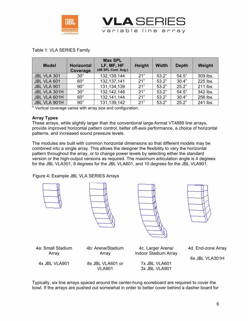
Array Types These arrays, while slightly larger than the conventional large-format VT4889 line arrays, provide improved horizontal pattern control, better off-axis performance, a choice of horizontal patterns, and increased sound pressure levels.
The modules are built with common horizontal dimensions so that different models may be combined into a single array. This allows the designer the flexibility to vary the horizontal pattern throughout the array, or to change power levels by selecting either the standard version or the high-output versions as required. The maximum articulation angle is 4 degrees for the JBL VLA301, 8 degrees for the JBL VLA601, and 10 degrees for the JBL VLA901.
Applications:
Arena Systems
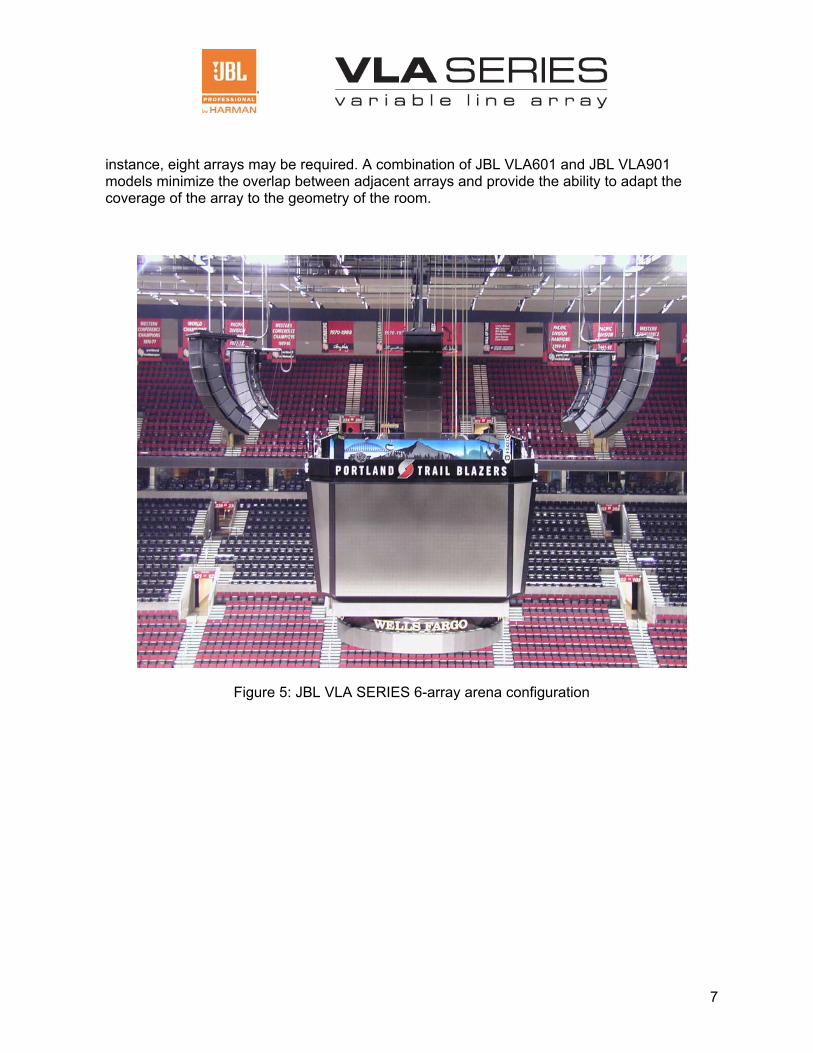
Typically, six line arrays spaced around the center-hung scoreboard are required to cover the bowl. If the arrays are pushed out somewhat in order to better cover behind a dasher board for
4d. End-zone Array
6x JBL VLA301H
4c. Larger Arena/ Indoor Stadium Array
7x JBL VLA601 3x JBL VLA901
4a: Small Stadium Array
4x JBL VLA901
4b: Arena/Stadium Array
8x JBL VLA601 or
VLA901
Figure 4: Example JBL VLA SERIES Arrays
7
instance, eight arrays may be required. A combination of JBL VLA601 and JBL VLA901 models minimize the overlap between adjacent arrays and provide the ability to adapt the coverage of the array to the geometry of the room.
Figure 5: JBL VLA SERIES 6-array arena configuration
8
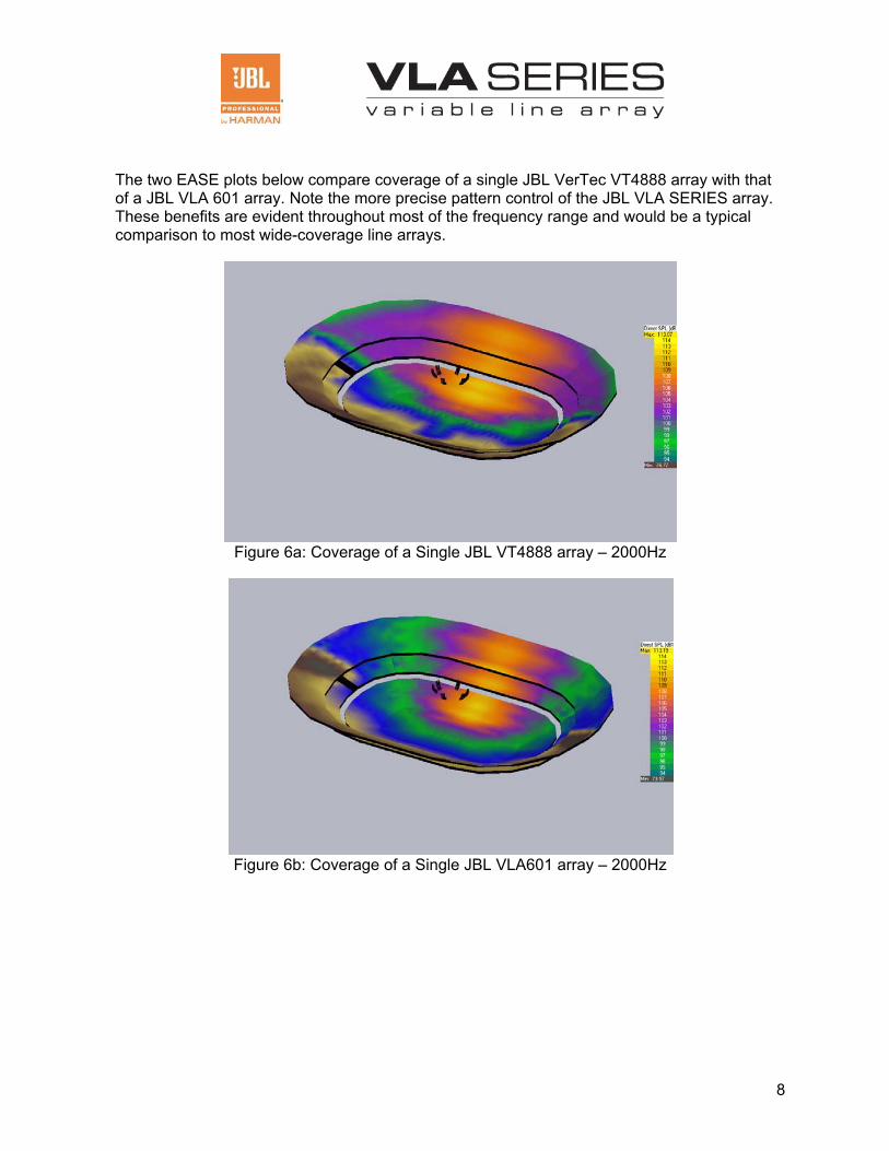
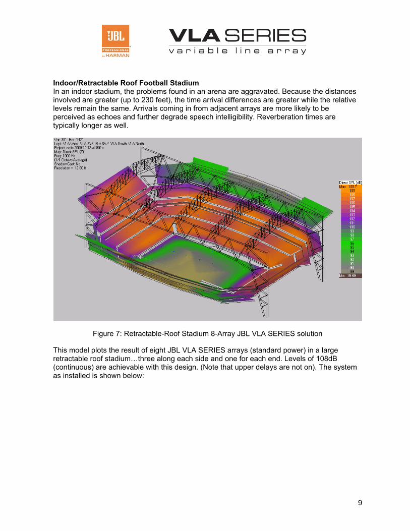
The two EASE plots below compare coverage of a single JBL VerTec VT4888 array with that of a JBL VLA 601 array. Note the more precise pattern control of the JBL VLA SERIES array. These benefits are evident throughout most of the frequency range and would be a typical comparison to most wide-coverage line arrays.
Figure 6a: Coverage of a Single JBL VT4888 array – 2000Hz
Figure 6b: Coverage of a Single JBL VLA601 array – 2000Hz
9
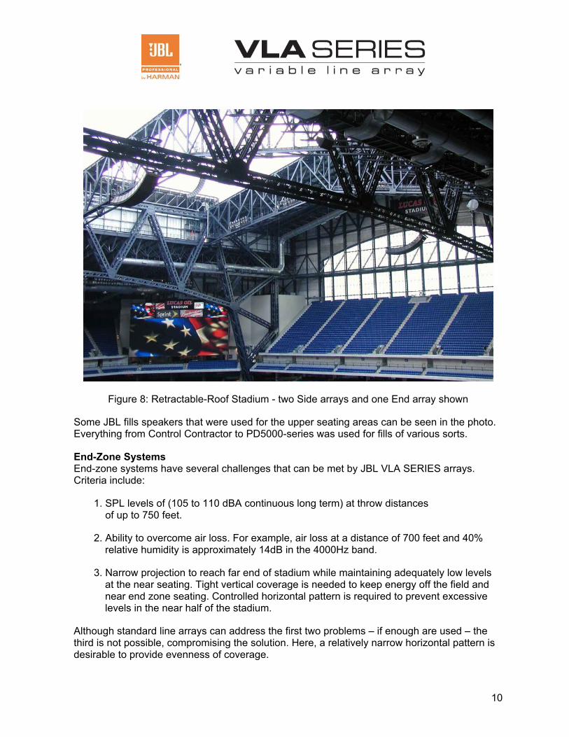
Indoor/Retractable Roof Football Stadium In an indoor stadium, the problems found in an arena are aggravated. Because the distances involved are greater (up to 230 feet), the time arrival differences are greater while the relative levels remain the same. Arrivals coming in from adjacent arrays are more likely to be perceived as echoes and further degrade speech intelligibility. Reverberation times are typically longer as well.
Figure 7: Retractable-Roof Stadium 8-Array JBL VLA SERIES solution
This model plots the result of eight JBL VLA SERIES arrays (standard power) in a large retractable roof stadium…three along each side and one for each end. Levels of 108dB (continuous) are achievable with this design. (Note that upper delays are not on). The system as installed is shown below:
10
Figure 8: Retractable-Roof Stadium - two Side arrays and one End array shown
Some JBL fills speakers that were used for the upper seating areas can be seen in the photo. Everything from Control Contractor to PD5000-series was used for fills of various sorts.
End-Zone Systems End-zone systems have several challenges that can be met by JBL VLA SERIES arrays. Criteria include:
1. SPL levels of (105 to 110 dBA continuous long term) at throw distances of up to 750 feet.
2. Ability to overcome air loss. For example, air loss at a distance of 700 feet and 40% relative humidity is approximately 14dB in the 4000Hz band.
3. Narrow projection to reach far end of stadium while maintaining adequately low levels at the near seating. Tight vertical coverage is needed to keep energy off the field and near end zone seating. Controlled horizontal pattern is required to prevent excessive levels in the near half of the stadium.
Although standard line arrays can address the first two problems – if enough are used – the third is not possible, compromising the solution. Here, a relatively narrow horizontal pattern is desirable to provide evenness of coverage.

11
Successful end-zone designs come in three main flavors:
1) Two VLA601H arrays either side of video board. Typically these are 6 deep but can be less, sometimes driven by height of existing space. This configuration is used for medium to large college football where budget is a consideration and mounting locations are easiest or already exist on either side of the video/scoreboard. In the picture below, a 6-deep VLA array is located on either side of the video board.
Figure 9: JBL VLA SERIES Stadium Split System End-zone Configuration
Note the JBL PD700-series speakers used for out fill. PD5212 speakers are also used directly below the arrays for the near stands. With the VLA arrays doing the heavy lifting, these high powered defined coverage boxes can effectively provide coverage to the border areas.
12
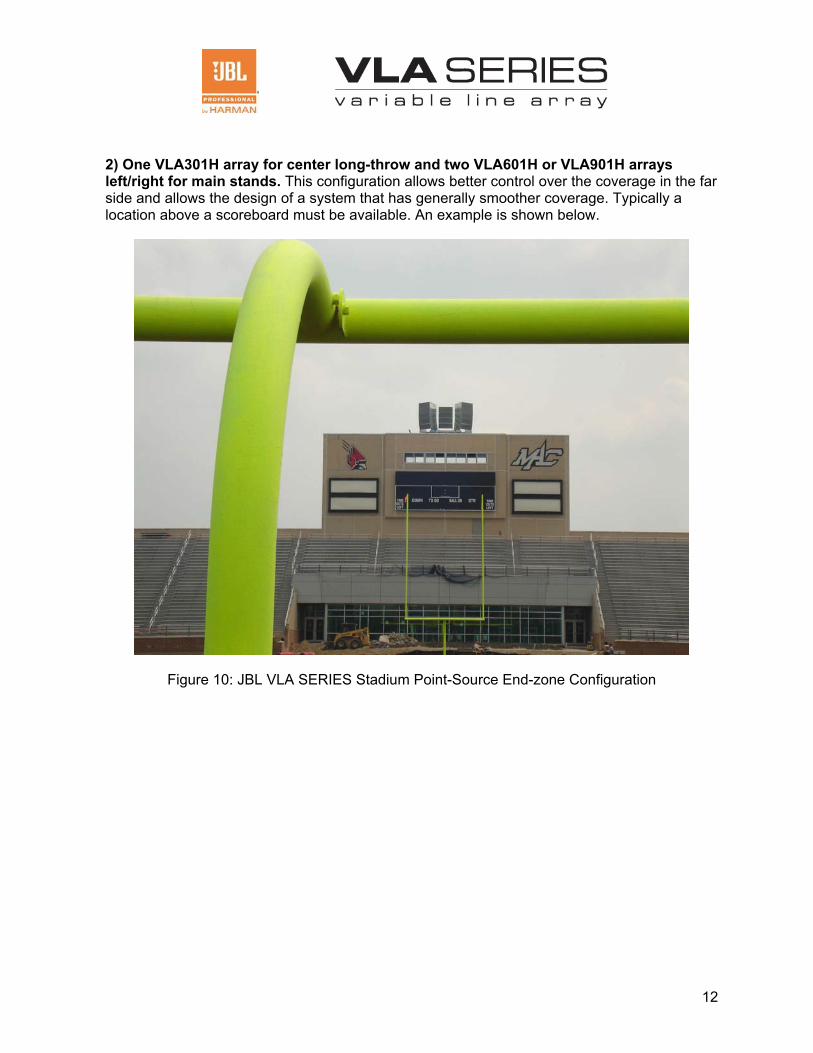
2) One VLA301H array for center long-throw and two VLA601H or VLA901H arrays left/right for main stands. This configuration allows better control over the coverage in the far side and allows the design of a system that has generally smoother coverage. Typically a location above a scoreboard must be available. An example is shown below.
Figure 10: JBL VLA SERIES Stadium Point-Source End-zone Configuration
13
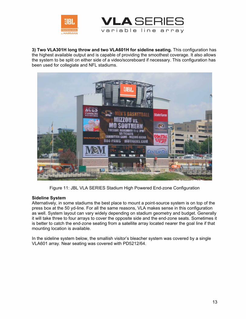
3) Two VLA301H long throw and two VLA601H for sideline seating. This configuration has the highest available output and is capable of providing the smoothest coverage. It also allows the system to be split on either side of a video/scoreboard if necessary. This configuration has been used for collegiate and NFL stadiums.
Figure 11: JBL VLA SERIES Stadium High Powered End-zone Configuration
Sideline System Alternatively, in some stadiums the best place to mount a point-source system is on top of the press box at the 50 yd-line. For all the same reasons, VLA makes sense in this configuration as well. System layout can vary widely depending on stadium geometry and budget. Generally it will take three to four arrays to cover the opposite side and the end-zone seats. Sometimes it is better to catch the end-zone seating from a satellite array located nearer the goal line if that mounting location is available.
In the sideline system below, the smallish visitor’s bleacher system was covered by a single VLA601 array. Near seating was covered with PD5212/64.
14
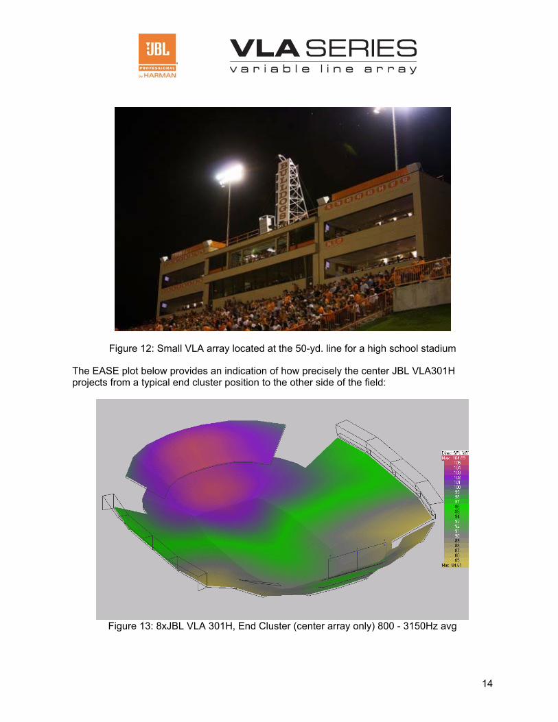
Figure 12: Small VLA array located at the 50-yd. line for a high school stadium
The EASE plot below provides an indication of how precisely the center JBL VLA301H projects from a typical end cluster position to the other side of the field:
Figure 13: 8xJBL VLA 301H, End Cluster (center array only) 800 - 3150Hz avg
15
Performance Stage Very large auditoriums or houses of worship (in excess of 5,000 seats) are excellent candidates for large line array systems. Again, JBL VLA SERIES arrays can improve the results of typical line array system by reducing overlap between arrays and spilling less energy on the side walls.
Especially in very large, acoustically challenging rooms, the narrower and well-behaved coverage of the JBL VLA SERIES can improve the direct-to-reverberant ratio measured in the seats. These improvements will provide greater speech intelligibility and musical clarity.
Outdoor Performance Venue The improved horizontal directivity of the JBL VLA SERIES line arrays can improve the focus of the system on the seating areas while reducing sound levels in surrounding neighborhoods.
Using a JBL VLA601H or JBL VLA301H array instead of a conventional large format line array for mains can reduce the levels 90 degrees left and right of the stage by 4 to 6 dB between 500 and 2000Hz.
For the very extreme throws for some of these types of events, a conventional large-format tour line array system simply may not be able to project to the distances required. The delay towers typically used to solve this problem may not be necessary in some cases if a JBL VLA SERIES array is used for the extreme throws.
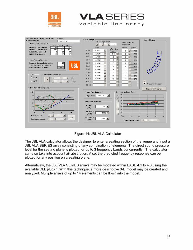
Computer Modeling Modeling the JBL VLA SERIES arrays can be done in two ways. The JBL VLA Calculator is available to provide simple, 2-D modeling of the arrays response on the seating planes. An example screen is shown below:
16
Figure 14: JBL VLA Calculator
The JBL VLA calculator allows the designer to enter a seating section of the venue and input a JBL VLA SERIES array consisting of any combination of elements. The direct sound pressure level for the seating plane is plotted for up to 3 frequency bands concurrently. The calculator can also take into account air absorption. Also, the predicted frequency response can be plotted for any position on a seating plane.
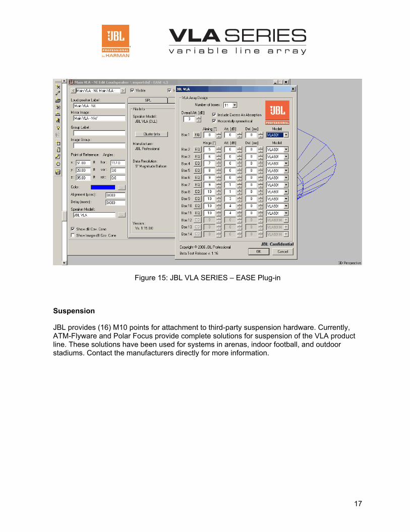
Alternatively, the JBL VLA SERIES arrays may be modeled within EASE 4.1 to 4.3 using the available DLL plug-in. With this technique, a more descriptive 3-D model may be created and analyzed. Multiple arrays of up to 14 elements can be flown into the model.
17
Figure 15: JBL VLA SERIES – EASE Plug-in
Suspension
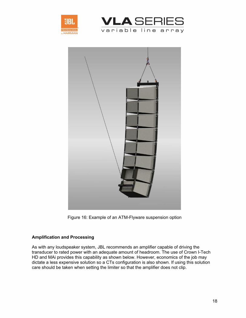
JBL provides (16) M10 points for attachment to third-party suspension hardware. Currently, ATM-Flyware and Polar Focus provide complete solutions for suspension of the VLA product line. These solutions have been used for systems in arenas, indoor football, and outdoor stadiums. Contact the manufacturers directly for more information.
18
Figure 16: Example of an ATM-Flyware suspension option
Amplification and Processing
As with any loudspeaker system, JBL recommends an amplifier capable of driving the transducer to rated power with an adequate amount of headroom. The use of Crown I-Tech HD and MAi provides this capability as shown below. However, economics of the job may dictate a less expensive solution so a CTs configuration is also shown. If using this solution care should be taken when setting the limiter so that the amplifier does not clip.
19
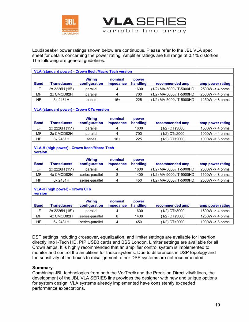
Loudspeaker power ratings shown below are continuous. Please refer to the JBL VLA spec sheet for details concerning the power rating. Amplifier ratings are full range at 0.1% distortion. The following are general guidelines.
VLA (standard power) - Crown Itech/Macro Tech version
Band Transducers Wiring
configuration nominal
impedance power
handling recommended amp amp power rating LF 2x 2226H (15") parallel 4 1600 (1/2) MA-5000i/IT-5000HD 2500W -> 4 ohms MF 2x CMCD82H parallel 4 700 (1/2) MA-5000i/IT-5000HD 2500W -> 4 ohms HF 3x 2431H series 16+ 225 (1/2) MA-5000i/IT-5000HD 1250W -> 8 ohms
VLA (standard power) - Crown CTs version
Band Transducers Wiring
configuration nominal
impedance power
handling recommended amp amp power rating LF 2x 2226H (15") parallel 4 1600 (1/2) CTs3000 1500W -> 4 ohms MF 2x CMCD82H parallel 4 700 (1/2) CTs2000 1000W -> 4 ohms HF 3x 2431H series 16+ 225 (1/2) CTs2000 1000W -> 8 ohms
VLA-H (high power) - Crown Itech/Macro Tech version
Band Transducers Wiring
configuration nominal
impedance power
handling recommended amp amp power rating LF 2x 2226H (15") parallel 4 1600 (1/2) MA-5000i/IT-5000HD 2500W -> 4 ohms MF 4x CMCD82H series-parallel 8 1400 (1/2) MA-9000i/IT-9000HD 1500W -> 8 ohms HF 6x 2431H series-parallel 4 450 (1/2) MA-5000i/IT-5000HD 2500W -> 4 ohms
VLA-H (high power) - Crown CTs version
Band Transducers Wiring
configuration nominal
impedance power
handling recommended amp amp power rating LF 2x 2226H (15") parallel 4 1600 (1/2) CTs3000 1500W -> 4 ohms MF 4x CMCD82H series-parallel 8 1400 (1/2) CTs3000 1250W -> 4 ohms HF 6x 2431H series-parallel 4 450 (1/2) CTs2000 1000W -> 8 ohms
DSP settings including crossover, equalization, and limiter settings are available for insertion directly into I-Tech HD, PIP USB3 cards and BSS London. Limiter settings are available for all Crown amps. It is highly recommended that an amplifier control system is implemented to monitor and control the amplifiers for these systems. Due to differences in DSP topology and the sensitivity of the boxes to misalignment, other DSP systems are not recommended.
Summary Combining JBL technologies from both the VerTec® and the Precision Directivity® lines, the development of the JBL VLA SERIES line provides the designer with new and unique options for system design. VLA systems already implemented have consistently exceeded performance expectations.
1
JBL Professional 8500 Balboa Boulevard, P.O. Box 2200 Northridge, CA 91329
A Harman International Company © Copyright 2010 JBL Professional
Part #: VLA WP v.2 JBL VLA SERIES White Paper 01/10


![[JBL S3900] JBL 가문에서 출중한 미인이 탄생하다 - 월간오디오](https://img.dokumen.tips/doc/110x75/568c36b21a28ab0235990729/jbl-s3900-jbl-.jpg)