Embed Size (px)
Citation preview

JBL GTR AMPLIFIERSGTR‐7535/GTR‐104/GTR‐102/ GTR-1001/GTR-601
POWER AMPLIFIERS
OWNER’S MANUAL
ENGLISH
GTR AMPLIFIERSTHANK YOU FOR YOUR PURCHASE . . .
Your JBL product has been designed to provide you with the performance and ease of operation you would expect from JBL.
• Please take time to read your owner’s manual in its entirety before operating or installing your amplifier.
• Keep the owner’s manual for your amplifier in your glove compartment along with the owner’s manual for your car.
• Put your amplifier sales receipt with other important documents in order to expedite warranty service if needed.
GTR mono and full-range multi-channel amplifiers deliver the efficiency and power you expect from Class D amps. The subwoofer amplifiers feature high efficiency design, a low-noise and low-distortion signal path, and low-level and high-level inputs. The 2-, 4- and 5-channel amplifiers offer Bluetooth audio streaming. GTR amps also feature Party Mode™, a multi-pairing Bluetooth feature which lets up to three of the vehicle’s occupants stream their music over the audio system. Clari-Fi™—a proprietary audio restoration technology—improves the overall audio quality of compressed files and restores natural warmth and ambience to the music. You will discover numerous other features and refinements that will shape the car audio experience to suit your personal preference.
ABOUT THE MANUAL
This manual describes general installation guidelines and operation instructions. However, please note that proper installation of mobile audio and video components requires qualified experience with mechanical and electrical procedures. If you do not have the knowledge and tools to successfully perform this installation, we strongly recommend consulting an authorized JBL dealer about your installation options. Keep all instructions and sales receipts for reference. Consider this manual as an indispensable feature of your amplifier.
GTR AMPLIFIERSTABLE OF CONTENTS
CHAPTER 1: PICTORIAL INDEX OF INPUT CONNECTIONS ................................................................................................................................ 1
CHAPTER 2: INSTALLATION AND WIRING ................................................................................................................................ 2
What’s in the box ................................................................................................................................ 2Precautions ................................................................................................................................ 21. Speaker output connectors ................................................................................................................................ 32. Fuses ................................................................................................................................ 43. Power input connector’s ................................................................................................................................ 44. Remote (GTR-102, GTR-104, GTR-7535) ................................................................................................................................ 55. Front and rear inputs and outputs (RCA) ................................................................................................................................ 56. Input level ................................................................................................................................ 57. Crossover filter selectors ................................................................................................................................ 58. Gain ................................................................................................................................ 59. Crossover Frequency controls ................................................................................................................................ 510. ADAS Assign (GTR-102, GTR-104, GTR-7535) ................................................................................................................................ 511. Controller (GTR-102, GTR-104, GTR-7535) ................................................................................................................................ 512. REM (GTR-102, GTR-104) ................................................................................................................................ 613. ADAS Input (GTR-102, GTR-104, GTR-7535) ................................................................................................................................ 614. Input for firmware updates ................................................................................................................................ 615. Power/Protect Indicator ................................................................................................................................ 616. Clari-Fi indicator (GTR-102, GTR-104, GTR-7535) ................................................................................................................................ 617. Party mode indicator (GTR-102, GTR-104, GTR-7535) ................................................................................................................................ 618. Bluetooth indicator (GTR-102, GTR-104, GTR-75352) ................................................................................................................................ 6
CHAPTER 3: REMOTE CONTROLLER (Controls and Indicators) ................................................................................................................................ 719. Phone Call button ................................................................................................................................ 720. Phone End button ................................................................................................................................ 721. Power/Protect Indicator ................................................................................................................................ 722. Clari-Fi indicator ................................................................................................................................ 7 23. Operating mode indicator ................................................................................................................................ 724. Bluetooth indicator ................................................................................................................................ 725. Operating mode button ................................................................................................................................ 726. Power button ................................................................................................................................ 727. Bluetooth pairing button ................................................................................................................................ 728. Clari-Fi button ................................................................................................................................ 8
CHAPTER 4: Operations ................................................................................................................................ 8Bluetooth Functions ................................................................................................................................ 8Party Mode ................................................................................................................................ 8Audio Input Priorities ................................................................................................................................ 8Clari-Fi Audio Restoration Technology ................................................................................................................................ 8Setting the Input Level Controls ................................................................................................................................ 8Setting the Crossover ................................................................................................................................ 9Adjusting the subwoofer ................................................................................................................................ 9Selecting subwoofer phase ................................................................................................................................ 9Bass Boost EQ ................................................................................................................................ 9
CHAPTER 5: TROUBLESHOOTING .............................................................................................................................. 10CHAPTER 6: SPECIFICATIONS .............................................................................................................................. 10
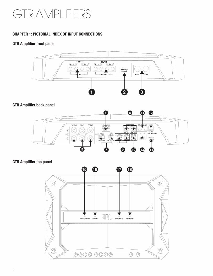
GTR AMPLIFIERSCHAPTER 1: PICTORIAL INDEX OF INPUT CONNECTIONS
GTR Amplifier front panel
GTR Amplifier back panel
GTR Amplifier top panel
Power/Protect Clari-Fi Party Mode Bluetooth®TM
15 16 17 18
—+ L —+ R —+ L —+ RFRONT
BRIDGED
REAR
+ BRIDGED +
FUSES30A x2
+12V GND
1 2 3
FRONT INPUT LEVEL LO
FRONTX-OVER
REARX-OVER
HI1 HI2
REARPRE OUT
R
L
LPF FULL HPF LPF FULL HPF
GAIN
FREQ ADAS ASSIGN
MIN• • • •
MINMAX MAX
REAR FRONT
CONTROLLER REM
ADAS
UPGRADE
INPUTREAR
80Hz 80Hz
•
•
• •
•
•32Hz 32Hz320Hz 320Hz
FRONT FL FR
RL RR
IN OUT
•
• •
•
6
10 13 147 9
12118
5
1
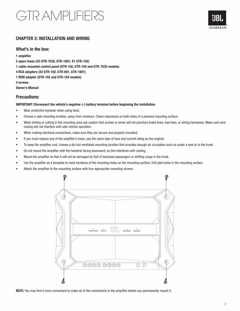
GTR AMPLIFIERSCHAPTER 2: INSTALLATION AND WIRING
What’s in the box:1 amplifier
2 spare fuses (X3 GTR-7535, GTR-1001; X1 GTR-102)
1 cabin-mounted control panel (GTR-102, GTR-104 and GTR-7535 models)
4 RCA adapters (X2 GTR-102, GTR-601, GTR-1001)
1 REM adapter (GTR-102 and GTR-104 models)
4 screws
Owner’s Manual
Precautions:
IMPORTANT: Disconnect the vehicle’s negative (–) battery terminal before beginning the installation.
• Wear protective eyewear when using tools.
• Choose a safe mounting location, away from moisture. Check clearances on both sides of a planned mounting surface.
• When drilling or cutting in the mounting area use caution that screws or wires will not puncture brake lines, fuel lines, or wiring harnesses. Make sure wire routing will not interfere with safe vehicle operation.
• When making electrical connections, make sure they are secure and properly insulated.
• If you must replace any of the amplifier’s fuses, use the same type of fuse and current rating as the original.
• To keep the amplifier cool, choose a dry but ventilated mounting location that provides enough air circulation such as under a seat or in the trunk.
• Do not mount the amplifier with the heatsink facing downward, as this interferes with cooling.
• Mount the amplifier so that it will not be damaged by feet of backseat passengers or shifting cargo in the trunk.
• Use the amplifier as a template to mark locations of the mounting holes on the mounting surface. Drill pilot holes in the mounting surface.
• Attach the amplifier to the mounting surface with four appropriate mounting screws.
NOTE: You may find it more convenient to make all of the connections to the amplifier before you permanently mount it.
Power/Protect Clari-Fi Party Mode Bluetooth®TM
2
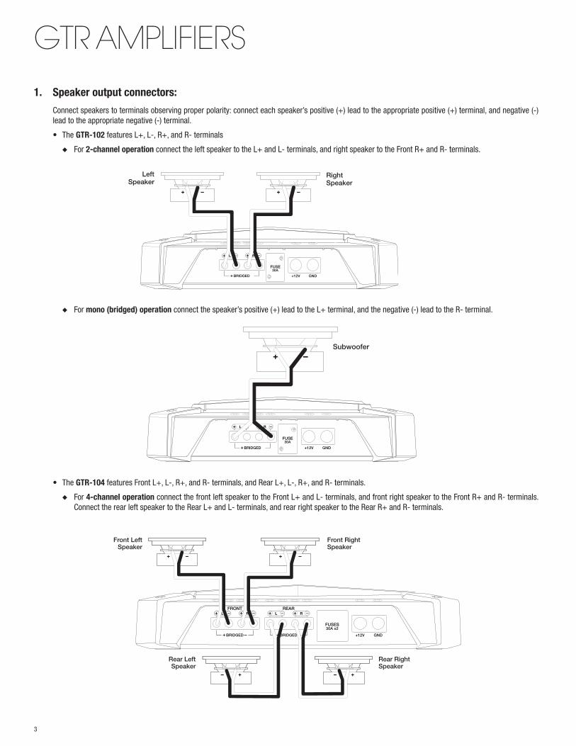
GTR AMPLIFIERS1. Speaker output connectors:
Connect speakers to terminals observing proper polarity: connect each speaker’s positive (+) lead to the appropriate positive (+) terminal, and negative (-) lead to the appropriate negative (-) terminal.
• The GTR-102 features L+, L-, R+, and R- terminals
◆ For 2-channel operation connect the left speaker to the L+ and L- terminals, and right speaker to the Front R+ and R- terminals.
◆ For mono (bridged) operation connect the speaker’s positive (+) lead to the L+ terminal, and the negative (-) lead to the R- terminal.
• The GTR-104 features Front L+, L-, R+, and R- terminals, and Rear L+, L-, R+, and R- terminals.
◆ For 4-channel operation connect the front left speaker to the Front L+ and L- terminals, and front right speaker to the Front R+ and R- terminals. Connect the rear left speaker to the Rear L+ and L- terminals, and rear right speaker to the Rear R+ and R- terminals.
—+ L —+ R
BRIDGED +
FUSE30A
+12V GND
LeftSpeaker
RightSpeaker
—+ L —+ R
BRIDGED +
FUSE30A
+12V GND
Subwoofer
—+ L —+ R —+ L —+ RFRONT
BRIDGED
REAR
+ BRIDGED +
FUSES30A x2
+12V GND
Front LeftSpeaker
Rear LeftSpeaker
Rear RightSpeaker
Front RightSpeaker
3
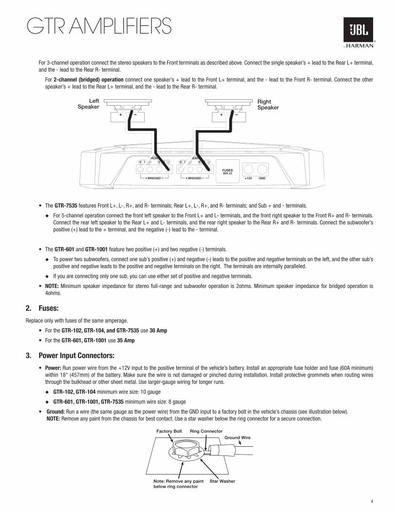
GTR AMPLIFIERS For 3-channel operation connect the stereo speakers to the Front terminals as described above. Connect the single speaker’s + lead to the Rear L+ terminal,
and the - lead to the Rear R- terminal.
For 2-channel (bridged) operation connect one speaker’s + lead to the Front L+ terminal, and the - lead to the Front R- terminal. Connect the other speaker’s + lead to the Rear L+ terminal, and the - lead to the Rear R- terminal.
• The GTR-7535 features Front L+, L-, R+, and R- terminals; Rear L+, L-, R+, and R- terminals; and Sub + and - terminals.
◆ For 5-channel operation connect the front left speaker to the Front L+ and L- terminals, and the front right speaker to the Front R+ and R- terminals. Connect the rear left speaker to the Rear L+ and L- terminals, and the rear right speaker to the Rear R+ and R- terminals. Connect the subwoofer’s positive (+) lead to the + terminal, and the negative (-) lead to the - terminal.
• The GTR-601 and GTR-1001 feature two positive (+) and two negative (-) terminals.
◆ To power two subwoofers, connect one sub’s positive (+) and negative (-) leads to the positive and negative terminals on the left, and the other sub’s positive and negative leads to the positive and negative terminals on the right. The terminals are internally paralleled.
◆ If you are connecting only one sub, you can use either set of positive and negative terminals.
• NOTE: Minimum speaker impedance for stereo full-range and subwoofer operation is 2ohms. Minimum speaker impedance for bridged operation is 4ohms.
2. Fuses:
Replace only with fuses of the same amperage.
• For the GTR-102, GTR-104, and GTR-7535 use 30 Amp
• For the GTR-601, GTR-1001 use 35 Amp
3. Power Input Connectors:
• Power: Run power wire from the +12V input to the positive terminal of the vehicle’s battery. Install an appropriate fuse holder and fuse (60A minimum) within 18" (457mm) of the battery. Make sure the wire is not damaged or pinched during installation. Install protective grommets when routing wires through the bulkhead or other sheet metal. Use larger-gauge wiring for longer runs.
◆ GTR-102, GTR-104 minimum wire size: 10 gauge
◆ GTR-601, GTR-1001, GTR-7535 minimum wire size: 8 gauge
• Ground: Run a wire (the same gauge as the power wire) from the GND input to a factory bolt in the vehicle’s chassis (see illustration below). NOTE: Remove any paint from the chassis for best contact. Use a star washer below the ring connector for a secure connection.
—+ L —+ R —+ L —+ RFRONT
BRIDGED
REAR
+ BRIDGED +
FUSES30A x2
+12V GND
LeftSpeaker
RightSpeaker
Ring Connector
Ground Wire
Star Washer
Factory Bolt
Note: Remove any paint below ring connector
4
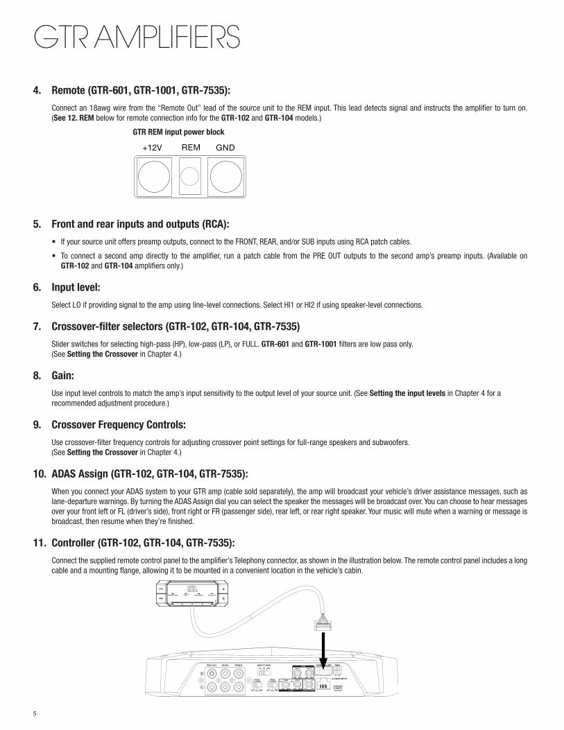
GTR AMPLIFIERS4. Remote (GTR-601, GTR-1001, GTR-7535):
Connect an 18awg wire from the “Remote Out” lead of the source unit to the REM input. This lead detects signal and instructs the amplifier to turn on. (See 12. REM below for remote connection info for the GTR-102 and GTR-104 models.)
GTR REM input power block
5. Front and rear inputs and outputs (RCA):
• If your source unit offers preamp outputs, connect to the FRONT, REAR, and/or SUB inputs using RCA patch cables.
• To connect a second amp directly to the amplifier, run a patch cable from the PRE OUT outputs to the second amp’s preamp inputs. (Available on GTR-102 and GTR-104 amplifiers only.)
6. Input level:
Select LO if providing signal to the amp using line-level connections. Select HI1 or HI2 if using speaker-level connections.
7. Crossover-filter selectors (GTR-102, GTR-104, GTR-7535)
Slider switches for selecting high-pass (HP), low-pass (LP), or FULL. GTR-601 and GTR-1001 filters are low pass only. (See Setting the Crossover in Chapter 4.)
8. Gain:
Use input level controls to match the amp’s input sensitivity to the output level of your source unit. (See Setting the input levels in Chapter 4 for a recommended adjustment procedure.)
9. Crossover Frequency Controls:
Use crossover-filter frequency controls for adjusting crossover point settings for full-range speakers and subwoofers. (See Setting the Crossover in Chapter 4.)
10. ADAS Assign (GTR-102, GTR-104, GTR-7535):
When you connect your ADAS system to your GTR amp (cable sold separately), the amp will broadcast your vehicle’s driver assistance messages, such as lane-departure warnings. By turning the ADAS Assign dial you can select the speaker the messages will be broadcast over. You can choose to hear messages over your front left or FL (driver’s side), front right or FR (passenger side), rear left, or rear right speaker. Your music will mute when a warning or message is broadcast, then resume when they’re finished.
11. Controller (GTR-102, GTR-104, GTR-7535):
Connect the supplied remote control panel to the amplifier’s Telephony connector, as shown in the illustration below. The remote control panel includes a long cable and a mounting flange, allowing it to be mounted in a convenient location in the vehicle’s cabin.
+12V REM GND
FRONT INPUT LEVEL LO
FRONTX-OVER
REARX-OVER
HI1 HI2
REARPRE OUT
R
L
LPF FULL HPF LPF FULL HPF
GAIN
FREQ ADAS ASSIGN
MIN• • • •
MINMAX MAX
REAR FRONT
CONTROLLER REM
ADAS
UPGRADE
INPUTREAR
80Hz 80Hz
•
•
• •
•
•32Hz 32Hz320Hz 320Hz
FRONT FL FR
RL RR
IN OUT
•
• •
•
5
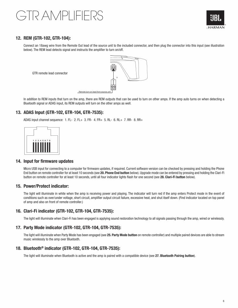
GTR AMPLIFIERS12. REM (GTR-102, GTR-104):
Connect an 18awg wire from the Remote Out lead of the source unit to the included connector, and then plug the connector into this input (see illustration below). The REM lead detects signal and instructs the amplifier to turn on/off.
GTR remote lead connector
In addition to REM inputs that turn on the amp, there are REM outputs that can be used to turn on other amps. If the amp auto turns on when detecting a Bluetooth signal or ADAS input, its REM outputs will turn on the other amps as well.
13. ADAS Input (GTR-102, GTR-104, GTR-7535):
ADAS input channel sequence: 1. FL- 2. FL+ 3. FR- 4. FR+ 5. RL- 6. RL+ 7. RR- 8. RR+
14. Input for firmware updates
Micro USB input for connecting to a computer for firmware updates, if required. Current software version can be checked by pressing and holding the Phone End button on remote controller for at least 10 seconds (see 20. Phone End button below). Upgrade mode can be entered by pressing and holding the Clari-Fi button on remote controller for at least 10 seconds, until all four indicator lights flash for one second (see 28. Clari-Fi button below).
15. Power/Protect indicator:
The light will illuminate in white when the amp is receiving power and playing. The indicator will turn red if the amp enters Protect mode in the event of conditions such as over/under voltage, short circuit, amplifier output circuit failure, excessive heat, and shut itself down. (Find indicator located on top panel of amp and also on front of remote controller.)
16. Clari-Fi indicator (GTR-102, GTR-104, GTR-7535):
The light will illuminate when Clari-Fi has been engaged is applying sound restoration technology to all signals passing through the amp, wired or wirelessly.
17. Party Mode indicator (GTR-102, GTR-104, GTR-7535):
The light will illuminate when Party Mode has been engaged (see 25. Party Mode button on remote controller) and multiple paired devices are able to stream music wirelessly to the amp over Bluetooth.
18. Bluetooth® indicator (GTR-102, GTR-104, GTR-7535):
The light will illuminate when Bluetooth is active and the amp is paired with a compatible device (see 27. Bluetooth Pairing button).
Remote turn-on lead from source unit
1 2 3 4 5 6 7 8
6
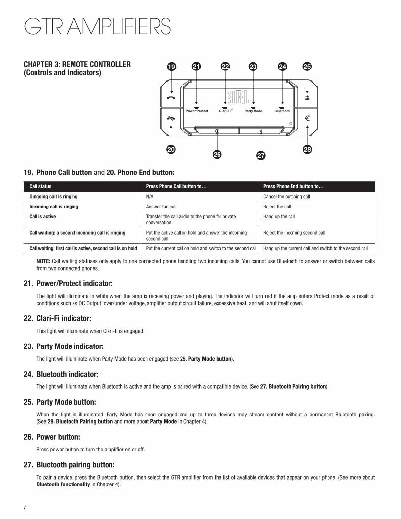
GTR AMPLIFIERSCHAPTER 3: REMOTE CONTROLLER (Controls and Indicators)
19. Phone Call button and 20. Phone End button:
Call status Press Phone Call button to… Press Phone End button to…
Outgoing call is ringing N/A Cancel the outgoing call
Incoming call is ringing Answer the call Reject the call
Call is active Transfer the call audio to the phone for private conversation
Hang up the call
Call waiting: a second incoming call is ringing Put the active call on hold and answer the incoming second call
Reject the incoming second call
Call waiting: first call is active, second call is on hold Put the current call on hold and switch to the second call Hang up the current call and switch to the second call
NOTE: Call waiting statuses only apply to one connected phone handling two incoming calls. You cannot use Bluetooth to answer or switch between calls from two connected phones.
21. Power/Protect indicator:
The light will illuminate in white when the amp is receiving power and playing. The indicator will turn red if the amp enters Protect mode as a result of conditions such as DC Output, over/under voltage, amplifier output circuit failure, excessive heat, and will shut itself down.
22. Clari-Fi indicator:
This light will illuminate when Clari-fi is engaged.
23. Party Mode indicator:
The light will illuminate when Party Mode has been engaged (see 25. Party Mode button).
24. Bluetooth indicator:
The light will illuminate when Bluetooth is active and the amp is paired with a compatible device. (See 27. Bluetooth Pairing button).
25. Party Mode button:
When the light is illuminated, Party Mode has been engaged and up to three devices may stream content without a permanent Bluetooth pairing. (See 29. Bluetooth Pairing button and more about Party Mode in Chapter 4).
26. Power button:
Press power button to turn the amplifier on or off.
27. Bluetooth pairing button:
To pair a device, press the Bluetooth button, then select the GTR amplifier from the list of available devices that appear on your phone. (See more about Bluetooth functionality in Chapter 4).
19 21 22 23 24 25
20 2826 27
7
GTR AMPLIFIERS28. Clari-Fi button:
Press this button to engage Clari-Fi, which automatically applies the appropriate amount of Sound Restoration technology required by the signal coming into the amp, whether through high-level inputs, low-level inputs, or wirelessly. Leave Clari-Fi engaged since it automatically detects and restores compressed music files and will have no effect on uncompressed sources.
CHAPTER 4: OPERATIONS
Bluetooth functionality • Once pairing is complete with a compatible cellular phone, you will be able to make and receive phone calls hands free. You will hear your caller’s voice
over the car speakers and a mic built into the cabin controller will pick up your voice. Any music playing will mute when a call comes in and will stay muted for the duration of the call. Built-in echo cancellation improves call quality by preventing feedback from your car’s speakers.
• You will be able to stream music from a paired device directly to your GTR amp. The amp will play audio files that are stored on your device or from apps on your paired cellular phone.
• Your GTR amp can remember up to 8 paired devices and will automatically recognize and pair with remembered devices. You can pair up to 3 devices simultaneously in Party Mode and 2 devices in multi-point mode. (See below operating mode.)
Supported Bluetooth Protocols
Protocol Function
A2DP 1.3 Music streaming from compatible devices
AVRCP 1.5 Synching volume of device and amp; automatic pausing of music when superseded by audio from a second device
HFP 1.6 Hands-free calling
Operating Mode
• Your GTR amp features two Bluetooth connection modes: Normal and Party Mode.
• Normal Mode lets you connect two devices at once for hands-free calling and audio streaming. Audio will stream from the device most recently selected. NOTE: When making or receiving calls, your GTR amp can handle only one phone call at a time.
• Party Mode lets you connect three devices simultaneously and play music from each—one device at a time. Audio will stream from the device most recently selected, while audio from other AVRCP-compatible devices will pause. You cannot engage in hands-free calling in Party Mode.
• To engage Party Mode, press the Party Mode button on remote controller and an indicator light will illuminate on the remote controller when Party Mode is active. Press the button again to disengage Party Mode and enter Normal Mode.
Audio input priorities For safety and ease of operation reasons, your GTR amp prioritizes audio inputs as follows: 1) ADAS, 2) Bluetooth calls, 3) music/analog audio.
1) ADAS messages will broadcast over phone calls and analog audio signals.
2) Bluetooth phone calls will play over analog audio signals.
3) Analog audio will play when neither ADAS nor Bluetooth call signals are present.
Clari-Fi Audio Restoration Technology • Clari-Fi Audio Restoration technology improves the sound of compressed music such as satellite radio or MP3 files. By analyzing the input signal,
Clari-Fi restores information that’s been lost in the compression process, rebuilding lost details and extending high-frequency bandwidth.
• Clari-Fi applies different degrees of processing as necessary. More compressed files will receive more restoration while less compressed music will receive less.
To engage, press the Clari-Fi button on remote controller. An indicator light will illuminate on the remote controller when Clari-Fi is active.
8
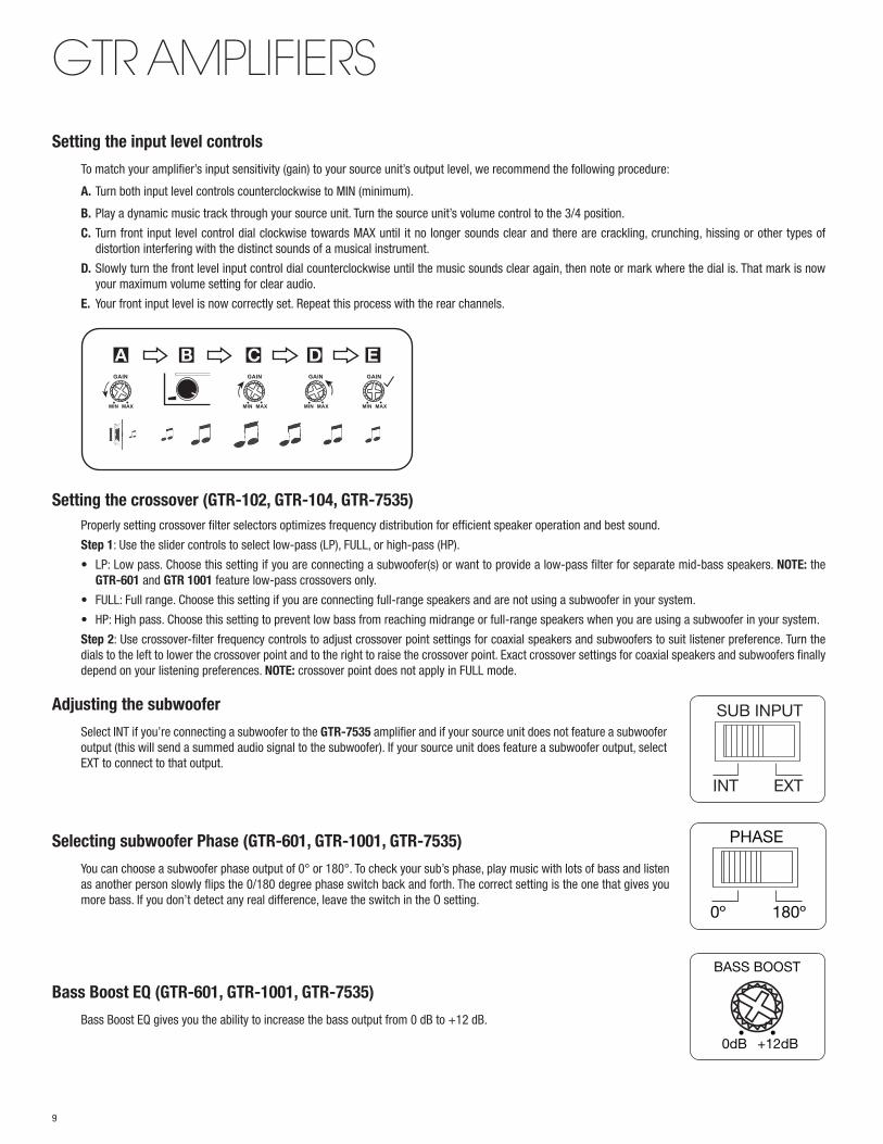
GTR AMPLIFIERSSetting the input level controls
To match your amplifier’s input sensitivity (gain) to your source unit’s output level, we recommend the following procedure:
A. Turn both input level controls counterclockwise to MIN (minimum).
B. Play a dynamic music track through your source unit. Turn the source unit’s volume control to the 3/4 position.
C. Turn front input level control dial clockwise towards MAX until it no longer sounds clear and there are crackling, crunching, hissing or other types of distortion interfering with the distinct sounds of a musical instrument.
D. Slowly turn the front level input control dial counterclockwise until the music sounds clear again, then note or mark where the dial is. That mark is now your maximum volume setting for clear audio.
E. Your front input level is now correctly set. Repeat this process with the rear channels.
Setting the crossover (GTR-102, GTR-104, GTR-7535) Properly setting crossover filter selectors optimizes frequency distribution for efficient speaker operation and best sound.
Step 1: Use the slider controls to select low-pass (LP), FULL, or high-pass (HP).
• LP: Low pass. Choose this setting if you are connecting a subwoofer(s) or want to provide a low-pass filter for separate mid-bass speakers. NOTE: the GTR-601 and GTR 1001 feature low-pass crossovers only.
• FULL: Full range. Choose this setting if you are connecting full-range speakers and are not using a subwoofer in your system.
• HP: High pass. Choose this setting to prevent low bass from reaching midrange or full-range speakers when you are using a subwoofer in your system.
Step 2: Use crossover-filter frequency controls to adjust crossover point settings for coaxial speakers and subwoofers to suit listener preference. Turn the dials to the left to lower the crossover point and to the right to raise the crossover point. Exact crossover settings for coaxial speakers and subwoofers finally depend on your listening preferences. NOTE: crossover point does not apply in FULL mode.
Adjusting the subwoofer
Select INT if you’re connecting a subwoofer to the GTR-7535 amplifier and if your source unit does not feature a subwoofer output (this will send a summed audio signal to the subwoofer). If your source unit does feature a subwoofer output, select EXT to connect to that output.
Selecting subwoofer Phase (GTR-601, GTR-1001, GTR-7535)
You can choose a subwoofer phase output of 0° or 180°. To check your sub’s phase, play music with lots of bass and listen as another person slowly flips the 0/180 degree phase switch back and forth. The correct setting is the one that gives you more bass. If you don’t detect any real difference, leave the switch in the O setting.
Bass Boost EQ (GTR-601, GTR-1001, GTR-7535)
Bass Boost EQ gives you the ability to increase the bass output from 0 dB to +12 dB.
BASS BOOST
0dB +12dB• •
A B C D E
PHASE
0º 180º
SUB INPUT
INT EXT
9
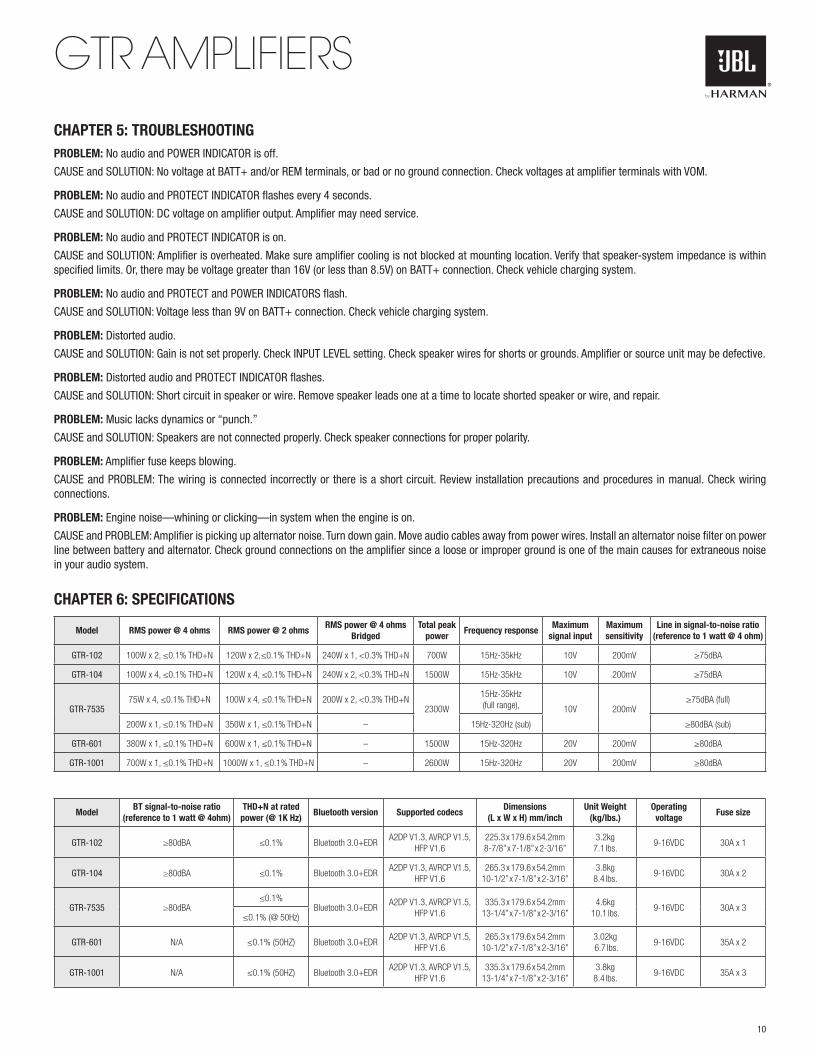
GTR AMPLIFIERSCHAPTER 5: TROUBLESHOOTINGPROBLEM: No audio and POWER INDICATOR is off.
CAUSE and SOLUTION: No voltage at BATT+ and/or REM terminals, or bad or no ground connection. Check voltages at amplifier terminals with VOM.
PROBLEM: No audio and PROTECT INDICATOR flashes every 4 seconds.
CAUSE and SOLUTION: DC voltage on amplifier output. Amplifier may need service.
PROBLEM: No audio and PROTECT INDICATOR is on.
CAUSE and SOLUTION: Amplifier is overheated. Make sure amplifier cooling is not blocked at mounting location. Verify that speaker-system impedance is within specified limits. Or, there may be voltage greater than 16V (or less than 8.5V) on BATT+ connection. Check vehicle charging system.
PROBLEM: No audio and PROTECT and POWER INDICATORS flash.
CAUSE and SOLUTION: Voltage less than 9V on BATT+ connection. Check vehicle charging system.
PROBLEM: Distorted audio.
CAUSE and SOLUTION: Gain is not set properly. Check INPUT LEVEL setting. Check speaker wires for shorts or grounds. Amplifier or source unit may be defective.
PROBLEM: Distorted audio and PROTECT INDICATOR flashes.
CAUSE and SOLUTION: Short circuit in speaker or wire. Remove speaker leads one at a time to locate shorted speaker or wire, and repair.
PROBLEM: Music lacks dynamics or “punch.”
CAUSE and SOLUTION: Speakers are not connected properly. Check speaker connections for proper polarity.
PROBLEM: Amplifier fuse keeps blowing.
CAUSE and PROBLEM: The wiring is connected incorrectly or there is a short circuit. Review installation precautions and procedures in manual. Check wiring connections.
PROBLEM: Engine noise—whining or clicking—in system when the engine is on.
CAUSE and PROBLEM: Amplifier is picking up alternator noise. Turn down gain. Move audio cables away from power wires. Install an alternator noise filter on power line between battery and alternator. Check ground connections on the amplifier since a loose or improper ground is one of the main causes for extraneous noise in your audio system.
CHAPTER 6: SPECIFICATIONS
Model RMS power @ 4 ohms RMS power @ 2 ohmsRMS power @ 4 ohms
BridgedTotal peak
powerFrequency response
Maximum signal input
Maximum sensitivity
Line in signal-to-noise ratio (reference to 1 watt @ 4 ohm)
GTR-102 100W x 2, ≤0.1% THD+N 120W x 2,≤0.1% THD+N 240W x 1, <0.3% THD+N 700W 15Hz-35kHz 10V 200mV ≥75dBA
GTR-104 100W x 4, ≤0.1% THD+N 120W x 4, ≤0.1% THD+N 240W x 2, <0.3% THD+N 1500W 15Hz-35kHz 10V 200mV ≥75dBA
GTR-753575W x 4, ≤0.1% THD+N 100W x 4, ≤0.1% THD+N 200W x 2, <0.3% THD+N
2300W
15Hz-35kHz (full range), 10V 200mV
≥75dBA (full)
200W x 1, ≤0.1% THD+N 350W x 1, ≤0.1% THD+N – 15Hz-320Hz (sub) ≥80dBA (sub)
GTR-601 380W x 1, ≤0.1% THD+N 600W x 1, ≤0.1% THD+N – 1500W 15Hz-320Hz 20V 200mV ≥80dBA
GTR-1001 700W x 1, ≤0.1% THD+N 1000W x 1, ≤0.1% THD+N – 2600W 15Hz-320Hz 20V 200mV ≥80dBA
ModelBT signal-to-noise ratio
(reference to 1 watt @ 4ohm)THD+N at rated power (@ 1K Hz)
Bluetooth version Supported codecs Dimensions
(L x W x H) mm/inchUnit Weight
(kg/lbs.)Operating
voltage Fuse size
GTR-102 ≥80dBA ≤0.1% Bluetooth 3.0+EDRA2DP V1.3, AVRCP V1.5,
HFP V1.6225.3 x 179.6 x 54.2mm 8-7/8” x 7-1/8” x 2-3/16”
3.2kg 7.1 lbs.
9-16VDC 30A x 1
GTR-104 ≥80dBA ≤0.1% Bluetooth 3.0+EDRA2DP V1.3, AVRCP V1.5,
HFP V1.6265.3 x 179.6 x 54.2mm
10-1/2” x 7-1/8” x 2-3/16” 3.8kg
8.4 lbs. 9-16VDC 30A x 2
GTR-7535 ≥80dBA≤0.1%
Bluetooth 3.0+EDRA2DP V1.3, AVRCP V1.5,
HFP V1.6335.3 x 179.6 x 54.2mm
13-1/4” x 7-1/8” x 2-3/16”4.6kg
10.1 lbs.9-16VDC 30A x 3
≤0.1% (@ 50Hz)
GTR-601 N/A ≤0.1% (50HZ) Bluetooth 3.0+EDRA2DP V1.3, AVRCP V1.5,
HFP V1.6265.3 x 179.6 x 54.2mm
10-1/2” x 7-1/8” x 2-3/16”3.02kg 6.7 lbs.
9-16VDC 35A x 2
GTR-1001 N/A ≤0.1% (50HZ) Bluetooth 3.0+EDRA2DP V1.3, AVRCP V1.5,
HFP V1.6335.3 x 179.6 x 54.2mm
13-1/4” x 7-1/8” x 2-3/16”3.8kg
8.4 lbs. 9-16VDC 35A x 3
10

HARMAN International Industries, Incorporated 8500 Balboa Boulevard, Northridge, CA 91329 USAwww.jbl.com
© 2016 HARMAN International Industries, Incorporated. All rights reserved. JBL is a trademark of HARMAN International Industries, Incorporated, registered in the United States and/or other countries. Features, specifications and appearance are subject to change without notice.
11
GTR AMPLIFIERS