Embed Size (px)
Citation preview
JAUFLEX® ELASTIC COUPLINGS
couplings
2
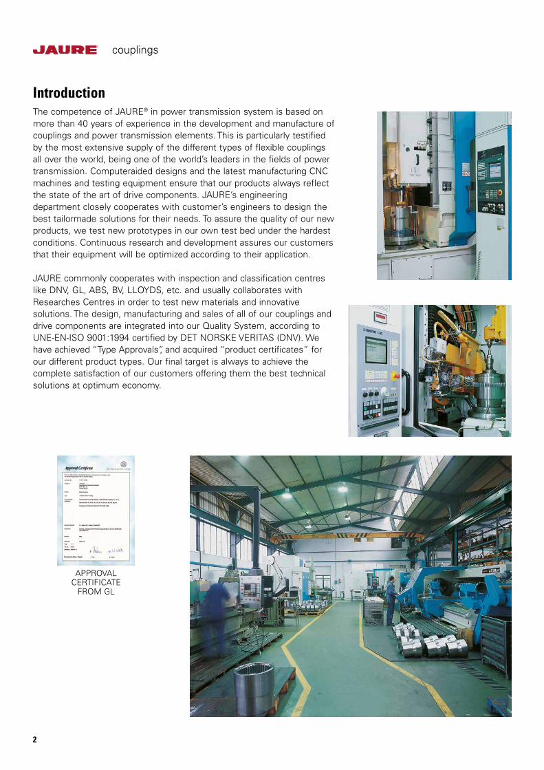
IntroductionThe competence of JAURE® in power transmission system is based on more than 40 years of experience in the development and manufacture of couplings and power transmission elements. This is particularly testified by the most extensive supply of the different types of flexible couplings all over the world, being one of the world’s leaders in the fields of power transmission. Computeraided designs and the latest manufacturing CNC machines and testing equipment ensure that our products always reflect the state of the art of drive components. JAURE’s engineering department closely cooperates with customer’s engineers to design the best tailormade solutions for their needs. To assure the quality of our new products, we test new prototypes in our own test bed under the hardest conditions. Continuous research and development assures our customers that their equipment will be optimized according to their application.
JAURE commonly cooperates with inspection and classification centres like DNV, GL, ABS, BV, LLOYDS, etc. and usually collaborates with Researches Centres in order to test new materials and innovative solutions. The design, manufacturing and sales of all of our couplings and drive components are integrated into our Quality System, according to UNE-EN-ISO 9001:1994 certified by DET NORSKE VERITAS (DNV). We have achieved “Type Approvals”, and acquired “product certificates” for our different product types. Our final target is always to achieve the complete satisfaction of our customers offering them the best technical solutions at optimum economy.
APPROVAL CERTIFICATE
FROM GL
couplings
3
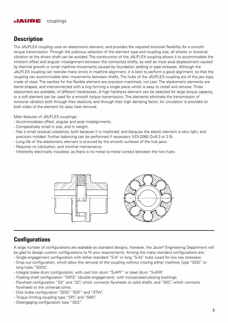
DescriptionThe JAUFLEX coupling uses an elastomeric element, and provides the required torsional flexibility for a smooth torque transmission. Through the judicious selection of the element type and coupling size, all shocks or torsional vibration at the driven shaft can be avoided. The construction of the JAUFLEX coupling allows it to accommodate the inherent offset and angular misalignment between the connected shafts, as well as most axial displacement caused by thermal growth or small machine movements caused by foundation settling or pipe stresses. Although the JAUFLEX coupling can tolerate many errors in machine alignment, it is best to perform a good alignment, so that the coupling can accommodate later movements between shafts. The hubs of the JAUFLEX coupling are of the jaw type, made of steel. The cavities for the flexible element are precision machined, not cast. The elastomeric elements are barrel shaped, and interconnected with a ring forming a single piece which is easy to install and remove. Three elastomers are available, of different hardnesses. A high hardness element can be selected for large torque capacity, or a soft element can be used for a smooth torque transmission. The elements eliminate the transmission of torsional vibration both through their elasticity and through their high damping factor. Air circulation is provided on both sides of the element for easy heat removal.
Main features of JAUFLEX couplings:- Accommodates offset, angular and axial misalignments.- Comparatively small in size, and in weight.- Has a small residual unbalance, both because it is machined, and because the elastic element is very light, and precision molded. Further balancing can be performed if necessary (VDI-2060 Q=6.3 or 2.5)- Long life of the elastomeric element is ensured by the smooth surfaces of the hub jaws.- Requires no lubrication, and minimal maintenance.- Inherently electrically insulated, as there is no metal to-metal contact between the two hubs.
ConfigurationsA large number of configurations are available as standard designs, however, the Jaure® Engineering Department will be glad to design custom configurations to fit your requirements. Among the many standard configurations are:- Single engagement configuration with either standard “S-A” or long “S-AL” hubs (used for low key stresses).- Drop out configuration, which allow the removal of the coupling without moving either machine; type “SDD” or long hubs “SDDL”..- Integral brake drum configuration, with cast iron drum “S-APF” or steel drum “S-APA”.- Floating shaft configuration “SXFS” (double engagement), with incorporated piloting bushings.- Flywheel configuration “SX” and “SZ”, which connects flywheels to solid shafts, and “SXC”, which connects flywheels to the universal joints.- Disk brake configuration “SDD”, “SDF” and “STW”.- Torque limiting coupling type “SPL” and “SBR”.- Disengaging configuration type “SES”.
couplings
4
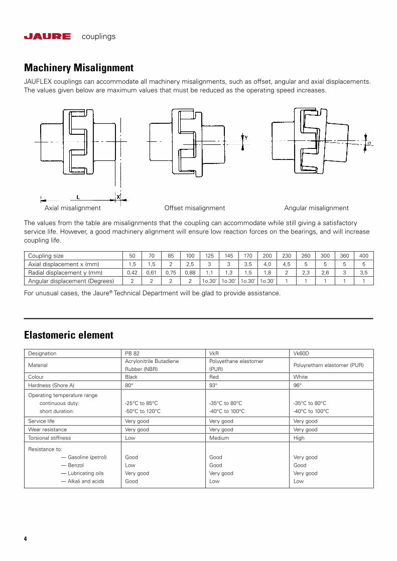
Machinery MisalignmentJAUFLEX couplings can accommodate all machinery misalignments, such as offset, angular and axial displacements. The values given below are maximum values that must be reduced as the operating speed increases.
For unusual cases, the Jaure® Technical Department will be glad to provide assistance.
The values from the table are misalignments that the coupling can accommodate while still giving a satisfactory service life. However, a good machinery alignment will ensure low reaction forces on the bearings, and will increase coupling life.
Axial misalignment Offset misalignment Angular misalignment
Coupling size 50 70 85 100 125 145 170 200 230 260 300 360 400
Axial displacement x (mm) 1,5 1,5 2 2,5 3 3 3,5 4,0 4,5 5 5 5 5
Radial displacement y (mm) 0,42 0,61 0,75 0,88 1,1 1,3 1,5 1,8 2 2,3 2,6 3 3,5
Angular displacement (Degrees) 2 2 2 2 1o.30’ 1o.30’ 1o.30’ 1o.30’ 1 1 1 1 1
Designation PB 82 VkR Vk60D
MaterialAcrylonitrile ButadieneRubber (NBR)
Poluyethane elastomer(PUR)
Poluyretham elastomer (PUR)
Colour Black Red White
Hardness (Shore A) 80° 93° 96°
Operating temperature range continuous duty: short duration:
-25°C to 85°C-50°C to 120°C
-35°C to 80°C-40°C to 100°C
-35°C to 80°C-40°C to 100°C
Service life Very good Very good Very good
Wear resistance Very good Very good Very good
Torsional stiffness Low Medium High
Resistance to: — Gasoline (petrol) — Benzol — Lubricating oils — Alkali and acids
GoodLowVery goodGood
GoodGoodVery goodLow
Very goodGoodVery goodLow
Elastomeric element
couplings
5
ST
AN
DA
RD
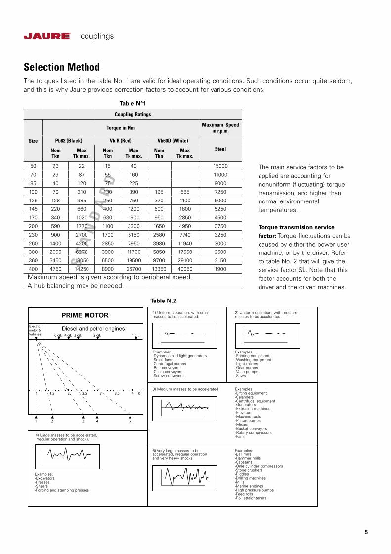
Selection MethodThe torques listed in the table No. 1 are valid for ideal operating conditions. Such conditions occur quite seldom, and this is why Jaure provides correction factors to account for various conditions.
The main service factors to be applied are accounting for nonuniform (fluctuating) torque transmission, and higher than normal environmental temperatures. Torque transmision service factor: Torque fluctuations can be caused by either the power user machine, or by the driver. Refer to table No. 2 that will give the service factor SL. Note that this factor accounts for both the driver and the driven machines.
Table N°1
Coupling Ratings
Size
Torque in Nm Maximum Speedin r.p.m.
Pb82 (Black) Vk R (Red) Vk60D (White)
SteelNomTkn
MaxTk max.
NomTkn
MaxTk max.
NomTkn
MaxTk max.
50 7,3 22 15 40 15000
70 29 87 55 160 11000
85 40 120 75 225 9000
100 70 210 130 390 195 585 7250
125 128 385 250 750 370 1100 6000
145 220 660 400 1200 600 1800 5250
170 340 1020 630 1900 950 2850 4500
200 590 1770 1100 3300 1650 4950 3750
230 900 2700 1700 5150 2580 7740 3250
260 1400 4200 2850 7950 3980 11940 3000
300 2090 6270 3900 11700 5850 17550 2500
360 3450 13050 6500 19500 9700 29100 2150
400 4750 14250 8900 26700 13350 40050 1900
Maximum speed is given according to peripheral speed. A hub balancing may be needed.
Table N.2
4) Large masses to be accelerated, irregular operation and shocks.
Examples:-Lifting equipment-Calanders-Centrifugal equipment-Generators-Extrusion machines-Elevators-Machine tools-Piston pumps-Mixers-Bucket conveyors-Rotary compressors-Fans
Examples:-Ball mills-Hammer mills-Capstans-Onle cylinder compressors-Stone crushers-Riddles-Drilling machines-Mills-Marine engines-High pressure pumps-Feed rolls-Roll straighteners
Examples:-Excavators-Presses-Shears-Forging and stamping presses
Examples:-Dynamos and light generators-Small fans-Centrifugal pumps-Belt conveyors-Chain conveyors-Screw conveyors
Examples:-Printing equipment-Washing equipment-Light mixers-Gear pumps-Vane pumps-Saws
1) Uniform operation, with smallmasses to be accelerated.
2) Uniform operation, with medium masses to be accelerated.
3) Medium masses to be accelerated
5) Very large masses to be accelerated, irregular operation and very heavy shocks
1 2
6 cil. 4 cil. 3 cil. 2 cil. 1 cil.
3 4 5
1.51 2 2.5 3 3.5 4 K
PRIME MOTORElectricmotor &turbines
Diesel and petrol engines
couplings
6
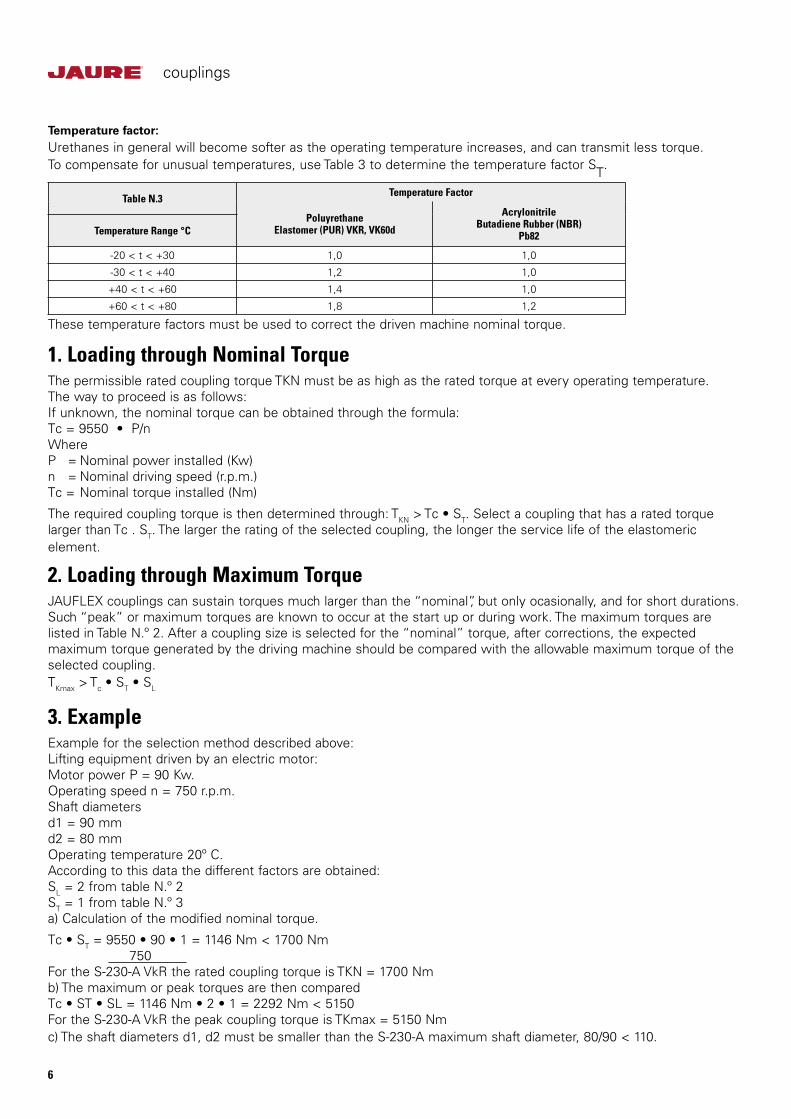
Table N.3 Temperature Factor
PoluyrethaneElastomer (PUR) VKR, VK60d
AcrylonitrileButadiene Rubber (NBR)
Pb82Temperature Range °C
-20 < t < +30 1,0 1,0
-30 < t < +40 1,2 1,0
+40 < t < +60 1,4 1,0
+60 < t < +80 1,8 1,2
Temperature factor:Urethanes in general will become softer as the operating temperature increases, and can transmit less torque. To compensate for unusual temperatures, use Table 3 to determine the temperature factor ST.
These temperature factors must be used to correct the driven machine nominal torque.
1. Loading through Nominal TorqueThe permissible rated coupling torque TKN must be as high as the rated torque at every operating temperature. The way to proceed is as follows:If unknown, the nominal torque can be obtained through the formula: Tc = 9550 • P/nWhereP = Nominal power installed (Kw) n = Nominal driving speed (r.p.m.) Tc = Nominal torque installed (Nm)
The required coupling torque is then determined through: TKN > Tc • ST. Select a coupling that has a rated torque larger than Tc . ST. The larger the rating of the selected coupling, the longer the service life of the elastomeric element.
2. Loading through Maximum TorqueJAUFLEX couplings can sustain torques much larger than the “nominal”, but only ocasionally, and for short durations. Such “peak” or maximum torques are known to occur at the start up or during work. The maximum torques are listed in Table N.º 2. After a coupling size is selected for the “nominal” torque, after corrections, the expected maximum torque generated by the driving machine should be compared with the allowable maximum torque of the selected coupling. TKmax > Tc • ST • SL
3. ExampleExample for the selection method described above:Lifting equipment driven by an electric motor: Motor power P = 90 Kw.Operating speed n = 750 r.p.m.Shaft diameters d1 = 90 mmd2 = 80 mmOperating temperature 20º C.According to this data the different factors are obtained: SL = 2 from table N.º 2ST = 1 from table N.º 3a) Calculation of the modified nominal torque.
Tc • ST = 9550 • 90 • 1 = 1146 Nm < 1700 Nm 750For the S-230-A VkR the rated coupling torque is TKN = 1700 Nmb) The maximum or peak torques are then comparedTc • ST • SL = 1146 Nm • 2 • 1 = 2292 Nm < 5150For the S-230-A VkR the peak coupling torque is TKmax = 5150 Nmc) The shaft diameters d1, d2 must be smaller than the S-230-A maximum shaft diameter, 80/90 < 110.
couplings
7
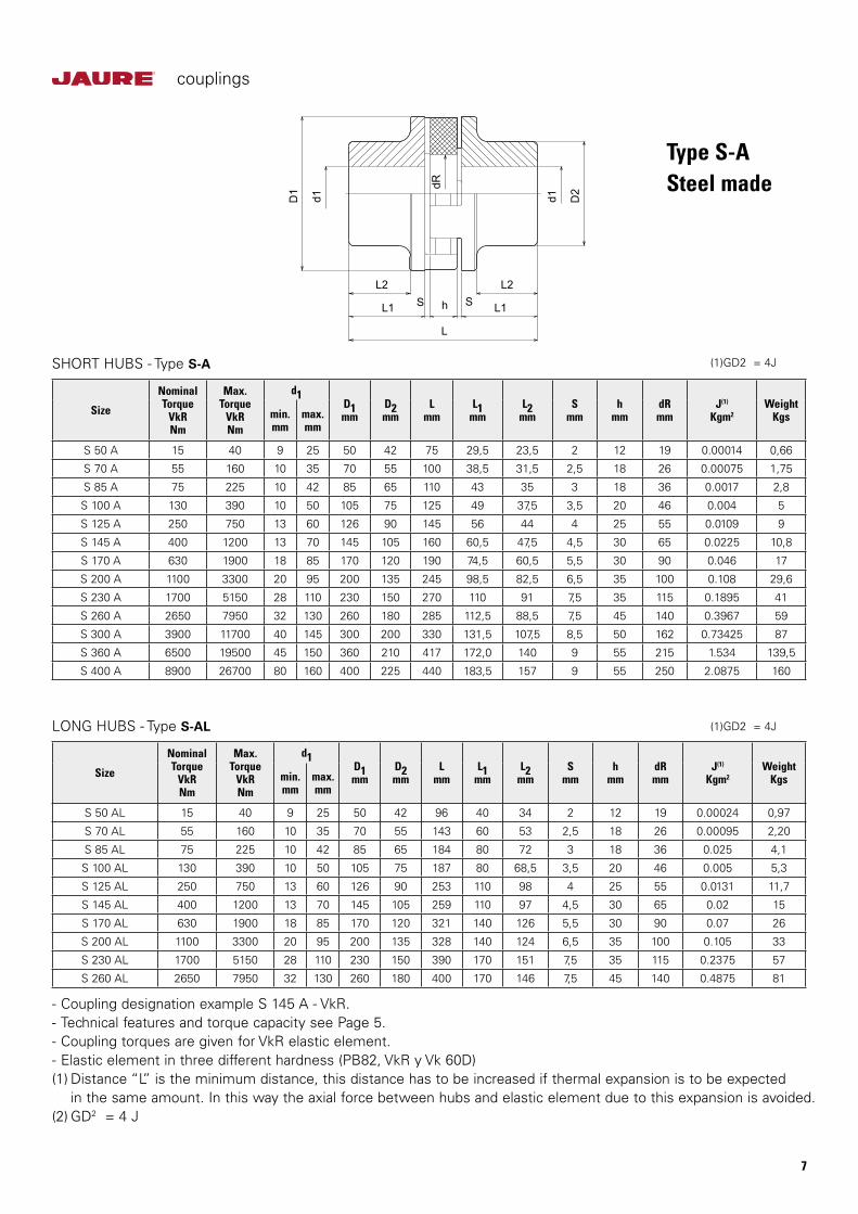
Type S-ASteel made
- Coupling designation example S 145 A - VkR.- Technical features and torque capacity see Page 5.- Coupling torques are given for VkR elastic element.- Elastic element in three different hardness (PB82, VkR y Vk 60D)(1) Distance “L” is the minimum distance, this distance has to be increased if thermal expansion is to be expected in the same amount. In this way the axial force between hubs and elastic element due to this expansion is avoided.(2) GD2 = 4 J
Size
NominalTorque
VkRNm
Max.Torque
VkRNm
d1D1mm
D2mm
Lmm
L1mm
L2mm
Smm
hmm
dRmm
J(1)
Kgm2Weight
Kgsmin.mm
max.mm
S 50 A 15 40 9 25 50 42 75 29,5 23,5 2 12 19 0.00014 0,66
S 70 A 55 160 10 35 70 55 100 38,5 31,5 2,5 18 26 0.00075 1,75
S 85 A 75 225 10 42 85 65 110 43 35 3 18 36 0.0017 2,8
S 100 A 130 390 10 50 105 75 125 49 37,5 3,5 20 46 0.004 5
S 125 A 250 750 13 60 126 90 145 56 44 4 25 55 0.0109 9
S 145 A 400 1200 13 70 145 105 160 60,5 47,5 4,5 30 65 0.0225 10,8
S 170 A 630 1900 18 85 170 120 190 74,5 60,5 5,5 30 90 0.046 17
S 200 A 1100 3300 20 95 200 135 245 98,5 82,5 6,5 35 100 0.108 29,6
S 230 A 1700 5150 28 110 230 150 270 110 91 7,5 35 115 0.1895 41
S 260 A 2650 7950 32 130 260 180 285 112,5 88,5 7,5 45 140 0.3967 59
S 300 A 3900 11700 40 145 300 200 330 131,5 107,5 8,5 50 162 0.73425 87
S 360 A 6500 19500 45 150 360 210 417 172,0 140 9 55 215 1.534 139,5
S 400 A 8900 26700 80 160 400 225 440 183,5 157 9 55 250 2.0875 160
Size
NominalTorque
VkRNm
Max.Torque
VkRNm
d1D1mm
D2mm
Lmm
L1mm
L2mm
Smm
hmm
dRmm
J(1)
Kgm2Weight
Kgsmin.mm
max.mm
S 50 AL 15 40 9 25 50 42 96 40 34 2 12 19 0.00024 0,97
S 70 AL 55 160 10 35 70 55 143 60 53 2,5 18 26 0.00095 2,20
S 85 AL 75 225 10 42 85 65 184 80 72 3 18 36 0.025 4,1
S 100 AL 130 390 10 50 105 75 187 80 68,5 3,5 20 46 0.005 5,3
S 125 AL 250 750 13 60 126 90 253 110 98 4 25 55 0.0131 11,7
S 145 AL 400 1200 13 70 145 105 259 110 97 4,5 30 65 0.02 15
S 170 AL 630 1900 18 85 170 120 321 140 126 5,5 30 90 0.07 26
S 200 AL 1100 3300 20 95 200 135 328 140 124 6,5 35 100 0.105 33
S 230 AL 1700 5150 28 110 230 150 390 170 151 7,5 35 115 0.2375 57
S 260 AL 2650 7950 32 130 260 180 400 170 146 7,5 45 140 0.4875 81
SHORT HUBS - Type S-A
LONG HUBS - Type S-AL
L2 L2
L1 S h S L1
L
dR
d1 D2
d1D1
(1) GD2 = 4J
(1) GD2 = 4J
couplings
8
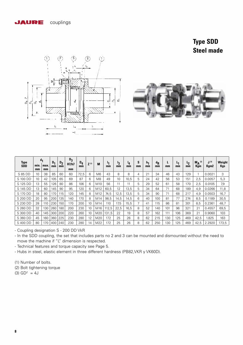
TypeSDD
d1 D1mm
D2mm
D3H7/h7mm
D4mm Z (1) M l1
mml3
mml4
mmS
mmh1
mmdRmm
Lmm
L1mm
L2mm
MA (2)
KgmJ (3)
Kgm2Weight
Kgsmin.mm
max.mm
S 85 DD 10 38 85 60 60 72,5 6 M6 43 8 8 4 21 34 46 43 129 1 0.0021 3S 100 DD 10 42 105 65 69 87 6 M8 49 10 10,5 5 24 42 56 53 151 2,5 0.0057 5,3S 125 DD 13 55 126 80 86 106 6 M10 56 11 11 5 29 52 61 58 170 2,5 0.0105 7,9S 145 DD 13 60 145 90 95 120 6 M12 60,5 12 13,5 5 34 64 71 68 189 4,9 0.0266 11,8S 170 DD 18 80 170 115 120 145 8 M12 74,5 12,5 13,5 5 34 90 71 68 217 4,9 0.0503 16,7S 200 DD 20 95 200 135 140 170 8 M14 98,5 14,5 14,5 6 40 100 81 77 274 8,5 0.1189 30,5S 230 DD 28 110 230 150 170 200 10 M14 110 17,5 15,5 7 41 115 86 81 301 8,5 0.2361 48,7S 260 DD 32 130 260 180 200 230 10 M16 112,5 22,5 16,5 8 52 140 101 96 321 21 0.4557 69,5S 300 DD 40 145 300 200 220 260 10 M20 131,5 22 19 8 57 162 111 106 369 21 0.9060 103S 360 DD 45 160 360 225 230 280 12 M20 172 25 26 8 62 215 130 125 469 42,5 1.825 163S 400 DD 80 170 400 240 230 280 14 M22 172 25 26 8 62 250 130 125 469 42,5 2.2920 173,5
- Coupling designation S - 200 DD VkR- In the SDD coupling, the set that includes parts no 2 and 3 can be mounted and dismounted without the need to move the machine if “L” dimension is respected.- Technical features and torque capacity see Page 5.- Hubs in steel, elastic element in three different hardness (PB82,VKR y VK60D).
(1) Number of bolts.(2) Bolt tightening torque(3) GD2 = 4J
Type SDDSteel made

couplings
9
TypeS-APF oS-APA
Dmm
Bmm
d1max.mm
d2max.mm
R.p.m.D1mm
D2mm
Xmm
l1mm
L (1)
mmJ (3)
Kgm2Weight
KgsMA (2)
Kgm2Grey
cast ironDrum max.
SteelDrummax.
*S 100 APF o APA 200 75 50 42 2.700 4.500 105 75 40 49 125 0.0435 8,4 2,5*S 125 APF o APA 200 75 60 55 2.700 4.500 126 90 40 56 145 0.0503 10,2 2,5*S 145 APF o APA 200 75 70 65 2.700 4.500 145 105 35 60,5 160 0.0597 12,5 4,9*S 145 APF o APA 250 95 70 65 2.300 3.800 145 105 50 60,5 160 0.1396 17,5 4,9*S 170 APF o APA 250 95 85 80 2.300 3.800 170 120 45 74,5 190 0.1658 22,8 4,9*S 170 APF o APA 315 118 85 80 1.800 3.000 170 120 50 74,5 190 0.4181 29,2 4,9*S 200 APF o APA 315 118 95 80 1.800 3.000 200 135 50 98,5 245 0.4593 40 8,5S 200 APF o APA 350 130 95 80 1.600 2.600 200 135 60 98,5 245 0.5822 45 8,5
*S 200 APF o APA 400 150 95 80 1.400 2.300 200 135 75 98,5 245 1.2026 54 8,5*S 230 APF o APA 400 150 110 100 1.400 2.300 230 150 75 110 270 1.2974 68 8,5S 230 APF o APA 450 150 110 100 1.300 2.000 230 150 75 110 270 1.525 75 8,5*S 230 APF o APA 500 190 110 100 1.150 1.900 230 150 100 110 270 3.3899 92 8,5*S 260 APF o APA 500 190 130 120 1.150 1.900 260 180 100 112,5 285 3.5883 110 21*S 260 APF o APA 530 190 130 120 1.050 1.700 260 180 100 112,5 285 3.813 125 21*S 300 APF o APA 630 236 145 130 900 1.500 300 200 120 131,5 330 10.7302 197 21*S 360 APF o APA 630 236 160 140 900 1.500 360 210 114 172 417 11.564 268 42,5
*S 360 APF o APA 710 265 160 140 780 1.200 360 210 123 172 417 20.391 326 42,5
*S 400 APF o APA 710 265 160 150 780 1.200 400 225 132 183,5 440 21.0398 343 42,5
Example of coupling designation S-200-APA/VKR-400* Drum DIN 15431- Technical features and torque capacity see Page 5.- Elastic element in three different hardness (PB82, VKR, VKR60D).
(1) Distance “L” is the minimum distance, this distance has to be increased if thermal expansion is to be expected in the same amount. In this way the axial force between hubs and elastic element due to this expansion is avoided.(2) Bolt tightening torque.(3) GD2 = 4J
a) Type S-APF with grey cast iron drumb) Type S-APA with steel drum
couplings
10
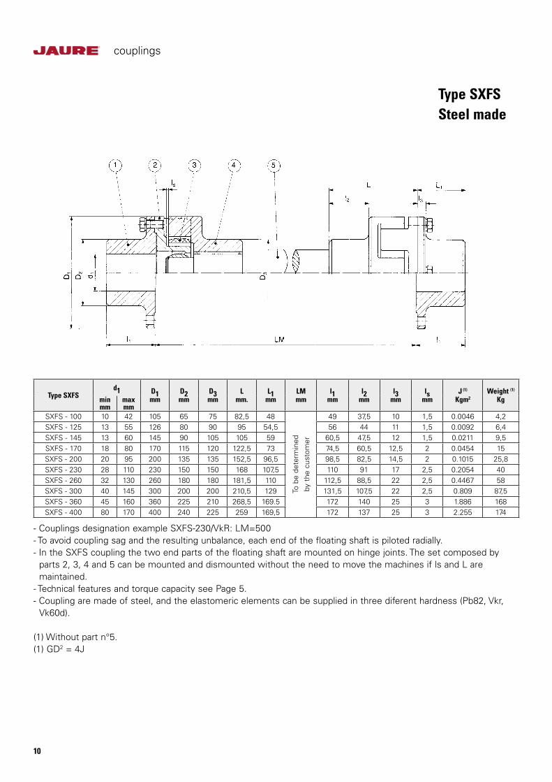
Type SXFSd1 D1
mmD2mm
D3mm
Lmm.
L1mm
LMmm
l1mm
l2mm
l3mm
lsmm
J (1)
Kgm2Weight (1)
Kgminmm
maxmm
SXFS - 100 10 42 105 65 75 82,5 48
To b
e de
term
ined
by t
he c
usto
mer
49 37,5 10 1,5 0.0046 4,2SXFS - 125 13 55 126 80 90 95 54,5 56 44 11 1,5 0.0092 6,4SXFS - 145 13 60 145 90 105 105 59 60,5 47,5 12 1,5 0.0211 9,5SXFS - 170 18 80 170 115 120 122,5 73 74,5 60,5 12,5 2 0.0454 15SXFS - 200 20 95 200 135 135 152,5 96,5 98,5 82,5 14,5 2 0.1015 25,8SXFS - 230 28 110 230 150 150 168 107,5 110 91 17 2,5 0.2054 40SXFS - 260 32 130 260 180 180 181,5 110 112,5 88,5 22 2,5 0.4467 58SXFS - 300 40 145 300 200 200 210,5 129 131,5 107,5 22 2,5 0.809 87,5SXFS - 360 45 160 360 225 210 268,5 169.5 172 140 25 3 1.886 168SXFS - 400 80 170 400 240 225 259 169,5 172 137 25 3 2.255 174
- Couplings designation example SXFS-230/VkR: LM=500- To avoid coupling sag and the resulting unbalance, each end of the floating shaft is piloted radially.- In the SXFS coupling the two end parts of the floating shaft are mounted on hinge joints. The set composed by parts 2, 3, 4 and 5 can be mounted and dismounted without the need to move the machines if ls and L are maintained.- Technical features and torque capacity see Page 5.- Coupling are made of steel, and the elastomeric elements can be supplied in three diferent hardness (Pb82, Vkr, Vk60d).
(1) Without part n°5.(1) GD2 = 4J
Type SXFSSteel made
couplings
11
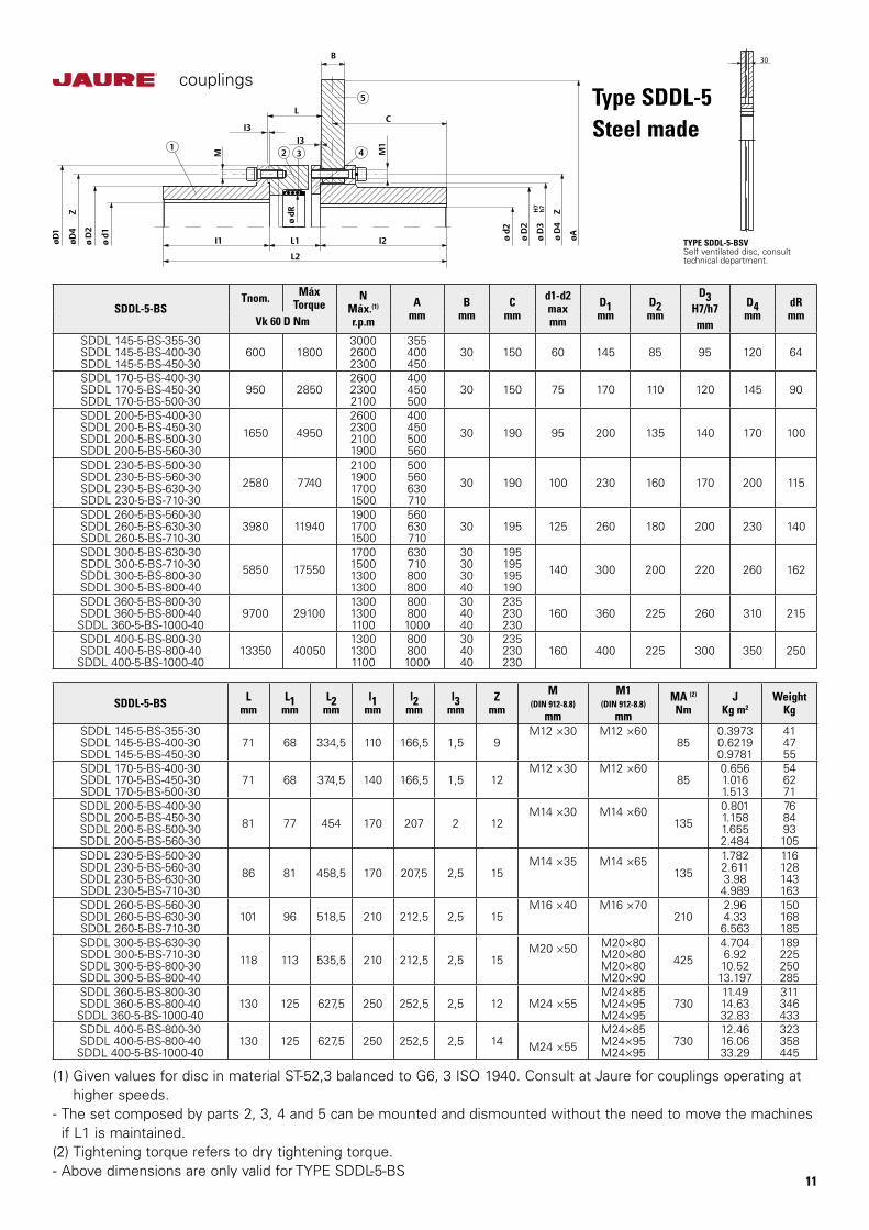
(1) Given values for disc in material ST-52,3 balanced to G6, 3 ISO 1940. Consult at Jaure for couplings operating at higher speeds.- The set composed by parts 2, 3, 4 and 5 can be mounted and dismounted without the need to move the machines if L1 is maintained.(2) Tightening torque refers to dry tightening torque.- Above dimensions are only valid for TYPE SDDL-5-BS
SDDL-5-BSTnom. Máx
TorqueN
Máx.(1)
r.p.m
Amm
Bmm
Cmm
d1-d2maxmm
D1mm
D2mm
D3H7/h7mm
D4mm
dRmmVk 60 D Nm
SDDL 145-5-BS-355-30SDDL 145-5-BS-400-30SDDL 145-5-BS-450-30
600 1800300026002300
355400450
30 150 60 145 85 95 120 64
SDDL 170-5-BS-400-30SDDL 170-5-BS-450-30SDDL 170-5-BS-500-30
950 2850260023002100
400450500
30 150 75 170 110 120 145 90
SDDL 200-5-BS-400-30SDDL 200-5-BS-450-30SDDL 200-5-BS-500-30SDDL 200-5-BS-560-30
1650 49502600230021001900
400450500560
30 190 95 200 135 140 170 100
SDDL 230-5-BS-500-30SDDL 230-5-BS-560-30SDDL 230-5-BS-630-30SDDL 230-5-BS-710-30
2580 77402100190017001500
500560630710
30 190 100 230 160 170 200 115
SDDL 260-5-BS-560-30SDDL 260-5-BS-630-30SDDL 260-5-BS-710-30
3980 11940190017001500
560630710
30 195 125 260 180 200 230 140
SDDL 300-5-BS-630-30SDDL 300-5-BS-710-30SDDL 300-5-BS-800-30SDDL 300-5-BS-800-40
5850 175501700150013001300
630710800800
30303040
195195195190
140 300 200 220 260 162
SDDL 360-5-BS-800-30SDDL 360-5-BS-800-40SDDL 360-5-BS-1000-40
9700 29100130013001100
8008001000
304040
235230230
160 360 225 260 310 215
SDDL 400-5-BS-800-30SDDL 400-5-BS-800-40SDDL 400-5-BS-1000-40
13350 40050130013001100
8008001000
304040
235230230
160 400 225 300 350 250
SDDL-5-BS Lmm
L1mm
L2mm
l1mm
l2mm
l3mm
Zmm
M(DIN 912-8.8)
mm
M1(DIN 912-8.8)
mm
MA (2)
NmJ
Kg m2Weight
Kg
SDDL 145-5-BS-355-30SDDL 145-5-BS-400-30SDDL 145-5-BS-450-30
71 68 334,5 110 166,5 1,5 9M12 ×30 M12 ×60
850.39730.62190.9781
414755
SDDL 170-5-BS-400-30SDDL 170-5-BS-450-30SDDL 170-5-BS-500-30
71 68 374,5 140 166,5 1,5 12M12 ×30 M12 ×60
850.6561.0161.513
546271
SDDL 200-5-BS-400-30SDDL 200-5-BS-450-30SDDL 200-5-BS-500-30SDDL 200-5-BS-560-30
81 77 454 170 207 2 12M14 ×30 M14 ×60
1350.8011.1581.6552.484
768493105
SDDL 230-5-BS-500-30SDDL 230-5-BS-560-30SDDL 230-5-BS-630-30SDDL 230-5-BS-710-30
86 81 458,5 170 207,5 2,5 15M14 ×35 M14 ×65
1351.7822.6113.984.989
116128143163
SDDL 260-5-BS-560-30SDDL 260-5-BS-630-30SDDL 260-5-BS-710-30
101 96 518,5 210 212,5 2,5 15M16 ×40 M16 ×70
2102.964.336.563
150168185
SDDL 300-5-BS-630-30SDDL 300-5-BS-710-30SDDL 300-5-BS-800-30SDDL 300-5-BS-800-40
118 113 535,5 210 212,5 2,5 15M20 ×50 M20×80
M20×80M20×80M20×90
4254.7046.9210.5213.197
189225250285
SDDL 360-5-BS-800-30SDDL 360-5-BS-800-40SDDL 360-5-BS-1000-40
130 125 627,5 250 252,5 2,5 12 M24 ×55M24×85M24×95M24×95
73011.4914.6332.83
311346433
SDDL 400-5-BS-800-30SDDL 400-5-BS-800-40SDDL 400-5-BS-1000-40
130 125 627,5 250 252,5 2,5 14 M24 ×55M24×85M24×95M24×95
73012.4616.0633.29
323358445
Type SDDL-5Steel made
TYPE SDDL-5-BSVSelf ventilated disc, consulttechnical department.
B
C
ø d
2
ø D
2
ø D
3
ø D
4
Z
øA
H7
h7
I1 L1 I2
L2
ø d
R
M1I3
L
I3
M
øD
1
øD
4
Z
ø d
1
ø D
2
12 3 4
5
30
couplings
12
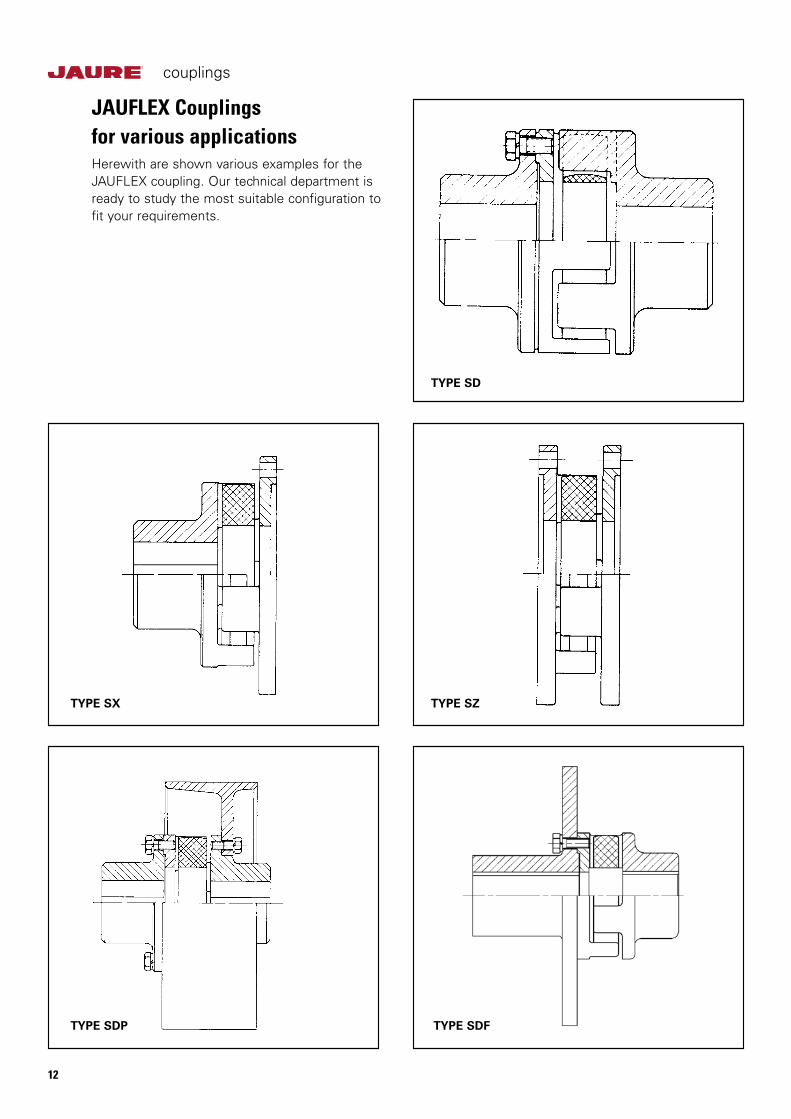
TYPE SD
TYPE SZTYPE SX
TYPE SDP TYPE SDF
JAUFLEX Couplingsfor various applicationsHerewith are shown various examples for the JAUFLEX coupling. Our technical department is ready to study the most suitable configuration to fit your requirements.
couplings
13
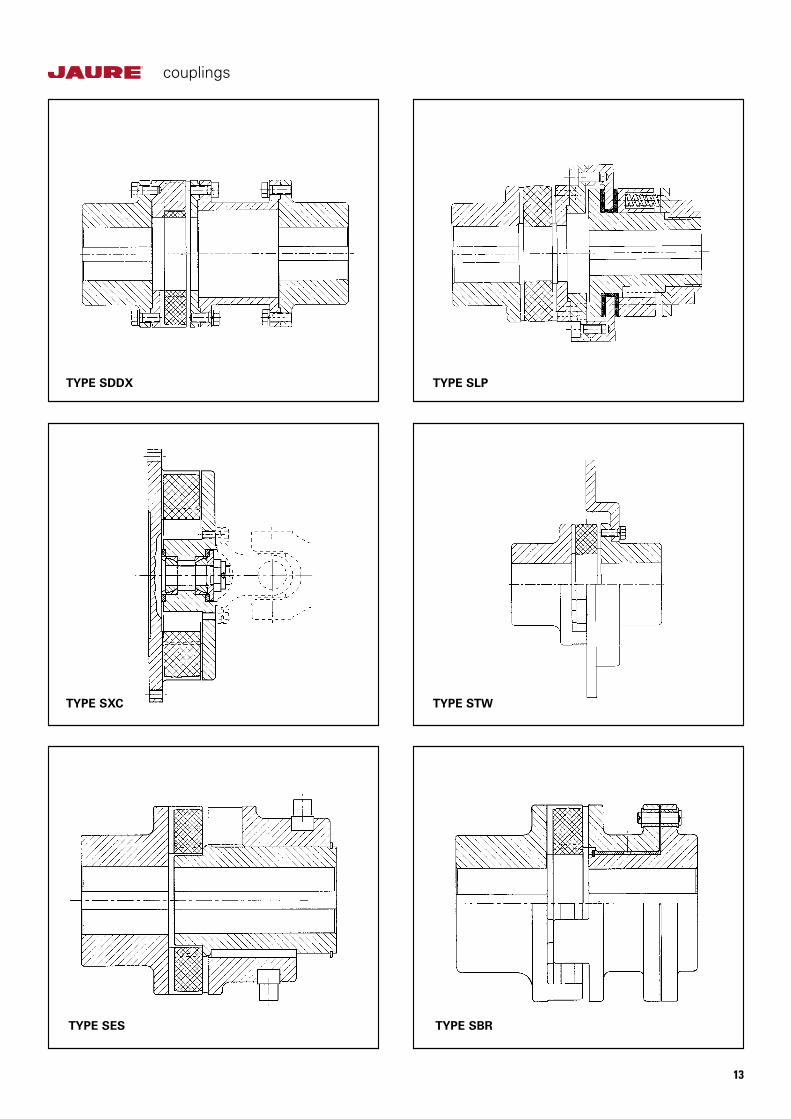
TYPE SDDX TYPE SLP
TYPE SXC TYPE STW
TYPE SES TYPE SBR

couplings
14
* Hub material has to have minimum 350 N/mm2 yield point. Other types of fitting can be performed as shown in the examples below.
Type of fit Shafttolerances
Boretolerances
Interferencefits withparallel
key
h 6 S 7
k 6 M 7
m 6 K 7
n 6 J 7
p 6 H 7
Shrink fits*withoutparallel
key
u 6
H 7v 6
x 6
Assembly with spline shaft
Assembly with locking devices
Assembly with shrink fit
Coupling fittingThe following recommendations, according to ISO, are given for shaft/bore fits.
couplings
15
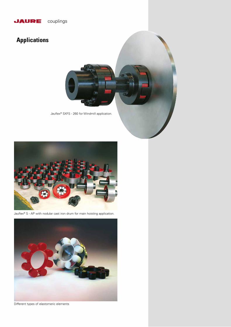
Jauflex® SXFS - 260 for Windmill application.
Jauflex® S - AP with nodular cast iron drum for main hoisting application.
Different types of elastomeric elements
Applications
APPLICATION CONSIDERATIONS
The proper selection and application of power transmission products and components, including the related area of product safety, is the responsibility of the customer. Operating and performance requirements and potential associated issues will vary appreciably depending upon the use and application of such products and components. The scope of the technical and application informa-tion included in this publication is necessarily limited. Unusual operating environments and conditions, lubrication requirements, loading supports, and other factors can materially affect the application and operating results of the products and components and the customer should carefully review its requirements. Any technical advice or review furnished by Regal Beloit America, Inc. and its affiliates with respect to the use of products and components is given in good faith and without charge, and Regal assumes no obligation or liability for the advice given, or results obtained, all such advice and review being given and accepted at customer’s risk.
For a copy of our Standard Terms and Conditions of Sale, Disclaimers of Warranty, Limitation of Liability and Remedy, please contact Customer Service at 1-800-626-2120. These terms and conditions of sale, disclaimers and limitations of liability apply to any person who may buy, acquire or use a Regal Beloit America Inc. product referred to herein, including any person who buys from a licensed distributor of these branded products.
Regal Power Transmission Solutions7120 New Buffington RoadFlorence, KY 41042Customer Service: 800-626-2120Fax: 800-262-3292Technical Service: 800-626-2093
www.RegalPTS.com
Jaure, Jauflex and Regal are trademarks of Regal Beloit Corporation or one of its affiliated companies.
©2016 Regal Beloit Corporation, All Rights Reserved. MCB16034E • Form# 9513E • Printed in USA