Embed Size (px)
Citation preview
Jammed-array wideband sawtooth filter
Zhongwei Tan,1,2
Chao Wang,2 Keisuke Goda,
2,3,4,* Omer Malik,
2 and Bahram Jalali
2,3,4,5
1Institute of Lightwave Technology, Key Lab of All Optical Network & Advanced Telecommunication Network of
EMC, Beijing Jiaotong University, Beijing 100044, China 2Electrical Engineering Department, University of California, Los Angeles, CA 90095, USA
3California NanoSystems Institute, Los Angeles, CA 90095, USA 4Department of Bioengineering, University of California, Los Angeles, CA 90095, USA
5Department of Surgery, David Geffen School of Medicine, University of California, Los Angeles, CA 90095, USA *[email protected]
Abstract: We present an all-optical passive low-cost spectral filter that
exhibits a high-resolution periodic sawtooth spectral pattern without the
need for active optoelectronic components. The principle of the filter is the
partial masking of a phased array of virtual light sources with multiply
jammed diffraction orders. We utilize the filter’s periodic linear map
between frequency and intensity to demonstrate fast sensitive interrogation
of fiber Bragg grating sensor arrays and ultrahigh-frequency electrical
sawtooth waveform generation.
© 2011 Optical Society of America
OCIS codes: (280.0280) Remote sensing and sensors; (120.2440) Filters
References and links
1. H. A. Macleod, Thin-film optical filters (CRC Press, 2010)
2. G. Z. Xiao, P. Zhao, F. G. Sun, Z. G. Lu, Z. Zhang, and C. P. Grover, “Interrogating fiber Bragg grating sensors
by thermally scanning a demultiplexer based on arrayed waveguide gratings,” Opt. Lett. 29(19), 2222–2224
(2004).
3. S. Baskar, P. N. Suganthan, N. Q. Ngo, A. Alphones, and R. T. Zheng, “Design of triangular FBG filter for
sensor applications using covariance matrix adapted evolution algorithm,” Opt. Commun. 260(2), 716–722
(2006).
4. S. Bandyopadhyay, P. Biswas, A. Pal, S. K. Bhadra, and K. Dasgupta, “Empirical relations for design of linear
edge filters using apodized linearly chirped fiber Bragg grating,” J. Lightwave Technol. 26(24), 3853–3859
(2008).
5. A. M. Weiner, “Femtosecond pulse shaping using spatial light modulators,” Rev. Sci. Instrum. 71(5), 1929–1960
(2000).
6. M. Shirasaki, “Large angular dispersion by a virtually imaged phased array and its application to a wavelength
demultiplexer,” Opt. Lett. 21(5), 366–368 (1996).
7. S. Xiao, A. M. Weiner, and C. L. Lin, “A dispersion law for virtually imaged phased array spectral dispersers
based on paraxial wave theory,” IEEE J. Quantum Electron. 40(4), 420–426 (2004).
8. K. Goda, K. K. Tsia, and B. Jalali, “Serial time-encoded amplified imaging for real-time observation of fast
dynamic phenomena,” Nature 458(7242), 1145–1149 (2009).
9. D. Chen, C. Shu, and S. He, “Multiple fiber Bragg grating interrogation based on a spectrum-limited Fourier
domain mode-locking fiber laser,” Opt. Lett. 33(13), 1395–1397 (2008).
10. H. Xia, C. Wang, S. Blais, and J. Yao, “Ultrafast and precise interrogation of fiber Bragg grating sensor based on
wavelength-to-time mapping incorporating higher order dispersion,” J. Lightwave Technol. 28(3), 254–261
(2010).
11. J. H. Reed, An introduction to ultra wideband communication systems (Prentice-Hall, 2005)
12. B. Jalali, P. V. Kelkar, and V. Saxena, “Photonic arbitrary waveform generator,” Proc. Lasers Electro-Opt. Soc.
1, 253–254 (2001).
1. Introduction
Technological advances in fabrication of high-quality optical elements for the past few
decades have enabled the widespread use of low-cost optical filters [1]. Currently, various
types of optical filters are commercially available, such as neutral density filters, dichroic
filters, and band-pass filters, for numerous applications including optical communications,
astronomy, defense, remote sensing, and biomedical imaging [1]. The performance in many
of these systems is intimately tied to the capabilities of optical filters.
#153359 - $15.00 USD Received 25 Aug 2011; revised 7 Oct 2011; accepted 9 Oct 2011; published 16 Nov 2011(C) 2011 OSA 21 November 2011 / Vol. 19, No. 24 / OPTICS EXPRESS 24563
Optical filters with complex spectral response are useful for a broad range of applications
such as spectroscopy, pulse shaping, waveform generation, fiber Bragg grating (FBG)
sensors, and optical communication systems. For example, a periodic sawtooth filter is
important as it can serve as an edge filter array for fast sensitive interrogation of a FBG sensor
array and multi-channel wavelength monitoring in dense wavelength-division multiplexing
(WDM) optical communication systems [2]. Unfortunately, such complex filters are difficult
to build with passive optical components due to limitations of fabrication technology that
prohibit design of required parameters. While efforts have been made to produce sawtooth
spectral response, previously reported methods [3, 4] fall short of the requirements for large
bandwidth, periodicity, high duty cycle, and linearity. Alternatively, the periodic sawtooth
filter response can be achieved by using active optoelectronic components such as a spatial
light modulator sandwiched between a pair of diffraction gratings [5], but their costs are
typically high, limiting practical use.
In this paper, we propose and demonstrate a simple all-optical passive low-cost spectral
filter that exhibits a high-resolution periodic sawtooth spectral pattern without the need for
active optoelectronic components. The filter builds on an integration of a virtually-imaged
phased array (VIPA) [6–8] and intensity mask along with two lenses and hence consists of
totally passive optical components with a low cost. Designed to be a side-entrance Fabry-
Perot etalon with a carefully tuned angle of incidence, the VIPA behaves as a spatial disperser
(analogous to a prism or diffraction grating) yet with multiple diffraction orders that overlap
with each other. In other words, the VIPA produces a phased array of virtual light sources that
consists of multiply “jammed” diffraction orders of wideband light. Consequently, when the
phased array is partially masked, a high-resolution periodic sawtooth-shaped spectrum or a
series of linearly sloping edges is produced. To show the utility of the filter, we demonstrate
its application to fast sensitive interrogation of FBG sensor arrays and ultrahigh-frequency
electrical sawtooth waveform generation.
Fig. 1. JAWS filter. (a) Schematic. The dispersed light with spatially overlapped degenerate
FSRs interferes in the Fourier plane at the intensity mask. The returned light exhibits a periodic
sawtooth spectral pattern. (b) Simulation of the mapping relation between the wavelength and
diffraction angle. (c) Simulation of the filter response: when the area of x < 0 is masked (top)
and when the area of x > 0 is masked (bottom).
2. Jammed-array wideband sawtooth (JAWS) filter
The concept of the filter which we refer to ask the jammed-array wideband sawtooth (JAWS)
filter is depicted in Fig. 1. The primary components of the filter are the VIPA and intensity
mask. As shown in Fig. 1a, a collimated broadband light is focused with a cylindrical lens into
#153359 - $15.00 USD Received 25 Aug 2011; revised 7 Oct 2011; accepted 9 Oct 2011; published 16 Nov 2011(C) 2011 OSA 21 November 2011 / Vol. 19, No. 24 / OPTICS EXPRESS 24564
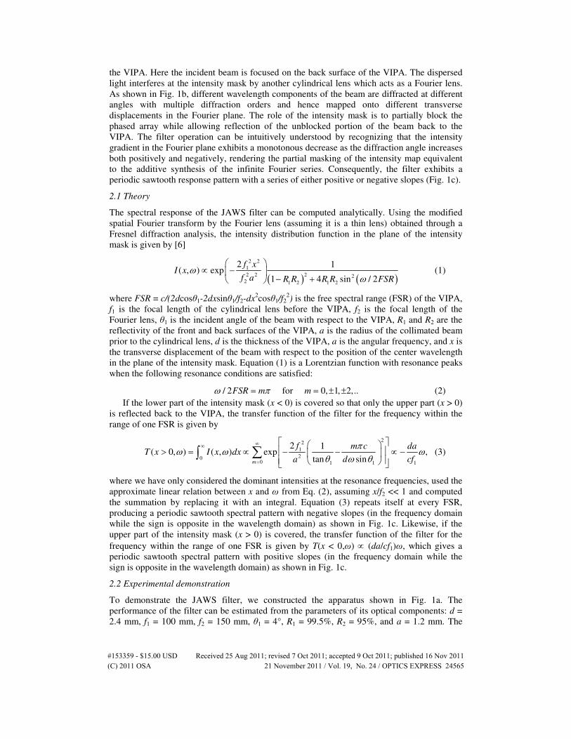
the VIPA. Here the incident beam is focused on the back surface of the VIPA. The dispersed
light interferes at the intensity mask by another cylindrical lens which acts as a Fourier lens.
As shown in Fig. 1b, different wavelength components of the beam are diffracted at different
angles with multiple diffraction orders and hence mapped onto different transverse
displacements in the Fourier plane. The role of the intensity mask is to partially block the
phased array while allowing reflection of the unblocked portion of the beam back to the
VIPA. The filter operation can be intuitively understood by recognizing that the intensity
gradient in the Fourier plane exhibits a monotonous decrease as the diffraction angle increases
both positively and negatively, rendering the partial masking of the intensity map equivalent
to the additive synthesis of the infinite Fourier series. Consequently, the filter exhibits a
periodic sawtooth response pattern with a series of either positive or negative slopes (Fig. 1c).
2.1 Theory
The spectral response of the JAWS filter can be computed analytically. Using the modified
spatial Fourier transform by the Fourier lens (assuming it is a thin lens) obtained through a
Fresnel diffraction analysis, the intensity distribution function in the plane of the intensity
mask is given by [6]
( ) ( )
2 2
1
2 2 2 22 1 2 1 2
2 1( , ) exp
1 4 sin / 2
f xI x
f a R R R R FSRω
ω
∝ −
− + (1)
where FSR = c/(2dcosθ1-2dxsinθ1/f2-dx2cosθ1/f2
2) is the free spectral range (FSR) of the VIPA,
f1 is the focal length of the cylindrical lens before the VIPA, f2 is the focal length of the
Fourier lens, θ1 is the incident angle of the beam with respect to the VIPA, R1 and R2 are the
reflectivity of the front and back surfaces of the VIPA, a is the radius of the collimated beam
prior to the cylindrical lens, d is the thickness of the VIPA, a is the angular frequency, and x is
the transverse displacement of the beam with respect to the position of the center wavelength
in the plane of the intensity mask. Equation (1) is a Lorentzian function with resonance peaks
when the following resonance conditions are satisfied:
/ 2 for 0, 1, 2,..FSR m mω π= = ± ± (2)
If the lower part of the intensity mask (x < 0) is covered so that only the upper part (x > 0)
is reflected back to the VIPA, the transfer function of the filter for the frequency within the
range of one FSR is given by
22
1
200 1 1 1
2 1( 0, ) ( , ) exp ,
tan sinm
f m c daT x I x dx
d cfa
πω ω ω
θ ω θ
∞∞
=
> = ∝ − − ∝ −
∑∫ (3)
where we have only considered the dominant intensities at the resonance frequencies, used the
approximate linear relation between x and ω from Eq. (2), assuming x/f2 << 1 and computed
the summation by replacing it with an integral. Equation (3) repeats itself at every FSR,
producing a periodic sawtooth spectral pattern with negative slopes (in the frequency domain
while the sign is opposite in the wavelength domain) as shown in Fig. 1c. Likewise, if the
upper part of the intensity mask (x > 0) is covered, the transfer function of the filter for the
frequency within the range of one FSR is given by T(x < 0,ω) ∝ (da/cf1)ω, which gives a
periodic sawtooth spectral pattern with positive slopes (in the frequency domain while the
sign is opposite in the wavelength domain) as shown in Fig. 1c.
2.2 Experimental demonstration
To demonstrate the JAWS filter, we constructed the apparatus shown in Fig. 1a. The
performance of the filter can be estimated from the parameters of its optical components: d =
2.4 mm, f1 = 100 mm, f2 = 150 mm, θ1 = 4°, R1 = 99.5%, R2 = 95%, and a = 1.2 mm. The
#153359 - $15.00 USD Received 25 Aug 2011; revised 7 Oct 2011; accepted 9 Oct 2011; published 16 Nov 2011(C) 2011 OSA 21 November 2011 / Vol. 19, No. 24 / OPTICS EXPRESS 24565
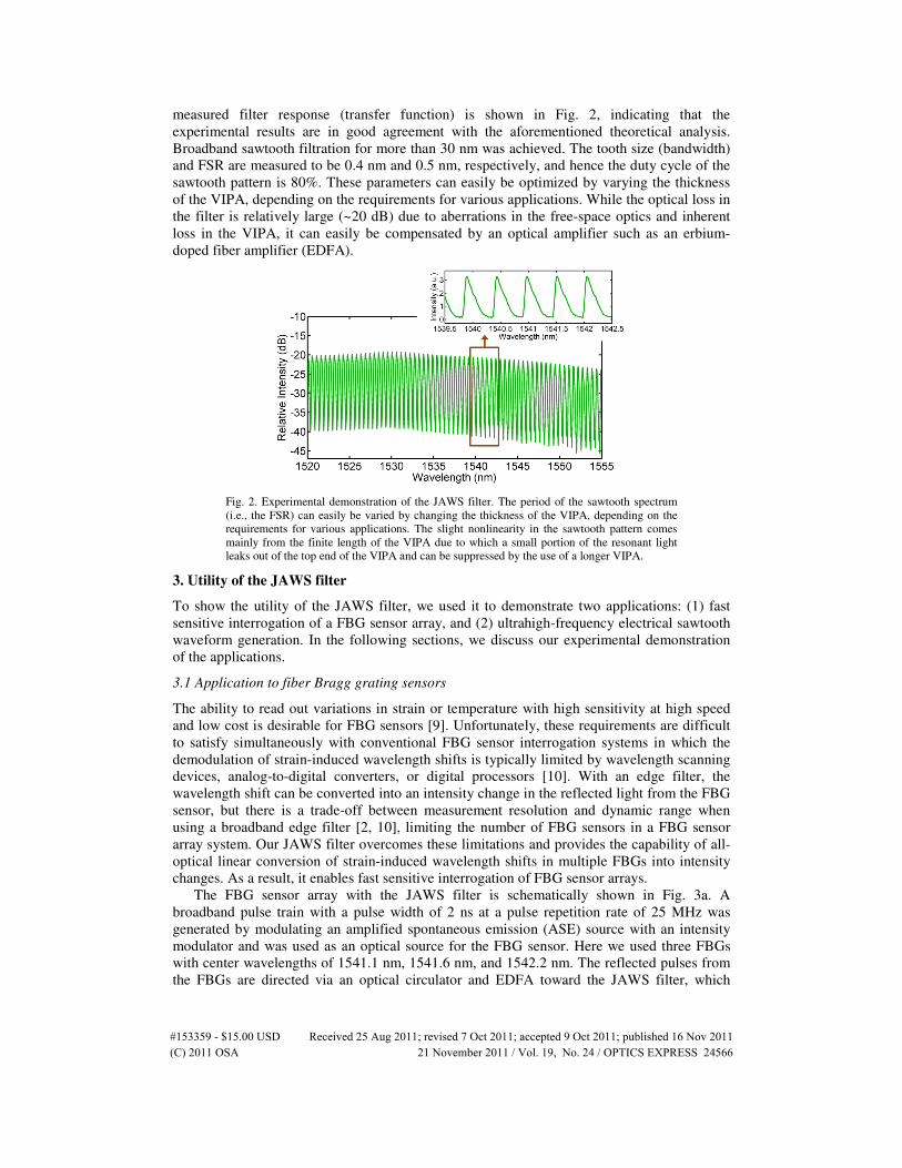
measured filter response (transfer function) is shown in Fig. 2, indicating that the
experimental results are in good agreement with the aforementioned theoretical analysis.
Broadband sawtooth filtration for more than 30 nm was achieved. The tooth size (bandwidth)
and FSR are measured to be 0.4 nm and 0.5 nm, respectively, and hence the duty cycle of the
sawtooth pattern is 80%. These parameters can easily be optimized by varying the thickness
of the VIPA, depending on the requirements for various applications. While the optical loss in
the filter is relatively large (~20 dB) due to aberrations in the free-space optics and inherent
loss in the VIPA, it can easily be compensated by an optical amplifier such as an erbium-
doped fiber amplifier (EDFA).
Fig. 2. Experimental demonstration of the JAWS filter. The period of the sawtooth spectrum
(i.e., the FSR) can easily be varied by changing the thickness of the VIPA, depending on the
requirements for various applications. The slight nonlinearity in the sawtooth pattern comes
mainly from the finite length of the VIPA due to which a small portion of the resonant light
leaks out of the top end of the VIPA and can be suppressed by the use of a longer VIPA.
3. Utility of the JAWS filter
To show the utility of the JAWS filter, we used it to demonstrate two applications: (1) fast
sensitive interrogation of a FBG sensor array, and (2) ultrahigh-frequency electrical sawtooth
waveform generation. In the following sections, we discuss our experimental demonstration
of the applications.
3.1 Application to fiber Bragg grating sensors
The ability to read out variations in strain or temperature with high sensitivity at high speed
and low cost is desirable for FBG sensors [9]. Unfortunately, these requirements are difficult
to satisfy simultaneously with conventional FBG sensor interrogation systems in which the
demodulation of strain-induced wavelength shifts is typically limited by wavelength scanning
devices, analog-to-digital converters, or digital processors [10]. With an edge filter, the
wavelength shift can be converted into an intensity change in the reflected light from the FBG
sensor, but there is a trade-off between measurement resolution and dynamic range when
using a broadband edge filter [2, 10], limiting the number of FBG sensors in a FBG sensor
array system. Our JAWS filter overcomes these limitations and provides the capability of all-
optical linear conversion of strain-induced wavelength shifts in multiple FBGs into intensity
changes. As a result, it enables fast sensitive interrogation of FBG sensor arrays.
The FBG sensor array with the JAWS filter is schematically shown in Fig. 3a. A
broadband pulse train with a pulse width of 2 ns at a pulse repetition rate of 25 MHz was
generated by modulating an amplified spontaneous emission (ASE) source with an intensity
modulator and was used as an optical source for the FBG sensor. Here we used three FBGs
with center wavelengths of 1541.1 nm, 1541.6 nm, and 1542.2 nm. The reflected pulses from
the FBGs are directed via an optical circulator and EDFA toward the JAWS filter, which
#153359 - $15.00 USD Received 25 Aug 2011; revised 7 Oct 2011; accepted 9 Oct 2011; published 16 Nov 2011(C) 2011 OSA 21 November 2011 / Vol. 19, No. 24 / OPTICS EXPRESS 24566
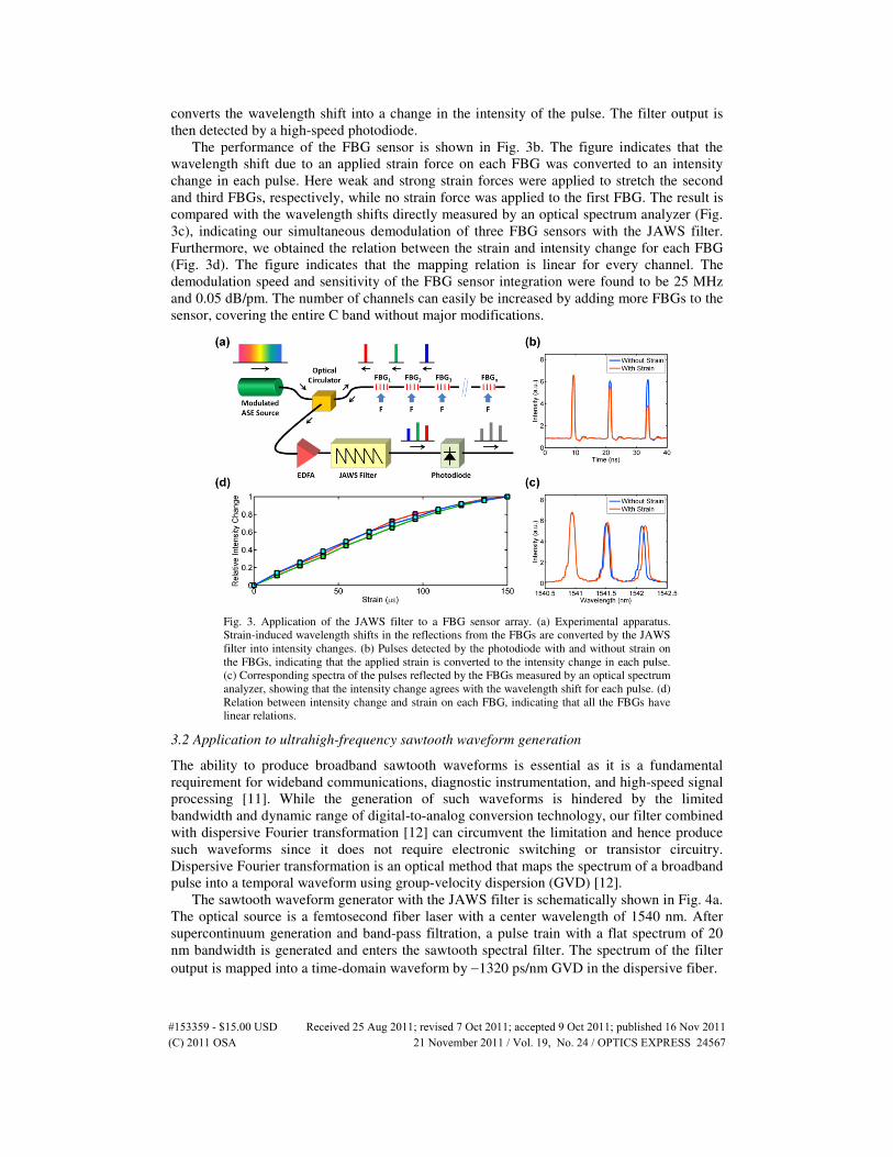
converts the wavelength shift into a change in the intensity of the pulse. The filter output is
then detected by a high-speed photodiode.
The performance of the FBG sensor is shown in Fig. 3b. The figure indicates that the
wavelength shift due to an applied strain force on each FBG was converted to an intensity
change in each pulse. Here weak and strong strain forces were applied to stretch the second
and third FBGs, respectively, while no strain force was applied to the first FBG. The result is
compared with the wavelength shifts directly measured by an optical spectrum analyzer (Fig.
3c), indicating our simultaneous demodulation of three FBG sensors with the JAWS filter.
Furthermore, we obtained the relation between the strain and intensity change for each FBG
(Fig. 3d). The figure indicates that the mapping relation is linear for every channel. The
demodulation speed and sensitivity of the FBG sensor integration were found to be 25 MHz
and 0.05 dB/pm. The number of channels can easily be increased by adding more FBGs to the
sensor, covering the entire C band without major modifications.
Fig. 3. Application of the JAWS filter to a FBG sensor array. (a) Experimental apparatus.
Strain-induced wavelength shifts in the reflections from the FBGs are converted by the JAWS
filter into intensity changes. (b) Pulses detected by the photodiode with and without strain on
the FBGs, indicating that the applied strain is converted to the intensity change in each pulse.
(c) Corresponding spectra of the pulses reflected by the FBGs measured by an optical spectrum
analyzer, showing that the intensity change agrees with the wavelength shift for each pulse. (d)
Relation between intensity change and strain on each FBG, indicating that all the FBGs have
linear relations.
3.2 Application to ultrahigh-frequency sawtooth waveform generation
The ability to produce broadband sawtooth waveforms is essential as it is a fundamental
requirement for wideband communications, diagnostic instrumentation, and high-speed signal
processing [11]. While the generation of such waveforms is hindered by the limited
bandwidth and dynamic range of digital-to-analog conversion technology, our filter combined
with dispersive Fourier transformation [12] can circumvent the limitation and hence produce
such waveforms since it does not require electronic switching or transistor circuitry.
Dispersive Fourier transformation is an optical method that maps the spectrum of a broadband
pulse into a temporal waveform using group-velocity dispersion (GVD) [12].
The sawtooth waveform generator with the JAWS filter is schematically shown in Fig. 4a.
The optical source is a femtosecond fiber laser with a center wavelength of 1540 nm. After
supercontinuum generation and band-pass filtration, a pulse train with a flat spectrum of 20
nm bandwidth is generated and enters the sawtooth spectral filter. The spectrum of the filter
output is mapped into a time-domain waveform by −1320 ps/nm GVD in the dispersive fiber.
#153359 - $15.00 USD Received 25 Aug 2011; revised 7 Oct 2011; accepted 9 Oct 2011; published 16 Nov 2011(C) 2011 OSA 21 November 2011 / Vol. 19, No. 24 / OPTICS EXPRESS 24567
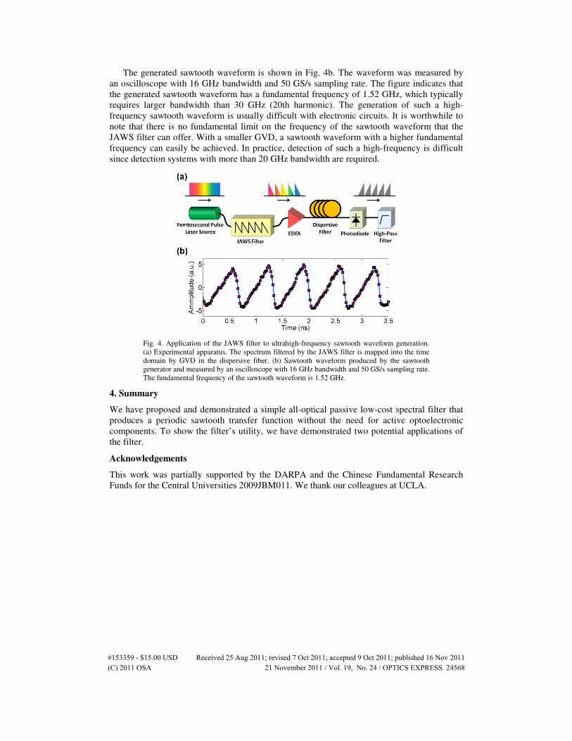
The generated sawtooth waveform is shown in Fig. 4b. The waveform was measured by
an oscilloscope with 16 GHz bandwidth and 50 GS/s sampling rate. The figure indicates that
the generated sawtooth waveform has a fundamental frequency of 1.52 GHz, which typically
requires larger bandwidth than 30 GHz (20th harmonic). The generation of such a high-
frequency sawtooth waveform is usually difficult with electronic circuits. It is worthwhile to
note that there is no fundamental limit on the frequency of the sawtooth waveform that the
JAWS filter can offer. With a smaller GVD, a sawtooth waveform with a higher fundamental
frequency can easily be achieved. In practice, detection of such a high-frequency is difficult
since detection systems with more than 20 GHz bandwidth are required.
Fig. 4. Application of the JAWS filter to ultrahigh-frequency sawtooth waveform generation.
(a) Experimental apparatus. The spectrum filtered by the JAWS filter is mapped into the time
domain by GVD in the dispersive fiber. (b) Sawtooth waveform produced by the sawtooth
generator and measured by an oscilloscope with 16 GHz bandwidth and 50 GS/s sampling rate.
The fundamental frequency of the sawtooth waveform is 1.52 GHz.
4. Summary
We have proposed and demonstrated a simple all-optical passive low-cost spectral filter that
produces a periodic sawtooth transfer function without the need for active optoelectronic
components. To show the filter’s utility, we have demonstrated two potential applications of
the filter.
Acknowledgements
This work was partially supported by the DARPA and the Chinese Fundamental Research
Funds for the Central Universities 2009JBM011. We thank our colleagues at UCLA.
#153359 - $15.00 USD Received 25 Aug 2011; revised 7 Oct 2011; accepted 9 Oct 2011; published 16 Nov 2011(C) 2011 OSA 21 November 2011 / Vol. 19, No. 24 / OPTICS EXPRESS 24568