Embed Size (px)
DESCRIPTION
JAMES F. JAKOBSEN GRADUATE FORUM 2003. STUDY ON CMS HF LIGHT-GUIDE SYSTEMS IN UNIVERSITY OF IOWA. By FIRDEVS DURU DEPARTMENT OF PHYSICS AND ASTRONOMY. OUTLINE. LHC project CMS experiment HF Calorimeter Light Guide Tests on: Materials (Al Mylar and HEM ) Shapes ( straight , tapered ) - PowerPoint PPT Presentation
Citation preview
JAMES F. JAKOBSEN GRADUATE FORUM 2003
STUDY ON CMS HF LIGHT-GUIDE SYSTEMS IN UNIVERSITY OF IOWA
ByFIRDEVS DURU
DEPARTMENT OF PHYSICS AND ASTRONOMY
OUTLINE
• LHC projectCMS experimentHF Calorimeter
• Light Guide Tests on:Materials (Al Mylar and HEM )
Shapes ( straight , tapered )Radiation hardness
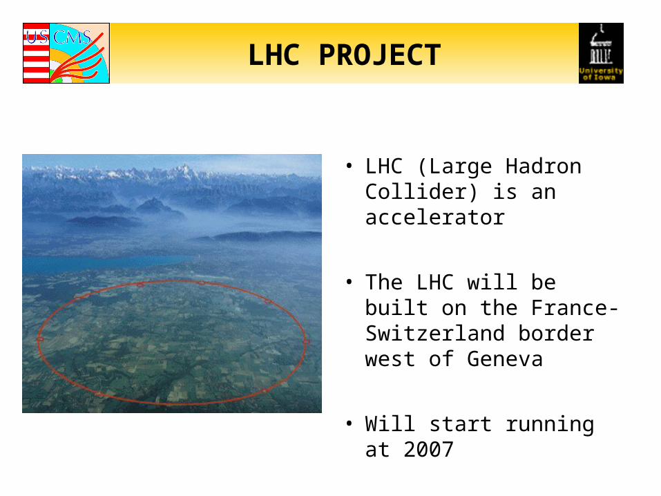
LHC PROJECT
• LHC (Large Hadron Collider) is an accelerator
• The LHC will be built on the France-Switzerland border west of Geneva
• Will start running at 2007
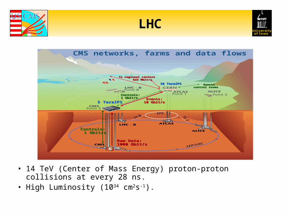
LHC
• 14 TeV (Center of Mass Energy) proton-proton collisions at every 28 ns. • High Luminosity (1034 cm2s-1).
Raw Data: 1000 Gbit/sRaw Data: 1000 Gbit/s
5 TeraIPS5 TeraIPSEvents:
10 Gbit/sEvents:
10 Gbit/s
10 TeraIPS10 TeraIPS
Controls: 1 Gbit/s
Controls: 1 Gbit/s
To regional centers 622 Mbit/s
To regional centers 622 Mbit/s
CMS networks, farms and data flows
Remote control rooms
Remote control rooms
Controls: 1 Gbit/sControls: 1 Gbit/s
CMS EXPERIMENT
• CMS (Compact Muon Solenoid) detector has been designed to detect cleanly the diverse signatures from new physics by identifying and precisely measuring muons, electrons and photons over a large energy range and at high luminosity.
• The main physics interests:Standard Model (SM) Higgs boson Minimum Supersymmetric Standard Model (MSSM) Higgs bosonsGluino, squark searches.
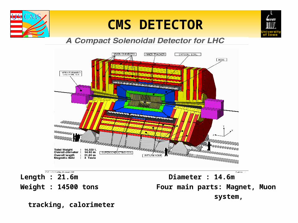
CMS DETECTOR
Length : 21.6m Diameter : 14.6m
Weight : 14500 tons Four main parts: Magnet, Muon
system, tracking, calorimeter
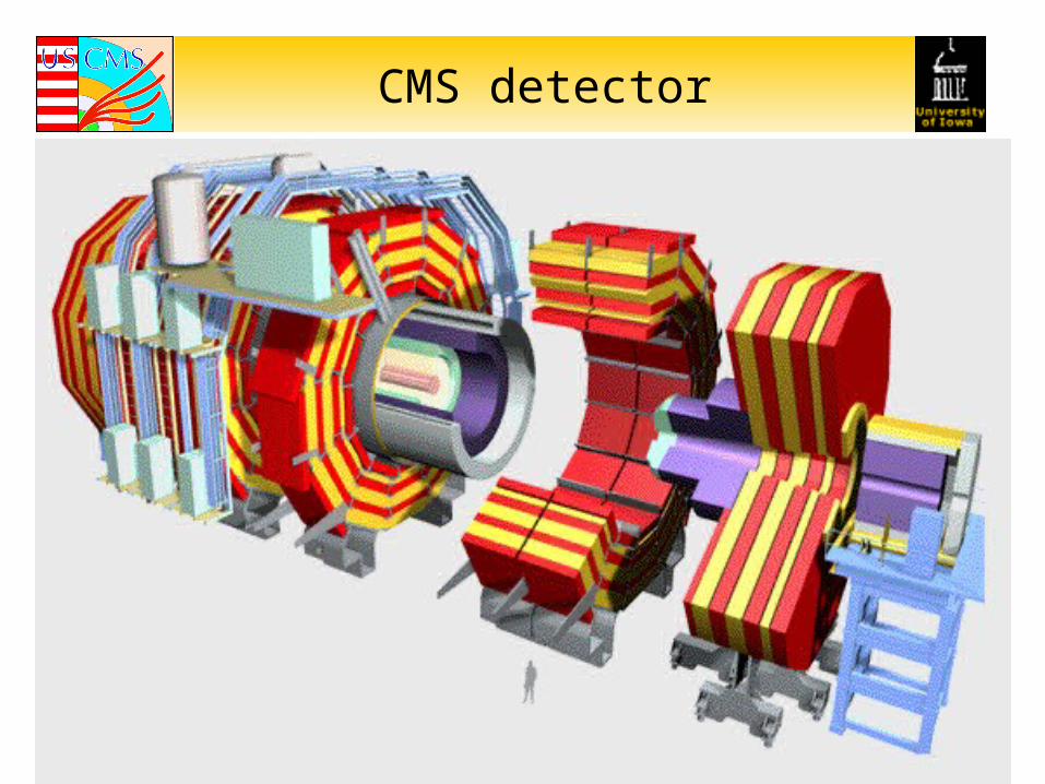
CMS detector
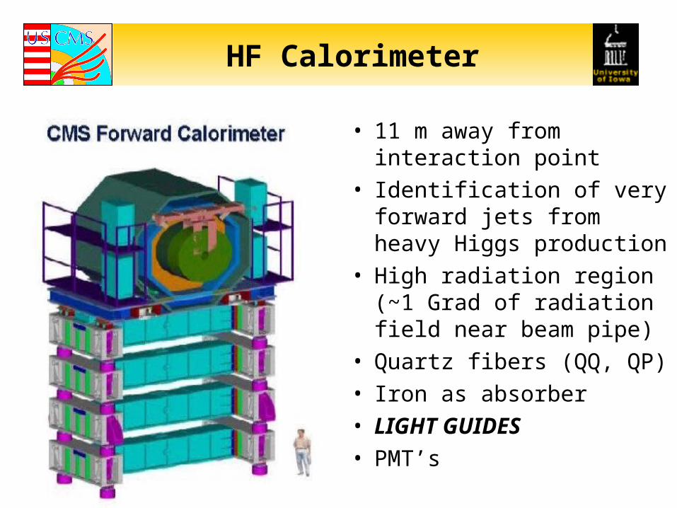
HF Calorimeter
• 11 m away from interaction point
• Identification of very forward jets from heavy Higgs production
• High radiation region (~1 Grad of radiation field near beam pipe)
• Quartz fibers (QQ, QP)
• Iron as absorber
• LIGHT GUIDES
• PMT’s
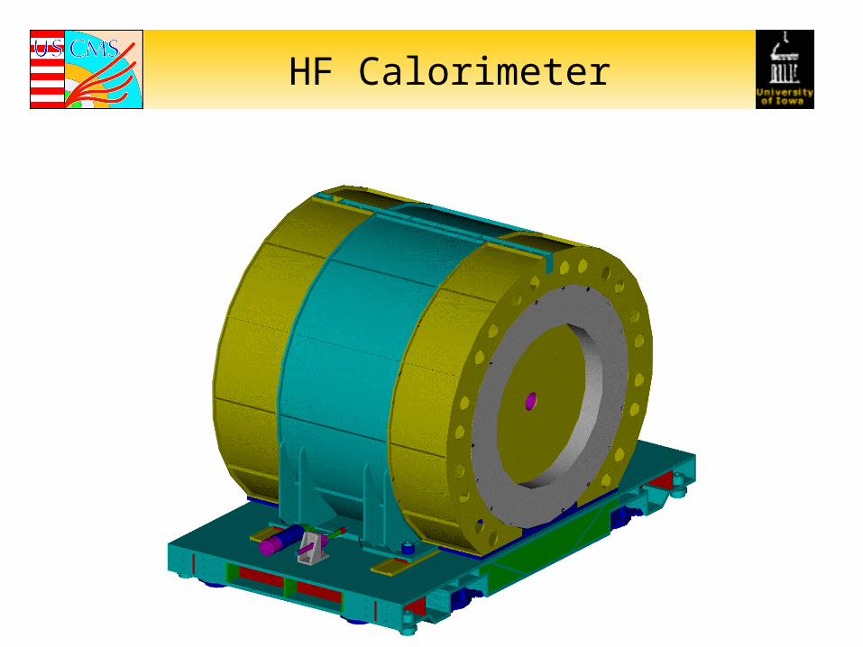
HF Calorimeter
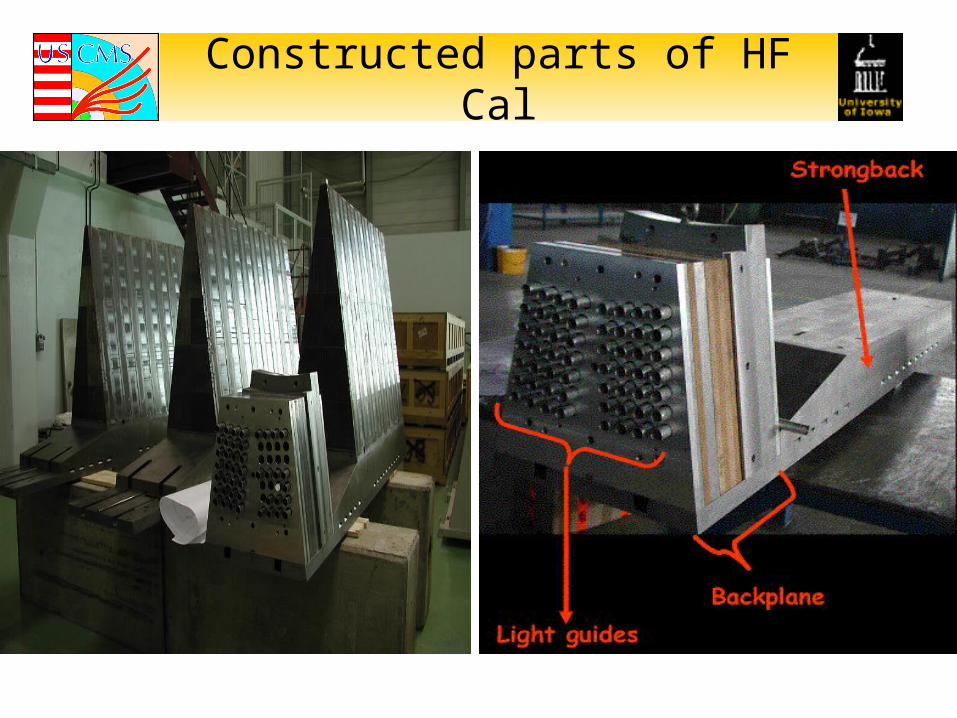
Constructed parts of HF Cal
PURPOSE OF THE LIGHT GUIDE TESTS
• Test the effect of the light guides on the uniformity of the PMT Signal by measuring the X-Y uniformity and attenuation[Optical properties – mixing]
• Comparison of the tapered light guides vs. non-tapered ones.
• Comparison of the different types of reflective materials (HEM, Al Mylar)
• Test the effect of radiation on two materials
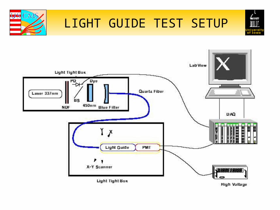
LIGHT GUIDE TEST SETUP
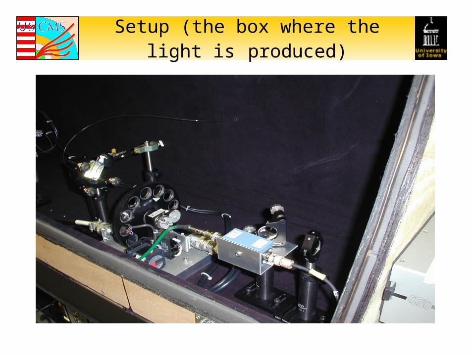
Setup (the box where the light is produced)
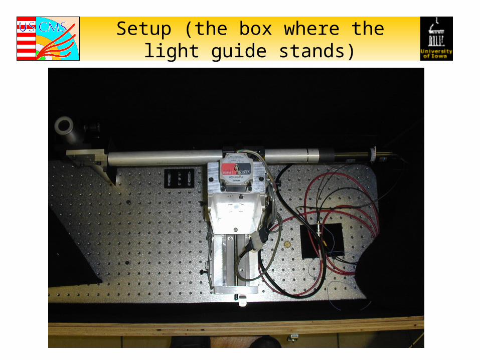
Setup (the box where the light guide stands)
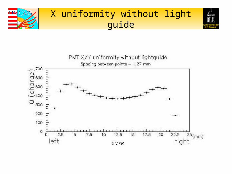
X uniformity without light guide
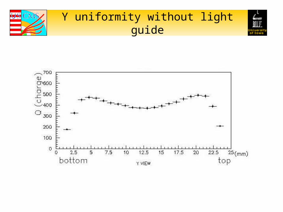
Y uniformity without light guide
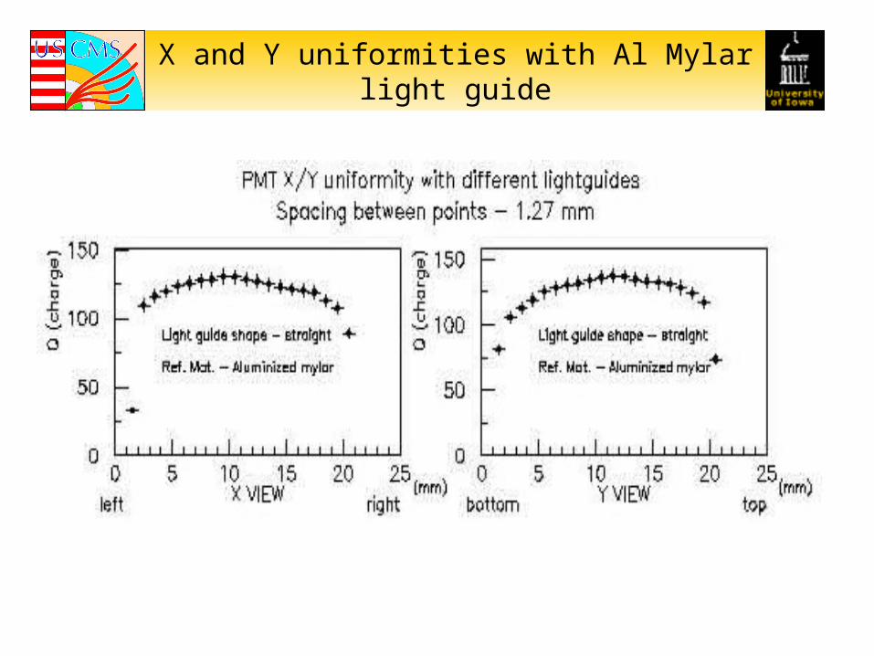
X and Y uniformities with Al Mylar light guide
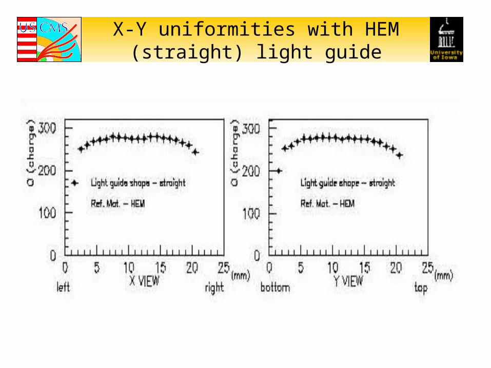
X-Y uniformities with HEM (straight) light guide
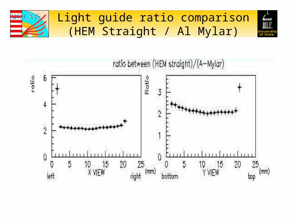
Light guide ratio comparison(HEM Straight / Al Mylar)
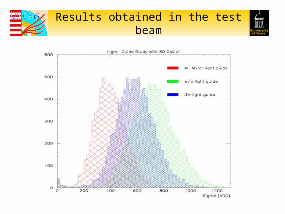
Results obtained in the test beam
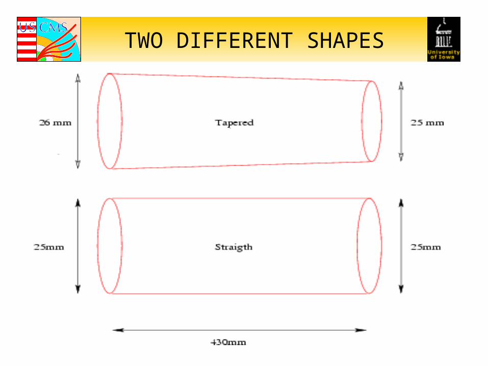
TWO DIFFERENT SHAPES
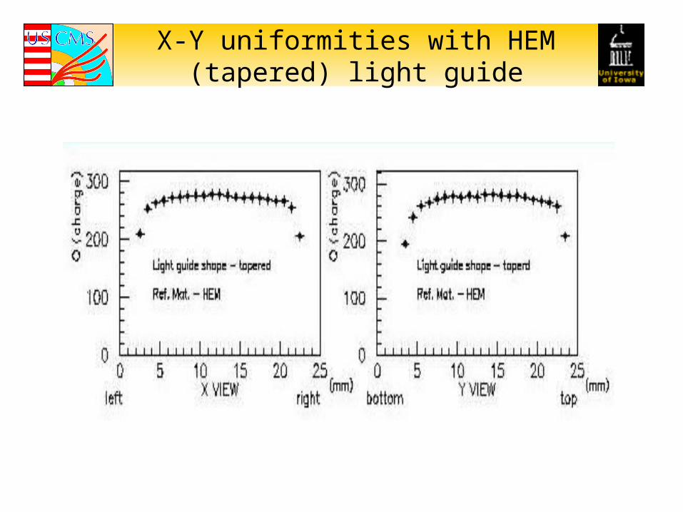
X-Y uniformities with HEM (tapered) light guide
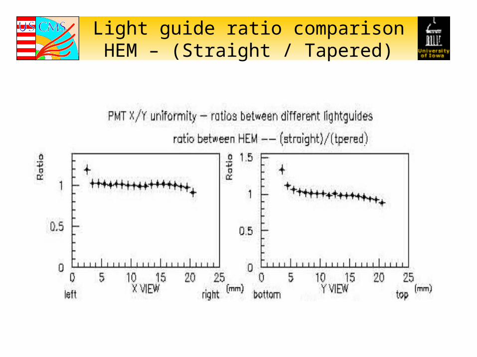
Light guide ratio comparisonHEM – (Straight / Tapered)
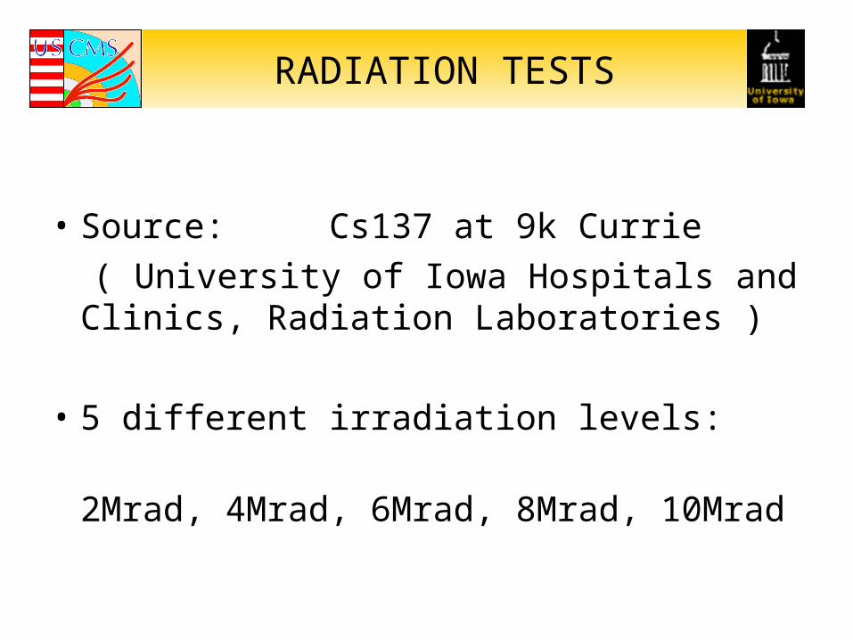
RADIATION TESTS
• Source: Cs137 at 9k Currie
( University of Iowa Hospitals and Clinics, Radiation Laboratories )
• 5 different irradiation levels:
2Mrad, 4Mrad, 6Mrad, 8Mrad, 10Mrad
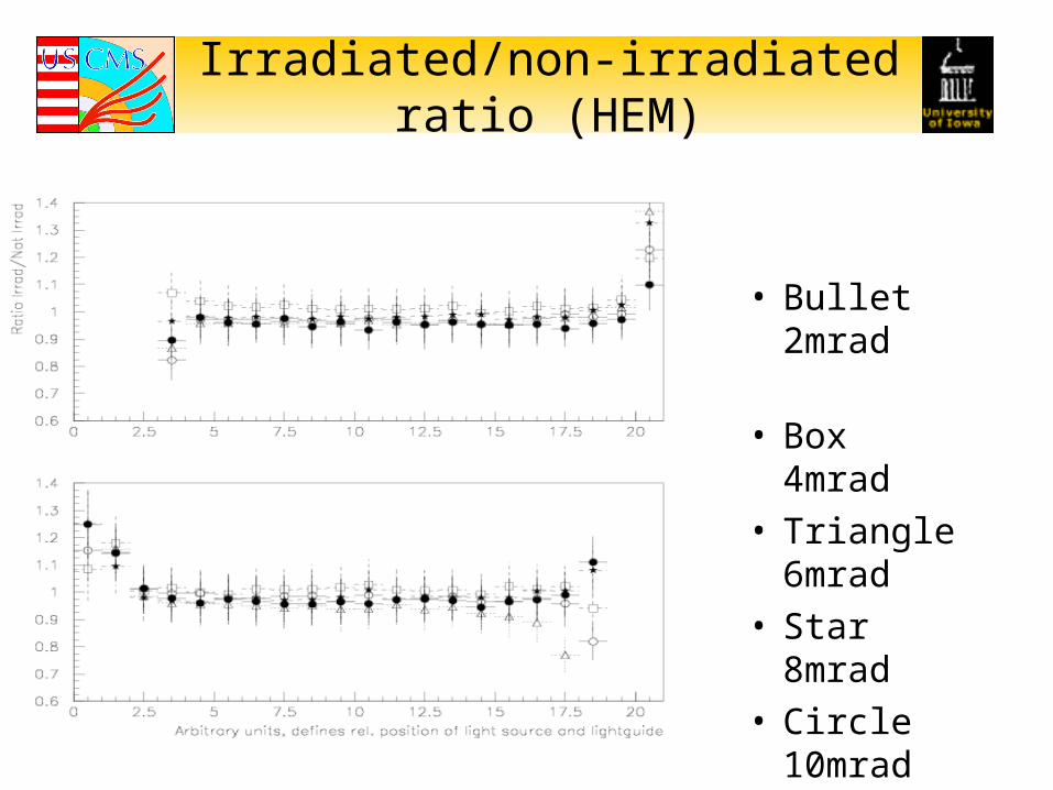
Irradiated/non-irradiated ratio (HEM)
• Bullet 2mrad
• Box 4mrad• Triangle 6mrad• Star 8mrad• Circle 10mrad
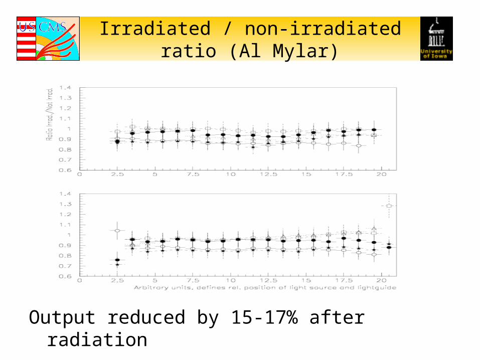
Irradiated / non-irradiated ratio (Al Mylar)
Output reduced by 15-17% after radiation
CONCLUSION
• Better results with HEM
PMT X-Y uniformity improves and goes to a plateau when HEM reflecting material is used
• No significant difference between tapered and straight light guides
• No radiation damage was observed for HEM
Output decrease in irradiated Al Mylar