Embed Size (px)
Citation preview
..,.J~~,_, ~.
~,
LEHIGH UNIVERSITY
DEPARTMENT OF CIVIL ENGINEERING . .FRITZ ENGINEERING LABORATORY
BETHLEHEM. PA.
September 9, 1949
File No. 205C
To: Members, Lehigh Project SubcommitteeStruc tura 1 Steel Commi t.teeWelding Research Cnuncil
REVISED PROPOSAL FOR CONNECTION[ rrESTS
Gentlemen: .
PHONEBETHLEHEM 7·507'
FRITZ E. i... OFFICE EXT. 256
HYDRAULICS LAB. EXT. 279
Themlnutes of ,the June second, 1949, meeting ofthe Lehigh Subcommitte~ call for a proposal cn connectiontests. It is the purpose 6f this letter to forward to youour recommendations. This. revision is intended to supplement tb6)previous proposals and discussions that have beenissued(l _
PUHPOSE
As a part of the study to determine the besic behavior of welded joints in the elastic and plastic range,it is the primary purpose of these IImodel B tests to studythe influence of certain variables yvj. tlJin several connectiontypes. An example is the influence of radius of curvatureand thickness of'curved flanges •
. -PROGRAM OF TESTS
A total of 14 tests are proposed as shown in Table 10The sketch of connection types originally included in ProgressReport IlA lf is presented in modified form as Fig. 1 for 1nformation. Figs. 3-9, containing detail drawings of thevarious connection types, are referred to in Table I.
"
Although not strictly in accordance withstated above, tests, I C" and ilN il are suggested. forson with the other tests of ilbracketed li corners.taken from actual construction examples.
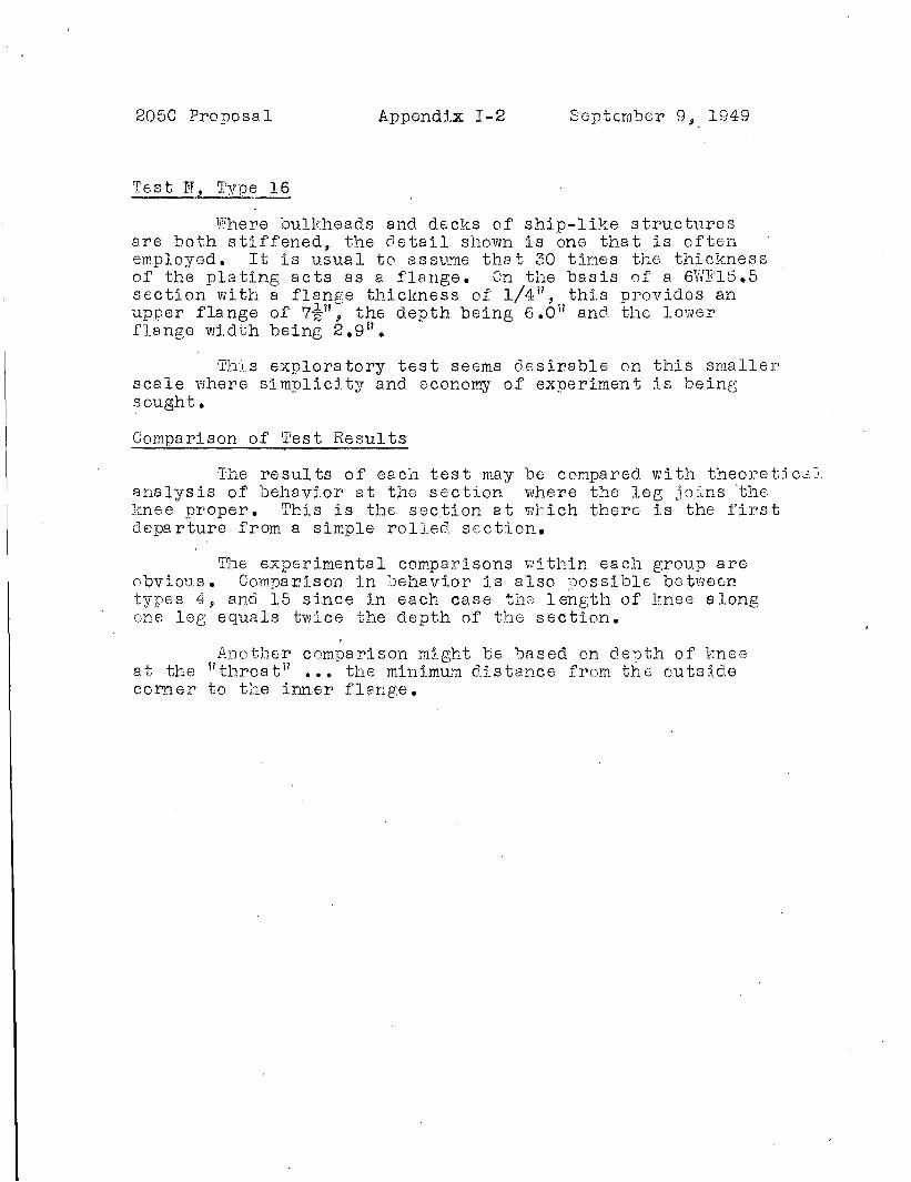
SELECTION OF SECTION
the purposecompariBoth are
Use of a 6 11 section is recorm~1ended. 1"106els usj.ngthis section can be handled without a cran6, which will
-" - . ~ - - - - - - - - ;. - - - - - - - - - - - - - -( l) Progress Report A, Nov. 26:, 1948, Appendix B.
~ - " Progress Report E JUn. 1, 1949. .., .,- 'Proposal to Office of Naval Research, May 7 1948,p.l of By;,..',',~t." Progress Roport P July 19, 1949, 9., p.
2050 Revised Proposal - 2 - September 9, 1949
facilitate the experimental program.
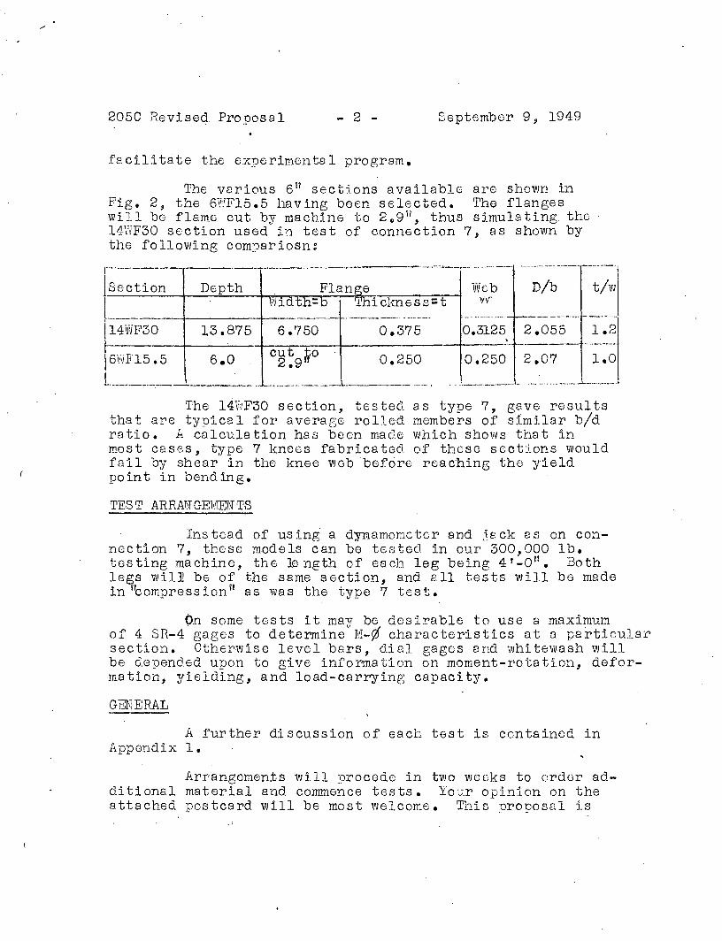
The various 6 11 secti.ons available are shown inFig. 2, the 6~F15.5 having been selected. The flangeswill be flame cut by machinE; to 2 .. 9 11 , thus simulating the14WF30 section used in test of connE;ction 7, as shown bythe following comDariosn:r.-------r-----,.----·.. ------·----·-="~=·-·--·· ..... -.-----'
ISection Depth Flange Webt-----l---........---l.....,Vn:'ri\V."..i":'rd-r"t..-:h:=,...b-t~r'*'h-l~·~ c"""l:--{n e s s=t V'f"
nib tlw
2.055 1.2
0.250
14VvF30---.---.---t--,..--.----f--------.- .-'-- -_....._-..
13.875 6.750 0.375 0.3125f------l-----'----1f----,...--:----l---------t---'
6.0 c~~9~o 0.250• __ ._. ~._. . __..... _.__...... ,_.~._- __---........... ._.._._, . __ ',.__._.__• .• "'•.•..•. _. __ ..... _.t.
The 14~F30 section, tE;sted as typE; 7, gave resultsthat are typical for average rolled members of similar bidratio. A calculation has been made which shows that inmost cas6s, type 7 knees fabricated of these sections wouldfail by shear in the knee web 'before reaching the yieldpoint in bending.
TEST ARRANGEMENTS
Instead of using a dynamometer and jack as on connection 7, these models can be testee in our 300,000 lb.testing machine, the 16 ngth of each leg being 4 '_0". Bothlegs will bE; of the same section, and all tests will be madein "compression" as was the type 7 test.
On some tests it mav be desirable to use a maximumof 4 SR-4gag8s to determine
U M-0 characteristics at a particularsection. Otherwise level bars, dial gages and whitewash willbe depended upon to give information on moment-rotatj.on, deformation, yielding, and load-carrying capacity.
GENERAL
A further discussion of each test is contained inAppendix 1.
ArrangemE;nts will procede in two weoks to order additional material and commence tests. Your opinion on theattached postcard will be most welcome. This Droposal is
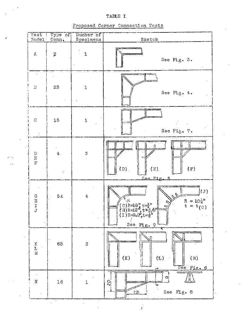
TABLE I
Proposed Corner Connection Tests
I Test ! Type of' NU.m.ber of1--li9de1 : Conn. Specimens Sketch ---,
I
fI r- ::1I ,
A ! ~ 1 .~
I JI See Pig. 3.
III ---------
I !
~! Ii
I
! I r]J/
2B 1I
See Fig. 4.
I I,i
~I Il_ I 1II !
-J \I \I
I
I C 15 1 ~....
iII I See Fig. 7.I I c--lI
t--I
~ II;J=:I [DC M
~I (I n tiI·
I D I 4 3 ';r //~
yI E -'~'lr
C"" r.. :'~I.::- r
I F II Jl (D). I (E) I (F)I
I I '--- I---
I c:.P.A Ti'i C1' Rf ~
I
~ f ~:JU)iI G 5A 4
H r"~'~8 I ~~ = 10i'"I '= 'I (G)R~18" t-~" Kr t ~. t( .)J
I--- 01) R=12 ", t::3;8"' G
( I )R~.O~,t=!" LJ . ..,. ----- See F:i,g. 9 .
I,
r~.... ifFJ~ \I l~ )I: ~nK 8B 3 \
Ii IL I
Ui
Iv!,.
I(K) I I (L) ( M)
'--- '-See' Fig.r'> 6
I -+ 11 =&
,
I II I
i 0:N 16 1 O' ---.t: INI ~II /;/ I
.L -;;;.--- I See Fig. 8,.. 'Z.D .1i ----
205C Proposal Septembe~ 9, 1949
APPENDIX I
DISCUSSION OF TESTS
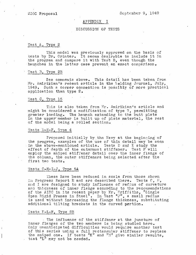
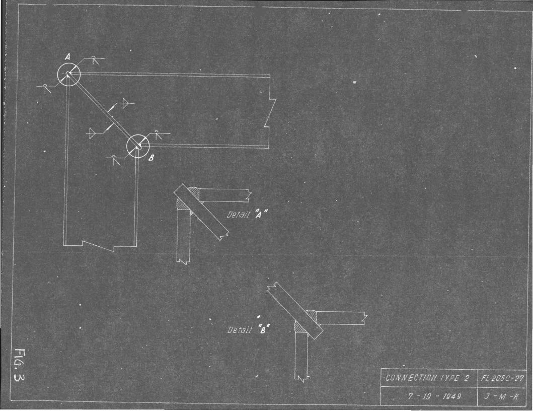
Test A, Type 2
This model was previously approved on the basis oftests by Dr. Grinter. It seems de~irable to include it inthe program and compare it with Test B, even though the
.haunches in the la tter oase prevent an exact conr9arison,
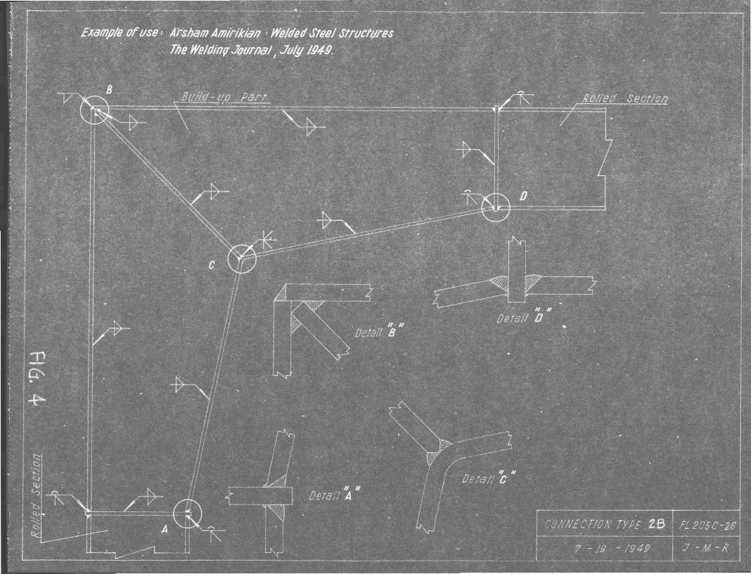
Tes t B, r:I'ype 2B
See comments above. This detail has .been taken fromr1r. Amirikian'srecent article in the v\elding Journal, JUly,1949. Such a corner conne,ction is possibly of more practicalapplication than type 2.
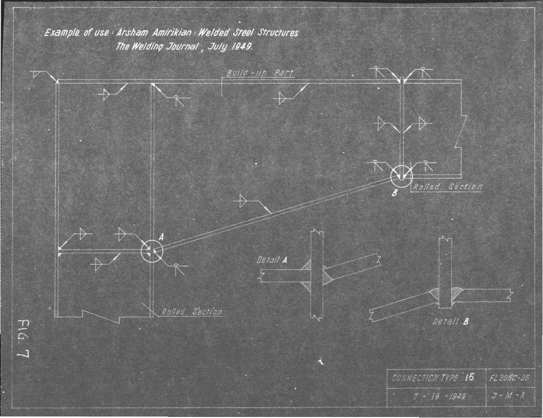
r.l'es t C, Type 15
This is also taken from Mr. Amirikian's article andmight be considered a modifica tion of type 7, permi ttinggreater loading. The haunch extending to the butt platein the upper'member is built up of plate material, the restof the model being a rolled section.
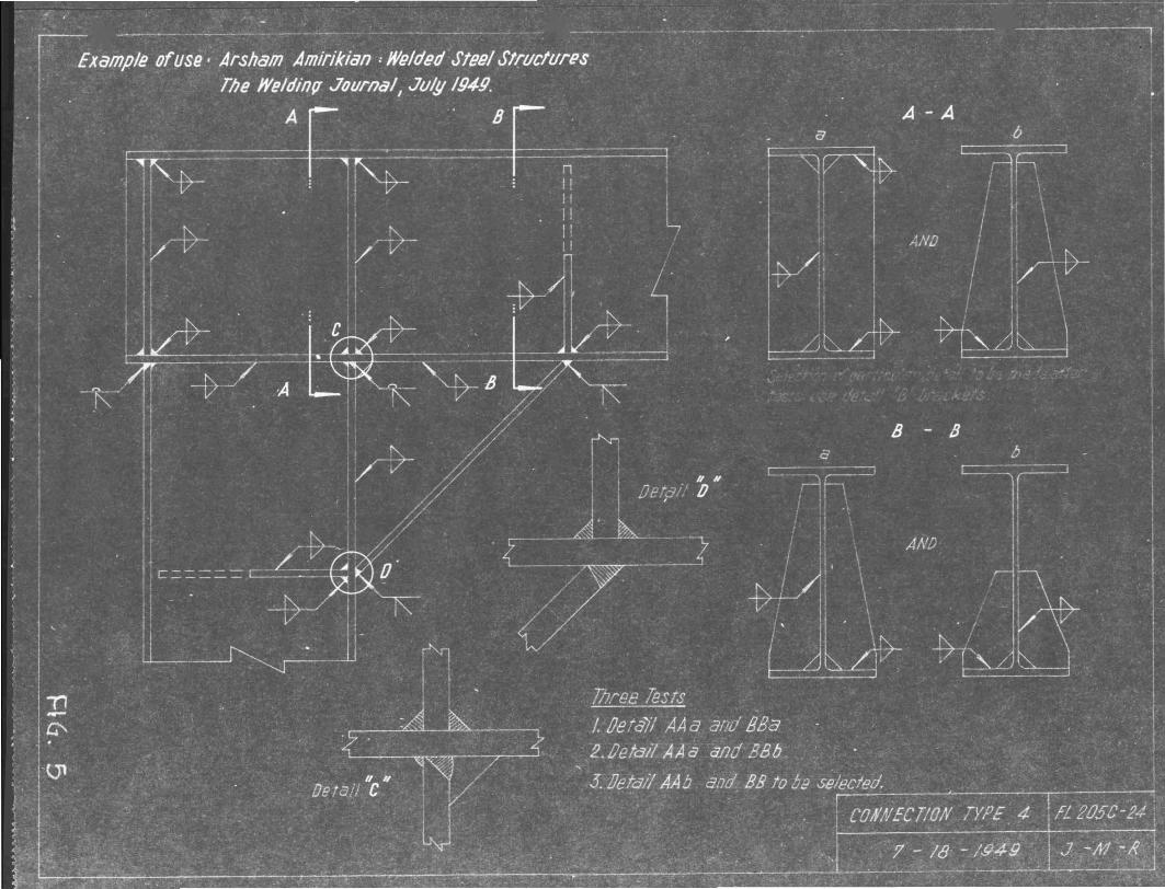
Tests D-E-r, Type 4
Proposed initially by the Navy at the beginning ofthe program, examples of the use of this detail may be seenin the above-mentioned article. Tests D and E study theeffect of depth of the outermost stiffener. Test F willemWloy the sniped stiffener detail over the inner flange ofthe column, the outer stiffeners being selected after thefirst two tests.
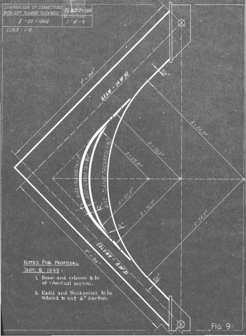
Tests G-H-I-J, Type 5A
These have been reduced in scale from those shownill Progress Report E and are des cribed there. Tea ts G, IT,aDd I are designed to study influence of radius of curvatureand thickness of inner flange according to the recommendations9f the AISC in j, ts recent paper by Mr. Griffi ths, "s ingleSpan Rigid Frames in Stee 1 II • In Ires t "3", a sma +1 radiusis used without increasing the flange thickness, substitritingaddi t ion a 1 ti 1 t ing bra eke ts in the curved par t ion.
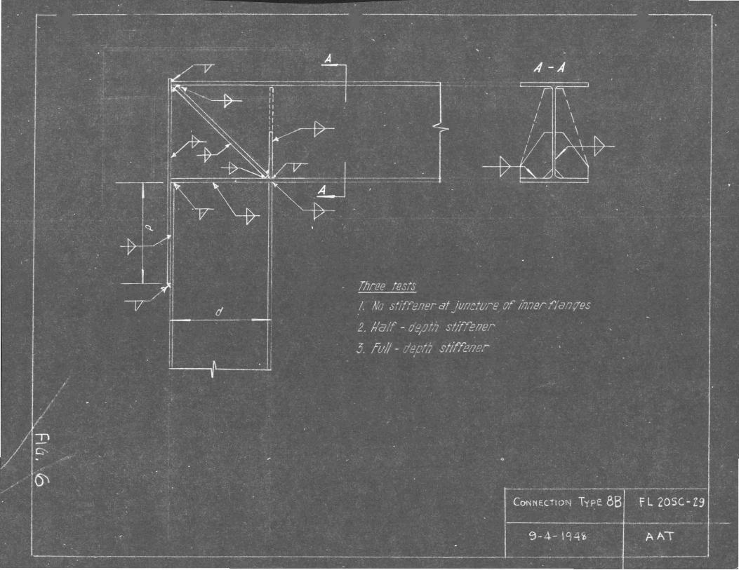
rI'es ts Y -L-M, Type 8B
. The influence of the stiffener at the juncture ofinner flanges of the two members is being studied here.Only unanticipated difficulties would require another testof thi s series usi ng a full re c tangula r stiffener to repla cethe sniped one. If tes ts "K II and il~.1ir give similar re suI ts,test "L" may not be needed.
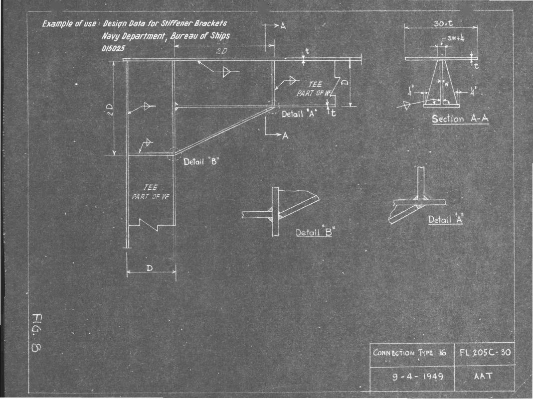
205C Proposal Appendix 1-2 September 9, 1949
Where bulkheads and decks of ship-like structuresare both stiffened, the detail shown is one that is oftenemployed. It is usual to assume that 30 tim.es the thicknessof the plating acts as a flenge. On the basis of a 6WF15.5section with a flange tb.iclmess of 1/4 11
, thj,s provides an·upper flange of 7i ll
, the depth being 6.0 il ancl. the lO'i,Jerflange width being 2.9 11 •
This exploratory test seems desirable on this smallerscale where simplicity and oconomy of experiment is beingsought.
Com.parison of Test Results
Tl1.e results of each test may be compared with theoretic,?='.8n8 lys is of' behavior a t the sec tion '!ivhere the leg joins 'thE.knee proper. This is the sec~ion at which there is the firstdeparture from a simple rolJ.ed section.
The experimental comparisons within each group areobvious. Comparj.son in behavior is also possible betl"Jeentypes 4, and 15 since in each case th8 length of knee alongone leg equals twice the depth of the section.
,Another comparison might be based on depth of knee
at the iltbroat l1••• the minimum distance from tho outside
corner to the inner flenge.
/lifTid frame Corner Connections. fl20§['-3/
J-M-R


![MŁOTKI - NARZĘ 10 - CBT205C - Młotki dla mechanika typu DIN z trzonkiem grafitowym L [mm] L1 [mm] L2 [mm] [kg] 205C.20 280 96 19 0,250 205C.30 300 106 23 0,380 205C.50 320 122](https://img.dokumen.tips/doc/110x75/60be29d9e459a1141d4a1654/motki-narz-10-cbt-205c-motki-dla-mechanika-typu-din-z-trzonkiem-graitowym.jpg)