Embed Size (px)
Citation preview
© Strojniški vestnik (43) št. 1-2, str. 5-18, 1997 Tiskano v Sloveniji. Vse pravice pridržane.
SV: 0039-2480(97)1-R1
Izkoriščanje eksergije pri ekspanziji zemeljskega plina The Use of Exergy in the Expansion of Natural Gas
MATIJA TUMA - MIHA SEKAVČNIK
Uporaba ekspanzijskih strojev za pridobivanje električne energije p ri znižanju tlaka v plinovodnih omrežjih se je v praksi izkazala za tehnično izvedljivo in ekonomsko upravičeno. Da bi dobili boljše podatke o termodinamičnih procesih z zemeljskim plinom, so bili izdelani diagrami h-s za različne sestave zemeljskega plina in primerjani termodinamični procesi na različnih tlačnih ravneh. Podrobneje je bil analiziran primer uporabe ekspanzijskega stroja v ljubljanskem plinovodnem omrežju s tehničnega in gospodarnega vidika.Ključne besede: stroji ekspanzijski, eksergija, procesi termodinamični, plini zemeljski
The use o f expansion machines fo r the production o f electrical power in order to reduce gas pressure in gas supply networks has proved in practice to be both technically feasible and econo- nomically justifiable. In order to obtain better data on thermodynamic processes involving natural gas, h-s diagrams were made fo r different compositions o f natural gas and thermodynamic processes were compared at different pressure levels. An example o f the use o f an expansion machine in the Ljubljana gas supply network was analysed in greater detail from the technical and economic standpoints.Keywords: expansion machines, exergy, thermodynamic processes, natural gas
0 UVOD
Zemeljski plin se transportira do končnih porabnikov po različnih plinovodnih omrežjih pri temperaturi okolice. Plinovodna omrežja, kijih poleg za transport in razdeljevanje uporabljamo tudi za sezonsko shranjevanje zemeljskega plina, obratujejo na različnih tlačnih nivojih. V grobem jih lahko razvrstimo v naslednje skupine [5]:
- sezonski hranilniki: do 100 bar,- glavni transportni plinovodi: do 80 bar,- regionalni plinovodi: 30 do 50 bar,- mestni plinovodi: 3 do 12 bar,- plinovod za končno oskrbo: 1,2 bar.Ob sezonskih hranilnikih plina in glavnih
transportnih plinovodih so zgrajene kompresorske postaje, ki skrbijo za transport plina in vzdrževanje tlaka (pokrivanje tlačnih izgub). Tlak v plinovodnih sistemih ni stalen, saj prihaja zaradi dinamike porabe plina do znatnih tlačnih nihanj.
Med posameznimi omrežji so reducime postaje, kjer se tlak zniža na nižji tlačni nivo. Znižanje tlaka v reducirnih postajah poteka z dušenjem. Pri tem procesu, ki je v prvem približku izentalpen in brez izmenjave toplote z okolico, ne pridobimo nobenega dela; eksergija se preobrazi v tehnično neuporabno anergijo.
Padec tlaka z dušenjem lahko nadomestimo z ekspanzijskim strojem, pri čemer pridobimo znaten del mehanskega dela, ki smo ga v sistem vložili v kompresorskih postajah. Taka postrojenja uspešno obratujejo v Evropi že od leta 1973 [7], [10], [14] in [17].
0 INTRODUCTION
Natural gas is transported to final consumers via various gas supply networks at ambient temperature. Gas supply networks, which serve for the transport and distribution of natural gas, but also for its seasonal storage, operate at different pressure leve ls . T hey can ro u g h ly be c la s s if ie d in to the fo 1 lowing groups [5]:
- seasonal reservoirs: up to 100 bar,- inter-regional gas pipelines: up to 80 bar,- regional gas pipelines: 30 to 50 bar,- city gas pipelines: 3 to 12 bar,- gas pipeline to final consumers: 1.2 barCompressor stations are installed at seasonal
reservoirs and inter-regional gas pipelines and they ensure the transport o f gas and maintenance o f pressure (by compensating for pressure drops). Pressure in gas supply systems is not constant, since considerable variations in pressure occur due to the dynamics o f gas consumption.
Reducing stations, at which pressure is reduced to a lower pressure level, are installed between individual networks. The reduction o f pressure in reduction stations is achieved through damping. In this process, which is isenthalpic in its first approximation, without any exchange of heat with the environment, no work is obtained; the exergy is transformed into technically useless anergy.
The reduction in pressure achieved by damping can be reversed with an expansion machine, whereby a considerable part of the mechanical work which was added to the system at compressor stations is recovered. Such plants have been in operation successfully since 1973 [7], [10], [14], and [17].
1 DIAGRAM h-s ZA RAZLIČNESESTAVE ZEMELJSKEGA PLINA
Zemeljski plin ima različne sestave, ki se sčasoma spreminjajo. V grobem jih lahko razvrstimo v tri velike skupine: severnomorski zemeljski plin, ruski zemeljski plin in holandski zemeljski plin [18].
Pretežno je zemeljski plin sestavljen iz metana (CH4), v manjših deležih pa so še nekateri drugi ogljikovodikimpr. etan (C2H6) in propan (C3Hg) ter drugi plini: npr. dušik (N2) in ogljikov dioksid (C 02). V preglednici je p rikazana značilna sestava zemeljskega plina. Omenjene navedbe veljajo za že očiščeni zemeljski plin. Pred transportom v plinovodno omrežje je treba namreč nekatere spojine (predvsem žveplovodik in vodno paro), ki so pri naravnih razmerah navzoče v zemeljskem plinu, odstraniti oz.
1 DIAGRAMS h-s FOR DIFFERENT COMPOSITIONS OF NATURAL GAS
Natural gas differ in its composition and this in turn varies with time. Roughly its can be classified into three large groups: North Sea natural gas H, Russian natural gas H and Dutch natural gas L [18].
Natural gas consists predominantly o f methane (CH4); certain other hydrocarbons are present in smaller amounts - e.g. ethane (C2H,) and propane (C3H8), and non-hydrocarbons - e.g. nitrogen (N2) and carbon dioxide (C 0 2). Table 1 presents the characteristic composition o f natural gas.The above applies to purified natural gas. Prior to the transport of gas into the gas supply network, certain compounds (above all hydrogen sulphide and water vapour) which are present in natural gas under normal conditions,
zmanjšati. are removed or reduced.
Pregednica. 1 : Značilna sestava zemeljskega plinaTable 1: Characteristic composition o f natural gas
Komponenta zemeljskega plina Component of natural gas
metan c h 4 80-9 methane CH4 80-9etan C2H6 0,5-10 ethane C2H6 0,5-10propan c 3h 8 0,2-5 propane c 3h 8 0,2-5butan, višji ogljikovodiki c 4h ,0 0,5-1 butane, higher hydrocarbons c 4h 10 0,5-1dušik N 2 0,5-12 nitrogen N2 0,5-12ogljikov dioksid c o 2 0,1-2 carbon dioxide c o 2 0,1-2
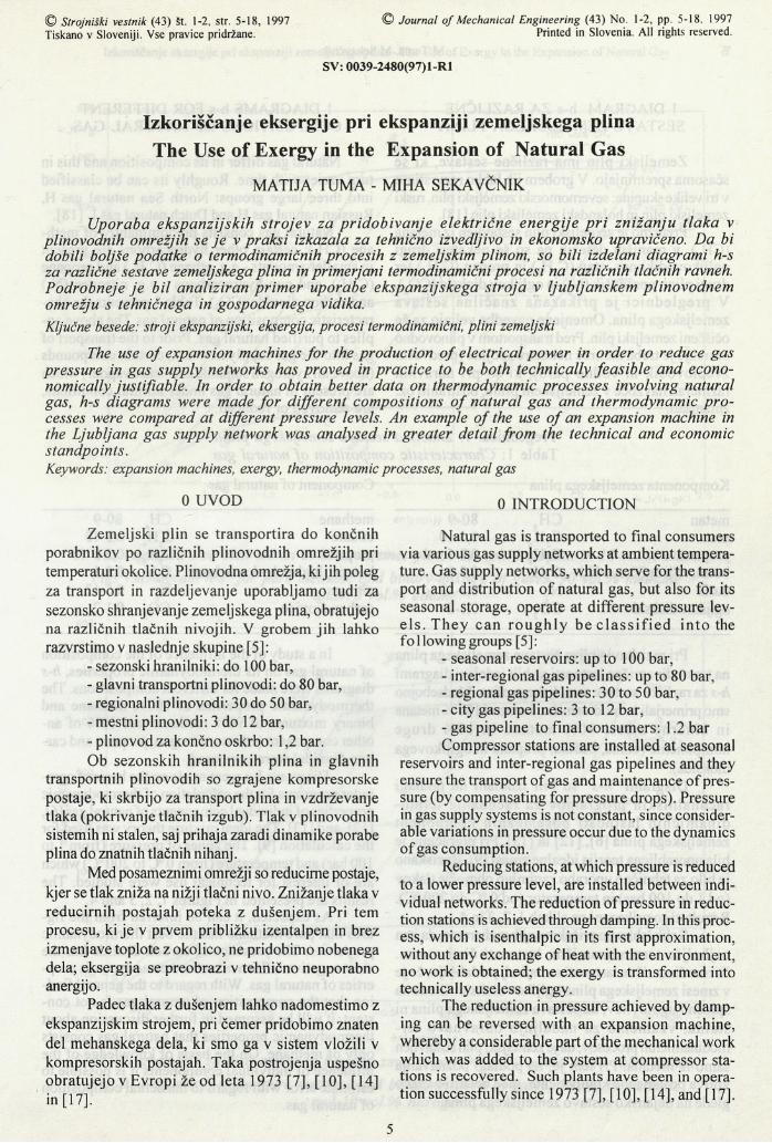
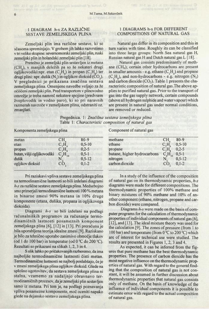
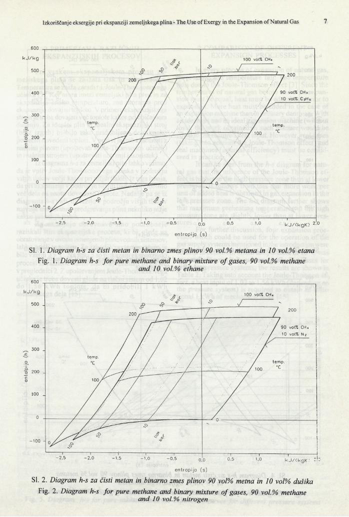
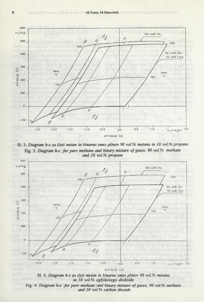
Pri raziskavi vpliva sestave zemeljskega plina na termodinamične lastnosti so bili izdelani diagrami h-s za različne sestave zemeljskega plina. Medsebojno smo primeijali termodinamične lastnosti 100 % metana in binarne zm esi 90% m etana in 10% druge komponente (etana, dušika, propana in ogljikovega dioksida).
Diagrami h-s so bili izdelani na podlagi računalniških program ov za računanje term odinam ičnih lastnosti posam eznih kom ponent zemeljskega plina [6], [12] in [13]. Pri preračunu je bila uporabljena teorija idealne zmesi [9]. Raziskano je bilo za tehnično uporabo zanimivo območje tlakov (od 1 do 100 bar) in temperatur (od 0 °C do 200 °C). Rezultati so prikazani na slikah 1,2, 3 in 4.
S slik lahko po pričakovanjih razberemo, da ima najboljše termodinamične lastnosti čisti metan. Termodinamične lastnosti se najbolj poslabšajo, če je v zmesi zemeljskega plina ogljikov dioksid. Glede na splošno ugotovitev, da sestava zemeljskega plina ni stalna, vzamemo za nadaljnjo obravnavo termodinamičnih procesov, daje zemeljski plin sestavljen samo iz metana. Pri tem je, na podlagi poznavanja vpliva posamezne komponente, moč oceniti napako glede na dejansko sestavo zemeljskega plina.
In a study of the influence of the composition of natural gas on its thermodynamic properties, h-s diagrams were made for different compositions. The thermodynamic properties of 100% methane and binary mixtures of 90% methane and 10% of another component (ethane, nitrogen, propane and carbon dioxide) were compared.
Diagrams h-s were made on the basis of computer programs for the calculation of thermodynamic properties of individual components of natural gas [6], [12], and [13]. The ideal mixture theory was used for the calculation [9]. The zones o f pressure (from 1 to 100 bar) and temperature (from 0 °C to 200 °C) which are of interest for technical use were studied. The results are presented in Figures 1, 2, 3 and 4.
As expected, it can be inferred from the figures that pure methane has the best thermodynamic properties. The presence of carbon dioxide has the most negative influence on the thermodynamic properties of natural gas. With regard to the general finding that the composition o f natural gas is not constant, it will be assumed in further discussion about thermodynamic properties that natural gas consists only of methane. On the basis of knowledge of the influence of individual components it is possible to estimate error with regard to the actual composition of natural gas.
en
tolp
ija
(h)
en
talp
ija
(h)
Sl. 1. Diagram h-s za čisti metan in binarno zmes plinov 90 vol.% metana in 10 vol.% etanaFig. 1. Diagram h-s fo r pure methane and binary mixture o f gases, 90 vol.% methane
and 10 vol.% ethane
SI. 2. Diagram h-s za čisti metan in binarno zmes plinov 90 vol% metna in 10 vol% dušikaFig. 2. Diagram h-s for pure methane and binary mixture o f gases, 90 vol.% methane
and 10 vol.% nitrogen
Sl. 3. Diagram h-s za čisti metan in binarno zmes plinov 90 vol.% metana in 10 vol.% propanaFig. 3. Diagram h-s fo r pure methane and binary mixture o f gases, 90 vol.% methane
and 10 vol.% propane
SI. 4. Diagram h-s za čisti metan in binarno zmes plinov 90 vol.% metana in 10 vol.%) ogljikovega dioksida
Fig. 4. Diagram h-s for pure methane and binary mixture o f gases, 90 vol.% methaneand 10 vol.%) carbon dioxide
2 PRIMERJAVA RAZLIČNIH EKSPANZIJSKIH PROCESOV
Pri vsakem ekspanzijskem procesu zemeljskega plina se znižata tlak in temperatura. Temperatura se zniža zaradi t.i. Joule-Thomsonovega učinka [3], Ker mora imeti zemeljski plin pred in za ekspanzijo enako temperaturo, mu moramo pred ekspanzijo dovajati toploto. V primeru ekspanzijskega stroja je treba dovajati več toplote kakor pri običajnem dušenju. Za idealni plin in idealni ekspanzijski stroj (brez izgub) bi bilo tako pridobljeno delo enako potrebni dovedeni toploti. V praksi je treba računati z realnim plinom (upoštevati Joule-Thomsonov učinek) in realnim strojem (upoštevati notranji izkoristek).
Iz diagrama h-s za zemeljski plin lahko vidimo, daje vpliv Joule-Thomsonovega učinka v področju višjih tlakov večji kakorpri nižjih tlakih. Iz tega izhaja, da pri ekspanziji v področju nižjih tlakov pridobimo več dela na enoto dovedene toplote. Nadalje pa se iz diagrama h-s vidi, da ležijo v področju višjih tlakov najvišje temperature predgrevanja plina nekoliko nižje kakor pri nižjih tlakih.
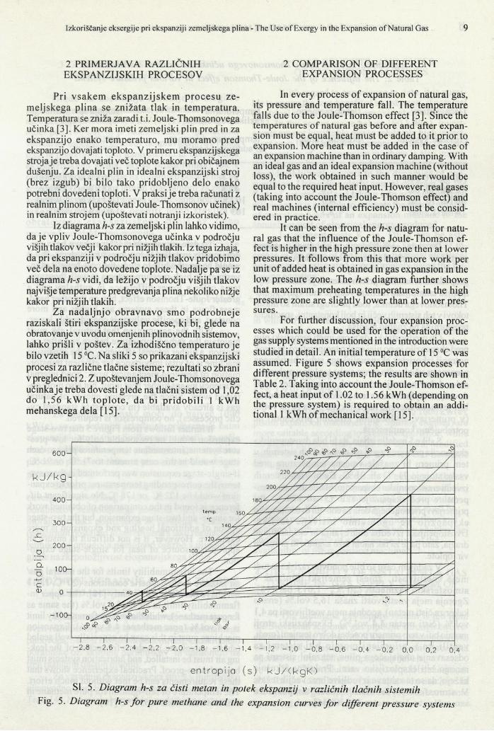
Za nadaljnjo obravnavo smo podrobneje raziskali štiri ekspanzijske procese, ki bi, glede na obratovanje v uvodu omenjenih plinovodnih sistemov, lahko prišli v poštev. Za izhodiščno temperaturo je bilo vzetih 15 °C. Na sliki 5 so prikazani ekspanzijski procesi za različne tlačne sisteme; rezultati so zbrani v preglednici 2. Z upoštevanjem Joule-Thomsonovega učinka je treba dovesti glede na tlačni sistem od 1,02 do 1,56 kW h top lo te , da bi p ridobili 1 kWh mehanskega dela [15],
2 COMPARISON OF DIFFERENT EXPANSION PROCESSES
In every process o f expansion o f natural gas, its pressure and temperature fall. The temperature falls due to the Joule-Thomson effect [3]. Since the temperatures o f natural gas before and after expansion must be equal, heat must be added to it prior to expansion. More heat must be added in the case of an expansion machine than in ordinary damping. With an ideal gas and an ideal expansion machine (without loss), the work obtained in such manner would be equal to the required heat input. However, real gases (taking into account the Joule-Thomson effect) and real machines (internal efficiency) must be considered in practice.
It can be seen from the h-s diagram for natural gas that the influence of the Joule-Thomson effect is higher in the high pressure zone then at lower pressures. It follows from this that more work per unit o f added heat is obtained in gas expansion in the low pressure zone. The h-s diagram further shows that maximum preheating temperatures in the high pressure zone are slightly lower than at lower pressures.
For further discussion, four expansion processes which could be used for the operation of the gas supply systems mentioned in the introduction were studied in detail. An initial temperature of 15 °C was assumed. Figure 5 shows expansion processes for different pressure systems; the results are shown in Table 2. Taking into account the Joule-Thomson effect, a heat input o f 1.02 to 1.56 kWh (depending on the pressure system) is required to obtain an additional 1 kWh o f mechanical work [15],
entropi ja (s) k J A k g K )
SI. 5. Diagram h-s za čisti metan in potek ekspanzij v različnih tlačnih sistemih Fig. 5. Diagram h-s fo r pure methane and the expansion curves fo r different pressure systems
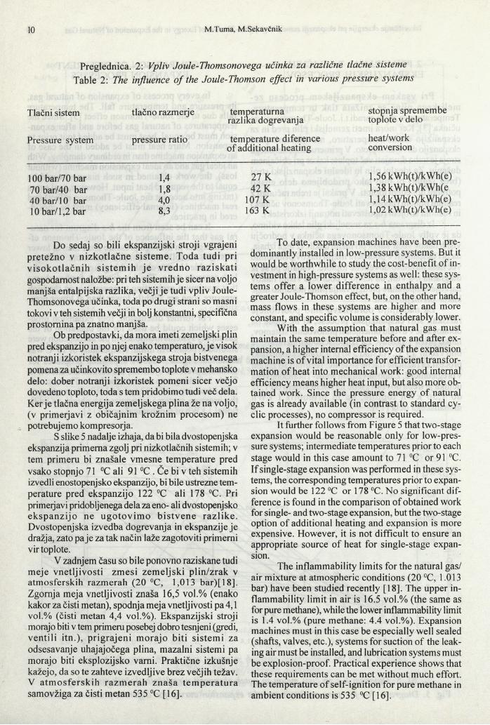
Preglednica. 2: Vpliv Joule-Thomsonovega učinka za različne tlačne sisteme Table 2: The influence o f the Joule-Thomson effect in various pressure systems
Tlačni sistem tlačno razmerje temperaturna razlika dogrevanja
stopnja spremembe toplote v delo
Pressure system pressure ratio temperature diference of additional heating
heat/workconversion
100 bar/70 bar 1,4 27 K 1,56 kWh(t)/kWh(e)70 bar/40 bar 1,8 42 K 1,38 kWh(t)/kWh(e40 bar/10 bar 4,0 107 K 1,14 k Wh(t)/k Wh(e)10 bar/1,2 bar 8,3 163 K 1,02 kWh(t)/kWh(e)
Do sedaj so bili ekspanzijski stroji vgrajeni pretežno v nizkotlačne sisteme. Toda tudi pri v isoko tlačn ih sistem ih je vredno raz iskati gospodarnost naložbe: pri teh sistemih je sicer na voljo manjša entalpijska razlika, večji je tudi vpliv Joule- Thomsonovega učinka, toda po drugi strani so masni tokovi v teh sistemih večji in bolj konstantni, specifična prostornina pa znatno manjša.
Ob predpostavki, da mora imeti zemeljski plin pred ekspanzijo in po njej enako temperaturo, je visok notranji izkoristek ekspanzijskega stroja bistvenega pomena za učinkovito spremembo toplote v mehansko delo: dober notranji izkoristek pomeni sicer večjo dovedeno toploto, toda s tem pridobimo tudi več dela. Ker je tlačna energija zemeljskega plina že na voljo, (v primerjavi z običajnim krožnim procesom) ne potrebujemo kompresorja.
S slike 5 nadalje izhaja, da bi bila dvostopenjska ekspanzija primerna zgolj pri nizkotlačnih sistemih; v tem primeru bi znašale vmesne temperature pred vsako stopnjo 71 °C ali 91 °C . Če bi v teh sistemih izvedli enostopenjsko ekspanzijo, bi bile ustrezne temperature pred ekspanzijo 122 °C ali 178 °C. Pri primerjavi pridobljenega dela za eno- ali dvostopenjsko ekspanzijo ne ugotovim o b istvene razlike. Dvostopenjska izvedba dogrevanja in ekspanzije je dražja, zato pa je za tak način laže zagotoviti primerni vir toplote.
V zadnjem času so bile ponovno raziskane tudi meje vnetljivosti zmesi zem eljski plin/zrak v atmosferskih razmerah (20 °C, 1,013 bar)[18]. Zgornja meja vnetljivosti znaša 16,5 vol.% (enako kakor za čisti metan), spodnja meja vnetljivosti pa 4,1 vol.% (čisti metan 4,4 vol.%). Ekspanzijski stroji morajo biti v tem primeru posebej dobro tesnjeni (gredi, ventili itn.), prigrajeni m orajo biti sistem i za odsesavanje uhajajočega plina, mazalni sistemi pa morajo biti eksplozijsko varni. Praktične izkušnje kažejo, da so te zahteve izvedljive brez večjih težav. V atm osfersk ih razm erah znaša tem pera tu ra samovžiga za čisti metan 535 °C [16].
To date, expansion machines have been predominantly installed in low-pressure systems. But it would be worthwhile to study the cost-benefit of investment in high-pressure systems as well: these systems offer a lower difference in enthalpy and a greater Joule-Thomson effect, but, on the other hand, mass flows in these systems are higher and more constant, and specific volume is considerably lower.
With the assumption that natural gas must maintain the same temperature before and after expansion, a higher internal efficiency of the expansion machine is of vital importance for efficient transformation of heat into mechanical work: good internal efficiency means higher heat input, but also more obtained work. Since the pressure energy of natural gas is already available (in contrast to standard cyclic processes), no compressor is required.
It further follows from Figure 5 that two-stage expansion would be reasonable only for low-pressure systems; intermediate temperatures prior to each stage would in this case amount to 71 °C or 91 °C. If single-stage expansion was performed in these systems, the corresponding temperatures prior to expansion would be 122 °C or 178 °C. No significant difference is found in the comparison o f obtained work for single- and two-stage expansion, but the two-stage option of additional heating and expansion is more expensive. However, it is not difficult to ensure an appropriate source of heat for single-stage expansion.
The inflammability limits for the natural gas/ air mixture at atmospheric conditions (20 °C, 1.013 bar) have been studied recently [18], The upper inflammability limit in air is 16.5 vol.% (the same as for pure methane), while the lower inflammability limit is 1.4 vol.% (pure methane: 4.4 vol.%). Expansion machines must in this case be especially well sealed (shafts, valves, etc.), systems for suction of the leaking air must be installed, and lubrication systems must be explosion-proof. Practical experience shows that these requirements can be met without much effort. The temperature o f self-ignition for pure methane in ambient conditions is 535 °C [16].
3 GOSPODARNOST IN VRSTE EKSPANZIJSKIH STROJEV
Glede na dosedanje izkušnje je m ogoče zagotoviti gospodarnost naložbe, če imenska električna moč presega približno 400 kW (e) [11]. V področju moči pod 100 kW(e) je naložba zaradi razmeroma velikih investicijskih stroškov neupravičena [8], Poleg tega je pomembno tudi letno število ur obratovanja ekspanzijskega stroja, saj se prostorninski tok v reducirnih postajah glede na dinamiko porabe močno spreminja. Z urejenim letnim diagramom za pretok zemeljskega plina in hkratnega upoštevanja notranjega izkoristka je m ogoče oceniti letno število ur ob ratovan ja ek spanz ijskega s tro ja oz. letno proizvedeno električno energijo.
Iz diagrama v [8] lahko ocenimo investicijske stroške KA v DEM.Trend naraščanja cene postrojenja v odvisnosti od imenske električne moči lahko približno ocenimo z enačbo:
kjer PE pomeni imensko električno moč.Po tej enačbi se zm anjšujejo specifični
investicijski stroški &Az večanjem imenske električne moči PE v kW, na primer:
PE = 500 kW P = 3 000 kWE
Za manjše imenske moči, do največ 1000 kW(e), so po sedanjih izkušnjah primernejši batni ekspanzijski stroji (npr. Spillingovi motorji), za večje moči, od 1000 kW naprej, pa prirejene parne turbine, procesne plinske turbine in povsem zaprti turbinski generatorji [11].
Seveda je treba poudariti, d a je izkoriščanje eksergije zemeljskega plina ob nemoteni oskrbi porabnikov sekundarnega pomena. To pomeni, da morajo biti taka postrojenja že vgrajena k sedanjim reducimim postajam in opremljena s tako regulacijsko tehniko, ki omogoča nemoteno oskrbo s plinom, ne glede na razpoložljivost ekspanzijskega stroja.
4 MOŽNOST VGRADNJE PLINSKE TURBINE V LJUBLJANSKI PLINOVODNI SISTEM
Ljubljansko plinovodno omrežje se napaja prek dveh reducirnih postaj iz slovenskega regionalnega plinovoda. Sestoji iz sistema podomrežij, ki oskrbujejo porabnike oz. skupine porabnikov in obratujejo na treh različnih tlačnih nivojih.
Za vgradnjo ekspanzijskega stroja v ljubljansko plinovodno omrežjeje najprimernejša reducima postaja Trata [4],Nekateri obratovalni podatki te postaje so:
3 COST-BENEFITS AND TYPES OF EXPANSION MACHINES
With regard to experience to date, it is possible to ensure the cost-benefit of investments, if nominal electrical power exceeds approximately 400 kW(e) [11]. In the power range below 100 kW(e), investments are not justifiable due to relatively high investment costs [8], In addition, the annual number of hours of operation of an expansion machine is also important, since volume flow in reduction stations changes considerably with respect to the dynamics o f consumption. Using an orderly annual diagram for the flow of natural gas and taking into account internal efficiency, it is possible to estimate the annual number of operating hours o f an expansion machine or the annual amount of electrical energy produced.
Investment costs KA in DEM can be estimated on the basis of diagrdm [8]. The trend of increase in the price o f the plant vs. nominal electrical power can be estimated approximately using the following equation:
( 1),
in which P£ is the nominal electrical power.According to this equation, specific investment
costs k . decrease with an increase in nominal elec-Atrical power PE in kW, for example:
kk = 3 600 DEM/kW k = 1 930 DEM/kWA
For smaller nominal powers, up to 1000 kW(e), piston expansion machines (e.g. Spilling engines) are more suitable according to present experience, while for higher powers, from 1000 kW upward, modified steam turbines, process gas turbines and hermetic turboaggregates [11] are better.
Naturally, it is necessary to emphasise that for an undisturbed supply o f consumers the exploitation of the exergy o f natural gas is o f secondary importance. This means that such plants must be installed parallel to existing reduction stations and equipped with control equipment which enables the undisturbed supply of gas, irrespective o f the availability of the expansion machine.
4 THE POSSIBILITY OF INSTALLING A GAS TURBINE IN GAS SUPPLY SYSTEM OF
LJUBLJANA
The Ljubljana gas supply system is fed from the Slovenian regional gas pipeline through two reduction stations. It consists of a system of subnetworks which supply consumers or groups o f consumers and operate at three different pressure levels.
The Trata reduction station would be most suitable for the installation of an expansion machine in the Ljubljana gas supply network [4], Here are some operating data for this station:
Ka = (1,6 Pe + 1 000) 103
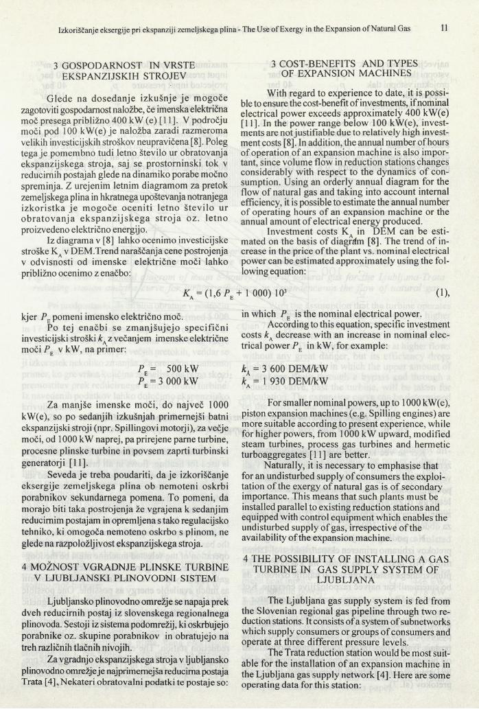
naj večji mogoči pretok rnaks 60 000 m3rvstopni tlak P , 30-50 barprojektni vstopni tlak P\ 40 barizstopni tlak Pi 10 barizstopna temperatura Ti 15 °C
Če vzamemo za srednji vstopni tlak 40 bar, moramo, za teoretično (izentropno) ekspanzijo do končnega tlaka 10 bar, plin segreti na 120 °C. Za dejansko ekspanzijo, pri notranjem izkoristku 80 %, pa leži vstopna temperatura 20 K niže (sl. 6).
maximum possible flow maks 60 000 m3tinput pressure Pi 30-50 barprojected input pressure Pi 40 baroutput pressure Pi lObaroutput temperature t2 15 °C
If a mean input pressure of 40 bar is assumed, the gas must be heated to 120 °C for theoretical (isenthropic) expansion to a final pressure of 10 bar. For actual expansion with an internal efficiency of 80 %, the inlet temperature is lower by 20 K (Fig. 6).
e n t r o p i j a ( s ) k J / ( k g K )SI. 6. Potek idealne in realne ekspanzije v plinovodnem sistemu 40/10 bar
Fig. 6. The ideal and real expansion curves for the gas supply system, 40/10 bar
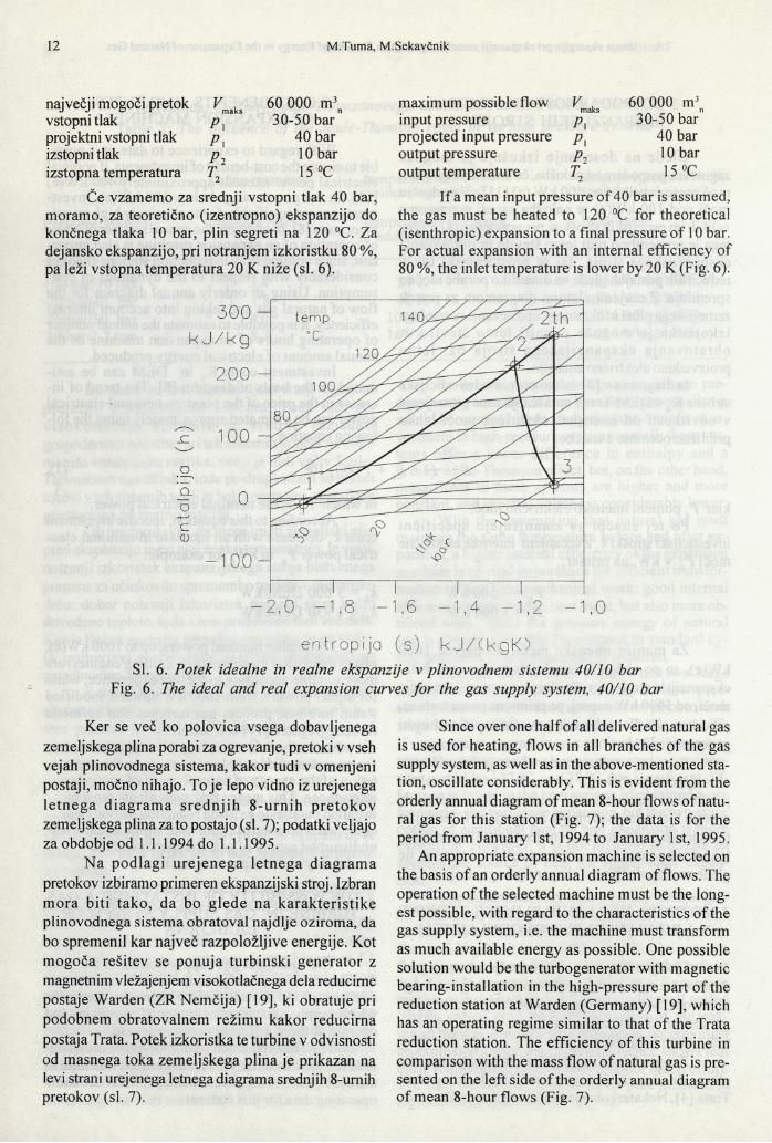
Ker se več ko polovica vsega dobavljenega zemeljskega plina porabi za ogrevanje, pretoki v vseh vejah plinovodnega sistema, kakor tudi v omenjeni postaji, močno nihajo. To je lepo vidno iz urejenega letnega d iagram a sredn jih 8-urnih p retokov zemeljskega plina za to postajo (sl. 7); podatki veljajo za obdobje od 1.1.1994 do 1.1.1995.
Na podlagi urejenega letnega diagram a pretokov izbiramo primeren ekspanzijski stroj. Izbran m ora biti tako, da bo glede na karakteristike plinovodnega sistema obratoval najdlje oziroma, da bo spremenil kar največ razpoložljive energije. Kot mogoča rešitev se ponuja turbinski generator z magnetnim vležajenjem visokotlačnega dela reducime postaje Warden (ZR Nemčija) [19], ki obratuje pri podobnem obratovalnem režimu kakor reducirna postaja Trata. Potek izkoristka te turbine v odvisnosti od masnega toka zemeljskega plina je prikazan na levi strani urejenega letnega diagrama srednjih 8-urnih pretokov (sl. 7).
Since over one half of all delivered natural gas is used for heating, flows in all branches of the gas supply system, as well as in the above-mentioned station, oscillate considerably. This is evident from the orderly annual diagram of mean 8-hour flows of natural gas for this station (Fig. 7); the data is for the period from January 1st, 1994 to January 1st, 1995.
An appropriate expansion machine is selected on the basis of an orderly annual diagram o f flows. The operation of the selected machine must be the longest possible, with regard to the characteristics of the gas supply system, i.e. the machine must transform as much available energy as possible. One possible solution would be the turbogenerator with magnetic bearing-installation in the high-pressure part o f the reduction station at Warden (Germany) [19], which has an operating regime similar to that of the Trata reduction station. The efficiency of this turbine in comparison with the mass flow of natural gas is presented on the left side o f the orderly annual diagram of mean 8-hour flows (Fig. 7).
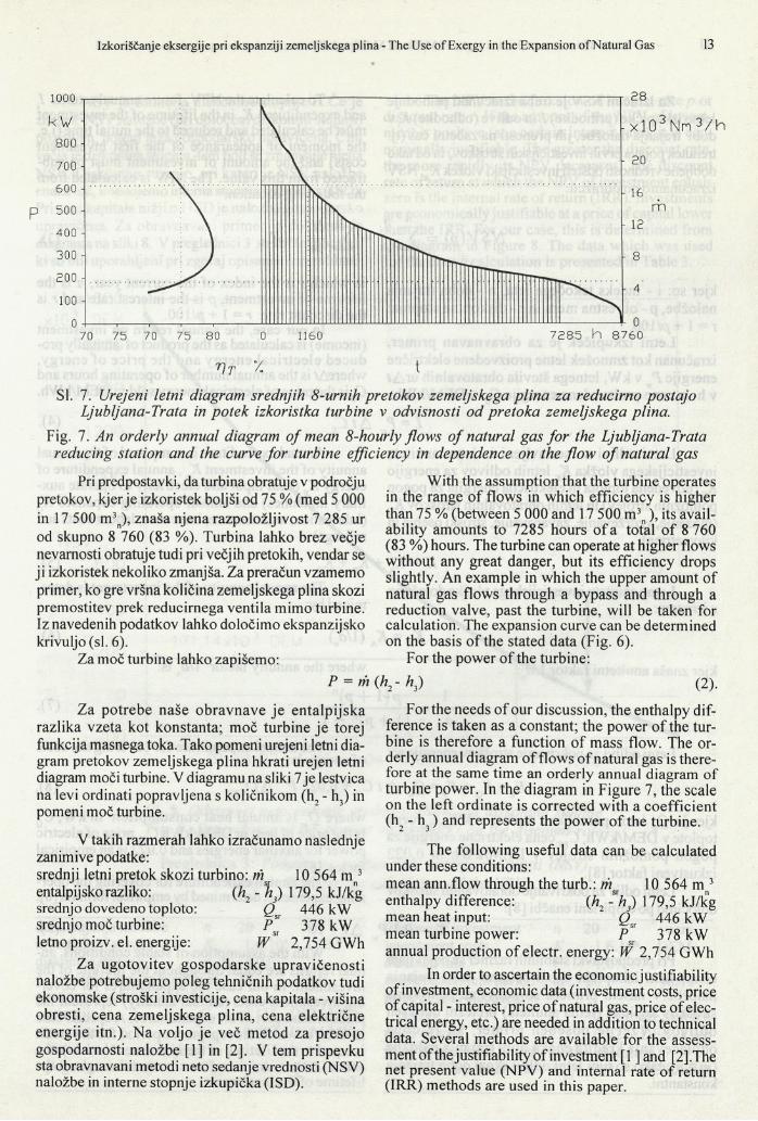
v t y. tSI. 7. Urejeni letni diagram srednjih 8-urnih pretokov zemeljskega plina za reducirno postajo
Ljubljana-Trata in potek izkoristka turbine v odvisnosti od pretoka zemeljskega plina.Fig. 7. An orderly annual diagram o f mean 8-hourly flows o f natural gas fo r the Ljubljana-Trata
reducing station and the curve fo r turbine efficiency in dependence on the flow o f natural gas
Pri predpostavki, da turbina obratuje v področju pretokov, kjer je izkoristek boljši od 75 % (med 5 000 in 17 500 m3n), znaša njena razpoložljivost 7 285 ur od skupno 8 760 (83 %). Turbina lahko brez večje nevarnosti obratuje tudi pri večjih pretokih, vendar se ji izkoristek nekoliko zmanjša. Za preračun vzamemo primer, ko gre vršna količina zemeljskega plina skozi premostitev prek reducirnega ventila mimo turbine. Iz navedenih podatkov lahko določimo ekspanzijsko krivuljo (sl. 6).
Za moč turbine lahko zapišemo:P = m
With the assumption that the turbine operates in the range o f flows in which efficiency is higher than 75 % (between 5 000 and 17 500 m3n ), its availability amounts to 7285 hours o f a total of 8 760 (83 %) hours. The turbine can operate at higher flows without any great danger, but its efficiency drops slightly. An example in which the upper amount of natural gas flows through a bypass and through a reduction valve, past the turbine, will be taken for calculation. The expansion curve can be determined on the basis o f the stated data (Fig. 6).
For the power o f the turbine:
V K ) (2).Za potrebe naše obravnave je entalpijska
razlika vzeta kot konstanta; moč turbine je torej funkcija masnega toka. Tako pomeni urejeni letni diagram pretokov zemeljskega plina hkrati urejen letni diagram moči turbine. V diagramu na sliki 7 je lestvica na levi ordinati popravljena s količnikom (h, - h3) in pomeni moč turbine.
V takih razmerah lahko izračunamo naslednje zanimive podatke:srednji letni pretok skozi turbino: m r 10 564 m 3 entalpijsko razliko: (h2 - h j) 179,5 kJ/kgsrednjo dovedeno toploto: Q 446 kWsrednjo moč turbine: P ’ 378 kWletno proizv. el. energije: W 2,754 GWh
Za ugotovitev gospodarske upravičenosti naložbe potrebujemo poleg tehničnih podatkov tudi ekonomske (stroški investicije, cena kapitala - višina obresti, cena zemeljskega plina, cena električne energije itn.). Na voljo je več metod za presojo gospodarnosti naložbe [1] in [2], V tem prispevku sta obravnavani metodi neto sedanje vrednosti (NSV) naložbe in interne stopnje izkupička (ISD).
For the needs o f our discussion, the enthalpy difference is taken as a constant; the power o f the turbine is therefore a function o f mass flow. The orderly annual diagram of flows of natural gas is therefore at the same time an orderly annual diagram of turbine power. In the diagram in Figure 7, the scale on the left ordinate is corrected with a coefficient (ho - h3 ) and represents the power o f the turbine.
The following useful data can be calculated under these conditions:mean ann.flow through the turb.: wsr 10 564 m 3 enthalpy difference: (h2 -h j) 179,5 kJ/kgmean heat input: Q 446 kWmean turbine power: p s 378 kWannual production o f electr. energy: W 2,754 GWh
In order to ascertain the economic justifiability of investment, economic data (investment costs, price of capital - interest, price o f natural gas, price o f electrical energy, etc.) are needed in addition to technical data. Several methods are available for the assessment of the justifiability of investment [1 ]and [2].The net present value (NPV) and internal rate of return (IRR) methods are used in this paper.
Za izračun NSV je treba izračunati prihodnje letne izkupičke (prihodke) I. in odlive (odhodke) K. v dobi trajanja naložbe, jih prenesti na začetni čas (tj. trenutek pojava prvih investicijskih stroškov) in od tako dobljene vrednosti odšteti investicijski vložek KA. NSV izračunamo po obrazcu:
To calculate the NPV, future annual returns I. and expenditures K. in the lifetime of the investment must be calculated and reduced to the initial time (i.e. the moment o f appearance o f the first investment costs) and the amount o f investment must be subtracted from this value. The NPV is calculated from the following equation:
NSV{p) =i= 1 t'=1
(3),
kjer so: i - indeks tekočega leta, n - doba trajanja naložbe, p - obrestna mera in r - diskontna stopnja: r = 1 + />/100.
Letni izkupiček je za obravnavan primer, izračunan kot zmnožek letne proizvedene električne energije Psr v kW, letnega števila obratovalnih urA t v h in cene proizvedene energije CE v DEM/kWh:
in which i is the index o f the current year, n is the lifetime of investment, p is the interest rate and r is the discount rate: r — 1 + pi 100.
In our case, the annual return on investment (income) is calculated as the product of annually produced electrical energy and the price o f energy, whereAt is the annual number o f operating hours and CE is the price of electrical energy sold in DEM/kWh.
I. = P A /C „i sr E(4).
Letni odlivi so sestavljeni iz letne anuitete investicijskega vložka Kk letnih odlivov za energijo Ke (dovedena toplota in električna energija za pogon pomožnih strojev) in letnih obratovalnih stroškov K0 (mazanje, vzdrževanje, zavarovanje, stroški osebja in kilometrine):
Annual expenditure is composed of the annual annuity of the investment K ., annual expenditure of energy K (heat input and electricity to operate auxiliary machines) and annual operating expenses K0 (lubrication, maintenance, insurance, labour costs and mileage):
K = Kk P K e + K0 (5).
Letno anuiteto investicijskega vložka določimo z izrazom:
The annual annuity of the investment is determined by:
Kk = Ka (1 /a ) (6),
kjer znaša anuitetni faktor 1 la \ where the annuity factor l /a n is:
J _ _ P ( ! + pT (7).an ( l + p ) " - l
Letni odlivi za pokrivanje stroškov energije so: of energy^ s.nnua* exPenc *ture f° r covering the costs
K = K + K = Q„ A t Cn + 0,022 P A t C „ (8),
kjer je Qsr letna porabljena toplota v kW, CQ cena toplote v DEM/kWh, CES cena električne energije za pogon pomožnih strojev v DEM/kWh in 0,022 izkustveni faktor [8],
Letni odliv za pokrivanje obratovalnih stroškov določimo po empirični enačbi [8]:
*o = 0,l P,Pri predpostavki stabilnih razmer se pojavljajo
enaki letni izkupički skozi celotno dobo trajanja naložbe.V našem primeru so odlivi za pokrivanje stroškov kapitala (letna anuiteta) pretežni del vseh odlivov. V zet je poseben prim er, ko je doba odplačevanja kredita enaka dobi trajanja naložbe (m = «); tako so tudi letni odlivi skozi dobo trajanja konstantni.
where g sr >s annual heat consum ption in kW, CQ is the price of heat in DEM/kWh CES price of electric power for auxiliar energies and 0.022 is an empirical factor [8],
The annual expenditure for covering the operating expenses is determined by empirical formula [8]:
A / + 1 0 4 (9).With the assumption of stable conditions, an
nual returns are equal throughout the lifetime of the investment. In our case the expenditures for covering investment costs (annual annuity) represent the predominant part of all expenditures. A special case is taken in which the repayment period for the credit is equal to the lifetime of the investment (m = «); the annual returns are therefore constant throughout the lifetime of the investment.
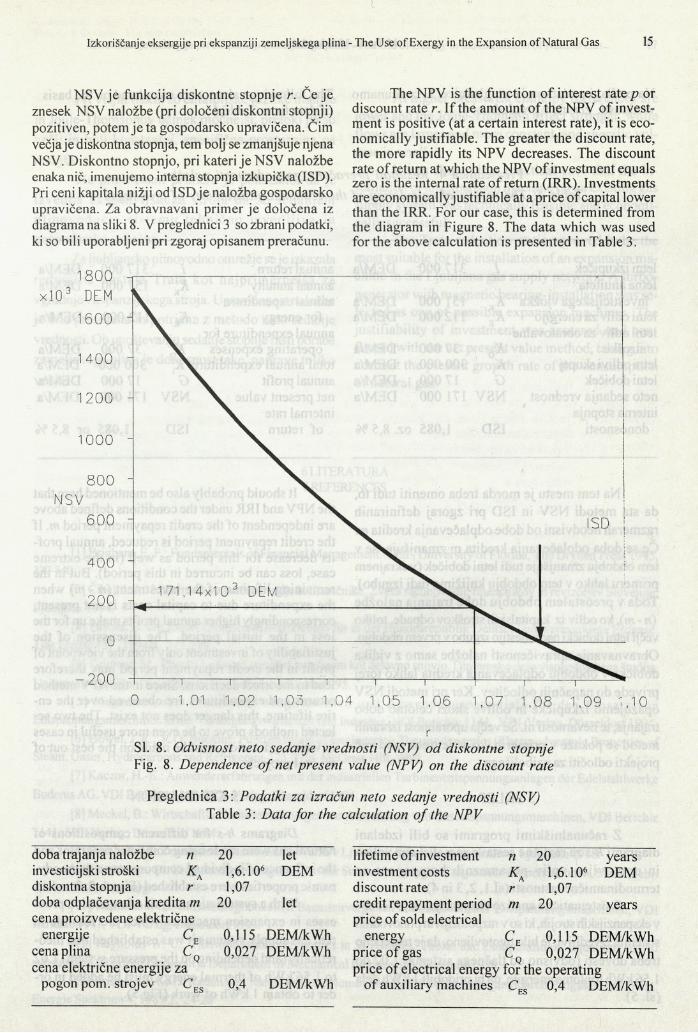
NSV je funkcija diskontne stopnje r. Če je znesek NSV naložbe (pri določeni diskontni stopnji) pozitiven, potem je ta gospodarsko upravičena. Čim večja je diskontna stopnja, tem bolj se zmanjšuje njena NSV. Diskontno stopnjo, pri kateri je NSV naložbe enaka nič, imenujemo interna stopnja izkupička (ISD). Pri ceni kapitala nižji od ISD je naložba gospodarsko upravičena. Za obravnavani primer je določena iz diagrama na sliki 8. V preglednici 3 so zbrani podatki, ki so bili uporabljeni pri zgoraj opisanem preračunu.
The NPV is the function o f interest rate p or discount rate r. If the amount o f the NPV of investment is positive (at a certain interest rate), it is economically justifiable. The greater the discount rate, the more rapidly its NPV decreases. The discount rate o f return at which the NPV of investment equals zero is the internal rate of return (IRR). Investments are economically justifiable at a price of capital lower than the IRR. For our case, this is determined from the diagram in Figure 8. The data which was used for the above calculation is presented in Table 3.
SI. 8. Odvisnost neto sedanje vrednosti (NSV) od diskontne stopnje Fig. 8. Dependence o f net present value (NPV) on the discount rate
Preglednica 3: Podatki za izračun neto sedanje vrednosti (NSV) Table 3: Data for the calculation o f the NPV
doba trajanja naložbe n 20 letinvesticijski stroški 1,6.106 DEMdiskontna stopnja r 1,07doba odplačevanja kredita m cena proizvedene električne
20 let
energije C, 0,115 DEM/kWhcena plina 0,027 DEM/kWhcena električne energije za
pogon pom. strojev cES 0,4 DEM/kWh
lifetime of investment n 20 yearsinvestment costs K , 1,6.106 DEMdiscount rate r 1,07credit repayment period price o f sold electrical
m 20 years
energy c E 0,115 DEM/kWhprice of gas c n 0,027 DEM/kWhprice o f electrical energy for the operating
of auxiliary machines cES 0,4 DEM/kWh
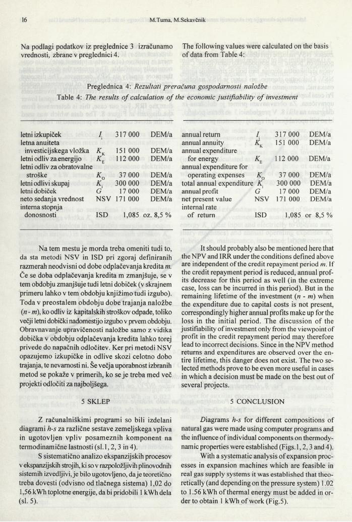
Na podlagi podatkov iz preglednice 3 izračunamo The following values were calculated on the basis vrednosti, zbrane v preglednici 4. o f data from Table 4:
Preglednica 4: Rezultati preračuna gospodarnosti naložbe Table 4: The results o f calculation o f the economic justifiability o f investment
letni izkupiček letna anuiteta
I. 317 000 DEM/a
investicijskega vložka 151 000 DEM/aletni odliv za energijo letni odliv za obratovalne
112 000 DEM/a
stroške K o 37 000 DEM/aletni odlivi skupaj k : 300 000 DEM/alemi dobiček G 17 000 DEM/aneto sedanja vrednost interna stopnja
NSV 171 000 DEM/a
donosnosti ISD 1,085 oz. 8,5 %
Na tem mestu je morda treba omeniti tudi to, da sta metodi NSV in ISD pri zgoraj definiranih razmerah neodvisni od dobe odplačevanja kredita m. Če se doba odplačevanja kredita m zmanjšuje, se v tem obdobju zmanjšuje tudi letni dobiček (v skrajnem primeru lahko v tem obdobju knjižimo tudi izgubo). Toda v preostalem obdobju dobe trajanja naložbe (;n - m), ko odliv iz kapitalskih stroškov odpade, toliko večji letni dobički nadomestijo izgubo v prvem obdobju. Obravnavanje upravičenosti naložbe samo z vidika dobička v obdobju odplačevanja kredita lahko torej privede do napačnih odločitev. Ker pri metodi NSV opazujemo izkupičke in odlive skozi celotno dobo trajanja, te nevarnosti ni. Še večja uporabnost izbranih metod se pokaže v primerih, ko se je treba med več projekti odločiti za najboljšega.
5 SKLEP
Z računalniškimi programi so bili izdelani diagrami h-s za različne sestave zemeljskega vpliva in ugotovljen vpliv posameznih kom ponent na termodinamične lastnosti (sl. 1,2,3 in 4).
S sistematično analizo ekspanzijskih procesov v ekspanzijskih strojih, ki so v razpoložljivih plinovodnih sistemih izvedljivi, je bilo ugotovljeno, da je teoretično treba dovesti (odvisno od tlačnega sistema) 1,02 do 1,56 kWh toplotne energije, da bi pridobili 1 kWh dela (sl. 5).
annual return / 317 000 DEM/aannual annuity annual expenditure
< 151 000 DEM/a
for energyannual expenditure for
112 000 DEM/a
operating expenses 37 000 DEM/atotal annual expenditure K 300 000 DEM/aannual profit G 17 000 DEM/anet present value internal rate
NSV 171 000 DEM/a
of return ISD 1,085 or 8,5%
It should probably also be mentioned here that theNPV and IRR under the conditions defined above are independent of the credit repayment period m. If the credit repayment period is reduced, annual profits decrease for this period as well (in the extreme case, loss can be incurred in this period). But in the remaining lifetime of the investment (n - m) when the expenditure due to capital costs is not present, correspondingly higher annual profits make up for the loss in the initial period. The discussion o f the justifiability of investment only from the viewpoint of profit in the credit repayment period may therefore lead to incorrect decisions. Since in the NPV method returns and expenditures are observed over the entire lifetime, this danger does not exist. The two selected methods prove to be even more useful in cases in which a decision must be made on the best out of several projects.
5 CONCLUSION
Diagrams h-s for different compositions of natural gas were made using computer programs and the influence of individual components on thermodynamic properties were established (Figs. 1,2,3 and 4).
With a systematic analysis o f expansion processes in expansion machines which are feasible in real gas supply systems it was established that theoretically (and depending on the pressure system) 1.02 to 1.56 kWh of thermal energy must be added in order to obtain 1 kWh o f work (Fig.5).
Pri višjih tlakih so entalpijske razlike manjše in Joule-Thomsonov učinek močnejši, pretoki pa so večji in bolj konstantni, specifična prostornina pa manjša.
Na praktičnem primeru je pokazano, da je izvedba ekspanzijskega stroja na že sedanjem plinovodnem sistem u tehn ično izved ljiva in gospodarsko uspešna.
Za ljubljansko plinovodno omrežje seje izkazala reducirna postaja Trata kot najprim ernejša za vgradnjo ekspanzijskega stroja. Upravičenost naložbe je bila presojena in potrjena z metodo neto sedanje vrednosti. Ob upoštevanju sedanje stopnje rasti porabe zemeljskega plina je donosnost take naprave toliko večja.
At higher pressures, enthalpy differences are lower and the Joule-Thomson effect stronger, while flows are larger and more constant, and specific volume is smaller.
It was shown in a practical case that the installation of an expansion machine on an existing gas supply system was technically feasible and economically successful.
The Trata reduction station proved to be the most suitable for the installation o f an expansion machine in the Ljubljana gas supply network. A turbogenerator with magnetic bearing-installation was selected as one o f possible expansion machines. The justifiability of investment was assessed and confirmed with the net present value method, taking into account the present growth rate o f the consumption of natural gas.
6 LITERATURA 6 REFERENCES
[1] Brigham, E. F.: Fundamentals ofFinancial Management. 7 Ed., University ofFlorida, The Dryden Press 1995, 337-340.
[2] Čibej, J. A.: Matematika za računovodje in finančnike. Zveza računovodij, finančnikov in revizorjev Slovenije, Ljubljana 1994.
[3] Fasold, H. G.: Joule-Thomson-Koeffizienten für in der Bundesrepublik Deutschland vermarktete Erdgase. Gas Erdgas 135,1994/4, 212-219.
[4] Grebenc, M. : Plinska turbina z zemeljskim plinom kot delovno snovjo. Diplomsko delo visokošolskega študija. Univerza v Ljubljani, Fakulteta za strojništvo, Ljubljana 1995.
[5] Hagedorn, G.: Technische M öglichkeiten und A nw endungspotentiale für den E insatz von Entspannungsmaschinen in der Versorgungswirtschaft und Industrie. VDI Berichte 1141, VDI-Verlag, Düsseldorf 1994.
[6] Howel, J. R., R.O. Buckius: Fundamentals of Engineering Thermodynamics (Thermodynamic Properties of Steam, Gases, Hydrocarbons and Refrigerant-12), 2 Ed. McGraw Hill, 1992.
[7] Kaczor, H.-E.: Anwendererfahrungen mit der industriellen Turbinenentspannungsanlagen der Edelstahlwerke Buderus AG. VDI Berichte 1141, VDl-Verlag, Düsseldorf 1994.
[8] Meckel, B.: Wirtschaftlichkeitsbetrachtungen zur Anwendung von Gasentspannungsmaschinen, VDI Berichte 1141, VDI Verlag, Düsseldorf 1994.
[9] Oprešnik,M.: Termodinamika zmesi. Univerza v Ljubljani, Fakulteta za strojništvo, Ljubljana 1988.[10] Rathmann, D.: Erdgasentspannungsanlagen zur Stromerzeugung in Erdgasübemahmerstationen, Stand: Febr.
1994, ASUE, Hamburg.[11] Rathmann, D.: Einsatzmöglichkeiten Bauartenvergleich unterschiedlicher Entspannungsmaschinen, VDI
Berichte 1141, VDI-Verlag, Düsseldorf 1994.[12] Reynolds W. C.: Thermodynamic Properties in SI (Graphs, Tables anc Computational Equations for 40
substances), Stanford University, Department of Mechanical Engineering, Stanford 1979.[13] Rostek, H. A., D. Rathmann: Nahe Hundert; Nomogramme für Stromerzeugung durch Erdgasentspannung,
Energie Spektrum 4,1989/2, 24-28
[14] Stoli, H.: Experience with the Commissioning of a Natural Gas Power Recovery Turbine. Proceedings of the International Gas Turbine and Aeroengine Congress and Exposition. 92-GT-266, Köln,01 .-04.06. 1992.
[15] Tuma M., M. Sekavčnik: Stromerzeugung mit den Erdgas-Entspannungsmaschinen, Brenstoff - Wärme - Kraft 48, v tisku.
[16] Ullmann’s Encyclopedia of Industrial Chemistry, 5 Ed. A16&17.[ 17] Urban, M., B. Fischer: Nachrüstung einer 4 MW Erdgas-Entspannungsanlage zur Stromerzeugung im Kraftwerk
Main-Wiesbaden, VDI Berichte 1141, VDI-Verlag, Düsseldorf 1994.[18] Weßing, W.: Zündgrenzen von Erdgas in Abhängigkeit von der Gasbeschaffenheit, Gas Erdgas 135,1994/ 2,
104-108[19] Willmloth, G.: Magnetgelagerte Turbogeneratoren (MTG), VDI Berichte 1141,125-145, VDI Verlag, Düsseldorf
1994.
Naslov avtorjev: prof. dr. Matija Tuma, dipl. inž. Authors' Address: Prof. Dr. Matija Tuma, Dipl. Ing.Miha Sekavčnik, dipl. inž. Fakulteta za strojništvo Univerze v Ljubljani Aškerčeva 6 1000 Ljubljana
Miha Sekavčnik, Dipl. Ing.Faculty of Mechanical Engineering University of Ljubljana Aškerčeva 61000 Ljubljana, Slovenia
Received:Prejeto: 2.4.1996 Sprejeto:
Accepted: 26.2.1997