Embed Size (px)
Citation preview
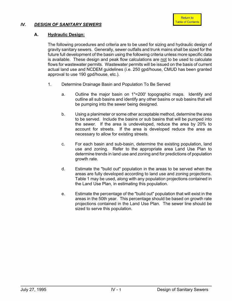
IV. DESIGN OF SANITARY SEWERS
A. Hydraulic Design:
The following procedures and criteria are to be used for sizing and hydraulic design of gravity sanitary sewers. Generally, sewer outfalls and trunk mains shall be sized for the future full development of the basin using the following criteria unless more specific data is available. These design and peak flow calculations are not to be used to calculate flows for wastewater permits. Wastewater permits will be issued on the basis of current actual land use and NCDEM guidelines (i.e. 250 gpd/house, CMUD has been granted approval to use 190 gpd/house, etc.).
1. Determine Drainage Basin and Population To Be Served
a. Outline the major basin on 1"=200' topographic maps. Identify and
outline all sub basins and identify any other basins or sub basins that will be pumping into the sewer being designed.
b. Using a planimeter or some other acceptable method, determine the area
to be served. Include the basins or sub basins that will be pumped into the sewer. If the area is undeveloped, reduce the area by 20% to account for streets. If the area is developed reduce the area as necessary to allow for existing streets.
c. For each basin and sub-basin, determine the existing population, land
use and zoning. Refer to the appropriate area Land Use Plan to determine trends in land use and zoning and for predictions of population growth rate.
d. Estimate the "build out" population in the areas to be served when the
areas are fully developed according to land use and zoning projections. Table 1 may be used, along with any population projections contained in the Land Use Plan, in estimating this population.
e. Estimate the percentage of the "build out" population that will exist in the
areas in the 50th year. This percentage should be based on growth rate projections contained in the Land Use Plan. The sewer line should be sized to serve this population.
July 27, 1995 IV - 1 Design of Sanitary Sewers
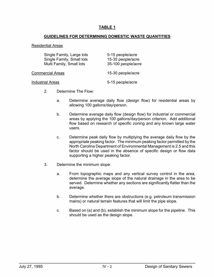
TABLE 1 GUIDELINES FOR DETERMINING DOMESTIC WASTE QUANTITIES
Residential Areas
Single Family, Large lots 5-15 people/acre Single Family, Small lots 15-35 people/acre Multi Family, Small lots 35-100 people/acre
Commercial Areas 15-30 people/acre
Industrial Areas 5-15 people/acre
2. Determine The Flow:
a. Determine average daily flow (design flow) for residential areas by
allowing 100 gallons/day/person.
b. Determine average daily flow (design flow) for industrial or commercial areas by applying the 100 gallons/day/person criterion. Add additional flow based on research of specific zoning and any known large water users.
c. Determine peak daily flow by multiplying the average daily flow by the
appropriate peaking factor. The minimum peaking factor permitted by the North Carolina Department of Environmental Management is 2.5 and this factor should be used in the absence of specific design or flow data supporting a higher peaking factor.
3. Determine the minimum slope:
a. From topographic maps and any vertical survey control in the area,
determine the average slope of the natural drainage in the area to be served. Determine whether any sections are significantly flatter than the average.
b. Determine whether there are obstructions (e.g. petroleum transmission
mains) or natural terrain features that will limit the pipe slope.
c. Based on (a) and (b), establish the minimum slope for the pipeline. This should be used as the design slope.
July 27, 1995 IV - 2 Design of Sanitary Sewers

4. Size the Sanitary Sewer Pipe:
a. Use the peak daily flow for calculations with pipe flowing full. This is equilavent to using average daily flow (design flow) with the pipe flowing approximately 40% full.
b. Use Manning Equation or Charts to determine pipe size.
Q = 1.486 A R
2/3 S
1/2
n
Where n = .013 R = hydraulic radius = cross sectional area
wetted perimeter S = slope A = Cross sectional area of pipe
c. Check the velocity flowing full
V= Q/A Velocity must be > 2 fps and < 10 fps
d. Check the pipe size and slope against Table 2 and adjust pipe size as
required to meet the minimum design slope.
July 27, 1995 IV - 3 Design of Sanitary Sewers
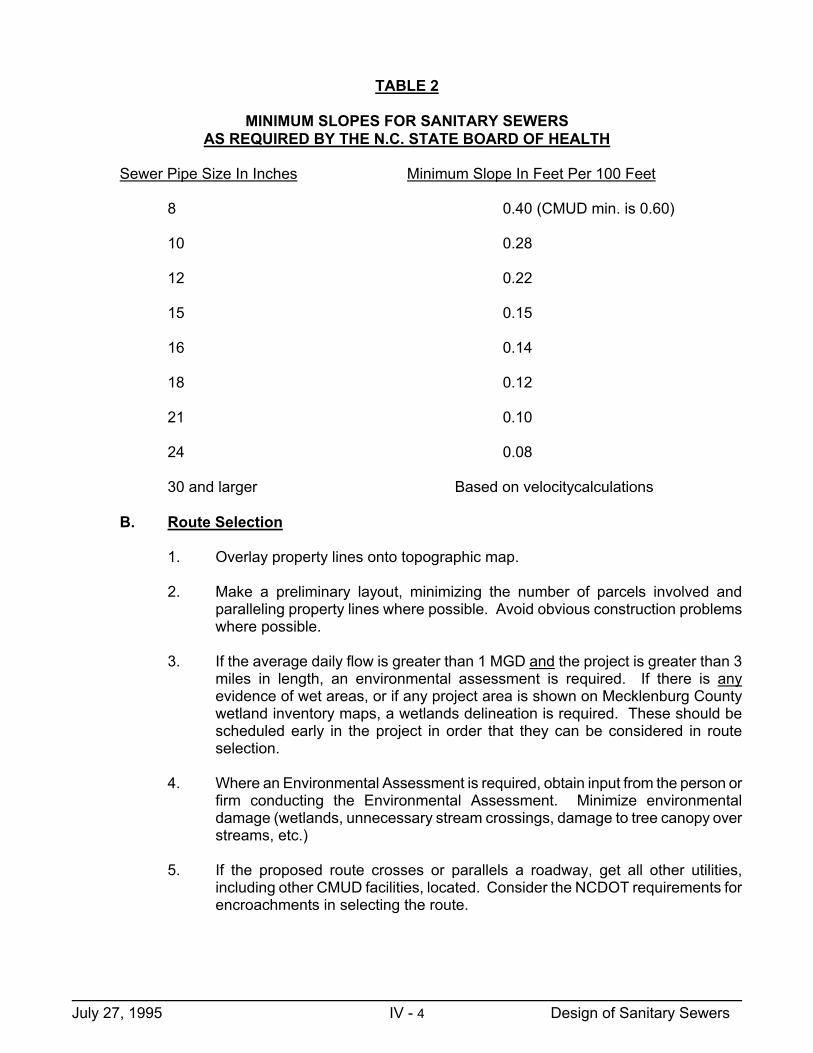
TABLE 2 MINIMUM SLOPES FOR SANITARY SEWERS AS REQUIRED BY THE N.C. STATE BOARD OF HEALTH
Sewer Pipe Size In Inches Minimum Slope In Feet Per 100 Feet
8 0.40 (CMUD min. is 0.60)
10 0.28
12 0.22
15 0.15
16 0.14
18 0.12
21 0.10
24 0.08
30 and larger Based on velocitycalculations
B. Route Selection
1. Overlay property lines onto topographic map.
2. Make a preliminary layout, minimizing the number of parcels involved and paralleling property lines where possible. Avoid obvious construction problems where possible.
3. If the average daily flow is greater than 1 MGD and the project is greater than 3
miles in length, an environmental assessment is required. If there is any evidence of wet areas, or if any project area is shown on Mecklenburg County wetland inventory maps, a wetlands delineation is required. These should be scheduled early in the project in order that they can be considered in route selection.
4. Where an Environmental Assessment is required, obtain input from the person or
firm conducting the Environmental Assessment. Minimize environmental damage (wetlands, unnecessary stream crossings, damage to tree canopy over streams, etc.)
5. If the proposed route crosses or parallels a roadway, get all other utilities,
including other CMUD facilities, located. Consider the NCDOT requirements for encroachments in selecting the route.
July 27, 1995 IV - 4 Design of Sanitary Sewers
6. Walk the project with survey party. Modify preliminary routing as necessary
based on field observation of terrain features, environmental considerations, and property damage. Maintain sufficient distance from creek to protect pipe from washout.
7. Provide preliminary layout to survey party and if applicable, to firm or person
conducting the Environmental Assessment. C. Survey Requirements
All sanitary sewer lines shall be field surveyed under the supervision of a surveyor registered in North Carolina.
1. Vertical control shall be tied to NGS, NCGS or established CMUD vertical control
points. Temporary bench marks shall be established at each proposed manhole and tied back to the established vertical control with a maximum error of 0.03’ M , where M is the number of miles of level loop. The elevation base, NAVD 27 or NAVD 88, shall be indicated on the cover sheet of each set of plans.
2. Horizontal control shall be tied to North Carolina Grid Coordinates.
3. Centerline shall be cut and staked. Iron hubs shall be installed at all angle points
and at all manhole locations.
4. Profile data shall include centerline shots at manholes and at 50 foot intervals along centerline and at all grade break points. When paralleling adjacent streams, stream bed elevations are required at each manhole.
5. Where cut or fill slopes are necessary for construction, cross sections shall be
provided at fifty foot intervals along the centerline.
6. The bearing of each sewer reach (manhole to manhole) shall be shown as degrees-minutes-seconds (to least count of instrument used), and the distance between manholes shall be shown to the nearest 0.01 foot.
Sewer lines in new subdivision streets are excluded from these requirements when the sewer plan and profile is tied to proposed street layouts in a manner acceptable to CMUD. However, before construction begins, the street rough grading must be completed, the sewer lines must be construction staked and cut sheets must be provided to CMUD. Cut sheets shall be signed by an NC registered surveyor or by the contractor's designated responsible employee.
D. Rights-Of-Way And Construction Easements
1. Permanent right-of-way and temporary construction easements shall be provided
according to Table 3. Temporary construction easements should be increased for difficult construction areas (e.g. sewers on steep slopes).
July 27, 1995 IV - 5 Design of Sanitary Sewers

Construction within wetlands shall be limited to a disturbed width of 40', in accordance with Nationwide Permit No. 12 issued by the Corps of Engineers.
2. When a sewer must closely parallel a creek, two thirds to three fourths of the
construction easement shall be on the side away from the creek.
3. A separate right-of-way map shall be prepared for each individual property crossed. All maps shall be on standard CMUD sheets, shall conform to the requirements of the standards of practice for land surveying in North Carolina, Section 1600 of The Board Rules and shall contain the following:
a. The entire property boundary shall be shown on the map with the
proposed right-of-way clearly shown. For large properties, right-of-way details must be shown by separate insets at reduced scale. Not to scale insets may be used when necessary to clearly convey details.
b. Every point where the sewer center line or right-of-way crosses a
property line must be tied to an identifiable property corner.
c. The property owners name, deed book and page where the deed is recorded, and the current property tax code must be shown on each map, including adjoining parcels.
d. All manhole locations must be shown, whether at angle points or on line.
Show Bearings between angle points and centerline distances along lines.
e. Widths for permanent rights-of-way and temporary construction
easements must be shown and labeled.
f. The parcels on a project shall be numbered sequentially, beginning with #1 at the downstream end. The parcel number shall appear in a triangle above the owner's name and in the title block.
g. All maps must be on 8�" x 14" vellum or mylar with a standard CMUD
title block. The title block shall include the following:
a. Title as: Sanitary Sewer to Serve: Project Name, or Water Meter Easement to Serve Project Name.
b. Property of current property owner, Job number, file number and
scale.
h. Include a vicinity map and a north arrow with basis.
i. Proposed right-of-way must be shaded.
July 27, 1995 IV - 6 Design of Sanitary Sewers
j. Submit an original map and one copy with the original signature and original seal of the N.C. Registered Surveyor, as required by G.S. 47-30(M). In addition, seven (7) blueline copies are required.
4. Check right-of-way maps against construction plans and make sure they agree.
When a revision is made, make sure that both the plans and the affected right-of-way maps are changed and that the changes are recorded in the revision blocks on both documents.
5. When paralleling property lines, make the permanent right-of-way boundary
contiguous with the property line. Try to keep the construction easement on the same property. Don't create a new parcel just for a construction easement unless the topography requires it (e.g. where the easement would otherwise be in a creek).
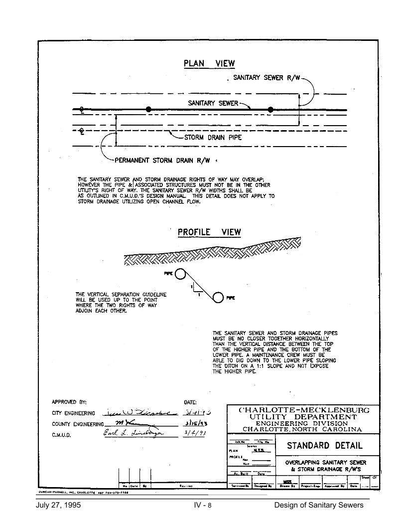
6. The sanitary sewer right-of-way may overlap storm drainage right-of-way
according to the following Standard Detail:
July 27, 1995 IV - 7 Design of Sanitary Sewers
July 27, 1995 IV - 8 Design of Sanitary Sewers
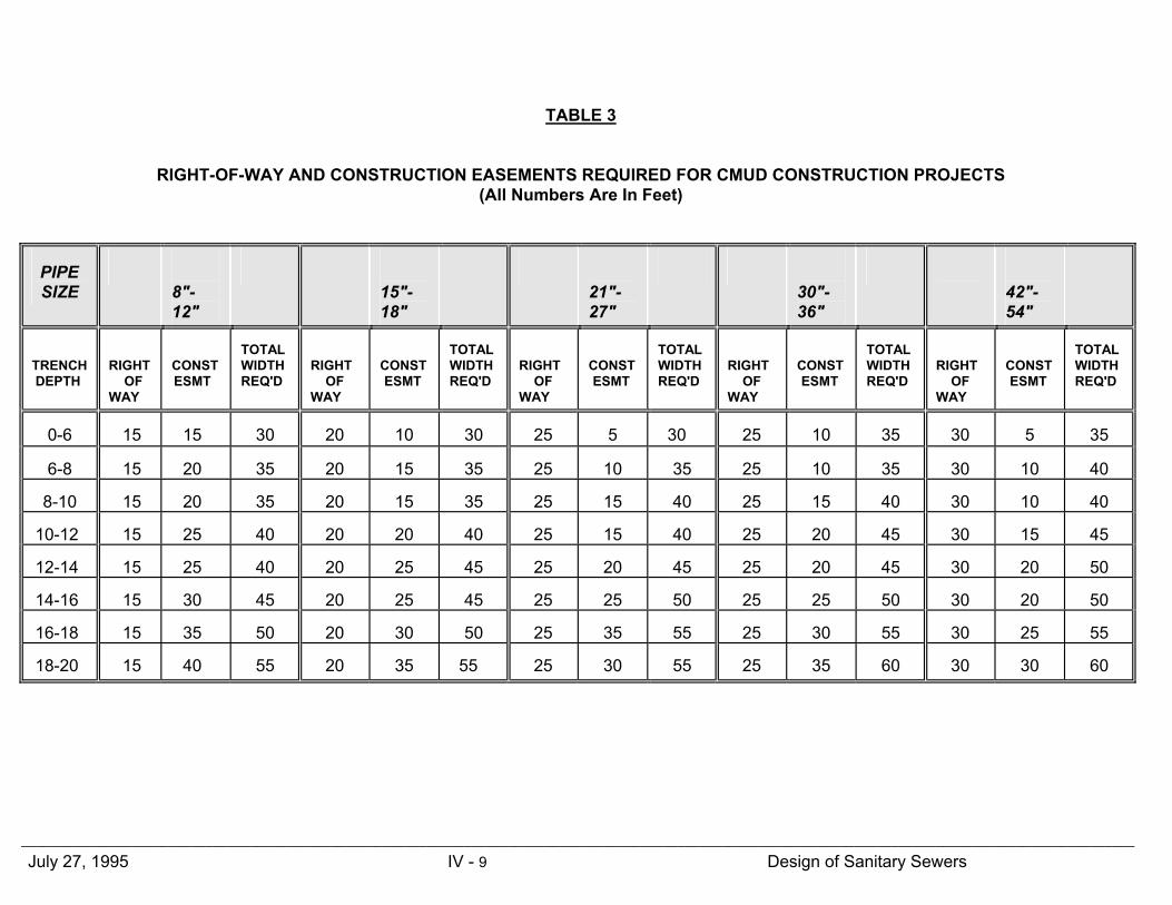
TABLE 3 RIGHT-OF-WAY AND CONSTRUCTION EASEMENTS REQUIRED FOR CMUD CONSTRUCTION PROJECTS (All Numbers Are In Feet)
PIPE SIZE
8"-12"
15"-18"
21"-27"
30"-36"
42"-54"
TRENCH DEPTH
RIGHT OF WAY
CONST ESMT
TOTAL WIDTH REQ'D
RIGHT OF WAY
CONST ESMT
TOTAL WIDTH REQ'D
RIGHT OF WAY
CONST ESMT
TOTAL WIDTH REQ'D
RIGHT OF WAY
CONST ESMT
TOTAL WIDTH REQ'D
RIGHT OF WAY
CONST ESMT
TOTAL WIDTH REQ'D
0-6
15
15
30
20
10
30
25
5
30
25
10
35
30
5
35
6-8
15
20
35
20
15
35
25
10
35
25
10
35
30
10
40
8-10
15
20
35
20
15
35
25
15
40
25
15
40
30
10
40
10-12
15
25
40
20
20
40
25
15
40
25
20
45
30
15
45
12-14
15
25
40
20
25
45
25
20
45
25
20
45
30
20
50
14-16
15
30
45
20
25
45
25
25
50
25
25
50
30
20
50
16-18
15
35
50
20
30
50
25
35
55
25
30
55
30
25
55
18-20
15
40
55
20
35
55
25
30
55
25
35
60
30
30
60
_______________________________________________________________________________________________________________________________________________________ July 27, 1995 IV - 9 Design of Sanitary Sewers
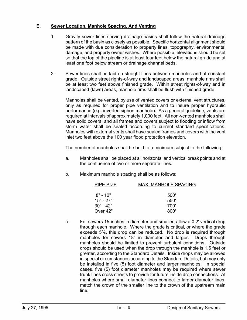
E. Sewer Location, Manhole Spacing, And Venting
1. Gravity sewer lines serving drainage basins shall follow the natural drainage pattern of the basin as closely as possible. Specific horizontal alignment should be made with due consideration to property lines, topography, environmental damage, and property owner wishes. Where possible, elevations should be set so that the top of the pipeline is at least four feet below the natural grade and at least one foot below stream or drainage channel beds.
2. Sewer lines shall be laid on straight lines between manholes and at constant
grade. Outside street rights-of-way and landscaped areas, manhole rims shall be at least two feet above finished grade. Within street rights-of-way and in landscaped (lawn) areas, manhole rims shall be flush with finished grade.
Manholes shall be vented, by use of vented covers or external vent structures, only as required for proper pipe ventilation and to insure proper hydraulic performance (e.g. inverted siphon manhole). As a general guideline, vents are required at intervals of approximately 1,000 feet. All non-vented manholes shall have solid covers, and all frames and covers subject to flooding or inflow from storm water shall be sealed according to current standard specifications. Manholes with external vents shall have sealed frames and covers with the vent inlet two feet above the 100 year flood protection elevation.
The number of manholes shall be held to a minimum subject to the following:
a. Manholes shall be placed at all horizontal and vertical break points and at
the confluence of two or more separate lines.
b. Maximum manhole spacing shall be as follows:
PIPE SIZE MAX. MANHOLE SPACING
8" - 12" 500' 15" - 27" 550' 30" - 42" 700' Over 42" 800'
c. For sewers 15-inches in diameter and smaller, allow a 0.2' vertical drop
through each manhole. Where the grade is critical, or where the grade exceeds 5%, this drop can be reduced. No drop is required through manholes for sewers 18" in diameter and larger. Drops through manholes should be limited to prevent turbulent conditions. Outside drops should be used when the drop through the manhole is 1.5 feet or greater, according to the Standard Details. Inside drops may be allowed in special circumstances according to the Standard Details, but may only be installed in five (5) foot diameter and larger manholes. In special cases, five (5) foot diameter manholes may be required where sewer trunk lines cross streets to provide for future inside drop connections. At manholes where small diameter lines connect to larger diameter lines, match the crown of the smaller line to the crown of the upstream main line.
July 27, 1995 IV - 10 Design of Sanitary Sewers
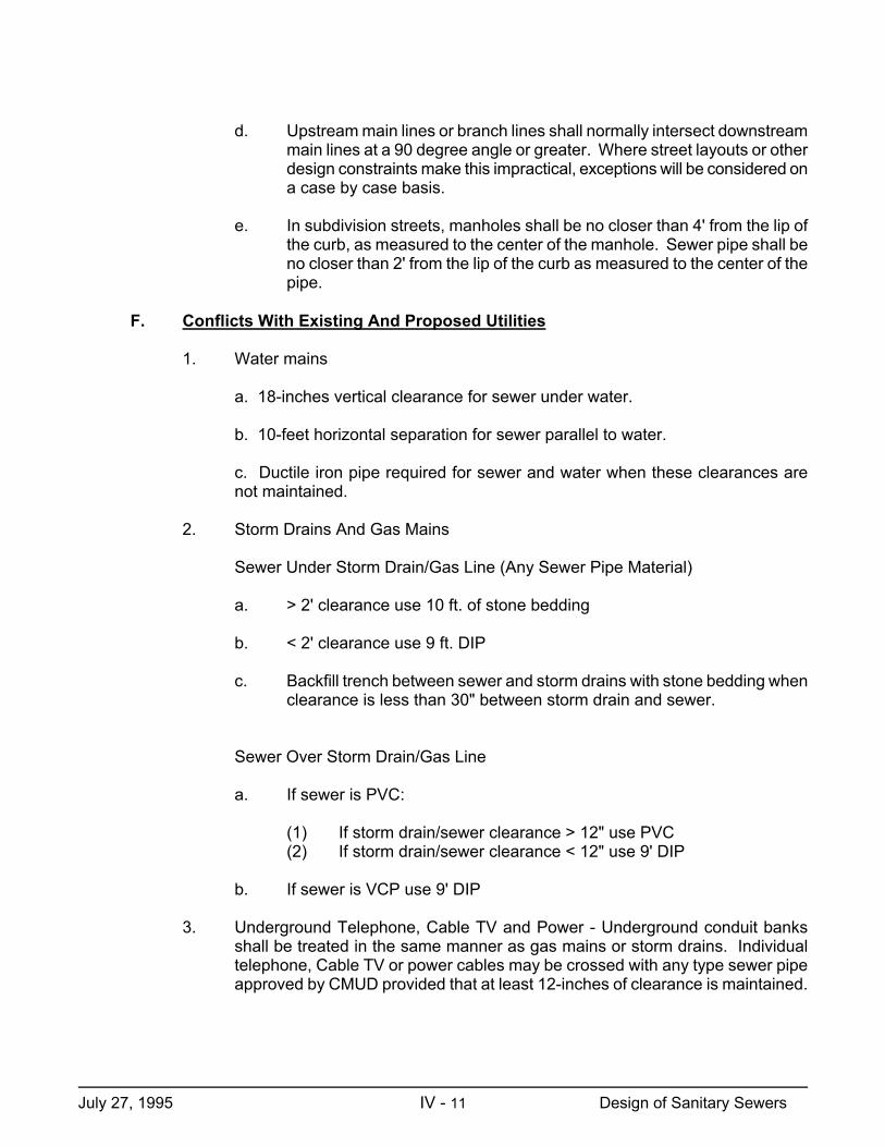
d. Upstream main lines or branch lines shall normally intersect downstream main lines at a 90 degree angle or greater. Where street layouts or other design constraints make this impractical, exceptions will be considered on a case by case basis.
e. In subdivision streets, manholes shall be no closer than 4' from the lip of
the curb, as measured to the center of the manhole. Sewer pipe shall be no closer than 2' from the lip of the curb as measured to the center of the pipe.
F. Conflicts With Existing And Proposed Utilities
1. Water mains
a. 18-inches vertical clearance for sewer under water.
b. 10-feet horizontal separation for sewer parallel to water.
c. Ductile iron pipe required for sewer and water when these clearances are not maintained.
2. Storm Drains And Gas Mains
Sewer Under Storm Drain/Gas Line (Any Sewer Pipe Material)
a. > 2' clearance use 10 ft. of stone bedding
b. < 2' clearance use 9 ft. DIP
c. Backfill trench between sewer and storm drains with stone bedding when
clearance is less than 30" between storm drain and sewer.
Sewer Over Storm Drain/Gas Line
a. If sewer is PVC:
(1) If storm drain/sewer clearance > 12" use PVC (2) If storm drain/sewer clearance < 12" use 9' DIP
b. If sewer is VCP use 9' DIP
3. Underground Telephone, Cable TV and Power - Underground conduit banks
shall be treated in the same manner as gas mains or storm drains. Individual telephone, Cable TV or power cables may be crossed with any type sewer pipe approved by CMUD provided that at least 12-inches of clearance is maintained.
July 27, 1995 IV - 11 Design of Sanitary Sewers
G. Depth And Structural Design
Maximum depths, trench width and bedding requirements are addressed in CMUD construction specifications (DS Section) for each type of approved pipe material. These are minimum requirements and do not negate the need for the design engineer to evaluate specific trench conditions in the design of a project. Where unstable soil conditions are known to exist in the pipe zone, structural design shall be based on a careful evaluation of the soil conditions and depth of cover. Special structural designs (e.g. pilings with pipe support cradles, etc.) shall be used where appropriate and shall be detailed by the Design Engineer.
Minimum cover for Vitrified Clay or PVC pipe shall be 3.0 feet. Minimum cover for Class IV RCP shall be 1.0 foot and minimum cover for Class V RCP shall be 6 inches. Ductile Iron Pipe or RCP with less than 3 feet of cover may require piers or concrete collars to stabilize the pipe.
Special structures such as large concrete vaults, pumping stations and all buildings shall have a foundation design based on evaluation of actual sub-surface boring and/or other pertinent tests.
H. Stream Crossings
Crossings of streams shall be minimized, and streams shall be protected from erosion in accordance with CMUD erosion control specifications. Wherever possible, stream crossings shall be made with the top of the sewer pipe at least one foot below the stream bed. Depending on actual cover, stream width, flow conditions and soil conditions, the sewer pipe may require special anchorage to prevent flotation and/or washout. Each crossing must be evaluated individually. Pipe for submerged stream crossings shall be ductile iron or reinforced concrete only.
Aerial crossings of major streams and drainage ditches shall be according to current CMUD standard details. Aerial stream crossings must be installed above the 25 year flood elevation. Small streams or ditches that can be spanned with a single joint of ductile iron pipe may be anchored with concrete collars per CMUD Standard Details, provided the collars are below grade.
I. Inverted Siphons
Where aerial stream crossings cannot be made because of floodway restrictions or other reasons, inverted siphons may be considered. Sufficient head and flow must be available to provide a velocity in the siphon of at least 2 feet per second at least once per day with a minimum pipe diameter of 6-inches. North Carolina DEM requires all inverted siphons to be at least dual barrel. One barrel shall be designed to achieve the above flow condition with the second barrel to absorb the maximum flows from the upstream sewer pipe.
Where minimum scouring velocity of 2 fps cannot be achieved regularly at average flows, pumping stations may be required.
July 27, 1995 IV - 12 Design of Sanitary Sewers

J. Protection Of Water Supplies
Separation of sewer and water mains is addressed elsewhere in this document. Wherever possible, sewer mains shall be separated from well heads by at least 100 feet. When this requirement cannot be met, the sewer main must be constructed of ductile iron pipe. Sewer lines cannot be installed within 25 feet of private wells or within 50 feet of public wells.
K. Corrosion Protection
In areas where the potential for release of hydrogen sulfide gas exists, concrete and ductile iron pipe and concrete structures will be protected from hydrogen sulfide induced corrosion. These areas include force main discharges or inside drops which create turbulence, and areas where septic conditions are likely to occur.
Standard concrete pipe and manhole specifications provide for alkalinity control and/or sacrificial concrete. Wherever significant corrosion potential exists, concrete pipe and structures shall be lined with PVC sheet liner and the interior of ductile iron pipe shall be coated with polyethylene.
L. Design Of Erosion And Sediment Control Measures
All sanitary sewer construction plans, regardless of project size, shall include measures and/or devices to prevent erosion and to contain sediment within the limits of the right-of-way. This requirement is waived for sewers in subdivision projects where erosion control for the project includes the sanitary sewer construction and where CMUD does not monitor erosion control measures. However, where the subdivision is served by a trunk extension that is outside the project limits, erosion control design for the trunk extension must be provided.
Design of erosion and sediment control devices shall be in accordance with CMUD specifications (EP Section) and standard details for Erosion Control and with the State of North Carolina Erosion and Sediment Control Planning and Design Manual.
M. Bores and Tunnels
Sewer line crossings of railroads, major city streets and numbered state highways must be encased in a steel pipe installed by boring and jacking or in a dug tunnel lined with prefabricated steel plates. Minor City street and secondary roads maintained by NCDOT may be open cut with specific permission of the controlling agency and if specifically shown on the construction plans. Material and construction specifications for for steel casing and tunnels shall be in accordance with current CMUD standard specifications (MS and DS Sections). The carrier pipe shall be ductile iron or reinforced concrete. Spiders shall be used on all gravity sewer lines installed within a tunnel. Spiders shall also be used for gravity sewer lines installed within steel casing when the clearance between the bell of the carrier pipe and the top of the steel casing exceeds the allowable deflection of the carrier pipe joint.
July 27, 1995 IV - 13 Design of Sanitary Sewers
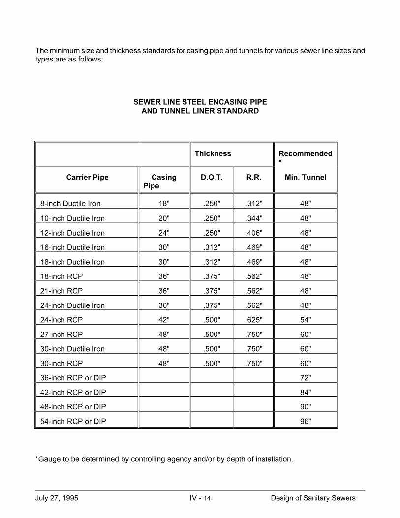
The minimum size and thickness standards for casing pipe and tunnels for various sewer line sizes and types are as follows: SEWER LINE STEEL ENCASING PIPE AND TUNNEL LINER STANDARD
Thickness
Recommended*
Carrier Pipe
Casing Pipe
D.O.T.
R.R.
Min. Tunnel
8-inch Ductile Iron
18"
.250"
.312"
48"
10-inch Ductile Iron
20"
.250"
.344"
48"
12-inch Ductile Iron
24"
.250"
.406"
48"
16-inch Ductile Iron
30"
.312"
.469"
48"
18-inch Ductile Iron
30"
.312"
.469"
48"
18-inch RCP
36"
.375"
.562"
48"
21-inch RCP
36"
.375"
.562"
48"
24-inch Ductile Iron
36"
.375"
.562"
48"
24-inch RCP
42"
.500"
.625"
54"
27-inch RCP
48"
.500"
.750"
60"
30-inch Ductile Iron
48"
.500"
.750"
60"
30-inch RCP
48"
.500"
.750"
60"
36-inch RCP or DIP
72"
42-inch RCP or DIP
84"
48-inch RCP or DIP
90"
54-inch RCP or DIP
96"
*Gauge to be determined by controlling agency and/or by depth of installation.
July 27, 1995 IV - 14 Design of Sanitary Sewers
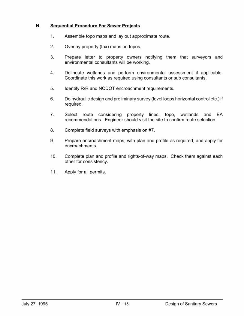
N. Sequential Procedure For Sewer Projects
1. Assemble topo maps and lay out approximate route.
2. Overlay property (tax) maps on topos.
3. Prepare letter to property owners notifying them that surveyors and environmental consultants will be working.
4. Delineate wetlands and perform environmental assessment if applicable.
Coordinate this work as required using consultants or sub consultants.
5. Identify R/R and NCDOT encroachment requirements.
6. Do hydraulic design and preliminary survey (level loops horizontal control etc.) if required.
7. Select route considering property lines, topo, wetlands and EA
recommendations. Engineer should visit the site to confirm route selection.
8. Complete field surveys with emphasis on #7.
9. Prepare encroachment maps, with plan and profile as required, and apply for encroachments.
10. Complete plan and profile and rights-of-way maps. Check them against each
other for consistency.
11. Apply for all permits.
July 27, 1995 IV - 15 Design of Sanitary Sewers