Embed Size (px)
Citation preview
34 Maritime Reporter & Engineering News
FEATURE OFFSHORE
By Stephen Gleaves, PE, ElectricalDepartment Manager, Guido Perla &
Associates, Inc.Electric ship propulsion has been
around since 1886, when Siemens deliv-ered the "Accumulator" powered, 11mlong and 2m wide vessel ELEKTRA, a30 passenger vessel equipped with a4.5kW electric propulsion motor [3].
The Russian tanker VANDAL,launched in 1903, was the first shippowered by a diesel-electric propulsionsystem, built by ASEA of Sweden, nowpart of ABB [2]. The VANDAL hadthree DC motors rated 75kW each, witheach motor turning one of three pro-peller shafts. The VANDAL was alsothe first ship to use any diesel engine aspart of its propulsion system, so it can besaid that diesel ship propulsion anddiesel-electric (DE) ship propulsionstarted the same day in history.
One of the first patents for a practicalships electric propulsion drive wasgranted in 1904 to the Italian electricalengineer Cesido Del Proposto. Hisdesign provided a method for reversingthe shaft of a diesel driven propeller.
When going in the ahead direction thepropeller was clutched directly to thediesel (or prime mover). To go astern,the clutch was disengaged, and a gener-ator on the prime mover provided elec-trical power to a motor attached to thepropeller that rotated in reverse.Although not a pure DE system, it wasmore efficient than the system installedon the VANDAL. This was the mainimpetus for using electric motors withthe early applications of diesel propul-sion, since the first diesels were notreversible, and reliable reversing gear-boxes were still waiting to be invented.
In the United States, one of the veryfirst electric propulsion systems wasinstalled on the USS HOLLAND (SS-1), a submarine built by the J.P. HollandTorpedo Boat Company of New YorkCity [1]. It used gasoline engines whileon the surface for propulsion and tocharge batteries. When submerged itused the batteries to run an electricmotor to turn the propellers. The motorserved as a shaft driven generator whenthe sub was operating on the gasengines.
The military was an early proponent ofelectric propulsion. At first, most appli-cations were in submarines, for obviousreasons. But in 1908 the Lightship LS-88 was built with DE propulsion. Thiswas followed by a General Electric (GE)steam turbine-electric drive Collier in1913, then the Battleship USS NEWMEXICO in 1918. The battleship hadtwo G.E. steam turbo-generators, nineBabcock & Wilcox boilers and four10,000 hp G.E. propulsion motors.Many more naval electric propulsionships followed.
These systems were popular with themilitary for many of the same reasonselectric propulsion is making a come-back today. No special astern mecha-nisms are required. Engine roomarrangements can be flexible. There isno long shaft alley to have to designaround. Long periods of operation atlow speeds are no problem. Multiplegenerators offer increased reliability.Full torque is available at lower speedsfor faster response and better maneuver-ing. These were all features importantto optimizing the function of a naval
combatant. The same features are appli-cable and equally beneficial to commer-cial and industrial ships.
The State of Diesel ElectricPropulsion Today
Direct Current (DC) systems were thebread and butter of electric propulsionfor decades, and still sees significant usetoday. However, the development of fre-quency converters allowed for a changein the whole concept of a ship's electri-cal system. It was now possible to use a"Power Station" concept, wherein oneset of generators, typically medium orhigh speed, could be used to power allthe ship's electrical loads, includingelectric propulsion. One of the firstlarge scale installations on a passengervessel of the power station concept wasthe retrofit of the QE2 by GEC ofBritain, wherein 9 resiliently mountedMAN B&W 9L 58/64 type mediumspeed diesels supplied power to the95.5MW propulsion plant and ship'selectrical system.
Early solid state power electronicsused in frequency converters was typi-
Electric Propulsion
It’s Time to Get Onboard
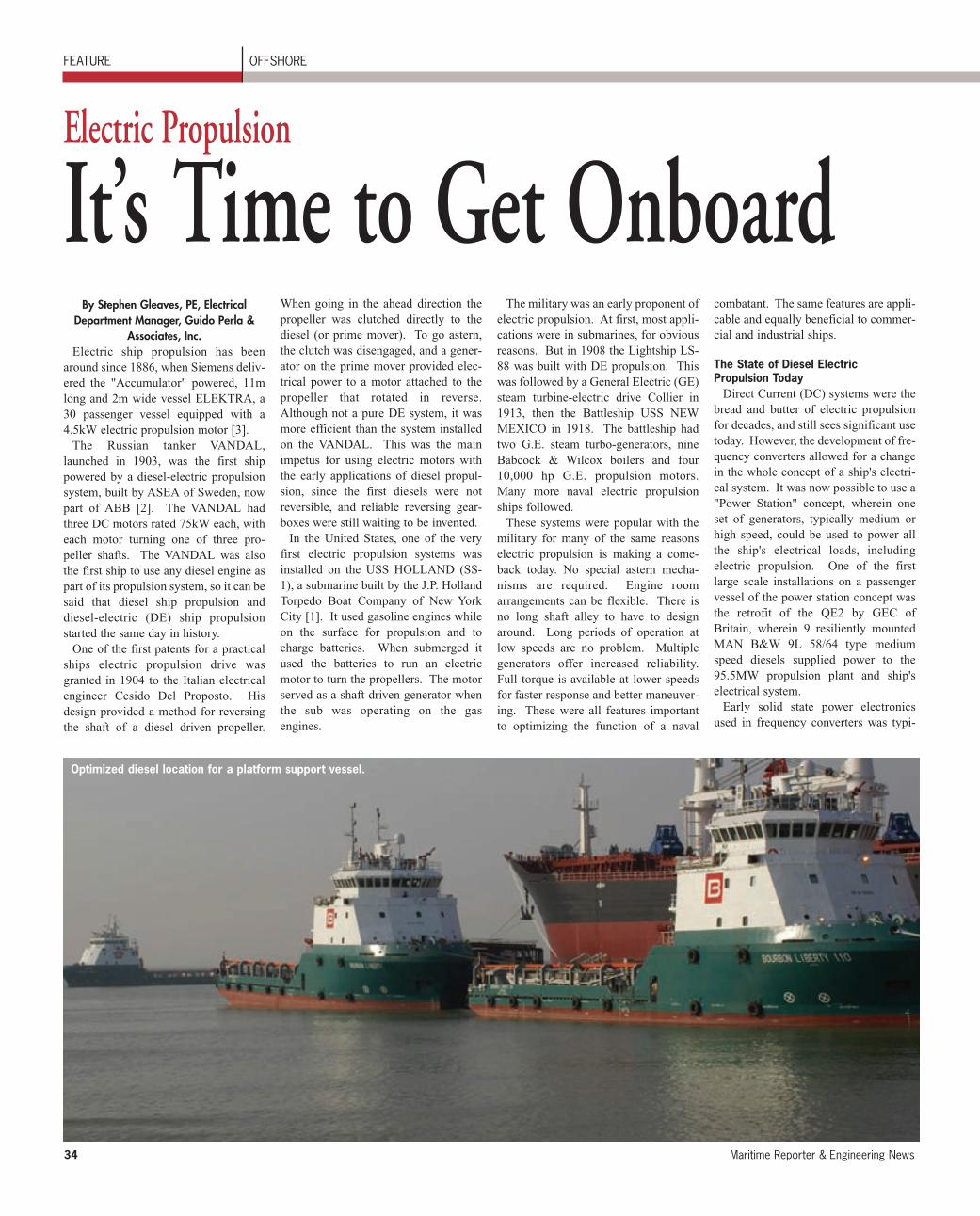
Optimized diesel location for a platform support vessel.
MR Apr. 2009 #5 (33-40).qxd 4/7/2009 8:07 PM Page 34
April 2009 www.marinelink.com 35
cally a thyristor, or Silicon ControlledRectifier (SCR). These are robustdevices capable of carrying high cur-rents, but with the somewhat tricky traitthat they can only be turned on. To turnone off, it has to be "commutated",which means that somehow the voltageat its terminals needs to be revered for ashort time to stop conduction. Oncestopped, the device can then be forwardbiased again, making it ready for thenext signal to turn it back on. Even withthis characteristic, the SCR has been thebackbone of high power requirementelectric propulsion systems, used incycloconverters, load commutatedinverters (LCI), both a type of frequen-cy converter, and in AC rectifiers, forDC systems.
SCR's are still the solid state electron-ics component of choice in really largepower applications. Cruise ships, icebreakers, specialty cargo ships (theTOTE ORCA Class RO-RO ships have19MW on each of two electric motordriven shafts), and other ships with elec-tric propulsion requirements aboveabout 5MW per shaft have had littleother choice, as there simply weren't anyother power electronics capable of han-dling either the current or voltages need-ed to support these power levels. In par-ticular, there wasn't anything thatbehaved like a transistor and that couldhandle anywhere near the desired powerlevels. Finding a way to both turn onand turn off the solid state device hasbeen the Holy Grail of power electron-ics for large drives.
Several companies attempted to pro-duce some version of a thyristor thatcould be turned off using a control sig-nal rather than commutation. ABBdeveloped a device called a GTO (GateTurn-Off thyristor). It is basically anSCR with the ability to deplete the gateregion of the semiconductor of currentcarriers, causing the device to stop con-ducting. The device has many of thebenefits of an SCR, like usable at rela-tively high voltages (~5kV), and lowconduction losses. But the device isslow, and requires substantial additionalcircuitry, in this case a snubber circuit,to work properly, making it expensiveand reducing reliability. The GTO hasseen some use in ship propulsion, most-ly in ABB designs.
In the last decade there have been sig-nificant advances in devices that trulybehave like a transistor, but can work athigh power levels. The capabilities of adevice called an IGBT (Insulated GateBipolar Transistor) have incrementallyadvanced year to year, until it is nowshowing up in systems well above2MW, challenging DC directly, and
beginning to make inroads into higherpower systems that have been thedomain of SCR based designs.
Why are transistor characteristics sucha big deal? Torque control! DC has hada long life because a DC motor candeliver full rated torque at any speed andcan change speed and direction veryquickly. Try to do that with any internal
combustion engine. SCR based variablefrequency systems come close to DCperformance, but problems start to occuras soon as speed drops below maximum.Device duty cycles become a problem,since they may be in conduction longerthan they are designed to conduct whenin low speed operation. Harmonics tendto be worse below maximum speed.
The control electronics associated withSCR systems is fairly complex in a vari-able speed system.
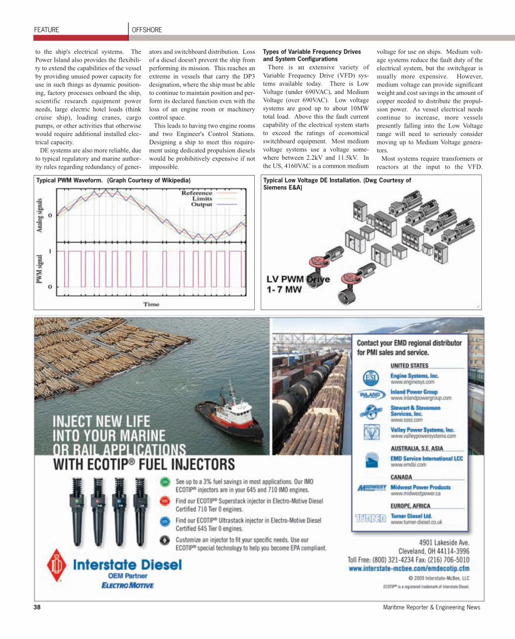
What a transistor based system allowsis a mode of operation for controllingthe speed of a motor called PWM (PulseWidth Modulation). This type of speedcontrol creates a "virtual" motor operat-ing frequency by first creating a high
MR Apr. 2009 #5 (33-40).qxd 4/7/2009 2:39 PM Page 35
36 Maritime Reporter & Engineering News
frequency square wave output from thevariable speed drive, typically 2000 Hzto 5000 Hz, and then modulating thewidth of each square pulse of that high-er frequency to create a torque current inthe motor, causing it to rotate it at anyspeed desired, including zero rpm. Themodulation signal can be controlled tocause an AC motor to behave virtuallyidentically to a DC motor. Modulatingthe width of a square wave (effectivelywhat is occurring in the control circuit-ry) is fairly simple, making a PWMdrive reliable and comparatively inex-pensive. The other really nice thingabout PWM is it works well with induc-tion motors. AC induction motors areextremely reliable, inexpensive com-pared to DC motors of the same horse-power rating, and very low maintenance.
To work well this technique requires adevice that can quickly turn on and off.That is one of the features of a transistor.But transistors have their shortcomings,like higher internal losses, limited cur-rent carrying capability, and limitedvoltage level. These limitations thathave been largely overcome in the lastfew years. However, this has notstopped development of competingtechnologies. ABB and Siemens haveboth been developing a device called anIGCT (Integrated Gate CommutatedThyristor), which they claim combines
the best features of an SCR and anIGBT. It has fast speed of operation,very low losses in conduction, and isusable at voltages typically higher thanthose at which an IBGT can be used.
Merits of AC vs DC DrivesIf the characteristics of DC are so
desirable, why change? DC has a goodtrack record and is very reliable. But itisn't perfect, and there are other forces atwork driving manufacturers away fromlarge DC applications.
A single DC motor is limited to about8MW maximum output. This mostly isdue to limitations of the commutator andbrushes in a DC motor. The brusheshave current density limitations, whilethe commutator segments have voltagelimitations. DC motors are also com-plex devices, expensive to build in largesizes, and heavy. Although electricallysimple overall, it is still something of anart to get every element of DC motorinstallation, like brush alignment, brushchemistry, field alignment, and commu-tator film development, to come togeth-er just right and all at the same time foroptimum operation of the motor. DCmotors also have much higher mainte-nance requirements than either AC syn-chronous or induction motors. There arefewer manufacturers of large DCmotors, fewer service centers, and fewer
operating engineers with any real expe-rience or understanding of the nuancesof maintaining a DC motor in good con-dition.
Add to this that economic forces aredriving manufacturers of DC drivesaway from the marine market, and itstarts to become clear why most manu-facturers of marine propulsion drives arepursuing Variable Frequency Drives(VFD) so intensively over DC. It isexpensive to build both motors anddrives to the special rules and standardsthat the maritime authorities require.Original Equipment Manufacturers(OEM's) are less inclined to produce andstock as standard products anything thatdoesn't sell in large quantities. Thisargument is not so strong in regards tothe motors, particularly if it is a choicebetween a large synchronous motor or alarge DC motor. Both are special con-struction. But in drives it is a leadingfactor in the decision of such companiesas Siemens to no longer produce an Off-the-Shelf marine rated DC propulsiondrive. These top tier OEM manufactur-ers are putting their effort into VFDdevelopment and slowly letting go ofDC technology.
There are still third party integratorsoperating in niche markets where DCcan fill the bill both technically and eco-nomically. Companies like EPD
(Electronic Power Design, Inc.) ofHouston, Texas, are supplying signifi-cant quantities of marine propulsion andplatform motors and controls in a DCformat. Using the ubiquitous GE 752motor and marinizing OEM DC drivesfor the purpose, they are supplyingpropulsion systems for PSV's, jack-uprigs, and other oil field applications thatare familiar with and still demand thistype of system.
Benefits of Diesel ElectricDiesel Electric propulsion has signifi-
cant advantages in many areas whencompared to other propulsion systems.Since diesel has replaced just about allother propulsion systems exceptnuclear/steam on some Navy aircraftcarriers and submarines, this compari-son will limit itself to equivalent dieseldirect mechanical drive propulsion sys-tems.
A diesel-only system requires somekind of mechanical linkage from thediesel output coupling to the propeller.This necessitates putting the dieselinline with some set of componentsmaking up that linkage, typically areduction gear and shaft. The reductiongear is used to match the diesel speed tothe required propeller speed, which typ-ically is lower than the engine rpm forbest efficiency of operation. The reduc-
FEATURE OFFSHORE
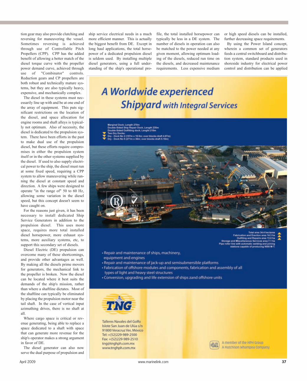
Typical 12 and 24 Pulse Configurations.(Diagram Courtesy of Siemens E&A)
Typical Medium Voltage High Power DE Installation.(Diagram Courtesy of Siemens E&A)
Integrated Gate Commutated Thyristor. (Photo Courtesy of ABB)
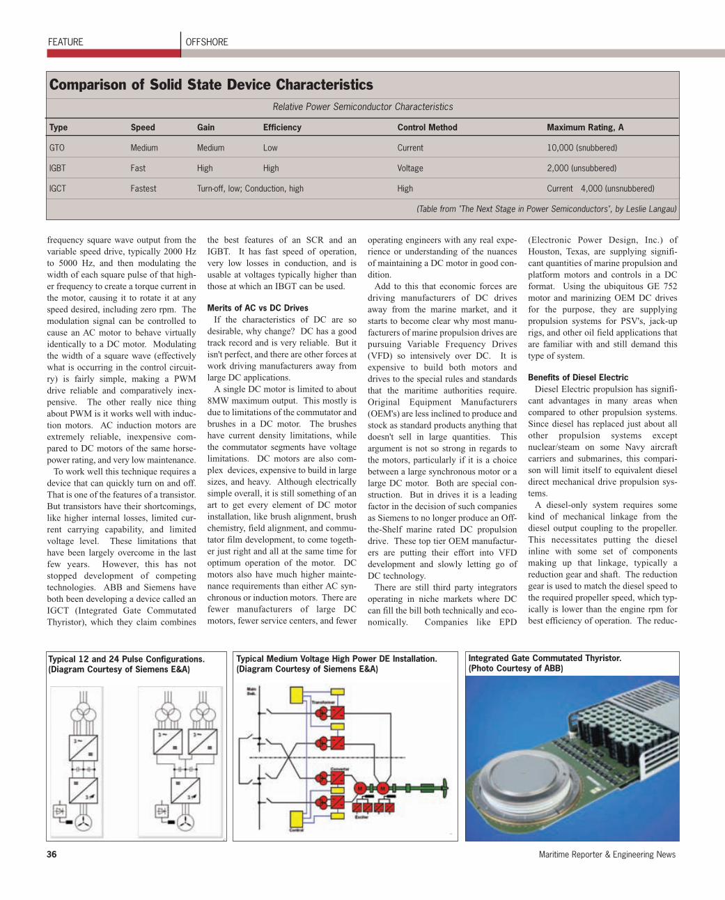
Comparison of Solid State Device CharacteristicsRelative Power Semiconductor Characteristics
Type Speed Gain Efficiency Control Method Maximum Rating, A
GTO Medium Medium Low Current 10,000 (snubbered)
IGBT Fast High High Voltage 2,000 (unsubbered)
IGCT Fastest Turn-off, low; Conduction, high High Current 4,000 (unsnubbered)
(Table from "The Next Stage in Power Semiconductors", by Leslie Langau)
MR Apr. 2009 #5 (33-40).qxd 4/7/2009 2:39 PM Page 36
April 2009 www.marinelink.com 37
tion gear may also provide clutching andreversing for maneuvering the vessel.Sometimes reversing is achievedthrough use of Controllable PitchPropellers (CPP). CPP has the addedbenefit of allowing a better match of thediesel torque curve with the propellerpower demand curve, achieved throughuse of "Combinator" controls.Reduction gears and CP propellers areboth robust and technically mature sys-tems, but they are also typically heavy,expensive, and mechanically complex.
The diesel in these systems must nec-essarily line up with and be at one end ofthe array of equipment. This puts sig-nificant restrictions on the location ofthe diesel, and space allocation forengine rooms and shaft alleys is typical-ly not optimum. Also of necessity, thediesel is dedicated to the propulsion sys-tem. There have been efforts in the pastto make dual use of the propulsiondiesel, but these efforts require compro-mises in either the propulsion systemitself or in the other systems supplied bythe diesel. If used to also supply electri-cal power to the ship, the diesel must runat some fixed speed, requiring a CPPsystem to allow maneuvering while run-ning the diesel at constant speed anddirection. A few ships were designed tooperate "in the range of" 50 to 60 Hz,allowing some variation in the dieselspeed, but this concept doesn't seem tohave caught on.
For the reasons just given, it has beennecessary to install dedicated ShipService Generators in addition to thepropulsion diesel. This uses morespace, requires more total installeddiesel horsepower, more exhaust sys-tems, more auxiliary systems, etc, tosupport this secondary set of diesels.
Diesel Electric (DE) propulsion canovercome many of these shortcomings,and provide other advantages as well.By making all the diesels prime moversfor generators, the mechanical link tothe propeller is broken. Now the dieselcan be located where it best suits thedemands of the ship's mission, ratherthan where a shaftline dictates. Most ofthe shaftline can typically be eliminatedby placing the propulsion motor near thetail shaft. In the case of vertical inputazimuthing drives, there is no shaft atall.
Where cargo space is critical or rev-enue generating, being able to replace aspace dedicated to a shaft with spacethat can generate more revenue for theship's operator makes a strong argumentin favor of DE.
The diesel generator can also nowserve the dual purpose of propulsion and
ship service electrical needs in a muchmore efficient manner. This is actuallythe biggest benefit from DE. Except inlong haul applications, the total horse-power of a dedicated propulsion dieselis seldom used. By installing multiplediesel generators, using a full under-standing of the ship's operational pro-
file, the total installed horsepower cantypically be less in a DE system. Thenumber of diesels in operation can alsobe matched to the power needed at anygiven moment, allowing optimum load-ing of the diesels, reduced run time onthe diesels, and decreased maintenancerequirements. Less expensive medium
or high speed diesels can be installed,further decreasing space requirements.
By using the Power Island concept,wherein a common set of generatorsfeeds a central switchboard and distribu-tion system, standard products used inshoreside industry for electrical powercontrol and distribution can be applied
MR Apr. 2009 #5 (33-40).qxd 4/7/2009 2:40 PM Page 37
38 Maritime Reporter & Engineering News
to the ship's electrical systems. ThePower Island also provides the flexibili-ty to extend the capabilities of the vesselby providing unused power capacity foruse in such things as dynamic position-ing, factory processes onboard the ship,scientific research equipment powerneeds, large electric hotel loads (thinkcruise ship), loading cranes, cargopumps, or other activities that otherwisewould require additional installed elec-trical capacity.
DE systems are also more reliable, dueto typical regulatory and marine author-ity rules regarding redundancy of gener-
ators and switchboard distribution. Lossof a diesel doesn't prevent the ship fromperforming its mission. This reaches anextreme in vessels that carry the DP3designation, where the ship must be ableto continue to maintain position and per-form its declared function even with theloss of an engine room or machinerycontrol space.
This leads to having two engine roomsand two Engineer's Control Stations.Designing a ship to meet this require-ment using dedicated propulsion dieselswould be prohibitively expensive if notimpossible.
Types of Variable Frequency Drivesand System Configurations
There is an extensive variety ofVariable Frequency Drive (VFD) sys-tems available today. There is LowVoltage (under 690VAC), and MediumVoltage (over 690VAC). Low voltagesystems are good up to about 10MWtotal load. Above this the fault currentcapability of the electrical system startsto exceed the ratings of economicalswitchboard equipment. Most mediumvoltage systems use a voltage some-where between 2.2kV and 11.5kV. Inthe US, 4160VAC is a common medium
voltage for use on ships. Medium volt-age systems reduce the fault duty of theelectrical system, but the switchgear isusually more expensive. However,medium voltage can provide significantweight and cost savings in the amount ofcopper needed to distribute the propul-sion power. As vessel electrical needscontinue to increase, more vesselspresently falling into the Low Voltagerange will need to seriously considermoving up to Medium Voltage genera-tors.
Most systems require transformers orreactors at the input to the VFD.
FEATURE OFFSHORE
Typical PWM Waveform. (Graph Courtesy of Wikipedia) Typical Low Voltage DE Installation. (Dwg Courtesy ofSiemens E&A)
MR Apr. 2009 #5 (33-40).qxd 4/7/2009 2:40 PM Page 38
April 2009 www.marinelink.com 39
IRGImmediate Response Group, LLC
www.immediateresponsegroup.comCall Now Toll-Free (888) 900-5052
IMMEDIATE RESPONSE GROUPWorld Class Personal & Asset ProtectionIMMEDIATE RESPONSE GROUPWorld Class Personal & Asset Protection
OUR SERVICES INCLUDE• CORPORATE SECURITY
• EXECUTIVE, PERSONAL & TRAVEL PROTECTION
• RANSOME RESPONSE & NEGOTIATION
• SECURITY/FORCE PROTECTION
• MARITIME SECURITY/PROTECTION
• DISASTER/EMERGENCY RESPONSE
• ASSET RECOVERY
• K9 NARCOTICS & EXPLOSIVE DETECTION
• BUSINESS CONTINGENCY PLANNING & CONSULTING
• THREAT & VULNERABILITY ASSESSMENTS
Sometimes this is to match voltageneeds of a specific manufacturer's VFD.Sometimes it is to create a "multiplepulse" system, related to reducing theharmonics developed in the VFD andfed back into the ships mains. There aresome new system designs that reduce oreliminate the need for transformers,reducing cost and weight.
In most cases, the variations indesigns are related to an attempt toreduce or eliminate harmonics.Harmonics are an electrical byproductof a typical VFD. Harmonics are anydeviation from the pure voltage or cur-rent sine wave you see in old Sci-Fimovies on those little green oscillo-scope screens. Harmonics are the"Achilles heel" of DE propulsion. Theycan create havoc with other electricalequipment, especially electronics, butcan even cause problems with hardwarelike motors if harmonic levels aresevere enough.
In the past, harmonics were dealt withby installing inductive and capacitivefilters that would reduce the level ofharmonics on the system. Since har-monics usually consist of multiple fre-quencies, a different filter set is neededfor each frequency. This is where one
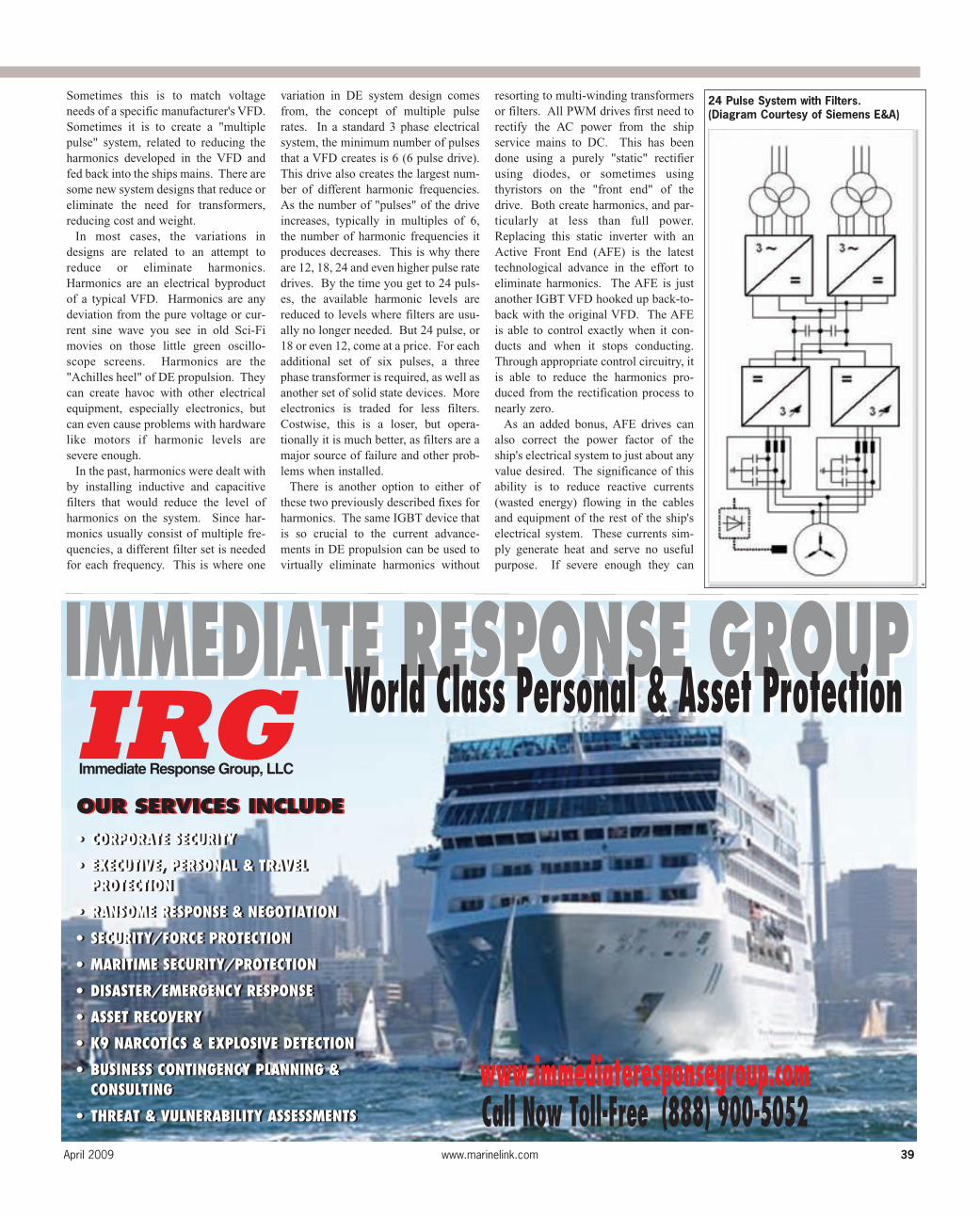
variation in DE system design comesfrom, the concept of multiple pulserates. In a standard 3 phase electricalsystem, the minimum number of pulsesthat a VFD creates is 6 (6 pulse drive).This drive also creates the largest num-ber of different harmonic frequencies.As the number of "pulses" of the driveincreases, typically in multiples of 6,the number of harmonic frequencies itproduces decreases. This is why thereare 12, 18, 24 and even higher pulse ratedrives. By the time you get to 24 puls-es, the available harmonic levels arereduced to levels where filters are usu-ally no longer needed. But 24 pulse, or18 or even 12, come at a price. For eachadditional set of six pulses, a threephase transformer is required, as well asanother set of solid state devices. Moreelectronics is traded for less filters.Costwise, this is a loser, but opera-tionally it is much better, as filters are amajor source of failure and other prob-lems when installed.
There is another option to either ofthese two previously described fixes forharmonics. The same IGBT device thatis so crucial to the current advance-ments in DE propulsion can be used tovirtually eliminate harmonics without
resorting to multi-winding transformersor filters. All PWM drives first need torectify the AC power from the shipservice mains to DC. This has beendone using a purely "static" rectifierusing diodes, or sometimes usingthyristors on the "front end" of thedrive. Both create harmonics, and par-ticularly at less than full power.Replacing this static inverter with anActive Front End (AFE) is the latesttechnological advance in the effort toeliminate harmonics. The AFE is justanother IGBT VFD hooked up back-to-back with the original VFD. The AFEis able to control exactly when it con-ducts and when it stops conducting.Through appropriate control circuitry, itis able to reduce the harmonics pro-duced from the rectification process tonearly zero.
As an added bonus, AFE drives canalso correct the power factor of theship's electrical system to just about anyvalue desired. The significance of thisability is to reduce reactive currents(wasted energy) flowing in the cablesand equipment of the rest of the ship'selectrical system. These currents sim-ply generate heat and serve no usefulpurpose. If severe enough they can
24 Pulse System with Filters.(Diagram Courtesy of Siemens E&A)
MR Apr. 2009 #5 (33-40).qxd 4/7/2009 2:41 PM Page 39
damage electrical equipment, includ-ing the generators. This is why it isimportant to have kVAR meters onswitchboards that feed large VFDloads or that have large generatorsoperating in parallel.
Although AFE drives are moreexpensive than a static front endVFD, it becomes possible to simplifythe rest of the propulsion power sys-tem. Fewer or smaller transformersare needed, and 6 pulse drives nolonger need filters. When first intro-duced in the late 1990's, it wasthought AFE would replace every-thing else, but complexity of design,costs, power limitations, and someinitially high failure rates kept themfrom achieving their potential. Thestate of the art has progressed, how-ever, and several OEM's are seeinggood results with their current gener-ation of AFE drives.
Another DE method that has seensome application are fixed frequencyelectric propulsion systems. The con-cept here is to eliminate the VFD andthe various problems associated withit, while retaining the advantages ofDE. Propulsion motors are run at fullspeed all the time, while requiredchanges in power and direction areachieved through CP propellers.Sounds good, and for long voyages itcould be a viable system. In anyother application it has a number of
problems. When the propeller is notat full power, significant power iswasted overcoming water resistancein simply spinning the propeller athigh speed. In a geared system prob-lems arise when the shaft bearingsand gears are hovering at some neu-tral point where they are neither real-ly pushing nor pulling. Gear chatterand bearing seals suffer from highwear. This is an extremely inefficientsystem with high maintenancerequirements. The need for CPP andin all probability a CPP hydraulicsystem adds additional complexity, ahigh loss auxiliary system, and thepotential for hydraulic leaks.Additionally, most systems wouldrequire some kind of reduced voltagestarter for the large motors, which,although not as expensive as a VFD,is almost there, so why not just go thesmall extra step and get the full bene-fits that a good DE design can pro-vide? As ships become more expen-sive, their mission capabilitiesbecome more complex in order toallow more flexibility and thereforecreate more potential for findingprofitable work. Diesel electricpropulsion and a fully DE ship pro-vide the most flexible propulsion andpower platform available.Environmental regulations, cost offuel, mission support criteria,increased power needs of new ves-
sels, declining costs of VariableFrequency Drives due to technologi-cal advances, and the eventual gener-al acceptance of electric propulsionby the industry will result in DE shipsbecoming the norm rather than theexception. There are several exam-ples of this already occurring inapplications that just a few years agowould have never considered DEpropulsion to be a viable option. TheTOTE ORCA Class RoRo is a primeexample. The Navy is moving to AllElectric ships for their new designs,in large part because the missionloads have tremendous electricalrequirements, and it therefore makessense to make every aspect of powerdelivery in the vessel electrical innature. The rest of the marine com-munity will shortly follow suit formuch the same reasons.
Bibliography:
1. . . .Captain John A. Culver, USNR (RET), ElectricDrive Propulsion for Ships, An HistoricalSummary, Trafford Publishing.
2. . . . . . . . . . . .Norwegian Society of Engineers, 2ndInternational Diesel Electric Propulsion, 95 Yearsof Diesel-Electric Propulsion Form a MekeshiftSolution to a Modern Propulsion System
3. . . . . .Siemens Energy & Automation, Mr. ThomasOrberger
FEATURE OFFSHORE
Fairhaven, MA: 508-990-0072 Newcastle, ME: 207-563-3210 www.farrellandnorton.com
Pictured: 265’ Class LiftboatSOLAS, ABS, USCG
‘Superior Respect’ Delivered by BOCONCO Inc., April 2009
Specializing in design and engineering of commercial vessels
Liftboats Tugboats
Pushboats Oil Supply Vessels
Research Vessels Crewboats
Farrell and Norton Naval Architects
40 Maritime Reporter & Engineering News
MR Apr. 2009 #5 (33-40).qxd 4/8/2009 3:41 PM Page 40