Embed Size (px)
Citation preview

Issue 002 Section 4
Section Index (i)
Copy No.y,
4. COAL FIRING
4.1 The Combustion Process
4.2 Design Procedures for Coal-fired Combustors
4.2.1 Scope of Section 44.2.2 Choice of coal feeding method
4.3 In-bed Feeding of Crushed Coal
4.3.1 Calculation of combustion in the bed and freeboardwithout fines recycle
4.3.1.1 Bed combustion4.3.1.2 Freeboard combustion4.3.1.3 Allowance for coals of different reactivity4.3.1.4 Combustion of low grade, high ash coals
4.3.2 Freeboard design4.3.2.1 Freeboard treated as a unit4.3.2.2 Stepwise calculation of freeboard combustion
4.4 Overbed Feeding
4.4.1 General considerations4.4.2 Overbed feeding techniques4.4.3 Estimation of combustion efficiency
4.4.3.1 Combustion efficiency correlation 14.4.3.2 Combustion efficiency correlation 24.4.3.3 Choice of correlation
4.5 Methods of Reducing Unburnt Carbon Loss
4.5.1 Freeboard baffles4.5.2 Combustion of elutriated carbon in a separate bed
4.5.2.1 Carbon burn-up cell design with in-bed feeding
4.5.3 Refiring of fines to the main bed4.5.3.1 Combustion loss estimation for fines recycle with
in-bed feeding
4.5.4 Reduction in fines content of feed4.5.5 Operation at higher temperature or higher excess air
levels
4.6 Assessment of Coals for Suitability in FluidisedCombustors

Issue 002 Section 4
Section Index (ii)
Copy No.
4.7 Effect of Coal Characteristics on Combustor Design andOperation
4.7.1 General effects4.7.2 Moisture content4.7.3 Swelling number4.7.4 Coal rank4.7.5 Ash content
4.7.5.1 Effect of ash content on combustion4.7.5.2 Effect of ash content on distributor design4.7.5.3 Coal ash as a bed material
4.8 Estimation of the Initial Ash Size Distribution Producedby the Combustion of Coal
4.9 Conversion of Existing Equipment to Coal Firing
4.10 Turndown
4.11 Firing of Coal/Liquid Mixtures
4.12 Example Calculation
4.12.1 Calculation basis4.12.2 Design and Operating Data4.12.3 Calculation 1 - no recycle4.12.4 Calculation 2 - recycle of 80% of the primary.cyclone
catch
4.13 References

Issue 002 Section 4
Page 1 of 96
Copy No. I
4. COAL FIRING
4.1 The Combustion Process
A coal-fired fluidised bed combustor contains burning coal
particles Chat are dispersed uniformly throughout a fluidised bed of hot
inert particles. The coal is fed at one or more points and the action of
the fluidising process disperses it throughout the bed. Two feeding
methods can be used; they are termed in-bed feeding and over bed feeding.
The in-bed feeding method consists of the injection of the coal
into the bed at points situated near the base of the bed and arranged
evenly over the bed cross-section. This method is suitable for feeding
crushed coal with a top size of up to 6 mm (0.25 in.). Usually the coal is
conveyed pneumatically, using air, through the injection tubes which pass
into the bed either vertically upwards through the air distribution plate
or horizontally through the combustion side walls. Screw feeders can also
be used if the injection tubes are horizontal.
The above bed feeding method consists in feeding the coal to the
surface of the bed. This method is more suitable for use with uncrushed
coals. The coal can be simply dropped onto the bed surface through one or
more steeply inclined chutes passing through the freeboard side walls or it
can be thrown onto the bed surface by a device such as a spreader stoker.
The bed solids may be an inert material like sand,j orfalumina, or---
limestone if sulphur retention is required. It is also possible that part
of the coal ash formed on combustion can provide a suitable bed material.
The mineral content of cbal is present in two forms known as "inherent" ash
and "discrete" ash. Inherent ash takes the form of widely-dispersed small
particles imbedded in the combustible part of the coal substance. Discrete
ash is lumps of mainly mineral matter of a size comparable with that of the
rest of the coal particles. On combustion, the inherent ash usually
produces particles that are so small that they are rapidly elutriated ftom
the bed. On the other hand, the discrete ash after combustion may leave

Issue 002 Section 4
Page 2 of 96
Copy No. g
particles that are of a suitable size and strength to form the bed solids.
The coal fed to the bed is heated rapidly by radiation and
conduction, and moisture in the coal is evaporated. At a particle
temperature of between 230' and 350°C, (440'- 660'F), decomposition of the
coal substance starts, with evolution of carbon monoxide, hydrogen, gaseous
hydrocarbons and tars. This stage is referred to as devolatilisation, and
the substances evolved are known as coal volatiles. The devolatilisation
stage is longer than the initial stage (4.1) and when it is complete, the
particle is at a temperature approaching the bed temperature. There then
follows a further rapid rise to the particle equilibrium combustion
temperature which may be as much as 215°C (390'F) above the mean bed
temperature (4.1, 4.2, 4.38).
The time required for the initial rapid heating stage is a
function of the particle diameter and is quite short. A duration of less
than 3 seconds for particles less than 8 mm (0.3 in.) in diameter has been
quoted (4.1). When considering the spacing of coal feed points, the
thermal load resulting locally in the bed from this rapid heating stage may
be important, especially when, firing high-moisture, low calorific value,
fine coals. It should be borne in mind that solids mixing times are of the
order of 5 - 10 seconds, and it is desirable to maintain as uniform a bed
temperature as possible.
Devolatilisation times are typically ten or twenty times as long
as the initial heating times, but vary greatly with coal type, as does the
quantity of volatiles involved. The devolatilised, or "char", particles
remain burning in the bed until they have become so reduced in size that
they are elutriated. The time needed for complete char burn-out is longer
still than that for devolatilisation and may be up to 2000 seconds for
large particles.
It is important for both economic and environmental reasons that'
the combustion efficiency of a coal-fired combustor should be high. For
maximum efficiency, both the volatiles and the fixed carbon (char)

Issue 002 Section 4
Page 3 of 96
Copy No.'_
components of the coal must be burned as completely as possible. The rate
of combustion of the volatiles is controlled mainly by the rate at which
they mix with oxygen, but rapid chilling may quench the reaction even if
oxygen is present. For example, when crushed coal (3 mm (0.12 in.) top
size) is being fired, the time needed for devolatilisation is only 10 to 30
seconds at a bed temperature of 875°C (1610°F), and much of this occurs
within the first five seconds (from the finest fraction of the coal) (4.3).
In these circumstances, therefore, the combustion of the volatiles makes
heavy demands on the supply of oxygen in the vicinity of the coal feed
points, and if insufficient oxygen is available for their complete
combustion within the bed, combustion will continue in the gas mixing zone
above the bed giving rise to a luminous flame which may be smoky and
contribute to a low combustion efficiency. Similar considerations would
apply to the combustion of the fines content of uncrushed coals. To ensure
that sufficient oxygen is available it is suggested, therefore, that the
bed area served by a single feed point should not exceed 0.6 m2 (6 ft ) for
in-bed feeding and 4.0 m (43 ft ) for above bed feeding using a drop tube
feeder or twice that area using a spreader type feeder.
The char remains in, the bed for long enough to be transported
well away from the feed points, and burns away eventually to a size at
which it can be elutriated from the bed. The elutriation of solid
carbonaceous particles is usually the biggest cause of combustion
inefficiency in coal fired fluidised bed combustors. When firing high ash
coals, or when using high sorbent feed rates (see Section 11), significant
carbon losses can also occur in the bed withdrawal stream. The carbon loss
resulting from elutriation of unburnt carbon depends on many factors: the
proportion of fine particles in the coal feed; the susceptibility of the
coal to breakage due to heating and attrition (4.4, 4.5); the coal
reactivity, excess air and bed temperature (which jointly determine the
concentration of carbon in the bed and hence the elutriation rate - (see
Section 9)); and the fluidising velocity.
Further combustion of elutriated carbon occurs in the freeboard
and factors controlling this include excess air, freeboard gas mixing,

Issue 002 Section 4
Page 4 of 96
Copy No., )
freeboard dimensions, and gas residence time and temperature in the
freeboard. The region of the freeboard immediately above the bed surface
is termed the "splash zone" because both inert bed particles and burning
char particles are continuously.being ejected into it and falling back to
the bed. The splash zone has no sharp upper boundary; with increasing
distance from the bed surface the solids concentration falls and eventually
reaches a value corresponding to steady state elutriation conditions. The
combustion contribution of the freeboard, and especially of the splash
zone, is important and to allow for it a freeboard height of at least 1 m
(3.3 ft) is recommended.
The influence of different variables on combustion rates depends
on the combustion regime, i.e. whether the rate-limiting mechanism is the
diffusion of oxygen to the particle surface, or the chemical reaction
between oxygen and carbon at the external and internal surfaces of the
particle (4.6). Diffusion control, which is more likely to occur when
temperatures are high and particle sizes large, shows only a small
dependence of rate upon temperature and does not vary with coal type.
Chemical rate control, however, is strongly temperature dependent and
varies markedly with coal type, low rank (high-volatile) coals being much
more reactive than high rank (low-volatile) coals. The combustion of coal
particles in fluidised beds at atmospheric pressure has been shown to have
a component of chemical rate control, even at temperatures as high as
1000°C (1830°F) (4.3, 4.38) and the same probably applies in the freeboard
zone (4.7).
Mineral matter closely associated with a burning particle of
coal, such as inherent ash, can acquire a temperature roughly equal to that
of the burning particle. Since burning particle temperatures may exceed
significantly the surrounding bed temperature, and as it is imperative that
the ash sintering temperature is not exceeded either in the bed or in the
freeboard, the mean bed and freeboard temperatures should therefore not
exceed a temperature '220°C (400°F) below the ash sintering temperatures.
For most coals this imposes an upper temperature of about 900 - 950°C

Issue 002 Section 4
Page 5 of 96
Copy No.
(1650 - 1750°F). A test procedure for the determination of ash sintering
temperature is described in Section 17.
4.2 Design Procedures for Coal-Fired Combustors
4.2.1 Scope of Section 4
The general procedure for the design of a fluidised bed combustor
is outlined in Section 3 and the main purpose of Section 4 is to describe
methods for predicting the combustion efficiency during the coal firing of
fluidised combustors operating at atmospheric pressure, based on experience
gained on experimental and commercial combustors. Knowledge of behaviour
during combustion at elevated pressures is considered in Section 8. The
variations in both the applications of coal firing and the properties of
the coals burnt are considerable, however, so some discussion of the
efforts of such variations on the combustor design is included.
The methods recommended for estimating the combustion efficiency
of a coal-fired fluidised bed combustor will depend on the coal feeding
method adopted. For in-bed feeding a stepwise mathematical procedure is
described in Section 4.3. The calculation of the proportions of the heat
of combustion released in the bed and in the freeboard is described, and as
part of the heat released in the freeboard is transferred back to the bed,
instructions are given for calculating this transfer and for locating any
freeboard cooling surfaces. A worked example using the procedure is given
in Section 4.12. For above bed feeding an empirically based correlation
for the combustion efficiency of the bed and freeboard together is
described in Section 4.4 along with a summary of current experience of over
bed firing.
For both feeding methods Section 4.5 lists ways of reducing the
unburnt carbon loss, should this be unacceptably high. The recycle of
fines is one commonlyiused method. For in-bed feeding the modifications to
the calculation procedures of Section 4.3 necessary to take account of
fines recycle are given and, also for in-bed feeding, a calculation

Issue 002 Section 4
Page 6 of 96
Copy Noy.* J
procedure for the design of a separate carbon burn-up bed is described.
Section 4.7 includes notes on the probable effects of coal
characteristics on combustor design and operation and also a discussion of
ash behaviour in the bed and ways of predicting the resistance of coal ash
to abrasion and the estimation of the ash size distribution formed on
combustion of coal.
Advice is given in Section 4.9 regarding the conversion of
existing equipment to coal-fired fluidised bed combustion. A brief
discussion of the considerations relating to the combustion of coal/liquid
mixtures is included in Section 4;11.
A number of computational aids is available. A microcomputer
program "FBC Design" has been written in BASIC for the preliminary
estimation of combustor size for given operating conditions and fuel
properties (4.39). The in-bed feeding calculation procedures have been
programmed for a main frame computer using the PL1 language; the program
is described in reference (4.8). A suite of programs has been written for
a microcomputer for estimating the performance of an industrial boiler
under given operating conditions when using the above bed feeding method
and the bed expansion method for turndown (4.40, 4.41, 4.42).
It should be noted that the calculation procedures given in this
section have been derived mainly from work on the combustion of a number of
low rank bituminous coals, with some limited experience of high rank and
sub-bituminous coals. Because of this, and because coals of similar
composition may vary in their resistance to thermal shock and mechanical
attrition in the bed, the accuracy of desigh predictions is likely to be
improved by conducting experimental tests on the fuel to be used. A
description of test facilities available for this purpose is given in
Section 17 of this Manual.

Issue 002 Section 4
Page 7 of 96
Copy No.'
4.2.2 Choice of coal feeding method
The choice of a coal feeding method will depend on the
requirements of the application and on the coal properties. It is not
possible to suggest hard and fast rules but some indications as to the
suitability of the two feeding methods are given in Table 4.1.
The in-bed feeding method was developed originally for the
combustion of unwashed coals in power generation applications. Since much
of the mineral matter in unwashed coals is present as discrete ash of a
size similar to that of the combustible coal it was necessary to crush the
coal so that the ash particles formed on combustion would be sized
correctly to act as the bed solids. The overbed feeding method was
developed as a simpler alternative for use in industrial boiler
applications. It is the cheaper method as fewer feed points are needed and
no crushing is required and has been used successfully for feeding washed
graded coals. In such coals most of the mineral matter is present as
inherent ash. As a result almost all the ash formed during combustion is
elutriated and a refractory material such as sand has to be provided and
added periodically to maintain the bed. Even when firing washed coals
there is a gradual accumulation of oversize ash in the bed, and most
fluidised bed fired industrial boilers and furnaces incorporate
bed-cleaning devices, in which a small stream of bed material is removed,
classified and the material freed from large particles is returned to the
bed. See Section 15.
The flat plate type of air distributor with stand pipe air
nozzles (see Section 15) is normally used with both coal feeding methods.
However, it becomes increasingly difficult with the flat plate type to
clean the bed effectively as the ash content of coals fed by the overbed
method is increased. Recent experience (4.43) has shown that the use of a
flat distributor plate with directed air nozzles to sweep oversize
particles to ash removal ports will enable coals with ash contents up to
25% to be handled. The overbed firing of coals with ash contents over 25%
will probably require the use of the more specialised types of distributors

Issue 002 Section 4
Page 8 of 96
Copy No.
Table 4.1
Indications for Choice of Coal Feeding Method
Air Distributor: Flat plate type
with stand pipe nozzles and
few ash ports in plate
In-bed feeding indicated if - Above bed feeding indicated if -
Scale moderate to large, e.g. Scale medium to small e.g.power generation, bulk steam, industrial boilers <50 MW, firewater tube boilers tube boilers, steam or hot water
Combustion efficiency required Combustion efficiency: 94-97%high. >97% acceptable
Fuel: crushed, unwashed coals. Fuel: washed, graded coal,Coals with high fines content. singles or smalls. Top size 25 orTop size 6 mm (114 in.) 50 mm (1 or 2 in.)
Cost of crushing economic Cost of crushing uneconomic
Fuel ash content <15%. Higherash contents can be handled ifcoal top size is limited. SeeFigure 4.12.
High sulphur retention needed, Sulphur retention not needed or90% + moderate retention
Fan power costs less critical Fan power costs critical toapplication economics
Deep beds 0.5-1 m (20-40 in.) Shallow beds 0.15-0.5 mstatic (6-20 in.) static
Bed material: ash (or sorbent for Bed material: sand (or sorbentsulphur retention) for sulphur retention)
Bed solids removal required Ash mostly elutriated;intermittent bed cleaningrequired

Issue 002 Section 4
Page 9 of 96
Copy No.\ )_
Table 4.1 (continued)
Indications for Choice of Coal Feeding Method
Novel designs of distributor
available for handling high ash coals
In-bed feeding indicated if - Above bed feeding indicated if -
Air distributor: Flat plate typewith directed stand pipe nozzles.Ash ports in plate
Fuel ash 15-25%.Bed cleaning continuous
Air distributor: Recirculating bed typeor spouted bed type with central ashofftake system
Fuel ash up to 80%Ash offtake continuous
Issue 002 Section 4
Page 10 of 96
Copy No.; l
that are available for the combustion of low grade fuels. See Sections 7
and 15.
The ash content of the coal may affect the design of other
combustor components besides its effects on distributor and coal feeder
design. It is recommended that Section 4.7, which contains a discussion of
the effects of various coal properties on combustion efficiency and
combustor design, should be consulted at the outset of any design. It
should also be noted that while a fluidised bed combustor can be designed
to burn almost any fuel efficiently, any individual combustor may not
attain its rated output if fed with a fuel that differs significantly from
that for which it was designed.
4.3 In-bed Feeding of Crushed Coal
4.3.1 Calculation of combustion in the bed and freeboard without fines
recycle
The calculation described here is based on the combustion of low
rank, bituminous coals which contained fines, in a 0.92 m (3 ft) square
atmospheric pressure combustor. (4.7, 4.9, 4.10). Freeboard temperatures
were not allowed to rise above 900°C (1650°F). Temperature control was by
injection of saturated steam into the freeboard. Applied to combustors of
a similar configuration and firing a similar type of coal, the predictions
are more reliable than for a radically different type of combustor, or a
coal differing widely from those in the original work. Those coal
properties which are expected to have most effect on combustion are rank,
and inherent ash content. The calculation procedure (equation 4.1) does
not apply to any systems which may be developed for assisting coal mixing
by inducing circulating currents in the bed or by other means, e.g. by
directional coal injection nozzles to induce "gulf-streaming", or by use of
inclined baffles above the bed.
The first step of the calculation gives the combustible loss from
the bed surface, C , by consideration of bed temperature, fluidising
Issue 002 Section 4
Page 11 of 96
Copy No.Cs
velocity, excess air, and a coal mixing parameter, J, representing the
uniformity of distribution of coal in the bed. The arrangement of bed
cooling tubes affects the mixing of coal through the bed, and is therefore
important.
The second step calculates the combustion occurring above the bed
as a function of C , excess air, fluidising velocity, freeboard temperature
and freeboard residence time, and estimates the proportion of the heat
release which is transferred back to the bed. If the maximum freeboard
temperature is a design constraint the freeboard cooling needed to prevent
this temperature being exceeded is calculated by a heat balance on the
freeboard gases. If it is desired to predict the temperature profile in
the freeboard for a given cooling surface, an alternative stepwise
calculation of freeboard combustion may be used in which the freeboard is
divided into a number of slices. The whole calculation has been programmed
for computer operation. (4.8).
4.3.1.1 Bed combustion
The amount of combustion occurring in the bed is calculated by
the following procedure. Throughout the calculations the combustible
losses are expressed as fractions of the potential heat input.
1. Calculate a coal mixing parameter: t
_______Ab _ _P_ _... ... ... 4.1
N b [1 - Bh(1.5 - 0.3ph/DO)]
Note:
a. The parameter, 3, takes the value 0.01 for SI units and 0.305
for British Units when P is in atmospheres.
t Symbols are defined in Section 1 of this Manual.

Issue 002 Section 4
Page 12 of 96
Copy No. _
b. When only part of the bed cross-section is occupied by
tubes, J is calculated for the two exteme cases: i). All
the bed area occupied, and ii). no tubes in the bed. A
weighted average value is then taken. In the case of
combustors where the bed containment is formed by sides
which are not vertical A.b, the bed area, should be
calculated by dividing the bed volume by the bed depth.
Example
It is required to calculate the coal mixing parameter for an
atmospheric pressure combustor with a rectangular bed, 1.5 m
square, containing an array of cooling tubes in the form of
a tube bank 1.0 x 1.4 m in size, and formed of 50 mm outside
diameter tubes with 100 mm horizontal pitch. The bed depth
(fluidised) is 1.2 m, the height from the bottom of the
tubes in the first bank to the top of the tubes in the top
bank is 0.8 m, and there is a single coal feed point.
Then B = 0.8/1.2 = 0.667h
Ph/DO = 100/50 = 2.0
and
0.01 X (1.5)2 X 100J,=.- = 4.688
1 x 1.2 [1 - 0.667 (1.5 - 0.3 x 2.0)]
where J1is the value of J if the whole bed area were occupied
by tube banks, and
0.01 X (1.5)2 X 100J = = 1.875° 1 x 1.2 [1 - 0]
where J is the value of J if there were no tubes in the bed,
i.e. B = 0

Issue 002 Section 4
Page 13 of 96
Copy No.' t8
The required value of J is then,
1.4 x 4.688 + (2.25 - 1.4) x 1.875
2.25
3.60
2. Estimate Cd, the loss of combustibles from the bed surface at
datum conditions, for the selected fluidising velocity and bed
temperature. This can be done by reading Cd from Figure 4.1 or
by using the following equation on which the lines drawn in
Figure 4.1 are based.
-(ln Cd) 5.709 x 10⁵ r 13552 21.768Cd u -e exp - + U r ] ... 4.2
Cd Uf Tb/ f J b/ 1
The parameters, 0 and Oil are unity for SI Units with Uf in m/s
and T' in 0K, and are 0.305 and 1.8 respectively for Britishb
Units with UJ in ft/s and Tb in OR.I b
3. Calculate, C%, the loss from the bed surface corrected for the
effects of the coal mixing parameter J, from the empirical
equation,
Cj Cd (0.7 + 0.185 J) ... ... ... ... ... 4.3
This correction is to account for the non-uniformity of coal
concentration in the bed, resulting from the combined processes
of mixing and combustion, and it applies for the combustion of
crushed coal of all ranks in beds at least 0.6 m in depth.
Experience in shallower beds, when feeding a graded or smalls
coal overbed, has shown that it is more convenient, with this
mode of firing, to apply a correction instead to the excess air
level. See equation 4.18 in Section 4.4.3. The correction is

Issue 002 Section 4
Page 14 of 96
Copy No.0 Ti
1.0Datum Conditions
Area per coal feed a 0.81 m2
Bed height Lb 0.6 mPressure P 100 kNlm2J
0.9 Size of tube-bank Bh 0.67Tube diameter DO 57 mmTube pitch Ph 230 mmMixing parameter J 1.63 atm mExcess air level X 0 % -
0.8
0.64,......
CBd m r ....... 0.5
HFra8cttionrpF of ob/sHeat Input
0.4
0.3 ..
0,2
0.1
D - ~ ~ 0.5 I 1.5 2 2.5 3Fluidising Velocity ms
Figure 4.1 (SI Units)
Variation of Cd with Fluidising Velocity and Bed Temperatureat Datum Conditions

Issue 002 Section 4
Page 15 of 96
Copy No.Q Al
1.0
0.9 Bed height L 2 ft
Pressure P 1 atmSize of tube-bank 1d i2te2Tube diameter 2.25 in. tTube pitch Ph 9.05 in. : .. iMixing parameter J 1.63 atm m0.8Excess air level X 0 %
Datum n: ::Combustibles
Loss 0.7 2From Bed W11,10 i!i:P
Figure 4.1(British1 Unit)Cd
Fraction of wn l d nHeat input
0.1

Issue 002 Section 4
Page 16 of 96
Copy No.? K
quite large for low rank coals but is only small for anthracite.
It is believed that it corrects for the effects of the rapid
evolution of volatile matter close to the coal feed point, which
results in an area of the bed being starved of oxygen. This
phenomenon is less usually noticed with crushed coal feeding for
two reasons: the air used to transport the coal to the feed
point tends to counteract the deficiency of oxygen in this
region, and the use of deeper beds encourages better lateral
mixing of gases in (and just above) the bed.
4. Calculate the combustible loss from the bed surface at the design
operating conditions, C . C is a function of Cj and of the
excess air, X. The relationship is shown in Figure 4.2 and can
be represented by the following equation (4.11).
1 - CO = (1 + 0.01 X) £ 1 - (Cj)A ... ... ... 4.4
where
C1
[C (1 + 0.01 X) ]
Equation 4.4 satisfies the following limiting conditions: as X
approaches - 100, CO approaches 1; as X approaches infinity, C
approaches a constant value of
C /(Cj -ln Cj)
The solution of equation 4.4 is iterative. If a computer program
is not used C may be estimated either from Figure 4.2 or from
Table 4.2. Linear interpolation is permissible on both Figure
4.2 and Table 4.2.
If the fuel is not a low rank bituminous coal the value of C0
obtained above should be corrected to allow for the different

Issue 002 Section 4
Page 17 of 96
Copy NoL4_
zHiiJC M X X w t M t g
t t iLM ig M1 fit -. lll'
C-)~mmh~l n 4, w
Figure 4.2
Effect of Excess Air and Cj on Combustible Loss from the Bed

Issue 002 Section 4
Page 18 of 96
Copy NoAWTable 4.2
Effect of Excess Air on Co
Exce J 0.05 0.10 0.15 0.20 0.25 0.30 0.40 0.50ExcessAir,X,%
Values of C0
200.0 0.020 0.050 0.086 0.128 0.174 0.224 0.331 0.444190.0 0.020 0.050 0.087 0.129 0.175 0.225 0.332 0.445180.0 0.020 0.050 0.087 0.130 0.176 0.226 0.333 0.446170.0 0.020 0.051 0.088 0.130 0.177 0.227 0.334 0.447160.0 0.021 0.051 0.089 0.131 0.178 0.228 0.335 0.448150.0 0.021 0.052 0.090 0.132 0.179 0.230 0.337 0.449140.0 0.021 0.052 0.090 0.134 0.181 0.231 0.338 0.450130.0 0.021 0.053 0.091 0.135 0.182 0.233 0.340 0.452120.0 0.022 0.054 0.093 0.136 0.184 0.234 0.342 0.453110.0 0.022 0.055 0.094 0.138 0.186 0.236 0.344 0.455100.0 0.022 0.056 0.095 0.140 0.188 0.239 0.346 0.457
95.0 0.023 0.056 0.096 0.141 0.189 0.240 0.347 0.45890.0 0.023 0.056 0.096 0.141 0.189 0.240 0.347 0.45885.0 0.023 0.057 0.098 0.143 0.192 0.243 0.350 0.46080.0 0.023 0.058 0.099 0.144 0.193 0.244 0.351 0.46275.0 0.024 0.059 0.100 0.146 0.195 0.246 0.353 0.46370.0 0.024 0.059 0.101 0.147 0.196 0.248 0.354 0.46465.0 0.025 0.060 :0.102 0.149 0.198 0.249 0.356 0.46660.0 0.025 0.061 0.104 0.151 0.200 0.251 0.358 0.46750.0 0.026 0.062 0.105 0.152 0.202 0.254 0.360 0.45950.0 0.026 0.064 0.107 0.155 0.204 0.256 0.362 0.471
48.0 0.026 0.064 0.108 0.155 0.205 0.257 0.363 0.47246.0 0.027 0.065 0.109 0.156 0.206 0.258 0.364 0.47244.0 0.027 0.065 0.110 0.157 0.208 0.259 0.365 0.47342.0 0.027 0.066 0.111 0.158 0.209 0.260 0.366 0.47440.0 0.028 0.067 0.111 0.160 0.210 0.262 0.367 0.47538.0 0.028 0.067 0.112 0.161 0.211 0.263 0.369 0.47636.0 0.028 0.068 0.113 0.162 0.212 0.264 0.370 0.47734.0 0.029 0.069 0.115 0.163 0.214 0.265 0.371 0.47832.0 0.029 0.070 0.116 0.164 0.215 0.267 0.372 0.47930.0 0.030 0.071 0.117 0.166 0.216 0.268 0.373 0.48028.0 0.030 0.072 0.118 0.167 0.218 0.270 0.375 0.48126.0 0.031 0.073 0.120 0.169 0.220 0.271 0.376 0.48224.0 0.031 0.074 0.121 0.170 0.221 0.273 0.377 0.48322.0 0.032 0.075 0.123 0.172 0.223 0.275 0.379 0.48420.0 0.033 0.076 0.124 0.174 0.225 0.276 0.380 0.485
0~~~~~~~~~~~

Issue 002 Section 4
Page 19 of 96
Copy No.t))iTable 4.2 (continued)
Effect of Excess air on C0
\ CJ 0.05 0.10 0.15 0.20 0.25 0.30 0.40 0.50ExcessAir,X,Z
Values of C0
18.0 0.034 0.078 0.126 0.176 0.227 0.278 0.382 0.48616.0 0.035 0.079 0.128 0.178 0.229 0.280 0.384 0.48814.0 0.036 0.081 0.130 0.180 0.231 0.282 0.385 0.48912.0 0.037 0.083 0.132 0.182 0.233 0.284 0.387 0.49010.0 0.038 0.085 0.134 0.185 0.236 0.287 0.389 0.4928.0 0.040 0.087 0.137 0.187 0.238 0.289 0.391 0.4936.0 0.044 0.093 0.143 0.193 0.244 0.294 0.393 0.4974.0 0.044 0.093 0.143 0.193 0.244 0.294 0.395 0.4972.0 0.046 0.096 0.146 0.196 0.247 0.297 0.398 0.498
0.0 0.050 0.100 0.150 0.200 0.250 0.300 0.400 0.500
-2.0 0.055 0.104 0.154 0.204 0.253 0.303 0.402 0.502-4.0 0.061 0.109 0.159 0.208 0.257 0.307 0.405 0.504-6.0 0.071 0.116 0.164 0.212 0.261 0.310 0.408 0.506-8.0 0.084 0.123 0.169 0.217 0.266 0.314 0.411 0.508
-10.0 0.101 0.131 0.176 0.223 0.270 0.318 0.414 0.510-12.0 0.120 0.142 0.183 0.229 0.275 0.322 0.417 0.513-14.0 0.140 0.154 O0.191 0.235 0.281 0.327 0.421 0.515-16.0 0.160 0.168 '0.201 0.242 0.287 0.337 0.424 0.518-18.0 0.180 0.185 0.211 0.250 0.293 0.337 0.428 0.520-20.0 0.200 0.202 0.223 0.259 0.300 0.343 0.432 0.523-22.0 0.220 0.221 0.237 0.269 0.308 0.349 0.436 0.526-24.0 0.240 0.241 0.252 0.279 0.316 0.356 0.441 0.529-26.0 0.260 0.260 0.268 0.291 0.325 0.363 0.446 0.533-28.0 0.280 0.280 0.285 0.304 0.335 0.371 0.451 0.536-30.0 0.300 0.300 0.303 0.318 0.345 0.379 0.457 0.540
0~~~~~~~~~~~~~~~~~~~~~~~~~~~~~~~~~~~

Issue 002 Section 4
Page 20 of 96Copy No.<k.
reactivity of the coal. Section 4.3.1.3 describes the method of
estimating the relevant correction factors.
5. Calculate the amount of combustion occurring in the bed (as a
fraction of potential heat input), Cb, as
Cb 1 - C ... ... ... ... ... ... ... ... 4.5Cb = ~ 0
The combustible loss from the bed surface, C , comprises heat in
unburnt carbon, carbon monoxide and volatiles. In terms of
potential heat release, the relative amounts of these in typical
combustors are approximately: carbon - 86%, CO - 7%, volatiles -
7%. To give a typical example, for a value of C of 0.1, the
heat loss in elutriated unburnt carbon would be about 8.6% of the
heat in the coal feed, and CO and volatiles concentrations in the
flue gas, % vlv, (for an excess air level about 20%) would be
about 0.17% and 0.04% respectively.
4.3.1.2 Freeboard combustion
The carbon elutriated from the bed continues to burn in the
freeboard. There is also combustion of particles ejected temporarily in
the splashing which accompanies the arrival of bubbles at the bed surface.
A considerable amount of heat is returned to the bed with the burning
particles as they fall back. The rest is available to heat up the gas and
solids passing forward to the top of the freeboard.
The heating of the freeboard gases is a phenomenon of
considerable importance because it affects the ratio of bed cooling to
freeboard cooling required. Also, in order to avoid the fouling of
convective heat transfer surfaces in the freeboard it is necessary to
ensure that the temperature of the gases impinging on them does not exceed
a critical temperature which is related to the ash fusion characteristics.
(See Section 4.1). When the freeboard has uncooled refractory walls it is
advisable to avoid temperatures in excess of 950°C (1740°F) anywhere in the

Issue 002 Section 4
Page 21 of 96Copy No.g
freeboard unless the coal used has an ash with a sintering temperature in
excess of 12000C (2190°F).
The procedure for calculating the amount of combustion occurring
in the freeboard (or in any specified part of it) under specified
conditions of fluidising velocity, excess air and freeboard temperature is
as follows:
1. Find the combustion rate constant, K, from
K 10 (0.472 6 Uf) + 0.93] exp (-12 620 1/Ta) ... 4.6
where the freeboard temperature, T', is in degrees absolute. Ifa
Uf, and T' have units of m/s and °K respectively then
e = 01 = 1.0. If U and T' have units of ft/s and °a0 1 ~ ~~~f arespectively then O = 0.305; °1 = 1.8.
The values of K correlated by equation 4.6 have been derived
assuming perfect mixing of the freeboard gases over a
cross-section and no slip between gas and solid particles.
2. Estimate the mean residence time, tf, of the off-gas in the
freeboard, in seconds from
t = Volume of freeboardf Gas volumetric flowrate.4-7
3. Calculate the combustibles remaining in the combustor off-gas,
ct from the following equation
ct (C + 0.Oi X) [ 01XlnC (C + 0.01 x) | +0.01 xJ K tf ... 4.8
S~~~~~~~~~ Ct+00 ) 1+00

Issue 002 Section 4
Page 22 elf 96Copy No _
or, for X =0 from
K= Rtf 4.9.t o
(Note that gas residence time, not particle residence time is
used.)
4. Calculate the amount of combustion occurring in the freeboard,
Cf, as
cf = c C. ... ... ... *- ... ... 4.10
4.3.1.3 Allowance for coals of different reactivity
The calculations given in sections 4.2.1.1 and 4.2.1.2 are
suitable as they stand for use when low rank bituminous coals are to be
fired. If the fuel to be used is of a different type, e.g. an anthracite,
semi-anthracite, or a sub-bituminous coal such as lignite, some adjustments
must be made to the calculations to take account of the different
reactivities of these fuels, and of their different volatile contents.
Anthracite-derived chars are appreciably less reactive than those
from low rank coals. In the temperature range in which fluidised bed
combustors usually operate, the chemical reactivity of anthracite char is
only about a fifth of that of low rank coal chars (4.4, 4.12, 4.13). This
means that if the reactions were completely chemically rate-controlled, for
a given heat release rate in the bed the reacting surface area of carbon
would have to be five times as great when burning anthracite as when
burning low rank coal. However, it is probably only the smallest particles
of a low rank coal that are subject to a large degree of chemical rate
control during in-bed combustion, so that the effect of changing to
anthracite will merely be to increase the critical particle size for
diffusion control. The net effect will be a much less than five fold
increase in bed carbon content.

Issue 002 Section 4
Page 23 of 96Copy No.'
A tenfold reduction in reactivity (graphitised coke compared with
ungraphitised coke) has been reported to result in a threefold increase in
bed carbon inventory (4.14). As an approximation, therefore, it can be
assumed that with anthracite fuel the concentration of carbon, and the
elutriation rate of carbon, will be 50% higher than that when burning low
rank coal. Apart from this effect of lower reactivity, the volatile
content of anthracite ranges from 5% to 10% (dry, ash-free basis) compared
with 35% to 40% (daf) for low rank coal. Since the volatiles may be
assumed to burn completely, this difference will also contribute to
decreased combustion efficiency when burning anthracite.
The extent of combustion in the freeboard will also be influenced
by char reactivity. In freeboard combustion, particle sizes are much
smaller than in the bed, and chemical rate control therefore plays a
greater role. The suggested correction in this case is a doubling of the
calculated value for Ct, except when Ct exceeds 0.25 when its value should
be multiplied by (2.33-1.33 Ct).
Lignites are very much more reactive than low rank bituminous
coals, and may contain as little as 40% of fixed carbon instead of the 60%
to 65% in low rank coals. The consequence of this is a lowering of both C0
and Ct.
To allow for varying reactivity it is recommended that, if
anthracite or semi-anthracite is the fuel, the value of C calculated as in0
section 4.2.1.1, step 3, be multiplied by 1.5 if the uncorrected value of
C is less than or equal to 0.5, and by (2-C ) if the uncorrected value is
greater than 0.5. The corrected value of CO should be used as input for
the calculation of freeboard combustion (section 4.2.1.2), and the derived
value of Ctshould be multiplied by 2.0 if the uncorrected value of Ct is
less than or equal to 0.25, and by (2.33-1.33 C t) if the uncorrected value
is greater than 0.25.
If the fuel is lignite, the derived value of CO should be
multiplied by 0.5, and that for Ct by 0.4.

Issue 002 Section 4
Page 24 of 96Copy No»>
Obviously, these calculations are only approximations, because in
fact coal compositions and reactivities vary continuously with coal rank
between the extremes of anthracite and lignite, or even peat. If an
estimate can be made of approximately where in this range the fuel
reactivity lies, it may be possible to interpolate appropriate correction
factors (applying only to natural solid fuels) for C and Ct from those
given above. Based on current information the following is suggested:
Wa= exp [-0.0477 (0 - 10)]
Wf = exp [-0.0815 (0 - 10)]
where Wa is the correction factor to be applied to C
W£ is the correction factor to be applied to Ct
0 is the coal oxygen content (dry, mineral-matter free basis).
4.3.1.4 The combustion of low grade, high ash coals
The combustion calculations in sections 4.2.1.1 and 4.2.1.2 are
based principally on experience with commercial grades of unwashed UK
coals, crushed usually to a top size of 6 mm (0.25 in.) or less. Ash
contents of these coals ranged from 15% to 35%, but they were nevertheless
"washable" coals, i.e. they consisted of a mixture of largely ash-free coal
particles together with a proportion of "dirt", by which is meant stony
material, pyrites and other sulphide and carbonate minerals, plus shaly
particles which contain some combustible matter, although not a large
proportion. It is these dirt particles which can provide suitable bed
solids, while the clean coal particles burn away leaving only very fine,
inherent ash, which is carried away with the gaseous products of
combustion.
The effects on combustion efficiency of changes in inert content
of the fuel depend to a very large extent on the form in which the inert
material exists in the fuel as fired. Provided the mineral matter content
is mainly in the form of dirt particles, as described above, combustion

Issue 002 Section 4
Page 25 of 96Copy No,'7-.
efficiency will not be significantly affected until the mineral matter
rises above about 60%; even at this level, the loss of unburnt carbon in
the bed offtake will be less than 1%, for crushed coal firing. (When
firing large coal, bed carbon contents are considerably higher than with
crushed coal firing, and loss of unburnt carbon in bed offtake may be a
cause of combustion inefficiency for high ash coals.) Use of high
limestone or dolomite feed rates have a similar effect.
In addition to the loss of unburnt carbon in the removed bed
material, the sensible heat of this material may represent a significant
loss of energy, unless use can be made of the heat, for example by
preheating the combustion air.
Some low grade fuels may, however, be more uniform in composition
and the fuel content may be more evenly mixed with the inert content. If
the latter possesses a structure which does not disintegrate when the
combustible burns away, the ash may offer physical hindrance to the air
needed for combustion of the innermost portion of the particle. In such
circumstances, combustion will, be much slower, and complete burn-out may
never occur because the particle is removed with bed offtake before the
centre has burnt. The combustion loss with the bed removal will therefore
be greater than when burning a normal untreated coal of the same ash
content. It is not known whether a high inherent ash content can similarly
inhibit freeboard combustion, and so lead to increased loss of carbon in
elutriated material.
When a low grade fuel is to be used as the principle fuel, it is
recommended that a combustion test be carried out in order to ascertain the
behaviour of the ash as the combustible burns away. Examination of bed ash
at the end of a short combustion pot test will also in many cases provide
an indication of the likely difficulty of achieving good particle burn-out.
4.3.2 Freeboard design
In the general situation when the freeboard volume is unknown it

Issue 002 Section 4
Page 26 of 96Copy No.v'
is necessary to assume an initial value. Either the exit freeboard
temperature or the cooling needed to hold the freeboard below a certain
maximum temperature are then calculated along with the combustion loss from
the freeboard, Ct If the values of these parameters are not acceptable
then the estimate of freeboard volume is revised and the calculations are
repeated.
Two alternative methods of carrying out these calculations are
available. The first treats the whole freeboard as a unit, and calculates
the combustion and heat release together with the fraction of the heat
release which is returned to the bed, without giving any information about
the temperature variation with height above the bed. The second is a
stepwise procedure, in which the freeboard is divided into a number of
slices and the calculation is progressive from the lowest to, the highest
slice.
4.3.2.1 Freeboard treated as a unit
This method is suitable when freeboard temperature is an input
design parameter, or for calculation where a general indication of
freeboard combustion and cooling requirements is needed. When the
freeboard temperature is a design parameter, this value is inserted into
equation 4.6 for the calculation of K. When the freeboard temperature is
unknown, a value of 1123 K (2021 R) should be used for calculation of K.
In order to determine the amount of freeboard cooling necessary
to achieve the design freeboard temperature a heat balance is performed on
the freeboard gases. Heat flows to be taken into account in the balance
are:
i). Heat introduced by gas leaving the bed surface.
ii). Heat released by combustion in the freeboard.
iii). Heat extracted by freeboard cooling.
iv). Heat transferred back to the bed.
v). The sensible heat flow in gas leaving the freeboard.

Issue 002 Section 4
Page 27 of 96Copy No.'
In the heat balances, the specific heat of the gas and of the
suspended particles may both be taken to be the same, 1050 J/kg K
(0.25 Btu/lb0 F), and the symbol c is used to denote the specific heat of
the gas/particle mixture. More precise specific heats for individual
components may be used if desired; the computer program calculates the
specific heat of the mixture from the predicted composition.
The combined mass flow up the freeboard is taken to be the mass
flow of gases leaving the bed surface (a fraction 1 - C of the coal having
been burnt) plus the elutriated bed material, as calculated by the
procedure described in Section 9. The gas is assumed to leave the bed
surface at the mean bed temperature. The heat released by combustion in
the freeboard is calculated as in the preceding paragraphs; it must be
remembered that Cf is expressed as a fraction of the potential heat input
to the combustor.
Where convective heat transfer surface is to be used for gas
cooling, conventional procedures for calculating heat transfer rates may be
used, the solids content of the gas stream being ignored. There will also
be a radiative component, and this can result in some cooling of the
freeboard gases before they reach the tube bank. Calculation of the
radiative component is an extremely uncertain procedure, and it will depend
on the general dimensions of the freeboard. For a rough calculation, an
effective gas/solids emissivity of 0.7 can be assumed. In some designs
radiation upwards to the freeboard exit may be significant and should be
included in the heat loss terms. The heat removed from the freeboard
should be calculated at the design freeboard temperature or at 1123 K
(2021 OR) as appropriate.
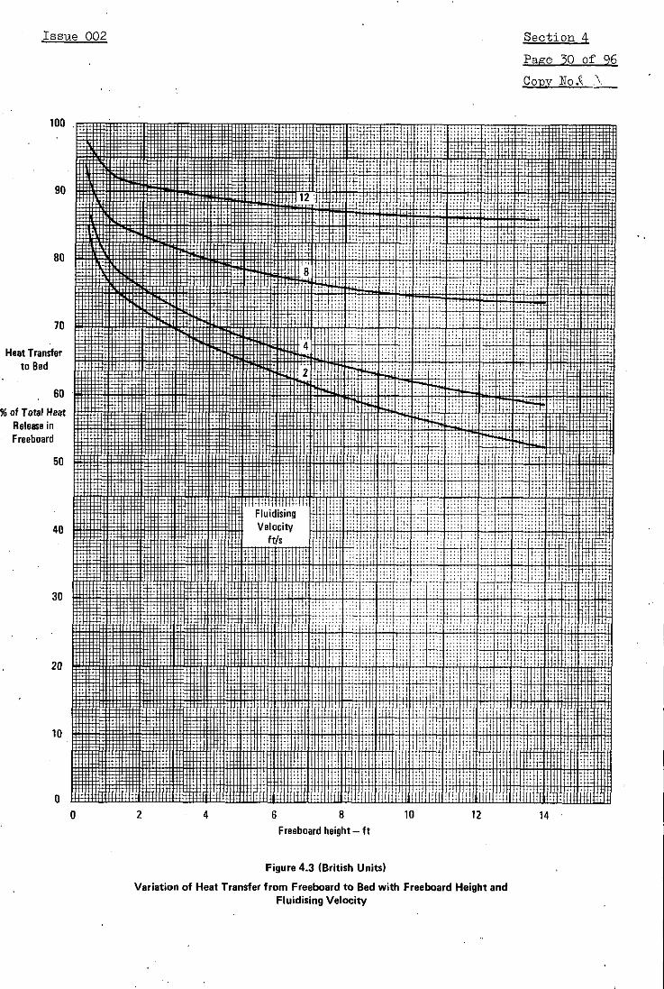
Heat transfer from the whole freeboard to the bed should be
estimated by using Figure 4.3 which is based on the analysis of reference
(4.10).
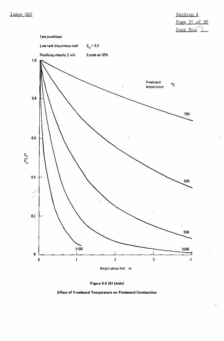
The effect of freeboard height on combustibles loss is shown in
Figures 4.4 and 4.5. Figure 4.4 illustrates the increase in losses which

Issue 002 Section 4
Page 28 of 96Copy Not
will result from drastic cooling at a given height in the freeboard; (at
6600C (1220°F) the reaction rate is only a tenth of that at 8500 C
(1560°F)). It is seen from Figure 4.4 that considerable reaction occurs
just above the bed surface, when the freeboard temperature is 900°C
(1650°F) or above. Except when C is small this causes the off-gases to
heat up rapidly due to the combustion of elutriated and splashing carbon,
and because of this, unless the freeboard is strongly cooled, a high
elutriation rate of carbon is often compensated for by high levels of
freeboard combustion.
Figure 4.5 shows that variations in the fluidising velocity also
have a significant effect on freeboard combustion. An increase in
fluidising velocity from 1 - 3 mls (3.3 - 9.8 ft/s) requires that the
height of the freeboard be increased by about 1.8 times to give similar
values of C /Cto0
When there is substantial freeboard cooling at a certain height,
this has two effects: firstly, by cooling the gases it reduces the rate of
combustion at all higher points; secondly, part of the heat removed by the
cooling will not be available in the bed. The fraction, 6, of the heat
present at a given height in the freeboard which is returned to the bed is
shown in Figure 4.6. It follows that removal of heat at this given height
is equivalent to removal from the bed of 6 times the heat removed. Thus
freeboard cooling, especially if it is positioned not far above the bed
surface, reduces the heat available in the bed.
It is important that excessive cooling surface is not installed
in the freeboard as incomplete combustion may then occur with excessive
carbon monoxide production. In extreme cases the combustion can be
quenched by freeboard cooling.
4.3.2.2 Stepwise calculation of freeboard combustion
This procedure is recommended when it is important that a
critical temperature is not exceeded at any height in the freeboard, and/or

Issue 002 Section 4
Page 29 of 96
Copy No..t.
100 :~ '"-1t - 1:':
10
i - ~ g :! Dj i m ! R 3 X :,' ii, ,il ~ti ~ . i ::' !!i, : -''. ::i~:!,:!'1 ~!i:.i:i ii"
..... ... .. .... :. .. ..70 +: ...: . . .:.... .... ;t:: :* L" , ..... . ii.....
Heat Transfer .................. .: . .. .:
% of Total Heat
Freeboard t . ! ,,,W g !:! :F i ,'':i :: ~::1:: i::'~
+1:: : : ~... .........
40 .L0" .... E 4 - = X::;
30 4
3ii0 0.5 i 1.5 2 2.i 5 3 3.5 4i
Variation of Heat Transfer from Freeboard to Bed with Freeboard Height and.9 l : : :::::::::Fluidising Velocity
Variatio of Hea Transfr from rueboardto Bed ith Freboard Hight au~~~~~~~~~~~~Fdisin VelocitO~~~~~~~~i: '" : ~iiiii
Issue 002 Section 4
Page 30 of 96
Copy No. ".
90
80 i I'
70
* Heat Transferi ::to Bed
60
% of Total HeatRelease inFreeboard
50
Fluidisin g Velocity40 E~aaaFq aKRR iaaBaiaffF iijl i ii#iiiB Velocity
0 2 4 6 8 10 12 14
Issue 002 Section 4
Page 31 of 96
Copv No.
Test conditions
Low rank bituminous coal CO= 0.3
Fluidising velocity 2 m/s Excess air 30%1.0
Freeboard DCtemperature
0.8
700
0.6
Ct
0.4
0.2
1100 1000
0 1 2 3 4
Height above bed m
Figure 4.4 (SI Units)
Effect of Freeboard Temperature on Freeboard Combustion

Issue 002 Section 4
Page 32 of 96
Copy No.H !
Test conditions
Low rank bituminous coal CO = 0.3
Fluidising velocity 6.5 ft/s. Excess air 30%1.0
CZ4 i! !:::: t,i H1 !Freeboard temperature
0.6
0.4
Figure 4.4 (British Units)
0.6
2 1::; i. iiiiiiiii i i~~fiiiw:h E;~~~~ii~
iii~~iiiliiiiliiiiiiiiji iiiiiiiiifiiiiiii sti#... ... . ... ~ ~ ~ ~ ~~ii' iiii ii: ii. Eilsfii 1~!O... ... . ...~~~iii "
Effect of Freeboard T6mperature on Freeboard Combustio n

Issue 002 Section 4
Page 33 of 96
Copy No.'- I
Test conditions
Low rank bituminous coal CO = 0.3
Freeboard temperature 900 GC Excess air 3096
1.0
0.8
0.6
Ct
CO
0.4
Fluidisingvelocity m/s
0.2
0.50O I II
0 1 2 3 4
Height above bed' m
Figure 4.5 (SI Units)
Effect of Fluidising Velocity on Freeboard Combustion

Issue 002 Section 4
Page 34 of 96
G Copy No',i
Test Conditions
Low rank bituminous coal CO= 0.3
Freeboard temperature 1650 OF Excess air 30%1.0
0.8 3 . ...
0:;: ::::i::::
--. 2 S X 0 W X W m iLS , Fluidising 7 m - *
0.6 4 X j
0.4 6 8 10 12
Height above bed ft
Figure 4.5 (British Units)
Effect of Fluidising Velocity on Freeboard Combustion
0.i~~~~~~~~~~~~~~~~~~~~~~~~~~~~~~~~~~~~~~~~~~~~~t;i
Issue 002 Section 4
Page 35 of 96
Copy No.!
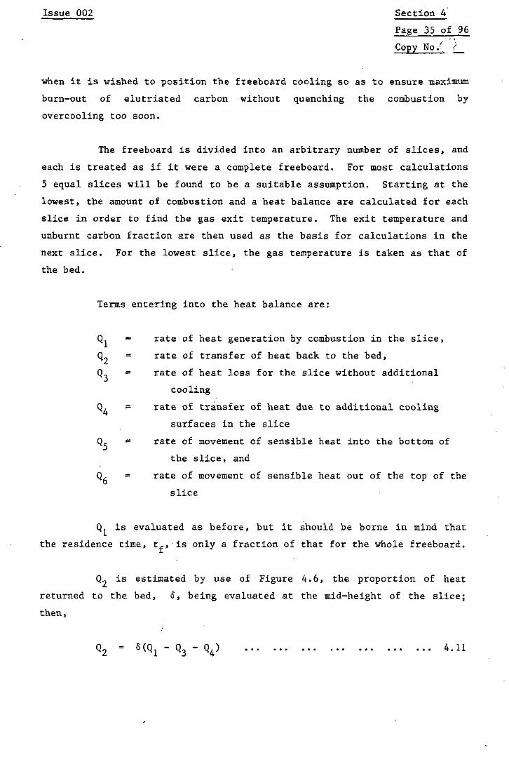
when it is wished to position the freeboard cooling so as to ensure maximum
burn-out of elutriated carbon without quenching the combustion by
overcooling too soon.
The freeboard is divided into an arbitrary number of slices, and
each is treated as if it were a complete freeboard. For most calculations
5 equal slices will be found to be a suitable assumption. Starting at the
lowest, the amount of combustion and a heat balance are calculated for each
slice in order to find the gas exit temperature. The exit temperature and
unburnt carbon fraction are then used as the basis for calculations in the
next slice. For the lowest slice, the gas temperature is taken as that of
the bed.
Terms entering into the heat balance are:
Q1, = rate of heat generation by combustion in the slice,
Q2 rate of transfer of heat back to the bed,
Q3 = rate of heat loss for the slice without additional
cooling
Q4 = rate of transfer of heat due to additional cooling
surfaces in the slice
Q5 = rate of movement of sensible heat into the bottom of
the slice, and
Q6 rate of movement of sensible heat out of the top of the
slice
Q1 is evaluated as before, but it should be borne in mind that
the residence time, tf, is only a fraction of that for the whole freeboard.
Q2 is estimated by use of Figure 4.6, the proportion of heat
returned to the bed, 6, being evaluated at the mid-height of the slice;
then,
Q2= 6(Q1 Q3 Q4) ... ... ... ... ... ... 4.11

Issue 002 Section 4
Page 36 of 96
Copy No. !_
1.0 i i : lit
0.90. 1i i W .2 Fluidising velocity M
0,4
i*= D7iii~ S i X ;. i1: :
0.8
Wc: m g g i-' iwl I N gg R'1 1' 1 .1' 1' i! .3 1' 1i304
0.4
0.7
0
· 0 0.5 1 1.5 2 2.5 3 3.5 4
0P~~~ ~ ~~~~Figure 4.6 S Units)
?--, 0.5
CH .tih is er d - m Lf
F Si
Fhu Hreightabov bh ewould atwheich heAaistracted t- meL

Issue 002 Section 4
Page 37 of 96
Copv No.( .
'1.0 . ' - ' 71 :::-0,
Fluidising velocity ft/s f Ito ... S SiA > :.,, __. __ _-,. *.,..i~. ..... I ............... ~ ...... ~,....... _:_. · '- -,/n ''ff X
.; ' r r w W g X ii..l.. l. . 3 < X siS .S f i ,,, 1.......... . ...... .
3 t _ . ............. . . .-.......... .
0.
, .~-;. . . :4: :ti ; :::u::=:::::::: :::tjj: ::: :: : ....
o. ' S T 'i7. .. u ;W .. .~ ....... ..
...... +. ......I... :i: !;i: ;!;?i::;. .
Height above bedt whichheat ...is exr..... ..- .......
0.6 F"~t. . . ......... !.]!.! ........ ::1Fgr 4..6 . 4!:,.t
These curvec of be in Velocit y by th ................
~' 0.5 + ,,, .. ......... .... .
. l~ +r l :--: ::::-::::-:::::::::
0 2 4 6 8 10 12 14:::
Height above bed at which heat is extracted - ft if
,~~~~.·~~~~Figure 4.6 (British Units).
}'~~, HFreeboard which would otherwise have been Available in the Bed
Ij F r e eboard which would otherwise have been Available in the Bed

Issue 002 Section 4
Page 38 of 96
Copy No.( X
Q3 is calculated by standard methods and represents the heat loss
from the slice without additional cooling. Heat transfer to regions above
or below the slice is ignored. It is convenient to express Q3 as a
function of freeboard temperature for the particular operating conditions
and freeboard wall temperature of a given design. A linear approximation
to this function is suitable as input to the computer program.
Q5 and Q6 are calculated using the assumptions stated on page 27.
Q6 contains a term which may be unknown, the temperature at the top of the
slice, and is found from the heat balance equation:
Q6 = Q. + Q1 .Q2 .Q . ... ... ... ... ... ... 4.12
When equation 4.12 indicates that some critical temperature is
exceeded then equation 4.13, shown below, should be used.
=4 QQ -[ .. ... ... ... ' 4.13
Equation 4.13 gives the amount of extra cooling, Q4, which is
required to maintain that slice below the critical temperature.
The unburnt combustibles loss is found as C at the top of thet
last slice, and the heat returned to the bed is found by summing Q2 for
each slice.
4.4 Overbed Feeding
4.4.1 General considerations
Overbed firing has two particular advantages for fluidised
combustion. Firstly considerable simplification of the coal preparation
and feeding equipment, with resulting cost reduction, is possible if
relatively large coal particles can be fed directly by gravity to the top
of the combustor bed.

Issue 002 Section 4
Page 39 of 96
Copy No.k
The second advantage arises in connection with the adaption of
fluidised combustion to the retrofitting of medium scale industrial boilers
and heaters. If such equipment is to be competitive when converted to coal
firing then the fuel must be readily available and without any need for
further preparation on site. In the UK washed, graded coals such as
"singles" (coal with particles in the range 5 - 30 mm (0.2 - 1.2 in.))
fulfil this specification. The large particle size of such coals implies
the use of overbed feeding but it has been discovered that the fluid-like
properties of a bed of relatively dense material such as silica sand can be
used to "float" the larger particles of less dense coal and the fluidising
process then quickly disperses them uniformly over the bed. The use of
washed coals gives an additional advantage. Most of the ash in them is
inherent and is elutriated from the bed in the gas stream. The inert bed
of sand (or similar refractory) can then be easily maintained with periodic
topping up, although, even when firing washed coal, some large ash
particles tend to accumulate in the bed and it is necessary to remove these
periodically to ensure that the bed remains in a well fluidised state.
Mechanical and aerodynamic classifiers have been developed which withdraw a
stream of bed material, remove and reject oversize particles, and return
the sand to the bed. See Section 15.
The overbed feeding of washed, graded coals has been successfully
carried out in this way in many fluidised bed combustion industrial boiler
installations both in the UK and throughout the world. See, for example,
references (4.15-4.20) and (4.43-4.48). The slumped bed depths used are
typically in the range 0.1 - 0.3 m (4 - 12 in.) corresponding to fluidised
depths of 0.15 - 0.45 m (6 - 18 in.) because depths of this order can be
fitted more easily into existing shapes and sizes of combustion chamber, so
avoiding the necessity for positioning a pre-combustion chamber outside the
boiler when adapting existing designs of plant. A secondary attraction is
that the air delivery pressure can be much lower than for deeper beds, and
fan costs are thereby reduced.
The coals fited using overbed feeding include a wide range of. UK
washed coals with ash contents less than 10%. Washed "smalls" with a top
Issue 002 Section 4
Page 40 of 96
Copy No.'
size of 12.5 mm (0.5 in.) have been burnt in beds 0.6 m (2 ft) deep using a
fluidising velocity of 2 mls (6.6 ft/s). Washed "smalls" sized 12.5 mm to
zero (0.5 - 0 in.), "singles" with particles in the range 5 - 30 mm
(0.2 - 1.2 in.) and "doubles" sized 30 - 50 mm (1.5-2 in.) have all been
burnt successfully in beds with static depths of 0.15-0.3 m (6-12 in.) at
fluidising velocities of 1.5-2.5 m/s (4.9-8.2 ft/s).
The overbed feeding method is not restricted to the feeding of
washed coals. The method has been used on the industrial scale
successfully for feeding coals with ash contents up to 18% and in research
equipment for low grade coals with ash contents up to 80%. Changes in the
design of the air distributor and ash removal system are required, however,
to handle the combustion of high ash coals. Once the ash content exceeds
about 15% sufficient ash particles are introduced to form the bed solids;
the start-up sand bed becomes replaced by an ash bed and continuous ash
removal and bed regrading becomes necessary. Various distributor designs
are available that are suitable for such duties; see Section 15.
Although the heating, devolatilisation and combustion of large
lumps of coal is slower thanrwith crushed coal (4.1), the evolution of
volatile matter in the vicinity of the coal feed point may be sufficiently
rapid to cause a deficiency of oxygen, particularly when the coal feed is
of an intermittent nature as might result from operation of a rotary valve
or ram feeder. In such cases, the delivery of a pulse of coal may be the
cause of a puff of dark smoke from the chimney unless an adequate supply of
air is available in the freeboard to ensure complete combustion of the
volatiles. This may be done by installing secondary air jets above the
bed. By increasing freeboard mixing these also generally improve the
burn-out of elutriated char particles. It is found that satisfactory
operation is obtained if excess air levels are in the range 20-30% and bed
areas up to 8.0 mi (86 ft 2) are supplied from a single source depending on
the coal feed arrangement.
The combustion rate depends on the surface area of the coal and
is lower, therefore, for larger coal particles. In consequence, above bed
feeding results in higher bed carbon contents than are found for the in-bed
Issue 002 Section 4
Page 41 of 96
Copy NC.;k
feeding of crushed coals. The bed carbon content can be as high as a few
percent, compared with about 0.1% in in-bed feeding of crushed coal. A
further result of the higher bed carbon content is that response times to
changes in coal feed rate are longer. During the overbed firing of a
"singles" coal time constants, t , of about 10 minutes are normal, compared
with 2 to 8 minutes when in-bed feeding. See also Section 13.1.5.
While the presence in the feed coal of fine particles, of a size
rapidly elutriated from the bed, does contribute to some extent to the
unburnt carbon in the gases leaving the combustor, a series of tests on a
vertical shell boiler, using a range of coal types and size distributions
has shown that coal rank (as indicated by oxygen content), bed temperature
and excess air level are the most important parameters governing combustion
efficiency (4.47).
4.4.2 Overbed feeding techniques
In overbed firing the coal feed is introduced into the combustor
very simply by gravity feeding through a vertical pipe or inclined chute
which may pass down through the freeboard or through the side of the
combustor. This feed tube may terminate at the combustor wall or be
extended to about 1 m (3.3 ft) above the expanded bed surface. Providing
the fluidising velocity is sufficient to provide vigorous bed particle
circulation and mixing, the location of the feed point is not critical.
Combustors have been operated successfully with a feed point at one end of
a rectangular bed (4.17) or offset from the centre of a circular bed
(4.15). Bed areas up to 4.0 m2 (43 ft2 ) have been fed from a single feed
point using a drop tube feeder.
Another possibility for overbed firing is to use a spreader
stoker or blast of air to distribute the coal over the bed. Beds up to
8.0 m (86 ft2) have been supplied from a single point by this means. It is
to be expected that distribution in this way of a coal containing a large
amount of fines would result in an unduly high unburnt carbon loss because
the fines would be more likely to become entrained by the off-gas than when
the coal is dropped in a compact mass into the bed.

Issue 002 Section 4
Page 42 of 96
Copy No. AK
4.4.3 Estimation of combustion efficiency
No systematic investigation of the combustion taking place in the
bed and in the freeboard separately has been conducted for overbed feeding
of large coal or smalls. However, a series of tests has been carried out
with various coals on one vertical boiler (4.47), in which overall
combustion efficiencies were measured for a range of coal types and size
distributions. There is also a fair amount of test data for limited-range
operation of other industrial fluidised-bed boilers.
The most important controlling parameters have been found to be
the coal rank (indicated by the coal oxygen content), the excess air level
and the bed temperature. The dependance of the combustion efficiency on
each. of these is illustrated by Figures 4.7, 4.8 and 4.9. These Figures
show the variations in combustion efficiency found for one particular
industrial fluidised combustion installation (4.18, 4.47) and should be
considered as illustrative only, although the trends shown are likely to be
similar for other combustors.
Some work has been carried out on deriving a generalised
correlation for the combustion efficiency of bed and freeboard together
during overbed feeding (4.47). The correlating parameter used is the
fractional combustibles loss, (1 - n). The combustion efficiency as a
percentage is given by,
Combustion efficiency = 100 [1 - (1 - n). .. ... ... 4.14
4.4.3.1 Combustion efficiency correlation 1
The first correlating equation that has been derived is based on
just the three most important variables, bed temperature, excess air level
and coal reactivity (characterised by the coal oxygen content). The
equation is,
1-n x ( 0 - 1b- [) 0. 035 + exp (-3.7 + 0.17 0) (1 + ... 4
57 [0.008(Ox + 1) + 0.181
The constant, 0, is 1.0 for SI Units and 1.8 for British Units.

Issue 002 Section 4
Page 43 of 96
Copy No.,i ')
Bed temperature OF
1300 1400 1500 1600 1700 1800100
Combustionefficiency
90
Test Conditions
No fines recycle.Excess air level 30%.
.... .......... ~~j i.....,~ !Fluidising velocity 1.8 m/s 15.9 ft/s).,+W : .:.,.,,::. - .. .........Static bed de th 160 mm (6.3 in.).
* 80
700 800 900 1000
Bed temperature °C
Figure 4.7
Typical Effects of Bed Temperature on Combustion Efficiencyfor Overbed Coal Feeding

Issue 002 Section 4
Page 44 of 96
B COPV No.
T eiciency
. ... ....
90 4 w
Combuo Obe t Conaediti n
I:~~m.. . . :;;;;;;...:..:;;; Bituminous coal, oxygen content 10% dmmf.i.. . . . ................ .. .. _ No finesrecycle.
!!T:~l:~q!!!.... ..3 !!'! !! Bed temperature 860 °C (1580 oF). ...?'}11~:. ._ 1~: : !! ...... _ l ? ii!!! Fluidising velocity 1.8 m/s (5.9 ft/s).
:H:[:[;................. _ _ _ _ Static bed depth 160 mm (6.3 in.).
-40 -20 0 20 40 60 80 100 120
Excess air level %
Figure 4.8
Typical Effects of Excess Air Level on Combustion Efficiencyfor Overbed Coal Feeding

Issue 002 Section 4
Page 45 of 96
Copy No.'
100
::. ii1ii_
Combustionefficiency ,
90 MMUMM KVWC o contenS Et :% :w: d i
forE9 IM1414:~ Test Conditions C Fie
... ~ No fines recycle.Bed temperature 860 oC (1580 OF).
M E ' ........... Excess air level 30%.~~ I~I~.0~~~~~~ Fluidising velocity 1.8 m/s (5.9 ft/s).
.,,, H t Static bed depth 160 mm (6.3 in.) .
80 , i Rt,0 2 4 6 8 10 12
Coal oxygen content % w/w dmmf basis
Figure 4.9
Typical Effects of Coal Reactivity on Combustion Efficiencyfor Overbed Coal Feeding

Issue 002 Section 4
Page 46 of 96
Copy No.,
4.4.3.2 Combustion efficiency correlation 2
When comparing predictions using correlation 1 with recent
experimental data a consistent small discrepancy was noted which has
subsequently been reconciled by the introduction of an expanded bed depth
term. While reformulating the correlation the equations have been modified
to enable combustion efficiencies of 98% to be predicted from high
reactivity fuels, under conditions of high excess air and high bed
temperature. This has been done to reconcile combustion efficiency
predictions and measurements for the operation of fluidised bed furnaces.
The correlation 2 equation is,
(1 - n)c exp [(8100 e)/T;]
(1 - n) = ... ....... ... 4.16
1273 [0.18 + 0.0064 (0 + 1) 2
The constant, E, is 1.0 for SI Units and 1.8 for British Units. The
parameter (1 - n) is found from,
1 - (1 - n)c = (1 + 0.01 Xc) [1 - 0.05 ... ... ... ... ... 4.17
and =- ... ... ... ... ... ... ... 4.180.05 (1 + 0.01 X )
Equation 4.17 has the same form as equation 4.4 for a Cj value of 0.05, and
may be solved similarly by trial and error, or by reference to Figure 4.2
or Table 4.1. In equation 4.17 the excess air is expressed as a corrected
value, X , which allows for the effects of the non-uniformity of coal
concentration in the bed and the rapid evolution of volatile matter close
to a coal feed point which may result in a local starvation of oxygen.
The corrected excess air level is calculated as follows.
For Lb4 650 mm (25.6 in.),
X = X - 0.00413 0 (650 - Lb) ... ... ... ... 4.19c X

Issue 002 Section 4
Page 47 of 96
Copy No./
For Lb > 650 mm (25.6 in.),
X = Xc
The constant, 0, is 1000 for SI Units and 305 for British Units. If the
expanded bed depth, L, is unknown it can be estimated from the static bed
depth, L , using the following correlation.
L(1-= V.. ... ... ... ... ... ... ... 4.20(1 - V) (1 -VB)
where,
V = Uf Umf 4.21
B Uf Uf + 0.71 z + 4Ut
The minimum fluidising velocity, U can be calculated from
equation 3.1 or 3.2 in Section 3. The parameter z should be taken as the
horizontal gap between the in-bed heat transfer tubing. If no tubes are
present then z, represents the maximum bubble diameter. In that event
suitable arbitrary values for z are: for combustors with bed
cross-sectional areas up to 0.2, mn2 (2 ft2) - 50 mm (2 in.); for combustors
with bed cross-sectional areas' over 0.2 m2 (2 ft2) - 100 mm (4 in.). The
constant in equation 4.21, 0, equals 1000 for SI Units with z in mm and g
in mr/s2. For British Units with z in inches and g in ft/s2, e equals 12.
Equations 4.20 and 4.21 may be used to estimate Lb for most
materials used as bed solids. For 14/25 grade silica sand, which is
commonly used as bed solids in industrial boiler installations, the
following empirical correlation will give a more accurate estimate of
Lb (4.42).
For L >0.163 m (0.534 ft),
Lb = L (0.3 Uf + 1.12)
For 0.163 > L > 0.133 m (0.534 > L > 0.436 ft),S S
Lb =L (0.3 u + 1.88 -4.667 L 0)
where e = 1.0 for SI units and L in m and 0 = 0.305 for British units andS
L in ft.S

Issue 002 Section 4
Page 48 of 96
Copy No.Jt2J
For L < 0.133 m (Ls < 0.436 ft),
Lb = Ls (0-3 U f + 1.26)
For empirical correlations for other grades of sand and for
certain coal ashes reference (4.42) should be consulted.
4.4.3.3 Choice of correlation
Values of combustion efficiency predicted by the two correlations
are compared in Table 4.3 for typical operating conditions (excess air 25%,
fluidising velocity 2.2 m/s) of a boiler at the two extremes of coal
reactivity and at two expanded bed depths. The values predicted by
correlation 2 are higher. The correlation 2 values are supported by
experimental values for the high reactivity coal (10% oxygen) but
unfortunately no practical data is yet available for comparison from the
combustion of low reactivity fuels (1% oxygen) at excess air levels above
15%. It is recommended, therefore, that the more optimistic predictions of
correlation 2 for low reactivity fuels be treated with caution pending
experimental verification.
Table 4.3
Comparison of Predicted Combustion Etficienciesfor Overbed Feeding
Bed depth Coal oxygen content
Correlation 1% dmmf 10% dmmf
Static Expanded Bed temperature 'C
mm mm 900 950 900 950
1. Eq 4.15 Not bed depth 85.2 87.4 95.8 96.4dependent
2. Eq 4.16 150 267 87.8 90.8 96.8 97.6200 344 87.8 90.8 97.0 97.7
Note: Predicted efficiencies for excess air level of 25% and fluidising
velocity of 2.0 mis.

Issue 002 Section 4
Page 49 of 96
Copy No.i ,l
4.5 Methods of Reducing Unburnt Carbon Loss
Maximum carbon utilisation is necessary for efficient and
competitive use of coal in fluidised bed combustors. In modern pulverised
coal fired water-tube boilers the combustion efficiency exceeds 99.5Z, and
it is probable that for this type of use, an efficiency much less than this
could not be tolerated. For the smaller, industrial boilers, however, a
lower combustion efficiency, down to say 97% could be accepted, and when
burning a very poor grade of fuel a loss of 5% could be tolerable.
Occasions can arise, therefore, when the combustion efficiencies of
fluidised bed combustion obtainable with once through operation may need to
be increased for economic operation. The causes and methods of reducing
carbon loss are reviewed in this section - the review of carbon loss
reduction given in reference (4.21) may also be consulted.
If the coal feed points are not too widely spaced, if adequate
gas mixing occurs in the freeboard, and if the excess air is not less than
10%, then the combustible losses in the form of carbon monoxide and unburnt
volatiles should be small, and the main concern is with elutriated unburnt
carbon.
The elutriated particles come from five different sources: (i)
the fines content ot the feed coal; (ii) thermal shattering of particles
when they are suddenly heated in the bed; (iii) reduction in coal particle
size due to combustion, causing the particles eventually to become small
enough to be elutriated; (iv) fine ash particles liberated by the burning
coal; and (v) breakage of coal and bed material due to the particle
jostling always encountered in fluidised beds. These sources of elutriable
material are all interdependent; an increase from one source may well
cause a decrease from another. Of particular interest are the carbonaceous
particles, and these come principally from sources (i), (ii), (iii) and
(v). Source (i) can be estimated directly from the coal size distribution,
and (iii) can be estimated indirectly by calculating the number of coal
particles per unit weight of feed, and thence finding the total weight of
these particles when they are just small enough to be elutriated. The

Issue 002 Section 4
Page 50 of 96
Copy No.,'>
rates of the other sources will depend on the coal hardness and resistance
to thermal shock.
The following courses may be considered for reducing the loss of
elutriated carbon particles.
1. Use of a higher bed temperature. This is limited to coals having
a higher ash fusion temperature than normal. Also with most
sulphur retention additives performance decreases above certain
bed temperatures. See Section 11.
2. Optimisation of combustor and freeboard design. Factors likely
to favour improved burn-out are: deeper freeboard; avoidance of
over-cooling of freeboard gases; use of baffles to facilitate
the return of particles to the bed; and use of a "flared"
freeboard to reduce gas velocities.
3. Recyling of fines collected by an internal or external cyclone.
4. Use of a separate bed to burn the carbon collected in a cyclone
collector.
5. Use of a lower fluidising velocity in the main bed with a smaller
coal size, at the expense of reduced heat release per unit area
of bed.
6. Increase in excess air level. The improvement in burn-out is
small above about 15% excess air with in bed feeding and 30%
excess air with over bed feeding, and there are other penalties:
reduced boiler efficiency, and excessive use of fan power. Scope
for improvement by this means is not great.
7. Reduction of fines content of coal feed.
Some of these measures will now be discussed in more detail.

Issue 002 Section 4
Page 51 of 96
Copy No.
4.5.1 Freeboard baffles
There is some evidence that the elutriation of unburnt carbon can
be reduced by positioning a baffle comprising one or more rows of tubes up
to about 0.5 m (19 in.) above the surface of the bed. It is likely that
this acts in two ways; firstly, by physically intercepting particles
ejected from the bed when bubbles burst, and causing them to fall back into
the bed and, secondly, by smoothing the gas velocity profile. It is
important, however, that if the baffle is to be cooled, the cooling must
not chill the freeboard gas to a point where combustion is unduly retarded.
4.5.2 Combustion of elutriated carbon in a separate bed
The material elutriated from a fluidised combustor fired with a
fines-containing small coal (for example with a top size of 1.7 mm
(0.067 in.)) consists of a mixture of ash (and additive, if used) and
incompletely burnt coal particles. Section 9 explains how the rate of
elutriation may be calculated, given a knowledge of the friability of the
ash (and additive). It should be noted here that particles of inert bed
material and additive have particle densities ranging from about 1800 to
2900 kg/m 3 (110-180 lb/ft3 ). Carbonaceous particles on the other hand, are
generally less dense at 1500 kg/m 3 (90 lb/ft3 ) or less. The top size of
carbonaceous particles elutriated will therefore be larger than the top
size of bed material elutriated, but otherwise the same principles apply.
The factors governing the distribution of carbon with particle
size of the elutriated fines are complex, and include the following:
(a) Combustion factors: The larger the particles the longer they are
likely to stay in the bed before they are elutriated. Hence they
have a greater chance of being burnt or broken into small
particles before they are elutriated. Very small particles burn
quickly, but may not meet sufficient oxygen during the short time
they are in the bed to allow them to burn completely. Therefore,
the particles leaving the bed surface will include many

Issue 002 Section 4
Page 52 of 96
Copy No.
carbonaceous particles which are very small. In the freeboard,
the finer particles burn away more quickly, but they spend a
shorter time in the freeboard because of their lower terminal
velocity (causing less `slip` through the rising gas stream).
All particles smaller than a certain size, (depending on particle
residence time, freeboard combustion rate constant and oxygen
concentration) are completely burnt, while a smaller number of
particles will be burnt down to this size from larger sizes. At
low or negative excess air values, the carbon content of the
finest size fractions is significantly increased.
(b) Elutriation of inert material: This affects the concentration of
carbon in different size fractions, but not the distribution of
the carbon with particle size. The net effect will depend on
whether or not fines recycle is practised. In the absence of
recycle, the elutriation rate of inert fines is the sum of the
rate of feeding fine mineral particles in the coal (and any
additive), plus the rate of production of fines due to thermal
effects or abrasion in the bed. When fines are being recycled to
the bed, the inert mineral content of the elutriated material is
much greater. Most of the additional material will be in the
form of particles larger than the cyclone "cut" size, but some of
the recycled particles will be broken during passage through the
recycle system and the bed. The net effect, however, is to
reduce the concentration of carbon in the coarser elutriated
fractions.
By way of illustration, for a primary cyclone designed to "cut"
at 10 pm (0.0004 in.) an average carbon content of primary
cyclone fines, as collected for refiring, is about 20%, roughly
half of the carbon being contained in particles smaller than
40 pm (0.0016 in.) for fluidising velocities of 0.6 - 2.4 m/s
(2 - 7.9 ft/s) and normal excess air levels in a combustor with a
3.7 m (12 ft) uncooled freeboard and using in-bed feeding. In
many industrial installations with overbed feeding the carbon

Issue 002 Section 4
Page 53 of 96
Copy No.q'
content of the elutriated material is in the range 30-50% with
about 20% of the chimney dusts containing carbon particles less
than 10 pm (0.0004 in.).
The efficient combustion of such fine carbon in a separate
burn-up bed usually requires either a very low fluidising velocity, to
increase residence time, or a very high bed temperature, to increase
reaction rate. The chief advantage of using a separate bed is that such
conditions can be obtained independently of the conditions in the main
combustor. The disadvantages of adopting a separate fines burn-out bed
are:
(a) The need to provide additional bed area and increased air
requirements.
(b) The probability that the heat release will be inadequate to
allow a worthwhile amount of heat transfer in the bed.
(c) Possible difficulties of control resulting from fluctuating
carbon input; it might prove necessary to provide a
supplementary fuel supply for control purposes.
4.5.2.1 Carbon burn-up cell design with in-bed feeding
The following stepwise procedure is proposed for the design of a
fines combustion bed using in-bed feeding. The procedure takes account of
the fact that the size distribution of the combustible matter is
considerably finer than that of coal normally fired at the same fluidising
velocity.
1. Calculate the combustible loss, CO which would be expected from
the surface of a bed at the same operating conditions, but fired
with coal.
2. Multiply this value by the factor [3(1 - C ) + CO = to obtain the

Issue 002 Section 4
Page 54 of 96
Copy No.&
combustible loss from the surface of the fines combustion bed,
C', i.e.
C' = C [3(1 - C ) + C 2. ... ... ... ... ... 4.220 0 0 0
3. Calculate the combustion in the freeboard and heat transfer to
the bed as in Section 4.3.1.2.
The procedure predicts that fines combustion is likely to be
extremely inefficient at fluidising velocities in excess of 2 mts, at
normal bed temperatures.
4.5.3 Refiring of fines to the main bed
It has been found possible to improve combustion efficiency by
refiring collected fines to the main combustion bed, though the improvement
obtained has varied widely with the design of the recycle system and with
the operating conditions. External cyclones are recommended and the fines
are fed using the overbed feeding method. Table 4.4 summarises the results
obtained during experiments using in-bed feeding. Limited data suggests
that similar improvements in combustion efficiency are possible when above
bed feeding is used (4.48).
Refiring or recycling of fines has three advantages over
combustion in a separate bed:
(a) It does not necessarily increase the required bed area or
combustion airflow.
(b) In cases where maintenance of the required bed depth is
difficult refiring of fines will help, as discussed in
Section 3.1. It is will also increase the heat transfer
coefficients to tubes in the bed because of the reduction in
mean bed particle size. A further consequence is that the
increased dust burden of the freeboard gases will improve

Issue
002 S
ection
4
Page
55 of
96
£o_pyNo.
cn 10
CD
:r
CO
ui CO
0�
CD
00 C
�0
cn 10
0
W
0 CD
cn
cn
0 It
Ln
000
a�
1-1 L
n In
CO C)
0 'D
�D
C) r
CD
bc 0
CO 00
r. cj
C9
W
Go
N
0 L
nW
cn
CD C
) t
00
bo C
O-14
cq cn
0W
JC
C4
CO cm
(M
-�r 10
C;
00
on C
D
>U
0
a,
CD
rq
I.:00
C4
N
cm
rm cm
CD
0 rn
cn00
m
CO
-IiU�
0W
0
CD
1-� C
O
0.Q
m
4
cn 0
C4
0 U
CO
�4
0) rn
rn C
D
1 W
W
m
CO
Ln
n m
m W
en N
w
0
U0
CD ;j
CA C
71 0
c �d
m
C)
1 0
W
00 C
D.H
C
D
W
0� CD
1.� c
040 10
10 0
CD
0L
Q
0
rzIS -m
1-4
U
UC
0
0
:5 Q
�d W
�o r
0 :i
W
U
1-4 W
�4
W10
W
-1� -1�
0 $m
-1-1
UC
O
0 m
c
Q)
0
1.4 4�
r.0
r: 0
12-1�
0rn
14
_0 r
�zed
0 'i
0 0
>,
Prw
U
U
W

Issue 002 Section 4
Page 56 of 96
Copy No. '
the emissivity and heat capacity of the gases and therefore
improve heat transfer rates in the freeboard. However, a
disadvantage is that the load on the gas cleaning equipment
will be increased.
(c) Where an additive is used to retain sulphur, the retention
efficiency may be improved by recycling solids.
The gains in combustion efficiency that can be obtained by
refiring fines to the main bed are limited by many factors, including:
(a) The maximum recycle rate is limited by the efficiency of the
dust collection equipment. The particles passing
uncollected through this equipment can contain substantial
amounts of unburnt carbon.
(b) Where elutriated solids are cooled before being collected
and refired, a limit on recycling would be imposed by the
acceptable amount of heat removed from the bed at the
expense of heat transfer in the bed. It would also be
necessary to dispense with freeboard cooling.
(c) Collection and recycling of large amounts of fine
particulate material may often present mechanical and
control problems, thus limiting the recycle ratio that can
be used.
There are strong attractions in fines recycling, although when a
very high combustion efficiency is required a separate burn-up cell may be
necessary.
4.5.3.1 Combustion loss estimation for fines recycle with in-bed feeding
When the in-bed feeding method is used the calculation procedure
outlined in Section 4.3 can be modified to account for fines recycle.

Issue 002 Section 4
Page 57 of 96
Copy No.
A rough estimation of the reduction in unburnt carbon heat loss
which can be obtained through fines recycling may be made by referring to
Figure 4.10. Detailed calculation of combustion losses with fines recycle
are carried out using the following stepwise procedure.
1. Calculate the combustible loss from the bed surface resulting
from incomplete combustion of freshly fired coal, C , using
steps 1-3 of Section 4.3.1.1.
2. Calculate the combustible loss in the off-gas, Ct, as for a
combustor without fines recycle, using Section 4.3.1.2 and 4.3.2.
3. Derive the probable size distribution of the unburnt carbon in
the elutriated particles from Figure 4.11, and apply the cyclone
grade efficiency to calculate X, the proportion of the carbon
leaving the bed that is collected by the recycle cyclone. It
should be noted that, whereas the size distribution of the total
fines changes considerably when recycling is practised (becoming
much finer), the size distribution of the carbon changes much
less, because a large fraction of this burns away during each
passage through the combustor. X may therefore be assumed to
remain constant through the calculations.
4. The rate of carbon refiring to the bed, C , is calculated by
multiplying X by Ct and by the fraction of the collected fines
which are to be refired to the bed. The quantity of carbon
rejected in the case of partial fines recycle can also be found.
5. Calculate X , the effective excess air, from:e
(100 + X)X = - 100 ... ... ... ... ... ... 4.23e (1 + Cr)
6. Calculate the combustible loss from the surface of a fines
combustion bed at the operating conditions of the main bed and

Issue 002 Section 4
Page 58 of 96
Copy No.k
mo~ S.0a
oQ cli
oloomD ;3C
=
Figure 4.10
Estimation of the Reduction in Unburnt Carbon LossObtainable by Recycling Fines
Using In-bed Feeding
#r#t~~~~~mttmt~~~~~mhKh~~~~iittiWKf~~~~~~~~~mtittt~~~~~~KRmAKKR ~ ~ ~ 0
'# %~~~~~~~~~~~~~~~~~~~~~
i~~-t't~tFR4fAFRfFF~PFm;FmRsRFFF;·F~ Y,~
iiFf;~~~~fFi~~~Rm~~dfftmftffKK-·;#K~~~~~~~~RtX#~~~#t#####f ~ ~ C
c~~~~~~~~~~~~~~~~~~~~-*~~~~~~~E;FiEff-;rIu!~· s nr o ~~~~~~~~~~~~~~~~~~~~~~n o~~~~~~-
C~~~~~~~Otial -y 0eyln i
o~~~~~~~~sigI-e edn

Issue 002 Section 4
Page 59 of 96
Copy No.
excess air level Xe, by the method given in Section 4.5.2, steps
1 and 2.
7. Multiply C by this proportional loss from the surface of a fines
combustion bed to calculate C f' the quantity of recycled fines
leaving the bed surface after one recycle, as a fraction of the
carbon feed-rate with fresh coal.
8. Add Cof to C c to obtain C , the total loss of combustibles from
the bed surface after one recycle.
9. Calculate the total loss of carbon in the fines at the top of the
freeboard, Ct, as in Section 4.3.1, but using the excess air
level Xe
10. Repeat steps 4 to 9, using this new value of Ct, until the values
of parameters C , Ct and Cr converge to constant values.
11. Calculate the total carbon loss, namely the carbon fines passing
through the cyclone plus those rejected if a partial recycle
system is used.
12. Calculate the amount of combustion occurring in the freeboard, Cf
from,
C = C Ct
Because of the tedious nature of these repetitive calculations it
is recommended that they be performed on a computer. The computer program
(4.8) can be used to calculate combustion alone, or in conjunction with
other design aspects such as elutriation and abrasion of ash, tube-bank,
etc.
In addition'to the recycled carbon there will also be a large ash
recycle rate, the magnitude of which will depend on the ash abrasion
properties. This recycle rate should be calculated as in Section 9, and

_Issue 002 Section 4
Page 60 of 96
Copy No4> ;
E
S t n
- | +XnE
Figure 4.11 (SI Units)
Size Distribution of Unburnt Carbon Fines

Issue 002 Section 4
Page' 61 of 96
Coypv No. , ,K_
' .
! u.
Figure 4.11 (British Units)
Size Distribution of Unburnt Carbon Fines
2°tSot 19g 2 ] 1 lb tSllZ#I t~~~~~~~~~~~~~~~~~~~~~~~~~~~~~~~~~~~~~~~~~~~~~~~~~~~~~~~~~~~~~~~~~~~a

Issue 002 Section 4
Page 62 of 96
Copy No. .?
will to a large extent determine the design of the recycle systei for a
required improvement in combustion efticiency.
In order to design a fines recycling system for given
coal/combustion/operating parameters it is recommended that the above
procedure be applied for a range of different recycling rates, and the
amount of ash/additive recycle at each rate be also calculated. It will
then be possible to select an optimum recycle rate.
4.5.4 Reduction in fines content of feed
For in-bed feeding there is no apparent relationship between
overall (bed and freeboard) combustion efficiency and the fines content of
the feed. This may be because a lower bed combustion efficiency is, in
most instances, compensated by an increase in freeboard combustion.
For over-bed feeding, coals with appreciable fines content have
in some instances given significantly lower overall combustion
efficiencies, but more recent work has shown the coal size distribution to
be much less important than coal reactivity in determining overall
combustion efficiency.
4.5.5 Operation at higher temperatures or higher excess air levels
As discussed in Section 3, constraints imposed by such factors as
ash softening temperature and overall thermal efficiency and fan power
requirements limit to a large extent the freedom of choice in respect of
bed temperature and excess air. Nevertheless, there may be occasions when
a significant increase in combustion efficiency is possible by a moderate
increase in one or both of these operating parameters.
When firing unreactive fuels such as anthracite, the high.
elutriation rates of unburnt carbon result from the low specific reaction
rate of the fuel in the bed and the reduced burn-out rate of char in the
freeboard. This may be to some extent countered by operating at higher bed

Issue 002 Section 4
Page 63 of 96
Copy No.
and freeboard temperatures, because the chemical reaction rate of the coal
increases with temperature according to the well-known Arrhenius
relationship although the mass transfer component of the overall combustion
process is little affected by changes in temperature. The use of higher
combustion temperatures is generally only practicable if the coal ash has
an unusually high fusion temperature. Where it has been possible to
operate at, say 1000°C instead of 900%C, (1830°F instead of 1650°F), marked
reductions in unburnt carbon loss have been found.
Up to a certain level of excess air (depending on the fuel type
and operating conditions), the combustion efficiency is increased by
increasing the amount of excess air. This critical level is about 15% for
crushed coal firing in static beds not less than 0.6 m deep, but it may be
as high as 30 or 40% for some shallow bed units in which uncrushed coals
are fed over-bed.
4.6 Assessment of Coals for Suitability in Fluidised Combustors
Although the procedure described above is adequate for the design
of combustion systems for well-characterised fuels, the need sometimes
arises for assessment of fuels of unusual properties. A number of test
facilities which may be used to obtain design data for use with such fuels
are described in Section 17.
4.7 Effect of Coal Characteristics on Combustor Design and Operation
4.7.1 General effects
A number of coal properties have- effects on the operation of
fluidised combustors, although as remarked earlier (Section 2.1) fluidised
combustion systems are more versatile as regards fuel properties than are
most conventional systems. Coal properties that may affect the operation
and design requirements are discussed in this Sub-Section.
Changes in some coal properties can affect the combustion process

Issue 002 Section 4
Page 64 of 96
Copy N.0';°
itself; e.g. coal reactivity. Equally importantly, however, are the
changes that can occur in the combustor heat balance and the bed
fluidisation characteristics through changes in coal properties.
A fluidised bed combustor is designed to have a precise heat
balance in the bed at MCR conditions so that the design bed temperature
remains constant at the design values of excess air, coal flow and
fluidising velocity. To obtain the necessary heat balance the following
conditions must be met.
1. A specified heat release must occur in the bed for specified
fluidising velocity. This implies certain design values for
bed temperature, excess air, coal flow and coal quality.
2. A fixed ratio must be maintained between the heat removed
from the bed as sensible heat in the gases and that removed
by heat transferred to immersed surfaces (cooled walls and
in-bed tubes).
3. The quality of fluidisation must be satisfactory at all
operating conditions.
If the fuel properties are altered by the substitution of one
coal for another then concomitant changes may occur in one or more of the
above conditions which may result in a bed MCR heat balance occurring at
conditions of bed temperature, fluidising velocity and excess air level
that differ from the design values. Some latitude in operating conditions
can normally be accommodated but extreme changes in fuel properties can
affect the combustor rating.
Some examples may clarify the above argument. For instance, an
increase in coal moisture content will alter condition 2. The combustor
will now have too much immersed surface heat transfer and a heat balance
will be obtained at a bed temperature less than the design value. Again, a
reduction in coal reactivity will reduce the combustion efficiency and

Issue 002 Section 4
Page 65 of 96
Copy No. ;)
hence the heat release, thereby changing condition 1. Increases in coal
ash content can produce several effects. An increase in the coal flow will
be needed to maintain condition 1. Bed cleaning methods may need
altefation to maintain condition 3. With ash contents above about 15% the
ash particles replace the sand as the bed solids. The flat plate type of
air distributor may no longer be suitable and continuous ash removal and
bed cleaning may become necessary. The fluidisation characteristics of
beds of coal ash are somewhat different from those of some beds. In
particular, the bed expansion characteristics are different, so condition 2
becomes changed. This is important if the bed expansion method of turndown
(see Section 4.10) is used.
The effects of particular coal characteristics are considered in
more detail below.
4.7.2 Moisture content
Moisture has no significant effect on the combustion process
itself but an increase in the moisture content replaces the coal calorific
value and alters condition 1 above.
Coals containing substantial proportions of fine particles are
often extremely difficult to handle if the free moisture content exceeds
the inherent moisture content and this must be taken into account when
designing the coal supply and feeding systems. The types of difficulty
likely to be encountered are: adhesion of fine coal to metal surfaces;
failure to flow down chutes and from bunkers; blockage of conveying
systems, etc.
On the other hand, coals with a high fines content should not be
too dry as the moisture has been found to stick the fines together so that
they remain in the combustor for long enough to be burnt and not instantly
elutriated. An optimum moisture content can be described by the phrase
"moist but not wet" and often corresponds to a free moisture content in the
range 5-7%.

Issue 002 Section 4
Page 66 of 96
Copy No '
4.7.3 Swelling number
Certain coals, especially those in C.R.C. groups 200 to 600
exhibit swelling and caking on heating. The main design consideration is
to ensure that swelling and caking cannot occur while the coal is being
conveyed into the bed, thus causing blockage of the feed line.
4.7.4 Coal rank
It is known (4.13) that the chars derived from high rank coals,
such as anthracite and semi-anthracite, are less reactive than those
derived from low-rank coals. This factor is taken into account in the
combustion calculations of Section 4.3 by applying correction factors to
the combustion losses from the bed and freeboard.
Some comparisons of anthracite combustion with that of low-rank
coals have been obtained for over-bed firing of large coal (4.16, 4.18).
Using the coal oxygen content as an indicator of coal rank the results
obtained have been used to develop the correlation for combustion
efficiency given in Section 4.4.3. As the coal oxygen content is reduced
the coals become progressively less reactive and, if all other operating
conditions are kept constant, the combustion efficiency is decreased in the
manner illustrated by Figure 4.9.
Similarly a lignite has been burned with a combustion efficiency
of 99% compared with a 93% efficiency for a bituminous coal of similar ash
content fired at similar operating conditions (4.21). This increase in
efficiency is attributable to the higher reactivity of lignite.
Coal rank also has a marked influence on the temperature to which
a fluidised bed must be raised during start-up before self-sustaining coal
combustion begins. This temperature can vary from 400°C (7500 F) when
lignite is the fuel to 700°C (1290°F) for anthracite fuels or 800C
(1470°F) for petroleum coke. A simple laboratory test, described in
Section 17, has been developed to assess the reactivity of a given fuel.

Issue 002 Section 4
Page 67 of 96
Copy No. _
The test results and a knowledge of the heat losses expected from the
combustor during start-up can then be used with a computer program to
obtain an estimate of the fuel ignition temperature in the given combustor.
4.7.5 Ash content
The different ways in which the mineral matter content may be
distributed have been described in Section 4.1. Discrete ash usually
originates from the mining of some of the rock above and below the coal
seam along with the coal itself, and from pockets of mineral matter
included in the coal seam. Inherent ash arises from mineral matter
intimately mixed with the coal as it lies in the seam, and cannot be left
behind however carefully the coal is cut away. Whereas discrete ash can
usually be removed by coal preparation procedures due to its different
density, inherent ash cannot be removed. A washed coal therefore contains
inherent ash, but very little discrete ash. Coal may also contain
particles consisting of separate layers of coal and stone.
4.7.5.1 Effect of ash content on combustion
There is no evidence that discrete ash exerts any effect upon the
combustion process, other than as an inert substance. Heat gained by the
ash, and carried out of the combustor with it represents an overall loss of
efficiency, and this could reach undesirable proportions for a very high
ash coal. A high ash throughput will also tend to sweep out more carbon
from the bed. Combustion of a high sulphur coal with large amounts of
limestone additive will result in a similar state of affairs.
The position with regard to coal -containing a large amount of
inherent ash is much less certain, however. There is some evidence to
suggest that freeboard combustion may be hindered by the skeleton of ash
built up around a burning particle as the carbon content burns away. It is
also possible that somie coals with a high inherent ash content suffer more
size degradation in the bed than do coals of low inherent ash content.
Whether these are the true causes or not, carbon losses of two to three

Issue 002 Section 4
Page 68 of 96
Copy No.;
times the expected levels have been encountered when burning a very high
ash coal, (60%, dry basis). A bituminous coal of 30 - 40% ash content
could only be burnt with 93% efficiency on a CRE test rig which normally
gives 96 - 97% efficiency when burning lower ash bituminous coals under the
same conditions. (4.21).
Another direction in which the ash content affects the design and
operation of fluidised bed combustion systems is by imposing an upper limit
on the bed and freeboard temperatures. The mean bed temperature and the
freeboard gas temperature should not be allowed to exceed a temperature
about 220°C (400=F) lower than the ash sintering temperature. This is
because the temperature of individual burning particles can exceed the
surrounding temperature by this amount.
4.7.5.2 Effect of ash content on distributor design
The choice of air distributor type depends on both the feeding
method and the coal ash content. The distributor type used normally is a
flat plate with standpipe air nozzles and occasional bed drain ports. As
the ash content of the coal increases it becomes increasingly difficult
with a flat plate type distributor to ensure that oversize particles are
removed from the bed. Eventually an ash content is reached at which layers
of oversize material build up at the base of the bed and cause a loss of
good fluidisation. Such a limiting ash content varies with the top size of
the coal fed. Figure 4.12 gives an indication of the limits of operation
of the flat plate type of distributor.
If the coal is crushed, as is the case when the in-bed feeding
method is used, Figure 4.12 shows the coals with a top size of 6 mm
(0.25 in.) and ash content up to about 40% can be handled using the flat
plate distributor. On the other hand, an ash content of about 10% is a
limiting value for the overbed firing of coals with a top size of 25 mm
(1 in.).
Other types of distributor are available which are more suited

Issue 002 Section 4
Page 69 of 96
Copy No.
for the firing of unwashed and high ash coals using the overbed feeding
method. A flat plate distributor with directed air nozzles in which the
air jets are arranged to sweep oversize ash particles towards the bed drain
ports (see Section 15) has been used successfully to handle ash contents up
to 25% (4.43). Coals with still higher ash contents require a bed
recirculation type of distributor which has a sloping base that induces the
bed solids to circulate towards ash offtake points. Ash removal can be
further improved by adding an additional air spout to help refluidise any
segregating ash. Spouting distributors of this type with a central spout
have been used successfully to handle low grade coals with ash contents up
to 807. Such fuels are more in the category of waste fuels and Section 7
should be consulted as well as Section 15.
4.7.5.3 Coal ash as a bed material
The ash formed on combustion can often form satisfactory bed
solids. It is necessary to evaluate the ash of any particular application
at the design stage because the fluidisation and bed expansion
characteristics of beds of sand and coal ash are sufficiently different to
influence the operation of the bed expansion method of turndown. An
estimating procedure is given in Section 4.8 below and Sections 3, 13 and
4.10 may also be consulted on turndown methods.
In general, inherent mineral matter does not result in large or
strong enough ash particles to form a durable bed material. Discrete
mineral matter can form such particles, but it cannot be taken for granted
that it will do so. Particles consisting of part stone and part coal will
burn away to leave solid ash particles with a size distribution ranging
from that of the original particles down to zero. Some particles of
mineral matter may undergo physical and/or chemical changes that cause
breakage, decrepitation, etc.
The ability: of the mineral matter to form particles suitable for
use as bed solids is not directly linked to the ash content of the feed
coal. As a generalisation, it is likely once the ash content exceeds 15%

Issue 002 Section 4
Page 70 of 96
Copy No.
-250
Coal40 Top
Size
30-O Coal Flat Plate Air DistributorTop Size with Occasional Bed Drain Ports. I
mm Fluidising Velocities Down to lm/s
20
in.
10
for Good Fudsto
a o0 10 20 30 40 50 60 70 80
% Ash in Coal
0
Figure 4.12
Tolerance of Flat Plate Air Distributor to Coal Sizeand Ash Content

Issue 002 Section 4
Page 71 of 96
Copy No. '
that large ash particles will tend to accumulate in the bed. If the coal
feed is crushed such particles of large ash may be suitably sized to act as
bed solids. If uncrushed, unwashed coals are fed then much of the ash may
be oversize and require removal. Even washed coals fed using the above bed
method will contain the occasional large particle so equipment for at least
intermittent bed cleaning is always advisable.
4.8 Estimation of the Initial Ash Size Distribution Produced by
the Combustion of Coal
For prediction of the ability of a coal ash to maintain a
fluidised combustion bed it is strongly recommended that the test for this
purpose described in Section 17.3 be used. In the absence of the
information given by this test, an estimate of the initial size
distribution of the ash from the coal (i.e. ignoring any breakage due to
the action ot the fluidised bed) may be made in the following way. This
procedure only applies to crushed unwashed coals.
1. Estimate the percentage of the feed coal in each of the following
size ranges; (sizes are given in rim):
Fraction No. 1 2 3 4 5 6 7 8Size Range -3175 -1680 -1000 -500 -250 -125 -75
+3175 +1680 +1000 + 500 +250 +125 + 75
These size fractions, from left to right, will be referred to as
fractions 1 to 8, as shown, and the percentage of the coal in the ith
fraction is defined as c..
2. Estimate the percentage of the total ash occurring in each size
fraction as follows.
If the preparation system crushes the stone particles to the same
distribution as the 'pure coal' particles, then the ash content of all
eight size fractions will be equal to the overall ash content of the
feed. Thus the percentage of the total ash occurring in each size
fraction, pi, will be equal to the percentage feed coal in the

Issue 002 Section 4
Page 72 of 96
Copy No. A
fraction, i.e. for this special case p, = ci. This has been found to
be approximately the case for coal prepared in a disc attrition mill.
However, a hammer mill has been found to produce more fine stone than
fine 'coal', giving an ash content in the finest size fraction about
double the mean for the feed coal. For the hammer mill, the ash
contents of the eight size fractions may be taken to have the
following relative values:
1, 1, 1, 1, 1, 1.2, 1.5, 2.5
If the relative proportion of ash in the ith size fraction is q., the
percentage of the total ash occurring in the ith size fraction of feed
is calculated from
1Iciq iI
P. ... .. ... ... ... ...*- - ... ... 4.24
i=8
Z (ci qi)i= 1
Ideally the values of q should be obtained from a test using the
proposed type. of coal preparation equipment. It would not be
necessary to prepare feed of the specified size distribution, and the
values of qi obtained in a single test could be assumed to apply to
any size distribution prepared using the same type of preparation
system. It is clearly undesirable for the preparation system to
produce a high proportion of fine stone particles since this would
adversely affect both bed maintenance and particulate emission.
3. Estimate the size distribution of ash produced from each coal
feed size fraction as follows:
The size distribution of ash produced from a close size fraction
of coal feed will depend on the relative quantities derived from stone

Issue 002 Section 4
Page 73 of 96
Copy No.( Ali
particles, stone/'coal' particles and 'coal' particles. In general a
feed of high ash content will have a high stone content, and hence a
high proportion of the ash produced from a size fraction of coal will
be in the same size fraction. Tables 4.5 and 4.6 give the size
distribution of ash produced from each of the eight size fractions of
coal for (a) Babbington coal, 35% ash, and (b) Newstead coal, 17% ash.
It can be seen in Table 4.5 that, for the high ash coal, about 90% of
the ash from each size fraction of coal is within the size fraction.
The proportion for Newstead coal, Table 4.6, is only about 60%. The
values in these tables are thought to be independent of the size
distribution to which the coal is prepared.
In the absence of other data, Tables 4.5 and 4.6.should be taken
to be typical of coals having ash contents of 35% and 17%
respectively. For coals with other ash contents, similar tables
should be constructed by interpolation or extrapolation from these
values. The computer program described in reference (4.8) carries out
these interpolations and extrapolations automatically in the absence
of information on the size distribution of the ash.
4. Calculate the size distribution of the ash produced on combustion
as follows:
Let the proportion of the ash prepared from coal of any one size
fraction denoted as j which is in size fraction i be defined as nij.
Multiply the percentage of total ash occurring in size fraction j
of the feed, p., by nij, the proportion of it which is within the ith
size range, to give the quantity of ash produced in size i from feed
of size j. Thus qi, the total percentage of ash produced in size
range i, is calculated by adding the quantities produced in this size
from the eight size fractions of feed. Thus:
j=8qi E (n.. p.) ... ... ... ... ... ... ... ... 4.25
:1=1 1

Issue 002 Section 4
Page 74 of 96
Copy No. ¼
Table 4.5 Size Distribution of Ash from Close Size Fractions
of Babbington Coal (35% ash)
Size Size range ot coal *range*of ash 1 2 3 4 5 6 7 8
1 91 0 0 0 0 0 0 0Size 2 2 92 O 0 0 0 0 0
distribution 3 1 2 94 0 0 0 0 0of ash 4 1 1 1.2 92.3 0 0 0 0
produced; 5 1 1 0.9 2.1 91.2 0 0 0% in range. 6 1 1 0.8 1.7 3.9 88.0 0 0
7 1 1 0.5 2.0 2.5 5.3 76.4 08 2 2 2.6 1.9 2.4 6.7 23.6 100
Table 4.6 Size Distribution of Ash from Close Size Fractions
of Newstead Coal (17% ash)
Size Size range of coal *range*of ash 1 . 2 3 4 5 6 7 8
1 50 0 0 0 0 0 0 0Size 2 7 54.0 0 0 0 0 0 0
distribution 3 3 6.8 61.5 0 0 0 0 0of ash 4 3 3.0 6.6 68.4 0 0 0 0
produced; 5 3 2.7 4.1 5.8 71.1 0 0 02 in range. 6 3 3.6 4.4 5.4 5.7 74.1 0 0
7 7 7.2 5.9 5.0 7.3 6.3 58.8 08 24 22.7 17.5 15.4 15.9 19.6 41.2 100
* The size ranges in Tables 4.5 and 4.6 are:
Range 1 2 3 4 5 6 7 8
Upper size, pm - 3175 1680 1000 500 250 125 75Lower size, pm 3175 1680 1000 500 250 125 75 0

Issue 002 Section 4
Page 75 of 96
Copy No.t it_
In order to estimate the particulate emission it is necessary to know
the detailed size distribution below 75 pm. Table 4.7 gives the size
distributions below 75 pm for Babbington coal with 35% ash and
Newstead coal with 17% ash. The size distribution in this range for
coals of other ash contents should be interpolated or extrapolated
from these values.
The ash size distribution is conveniently plotted as log (%
undersize) against log (size). It has been found that for many ashes a
straight line plot is obtained for the size range above about 200 jim.
Table 4.7
Size Distribution of Coal Ash below 75 pm
Size range, Percentage in range
jim Babbington, 35% ash Newstead, 17% ash
- 75 + 63 8.6 4.4- 63 + 45 13.0 6.5- 45 + 31 10.2 5.7- 31 + 22 11.5 9.4- 22 + 16 9.6 9.3- 16 + 11 11.7 12.9- 11 + 7.8 9.6 9.87.8 + 5.5 7.1 11.1
- 5.5 18.7 30.9
The above procedure gives an estimate of the size distribution of
the ash initially formed by combustion of the coal, and this information is
given by direct measurement in the Ash Degradability test described in
Section 17.3. In the absence of results of this test it is necessary also
to obtain a figure for the abrasion constant in order to assess the ability
of the ash to maintain a bed. An estimate of the abrasion constant can be
made from tests on a small combtistor (see Section 9.3).

Issue 002 Section 4
Page 76 of 96
Copy No.(; _
4.9 Conversion of Existing Equipment
Most existing equipment which might be considered for conversion
to fluidised coal-fired combustion falls into one of three categories:
(a) Water-tube boilers.
(b) Shell or cast-iron sectional boilers.
(c) Furnaces for generating hot gases, e.g. dryers or heaters.
As already mentioned in Section 2.4 retro-fitting applications are classed
as Group 3 because of the additional constraints imposed by the very
existence of the equipment. For example the equipment will have been
originally designed for firing by gas, oil, or some other mode of coal
firing, and will usually possess a basically different shape of combustion
chamber from the ideal for fluidised bed firing. Only certain designs of
shell boilers, and some water-tube boilers will therefore be conducive to
conversion to fluidised combustion, and even in converting these some
substantial rebuilding may be required. The distribution and duty of heat
transfer surfaces within the existing equipment will also have a major
bearing on the suitability for conversion.
Conditions which may be necessary or desirable, on converting an
existing boiler are as follows:
(i) The fuel should be burnt with a minimum loss of heat as
carbon in the ash, as unburnt combustion gases and as
sensible heat in the stack gas.
(ii) It may be necessary to maintain the maximum loading and the
turndown ratio for which the boiler was originally designed.
(iii) It is desirable that the boiler is capable of sustained
output and no undue frequency of shut-down for cleaning or
maintenance should occur.

Issue 002 Section 4
Page 77 of 96
Copy No.;, l
(iv) Statutory requirements with regard to emission of pollutants
must be met.
A precise design approach for conversion cannot be made as so
much will depend on the individual application. However, information and
experience is available on two main types of conversion. The first is the
conversion of water-tube boilers up to 27 000 kg/h (60 000 lb/h) steam for
stoker firing (4.27, 4.28) and the second is the conversion of smaller
equipment for steam raising, or for hot gas or hot water generation. In
the latter cases the space available for bed and freeboard can often be
limited and beds about 0.15 m (6 in.) static depth have been installed
without in-bed cooling. Examples of the successful conversion of a 2 MW
grass drying furnace and of a 350 kW hot water boiler are given in
references (4.17, 4.29 and 4.30).
For those applications where there is adequate headroom to
accommodate a fluidised bed with in-bed cooling and an ample freeboard the
design procedure outlined in Section 3.4.3 may be followed. For other
applications the work with overbed firing using low bed depths should be
consulted (4.13, 4.17-4.20, 4.30).
4.10 Turndown
In the operation of industrial boilers and furnaces in
particular, the heat demand often varies over a wide range; a turndown
requirement of 5:1 or 6:1 being quite common. The various lines of
approach for meeting these requirements with coal firing are summarised
below. The methods have been used successfully on the industrial scale.
Choice of the most suitable method will depend on the constraints of the
individual application and often a combination of methods may be
advantageous. Turndown and load variation are also discussed in Section 13
and, in general terms, in Section 3.6.
i) Variation of air and coal feeds in the same proportion.
This mode of operation can only be used when there is little

Issue 002 Section 4
Page 78 of 96
Copy No.
or no bed cooling (Group la). The high excess air levels
required for bed temperature control render the method more
suited for hot air heaters than for boilers.
ii) Use of compartmented beds with each compartment containing
cooling surfaces in propbrtion to its heat output. For a
given number of compartments operating, a narrow range of
outputs is obtainable by varying the bed temperature; the
number of compartments is chosen so that these ranges just
overlap.
iii) The installation of cooling tubes within and towards the top
of the bed, with variations of bed height caused by bed
expansion with increasing fluidising velocity, to give the
required variation in in-bed heat transfer rates (4.17-4.20,
4.30-4.32).
iv) Operation in an on-off cycle so that the bed, or a part of
the bed, is alternately fluidised and slumped (4.33).
Two methods, as yet untested on the industrial scale, are:
v) Use of a two-compartment bed in which one compartment is
uncooled and contains the coal feed, and the other
compartment is cooled. Particle circulation between the
combustion and the heat transfer zones would be varied to
meet the load demand (4.34).
vi) The installation of cooling tubes immediately above the
fluidised bed, with variation of bed height by withdrawing
or returning bed material (4.35).

Issue 002 Section 4
Page 79 of 96
Copy No. I
4.11 Firing of Coal/Liquid Mixtures
Aqueous or oil suspensions of finely ground coal are of
considerable interest in boiler firing, because they ofter many of the
advantages of oil - particularly in handling and metering. Against these
advantages must be set the costs of preparation and the reduction in boiler
efticiency due to the heat retained in the water vapour resulting from
evaporation of the water.
Coal/water mixtures have been fired successfully in an
experimental pressurised fluidised bed combustor (4.36). Such mixtures are
particularly attractive for pressurised combustion, because the pumping of
aqueous suspensions to high pressure is less expensive than compressed air
inijection of crushed coal. Whereas the preparation of crushed coal for
dry-coal feeding necessitates drying of the feed coal, wet grinding may be
used for the preparation of coal/water mixtures.
4.12 Example Calculation
4.12.1 Calculation basis ;
The following specimen calculations of combustion and heat
release relate to an atmospheric pressure fluidised bed combustor, fired
with a low rank coal of 60% carbon content, a calorific value of
23.26 MJ/kg (10 000 Btu/lb), and stoichiometric air requirement of 8 (wlw).
The coal is sized <3.2 mm (<0.12 inch) and in-bed feeding is specified,
with optional re-firing of primary cyclone fines.
Calculations are carried out:
1. without grit re-firing, and
2. with 80% re-firing of fines (cyclone cut size 30 pm).
Both general and stepwise calculation procedures are used for evaluating
the freeboard combustion in the 'no recycle' case, but only the general
procedure for the 'recycle' case. It is specified in advance that the

Issue 002 Section 4
Page 80 of 96
Copy No.{'
freeboard gas temperature must not exceed 950°C (1740°F).
Calculations are presented here only in British units to save
space. Use of S.I. units, of course, does not alter the general
calculation procedure in any way.
The operating data, listed below, have been chosen to correspond
to one of the tests on the NCB, CRE "three foot" combustor (reference
(4.37); test 3.3), but differ in some minor respects, namely:
i) the actual bed area was half that in this example, and there
was only one coal feed instead of two; thus J is unaltered.
ii) the freeboard cooling in the CRE test was by live, saturated
steam injection at 2.4 m (94 inches) above the air
distributor, in order to keep the freeboard temperature from
rising above 900C (1650°F).
The measured unburnt carbon loss at the top of the freeboard in
Test 3.3 was 9.2%; (there was,no recycling of fines in this test).
4.12.2 Design and operating data
Bed area 3 ft x 3 ft
Freeboard area 3 ft x 3 ft
Number of coal feed points, N 2
Expanded bed height, Lb 2.1 ft
Freeboard height 13 ft
Fraction of bed height occupied by tubes, Bh 0.42
Fraction of bed area occupied by tube bank 1.0
Tube diameter, D 2.375 inches
Tube pitch, Ph 4.5 inches
Pressure, P 1 atm.
Fluidising Velocity, Uf 8 ft/s
Excess air, X 10 %
Bed temperature, Tb 1560 OF

Issue 002 Section 4
Page 81 of 96
Copy No.
Freeboard cooling is to consist of wall tubing extending from 6.5
feet above the air distributor to 10.5 ft above it. Heat transfer to the
wall is to be regarded as zero below this tubing, and to be represented by
equation (4.25) where wall tubing is present.
= 7.14 x 10 (T - 1230) L ... ... ... ... 4.26
Where Q3 is heat transfer to wall expressed as a fraction of heat input to
the combustor; T is the freeboard temperature ('F), and L is the height
of the section of cooled freeboard wall receiving heat from the gases
(feet). These tubes are to be supplemented, if necessary, by additional
tubing to prevent the gas temperature rising above 1740°F at any point in
the freeboard.
4.12.3 Calculation 1 - no recycle
The datum combustibles loss from bed surface by interpolation
from Figure 4.1 (or from equation 4.2) is,
Cd = 0.419
Calculate the coal mixing parameter from:
E) A b P
N Lb [1 - Bh (1.5 - 0.3 phID o)
j = 0.305 x 9 x 1
2 x 2.1 [1 - 0.42 (1.5 - 0.3 x 4.512.375)]
i.e. J = 1.074
The combustibles loss from the bed surface corrected for the coal mixing
parameter is:
Cj = Cd(0.7 + 0.185 J)
= 0.419 (0.7 + 0.185 x 1.07)
i.e. Cj = 0.376

Issue 002 Section 4
Page 82 of 96
Copy No. '
The combustibles loss from the bed surface corrected for excess air (table
4.2 or equation 4.4) is,
C 0.3650
There is no correction for coal rank (low-rank coal).
Combustion occurring in bed is:
Cb = - C
= 0.635
Calculate the freeboard combustion:
(a) Simple calculation
Assume the freeboard temperature is 15600F, (2020°R).
Calcuate the combustion rate constant from:
K - 105 [(0.472x0.305x8) + 0.93] exp (-12 620x1.8/2020)
-1i.e. K = 2.72 s
Calculate the mean residence time of gas in freeboard:
tf = 13/8 ~ 1.625 s (Freeboard temp - bed temp)
Calculate the unburnt combustibles at the freeboard exit:
Equation 4.8 may be re-arranged for solution as follows:
(0.01 X) Co/YC = ... ... ... ... ... 4.27
(0.01 X) + C0 - CO/y
~where y= epf (0.01 X) K t 4.28where y = exp .................. 4.21 + (0.01 x)]
Thus = ex[ 0.01 x 2.72 x 1.625
1+0.1
= 1.494
Co/Y = 0.365/1.494 = 0.244
0.1 x 0.244
0.1 + 0.365 - 0.244i.e. C = 0.111

Issue 002 Section 4
Page 83 of 96
G , Copy No.Y>
As in the calculation of C , there is no correction for coal rank.
Calculate the amount of combustion in the freeboard:
Cf e C C
= 0.365 - 0.111
i.e. Cf . 0.254
Estimate the proportion of this heat release which is transferred to the
bed, using Figure 4.3. From the figure it is found that 74% of the
freeboard heat release is transferred to the bed.
Calculate the heat removed by freeboard cooling:
S Cooled height of freeboard = 4 ft
Heat removed = 7.14 x 105 x(1560 - 1230) x 4 = 0.094
Calculate the proportion of the heat removed which would otherwise have
been transferred to the bed, using Figure 4.6:
If heat were extracted at 6.5 ft above the bed, 65.8% of it would otherwise
have been transferred to the bed, and if heat were extracted at 10.5 ft
above the bed, 56.6% of it would otherwise have been returned to the bed.
As an approximation, it may be assumed that heat is extracted uniformly
over this section of the freeboard, and an average value of ½w(65.8 + 56.6)
or 61.2% to the bed may be assumed.
The heat available in the bed is:
heat released by combustion in the bed, 1-C , plus,
fraction of heat from freeboard combustion which is
transferred to the bed, 0.74 x 0.254, minus,
fraction of heat extracted at wall which would otherwise
have been transferred to the bid, 0.612 x 0.094
i.e. Heat available in the bed:
= 1 - 0.365 + (0.74 x 0.254) - (0.612 x 0.094)
= 0.766
Calculate the heat available to raise the temperature of the
freeboard gases, which is the fraction of Cf not transferred to the bed,
1^~~~~~~~~~~~~~~~~~~~

Issue 002 Section 4
Page 84 of 96
S~~~~~~~~~Sgfminus the fraction of freeboard cooling which is not effectively lost by
the bed:
i.e. Heat available to off-gas = 0.254 (1 - 0.74) - 0.094 (1 - 0.612)
= 0.0296
Perform a heat balance on the freeboard gases. Assume that the
stoichiometric air ratio is 8.0 and let the coal feed rate be G lb/h.c
Hence the air rate is 8.8 G lb/h at 10% excess air. Assume thec
elutriation rate of inert solids (as calculated by the procedure described
in Section 9) is 0.25 Gc lb/h (this value is an arbitrary one introduced
here for convenience).
Hence the flow of gas up freeboard = 8.8 G + (1 - C ) G0
= 9.435 Gc lb/h
Elutriation rate of unburnt carbon = Gc x fraction of coal consisting of
carbon x C0
= 0.6 x 0.365 Gc
= 0.219 G lb/hc
Thus, total gas flow up the freeboard
= G (9.435 + 0.219 + 0.25)
= 9.904 G lb/hc
Terms in the heat balance are:
(i) Heat introduced in the gas leaving the surface at 1560°F.
= 9.90 Gc x 0.25 x (1560 - 60) *
c- 3714 x C Btu/h
(ii) Heat available to raise temperature of off gas
= 0.0296 x 10 000 Cc= 296 G Btu/h
c
(iii) Sensible heat flow in gas leaving the freeboard
= 9.90 G- x 0.25 (Te - 60)
= 2.48 G (T - 60)
* For an ambient temperature of 600 F

Issue 002 Section 4
Page 85 of 96
Copy No. L
The freeboard exit temperature, T , is given by the heat balance as
follows:
2.48 (T - 60) = 3714 + 296 = 4010
i.e. T = 1679°Fe
It follows that no additional cooling will be required to prevent the
temperature rising above 1740°F.
Repeat the freeboard combustion calculation, if desired for
greater accuracy, using the mean of the bed temperature and the freeboard
exit temperature calculated above, which is 1607°F.
Following through the steps as before, this gives:
K = 3.82 s 1
tf = 1.58 s
y = 1.73
Cy/Y = 0.211
Ct = 0.083 instead of 0.111 as found previously and the freeboard
exit temperature becomes 1686°F.
(b) Stepwise calculation of 'freeboard combustion
Use five slices, each 2.6 feet in height.
The calculations for the first step are detailed here: those for the
remaining steps are summarised in Table 4.8. For each step after the
first, the effective temperature is that calculated as the exit temperature
of the previous step (for the first step it is the bed temperature), and
`C0 is the value calculated for Ct in the previous step.
Slice 1
Temperature, T = 1560°F
K = 2.72 s (as calculated in (a))
tf = 1.62515 = 0.325 s
y 1.084
CO ly 0.337
0.1 x 0.337(Ce) i = = 0.263
0.1 + 0.365 - 0.337
(Cf)1 0.365 - 0.263 m 0.102

Issue 002 Section 4
Page 86 of 96
Copy No. ',L
Perform a heat balance; the terms are calculated as follows:
Q1 = rate of heat generation by combustion
= 0.102 x 10 000 G Btu/hc
= 1022 G Btu/hc
Q3 = rate of heat transfer to wall
0
Q4= additional cooling
0 (provisionally)
Q2 rate of transfer of heat back to bed
= 6 (Q1 - Q3) where 6 at 1.3 ft above the bed, from
Figure 4.6, is 0.85 t
i.e. Q2 = 866 Gc Btu/h
Q5 = sensible heat entering freeboard from bed
= mass flow x specific heat x temperature
= 9.90 G x 0.25 x (1560 - 60)C
= 3714 G Btu/hC
(The mass flow is calculated as in (a)).
Q6 = sensible heat leaving top of slice
= 9.90 Gc x 0.25 (T - 60)c aS= 2.48 Gc (Ta2 - 60);Btu/h
where Ta2 is the temperature of the top of the first slice.
The heat balance is:
Q6=.Q Q Q1 -Q2 -Q3 (Equation 4.11)Q6 .Q +1 ~ 2 - 3
i.e. 2.48 G (T a2 60) = 3714 G + 1022 G - 866 Gcc a2 c ~~~c c
whence T = 60 + 3794/2.48a2
= 1623°F
Thus no additional cooling is needed.
t If these calculations are carried out by computer the curves shown in
Figure 4.6 can be represented with sufficient accuracy over the normal
ranges of operating conditions by the empirical equation,
6= [(0.0145 Uf/e - 0.25) t/0 ] + 1where C = 0.305 for SI units with the fluidising velocity, Uf, in m/s
and the freeboard height, Lf, in m and 0 = 1.0 for British Units with Uf
and Lf in ft/s and ft respectively.

Issue 002 Section 4
Page 87 of 96
Copy No.t',
Remainder of slices (i = 2 to 5)
Q4 is found to be 0 in all slices, and is therefore not shown in the
following table. Q values are all in (Btu/h), and T in °F.(G) a
Calculated values for all 5 slices are shown in Table 4.8.
Table 4.8
Calculated Parameters for Freeboard Slices
Slice i i = 1 2 3 4 5
T a 1560 1623 1705 1728 1645
K, s-1 2.72 3.89 6.00 6.76 4.39
t, s 0.325 0.315 0.303 0.300 0.312
y 1.084 1.118 1.180 1.202 1.133
C 0.365 0.263 0.184 0.122 0.0840Co/Y 0.337 0.235 0.156 0.101 0.074
(Ct)i 0.263 0.184 0.122 0.084 0.068
(Cf)i 0.102 0.079 0.062 0.038 0.016
1022 787 622 377 165
Q3 0 0 441 925 30
6 0.85 0.74 0.68 0.62 0.59
Q2 866 584 123 -342 75
Q5 3714 3870 4073 4131 3925
Q6 3870 4073 4131 3925 3985Ta(i + 1) 1623 1705 1728 1645 1669a(i + 1)
The unburnt carbon loss predicted at the freeboard exit is 6.8%, the
maximum freeboard temperature is 17280F, and the heat available in the bed
is Cb + (Z(Q2))/10 000,
i.e. 0.635 + (866 + 584 + 123 - 342 + 75)/10 000 or 0.766 of the heat
input.

Issue 002 Section 4
Page 88 of 96
Copy No.
4.12.4 Calculation 2 - with recycle of 80% of the primary cyclone fines
The steps in the calculation when fines are recycled are as
follows:
1. Calculate the combustible loss from the bed surface resulting from
incomplete combustion of freshly-fired coal (calculation as in Section
4.9.3 above):
C 0.365oc
2. Calculate the combustible loss in the off-gas, as in Section 4.9.3
above:
t= 0.083 (using the freeboard temperature obtained in
the first approximation)
3. Interpolate between curves for 5 and 10 ft/s in Figure 4.8 to obtain
size distribution of elutriated carbon at 8 ft/s. Assume the cyclone
grade efficiency is zero for particles below 30 pm (1.18 x 10 in.)
and 100% for particles above this size. (Note: this is a
simplification of most cyclone grade efficiency curves, introduced to
avoid over-complication here which would tend to make it more
difficult to following the working.) Calculate the proportion of
elutriated carbon that is collected by the recycle cyclone:
X = 0.60
4. Calculate the rate of carbon refiring to the bed, assuming that 80% of
the fines are recycled:
C = X x C x 0.8 = 0.6 x 0.083 0.8r t
i.e. C = 0.040r5. Calculate the effective excess air:
X (100 + X)X lC 100
110 - 1001.040
i.e. X = 5.78%e

Issue 002 Section 4
Page 89 of 96
Copy No.* 2
6. Calculate the combustible loss from the-surface of a fines combustion
bed at the operating condition of the main bed and excess air X . Thee
combustible loss from the bed surface if the recycled fines were coal:
C = Cj x excess air correction. (Table 4.2)
where Cj, as before, is 0.376
i.e. C = 0.3700
Multiply by the factor, 3(1 - C ) + C ' to obtain the combustible
loss, C', from the surface of the bed when firing fines:
C' = 0.37 x [3(1 - 0.37) + 0.372]0
= 0.37 x 2.027
= 0.749
7. Calculate the quantity of recycled fines leaving the bed surface after
one recycle, as a fraction of the carbon feed-rate with fresh coal:
Cof = 0.043 x 0.75
= 0.030
8. Calculate the total loss of combustibles from the bed surface after
one recycle:
C 5 Cf + C = 0.030 + 0.365o of oci.e. C = 0.395
09. Calculate the total loss of carbon in the fines at the top of the
freeboard, as in (a); but using X instead of X:e
Temperature = 1686°F
K = 5.35 S-
t = 1.58
y = 1.59
Co/Y = 0.395/1.59 = 0.249
ct = 0.0578 x 0.249Ct=
0.0578 + 0.395 - 0.249
= 0.071
10. Repeat steps 4 to 9 as follows:
4. C 0.6 x 0.071 x 0.8r
0.034

Issue 002 Section 4
Page 90 of 96
Copy No.\.
5. X 110 1001.034
= 6.39%
6. C = 0.369
C' = 0.369 x [3(1 - 0.369) + 0.369'] = 0.748
7. Cof = 0.034 x 0.748 = 0.025
8. C = Cof + C = 0.025 + 0.365 = 0.39
9. K = 5.35 s
t = 1.578 s
y = 1.661
Co/Y = 0.39/1.661 = 0.235
0.064 x 0.235C t 0.064 + 0.39 - 0.235
= 0.069
This represents an adequate degree of convergence and final values
are:
C = 0.034rC = 0.390
Ct = 0.069
11. Calculate the total carbon loss:
Carbon fines passing through cyclone = (1 - x) Ct
= 0.4 x 0.069
= 0.028
Carbon fines rejected by partial recycle system
0.2 x C 0.2 x 0.034r
0.8 0.8
= 0.008
Total carbon loss = 0.028 + 0.008 0= .036

Issue 002 Section 4
Page 91 of 96
Copy No., _
12. Calculate the amount of combustion occurring in the freeboard:
cf = c - c
= 0.39 - 0.069
= 0.322
13. Repeat the freeboard heat balance, drawing on the results of
calculations of Section 9 to obtain the elutriation rate of inert
solids when recycling fines.
It is assumed here that this calculation shows the
elutriation rate of inert solids to be 5 G , where G (lb/h) is
the coal feed rate.
Mass flow of gas up freeboard = 8.8 0 + (1 - c ) Gc
= 9.41 G lb/h
Elutriation rate of unburnt carbon = 0.6 x 0.39 x G
= 0.234 G lb/h
Total flow up freeboard = G (9.41 + 0.237 + 5)
= 14.64 Gc
Terms in the heat balance are:
(i) Heat in gas leaving the bed surface at 1560uF:
= 14.64 G x 0.25 x (1560 - 60)
c= 54910G Btu/h
(ii) Heat available to raise temperature of off-gas, i.e.
fraction of Cf not transferred to the bed minus the fraction
of the freeboard cooling which is not effectively lost by
the bed. Proportion of freeboard heat release which is
transferred to the bed (as in 1 (a), above) is 74%.
Heat removed by freeboard cooling:
7.14 x 10 5 (1686 - 1230) x 4 = 0.13
Proportion of heat removed which would otherwise have been
transferred to the bed (as in l (a), above) is 61.2%.
Therefore, heat available to raise temperature of the
freeboard gases:
= (1 - 0.74) Cf - (1 - 0.612) x 0.13, where Cf is 0.322
i.e. heat available 0.034 of heat input with coal.
(iii) Sensible heat flow.in gas leaving the freeboard
= 14.64 Gc x 0.25 (T - 60)
= 3.66 GC (Te 60)c e

Issue 002 Section 4
Page 92 of 96
Copy No.
The freeboard exit temperature, T is given by the heat
balance:
3.66 (Te - 60) = 5491 + 0.034 x 10 000
i.e. T = 1654°FeSince the temperature in the freeboard when fines recycling
is used is below 1740°F, no additional cooling will be
required.
Finally, since the freeboard temperature is higher than
assumed, for increased accuracy the whole procedure should
be repeated for the new temperature,
i.e. ½(1560 + 1654) or 1607°F.
The net effect of fines recycle on the total combustion loss
has been to reduce the carbon loss from 0.089 without recycle to 0.043
with recycle.

Issue 002 Section 4
Page 93 of 96
4Copy No.t
4.13 References
4.1 Pillai, K.K. "Devolatilisation and combustion of large coal
particles in a fluidised bed". J. Inst. Energy, 54, 142-150,
(1981).
4.2 Chakraborty, R.K. & Howard, J.R. "Burning rates and
temperatures of carbon particles in a shallow fluidised bed."
J. Inst. Fuel, 51, (409), 220-224, (1978).
4.3 Pillai, K.K. "The influence of coal type on devolatilisation
and combustion in fluidised beds." J. Inst. Energy, 54, (420),
142-150, (1981).
4.4 Donsi, G., Massimilla; L. & Miccio, M. "Carbon fines production
and elutriation from the bed of a fluidised coal combustor."
Combust. Flame, 41, 57-69, (1981).
4.5 Newey, D.C. "The decrepitation and volatiles release of coal in
a fluidised bed at 900°C." BP Research Centre, Tech. Memo. No,
133 363, (Dec 1982)
4.6 Smith, I.W. "The combustion rates of pulverised coal char
particles." Paper to Conf. on Coal Combustion Technology and
Emission Control, California Inst. of Tech., Pasadena, (Feb
5-7. 1979).
4.7 Gill, D.W. NCB, CRE Control of Environment Report No. EC 25,
(Jan 1978).
4.8 Merrick, D. & Collop, D.J. NCB, CRE PADB Memorandum No. 79/15,
(Apl 1979).
4.9 Williams, D.F. et alii. NCB, CRE Fluidised Combustion Section
Reports Nos. 28, 29, 31, 32, 51, 52, 53, 54, 57, 58, 64 and 67.
4.10 Highley, J. NCB, CRE Fluidised Combustion Section Report No.
74, (Mar 1971).
4.11 Merrick, D. "Effect of excess air level on carbon loss." NCB,
CRE PADB Report No. PADB/78/33, (Nov 1978).
4.12 Field, M.A. Combustion and Flame, 14, 237-248, (1970).
4.13 Highley, J., Kaye, W.G., Chiba, T.i, Nienow, A.W. & Rowe, P.N.
Inst. of Fuel Symp. Ser. No. 1 "Fluidised Combustion", London,
(Sept 1975).

Issue 002 Section 4
Page 94 of 96
Copy No.' ©
4.14 D'Amore, D., Donsi, G. & Massimilla, L. "Bed carbon loading and
particle size distribution in fluidised combustion of fuels of
various reactivity." Proc. 6th. Int. Conf. on Fluidised
Combustion, Atlanta, Georgia, vol II, p. 675, (1980).
4.15 CURL. Report to CSL. "Gravity feeding on the vertical fire-tube
boiler at Leatherhead." (Dec 1977).
4.16 Highley, J. NCB, CRE Combustion Section Report No. 137, (Aug
1975).
4.17 Highley, J. & Vickers, M.A. NCB, CRE Combustion Section Report
No. 187 (Oct 1977).
4.18 Fisher, M.J. & Highley, J. NCB, CRE Combustion Section Report
No. 207, (June 1979).
4.19 Benson, R.A.C., Ellis, J.E. & Highley, J. NCB, CRE Combustion
Section Report No. 232, (May 1981).
4.20 Highley, J. "The development of fluidised bed combustion for
industry." Fluidised Bed Combustion and Applied Technology
Symposium, Peking, China (22-25 Aug 1983).
4.21 Rogers, E.A. & LaNauze, R.D. NCB, CRE Mineral Products Section
Report No. MP 102, (Dec 1977).
4.22 Williams, D.F., Stantan, J. & Highley, J. "Prediction of
combustion efficiency and freeboard temperature in fluid bed
boilers."; NCB Draft Design Document D3, (Mar 1971).
4.23 Ketley, H.C., Rogers, M.C. & Wright, S.J. "Pilot scale studies
on the combustion of coal in fluidised beds."; BCURA Members
information circular No. 341, (April 1966).
4.24 Hickman, R.G., Ketley, H.C. & Wright, S.J. "Combustion
efficiency and heat transfer patterns in a fluidised bed
burning untreated coals sized 0.25 - 0 in. (6 - 0 mm); BCURA
Members information circular No. 350, (Aug 1968), Fig 13.
4.25 Minchener, A.J. NCB, CRE Pollution Control Section Report No.
PC 13, (Aug 1979).
4.26 Stayte, M.R. & Sutcliffe, P.T. NCB, CRE Pollution Control
Section Report No. PC 72, (Nov 1981).
4.27 "Fluidised Bed Combustion - Industrial Applications; Test
Series 1 and 2." Report No.1/77/762A, (9 Mar 1977).

Issue 002 Section 4
Page 95 of 96
Copy No.C(,
4.28 "Fluidised Bed Combustion - Industrial Applications." Report
Nos. 1/73/593, (1973) and 1/74/634, (9 May 1974).
4.29 Highley, J. & Wheatley, P.C. NCB, CRE Combustion Section Report
No. 154, (Mar 1976).
4.30 Highley, J., Kaye, W.G. & Wheatley, G.P. Proc. 6th. Int. Conf.
on Fluidised Bed Combustion, Atlanta, Vol II, p. 584, (April
1980).
4.31 Stockwell, D.R. NCB, CRE Physics Branch Report No. P 373,
(1981).
4.32 Moodie, J. NCB, CRE Physics Branch Report No. P 374, (July
1981).
4.33 Collop, D.J. NCB, CRE Physics Services Section Report No. P
280. (May 1976).
4.34 Highley, J. British Patent No. 1 412 033.
4.35 Roberts, A.G., Wilkins, D.M. & Wright, M.A. British Patent No.
1 397 800.
4.36 Hoy, H.R., Roberts, A.G. & Pillai, K.K. "Combustion of
coal-water slurry in pressurised fluidised bed combined cycle
plant."; Proc. 4th. Int. Symp. on Coal Slurry Combustion,
Orlando, (May 1982).
4.37 "Reduction of atmospheric pollution: final report on research
on reducing emission of sulphur oxides, nitrogen oxides and
particulates by using fluidised combustion of coal." NCB
Report No. DHB 060971, Appendix 1, (Sept 1971).
4.38 LaNauze, R.D. Review paper. "Fundamentals of coal combustion
in fluidised beds". Chem. Eng. Res. Des., 63, 1-33, (1985).
4.39 Ellis, J.E. Report to CSL "Program FBC Design A microcomputer
program for the design of an atmospheric fluidised bed
combustor", (15 Dec 1983).
4.40 Stockwell, D.H. NCB, CRE Physics Branch Report No. P373,
(June 1981).
4.41 Moodie, J. NCB, CRE Physics Branch Report No. P374,
(July 1981).
4.42 Blenken, P., Moodie, J., Stockwell, D.H., & Vickers, M.A. NCB,
CRE. Report in course of preparation.
Issue 002 Section 4
Page 96 of 96
Copy No. ,
4.43 Fisher, M:J. "20 Years of Fluidised Combustion Development - A
review". Paper presented at Conf. on Flow through porous
media, Univ. of Maringa, Parana, Brazil, (Oct. 1984).
4.44 Highley, J. "The Development of Fluidised Bed Combustion for
Industry". Fluidised bed combustion and Applied technology
symposium, Beijing (Peking), (22-25 Aug 1983).
4.45 Fisher, M.J. NCB, CRE, Industrial Development Branch Report
No. ID10, (April 1983).
4.46 Ellis, J.E., Fisher, M.J., Miller, C.H. NCB, CRE, Industrial
Development Branch Report - Part I, No.ID 11, Part II, No.
ID 12, (May 1984).
4.47 Ellis, J.E., Fisher, M.J., Pycroft, S.F., Mudway, P.W. NCB,
CRE Industrial Development Branch Report ID 16, (Dec 1984).
4.48 Ford, N. & Fisher, M.J. NCB CRE Industrial Development Branch
Report No. ID 21, (Jan. 1985).