Embed Size (px)
Citation preview

www.ierjournal.org International Engineering Research Journal (IERJ) Volume 1 Issue 11 Page 1628-1637, 2016, ISSN 2395-1621
© 2015, IERJ All Rights Reserved Page 1
ISSN 2395-1621
Application of Finite Element Analysis
on Heavy Duty Vehicle (Generic)
Chassis
#1Vaibhav Sapkal,
#2Dr.N.K.Nath
#1
JSPM’s Narhe Technical Campus (NTC) -Rajarshi Shahu School of Engineering & Research Narhe Pune M.E Mechanical Design Second Year
#2
Rajarshi Shahu College of Engineering Tathawade Pune 411033
ABSTRACT
ARTICLE INFO
The main Purpose of this project is to suggest the best suited material for the Generic
Chassis frame from von mises stresses and deflection point of view, along with modal
analysis and also to provide a base for weight reduction of the chassis frame. For this
generic Bus with High-Floor is selected. 3D model of bus chassis is done by using Cero
2.0 ( CAD Software) with the help of reverse engineering method , research paper and
Automobile engineers .Static and Modal analysis is done by using ANSYS 15.0 (FEA
Software), with three different types of materials and two load conditions. A
comparative analysis is done on different materials.
Article History
Received :12th
January 2016
Received in revised form :
13th
January 2016
Accepted :17th
January , 2016
Published online :
19th January 2016
I. INTRODUCTION
SCOPE AND OBJECTIVES:
To Design Generic Bus Chassis Model using CAD
Software.
To Obtain Structural and Modal Analysis using
FEA Software.
To validate the result of FEA model on three
different types of materials.
II. FLOW CHART
Fig 1. Flow Chart for Generic Bus Chassis Analysis
III. VEHICLE SPECIFICATION
3.1 Defining Vehicle Specification:

www.ierjournal.org International Engineering Research Journal (IERJ) Volume 1 Issue 11 Page 1628-1637, 2016, ISSN 2395-1621
© 2015, IERJ All Rights Reserved Page 2
An intercity bus (TypeIII High Floor
Level, 24X16) is selected.
Design of Bus chassis is as per (ARAI)
AIS-052 standard.
The parts selection and their position are
also as per standard.
Modification is according to safe design
of given Generic chassis.
3.2 Seating Layout of Generic Bus
Fig 2. Seating Layout 45+1
3.3 Vehicle Dimensions -
Wheel Base –
5495mm
Overall Length – 11000
mm
Overall Width –
2550 mm
Overall Height – 3570
mm
Rear Over Hang – 4390
mm
Front Overhang – 1115
mm
Floor Height –
1240mm
Length of chassis –
10500mm.
C type side cross Channel –
230x75x8mm, 2nos/bus
Distance between two side bar –
840mm
Material of the chassis – ST52.
Cross members –
8nos/bus
Cross member mtg bracket c type –
230x200x145 &4mm thick.
3.4 Weight Distribution
Table 1. Weight Distribution
IV. MODELLING
3D model of above Generic Bus Chassis is done using CAD
software. The dimensions of the chassis are taken from
Reverse Engineering Method, Research Papers and
Automobile Engineers.
Fig 3. Chassis Cad Model in Creo2.0 (CADSoftware)
V. MATERIAL SELECTION
Material ST52 Aluminum Alloy(A356)
Steel46
Modulus of
Elasticity
2 x10⁵
N/mm2
68.9 N/mm2 193
N/mm2
Poisson ratio 0.3 0.33 0.25
Tensile Strength 520 N/mm2 310 N/mm2 415
N/mm2
Yield Strength 360 N/mm2 276 N/mm2 297
N/mm2
(Table 2. Material used for Analysis)

www.ierjournal.org International Engineering Research Journal (IERJ) Volume 1 Issue 11 Page 1628-1637, 2016, ISSN 2395-1621
© 2015, IERJ All Rights Reserved Page 3
VI. PREPROCESSING
6.1Mesh
Figure 4. Meshing of Chassis in Ansys 15.0 (FEA Software)
Nodes: 229628 Elements: 111815
6.2 Loading condition:
Load condition: - load is applied in the form of pressure on
the upper surface of side bars.
Load 1 (12 ton)
Pressure= Load/ Area
= 58860/787500
=0.0747 MPa
The above pressure is applied on both the side bars
Load 2 (16 ton)
6 ton on Both side of Given Chassis
Pressure= Load/ Area
= 75993/787500
=0.0965 MPa
The above pressure is applied on both the side bars
8 ton on Both side of Given Chassis
6.3 Fixed Support (Boundary conditions)
There are 4 boundary conditions of model; the first two
boundary conditions are applied in front of the chassis, the
other 2 boundary conditions are applied in rear of chassis,
there are shown in Figure. These points on the regions of
where leaf springs are fixed on the axle.
Fig 5. Pressure & Fixed Conditions
VII. POST PROCESSING
7.1 Equivalent Stress
Fig 6. ST 52 Equivalent Stress Load 1

www.ierjournal.org International Engineering Research Journal (IERJ) Volume 1 Issue 11 Page 1628-1637, 2016, ISSN 2395-1621
© 2015, IERJ All Rights Reserved Page 4
Fig 7. ST 52 Equivalent Stress Load 2
Fig 8. A356 Equivalent Stress Load 1
Fig 9. A356 Equivalent Stress Load 2
Fig 10. Steel 46 Equivalent Stress Load 1
Fig 11. Steel 46 Equivalent Stress Load 2
7.2 Total Deformation
Fig 12. ST 52 Deformation Load 1& Load 2
www.ierjournal.org International Engineering Research Journal (IERJ) Volume 1 Issue 11 Page 1628-1637, 2016, ISSN 2395-1621
© 2015, IERJ All Rights Reserved Page 5
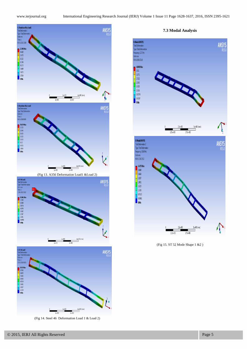
(Fig 13. A356 Deformation Load1 &Load 2)
(Fig 14. Steel 46 Deformation Load 1 & Load 2)
7.3 Modal Analysis
(Fig 15. ST 52 Mode Shape 1 &2 )

www.ierjournal.org International Engineering Research Journal (IERJ) Volume 1 Issue 11 Page 1628-1637, 2016, ISSN 2395-1621
© 2015, IERJ All Rights Reserved Page 6
(Fig 16. ST 52 Mode Shape 3 & 4)
(Fig 17. ST 52 Mode Shape 5 & 6)

www.ierjournal.org International Engineering Research Journal (IERJ) Volume 1 Issue 11 Page 1628-1637, 2016, ISSN 2395-1621
© 2015, IERJ All Rights Reserved Page 7
Fig 18. A356 Mode Shape 1 & 2
Fig 19. A356 Mode Shape 3 & 4

www.ierjournal.org International Engineering Research Journal (IERJ) Volume 1 Issue 11 Page 1628-1637, 2016, ISSN 2395-1621
© 2015, IERJ All Rights Reserved Page 8
Fig 20. A356 Mode Shape 5 & 6
Fig 21. Steel 46 Mode Shape 1& 2

www.ierjournal.org International Engineering Research Journal (IERJ) Volume 1 Issue 11 Page 1628-1637, 2016, ISSN 2395-1621
© 2015, IERJ All Rights Reserved Page 9
Fig 22. Steel 46 Mode Shape 3 & 4
Fig 23. Steel 46 Mode Shape 5 & 6
VIII. RESULT
(Table No.3 Result for Load 1 & 2)
IX.CONCLUSION
From the above results the optimum material use for the
Generic chassis is Steel 52. Even though the Von misses
stress for Steel 52 is greater than Aluminum alloy, but the
deflection for steel 52 which is lowest among three
materials.
REFRENCES
[1] Tushar M. Patel, Dr. M. G. Bhatt ,Harshad K. Patel “
Parametric Optimization of Eicher 11.10 Chassis Frame for
Weight Reduction Using FEA-DOE Hybrid Modeling” Iosr
Journal of Mechanical and Civil Engineering (IOSR-JMCE)
e-ISSN: 2278-1684,p-ISSN: 2320-334X, Volume 6, Issue 2
(Mar. - Apr. 2013), PP 92-100
Load 1 Load 2
Sr.
No.
Material Von Misses Stress
MPa
Deflection
mm
Von Misses Stress
MPa
Deflection
mm
1 Steel 52 175.94 7.91 234.7 10.55
2 Aluminum Alloy 174.66 22.98 232.99 30.65
3 Steel 46 177.99 8.18 237.94 10.92

www.ierjournal.org International Engineering Research Journal (IERJ) Volume 1 Issue 11 Page 1628-1637, 2016, ISSN 2395-1621
© 2015, IERJ All Rights Reserved Page 10
[2] Tushar M. Patel, Dr. M. G. Bhatt, Harshad K. Patel
“Analysis and validation of Eicher 11.10 chassis frame
using Ansys” International Journal of Emerging Trends &
Technology in Computer Science (IJETTCS)ISSN2278-
6856, Volume 2, Issue 2, March-April 2013.
[3] Swami K.I, Prof. Tuljapure S.B. “ Analysis of Ladder
Chassis of Eicher 20.16 Using FEM” IOSR Journal of
Applied Geology and Geophysics (IOSR-JAGG) e-ISSN:
2321–0990, p-ISSN: 2321–0982.Volume 2, Issue 1 Ver. I.
(Jan. 2014), PP 06-13
[4] Salvi Gauri Sanjay, Kulkarni Abhijeet 2, Gandhi Pratik
Pradeep, Baskar P. “Finite Element Analysis of Fire Truck
Chassis for Steel and Carbon Fiber Materials” Salvi Gauri
Sanjay et al Int. Journal of Engineering Research and
Applications ISSN : 2248-9622, Vol. 4, Issue 7 ( Version 2),
July 2014, pp.69-74
[5] Sairam Kotari ,V.Gopinath “Static And Dynamic
Analysis On Tatra Chassis” International Journal of Modern
Engineering Research (IJMER) Vol.2, Issue.1, pp-086-094
ISSN: 2249-6645
[6] AIS-052(Rev.1) standard . (www.araiindia.com).


