Embed Size (px)
Citation preview
N A S A TECHNICAL NOTE
ISOTHERMAL ELASTOHYDRODYNAMIC LUBRICATION OF POINT CONTACTS I11 - Fully Flooded Results
I Bernard J. Hamrock and Duncan Dowson
Lewis Research Center Cleveland, Ohio 44135
https://ntrs.nasa.gov/search.jsp?R=19770004457 2020-04-10T04:58:40+00:00Z
TECH LIBRARY KAFB, NM
O F POINT CONTACTS Ill - FULLY FLOODED RESULTS
. .
7. Author(s) Bernard J. Hamrock of the Lewis Research Center; and Duncan Dowson of the University of Leeds
Lewis Research-Center National Aeronautics and Space Administration
~
9. Performing Organization Name and Address
Cleveland, Ohio 441 3 5 2. Sponsoring Agency Name and Address
~~
National Aeronautics and Space Administration Washington, D.C. 20546
I Illill 11111 lllll lllll lllll lllll lllll Ill1 Ill
6. Performing Organization Code
8. Performing Organization Report No.
E-8712 10. Work Unit No.
505-04 11. Contract or Grant No.
13. Type of Report and Period Covered
Technical Note 14. Sponsoring Agency Code
9. Security Classif (of this report)
Unclassified
I 5. Supplementary Notes
20. Security Classif. (of this page) 1 21 . ~ 0 . ~ 0 ; pages 22. Price'
Unclassified $4.00
6. Abstract
The theory developed by the authors in an earlier publication was used to investigate the influ- ence of the ellipticity parameter and the dimensionless speed U, load W, and material G pa- rameters on minimum film thickness. The ellipticity parameter k was varied f rom l (a ball- on-plate configuration) to 8 (a configuration approaching a line contact). speed parameter was varied over a range of nearly two orders of magnitude. And the dimen- sionless load parameter was varied over a range of one order of magnitude. Conditions cor- responding to the use of solid materials of bronze, steel, and silicon nitride and lubricants of paraffinic and naphthenic mineral oils were considered in obtaining the exponent on the dimen- sionless material param5ter. Thirty-four different cases were used in obtaining the minimum- film-thickness formula Hmin = 3.63 U'. 68Go' 49W-0* 073 (1 - e -" 68k). A simplified expression
'* 64 can be written, where R /Rx is the radius for the ellipticity parameter k = 1.03 (R /Rx) of curvature ratio. Contour plots are also shown that indicate in detail the pressure spike and the two s ide lobes in which the minimum f i lm thickness occurs. These theoretical solutions of film thickness have all the essential features of previously reported experimental observations based upon optical interferometry.
The dimensionless
Y Y
7. Key Words (Suggested by Author(sJJ
Elastohydrodynamics Lubrication Bearings Gears Q
~. ~
18. Distribution Statement
Unclassified - unlimited STAR Category 37
ISOTHERMAL ELASTOHYDRODYNAMIC LUBRICATION OF POINT CONTACTS
111 - FULLY FLOODED RESULTS*
by Bernard J. Hamrock and D u n c a n Dowsont
Lewis Research Center
SUMMARY
The theory developed by the authors in an ear l ier publication was used to investigate the influence of the ellipticity parameter and the dimensionless speed U, load W, and material parameters on minimum film thickness. from 1 (a ball-on-plate configuration) to 8 (a configuration approaching a line contact). The dimensionless speed parameter was varied over a range of nearly two orders of magnitude. And the dimensionless load parameter was varied over a range of one order of magnitude. Conditions corresponding to the use of solid materials of bronze, steel, and silicon nitride and lubricants of paraffinic and naphthenic mineral oils were consid- ered in obtaining the exponent on the dimensionless material parameter. different cases were used in obtaining the minimum -film-thickness formula
The ellipticity parameter w a s varied
Thirty-four
1 N 0.68 0. 49w-0.073(1 - e -0.68k Hmin = 3.63 U G
A simplified expression for the ellipticity parameter k was found, where
R /Rx being the radius of curvature ratio. Contour plots are also shown that indicate in detail the pressure spike and the two
side lobes in which the minimum film thickness occurs. These theoretical solutions of film thickness have all the essential features of previously reported experimental ob- servations based upon optical interferometry.
Y
*Presented at Joint Lubrication Conference cosponsored by the American Society of Mechanical Engineers and the American Society of Lubrication Engineers, Boston, Mas- sachusetts, October 5-7, 1976.
'Professor of Mechanical Engineering, University of Leeds, Leeds, England.
I I I I I 1 I 11111111l1ll11111llllII I Ill1
INTRODUCTION
Only in recent years has the complete theoretical solution of the isothermal elasto- hydrodynamic lubrication (EHL) of point contacts been successfully analyzed. The anal- ysis requires the simultaneous solution of the elasticity and Reynolds equations. The authors' approach to the theoretical solution has been presented in two previous publica- tions (refs. 1 and 2). The first of these publications (ref. 1) presents the elasticity model in which the conjunction is divided into equal rectangular areas with a uniform pressure applied over each area. The second (ref. 2) gives the complete approach to solving the elastohydrodynamic lubrication problem for point contacts.
The most important practical aspect of the EHL point-contact theory (ref. 2) is the determination of the minimum film thickness within the contact. That is, maintaining a fluid film thickness of adequate magnitude is extremely important to the operation of some machine elements. In the present report , only the resul ts from the theory given in references 1 and 2 a r e presented. In the results the influence of contact geometry as expressed in the ellipticity parameter and the dimensionless speed, load, and material parameters on minimum film thickness is investigated for a conjunction fully immersed in lubricant (i. e. , fully flooded). The ell ipticih resul ts have been presented in refer- ence 3 by the authors, but in the present report additional solutions a r e presented and the accuracy of the presentation is improved. The corrected ellipticity results a r e pre- sented in this report . In the numerical work the ellipticity parameter was varied from 1 (a ball-on-plate configuration) to 8 (a configuration approaching a line contact). The dimensionless speed and load parameters were varied over ranges of about two and one orders of magnitude, respectively. Conditions equivalent to using solid materials of bronze, steel, and silicon nitride and lubricants of paraffinic and naphthenic mineral oils were considered in obtaining the exponent on the dimensionless material parameter. Thirty-four different cases were used in obtaining the fully flooded film-thickness for- mulas. A fully flooded condition is said to exist when the inlet distance of the conjunc- tion ceases to influence, in any significant way, the minimum film thickness. The inlet distance of the conjunction is defined as the distance from the center of the contact to the edge of the computing area. Contour plots a r e also shown that indicate in detail the pressure spike and the two s ide lobes in which the minimum film thickness occurs.
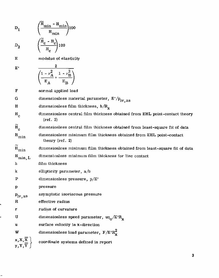
SYMBOLS
a
b
semimajor axis of contact ellipse
semiminor axis of contact ellipse
2
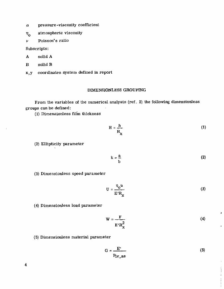
Dl
D2
E
E'
F
G
H
HC
N
Hmin
N
Hmin
Hmin, L h
k
P
P
Piv, as R
r
U
modulus of elasticity
2 1 - " * 2 1 - v g
(T+ EB2)
normal applied load
dimensionless material parameter, E'/piV, as
dimensionless film thickne ss , h/Rx
dimensionless central film thickness obtained from (ref. 2)
dimensionless central film thickness obtained from
EHL point-contact
least-square fit of
theory
data
dimensionless minimum film thickness obtained from EHL point-contact theory (ref. 2)
dimensionless minimum film thickness obtained from least-square f i t of data
dimensionless minimum film thickness for line contact
film thickness
ellipticity parameter, a/b dimensionless pressure, p/E'
pressure
asymptotic isoviscous pressure
effective radius
radius of curvature
dimensionless speed parameter, uqo/13'Rx
surface velocity in x-direction 2 dimensionless load parameter, F/E'R,
coordinate systems defined in report
3
(Y pressure -viscosity coefficient
qo atmospheric viscosity
v Poisson's ratio
Subscripts:
A solid A
B solid B
x , y coordinates system defined in report
DIMENSIONLESS GROUPING
From the variables of the numerical analysis (ref. 2) the following dimensionless
(1) Dimensionless film thickness groups can be defined:
(2) Ellipticity parameter
(3) Dimensionless speed parameter
a b
k = -
(4) Dimensionless load parameter
E'Rx 2
(5) Dimensionless material parameter
I
(4)
4
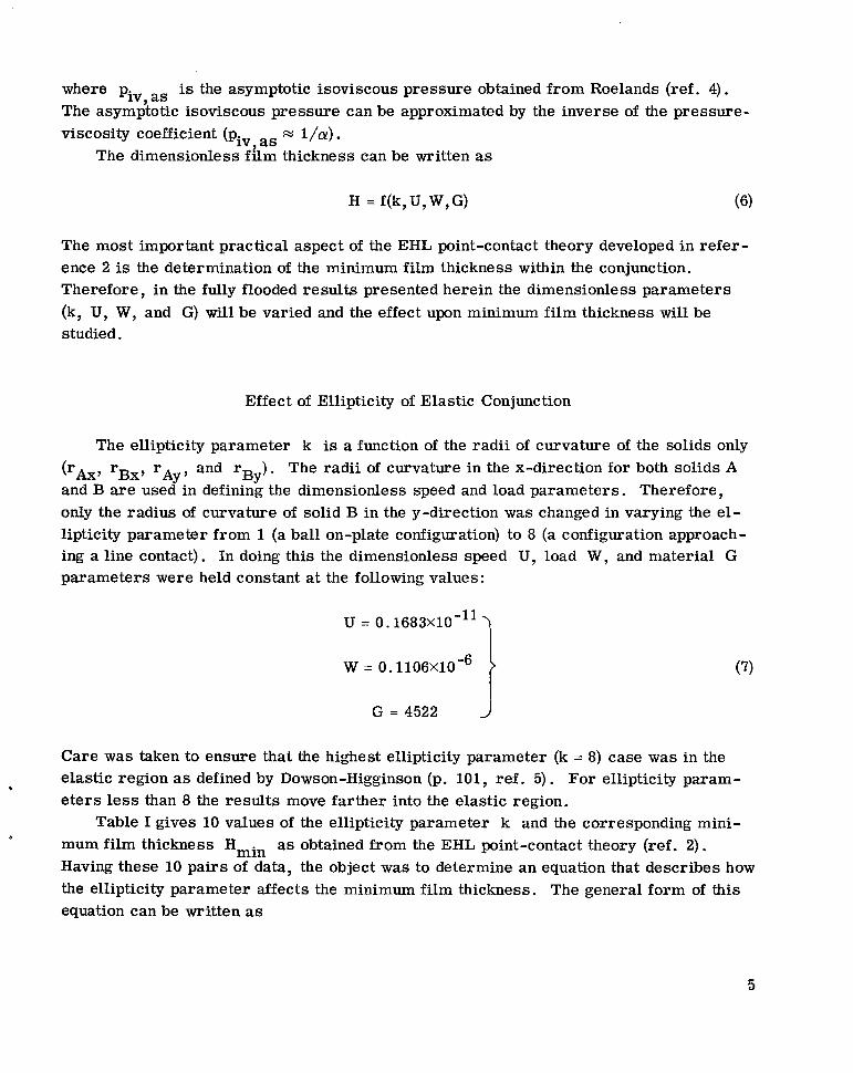
where ~ i v , as is the asymptotic isoviscous pressure obtained from Roelands (ref. 4). The asymptotic isoviscous pressure can be approximated by the inverse of the pressure- viscosity coefficient (piv, as = l/a) -
The dimensionless film thickness can be written as
H = f(k,U,W,G) (6)
The most important practical aspect of the EHL point-contact theory developed in refer- ence 2 is the determination of the minimum film thickness within the conjunction. Therefore, in the fully flooded resul ts presented herein the dimensionless parameters (k, U, W, and G) will be varied and the effect upon minimum film thickness will be studied.
Effect of Ellipticity of Elastic Conjunction
The ellipticity parameter k is a function of the radii of curvature of the solids only (rAx, rBx, rAy, and r ) . The radii of curvature in the x-direction for both solids A and B a r e used in defining the dimensionless speed and load parameters. Therefore, only the radius of curvature of solid B in the y-direction was changed in varying the el- lipticity parameter from l (a ball on-plate configuration) to 8 (a configuration approach- ing a line contact). In doing this the dimensionless speed U, load W, and material G parameters were held constant at the following values:
BY
U = 0. 1683X10'11 1 W = 0.1106X10⁻⁶
G = 4522 J
Care was taken to ensure that the highest ellipticity parameter (k = 8) case was in the elastic region as defined by Dowson-Higginson (p. 101, ref. 5). For ellipticity param- eters less than 8 the results move farther into the elastic region.
Table I gives 10 values of the ellipticity parameter k and the corresponding mini- mum film thickness Hmin as obtained from the EHL point-contact theory (ref. 2). Having these 10 pairs of data, the object was to determine an equation that describes how the ellipticity parameter affects the minimum film thickness. The general form of this equation can be written as
.
5
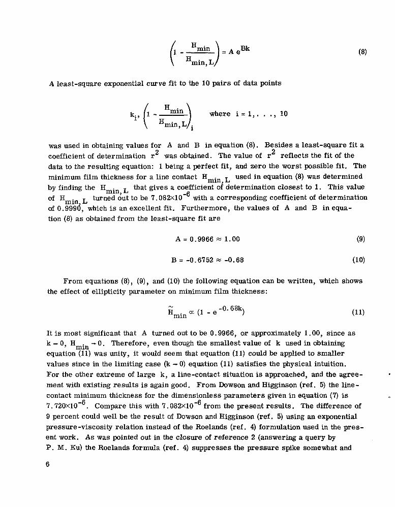
(1 - H z : L ) = A e Bk
A least-square exponential curve fit to the 10 pairs of data points
ki, (1 - Hmin)i where i = 1,. . ., 10 Hmin, L
was used in obtaining values for A and B in equation (8). Besides a least-square f i t a coefficient of determination r2 was obtained. The value of r2 reflects the fi t of the data to the resulting equation: 1 being a perfect f i t , and zero the worst possible f i t . The minimum film thickness for a line contact Hmin used in equation (8) was determined by finding the Hmin,L that gives a coefficient o# determination closest to 1. This value
of Hmin L of 0.999d, which is an excellent fi t . Furthermore, the values of A and B in equa- tion (8) a s obtained from the least-square fit are
turned out to be 7 . 0 8 2 ~ 1 0 - ~ with a corresponding coefficient of determination
A = 0.9966 1.00 (9)
B = -0.6752 M -0.68 (10)
From equations (8), (9), and (10) the following equation can be written, which shows the effect of ellipticity parameter on minimum film thickness:
N -0.68k) Hmin a (1 - e
It is most significant that A turned out to be 0.9966, or approximately 1.00, since a s k - 0, Hmin - 0. Therefore, even though the smallest value of k used in obtaining equation (11) was unity, it would seem that equation (11) could be applied to smaller values since in the limiting case (k - 0) equation (11) satisfies the physical intuition. For the other extreme of large k, a line-contact situation is approached, and the agree- ment with existing results is again good. From Dowson and Higginson (ref. 5) the line- contact minimum thickness for the dimensionless parameters given in equation (7) is 7.720X10⁻⁶. Compare this with 7. 082X10-6 from the present results. The difference of 9 percent could well be the result of Dowson and Higginson (ref. 5) using an exponential pressure-viscosity relation instead of the Roelands (ref. 4) formulation used in the pres- ent work. A s was pointed out in the closure of reference 2 (answering a query by P. M. Ku) the Roelands formula (ref. 4) suppresses the pressure spike somewhat and
0
6
N also results in a smaller film thickness.
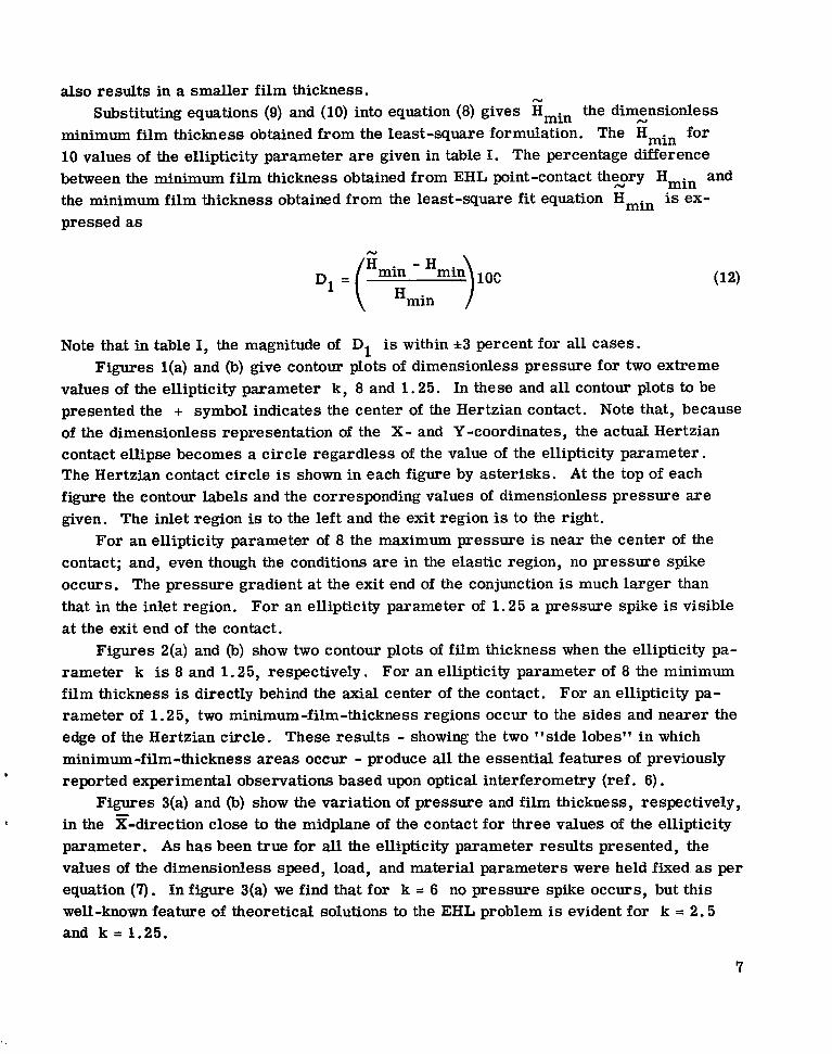
minimum film thickness obtained from the least-square formulation. The Hmin for 10 values of the ellipticity parameter a r e given in table I. The percentage difference between the minimum film thickness obtained from EHL point-contact th%ory Hmin and the minimum film thickness obtained from the least-square f i t equation Hmin is ex- pressed as
Substituting equations (9) and (10) into equation (8) gives Hmin the dimensionless N
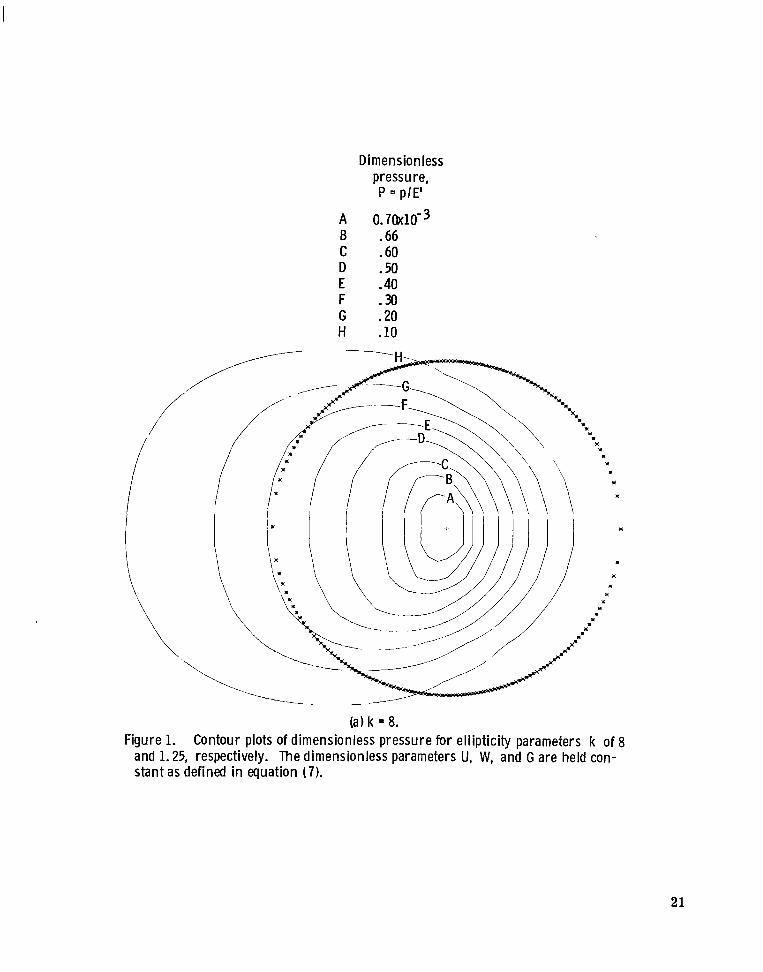
Note that in table I, the magnitude of D1 is within 2~3 percent for all cases. Figures l(a) and (b) give contour plots of dimensionless pressure for two extreme
values of the ellipticity parameter k, 8 and 1.25. In these and all contour plots to be presented the + symbol indicates the center of the Hertzian contact. Note that, because of the dimensionless representation of the X- and Y-coordinates, the actual Hertzian contact ellipse becomes a circle regardless of the value of the ellipticity parameter. The Hertzian contact circle is shown in each figure by asterisks. A t the top of each figure the contour labels and the corresponding values of dimensionless pressure a r e given. The inlet region is to the left and the exit region is to the right.
For an ellipticity parameter of 8 the maximum pressure is near the center of the contact; and, even though the conditions a re in the elastic region, no pressure spike occurs. The pressure gradient at the exit end of the conjunction is much larger than that in the inlet region. For an ellipticity parameter of 1.25 a pressure spike is visible a t the exit end of the contact.
Figures 2(a) and (b) show two contour plots of film thickness when the ellipticity pa- rameter k is 8 and 1.25, respectively. For an ellipticity parameter of 8 the minimum film thickness is directly behind the axial center of the contact. For an ellipticity pa- rameter of l. 25, two minimum-film-thickness regions occur to the sides and nearer the edge of the Hertzian circle. These results - showing the two "side lobes" in which minimum-film-thickness a reas occur - produce all the essential features of previously reported experimental observations based upon optical interferometry (ref. 6).
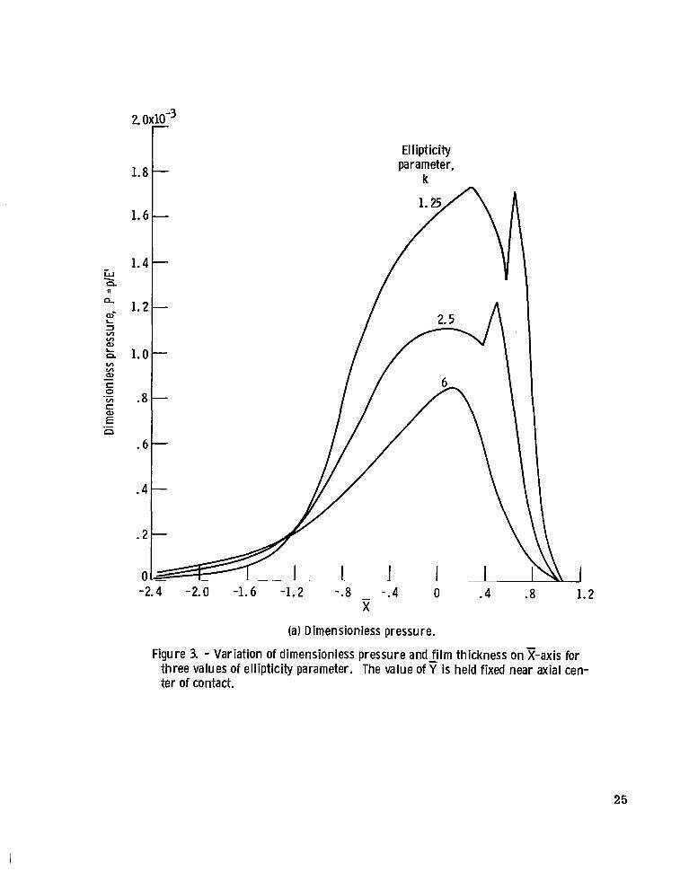
in the z-direction close to the midplane of the contact for three values of the ellipticity parameter. A s has been true for all the ellipticity parameter results presented, the values of the dimensionless speed, load, and material parameters were held fixed as per equation (7). In figure 3(a) we find that for k = 6 no pressure spike occurs, but this well-known feature of theoretical solutions to the EHL problem is evident for k = 2.5 and k = 1.25.
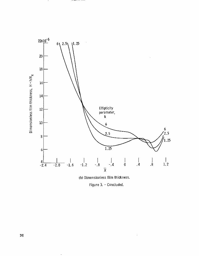
. Figures 3(a) and (b) show the variation of pressure and film thickness, respectively,
7

In figure 3(b) for k = 1.25 the central region is not parallel with the z-axis. The reason is probably that compressibility effects are considered in the theory (ref. 2). That is, when compressibility is considered, the film thickness in the center is reduced by the amount that the fluid volume decreases at high pressure (ref. 5).
INFLUENCE OF SPEED
By changing only the surface velocity in the x-direction u, the dimensionless speed parameter U (eq. (3)) changes, but the other dimensionless parameters (k, W, and G) remain constant. The values at which these dimensionless parameters were held con- stant in the calculations are
W = 0 . 7 3 7 1 ~ 1 0 - ~
i G = 4522
k = 6
Table 11 gives the dimensionless speed parameter U and the corresponding mini- mum film thickness Hmin as obtained from the EHL point-contact theory (ref. 2). There are 15 different values of the dimensionless speed parameter covering nearly two orders of magnitude. Having these 15 pairs of data, the objective is to determine an equation that describes how the dimensionless speed affects the minimum film thickness. The general form of this equation can be written as
Hmin = IUJ
By applying a least-square power fit to the 15 pairs of data (Vi, Hmin,i, where i = 1, . . . , 15) the values of I and J were found to be
I = 560.18 (15)
J = 0.67542 E 0.68
The coefficient of determination r2 for these results was excellent at 0.9998. Substitut- ing equations (15) and (16) into equation (14) gives the values of amin shown in table II. The percentage difference D1 between the minimum film thickness obtained from the EHL point-contact theory Hmin and the minimum film thickness obtained from the least-square f i t Hmin is expressed in equation (12) and given in table II. Note that the
8
(16)
N
- .. .
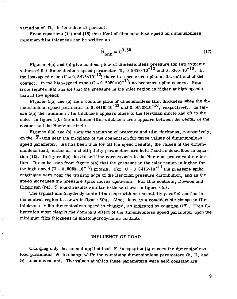
variation of D1 is less than i 2 percent.
minimum film thickness can be written as From equations (14) and (16) the effect of dimensionless speed on dimensionless
N
H~~~ a ~ 0 . 6 ~
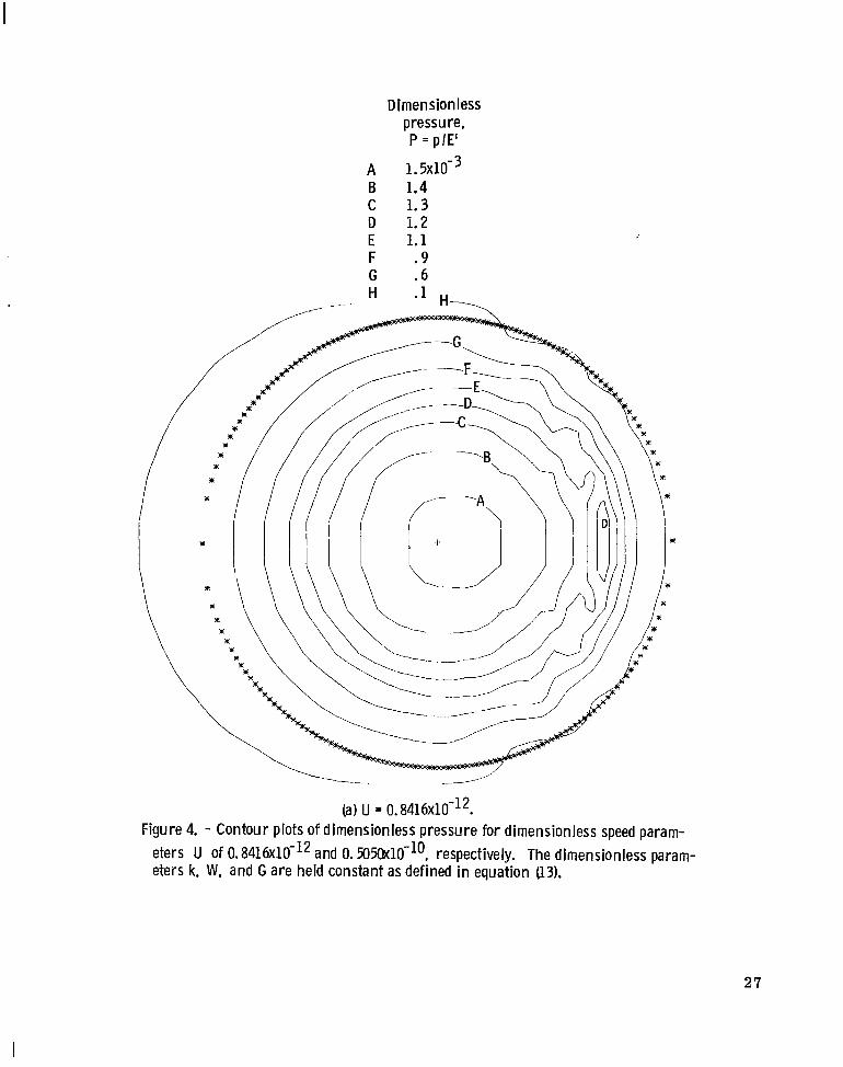
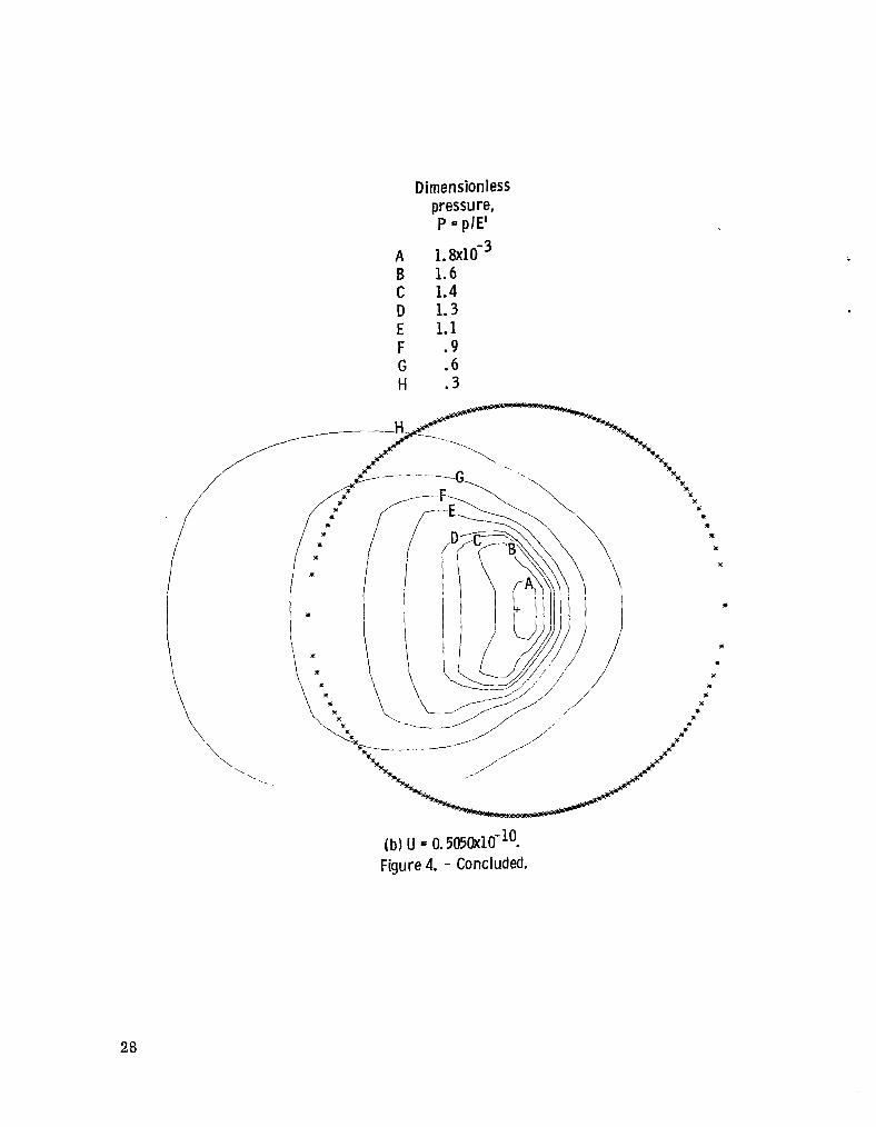
Figures 4(a) and (b) give contour plots of dimensionless pressure for two extreme values of the dimensionless speed parameter U, 0 . 8 4 1 6 ~ 1 0 ' ~ ~ and 0 . 5 0 5 0 ~ 1 0 - ~ ~ . In the low-speed case (U = 0.8416x10⁻¹²) there is a pressure spike at the exit end of the contact. In the high-speed case (U = 0 . 5 0 5 0 ~ 1 0 - ~ ~ ) no pressure spike occurs. Note from figures 4(a) and (b) that the pressure in the inlet region is higher at high speeds than at low speeds.
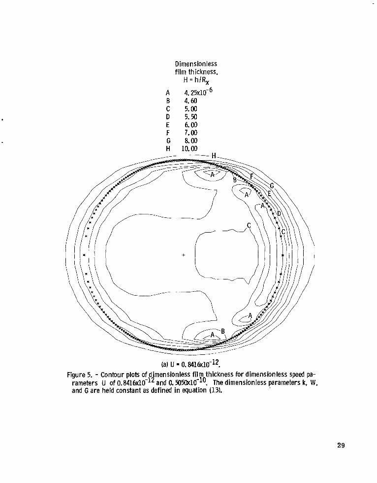
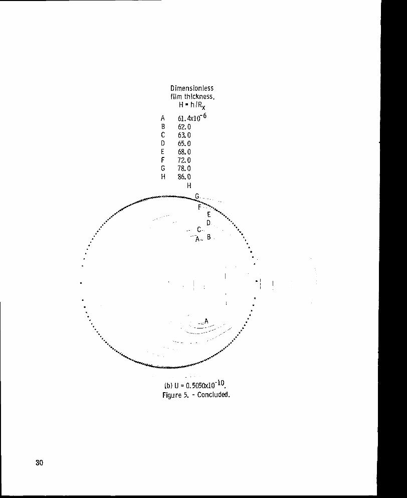
mensionless speed parameter is 0 . 8 4 1 6 ~ 1 0 ' ~ ~ and 0. 5050X10-10, respectively. In fig- ure 5(a) the minimum film thickness appears close to the Hertzian circle and off to the side. In figure 5(b) the minimum -film-thickness area appears between the center of the contact and the Hertzian circle.
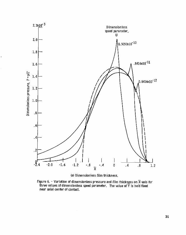
Figures 6(a) and (b) show the variation of pressure and film thickness, respectively, on the x-axis near the midplane of the conjunction for three values of dimensionless speed parameter. A s has been true for all the speed results, the values of the dimen- sionless load, material, and ellipticity parameters are held fixed as described in equa- tion (13). In figure 6(a) the dashed line corresponds to the Hertzian pressure distribu- tion. It can be seen from figure 6(a) that the pressure in the inlet region is higher for the high speed (U = 0 . 5 0 5 0 ~ 1 0 ' ~ ~ ) profile. For U = 0 . 8 4 1 6 ~ 1 0 - ~ ~ the pressure spike originates very near the trailing edge of the Hertzian pressure distribution, and as the speed increases the pressure spike moves upstream. For line contacts, Dowson and Higginson (ref. 5) found results similar to those shown in figure 6(a) .
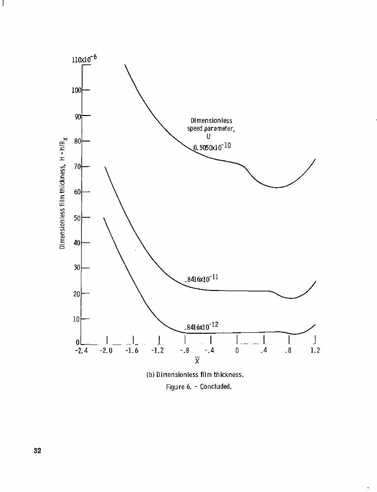
The typical elastohydrodynamic film shape with an essentially parallel section in the central region is shown in figure 6(b). Also, there is a considerable change in film thickness as the dimensionless speed is changed, as indicated by equation (17). This il- lustrates most clearly,the dominant effect of the dimensionless speed parameter upon the
Figures 5(a) and (b) show contour plots of dimensionless film thickness when the di-
, minimum film thickness in elastohydrodynamic contacts.
t
INFLUENCE OF LOAD
Changing only the normal applied load F in equation (4) causes the dimensionless load parameter W to change while the remaining dimensionless parameters (k, U, and G) remain constant. The values at which these parameters were held constant are
9
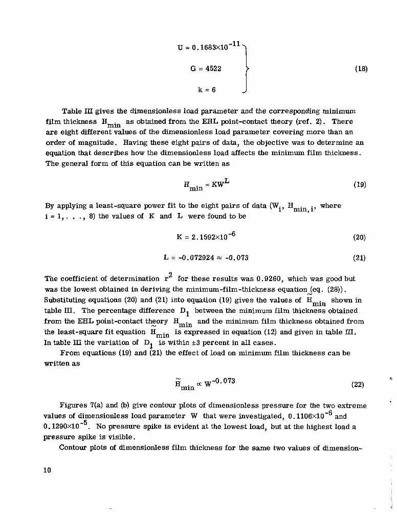
U = 0. 1683X10-11 1 G = 4522
k = 6
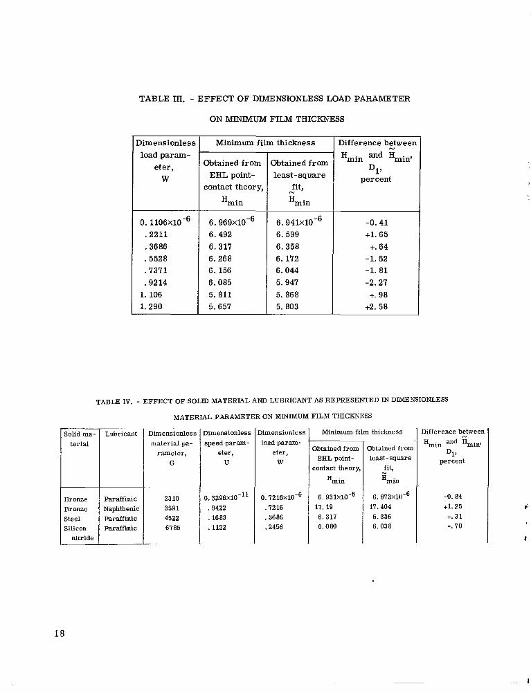
Table III gives the dimensionless load parameter and the corresponding minimum film thickness Hmin as obtained f rom the EHL point-contact theory (ref. 2). There are eight different values of the dimensionless load parameter covering more than an order of magnitude. Having these eight pairs of data, the objective was to determine an equation that describes how the dimensionless load affects the minimum film thickness. The general form of this equation can be written as
L Hmin = KW
By applying a least-square power fit to the eight pairs of data (Wi, Hmin,i, where i = 1 , . . . , 8) the values of K and L were found to be
K = 2. 1592X10-6 (20)
L = -0.072924 w -0,073 (2 1)
The coefficient of determination r2 for these results was 0.9260, which was good but was the lowest obtained in deriving the minimum-film-thickness equation (eq. (28)). Substituting equations (20) and (21) into equation (19) gives the values of Hmin shown in table III. The percentage difference D1 between the minimum film thickness obtained from the EHL point-contact theory Hmin and the minimum film thickness obtained from the least-square fit equation Hmin is expressed in equation (12) and given in table III. In table 111 the variation of D1 is within &3 percent in all cases.
written as
N
N
From equations (19) and (21) the effect of load on minimum film thickness can be
N cc w-0.073 Hmin
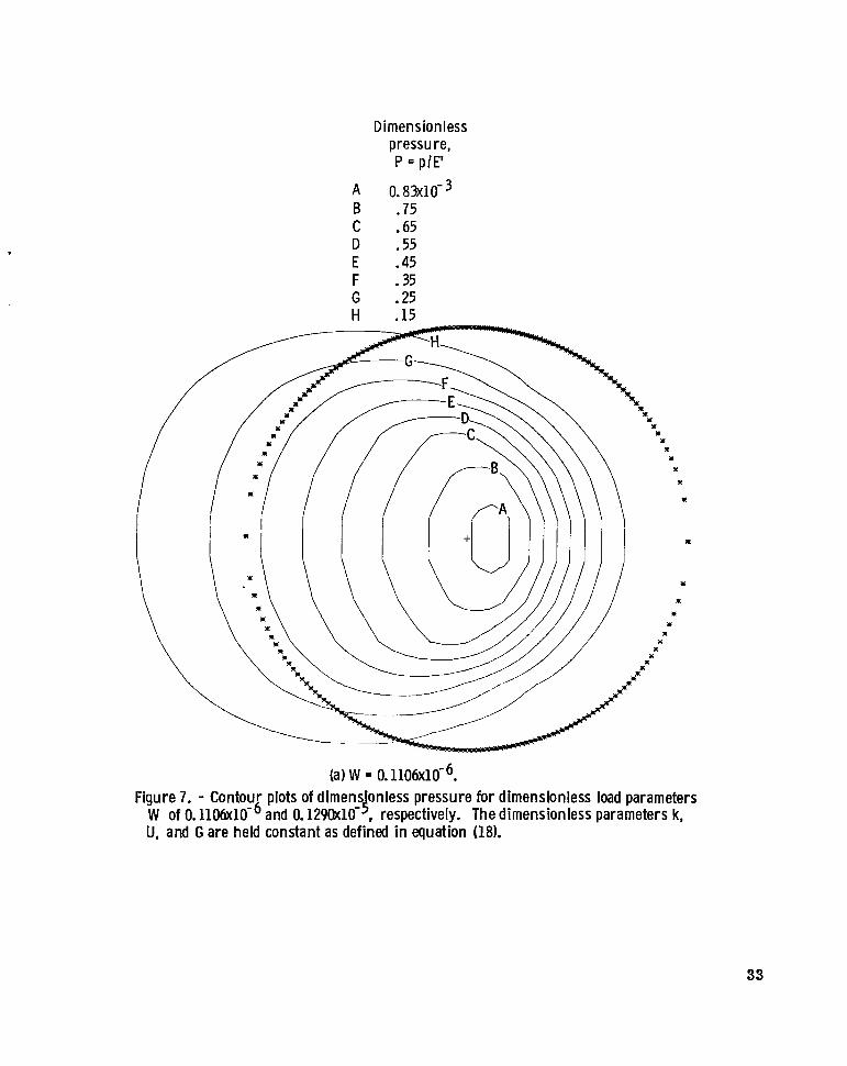
Figures 7(a) and (b) give contour plots of dimensionless pressure for the two extreme 4
values of dimensionless load parameter W that were investigated, 0. 1106X10-6 and 0 . 1 2 9 0 ~ 1 0 - ~ . No pressure spike is evident at the lowest load, but at the highest load a pressure spike is visible.
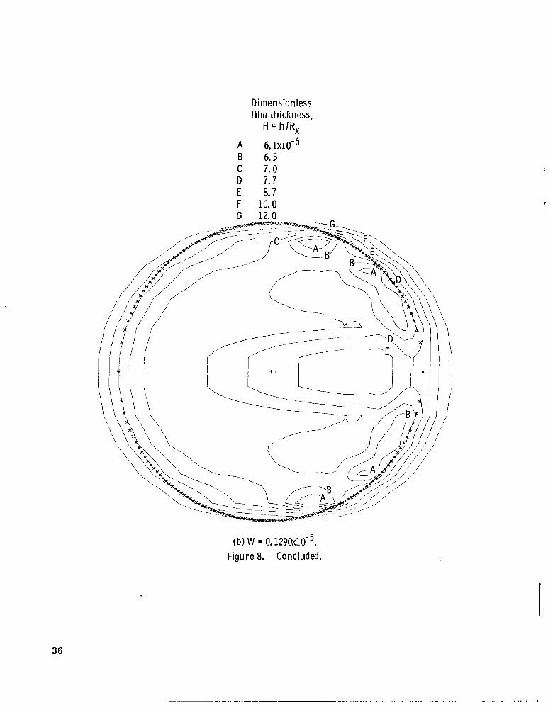
Contour plots of dimensionless film thickness for the same two values of dimension-
10

less load parameter as given in figure 7 are shown in figure 8. In figure 8(a) for the low-load case (W = 0. 1106X10-6) the minimum film thickness occurs directly behind the center of the contact. In figure 8(b) for the high-load case (W = 0.129OXlO-5) the mini- mum film thickness is off to the sides in two areas close to the Hertzian circle.
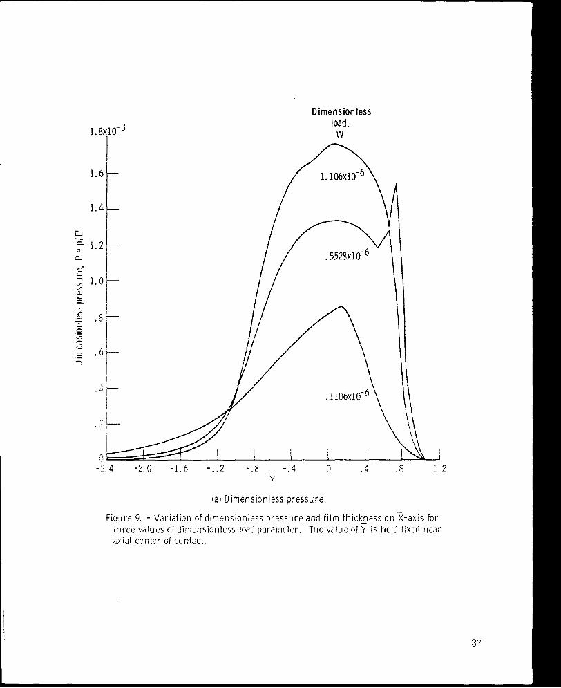
The variation of pressure and film thickness in the z-direction along a line close to the midplane of the conjunction is shown in figure 9 for three values of the dimensionless load parameter. The values of the dimensionless speed, material, and ellipticity pa- rameters were held fixed as described by equation (18) for all computations at various loads. In figure 9(a) as the dimensionless load is increased the inlet pressure becomes smaller. For the highest load case shown in figure 9(b), film thickness rises between the central region and the outlet restriction in the same manner as seen in figure 3(b). Again this is attributed to the compressibility effects of the fluid. Also, at a load W of 0. 5528X10-6 the film thickness is slightly smaller than at a W of 1. 106X10'6. The reason is that the minimum film thickness is closer to the axial center of the contact at the lower load than at the higher load. A s was pointed out in discussing figures 8(a) and (b) , the location of the minimum-film-thickness region changes as the dimensionless load is changed.
EFFECT OF MATERIAL PROPERTLES
The effect of the dimensionless material parameter on minimum film thickness is not a simple matter. A s can be seen from equations (3), (4), and (5), when either the material of the solids (as expressed in E') o r the material of the lubricant (as expressed in 7, and piv,as) is varied, not only does the material parameter G change, but so do the dimensionless speed U and load W parameters. Only the ellipticity parameter can be held fixed. For all the results presented in this section the ellipticity parameter is held fixed at 6.
the minimum film thickness is a function of the dimensionless material parameter is given as
Table IV gives the four material-parameter results. The general form showing how
W
# where
(23) V C = TG
C = Hmin (1 - e -0. 68klU0. 6%-0.073
(24)
11
In equation (24) the exponents are rounded off to two significant figures so that any error could be absorbed in T given in equation (23). By applying a least-square power fit to the four pairs of data, the values of T and V were found to be
T = 3.6891 (2 5)
V = 0.48669 0.49 (26)
The coefficient of determination for these resul ts was 0.9980, which is excellent. Sub- stituting equations (25) and (26) into equation (23) gives the values of Emin shown in ta- ble IV. The percentage difference D1 shown in table IV varies by l e s s than 2 percent in all cases. Therefore, from equations (23) and (25) the effect of the dimensionless ma- terial parameter on the dimensionless film thickness can be written as
N
H~~~ a GO. 49
MINIMUM -FII,M-THICKNESS FORMULA
The proportionality expressions (ll), (17), (22), and (27) established how the mini- mum film thickness varies with the ellipticity, speed, load, and material parameters, respectively. This enables a composite minimum-film-thickness formula for a fully flooded, isothermal, elastohydrodynamic point contact to be written as
N 0.68GO. 4gW-0. 073 (1 - e -0.68k) Hmin = 3.63 U
In equation (28) the constant 3.63 is different from that in equation (25) to account for rounding off the material-parameter exponent.
Table V gives the 34 different cases used in obtaining equation (28). In this table, corresponds to the minimum film N thickness obtained from the EHL point-contact Hmin
theory developed in reference 2, and Hmin is the minimum film thickness obtained from equation (28). The percentage difference between these two values is expressed by D1, which is defined in equation (12). In table V the values of D1 are within k5 percent.
It is sometimes more convenient to express the side-leakage factor in equation (28) in terms of the radius of curvature ratio R /'R instead of the ellipticity parameter k
Y X through the following relation:
m
t
12
where
1 +- 1 - 1 - _ - Ry 'Ay rBy
1 - 1 1 ---+- Rx 'Ax 'Bx
Using equation (29) avoids the need to evaluate elliptic integrals of the first and second kinds in the determination of k. The minimum film thickness can thus be derived di- rectly from a knowledge of the radii of curvature of the contacting bodies (rAx, rBx, rAy, and rBy).
It is interesting to compare the new, point-contact, minimum-film-thickness for- mula (eq. (28)) with the corresponding equation generated in the 1960's (ref. 7) for line contacts
Hmin, = 2.65 U 0.70GO. 5%-0.13
The powers of U, G, and W in equations (28) and (32) are quite similar considering the iiifferent numerical procedures upon which they are based. It is also worth noting that the power of W in equation (28) is extremely close to the value of -0.074 proposed by Archard and Cowking in their study of point contacts (ref. 8).
CENTRAL-FILM-THICKNESS FORMULA
There is interest in knowning the central film thickness, in addition to the minimum 'ilm thickness, in elastohydrodynamic contacts. The procedure used in obtaining the :entral film thickness was the same as that used in obtaining the minimum film thickness tnd is not repeated here. The central-film-thickness formula obtained from the resul ts .s
?
(33) Hc N = 2.69 U 0.6760. 53w-0. 067(1 - 0. 61 e-o- 73k)
&
Comparing the central-film-thickness formula (eq. (33)) with the minimum-film- thickness formula (eq. (28)) reveals a slight difference. In equation (33) the load expo- nent is small but negative, as it was for the minimum-film-thickness formula. This is in contrast with the recent numerical study of Ranger, et al. (ref. 9) who found a small but positive exponent on the dimensionless load W in their formulation of a central f i lm
13

thickness.
corresponds to the central film thickness obtained from the EHL point-contact theory developed in reference 2, and Hc corresponds to the central film thickness obtained from equation (33). The percentage difference between these two values is given by D2 and is written as
Table VI gives the 34 different cases used to obtain equation (33). In this table, Hc
N
In table VI the values of D2 are within i l 0 percent.
CONCLUDING REMARKS
By using the procedures outlined by the authors in an earlier publication the influ- ence of the ellipticity parameter and the dimensionless speed U, load W, and material G parameters on minimum film thickness has been investigated. The ellipticity param- eter was varied from 1 (a ball-on-plate configuration) to 8 (a configuration approaching a line contact). The dimensionless speed parameter was varied over a range of nearly two orders of magnitude. The dimensionless load parameter was varied over a range of one order of magnitude. Situations equivalent to using solid materials of bronze, steel, and silicon nitride and lubricants of paraffinic and naphthenic mineral oils were con- sidered in investigating the role of the dimensionless material parameter. Thirty-four different cases were used to generate the minimum-film-thickness and central-film- thickness relations:
Hmin N
= 3.63 u 0.68GO. 49w-O.O73(1 - e -0.68k)
It was found that the ellipticity parameter k can be written as
where R /R is the radius of curvature ratio. Y X
and the film thickness. In some solutions, pressure spikes were in evidence. The theo-
14
Contour plots have been presented that indicate in detail the pressure distribution
retical solutions of. film thickness have all the essential features of previously reported experimental observations based upon optical 'interferometry.
time a complete theoretical film-thickness equation for elastohydrodynamic point con- tacts operating under fully flooded conditions. The exponents on the various dimension- l e s s parameters governing minimum film thickness in such conjunctions are quite simi- lar to those developed earlier by Dowson for line contacts. The most dominant exponent occurs in association with the speed parameter, while the exponent on the load parameter is very small and negative. The material parameter also car r ies a significant exponent, although the range of this parameter in engineering situations is limited. A central- film-thickness formula exists for the contact geometry of a ball on a plate from which an estimate can be made of the minimum film thickness. However, the formula presented herein is valid for any contact geometry and proceeds directly to the evaluation of the minimum film thickness.
Perhaps the most significant feature of the proposed minimum-film-thickness for - mula is that it can be applied to any contacting solids that present an elliptical Hertzian contact region. Many machine elements, particularly rolling-element bearings, poss- e s s such geometry. And it is expected that the new minimum-film-thickness formula wi l l find application in such fields.
The importance of the present report lie's in the fact that it presents for the first
Lewis Research Center, National Aeronautics and Space Administration,
Cleveland, Ohio, July 28, 1976, 505-04.
REFERENCES
1. Hamrock, Bernard J. ; and Dowson, Duncan: Numerical Evaluation of the Surface Deformation of Elastic Solids Subjected to a Hertzian Contact Stress. NASA T N D-7774, 1974.
I L 2. Hamrock, Bernard J. ; and Dowson, Duncan: Isothermal Elastohydrodynamic Lubri- cation of Point Contacts. I - Theoretical Formulation. NASA TN D-8049, 1975;
' 8 also J. Lub. Tech. (Trans. ASME, ser . F), vol. 38, Apr. 1976, pp. 223-229.
3. Hamrock, Bernard J. ; and Dowson, Duncan: Isothermal Elastohydrodynamic Lubri- cation of Point Contacts. 11 - Ellipticity Parameter Results. NASA TN D-8166, 1976; also J. Lub. Tech. (Trans. ASME, ser. F), vol. 98, July 1976, pp. 375-383.
15
4. Roelands, C. J. A. : Correlational Aspects of the Viscosity-Temperature-Pressure Relationship of Lubricating Oils. Druk U. R. El., Groningen, The Netherlands, 1966.
5. Dowson, D. ; and Higginson, G. R. : Elastohydrodynamic Lubrication. Pergamon Press, 1966.
6. Cameron, A. ; and Gohar, R. : Theoretical and Experimental Studies of the Oil Film in Lubricated Point Contact. Proc. Royal SOC. (London), vol. 291A, no. 1427, Apr. 1966, pp. 520-536.
7. Dowson, D.: Elastohydrodynamics. Proc. Inst. Mech. Engrs., vol. 182, pt. 3A, 1968, pp. 151-167.
8. Archard, J. F. ; and Cowking, E . W. : Elastohydrodynamic Lubrication of Point Con- tacts. Proc. Inst. Mech. Engrs. , vol. 180, pt. 3B, 1965-1966, pp. 47-56.
9. Ranger , A. P. ; Ettles, C. M. M. ; and Cameron, A. : The Solution of the Point Con- tact Elasto-Hydrodynamic Problem. Proc . Royal Soc . (London), vol. 3468, no. 1645, Oct. 1975, pp. 227-244.
16
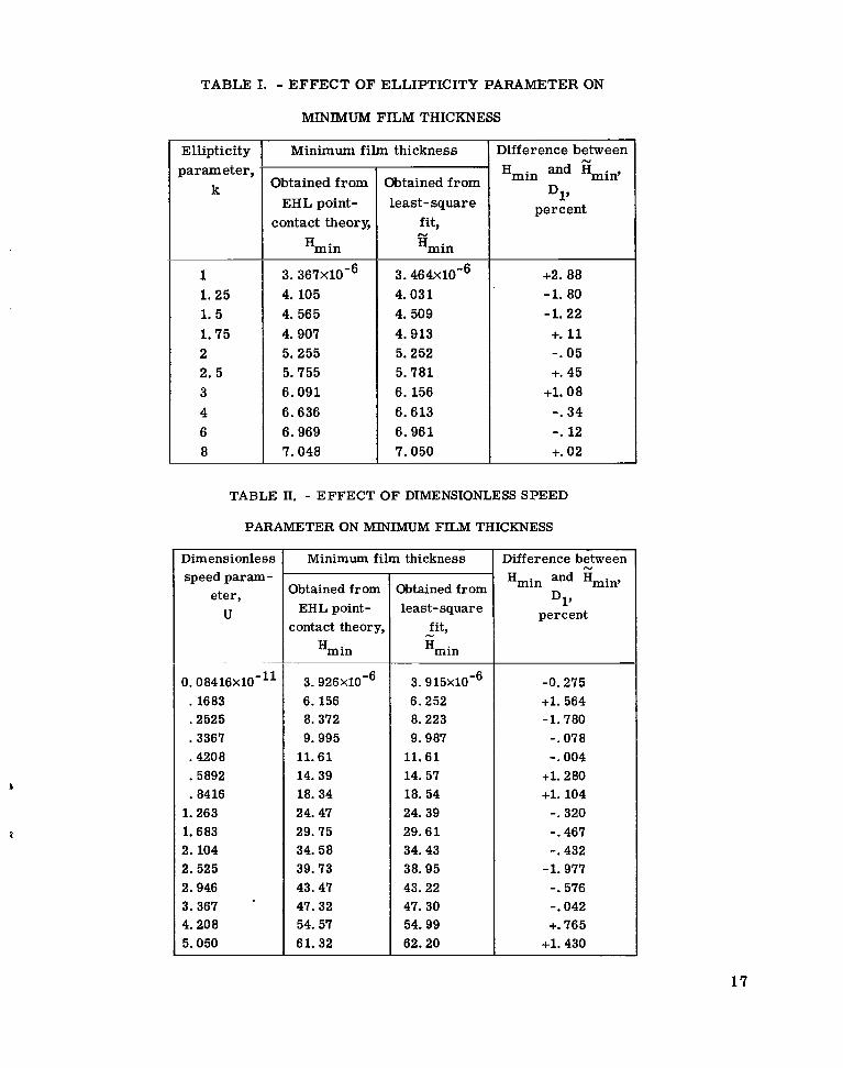
TABLE I. - EFFECT OF ELLIPTICITY PARAMETER ON
Ellipticity parameter ,
k
1 1. 25 1. 5 1.75 2 2.5 3 4 6 8
MINIMUM FILM THICKNESS
Minimum fi lm thickness
Obtained from EHL point-
contact theory,
Hmin
3. 367X10-6 4.105 4. 565 4.907 5.255 5.755 6.091 6.636 6.969 7.048
Obtained from least-square
fit, N
Hmin
3. 464X10-6 4.031 4.509 4.913 5.252 5.781 6.156 6.613 6.961 7.050
Difference between
Hmin and Hmin,
percent
N
D17
+2.88 -1. 80 -1.22 +. 11 -. 05 +. 45
+l. 08 -. 34 -. 12 +. 02
TABLE II. - EFFECT OF DIMENSIONLESS SPEED
PARAMETER ON MINIMUM FILM THICKNESS
Dimensionless speed param-
eter, U
Minimum film thickness I Obtained from
EHL point- contact theor y,
Hm in
Obtained from least-square
fit, N
Hmin
Difference between N
percent
D. 08416X10-11 . 1683 .2525 .3367 .4208 .5892 .a416 1.263 1.683 2. 104 2.525 2.946 3.367 ‘
4.208 5.050
3. 926X1Om6 6.156 8.372 9.995 11.61 14.39 18.34 24.47 29.75 34.58 39.73 43.47 47.32 54.57 61.32
3. 915X10-6 6.252 8.223 9.987 11.61 14.57 18.54 24.39 29.61 34.43 38.95 43.22 47.30 54.99 62.20
-0.275 +l. 564 -1.780 -. 078 -. 004
+l. 280 +l. 104 -. 320 -. 467 -. 432 -1.977 -. 576 -. 042 +. 765
+l. 430
17
terial
Bronze Bronze Steel Silicon
nitride
6. 931X10-6
17 .19
6.311 6.080
TABLE Ill. - EFFECT OF DIMENSIONLESS LOAD PARAMETER
ON MINIMUM FILM THICKNESS
6. 813X10-6
11.404
6.336
6 . 0 3 8
Dimensionless I Minimum film thickness 1 Difference between N
load param- eter,
W
Obtained from EHL point-
contact theory,
Hmin
0. 1106X10-6 . 2 2 1 1 .3686 .5528 . 7 3 7 1 .9214
1.106 1.290
6. 969x1Om6 6.492 6.317 6.268 6.156 6.085 5 .811 5.657
Obtained from least- square
fit, percent
Hmin I 6. 941X10-6 6.599 6.358 6. 172 6.044 5.947 5. 868 5. 803
- 0 . 4 1 +l. 65 +. 64
-1. 52 - 1 . 8 1 -2.27 +. 98
+2. 58
TABLE IV. - EFFECT OF SOLID MATERIAL AND LUBRICANT AS REPRESENTED IN DIMENSIONLESS
MATERIAL PARAMETER ON MINIMUM FILM THICKNESS
Lubricant
Paraffinic Naphthenic Paraffinic Paraffinic
Dimensionless material pa-
rameter, G
2310
3591
4522 6185
Dimensionless speed param-
eter, U
0. 3296X10-11
.9422
. 1683
.1122
.~
Dimensionless load param-
eter, W
0. 1216X10-6
. 7 2 1 6
. 3686
.2456
Difference between Y
Hmin and Hmin’ D1’
percent
- 0 . 8 4
+l. 25
+. 3 1
-. IO
I
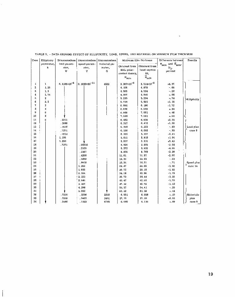
TABLE V. - DATA SHOWlNG EFFECT OF ELLIPTICITY, LOAD, SPEED, AND MATERIAL ON MINIMUM FILM THICKNESS
!
lase
1 2 3 4 5 6 I 8 9
10
11 12 13 14 15 16 17 18 19 20 2 1 22 23 24 25 26 21 28 29 30 3 1 32 33 34
Ellipticity iarameter,
k
1 1. 25 1. 5 1.75 2 2. 5 3 4 6 8
.7 6
,1216 .2456
)imensionless Dimensionless speed param- material pa-
eter, U
I. 1f
. O l
.2525 ,3367 ,4208 .5892 ,8416
[. 263 1.683 !. 104 !. 525 !. 946 $. 361 L. 208 i. 050 ,3296 .9422 ,1122
x10-11
.6
meter, G
4522
2 )
3491 6785
Minimum film thickness
Xtained from EHL point-
:ontact theory,
Hmin
3. 361X10'6 4. 105 4. 565 4.901 5.255 5.155 6.091 6.636 6.969 I. 048
6.492 6. 317 6. 268 6. 156 6.085 5.811 5.657 3.926 8.312 9.995
11.61 14.39 18.34 24.47 29.75 34.58 39.73 43.41 47. 32 54. 51 61.32
11.19 6.931
6.080
lbtained from least-square
fit,
*,in -
3. 514x10-6 4.018 4.554 4.955 5.294 5.821 6. 196 6.652 I. 001 I. 091 6.656 6.412 6.225 6.095 5.991 5.918 5.851 3.805 8.032 9.169
11.31 14.29 18.21 24.00 29.18 33.96 38.44 42.69 46.16 54.41 61.59
6.938
6. 116 11.59
D1. percent
c4.31 -. 66 -. 24 +. 98 +. 1 4
+l. 15 +l. 72 +. 24 +. 46 +. 61
+2.53 +l. 50 -. 69 -. 99
-1.45 +l. 84 +3.43 -3.08 -4.06 -2.26 -2.01 -. 69 -. I1
-1.92 -1.92 -1. I 9 -3.25 -1. I 9 -1.18 -. 29 +. 44 +. 10
+2.33 +. 59
Mference betweer
Hmin and Hminl I
~
Results
Ellipticity
Load plus case 9
Speed plu; case 14
Materials
case 9 plus
19

TABLE VI. - DATA SHOWING EFFECT OF ELLW?WITY, LOAD, SPEED, AND MATERIAL ON CENTRAL FILM THICKNESS
Difference between
HC and Hcs
percent D2’
Dimensionles material pa-
rameter, G
Results
4522
Ellipticity
case 9
I Speed plus * case 14
1 Materials 2310
3591 6785
EHL point- contact theor]
6. 860x10-6 6.964 I. 001 7.015 7. 402 7.653 I. 845 8.292 8.657 8.672 7.796 7.505 1.309 I. 511 7.611 7.416 6.762 4.917 9.999 11.40 13.07 17.13 21.35 29.62 35.50 41.05 46.64 51.08 55.56 63.81 11.25 8.422
1. 825 20.70
I i Obtained frort
least-square fit, - HC
6. 215x10-6 6.647 I. 006 I. 306 I. 556 I. 931 8.202 8. 513 8.736 8.787 8.339 8.059 7.843 7.693 7.578 7.487 7.410 4.836 10.10 12.24 14.21 17.81 22.61 29.68 35.98 41.79 47.22 52.36 57.26 66.49 75.13 8.466 21.62 7.825
-9.40 -4.55 +. 07 +4.15 +2.08 +3. I1 c4.55 +2.67 +. 91 +l. 33 4.97 +I. 38 +I. 31 c2.34 -. 43 +. 96 +9.58 -1.65 +l. 01 +7.31 + & I 2 +3.97 +5.90 +. 20 +l. 35 +l. 80 +l. 24 +2.5I +LO6 +4.20 +5.45
: .52 +4.44 0
20
Dimension less pressure, P = plE'
A 0.70~10-~ B .66 C .60 D .50 E .40 F .30 G .20 H .10
(a) k = 8. Figure 1. Contour plots of dimensionless pressure for ellipticity parameters k of 8
and 1.25, respectively. The dimensionless parameters U, W, and G are held con- stant as defined in equation (7).
21

D h e n sion less pressure, P = PIE'
A 1.7~10-~ B 1.6 c 11.5 D 1.4 E 1.2 F 1.0 G .7 H . 3
(b) k = 1.25.
Figure 1. - Concluded.
22

Dimension less film thickness,
H = hlR,
A 7 . 0 8 d B 7.20
D 7.70 E 8.20 F 8.90 G 9.80 H 11.00
c 7.40
23

B imension less film thickness,
H = hlR,
A 4 . 3 ~ 1 0 - ~ B 4.6 C 5.0 D 5.5 E 6.0 F 6.6 G 7.4 H 8.2
(b) k = 1.25. Figure 2. - Concluded.
24
2.0
1.8
1.6
Ellipticity parameter,
k
-2 .4 -2 .0 -1.6 -1.2 -.a - - .4 0 .4 .8 1.2 X
(a) Dimensionless pressure.
Figure 3. - Variation of dimensionless pressure and film thickness onx-axis for three values of ellipticity parameter. The value of v is held fixed near axial cen- ter of contact.
25
18
16
14
12
10
2 a 1 p
20-
-
-
-
-
-
8 -
6-
(b) Dimensionless f i lm thickness.
Figure 3. - Concluded.
41
26
I I I I 1 I 1 I
Dimension less pressure, P = PIE '
A 1 . 5 ~ 1 0 - ~ B 1.4 c 1.3 D 1.2 E 1.1 F .9 G .6
Figure 4. - Contour plots of dimensionless pressure for dimensionless speed param- eters U of 0 . 8 4 1 6 ~ 1 0 - ~ ~ and 0. 505(bt10-10, respectively. The dimensionless param- eters k, W, and G are held constant as defined in equation 03).
27
Dimensionless pressure, P = plE'
A 1 .8~10-~ B 1.6 C 1.4 D 1.3 E 1.1 F .9 G .6 H . 3
(b) U = 0.505(1x10⁻¹⁰. Figure 4. - Concluded.
28
Dimensionless film thickness,
H = hlR,
A 4 . 2 5 ~ 1 0 ~ ~ B 4.60 C 5.00 D 5.50 E 6.00 F 7.00 G 8.00 H 10.00
(a) u - o.~w&x~o-~* . Figure 5. - Contour plots of dimensionless film thickness for dimensionless speed pa-
rameters U of 0 . 8 4 1 6 ~ 1 6 ~ ~ and 0.50W10-10. The dimensionless parameters k, w, and G are held constant as defined in equation (13).
29
Dimensionless fi lm thickness,
H = hlR,
A 61 .4~10-~ B 62.0 C 63.0 D 65.0 E 68.0 F 72.0 G 78.0 H 86.0
H
t
x
x
*
*
. - - . . .
(b) U = 0.5050x10⁻¹⁰. Figure 5. - Concluded.
30
2.2
2.0
1.8
1.6
- W - ? 1.4 a a- L
2 1.2 v) W L P v) v)
2 1.0 I= 0 v) IT .-
.E .8 a
.6
. 4
.2
Dimensionless speed parameter,
U
0.5050x10⁻¹⁰ A
I -!.4 -2.0 -1.6 -1.2 -.8 - -.4 .4 .8 1.2
X
(a) Dimensionless f i lm thickness.
Figure 6. - Variation of dimensionless pressure and f i lm thickness o n x-axis for three values of dimensionless speed parameter. The value of 7 is held fixed near axial center of contact.
31
110x1 0-6
100-
90 -
- ex 80- c
I I1
vi 70- VI aJ t: Y V .- 5 60- E - .- Y-
VI VI
c 0 VI tI Q,
22 50- .-
.E 40- n
30-
20 -
10 -
I I - - I I J 0 . 4 .8 1.2
0 -2.4 -2.0 -1.6 -1.2 -.8 - .4 -
X
( b ) Dimensionless f i lm thickness.
Figure 6. - Concluded.
32
D i mens ion I es s pressure, P = pCE'
A 0 . 8 3 ~ 1 0 - ~ B .75 C .65 D .55 E .45 F -35 G .25 H .15
(a) W - 0.1106~10-~. Figure 7. - Contou plots of dimens'onless pressure for dimensionless load parameters
W of 0.1106xlO- 6 and 0 . 1 2 9 0 x l d , respectively. The dimensionless parameters k, U, and G are held constant as defined in equation (18).
33

D i men si0 n less pressure, P = PIE'
A 1 . 8 ~ 1 0 - ~ B 1.7 C 1.6 D 1.4
E 1.1 F .7 G .2
( b ) W = 0.1290~10-~. Figure 7. - Concluded.
34

Dimensionless fi lm thickness,
H = hlR,
A 7 . 0 ~ 1 6 ~ B 7.2 c 7.4 D 7.7 E 8.1 F 8.7 G 9.5 H 10.7
(a) w = 0.1106~10-~. Figure 8. - Contour plots of d i ensionless f i lm thickness for dimensionless load
parameters W of 0.1106~10 -'6 and 0. ~ Z ~ O X ~ O - ~ , respectively. The dimensionless parameters k, W, and G are held constant as defined in equation (18).
35
D i men sion less f i lm thickness,
H = hlR,
A 6 . 1 ~ 1 0 - ~ B 6.5 C 7.0 D 7.7 E 8.7 F 10.0
( b ) W = 0.1290~10-~. Figure 8. - Concluded.
36
Dimension less load,
W
- 2 . 4 -2 .0 - l , 6 -1.2 - * 8 - -,4 0 . 4 .s 1 .2 Y
(a) Dimensionless pressure.
F@L;re 9, - Variation of dinensionless pressure and f i lm thickness on X-axis for three values of dinensionless load parameter. The value of v i s held fixed near zqial center of contact.
37

38
24x
22
20
18
16
14
14
1(
1
Dimensionless load, W
2 1 .2.4 -2.0 -1.6 - 0 .4 -1.2 -.8 -.4 .8
X
(b) Dimensionless f i l m thickness. Figure 9. - Concluded.


![[Hamrock] elementos de máquinas](https://img.dokumen.tips/doc/110x75/5a664d467f8b9a44398b482d/hamrock-elementos-de-maquinas.jpg)