Embed Size (px)
DESCRIPTION
prestressed concrete stuctures
Citation preview

© BIS 2003
B U R E A U O F I N D I A N S T A N D A R D SMANAK BHAVAN, 9 BAHADUR SHAH ZAFAR MARG
NEW DELHI 110002
IS : 1343 - 1980(Reaffirmed 1999)
Edition 2.1(1984-10)
Price Group 11
Indian StandardCODE OF PRACTICE FOR
PRESTRESSED CONCRETE
( First Revision )(Incorporating Amendment No. 1)
UDC 624.012.46 : 006.76

IS : 1343 - 1980
© BIS 2003
BUREAU OF INDIAN STANDARDS
This publication is protected under the Indian Copyright Act (XIV of 1957) andreproduction in whole or in part by any means except with written permission of thepublisher shall be deemed to be an infringement of copyright under the said Act.
Indian StandardCODE OF PRACTICE FOR
PRESTRESSED CONCRETE
( First Revision )Cement and Concrete Sectional Committee, BDC 2
Chairman Representing
DR H. C. VISVESVARAYA Cement Research Institute of India, New Delhi
Members
ADDITIONAL DIRECTOR, STANDARDS (B & S)
Research, Designs & Standards Organization(Ministry of Railways), Lucknow
DEPUTY DIRECTOR, STANDARDS (B & S) ( Alternate )
SHRI K. P. BANERJEE Larsen & Toubro Ltd, BombaySHRI HARISH N. MALANI ( Alternate )
SHRI S. K. BANERJEE National Test House, CalcuttaSHRI R. N. BANSAL Beas Designs Organization, Nangal Township
SHRI T. C. GARG ( Alternate )CHIEF ENGINEER (DESIGNS) Central Public Works Department, New Delhi
EXECUTIVE ENGINEER (DESIGNS) III( Alternate )
CHIEF ENGINEER (PROJECTS) Irrigation Department, Government of Punjab,Chandigarh
DIRECTOR, IPRI ( Alternate )DIRECTOR (CSMRS) Central Water Commission, New Delhi
DEPUTY DIRECTOR (CSMRS) ( Alternate )DR R. K. GHOSH Central Road Research Institute (CSIR), New Delhi
SHRI Y. R. PHULL ( Alternate I )SHRI M. DINAKARAN ( Alternate II )
DR R. K. GHOSH Indian Roads Congress, New DelhiSHRI B. R. GOVIND Engineer-in-Chief’s Branch, Army Headquarters,
New DelhiSHRI P. C. JAIN ( Alternate )
SHRI A. K. GUPTA Hyderabad Asbestos Cement Products Ltd,Hyderabad
DR R. R. HATTIANGADI The Associated Cement Companies Ltd, BombaySHRI P. J. JAGUS ( Alternate )
DR IQBAL ALI Engineering Research Laboratories, HyderabadSHRI S. R. KULKARNI M. N. Dastur & Co Pvt Ltd, Calcutta
( Continued on page 2 )

IS : 1343 - 1980
2
( Continued from page 1 )
Members RepresentingSHRI S. K. LAHA The Institution of Engineers (India), Calcutta
SHRI B. T. UNWALLA ( Alternate )DR MOHAN RAI Central Building Research Institute (CSIR), Roorkee
DR S. S. REHSI ( Alternate )SHRI K. K. NAMBIAR In personal capacity ( ‘Ramanalaya’ 11 First Crescent
Park Road, Gandhi Nagar, Adyar, Madras )SHRI H. S. PASRICHA Hindustan Prefab Ltd, New Delhi
SHRI C. S. MISHRA ( Alternate )DR M. RAMAIAH Structural Engineering Research Centre (CSIR),
RoorkeeDR N. S. BHAL ( Alternate )
SHRI G. RAMDAS Directorate General of Supplies and Disposals, NewDelhi
DR A. V. R. RAO National Buildings Organization, New DelhiSHRI J. SEN GUPTA ( Alternate )
SHRI R. V. CHALAPATHI RAO Geological Survey of India, CalcuttaSHRI S. ROY ( Alternate )
SHRI T. N. S. RAO Gammon India Ltd, BombaySHRI S. R. PINHEIRO ( Alternate )
SHRI ARJUN RIJHSINGHANI Cement Corporation of India Ltd, New DelhiSHRI K. VITHAL RAO ( Alternate )
SECRETARY Central Board of Irrigation and Power, New DelhiDEPUTY SECRETARY (I) ( Alternate )
SHRI N. SIVAGURU Roads Wing, Ministry of Shipping and Transport,New Delhi
SHRI R. L. KAPOOR ( Alternate )SHRI K. A. SUBRAMANIAM The India Cements Ltd, Madras
SHRI P. S. RAMACHANDRAN ( Alternate )SUPERINTENDING ENGINEER
(DESIGNS)Public Works Department, Government of Tamil
Nadu, MadrasEXECUTIVE ENGINEER (SM & R
DIVISION) ( Alternate )SHRI L. SWAROOP Dalmia Cement (Bharat) Ltd, New Delhi
SHRI A. V. RAMANA ( Alternate )SHRI B. T. UNWALLA The Concrete Association of India, Bombay
SHRI Y. K. MEHTA ( Alternate )SHRI D. AJITHA SIMHA,
Deputy Director General [Former Director (Civ Engg)] Director General, ISI ( Ex-officio Member )
SHRI G. RAMAN,Director (Civ Engg)
Former SecretarySHRI D. AJITHA SIMHA
Deputy Director General[Former Director (Civ Engg)], ISI
SecretarySHRI M. N. NEELAKANDHAN
Assistant Director (Civ Engg), ISI( Continued on page 61 )

IS : 1343 - 1980
3
CONTENTS
PAGE
0. FOREWORD 6
SECTION 1 GENERAL
1. SCOPE 8
2. TERMINOLOGY 9
3. SYMBOLS 10
SECTION 2 MATERIALS, WORKMANSHIP, INSPECTION AND TESTING
4. MATERIALS 12
4.1 CEMENT 12
4.2 AGGREGATES 12
4.3 WATER 13
4.4 ADMIXTURES 13
4.5 PRESTRESSING STEEL 13
4.6 UNTENSIONED STEEL 14
4.7 STORAGE OF MATERIALS 14
5. CONCRETE 15
5.1 GRADES 15
5.2 PROPERTIES OF CONCRETE 15
6. WORKABILITY OF CONCRETE 17
7. DURABILITY 17
8. CONCRETE MIX PROPORTIONING 18
8.1 MIX PROPORTION 18
8.2 DESIGN MIX CONCRETE 19
9. PRODUCTION AND CONTROL OF CONCRETE 19
9.1 QUALITY OF MATERIALS 19
10. FORMWORK 19
11. ASSEMBLY OF PRESTRESSING AND REINFORCING STEEL 19
11.1 PRESTRESSING STEEL 19

IS : 1343 - 1980
4
PAGE
11.2 SHEATHS AND EXTRACTABLE CORES 22
11.3 REINFORCING STEEL 23
12. PRESTRESSING 23
12.1 PRESTRESSING EQUIPMENT 23
12.2 PROCEDURE FOR TENSIONING AND TRANSFER 25
12.3 GROUTING 26
13. TRANSPORTING, PLACING, COMPACTING AND CURING 28
14. CONCRETING UNDER SPECIAL CONDITIONS 29
14.1 WORK IN EXTREME WEATHER CONDITIONS 29
15. SAMPLING AND STRENGTH TEST OF CONCRETE 29
16. ACCEPTANCE CRITERIA 30
17. INSPECTION AND TESTING OF STRUCTURES 30
SECTION 3 GENERAL DESIGN REQUIREMENTS
18. GENERAL DESIGN REQUIREMENTS 30
SECTION 4 STRUCTURAL DESIGN: LIMITSTATE METHOD
19. SAFETY AND SERVICEABILITY REQUIREMENTS 38
19.1 LIMIT STATE DESIGN 38
19.2 LIMIT STATE OF COLLAPSE 38
19.3 LIMIT STATES OF SERVICEABILITY 39
20. CHARACTERISTIC AND DESIGN VALUES AND PARTIAL SAFETY FACTORS 40
20.1 CHARACTERISTIC STRENGTH OF MATERIALS 40
20.2 CHARACTERISTIC LOADS 40
20.3 DESIGN VALUES 40
20.4 PARTIAL SAFETY FACTORS 41
21. ANALYSIS 41
21.1 ANALYSIS OF STRUCTURE 41

IS : 1343 - 1980
5
PAGE
22. LIMIT STATE OF COLLAPSE 43
22.1 LIMIT STATE OF COLLAPSE: FLEXURE 43
22.2 LIMIT STATE OF COLLAPSE: COMPRESSION 46
22.3 LIMIT STATE OF COLLAPSE: TENSION 46
22.4 LIMIT STATE OF COLLAPSE: SHEAR 46
22.5 LIMIT STATE OF COLLAPSE: TORSION 49
22.6 LIMIT STATE OF SERVICEABILITY: DEFLECTION 52
22.7 LIMIT STATE OF SERVICEABILITY: CRACKING 53
22.8 LIMIT STATE OF SERVICEABILITY: MAXIMUM COMPRESSION 54
APPENDIX A REQUIREMENTS FOR DURABILITY 57
APPENDIX B MOMENTS OF RESISTANCE FOR RECTANGULAR AND T-SECTIONS 59

IS : 1343 - 1980
6
Indian StandardCODE OF PRACTICE FOR
PRESTRESSED CONCRETE
( First revision )0. F O R E W O R D
0.1 This Indian Standard (First Revision) was adopted by the IndianStandards Institution on 30 December 1980, after the draft finalizedby the Cement and Concrete Sectional Committee had been approvedby the Civil Engineering Division Council.
0.2 This standard was first published in 1960. This revision was takenup with a view to keeping abreast with the rapid development in thefield of concrete technology and also to bring in further clarificationsand modifications in the light of experience gained while applying theprovisions of the earlier version of the code to practical situations.
0.3 The format and arrangement of clauses in the code have beenchanged from the earlier version. The matter has now been dividedinto four sections as follows:
Section 1 GeneralSection 2 Materials, Workmanship, Inspection and TestingSection 3 General Design RequirementsSection 4 Structural Design: Limit State Method
0.3.1 In this revision, an attempt has been made to unify the codalprovisions between prestressed concrete structures and reinforcedconcrete structures, as is necessary. As a result, many of the provisionsin Section 2 Materials, Workmanship, Inspection and Testing andSection 3 General Design Requirements of IS : 456-1978* apply toprestressed concrete structures and, therefore, only reference has beenmade to such provisions in this code.
0.3.2 In some clauses, the code recommends reference to specialistliterature, since the current knowledge on some aspects of design hasnot yet crystallized. This has also been done in order to avoidburdening the code with a lot of details which may not be required forthe design of great majority of structures.
*Code of practice for plain and reinforced concrete ( third revision ).

IS : 1343 - 1980
7
0.3.3 SI Units have been used in this code, the values of stresses beingin units of N/mm2. While converting the values from the earlier unitsof kg/cm2, the values have been rationalized rather than giving theexact conversion.0.3.4 While deciding on the symbols used in this code, therecommendations of ISO 3898-1976* have been taken intoconsideration. However, considering the convenience of the users ofthe code, the familiar symbols of the old version have been retained tothe extent possible.0.4 This revision incorporates a number of important changes. Themajor changes in this revision are on the following lines:
a) The concept of limit state which provides a rational approach,taking into account variations in material strengths and loads onsemi-probabilistic basis, has been introduced. This, in fact, is arationalization of the ultimate load method, covered in the earlierversion.
b) Provision for intermediate degrees of prestress (partial prestress)has been included. Consequently, the code covers 3 types ofstructures, the types being associated with the permissibletensile stress in concrete.
c) The method of design for shear and torsion has been completelyrevised, incorporating the results of the latest research on thesubject.
d) Recommendations regarding transmission length of prestressingtendons have been elaborated.
e) Recommendations for ensuring lateral stability during handlingand erection have been modified.
f) Considerations regarding durability have been detailed withguidance concerning minimum cement content and maximumwater-cement ratio for different environmental conditions,including types of cement to be used for resisting sulphate attack.Limitations on total chloride and sulphate content of concretehave also been given.
0.4.1 In IS : 456-1978†, major changes have been incorporated inprovisions relating to materials, workmanship, inspection and testing,and general design requirements. In view of the attempt at unificationbetween the provisions of reinforced concrete and prestressed concretecodes, these changes are relevant to prestressed concrete code alsowherever reference has been made to related provisions ofIS : 456-1978†.
*Bases for design of structures — Notations — General symbols.†Code of practice for plain and reinforced concrete ( third revision ).

IS : 1343 - 1980
8
0.5 In this code, it has been assumed that the design of prestressedconcrete structures is entrusted to a qualified engineer, and that theexecution of the work is carried out under the direction of anexperienced supervisor.0.6 The Sectional Committee, responsible for the preparation of thisstandard, has taken into consideration the views of manufacturers,users, engineers, architects, builders and technologists and has relatedthe standard to the manufacturing and trade practices followed in thiscountry in this field. Due weightage has also been given to the need forinternational co-ordination among standards prevailing in differentcountries of the world. These considerations led the SectionalCommittee to derive assistance from the following:
ACI 318-77 ACI Standard building code requirements for reinforcedconcrete. American Concrete Institute.
CP 110 : Part I : 1972 Code of practice for the structural use ofconcrete: Part I Design, materials and workmanship. BritishStandards Institution.
AS 1481-1974 SAA Prestressed concrete code. Standards Associationof Australia.
Assistance has also been derived from the published documents of thefollowing organizations:
Comite Euro — International Du BetonInternational Standards Organization
0.7 This edition 2.1 incorporates Amendment No. 1 (October 1984).Side bar indicates modification of the text as the result ofincorporation of the amendment.0.8 For the purpose of deciding whether a particular requirement ofthis standard is complied with, the final value, observed or calculated,expressing the result of a test or analysis, shall be rounded off inaccordance with IS : 2-1960*. The number of significant placesretained in the rounded off value should be the same as that of thespecified value in this standard.
SECTION 1 GENERAL
1. SCOPE1.1 This code deals with the general structural use of prestressedconcrete. It covers both work carried out on site and the manufactureof precast prestressed concrete units.1.2 Special requirements of structures such as pipes and poles coveredin respective codes have not been covered in this code; these codesshall be used in conjunction with this code.
*Rules for rounding off numerical values ( revised ).

IS : 1343 - 1980
9
2. TERMINOLOGY
2.0 For the purpose of this code, the definitions given inIS : 4845-1968* and IS : 6461 (Parts I to XII)† shall generally apply;however, some of the important definitions are given below:
2.1 Anchorage — In post-tensioning, a device used to anchor thetendon to the concrete member; in pre-tensioning, a device used toanchor the tendon during hardening of the concrete.
2.2 Bonded Member — A prestressed concrete in which tendons arebonded to the concrete either directly or through grouting.
2.3 Bonded Post-tensioning — Post-tensioned construction in whichthe annular spaces around the tendons are grouted after stressing,thereby bonding the tendon to the concrete section.
2.4 Characteristic Load — Load which has 95 percent probability ofnot being exceeded during the life of the structure ( see 20.2 ).
2.5 Characteristic Strength — Strength of material below whichnot more than 5 percent of the test results are expected to fall( see 20.1 ).
2.6 Column or Strut — A compression member of rectangularsection, the effective length of which exceeds three times the leastlateral dimension.
2.7 Creep in Concrete — Increase with time in the strain of concretesubjected to sustained stress.
2.8 Creep Coefficient — The ratio of creep strain to elastic strain inconcrete.
2.9 Final Prestress — The stress which exists after substantially alllosses have occurred.
*Definitions and terminology relating to hydraulic cement.†Glossary of terms relating to cement concrete:
(Part I)-1972 Concrete aggregates(Part II)-1972 Materials (other than cement and aggregate)(Part III)-1972 Reinforcement(Part IV)-1972 Types of concrete(Part V)-1972 Formwork for concrete(Part VI)-1972 Equipment, tools and plant(Part VII)-I973 Mixing, laying, compaction, curing and other construction aspects(Part VIII)-1973 Properties of concrete(Part IX)-1973 Structural aspects(Part X)-1973 Tests and testing apparatus(Part XI)-1973 Prestressed concrete(Part XII)-1973 Miscellaneous

IS : 1343 - 1980
10
2.10 Final Tension — The tension in the steel corresponding to thestate of the final prestress.
2.11 Initial Prestress — The prestress in the concrete at transfer.
2.12 Initial Tension — The maximum stress induced in theprestressing tendon at the time of the stressing operation.
2.13 Post-tensioning — A method of prestressing concrete in whichprestressing steel is tensioned against the hardened concrete.
2.14 Prestressed Concrete — Concrete in which permanent internalstresses are deliberately introduced, usually by tensioned steel, tocounteract to the desired degree the stresses caused in the member inservice.
2.15 Pre-tensioning — A method of prestressing concrete in whichthe tendons are tensioned before concreting.
2.16 Short Column — A column of rectangular section, the effectivelength of which does not exceed 12 times the least lateral dimension.
2.17 Slender Column — A column of rectangular section, theeffective length of which exceeds 12 times the least lateral dimension.
2.18 Shrinkage Loss — The loss of stress in the prestressing steelresulting from the shrinkage of the concrete.
2.19 Stress at Transfer — The stress in both the prestressing tendonand the concrete at the stage when the prestressing tendon is releasedfrom the prestressing mechanism.
2.20 Tendon — A steel element, such as a wire, cable, bar, rod or strandused to impart prestress to concrete when the element is tensioned.
2.21 Transfer — The act of transferring the stress in prestressingtendons from the jacks or pre-tensioning bed to the concrete member.
2.22 Transmission Length — The distance required at the end of apretensioned tendon for developing the maximum tendon stress by bond.
3. SYMBOLS
3.1 For the purpose of this code, the following letter symbols shall havethe meaning indicated against each; where other symbols are used,they are explained at the appropriate place:
A AreaB Breadth of beambw Breadth of web or ribD Overall depth of beam

IS : 1343 - 1980
11
DL Dead loadd Effective depth of beamdt Effective depth of beam in shearEc Modulus of elasticity of concreteEL Earthquake loadEs Modulus of elasticity of steele EccentricityF Characteristic loadFbst Bursting tensile forceFd Design loadf Characteristic strength of materialfci Cube strength of concrete at transferfck Characteristic compressive strength of concretefcp Compressive stress at centroidal axis due to prestress or
average intensity of effective prestress in concretefcr Modulus of rupture of concrete (flexural tensile strength)fd Design strengthfp Characteristic strength of prestressing steelfpe Maximum prestress after lossesfpi Maximum initial prestressfhu Ultimate tensile stress in the tendonsft Maximum principal tensile stressfv Characteristic strength of reinforcementLL Live load or imposed loadM Bending momentm Modular ratios Spacing of stirrupsT Torsional momentV Shear forceVc Ultimate shear resistance of concreteVco Ultimate shear resistance of a section uncracked in flexureVcr Ultimate shear resistance of a section cracked in flexureWL Wind loadxu Depth of neutral axis
Partial safety factor for load
Partial safety factor for materialf
m

IS : 1343 - 1980
12
SECTION 2 MATERIALS, WORKMANSHIP,INSPECTION AND TESTING
4. MATERIALS
4.1 Cement — The cement used shall be any of the following, with theprior approval of the engineer-in-charge:
a) Ordinary Portland cement conforming to IS : 269-1976*;b) Portland slag cement conforming to IS : 455-1976†, but with not
more than 50 percent slag content;c) Rapid-hardening Portland cement conforming to IS : 8041-1978‡;
andd) High strength ordinary Portland cement conforming to
IS : 8112-1976§.
4.2 Aggregates — All aggregates shall comply with the requirementsof IS : 383-1970||.
4.2.1 The nominal maximum size of coarse aggregate shall be as largeas possible subject to the following:
a) In no case greater than one-fourth the minimum thickness of themember, provided that the concrete can be placed withoutdifficulty so as to surround all prestressing tendons andreinforcements and fill the corners of the form.
b) It shall be 5 mm less than the spacing between the cables,strands or sheathings where provided.
c) Not more than 40 mm; aggregates having a maximum nominalsize of 20 mm or smaller are generally considered satisfactory.
4.2.2 Coarse and fine aggregates shall be batched separately.
δm Percentage reduction in momentτc Shear stress in concreteφ Diameter of tendon or bar
*Specification for ordinary and low heat Portland cement ( third revision ).†Specification for Portland slag cement ( third revision ).‡Specification for rapid hardening Portland cement ( first revision ).§Specification for high strength ordinary Portland cement.||Specification for coarse and fine aggregates from natural sources for concrete
( second revision ).
IS : 1343 - 1980
13
4.3 Water — The requirements of water used for mixing and curingshall conform to the requirements given in IS : 456-1978*. However,use of sea water is prohibited.
4.4 Admixtures — Admixtures may be used with the approval of theengineer-in-charge. However use of any admixture containingchlorides in any form is prohibited.
4.4.1 The admixtures shall conform to IS : 9103-1979†.
4.5 Prestressing Steel
4.5.1 The prestressing steel shall be any one of the following:a) Plain hard-drawn steel wire conforming to IS : 1785 (Part I)-
1966‡ and IS : 1785 (Part II)-1967§,b) Cold-drawn indented wire conforming to IS : 6003-1970||, c) High tensile steel bar conforming to IS : 2090-1962¶, andd) Uncoated stress relieved strand conforming to IS : 6006-1970**.
4.5.1.1 All prestressing steel shall be free from splits, harmfulscratches, surface flaws; rough, jagged and imperfect edges and otherdefects likely to impair its use in prestressed concrete. Slight rust maybe permitted provided there is no surface pitting visible to the nakedeye.
4.5.2 Coupling units and other similar fixtures used in conjunctionwith the wires or bars shall have an ultimate tensile strength of notless than the individual strengths of the wires or bars being joined.
4.5.3 Modulus of Elasticity — The value of the modulus of elasticity ofsteel used for the design of prestressed concrete members shallpreferably be determined by tests on samples of steel to be used for theconstruction. For the purposes of this clause, a value given by themanufacturer of the prestressing steel shall be considered as fulfillingthe necessary requirements.
*Code of practice for plain and reinforced concrete ( third revision ).†Specification for admixtures for concrete.‡Specification for plain hard-drawn steel wire for prestressed concrete: Part I
Cold-drawn stress-relieved wire ( revised ).§Specification for plain hard-drawn steel wire for prestressed concrete: Part II
As-drawn wire.||Specification for indented wire for prestressed concrete.¶Specification for high tensile steel bars used in prestressed concrete.**Specification for uncoated stress relieved strand for prestressed concrete.

IS : 1343 - 1980
14
4.5.3.1 Where it is not possible to ascertain the modulus of elasticityby test or from the manufacturer of the steel, the following values maybe adopted:
4.6 Untensioned Steel — Reinforcement used as untensioned steelshall be any of the following:
a) Mild steel and medium tensile steel bars conforming to IS : 432(Part I)-1966¶,
b) Hot-rolled deformed bars conforming to IS : 1139-1966**,
c) Cold-twisted bars conforming to IS : 1786-1979††, and
d) Hard-drawn steel wire fabric conforming to IS : 1566-1967‡‡.
4.7 Storage of Materials — Storage of materials shall be as perIS : 4082-1978§§.
Type of Steel Modulus of Elasticity,E, kN/mm2
Plain cold-drawn wires [conforming toIS : 1785 (Part I)-1966*, IS : 1785(Part II)-1967† and IS : 6003-1970‡]
210
High tensile steel bars rolled orheat-treated (conforming to IS : 2090-1962§)
200
Strands (conforming to IS : 6006-1970||) 195
*Specification for plain hard-drawn steel wire for prestressed concrete: Part I Colddrawn stress-relieved wire ( revised ).
†Specification for plain hard drawn steel wire for prestressed concrete: Part II As-drawn wire.
‡Specification for indented wire for prestressed concrete.§Specification for high tensile steel bars used in prestressed concrete.||Specification for uncoated stress relieved strand for prestressed concrete.¶Specification for mild steel and medium tensile steel bars and hard drawn steel wire
for concrete reinforcement: Part I Mild steel and medium tensile steel bars ( secondrevision ).
**Specification for hot rolled mild steel, medium tensile steel and high yield strengthsteel deformed bars for concrete reinforcement ( revised ).
††Specification for cold-worked steel high strength deformed bars for concretereinforcement ( second revision ).
‡‡Specification for hard-drawn steel wire fabric for concrete reinforcement ( firstrevision ).
§§Recommendations on stacking and storage of construction materials at site.

IS : 1343 - 1980
15
5. CONCRETE
5.1 Grades — The concrete shall be in grades designated as per Table 1.
5.1.1 The characteristic strength of concrete is defined as the strengthof the concrete below which not more than 5 percent of the test resultsare expected to fall.
5.2 Properties of Concrete
5.2.1 Increase in Strength with Age — Where it can be shown that amember will not receive its full design stress within a period of 28 daysafter the casting of the member (for example, in foundations and lowercolumns in multi-storey buildings); the characteristic compressivestrength given in Table 1 may be increased by multiplying by thefactors given below:
TABLE 1 GRADES OF CONCRETE( Clauses 5.1, 5.2.1, 8.2.1 and 20.1 )
GRADE DESIGNATION SPECIFIED CHARACTERISTICCOMPRESSIVE STRENGTH
AT 28 DAYSN/mm2
(1) (2)M 30M 35M 40M 45M 50M 55M 60
30354045505560
NOTE 1 — In the designation of a concrete mix, letter M refers to the mix and thenumber to the specified characteristic compressive strength of 15-cm cube at 28 days,expressed in N/mm2.
NOTE 2 — For pre-tensioned prestressed concrete, the grade of concrete shall be notless than M 40.
Minimum Age of Member When Full Design Stress is Expected
(Months)
Age Factor
136
12
1.01.101.151.20
NOTE 1 — Where members are subjected to lower direct load during construction,they should be checked for stresses resulting from combination of direct load andbending during construction.
NOTE 2 — The design strength shall be based on the increased value of compressivestrength.

IS : 1343 - 1980
16
5.2.2 Tensile Strength of Concrete — The flexural strength shall beobtained as per IS : 516-1959*. When the designer wishes to use anestimate of the flexural strength from the compressive strength, thefollowing formula may be used:
fcr = 0.7 N/mm2
wherefcr = flexural strength in N/mm2, andfck = characteristic compressive strength of concrete in N/mm2.
5.2.3 Elastic Deformation — The modulus of elasticity is primarilyinfluenced by the elastic properties of the aggregate and to a lesserextent by the conditions of curing and age of the concrete, the mixproportions and the type of cement. The modulus of elasticity isnormally related to the compressive strength of concrete.
5.2.3.1 In the absence of test data, the modulus of elasticity forstructural concrete may be assumed as follows:
Ec = 5 700
whereEc = short-term static modulus of elasticity in N/mm2, andfck = characteristic compressive strength of concrete in N/mm2.
5.2.4 Shrinkage — The shrinkage of concrete depends upon theconstituents of concrete, size of the member and environmentalconditions. For a given environment, the shrinkage of concrete is mostinfluenced by the total amount of water present in the concrete at thetime of mixing and, to a lesser extent, by the cement content.
5.2.4.1 In the absence of test data, the approximate value of shrinkagestrain for design shall be assumed as follows:
For pre-tensioning = 0.000 3
For post-tensioning =
wheret = age of concrete at transfer in days.NOTE — The value of shrinkage strain for design of post-tensioned concrete may beincreased by 50 percent in dry atmospheric conditions, subject to a maximum valueof 0.000 3.
5.2.4.2 For the calculation of deformation of concrete at some stagebefore the maximum shrinkage is reached, it may be assumed that
*Methods of test for strength of concrete.
fck
fck
0.000 2Log10 t 2+( )-----------------------------------

IS : 1343 - 1980
17
half of the shrinkage takes place during the first month and that aboutthree-quarters of the shrinkage takes place in first six months aftercommencement of drying.
5.2.5 Creep of Concrete — Creep of concrete depends, in addition to thefactors listed in 5.2.4 on the stress in the concrete, age at loading andthe duration of loading. As long as the stress in concrete does notexceed one-third of characteristic compressive strength, creep may beassumed to be proportional to the stress.
5.2.5.1 In the absence of experimental data and detailed informationon the effect of the variables, the ultimate creep strain may beestimated from the following values of creep coefficient (that is,ultimate creep strain/elastic strain at the age of loading):
NOTE — The ultimate creep strain estimated as per 5.2.5.1 does not include theelastic strain.
5.2.5.2 For the calculation of deformation at some stage before thetotal creep is reached, it may be assumed that about half the totalcreep takes place in the first month after loading and that aboutthree-quarters of the total creep takes place in the first six monthsafter loading.
5.2.6 Thermal Expansion — The coefficient of thermal expansiondepends on nature of cement, the aggregate, the cement content, therelative humidity and the size of sections. For values of coefficient ofthermal expansion for concrete with different aggregates, clause 5.2.6of IS : 456-1978* may be referred to.
6. WORKABILITY OF CONCRETE
6.1 The concrete mix proportions chosen should be such that theconcrete is of adequate workability for the placing conditions of theconcrete and can properly be compacted with the means available.Suggested ranges of values of workability of concrete are given inIS : 456-1978*.
7. DURABILITY
7.1 The durability of concrete depends on its resistance todeterioration and the environment in which it is placed. The resistance
Age at Loading Creep Coefficient7 days 2.2
28 days 1.61 year 1.1
*Code of practice for plain and reinforced concrete ( third revision ).

IS : 1343 - 1980
18
of concrete to weathering, chemical attack, abrasion, frost and firedepends largely upon its quality and constituent materials. Thestrength alone is not a reliable guide to the quality and durability ofconcrete; it must also have an adequate cement content and a lowwater-cement ratio.
7.1.1 One of the main characteristics influencing the durability ofconcrete is its permeability. With strong, dense aggregates, a suitablylow permeability is achieved by having a sufficiently low water-cementratio, by ensuring as thorough compaction of the concrete as possibleand by ensuring sufficient hydration of cement through proper curingmethods. Therefore, for given aggregates, the cement content shouldbe sufficient to provide adequate workability with a low water-cementratio so that concrete can be thoroughly compacted with the meansavailable.
7.2 Appendix A provides guidance regarding minimum cement contentand permissible limits of chloride and sulphate in concrete.
8. CONCRETE MIX PROPORTIONING
8.1 Mix Proportion — The mix proportions shall be selected toensure that the workability of the fresh concrete is suitable for theconditions of handling and placing, so that after compaction itsurrounds all prestressing tendons and reinforcements if present andcompletely fills the formwork. When concrete is hardened, it shall havethe required strength, durability and surface finish.
8.1.1 The determination of the proportions of cement, aggregates andwater to attain the required strengths shall be made by designing theconcrete mix. Such concrete shall be called ‘Design mix concrete’.
For prestressed concrete construction, only ‘Design mix concrete’ shallbe used. The cement content in the mix should preferably not exceed530 kg/m3.
8.1.2 Information Required — In specifying a particular grade ofconcrete, the information to be included shall be:
a) Grade designation,b) Type of cement,c) Maximum nominal size of aggregates,d) Minimum cement content,e) Maximum water-cement ratio, andf) Workability.

IS : 1343 - 1980
19
8.1.2.1 In appropriate circumstances, the following additionalinformation may be specified:
a) Type of aggregate,b) Maximum cement content, andc) Whether an admixture shall or shall not be used and the type of
admixture and the conditions of use.8.2 Design Mix Concrete8.2.1 The mix shall be designed to produce the grade of concretehaving the required workability and a characteristic strength not lessthan appropriate values given in Table 1. The procedure given inIndian Standard Recommended guidelines for concrete mix design( under preparation ) may be followed.
9. PRODUCTION AND CONTROL OF CONCRETE9.1 Quality of Materials — It is essential for designers andconstruction engineers to appreciate that the most effective use ofprestressed concrete is obtained only when the concrete and theprestressing steel employed are of high quality and strength.9.2 The provisions of 9 of IS : 456-1978* shall apply; except that nohandmixing shall be permitted in prestressed concrete work.
10. FORMWORK10.1 The provisions of 10 of IS : 456-1978* shall generally apply. Inaddition, 10.1.1 shall also apply.10.1.1 Moulds for pre-tension work shall be sufficiently strong andrigid to withstand, without distortion, the effects of placing andcompacting concrete as well as those of prestressing in the case ofmanufacture by the individual mould process where the prestressingtendon is supported by the mould before transfer.
11. ASSEMBLY OF PRESTRESSING AND REINFORCING STEEL11.1 Prestressing Steel11.1.1 Straightening11.1.1.1 The wire, as supplied, shall preferably be self-straighteningwhen uncoiled. If it is not so, the wire may need to be mechanicallystraightened before use. In this event, care shall be taken to avoidalteration in the properties of the wire during the straighteningprocess and preferably a test shall be made on a sample of the wireafter straightening.
*Code of practice for plain and reinforced concrete ( third revision ).

IS : 1343 - 1980
20
11.1.1.2 In the case of high tensile alloy steel bars, any straightening(or bending if the design provided for curved bars) shall be carried outby means of a bar-bending machine. Bars shall not be bent when theirtemperature is less than 10°C.
11.1.1.3 In no case heat shall be applied to facilitate straightening orbending of prestressing steel.
11.1.2 Arrangement of Wires and Positioning
11.1.2.1 All prestressing steel shall be carefully and accurately locatedin the exact positions shown in the design drawings. The permissibletolerance in the location of the prestressing tendon shall be ±5 mm.Curves or bends in prestressing tendon required by the designer shallbe gradual and the prestressing tendon shall not be forced aroundsharp bends or be formed in any manner which is likely to set upundesirable secondary stresses.
11.1.2.2 The relative position of wires in a cable, whether curved orstraight, shall be accurately maintained by suitable means such assufficiently rigid and adequately distributed spacers.
11.1.2.3 In the case of post-tension work, the spacing of wires in acable shall be adequate to ensure the free flow of grout.
11.1.2.4 The method of fixing and supporting the steel in the mould orthe formwork shall be such that it is not displaced during the placingor compaction of the concrete or during tensioning of the steel.
11.1.2.5 The type of fixtures used for positioning the steel shall be suchthat it does not give rise to friction greater than that assumed in thedesign.
11.1.3 Jointing
11.1.3.1 High tensile wire other than hard-drawn wire may be joinedtogether by suitable means provided the strength of such joints is notless than the individual strengths of the wires being joined.Hard-drawn wire used in prestressed concrete work shall becontinuous over the entire length of the tendon.
11.1.3.2 High tensile steel bars may be joined together by means ofcouplings, provided the strength of the coupling is such that in a test todestruction, the bar shall fail before the coupling.
11.1.3.3 Welding shall not be permitted in either wires or bars.
11.1.4.1 All cutting to length and trimming of the ends of wires shallbe done by suitable mechanical or flame cutters. Where flame cutters

IS : 1343 - 1980
21
are used, care shall be taken to ensure that the flame does not comeinto contact with other stressed wires or concrete.11.1.4.2 Bars shall preferably be ordered to the exact length required.Any trimming required shall be done only after the bar has beentensioned and the grout has set; it shall then be carried out inaccordance with 11.1.4.1.11.1.5 Protection of Prestressing Steel and Anchorages — In allconstructions of the post-tensioned type, where prestressing is initiallycarried out without bond, the prestressing tendon shall, at asubsequent date and generally not later than one week afterprestressing, be given and adequate protection against corrosion.11.1.5.1 Internal prestressing steel — Internal prestressing steel isbest protected by a cement or cement-sand grout preferably in colloidalform. Care shall be taken to prevent segregation and, for that purpose,only fine sand shall be used.The grout shall be placed under pressure, and it shall be ensured thatthe entire space between the duct and the prestressing tendon isproperly filled with grout.Where small ducts are encountered, it is advisable that water isflushed through prior to grouting, care being taken to see that allwater is subsequently displaced by grout. In the case of buttedassemblies, flushing with water shall be carried out only after thejointing material has properly hardened.Injection shall proceed from one end or preferably in case of curvedducts from the lowest point of the curve, and shall be continued untilthe grout overflows from the other end.11.1.5.2 External prestressing steel — The protection of externalprestressing steel is usually best done by encasing the tensioned wires,cables or bars in a dense concrete secured to the main concrete, forexample, by wires left projecting from the latter. If a cement-sand mixis used, the cover provided and its density should be adequate toprevent corrosion.Alternatively, the steel may be encased in bitumen or, where the steelis accessible for inspection and maintenance, paint protection may beprovided.11.1.5.3 The anchorage shall be adequately protected against damageor corrosion soon after the completion of the final stressing andgrouting operations.11.1.6 Cover11.1.6.1 In pre-tensioned work, the cover of concrete measured fromthe outside of the prestressing tendon shall be at least 20 mm.

IS : 1343 - 1980
22
11.1.6.2 In post-tensioned work, where cables and large-sized bars areused, the minimum clear cover from sheathing/duct shall be at least30 mm or the size of the cable or bar whichever is bigger.
11.1.6.3 Where prestressed concrete members are located inaggressive environment, the cover specified under 11.1.6.1 and11.1.6.2 shall be increased by 10 mm.
11.1.7 Spacing
11.1.7.1 In the case of single wires used in pre-tension system, theminimum clear spacing shall not be less than greater of the following :
a) 3 times diameter of wire, and
b) 1 times the maximum size of aggregate.
11.1.7.2 In the case of cables or large bars, the minimum clear spacing(measured between sheathings/ducts, wherever used) shall not be lessthan greater of the following:
a) 40 mm,b) Maximum size of cable or bar, andc) 5 mm plus maximum size of aggregate.
11.1.8 Grouped Cables
11.1.8.1 Cables or ducts may be grouped together in groups of notmore than four as shown in Fig. 1.
11.1.8.2 The minimum clear spacing between groups of cables or ductsof grouped cables shall be greater of the following:
a) 40 mm, andb) 5 mm plus maximum size of aggregate.
The vertical distance between groups shall not be less than 50 mm( see Fig. 1 ).
11.2 Sheaths and Extractable Cores
11.2.1 Sheaths shall be sufficiently water-tight to prevent concretelaitance penetrating in them in quantities likely to increase friction.Special care shall be taken to ensure watertightness at the joints.
11.2.2 They shall be preferably machine-manufactured and have boressufficiently large to allow being easily threaded on to the cable or barin long lengths.
11.2.3 The tubes or sheaths shall be of such strength as not to bedented or deformed during handling or concreting.
13---

IS : 1343 - 1980
23
11.2.4 The alignment of all sheaths and extractable cores shall becorrect to the requirements of the drawings and maintained securelyto prevent displacement during placing and compaction of concrete.The permissible tolerance in the location of the sheaths andextractable cores shall be ± 5 mm. Any distortion of the sheath duringconcreting may lead to additional friction.
11.3 Reinforcing Steel
11.3.1 Provisions for assembly of reinforcement given in IS : 456-1978*shall apply.
11.3.2 The requirements of cover and spacing between bars shallconform to IS : 456-1978*.
12. PRESTRESSING
12.1 Prestressing Equipment
12.1.1 Tensioning Apparatus
12.1.1.1 The requirements of 12.1.1 shall apply to both thepre-tensioned and the post-tensioned methods of prestressing concreteexcept where specifically mentioned otherwise.
12.1.1.2 Prestressing steel may be tensioned by means of levers, screwjacks, hydraulic jacks or similar mechanical apparatus. The method oftensioning steel covered by this code is generally by means of hydraulicor similar mechanical jacks.
The type of tensioning apparatus shall be such that a controlled forcecan be applied.
FIG. 1 SPACING OF GROUPS OF CABLES
*Code of practice for plain and reinforced concrete ( third revision ).

IS : 1343 - 1980
24
The tensioning apparatus shall not induce dangerous secondarystresses or torsional effects on the steel, concrete, or on the anchorage.12.1.1.3 The anchorage provided for the temporary gripping of wires orbars on the tensioning apparatus shall be secure and such as not todamage the wire or bar.12.1.1.4 Devices attached to the tensioning apparatus for measuringthe applied force shall be such that they do not introduce errorsexceeding 5 percent.12.1.2 Temporary Gripping Device — Prestressing tendons may begripped by wedges, yokes, double cones or any other approved type ofgripping devices. The prestressing wires may be gripped singly or ingroups. Gripping devices shall be such that in a tensile test, the wire orwires fixed by them would break before failure of the grip itself.12.1.3 Releasing Device — The releasing device shall be so designedthat during the period between the tensioning and release, the tensionin the prestressing elements is fully maintained by positive means,such as external anchorages. The device shall enable the transfer ofprestress to be carried out gradually so as to avoid large difference oftension between wires in a tendon, severe eccentricities of prestress orthe sudden application of stress to the concrete.12.1.4 Anchorage12.1.4.1 The anchorage may consist of any device, patented orotherwise, which complies with the requirements laid downunder 12.1.4.2 to 12.1.4.6.12.1.4.2 The anchoring device shall be capable of holding without morethan nominal slip, the prestressing tendon subjected to a load midwaybetween the proposed initial prestressing load and the ultimatestrength of the prestressing tendon.12.1.4.3 The anchoring device shall be strong enough to resist in allrespects a force equal to at least the breaking strength of theprestressing tendon it anchors.12.1.4.4 The anchorage shall transfer effectively and distribute, asevenly as possible, the entire force from the prestressing tendon to theconcrete without inducing undesirable secondary or local stresses.12.1.4.5 The anchorage shall be safe and secure against both dynamicand static loads as well as against impact.12.1.4.6 The anchorage shall have provision for the introduction of asuitable protective medium, such as cement grout, for the protection ofthe prestressing steel unless alternative arrangements are made.

IS : 1343 - 1980
25
12.2 Procedure for Tensioning and Transfer12.2.1 Stressing12.2.1.1 The tensioning of prestressing tendons shall be carried out ina manner that will induce a smooth and even rate of increase of stressin the tendons.12.2.1.2 The total tension imparted to each tendon shall conform to therequirements of the design. No alteration in the prestressing force inany tendon shall be allowed unless specifically approved by thedesigner.12.2.1.3 Any slack in the prestressing tendon shall first be taken up byapplying a small initial tension. The initial tension required to removeslackness shall be taken as the starting point for measuring theelongation and a correction shall be applied to the total requiredelongation to compensate for the initial tensioning of the wire. Theextent of correction shall be arrived at by plotting on a graph the gaugereading as abscissae and extensions as ordinates: the intersection ofthe curve with the Y axis when extended shall be taken to give theeffective elongation during initial tensioning, and this effectiveelongation shall be added to the measured elongation to arrive at theactual total elongation as shown in Fig. 2.
FIG. 2 DETERMINATION OF ACTUAL ELONGATION

IS : 1343 - 1980
26
12.2.1.4 When two or more prestressing tendons are to be tensionedsimultaneously, care shall be taken to ensure that all such tendons areof the same length from grip to grip. The provision shall be morecarefully observed for tendons of a length smaller than 7.5 m.12.2.1.5 The placement of cables or ducts and the order of stressingand grouting shall be so arranged that the prestressing steel, whentensioned and grouted, does not adversely affect the adjoining ducts.12.2.2 Measurement of Prestressing Force12.2.2.1 The force induced in the prestressing tendon shall bedetermined by means of gauges attached to the tensioning apparatusas well as by measuring the extension of the steel and relating it to itsstress-strain curve. It is essential that both methods are used jointly sothat the inaccuracies to which each is singly susceptible areminimized. Due allowance shall be made for the frictional losses in thetensioning apparatus.12.2.2.2 The pressure gauges or devices attached to the tensioningapparatus to measure the force shall be periodically calibrated toensure that they do not at any time introduce errors in readingexceeding 2 percent.12.2.2.3 In measuring the extension of prestressing steel, any slip whichmay occur in the gripping device shall be taken into consideration.12.2.3 Breakage of Wires — The breakage of wires in any oneprestressed concrete member shall not exceed 2.5 percent duringtensioning. Wire breakages after anchorage, irrespective ofpercentage, shall not be condoned without special investigations.12.2.4 Transfer of Prestressing Force12.2.4.1 The transfer of the prestress shall be carried out gradually soas to avoid large differences of tension between wires in a tendon,severe eccentricities of prestressing force and the sudden application ofstress to the concrete.12.2.4.2 Where the total prestressing force in a member is built up bysuccessive transfers to the force of a number of individual tendons onto the concrete, account shall be taken of the effect of the successiveprestressing.12.2.4.3 In the long line and similar methods of prestressing, when thetransfer is made on several moulds at a time, care shall be taken toensure that the prestressing force is evenly applied on all the moulds,and that the transfer of prestress to the concrete is uniform along theentire length of the tension line.12.3 Grouting
12.3.1 The requirements of the grout are fluidity and low sedimentation

IS : 1343 - 1980
27
(or bleeding) in the plastic state. In the hardened state, it shall be dense,have low shrinkage and be durable. The grouting technique adoptedshould be such that it can be carried out easily and effectively.12.3.2 Grout shall be made from any of the cements specified in 4.1and water conforming to 4.3. Fine sand passing 150 µm IS Sieve maybe added only for ducts of very large size. If permitted by theengineer-in charge, admixtures may be added to improve theperformance of the grout. The water-cement ratio for neat cementgrouts should be approximately 0.50 by mass, but should in no caseexceed 0.55 by mass.12.3.2.1 The compressive strength of 100 mm cubes of the grout shallnot be less than 17 N/mm2 at 7 days. Cubes shall be cured in a moistatmoshphere for the first 24 hours, and subsequently in water.12.3.3 Grouting Equipment12.3.3.1 The mixer shall be of a high speed mixing type, capable ofmixing with high local turbulence while imparting only a slow motionto the body of the grout. A grout screen should preferably be fitted.12.3.3.2 The pump and the injection equipment shall be capable ofcontinuous operation with little, if any, pressure variation and shallhave a system for recirculating the grout while actual grouting is notin progress. No compressed air system should be used for groutingwork. The pumping equipment shall be able to deliver the grout at anozzle pressure of at least 0.7 N/mm2.12.3.3.3 All piping to and from the grout pump shall have a minimumof bends, valves, and changes in diameter and the delivery hose shallbe as short as practicable.12.3.3.4 All piping, pumping and mixing equipment should bethoroughly washed with clean water after each series of operations ormore frequently if necessary. In any case the intervals between thewashings shall not exceed 3 hours.12.3.4 Mixing — Water shall be measured and added to the mixerfirst, followed by cement. When these are thoroughly mixed, theadditive and sand, if any, shall be added. When all the ingredientshave been added, mixing shall continue for at least two minutes.12.3.5 Duct Preparation — Ducts shall be kept clean at all times.Unwanted opening at anchorages and in any other locations shall besealed before grouting commences.In all long ducts, or in any duct where considerable changes of level occurand in any large diameter ducts, grout vents shall be provided at all crestsand at intervals of 20 m to 30 m so that grout can be injected successivelythrough vents as the grout flows along the ducts. Where water is likelyto enter ducts, valley vents shall also be provided for drainage.

IS : 1343 - 1980
28
12.3.6 Grout Injection — Grouts should be injected from the lowestpoint or ‘uphill’ wherever practicable so that air and water in the duct,being less dense than the grout, will be pushed ahead of the grout mixand be less liable to become entrapped in the grout mix.Grout mix shall be allowed to flow through vent openings until itsconsistency is equivalent to that of the grout injected. Vent openingsshall then be firmly closed one after the other in the direction of flow.Once good grout mix has commenced to flow freely from the end orends of the duct, that end or ends shall be closed and the pressure builtup inside the duct to 0.7 N/mm2 before closing the injection end.In the case of large ducts where pressure grouting cannot be used, astandpipe or vent pipe shall be provided and kept topped up withcement for an hour or two to replace grout losses due to wastage andsubsidence at the termination of grouting operation.
13. TRANSPORTING, PLACING, COMPACTING AND CURING
13.1 Provisions given in IS : 456-1978* shall apply. In addition, theprovisions given in 13.1.1 and 13.1.2 shall also apply.13.1.1 The use of construction joints in prestressed concrete workshould preferably be avoided. But, if found necessary, their positionand arrangement shall be predetermined by the designer.13.1.2 Jointing of Butted Assemblies13.1.2.1 The joints of butted assemblies shall be made of eithercement, grout or cement mortar or concrete. Grouting shall be used forjoints up to 12 mm thick. For joints thicker than 12 mm and preferablyfor thicknesses between 18 and 25 mm, mortar shall be used. Themortar which may be made of one part cement and one-and-a-halfparts sand shall be of a dry consistency and shall be packed hard inlayers so that it rings true. Where joints exceeding 75 mm areencountered, the joint shall be made up of concrete.13.1.2.2 The stressing operations may be carried out in case of mortarjoints immediately after placing the mortar but the stress in themortar shall not exceed 7.0 N/mm2. In the case of grouted joints andconcrete joints the allowable stress in the first 24 hours after placing ofthe grout or concrete in the joint shall approximate as closely aspossible to the strength of the grout or concrete used.13.1.2.3 The holes for the prestressing tendons shall be accuratelylocated and shall be in true alignment when the units are put together.13.1.2.4 Full tensioning shall not be carried out until the strength ofthe concrete or mortar in the joint has reached twice the transfer stress.
*Code of practice for plain and reinforced concrete ( third revision ).
IS : 1343 - 1980
29
14. CONCRETING UNDER SPECIAL CONDITIONS
14.1 Work in Extreme Weather Conditions — During hot or coldweather, the concreting should be done as per the procedure set out inIS : 7861 (Part I)-1975* or IS : 7861 (Part II)-1981†.
15. SAMPLING AND STRENGTH TEST OF CONCRETE
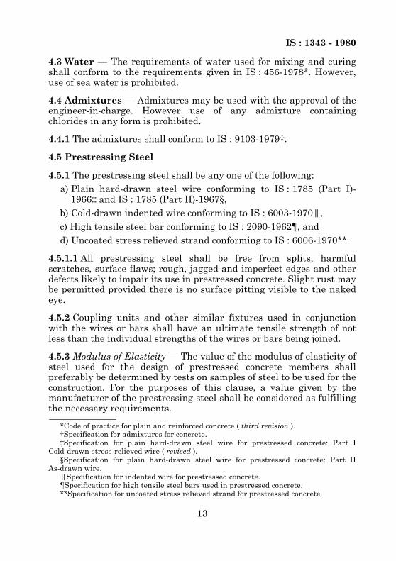
15.1 The provisions given in IS : 456-1978‡ shall apply; but theoptional test requirements of concrete and values of assumed standarddeviation shall be as given in Table 2 and Table 3 respectively. Inaddition, the requirement given in 15.2 shall apply.
*Code of practice for extreme weather concreting: Part I Recommended practice forhot weather concreting.
†Code of practice for extreme weather concreting: Part II Recommended practice forcold weather concreting.
‡Code of practice for plain and reinforced concrete ( third revision ).
TABLE 2 OPTIONAL TESTS REQUIREMENTS OF CONCRETE
GRADE OFCONCRETE
COMPRESSIVE STRENGTHON 15 cm CUBES,Min AT 7 DAYS
MODULUS OF RUPTUREBY BEAM TEST,
MIN
AT 72 ± 2 h AT 7 DAYS
(1) (2) (3) (4)
N/mm2 N/mm2 N/mm2
M 30M 35M 40M 45M 50M 55M 60
20.023.527.030.033.537.040.0
2.12.32.52.72.93.13.3
3.03.23.43.63.84.04.2
TABLE 3 ASSUMED STANDARD DEVIATION
GRADE OF CONCRETE ASSUMED STANDARD DEVIATION
(1) (2)N/mm2
M 30M 35M 40M 45M 50M 55M 60
6.06.36.67.07.47.77.8

IS : 1343 - 1980
30
15.2 Concrete Strength at Transfer — In addition to the testsrequired as per 15.1, additional cube tests should be conducted atappropriate intervals to ensure that the concrete strength in themember at transfer conforms to the design requirements. Thefrequency of sampling and number of cubes should be decided by theengineer-in-charge. The sampling of concrete should preferably be atthe point of placing and the cubes should be stored as far as possibleunder the same conditions as the concrete in the members.
16. ACCEPTANCE CRITERIA
16.1 The provisions of IS : 456-1978* shall apply.
17. INSPECTION AND TESTING OF STRUCTURES
17.1 The provisions of IS : 456-1978* shall apply, except for thefollowing:
a) For type 1 and type 2 structures ( see 19.3.2 ), if within 24 hoursof removal of the imposed load, the structure does not recover atleast 85 percent of the deflection under superimposed load, thetest may be repeated after a lapse of 72 hours. If the recovery isless than 90 percent, the structure shall be deemed to beunacceptable.
b) For type 3 structures ( see 19.3.2 ), if within 24 hours of theimposed load, the structure does not recover at least 75 percent ofthe deflection under superimposed load, the test may be repeatedafter a lapse of 72 hours. If the recovery is less than 80 percent,the structure shall be deemed to be unacceptable.
SECTION 3 GENERAL DESIGN REQUIREMENTS
18. GENERAL DESIGN REQUIREMENTS
18.1 The general design requirements for design of prestressedconcrete structures shall be as per clauses 17 to 24 of Section 3 ofIS : 456-1978* except as modified and supplemented in 18.2 to 18.6.5.
18.2 The effects of prestress shall also be taken into account inassessing loads and forces.
18.3 The deductions for prestressing tendons as in 18.3.1 shall beconsidered for the determination of area, centroid and moment ofinertia of the cross-section.
*Code of practice for plain and reinforced concrete ( third revision ).

IS : 1343 - 1980
31
18.3.1 Deductions for Prestressing Tendons — In calculating area,centroid and moment of inertia of a cross-section, deduction forprestressing tendons shall be made as follows:
a) In the case of pre-tensioned members, where the prestressingtendons are single wires distributed on the cross-section orstrands of wires of relatively small cross-sectional area,allowance for the prestressing tendons need not be made. Whereallowance is made, it shall be on the basis of (m-1) times the areaof the prestressing tendons, m being the modular ratio.
b) In the case of post-tensioned members, deductions shallinvariably be made for prestressing tendons, cable ducts orsheaths and such other openings whether they are formedlongitudinally or transversely. These deductions need not,however, be made for determining the effect of loads applied afterthe ducts, sheaths or openings have been grouted or filled withconcrete. Where such deductions are not made, a transformedarea equivalent to (m-1) times the area of the prestressing tendonshall be taken in calculation, m being the modular ratio.
NOTE — m shall be calculated as Es/Ec; for values of Es and Ec, see 4.5.3.1 and 5.2.3.1respectively. Wherever necessary, creep effects shall also be taken into consideration.
18.4 Instability During Erection — In evaluating the slendernesseffects during lifting of slender beams, the following factors requireconsideration:
a) Beam geometry,b) Location of lifting points,c) Method of lifting, andd) Tolerances in construction.
All beams, which are lifted on vertical or inclined slings, shall bechecked for lateral stability and lateral moment on account of tilting ofbeam due to inaccuracies in location of lifting points, and due to thelateral bow.For calculating the factor of safety against lateral instability γi referencemay be made to specialist literature; the factor shall not be less than two.For determining the lateral moment due to tilting, realistic valueswhich are not likely to be exceeded in practice shall be assumed for theeccentricity of lifting points and the lateral bow. The maximum tensilestress for γi/( γi – 1 ) times the lateral moment due to tilting shall notexceed 1.5 N/mm2.18.5 Prestressing Requirements18.5.1 Maximum Initial Prestress — At the time of initial tensioning,the maximum tensile stress fpi immediately behind the anchoragesshall not exceed 80 percent of the ultimate tensile strength of the wireor bar or strand.

IS : 1343 - 1980
32
18.5.2 Losses in Prestress — While assessing the stresses in concreteand steel during tensioning operations and later in service, due regardshall be paid to all losses and variations in stress resulting from creepof concrete, shrinkage of concrete, relaxation of steel, the shortening(elastic deformation) of concrete at transfer, and friction and slip ofanchorage. Unless otherwise determined by actual tests, allowance forthese losses shall be made in accordance with the values specifiedunder 18.5.2.1 to 18.5.2.6.In computing the losses in prestress when untensioned reinforcementis present, the effect of the tensile stresses developed by theuntensioned reinforcement due to shrinkage and creep shall beconsidered.18.5.2.1 Loss of prestress due to creep of concrete — The loss ofprestress due to creep of concrete under load shall be determined forall the permanently applied loads including the prestress.The creep loss due to live load stresses, erection stresses and otherstresses of short duration may be ignored. The loss of prestress due tocreep of concrete is obtained as the product of the modulus of elasticityof the prestressing steel ( see 4.5.3 ) and the ultimate creep strain ofthe concrete fibre ( see 5.2.5.1 ) integrated along the line of centre ofgravity of the prestressing steel over its entire length.The total creep strain during any specific period shall be assumed for allpractical purposes, to be the creep strain due to sustained stress equalto the average of the stresses at the beginning and end of the period.18.5.2.2 Loss of prestress due to shrinkage of concrete — The loss ofprestress due to shrinkage of concrete shall be the product of themodulus of elasticity of steel ( see 4.5.3 ) and the shrinkage strain ofconcrete ( see 5.2.4.1 ).18.5.2.3 Loss of prestress due to relaxation of steel — The relaxationlosses in prestressing steels vary with type of steel, initial prestress,age, and temperature and, therefore, shall be determined fromexperiments. When experimental values are not available, therelaxation losses may be assumed as given in Table 4.
TABLE 4 RELAXATION LOSSES FOR PRESTRESSING STEELAT 1 000 H AT 27°C
INITIAL STRESS RELAXATION LOSS(1) (2)
N/mm2
0.5 fp0.6 fp0.7 fp0.8 fp
0357090
NOTE — fp is the characteristic strength of prestressing steel.

IS : 1343 - 1980
33
For tendons at higher temperatures or subjected to large lateral loads,greater relaxation losses as specified by the engineer-in-charge shallbe allowed for. No reduction in the value of the relaxation lossesshould be made for a tendon with a load equal to or greater than therelevant jacking force that has been applied for a short time prior tothe anchoring of the tendon.18.5.2.4 Loss of prestress due to shortening of concrete — This type ofloss occurs when the prestressing tendons upon release fromtensioning devices cause the concrete to be compressed. This loss isproportional to the modular ratio and initial prestress in the concreteand shall be calculated as below, assuming that the tendons arelocated at their centroid:
a) For pretensioning, the loss of prestress in the tendons at transfershall be calculated on a modular ratio basis using the stress inthe adjacent concrete.
b) For members with post-tensioned tendons which are not stressedsimultaneously, there is a progressive loss of prestress duringtransfer due to the gradual application of the prestressing forces.This loss of prestress should be calculated on the basis of half theproduct of the stress in the concrete adjacent to the tendonsaveraged along their lengths and the modular ratio.Alternatively, the loss of prestress may be exactly computedbased on the sequence of tensioning.
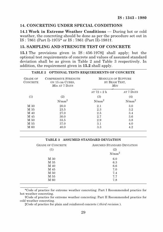
18.5.2.5 Loss of prestress due to slip in anchorage — Any loss ofprestress which may occur due to slip of wires during anchoring or dueto the strain of anchorage shall be allowed for in the design. Loss dueto slip in anchorage is of special importance with short members andthe necessary additional elongation should be provided for at the timeof tensioning to compensate for this loss.18.5.2.6 Loss of prestress due to friction — The design shall take intoconsideration all losses in prestress that may occur during tensioningdue to friction between the prestressing tendons and the surroundingconcrete or any fixture attached to the steel or concrete.For straight or moderately curved structures, with curved or straightcables, the value of prestressing force Px at a distance x metres fromtensioning end and acting in the direction of the tangent to the curve ofthe cable, shall be calculated as below:
Px = Poe– ( µα + kx )
wherePo = prestressing force in the prestressed steel at the tensioning
end acting in the direction of the tangent to the curve of thecable,
IS : 1343 - 1980
34
18.6 Considerations Affecting Design Details
18.6.1 Transmission Zone in Pre-tensioned Members18.6.1.1 Transmission length — The considerations affecting thetransmission length shall be the following:
a) The transmission length depends on a number of variables, themost important being the strength of concrete at transfer, thesize and type of tendon, the surface deformations of the tendon,and the degree of compactness of the concrete around the tendon.
b) The transmission length may vary depending on the siteconditions and therefore should be determined from tests carriedout under the most unfavourable conditions. In the absence ofvalues based on actual tests, the following values may be used,provided the concrete is well-compacted, and its strength attransfer is not less than 35 N/mm2 and the tendon is releasedgradually:
α = cumulative angle in radians through which the tangent to thecable profile has turned between any two points underconsideration,
µ = coefficient of friction in curve; unless otherwise proved bytests, µ may be taken as:0.55 for steel moving on smooth concrete,0.30 for steel moving on steel fixed to duct, and0.25 for steel moving on lead,
k = coefficient for wave effect varying from 15 × 10–4 to 50 × 10–4
per metre.NOTE 1 — Expansion of the equation for Px for small values of ( µα + kx ) may bePx = Po ( 1 – µα – kx ).
NOTE 2 — In circular constructions, where circumferential tendons are tensioned byjacks, values of µ for calculating friction may be taken as:
0.45 for steel moving in smooth concrete,
0.25 for steel moving on steel bearers fixed to the concrete, and
0.10 for steel moving on steel rollers.
NOTE 3 — The effect of reverse friction shall be taken into consideration in such caseswhere the initial tension applied to a prestressing tendon is partially released andaction of friction in the reverse direction causes an alteration in the distribution ofstress along the length of the tendon.
1) For plain and indented wire 100φ2) For crimped wires 65φ3) Strands 30φ
NOTE 1 — φ is the diameter of the tendon.
NOTE 2 — The recommended values of transmission length apply to wires ofdiameter not exceeding 5 mm and strands of diameter not exceeding 18 mm.
IS : 1343 - 1980
35
c) The development of stress in the tendon may be assumed to varyparabolically along the length of the member.
d) For general guidance, it is recommended that one-half of thetransmission length shall overhang the support in a simplysupported beam. Where there is end-fixing, the whole of thetransmission length shall overhang.
18.6.2 End Zone18.6.2.1 Bearing stress
a) On the areas immediately behind external anchorages, thepermissible unit bearing stress on the concrete, after accountingfor all losses due to relaxation of steel, elastic shortening, creep ofconcrete, slip and/or seating of anchorages, etc, shall not exceed
0.48 fci or 0.8 fci whichever is smaller, where fci is the cube
strength at transfer, Abr is the bearing area and Apun is thepunching area.
b) During tensioning, the allowable bearing stress specified in a)may be increased by 25 percent, provided that this temporaryvalue does not exceed fci.
c) The bearing stress specified in (a) and (b) for permanent andtemporary bearing stress may be increased suitably if adequatehoop reinforcement complying with IS : 456-1978* is provided atthe anchorages.
d) When the anchorages are embedded in concrete, the bearingstress shall be investigated after accounting for the surfacefriction between the anchorage and the concrete.
e) The effective punching area shall generally be the contact area ofthe anchorage devices which, if circular in shape, shall bereplaced by a square of equivalent area. The bearing area shall bethe maximum area of that portion of the member which isgeometrically similar and concentric to the effective punchingarea.
f) Where a number of anchorages are used, the bearing area Abrshall not overlap. Where there is already a compressive stressprevailing over the bearing area, as in the case of anchorageplaced in the body of a structure, the total stress shall not exceedthe limiting values specified in (a), (b) and (c). For stage stressingof cables, the adjacent unstressed anchorages shall be neglectedwhen determining the bearing area.
*Code of practice for plain and reinforced concrete ( third revision ).
Abr
Apun-------------

IS : 1343 - 1980
36
18.6.2.2 Bursting tensile forcesa) The bursting tensile forces in the end blocks, or regions of bonded
post-tensioned members, should be assessed on the basis of thetendon jacking load. For unbonded members, the bursting tensileforces should be assessed on the basis of the tendon jacking loador the load in the tendon at the limit state of collapse, whicheveris greater ( see Appendix B ).The bursting tensile force, Fbst existing in an individual squareend block loaded by a symmetrically placed square anchorage orbearing plate, may be derived from the equation below:
b) The force Fbst will be distributed in a region extending from 0.1 yoto yo from the loaded face of the end block. Reinforcementprovided to sustain the bursting tensile force may be assumed tobe acting at its design strength (0.87 times characteristicstrength of reinforcement) except that the stress should belimited to a value corresponding to a strain of 0.001 when theconcrete cover to the reinforcement is less than 50 mm.
c) In rectangular end blocks, the bursting tensile forces in the twoprincipal directions should be assessed on the basis of 18.6.2.2.When circular anchorage or bearing plates are used, the side of theequivalent square area should be used. Where groups of anchoragesor bearing plates occur, the end blocks should be divided into aseries of symmetrically loaded prisms and each prism treated in theabove manner. For designing end blocks having a cross-sectiondifferent in shape from that of the general cross-section of the beam,reference should be made to specialist literature.
d) Compliance with the requirements of (a), (b) and (c) will generallyensure that bursting tensile forces along the load axis areprovided for. Alternative methods of design which makeallowance for the tensile strength of the concrete may be used, inwhich case reference should be made to specialist literature.
e) Consideration should also be given to the spalling tensile stressesthat occur in end blocks where the anchorage or bearing platesare highly eccentric; these reach a maximum at the loaded face.
whereFbst = bursting tensile force,
Pk = load in the tendon assessed as above,ypo = side of loaded area, andyo = side of end block.
Fbst
Pk----------- 0.32 0.3
ypo
yo--------–=

IS : 1343 - 1980
37
18.6.3 Detailing of Reinforcement in Prestressed Concrete18.6.3.1 The detailing of reinforcement in prestressed concrete shallgenerally conform to the requirements given in IS : 456-1978*. Inaddition, the requirements of 18.6.3.2 and 18.6.3.3 shall be satisfied.18.6.3.2 Transverse reinforcement
a) The amount and spacing of transverse reinforcement shall begoverned by shear and torsion considerations. It is, however,desirable to provide transverse reinforcement in the web whenthe web is thin and cables are located in the web.
b) In case of all members subjected to dynamic loading, webs shallbe provided with transverse reinforcement, not less than 0.3percent of the sectional area of the web in plan. This percentageof reinforcement may be reduced to 0.2 percent in members wherethe depth of the web is not more than four times the thickness ofthe web. These values may be reduced to 0.2 and 0.15 percentrespectively when high strength reinforcement is used.
c) In case of members not subjected to dynamic loading,reinforcement shall be provided when the depth of the web ismore than 4 times the thickness. Such reinforcement shall not beless than 0.1 percent of the sectional area of the web in plan. Thereinforcement shall be spaced at a distance not greater than theclear depth of the web and the size of such reinforcement shall beas small as possible.
d) Reinforcement in the form of links or helix shall be providedperpendicular to the line of heavy compression or shock loading toresist the induced tensile stresses.
18.6.3.3 Longitudinal reinforcementa) A minimum longitudinal reinforcement of 0.2 percent of the total
concrete area shall be provided in all cases except in the case ofpretensioned units of small sections. This reinforcement may bereduced to 0.15 percent in the case of high yield strengthdeformed reinforcement. The percentage of steel provided, bothtensioned and untensioned taken together, should be sufficient sothat when the concrete in the precompressed tensile zone cracks,the steel is in a position to take up the additional tensile stresstransferred on to it by the cracking of the adjacent fibres ofconcrete and a sudden failure is avoided.
b) When the depth of the web exceeds 50 cm, longitudinaldistribution reinforcement not less than 0.05 percent of the areaof the web shall be provided on each face. The spacing of theindividual bars of such reinforcement shall not exceed 20 cm.
*Code of practice for plain and reinforced concrete ( third revision ).

IS : 1343 - 1980
38
c) All untensioned longitudinal reinforcement shall be restrained inthe lateral direction.
18.6.4 Continuity — In the design of continuous prestressed concretestructures, due consideration shall be given to the effects of thesupport restraints on both the external moment and the moment dueto prestressing.18.6.5 Butted Assembly — Where a butted assembly is used, or wherelike conditions of abuttal are employed, proper provision shall be madeto transfer all shear stresses. Wherever the shear stresses exceed thelimits specified under 22.4, this provision shall include keying of allabutting faces.
SECTION 4 STRUCTURAL DESIGN : LIMITSTATE METHOD
19. SAFETY AND SERVICEABILITY REQUIREMENTS
19.1 Limit State Design — The structural design shall be based onlimit state concepts. In this method of design, the structure shall bedesigned to withstand safely all loads liable to act on it throughout itslife; it shall also satisfy the serviceability requirements, such aslimitations on deflection and cracking. The acceptable limit for thesafety and serviceability requirements before failure occurs is called a‘Limit State’. The aim of design is to achieve acceptable probabilitiesthat the structure will not become unfit for the use for which it isintended, that is, that it will not reach a limit state.19.1.1 All relevant limit states shall be considered in design to ensurean adequate degree of safety and serviceability. In general, thestructure shall be designed on the basis of the most critical limit stateand shall be checked for other limit states.19.1.2 For ensuring the specified objective, the design should be basedon characteristic values for material strengths and applied loads,which take into account the variations in the material strengths and inthe loads to be supported. The characteristic values should be based onstatistical data if available; where such data are not available, theyshould be based on experience. The ‘design values’ are derived fromthe characteristic value through the use of partial safety factors, onefor material strengths and the other for loads. In the absence of specialconsiderations, these factors should have the values given in 20.4according to the material, the type of loading and the limit state beingconsidered.19.2 Limit State of Collapse — The limit state of collapse of thestructure or part of the structure could be assessed from rupture of one

IS : 1343 - 1980
39
or more critical sections and from buckling due to elastic or plasticinstability (including the effects of sway where appropriate) oroverturning. The resistance to bending, shear, torsion and axial loadsat every section shall not be less than appropriate value at that sectionproduced by the probable most unfavourable combination of loads onthe structure using the appropriate partial safety factors.19.3 Limit States of Serviceability
19.3.1 Limit State of Serviceability : Deflection — The deflection of astructure or part thereof shall not adversely affect the appearance orefficiency of the structure or finishes or partitions. The deflection shallgenerally be limited to the following:
a) The final deflection, due to all loads including the effects oftemperature, creep and shrinkage and measured from the as-castlevel of the supports of floors, roofs and all other horizontalmembers, should not normally exceed span/250.
b) The deflection including the effects of temperature, creep andshrinkage occurring after erection of partitions and theapplication of finishes should not normally exceed span/350 or20 mm whichever is less.
c) If finishes are to be applied to prestressed concrete members, thetotal upward deflection should not exceed span/300, unlessuniformity of camber between adjacent units can be ensured.
19.3.2 Limit State of Serviceability : Cracking — Cracking of concreteshall not affect the appearance or durability of the structure. Thecriteria of limit state of cracking for the three types of prestressedconcrete members shall be as follows:
a) For type 1, no tensile stresses.b) For type 2, tensile stresses are allowed but no visible cracking.c) For type 3, cracking is allowed, but should not affect the
appearance or durability of the structure; the acceptable limits ofcracking would vary with the type of structure and environmentand will vary between wide limits and the prediction of absolutemaximum width is not possible.
NOTE — For design of type 3 members, as a guide, the following may be regarded asreasonable limits.
The surface width of cracks should not, in general, exceed 0.1 mm for membersexposed to a particularly aggressive environment such as the severe category inAppendix A and not exceeding 0.2 mm for all other members.
19.3.3 The flexural tensile stress at any section of the structure, bothat transfer and under the most unfavourable combination of designloads, shall satisfy the criteria for the corresponding type of structure.

IS : 1343 - 1980
40
19.3.4 Limit State of Serviceability : Maximum Compression — Thecompressive stresses both at transfer and under design loads shall belimited to the values given in 22.8 for all types of structures.19.3.5 Other Limit States — Structures designed for unusual or specialfunctions shall comply with any relevant additional limit statesconsidered appropriate to that structure.
20. CHARACTERISTIC AND DESIGN VALUES AND PARTIAL SAFETY FACTORS
20.1 Characteristic Strength of Materials — The term‘characteristic stress’ means that value of the strength of the materialbelow which not more than 5 percent of the test results are expected tofall. The characteristic strength for concrete shall be in accordancewith Table 1, modified by 5.2.1 regarding increase in concrete strengthwith age. Until the relevant Indian Standard Specifications forprestressing and reinforcing steel are modified to include the conceptof characteristic strength, the characteristic strength shall be assumedas the minimum ultimate tensile stress/breaking load for prestressingsteel and as the minimum yield/0.2 percent proof stress for reinforcingsteel, specified in the relevant Indian Standard Specifications.20.2 Characteristic Loads — The term ‘characteristic load’ meansthat value of load which has a 95 percent probability of not beingexceeded during the life of the structure. Since data are not availableto express loads in statistical terms, for the purpose of this code, thedead loads given in IS : 1911-1967*, live and wind loads given inIS : 875-1964† and seismic forces given in IS : 1893-1975‡ shall beassumed as the characteristic loads.20.3 Design Values
20.3.1 Materials — The design strength of the materials, fd is given by
fd =
20.3.2 Loads — The design load, Fd is given byFd = Fγf
*Schedule of unit weights of building materials ( first revision ).†Code of practice for structural safety of buildings : Loading standards ( revised ).‡Criteria for earthquake resistant design of structures ( third revision ).
wherefd = characteristic strength of the material ( see 20.1 ), andγm = partial safety factor appropriate to the material and the limit
state being considered ( see 20.4 ).
fγm------

IS : 1343 - 1980
41
whereF = characteristic load ( see 20.2 ), andγf = partial safety factor appropriate to the nature of loading and the
limit state being considered ( see 20.4 ).
20.3.3 Consequences of Attaining Limit State — Where theconsequences of a structure attaining a limit state are of a serious naturesuch as huge loss of life and disruption of the economy, higher values forγm and γf than those given under 20.4.1 and 20.4.2 may be applied.
20.4 Partial Safety Factors
20.4.1 Partial Safety Factor γm for Material Strength
20.4.1.1 When assessing the strength of a structure or structuralmember for the limit state of collapse, the values of partial safetyfactor γm should be taken as 1.5 for concrete and 1.15 for steel.
NOTE — γm values are already incorporated in the equations and tables given in thiscode.
20.4.1.2 When assessing the deflection, the material properties suchas modulus of elasticity of concrete should be taken as those associatedwith the characteristic strength of the material and safety factor shallnot be applied.
20.4.2 Partial Safety Factor γf for Loads — The value of γf given inTable 5 shall normally be used.
21. ANALYSIS
21.1 Analysis of Structure — Methods of analysis as in IS : 456-1978*shall be used. The material strength to be assumed shall becharacteristic values in the determination of elastic properties ofmembers, irrespective of the limit state being considered. Redistributionof the calculated moments may be made as given in 21.1.1.
21.1.1 Redistribution of Moments in Continuous Beams and Frames —The redistribution of moments may be carried out satisfying thefollowing conditions:
a) Equilibrium between the internal forces and the external loads ismaintained.
b) The ultimate moment of resistance provided at any section of amember is not less than 80 percent of the moment at that section,obtained from an elastic maximum moment diagram covering allappropriate combinations of loads.
*Code of practice for plain and reinforced concrete ( third revision ).

IS : 1343 - 1980
42
c) The elastic moment at any section in a member due to aparticular combination of loads shall not be reduced by more than20 percent of the numerically largest moment given anywhere bythe elastic maximum moment diagram for the particularmember, covering all appropriate combination of loads.
d) At sections where the moment capacity after redistribution is lessthan that from the elastic maximum moment diagram, thefollowing relationship shall be satisfied:
e) In structures in which the structural frame provides the lateralstability, the reduction in moment allowed by condition given in21.1.1 (c) shall be restricted to 20 percent for structures up to 4storeys in height and 10 percent for structures over 4 storeys inheight.
21.1.2 Analysis of Slabs Spanning in Two Directions at Right Angles —In general, the provisions of IS : 456-1978* shall apply.
TABLE 5 VALUES OF PARTIAL SAFETY FACTOR γf FOR LOADS( Clause 20.4.2 )
LOAD COMBINATION
LIMIT STATE OFCOLLAPSE
LIMIT STATES OF SERVICEABILITY
DL LL WLDL LL WL
(1) (2) (3) (4) (5) (6) (7)
DL + LL 1.5 — 1.0 1.0 —DL + WL 1.5 or 0.9
( see Note 2 )— 1.5 1.0 — 1.0
DL + LL + WL 1.2 1.0 0.8 0.8NOTE 1 — DL is the dead load, LL is the live load and WL is the wind load.NOTE 2 — This value of 0.9 is to be considered when stability against overturning orstress reversal is critical.NOTE 3 — While considering earthquake effects, substitute EL for WL.NOTE 4 — For the limit states of serviceability, the values of γf given in this table areapplicable for short-term effects. While assessing the long-term effects due to creep, thedead load and that part of the live load likely to be permanent may only be considered.
wherexu = depth of neutral axis,d = effective depth, and
δM = percentage reduction in moment.
*Code of practice for plain and reinforced concrete ( third revision ).
xu
d------
δM100----------+ 0.5≤

IS : 1343 - 1980
43
22. LIMIT STATE OF COLLAPSE22.1 Limit State of Collapse : Flexure22.1.1 Assumptions — Design for the limit state of collapse in flexureshall be based on the assumptions given below:
a) Plane sections normal to the axis remain plane after bending.b) The maximum strain in concrete at the outermost compression
fibre is taken as 0.003 5 in bending.c) The relationship between the compressive stress distribution in
concrete and the strain in concrete may be assumed to berectangle, trapezoid, parabola or any other shape which results inprediction of strength in substantial agreement with the resultsof tests. An acceptable stress-strain curve is given in Fig. 3. Fordesign purposes, the compressive strength of concrete in thestructure shall be assumed to be 0.67 times the characteristicstrength. The partial safety factor γm = 1.5 shall be applied inaddition to this.
NOTE — For the stress-strain curve in Fig. 3, the design stress block parameters forrectangular section are as follows ( see Fig. 4 ) :Area of stress block = 0.36fck . xuDepth of centre of compressive force from the extreme fibre in compression = 0.42 xu
d) The tensile strength of the concrete is ignored.e) The stresses in bonded prestressing tendons, whether initially
tensioned or untensioned, and in additional reinforcement arederived from the representative stress-strain curve for the type ofsteel used given by the manufacturer or typical curves given inFig. 5 for prestressing tendons and in IS : 456-1978* forreinforcement. For design purposes, the partial safety factor γmequal to 1.15 shall be applied.
f) If tendons are unbonded in post-tensioned members, the stress inthe tendons may be obtained from a rigorous analysis or fromtests.
22.1.2 Design Formulae — In the absence of an analysis based on theassumptions given in 22.1.1, the moment of resistance of rectangularsections and flanged sections in which the neutral axis lies within theflange may be obtained by the procedure given in Appendix B.For flanged sections in which the neutral axis lies outside the flange, themoment of resistance shall be determined using assumptions in 22.1.1.
wherefck = characteristic compressive strength of concrete, andxu = depth of neutral axis.
*Code of practice for plain and reinforced concrete ( third revision ).

IS : 1343 - 1980
44
FIG. 3 STRESS STRAIN CURVE FOR CONCRETE
FIG. 4 STRESS BLOCK PARAMETERS

IS : 1343 - 1980
45
FIG. 5 REPRESENTATIVE STRESS STRAIN CURVES FOR PRESTRESSING STEELS

IS : 1343 - 1980
46
22.2 Limit State of Collapse : Compression — Prestressed concretecompression members in framed structures, where the mean stress in theconcrete section imposed by tendons is less than 25 N/mm2, may beanalysed as reinforced concrete compression members in accordance withIS : 456-1978*; in other cases specialist literature may be referred to.22.3 Limit State of Collapse : Tension — Tensile strength of thetension members shall be based on the design strength (0.87 timescharacteristic strength of prestressing tendons) and the strengthdeveloped by any additional reinforcement. The additionalreinforcement may usually be assumed to be acting at its design stress(0.87 times characteristic strength of reinforcement); in special cases itmay be necessary to check the stress in the reinforcement using straincompatibility.22.4 Limit State of Collapse : Shear — The ultimate shearresistance of the concrete alone, Vc, should be considered at bothsections uncracked and cracked in flexure, the lesser value taken and,if necessary, shear reinforcement provided.22.4.1 Sections Uncracked in Flexure — The ultimate shear resistanceof a section uncracked in flexure, Vc = Vco, is given by:
Vco = 0.67 bD
In flanged members where the centroidal axis occurs in the flange, theprincipal tensile stress should be limited to 0.24 at theintersection of the flanged web; in this calculation, 0.8 of the stress dueto prestress at this intersection may be used, in calculating Vco.For a section uncracked in flexure and with inclined tendons orvertical prestress, the component of prestressing force normal to thelongitudinal axis of the member may be added to Vco.22.4.2 Sections Cracked in Flexure — The ultimate shear resistance ofa section cracked in flexure, Vc = Vcr, is given by:
Vcr =
*Code of practice for plain and reinforced concrete ( third revision ).
whereb = breadth of the member which for T, I and L beams should be
replaced by breadth of the rib bw,D = overall depth of the member,ft = maximum principal tensile stress given by 0.24 taken as
positive where fck is the characteristic compressive strength ofconcrete, and
fcp = compressive stress at centroidal axis due to prestress taken aspositive.
ft2 0.8 fcpft+
fck
fck
1 0.55 fpe
fp-------–
ζo bd Mo VM-----+

IS : 1343 - 1980
47
wherefpe = effective prestress after all losses have occurred, which
shall not be put greater than 0.6 fp,fp = characteristic strength of prestressing steel,ζc = ultimate shear stress capacity of concrete obtained from
Table 6,b = breadth of the member, which, for flanged sections,
shall be taken as the breadth of the web bw,d = distance from the extreme compression-fibre to the
centroid of the tendons at the section considered,Mo = moment necessary to produce zero stress in the concrete
at the depth, given by:
Mo = 0.8 fpt
where fpt is the stress due to prestress only at depth dand distance y from the centroid of the concrete sectionwhich has second moment of area I, and
V and M = shear force and bending moment respectively, at thesection considered due to ultimate loads.
Vcr should be taken as not less than 0.1 bd .
TABLE 6 DESIGN SHEAR STRENGTH OF CONCRETE, ζc, N/mm2
( Clause 22.4.2 )
100CONCRETE GRADE
M 30 M 35 M 40 and Above
(1) (2) (3) (4)
0.250.500.751.001.251.501.752.002.252.502.753.00
0.370.500.590.660.710.760.800.840.880.910.940.96
0.370.500.590.670.730.780.820.860.900.930.960.99
0.380.510.600.680.740.790.840.880.920.950.981.01
NOTE — Ap is the area of prestressing tendon.
IY----
fck
Apbd-------

IS : 1343 - 1980
48
The value of Vcr calculated at a particular section may be assumed tobe constant for a distance equal to d/2, measured in the direction ofincreasing moment, from that particular section.For a section cracked in flexure and with inclined tendons, thecomponent of prestressing forces normal to the longitudinal axis of themember should be ignored.22.4.3 Shear Reinforcement22.4.3.1 When V, the shear force due to the ultimate loads, is less thanVc, the shear force which can be carried by the concrete, minimum shearreinforcement should be provided in the form of stirrups such that:
However, shear reinforcement need not be provided in the followingcases:
a) where V is less then 0.5 Vc, andb) in members of minor importance.
22.4.3.2 When V exceeds Vc, shear reinforcement shall be providedsuch that:
In rectangular beams, at both corners in the tensile zone, a stirrupshould pass around a longitudinal bar, a tendon or a group of tendons thaving a diameter not less than the diameter of the stirrup. The depthdt is then taken as the depth from the extreme compression fibreeither to the longitudinal bars or to the centroid of the tendonswhichever is greater.The spacing of stirrups along a member should not exceed 0.75 dt nor 4times the web thickness for flanged members. When V exceeds 1.8 Vc,the maximum spacing should be reduced to 0.5 dt. The lateral spacingof the individual legs of the stirrups provided at a cross section shouldnot exceed 0.75 dt.
whereAsv = total cross-sectional area of stirrup legs effective in shear,
b = breadth of the member which for T, I and L beams should betaken as the breadth of the rib, bw,
sv = stirrup spacing along the length of the member, andfv = characteristic strength of the stirrup reinforcement which
shall not be taken greater than 415 N/mm2.
Asv
bsv--------- 0.4
0.87fv----------------=
Asv
sv---------
V Vc–
0.87 fvdt------------------------=

IS : 1343 - 1980
49
22.4.4 Maximum Shear Forces — In no circumstances should theshear force V, due to ultimate loads, exceed the appropriate valuesgiven in Table 7 multiplied by bd.
22.5 Limit State of Collapse: Torsion
22.5.1 General — In general, where the torsional resistance orstiffness of members has not been taken into account in the analysis ofthe structure, no specific calculations for torsion will be necessary,adequate control in torsional cracking being provided by the requirednominal shear reinforcement. Where the torsional resistance orstiffness of members is taken into account in the analysis, themembers shall be designed for torsion.
22.5.2 Application of Design Rules for Torsion — The design rules laiddown in 22.5.3 to 22.5.5 apply to:
a) beams of solid rectangular cross-section ( D > b ),b) hollow rectangular beams with D > b and with a wall thickness
t ≥ o/4, andc) T-beam and I-beams.
In all these cases the average intensity of prestress in the concreteshall be less than 0.3 fck.
22.5.3 Longitudinal Reinforcement
22.5.3.1 The longitudinal reinforcement shall be designed to resist anequivalent ultimate bending moment Me1 given by:
Me1 = M + Mt
TABLE 7 MAXIMUM SHEAR STRESS
Concrete Grade M 30 M 35 M 40 M 45 M 50 M 55 and overMaximumShear Stress,
N/mm2
3.5 3.7 4.0 4.3 4.6 4.8
where
M = applied ultimate bending moment at the cross-section actingin combination with T,
Mt = , the sign of Mt being the same as that of M,
D = overall depth of the beam, andb = breadth of the member which for T and I beams shall be
taken as the breadth of the web, bw.
T 1 2Db
--------+

IS : 1343 - 1980
50
22.5.3.2 Where the numerical value of M is less than that of Mt, themember shall also be designed to withstand a moment Me2 given by:
Me2 = Mt – M,the moment Me2 being taken as acting in the opposite sense to themoment M.22.5.3.3 Where the numerical value of M is less than or equal to that ofMt, the beam shall be designed to withstand an equivalent transversebinding moment Me3 (not acting simultaneously with Me1), given by:
Me3 =
and acting about an axis at right angles to the axis of M, where x1 isthe smaller dimension of a closed hoop used as torsional shearreinforcement and e is as defined in 22.5.4.1.22.5.4 Transverse Reinforcement22.5.4.1 Torsional moment and shear carried by concrete — Thereduced torsional moment carried by the concrete Tc1 is given by:
Tc1 =
where
Tc =
e =
ec =
λp =
In the above expressions,Tc = torsional moment carried by concrete,b = breadth of the member, which for T and I beams shall be taken
as the breadth of the web, bw,D = overall depth of beam,fck = characteristic compressive strength of concrete,T = torsional moment applied to a cross-section under ultimate
load conditions,
Mt 1x12e------+
2 1 2bD-------+
1 2Db
--------+------------------
Tc ee ec+--------------
Σ1.5 b2D 1 b30------–
λp fck
TV----
Tc
Vc------
112 fcp
fck----------------+

IS : 1343 - 1980
51
22.5.4.2 The shear force carried by the concrete Vc1 is given by:
Vc1 =
whereVc = smaller of Vco and Vcr obtained as in 22.4.1 and 22.4.2.
22.5.4.3 Design of transverse reinforcement — The area ofcross-section, Asv of the closed stirrup enclosing the corner longitudinalbars shall be taken as the larger of the following two values:
Asv =
and Asv = Av + 2 ATwhere
Av =
AT =
22.5.4.4 Minimum reinforcement — The value of Asv shall not be takenlesser than that given by:
V = shearing force at a cross section calculated for the specifiedultimate loads,
Vc = theoretical shear strength at a cross section, assuming themost unfavourable conditions for inclined cracking, that is,smaller of Vco and Vcr ( see 22.4.1 and 22.4.2 ), and
fcp = average intensity of effective prestress in concrete.
In the above expressions,Mt = as defined in 22.5.3.1,sv = spacing of the stirrup reinforcement,b1 = centre to centre distance between corner bars in the direction
of the width,d1 = centre to centre distance between corner bars in the direction
of the depth,fv = characteristic strength of shear reinforcement,
V is as defined in 22.5.4.1,Vc1 is as defined in 22.5.4.2, andT and Tc1 are as defined in 22.5.4.1.
Vce
e ec+--------------
Mtsv1.5 b1d1 fv------------------------------
V Vc1–( ) sv0.87 fvd1
--------------------------------
T Tc1 –( ) sv0.87 b1d1fv
------------------------------------
Asvbsv--------- 0.4
0.87 fv------------------=

IS : 1343 - 1980
52
There shall be at least one longitudinal bar not less than 12 mm indiameter in each corner of the stirrups.22.5.5 Distribution of Torsion Reinforcement — When a member isdesigned for torsion, torsion reinforcement shall be provided as below:
a) All transverse reinforcement provided for torsion shall be in theform of closed stirrups perpendicular to the axis of the members;
b) The spacing, sv, of the stirrups shall not exceed ( x1 + y1 )/4 or200 mm whichever is smaller, where x1 and y1 are respectivelyshort and long dimensions of the stirrup;
c) Each end of the bar forming the stirrup shall be anchored inaccordance with IS : 456-1978*; and
d) Torsional reinforcement shall be continued to a distance not lessthan ( D + bw ) beyond the point at which it is no longer thantheoretically required, where D is the overall depth and bw is theeffective width of the web of a flanged member.
22.6 Limit State of Serviceability : Deflection22.6.1 Type 1 and Type 2 Members22.6.1.1 Short-term deflection — The instantaneous deflection due todesign loads may be calculated using elastic analysis based on theuncracked section and the modulus of elasticity of concrete as givenin 5.2.3.22.6.1.2 Long-term deflection — The total long-term deflection due tothe prestressing force, dead load and any sustained imposed load maybe calculated using elastic analysis, taking into account the effects ofcracking and of creep and shrinkage ( see 5.2.4 and 5.2.5 ). Dueallowance shall be made for the loss of prestress ( see 18.5.2 ) after theperiod considered. The deflections should comply with the limits givenin 19.3.1.22.6.2 Type 3 Members — Where the permanent load is less than orequal to 25 percent of the design imposed load, the deflection may becalculated as in 22.6.1.1. When the permanent load is more than 25percent of the design imposed load, the vertical deflection limits forbeams and slabs may generally be assumed to be satisfied providedthat the span to effective depth ratios are not greater than the valuesobtained as below:
a) Basic values of span to effective depth ratios for spans up to 10 m:
*Code of practice for plain and reinforced concrete ( third revision ).
Cantilever 7Simply supported 20Continuous 26

IS : 1343 - 1980
53
b) For spans above 10 m, the values in (a) may be multiplied by10/span in metres, except for cantilever in which case deflectioncalculations should be made.
22.7 Limit State of Serviceability: Cracking
22.7.1 In members made up of precast units, no tension shall beallowed at any stage at mortar or concrete joints. For a member whichis free of joints, the tensile stress shall not exceed the values specifiedbelow for the 3 types of members.
a) Type 1 — No tensile stress.b) Type 2 — The tensile stress shall not exceed 3 N/mm2. However,
where part of the service loads is temporary in nature, this valuemay be exceeded by 1.5 N/mm2, provided under the permanentcomponent of the service load the stress remains compressive.
c) Type 3 — For type 3 members in which cracking is permitted, itmay be assumed that the concrete section is uncracked, and thathypothetical tensile stresses exist at the maximum size of cracks.The hypothetical tensile stresses for use in these calculations formembers with either pre-tensioned or post-tensioned tendons aregiven in Table 8, modified by coefficients given in Fig. 6.
NOTE — When additional reinforcement is distributed within the tension zone andpositioned close to the tension face of concrete, the hypothetical tensile stresses maybe increased by an amount which is proportional to the cross-sectional areas of theadditional reinforcement expressed as a percentage of the cross-sectional area of theconcrete. For 1 percent of additional reinforcement, the stress may be increased by4 N/mm2 for members with pre-tensioned and grouted post-tensioned tendons and by3 N/mm2 for other members. For other percentages of additional reinforcement thestresses may be increased in proportion excepting that the total hypothetical tensilestress shall not exceed 0.25 times the characteristic compressive strength of concrete.
TABLE 8 HYPOTHETICAL FLEXURAL TENSILE STRESSESFOR TYPE 3 MEMBERS
TYPE OF TENDONS LIMITING CRACK WIDTH
STRESS OF CONCRETE FOR GRADE
M 30 M 35 M 40 M 45 M 50 and above(1) (2) (3) (4) (5) (6) (7)
mm
Pre-tensioned tendons 0.10.2
——
——
4.15.0
4.45.4
4.85.8
Grouted post-tensionedtendons
0.10.2
3.23.8
3.64.4
4.15.0
4.45.4
4.85.8
Pre-tensioned tendonsdistributed in the tensilezone and positionedclose to the tension facesof concrete
0.10.2
——
——
5.36.3
5.86.8
6.37.3

IS : 1343 - 1980
54
22.8 Limit State of Serviceability: Maximum Compression
22.8.1 Maximum Stress Under Service Conditions22.8.1.1 Compressive stress in flexure — The maximum permissiblecompressive stress, prestress and service loads after deduction of thefull losses in the specified prestress shall be determined by a straightline relation as in Fig. 7; but different stress limits shall apply to theconcrete of the structure depending on whether it falls in a part of thesection where the compressive stresses are not likely to increase inservice (Zone I) or in part of the section where the compressive stressesare likely to increase in service (Zone II) ( see Fig. 7 ).For Zone I, the straight line relation of permissible stress shall bedetermined by the straight line joining a point given by a permissiblestress of 0.41 fck for concrete of Grade M 30 to another point given by apermissible stress of 0.35 fck for concrete of Grade M 60.For Zone II, the determining points of the graph shall be reduced to0.34 fck and 0.27 fck respectively.22.8.1.2 Stress in direct compression — Except in the partsimmediately behind the anchorage, the maximum stress in directcompression shall be limited to 0.8 times the permissible stressobtained from 22.8.1.1.
FIG. 6 DEPTH FACTORS FOR TENSILE STRESSES FOR TYPE 3 MEMBERS
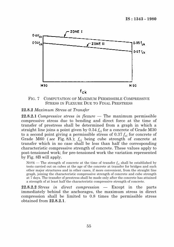
IS : 1343 - 1980
55
22.8.2 Maximum Stress at Transfer
22.8.2.1 Compressive stress in flexure — The maximum permissiblecompressive stress due to bending and direct force at the time oftransfer of prestress shall be determined from a graph in which astraight line joins a point given by 0.54 fci for a concrete of Grade M30to a second point giving a permissible stress of 0.37 fci for concrete ofGrade M60 ( see Fig. 8A ); fci being cube strength of concrete attransfer which in no case shall be less than half the correspondingcharacteristic compressive strength of concrete. These values apply topost-tensioned work; for pre-tensioned work the variation representedby Fig. 8B will apply.
NOTE — The strength of concrete at the time of transfer fci shall be established bytests carried out on cubes at the age of the concrete at transfer for bridges and suchother major structures and in other cases, if more convenient, from the straight linegraph, joining the characteristic compressive strength of concrete and cube strengthat 7 days. The transfer of prestress shall be made only after the concrete has attaineda strength of at least half the characteristic compressive strength of concrete.
22.8.2.2 Stress in direct compression — Except in the partsimmediately behind the anchorages, the maximum stress in directcompression shall be limited to 0.8 times the permissible stressobtained from 22.8.2.1.
FIG. 7 COMPUTATION OF MAXIMUM PERMISSIBLE COMPRESSIVE STRESS IN FLEXURE DUE TO FINAL PRESTRESS

IS : 1343 - 1980
56
FIG. 8 COMPUTATION OF MAXIMUM PERMISSIBLE COMPRESSIVE STRESS IN FLEXURE AT TRANSFER

IS : 1343 - 1980
57
A P P E N D I X A( Clauses 7.2 and 19.3.2 )
REQUIREMENTS FOR DURABILITY
A-1. Minimum cement contents for different exposures and sulphateattack are given in Tables 9 and 10 for general guidance.
A-2. To minimize the chances of deterioration of concrete from harmfulchemical salts, the levels of such harmful salts in concrete coming fromthe concrete materials, that is, cement, aggregates, water andadmixtures as well as by diffusion from the environments should belimited. Generally, the total amount of chlorides (as Cl–) and the totalamount of soluble sulphates (as SO3
–) in the concrete at the time ofplacing should be limited to 0.06 percent by mass of cement and 4percent by mass of cement respectively.
TABLE 9 MINIMUM CEMENT CONTENT REQUIRED IN CEMENT CONCRETE TO ENSURE DURABILITY UNDER SPECIFIED
CONDITIONS OF EXPOSURE
EXPOSURE PRESTRESSED CONCRETE
Minimum Cement Content kg/m3
Maximum Water- Cement Ratio
Mild — For example, completely protectedagainst weather, or aggressiveconditions, except for a brief periodof exposure to normal weatherconditions during construction
300 0.65
Moderate — For example, sheltered from heavyand wind driven rain and againstfreezing, whilst saturated withwater, buried concrete in soil andconcrete continuously under water
300 0.55
Severe — For example, exposed to sea water,alternate wetting and drying and tofreezing whilst wet subject to heavycondensation or corrosive fumes
360 0.45
NOTE — The minimum cement content is based on 20 mm nominal maximum size.For 40 mm aggregate, minimum cement content should be reduced by about 10percent under severe exposure condition only; for 12.5 mm aggregate, the minimumcement content should be increased by about 10 percent under moderate and severeexposure conditions only.

IS : 1343 - 1980
58
TABLE 10 REQUIREMENTS FOR CONCRETE EXPOSEDTO SULPHATE ATTACK
( Clause A-1 )CLASS CONCENTRATION OF SULPHATES
EXPRESSED AS SO3
TYPE OF CEMENT REQUIREMENTS FOR DENSE, FULLY COMPACTED
CONCRETE MADE WITH AGGREGATES COMPLYING
WITH IS : 383-1970*In Soil In Ground
Water (Parts per 100 000)
Total SO3 (Percent)
SO3 in2 : 1 Water Extract g/l
Minimum Cement Content
Maximum Free Water/
Cement Ratio(1) (2) (3) (4) (5) (6) (7)
kg/m3
1. Less than 0.2
— Less than 30
Ordinary Port-land cement orPortland slagcement
280 0.55
2. 0.2 to 0.5 — 30 to 120 Ordinary Port-land cement ( seeNote 5 ) orPortland slagcement
330 0.50
3. 0.5 to 1.0 1.9 to 3.1 120 to 250 Ordinary Portlandcement ( see Note5 )
330 0.50
NOTE 1 — This table applies only to concrete made with 20 mm aggregates complyingwith the requirements of IS : 383-1970* placed in near-neutral groundwaters of pH 6to pH 9, containing naturally occurring sulphates but not contaminants such asammonium salts. For 40 mm aggregate, the value may be reduced by about 15percent and for 12.5 mm aggregate, the value may be increased by about 15 percent.Concrete prepared from ordinary Portland cement would not be recommended inacidic conditions ( pH 6 or less ).NOTE 2 — The cement contents given in Class 2 are the minimum recommended. ForSO3 contents near the upper limit of Class 2, cement contents above these minimumare advised.NOTE 3 — Where the total SO3 in col 2 exceeds 0.5 percent, then a 2 : 1 water extractmay result in a lower site classification if much of the sulphate is present as lowsolubility calcium sulphate.NOTE 4 — For severe conditions such as thin sections under hydro-static pressure onone side only and sections partly immersed, considerations should be given to afurther reduction of water cement ratio, and if necessary an increase in the cementcontent to ensure the degree of workability needed for full compaction and thusminimum permeability.NOTE 5 — For class 3, ordinary Portland cement with C3A content not more than 5percent and 2C3A + C4AF (or its solid solution 4CaO, Al2O3, Fe2O3 + 2CaO, Fe2O3)not more than 20 percent is recommended. If this cement is used for class 2,minimum cement content may be reduced to 310 kg/m3.*Specification for coarse and fine aggregates from natural sources for concrete( second revision ).

IS : 1343 - 1980
59
A P P E N D I X B( Clauses 18.6.2.2 and 22.1.2 )
MOMENTS OF RESISTANCE FOR RECTANGULARAND T-SECTIONS
B-1. The moment of resistance of rectangular sections or T-sections inwhich neutral axis lies within the flange may be obtained as follows;
M = fpu Ap ( d – 0.42 xu )
For pretensioned members and for post-tensioned members witheffective bond between the concrete and tendons, values of fpu and xuare given in Table 11. The effective prestress after all losses should notbe less than 0.45 fp, where fp is the characteristic strength ofprestressing steel.
For post-tensioned members with unbonded tendons, the values of fpuand xu are given in Table 12.
whereM = moment of resistance of the section,
fpu = ultimate tensile stress in the tendons,Ap = area of pretensioning tendons,d = effective depth, and
xu = neutral axis depth
TABLE 11 CONDITIONS AT THE ULTIMATE LIMIT STATE FOR RECTANGULAR BEAMS WITH PRE-TENSIONED TENDONS OR WITH
POST-TENSIONED TENDONS HAVING EFFECTIVE BOND
STRESS IN TENSION AS A PROPORTION OF THE DESIGN STRENGTH
RATIO OF THE DEPTH OF NEUTRAL AXIS TO THAT OF THE CENTROID OF THE TENDON IN THE TENSION ZONE
xu/d
Pre-tensioning Post-tensioning with effective
bond
Pre-tensioning Post-tensioning with effective
bond(1) (2) (3) (4) (5)
0.0250.050.100.150.200.250.300.40
1.01.01.01.01.01.01.00.9
1.01.01.01.00.950.900.850.75
0.0540.1090.2170.3260.4350.5420.6550.783
0.0540.1090.2170.31604140.4880.5580.653
Apfpbdfck----------------
fpu0.87 fp-------------------

IS : 1343 - 1980
60
TABLE 12 CONDITIONS AT THE ULTIMATE LIMIT STATE FOR POST-TENSIONED RECTANGULAR BEAMS HAVING
UNBONDED TENDONS( Clause B-1 )
STRESS IN TENDONS AS A PROPORTION OF THE EFFECTIVE PRESTRESS fpu/fp
FOR VALUES OF l/d
RATIO OF DEPTH OF NEUTRAL AXISTO THAT OF THE CENTROID OF THE TENDONS IN THE TENSION ZONE
xu/d FOR VALUES OF l/d
30 20 10 30 20 10
(1) (2) (3) (4) (5) (6) (7)
0.025
0.05
0.10
0.15
0.20
1.23
1.21
1.18
1.14
1.11
1.34
1.32
1.26
1.20
1.16
1.45
1.45
1.45
1.36
1.27
0.10
0.16
0.30
0.44
0.56
0.10
0.16
0.32
0.46
0.58
0.10
0.18
0.36
0.52
0.64
Ap fpbd fck------------------
EFFECTIVE SPAN
EFFECTIVE DEPTH-------------------------------------------
EFFECTIVE SPAN
EFFECTIVE DEPTH-------------------------------------------

IS : 1343 - 1980
61
( Continued from page 2 )
Prestressed Concrete Subcommittee, BDC 2 : 8
Members RepresentingADDITIONAL DIRECTOR, STANDARDS
(B & S)Research Designs & Standards Organization
(Ministry of Railways), LucknowDEPUTY DIRECTOR, STANDARDS
(B & S) ( Alternate )SHRI C. R. ALIMCHANDANI Stup Consultants Ltd, Bombay
SHRI M. C. TANDON ( Alternate )DIRECTOR (CANALS) Central Water Commission, New Delhi
DEPUTY DIRECTOR (CANALS) ( Alternate )SHRI D. T. GROVER Roads Wing, Ministry of Shipping and Transport
SHRI A. S. BISHNOI ( Alternate )SHRI S. Y. KHAN Killick Nixon Ltd, Bombay
SHRI S. M. BILGRAMI ( Alternate )SHRI G. K. MAJUMDAR Hindustan Prefab Ltd, New Delhi
SHRI H. S. PASRICHA ( Alternate )SHRI D. B. NAIK Engineer-in-Chief’s Branch, Army Headquarters
SHRI SUCHA SINGH ( Alternate )SHRI K. K. NAMBIAR In personal capacity ( ‘Ramanalaya’ 11 First Crescent
Park Road, Gandhi Nagar, Adyar, Madras )SHRI B. K. PANTHAKY The Hindustan Construction Co Ltd, BombaySHRI V. S. PARAMESWARAN Structural Engineering Research Centre (CSIR),
RoorkeeSHRI A. S. P. RAO ( Alternate )
DR A. V. R. RAO National Buildings Organization, New DelhiSHRI K. S. SRINIVASAN ( Alternate )
SHRI T. N. S. RAO Gammon India Ltd, BombaySHRI S. R. PINHEIRO ( Alternate )
SUPERINTENDING SURVEYOR OF WORKS (NDZ)
Central Public Works Department, New Delhi
SURVEYOR OF WORKS III (NDZ) ( Alternate )
SHRI B. T. UNWALLA The Concrete Association of India, BombaySHRI N. C. DUGGAL ( Alternate )
DR H. C. VISVESVARAYA Cement Research Institute of India, New DelhiSHRI S. SUBRAMANIAN ( Alternate )
Panel for Revision of Concrete Codes, BDC 2 : 2/2 : 8/P : 1
ConvenerDR H. C. VISVESVARAYA Cement Research Institute of India, New Delhi
MembersDR IQBAL ALI Engineering Research Laboratories, HyderabadDR A. K. MULLICK Cement Research Institute of India, New DelhiSHRI P. PADMANABHAN
(OFFICER ON SPECIAL DUTY)Indian Standards Institution
SHRI V. S. PARAMESWARAN Structural Engineering Research Centre (CSIR),Madras
SHRI V. K. GHANEKAR Structural Engineering Research Centre (CSIR),Roorkee
( Continued on page 62 )

IS : 1343 - 1980
62
( Continued from page 61 )Members Representing
SHRI S. R. PINHEIRO Gammon India Ltd, BombayDR G. P. SAHA ( Alternate )
SHRI D. AJITHA SIMHA Indian Standards InstitutionSHRI C. N. SRINIVASAN M/s C. R. Narayana Rao, MadrasSHRI S. SUBRAMANIAN Cement Research Institute of India, New DelhiSHRI B. T. UNWALLA The Concrete Association of India, Bombay
SHRI Y. K. MEHTA ( Alternate )
Working Group for Revision of IS : 456 and IS : 1343
ConvenerSHRI D. AJITHA SIMHA Indian Standards Institution
MembersSHRI V. K. GHANEKAR Structural Engineering Research Centre (CSIR),
RoorkeeSHRI M. N. NEELAKANDHAN Indian Standards InstitutionSHRI P. PADMANABHAN
(OFFICER ON SPECIAL DUTY)Indian Standards Institution
SHRI S. SUBRAMANIAN Cement Research Institute of India, New Delhi

Bureau of Indian StandardsBIS is a statutory institution established under the Bureau of Indian Standards Act, 1986 to promoteharmonious development of the activities of standardization, marking and quality certification ofgoods and attending to connected matters in the country.
CopyrightBIS has the copyright of all its publications. No part of these publications may be reproduced in anyform without the prior permission in writing of BIS. This does not preclude the free use, in the courseof implementing the standard, of necessary details, such as symbols and sizes, type or gradedesignations. Enquiries relating to copyright be addressed to the Director (Publications), BIS.
Review of Indian StandardsAmendments are issued to standards as the need arises on the basis of comments. Standards are alsoreviewed periodically; a standard along with amendments is reaffirmed when such review indicatesthat no changes are needed; if the review indicates that changes are needed, it is taken up forrevision. Users of Indian Standards should ascertain that they are in possession of the latestamendments or edition by referring to the latest issue of ‘BIS Catalogue’ and ‘Standards : MonthlyAdditions’.This Indian Standard has been developed by Technical Committee : BDC 2
Amendments Issued Since Publication
Amend No. Date of IssueAmd. No. 1 October 1984
BUREAU OF INDIAN STANDARDSHeadquarters:
Manak Bhavan, 9 Bahadur Shah Zafar Marg, New Delhi 110002.Telephones: 323 01 31, 323 33 75, 323 94 02
Telegrams: Manaksanstha(Common to all offices)
Regional Offices: Telephone
Central : Manak Bhavan, 9 Bahadur Shah Zafar MargNEW DELHI 110002
323 76 17323 38 41
Eastern : 1/14 C. I. T. Scheme VII M, V. I. P. Road, KankurgachiKOLKATA 700054
337 84 99, 337 85 61337 86 26, 337 91 20
Northern : SCO 335-336, Sector 34-A, CHANDIGARH 160022 60 38 4360 20 25
Southern : C. I. T. Campus, IV Cross Road, CHENNAI 600113 235 02 16, 235 04 42235 15 19, 235 23 15
Western : Manakalaya, E9 MIDC, Marol, Andheri (East)MUMBAI 400093
832 92 95, 832 78 58832 78 91, 832 78 92
Branches : AHMEDABAD. BANGALORE. BHOPAL. BHUBANESHWAR. COIMBATORE.FARIDABAD. GHAZIABAD. GUWAHATI. HYDERABAD. JAIPUR. KANPUR. LUCKNOW.NAGPUR. NALAGARH. PATNA. PUNE. RAJKOT. THIRUVANANTHAPURAM.VISHAKHAPATNAM