Embed Size (px)
Citation preview
Disclosure to Promote the Right To Information
Whereas the Parliament of India has set out to provide a practical regime of right to information for citizens to secure access to information under the control of public authorities, in order to promote transparency and accountability in the working of every public authority, and whereas the attached publication of the Bureau of Indian Standards is of particular interest to the public, particularly disadvantaged communities and those engaged in the pursuit of education and knowledge, the attached public safety standard is made available to promote the timely dissemination of this information in an accurate manner to the public.
इंटरनेट मानक
“!ान $ एक न' भारत का +नम-ण”Satyanarayan Gangaram Pitroda
“Invent a New India Using Knowledge”
“प0रा1 को छोड न' 5 तरफ”Jawaharlal Nehru
“Step Out From the Old to the New”
“जान1 का अ+धकार, जी1 का अ+धकार”Mazdoor Kisan Shakti Sangathan
“The Right to Information, The Right to Live”
“!ान एक ऐसा खजाना > जो कभी च0राया नहB जा सकता है”Bhartṛhari—Nītiśatakam
“Knowledge is such a treasure which cannot be stolen”
“Invent a New India Using Knowledge”
है”ह”ह
IS 13187 (1991): Road tankers for light petroleum products[MED 17: Mechanical Engineering]

IS 13187 : 1991 (Reaffirmed 2008)
Indian Standard ROAD TANKERS FOR LIGHT PETROLEUM
PRODUCTS — SPECIFICATION
UDC 629.11-445.6 [665.7]
© BIS 1991
B U R E A U O F I N D I A N S T A N D A R D S MANAK BHAVAN, 9 BAHADUR SHAH ZAFAR MARG
NEW DELHI 110002
November 1991 Price Group 4
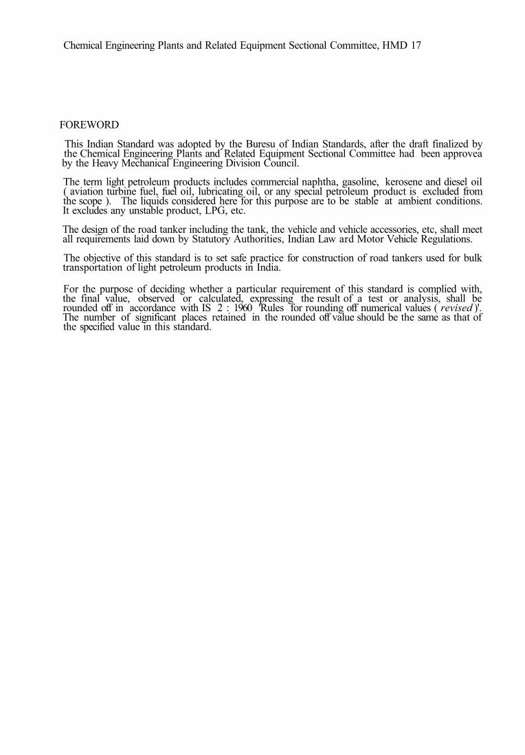
Chemical Engineering Plants and Related Equipment Sectional Committee, HMD 17
FOREWORD
This Indian Standard was adopted by the Buresu of Indian Standards, after the draft finalized by the Chemical Engineering Plants and Related Equipment Sectional Committee had been approvea by the Heavy Mechanical Engineering Division Council.
The term light petroleum products includes commercial naphtha, gasoline, kerosene and diesel oil ( aviation turbine fuel, fuel oil, lubricating oil, or any special petroleum product is excluded from the scope ). The liquids considered here for this purpose are to be stable at ambient conditions. It excludes any unstable product, LPG, etc.
The design of the road tanker including the tank, the vehicle and vehicle accessories, etc, shall meet all requirements laid down by Statutory Authorities, Indian Law ard Motor Vehicle Regulations.
The objective of this standard is to set safe practice for construction of road tankers used for bulk transportation of light petroleum products in India.
For the purpose of deciding whether a particular requirement of this standard is complied with, the final value, observed or calculated, expressing the result of a test or analysis, shall be rounded off in accordance with IS 2 : 1960 'Rules for rounding off numerical values ( revised )'. The number of significant places retained in the rounded off value should be the same as that of the specified value in this standard.
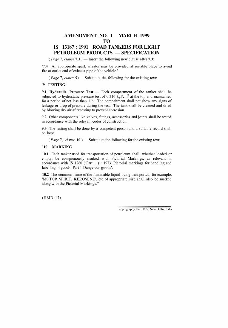
AMENDMENT NO. 1 MARCH 1999 TO
IS 13187 : 1991 ROAD TANKERS FOR LIGHT PETROLEUM PRODUCTS — SPECIFICATION
( Page 7, clause 7.3 ) — Insert the following new clause after 7.3:
'7.4 An appropriate spark arrestor may be provided at suitable place to avoid fire at outlet end of exhaust pipe of the vehicle.'
( Page 7, clause 9) — Substitute the following for the existing text:
'9 TESTING
9.1 Hydraulic Pressure Test — Each compartment of the tanker shall be subjected to hydrostatic pressure test of 0.316 kgf/cm2 at the top and maintained for a period of not less than 1 h. The compaitment shall not show any signs of leakage or drop of pressure during the test. The tank shall be cleaned and dried by blowing dry air after testing to prevent corrosion.
9.2 Other components like valves, fittings, accessories and joints shall be tested in accordance with the relevant codes of construction.
9.3 The testing shall be done by a competent person and a suitable record shall be kept.'
( Page 7, clause 10 ) — Substitute the following for the existing text:
"10 MARKING
10.1 Each tanker used for transportation of petroleum shall, whether loaded or empty, be conspicuously marked with Pictorial Markings, as relevant in accordance with IS 1260 ( Part 1 ) : 1973 'Pictorial markings for handling and labelling of goods: Part 1 Dangerous goods'.
10.2 The common name of the flammable liquid being transported, for example, 'MOTOR SPIRIT, KEROSENE', etc of appropriate size shall also be marked along with the Pictorial Markings."
(HMD 17)
Reprography Unit, BIS, New Delhi, India
IS 13187 : 1991
Indian Standard ROAD TANKERS FOR LIGHT PETROLEUM
PRODUCTS — SPECIFICATION 1 SCOPE
1.1 This standard covers basic requirements for the design, construction, inspection, filling ratio of tankers and design of vehicles and ancillary equipments. 1.2 This specification is meant mainly for tankers for light petroleum products like commercial naphtha, gasoline, kerosene, diesel oil, etc. The products like aviation turbine fuel which require special precautions for purity and heavy pro-ducts, such as lubricating oils, fuel oils, etc, are not covered in this standard. Also, unstable products and LPG are excluded from the scope of this standard.
2 REFERENCES 2.1 The following Indian Standards are neces-sary adjuncts to this standard:
IS No. 226 : 1975
1079 : 1988
1239 (Part 1) : 1979
1367 : 1979
1875 : 1978
1978 : 1982 2004 : 1978
2062 : 1984
2712 : 1979
2825 : 1969
Title Structural steel ( standard quality ) ( fifth revision ) Hot rolled carbon steel sheet and strip ( fourth revision ) Mild steel tubes tubulars and other wrought steel fittings: Part 1 Mild steel tubes ( fourth revision ) Technical supply conditions for threaded steel fasteners ( second revision ) Carbon steel billets, blooms, slabs and bars for forgings ( fourth revision ) Line pipe ( second revision ) Carbon steel forgings for general engineering purposes ( second revision ) Weldable structural steel ( third revision ) Compressed asbestos fibre jointings ( second revision ) Code for unfire pressure vessels
3 TANK DESIGN 3.1 Following design code and regulations in their latest edition are to be followed:
a) Motor Vehicles Regulations of both Central and State Government's of Ope-ration ( RTO );
b) Petroleum Rules for 'Design and Construc-tion of Tank Vehicles for Transporting Petroleum in Bulk';
c) IS 2825 : 1969 for fabrication, welding, inspection and testing; and
d) Any statutory requirements of agencies like CCE, Central Excise, CPWD and SMPV Rules, etc.
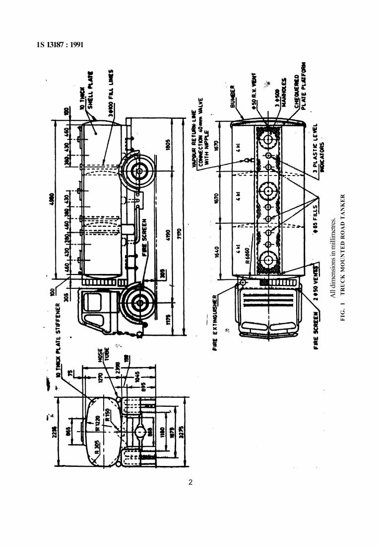
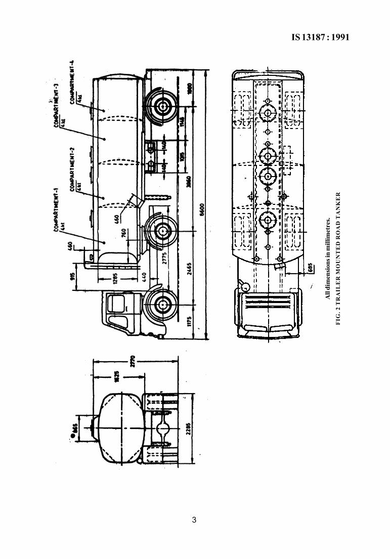
3.2 Tank Capacity 3.2.1 The maximum liquid carrying capacity and dimensions of a road tanker are to be deter-mined by the current Motor Vehicles Regulation and by tank filling criteria outlined in 4 of this specification. Both the requirements shall be satisfied. However, the maximum Liquid Carry-ing Capacity shall not be more than 25 kilolitres (kl) and maximum compartment size shall not be more than 5 kl with oil tight partition. Following tank-truck size could be used as a guide.
Tank-Truck Size 12 kl 16 kl
Compartments 3 × 4 kl each 4 × 4 kl each
NOTE — Figures 1 and 2 provide some guidelines for the design of trucik mounted and trailer mounted road tankers respectively.
3.2.2 The maximum width of any tank and its service equipment/accessories shall be such that it does not project beyond the overall width of the vehicle on which it is mounted or by which it is being towed. The minimum allowable road clearance of any tank component or protection devices located between any two adjacent axles on a vehicle or a vehicle combination shall be at least 12.5 mm for each 300 mm separating such axles and in no case shall this clearance be less than 300 mm.
3.2.3 Materials
The different parts of the tanker shall be made froiai the materials as given in Table 1. 3.2.3.1 Other suitable equivalent materials may be used for the pressure parts as agreed upon by the purchaser, manufacturer and the inspecting authority. All grades of steel used in fabrication shall be of weldable quality.
3.2.4 Thickness of Metal
3.2.4.1 Minimum thickness of tank ends, parti-tions, baffles and stiffeners shall not be less than 2 mm for tanks having volume capacity up to and including 21 litres per centimetre and 2.7 mm for tanks having volume capacity exceeding
1
1S 13187 : 1991
All
dim
ensio
ns in
mill
imetr
es.
FIG
. 1
TR
UC
K M
OU
NT
ED
RO
AD
TA
NK
ER
2
IS 13187 : 1991
All
dim
ensio
ns in
mill
imet
res.
FIG
. 2 T
RA
ILE
R M
OU
NT
ED
RO
AD
TA
NK
ER
3
IS 13187 : 1991
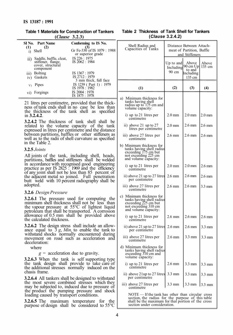
Table 1 Materials for Construction of Tankers (Clause 3.2.3)
SI No. (1)
i)
ii)
iii) iv)
V)
vi)
Part Name (2)
Shell
Saddle, baffle, cleat, stiffener, flange. cover, structural component Bolting Gaskets
Pipes
Forgings
Conforming to IS No. (3)
Gr Fe-330 of IS 1079 : 1988 or superior grade
IS 226 : 1975 IS 2062 : 1984
IS 1367 : 1979 IS 2712 : 1979
3 mm thick, full face IS 1239 ( Part 1) : 1979 IS 1978 : 1982 IS 2004 : 1978 IS 1875 : 1978
21 litres per centimetre, provided that the thick-ness of tank ends shall in no case be less than the thickness of the tank shell as specified in 3.2.4.2. 3.2.4.2 The thickness of tank shell shall be related to the volume capacity of the tank expressed in litres per centimetre and the distance between partitions, baffles or other stiffeners as well as to the radii of shell curvature as specified in the Table 2. 3.2.5 Joints All joints of the tank, including shell, heads, partitions, baffles and stiffeners shall be welded in accordance with recognised good engineering practice as per IS 2825 : 1969 and the efficiency of any joint shall not be less than 85 percent of the adjacent metal so joined. Full penetration butt weld with 10 percent radiography shall be adopted. 3.2.6 Design Pressure 3.2.6.1 The pressure used for computing the minimum shell thickness shall not be less than the vapour pressure at 55°C of lightest liquid petroleum that shall be transported. A corrosion allowance of 0.5 mm shall be provided above the calculated thickness. 3.2.6.2 The design stress shall include an allow-ance equal to 3 g, Min, to enable the tank to withstand shocks normally encountered during movement on road such as acceleration and deceleration:
where g = acceleration due to gravity.
3.2.6.3 When the tank is self supporting type the tank design shall provide to take care of the additional stresses normally induced on the chasis frame. 3.2.6.4 All tankers shall be designed to withstand the most severe combined stresses which they may be subjected to, induced due to pressure of the product the pumping pressure and shock loading caused by transport conditions. 3.2.6.5 The maximum temperature for the purpose of design shall be considered to 55°C
Table 2 Thickness of Tank Shell for Tankers (Clause 3.2.4.2)
Shell Radius and Capacities of Tanks
(1)
a) Minimum thickness for tanks having shell radius up to 175 cm and volume capacity:
i) up to 21 litres per centimetre
ii) above 21 up to 27 litres per centimetre
iii) above 27 litres per centimetre
b) Minimum thickness for tanks having shell radius exceeding 175 cm but not exceeding 225 cm and volume capacity:
i) up to 21 litres per centimetre
ii) above 21 up to 27 litres per centimetre
iii) above 27 litres per centimetre
c) Minimum thickness for tanks having shell radius exceeding 225 cm but not exceeding 310 cm and volume capacity:
i) up to 21 litres per centimetre
ii) above 21 up to 27 litres per centimetre
iii) above 27 litres per centimetre
d) Minimum thickness for tanks having shell radius exceeding 310 cm and volume capacity:
i) up to 21 litres per centimetre
ii) above 21up to 27 litres per centimetre
iii) above 27 litres per centimetre
Distance Between Attach-meat of Partition, Baffle
and Stiffeners
Up to and Including 90 cm
(2)
2.0 mm
2.0 mm
2.6 mm
2.0 mm
2.6 mm
2.6 mm
2.6 mm
2.6 mm
2.6 mm
2.6 mm
3.3 mm
3.3 mm
Above 90 cm Up
to and Including
135 cm
(3)
2.0 mm
2.6 mm
2.6 mm
2.0 mm
2.6 mm
2.6 mm
2.6 mm
2.6 mm
3.3 mm
3.3 mm
3.3 mm
3.3 mm
Above 135 cm
(4)
2.0 mm
2.6 mm
2.6 mm
2.6 mm
2.6 mm
3.3 mm
2.6 mm
3.3 mm
3.3 mm
3.3 mm
3.3 mm
3.3 mm
NOTE — If the tank has other than circular cross section, the radius for the purpose of this table shall be the maximum for that portion of the cross section under consideration.
4
IS 13187 : 1991
( bulk liquid ). Outside solar radiation shall be considered to compute the maximum heat input for design of Pressure relief system. 3.2.6.6 The design of various other components auch as stiffener, partition plates, saddles sup-ports, etc, shall be carried out as per sound cngineering practices. 3.2.6.7 On demand by the purchaser the manufacturer should be able to prove that no component of the vessel is stressed beyond 147 N/mm2 under worst combination of loadings.
3.3 Connecting Points and Manholes 3.3.1 Connecting points shall be constructed as machined or forged pads and provided with studs for flanged fittings. 3.3.2 Threaded connections may be provided with suitably designed pad nozzle with gaskets. 3.3.3 Every compartment shall be fitted with a manhole with flange.
3.4 Anchoring of Tank 3.4.1 The tank shall be securely anchored to the vehicle in a manner that will not:
a) introduce undue concentration of stresses; b) impair the stability and performance of
the vehicle; and c) allow any movement between the tank
and the vehicle due to starting, stopping and turning.
3.4.2 All stops and anchors used to anchor a tank to the vehicle shall be installed so as to be readily accessible for inspection and main-tenance. 4 TANK FILLING CRITERIA 4.1 The maximum quantity of liquid filled in any tank shall be such that the tank is not more than 97 percent full, considering the expansion of the contents with rise in temperature up to the maximum design temperature of the tank.
5 TANKER ACCESSORIES 5.1 Discharge Faucet 5.1.1 Each compartment of tank shall be fitted with a properly designed discharge faucet. The discharge end of the faucet shall be threaded or designed so as to permit the hose being tightly coupled to it.
5.2 Emergency Discharge Control 5.2.1 The outlet of each compartment of the tank shall have an efficient and reliable shut-off valve located inside the shell or in a sum form-ing an integral part of the shell. 5.2.2 The operating mechanism for the shut-off valve shall be provided with a secondary control in an easily accessible position but remote from all fill openings and discharge faucets.
5.2.3 The secondary control as given in 5.2.2 shall be provided with a fusible section which will permit the shut-off valve to close auto-matically in the event of a fire. 5.2.4 A shear section which will break under strain shall be provided between the internal shut-off valve and the discharge faucet. The shear section shall be located as close as possible to the internal shut-off valve.
5.3 Normal Venting 5.3.1 Every compartment of the tank shall be fitted with an inaependent, vacuum and pressure operated vent with an effective opening of 3 cm2 Min, the opening being covered with two layers of non-corroding metal wire gauge having not less than 11 meshes per centimetre. 5.3.2 The vent shall be arranged so as to limit the pressure within the compartment to 0.021 N/mm2 and the vacuum equivalent to 5 centimetre water column. 5.3.3 The vent shall be designed so as to prevent loss of liquid through it, in the event of vehicle-upset.
5.4 Emergency Venting for Fire Exposure 5.4.1 In addition to normal venting, every compartment of the tank shall be fitted with an emergency venting facility which shall be of fusible type so as to provide a minimum fire venting opening having a net area in square centimetres equal to 8 plus 4.3 times the gross capacity of the compartment in kilolitres. 5.4.2 The emergency vent shall be designed so as to prevent loss of liquid through the vent in the case of vehicle upset except in the case of pressure rise during upset position. 5.4.3 Fusible vents shall be actuated by elements which will operate at a temperature not exceeding 93°C.
5.5 Top Filling Pipe 5.5.1 The inner end of the filling pipe shall be fitted with a proper type of splash deflector and the outer end threaded or designed so as to ensure leak-proof connection with the filling hose. 5.5.2 Top filling pipe, if provided, shall be carried down nearly to the bottom of the tank. 5.5.3 The outer end of the filling pipe shall be fitted with an oil-light locker cap.
5.6 Tank Ganging Arrangement 5.6.1 Each compartment shall be fitted with a dip pipe or any other approved tank gauging device. 5.6.2 The dip pipe, if provided, shall be carried up to the bottom of the tank and all openings in the dip pipe, except the capped top openings,
5
IS 13187 : 1991
shall be covered with two layers of wire gauge having not less than 11 meshes per centimetre. 5.6.3 The dip pipe shall be fitted with an oil-tight locker cap.
5.7 Tanker Overturn Protection 5.7.1 All tank top fittings shall be protected from damage in the event of overturning of the vehicle chasis on which it is mounted. 5.7.2 Protection to tank top fittings shall be provided by enclosing them within the contour of the shell or within a rigid covering welded to the tank shell.
6 TRANSPORTATION VEHICLE
6.1 General 6.1.1 The transportation vehicle together with their carrying tankers and equipment must comply with appropriate legislation. 6.1.2 A trailor shall have not less than four wheels. The distance between the centres of the foremost and rearmost wheels on the same side of the trailor shall not be less than 60 percent of its overall length. 6.1.3 Height of any part of vehicle including the tanker and its components shall not exceed 4.1 metres with inflated tyres. 6.1.4 Maximum weight of liquid for which the vehicle is designed shall not exceed the difference between the unladen weight of vehicle and maximum gross weight permitted for that class of vehicle under the appropriate transport regulations. 6.1.5 There shall be a clear space of at least 150 mm between the tank and the back of the cab or fire resisting shield. 6.1.6 The rear of the tank shall be protected with robust steel guards or by the frame of the vehicle, situated at least 75 mm to the rear of the rearmost part of the tank and extended on each side of the vehicle to at least the maximum width of the tank. 6.1.7 As far as possible combustible material shall not be used for making the cabin.
6.2 Design Safety Requirements — Mechanical 6.2.1 The engine of the vehicle shall be of an internal combustion type. 6.2.2 Where the fuel system is gravity-fed type, a quick action cut-off-valve shall be fitted to the fuel feed pipe in an easily accessible and clearly marked position. 6.3 Design Safety Requirements — Electrical 6.3.1 The Metrical system of the vehicle shall have following features:
a) The batteries shall be at an easily accessible position. If plaoed elsewhere
than under the bonnet of the engine, they must be secured in cases having vents and electrically insulated walls.
b) A readily accessible cut-off switch shall be provided of not less than 300 A rating.
c) Wiring so fixed and protected as to minimise accidental damage or undue wear.
d) With the exception of the ignition circuit, the pressure on any circuit shall not exceed 24 volts.
e) All electrical circuits shall be wired independent of the chasis, except starter and ignition high voltage circuits which may use the chasis as the earth return. When an earth return is used, adequate steps shall be taken to ensure electrical continuity and where necessary, compo-nents shall be bonded by copper straps or tapes of adequate capacity and strength. All conductors shall have a wide margin of safety to prevent overheating and shall be adequately insulated.
f) All circuits other than the starter and ignition high voltage circuits, charging circuits and solenoid operated stop con-trols shall be protected against overload-ing by fuses or automatic cut-outs. The wiring shall be firmly attached and so placed that the conductors are protected against jolting, stones thrown up and heat from the exhaust.
g) Electrical conductors behind drivers's cab must consist of cables protected by flexible seamless and rust proof casings.
h) The whole electrical equipment shall be designed, installed and protected in such a way so as not to cause any fire or short circuit in the normal conditions of use of the vehicle and so as to reduce the risk of either occurrence in the event of equip-ment being jolted or strained to a minimum.
j) Screw-in bulbs shall not be used except in safe areas classified by statutory code.
k) The tanker including its service equip-ment shall be electrically bonded to the vehicle and the vehicle shall be properly earthed.
m) The transport vehicle shall be fitted with direction indicators showing a flashing amber light and otherwise complying with the requirements of road vehicle lighting regulations. An emergency warning flashing device which may be operated so as to cause all the the direction indicators on the vehicle and its trailor to flash simultaneously on both sides shall be provided.
6
IS 13187 : 1991
n) The engine and exhaust system together with all electrical generator, motors, batteries, switch gears, fuses, etc, of a motor vehicle shall be effectively screened from the tank. A fire resisting shield shall be provided between the cab and the tank or the above shall be housed in an approved fire resisting compartment.
6.4 Tool Kit/Accessories 6.4.1 Every truck shall be provided with tools and accessories sufficient in number and sizes to take care of on the spot minor jobs.
6.5 First-Aid Kit 6.5.1 A first-aid box shall be provided in each truck and kept in an easily accessible place in the truck.
7 FIRE PROTECTION 7.1 One serviceable fire extinguisher of dry chemical type of 9 to 10 kg capacity shall be provided on each side of the vehicle, which shall be accessible from outside the cab. The seal, nozzle dust cap and the trigger mechanism of the extinguisher should be checked daily. The weight of the CO2 cartridge, condition of the powder, cover gasket and hose pipe should be checked every month. The clamps on the bracket provided for the fire extinguisher, should allow for their easy removal and putting back. Alter-natively any latest more effective fire extinguisher of equivalent capacity (using inert gas like halon, etc) may also be used subject to agree-ment between the purchaser and the supplier and approved by Inspection Authority.
7.2 A person while inside or attending any vehicle conveying flammable oil shall not smoke or use matches or lighters.
7.3 No fire, artificial light or article capable of causing fire or explosion shall be taken or carried on any vehicle carrying flammable oil.
8 INSPECTION 8.1 Manufacturer of the tanker shall furnish detail of manufacturing facilities, design cap-ability, past experience in executing similar jobs, etc.
8.2 Tank shall be inspected during manufacture, additions/alterations or repair on the equipment.
9 TESTING 9.1 The tanker and all its components like valve, fitting, accessories and joints shall be tested in accordance with the relevant code of construc-tion. The tank shall be cleaned and dried by blowing dry air after testing to prevent corrosion. 9.2 The testing shall be done by a competent person and a suitable record shall be kept.
10 MARKING 10.1 Each tanker used for transportation of petroleum shall, whether loaded or empty, be conspicuously marked on each side and rear thereof in letters at least 7 cm high on a back-ground of sharply contrasting colour the word 'FLAMMABLE' and the common name of the flammable liquid being transported, for example, 'MOTOR SPIRIT', 'KEROSENE', etc.
11 EXTERNAL PAINTING 11.1 Tanker shall be adequately painted exter-nally to prevent corrosion arising from atmospheric influence. Painting shall be carried out as per following:
a) Surface Preparation This shall be done with the help of blast cleanins.
b) Primer Epoxy zinc chromate primer 2 coats. Dry Film Thickness, 35 microns/coat, Min.
c) Finish Coat Acrylic polyurethane paint 2 coats. Dry film thickness, 30 to 40 microns/coat, Min.
12 CERTIFICATION 12.1 A certificate shall be issued for each tanker after inspection and testing by the inspecting authority. The initial certificate will remain valid for 5 years and subsequently revalidation of certificate should be obtained from inspection/ competent authority once in 2 years.
7
Standard Mark
The use of the Standard Mark is governed by the provisions of the Bureau of Indian Standards Act, 1986 and the Rules and Regulations made thereunder. The Standard Mark on products covered by an Indian Standard conveys the assurance that they have been produced to comply with the requirements of that standard under a well defined system of inspection, testing and quality control which is devised and supervised by BIS and operated by the pro-ducer. Standard marked products are also continuously checked by BIS for conformity to that standard as a further safeguard. Details of conditions under which a licence for the use of the Standard Mark may be granted to manufacturers or producers may be obtained from the Bureau of Indian Standards.
Bureau of Indian Standards
BIS is a statutory institution established under the Bureau of Indian Standards Act, 1986 to promote harmonious development of the activities of standardization, marking and quality certification of goods and attending to connected matters in the country.
Copyright
BIS has the copyright of all its publications. No part of these publications may be reproduced in any form without the prior permission in writing of BIS. This does not preclude the free use, in the course of implementing the standard, of necessary details, such as symbols and sizes, type or grade designations. Enquiries relating to copyright be addressed to the Director ( Publication ), BIS.
Revision of Indian Standards
Indian Standards are reviewed periodically and revised, when necessary and amendments, if any, are issued from time to time. Users of Indian Standards should ascertain that they are in possession of the latest amendments or edition. Comments on this Indian Standard may be sent to BIS giving the following reference :
Doc : No. HMD 17 (4765)
Amendments Issued Since Publication
Amend No. Date of Issue Text Affected
BUREAU OF INDIAN STANDARDS
Headquarters :
Manak Bhavan, 9 Bahadur Shah Zafar Marg, New Delhi 110002 Telephones : 331 01 31, 331 13 75 Telegrams : Manaksanstha
( Common to all Offices )
Regional Offices :
Central : Manak Bhavan, 9 Bahadur Shah Zafar Marg NEW DELHI 110002
Eastern : 1/14 C.I.T. Scheme VII M, V.I.P. Road, Maniktola CALCUTTA 700054
Northern : SCO 445-446, Sector 35-C, CHANDIGARH 160036
Southern : C.I.T. Campus, IV Cross Road, MADRAS 600113
Western : Manakalaya, E9 MIDC, Marol, Andheri ( East ) BOMBAY 400093
Telephone
331 01 31 331 13 75
37 86 62
53 38 43
2350216
6 32 92 95
Branches : AHMADABAD. BANGALORE. BHOPAL. BHUBANESHWAR. COIMBATORE. FARIDABAD. GHAZIABAD. GUWAHATI. HYDERABAD. JAIPUR. KANPUR. PATNA. THIRUVANANTHAPURAM.
Printed at Swatantra Bharat Press, Delhi, India