Embed Size (px)
Citation preview
Disclosure to Promote the Right To Information
Whereas the Parliament of India has set out to provide a practical regime of right to information for citizens to secure access to information under the control of public authorities, in order to promote transparency and accountability in the working of every public authority, and whereas the attached publication of the Bureau of Indian Standards is of particular interest to the public, particularly disadvantaged communities and those engaged in the pursuit of education and knowledge, the attached public safety standard is made available to promote the timely dissemination of this information in an accurate manner to the public.
इंटरनेट मानक
“!ान $ एक न' भारत का +नम-ण”Satyanarayan Gangaram Pitroda
“Invent a New India Using Knowledge”
“प0रा1 को छोड न' 5 तरफ”Jawaharlal Nehru
“Step Out From the Old to the New”
“जान1 का अ+धकार, जी1 का अ+धकार”Mazdoor Kisan Shakti Sangathan
“The Right to Information, The Right to Live”
“!ान एक ऐसा खजाना > जो कभी च0राया नहB जा सकता है”Bhartṛhari—Nītiśatakam
“Knowledge is such a treasure which cannot be stolen”
“Invent a New India Using Knowledge”
है”ह”ह
IS 12442 (1988): Seamless and welded titanium and titaniumalloy tubes for condensers and heat exchangers [MTD 7:Light Metals and their Alloys]

8 n
UDC 621’643’2 : 669’295-462’3 : 621 ‘I 75 - . _.. . . . . . l *.
Indian Standard
SPECIFICATION FOR SEAMLESS AND WELDED TITANIUM AND TITANIUM
ALLOY TUBES FOR CONDENSERS AND HEAT EXCHANGERS
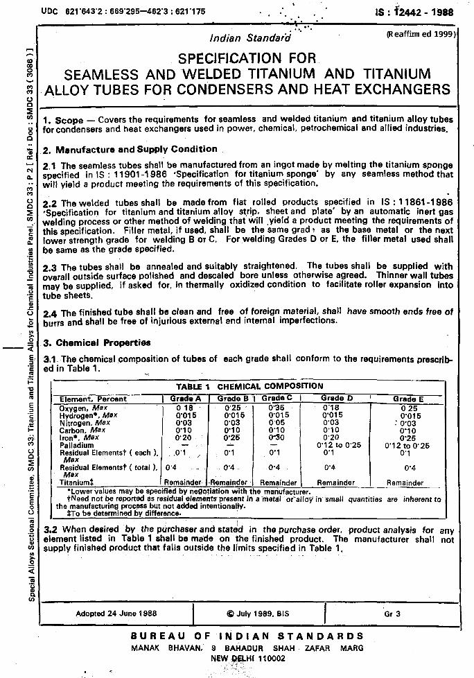
1. scope - Covers the requirements for seamless and welded titanium and titanium alloy tubes for condensers and heat exchangers used in power, chemical, petrochemical and allied industries,
3. Manufacture and Supply Condition
2.1 The seamless tubes shall be manufactured from an ingot made by melting the titanium sponge specified in IS : 11901-l 986 ‘Specification for titanium sponge’ by any seamless method that will yield a product meeting the requirements of this specification.
2.3 The welded tubes shall be made from flat rolled products specified in IS : 1 1861-1986 *Specification for titanium and titanium alloy strip. sheet and plate’ by an automatic inert gas welding process or other method of welding that will ,yield a product meeting the requirements of this specification. Filler metal, if used, shall be the same grad? as the base metal or the next lower strength grade for welding B or C. For welding Grades D or E, the filler metal used shall be same as the grade specified.
3.3 The tubes shall be annealed and suitably straightened. The tubes shall be supplied with overall outside surface polished and descaled bore unless otherwise agreed. Thinner wall tubes may be supplied, if asked for, in thermally oxidized condition to facilitate roller expansion into tube sheets.
3.4 The finished tube shall be clean and free of foreign. material, shall have smooth ends free of burrs and shall be free of injurious external and internal ItnperfeCtiOnS.
3. Chemical Properties
3.1 The chemical composition of tubes of each grade shall conform to the requirements prescrib- ed in Table 1. ”
TABLE 1 CHEMICAL COMPOSITION
Element. Percent 1 Grade A Grade B I Grade C I Grade D I Grade E Oxygen, Max 016 ’ 0’25 0’35 ’ 078 0 25 Hydrogen.. Max 0’015 0’015 Nitrogen. Max
TOI 5 0’03
“0:;;” gd”ol35 : 0’03
Carbon, Max % . 0’10 0’10 0’10 0’10 Iron+, Max 0’20 0’25 030 0’20 0’25 Palladium - - 0’12 to 0’25 0’12 to 0’ 25 Fle&ual Elementst ( each ). .O’I ,, 07 0’1 0’1 0’1
R;;tral Elementst ( total ), 0’4 - 0’4
I
0’4 0’4 0’4
Titaniumt Remainder Remainder Remainder Remainder Remainder ‘Lower values may be specified by negotiation with the manufacturer. tNeed not be reported as residual elements present in ametal oralloy^ in- small quantities are inherent to
the manufacturing process but not added intentionally. *To be determined by difference.
3.2 When desired by the purchaser and stated in the purchase order, product analysis for any element listed in Table 1 shall be made on the finished product. The manufacturer shall not supply finished product that falls outside the limits specified in Table 1,
. _ I
Adopted 24 June 1988 I
0 July 1989, BIS I
Gr 3
BUREAU OF INDIAN STANDARDS MANAK BHAVAN, 9 BAHADUR SHAH ZAFAR MARG
NEw 163fLHl 110002 . . :, I1
. . . ; sL /
:.
i
IS : 12442 - 1988
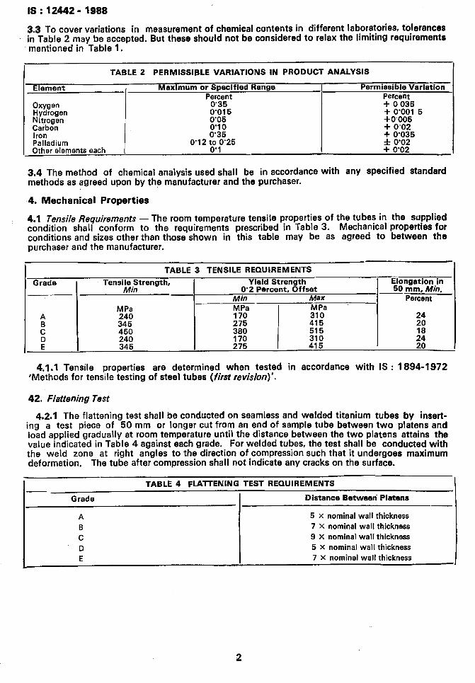
3.3 To cover variations in measurement of chemical contents in different laboratories, tolertinces ’ in Table 2 may be accepted. But these should not be considered to relax the limiting requirements
mentioned in Table 1.
I TABLE 2 PERMISSIBLE VARIATIONS IN PRODUCT ANALYSIS
I I
Element , Maximum or Specified Range I Permissible Variation Percent Percent I
0’35 0’015 0’05 0’10 0’35
+ 0035 I Oxygen Hydrogen + 0’001 5 Nitrogen +0.005 I Caibon + 0’02 Iron + 0’035 I Palladium Other elements each I 0’12 6” p’25
f 0’02 . I + 0’02 I 1
3.4 The method of chemical analysis used shall be in accordance with any specified standard methods as agreed upon by the manufacturer and the purchaser.
4. Mechanical Properties
4.1 Tensile Requirements - The room temperature tensile properties of the tubes in the supplied condition shall conform to the requirements prescribed in Table 3. Mechanical properties for conditions and sizes other than those shown in this table may be as agreed to between the purchaser and the manufacturer.
I TABLE 3 TENSILE REQUIREMENTS I Grade
A
:
D E
Tensigitrength,
MPa 240
345 450
240 345
Yield Strength O-2 Percent, Offset
Min Max
MPa MPa 170 310
275 380 415 515
170 310 275 415
19;nz;io;in .
Perc’ent
24
20 18
:;:
4.1.1 Tensile properties are determined when tested in accordance with IS : 1894-1972 ‘Methods for tensile testing of steel tubes (first revision)‘.
42. Flattening Test
4.2.1 The flattening test shall be conducted on seamless and welded titanium tubes by insert- ing a test piece of 50 mm or longer cut from an end of sample tube between two platens and load applied gradually at room temperature until the distance between the two platens attains the value indicated in Table 4 against each grade. For welded tubes, the test shall be conducted with the weld zone at right angles to the direction of compression such that it undergoes maximum deformation. The tube after compression shall not indicate any cracks on the surface.
TABLE 4 FLATTENING TEST REQUIREMENTS
Grade Distance Between Platens
A 5 X nominal wall thickness
B 7 x nominal wall thickness
C 9 x nominal wall thickness D 5 X nominal wall thickness
E 7 X nominal wall thickness
2
IS: 12442- 1988
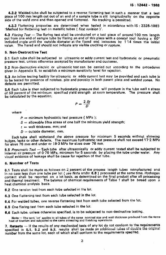
4.2.2 Welded tube shall be subjected to a reverse flattening test in such a manner that a test piece of 100 mm length cut out of an end of a sample tube is slit longitudinally on the opposite side of the weld zone and then opened and flattened. No cracking is permitted.
4.2.3 Flattening properties are determined when tested in accordance with IS : 2328-1983 ‘Method for flattening test cn metallic tubes ( first revision )‘.
4.3 Flaring Test - The flaring test shall be conducted on a test piece of around 100 mm length cut from one end of sample tube by flaring an end of this piece with a conical tool having a 60” included angle until the outside diameter at the flared end increases by 1’14 times the initial value. The flared end should not indicate any visible cracking or rupture.
5. Non-Destructive Test
5.1 Each tube shall be subjected to ultrasonic or eddy current test and hydrostatic or pneumatic pressure test, unless otherwise accepted by manufacturer and customer.
5.2 Non-destructive electric or ultrasonic test can be carried out according to the procedures given in Appendix B, to establish a minimum sensitivity level for rejection.
5.3 An inline testing facility for ultrasonic or eddy current test may be provided and each tube is to be tested for presence of notches, pits and porosity in both parent plate and welded zones. No defects are permitted.
5.4 Each tube is then subjected to hydrostatic pressure that will produce in the tube wall a stress of 50 percent of the minimum specified yield strength at room temperature. The pressure shall be calculated by the equation:
pc2st D
where
P a minimum hydrostatic test pressure ( MPa );
S = allowable fibre stress of one half the minimum yield strength;
t I wall thickness, mm; and
D = outside diameter, mm.
Each tube shall withstand the above pressure for minimum 5 seconds without showing bulges, leaks or other defects. The maximum hydrostatic test pressure shall not exceed 17.2 MPa for sizes 76 mm and under or 19.3 MPa for sizes over 76 mm,
5.5 Pneumatic Test - Each tube after ultrasonically or eddy current tested shall be subjected to internal air pressure of 0.70 MPa, minimum for 5 seconds by placing the tube under water. Any visual evidence of leakage shall be cause for rejection of that tube.
6. Number of Tests
5.1 Tests shali be made as follows on 2,percent of the process iength tubes manufactured and in no case less than one tube per lot ( see Note under 6.6 ) processed at the same time. Hydrogen content shall be reported on a lot basis, as determined on the final product after all processing and thermal treatment. The balance of chemical requirements of Table 1 shall be based upon a heat chemical analysis basis.
6.2
6.3
6.4
6.5
6.6
One tension test from each tube selected in the lot.
One flattening test from each tube seiected in the iot.
For welded tubes, one reverse flattening test from each tube selected from the lot.
One flaring,test from each tube selected in the lot.
Each tube, unless otherwise specified, is to be subjected to non-destructive testing.
Note - The term ‘lot’ applies to all tubes of the same nominal size and wall thickness produced from the same _. . . . _. heat of titanium and subjected to the same annealing and tn-usnmg operarlons.
7. Retests - If the results of any mechanical tests of any lot do not conform to the requirements - - ^ r.:“:..-, specified in 5.1, 5.2 and 5.3, resuits shaii be made on additionai tubes of double tht: U~I~~I~WII number from the same lot, each of which shall conform to the requirements specifed.
3
IS : 12442 - 1988
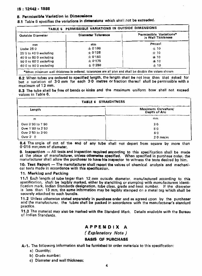
8. permissible Variation in Dinaenshs 8.1 Table 5 specifies the variations in dhnensians which &all not be exceeded-
TABLE 5 PEPMlSSlSLE VARIATIONS IN OUTStDE UtMENStONS
Outside Diameter Diameter Tolerance Permissible Variations* in Wall Thickness
mm
Under 25’0
25’0 to 40’0 excluding
40’0 to 50‘0 excluding 50’0 to 60’0 excluding
60’0 to 90’0 excluding
mm
f 0’100
f 0’125
f 0’150
f 0’175
f 0.250
Percent
f IO
f 10
f10
f 10
f 10
*When minimum wall thickness is ordered, tolerances are all plus and shall be double the values shown.
8.2 When tubes are ordered to specified length, the length shall be not less than that asked for but a variation of 3.0 mm for each 30 metres Or fraction thereof shall be permissible with a maximum of 13 mm. 9.3 The tube shall be,free of bends or kinks and the, maximum uniform bow shall not exceed values in Table 6.
TABLE 6 STRAIGHTNESS
Length Maximum Curvature/ Depth of Arc
m mm
Over 0’90 to 1‘80 3’0
Over 1’80 to 2’50 5.0 Over 2’50 to 3’00 6.0 Over 3’ 0 2’0 mm/m
8.4 The angle of cut of the end of any tube shall not depart from square by more than O-01 6 mm/mm of diameter,
9. Inspection - All tests and inspection required according to this specification shall be made at the place of manufacturer, unless: otherwise specified. When specified in purchase order, the manufacturer shall allow the purchaser to- heve:his-inspector to witness the tests desired by him.
10. Test Report - The manufacturer shall report the values of chemical analysis and mechani- cal tests made in accordance with this specification.
11. Marking and Packing
11.1 Each length of tube larger than 12 mm outside diameter, manufactured according to this specification, shall be legibly marked, either by stencilling or stamping with manufacturers identi- fication mark, Indian Standards designation, tube class, grade and heat number. If the diameter is less than 13 mm, the same information may be legibly stamped on a metal tag which shall be securely attached to each bundle.
11.2 Unless otherwise stated separately in purohase order and as agreed upon by the purchaser and the manufacturer, the tubes shall be packed in accordance with the manufacturer’s standard practice.
11.3 The material may also be marked with tlie Standard Mark. Details available with the Bureau of Indian Standards,
APPEN.DIX A
(Explanatory Note )
BASJS OF PURCHASE
A-l. The following information shall be furnished to order materials to this specification:
a) Quantity;
b) Grade number;
c) Diameter and wall thickness;
4
IS : 12442 -1988
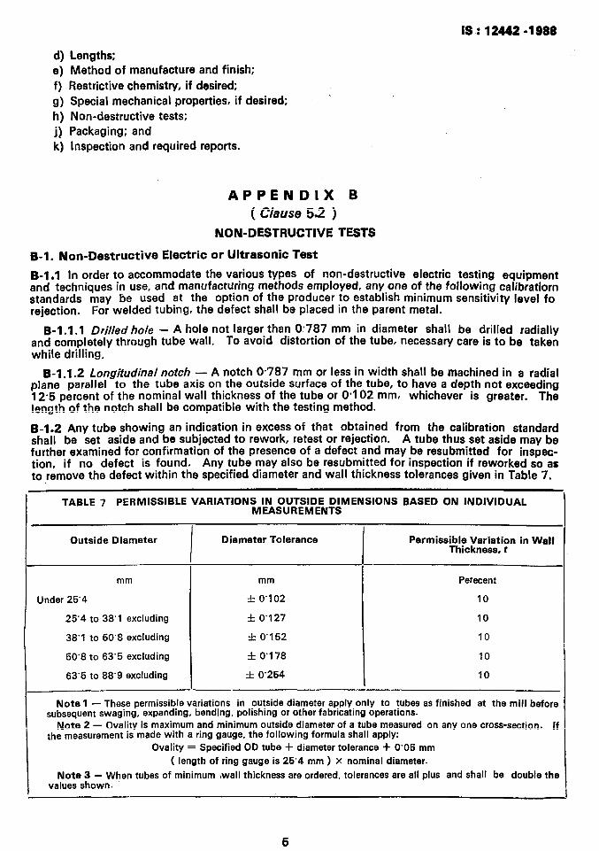
d) e) f) 9) h) i) W
Lengths: Method of manufacture and finish;
Restrictive chemistry, if desired;
Special mechanical properties, if desired;
Non-destructive tests;
Packaging; and
Inspection and required reports.
APPENDIX B . -_. ( clause 5.2 j
NON-DESTRUCTIVE TESTS
S-1. Non-Dastructiva Electric or Ultrasonic Test
B-l.1 In order to accommodate the various types of non-destructive electric testing equipment and techniques in use, and manufacturing methods employed, any one of the following calibratiorn standards may be used at the option of the producer to establish minimum sensitivity level fo rejection. For welded tubing, the defect shall be placed in the parent metal.
B-1.1.1 Drilled hole - A hole not larger than O-787 mm in diameter shall be drilled radially and completely through tube wall. To avoid distortion of the tube, necessary care is to be taken while drilling.
B-1 .1.2 Longitudinal notch - A notch O-787 mm or less in width shall be machined in a radial plane parallel to the tube axis on the outside surface of the tube, to have a depth not exceeding 1 Z-5 percent of the nominal wall thickness of the tube or O-102 mm, whichever is greater. The lnnath Df the notch shall be compatible with the testing method. ._.. J-..
B-1.2 Any tube showing an indication in excess of that obtained from the calibration standard shall be set aside and be subjected to rework, retest or rejection. A tube thus set aside may be further examined for confirmation of the presence of a defect and may be resubmitted for inspec- tion, if no defect is found. Any tube may also be resubmitted for inspection if reworked so as to remove the defect within the specified diameter and wall thickness tolerances given in Table 7.
TABLE 7 PERMISSIBLE VARIATIONS IN OUTSIDE DIMENSIONS BASED ON INDIVIDUAL MEASUREMENTS
Outside Diameter
I
Diameter Tolerance
I
Permissible Variation in Wall Thickness, t
-
mm mm Perecent
Under 25’4 f 0’102 10
25’4 to 38’1 excluding f 0’127 10
38’1 to 50’8 excluding f 0’152 10
50’8 to 63’5 excluding f 0’178 10
63’5 to 88’9 excluding f 0’254 10
Note 1 - These permissible variations in outside diameter apply only to tubes as finished at the mill before subsequent swaging, expanding, bending, polishing or other fabricating operations.
Note 2 - Dvality is maximum and minimum outside diameter of a tube measured on any one cross-section. !f the measurement is made with a ring gauge, the following formula shall apply:
Ovality = Specified OD tube -I- diameter tolerance + 0’05 mm ( length of ring gauge is 25’4 mm ) X nominal diameter.
Note 3 - When tubes of minimum ,wall thickness are ordered, tolerances are all plus and shall be double the values shown.
,
1, ,_, 1. “‘r .:,, I,, ‘; ._
‘_ Ie: 12442 - 1988
EXPLANATORY NOTE
Titanium and its alloys possess high specific strength and excellent corrosion resistance, and are being increasingly used in many chemical, aerospace and other industrial applications. This standard has been prepared as a guide for the consumers of titanium seamless and welded tube for selection of an optimum grade of material required for intended application.
For the benefit of the purchaser, particulars to be specified while ordering for the titanium alloy. tube, etc, have been included in Appendix A. In the preparation of this standard, necessary assistance has been derived from ASTM B-338-1983 Seamless welded titanium and titanium alloy tubes for condensers and heat exchangers, Issued by the American Society for Testing and Materials, USA,
8
Printed .at Printoeraph. New Delhi. India