Embed Size (px)
Citation preview

This document contains proprietary and confidential information which is the property of National Oilwell Varco, L.P., its affiliates or subsidiaries (all collectively referred to hereinafter as "NOV"). It is loaned for limited purposes only and remains the property of NOV. Reproduction, in whole or in part, or use of this design or distribution of this information to others is not permitted without the express written consent of NOV. This document is to be returned to NOV upon request or upon completion of the use for which it was loaned. This document and the information contained and represented herein is the copyrighted property of NOV. © National Oilwell Varco
CURRENT INITIAL
DRAWN J.Kellstrom
TITLE Owner’s Manual
IR3080 Iron Roughneck, 88” Arm Auto-Rotation
CHECKED B.Dominguez
APPVD K. SchmidtSIZE
ADWG NO
D811000104-MAN-001REV
01DATE 2/13/07 SCALE 1/1 WT LBS N/A SHEET 1 OF 1 DCF0045 (REV B)
Bill of Material
Item Quantity Part Number Description
1 1 D811000084-MAN-001 User Manual, Iron Roughneck 2 1 D811000104-DOS-001 Technical Drawing Package 3 1 D811000104-SPL-001 Recommended Spare Parts List
NEXT ASSY PRODUCT 1100012 IR3080

www.nov.comD811001123-GEN-001/02
User Manual
IR3080 & IR30120
with 55"& 88" Arm Assembly
Customer - Rig Name Variable
Reference Reference Description
With 55" and 88" Arm AsemblyThis document contains proprietary and confidential information which is the property of National Oilwell Varco, L.P., its affiliates or subsidiaries (all collectively referred to hereinafter as "NOV"). It is loaned for limited purposes only and remains the property of NOV. Reproduction, in whole or in part, or use of this design or distribution of this information to others is not permitted without the express written consent of NOV. This document is to be returned to NOV upon request or upon completion of the use for which it was loaned. This document and the information contained and represented herein is the copyrighted property of NOV.© National Oilwell Varco
National Oilwell VarcoRIG SOLUTIONS11000 Corporate Centre DriveHouston, TX 77041
Document Number Rev.
D811000084-MAN-001 03

D811000084-MAN-001Revision 03
www.nov.com
Revision History
03 06.17.2009Corrections to Chapter 3. Added graphic to
cover section and bookmarks to pdf fileC. Rodriguez E. Axelson J. Walker
02 04.12.2008 Added missing information, notes and a view T. Rodriguez E. Axelson J. Walker
01 12.03.2007 Create 1 Manual for All IR3080 & IR30120 K Staten B. Winter K Schmidt
Rev Date (dd.mm.yyyy)
Reason for issue Prepared Checked Approved
Change Description
Revision Change Description
03Added information and corrected a note on hazardous area classification for installation in Chapter 3. Added graphic on cover page. Added bookmarks to pdf file.
02Added view with intensifier valve in chapter 2, wrench operational parameters for IR30120. Added notes on chapter 4 on torque values for intensifier valves during makeup and breakout operations.
01 First Issue

Table of Contents
D811000084-MAN-001Revision 03Page i of iv
www.nov.com
Chapter 1: General InformationConventions . . . . . . . . . . . . . . . . . . . . . . . . . . . . . . . . . . . . . . . . . . . . . . . . . . . . . . 1-1
Notes, Cautions, and Warnings . . . . . . . . . . . . . . . . . . . . . . . . . . . . . . . . . . . . . . 1-1Illustrations . . . . . . . . . . . . . . . . . . . . . . . . . . . . . . . . . . . . . . . . . . . . . . . . . . . . . . 1-2
Safety Requirements . . . . . . . . . . . . . . . . . . . . . . . . . . . . . . . . . . . . . . . . . . . . . . 1-3Personnel Training . . . . . . . . . . . . . . . . . . . . . . . . . . . . . . . . . . . . . . . . . . . . . . . . 1-3Recommended Tools . . . . . . . . . . . . . . . . . . . . . . . . . . . . . . . . . . . . . . . . . . . . . . 1-3General System Safety Practices . . . . . . . . . . . . . . . . . . . . . . . . . . . . . . . . . . . . . 1-4Replacing Components . . . . . . . . . . . . . . . . . . . . . . . . . . . . . . . . . . . . . . . . . . . . 1-4Routine Maintenance . . . . . . . . . . . . . . . . . . . . . . . . . . . . . . . . . . . . . . . . . . . . . . 1-4Proper Use of Equipment . . . . . . . . . . . . . . . . . . . . . . . . . . . . . . . . . . . . . . . . . . . 1-4
Chapter 2: DescriptionGeneral Description . . . . . . . . . . . . . . . . . . . . . . . . . . . . . . . . . . . . . . . . . . . . . . . 2-1Wrench Assembly Description . . . . . . . . . . . . . . . . . . . . . . . . . . . . . . . . . . . . . 2-4Spinner Assembly Description . . . . . . . . . . . . . . . . . . . . . . . . . . . . . . . . . . . . . 2-8
Spinner Assembly . . . . . . . . . . . . . . . . . . . . . . . . . . . . . . . . . . . . . . . . . . . . . . . . 2-8Spinner Support Assembly . . . . . . . . . . . . . . . . . . . . . . . . . . . . . . . . . . . . . . . . . . 2-8
Column-Guide-Arm Assembly . . . . . . . . . . . . . . . . . . . . . . . . . . . . . . . . . . . . . 2-10Description . . . . . . . . . . . . . . . . . . . . . . . . . . . . . . . . . . . . . . . . . . . . . . . . . . . . . 2-10General Arrangement . . . . . . . . . . . . . . . . . . . . . . . . . . . . . . . . . . . . . . . . . . . . . 2-10Major Component Description . . . . . . . . . . . . . . . . . . . . . . . . . . . . . . . . . . . . . . 2-13
Column Assembly . . . . . . . . . . . . . . . . . . . . . . . . . . . . . . . . . . . . . . . . . . . . . 2-13Rotate Column Assembly . . . . . . . . . . . . . . . . . . . . . . . . . . . . . . . . . . . . . . . 2-13Arm Assembly . . . . . . . . . . . . . . . . . . . . . . . . . . . . . . . . . . . . . . . . . . . . . . . 2-15Guide Assembly . . . . . . . . . . . . . . . . . . . . . . . . . . . . . . . . . . . . . . . . . . . . . . 2-16
Hydraulic Circuit Components . . . . . . . . . . . . . . . . . . . . . . . . . . . . . . . . . . . . . . 2-17Inline Hydraulic High-Pressure Filter . . . . . . . . . . . . . . . . . . . . . . . . . . . . . . 2-17Wrench Lift Cylinder . . . . . . . . . . . . . . . . . . . . . . . . . . . . . . . . . . . . . . . . . . . 2-17Wrench Lift Manifold Assembly . . . . . . . . . . . . . . . . . . . . . . . . . . . . . . . . . . 2-17Move In-Out Cylinders . . . . . . . . . . . . . . . . . . . . . . . . . . . . . . . . . . . . . . . . . 2-17Move In-Out Manifold Assembly . . . . . . . . . . . . . . . . . . . . . . . . . . . . . . . . . . 2-17Rotation Manifold Assembly . . . . . . . . . . . . . . . . . . . . . . . . . . . . . . . . . . . . . 2-18
IR3080 with 88" Arm Assembly . . . . . . . . . . . . . . . . . . . . . . . . . . . . . . . . . . . 2-19Automated Arm Assembly . . . . . . . . . . . . . . . . . . . . . . . . . . . . . . . . . . . . . . . . . 2-19Automated Arm Assembly . . . . . . . . . . . . . . . . . . . . . . . . . . . . . . . . . . . . . . . . . 2-20Link Assembly . . . . . . . . . . . . . . . . . . . . . . . . . . . . . . . . . . . . . . . . . . . . . . . . . . 2-21
Link Assembly with Tilting Feature . . . . . . . . . . . . . . . . . . . . . . . . . . . . . . . . 2-22Guide Assembly . . . . . . . . . . . . . . . . . . . . . . . . . . . . . . . . . . . . . . . . . . . . . . . . . 2-23Vertical Track Assembly . . . . . . . . . . . . . . . . . . . . . . . . . . . . . . . . . . . . . . . . . . . 2-24Automated Arm Hydraulic Circuit Components . . . . . . . . . . . . . . . . . . . . . . . . . 2-25Automated Arm Hydraulic Circuit Components . . . . . . . . . . . . . . . . . . . . . . . . . 2-26
Inline Hydraulic High-Pressure Filter . . . . . . . . . . . . . . . . . . . . . . . . . . . . . . 2-26Lift Cylinder . . . . . . . . . . . . . . . . . . . . . . . . . . . . . . . . . . . . . . . . . . . . . . . . . . 2-26Lift Cylinder Cross Port Relief Valve (if equipped) . . . . . . . . . . . . . . . . . . . . 2-26Linkage Cylinders . . . . . . . . . . . . . . . . . . . . . . . . . . . . . . . . . . . . . . . . . . . . . 2-26Move In-Out Cylinders and Manifold Valve (if equipped) . . . . . . . . . . . . . . . 2-26
i

Table of Contents
D811000084-MAN-001Revision 03Page ii of iv
Remote Control Console Description . . . . . . . . . . . . . . . . . . . . . . . . . . . . . . . . 2-27Technical Specifications . . . . . . . . . . . . . . . . . . . . . . . . . . . . . . . . . . . . . . . . 2-29
Iron Roughneck Technical Specifications . . . . . . . . . . . . . . . . . . . . . . . . . . . . . 2-29IR3080 with 55" Arm . . . . . . . . . . . . . . . . . . . . . . . . . . . . . . . . . . . . . . . . . . . . . 2-30
General Specifications . . . . . . . . . . . . . . . . . . . . . . . . . . . . . . . . . . . . . . . . 2-30Utility Requirements . . . . . . . . . . . . . . . . . . . . . . . . . . . . . . . . . . . . . . . . . . 2-30IR3080 / 55" Size Specifications . . . . . . . . . . . . . . . . . . . . . . . . . . . . . . . . . 2-31IR3080 / 55" Size Specifications . . . . . . . . . . . . . . . . . . . . . . . . . . . . . . . . . 2-32IR3080 / 55" Size Specifications . . . . . . . . . . . . . . . . . . . . . . . . . . . . . . . . . 2-33IR3080 / 55" Size Specifications . . . . . . . . . . . . . . . . . . . . . . . . . . . . . . . . . 2-34
IR3080 with 88" Arm . . . . . . . . . . . . . . . . . . . . . . . . . . . . . . . . . . . . . . . . . . . . . 2-35General Specifications . . . . . . . . . . . . . . . . . . . . . . . . . . . . . . . . . . . . . . . . 2-35Utility Requirements . . . . . . . . . . . . . . . . . . . . . . . . . . . . . . . . . . . . . . . . . . 2-35IR3080 / 88" Size Specifications . . . . . . . . . . . . . . . . . . . . . . . . . . . . . . . . . 2-36IR3080 / 88" Size Specifications . . . . . . . . . . . . . . . . . . . . . . . . . . . . . . . . . 2-37IR3080 / 88" Size Specifications . . . . . . . . . . . . . . . . . . . . . . . . . . . . . . . . . 2-38IR3080 / 88" Size Specifications . . . . . . . . . . . . . . . . . . . . . . . . . . . . . . . . . 2-39
IR30120 with 55" Arm . . . . . . . . . . . . . . . . . . . . . . . . . . . . . . . . . . . . . . . . . . . . 2-40General Specifications . . . . . . . . . . . . . . . . . . . . . . . . . . . . . . . . . . . . . . . . 2-40Utility Requirements . . . . . . . . . . . . . . . . . . . . . . . . . . . . . . . . . . . . . . . . . . 2-40IR30120 / 55" Size Specifications . . . . . . . . . . . . . . . . . . . . . . . . . . . . . . . . 2-41IR30120 / 55" Size Specifications . . . . . . . . . . . . . . . . . . . . . . . . . . . . . . . . 2-42IR30120 / 55" Size Specifications . . . . . . . . . . . . . . . . . . . . . . . . . . . . . . . . 2-43IR30120 / 55" Size Specifications . . . . . . . . . . . . . . . . . . . . . . . . . . . . . . . . 2-44
IR30120 with 88" Arm . . . . . . . . . . . . . . . . . . . . . . . . . . . . . . . . . . . . . . . . . . . . 2-45General Specifications . . . . . . . . . . . . . . . . . . . . . . . . . . . . . . . . . . . . . . . . 2-45Utility Requirements . . . . . . . . . . . . . . . . . . . . . . . . . . . . . . . . . . . . . . . . . . 2-45IR30120 / 88" Size Specifications . . . . . . . . . . . . . . . . . . . . . . . . . . . . . . . . 2-46IR30120 / 88" Size Specifications . . . . . . . . . . . . . . . . . . . . . . . . . . . . . . . . 2-47IR30120 / 88" Size Specifications . . . . . . . . . . . . . . . . . . . . . . . . . . . . . . . . 2-48IR30120 / 88" Size Specifications . . . . . . . . . . . . . . . . . . . . . . . . . . . . . . . . 2-49
Chapter 3: InstallationPre-installation Procedures . . . . . . . . . . . . . . . . . . . . . . . . . . . . . . . . . . . . . . . 3-1
Requirements and Procedures . . . . . . . . . . . . . . . . . . . . . . . . . . . . . . . . . . . . . . 3-1General Requirements . . . . . . . . . . . . . . . . . . . . . . . . . . . . . . . . . . . . . . . . . 3-1Initial Inspection . . . . . . . . . . . . . . . . . . . . . . . . . . . . . . . . . . . . . . . . . . . . . . 3-1Customer Verification of Hydraulic Fluid Cleanliness . . . . . . . . . . . . . . . . . . 3-1Equipment Differences . . . . . . . . . . . . . . . . . . . . . . . . . . . . . . . . . . . . . . . . . 3-1Hydraulic System and Components . . . . . . . . . . . . . . . . . . . . . . . . . . . . . . . 3-2Special Tools . . . . . . . . . . . . . . . . . . . . . . . . . . . . . . . . . . . . . . . . . . . . . . . . 3-3
Installation Procedures . . . . . . . . . . . . . . . . . . . . . . . . . . . . . . . . . . . . . . . . . . . 3-4Installing The Iron Roughneck . . . . . . . . . . . . . . . . . . . . . . . . . . . . . . . . . . . . . . 3-4Lifting the Iron Roughneck . . . . . . . . . . . . . . . . . . . . . . . . . . . . . . . . . . . . . . . . . 3-5Mounting the Iron Roughneck . . . . . . . . . . . . . . . . . . . . . . . . . . . . . . . . . . . . . . . 3-6Installing the Remote Control Console . . . . . . . . . . . . . . . . . . . . . . . . . . . . . . . . 3-7Installing the Service Loops . . . . . . . . . . . . . . . . . . . . . . . . . . . . . . . . . . . . . . . . 3-9
www.nov.com
ii

Table of Contents
D811000084-MAN-001Revision 03Page iii of iv
www.nov.com
Installing the Hydraulic Power Unit . . . . . . . . . . . . . . . . . . . . . . . . . . . . . . . . . . . 3-10Customer System Configuration . . . . . . . . . . . . . . . . . . . . . . . . . . . . . . . . . . . . 3-11NOV System Configuration . . . . . . . . . . . . . . . . . . . . . . . . . . . . . . . . . . . . . . . . 3-12
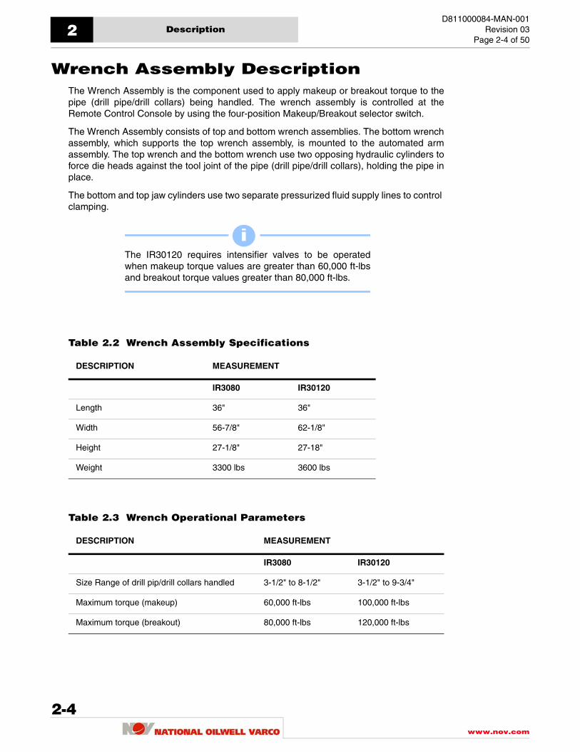
Checkout Procedures . . . . . . . . . . . . . . . . . . . . . . . . . . . . . . . . . . . . . . . . . . . . 3-13Installation Checkout Procedure . . . . . . . . . . . . . . . . . . . . . . . . . . . . . . . . . . . . 3-13HPU Installation Checkout procedure . . . . . . . . . . . . . . . . . . . . . . . . . . . . . . . . 3-13Controls Installation Checkout Procedure . . . . . . . . . . . . . . . . . . . . . . . . . . . . . 3-13Startup Checkout Procedure . . . . . . . . . . . . . . . . . . . . . . . . . . . . . . . . . . . . . . . 3-14System Setting Checkout Procedure . . . . . . . . . . . . . . . . . . . . . . . . . . . . . . . . . 3-14Limit Switches Settings Checkout Procedure . . . . . . . . . . . . . . . . . . . . . . . . . . . 3-15
Chapter 4: OperationControls And Settings . . . . . . . . . . . . . . . . . . . . . . . . . . . . . . . . . . . . . . . . . . . . . 4-1
Control System Description . . . . . . . . . . . . . . . . . . . . . . . . . . . . . . . . . . . . . . . . . 4-1Remote Control Console Start-up Procedure . . . . . . . . . . . . . . . . . . . . . . . . . . . . 4-4Limit Switch J-Box . . . . . . . . . . . . . . . . . . . . . . . . . . . . . . . . . . . . . . . . . . . . . . . . 4-5
Extend / Retract Limit Switch J-Box . . . . . . . . . . . . . . . . . . . . . . . . . . . . . . . . 4-5Setting Extend / Retract Limit Switch J-Box . . . . . . . . . . . . . . . . . . . . . . . . . . 4-6
Positioning the Iron Roughneck for Operation . . . . . . . . . . . . . . . . . . . . . . . . . . . 4-8Torque Setting Panel . . . . . . . . . . . . . . . . . . . . . . . . . . . . . . . . . . . . . . . . . . . . . . 4-9
Adjusting the Makeup Torque . . . . . . . . . . . . . . . . . . . . . . . . . . . . . . . . . . . . 4-10Adjusting the Jaw Pressure . . . . . . . . . . . . . . . . . . . . . . . . . . . . . . . . . . . . . 4-11Hydraulic Enclosure . . . . . . . . . . . . . . . . . . . . . . . . . . . . . . . . . . . . . . . . . . . 4-12
Hydraulic Rotation Column Assembly . . . . . . . . . . . . . . . . . . . . . . . . . . . . . . . . 4-14Rotate Column Assembly . . . . . . . . . . . . . . . . . . . . . . . . . . . . . . . . . . . . . . . . . . 4-15
Setting the Rotation Target Switches . . . . . . . . . . . . . . . . . . . . . . . . . . . . . . 4-15Rotation Manual Override . . . . . . . . . . . . . . . . . . . . . . . . . . . . . . . . . . . . . . . . . 4-16Rotation Manifold Override System . . . . . . . . . . . . . . . . . . . . . . . . . . . . . . . . . . 4-17
Makeup and Breakout Operations. . . . . . . . . . . . . . . . . . . . . . . . . . . . . . . . . 4-18Start-Up Procedures . . . . . . . . . . . . . . . . . . . . . . . . . . . . . . . . . . . . . . . . . . . . . . 4-18
Making Connections . . . . . . . . . . . . . . . . . . . . . . . . . . . . . . . . . . . . . . . . . . . . . 4-19Makeup Initial Position . . . . . . . . . . . . . . . . . . . . . . . . . . . . . . . . . . . . . . . . . . . . 4-19Normal Makeup Procedure . . . . . . . . . . . . . . . . . . . . . . . . . . . . . . . . . . . . . . . . 4-21
Breaking Connections . . . . . . . . . . . . . . . . . . . . . . . . . . . . . . . . . . . . . . . . . . . . 4-23Breakout Initial Position . . . . . . . . . . . . . . . . . . . . . . . . . . . . . . . . . . . . . . . . . . . 4-23Normal Breakout Procedure . . . . . . . . . . . . . . . . . . . . . . . . . . . . . . . . . . . . . . . . 4-25Emergency Stop Procedures . . . . . . . . . . . . . . . . . . . . . . . . . . . . . . . . . . . . . . . 4-27Start after Emergency Stop . . . . . . . . . . . . . . . . . . . . . . . . . . . . . . . . . . . . . . . . 4-27
Chapter 5: MaintenancePreventive Maintenance. . . . . . . . . . . . . . . . . . . . . . . . . . . . . . . . . . . . . . . . . . . 5-1
General Preventive Maintenance . . . . . . . . . . . . . . . . . . . . . . . . . . . . . . . . . . . . . 5-1Preventive Maintenance . . . . . . . . . . . . . . . . . . . . . . . . . . . . . . . . . . . . . . . . . . . . 5-2Preventive / Periodic Maintenance . . . . . . . . . . . . . . . . . . . . . . . . . . . . . . . . . . . . 5-3
Lubrication and Inspection . . . . . . . . . . . . . . . . . . . . . . . . . . . . . . . . . . . . . . . . 5-5Lubrication Schedule . . . . . . . . . . . . . . . . . . . . . . . . . . . . . . . . . . . . . . . . . . . . . . 5-5
iii

Table of Contents
D811000084-MAN-001Revision 03Page iv of iv
Wrench Lubrication . . . . . . . . . . . . . . . . . . . . . . . . . . . . . . . . . . . . . . . . . . . . 5-6Column-Guide-Arm Lubrication . . . . . . . . . . . . . . . . . . . . . . . . . . . . . . . . . . 5-7Automated Arm Lubrication . . . . . . . . . . . . . . . . . . . . . . . . . . . . . . . . . . . . . 5-9
Inspection Schedule . . . . . . . . . . . . . . . . . . . . . . . . . . . . . . . . . . . . . . . . . . . . . 5-10Wrench Inspection . . . . . . . . . . . . . . . . . . . . . . . . . . . . . . . . . . . . . . . . . . . 5-10Column-Guide-Arm Inspection . . . . . . . . . . . . . . . . . . . . . . . . . . . . . . . . . . 5-12Automated Arm Inspection . . . . . . . . . . . . . . . . . . . . . . . . . . . . . . . . . . . . . 5-13Spinner Assembly Inspection . . . . . . . . . . . . . . . . . . . . . . . . . . . . . . . . . . . 5-14Remote Control Console Inspection . . . . . . . . . . . . . . . . . . . . . . . . . . . . . . 5-16Day-to-Day Inspection . . . . . . . . . . . . . . . . . . . . . . . . . . . . . . . . . . . . . . . . 5-17
Safety Warnings And Precautions . . . . . . . . . . . . . . . . . . . . . . . . . . . . . . . . 5-18Recommended Lubricants And Fluids . . . . . . . . . . . . . . . . . . . . . . . . . . . . 5-21
Hydraulic Fluids . . . . . . . . . . . . . . . . . . . . . . . . . . . . . . . . . . . . . . . . . . . . . . . . 5-21General Maintenance . . . . . . . . . . . . . . . . . . . . . . . . . . . . . . . . . . . . . . . . . . . 5-23
Hazard Descriptions and Safeguards . . . . . . . . . . . . . . . . . . . . . . . . . . . . . . . . 5-23General Electrical Maintenance . . . . . . . . . . . . . . . . . . . . . . . . . . . . . . . . . . . . 5-24
General Switch Maintenance . . . . . . . . . . . . . . . . . . . . . . . . . . . . . . . . . . . 5-24Electrical Checks / Maintenance . . . . . . . . . . . . . . . . . . . . . . . . . . . . . . . . . 5-24Electrical Faults . . . . . . . . . . . . . . . . . . . . . . . . . . . . . . . . . . . . . . . . . . . . . . 5-24Major Repairs and Modifications . . . . . . . . . . . . . . . . . . . . . . . . . . . . . . . . . 5-24
Iron Roughneck General Maintenance . . . . . . . . . . . . . . . . . . . . . . . . . . . . . . . 5-25Cleaning . . . . . . . . . . . . . . . . . . . . . . . . . . . . . . . . . . . . . . . . . . . . . . . . . . . 5-25Lubrication Schedule . . . . . . . . . . . . . . . . . . . . . . . . . . . . . . . . . . . . . . . . . 5-25Replacement of Wear Parts . . . . . . . . . . . . . . . . . . . . . . . . . . . . . . . . . . . . 5-25Main Overhaul . . . . . . . . . . . . . . . . . . . . . . . . . . . . . . . . . . . . . . . . . . . . . . . 5-25Hydraulic Hose and Fittings . . . . . . . . . . . . . . . . . . . . . . . . . . . . . . . . . . . . 5-25
Functional Testing Maintenance . . . . . . . . . . . . . . . . . . . . . . . . . . . . . . . . . . . . 5-26General Storage Guidelines . . . . . . . . . . . . . . . . . . . . . . . . . . . . . . . . . . . . . . 5-27
General Storage . . . . . . . . . . . . . . . . . . . . . . . . . . . . . . . . . . . . . . . . . . . . . . . . 5-27Storing and Preservation of Equipment . . . . . . . . . . . . . . . . . . . . . . . . . . . 5-27Long Term Storage of Iron Roughneck Equipment . . . . . . . . . . . . . . . . . . 5-27Initial Storage Procedures . . . . . . . . . . . . . . . . . . . . . . . . . . . . . . . . . . . . . . 5-29Storage Removal Procedures . . . . . . . . . . . . . . . . . . . . . . . . . . . . . . . . . . . 5-30 Preparing Equipment for Operation After Storage . . . . . . . . . . . . . . . . . . . 5-30
Major Component Maintenance . . . . . . . . . . . . . . . . . . . . . . . . . . . . . . . . . . 5-31Wrench Assembly Maintenance . . . . . . . . . . . . . . . . . . . . . . . . . . . . . . . . . . . . 5-31
Replacing Dies in Top and Bottom Wrench Assemblies . . . . . . . . . . . . . . . 5-31Remote Control Console Maintenance . . . . . . . . . . . . . . . . . . . . . . . . . . . . . . . 5-33
Specified Cleaning Methods . . . . . . . . . . . . . . . . . . . . . . . . . . . . . . . . . . . . 5-33
Chapter 6: TroubleshootingTroubleshooting Categories . . . . . . . . . . . . . . . . . . . . . . . . . . . . . . . . . . . . . . 6-2
Identifying Troubleshooting Categories . . . . . . . . . . . . . . . . . . . . . . . . . . . . . . . 6-2Mechanical Components . . . . . . . . . . . . . . . . . . . . . . . . . . . . . . . . . . . . . . . 6-2Hydraulic Circuits and Valves . . . . . . . . . . . . . . . . . . . . . . . . . . . . . . . . . . . . 6-2Electrical and Control System Components . . . . . . . . . . . . . . . . . . . . . . . . . 6-2
Troubleshooting Operation Problems. . . . . . . . . . . . . . . . . . . . . . . . . . . . . . 6-3
www.nov.com
iv

D811000084-MAN-001Revision 03
Page 1-1 of 4
General Information
ConventionsThis manual is intended for use by field engineering, installation, operation, and repairpersonnel. Every effort has been made to ensure the accuracy of the informationcontained herein. National Oilwell Varco (NOV), will not be held liable for errors in thismaterial, or for consequences arising from misuse of this material.
Notes, Cautions, and WarningsNotes, cautions, and warnings provide readers with additional information, and to advisethe reader to take specific action to protect personnel from potential injury or lethalconditions. They may also inform the reader of actions necessary to prevent equipmentdamage. Please pay close attention to these advisories.
Note:
Caution:
Warning:
iiThe note symbol indicates that additional information isprovided about the current topic.
!The caution symbol indicates that potential damage toequipment, or injury to personnel exists. Followinstructions explicitly. Extreme care should be taken whenperforming operations or procedures preceded by thiscaution symbol.
The warning symbol indicates a definite risk ofequipment damage or danger to personnel. Failure tofollow safe work procedures could result in serious orfatal injury to personnel, significant equipmentdamage, or extended rig down time.
www.nov.com
1-1

General Information1D811000084-MAN-001
Revision 03Page 1-2 of 4
IllustrationsIllustrations (figures) provide a graphical representation of equipment components orscreen snapshots for use in identifying parts, or establishing nomenclature, and may ormay not be drawn to scale.
For component information specific to your rig configuration, see the technical drawingsincluded with your Varco documentation.
www.nov.com
1-2

D811000084-MAN-001Revision 03Page 1-3 of 4
General Information 1
Safety RequirementsThe National Oilwell Varco equipment is installed and operated in a controlled drilling rigenvironment involving hazardous situations. Proper maintenance is important for safe andreliable operation. Procedures outlined in the equipment manuals are the recommendedmethods of performing operations and maintenance.
Personnel TrainingAll personnel performing installation, operations, repair, or maintenance procedures on theequipment, or those in the vicinity of the equipment, should be trained on rig safety, tooloperation, and maintenance to ensure their safety.
Contact the National Oilwell Varco training department for more information aboutequipment operation and maintenance training.
Recommended ToolsService operations may require the use of tools designed specifically for the purposedescribed. The equipment manufacturer recommends that only those tools specified beused when stated. Ensure that personnel and equipment safety are not jeopardized whenfollowing service procedures and that personnel are not using tools that were notspecifically recommended by the manufacturer.
!To avoid injury to personnel or equipment damage,carefully observe requirements outlined in this section.
!Personnel should wear protective gear during installation,maintenance, and certain operations.
1-3www.nov.com

General Information1D811000084-MAN-001
Revision 03Page 1-4 of 4
General System Safety PracticesThe equipment discussed in this manual may require or contain one or more utilities suchas electrical, hydraulic, pneumatic, or cooling water.
Isolate energy sources before beginning work.
Avoid performing maintenance or repairs while the equipment is in operation.
Wear proper protective equipment during equipment installation, maintenance, or repair.
Replacing ComponentsVerify that all components (such as cables, hoses, etc.) are tagged and labeled during assembly and disassembly of equipment to ensure correct installment.
Replace failed or damaged components with original equipment manufacturer certified parts. Failure to do so could result in equipment damage or injury to personnel.
Routine MaintenanceEquipment must be maintained on a routine basis. See product-specific service manualsfor maintenance recommendations.
Proper Use of EquipmentNational Oilwell Varco equipment is designed for specific functions and applications, andshould be used only for its intended purpose.
!Read and follow the guidelines below before installingequipment or performing maintenance to avoidendangering exposed persons or damaging equipment.
!Failure to conduct routine maintenance could result inequipment damage or injury to personnel.
www.nov.com
1-4

D811000084-MAN-001Revision 03
Page 2-1 of 50
Description
General DescriptionThis Operation and Maintenance Manual describes the day-to-day care and operation ofthe Iron Roughneck. It is essential that the equipment operators have the requiredknowledge, education and training before using the system.
The Iron Roughneck is a lightweight, compact, modular roughneck, which is mounted onthe rig floor and uses a hydraulic powered Automated Arm Assembly (patent pending) toextend the roughneck, toward the mouse hole or well center, or retract the roughneck backto the standby / park position. A column assembly allows the roughneck to move in avertical direction, as well as allowing it to rotate to align with either the mouse hole or wellcenter. An Extend/Retract Limit Switch J-box mounted on the column is used to selecteither the mouse hole or the well center as the destination for the Iron Roughneck. Thisswitch determines the reach distance by the Automated Arm assembly. A locking pin in thecolumn allows the operator to manually rotate the Iron roughneck to face either the mousehole or well center.
The Iron Roughneck is capable of performing makeup and breakout operations using anyof a number of different size drill pipe/drill collars ranging from 3.5" to 8.5" (3.5" to 9.75" ifequipped with IR30120 wrenches) nominal drill pipe/drill collars size with one set of V-dies. The Iron Roughneck system’s makeup and breakout tools are hydraulic pressureoperated. The spinner assembly, which utilizes a floating suspension system, allows thespinner assembly to follow drill pipe/drill collars movement as threaded connections arespun in or out. The torque wrench assembly, which utilizes a combination top wench andbottom wrench assemblies, apply the clamp force and rotational force to hold and rotatethe drill pipe/drill collars to allow makeup or breakout the connections.
The Iron Roughneck uses an operator-controlled, electrically powered Remote ControlConsole (RCC) located several feet away from the roughneck. A Hydraulic Enclosure(HE), mounted on the frame of the Iron Roughneck, is available for use during setting oftorque and clamp pressure or during maintenance periods when the RCC is not available.The HE is located on the Iron Roughneck. A Torque Setting Panel is mounted on top of theHE. The Torque Setting Panel is used to adjust the torque setting for the Torque Wrenchassembly.
www.nov.com
2-1
D811001123-GEN-001/02

Description2D811000084-MAN-001
Revision 03Page 2-2 of 50
Figure 2-1. Typical Iron Roughneck Major Assemblies
SPINNER ROTATION
BOTTOM JAW
MAKE UP
FT LB250
SPINNER
GRIP
COMPLETEMAKEUP
MAKEUPREPEAT
OFF
BREAKOUT
3
START
OPEN
0
x100
SPIN
*
MAKEUP TORQUE
OUT
300 PSI
IR MOVE
WRENCH
E−STOP
2
CLOSE
1DOWN
OUT
UP
IN
x10
SYSTEM PRESS
IN Remote ControlConsole
ArmAssembly
SpinnerAssembly
Torque WrenchAssembly
Torque Setting Panel
Hydraulic Enclosure
ERLS J-Box
RN 300018
www.nov.com
2-2

D811000084-MAN-001Revision 03Page 2-3 of 50
Description 2
Table 2.1 Typical Iron Roughneck Major Assemblies
COMPONENT DESCRIPTION
Torque Wrench Assembly
The Torque Wrench is a combination assembly of a top wrench and bottom wrench. The top wrench rotates relative to the bottom wrench by a single hydraulic cylinder. Each wrench has two hydraulic cylinders directly connected to jaw clamping dies. When two sections of pipe are being made-up or broken out, this applies torque to the upper section of pipe.
Spinner Assembly
The Spinner Assembly is an integrated hydraulic powered roller assembly for rotating pipe connections. The Spinner assembly utilizes upper and lower rollers that are hydraulic motor driven. The spinner assembly is spring suspended for self-adjustment on the pipe, which allows the spinner assembly to follow drill pipe/drill collars movement as threaded connections are spun in or out.
Column-Guide-Arm Assembly
The Automated Arm assembly is a folding arm that is used for horizontal movement to extend and retract the roughneck’s Spinner/Wrench assemblies. The Automated arm allows horizontal movement to the two adjustable locations (mousehole and well center) from the standby park position. A hydraulic lift cylinder on the Automated Arm column allows vertical movement of the Automated Arm Assembly.
Controls
Remote Control Console is used to remotely control the Iron Roughneck.
Hydraulic Enclosure contains the electro- hydraulic control valves. The electro hydraulic control system can be remotely controlled from the remote console, or locally controlled at the electro-hydraulic control manifold.
Torque Setting Panel is used to adjust make-up torque limits. A local emergency shutdown is also located on the Torque Setting Panel.
ERLS J-Box is used to select mousehole or well center as the destination of the roughneck.
Hydraulic Power UnitThe Hydraulic Power Unit supplies hydraulic power at 3000 psi to the Roughneck.
2-3www.nov.com
Description2D811000084-MAN-001
Revision 03Page 2-4 of 50
Wrench Assembly DescriptionThe Wrench Assembly is the component used to apply makeup or breakout torque to thepipe (drill pipe/drill collars) being handled. The wrench assembly is controlled at theRemote Control Console by using the four-position Makeup/Breakout selector switch.
The Wrench Assembly consists of top and bottom wrench assemblies. The bottom wrenchassembly, which supports the top wrench assembly, is mounted to the automated armassembly. The top wrench and the bottom wrench use two opposing hydraulic cylinders toforce die heads against the tool joint of the pipe (drill pipe/drill collars), holding the pipe inplace.
The bottom and top jaw cylinders use two separate pressurized fluid supply lines to control clamping.
Table 2.2 Wrench Assembly Specifications
Table 2.3 Wrench Operational Parameters
iiThe IR30120 requires intensifier valves to be operatedwhen makeup torque values are greater than 60,000 ft-lbsand breakout torque values greater than 80,000 ft-lbs.
DESCRIPTION MEASUREMENT
IR3080 IR30120
Length 36" 36"
Width 56-7/8" 62-1/8"
Height 27-1/8" 27-18"
Weight 3300 lbs 3600 lbs
DESCRIPTION MEASUREMENT
IR3080 IR30120
Size Range of drill pip/drill collars handled 3-1/2" to 8-1/2" 3-1/2" to 9-3/4"
Maximum torque (makeup) 60,000 ft-lbs 100,000 ft-lbs
Maximum torque (breakout) 80,000 ft-lbs 120,000 ft-lbs
www.nov.com
2-4

D811000084-MAN-001Revision 03Page 2-5 of 50
Description 2
Figure 2-2. Typical IR3080 Wrench Assembly
BOTTOM WRENCHASSEMBLY
FrontWear Block
View withBW top plate
RearWear Block
Die Holder
View withoutBW top plate
Lock Plates
Cylinder
Stop Pin
Rod Pin
Bottom JawManifold
Jaw Dies(WD4)
RN300022
Cylinder
CylinderStop
BWBody
Weldment
Torque CylinderAssembly
FrontWear Block
Top WrenchAssembly
2-5www.nov.com

Description2D811000084-MAN-001
Revision 03Page 2-6 of 50
Figure 2-3. Typical IR30120 Wrench Assembly
RearWear Block
FrontWear Block
View withtop plate
FrontWear Block
BOTTOM WRENCHASSEMBLY
Die Holder
View withouttop plate
Lock Plates
Cylinder
Stop Pin
Rod Pin
Bottom JawManifold
Cylinder
CylinderStop
BWBody
Weldment
Torque Cylinder
Top WrenchAssembly
Top WrenchIntensifier
Jaw Dies
RN300066
www.nov.com
2-6

D811000084-MAN-001Revision 03Page 2-7 of 50
Description 2
This page is intentionally left blank.
2-7www.nov.com

Description2D811000084-MAN-001
Revision 03Page 2-8 of 50
Spinner Assembly Description
Spinner AssemblyThe Spinner is mounted above the Wrench Assembly (see Figure 2.1) and is used to spina drill pipe/drill collar connection IN prior to makeup torquing, and spin a drill pipe/drillcollar connection OUT after breakout torquing.
The pipe spinner has four sets of two drive rollers each. Two hydraulic motors drive eachset. This system can reach and centralize any diameter drill pipe/drill collar between 3-1/2"to 8-1/2" size. The clamping is done with one hydraulic cylinder.
Spinner Support AssemblyThe Spinner Support Assembly (see Figure 2.4), which supports the Spinner Assembly issocket mounted to the Wrench Frame Assembly. The Spinner Support assembly, whichutilizes a floating suspension system, allows the spinner assembly to follow drill pipe/drillcollars movement as threaded connections are spun in or out.
Table 2.6 Pipe Spinner Assembly Specifications
Table 2.7 Pipe Spinner Operational Parameters
DESCRIPTION MEASUREMENT
Length 36-5/8"
Width 35"
Height 26-1/2"
Weight 1250 lbs
Hydraulic Pressure Line 3/4" ID
Hydraulic Return Line 3/4" ID
DESCRIPTION MEASUREMENT
Size Range of drill pipe/drill collars handled 3-1/2" to 9-3/4"
Maximum Spinner rpm 80 rpm (On 5-1/2" Drill Pipe)
Maximum Spinner Torque 2250 ft-lbs
www.nov.com
2-8

D811000084-MAN-001Revision 03Page 2-9 of 50
Description 2
Figure 2-4. Spinner and Support Assembly
Balance Spring
Wrench FrameInterlockPin Hole
Head Support
RN300023
Spring AssemblyLower Pin
Spinner Assembly
Spring Suspesion AssemblySpring Assembly
Upper Pin
2-9www.nov.com

Description2D811000084-MAN-001
Revision 03Page 2-10 of 50
Column-Guide-Arm Assembly
Description The column-guide-arm assembly is a mechanical positioning unit of the Iron Roughnecksystem. At various times during drilling operations, the Iron Roughneck System needs tobe moved between several locations on the rig, including the well centerline, one or moremouse holes, and a parking or storage position. The Iron Roughneck's positioningmovements are achieved by the column-guide-arm assembly.
The column-guide-arm assembly provides the vertical and horizontal movement of theIron Roughneck. All extend, retract, or lift operational movements for positioning the IronRoughneck systems to the rig positions, are controlled through a remote electro-hydrauliccontrol system, or by the onboard manual override hydraulic control system. Additionally,the automated arm section of the column-guide-arm assembly holds the wrench assemblyin the vertical position at all extension points.
General ArrangementThe Iron Roughneck's Column-Guide-Arm Assembly consists of the following assembliesand components: Column Assembly; Guide Assembly; Arm Assembly; and hydrauliccomponents.
The column assembly consists of a column base, column weldment and column turntablebearing. The column bearing is mounted directly between the column base and columnweldment surfaces. Equipped on some models is a turntable bearing with an external gearfor Column Rotation Systems. The column assembly is attached into the drill floor bymeans of the column base that is stabbed into a socket mount in the rig floor.
The guide assembly is mounted over the column structure and a self-balanced, automatedarm assembly is attached to the column guide assembly at a first connection point with awrench assembly attached at a second connection point. A pair of hydraulic cylinders isused for extension and retraction of the arm assembly and a single trunnion mountedcylinder is used for the guide assembly lift.
Hydraulic circuit components properties vary on some models refer to the hydraulicschematic diagram in the parts list section of the manual for rig specific column-guide-armhydraulic circuit components.
www.nov.com
2-10

D811000084-MAN-001Revision 03Page 2-11 of 50
Description 2
Figure 2-5. Typical Column/Guide/Arm Assembly General Arrangement
2-11www.nov.com

Description2D811000084-MAN-001
Revision 03Page 2-12 of 50
Figure 2-6. Typical Column Assemblies
www.nov.com
2-12

D811000084-MAN-001Revision 03Page 2-13 of 50
Description 2
Major Component DescriptionColumn Assembly
The column assembly provides four key functions to the operations of the Iron Roughneck:
1. The Iron Roughneck's column base assembly is mounted into the drill floor socket, which provides structural support for the Iron Roughneck.
2. The column structure lower end provides an attachment point for the guide assembly lift cylinder.
3. The column weldment is fitted with two track rails to support the guide frame weldment and to provide a guiding surface on which the guide assembly cam follower bearings ride against for vertical travel.
4. When in a connection operations the column's turntable bearing allows the Iron Roughneck system to be positioned easily between orientation points of well center, mousehole, and park position.
Rotate Column Assembly
Some IR models are equipped with a remote hydraulic rotation column system (see Figure2.6). This feature allows the Iron Roughneck to be hydraulic rotated around the turntableuntil it stops automatically at one of the rotation index position points (well center ormousehole).
To rotate the column assembly, hydraulic power is applied to the drive motor, which in turndrives the pinion gear. Since the ring gear bearing assembly is bolted directly between thecolumn base and column weldment seating surfaces the pinion gear and drive motorrotate around the ring gear, which allows for precise positioning and stopping around thecolumn assembly.
The column rotation system consists of a column structure weldment with a drive motormounting, a hydraulic drive motor with brake, a pinion gear and ring gear. The ring gear ispart of the turntable bearing assembly. The column rotation system brake is used to holdthe Iron Roughneck's column assembly in a park position during connection operationsare being preformed.
2-13www.nov.com

Description2D811000084-MAN-001
Revision 03Page 2-14 of 50
Figure 2-7. Arm Assembly
www.nov.com
2-14

D811000084-MAN-001Revision 03Page 2-15 of 50
Description 2
Arm Assembly
The Iron Roughneck's Automated Arm assembly utilizes a hydraulic self-balanced, dualsynchronized four-sided arm assembly that is equipped with two hydraulic cylinders, toextend or retract the arm links, and one hydraulic cylinder to lift the guide assembly. TheIron Roughneck Automated Arm Assembly allows Iron Roughneck's wrench and spinnerassemblies to be positioned horizontally and vertically during drilling operations.
The Iron roughneck's Arm Assembly Links are a group of linking arms that are connectedin a parallel linking arrangement consisting of six link arms that are joined to a centerconnecting weldment that hold the link arms parallel with a common axis. The ArmAssembly Links allow the Iron Roughneck's wrench and spinner assemblies to reachmaximum extension distance and rotation points between well center, mousehole, andparking positions.
The Arm Assembly Links allow the Iron Roughneck's Automated Arm Assembly to travel ina linear direction parallel to the drill floor, and allows the Automated Arm Assembly toretract into a compact envelope to park the Iron Roughneck wrench and spinnerassemblies during drilling operations.
Figure 2-8. Automated Arm Retract and Extend Positions
2-15www.nov.com

Description2D811000084-MAN-001
Revision 03Page 2-16 of 50
Guide Assembly
The Guide Assembly provides two key functions to the operation of the Iron Roughnecksystem. First, the Guide Assembly lifts the Iron Roughneck tools vertically, and in additionalso transfers the Iron Roughneck load to the column structure. The hydraulic cylinderprovided with the column-guide-arm assembly is used to perform the guide assemblylifting operations. Secondly the Guide Assembly provides the pivotal connection points forthe Arm Assembly Links and extend-retract hydraulic cylinders.
The guide assembly which is directly mounted to the column structure consists of a guideweldment frame with four cam follower bearings and wear pads. The Guide frame guidepads are dimensionally space against the column guide track for cam follower bearingalignment and loading. The trunnion mounted lift cylinder that lifts the guide assemblyvertically along the column's guide tracks is attached to guide frame at one connectionpoint with lift cylinder's second connection point attached at the column weldment base.
Figure 2-9. Typical Guide Fram Assembly
www.nov.com
2-16

D811000084-MAN-001Revision 03Page 2-17 of 50
Description 2
Hydraulic Circuit Components
Inline Hydraulic High-Pressure Filter
Mounted on the guide frame assembly directly below the lower left link assembly is aninline hydraulic high pressure filter assembly with a visual indicator. The Iron Roughneck'sonboard hydraulic high pressure filter assembly is immediately down stream from the IronRoughneck's hydraulic inlet connection. The inline hydraulic high pressure filter is used tofilter the hydraulic supply fluid prior to circulating through the Iron Roughneck's hydrauliccomponents.
Wrench Lift Cylinder
Mounted on the guide frame assembly is a Lift Cylinder, which is used to lift the guideassembly vertically to position the Iron Roughneck wrench and spinner assemblies.
Wrench Lift Manifold Assembly
Mounted down stream from the lift cylinder is a wrench lift manifold assembly withcartridge type relief valve, counterbalance valve and flow valve. The relief valve is used toset the "up load" hydraulic pressure setting to the lift cylinder. The counterbalance valve, isused to prevent an "over running" load from moving the lift cylinder. The flow valve, is usedregulate the hydraulic flow to the lift cylinder.
Move In-Out Cylinders
Mounted on the guide frame assembly are two hydraulic cylinders, which are used toextend or retract the automated arm assembly.
Move In-Out Manifold Assembly
Mounted down stream from the move in-out cylinders is a move in-out manifold assemblywith cartridge type cross over relief valves and pilot operated check valve. The cross-overrelief valves are used to set extend and retract hydraulic pressure setting to the move in-out cylinders. The pilot operated check valve in the move in-out manifold assembly is usedto hold the load. Mounted down stream from the move in-out manifold assembly on eachside of the move in-out hydraulic circuit are two needle valves. The primary functions ofthe needle valves are to regulate the hydraulic flow to the move in-out cylinders. Theneedle valves are factory set and normally no further adjustment is required unless themove in-out cylinders and/or the valves has been serviced or repaired.
iiIron Roughneck equipment features may vary on somemodels. Refer to the hydraulic schematic diagram in theparts list section of this manual for IR hydrauliccomponents requirements.
2-17www.nov.com

Description2D811000084-MAN-001
Revision 03Page 2-18 of 50
Rotation Manifold Assembly
Mounted on the guide frame assembly on some models is a rotation manifold assembly, which is used to control the column assembly hydraulic rotation circuit. The rotation manifold assembly is an integrated hydraulic manifold with directional valves, counterbalance valves, shuttle valves .pressure reducing relief valve and a hand pump for manual override to allow rotation operations to be controlled locally at the rotation manifold assembly.
www.nov.com
2-18

D811000084-MAN-001Revision 03Page 2-19 of 50
Description 2
IR3080 with 88" Arm Assembly
Automated Arm Assembly
Figure 2-10. Automated Arm Assembly
2-19www.nov.com

Description2D811000084-MAN-001
Revision 03Page 2-20 of 50
Automated Arm AssemblyThe Iron Roughneck Automated Arm Assembly consists of the following main assembliesand components: Link Assembly; Guide Assembly; Vertical Track Assembly, and hydrauliccomponents.
The Iron Roughneck's Automated Arm assembly utilizes a hydraulic self-balanced, dualsynchronized four-sided arm assembly that is equipped with two hydraulic cylinders, toextend or retract the arm links, and one hydraulic cylinder to lift the guide assembly. TheIron Roughneck Automated Arm Assembly allows Iron Roughneck's wrench and spinnerassemblies to be positioned horizontal and vertical during drilling operations.
Figure 2-11. Automated Arm Retract and Extend Positions
www.nov.com
2-20

D811000084-MAN-001Revision 03Page 2-21 of 50
Description 2
Link AssemblyThe Iron roughneck's Link Assembly is a group of linking arms that are connected in aparallel linking arrangement consisting of five link arms that are joined to a centerconnecting weldment that hold the link arms parallel with a common axis. The LinkAssembly allows the Iron Roughneck's wrench and spinner assemblies to reach maximumextension distance and rotation points between well center, mousehole, and parkingpositions.
The Link Assembly allows the Iron Roughneck's arm assembly to travel in a lineardirection parallel to the drill floor, and allows the link assembly to retract into a compactenvelope to park the Iron Roughneck wrench and spinner assemblies during drillingoperations.
Figure 2-12. Link Assembly
2-21www.nov.com

Description2D811000084-MAN-001
Revision 03Page 2-22 of 50
Link Assembly with Tilting Feature
The Link Arm Assembly with titling feature (if equipped) enables the lower right linkassembly to pivot the Iron Roughneck's wrench and spinner assemblies from the verticalposition to tilted axis angle position, for mousehole alignment.
The tilting hydraulic circuit consists of two hydraulic tilting cylinders that are mounted to thelower right link assembly that are hydraulic energized when the hydraulic limit valve istriggered. The hydraulic flow to the tilting cylinders is maintained and regulated by anupstream mounted needle valve.
The pivot axis angle of the automated arm's titling system is controlled by the mechanicalpositioning target bracket that is mounted on the automated arm assembly to target andtrigger the hydraulic limit valve. The hydraulic limit valve is triggered when the Ironroughneck's link arm is extended beyond the set point of the well center. The IronRoughneck's wrench and spinner assembly return to a vertical position when theautomated arm assembly is retracted to the set point of well center, or when theautomated arm is retracted to the parking position.
Figure 2-13. Link Assembly with Tilting Feature
www.nov.com
2-22

D811000084-MAN-001Revision 03Page 2-23 of 50
Description 2
Guide AssemblyThe Guide Assembly provides two key functions to the operation of the Iron Roughneck.First, the Guide Assembly guides the Iron Roughneck vertically, and in addition alsotransfers the Iron Roughneck load to the vertical track assembly. The Guide Assemblyuses four cam followers and four guide pads dimensionally spaced against the verticaltrack assembly, which allows the guide assembly to guide the Iron roughneck along thevertical tracks. Second, the Guide Assembly provides the pivotal connection points for theAutomated Arm Links and hydraulic cylinders. Attached to the Guide Assembly are twohydraulic manifold assemblies (See Figure 2.19) the cross-port relief and the move in-outrelief manifolds.
Figure 2-14. Guide Assembly
2-23www.nov.com

Description2D811000084-MAN-001
Revision 03Page 2-24 of 50
Vertical Track AssemblyThe Vertical Track Assembly provides four key functions to the operations of the IronRoughneck. First, the Iron Roughneck's vertical track assembly's base is mounted into thedrill floor socket, which provides structural support for the Iron Roughneck. Second, thevertical track assembly's rotating bearing allows the Iron Roughneck to be positionedeasily between orientation points of well center, mousehole, and parking positions. Third,the Vertical Track Assembly provides attachment points for the Guide Assembly liftcylinders. Four, the Vertical Track Assembly is fitted with four corner track rails, which allowthe cam follower to move in a smooth and linear travel.
Figure 2-15. Vertical Track Assembly
www.nov.com
2-24

D811000084-MAN-001Revision 03Page 2-25 of 50
Description 2
Automated Arm Hydraulic Circuit Components
Figure 2-16. Hydraulic Circuit Components
2-25www.nov.com

Description2D811000084-MAN-001
Revision 03Page 2-26 of 50
Automated Arm Hydraulic Circuit Components
Inline Hydraulic High-Pressure Filter
Mounted on the guide assembly weldment directly below the lower left link assembly is aninline hydraulic high pressure filter assembly with a visual indicator. The Iron Roughneck'sonboard hydraulic high pressure filter assembly is immediately down stream from the IronRoughneck's hydraulic inlet connection. The inline hydraulic high pressure filter is used tofilter the hydraulic supply fluid prior to circulating through the Iron Roughneck's hydrauliccomponents.
Lift Cylinder
Mounted on the guide assembly weldment is a Lift Cylinder, which is used to lift the guideassembly vertically to position the Iron Roughneck wrench and spinner assemblies.Mounted on the lift cylinder on the "UP" side is a counterbalance valve. The primaryfunction of the counterbalance valve is to prevent an "over running" load from moving thecylinder. The counterbalance valve is factory set and normally no further adjustment isrequired unless the lift cylinder and /or the valve has been serviced or repaired.
Lift Cylinder Cross Port Relief Valve (if equipped)
Mounted down stream from the lift cylinder is a cross over port relief valve, which is usedto set the up and down pressure setting of the hydraulic lift cylinder.
Linkage Cylinders
Mounted on the guide assembly weldment are two hydraulic cylinders, which are used toextend or retract the automated arm assembly.
Move In-Out Cylinders and Manifold Valve (if equipped)
The hydraulic valve connected to the move in-out cylinders is a relief valve, which is usedto set the retract pressure setting of the hydraulic move in-out cylinders. Mounted on themove in-out cylinders on the "MOVE-IN" side are counterbalance valves. The primaryfunction of the counterbalance valve is to prevent an "over running" load from moving thecylinder. The counterbalance valve is factory set and normally no further adjustment isrequired unless the move in-out cylinders and/or the valves has been serviced or repaired.
www.nov.com
2-26

D811000084-MAN-001Revision 03Page 2-27 of 50
Description 2
Remote Control Console DescriptionThe remote control console (RCC) shown in Figure 2.20 is typical of those provide byNational Oilwell Varco. The operator can perform makeup and breakout of drill pipe/drillcollar connections using the RCC. The RCC is either freestanding on the drill floor orlocated in or close to the Driller's Cabin, and positioned to where the jaws of the IR can beobserved while operating the Iron Roughneck. The remote control console panel containsthe IR selector switches, Emergency stop pushbutton switch, status lamps, and readoutsto operate the Iron Roughneck.
The remote control console (RCC) contains the control circuitry that controls themovements of various mechanical components of the Iron Roughneck. All operationalmovements of the IR are controlled by one operator. These movements are controlled byappropriate inputs from the operator's remote control console (RCC) and positioning limitsensors.
The IR operator can perform following actions from the remote control console (RCC):
Extend or retract the IR automated arm assembly.
Raise or lower the wrench assembly.
Clamp or unclamp the bottom or top jaws.
Actuate the make and break torque cylinder.
Actuate the grip rollers and rotation of the spinner assembly.
Stop the IR and shutdown the hydraulic and electrical systems.
All signal, control and power wiring connect to the RCC enters and leaves through thecable entry ports of the cabinet. A 24 VDC, 10 AMP, power supply source is connected tothe RCC, and the plug and cable assembly connects the RCC to the Iron Roughnecksolenoid J-Box. Refer to the electrical control system documentation and electricaldiagrams for detail electrical information.
iiJaw pressure setting is controlled from the torque settingpanel.
2-27www.nov.com

Description2D811000084-MAN-001
Revision 03Page 2-28 of 50
Figure 2-17. Remote Control Console
www.nov.com
2-28

D811000084-MAN-001Revision 03Page 2-29 of 50
Description 2
Technical Specifications
Iron Roughneck Technical Specifications
Table 2.11 Iron Roughneck Products
IRON ROUGHNECK WRENCH PACKAGE ARM LENGTH AUTO-ROTATION
TOP LEVEL NUMBER 3080 30120 55" 88" YES NO
1100005 x x x
1100006 x x x
1100011 x x x
1100012 x x x
1100014 x x x
1100016 x x x
1100017 x x x
1100018 x x x
2-29www.nov.com

Description2D811000084-MAN-001
Revision 03Page 2-30 of 50
IR3080 with 55" Arm
General SpecificationsTable 2.12 80K / 55" IR3080 Components
Utility RequirementsTable 2.13 80K / 55" IR3080 Utility Requirements
DESCRIPTION MEASUREMENT
Weight 7,600 (3,447 kg)
Spinner Drill Pipe/Collar Capacity 3.5" - 8.5"
Spin Speed (5" pipe dia.) 80 rpm
Spin Torque 2,250 ft-lbs (3,050 N-m)
Wrench Drill Pipe/Collar Capacity 3.5" - 8.5"
Makeup Torque (maximum) 60,000 ft-lbs (81,349 N-m)
Breakout Torque (maximum) 80,000 ft-lbs (108,465 N-m)
Connection Height (maximum) 68" (172.72 cm) maximum
Connection Height (minimum) 30" (76.2 cm) minimum
Horizontal Travel 55.5" (141 cm)
Vertical Travel 38" (96.5 cm)
UTILITY MEASUREMENT
Hydraulic System Pressure 3000 psi (206.8 bar)
Hydraulic System Flow rate 40 gpm (151 Ipm)
Electrical Control Requirements 24VDC (w/customer supplied HPU)
www.nov.com
2-30

D811000084-MAN-001Revision 03Page 2-31 of 50
Description 2
IR3080 / 55" Size Specifications
Maximum Extend, Side Dimensions
ALL DIMENSIONS ARE IN INCHES.
ALL DIMENSIONS IN BRACKETS ARE IN CENTIMETERS,
UNLESS OTHERWISE SPECIFIED.
Figure 2-18. IR3080 / 55" Maximum Extend, Side Dimensions
RN300076
Rig Floor
29 1/16 [73.78] REF
75 3/4 [192.41] REF
11 9/16 [29.37]
Fully Extended Side View
30 [76.20]
100 15/16 [256.40]
55 9/16 [141.09]
2-31www.nov.com

Description2D811000084-MAN-001
Revision 03Page 2-32 of 50
IR3080 / 55" Size Specifications
Maximum Extend, Maximum Lift, Side Dimensions
ALL DIMENSIONS ARE IN INCHES.
ALL DIMENSIONS IN BRACKETS ARE IN CENTIMETERS,
UNLESS OTHERWISE SPECIFIED.
Figure 2-19. IR3080 / 55" Maximum Extend, Maximum Lift, Side Dimensions
www.nov.com
2-32

D811000084-MAN-001Revision 03Page 2-33 of 50
Description 2
IR3080 / 55" Size Specifications
Maximum Extend, Top Dimensions
ALL DIMENSIONS ARE IN INCHES.
ALL DIMENSIONS IN BRACKETS ARE IN CENTIMETERS,
UNLESS OTHERWISE SPECIFIED.
Figure 2-20. IR3080 / 55" Maximum Extend, Top Dimensions
2-33www.nov.com

Description2D811000084-MAN-001
Revision 03Page 2-34 of 50
IR3080 / 55" Size Specifications
Maximum Retract, Side Dimensions
ALL DIMENSIONS ARE IN INCHES.
ALL DIMENSIONS IN BRACKETS ARE IN CENTIMETERS,
UNLESS OTHERWISE SPECIFIED.
Figure 2-21. IR3080 / 55" Maximum Retract, Side Dimensions
www.nov.com
2-34

D811000084-MAN-001Revision 03Page 2-35 of 50
Description 2
IR3080 with 88" Arm
General SpecificationsTable 2.14 80K / 88" IR3080 Components
Utility RequirementsTable 2.15 80K / 88" IR3080 Utility Requirements
DESCRIPTION MEASUREMENT
Weight 10,000 (4,536 kg)
Spinner Drill Pipe/Collar Capacity 3.5" - 8.5"
Spin Speed (5" pipe dia.) 80 rpm
Spin Torque 2,250 ft-lbs (3,050 N-m)
Wrench Drill Pipe/Collar Capacity 3.5" - 8.5"
Makeup Torque (maximum) 60,000 ft-lbs (81,349 N-m)
Breakout Torque (maximum) 80,000 ft-lbs (108,465 N-m)
Connection Height (maximum) 73.5" (186.8 cm) maximum
Connection Height (minimum) 35.5" (90.2 cm) minimum
Horizontal Travel 88.4" (224.6 cm)
Vertical Travel 38" (96.5 cm)
UTILITY MEASUREMENT
Hydraulic System Pressure 3000 psi
Hydraulic System Flow rate 40 gpm
Electrical Control Requirements 24VDC (w/customer supplied HPU)
2-35www.nov.com

Description2D811000084-MAN-001
Revision 03Page 2-36 of 50
IR3080 / 88" Size Specifications
Maximum Extend, Side Dimensions
ALL DIMENSIONS ARE IN INCHES.
ALL DIMENSIONS IN BRACKETS ARE IN CENTIMETERS,
UNLESS OTHERWISE SPECIFIED.
Figure 2-22. IR3080 / 88" Maximum Extend, Side Dimensions
www.nov.com
2-36

D811000084-MAN-001Revision 03Page 2-37 of 50
Description 2
IR3080 / 88" Size Specifications
Maximum Extend, Maximum Lift, Side Dimensions
ALL DIMENSIONS ARE IN INCHES.
ALL DIMENSIONS IN BRACKETS ARE IN CENTIMETERS,
UNLESS OTHERWISE SPECIFIED.
Figure 2-23. IR3080 / 88" Maximum Extend, Maximum Lift, Side Dimensions
2-37www.nov.com

Description2D811000084-MAN-001
Revision 03Page 2-38 of 50
IR3080 / 88" Size Specifications
Maximum Extend, Top Dimensions
ALL DIMENSIONS ARE IN INCHES.
ALL DIMENSIONS IN BRACKETS ARE IN CENTIMETERS,
UNLESS OTHERWISE SPECIFIED.
Figure 2-24. IR3080 / 88" Maximum Extend, Top Dimensions
www.nov.com
2-38

D811000084-MAN-001Revision 03Page 2-39 of 50
Description 2
IR3080 / 88" Size Specifications
Maximum Retract, Side Dimensions
ALL DIMENSIONS ARE IN INCHES.
ALL DIMENSIONS IN BRACKETS ARE IN CENTIMETERS,
UNLESS OTHERWISE SPECIFIED.
Figure 2-25. IR3080 / 88" Maximum Retract, Side Dimensions
2-39www.nov.com

Description2D811000084-MAN-001
Revision 03Page 2-40 of 50
IR30120 with 55" Arm
General SpecificationsTable 2.16 120K / 55" IR30120 Component Capacities
Utility RequirementsTable 2.17 120K / 55" IR30120 Utility Requirements
DESCRIPTION MEASUREMENT
Weight 8,000 lbs (3,629 kg)
Spinner Drill Pipe/Collar Capacity 3.5" - 9.75"
Spin Speed (5" pipe diameter) 80 rpm
Spin Torque 2,250 ft-lbs (3,050 N-m)
Wrench Drill Pipe/Collar Capacity 3.5" - 9.75"
Makeup Torque (maximum) 100,000 ft-lbs (135,582 N-m)
Breakout Torque (maximum) 120,000 ft-lbs (162,699 N-m)
Connection Height (maximum) 68" (172.7 cm) maximum
Connection Height (minimum) 30" (76.2 cm) minimum
Horizontal Travel 55.4" (141 cm)
Vertical Travel 38" (96.5 cm)
UTILITY MEASUREMENT
Hydraulic System Pressure 3000 psi
Hydraulic System Flow rate 40 gpm
Electrical Control Requirements 24VDC (w/customer supplied HPU)
www.nov.com
2-40

D811000084-MAN-001Revision 03Page 2-41 of 50
Description 2
IR30120 / 55" Size Specifications
Maximum Extend, Side Dimensions
ALL DIMENSIONS ARE IN INCHES.
ALL DIMENSIONS IN BRACKETS ARE IN CENTIMETERS,
UNLESS OTHERWISE SPECIFIED.
Figure 2-26. IR30120 / 55" Maximum Extend, Side Dimensions
2-41www.nov.com

Description2D811000084-MAN-001
Revision 03Page 2-42 of 50
IR30120 / 55" Size Specifications
Maximum Extend, Maximum Lift, Side Dimensions
ALL DIMENSIONS ARE IN INCHES.
ALL DIMENSIONS IN BRACKETS ARE IN CENTIMETERS,
UNLESS OTHERWISE SPECIFIED.
Figure 2-27. IR30120 / 55" Maximum Extend, Maximum Lift, Side Dimensions
www.nov.com
2-42

D811000084-MAN-001Revision 03Page 2-43 of 50
Description 2
IR30120 / 55" Size Specifications
Maximum Extend, Top Dimensions
ALL DIMENSIONS ARE IN INCHES.
ALL DIMENSIONS IN BRACKETS ARE IN CENTIMETERS,
UNLESS OTHERWISE SPECIFIED.
Figure 2-28. IR30120 / 55" Maximum Extend, Top Dimensions
2-43www.nov.com

Description2D811000084-MAN-001
Revision 03Page 2-44 of 50
IR30120 / 55" Size Specifications
Maximum Retract, Side Dimensions
ALL DIMENSIONS ARE IN INCHES.
ALL DIMENSIONS IN BRACKETS ARE IN CENTIMETERS,
UNLESS OTHERWISE SPECIFIED.
Figure 2-29. IR30120 / 55" Maximum Retract, Side Dimensions
www.nov.com
2-44

D811000084-MAN-001Revision 03Page 2-45 of 50
Description 2
IR30120 with 88" Arm
General SpecificationsTable 2.17 120K / 88" IR30120 Component Capacities
Utility RequirementsTable 2.17 120K / 88" IR30120 Utility Requirements
DESCRIPTION MEASUREMENT
Weight 10,400 lbs (4,536 kg)
Spinner Drill Pipe/Collar Capacity 3.5" - 9.75"
Spin Speed (5" pipe diameter) 80 rpm on 5" Pipe OD
Spin Torque 2,250 ft-lbs (3,050 N-m)
Wrench Drill Pipe/Collar Capacity 3.5" - 9.75"
Makeup Torque (maximum) 100,000 ft-lbs (135,582 N-m)
Breakout Torque (maximum) 120,000 ft-lbs (162,699 N-m)
Connection Height (maximum) 73.75" (186.8 cm) maximum
Connection Height (minimum) 35.75" (90.8 cm) minimum
Horizontal Travel 88.4" (244.6 cm)
Vertical Travel 38" (96.5 cm)
UTILITY MEASUREMENT
Hydraulic System Pressure 3000 psi
Hydraulic System Flow rate 40 gpm
Electrical Control Requirements 24VDC, 10A & 120VAC, 2A
2-45www.nov.com

Description2D811000084-MAN-001
Revision 03Page 2-46 of 50
IR30120 / 88" Size Specifications
Maximum Extend, Side Dimensions
ALL DIMENSIONS ARE IN INCHES.
ALL DIMENSIONS IN BRACKETS ARE IN CENTIMETERS,
UNLESS OTHERWISE SPECIFIED.
Figure 2-30. IR30120 / 88" Maximum Extend Dimensions
www.nov.com
2-46

D811000084-MAN-001Revision 03Page 2-47 of 50
Description 2
IR30120 / 88" Size Specifications
Maximum Extend, Maximum Lift, Side Dimensions
ALL DIMENSIONS ARE IN INCHES.
ALL DIMENSIONS IN BRACKETS ARE IN CENTIMETERS,
UNLESS OTHERWISE SPECIFIED.
Figure 2-31. IR30120 / 88" Maximum Extend, Maximum Lift, Side Dimensions
2-47www.nov.com

Description2D811000084-MAN-001
Revision 03Page 2-48 of 50
IR30120 / 88" Size Specifications
Maximum Extend, Top Dimensions
ALL DIMENSIONS ARE IN INCHES.
ALL DIMENSIONS IN BRACKETS ARE IN CENTIMETERS,
UNLESS OTHERWISE SPECIFIED.
Figure 2-32. IR30120 / 88" Maximum Extend, Top Dimensions
www.nov.com
2-48

D811000084-MAN-001Revision 03Page 2-49 of 50
Description 2
IR30120 / 88" Size Specifications
Maximum Retract, Side Dimensions
ALL DIMENSIONS ARE IN INCHES.
ALL DIMENSIONS IN BRACKETS ARE IN CENTIMETERS,
UNLESS OTHERWISE SPECIFIED.
Figure 2-33. IR30120 / 88" Maximum Retract, Side & Top Dimensions
2-49www.nov.com

Description2D811000084-MAN-001
Revision 03Page 2-50 of 50
This page is intentionally left blank.
www.nov.com
2-50

D811000084-MAN-001Revision 03
Page 3-1 of 16
Installation
Pre-installation Procedures
Requirements and ProceduresThe following assumes that all pre-installation planning and rig-up has been accomplishedprior to installation of the Iron Roughneck.
General Requirements
Although many installation layouts arrangements are possible critical preparation andinstallation consideration must be preformed before attempting to install the Ironroughneck.
Before installing the Iron Roughneck system, consider the ideal location of the IronRoughneck, HPU, Service Loop, and Remote Control Console to ensure locationaccessibility and safety. Installation considerations help to prevent clearance possiblerestrictions.
Prior to field installation operation, check over that the Iron Roughneck assembly andcontrols, to assure all components are included and in serviceable condition. Fill alllubricants systems to correct levels with specified lubricants
Initial Inspection
After unpacking all components and parts, Inspect as follows:
1. Inventory all components and parts. In case of missing or incorrect parts, notify National Oilwell Varco.
2. Inspect all components and parts for shipment damage and corrosion. If damage to a component or part occurred during shipment, notify the carrier. If corrosion beyond reasonable limits is present, notify National Oilwell Varco.
Customer Verification of Hydraulic Fluid Cleanliness
Prior to attaching any National Oilwell Varco equipment the customer's hydraulicplumbing, the customer must ensure that the hydraulic fluid/system cleanliness is at alevel of ISO 440615/12 or better.
Equipment Differences
The National Oilwell Varco IR3080 Iron Roughneck is manufactured in different arm reachrange versions. Each IR3080 models are hydraulically and electrically similar. Theillustrations and text in this section do not cover on any one version but rather covers thecommon systems and components.
www.nov.com
3-1

Installation3D811000084-MAN-001
Revision 03Page 3-2 of 16
Electrical System and Components
The IR3080 control system requires 24VDC with customer supplied HPU. For detailedinformation, refer to the electrical documentation book. Refer to the Iron Roughneckelectrical documentation book for grounding the Iron Roughneck's electrical componentsand associated accessories.
Electrical systems are designed for the intended purpose the drilling industry. All electricalwiring, junction boxes, sensors, glands, and related equipment are designed for thespecific application, environment and particular operating zone.
Before beginning work on this equipment, familiarize yourself with the electrical schematics, as well as the equipment power and voltage requirements
When performing installation, maintenance, or repairs on the equipment, isolate all power. Lock out switches and tag them to prevent injury.
Prior to connecting or disconnection wires, cables, verify all wires, cables are properly labeled to ensure proper reconnection.
Hydraulic System and Components
Hydraulic systems and components are designed for the intended use in the drillingindustry. The hydraulic pressure for this equipment can be as high as 3,000 psi.
Before beginning work on any portion of the hydraulic system, familiarize yourself with the hydraulic and electrical schematics.
Isolate, lock out, and tag the hydraulic an electrical power controls.
Take precautions when bleeding down residual system pressure, using bleed valves or equivalent techniques.
Properly discharge all system stored fluid pressure.
Collect all residual hydraulic fluid in a container to prevent rig or environmental contamination.
Take precautions to prevent hydraulic oil from leaking into other open electrical or mechanical components such as junction boxes.
www.nov.com
3-2

D811000084-MAN-001Revision 03Page 3-3 of 16
Installation 3
Special Tools
The following table lists special tools and support equipment required to install andcommission an Iron Roughneck.
Table 3.1 Special Tools and Support Equipment
Equipment Motion Hazards
The IR3080 equipment travels either horizontally or vertically.
DESCRIPTION SUPPLIER & MODEL ACCURACY RANGE
Fluke Various <1% FS N/A
Hydraulic Pressure Test Gauge Various 3-5%-FS0-3000 psi(0-206 Bar)
Avoid placing objects in or near the path of motion forthis equipment. Such interference could cause seriousinjury and/or death to personal and/or damage to theequipment
Keep the working envelope/zone of the equipment freefrom personnel.
3-3www.nov.com

Installation3D811000084-MAN-001
Revision 03Page 3-4 of 16
Installation Procedures
Installing The Iron Roughneck
Figure 3-1. Typical IR3080 Iron Roughnecks
www.nov.com
3-4

D811000084-MAN-001Revision 03Page 3-5 of 16
Installation 3
Lifting the Iron Roughneck
Locate the Iron Roughneck and lift the assembly to the drill floor as follows.
Figure 3-2. Typical Iron Roughneck stored in Lifting Skid
1. Release and remove the ratchet strap from the lifting skid
2. Attach equipment used to lift the Iron Roughneck from lifting skid to drill floor using the lifting assembly.
3. Lift Iron Roughneck and position perpendicular to the drill floor, then out of column socket
4. Attach lifting devices to the lifting lugs and hoist the Iron Roughneck to hang over the drill floor mount socket.
!Always use lifting equipment, supports, and chains with aminimum capacity of one and a half times that of the objectbeing lifted or supported. Serious injury or death can resultfrom falling or swinging equipment.
3-5www.nov.com

Installation3D811000084-MAN-001
Revision 03Page 3-6 of 16
Mounting the Iron Roughneck
Refer to the following drawings:
IR3080 General Assembly
IR3080 Assembly
The IR3080 General Assembly and IR3080 Assembly drawings provide mountingspecifications.
Mount the Iron Roughneck at the drill floor as follows:
1. Insert base into drill floor mount socket.
2. Check Column for vertical alignment, shim as necessary.
3. Disengage lifting device and remove lifting link and turnbuckle from lugs.
4. Remove the shipping/parking lock pins.
Figure 3-3. Leveling IR Column Base
www.nov.com
3-6

D811000084-MAN-001Revision 03Page 3-7 of 16
Installation 3
Installing the Remote Control ConsoleThe remote Control Console (RCC) contains the control circuitry that controls themovements of the various mechanical components of the Iron Roughneck.
The Remote Control Console (RCC) is either freestanding on the drill floor or located in orclose to the Driller's Cabin, and positioned to where the jaws of the IR can be observedwhile operating the Iron Roughneck. Mount the Remote Control Console (RCC) in anaccessible non-hazardous safe area or Class 1, Division 2 hazardous area.
Figure 3-4. Remote Control Console
3-7www.nov.com

Installation3D811000084-MAN-001
Revision 03Page 3-8 of 16
Refer to the following drawings:
IR3080 General Assembly
IR3080 Assembly
IR3080 Control Panel Internal Wiring Diagram
Connect the RCC as follows:
1. Locate and install the IR Remote Control Console. The RCC can be installed at the drill floor or at the driller's cabin.
2. Check the E-STOP buttons are pressed down on the RCC and the Torque setting Panel.
3. Make electrical connections from HPU to RCC and from the RCC to the Iron Roughneck.
!Make sure the operator can see the roughneck area of therig floor, as well as the Iron Roughneck assembly fromwhere the Remote Control Console is positioned.
In order to comply with the hazardous area rating ofthe IR remote control console, it must be placed in anon-hazardous or Class 1, Division 2 hazardous areaon the drill floor.
www.nov.com
3-8

D811000084-MAN-001Revision 03Page 3-9 of 16
Installation 3
Installing the Service LoopsRefer to following Hydraulic/Electrical System configurations:
1. Customer System Configuration.
2. NOV System Configuration.
3. Check that all circuit breakers at the HPU are OFF.
4. Locate the hydraulic service loops. Connect the hydraulic supply and return hose from the HPU to the Iron Roughneck.
5. Locate the electrical power and controls cables.
6. Make electrical connections from SCR to HPU.
7. Make electrical connections from HPU to Remote Control Console and from Remote Control Console to Roughneck.
!All equipment should be shut down, isolated and tagged"OUT OF SERVICE" before any maintenance procedure isperformed. Any unexpected start-up of equipment duringprocedure can cause serious injury or death to personneland / or damage to the equipment.
!Exercise extreme caution when performing maintenanceon the hydraulic system. Fluid escaping under pressurecan easily cause serious injury or death to personnel and /or damage to the equipment.
3-9www.nov.com

Installation3D811000084-MAN-001
Revision 03Page 3-10 of 16
Installing the Hydraulic Power Unit1. Locate HPU and isolate in coming power OFF.
2. Fill all hydraulic systems to the correct levels with specified hydraulic fluids. For hydraulic fluid specifications, refer to "Recommended Lubricants and Fluids" section located in the maintenance section of the Operation and Maintenance manual.
3. Locate the HPU service loops. Connect the hydraulic supply and return from the HPU to the IR.
!All equipment should be shut down, isolated and tagged"OUT OF SERVICE" before any maintenance procedure isperformed. Any unexpected start-up of equipment duringprocedure can cause serious injury or death to personneland / or damage to the equipment.
iiBefore connecting and/or disconnecting hydraulicconnection fittings, the installation in the vicinity is to becleaned, and all openings closed by caps to ensure thatdirt cannot enter the system.
!Exercise extreme caution when performing maintenanceon the hydraulic system. Fluid escaping under pressurecan easily cause serious injury or death to personnel and /or damage to the equipment.
www.nov.com
3-10

D811000084-MAN-001Revision 03Page 3-11 of 16
Installation 3
Customer System Configuration
Table 3.2 Customer Hydraulic/Electrical Connection Schedule
Figure 3-5. Customer System Configuration
DESCRIPTION MEASUREMENT
Hydraulic Supply Pressure Connection 3,000 PSI, 40 GPM, 1-1/4" FJIC
Hydraulic Return Connection 1-1/2" FJIC
Electrical Supply Connection 24VDC 10A
Electrical Control Connection 37 Conductor Cable
3-11www.nov.com

Installation3D811000084-MAN-001
Revision 03Page 3-12 of 16
NOV System Configuration
Table 3.3 NOV Hydraulic/Electrical Connection Schedule
Figure 3-6. NOV System Configuration
DESCRIPTION MEASUREMENT
Hydraulic Supply Pressure Connection 3,000 PSI, 40 GPM, 1-1/4" FJIC
Hydraulic Return Connection 1-1/2" FJIC
Electrical Power Supply Connection 460VAC, 60Hz, 3 PH, 100A
Electrical Supply Connection 24VDC 10A
Electrical Control Connection 37 Conductor Cable
www.nov.com
3-12

D811000084-MAN-001Revision 03Page 3-13 of 16
Installation 3
Checkout Procedures
Installation Checkout ProcedureMake sure that the Iron Roughneck is fully inserted in the socket and column is vertically aligned.
Grease all Iron Roughneck grease points.
Check that all service loop hydraulic lines and electrical power add control cables are connected.
Make sure all QD's are properly engaged.
HPU Installation Checkout procedureCheck the HPU hydraulic service loop. Check that the hydraulic hoses are free from snag hazards, leak free, free of crimped hoses, properly secured.
Check the quick-disconnect coupling connection between the HPU and the Iron Roughneck to ensure that coupling connections are tightened.
Check fluid level in HPU.
Verify the condition of the filter.
Controls Installation Checkout ProcedureCheck and properly secure the electrical cables.
Check the electrical cables for snag hazards, crimped or kinked cables, .
Check the location and installation of the Remote Control Console (RCC). The console can be installed at drill floor or at the driller's cabin.
Check the HPU hydraulic service loop. Connect the hydraulic supply (1 hose) and return (1 hose) from the HPU to Roughneck.
Check the electrical connections from SCR to HPU.
Check the electrical connections from HPU to Remote Control Console and from Remote Control Console to Roughneck.
3-13www.nov.com

Installation3D811000084-MAN-001
Revision 03Page 3-14 of 16
Startup Checkout ProcedureBefore applying power to the Iron Roughneck remote control console (RCC), perform athorough inspection of the equipment. There is no need to set or adjust any control insideRCC cabinet.
Check the E - STOP buttons is pressed on the Remote Control Console (see Figure 3.4) and the E-STOP button is also pressed on the Torque Setting Panel.
Check that the hydraulic enclosure door is fully closed, in order to activate the door limit switch.
Power up HPU and Remote Control Console (RCC).
Check for Hydraulic Leaks; Check both filter replacement indicators on HPU and Roughneck.
Check power supply flow.
Check system pressure.
System Setting Checkout ProcedureCheck system pressure gauge at the torque setting panel indicates 3000 PSI.
Make sure the operating pressures are correct.
Check pressure set for the top jaw and bottom jaw. The top jaw and bottom jaw pressures must be set before adjusting torque set of performing makeup breakout functions.
Check makeup torque set.
In order to comply with the hazardous area rating ofthe IR remote control console, it must be placed in anon-hazardous or Division-2 / Zone-2 hazardous areaon the drill floor.
www.nov.com
3-14
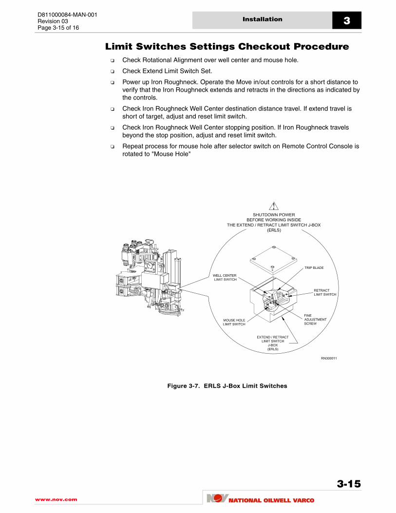
D811000084-MAN-001Revision 03Page 3-15 of 16
Installation 3
Limit Switches Settings Checkout ProcedureCheck Rotational Alignment over well center and mouse hole.
Check Extend Limit Switch Set.
Power up Iron Roughneck. Operate the Move in/out controls for a short distance to verify that the Iron Roughneck extends and retracts in the directions as indicated by the controls.
Check Iron Roughneck Well Center destination distance travel. If extend travel is short of target, adjust and reset limit switch.
Check Iron Roughneck Well Center stopping position. If Iron Roughneck travels beyond the stop position, adjust and reset limit switch.
Repeat process for mouse hole after selector switch on Remote Control Console is rotated to "Mouse Hole"
Figure 3-7. ERLS J-Box Limit Switches
3-15www.nov.com

Installation3D811000084-MAN-001
Revision 03Page 3-16 of 16
This page is intentionally left blank.
www.nov.com
3-16

D811000084-MAN-001Revision 03
Page 4-1 of 28
Operation
Controls And Settings
Control System DescriptionThe Iron Roughneck control system provides the operator with onboard and remotecontrols to operate all of the Iron Roughneck functions. The major components of thecontrol system include:
Remote Control Console (RCC)
Extend / Retract Limit Switch (ERLS)
Torque Setting Panel (TSP)
Hydraulic Enclosure (HE)
The following describe the Iron Roughneck control system's components.
www.nov.com
4-1

Operation4D811000084-MAN-001
Revision 03Page 4-2 of 28
Remote Control Console (RCC)
Figure 4-1. Remote Control Console Panel
3
0
2
1
PRESS TO ROTATE
WELLCENTER
OFF
SPINNER ROTATION
OUT
OPEN
MOUSE
SPINNER
GRIPSPIN
HOLE
IR ROTATE
BOTTOM JAW
CLOSE
IN
E-STOP
MAKEUP TORQUE
IR MOVE
DOWN
XXXXXX
RETARM
BEKA
WRENCHUP
ARMEXT
MAKEUP REPEAT/
SLIPSREL SET
OUTBREAK
START
MAKE UP
NATIONAL OILWELL VARCO
E-Stop
3
0
2
1
PRESS TO ROTATE
WELL
CENTER
OFF
SPINNER ROTATION
OUT
OPEN
MOUSE
SPINNER
GRIP SPIN
HOLEIR ROTATE
BOTTOM JAW
CLOSE
IN
E-STOP
MAKEUP TORQUE
IR MOVE
DOWN
XXXXXX
RETARM
BEKA
WRENCHUP
ARM
EXT
MAKEUP REPEAT/
SLIPS
REL
SET
OUTBREAK
START MAKE UP
NATIONAL OILWELL VARCO
Remote Control Console(RCC)
www.nov.com
4-2

D811000084-MAN-001Revision 03Page 4-3 of 28
Operation 4
Table 4.1 Remote Console Panel Controls
CONTROL RESPONSE
BOTTOM JAW OPEN/CLOSE Rotary Selector Switch
Controls opening and closing of Bottom Jaw of Torque Wrench.
E-STOPPushing in shuts down hydraulic system. Pulling it out allows hydraulic system to restart.
IR MOVE - OUT / IN Rotary Selector Switch
Three-position, return-to-center switch. Causes Iron Roughneck to move in a horizontal direction either toward or away from tubular, as desired.
MAKEUP REPEAT Lamp
Lights red if the pr-set torque has not been reached for completion of the make-up operation. When this happens, the torque process must be repeated.
MAKEUP TORQUE Digital Gauge
Allows operator to monitor the amount of torque being applied by the Torque Wrench. Gauge reading is in Ft - Lbs. Multiply reading by x100 to get actual torque being applied.
MAKEUP/BREAKOUT Rotary Selector Control
Allows operator to control the operation of the Torque Wrenches.
SLIPS-SET-RELEASE VALVE(if equipped)
Sets or releases slips.
SPINNER OFF / GRIP / SPIN Rotary Selector Switch
OFF position causes spinner to open up and disengage from tubular. GRIP causes spinner to close onto tubular. SPIN causes spinner to spin tubular in direction desired, according to chosen selection of SPINNER ROTATION switch (IN/OUT).
SPINNER ROTATION OUT/IN Rotary Selector Switch
Selects direction of rotation of spinner. Spinner will spin in or out when SPINNER switch is placed in SPIN position.
WRENCH - UP / DOWN Rotary Selector Switch
Sends Torque Wrench up or down to level desired.
4-3www.nov.com

Operation4D811000084-MAN-001
Revision 03Page 4-4 of 28
Remote Control Console Start-up ProcedureBefore applying power to the Iron Roughneck remote control console (RCC), perform athrough inspection of the equipment. There is no need to set or adjust any control insideRCC cabinet.
1. If the IR Remote Control Console (RCC) has been taken out of active service (i.e. shut down and de-energized) the following start-up procedure shall be used and performed by a qualified electrician.
2. Megger test the power cable if the console has been disconnected, or upon first installation.
3. Ensure that the correct voltage and frequency is supplied from the distribution board before the main switch is turned on in the console. This should be 24 VDC.
4. Make sure that no emergency stops (red mushroom buttons) are activated. If the emergency stops have been activated, deactivate the emergency stops by turning one-quarter turn counter clockwise and pulling out. There is one located on the RCC. Others may be located elsewhere in the system depending on the exact setup for a particular rig.
5. Test the function of the emergency stop circuits for the IR. If the emergency stops work correctly, deactivate, as described in step 6 below, and go to step 7.
6. After emergency shutoff, the operator should reset all controls to the normal Start position an check for any hydraulic or electrical problems before pulling out the E-Stop button a restarting the operation.
7. Ensure that all circuits are operational before starting any other testing. If not all circuits are operational, only qualified control system personnel should operate the IR.
Refer to "Long Term Storage of Iron Roughneck Equipment" in the Maintenance section ofthis manual for information regarding storage and storage removal procedures of IronRoughneck electrical equipment.
To avoid possible personnel injury of equipmentdamage, make sure the IR operational area is clear ofpersonnel and equipment during startup.
www.nov.com
4-4

D811000084-MAN-001Revision 03Page 4-5 of 28
Operation 4
Limit Switch J-BoxExtend / Retract Limit Switch J-Box
An ERLS (Extend / Retract Limit Switch) J-box (see Figure 4.2) mounted on the structuralsection of the Iron Roughneck controls extend and retract travel limits. Selecting eitherMOUSEHOLE or WELL CENTER position affects the horizontal distance traveled by theAutomated Arm.
Figure 4-2. Extend / Retract Limit Switch J-Box
!Shutdown power before working inside of extend / retractlimit switch (ERLS) J-Box. Failure to observe thisprecaution can cause serious injury and / or damage to theequipment.
4-5www.nov.com

Operation4D811000084-MAN-001
Revision 03Page 4-6 of 28
Setting Extend / Retract Limit Switch J-Box
Unless stated otherwise, all adjustments mentioned below are found on the Extend /Retract Limit Switch (ERLS) J-Box (see Figure 4.2).
1. Position Roughneck precisely over Well Center; shutdown power.
2. Open ERLS J-Box; four thumbscrews on cover.
3. Loosen screws on limit switch and fine adjustment brackets.
4. Slide switch until plunger contacts trip blade and retracts approximately 1/8", tighten screws on brackets, and replace cover.
5. Rotate selector switch on Remote Control Console (RCC) to "WELL CENTER".
6. Power up Roughneck, extend and retract Roughneck with Remote Control Console.
7. If Roughneck is traveling short of Well Center, Move the switch farther from the trip blade (towards back of machine) using the fine adjustment screws.
8. If Roughneck is traveling beyond Well Center, move the switch closer to the trip blade (towards front of machine) using the fine adjustment screws.
9. Repeat process for Mouse Hole after selector switch is rotated to "MOUSEHOLE".
10. Tighten screws on ERLS J-Box.
iiOnce the position (MOUSEHOLE or WELL CENTER) isselected on the Remote Control Console (RCC), theoperator must remove a locking pin at the base of the IronRoughneck (see Figure 4.5), and manually rotate the IronRoughneck Automated Arm to the left or right, asappropriate, to align with either the Mousehole or the WellCenter. The Operator can then extend the Arm to thechosen position.
www.nov.com
4-6

D811000084-MAN-001Revision 03Page 4-7 of 28
Operation 4
Figure 4-3. Typical Iron Roughneck, Retracted/Park Postion
Figure 4-4. Typical Iron Roughneck, Extended Position
RN300005
Drill Floor
Drill Floor
RN300006
4-7www.nov.com

Operation4D811000084-MAN-001
Revision 03Page 4-8 of 28
Positioning the Iron Roughneck for Operation1. Choose either well center or mousehole as the destination for the Iron Roughneck,
as appropriate, using the Well Center/Mouse Hole selector switch located on the Iron Roughneck Remote Control Console (RCC).
2. Loosen nut on the rotation ring at the base of Iron Roughneck and insert locking pin through stop ring and base. Push Iron Roughneck into alignment with either the mousehole or well center, as required.
3. Extend and position Iron Roughneck over Well Center or Mouse Hole; once the roughneck is in proper position, tighten rotation ring lock nut (see Figure 4.5).
4. If Iron roughneck travels long or short see "Setting the Extend/Retract Limit Switch (ERLS) J-Box".
Figure 4-5. Rotation Stop Ring
www.nov.com
4-8

D811000084-MAN-001Revision 03Page 4-9 of 28
Operation 4
Torque Setting Panel
Figure 4-6. Setting Panel Control
Table 4.2 Torque Setting Panel Controls
CONTROL RESPONSE
Torque Setting Control Used to set maximum makeup torque.
JAW Pressure GaugeIndicates hydraulic pressure in the Upper and Lower Torque Wrench jaw.
Torque GaugeIndicates the amount of torque the system is providing during makeup operation.
System Pressure GaugeIndicates hydraulic pressure available within the Iron Roughneck.
E-STOPCauses hydraulic system to shut down immediately after this control is pressed.
4-9www.nov.com

Operation4D811000084-MAN-001
Revision 03Page 4-10 of 28
Adjusting the Makeup Torque
The makeup torque must be set before performing makeup or breakout of drill pipe/drillcollars.
1. Ensure the Hydraulic Power Unit is running correctly and the full pressure of 3000 psi is available according to the System Gauge on the Torque Setting Panel.
2. Adjust Torque Setting Control Valve (see Figure 4.6) for Makeup Torque (Counter Clockwise for decrease torque setting and Clockwise for increase torque setting).
3. To Set Makeup torque, actuate the Torque Control Valve (as if performing a makeup sequence) and hold, while turning the Torque Setting Control knob. Turn the Torque Setting Control knob while watching the Torque Gauge until the desired torque is achieved.
4. Release the Torque Control Valve and lock the Torque Setting Control knob using the locking nut found just behind the knob.
5. Check the torque setting by shifting the Torque Control Valve (pull the Torque Control Valve out and hold). The Torque Setting Gauge will indicate current torque setting.
Make-Up Torque is now set for the Top Wrench.
www.nov.com
4-10

D811000084-MAN-001Revision 03Page 4-11 of 28
Operation 4
Adjusting the Jaw Pressure
The pressure for the Top Jaw and the Lower Jaw must be set before adjusting torque orperforming makeup or breakout functions. The Jaw pressure desired will vary according tothe size of the tubular being handled.
1. Ensure the Hydraulic Power Unit is running correctly and the full pressure of 3000 psi is available according to the System Gauge on the Torque Setting Panel.
2. In the Hydraulic Enclosure, choose either the TOP JAW Valve or the BOTTOM JAW Valve, as desired and actuate, as in closing the jaw.
3. If maximum jaw pressure is desired, close the Ball Valve mounted in the Hydraulic Enclosure. This bypasses the Downstream Relief Valve and allows the full 3000 psi pressure to flow to the jaws.
4. If regulated jaw pressure is desired, open the Ball Valve. This allows the Downstream Relief Valve to function.
5. While observing the Jaw Pressure Gauge on the Torque Setting Panel, turn the adjustment stem on the Downstream Relief Valve until the Jaw Pressure Gauge reads the desired pressure.
Jaw pressure for the Top and Bottom Jaws is now set.
Ensure the correct jaw pressure is chosen for the sizeof tubular being handled. Excessive jaw pressure candamage a tubular.
Exercise extreme caution when performingadjustments on the hydraulic system. Fluid escapingunder pressure can easily cause serious injury ordeath to personnel and / or damage to the equipment.
4-11www.nov.com

Operation4D811000084-MAN-001
Revision 03Page 4-12 of 28
Hydraulic Enclosure
Figure 4-7. Hydraulic Enclosure Controls Details
www.nov.com
4-12

D811000084-MAN-001Revision 03Page 4-13 of 28
Operation 4
Table 4.3 Hydraulic Enclosure Controls
CONTROL RESPONSE
BOTTOM JAW VALVE(Valve No. 5)
Hydraulic manual valve to clamp and unclamp the bottom jaws on a drill pipe connection.
IR Rotate(if equipped)
Roates tool clockwise or counter clockwise.
MOVE IN-OUT VALVE(Valve No. 8)
Hydraulic manual valve to extend and retract to and from well center or mousehole.
SLIPS-SET-RELEASE VALVE(if equipped)
Sets or releases slips.
SPINNER GRIP VALVE(Valve No. 6)
Hydraulic manual valve to engages and disengages the spinner grips onto tubular.
SPINNER ROTATION VALVE(Valve No.7)
Hydraulic manual valve to select spin rotation in or out.
TOP JAW VALVE(Valve No. 4)
Hydraulic manual valve to clamp and unclamp the top jaws on a drill pipe connection.
TORQUE VALVE(Valve No. 2)
Hydraulic manual valve to make or break a connection.
WRENCH LIFT VALVE(Valve No. 3)
Hydraulic manual valve to adjust the wrench assembly vertical height.
4-13www.nov.com

Operation4D811000084-MAN-001
Revision 03Page 4-14 of 28
Hydraulic Rotation Column AssemblyThe following procedure shows how to position the hydraulic rotation column assembly tothe well center or to the mousehole position.
1. Ensure that the 2-way, manually-operated directional valve (DAAM-1) on the rotation manifold is in the UNLOCK position for normal connection operation. To shift the valve, twist the knob to the detented position as labelled on the knob. Twist Counter-clockwise to lock and clockwise to unlock.
2. Ensure that the 2-way 2-position DAMM-2 valve on the rotation manifold is in the LOCK position for normal connection operation. To shift the valve twist the knob to the detented position as labelled on the knob. Twist Counter-clockwise to lock and clockwise to unlock.
3. Choose either well center or mousehole as the destination for the Iron Roughneck, as appropriate, using the Well Center/Mouse Hole selector switch located on the Iron Roughneck Remote Control Console (RCC).
4. Shift the IR rotate selector switch on remote control console to rotate Iron Roughneck into alignment with either the mousehole or well center, as required.
5. If Iron roughneck rotates past or rotates short of the rotation targets see "Setting the Rotation Target Switches" in this section.
6. Extend and position Iron Roughneck tools over Well Center or Mouse Hole; once the roughneck is in proper target position,
7. If Iron roughneck tools travels long or short see "Setting the Extend/Retract Limit Switch (ERLS) J-Box" in the "General Operating Procedures" section of this manual
www.nov.com
4-14

D811000084-MAN-001Revision 03Page 4-15 of 28
Operation 4
Rotate Column Assembly
Setting the Rotation Target Switches
The rotation target sensors are used for rotation index positioning to position the IronRoughneck to the well center or to the mousehole locations. The rotation sensorcomponents consist of a rotation target switch and a magnetic rotation target.
To adjust the rotation target switch and target:
1. Remove the screws and lock washers from the rotation target and remove the rotation targets from their mounting surface on the column base upper plate.
2. Rotate the column to the direction of the first index point position (well center). Since the proximity position points of rotation need to be first set up estimate the stop location and extended the tools to reach and center up to the location position by toggling the Iron Roughen to the correct orientation. Once the reach and rotation of the tools are center proceed to set rotation target switches.
3. Select the nearest mounting target location on the column base upper plate, and install the first rotation target. Install the target so that the target is mounted within proximity range below fist target switch.
4. Make sure the rotation target is lined up with the target switch sensor.
5. Loosen the clamp holding the target switch sensor.
6. Adjust the first target switch sensor by sliding it up or down to achieve a gap of 1/8" between the target switch sensor and the rotation target.
7. Tighten the clamp holding the target switch sensor.
8. To adjust the column's second index point position (mousehole) repeat steps 2 - 7.
9. Repeat the adjustments as necessary.
10. Verify the rotation operation. Ensure that the column rotates and stops at target position settings (well center and mousehole positions).
!Do not rotate the column more than what the IronRoughneck will allow with service loops connected.Otherwise, kinking of the service loops can causepremature failure and/or damage to the equipment.
4-15www.nov.com

Operation4D811000084-MAN-001
Revision 03Page 4-16 of 28
Rotation Manual Override The Iron Roughneck rotation column assembly is equipped with a manual override to allowrotation operations to be controlled locally at rotation manifold (see Figure 4.8). In theevent of a power down of the Iron Roughneck, or if a failure has occurred preventing theremote controlled hydraulic rotation system from being operated from the remote controlconsole location, follow the manual rotation override instructions to manually rotate theIron Roughneck to or away from the index rotation set position.
Figure 4-8. Rotation Manifold Valve Assembly
www.nov.com
4-16

D811000084-MAN-001Revision 03Page 4-17 of 28
Operation 4
Rotation Manifold Override SystemThe following procedure shows how to position the hydraulic rotation column assembly tothe well center or to the mousehole alignment positions manually.
1. Ensure that the 2-way, manually-operated directional valve (DAAM-1) on the rotation manifold is in the LOCK position for manual override operations. To shift the valve twist the knob to the detented position as labelled on the knob. Twist Counter-clockwise to lock and clockwise to unlock.
2. Ensure that the 2-way manually-operated directional valve (DAMM-2) on the rotation manifold is in the UNLOCK position for manual override operation. To shift the valve twist the knob to the detented position as labelled on the knob. Twist Counter-clockwise to lock and clockwise to unlock.
3. To manually pressurize the rotation circuit slowly push the hand pump handle downwards. This will release and hold the brake off only.
4. Then manually push the Iron Roughneck into alignment to either the mousehole or well center, as required.
5. When override operations have been completed. Return the 2-way manually operated directional valves to the normal operation position. Twist Counter-clockwise to lock and clockwise to unlock.
4-17www.nov.com
Operation4D811000084-MAN-001
Revision 03Page 4-18 of 28
Makeup and Breakout OperationsThis section explains basic Iron roughneck operating procedures. The primary function ofthe Iron Roughneck is to makeup and breakout drill string connections.
Start-Up Procedures1. Prior to field start-up operation, check over the Iron Roughneck assemblies,
Hydraulic power unit and controls, to assure all components are included and in a serviceable condition. Refer to the "Set-up and Installation" section for Installation and check out procedures.
2. Provide all electrical connections from SCR to HPU to Remote Control Console and from Remote Control Console to Roughneck.
3. Provide hydraulic pressure in accordance with the instructions provided for your unit.
4. Check the "SYSTEM" pressure gauge on the Torque Setting Panel should indicate 3000 psi.
5. Check the pressure set for the Top Jaw and the Lower Jaw. The top jaw and lower jaw pressures must be set before adjusting torque or performing makeup or breakout functions. Refer to "Adjusting the Jaw Pressure" section for jaw pressure setting instructions.
6. Check the Make up and breakout torque set. The makeup and breakout torque must be set using the Torque Setting Panel. Refer to "Adjusting the Makeup Torque" section for makeup torque setting instructions.
!The IR3080 is not to be used as a backup or substitute forthe top drive. The IR3080 is designed for a specificpurpose. Using it for other than its intended purpose maycause personnel injury or damage to equipment.
www.nov.com
4-18

D811000084-MAN-001Revision 03Page 4-19 of 28
Operation 4
Making Connections
Makeup Initial PositionEnsure the following parts of the Iron Roughneck are in the indicated positions prior tonormal makeup operation:
Drill pipe pin should be in box end of drill pipe.
The SYSTEM PRESSURE gauge should indicate 3000 PSI.
Iron Roughneck in Park/Standby position (Automated Arm assembly is retracted).
Either Well Center or Mousehole, as required, is chosen on the Well Center / Mouse Hole selector switch, and extend / retract limit switches adjusted and the Iron Roughneck lined up with the chosen destination.
Rotational Locking Pin inserted and Rotation Ring and Locking Nut set.
The SPINNER selector switch is in the "OFF" position.
The SPINNER ROTATION selector switch is set to the "IN" position.
Makeup torque is pre-set on Torque Setting Panel.
The Makeup/Breakout selector switch is in the "START" position or position "0".
The BOTTOM JAW selector switch is in the "OPEN" position.
Figure 4-9. IR30120 Top and Bottom intensifier Valves (IR30120 only)
ii For IR30120 models, the INTENSIFIER VALVES must beopen for makeup torque values greater than 60,000 ft-lbs;and closed for torque values equal to or less.
Top WrenchIntensifier Valve(Shown in CLOSED position)
Bottom WrenchIntensifier Valve(Shown in CLOSED position)
RN300100
4-19www.nov.com

Operation4D811000084-MAN-001
Revision 03Page 4-20 of 28
Figure 4-10. Remote Control Console, Making Connections
www.nov.com
4-20

D811000084-MAN-001Revision 03Page 4-21 of 28
Operation 4
Normal Makeup ProcedureUnless stated otherwise, all controls mentioned below are those found on the RemoteControl Console (RCC) see Figure 4.10.
1. Choose either well center or mousehole as the destination for the Iron Roughneck, as appropriate, using the Well Center/Mouse Hole selector switch located on the Iron Roughneck Remote Control Console (RCC).
2. Starting with the IRON ROUGHNECK in the Makeup Initial Position (see Figure 4.10), with the Torque Wrench jaws open, several feet from the drill pipe/drill collar, select the IR MOVE IN / OUT switch and choose position OUT. Completely extend the Iron Roughneck to the chosen out position (extend position), see Figure 4.10.
3. If necessary, adjust the vertical height of the Iron Roughneck by operating the WRENCH UP or DOWN control. Place the center of the top and bottom jaws at the correct pipe joint connection position.
4. Rotate the "BOTTOM JAW" rotary selector switch to CLOSE position. The bottom jaws will close around the drill pipe tool joint.
iiHold the IR MOVE IN /OUT (extend/retract) switch until theIron Roughneck comes to the preset stop as set by theERLS box. Do not prematurely release the switch. Allowthe Iron Roughneck to travel to its designated stoppingposition. The IR MOVE IN/OUT function (extend/retract)will not work if Bottom wrench, Top wrench or Spinner isclosed.
!Ensure that the BOTTOM JAW of the torque wrench isengaged to the drill pipe/drill collars before rotating thespinner or the Top Jaw of the torque wrench. Failure toobserve this precaution can cause serious injury and / ordamage to the equipment.
4-21www.nov.com

Operation4D811000084-MAN-001
Revision 03Page 4-22 of 28
5. Rotate the SPINNER ROTATION rotary selector switch to position "IN".
6. Turn the SPINNER rotary selector switch to position "SPIN". The spinner rollers will grip, and after a brief delay, the spinner will begin to spin in the drill pipe.
7. When the drill pipe is spun in, rotate SPINNER switch to the "OFF" position. The spinner rollers will stop rotating and the spinner will release.
8. Once the drill pipe has been spun in, rotate the Makeup/Breakout selector switch clockwise from position "0" to position "1". The top wrench will rotate to a starting position for makeup. (Green Indicator should be on)
9. Rotate the Makeup/Breakout selector switch clockwise to position "2". The top jaw will close.
10. Rotate the Makeup/Breakout selector switch clockwise to position "3". The top wrench will rotate right ("make up"). Rotation will stop when the set torque is reached or when the wrench reaches end of stroke. The red MAKEUP REPEAT light will come on if torque is not reached by the end of the Top Wrench stroke. If the wrench reaches its end of stroke before the set torque is reached, repeat steps 8-11. If the set torque is reached, the green MAKEUP COMPLETE light remains green.
11. Rotate the Makeup / Breakout selector switch to position "0". The top wrench will open and return to the start position.
12. Rotate the BOTTOM JAW switch to the "OPEN" position. The bottom jaw will open.
13. Rotate the IR MOVE selector switch to the "IN" position. The Iron Roughneck will move away from the drill pipe/drill collar to the parking position. Place the Iron Roughneck in position for next use, or turn off system, as required.
iiMakeup sequences will be controlled by rotation ofMakeup / Breakout Selector switch in a CLOCKWISEdirection.
iiIf MAKEUP COMPLETE light (green light) remainsilluminated, no further makeup is required. If MAKEUPREPEAT light (red light) illuminates, repeat steps 8-11.
iiThe IR MOVE OUT function (extend) will not work ifBottom wrench, Top wrench or Spinner is closed.
www.nov.com
4-22

D811000084-MAN-001Revision 03Page 4-23 of 28
Operation 4
Breaking Connections
Breakout Initial PositionEnsure the following parts of the IRON ROUGHNECK are in the indicated positions priorto normal breakout operation (Breaking Connections):
The top drill pipe and bottom drill pipe are connected.
The SYSTEM PRESSURE gauge should indicate 3000 PSI.
Iron Roughneck in Park/Standby position (Automated Arm assembly is retracted).
Either Well Center or Mousehole, as required, is chosen on the Well Center / Mouse Hole selector switch, and extend / retract limit switches adjusted and the IRON ROUGHNECK lined up with the chosen destination.
Rotational Locking Pin inserted and Rotation Ring and Locking Nut set.
The spinner selector switch is set to the "OFF" position.
The SPINNER ROTATION selector switch is set in the "OUT" position.
The Makeup/Breakout selector switch is in the "START" position or position "0".
The BOTTOM JAW selector switch is in the "OPEN" position.
.
Figure 4-11. IR30120 Top and Bottom intensifier Valves (IR30120 only)
iiFor IR30120 models, the INTENSIFIER VALVES must beopen for makeup torque values greather than 80,000 ft-lbs;and closed for torque values equal to or less.
Top WrenchIntensifier Valve(Shown in CLOSED position)
Bottom WrenchIntensifier Valve(Shown in CLOSED position)
RN300100
4-23www.nov.com

Operation4D811000084-MAN-001
Revision 03Page 4-24 of 28
Figure 4-12. Remote Control Console, Breaking Connections
www.nov.com
4-24
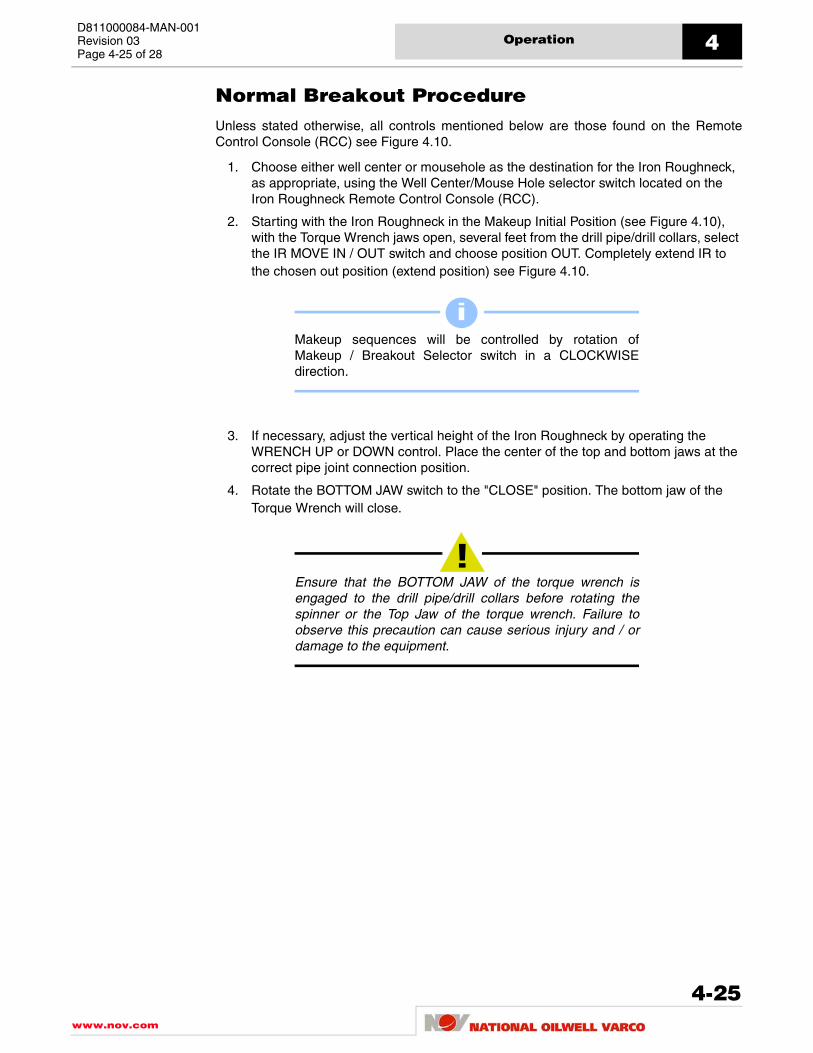
D811000084-MAN-001Revision 03Page 4-25 of 28
Operation 4
Normal Breakout ProcedureUnless stated otherwise, all controls mentioned below are those found on the RemoteControl Console (RCC) see Figure 4.10.
1. Choose either well center or mousehole as the destination for the Iron Roughneck, as appropriate, using the Well Center/Mouse Hole selector switch located on the Iron Roughneck Remote Control Console (RCC).
2. Starting with the Iron Roughneck in the Makeup Initial Position (see Figure 4.10), with the Torque Wrench jaws open, several feet from the drill pipe/drill collars, select the IR MOVE IN / OUT switch and choose position OUT. Completely extend IR to the chosen out position (extend position) see Figure 4.10.
3. If necessary, adjust the vertical height of the Iron Roughneck by operating the WRENCH UP or DOWN control. Place the center of the top and bottom jaws at the correct pipe joint connection position.
4. Rotate the BOTTOM JAW switch to the "CLOSE" position. The bottom jaw of the Torque Wrench will close.
iiMakeup sequences will be controlled by rotation ofMakeup / Breakout Selector switch in a CLOCKWISEdirection.
!Ensure that the BOTTOM JAW of the torque wrench isengaged to the drill pipe/drill collars before rotating thespinner or the Top Jaw of the torque wrench. Failure toobserve this precaution can cause serious injury and / ordamage to the equipment.
4-25www.nov.com

Operation4D811000084-MAN-001
Revision 03Page 4-26 of 28
5. Rotate the Makeup/Breakout selector switch counter-clockwise from position "0" to position "3". The top jaw will close.
6. Rotate the Makeup/Breakout Selector switch to position "2". The top wrench will rotate left - breakout. Rotation will stop when wrench reaches end of stroke.
7. Rotate the Makeup/Breakout Selector switch button to position "1". The top jaw will open.
8. Rotate the Makeup/Breakout Selector switch to position "0". The top wrench will turn right to the start position.
9. Rotate the SPINNER ROTATION rotary selector switch to position "OUT".
10. Turn the SPINNER Rotary Selector Switch to position SPIN. Spinner rollers will grip, and the rollers will start spinning the pipe. If spinner cannot spin pipe, open spinner grip and repeat steps 5-8.
11. When pipe is spun out, rotate SPINNER Rotary Selector switch to OFF position. Spinner will stop rotation and spinner rollers will release.
12. Rotate BOTTOM JAW switch to OPEN position. Bottom jaw will open.
13. Rotate the IR MOVE Selector switch to "IN". The Iron Roughneck will move to the parking position. Place the Iron Roughneck in position for next use, or turn off system, as required
iiBreakout sequences will be controlled by rotation ofMakeup / Breakout Selector switch in a COUNTERCLOCKWISE direction.
iiThe IR MOVE IN function (retract) will not work if Bottomwrench, Top wrench or Spinner is closed.
www.nov.com
4-26

D811000084-MAN-001Revision 03Page 4-27 of 28
Operation 4
Emergency Stop ProceduresIf problems occur during operation, the operator can press the E-STOP button on theRCC. This will shut off electrical power to the remote control console and/or the hydraulicsystem (if the hydraulic power unit is wired in series with the Iron Roughneck controls).
Start after Emergency StopAfter emergency shutoff, the operator should reset all controls to the normal Start positionan check for any hydraulic or electrical problems before pulling out the E-Stop button arestarting the operation.
4-27www.nov.com

Operation4D811000084-MAN-001
Revision 03Page 4-28 of 28
This page is intentionally left blank.
www.nov.com
4-28

D811000084-MAN-001Revision 03
Page 5-1 of 34
Maintenance
Preventive Maintenance
General Preventive MaintenanceAppropriate and correct service methods and repair procedures are essential for thereliable operation oft the Iron Roughneck and related equipment, and especially for thesafety of the crew. This manual provides general directions for the Iron Roughneckoperations and for service and repair work.
All maintenance should be performed from a routine maintenance schedule that providesa checklist of items and / or procedures to be followed and a time frame or frequencyinterval that these tasks are to be performed. Simple checklists or series of checklists canbe prepared for maintenance personnel. The Preventive / Periodic Maintenance Table onthe following page presents such a routine schedule.
This manual cannot anticipate all possible variations in techniques, tool, parts, and in theskill level of individuals operation or maintaining the Iron Roughneck. This manual cannotprovide advice, cautions, or warnings for every potential situation. Accordingly, you mustfirst establish that you will not comprise crew safety or the integrity of the equipment byyour choice of methods, tools, or parts.
Individual circumstances may dictate changes to the suggested maintenance intervals.Maintenance time frames may be different for a rig operating in blowing sand, offshore, orin an arctic setting. Other factors to consider include actual run time, how hard themachine is being worked, and any other factors that would require more frequentmaintenance. Careful consideration and a tendency to do a little more than the minimummaintenance are keys to reaping the benefits of a regular maintenance program.
Reference all applicable OEM literature sections for additional detailed maintenanceinformation on individual components and assemblies.
Before performing maintenance on, or disconnecting any high-pressure flanges, piping,hoses or vessels, ensure the unit has been bled to "zero" pressure. Shut down, isolate,and tag the system controls as "Out of Service" so that others cannot pressurize thesystem during maintenance or repairs. Always consider possible sources of trappedpressure. Observe similar procedures for electrical connections, ensuring the system islocked out before attempting any maintenance.
Open all hydraulic lines carefully. Make sure that the drainage oil is caught in a bucket so itdoes not spill on the floor or over the machine. Cover fittings and plugs with a rag and thenunscrew slowly.
www.nov.com
5-1

Maintenance5D811000084-MAN-001
Revision 03Page 5-2 of 34
Preventive MaintenanceFollowing these rules will prevent an accident even if the mistake of opening a line underpressure has been made, since there is a chance to re-tighten the fittings. Furthermore,the oil will be caught on the rag and not leak onto the machine or floor.
Sometimes the tubing will stick in the fitting even after the retainer nut is completely unscrewed. Slightly tap the tubing or plug to ensure it is loose. Oil should then slowly begin to run out of the break.
Replace all tubing, hoses, fittings, and other parts with pieces of identical size and material, since the hoses and seals for some types of fire-resistant fluids are not interchangeable with those for petroleum fluids, and vice-versa.
In restarting the system, turn the pump over slowly by starting and stopping the electric motor a number of times. If all piping connections are not secure, leaks will show up. Furthermore, if a mistake in piping or valving has been made, the action of the machine may be slow enough not to cause any damage. Always check out the function of the machine before putting the machine to work.
Always keep oil leaks cleaned up. Tighten or replace all leaky fittings and gaskets.
Keep body away from direct contact with hoses, fittings, and hydraulic devices when a piece of equipment is running. Bursting pipes can be dangerous. Oil escaping through a very small hole can penetrate the skin if close contact is made.
Some individuals are allergic to hydraulic fluids, so reasonable care should be taken to avoid or limit contact with bare skin and, especially, the eyes.
Never attempt to increase the output of a piece of equipment by adjusting the valving beyond its rated capacity, pressure rating, or strength.
www.nov.com
5-2

D811000084-MAN-001Revision 03Page 5-3 of 34
Maintenance 5
Preventive / Periodic Maintenance
Table 5.1 Iron Roughneck Preventive / Periodic Maintenance
IRON ROUGHNECK
MAINTENANCE PROCEDURE SCHEDULE
Inspect equipment during operation, noting any abnormal sounds or vibrations.
DAILY
Investigate any fluid leaks and take action as necessary. DAILY
Apply grease to all Zerk fittings per grease schedule chart, Figure 5.1. WEEKLY
Visually inspect pipe spinner rollers. Verify that they are still within their wear limit.
DAILY
Table 5.2 Hydraulic Systems Preventive / Periodic Maintenance
HYDRAULIC SYSTEMS
MAINTENANCE PROCEDURES SCHEDULE
Monitor gauges for correct pressure. DAILY
Check all filters and / or screens. DAILY
Remove all water and / or foreign material, and replace fluid as necessary. DAILY
Check all lines and connections for any leaks, and repair as necessary. DAILY
Observe equipment during operation, noting any abnormal sounds or vibrations. Adjust if necessary.
WEEKLY
Inspect main hydraulic reservoir for any indication of contamination. Clean and renew as needed.
WEEKLY
Clean and flush all system filters, screens and traps. WEEKLY
Inspect and clean all connections and lines. WEEKLY
Replace system hydraulic fluid. YEARLY
Check, recalibrate and pressure test all system lines and instrumentation. YEARLY
Clean, adjust, and / or replace any components necessary. YEARLY
5-3www.nov.com

Maintenance5D811000084-MAN-001
Revision 03Page 5-4 of 34
Table 5.3 Hydraulic Systems Preventive / Periodic Maintenance
ELECTRICAL SYSTEM
MAINTENANCE PROCEDURE SCHEDULE
If calibration is needed for any aspect of the Iron Roughneck, Contact National Oilwell.
6 MONTHS
Clean, adjust and / or replace any components necessary. 6 MONTHS
www.nov.com
5-4

D811000084-MAN-001Revision 03Page 5-5 of 34
Maintenance 5
Lubrication and Inspection
Lubrication ScheduleFor Lubrication and Hydraulic Fluid Specifications, refer to the "Recommended Lubricantsand Fluids" section located in Maintenance section in this manual.
Figure 5-1. Typical Arm Mounted Iron Roughneck Lubrication Grease Points
NTHLY
removetop and bottom clamp rings
to access grease pionts4 places
h side
1 MONTH
WEEKLY
each side
WEEKLYeach side
WEEKLY
each side
WEEKLY
each side
3 MONTHSbrush surface undercylinders with grease
2 each side
each sideWEEKLY
RN 300013
betweWE
each side
WEEKLY
WEEKLY
each side
WEEKLY
each side
3 MONTH
between rollers/4 places
WEEKLY
each side
1 MONTH
remove top and bottom clamp rings / 4 places
MONTHLY
each side
WEEKLY
each side
WEEKLY
between rollers/4 places
5-5www.nov.com

Maintenance5D811000084-MAN-001
Revision 03Page 5-6 of 34
Wrench Lubrication
Always clean grease fittings before pumping grease to help prevent contaminants fromentering the system and to increase the life of the components.
Table 5.4 Wrench Lubrication Schedule
CHECK POINT PROCEDURE LUBRICATION SCHEDULE
1Grease cylinder pin fittings with 1 - 3 strokes of a hand-operated grease gun.
NLGI Multipurpose Grease DAILY
2Brush all moving surfaces parts with grease.
NLGI Multipurpose Grease WEEKLY
!All equipment should be shut down, isolated and tagged"OUT OF SERVICE" before any maintenance procedure isperformed. Any unexpected start-up of equipment duringprocedure can cause serious injury or death to personneland / or damage to the equipment.
www.nov.com
5-6

D811000084-MAN-001Revision 03Page 5-7 of 34
Maintenance 5
Column-Guide-Arm Lubrication
Always clean grease nipples before pumping grease to help prevent contaminants fromentering the system and to increase the life of the components.
Figure 5-2. Lubrication Points and Inspection Points
5-7www.nov.com

Maintenance5D811000084-MAN-001
Revision 03Page 5-8 of 34
Table 5.5 Column-Guide-Arm Lubrication Schedule
CHECK POINT PROCEDURE LUBRICATION SCHEDULE
3
Grease all linkage pin fittings.(1 fitting/linkage pin each side) with1 - 3 strikes of a hand-operated grease gun.
NLGI Multipurpose Grease DAILY
4
Grease all cylinder pin fittings.(1 fitting/cylinder pin each side) with1 - 3 strokes of a hand-operated grease gun.
NLGI Multipurpose Grease DAILY
5
Grease all vertical track cam followers.(1-fitting/ cam follower 2 each side) with 1 - 3 strokes of a hand-operated grease gun.
NLGI Multipurpose Grease WEEKLY
6
Grease the Rotating Bearing on the Vertical Track Assembly. Apply several strokes of grease to the fittings, rotate the Vertical Track Assembly, and apply several more strokes. Repeat pumping grease and rotating the Vertical Track Vertical Track Assembly to distribute the grease until grease is visible around the top of the rotating bearing seal.
Note: Remove top and bottom clamp rings to access grease points.
NLGI Multipurpose Grease WEEKLY
!All equipment should be shut down, isolated and tagged"OUT OF SERVICE" before any maintenance procedure isperformed. Any unexpected start-up of equipment duringprocedure can cause serious injury or death to personneland / or damage to the equipment.
www.nov.com
5-8

D811000084-MAN-001Revision 03Page 5-9 of 34
Maintenance 5
Automated Arm Lubrication
For Lubrication and Hydraulic Fluid Specifications, refer to the "Recommended Lubricants and Fluids" section located in Maintenance section in this manual. Always clean grease nipples before pumping grease to help prevent contaminants from entering the system and to increase the life of the components.
Table 5.6 Automated Arm Lubrication Schedule
CHECK POINT PROCEDURE LUBRICATION SCHEDULE
7
Grease all linkage pin fittings.(1 fitting/linkage pin each side) with 1 - 3 strikes of a hand-operated grease gun.
NLGI Multipurpose Grease DAILY
8
Grease all cylinder pin fittings.(1 fitting/cylinder pin each side) with 1 - 3 strokes of a hand-operated grease gun.
NLGI Multipurpose Grease DAILY
9
Grease all vertical track cam followers.(1-fitting/ cam follower 2 each side) with 1 - 3 strokes of a hand-operated grease gun.
NLGI Multipurpose Grease MONTHLY
10
Grease the Rotating Bearing on the Vertical Track Assembly. Apply several strokes of grease to the fittings, rotate the Vertical Track Assembly, and apply several more strokes. Repeat pumping grease and rotating the Vertical Track Vertical Track Assembly to distribute the grease until grease is visible around the top of the rotating bearing seal.
Note: Remove top and bottom clamp rings to access grease points.
NLGI Multipurpose Grease MONTHLY
!All equipment should be shut down, isolated and tagged"OUT OF SERVICE" before any maintenance procedure isperformed. Any unexpected start-up of equipment duringprocedure can cause serious injury or death to personneland / or damage to the equipment.
5-9www.nov.com

Maintenance5D811000084-MAN-001
Revision 03Page 5-10 of 34
Inspection SchedulePerform Inspection at scheduled intervals as noted in inspection table.
Wrench InspectionTable 5.7 Wrench Inspection Schedule
CHECK POINT PROCEDURE SCHEDULE
1 Visually inspect Jaw Dies. DAILY
2
Flush out any drill mud, which may accumulate around the jaw dies or under the jaw cylinders, and in between the top jaw and bottom jaw assemblies. Use wire brush as needed to keep jaw dies clean of metal shavings.
DAILY
3 Check all hose and fitting for hydraulic oil leakage. DAILY
4Visually inspect for loose or missing retention hardware. Make sure that all bolts, washers, and hex nuts are secured and secondary locking device intact.
WEEKLY
5 Visually inspect that all pins and cotter pins are secured, and intact. WEEKLY
6Inspect all hoses, fittings thoroughly for any evidence of chaffing or hydraulic oil leakage. Replace if necessary.
MONTHLY
7Inspect hydraulic cylinder thoroughly for hydraulic oil leakage or damage, Repair or replace if necessary.
6 MONTHS
iiInspect jaw dies frequently and replace if worn ordamaged.
!Keep hands clear of Jaw Dies while dies are extending.
!Maintain the original security devises, such as; safety wire,cotter pins lock nuts, retaining rings, loctite, ect. To preventparts from vibrating loose and falling.
www.nov.com
5-10

D811000084-MAN-001Revision 03Page 5-11 of 34
Maintenance 5
!All equipment should be shut down, isolated and tagged"OUT OF SERVICE" before any maintenance procedure isperformed. Any unexpected start-up of equipment duringprocedure can cause serious injury or death to personneland / or damage to the equipment.
5-11www.nov.com

Maintenance5D811000084-MAN-001
Revision 03Page 5-12 of 34
Column-Guide-Arm InspectionTable 5.8 Column-Guide-Arm Inspection Schedule
CHECK POINT PROCEDURE SCHEDULE
8 Check all hose and fitting for hydraulic oil leakage. DAILY
9Check the inline hydraulic filter. Replace as necessary if the indicator indicates is red.
DAILY
10Visually inspect for loose or missing retention hardware. Make sure that all bolts, washers, and hex nuts are secured and secondary locking device intact.
WEEKLY
11 Visually inspect that all pins and cotter pins are secured, and intact. WEEKLY
12Inspect all hoses, fittings thoroughly for any evidence of chaffing or hydraulic oil leakage. Replace if necessary.
MONTHLY
13
Change the Inline Hydraulic high-pressure filter element. Check the seal on the filter and replace as necessary.
Note: Typically, filter elements are changed when necessary, or when speed is noticeably reduced for normal operation. First, filter element change after the first 40 hours of operation. Then, every 500 operating hours or quarterly.
QUARTERLY
14Inspect all hydraulic cylinders thoroughly for hydraulic oil leakage or damage, Repair or replace if necessary.
6 MONTHS
15 Inspect for worn linkage bushings. YEARLY
16 Inspect for worn side guide pads. YEARLY
!Maintain the original security devises, such as; safety wire,cotter pins lock nuts, retaining rings, loctite, ect. To preventparts from vibrating loose and falling.
Exercise extreme caution when performingmaintenance on the hydraulic system. Fluid escapingunder pressure can easily cause serious injury ordeath to personnel and / or damage to the equipment.
www.nov.com
5-12

D811000084-MAN-001Revision 03Page 5-13 of 34
Maintenance 5
Automated Arm Inspection Table 5.9 Automated Arm Inspection Schedule
INSPECTION PROCEDURE SCHEDULE
17 Check all hose and fitting for hydraulic oil leakage. DAILY
18Check the inline hydraulic filter. Replace as necessary if the indicator indicates is red.
DAILY
19Visually inspect for loose or missing retention hardware. Make sure that all bolts, washers, and hex nuts are secured and secondary locking device intact.
WEEKLY
20Visually inspect that all pins and cotter pins are secured, and intact.
WEEKLY
21Inspect all hoses, fittings thoroughly for any evidence of chaffing or hydraulic oil leakage. Replace if necessary.
MONTHLY
22
Change the Inline Hydraulic high-pressure filter element. Check the seal on the filter and replace as necessary.
Note: Typically, filter elements are changed when necessary, or when speed is noticeably reduced for normal operation."First, filter element change after the first 40 hours of operation."Then, every 500 operating hours or quarterly.
QUARTERLY
23Inspect all hydraulic cylinders thoroughly for hydraulic oil leakage or damage, Repair or replace if necessary.
6 MONTHS
24 Inspect for worn linkage bushings. YEARLY
25 Inspect for worn side guide pads. YEARLY
!Maintain the original security devises, such as; safety wire,cotter pins lock nuts, retaining rings, loctite, ect. To preventparts from vibrating loose and falling.
Exercise extreme caution when performingmaintenance on the hydraulic system. Fluid escapingunder pressure can easily cause serious injury ordeath to personnel and / or damage to the equipment.
5-13www.nov.com

Maintenance5D811000084-MAN-001
Revision 03Page 5-14 of 34
Spinner Assembly Inspection
Table 5.10 Spinner Assembly Inspection Schedule
INSPECTION PROCEDURE SCHEDULE
26 Visually inspect Drive Rollers. DAILY
27Flush out any drill mud, which may accumulate around the drive rollers or between the inside of the spinner weldment and under the spinner hydraulic cylinder
DAILY
28Use wire brush as needed to keep drive rollers clean of metal shavings.
DAILY
29 Check all hose and fitting for hydraulic oil leakage. DAILY
30 Inspect hydraulic motors for hydraulic oil leakage. WEEKLY
31Apply grease to each grease fittings between the drive rollers(4 places) with 1-3 pumps of a hand-operated grease gun.
WEEKLY
32Inspect for loose, missing, or unsecured fasteners and take correction action to tighten and secure parts.
MONTHLY
33Inspect all hoses, fittings thoroughly for any evidence of chaffing or hydraulic oil leakage. Replace if necessary.
MONTHLY
34 Inspect drive rollers for wear or damage. Replace if necessary MONTLY
35Inspect hydraulic motors thoroughly for hydraulic oil leakage or damage. Repair or replace if necessary.
6 MONTHS
36Inspect hydraulic cylinders thoroughly for hydraulic oil leakage or damage. Repair or replace if necessary.
6 MONTHS
!The caution symbol indicates that potential damage toequipment, or injury to personnel exists. Followinstructions explicitly. Extreme care should be taken whenperforming operations or procedures preceded by thiscaution symbol.
www.nov.com
5-14

D811000084-MAN-001Revision 03Page 5-15 of 34
Maintenance 5
!The caution symbol indicates that potential damage toequipment, or injury to personnel exists. Followinstructions explicitly. Extreme care should be taken whenperforming operations or procedures preceded by thiscaution symbol.
iiInspect Drive Rollers frequently and replace if worn ordamaged.
!Keep hands clear of Drive Rollers while Drive Rollers arerotating.
5-15www.nov.com

Maintenance5D811000084-MAN-001
Revision 03Page 5-16 of 34
Remote Control Console Inspection
Perform the following maintenance procedures.
Table 5.11 Remote Control Console Inspection Schedule
INSPECTION PROCEDURE SCHEDULE
37Inspect the control panel for damaged knobs and lens caps. Replace as required.
DAILY
38
Make sure all indicators and lamps illuminate. Troubleshoot the electrical circuit; replace electrical circuit components as required. There is no need to set or adjust any controls inside the RCC cabinet. Refer to the electrical control system documentation and electrical diagrams for detail electrical information.
DAILY
39With the IR shutdown, check the operation of the selector switches for smooth and positive movement.
DAILY
40Inspect the service loop power and control cables for any signs of wear or damage.
WEEKLY
41 Check panel interiors for moisture, cleanliness, and damages. MONTHLY
42Check all equipment for abnormal conditions, such as discoloration due to high temperature, corrosion damage, etc.
MONTHLY
43 Check / tighten all switches and switch mountings. MONTHLY
44 Check all switches for signs of moisture, dirt, and damage. MONTHLY
45 Check/tighten all terminals, and plugs to avoid loose connections 6 MONTHS
www.nov.com
5-16

D811000084-MAN-001Revision 03Page 5-17 of 34
Maintenance 5
Day-to-Day Inspection
These procedures in many ways are the easiest of all maintenance procedures. It includes all of the routine checks that allow for a full 24 hours of operation under optimum operating conditions.
This list can, and in some cases, should contain more items and more detailed instruction, but the list includes all normal day-to-day checks to ensure safe and reliable operation.Typical checks to include are (but are not limited to) in the following table:
Table 5.12 Automated Arm Inspection Schedule
INSPECTION PROCEDURE SCHEDULE
1Inspect all areas with moving parts. Ensure they are free and clear of debris.
DAILY
2 Check all fluid levels. DAILY
3Ensure all instrumentation and controls are in good working order.
DAILY
4 Check and grease all fittings and bearings. DAILY
5 Ensure all safety equipment is present and functional. DAILY
6 Check and grease all fittings, bearings, and wear plates WEEKLY
7 Check panel interiors for moisture, cleanliness, and damages. MONTHLY
8Check all equipment for abnormal conditions, such as discoloration due to high temperature, corrosion damage, etc.General Storage Guidelines
MONTHLY
5-17www.nov.com

Maintenance5D811000084-MAN-001
Revision 03Page 5-18 of 34
Safety Warnings And Precautions
The Iron Roughneck is not to be used as a backup fora top drive, rotary table, tong, or any other equipmentthat may induce an opposing torque on the wrenchassembly, unless otherwise approved by NOVEngineering. Using the Iron Roughneck for anythingother than its intended purpose may cause personnelinjury or damage to equipment.
The Iron Roughneck is not to be used for anythingother than its intended purpose as described withinthis manual. Failure to heed this warning could resultin injury to personnel and damage to equipment.
Exercise extreme caution when performingmaintenance on the hydraulic system. Fluid escapingunder pressure can easily cause serious injury ordeath to personnel and / or damage to the equipment.
Leaking joints, fittings, and connections should onlybe tightened when the pressure source is isolated andcut off and the system is depressurized.
www.nov.com
5-18

D811000084-MAN-001Revision 03Page 5-19 of 34
Maintenance 5
!Always use caution when inspecting equipment. Beginonly when equipment is shut down and isolated, andtagged "OUT OF SERVICE." Any accidental or poorlytimed operation can cause serious injury and / or death topersonnel and / or damage to the equipment.
!All equipment should be shut down, isolated and tagged"OUT OF SERVICE" before any maintenance procedure isperformed. Any unexpected start-up of equipment duringprocedure can cause serious injury or death to personneland / or damage to the equipment.
!Always use lifting equipment, supports, and chains with aminimum capacity of one and a half times that of the objectbeing lifted or supported. Serious injury or death can resultfrom falling or swinging equipment
!The hydraulic tank RETURN connector MUST beconnected before any system is operated; failure to do socould cause reservoir drain, fluid starvation and equipmentdamage
!Use only specified fluid types. Use only fresh fluids that arefree of contamination. DO NOT MIX FLUIDS. Failure tofollow this caution could result in equipment failure.
5-19www.nov.com

Maintenance5D811000084-MAN-001
Revision 03Page 5-20 of 34
iiWhen cleaning, use only an approved solvent to preventdamage and / or deterioration of the equipment.
iiWhen using Teflon tape, always start the wrap about two(2) threads away from the opening. This will prevent Tefloncontamination of the hydraulic system.
www.nov.com
5-20

D811000084-MAN-001Revision 03Page 5-21 of 34
Maintenance 5
Recommended Lubricants And Fluids
Hydraulic FluidsUse an anti-wear (AW) hydraulic fluid. Anti-Wear (AW) hydraulic oil is generally a mineraloil product that contains anti-wear additives along with rust and oxidation inhibitors. Thefollowing tables give the recommended grades for various operating temperatures for theIron Roughneck hydraulic systems.
Hydraulic Fluids must pour freely at minimum operating temperature. The Hydraulic FluidPour Point should be at least 30 F (17 C) lower than the expected minimum ambienttemperature. If the ambient starting temperature approaches the Hydraulic Fluid PourPoint, heaters may be required to facilitate starting and insure proper lubrication ofcomponents.
Oil with a low pour point should be used when operation is to be in a low temperature environment.
Oil operating temperature should not exceed 180 Fahrenheit.
Do not mix different brands or types of oils.
The oil level should be visible in the sight gauge.
The hydraulic reservoir should be maintained full at all times.
Recommended Hydraulic Fluids, for minimum start-up and operating temperatures are as follows:
Table 5.13 Recommended Hydraulic FluidsGeneral Lubricants
OPERATING TEMPERATURE RANGE
10 F to 125 F (-12 C to 52 C)
First Choice: Hydraulic Oil - Premium grade with anti-wear and anti-rust additives.
Viscosity 49 SUS @ 210 F (6.9 cSt @ 100 C)
Viscosity Index 105
Pour Point -22 F (-30 C)
ISO/ASTM Viscosity Grade 46
-22 F to 63 F (-30 C to 17 C)
First Choice: Hydraulic Oil - Premium grade with anti-wear and anti-rust additives.
Viscosity 49 SUS @ 210 F (6.1 cSt @ 100 C)
Viscosity Index 153
Pour Point -58 F (-50 C)
ISO/ASTM Viscosity Grade 32
5-21www.nov.com

Maintenance5D811000084-MAN-001
Revision 03Page 5-22 of 34
Recommended General Lubricants, for general preventive maintenance are as follows:
Table 5.14 Recommended General Lubricants
AMBIENT TEMPERATURE RANGE
Above -4 F (Above -20 C)
NLGI Grade Number 2 Lithium base, general-purpose, extreme pressure grease.
Above -4 F (Above -20 C)
NLGI Grade Number 2 Lithium base, general-purpose, extreme pressure grease.
www.nov.com
5-22

D811000084-MAN-001Revision 03Page 5-23 of 34
Maintenance 5
General Maintenance
Hazard Descriptions and SafeguardsTable 5.15 List of Common Hazards
AREA HAZARD SAFEGUARDS
Securing Equipment
Equipment chassis assemblies and subassemblies should always be inspected prior to each operation. Undesirable movement and / or malfunctioning equipment can cause serious injury or death
All truck, trailer or skid-mounted pieces of equipment should be secured with blocks and / or moorings prior to operation. All equipment should receive a thorough inspection before any operation.
Equipment Handling
Equipment that falls or swings while being hoisted or lifted can crush body parts or bodies between itself and immovable objects, causing serious injury or death.
Keep all people from under and around the machine or item during hoisting or lifting operations.
Drive Systems
Drive systems can cut off fingers and hands. If clothing is caught in a moving part, it can drag the entire arm or body into the main drive system, causing serious injury or death.
Keep guards in place and in good condition. Keep hands and clothing clear of the drive system cavity at all times when the drive is in motion.
Hydraulic Systems
Hydraulic system parts and connection lines can contain high pressure that can cause serious injury or death in certain circumstances.
Avoid striking or puncturing any of the component parts or connections. When working in the area, slowly bleed pressure, disconnect and tag, prior to any work on the system.
Electrical Systems
Some electrical system parts and connection lines can contain high voltage that may cause serious injury or death when grounded by you, most metal objects, water, or any other electrical conductor.
Ensure all electrical power is turned off prior to any electrical work. Avoid striking or puncturing any component parts or electrical connections.
Lubrication / Filtration Systems
Failure to adequately maintain lubrication and / or filtration systems can result in various types of catastrophic equipment failure that can cause serious injury or death.
Institute a complete lubrication program at regular intervals and thoroughly inspect all systems prior to operation.
5-23www.nov.com

Maintenance5D811000084-MAN-001
Revision 03Page 5-24 of 34
General Electrical Maintenance
General Switch Maintenance
All the switches used in this system are standard equipment.
Inspection / maintenance on monthly basis:
Check / tighten all switches and switch mountings.
Check all switches for signs of moisture, dirt, and damage.
Electrical Checks / Maintenance
Inspection / maintenance on a monthly basis:
Check the equipment temperature by touching the equipment.
Check that all wiring and earth grounds are in perfect condition.
Check to ensure all switches are firmly in their mounting holes at their various locations.
Inspection / maintenance on a yearly basis:
Check / tighten all terminals, plugs, and socket screws at least once a year to avoid looseconnections.
Electrical Faults
In case of operation failure, check that all associated signals are present. For lights, LED'sand indication of electrical faults refer to visual inspection / maintenance procedures listedearlier in this chapter "GENERAL ASSEMBLY MAINTENANCE"
Major Repairs and Modifications
Major repairs and modifications should only be performed by National Oilwell technicians.Contact National Oilwell for additional information.
www.nov.com
5-24

D811000084-MAN-001Revision 03Page 5-25 of 34
Maintenance 5
Iron Roughneck General MaintenanceCleaning
Clean the assembly with water once per day. This removes accumulated mud. No othernormal cleaning is required except as detailed elsewhere in this section.
Lubrication Schedule
Zerk fittings on the Iron Roughneck shall be lubricated with appropriate grease. All movingparts shall be lubricated. Threaded fasteners should be lubricated with anti-seizecompound.
Replacement of Wear Parts
The only user-replaceable parts on the Iron Roughneck are the Pipe Spinner Rollers, theTorque Wrench jaw dies, and the Valve Manifolds in the Hydraulic Enclosure. These itemsshall be replaced as required by the condition of the parts.
Main Overhaul
If the Iron Roughneck needs to be overhauled, contact National Oilwell.
Hydraulic Hose and Fittings
All hydraulic hoses (particularly those which flex during normal operation of theequipment) should be visually inspected once every working day. A thorough inspection ofall hoses, fittings, and rigid tube lines should be made at least once a month.
Any hose, fitting and / or rigid tube line deterioration should be carefully examined as towhether further use of the component would constitute a safety hazard. Conditions suchas the following should be sufficient reason for consideration of replacement:
Any evidence of hydraulic oil leakage at the surface of a flexible hose at its junction with the metal end couplings.
Any blistering or abnormal deformation of the outer covering of a hydraulic hose
Hydraulic oil leakage at any threaded or clamped joint that cannot be eliminated by normal tightening or recommended procedures
If any evidence of excessive abrasion, or scrubbing is found on the outer surface of ahose, rigid tube, or hydraulic fitting. Means shall be taken immediately to eliminate theinterference of the elements in contact or otherwise protect the components.
iiDaily hydraulic line inspection should be a routine part ofall active, in-service hydraulic systems.
5-25www.nov.com

Maintenance5D811000084-MAN-001
Revision 03Page 5-26 of 34
Functional Testing MaintenanceThe need for functional testing as a part of the periodic maintenance is dependent on thefrequency of use of each system or function (rarely used systems or functions should betested to ensure proper operation when needed). The user should evaluate the need ofsuch testing.
Functions that may need testing:
All valves and motors rarely in use should be function tested as a part of the periodic maintenance schedule.
All repeated analog signals from other systems should be tested / simulated on a periodic basis.
All trip / not available and status signals from the distribution boards should be tested as a part of the periodic maintenance.
SENSORS AND FIELD EQUIPMENT SHOULD BE CALIBRATED ONCE A YEAR TOMAINTAIN ACCURACY OF THE MEASURED AND LOGGED DATA. ASSURE THAT ALLSENSOR READOUT INSTRUMENTS ARE CHECKED / CALIBRATED AS PART OF THESENSOR CALIBRATION.LUBRICATION AND MAINTENANCE
www.nov.com
5-26

D811000084-MAN-001Revision 03Page 5-27 of 34
Maintenance 5
General Storage Guidelines
General StorageStoring and Preservation of Equipment
From time to time it may be necessary to remove equipment from service for extendedperiods of time. It is highly desirable to perform some basic preservation procedures tomaximize the storage life of the equipment and minimize the expense of activating theequipment after storage.
Long Term Storage of Iron Roughneck Equipment
Before leaving the factory, Iron Roughnecks are protected only for shipment to destination.The following guidelines and procedures should be followed for storage after arrival orextended storage (six months or longer) on the rig.
Safety:
Safety must be a prime consideration during application of any rust inhibitors, since theyare combustible and generate explosive vapors. Follow the manufacturers recommendedsafety precautions. All personnel must understand these precautions and be properlyprotected.
Storage Location:
Store the Iron Roughneck and accessories under cover, or indoors, if possible. IronRoughneck should be stored away from blowing dust, salt spray, sources of vibration, etc.Also, avoid storage areas where rapid temperature changes occur - this causescondensation.
Storage Position:
Store the Iron Roughneck its shipping skid. Racks or pallets should be used for all otherparts of the Iron Roughneck, to insure that they are off of the ground, concrete, etc.
!to avoid personal injury due to combustible liquids andvapors, follow manufacturer's recommended safetyprecautions.
!Replace any locking pins prior to storage and/ortransporting the Iron Roughneck. Failure to observe thisprecaution can cause serious injury and / or damage to theequipment.
5-27www.nov.com

Maintenance5D811000084-MAN-001
Revision 03Page 5-28 of 34
Cleaning:
Steam cleaning is acceptable, but should be limited to painted surfaces. Unpaintedsurfaces must be thoroughly dried and protected with rust inhibitors. Care must be used toavoid getting steam or water into electric J-Boxes, hydraulic system, bearing housings,bushings, etc. No diesel-based cleaners should be used in cleaning junction boxes orother electrical items.
iiCare must be given to positioning of stored components toallow periodic reapplication of rust inhibitors, rotating ofmachinery, etc.
www.nov.com
5-28

D811000084-MAN-001Revision 03Page 5-29 of 34
Maintenance 5
Initial Storage Procedures
In addition to the items indicated in Table 1, perform the following procedures at initiallong-term storage of the Iron Roughneck:
Relieve all hydraulic pressure, and disconnect hydraulic supply lines.
Seal or plug exposed ends, hydraulic, and electrical connection ends.
Cover all electrical control boxes [remote control console, junction box(es), ect.] with paper impregnated with a volatile-type inhibitor followed by thick black plastic sheeting (at least .006" thick). All sharp corners should be protected with wood blocking. Add desiccant packs to keep dry.
The Extend/Retract limit Switch (ERLS - if equipped) J-box and Solenoid Junction Box will stay on the Iron Roughneck. Seal all openings with plastic NPT caps, and add desiccant packs inside each box.
Table 5.16 Long Term Storage Procedure Schedule
INITIAL STORAGE PROCEDURE SCHEDULE
1
Coat all exposed bare metal and moving parts with rust preventative (dry-film type rust inhibitors can also be used). Remove all covers/guards to gain access to all moving parts when necessary. Rotate parts involved while applying rust preventative to ensure parts are fully coated. Make sure that covers/guards are replaced after coating.
3 MONTHS
2Grease all pins and grease points. Rotate parts while applying grease to ensure parts are fully coated.
3 MONTHS
3 Add/replace desiccant packs inside each electrical box. 3 MONTHS
4
Rotate all rolling elements, and raceways. To prevent etching or staining.All bearings must be fully packed with Lithium-based number 2 EP grease before prolonged storage. In addition, bearings must be rotated. This prevents moisture migration, which causes corrosion and rust of the rollers and races, and which leads to premature (if not immediate) failure, depending on the amount of corrosion and rust.
3 MONTHS
5Perform recommended Lubrication and Maintenance procedures as indicated the National Oilwell Operation and Maintenance Manual.
3 MONTHS
6 Ensure that all connections and covers are tightly sealed. 6 MONTHS
7Clean exterior of Iron Roughneck to remove all mud, dirt or other foreign material. Remove any rust and then coat area with red oxide or zinc rich primer.
6 MONTHS
5-29www.nov.com

Maintenance5D811000084-MAN-001
Revision 03Page 5-30 of 34
Storage Removal ProceduresRemove all protective covers, wrappings, and desiccant packs. Inspect for corrosion or damage. Repair as required.
Remove all storage plugs.
Drain and flush all oil, preservatives, and inhibitors.
Change all filters and clean all strainers.
Check and replace as necessary all rubber/e0lastomer parts: hydraulic hoses, seals, etc.
Replace all parts removed for separate storage.
Fill all Hydraulic systems to correct levels with specified hydraulic fluids. For Hydraulic Fluid Specifications, refer to the "Recommended Lubricants" located in this section of the Operation and Maintenance manual.
Perform recommended Lubrication and Maintenance Procedures as indicated. Refer to "Maintenance Schedule and Maintenance Inspection Procedures" located in this section of the Operation and Maintenance manual.
Test HPU motor windings and service loop cables. Test is to be performed by a qualified electrician prior to start-up.
Prior to starting and operating the Iron Roughneck, perform a thorough inspection and checkout to verify that all of the Iron Roughneck's systems are fully functional and operational before returning the Iron Roughneck to service. Refer to the "Maintenance Inspection Procedures" located in this section of the Operation and Maintenance manual.
Allow adequate "run-in" time, starting slowly with no load, to check the Iron Roughneck for hidden damage or faulty operations.
Preparing Equipment for Operation After StorageRemove all protective coatings and materials.
Replace all oil and grease.
Inspect for and remove all rust and corroded wiring.
Perform all electrical and mechanical safety checks prior to energizing the system.
Ensure all controls are in a safe position.
www.nov.com
5-30

D811000084-MAN-001Revision 03Page 5-31 of 34
Maintenance 5
Major Component Maintenance
Wrench Assembly MaintenanceReplacing Dies in Top and Bottom Wrench Assemblies
Changing Top Jaw Dies:
1. Set the Top Wrench jaws to close by rotating makeup/breakout knob CCW to position "3".
2. Shutdown power with E-Stop switch. Turn off and lockout power to the Iron Roughneck before proceeding with replacement of dies in the Top Wrench assembly.
3. Remove retaining pins and upper lock plates and keep lower lock plate in place (see note); slide jaw dies out. Remove one jaw die on each side, allowing other jaw die on same side to also be removed (see Figure 5.3).
4. Install new dies and re-pin lock plates.
5. Remove lockouts and turn on power to the Iron Roughneck.
6. Rotate Makeup/Breakout selector knob CC back to position "0".
iiDuring disassembly and reassembly of jaw dies removal oflower lock plate is not necessary.
5-31www.nov.com

Maintenance5D811000084-MAN-001
Revision 03Page 5-32 of 34
Figure 5-3. Changing Jaw Dies
Jaw DieWD4
RN300021
Wide Die Holder
Lock Plate
Lock Plate Pin
Retaining Pin
www.nov.com
5-32

D811000084-MAN-001Revision 03Page 5-33 of 34
Maintenance 5
Remote Control Console MaintenanceThis section describes general maintenance and inspection procedures for the IR3080Remote Control Console.
Specified Cleaning Methods
The interior and exterior of the Remote Control Console should be free of oil, water dustand dirt. The exterior of the RCC should be wiped off clean with a non-abrasive cloth andthe interior blown out with compressed air at reduced pressure. Pressure washing orsteam cleaning is not an acceptable method to clean the RCC. Care must be used toavoid getting steam or water into or around the RCC.
!All equipment should be shut down, isolated and tagged"OUT OF SERVICE" before any maintenance procedure isperformed. Any unexpected start-up of equipment duringprocedure can cause serious injury or death to personneland / or damage to the equipment.
Do not clean Remote Control Console (RCC) withflammable solvent or pressure washing. Failure toheed this warning could result in injury to personneland damage to equipment.
5-33www.nov.com

Maintenance5D811000084-MAN-001
Revision 03Page 5-34 of 34
Changing Bottom Jaw Dies:
1. Set the Bottom Wrench jaws to close by rotating Bottom Jaw rotary selector switch to "CLOSE" position
2. Shutdown power with E-Stop switch. Turn off and lockout power to the Iron Roughneck before proceeding with replacement of dies in the Bottom Wrench assembly.
3. Remove retaining pins and upper lock plates and keep lower lock plate in place (see note); slide jaw dies out. Remove one jaw die on each side, allowing other jaw die on same side to also be removed (see Figure 5.3).
4. Install new dies and re-pin lock plates.
5. Remove lockouts and turn on power to the Iron Roughneck.
6. Rotate bottom jaw switch back to "OPEN" position.
iiDuring disassembly and reassembly of jaw dies removal oflower lock plate is not necessary.
!All equipment should be shut down, isolated and tagged"OUT OF SERVICE" before any maintenance procedure isperformed. Any unexpected start-up of equipment duringprocedure can cause serious injury or death to personneland / or damage to the equipment.
www.nov.com
5-34

D811000084-MAN-001Revision 03
Page 6-1 of 16
Troubleshooting
The following sections describe general troubleshooting methods, guidelines, and tablesfor troubleshooting of Iron Roughneck problems or components.
When troubleshooting the Iron Roughneck, make sure hydraulic system pressure is at3000 psi at the inlet supply side of the Iron Roughneck.
1. Ensure that all hoses and quick-disconnects are properly connected.
2. Check all hydraulic components, fittings, quick disconnects and hoses for leaks or damage.
3. Ensure the Iron Roughneck is lubricated per the Maintenance section located in this manual.
After each rig move and before operating the Iron Roughneck:
1. Ensure that the Iron Roughneck is properly installed in the socket.
2. Ensure all quick-disconnects are fully engaged.
3. Ensure the operating pressures are correct.
4. Verify the condition of filters.
5. Check for leaks
6. Lubricate entire Iron Roughneck and check fluid levels. Refer to the maintenance section in this manual.
Personnel conducting the Trouble-Shooting Procedures should be experienced andthoroughly familiar with the Iron Roughneck. The Personnel conducting theTroubleshooting Procedures must read and understand the Operation and MaintenanceManual as well as understand the functions of the Iron Roughneck.
There is no possible way to anticipate every problem or predicament that will beencountered. Contact National Oilwell Varco for problems not covered in this document.
!Be sure to read and follow the General Safety Precautionsbefore proceeding with troubleshooting or maintenance ofthe Iron Roughneck:
www.nov.com
6-1

Troubleshooting6D811000084-MAN-001
Revision 03Page 6-2 of 16
Troubleshooting Categories
Identifying Troubleshooting CategoriesPotential Iron Roughneck failure falls into following categories:
Mechanical ComponentsIf the arm assembly fails to move, check to ensure that the arm locking pin has been removed.
If the guide assembly fails to move, check to ensure that the column locking pin has been removed.
Hydraulic Circuits and ValvesIf all hydraulic power on the Iron Roughneck is lost, check the HPU.
If hydraulic power to one section of the Iron Roughneck is lost, check hydraulic pressure coming into HE using Torque Setting Panel.
If pressure check shows sufficient pressure is flowing into solenoid Directional Control Valve(s) (DCV) at the HE. Operate the solenoid DCV manually to check if problem is mechanical or electric
If pressure check shows sufficient pressure coming into HE, check hydraulic line between HE and affected section of the Iron Roughneck.
If pressure check shows insufficient pressure coming into HE, check HPU.
Electrical and Control System ComponentsIf Remote Console Panel loses electrical power, check for 24VDC in wiring coming into RCC from the power supply.
The most common causes of control system malfunction are electrical supply voltage and or improper interconnection wiring.
The following table contains troubleshooting tips for several common problems, includingproblems with mechanical components, hydraulic system, and electrical and controlsystems to the Iron Roughneck.
www.nov.com
6-2

D811000084-MAN-001Revision 03Page 6-3 of 16
Troubleshooting 6
Troubleshooting Operation ProblemsThis section describes troubleshooting potential operating malfunctions for the IR3080 Iron Roughneck.
Operating Mode ProblemsTable 6.1 Operating Mode Problems
SYMPTOM PROBABLE CAUSE CORRECTION
No DC control power or hydraulics to Iron Roughneck
E-Stop pushbutton tripped and interrupting DC power to IR controls and HPU.
Re-set E-Stop pushbutton switch to restore IR controls and IR HPU.
No DC remote control power.
HE limit switch is not activated and interrupting DC remote power to IR controls.
Check HE door is closed completely to ensure limit switch activation.
Iron Roughneck runs slowly.
Power unit return filter clogged/dirty.
Replace filter element of HPU.
Iron Roughneck pressure filter clogged/dirty.
Replace filter element of Iron Roughneck.
Hydraulic quick-disconnect not fully shouldered.
Check the quick-disconnect couplings between the HPU and the Iron Roughneck. Tighten until fully shoulder to ensure that the two units are properly connected.
Power Unit not delivering full flow.
Check power supply flow. Refer to utility requirements for GPM minimum flow.
High oil viscosity and /or cold ambient conditions.
Check oil and replace with correct viscosity. Refer to the "Recommend Lubricants and Fluids" section located in this manual.
No hydraulic pressure.
Remove the pump pressure line to determine if the pump is delivering any fluid.
See if the suction strainer is plugged or restricted in any way.Determine whether the suction line might be leaking.See if the reservoir breather or air vents are restricted.
Drive shaft or coupling failure.Rotation incorrect.
Inspect and insure rotation. Replace parts as necessary.
6-3www.nov.com

Troubleshooting6D811000084-MAN-001
Revision 03Page 6-4 of 16
Table 6.1 Operating Mode Problems (continued)
SYMPTOM PROBABLE CAUSE CORRECTION
Hydraulic system runs hot
Ambient air temp is too high.Add cooling system or reduce duty cycle.
Low fluid level.Check the fluid level in the hydraulic reservoir.
Hydraulic pressure is too low.
Relief Valve failure or maladjustment and/or system leakage.
Inspect, isolate and replace.
Hydraulic pressure is too high.
Relief Valve failure or maladjustment.
Inspect, isolate and replace.
Clogged / dirty filter. Replace filter element.
High oil viscosity and /or cold ambient conditions.
Check oil and replace with correct viscosity. Refer to the "Recommend Lubricants and Fluids" document located in this manual.
Excessive internal circuit leakage.
Check cylinder for internal bypass, by blocking lines to the cylinder, if full operating pressure is re-established at DCV. This positively indicates a bypass through the cylinder.
Inspect, isolate and replace.
When operating the Iron Roughneck, one solenoid does not function when sequenced.
The Iron Roughneck has a loose connection, contaminated fluid or a defective solenoid.
Place the IR to perform a makeup/breakout sequence and check the control operation.Inspect, isolate and replace.
Torque cylinder remains engaged in the retract position causing fluid to heat up.
Torque cylinder limit switch failure or not adjusted properly.
Using a voltmeter, check to see if signal changes during makeup/breakout. Replace or adjust depth of limit switch as necessary.
www.nov.com
6-4

D811000084-MAN-001Revision 03Page 6-5 of 16
Troubleshooting 6
Move In-Out Positioning ProblemsTable 6.2 Move In-Out Positioning Problems
SYMPTOM PROBABLE CAUSE CORRECTION
Move In-Out positioning assembly moves in one direction or does not move at all.
Low or no System hydraulic pressure.
Check hydraulic system output and settings. Test pressures and adjust as required.
Relief Valve on the manifold is defective, contaminated or is not adjusted properly.
Clean, repair, or adjust the valve.
Counterbalance valve on the Move In-Out cylinder is defective, contaminated, or is not adjusted properly.
Clean, repair, or adjust the valve.
Defective solenoid DCV.Operate the solenoid DCV manually; repair of replace if defective.
Linkage cylinders damaged or leak.
Check cylinders repair or replace.
Binding of linkage arms.Lubricate all grease points and moving parts on the automated arm assembly.
Move In-Out positioning assembly extends but fails to stop at the well center position
WC limit switch is not adjusted correctly or limit switch defective.
Locate the ERLS J-box and check WC limit switch trip plate adjustment. Replace limit switch if defective.
Move In-Out positioning assembly extends but fails to stop at the mousehole position
MH limit switch is not adjusted correctly or limit switch defective.
Locate the ERLS J-box and check MH limit switch trip plate adjustment. Replace limit switch if defective.
Move In-Out positioning assembly retracts but fails to stop at the full retract position or runs into the stops.
Retract limit switch is not adjusted correctly or limit switch defective.
Locate the ERLS J-box and check retract limit switch trip plate adjustment. Replace limit switch if defective.
6-5www.nov.com

Troubleshooting6D811000084-MAN-001
Revision 03Page 6-6 of 16
Table 6.2 Move In-Out Positioning Problems (continued)
SYMPTOM PROBABLE CAUSE CORRECTION
IR assembly does not rotate to the left or right.
Locking pin not removed or rotation stop rings not loosen.
Remove locking pin and/or loosen rotation stop rings.
Mechanical interference.
Make sure automated arm assembly is not interfering with the rig structure or other pieces of equipment.
Move In-Out positioning assembly moves in one direction or does not move at all.
Low or no System hydraulic pressure.
Check hydraulic system output and settings. Test pressures and adjust as required.
Relief Valve on the manifold is defective, contaminated or is not adjusted properly.
Clean, repair, or adjust the valve.
Counterbalance valve on the Move In-Out cylinder is defective, contaminated, or is not adjusted properly.
Clean, repair, or adjust the valve.
www.nov.com
6-6
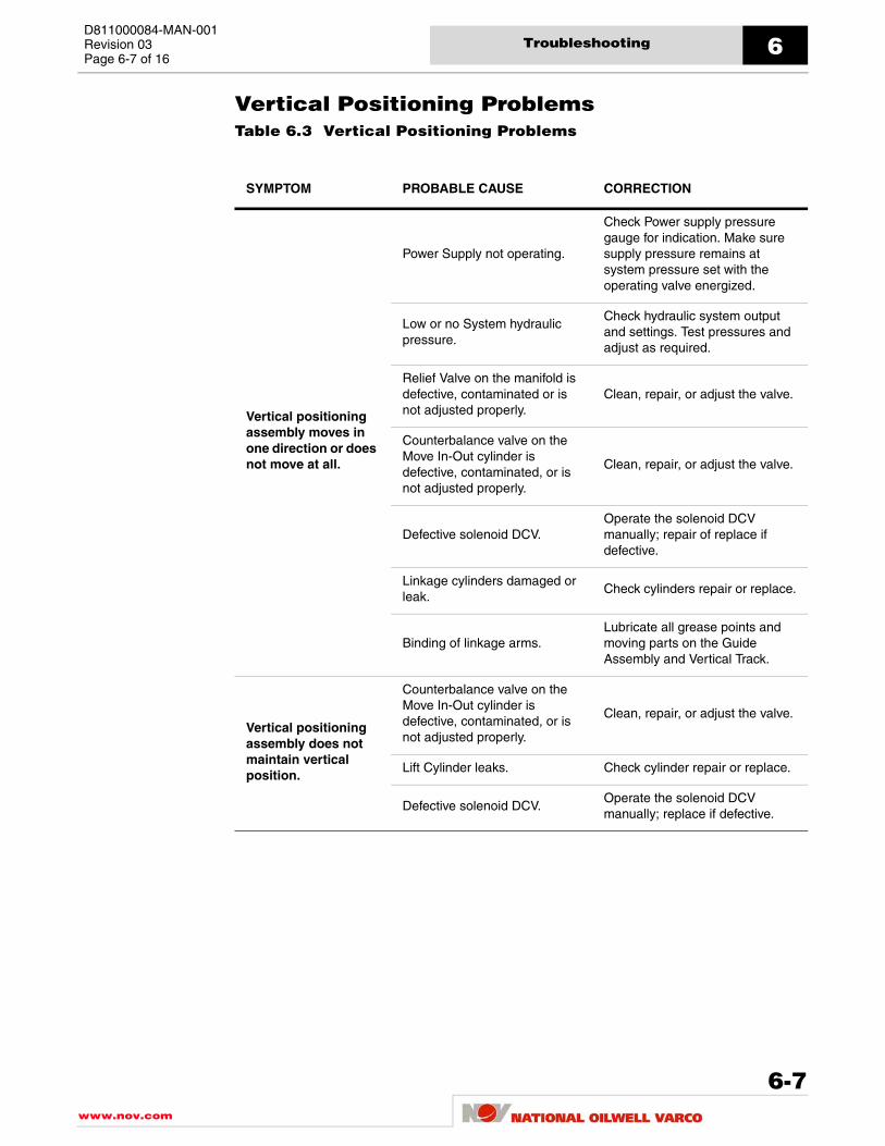
D811000084-MAN-001Revision 03Page 6-7 of 16
Troubleshooting 6
Vertical Positioning ProblemsTable 6.3 Vertical Positioning Problems
SYMPTOM PROBABLE CAUSE CORRECTION
Vertical positioning assembly moves in one direction or does not move at all.
Power Supply not operating.
Check Power supply pressure gauge for indication. Make sure supply pressure remains at system pressure set with the operating valve energized.
Low or no System hydraulic pressure.
Check hydraulic system output and settings. Test pressures and adjust as required.
Relief Valve on the manifold is defective, contaminated or is not adjusted properly.
Clean, repair, or adjust the valve.
Counterbalance valve on the Move In-Out cylinder is defective, contaminated, or is not adjusted properly.
Clean, repair, or adjust the valve.
Defective solenoid DCV.Operate the solenoid DCV manually; repair of replace if defective.
Linkage cylinders damaged or leak.
Check cylinders repair or replace.
Binding of linkage arms.Lubricate all grease points and moving parts on the Guide Assembly and Vertical Track.
Vertical positioning assembly does not maintain vertical position.
Counterbalance valve on the Move In-Out cylinder is defective, contaminated, or is not adjusted properly.
Clean, repair, or adjust the valve.
Lift Cylinder leaks. Check cylinder repair or replace.
Defective solenoid DCV.Operate the solenoid DCV manually; replace if defective.
6-7www.nov.com

Troubleshooting6D811000084-MAN-001
Revision 03Page 6-8 of 16
Troubleshooting Components
Troubleshooting Mechanical ComponentsThis section describes troubleshooting procedures for the Iron Roughneck mechanicalcomponents.
Wrench AssemblyTable 6.4 Wrench Assembly
SYMPTOM PROBABLE CAUSE CORRECTION
Torque Cylinder does not makeup
Low or no System hydraulic pressure.
Check hydraulic system output and settings. Test pressures and adjust as required.
Cylinder damaged. Seals leaking.
Check cylinders repair or replace.
Torque setting valve is not operating.
Inspect, isolate and replace.
Torque setting valve set too low. Increase torque setting pressure as required.
Torque setting valve stuck close, dirty, or defective.
Check torque setting valve, clean or replace.
Torque cylinder reaches its end of stroke before the torque set point is reached.
Recycle the torque wrench sequence for an additional makeup stroke to fully make up the tool joint.
Torque cylinder does not breakout.
Low or no System hydraulic pressure.
Check hydraulic system output and settings. Test pressures and adjust as required.
Torque cylinder drifts in makeup direction.
Sticking or worn solenoid DCV.Inspect solenoid DVC for contamination or wear, and repair or replace.
Torque cylinder drifts in breakout direction.
Sticking or worn solenoid DCV.
Inspect solenoid DVC for contamination or wear, and repair or replace. This also may occur over long periods of time with IR at idle, but hydraulic pressure is available. To avoid this turn off HPU when IR is not in use.
Torque cylinder does not move or moves slowly
Dirty return filter in HPU. Replace filter element.
Cylinder damaged. Seals leaking.
Check cylinders repair or replace.
Relief valve is not operating. Inspect, isolate and replace.
www.nov.com
6-8

D811000084-MAN-001Revision 03Page 6-9 of 16
Troubleshooting 6
Table 6.4 Wrench Assembly (continued)
SYMPTOM PROBABLE CAUSE CORRECTION
Top Jaw Wrench does not close
Low or no System hydraulic pressure.
Check hydraulic system output and settings. Test pressures and adjust as required.
Cylinder damaged. Seals leaking.
Check cylinders and repair or replace.
Jaw pressure relief valve is not operating. Stuck close, dirty, or defective.
Check Jaw pressure relief valve, clean, or replace.
Jaw pressure relief valve set too low.
Increase jaw pressure setting as required.
Top Jaw Wrench does not open.
Low or no System hydraulic pressure.
Check hydraulic system output and settings. Test pressures and adjust as required.
Cylinder damaged. Seals leaking.
Check cylinders and repair or replace.
Top Jaw Wrench cylinder drifts in close direction.
Sticking or worn solenoid DCV.Inspect solenoid DVC for contamination or wear, and repair or replace.
Cylinder damaged. Seals leaking.
Check cylinders repair or replace.
Top Jaw Wrench cylinder drifts in open direction.
Sticking or worn solenoid DCV.Inspect solenoid DVC for contamination or wear, and repair or replace.
Cylinder damaged. Seals leaking.
Check cylinders repair or replace.
Top Jaw Wrench cylinder does not move or moves slowly.
Cylinder damaged. Seals leaking.
Inspect cylinders repair or replace.
Dirty return filter in HPU. Replace filter element.
Top Jaw Wrench slips on tool joint.
Worn or broken dies. Replace dies.
Hydraulic pressure too low.
Check pressure setting, and increase as required.
Note: Set jaw pressure to correct clamping point set. Use caution not set jaw pressure setting too high, could cause damage or distort tool joint.
6-9www.nov.com

Troubleshooting6D811000084-MAN-001
Revision 03Page 6-10 of 16
Spinner AssemblyTable 6.5 Spinner Assembly
SYMPTOM PROBABLE CAUSE CORRECTION
Loss of power or torque.
Power supply is not operating.Check hydraulic system output and settings. Test pressures and adjust as required.
Restricted hydraulic lines.
Isolate cause of restriction and correct. Check for pinched, clogged, or otherwise obstructed hydraulic lines.
Worn or defective hydraulic motors.
Replace the hydraulic motors.
Worn or defective relief valves.Inspect, isolate, and replace relief valve cartridges.
Spinner Motors run irregularly.
Low or no System hydraulic pressure.
Check hydraulic system output and settings. Test pressures and adjust as required.
Contaminated motors.Inspect, and clean motors or replace.
Defective hydraulic motors.Repair hydraulic motors or replace.
Defective motor, solenoid DCV or relief valves.
Inspect, isolate, and repair or replace motors or valves.
Spinner motors stop rotating while spinning in or spinning out.
Flow to the motors is restricted.
Isolate cause of restriction and correct.
Defective hydraulic motors.Repair hydraulic motors or replace.
Hydraulic motor drive shaft is broken.
Repair hydraulic motor or replace.
Spinner Grip wheels do not rotate.
Low or no System hydraulic pressure.
Check hydraulic system output and settings. Test pressures and adjust as required.
Flow restricted.Isolate cause of restriction and correct.
Spinner Rotation Solenoid DCV is not operating. DCV is stuck close, dirty, or defective.
Inspect, isolate and replace. Check Spinner Rotation Solenoid DCV, clean or replace.
Sheared drive roller keys. Replace keys.
Defective hydraulic motors or broken motor drive shaft.
Repair hydraulic motors or replace.
www.nov.com
6-10

D811000084-MAN-001Revision 03Page 6-11 of 16
Troubleshooting 6
Table 6.5 Spinner Assembly (continued)
SYMPTOM PROBABLE CAUSE CORRECTION
Spinner Grip Wheels slip.
Insufficient clamping force.Check hydraulic system output and settings. Test pressures and adjust as required.
Coating on new drill pipe is making the surface too slippery.
Remove coating.
Contamination on spinner grip wheels.
Remove contamination.
Spinner grip wheels are worn. Replace spinner grip wheels.
Spinner Grip cylinder drifts in clamp or unclamp position.
Sticking or worn solenoid DCV.Inspect solenoid DVC for contamination or wear, and repair or replace.
Defective counterbalance valve or counterbalance valve is out of adjustment.
Replace or adjust CB valve to maintain clamp positioning with the operating valve in neutral.
Spinner Grip assembly does not clamp or unclamp.
Low or no System hydraulic pressure.
Check hydraulic system output and settings. Test pressures and adjust as required.
Flow restricted.Isolate cause of restriction and correct.
Cylinder damaged. Seals leaking.
Check cylinders and repair or replace.
Spinner Grip Solenoid DCV is not operating. DCV is stuck close, dirty, or defective.
Inspect, isolate and replace. Check Spinner Grip Solenoid DCV, clean or replace.
Spinner Grip assembly does not move in unison.
Lack of lubrication.Lubricate all grease points and moving parts.
Defective bearings in the cylinder end connection or spinner arm.
Repair or replace.
Defective linkage.Check the arm pins and bores and repair or replace.
Spinner Grip cylinder does not move or moves slowly.
Cylinder damaged. Seals leaking.
Inspect cylinders and repair or replace.
Dirty return filter in HPU. Replace filter element.
Power Supply is defective. Low or no System hydraulic pressure.
Check system output and settings. Test pressures and adjust as required.
6-11www.nov.com

Troubleshooting6D811000084-MAN-001
Revision 03Page 6-12 of 16
Table 6.5 Spinner Assembly (continued)
SYMPTOM PROBABLE CAUSE CORRECTION
Spinner does not shoulder pipe or cannot spin pipe after breakout sequence.
Hydraulic pressure low.Check hydraulic system output and settings. Test pressures and adjust as required.
Bottom jaw is clamped too high on the box end of drill pipe.
Unclamp the lower jaws, lower the Iron Roughneck to the lowest point on the box, re-clamp and spin in/out.
www.nov.com
6-12

D811000084-MAN-001Revision 03Page 6-13 of 16
Troubleshooting 6
Troubleshooting Hydraulic ComponentsThis section describes troubleshooting procedures for the IR3080 Iron Roughneck hydraulic components.
Hydraulic EnclosureTable 6.6 Hydraulic Enclosure
SYMPTOM PROBABLE CAUSE CORRECTION
Solenoid Directional Control Valve(s) Fail to Operate. Valve does not appear to shift.
Valve inoperative.Ensure Hydraulic Enclosure door is closed completely; otherwise limit switch will not set.
No electrical signal.
Check all wiring and insure signal form control is reaching the valve. Check to see if the voltage is too low or the line loss is excessive.
Bad Solenoid.Check coil resistance. Compare to good coil. Replace if more than 5% different.
Valve stuck.Try to use manual operation to see if valve will shift or feels stuck.
Component misadjusted.Investigate other circuit controls such as relief valves or flow controls.
Excessive hydraulic internal circuit leakage.
Check pilot pressure. See if the pilot pressure is adequate and the supply is stable.
Cylinder failed.
Try to determine if the cylinder is damaged. Check cylinder for internal bypass, by blocking lines to the cylinder, if full operating pressure is re-established at DCV. This positively indicates a bypass through the cylinder.
Inspect, isolate and replace.
6-13www.nov.com

Troubleshooting6D811000084-MAN-001
Revision 03Page 6-14 of 16
Torque Setting PanelTable 6.7 Torque Setting Panel
SYMPTOM PROBABLE CAUSE CORRECTION
Relief Valve fail to function properly
No hydraulic pressure.Check hydraulic system output and settings. Test pressures and adjust as required.
Hydraulic lines incorrectly connected.
Check hydraulic lines are connected properly.
Relief valve defective and/or damaged.
Inspect, isolate and replace.
Torque Gauge does not return to zero.
Gauge not adjusted to zero.Reset gauge and recheck torque setting.
Defective gauge. Replace.
www.nov.com
6-14

D811000084-MAN-001Revision 03Page 6-15 of 16
Troubleshooting 6
Troubleshooting System Components
Electrical and Control System Components
The electrical and control system configuration described in this section are typical, butnot universal. Refer to the Iron Roughneck Control Console operation manual fordescription of operation and see your technical drawings parts list manual for electricaland control system diagrams and information.
The Iron Roughneck control system consists of a remote control console and serviceloops connected to and from a combination of a few basic types of components.
Inputs from the operator and feedback on machine movement are directed into the remotecontrol console. The control console also initiates the system's outputs.
If a particular function on the Iron Roughneck is not working, determine if the control system received the input and if the corresponding output was energized.
If an input is valid but the related output does not perform correctly, either the control system and/or its related hardware have failed, or an interlock condition exits.
Troubleshooting a problem with the control system involves determining which of thecontrol systems components has failed.
Follow appropriate electrical diagnostic procedures to check the Iron Roughneck electrical components and consult the corresponding troubleshooting tables.
To determine the state of a component testing should be preformed by a qualifiedelectrician.
Replace any faulty electrical components upon detection.
If you cannot bring the control system into the operating mode. Contact National OilwellVarco for additional information.
6-15www.nov.com

Troubleshooting6D811000084-MAN-001
Revision 03Page 6-16 of 16
This page is intentionally left blank.
www.nov.com
6-16

www.nov.com
RIG/PLANT
ADDITIONAL CODE SDRL CODE TOTAL PGS
REMARKS
MAIN TAG NUMBER DISCIPLINE
CLIENT PO NUMBER
CLIENT DOCUMENT NUMBER
Client Document Number
Technical Drawing Package
REFERENCE
1100012 REFERENCE DESCRIPTION
IR3080 Iron Roughneck, 88" Arm This document contains proprietary and confidential information which is the property of National Oilwell Varco, L.P., its affiliates or subsidiaries (all collectively referred to hereinafter as "NOV"). It is loaned for limited purposes only and remains the property of NOV. Reproduction, in whole or in part, or use of this design or distribution of this information to others is not permitted without the express written consent of NOV. This document is to be returned to NOV upon request or upon completion of the use for which it was loaned. This document and the information contained and represented herein is the copyrighted property of NOV. © National Oilwell Varco
National Oilwell Varco RIG SOLUTIONS
12950 West Little York Houston, TX 77041
DOCUMENT NUMBER
D811000104-DOS-001 REV
02
IR3080Iron Roughneck, 88" Arm

Document number D811000104-DOS-001 Revision 02Page 2
www.nov.com
REVISION HISTORY
02 26.09.2007 Updated format J.Kellstrom B. Dominguez K. Schmidt 01 10/2/2007 First Issue BMD BMD KS Rev Date (dd.mm.yyyy) Reason for issue Prepared Checked Approved
CHANGE DESCRIPTION
Revision Change Description 02 Removed the words description,drawing no.,and rev.,removed all revision levels from document 01 First issue

Document number D811000106-DOS-001 Revision 02Page 3
www.nov.com
TECHNICAL DRAWING PACKAGE This document provides a list of drawings for the model IR3080 Iron Roughneck, reference number 1100012. The actual drawings are arranged in the binder, in numerical order.
DRAWINGS BY ASSEMBLY
General Iron Roughneck Assembly ............................................................................ …....1100012
Iron Roughneck General Assembly .............................................................. .IR3080GA02
Lifting Skid Assembly .................................................................................... .………..LS02
Hydraulic Schematic ...................................................................................... .……….HC04
Column/Guide/Arm Assembly Arm Assembly, 88" ......................................................................................... ………..AR06
Link Assembly ...................................................................................... …….AR06-03
Link Assembly, Upper-Right ....................................................... ...AR03-03-01
Link Assembly, Lower-Right ....................................................... ...AR03-03-02
Link Assembly, Lower-Left,......................................................... ...AR03-03-03
Link, Single Right Arm ............................................................... ...AR03-03-04
Link, Single Left Arm .................................................................. ...AR03-03-05
Vertical Track Assembly ....................................................................... ..…..AR06-08
Guide Assembly ................................................................................... ….AR06-07A
Spinner Assembly Spinner Assembly .......................................................................................... …….1100189
Wrench Assembly Wrench Assembly .......................................................................................... ……..1100154
Electrical Controls IR Internal Wiring Diagram............................................................................. ..IRC6-803-03
Control Console (GAD) .................................................................................. 0001-0403-52
Electro-Hydraulic Assembly (GAD) ................................................................ 0001-0403-53
Hydraulic Enclosure (GAD) .................................................................. 0001-0403-54
Solenoid J-Box (GAD) .......................................................................... 0001-0403-15
ERLS J-Box (GAD)..........................................................................................0001-0365-61

Document number D811000104-DOS-001 Revision 02Page 4
www.nov.com
DRAWINGS IN NUMERICAL ORDER
ERLS J-Box (GAD).............................................................................................0001-0365-61
Solenoid J-Box (GAD) ....................................................................................... 0001-0403-15
Control Console (GAD)...................................................................................... 0001-0403-52
Electro-Hydraulic Assembly (GAD) ................................................................... 0001-0403-53
Hydraulic Enclosure (GAD) ............................................................................... 0001-0403-54
Iron Roughneck Assembly ................................................................................ …....1100012
Wrench Assembly.............................................................................................. ……..1100154
Spinner Assembly.............................................................................................. …….1100189
Link Assembly, Upper-Right............................................................................... ...AR03-03-01
Link Assembly, Lower-Right .............................................................................. ...AR03-03-02
Link Assembly, Lower-Left, ............................................................................... ...AR03-03-03
Link, Single Right Arm ...................................................................................... ...AR03-03-04
Link, Single Left Arm ........................................................................................ ...AR03-03-05
Arm Assembly, 88" ............................................................................................ ………..AR06
Link Assembly .................................................................................................... …….AR06-03
Guide Assembly ................................................................................................ ….AR06-07A
Vertical Track Assembly .................................................................................... ..…..AR06-08
Hydraulic Schematic ......................................................................................... .……….HC04
Iron Roughneck General Assembly .................................................................. .IR3080GA02
IR Internal Wiring Diagram ................................................................................ ..IRC6-803-03
Lifting Skid Assembly ....................................................................................... .………..LS02

***
*
A
DATE
SIZE REV
SCALE EST WT SHEET
TITLE
DRAWING No.DATE
DATE
DATE
CHECKED BY
P.E. APPROVAL
DIMENSIONS ARE IN INCHES
FILLET RADII CONCENTRICITY
SQUARENESSPARALLELISMRFS EXCEPT WHEN M MODIFIED
DIMENSIONAL TOL.
ANGLE ± .50 DEGREESURFACE RMS
FRACTIONS ±X.XXX ±X.XX ±
X.X ±
BREAK SHARP CORNERS
NEXT ASS'Y
SIMILAR TO
APPLICABLE SPECS
DESIGNED BY
DRAWN BY
MATERIAL SPEC
D
12345678
A
B
C
D
8 7 6 5 4 3 DWG No. SHT 1
D
C
B
AUNLESS OTHERWISE SPECIFIED
B10-27-0510/31/05BRIAN D. WINTER
N. HAPPACHER 11000121 OF 2
1100012 1
9304 LBS1:10
IRON ROUGHNECK, IR3080, 88" ARM AUTO-ROTATION
SEE L/M
C. LACKEY
26-OCT-05
1/32
1/64
.015
.03
.1
250
THIS DOCUMENT CONTAINS PROPRIETARY ANDCONFIDENTIAL INFORMATION WHICH BELONGS TONATIONAL-OILWELL, L.P.. IT IS LOANED FOR LIMITEDPURPOSES ONLY AND REMAINS THE PROPERTY OFNATIONAL-OILWELL, L.P.. REPRODUCTION, IN WHOLEOR IN PART, OR USE OF THIS DESIGN ORDISTRIBUTION OF THIS INFORMATION TO OTHERS ISNOT PERMITTED WITHOUT THE EXPRESS WRITTENCONSENT OF NATIONAL-OILWELL, L.P.. THISDOCUMENT IS TO BE RETURNED TO NATIONAL-OILWELL, L.P. UPON REQUEST AND IN ANY EVENTUPON COMPLETION OF THE USE FOR WHICH IT WASLOANED. THIS DOCUMENT AND THE INFORMATIONCONTAINED AND REPRESENTED HEREIN IS THECOPYRIGHTED PROPERTY OF NATIONAL-OILWELL, L.P.
PROPRIETARY INFORMATION
35
36
5
34
28 30
25
26
1
3839
2
41 42
18 19
32 31
20
3
3
4
NOTES:
ITEMS NOT SHOWN FOR CLARITY.1.PLEASE SEE LSO2 FOR ASSEMBLY TO SKID.2.WORK WITH DWG'S HF09, LS02, HCO43.APPLY ANTI-SEIZE COMPOUND TO ALL THREADS.4.APPLY SILICON TO ITEM 36 BEFORE ASSEMBLY.5.
***
22 21
B 45 3 7800069 ADAPTER, AEROQUIP 2021-8-8S .20 44 2 6300109 NUT, HEX 1/2"-13 304 SST .04 43 2 sp01-11 EYEBOLT, 1/2"-13UNC x 6" SST .38 42 4 6500816s PIN, COTTER 1/8 X 2, SST .00 41 4 ar01-18 PIN, SPINNER SPRING CONNECTION .43 40 2 ir3080ar55-09 SPRING, TENSION 1 39 2 sp01-09 SPRING BRACKET ASSEMBLY 22 38 1 ar01-12 TOP SPINNER HEAD FRAME SUPPORT .00 37 4 0-7601-1060-06 SCREW, DRIVE #6 X 3/8 TYPE U SST .00 36 1 0000-9641-69 INDICATOR, DIGITAL PNL MTG. .00 35 1 0001-0403-52 IR REMOTE CONTROL CONSOLE 252 34 1 0000-9657-28 IR3080 HYDRAULIC TORQUE GAGE 1.00 33 1 0001-0365-61 J-BOX, ERLS 24 32 4 700030311 SCREW, HEX HD 1/2-13 X 1 GR5 CD PL .10 31 4 7619050 WASHER, REG SPG LOCK 1/2" CD PL .01 30 2 5507071 U-BOLT .31 29 9 7000209-30 SCREW, HEX HD CAP 3/8"-16 X 1-1/4" LG SST .06 28 1 AR04-40 BRACKET, CABLE 3 27 1 7822179 WRAP, PROTECTIVE GHX R50SSG 20 METERS PER BOX .00 26 10 7802353 CLAMP, HYDRA-ZORB #200075 .84 25 41 78096004 CLAMP, HYDRA-ZORB #200050 .67 24 4 7629024 WASHER, FLAT 3/8" N TYPE A 0.812 OD 316 SST .01 23 1 ar03-15 BRACKET, ERLS J-BOX MOUNT 7 22 4 700020830 SCREW, HEX HD CAP 3/8"-16 X 1" LG SST .05 21 11 6308070 NUT, HEX 3/8"-16UNC SST NYLOC .02 20 4 AR06-03-13 KEEPER, PIN .25 19 4 SP01-03-06 GREASE FITTING 1/4-28 UNF STRAIGHT .00 18 4 AR03-03-08E PIN, WRENCH F/ 88" ARM 5 17 2 7616041 WASHER, REG SPG LOCK 3/8 304 SST .00 16 1 6501228S COTTER PIN, 3/16 x 3 1/2 LG SST .00 15 1 7622130 WASHER, FLAT, 1-1/4" TYP B, 3-1/2 OD CP .59 14 1 AR01-17 PIN, SPINNER HANGER / WRENCH SUPPORT 2 13 2 700054121t SCREW, HEX HD CAP 1"-8 X 6-3/4" GR8 CD PL 1.00 12 8 7621052 WASHER, FLAT 1" N TYPE A 2.000 OD CD PL .09 11 4 n1unc-ss NUT, HEXHD 1"-8 UNC, SS .00 10 6 nl1unc-ss NUT,LOCK 1"-8 UNC SS .00 9 2 bw01-26 STUD, 1"-8 UNC X 8 TEFLON COAT 2 8 1 ss02-01 TAG, IRON ROUGHNECK .00 7 1 hf09 HOSE KIT, IR WITH ROTATION SYSTEM .00 6 1 ls02 SKID, SHIPPING 88" IR .00 5 1 0001-0403-53 IR ELECTRO-HYDRAULIC ASSEMBLY 111 4 1 ar06-06-01 WRENCH FRAME, (MACHINING & WELDMENT) 237 3 1 ar06 ASSEMBLY, ARM 88" REACH WITH ROTATION 4440 2 1 1100189 SPINNER ASSEMBLY F/ IR3080 915 1 1 1100154 WRENCH ASSY (IR3080) 0
ITEM NO. QTY. PART NO. DESCRIPTION / MATERIAL / SPECIFICATION WT. EA.
LTR DESCRIPTION OF CHANGE MADE CHKD DATE APPD
A ITEM 35 WAS P/N 0001-0403-51 CEL NH 04-Feb-06 BDW
B ADDED ITEM 45 CEL NH 21-Feb-06 BDW

LTR DESCRIPTION OF CHANGE MADE CHKD DATE APPD
4142
8 37
29
24
28
23 29
17
30
45
B
DATE
SIZE REV
SCALE EST WT SHEET
TITLE
DRAWING No.DATE
DATE
DATE
CHECKED BY
P.E. APPROVAL
DESIGNED BY
DRAWN BY
D
12345678
A
B
C
D
8 7 6 5 4 3 DWG No. SHT 1
D
C
B
A
B10-27-0510/31/05BRIAN D. WINTER
N. HAPPACHER 11000122 OF 2
1100012 2
-----1:8
IRON ROUGHNECK, IR3080, 88" ARM AUTO-ROTATION
C. LACKEY
26-OCT-05
THIS DOCUMENT CONTAINS PROPRIETARY AND CONFIDENTIAL INFORMATIONWHICH BELONGS TO NATIONAL-OILWELL, L.P.. IT IS LOANED FOR LIMITED PURPOSESONLY AND REMAINS THE PROPERTY OF NATIONAL-OILWELL, L.P.. REPRODUCTION, INWHOLE OR IN PART, OR USE OF THIS DESIGN OR DISTRIBUTION OF THISINFORMATION TO OTHERS IS NOT PERMITTED WITHOUT THE EXPRESS WRITTENCONSENT OF NATIONAL-OILWELL, L.P.. THIS DOCUMENT IS TO BE RETURNED TONATIONAL-OILWELL, L.P. UPON REQUEST AND IN ANY EVENT UPON COMPLETION OF THEUSE FOR WHICH IT WAS LOANED. THIS DOCUMENT AND THE INFORMATION CONTAINEDAND REPRESENTED HEREIN IS THE COPYRIGHTED PROPERTY OF NATIONAL-OILWELL, L.P..
PROPRIETARY INFORMATION
5
4344
40
41 42
3938
39
4
3
10 9 1211
141516
10 13
38
18 19 20
3231
21 29
33
LTR DESCRIPTION OF CHANGE MADE CHKD DATE APPD


LTR DESCRIPTION OF CHANGE MADE CHKD DATE APPD
28
27
31
31
1917
1618
20 12 24
7
15
22
SCALE 1 : 2
23
DETAIL A
21
10 20
5
430
142928 16 18
3535
A
M
DATE
SIZE REV
SCALE EST WT SHEET
TITLE
DRAWING No.
DATE
DATE
DATE
CHECKED BY
P.E. APPROVAL
DIMENSIONS ARE IN INCHES
FILLET RADII
CONCENTRICITY
SQUARENESS
PARALLELISM
RFS EXCEPT WHEN MODIFIED
DIMENSIONAL TOL.
ANGLE ± .50 DEGREE
SURFACE RMS
FRACTIONS ±
X.XXX ±
X.XX ±
X.X ±
BREAK SHARP CORNERS
NEXT ASS'Y
SIMILAR TO
APPLICABLE SPECS
DESIGNED BY
DRAWN BY
MATERIAL SPEC
D
12345678
A
B
C
D
8 7 6 5 4 3 DWG No. SHT 1
D
C
B
AUNLESS OTHERWISE SPECIFIED
10-24-05
10/31/05B.D. WINTER
N. HAPPACHER AR061 OF 1
AR06 1
4440 LBS1:10
ASSEMBLY, ARM 88" REACH WITH ROTATION
SEE L/M
C. LACKEY
21-OCT-05
1/32
1/64
.015
.03
.1
250
THIS DOCUMENT CONTAINS PROPRIETARY AND
CONFIDENTIAL INFORMATION WHICH BELONGS TO
NATIONAL-OILWELL, L.P.. IT IS LOANED FOR LIMITED
PURPOSES ONLY AND REMAINS THE PROPERTY OF
NATIONAL-OILWELL, L.P.. REPRODUCTION, IN WHOLE
OR IN PART, OR USE OF THIS DESIGN OR
DISTRIBUTION OF THIS INFORMATION TO OTHERS IS
NOT PERMITTED WITHOUT THE EXPRESS WRITTEN
CONSENT OF NATIONAL-OILWELL, L.P.. THIS
DOCUMENT IS TO BE RETURNED TO NATIONAL-
OILWELL, L.P. UPON REQUEST AND IN ANY EVENT
UPON COMPLETION OF THE USE FOR WHICH IT WAS
LOANED. THIS DOCUMENT AND THE INFORMATION
CONTAINED AND REPRESENTED HEREIN IS THE
COPYRIGHTED PROPERTY OF NATIONAL-OILWELL, L.P.
PROPRIETARY INFORMATION
3
2
4
6
31
6
131734
30
9 18 16
14
26
5 10 20
112032
1618
31
1 15
258
33
35 2 7819301 TEE, AEROQUIP 203003-8-8S .33
34 9 7619050 WASHER, REG SPG LOCK 1/2" CD PL .01
33 4 700030311 SCREW, HEX HD 1/2-13 X 1 GR5 CD PL .10
32 4 AR06-03-13 KEEPER, PIN .25
31 2 7804213 ELBOW, AEROQUIP 2062-12-8S .64
30 2 7804216 ELBOW, AEROQUIP 2062-8-8S .36
29 1 7804510 ELBOW, AEROQUIP FF5540-2016S 2
28 1 7804379 ELBOW, AEROQUIP FF5540-20-20S 2
27 2 780585620 FLANGE KIT, AEROQUIP FF595-20 CODE 62 2
26 1 HC01-10 HIGH PRESSURE FILTER ASSY. 25
25 2 AR03-12C PIN, LINKAGE CYLINDER 1.00
24 1 6501228S COTTER PIN, 3/16 x 3 1/2 LG SST .00
23 8 7600126 WASHER, FLAT 3/8" W TYPE A 1.000 OD 304 SST .01
22 4 7480598 NUT, 3/8-16 NYLOCK SS .02
21 4 700020830 SCREW, HEX HD CAP 3/8"-16 X 1" LG SST .05
20 7 SP01-03-06 GREASE FITTING 1/4-28 UNF STRAIGHT .00
19 4 NL.50UNC-SS NUT, HEX HD 1/2-13 UNC NYLOCK SST .05
18 12 7619041 WASHER, REG SPG LOCK 3/8" CD PL .01
17 8 700030511 SCREW, HEX HD CAP 1/2-13UNC x 1 1/2 GR5 CD PL .04
16 12 700020811 SCREW, HEX 3/8-16UNC X 1" LG CD PL .05
15 2 AR03-33 LOGO, 88" IRON ROUGHNECK ARM 6
14 1 ar03-07-08 HYDRAULIC CONSOLE SUPPORT WELDMENT 5
13 2 AR01-10-03 CLAMP F/ GUIDE ASSEMBLY 1
12 1 AR01-19 PIN, LIFTING CYLINDER 5
11 4 AR03-03-08B PIN, LINKAGE 4
10 2 AR03-03-08C PIN, CLEVIS 2
9 3 AR03-03-13B KEEPER, PIN .00
8 2 AR03-03-13A KEEPER, PIN .00
7 1 ar01-08_01 LIFT CYL KNUCKLE 16
6 1 AR03-13A CYLINDER, LIFT 261
5 2 ar03-12b CLEVIS, FOR LINKAGE CYLINDER .00
4 2 AR03-12A CYLINDER, LINKAGE 67
3 1 AR06-08 ASSEMBLY, VERTICAL TRACK 1653
2 1 AR06-07A ASSEMBLY, GUIDE FOR 88" ARM 839
1 1 AR06-03 ASSEMBLY, LINK FOR 88" IR ARM
ITEM NO. QTY. PART NO. DESCRIPTION / MATERIAL / SPECIFICATION WT. EA.
LTR DESCRIPTION OF CHANGE MADE CHKD DATE APPD


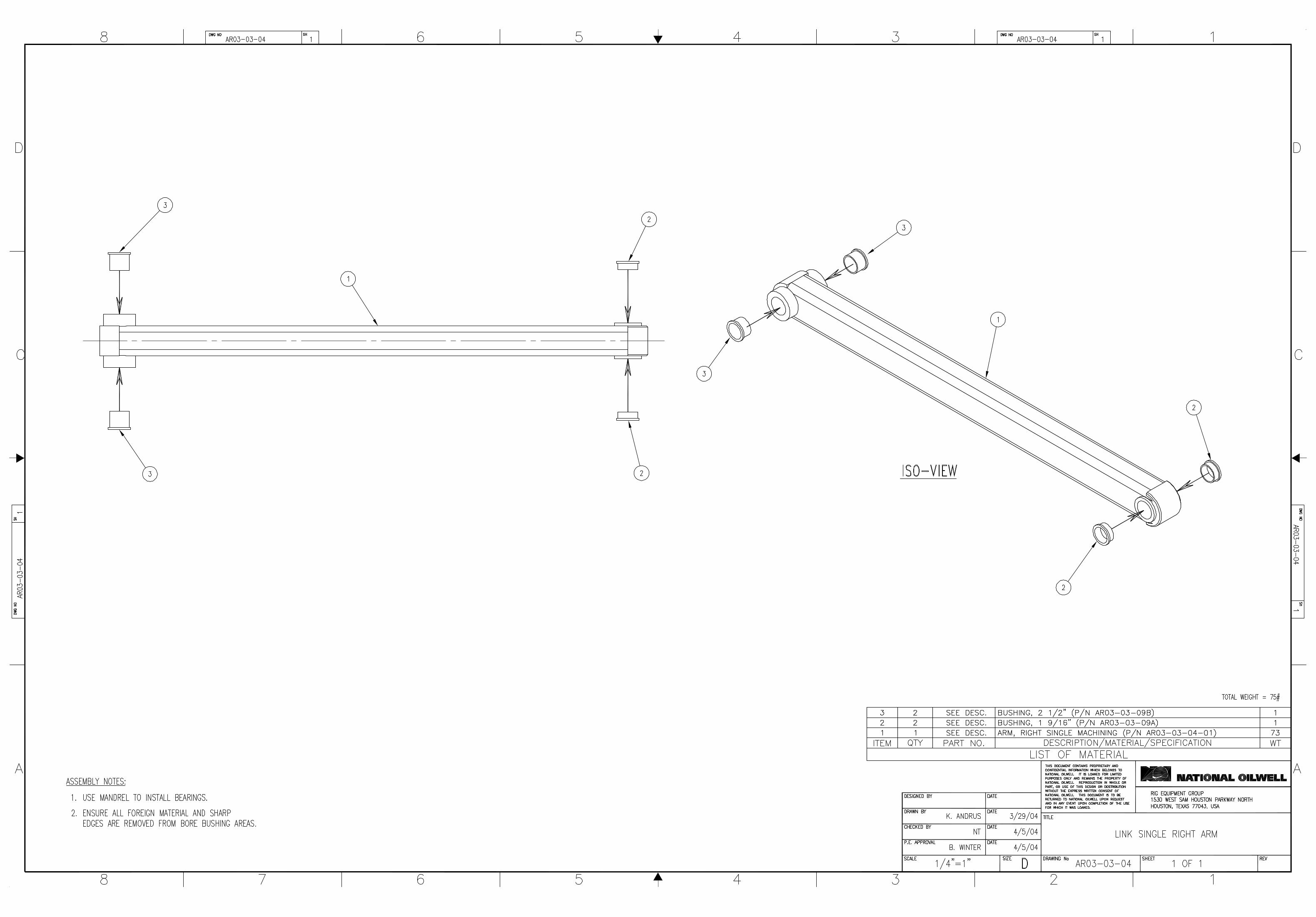


1
SECTION A-A SCALE 1 : 4
13 14
1314
5
1
35
35
1
5
7 9 11 20
35
31
E
22
1
19
31
2
37 8 7000106-11 SCREW, HEX HD CAP 1/4"-20 X 3/4" LG GR5 CD PL .02 36 1 7634048 WASHER, NORDLOCK NL16 5/8" (M16) ZINC PL .00 35 2 7804376 ELBOW, AEROQUIP 2062-4-4S .11 34 2 7800069 ADAPTER, AEROQUIP 2021-8-8S .00 33 2 7844096 SWITCH, GO TOPWORX 31-17524-F4 .82 32 8 7619033 WASHER, REG SPG LOCK 1/4" CD PL .00 31 2 7800190 ADAPTER, AEROQUIP 202702-10-8S .03 30 3 7612018C WASHER, HI-COLLAR SPG LOCK 1/2 CD PL .01 29 3 700630708 SCREW, HEX SOC HD CAP 1/2-13 X 2 CD PL .16 28 2 700020811 SCREW, HEX 3/8-16UNC X 1" LG CD PL .05 27 2 7634028 WASHER, NORDLOCK NL3/8 3/8" ZINC PL .00 26 7 7000206-11 SCREW, HEX HD CAP 3/8-16 X 3/4 GR5 CD PL .00 25 7 7619041 WASHER, REG SPG LOCK 3/8" CD PL .01 24 1 AR06-08-04 RETAINER, PINION GEAR 88" ARM .60 23 1 AR06-08-03 GEAR COVER, RIGHT HAND 25.118.422 1 AR06-08-02 GEAR COVER, LEFT HAND 26.018.421 1 AR06-11 PINION GEAR, F/ 88" ARM IR 7 20 16 7007306 SCREW, HEX SOC FLAT HD CAP 1/2-13 X 1-3/4 CD PL .11 19 2 1100269 SENSOR CLAMP, 88" ROTATION .40 18 1 HF03-11A HOSE ASSEMBLY17 1 7805144 FITTING, GREASE ALEMITE #1627-B .00 16 1 7804540 ELBOW, AEROQUIP 2024-4-4S .11 15 1 7800229 ADAPTER, AEROQUIP 2021-4-4S .07 14 46 7634056 WASHER, NORDLOCK NL3/4 3/4" ZINC PL 13 42 7000446-21 SCREW, HEX HD CAP 3/4-10 X 3-1/2 GR 8 CD PL .58 12 1 7000394-11F SCREW, HEX HD CAP 5/8-18 X 1-1/4 GR5 CD PL .19 11 8 AR01-11-07 SHIM 1/16" .39 10 8 AR01-11-06 SHIM 1/8" .78 9 8 AR01-11-05 SHIM 1/4" 2 8 8 AR01-11-04 SHIM 3/8" 2 7 8 AR01-11-03 SHIM1/2" 3 6 1 HM002 MOTOR, HYDRAULIC WITH BRAKE 49 5 1 AR06-09-01 BASE, ROTATION MACHINING 339 4 1 AR06-10 BEARING, KAYDON MTE-470 145 3 4 700043611 SCREW, HEX HD CAP 3/4-10 X 1 CD PL .27 2 2 1100290 ROTATION TARGET, 88" ARM 1.00 1 1 ar06-08-01 TRACK, VERTICAL MACHINING 935
ITEM NO. QTY. PART NO. DESCRIPTION / MATERIAL / SPECIFICATION WT. EA.
NOTES:
1. BEARING MOUNTING SURFACES OF ITEMS 1 & 5 SHOULD BE CLEANED AND FREE OF PAINT.
2. TORQUE ITEM 13 TO 360 FT-LBS IN A STAR PATTERN. 3. ITEM 34 SHOULD HAVE 1/8" SPACING FROM ITEM 2. 4. APPLY ANTI-SEIZE COMPOUND TO ALL THREADED FASTENERS.
5. GREASE BEARING AFTER ASSEMBLY.
B
22
6
23
31
35
25 26
17
A
A
DATE
SIZE REV
SCALE EST WT SHEET
TITLE
DRAWING No.DATE
DATE
DATE
CHECKED BY
P.E. APPROVAL
DIMENSIONS ARE IN INCHES
FILLET RADII CONCENTRICITY
SQUARENESSPARALLELISMRFS EXCEPT WHEN M MODIFIED
DIMENSIONAL TOL.
ANGLE ± .50 DEGREESURFACE RMS
FRACTIONS ±X.XXX ±X.XX ±
X.X ±
BREAK SHARP CORNERS
NEXT ASS'Y
SUPERSEDES
SUPERSEDED BY
SIMILAR TO
APPLICABLE SPECS
LAYOUT No.
PROPRIETARY INFORMATION
DESIGNED BY
DRAWN BY
MATERIAL SPEC
D
THIS DOCUMENT CONTAINS PROPRIETARY ANDCONFIDENTIAL INFORMATION WHICH BELONGSTO NATIONAL OILWELL. IT IS LOANED FOR LIMITEDPURPOSES ONLY AND REMAINS THE PROPERTYOF NATIONAL OILWELL. REPRODUCTION, IN WHOLE ORIN PART, OR USE OF THIS DESIGN OR DISTRIBUTIONOF THIS INFORMATION TO OTHERS IS NOT PERMITTEDWITHOUT THE EXPRESS WRITTEN CONSENT OFNATIONAL OILWELL. THIS DOCUMENT IS TO BERETURNED TO NATIONAL OILWELL UPON REQUESTAND IN ANY EVENT UPON COMPLETION OF THE USEFOR WHICH IT WAS LOANED.
12345678
A
B
C
D
8 7 6 5 4 3 DWG No. SHT 1
D
C
B
AUNLESS OTHERWISE SPECIFIED
B2/3/052/3/05BRIAN WINTER
BRIAN WINTER AR06-081 OF 2
AR06-08 1
1649.7 LBS1:8
ASSEMBLY, VERTICAL TRACK
SEE L/M
C. LACKEYB. WINTER 14-SEP-04
24-SEP-04
1/32
1/64
.015
.03
.1
27
18
15
29 624
4
ORIENT FITTING ANDHOSE AS SHOWN
2
3
28
16
33
DETAIL E SCALE 1 : 2 2
1/8"
LTR DESCRIPTION OF CHANGE MADE CHKD DATE APPD
REMOVED ITEMS 45, 46, 47
ITEM 14 WAS QTY 42, ITEM 34 WAS QTY 4
A ITEM 2 WAS P/N ARO6-09-02 CEL NH 19-Oct-05 BDW
B ITEM 19 WAS P/N 221312/005 CEL BDW 12-May-06 BDW

25
26
13 14 4 2
1011
78
9
13
14
5
1
3333
20
31 31
3529
30
2526
16
15 4
21 24
1236
1937
3227 28
34
34
22
3 14
35
DATE
SIZE REV
SCALE EST WT SHEET
TITLE
DRAWING No.DATE
DATE
DATE
CHECKED BY
P.E. APPROVAL
PROPRIETARY INFORMATION
DESIGNED BY
DRAWN BY
D
THIS DOCUMENT CONTAINS PROPRIETARY AND CONFIDENTIAL INFORMATIONWHICH BELONGS TO NATIONAL OILWELL. IT IS LOANED FOR LIMITED PURPOSESONLY AND REMAINS THE PROPERTY OF NATIONAL OILWELL. REPRODUCTION,IN WHOLE OR IN PART, OR USE OF THIS DESIGN OR DISTRIBUTION OF THISINFORMATION TO OTHERS IS NOT PERMITTED WITHOUT THE EXPRESS WRITTENCONSENT OF NATIONAL OILWELL. THIS DOCUMENT IS TO BE RETURNED TONATIONAL OILWELL UPON REQUEST AND IN ANY EVENT UPON COMPLETIONOF THE USE FOR WHICH IT WAS LOANED.
12345678
A
B
C
D
8 7 6 5 4 3 DWG No. SHT 1
D
C
B
A
B2/3/052/3/05BRIAN WINTER
BRIAN WINTER AR06-082 OF 2
AR06-08 2
1:5
ASSEMBLY, VERTICAL TRACK
C. LACKEYB. WINTER 14-SEP-04
24-SEP-04
LTR DESCRIPTION OF CHANGE MADE CHKD DATE APPD
A SEEE SHT 1 FOR DETAILS

11
6
7
10
12
214
13
19 20
76
13
18
5
10
9
12
4
4
15 21
11
11
13 3
41
5
10
5
16 17 14
1
8
8
13
3
912
4
5 10
2
10
12
9 12
14 17
17
14
1 1100163 MOUNTING PLATE, ROTATION MANIFOLD 214 7401116 NUT, 1/2-13 NYLOCK 204 7000306-11 SCREW, HEX HD CAP 1/2"-13 X 1-3/4" LG GR5 CD PL 19
16 AR06-07-07D WEAR PAD SHIM 184 g7800108 ADAPTER, AEROQUIP 202702-6-8S 172 7619041 WASHER, REG SPG LOCK 3/8" CD PL 162 700022311 SCREW, HEX HD CAP 3/8-16 X 4-3/4 GR5 CD PL 153 0-7601-2130-60 ADAPTER, AEROQUIP 202702-6-4S 141 1100279 ASSEMBLY, ROTATION MANIFOLD 1328 7619050 WASHER, REG SPG LOCK 1/2" CD PL 124 0-7601-2070-44 FITTING, GREASE HYD 1/4 X 37/64 1116 700030511 SCREW, HEX HD CAP 1/2-13UNC x 1 1/2 GR5 CD PL 1024 700030411 SCREW, HEX HD CAP 1/2"-13 X 1-1/4" LG GR5 CD PL 92 ar03-03-09d BUSHING, ORKOT 1-1/4 OD X 1 ID X 1.37 LG 84 ar01-07-01 NUT, LOCK 2" (1 1/2" TK.) GR5, GALV. 74 ar01-07 CAM FOLLOWER BEARING 68 AR06-07-07C WEAR PAD DETAILS 52 AR06-07-07B FRONT SIDE GUIDE WELDMENT 44 AR03-07-07A REAR SIDE GUIDE WELDMENT 31 AR03-07-06 PLATE, TRUNNION 21 AR06-07-01 GUIDE, MACHINING 88" 1
QTY PART NUMBER DESCRIPTION MATERIAL ITEM
ACTUAL WT: 845 LBS
THIS DOCUMENT CONTAINS PROPRIETARY AND CONFIDENTIAL INFORMATION WHICH BELONGS TO NATIONAL OILWELL VARCO,L.P., ITS AFFILIATES OR SUBSIDIARIES (ALL COLLECTIVELY REFERRED TO HEREINAFTER AS "NOV"). IT IS LOANED FOR LIMITED PURPOSES ONLY AND REMAINS THE PROPERTY OF NOV. REPRODUCTION, IN WHOLE OR IN PART, OR USE OF THIS DESIGN OR DISTRIBUTION OF THIS INFORMATION TO OTHERS IS NOT PERMITTED WITHOUT THE EXPRESS WRITTEN CONSENT OF NOV. THIS DOCUMENT IS TO BE RETURNED TO NOV UPON REQUEST OR UPON COMPLETION OF THE USE FOR WHICH IT WAS LOANED. THIS DOCUMENT AND THE INFORMATION CONTAINED AND REPRESENTED HEREIN IS THE COPYRIGHTED PROPERTY OF NOV.
PRODUCT: IRON ROUGHNECKEND ITEM:
INITIALCURRENT
DRAWN
DATE
CHECKED
APPVD
WT LBS:
SIMILAR TO:
NEXT ASSY:
TOL > ±.06
FINISHUNLESS OTHERWISE SPECIFIEDTOL < ±.06
8/23/04
B. WINTER
NT
K. ANDRUS
09/18/2009
J. WALKER
E. AXELSON
E. GARDUNO
1000250
845AR06-07
1 OF 1
SW FILE NAME: ar06-07a
DO NOT SCALE DRAWING
B
CC
B
2
D
13457 6
D
8
A
8 7 6 5 4 2 1
A
3
TITLE:
DWG NO.
SCALE: PROJECTION: SIZE: SHT:
REV:
AR06-07A B
ASSEMBLY, F/ 88" ARM
1:5RIG SOLUTIONS
MECHANICAL ENGINEERING
DRAWN IN SWRS-MECH_D-TPL-001
D
UNLESS OTHERWISE SPECIFIED DIMENSIONS ARE IN INCHES.TOLERANCES ARE:
1/32
±.50 DEG±.1
±.03
±.015
±1/64
X.XXX
X.XX
X.X
FRACTIONS
BREAK EDGES
ANGLES

42 3/4"
CC
DD
AA
2
1
21
22
3
9
23
23
29299
23
3
2624
8
10
10
19
10
13
1
2
44
34 14
23
28
3330
37 2 1100167 BUSHING FLANGE, ORKOT .12 36 32 700631208 SCREW, SOC HD CAP 1/2-13UNC X 3 CD PL .20 35 32 7612018S WASHER, HI-COLAR SPG LOCK 1/2 SST .00 34 1 ar04-12 LOCKING PLATE .17 33 2 700021617 SCREW, HEX HD CAP 3/8-16 X 3 GR5 ZINC PL .00 32 2 6300062 NUT, HEX 3/8"-16UNC CD PL .01 31 2 7619041 WASHER, REG SPG LOCK 3/8" CD PL .01 30 2 7621024 WASHER, FLAT 3/8" N TYPE A 0.812 OD CD PL .01 29 2 SP01-03-11 FORGED EYE BOLT 1/2 X 3 1/4 .44 28 3 SP01-03-06 GREASE FITTING 1/4-28 UNF STRAIGHT .00 27 1 7619050 WASHER, REG SPG LOCK 1/2" CD PL .01 26 2 7800189 ADAPTER, AEROQUIP 202702-12-12S .00 25 2 7804216 ELBOW, AEROQUIP 2062-8-8S .36 24 8 7800618 ADAPTER, AEROQUIP 202702-8-8S .15 23 16 7800202 ELBOW, AEROQUIP 2062-10-8S .05 22 1 SP01-06 CYLINDER CLEVIS .00 21 1 SP01-04 CYLINDER 82 20 1 7804875 ELBOW, AEROQUIP 2062-6-8S .23 19 1 g7800108 ADAPTER, AEROQUIP 202702-6-8S .12 18 1 7804123 ELBOW, AEROQUIP 2062-6-6S .17 17 1 7800776 ADAPTER, AEROQUIP 202702-6-6S .07 16 4 218319/005 RETAINING SAFETY SNAP PIN .00 15 1 700030311 SCREW, HEX HD 1/2-13 X 1 GR5 CD PL .10 14 1 1100226 PIN, ARM 12 13 2 SP01-52 BUSHING FLANGE, ORKOT .00 12 8 7805063 FITTING, ALEMITE RELIEF 47200, 1/8" PTF, SAE SHORT .00 11 4 27636-005 FITTING, ALEMITE 1644-B 1/8" NPT .02 10 2 SP01-08 PIN CYLINDER/ARM .00 9 2 SP01-07 PIN ROLLER/ARM .00 8 1 hc01-05a MANIFOLD 5A, SPINNER 19 7 8 YS3250B SEAL, OIL GARLOCK 26-6839, 3.250 SFT,4.250 OD,0.438 W .03 6 8 1100164 HYDRAULIC MOTOR 43 5 8 1100168 SEAL SPACER F/ ROLLER .26 4 4 1100183 ROLLER, FOR IRON ROUGHNECK SPINNER 64 3 2 sp01-03-01 ROLLER BRACKET, SPINNER 35 2 1 SP01-02 RIGHT ARM SPINNER .00 1 1 1100159 LEFT ARM SPINNER .00
ITEM NO. QTY. PART NO. DESCRIPTION / MATERIAL / SPECIFICATION WT. EA.
30 7/8"
66
23
24
8
1
23
6 6232120 14
2
36
35
36
35
36 353635
32
31
3330
26"
36 5/8"
25
25
16
102
6 23
236
6
6
23
16
9
21
17
14 1527
36
35
36
35
29
28B
SECTION C-C
1
28
TYP 2 PLACES
SECTION D-D
37
37
14
34
D
20 18
BOTTOM VIEW OF ITEM 21SHOWING MANIFOLD AND FITTINGS
21
B
SECTION A-A
12
12
7
5
5
4
4
6
6
TYP 4 PLACES
11
DETAIL B SCALE 1 : 2
7
5
4
NOTES:APPLY LOCTITE #638 TO BORE OF ITEM 41.
PRIOR TO INSTALLING ITEM 7.INSTALL ITEM 7 WITH OPENING FACING2.
OUTWARD.APPLY ANTI-SEIZE COMPOUND ON ALL3.
HARDWARE THREADS.
SEE NOTE 2
SEE NOTE 2
DETAIL E SCALE 1 : 2
13
10
B
C
C
D
DATE
SIZE REV
SCALE EST WT SHEET
TITLE
DRAWING No.DATE
DATE
DATE
CHECKED BY
P.E. APPROVAL
DIMENSIONS ARE IN INCHES
FILLET RADII CONCENTRICITY
SQUARENESSPARALLELISMRFS EXCEPT WHEN M MODIFIED
DIMENSIONAL TOL.
ANGLE ± .50 DEGREESURFACE RMS
FRACTIONS ±X.XXX ±X.XX ±
X.X ±
BREAK SHARP CORNERS
NEXT ASS'Y
SUPERSEDES
SUPERSEDED BY
SIMILAR TO
APPLICABLE SPECS
LAYOUT No.
PROPRIETARY INFORMATION
DESIGNED BY
DRAWN BY
MATERIAL SPEC
D
THIS DOCUMENT CONTAINS PROPRIETARY ANDCONFIDENTIAL INFORMATION WHICH BELONGSTO NATIONAL-OILWELL, L.P.. IT IS LOANED FOR LIMITEDPURPOSES ONLY AND REMAINS THE PROPERTY OFNATIONAL-OILWELL, L.P.. REPRODUCTION, IN WHOLE ORIN PART, OR USE OF THIS DESIGN OR DISTRIBUTIONOF THIS INFORMATION TO OTHERS IS NOT PERMITTEDWITHOUT THE EXPRESS WRITTEN CONSENT OFNATIONAL-OILWELL, L.P.. THIS DOCUMENT IS TO BERETURNED TO NATIONAL-OILWELL, L.P. UPON REQUESTAND IN ANY EVENT UPON COMPLETION OF THE USEFOR WHICH IT WAS LOANED. THIS DOCUMENT AND THEINFORMATION CONTAINED AND REPRESENTED HEREINIS THE COPYRIGHTED PROPERTY OF NATIONAL-OILWELL, L.P.
12345678
A
B
C
D
8 7 6 5 4 3 DWG No. SHT 1
D
C
B
AUNLESS OTHERWISE SPECIFIED
D10-11-0510/11/05B. WINTER
C. LACKEY 11001891 OF 1
1100189 1
915.0 LBS1:4
SPINNER ASSEMBLY F/ IR3080
SEE L/M
N. HAPPACHER
9/27/05
1100157
1/32
1/32
.015
.03
.1
125
ACTUAL WT: 1085.226 LBS

AA
C C
4 tw01-06 ROD WASHER 581 7025102 SCREW, HEX SOC FLAT PT SET 1/4-20 X3/8 572 SP01-03-06 GREASE FITTING 1/4-28 UNF STRAIGHT 562 700021911 SCREW, HEX HD CAP 3/8"-16 X 3-3/4" LG GR5 CD PL 556 7612018-C WASHER, HI-COLLAR SPG LOCK 1/2" CD PL 544 7000106-11 SCREW, HEX HD CAP 1/4"-20 X 3/4" LG GR5 CD PL 534 7619033 WASHER, REG SPG LOCK 1/4" CD PL 526 700630408 SCREW, HEX SOC HD CAP 1/2-13 X 1-1/4 CD PL 514 7612014C WASHER, HI-COLLAR SPG LOCK 3/8 CD PL 504 7006208 SCREW, HEX SOC HD CAP 3/8"-16 X 1" LG 491 BW03-08 BUSHING FLANGE, ORKOT 482 bw02-13-03 LOCKING PLATE 474 7619041 WASHER, REG SPG LOCK 3/8" CD PL 462 700022211 SCREW, HEX HD CAP 3/8-16 X 4-1/2 GR5 CD PL 4512 7815526 PIN, HAIRPIN COTTER 18-8 SST MCMASTER-CARR 92391A778 448 7815527 PIN, HAIRPIN COTTER 18-8 SST MCMASTER-CARR 92391A120 4316 700043911 SCREW, HEX HD CAP 3/4"-10 X 1-3/4" GR5 CD PL 4216 7619066 WASHER, REG SPG LOCK 3/4" CD PL 4112 TW01-22 SPRING PIN 1/4 X 1 1/2 LG SS 408 7000306-11 SCREW, HEX HD CAP 1/2"-13 X 1-3/4" LG GR5 CD PL 394 7622084 WASHER, FLAT 1/2 N TYPE B 1.00 OD. 384 6300081 NUT, HEX 1/2"-13UNC CD PL 374 7619050 WASHER, REG SPG LOCK 1/2" CD PL 364 6300062 NUT, HEX 3/8"-16UNC CD PL 351 7800071 ELBOW, AEROQUIP 2023-8-8S 342 7804213 ELBOW, AEROQUIP 2062-12-8S 334 7804216 ELBOW, AEROQUIP 2062-8-8S 328 7804252 ELBOW, AEROQUIP 2061-8-8S 318 7802956 ADAPTER, AEROQUIP 202713-8-8S 302 1100217 HANDLE, WRENCH (FABRICATED) 291 BW02-13-01-02 TORQUE CYLINDER CLEVIS 281 bw02-13-01 TORQUE CYLINDER BODY 271 BW02-14 FRONT WEAR BLOCK WRENCH 261 BW02-28 BEARING, ORKOT 1 3/4 ID x 2 OD x 2 3/8 LG 251 bw02-13-01-06 PIN, 2.00 DIA. 241 bw02-13-01-07 PIN, 1.75 DIA 231 BW02-27 FRONT WEAR BLOCK WRENCH 2216 BW02-31 SHIMS, STEEL WEAR BLOCK 211 BW01-15 WRENCH REAR WEAR BLOCK 208 tw02-03 SLIDE PLATE 194 tw02-12 JAW CYLINDER 182 1100230 WRENCH WHEEL 172 1100229 WRENCH WHEEL BEARING 162 1100228 WRENCH WHEEL SHAFT 158 TW01-08 STOP PIN 144 TW01-07 ROD PIN 134 TW01-04 BALL BUSHING 128 BW02-30 PIN, LOCK PLATE 17-4PHH1150 112 BW02-29 BRACKET, MANIFOLD MOUNTING 101 hc01-04 MANIFOLD 4, BOTTOM JAW 91 hc01-03 MANIFOLD 3, TOP JAW 84 tw02-05 CYLINDER STOP PLATE 78 AC01-01-03 WIDE DIE 4 (WD4) 64 AC01-02-01-02 LOCK PLATE 2 58 AC01-02-01-01 LOCK PLATE 1 44 AC01-02-01 WIDE DIE HOLDER 31 tw02-01 TOP WRENCH WELDMENT (IR3080) 21 BW02-01 BOTTOM WRENCH WELDMENT (IR3080) 1
QTY PART NUMBER DESCRIPTION MATERIAL ITEM
18
393736
3018
10
6
3
1
7
1444
45 46 35
323131
BOTTOM WRENCH
12
9
44
44
40
19
1442 41
2
2
23 56
47
52 53
3327
282456553546
373639
30
44
6
44
30
31
328
3110
TOP WRENCH
NOTES: UNLESS OTHERWISE SPECIFIED
APPLY ANTI-SEIZE COMPOUND TO ALL1.THREADED CONNECTIONS AND TORQUEPER DS00008.
APPLY ANTI-SEIZE COMPOUND BETWEEN2.SURFACES OF ITEMS 7 AND 12.
LUBRICATE ALL FITTINGS AT ASSEMBLY.3.
ACTUAL WT: 2963 LBS
THIS DOCUMENT CONTAINS PROPRIETARY AND CONFIDENTIAL INFORMATION WHICH BELONGS TO NATIONAL OILWELL VARCO,L.P., ITS AFFILIATES OR SUBSIDIARIES (ALL COLLECTIVELY REFERRED TO HEREINAFTER AS "NOV"). IT IS LOANED FOR LIMITED PURPOSES ONLY AND REMAINS THE PROPERTY OF NOV. REPRODUCTION, IN WHOLE OR IN PART, OR USE OF THIS DESIGN OR DISTRIBUTION OF THIS INFORMATION TO OTHERS IS NOT PERMITTED WITHOUT THE EXPRESS WRITTEN CONSENT OF NOV. THIS DOCUMENT IS TO BE RETURNED TO NOV UPON REQUEST OR UPON COMPLETION OF THE USE FOR WHICH IT WAS LOANED. THIS DOCUMENT AND THE INFORMATION CONTAINED AND REPRESENTED HEREIN IS THE COPYRIGHTED PROPERTY OF NOV.
PRODUCT: IRON ROUGHNECKEND ITEM:
INITIALCURRENT
DRAWN
DATE
CHECKED
APPVD
WT LBS:
SIMILAR TO:
NEXT ASSY:
TOL > ±.06
FINISHUNLESS OTHERWISE SPECIFIEDTOL < ±.06
5/11/05
BRIAN D. WINTER
BRIAN D. WINTER
C. LACKEY
07/31/2008
J. WALKER
E. AXELSON
E. GARDUNO
1000250
29631100244
1 OF 2
SW FILE NAME: 1100154
DO NOT SCALE DRAWING
B
CC
B
2
D
13457 6
D
8
A
8 7 6 5 4 2 1
A
3
TITLE:
DWG NO.
SCALE: PROJECTION: SIZE: SHT:
REV:
1100154 04
WRENCH ASSEMBLYIR3080
1:4RIG SOLUTIONS
MECHANICAL ENGINEERING
DRAWN IN SWRS-MECH_D-TPL-001
D
UNLESS OTHERWISE SPECIFIED DIMENSIONS ARE IN INCHES.TOLERANCES ARE:
1/32
±.50 DEG±.1
±.03
±.015
±1/64
X.XXX
X.XX
X.X
FRACTIONS
BREAK EDGES
ANGLES

43
5
44
14
40
3938
11
4
4241
26
22
6
6
25
1
7
20
44
43
58
40
13
19
21
2
2
33
34
17
17
15
18
12
3
29
16
5256
47
24
56
47
5451
5451
2
15
5352
23
5728
27
48
53
49 50
33
34 33
ITEM NO. QTY. PART NO. DESCRIPTION / MATERIAL / SPECIFICATION WT. EA.1 1 BW02-01 BOTTOM WRENCH WELDMENT (IR3080) .00 2 1 tw02-01 TOP WRENCH WELDMENT (IR3080) .00 3 4 AC01-02-01 WIDE DIE HOLDER .00 4 8 AC01-02-01-01 LOCK PLATE 1 .43 5 4 AC01-02-01-02 LOCK PLATE 2 .84 6 8 AC01-01-03 WIDE DIE 4 (WD4) 2 7 4 tw02-05 CYLINDER STOP PLATE 46 8 1 hc01-03 MANIFOLD 3, TOP JAW 16 9 1 hc01-04 MANIFOLD 4, BOTTOM JAW 29
10 2 BW02-29 BRACKET, MANIFOLD MOUNTING .00 11 8 BW02-30 PIN, LOCK PLATE 17-4PHH1150 .00 12 4 TW01-04 BALL BUSHING 2 13 4 TW01-07 ROD PIN .19 14 8 TW01-08 STOP PIN 2 15 2 1100228 WRENCH WHEEL SHAFT 9 16 2 1100229 WRENCH WHEEL BEARING 1 17 2 1100230 WRENCH WHEEL 11 18 4 tw02-12 JAW CYLINDER 191 19 8 tw02-03 SLIDE PLATE 6 20 1 BW01-15 WRENCH REAR WEAR BLOCK .00 21 16 BW02-31 SHIMS, STEEL WEAR BLOCK .34 22 1 BW02-27 FRONT WEAR BLOCK WRENCH 2 23 1 bw02-13-01-07 PIN, 1.75 DIA .00 24 1 bw02-13-01-06 PIN, 2.00 DIA. .00 25 1 BW02-28 BEARING, ORKOT 1 3/4 ID x 2 OD x 2 3/8 LG .14 26 1 BW02-14 FRONT WEAR BLOCK WRENCH 2 27 1 bw02-13-01 TORQUE CYLINDER BODY .00 28 1 BW02-13-01-02 TORQUE CYLINDER CLEVIS .00 29 2 1100217 HANDLE, WRENCH (FABRICATED) 3 30 8 7802956 ADAPTER, AEROQUIP 202713-8-8S .32 31 8 7804252 ELBOW, AEROQUIP 2061-8-8S .15 32 4 7804216 ELBOW, AEROQUIP 2062-8-8S .36 33 2 7804213 ELBOW, AEROQUIP 2062-12-8S .64 34 1 7800071 ELBOW, AEROQUIP 2023-8-8S .00 35 4 6300062 NUT, HEX 3/8"-16UNC CD PL .01 36 4 7619050 WASHER, REG SPG LOCK 1/2" CD PL .01 37 4 6300081 NUT, HEX 1/2"-13UNC CD PL .04 38 4 7622084 WASHER, FLAT 1/2 N TYPE B 1.00 OD. .00 39 8 7000306-11 SCREW, HEX HD CAP 1/2"-13 X 1-3/4" LG GR5 CD PL .14 40 12 TW01-22 SPRING PIN 1/4 X 1 1/2 LG SS .00 41 16 7619066 WASHER, REG SPG LOCK 3/4" CD PL .04 42 16 700043911 SCREW, HEX HD CAP 3/4"-10 X 1-3/4" GR5 CD PL .36 43 8 7815527 PIN, HAIRPIN COTTER 18-8 SST MCMASTER-CARR 92391A120 .00 44 12 7815526 PIN, HAIRPIN COTTER 18-8 SST MCMASTER-CARR 92391A778 .03 45 2 700022211 SCREW, HEX HD CAP 3/8-16 X 4-1/2 GR5 CD PL .00 46 4 7619041 WASHER, REG SPG LOCK 3/8" CD PL .01 47 2 bw02-13-03 LOCKING PLATE .00 48 1 BW03-08 BUSHING FLANGE, ORKOT .12 49 4 7006208 SCREW, HEX SOC HD CAP 3/8"-16 X 1" LG .05 50 4 7612014C WASHER, HI-COLLAR SPG LOCK 3/8 CD PL .00 51 6 700630408 SCREW, HEX SOC HD CAP 1/2-13 X 1-1/4 CD PL .12 52 4 7619033 WASHER, REG SPG LOCK 1/4" CD PL .00 53 4 7000106-11 SCREW, HEX HD CAP 1/4"-20 X 3/4" LG GR5 CD PL .02 54 6 7612018-C WASHER, HI-COLLAR SPG LOCK 1/2" CD PL .01 55 2 700021911 SCREW, HEX HD CAP 3/8"-16 X 3-3/4" LG GR5 CD PL .14 56 2 SP01-03-06 GREASE FITTING 1/4-28 UNF STRAIGHT .00 57 1 7025102 SCREW, HEX SOC FLAT PT SET 1/4-20 X3/8 .01 58 4 tw01-06 ROD WASHER .00
2 OF 2
B
CC
B
2
D
13457 6
D
8
A
8 7 6 5 4 2 1
A
3 DRAWN IN SWRS-MECH_D-TPL-001
DDWG NO.
SCALE: PROJECTION: SIZE: SHT:
REV:1100154 04
1:5
-


NATIONAL OILWELL VARCO
Printed On: 10\28\2010 08:51


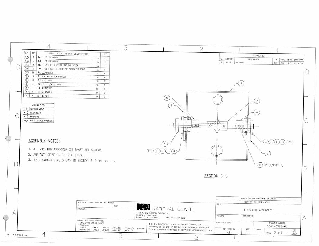

www.nov.com
Spare Parts List
REFERENCE
1100012 REFERENCE DESCRIPTION
IR3080 Iron Roughneck, 88" Arm This document contains proprietary and confidential information which is the property of National Oilwell Varco, L.P., its affiliates or subsidiaries (all collectively referred to hereinafter as "NOV"). It is loaned for limited purposes only and remains the property of NOV. Reproduction, in whole or in part, or use of this design or distribution of this information to others is not permitted without the express written consent of NOV. This document is to be returned to NOV upon request or upon completion of the use for which it was loaned. This document and the information contained and represented herein is the copyrighted property of NOV.
© National Oilwell Varco
National Oilwell Varco RIG SOLUTIONS
12950 West Little York Houston, TX 77041
DOCUMENT NUMBER
D811000104-SPL-001 REV
01
IR3080 Iron Roughneck, 88" Arm

Document number D811000104-SPL-001 Revision 01 Page 2
www.nov.com
REVISION HISTORY
01 11/28/2007 First Issue BMD BMD KS Rev Date (dd.mm.yyyy) Reason for issue Prepared Checked Approved
CHANGE DESCRIPTION
Revision Change Description 01 First issue

Document number D811000104-SPL-001 Revision 01 Page 3
www.nov.com
1 SPARE PARTS LIST This document provides a list of recommended spares. The list is presented by assemblies, and the recommended spare pages are arranged in numerical order.
2 DEFINITIONS This section provides definitions for part classifications, accessibility of spare parts, and recommendations of spare parts.
2.1 Part Classification
Part Class Part Type Part Description Class A Maintenance
Items Expendable items requiring periodic service or replacement.
Class B Repair Items Wearing parts, which normally have an extended, but not indefinite life.
Class C Major Repair Items
Parts ordinarily replaced only during major overhaul.
2.2 Spare Parts Accessibility
Spares Category
Definition
Area 1 Equipment operating within easy access to a National Oilwell Varco store or customer’s own regional warehouse and expendable parts anticipated for operation of one year.
Area 2 Equipment operating in remote areas.
Group I Spares for one unit per year.
Group II Spares to support up to two units operating in the area per year.
2.3 Recommendations
Operations Recommendations Equipment in accessible Area 1
1 Lot of Spares for each unit.
Equipment in accessible Area 2
1 Lot of Group I Spares for each unit per year, OR 1 Lot of Group II Spares for approximately each 2 units
2-3 years operations
Multiply Class A spares by 2.

Document number D811000104-SPL-001 Revision 01 Page 4
www.nov.com
This page intentionally left blank.

Document number D811000104-SPL-001 Revision 01 Page 5
www.nov.com
SPARE PARTS LIST Subject IR3080 Iron Roughneck, 88" Arm
Date
11/28/2007
Prepared
B. Dominguez
Approved
B. Winter
Assembly Drawing Number
1100012 Rev
B
Document No. Assembly Description
Assemblies
1100012-RSP IRON ROUGHNECK ASSEMBLY 1 1100154-RSP WRENCH ASSEMBLY 1 1100189-RSP SPINNER ASSEMBLY 1 AR03-03-01-RSP UPPER-RIGHT LINK ASSEMBLY 1 AR03-03-02-RSP LOWER-RIGHT LINK ASSEMBLY 1 AR03-03-03-RSP LOWER-LEFT LINK ASSEMBLY 1 AR03-03-04-RSP SINGLE RIGHT ARM 1 AR03-03-05-RSP SINGLE LEFT ARM 1 AR06-RSP ARM ASSEMBLY 1 AR06-03-RSP LINK ASSEMBLY 1 AR06-07A-RSP GUIDE ASSEMBLY 1 AR06-08-RSP COLUMN ASSEMBLY 1 LS02-RSP LIFTING SKID ASSEMBLY 1 SPAR-0403-52 IR REMOTE CONTROL CONSOLE 1 SPAR-0403-53 IR ELECTRO-HYDRAULIC ASSEMBLY 1 SPAR-0365-61 ERLS J-BOX 1


![Don$Robinson,$PE$$ VPDrilling$ Canonsburg,$PA$ 1on$iron$roughneck,$kelly$ hose$and$top$drive.$ * 0.0 10.0 20.0 30.0 ... 1st$Iden]fy$the$Cri] ... vity$Improvementfrom$2010$to$2012$=$](https://img.dokumen.tips/doc/110x75/5b1f9b407f8b9ab9748b6056/donrobinsonpe-vpdrilling-canonsburgpa-1-onironroughneckkelly-hoseandtopdrive.jpg)