Embed Size (px)
Citation preview
Hindawi Publishing CorporationEURASIP Journal on Advances in Signal ProcessingVolume 2007, Article ID 36751, 12 pagesdoi:10.1155/2007/36751
Research ArticleIris Recognition for Partially Occluded Images:Methodology and Sensitivity Analysis
A. Poursaberi1 and B. N. Araabi1, 2
1 Department of Electrical and Computer Engineering, Control and Intelligent Processing Center of Excellence,Faculty of Engineering, University of Tehran, P.O. Box 14395-515, Tehran, Iran
2 School of Cognitive Sciences, Institute for Studies in Theoretical Physics and Mathematics, P.O. Box 19395-5746, Tehran, Iran
Received 17 March 2005; Revised 12 January 2006; Accepted 15 March 2006
Recommended by Wilfried Philips
Accurate iris detection is a crucial part of an iris recognition system. One of the main issues in iris segmentation is coping withocclusion that happens due to eyelids and eyelashes. In the literature, some various methods have been suggested to solve theocclusion problem. In this paper, two different segmentations of iris are presented. In the first algorithm, a circle is located aroundthe pupil with an appropriate diameter. The iris area encircled by the circular boundary is used for recognition purposes then.In the second method, again a circle is located around the pupil with a larger diameter. This time, however, only the lower partof the encircled iris area is utilized for individual recognition. Wavelet-based texture features are used in the process. Hammingand harmonic mean distance classifiers are exploited as a mixed classifier in suggested algorithm. It is observed that relying ona smaller but more reliable part of the iris, though reducing the net amount of information, improves the overall performance.Experimental results on CASIA database show that our method has a promising performance with an accuracy of 99.31%. Thesensitivity of the proposed method is analyzed versus contrast, illumination, and noise as well, where lower sensitivity to all factorsis observed when the lower half of the iris is used for recognition.
Copyright © 2007 Hindawi Publishing Corporation. All rights reserved.
1. INTRODUCTION
Security and surveillance of information is becoming moreand more important recently, in part due to the rapid de-velopment of information technology (IT) applications. Thesecurity not only includes the information but also containsthe people who access the information. Other applications ofsecurity systems such as allowing authorized person to entera restricted place, individual identification/verification, andso forth also cover a wide range of the market. Traditionalmethods for personal identification include things you cancarry, such as keys, or things that you know. ID cards or keyscan be lost, stolen, or duplicated. The same may happen forpasswords or personal identification numbers. All kinds ofthese means are not very reliable. Hence, biometrics comesout to overcome these defects. Biometrics is the science ofrecognizing a person based on physical or behavioral charac-teristics. Biometrics description on who you are depends onone of any number of unique characteristics that you cannotlose or forget [1, 2]. Fingerprints, voiceprints, retinal bloodvessel patterns, face, handwriting, and so forth can be substi-tuted instead of nonbiometric methods for more safety and
reliability. Among these biometric characteristics, a finger-print needs physical contact and also can be captured or im-itated. Voiceprint in a like manner can easily be stored. As anew branch of biometrics, iris recognition shows more satis-factory performance. The human iris is the annular part be-tween the pupil and the sclera, and has distinct characteristicssuch as freckles, coronas, stripes, furrows, crypts, and so on.Compared with other biometric features, personal authenti-cation based on iris recognition can attain high accuracy dueto the rich texture of iris patterns [1–3]. Users of iris recog-nition system neither have to remember any passwords norhave any cards. Due to no requirement of touching for imagecapturing, this process is more convenient than the others.
Iris (as shown in Figure 1) is like a diaphragm betweenthe pupil and the sclera and its function is to control theamount of light entering through the pupil. Iris is composedof elastic connective tissue such as trabecular meshwork. Theiris begins to be formed in the third month of gestation,and the structures creating its pattern are largely complete bythe eighth month. The agglomeration of pigment is formedduring the first year of life, and pigmentation of the stromaoccurs in the first few years [4]. The highly randomized
2 EURASIP Journal on Advances in Signal Processing
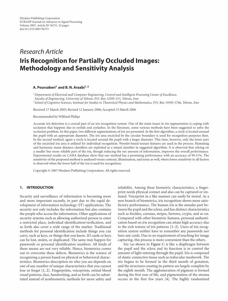
Figure 1: Samples of iris.
appearance of the iris makes its use as a biometric well rec-ognized. Its suitability as an exceptionally accurate biometricderives from
(i) the difficulty of forging and using as an imposter per-son;
(ii) its intrinsic isolation and protection from the externalenvironment;
(iii) its extremely data-rich physical structure;(iv) its genetic properties—no two eyes are the same. The
characteristic that is dependent on genetics is the pig-mentation of the iris, which determines its color anddetermines the gross anatomy. Details of development,that are unique to each case, determine the detailedmorphology;
(v) its stability over time;(vi) the impossibility of surgically modifying it without
unacceptable risk to vision and its physiological re-sponse to light, which provides a natural test againstartifice.
An automatic iris recognition system includes three mainsteps:
(i) preprocessing such as image acquisition, iris localiza-tion, iris normalization, iris denoising, and enhance-ment;
(ii) iris feature extraction;(iii) iris feature classification.
1.1. Outline of the paper
In the sequel, we first bring a history of related works inbrief. An overview of our proposed algorithm is presentedin Section 2, which provides a conceptual overview of ourmethod based on an intuitive understanding for iris recog-nition system. Detailed descriptions of image preprocessing,feature extraction, and pattern matching for proposed al-gorithms are given in Sections 3, 4, and 5, respectively. InSection 6, sensitivity of our method versus contrast, illumi-nation, and noise is analyzed. Experimental results on an irisdatabase is reported in Section 7. Finally, the paper is con-cluded in Section 8, where the obtained results are summa-rized and the advantages of the proposed method are empha-sized.
1.2. Related works
First works in iris recognition techniques were reported thelate 19th century [3, 5] but most works are done in the lastdecade. Daugman [6, 7] used multiscale quadrature waveletsto extract texture phase structure information of the iris togenerate a 2048-bit iris code and he compared the differ-ence between a pair of iris representations by computingtheir Hamming distance. He showed that for identification,it is enough to have a lower than 0.34 Hamming distancewith any of the iris templates in database. Ma et al. [8–10]adopted a well-known texture analysis method (multichan-nel Gabor filtering) to capture both global and local detailsin iris. They studied well Gabor filter families for feature ex-traction in some papers. Wildes et al. [11] with a Laplacianpyramid constructed in four different resolution levels andthe normalized correlation for matching designed their sys-tem. Boles and Boashash [12] used a zero-crossing of 1Dwavelet at various resolution levels to distinguish the tex-ture of iris. Tisse et al. [13] constructed the analytic image(a combination of the original image and its Hilbert trans-form) to demodulate the iris texture. Lim et al. [14] used2D Haar wavelet and quantized the 4th-level high-frequencyinformation to form an 87-binary code length as featurevector and applied an LVQ neural network for classifica-tion. Nam et al. [15] exploited a scale-space filtering to ex-tract unique features that use the direction of concavity ofan image from an iris image. Using sharp variations pointsin iris was represented by Ma et al. [16]. They constructedone-dimensional intensity signal and used a particular classof wavelets with vector of position sequence of local sharpvariations points as features. Sanchez-Reillo and Sanchez-Avila in [17] provided a partial implementation of the al-gorithm by Daugman. Also their other work on developingthe method of Boles and Boashash by using different dis-tance measures (such as Euclidean distance and Hammingdistance) for matching was reported in [18]. A modified Har-alick’s co-occurrence method with multilayer perceptron isalso introduced for extraction and classification of the iris[19, 20]. Park et al. [21] used a directional filter bank to de-compose iris image into eight directional subband outputsand the normalized directional energy as features. Kumar etal. [22] utilized correlation filters to measure the consistencyof iris images from the same eye. The correlation filter of eachclass was designed using the two-dimensional Fourier trans-forms of training images. Bae et al. [23] projected the irissignals onto a bank of basis vectors derived by independentcomponent analysis and quantized the resulting projectioncoefficients as features. Gu et al. [24] used a multiorientationfeatures via both spatial and frequency domains and a non-symmetrical SVM to develop their system. They extractedfeatures by variant fractal dimensions and steerable pyramidsfor orientation information.
We compare the benefits and drawbacks of some dom-inant works done by the others with our works in Table 1.The kind of features, matching strategy, and their results arementioned and also we are going to overcome the commonproblems in most of the previous methods: occlusion.

A. Poursaberi and B. N. Araabi 3
Table 1: The comparison of methods.
Methods Matching process Kind of feature Result + benefits
Hamming distance BinaryPerfect identification + and can overcome the
Daugman [6]occlusions problem but time wasting
Normalized correlation ImageTime wasting in matching process. It
can be used only in identificationWildes et al. [11]
phase not recognition
Two dissimilarity functions:learning and classification
1D signatureNot complete recognition rate, high
EER, fast process time, simple 1DBoles and Boashash [12]
feature vector, fast processing
Nearest feature line1D real-valued feature vectorwith the length of 384
Time wasting in feature extraction, cannotTan et al. [8]
cope with occlusions problem
Weighted Euclideandistance
1D real-valued feature vectorwith the length of 160
Big EER, poor recognition rate, cannotMa et al. [10]
cope with occlusions problem
XOR operation1D integer-valued feature vectorwith the length of 660
Improved last their works, good recognition
rate, claims 100% correct recognition,
cannot overcome the occlusions ofMa et al. [16]
upper eyelid and eyelashes
Sanchez-ReilloEuclidean and Hammingdistances
1D signatureMedium classification rate, cannot
and Sanchez-Avila cope with occlusions problem,
[17] simple 1D features
LVQ neural network 1D binary vectorPoor recognition rate, complicated classifier,
Lim et al. [14]big EER, occlusions problem
Previous [25, 26] Hamming distance408 and 1088 binarymatrices (2 papers)
Simple low-dimensional binary features,
can cope with occlusions in lower case
(eyelid and eyelashes), medium recognition rate,
fast processing, not engaging with edge detection
Proposed
Complex classifier(joint of Hammingdistance of minimumand harmonic mean)
544 binary matrix
Not engaging with edge detection which is
time wasting and not accurate as iris is not
a complete circle-shape, can conquer the
occlusions in both upper and lower cases,
simple and short feature length, fast processing
2. AN OVERVIEW OF THE PROPOSED APPROACH
In this paper, to implement an automatic iris recognitionsystem, we propose a new algorithm in both iris detectionand feature extraction modes. Using morphological oper-ators for pupil detection and selecting the appropriate ra-dius around the pupil to pick the region of iris which con-tains the collarette—that appears as a zigzag pattern—arethe main contributions of the paper. This region provides aunique textual pattern for feature extraction. Selected coeffi-cients of 4-level and 3-level Daubechies wavelet decomposi-tions of iris images are chosen to generate a feature vector. Tosave the storage space and computational time for manipu-lating the feature vector, we quantize each real value into bi-nary value using merely its sign disregarding its magnitude.A typical iris recognition system includes some major stepsas depicted in Figure 2. At first, an imaging system must bedesigned to capture a sequence of iris images from the sub-ject in front of camera. A comprehensive study is done in[27, 28]. The next step is choosing a clear image from the
sequence of captured images. A good iris quality assessmentbased on Fourier spectra analysis was suggested in [9]. Af-ter selecting the high-quality image, with morphological im-age processing operators, the edge of the pupil is determined[29].
A brief overview of the method is as follows:
(i) filling the holes which are pseudocreated by the lightreflection on the cornea or further in eye;
(ii) enhancing the contrast of image by adjusting image in-tensity;
(iii) finding the “regional minima.” Regional minima areconnected components of pixels with the same inten-sity value, T , whose external boundary pixels all havea value greater than T ;
(iv) applying morphological operators. The operation isrepeated until the image no longer changes and sets apixel to 1 if five or more pixels in its 3-by-3 neighbor-hood are 1’s; otherwise, it sets the pixel to 0 in a binaryimage from the previous step;

4 EURASIP Journal on Advances in Signal Processing
Pu
pill
ocal
izat
ion
+ir
isse
gmen
tati
on
Iris
nor
mal
izat
ion
Normalized iris Enhanced +denoised irisimage
Feat
ure
extr
acti
on Feature
Mat
chin
g
Sele
ctin
gth
em
inim
um
dist
ance
from
vari
ous
angl
es
15 12 9 6 3 0 3 6 9 12 15
???????????
Figure 2: Flowchart of automatic iris recognition system.
(v) removing the small connected parts in image whichtheir areas are less than a threshold.
The pupil now is well detected and its center and radiusare gotten. We can also obtain the edge of iris that is men-tioned in our previous work [29]. The advantage of this kindof edge detection is its speed and good performance becausein morphological processing, we deal with binary images andprocessing on binary images is very fast. After pupil detec-tion, with trial and error, we get that by choosing an appro-priate radius as the outer boundary of iris, the selected re-gion by this threshold contains the collarette structure well.Preprocessing on the selected iris region is the next step thatincludes iris normalization, iris image enhancement and de-noising.
3. IMAGE PREPROCESSING
This step contains three substages. A captured image con-tains not only the iris but also some parts such as eyelid,eyelash, pupil, and sclera which are not desirable. Distancebetween camera and eye and environmental light conditions(dilation of pupil) can influence the size of the iris. Therefore,before the feature extraction step, the image must be prepro-cessed to overcome these problems. These substages are asfollows. In our system, we use 320× 280 grayscale images.
3.1. Iris localization
Iris boundaries can be supposed as two nonconcentric cir-cles. We must determine the inner and outer boundaries withtheir relevant radius and centers. Several approaches con-cerning iris edge detection were proposed. Our method isbased on iris localization by using image morphological op-erators and suitable threshold [29]. The summary method is
as follows:
(i) evaluating the complement of the image (the absolutesubtraction of each pixel’s intensity from 255);
(ii) filling holes in the intensity image. A hole is anarea of dark pixels surrounded by lighter pixels. Weused 4-connected background neighbors for inputimages which mean a neighborhood whose neigh-bors are touching the central element on an (N −1)-dimensional surface, for the N-dimensional case(N = 2);
(iii) evaluating again the complement of the processed im-age;
The pupil edge detection is obtained from the prepro-cessed iris image in the above process. By a suitable thresholdand the strategy stated below, the edge of pupil is detected.
(i) Select two appropriate numbers for upper and lowerthresholds L,U . L (in the range of [0 1]) determinesthe detected circle quality. If the parameter L increasesto 1, the quality of detected circle decreases and viceversa. U is adjusted to reject small points as a circle.If U increases (from 1 to infinity), only the large circlewill be detected and for acceptance all points as a circle,it must be adjusted to 1.
(ii) For K = 1 iteration number, do as follows:
(1) see the intensity of each pixel, if it is lower thanL+K , convert it to 0 and if it is bigger than U−K ,covert it to 255;
(2) otherwise, filter the intensity to the lower one bya scaling factor.
(iii) The processed image is converted to a logical imagewhich means that a black-and-white-type image willbe obtained.

A. Poursaberi and B. N. Araabi 5
For the pupil, in edge detection via morphology oper-ators, maybe some other parts have been detected. Hence,these artifacts must be detected and withdrawn by the pro-cess. The algorithm of computing coordinates and radiusesof the resulted image is as follows:
(i) performing morphological operations (clean, spur,and fill) on binary image to remove the mentioned ar-tifacts;
(ii) labeling the connected components of the image (n) inthe above step. Repeat the below process from i = 1ntimes to locate circles among the components:
(1) find the labeled image’s pixels that are equal to i.Determine the size of the found component,
(2) conceptually, a square is located around eachcomponent, and then the closed feature is com-pared with a circle occupying the surroundedsquare,
(3) if it can satisfy the conditions of similarity toa circle, then the feature that is surrounded bysquare is labeled as a circle. These conditionsare related to thresholds L and U , the compar-ison between obtained component and the cir-cle which can be surrounded by the square, andcomparison of the ratio of row against columnpixels with a threshold,
(4) the coordinate and radius of the obtained cir-cle are calculated easily by the size of the locatedsquare.
As mentioned earlier, after pupil edge detection (innerboundary), the outer boundary is the edge of a circle with aradius of ri = 28 + rp. In our second algorithm, the edge of acircle with a radius of ri = 38 + rp is captured and the lowerpart of this circle is our desired region. With trial and error,we get that by choosing a radius of 28 pixels from the edge ofthe pupil, the selected region usually contains the collarettestructure well. This region has abundant features of iris op-posite to the other parts.
3.2. Iris normalization
Different image acquisition conditions influence and disturbthe process of identification. The dimensional incongruitiesbetween eye images are mostly due to the stretching of the iriscaused by pupil expansion/ contraction from variation of theilluminations and other factors. Other circumstances includevariance of camera and eye distance, rotation of the cameraor head. Hence, a solution must be contrived to remove thesedeformations. The normalization process projects iris regioninto a constant-dimensional ribbon so that two images of thesame iris under different conditions have characteristic fea-tures at the same spatial location. Daugman [6, 7, 30] sug-gested a normal Cartesian-to-polar transform that remapseach pixel in the iris area into a pair of polar coordinates(r, θ), where r and θ are on the intervals [0 1] and [0 2π],respectively. This unwrapping is formulated as follows:
I(x(r, θ), y(r, θ)
) −→ I(r, θ) (1)
such that
x(r, θ) = (1− r)xp(θ) + rxl(θ),
y(r, θ) = (1− r)yp(θ) + r yl(θ),(2)
where I(x, y), (x, y), (r, θ), (xp, yp), (xi, yi) are the iris re-gion, Cartesian coordinates, corresponding polar coordi-nates, coordinates of the pupil, and iris boundaries alongthe θ direction, respectively. This representation (the rubbersheet model) removes the above-mentioned deformations.We performed this method for normalization and selected64 pixels along r and 512 pixels along θ and got a 512 × 64unwrapped strip. On account of asymmetry of pupil (not be-ing a circle perfectly) and probability of overlapping outerboundaries with sclera or eyelids in some cases and due tothe safely chosen radius around the pupil, in the second al-gorithm we select 3 to 50 pixels from 64 pixels along r and257 to 512 pixels from 512 pixels along θ in unwrapped iris.The normalization not only reduces exactly the distortion ofthe iris caused by pupil movement, but also simplifies subse-quent processing.
3.3. Iris denoising and enhancement
On account of imaging conditions and situations of lightsources, the normalized iris image does not have an appro-priate quality. These factors may affect the performance offeature extraction and matching processes. Hence for get-ting a uniform distributed illumination and better contrastin iris image, we first equalize the intensity of pixels in un-wrapped iris image and then filter it with an adaptive lowpassWiener2D filter to remove high-frequency noises. Wiener2Dis a lowpass filter that filters an intensity image which hasbeen degraded by constant power additive noise. It uses apixelwise adaptive Wiener method based on statistics es-timated from a local neighborhood of each pixel. In ourmethod, the size of neighborhoods is 5 × 5. Wiener2D es-timates the local mean and variance around each pixel as fol-lows:
μ = 1MN
∑
n1,n2∈ηa(n1, n2
),
σ2 = 1MN
∑
n1,n2∈ηa2(n1, n2
)− μ2,
(3)
where η is the N-by-M local neighborhood of each pixel inthe image. The filter then creates a pixelwise Wiener filter us-ing the following estimates:
b(n1, n2
) = μ +σ2 − v2
σ2
(a(n1, n2
)− μ), (4)
where v2 is the noise variance. If the noise variance is notgiven, it uses the average of all the local estimated variances.In the first mode, we used all of the projected iris area and inthe second mode, the right part of the unwrapped iris whichindicates the lower part of segmented iris is used. The wholepreprocessing stages for the two algorithms are depicted inFigures 3 and 4, respectively.

6 EURASIP Journal on Advances in Signal Processing
(a) (b)
(c)
(d)
Figure 3: (a) Original image; (b) localized iris; (c) normalized iris;and (d) enhanced iris.
4. FEATURE EXTRACTION
The most important step in automatic iris recognition is theability of extracting some unique attributes from iris whichhelp to generate a specific code for each individual. Gaborand wavelet transforms are typically used for analyzing thehuman iris patterns and extracting features from them [6–10, 14, 30].
In our earlier work [31], which we have used all irisregions (may contain eyelid/eyelash), wavelet Daubechies2have been applied to iris. Now by new segmentation of theiris region as mentioned above, we applied the same wavelet.The results show that on account of not including the uselessregions in the limited iris boundary, the identification rateis improved well. In Figure 5(a), a conceptual chart of ba-sic decomposition steps for images is depicted. The approxi-mation coefficients matrix cA and details coefficients matri-ces cH, cV, and cD (horizontal, vertical, and diagonal, resp.)obtained by wavelet decomposition of the input image areshown in Figure 5(b). The definitions used in the chart are asfollows.
(i) C ↓ denote downsample columns—keep the even-indexed columns.
(ii) D ↓ denote downsample rows—keep the even-indexedrows.
(iii) Lowpass D denotes the decomposition lowpass filter.(iv) Highpass D denotes the decomposition highpass filter.(v) The blocks under “Rows” convolve with filter of block
the rows of entry.(vi) The blocks under “Columns” convolve with filter of
block the columns of entry.(vii) Ii denotes the input image.
In the first algorithm, we got the 4-level wavelet de-composition details and approximation coefficients of un-wrapped iris image and in the second one, the 3-level was
(a) (b)
Pupil asymmetry
Eyelid occlusion
(c)
(d)
Region of interest
(e)
Figure 4: (a) Original image; (b) localized iris; (c) normalized iris;(d) enhanced iris; and (e) region of interest.
chosen. Since our unwrapped image has a size of 512 ×64 (256 × 48) pixels, after 4(3) times decompositions, thesize of last part is 6 × 34 (8 × 34). We arranged our fea-ture vector by combining 408 = ([6× 34 6× 34]) featuresin the LH and HL of level-4 (vertical and horizontal ap-proximation coefficients [LH4 HL4]) in the first algorithm
and 544 = ([8× 34 8× 34]) in the second algorithm. Thenbased on the sign of each entry, we assign +1 to the posi-tive entry of feature vector and 0 to others. Finally, we built a408(544) binary feature vector (FV). The two typical featurevectors are shown in Figure 6.
5. CLASSIFICATION
In classification stage, by comparing the similarity betweencorresponding feature vectors of two irises, we can determinewhether they are from the same class or not. Since the featurevector is binary, the matching process will be fast and simpleaccordingly. We perform two classifiers based on minimumHamming distance (MHD):
HD = XOR (codeA, codeB), (5)
where codeA and codeB are the templates of two images.It is desirable to obtain an iris representation invariant totranslation, scale, and rotation. In our algorithm, transla-tion and scale invariance are achieved by normalizing the

A. Poursaberi and B. N. Araabi 7
Lowpass D
Highpass D
C
C
Rows Columns
Highpass D
Lowpass D
Highpass D
Lowpass D D
D
D
D
cA
cH
cV
cD
Wavelet decomposition levels
i + 1I j
(a)
LH3
HH3HL3
LH2
LH1
HH2HL2
HL1 HH1
512
64
6
34
(b)
Figure 5: (a) Wavelet decomposition steps diagram and (b) 4-level decomposition of a typical image with a db2 wavelet.
(a)
(b)
Figure 6: Two typical feature vectors (a) in the first algorithm withthe size of 408 and (b) in the second algorithm with the size of 1088.
original image at the preprocessing step. Most rotation in-variance methods which are suggested in related papersare achieved by rotating the feature vector before match-ing [6, 7, 12, 13, 17, 30], and Wildes did it by registeringthe input image with the model before feature extraction[11]. Since features in our method are the selected coeffi-cients of decomposition levels which are gotten via wavelet,
there is no explicit relation between features and the origi-nal image. Therefore, rotation in the original image corre-sponds to translation in the normalized image [8, 9, 16].We obtain approximate rotation invariance by unwrappingto different initial angles. Considering that the eye rotationis not very large in practical applications, these initial an-gle values are chosen from −15◦ to 15◦ with steps of threedegrees. This means that we define eleven templates whichdenote the eleven rotation angles for each iris class in thedatabase. Matching the input feature vector with the tem-plates of an iris class means that the minima of these elevendistances are selected as the result. When an iris image is cap-tured in system, the designed classifier compares it with thewhole images in each class (depending on the total imagesfor every one). The Hamming distances (HDs) between in-put image and images in each class are calculated then twodifferent classifiers are being applied as follows.
(i) In the first classifier, the minimum HD between inputiris code and codes of each class is computed as follows:

8 EURASIP Journal on Advances in Signal Processing
Table 2: Results of illumination test conditions.
Increasing 25 40 60 70 60 80 90 95Changes in increasing No No No No No No 1 fails 3 failsDecreasing 25 40 60 70 100 120 130 —Changes in decreasing No No No No No 1 fails 5 fails —
(1) for each image of class, the HDs between inputcode and its eleven related codes are computed.Finally the minimum of them is recorded;
(2) if we have n images in each class, the minimumof these n HDs is assigned to the class.
(ii) In the second classifier, the harmonic mean of the nHDs which have been recorded yet is assigned to theclass. The harmonic mean formula is as follows:
HM = length(code)∑length(code)
i=1 (1/code(i)). (6)
Accordingly, when we sort the results of two classifiersin an ascending order, each class is labeled with its relateddistance and we call them SHD and SHM, respectively. Evenif one of the first two numbers of SHD or SHM denotes tocorrect class, the goal is achieved. It will be correct if thenumber is less that the threshold which will be selected basedon the overlap of the FAR and FRR plots. Input iris imagesafter coding are compared with all iris codes which exist indatabase. Identification and verification modes are two maingoals of every security system based on the needs of the en-vironment. In the verification stage, the system checks if theuser data that was entered is correct or not (e.g., usernameand password) but in the identification stage, the system triesto discover who the subject is without any input information.Hence, verification is a one-to-one search but identification isa one-to-many comparison. This system has been tested inboth modes.
6. SENSITIVITY ANALYSIS
As mentioned above by normalizing iris images, scale andsize invariant are obtained but other factors can influence thesystem process. We performed on the second method (half-eye) the sensitivity analysis with three major of them whichwill be detailed as follows. The input images are the same asin the experimental results and the method of classificationis the same as the proposed algorithm, too.
6.1. Illumination
Due to the position of light sources in the various image cap-turing conditions, the brightness of images may be changed.These changes can damage the process of recognition if fea-ture extraction has a high correlation with them. We per-formed some various conditions. The test conditions areshown in Table 2. By increasing (decreasing) the brightnessof iris region and testing these deformed images as an inputto the system and calculating their distances, it was achieved
that our feature extraction is a highly illumination invariant.Figures 7(a) and 7(b) show the effect of variance of illumina-tion on distance in two increasing and decreasing ways.
6.2. Contrast
Based on the distribution of image intensities, the contrastof picture is variable. It seems that contrast may be an im-portant factor for the process of recognition. We tested somemodes by varying the iris region contrast so that the intensityof an input image was lower than the original image. The re-sults showed that our feature extraction is highly robust ver-sus the variation of contrast. Figure 8(a) represents effect ofvariance of contrast on the distance of a matching process.Typically for an input iris image, the bounds of histogramfor five testing image conditions are shown in Figure 8(b).
6.3. Noise
A fundamental factor which must be considered to designany system is the effect of environment’s noises on efficiencyof system. Due to the subject of security, being noise invari-ant is crucial. We have tested two kinds of noises in two dif-ferent modes. The first mode is applying noise to all imagesby constant variance and checking identification process. Thesecond mode is applying variable noise for every input im-age. In the second mode, each image is affected by noisewith different characteristics which this mode includes var-ious kinds of alike class noise. Gaussian and Salt and Peppernoises are considered for testing because Gaussian is a popu-lar noise for testing the robustness of most systems and Saltand Pepper noise is composed of random pixels which candestroy the iris region by inserting the black or white pix-els and it is the extreme mode of altering. In the Gaussianmode, we created noise by multiplying a constant by a ran-dom function and increased the constant in each trial from0 to 10 with step size equal to 2 and repeated this five timesdue to the randomness of noise. We get that until constantless than 6, there is no false more than usual conditions butwhen increased to 8 and 10, the number of added fails in-creased linearly.
In Salt and Pepper mode, although this kind of noises se-riously damage the image, experiments showed that recog-nition success rate did not change more. It means that byincreasing the noise area from 0% to 10% of the whole irisregion (randomly 50% Salt and 50% Pepper), in average 3fails for less than 0.06 and the maximum 8 fails for the addednoise with the variance of 0.1 taking place. In Figures 9(a)and 9(b), the performance of verification in two noisy con-ditions are shown.

A. Poursaberi and B. N. Araabi 9
1 29 57 85 113 141 169 197 225 253 281 309 337 365 3930
0.05
0.1
0.15
0.2
0.25
0.3
0.35
0.4
Dis
tan
ce
Counts
0.10.30.5
0.70.9
The distribution of distances of decreasing contrast
(a)
1 29 57 85 113 141 169 197 225 253 281 309 337 365 3930
0.05
0.1
0.15
0.2
0.25
0.3
0.35
0.4
Dis
tan
ce
Counts
�25�40�60�70
�100�120�130
The distribution of distances of decreasing illumination
(b)
Figure 7: The results of the illumination changing: (a) increasing and (b) decreasing. The upper bounds of increased (decreased) testconditions do not exceed the maximum tradeoff threshold.
1 29 57 85 113 141 169 197 225 253 281 309 337 365 3930
0.05
0.1
0.15
0.2
0.25
0.3
0.35
0.4
Dis
tan
ce
Counts
0.10.30.5
0.70.9
The distribution of distances of decreasing contrast
(a)
0 0.1 0.2 0.3 0.4 0.5 0.6 0.7 0.8 0.9 1
0
1
2
3
4
5
6�103
0.10.30.5
0.70.9Original
The histogram of a typical iris image undervarious test set reduces-contrst modes
(b)
Figure 8: (a) The result of the contsrat changing and (b) the bounds of five test conditions in contrast reduction for a typically sample image.
7. EXPERIMENTAL RESULTS
To evaluate the performance of the proposed algorithm, wetested our alghoritm on CASIA version 1 database. Unlikefingerprints and face, there is no reasonably sized public-domain iris database. The Chinese Academy of Sciences,Institute of Automation (CASIA) eye image database [32]
contains 756 greyscale eye images with 108 unique is notclear we recommend to have this figure printed in colors,in which case the authors or their eyes or classes and 7 dif-ferent images of each unique eye. Images from each classare taken from two sessions with one month interval be-tween sessions. The images were captured [10] specially foriris recognition research using specialized digital optics—

10 EURASIP Journal on Advances in Signal Processing
0 5 10 15 20 25 30
The variance of Gaussian noise
0
10
20
30
40
50
60
70
80
90
100
Nu
mbe
rof
fals
em
atch
adde
d
0 2 4 6 8 100
2
4
6
(a)
0 0.05 0.1 0.15 0.2 0.25 0.3 0.35 0.4
Density of added noise (�100%)
0
10
20
30
40
50
60
Nu
mbe
rof
fals
em
atch
adde
d
0 0.02 0.04 0.06 0.08 0.10
2
4
6
8
(b)
Figure 9: The performance of system under two kinds of noises: (a) the result of Gaussian noise adding and (b) the result of Salt & peppernoise adding. The results showed that under the reasonable noisy conditions, the captured images will be recognized well with a little bitsmaller success rate.
10�3 10�2 10�1 100 101
False match rate (%)
0
1
2
3
4
5
6
7
Fals
en
onm
atch
rate
(%)
FirstSecond
ROC plot
(a)
0.1 0.15 0.2 0.25 0.3 0.35 0.4 0.45 0.5 0.55 0.6
Normalized matching distance
0
0.05
0.1
0.15
0.2
0.25
0.3
0.35
Den
sity
Normalized intraclass distributionNormalized interclass distribution
Distribution of classes
(b)
Figure 10: (a) The verification results of two proposed methods and (b) the distribution of intraclass and interclass distances. The feweroverlap results, the better recognition results.
a homemade digital camera which used to capture the irisdatabase—developed by the National Laboratory of PatternRecognition, China. The eye images are mainly from per-sons of Asian decent, whose eyes are characterized by irisesthat are densely pigmented, and with dark eyelashes. Due tospecialized imaging conditions using near-infrared light, fea-tures in the iris region are highly visible and there is goodcontrast between pupil, iris, and sclera regions. For each irisclass, we choose three samples taken at the first session fortraining and all samples captured at the second session serveas test samples. This is also consistent with the widely ac-cepted standard for biometrics algorithm testing [33, 34].
We tested the proposed algorithms in two modes: (1)identification and (2) verification. In identification tests, anaverage correct classification rate of the first algorithm was97.22% and 99.31% was achieved in the second algorithm.The verification results are shown in Figure 10(a) which is
the ROC curve of the proposed method. It is the false non-match rate (FNMR) versus false match rate (FMR) curvewhich measures the accuracy of the iris matching processand shows the overall performance of an algorithm. Pointsin this curve denote all the possible system operating statesin different tradeoffs. The EER is the point where the falsematch rate and the false nonmatch rate are equal in value.The smaller the EER (which is dependent directly on FMRand FNMR and its smaller value with regard to the smallervalues of FMR and FNMR intersection) is, the better the al-gorithm is [16]. EER is about 1.0334% and 0.2687 in twosuggested methods, respectively. Figure 10(b) shows the dis-tribution of intraclass and interclass matching distances ofthe second algorithm. Three typical system operating statesof the second proposed method are listed in Table 3.
We analyzed the images that failed in the process andrealized that all of the images are damaged mainly with
A. Poursaberi and B. N. Araabi 11
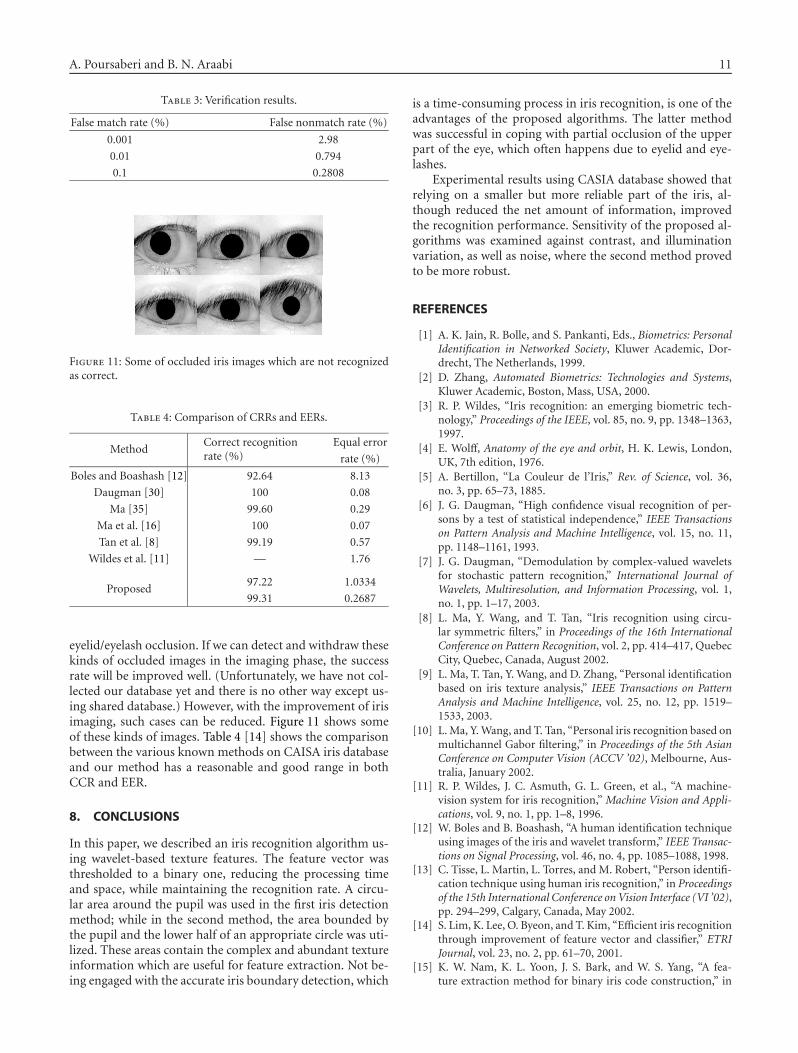
Table 3: Verification results.
False match rate (%) False nonmatch rate (%)
0.001 2.98
0.01 0.794
0.1 0.2808
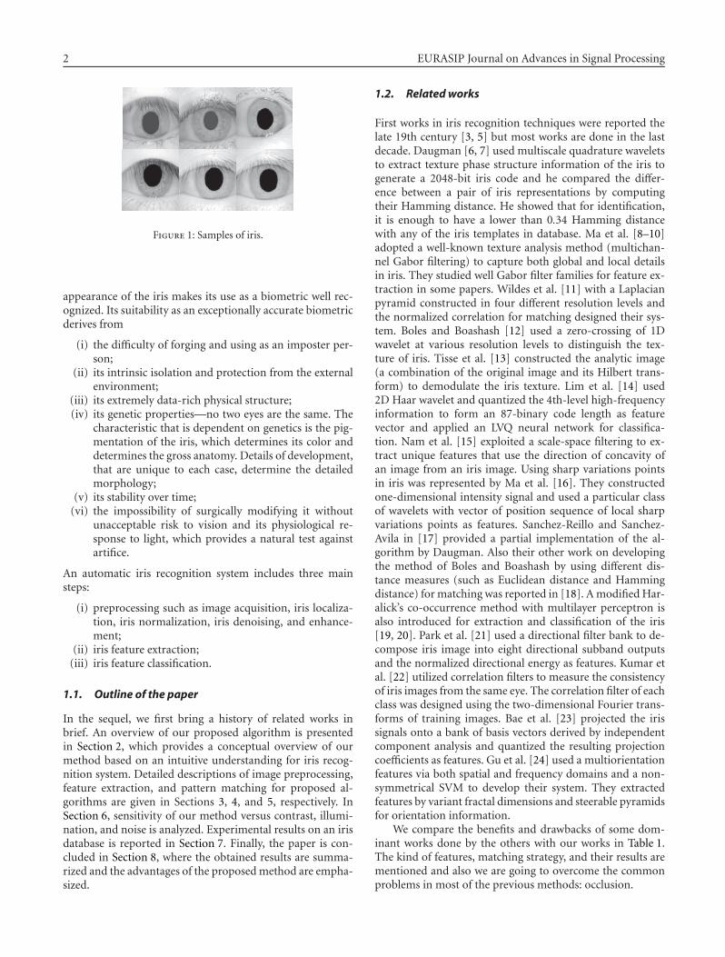
Figure 11: Some of occluded iris images which are not recognizedas correct.
Table 4: Comparison of CRRs and EERs.
MethodCorrect recognitionrate (%)
Equal error
rate (%)
Boles and Boashash [12] 92.64 8.13
Daugman [30] 100 0.08
Ma [35] 99.60 0.29
Ma et al. [16] 100 0.07
Tan et al. [8] 99.19 0.57
Wildes et al. [11] — 1.76
Proposed97.22 1.0334
99.31 0.2687
eyelid/eyelash occlusion. If we can detect and withdraw thesekinds of occluded images in the imaging phase, the successrate will be improved well. (Unfortunately, we have not col-lected our database yet and there is no other way except us-ing shared database.) However, with the improvement of irisimaging, such cases can be reduced. Figure 11 shows someof these kinds of images. Table 4 [14] shows the comparisonbetween the various known methods on CAISA iris databaseand our method has a reasonable and good range in bothCCR and EER.
8. CONCLUSIONS
In this paper, we described an iris recognition algorithm us-ing wavelet-based texture features. The feature vector wasthresholded to a binary one, reducing the processing timeand space, while maintaining the recognition rate. A circu-lar area around the pupil was used in the first iris detectionmethod; while in the second method, the area bounded bythe pupil and the lower half of an appropriate circle was uti-lized. These areas contain the complex and abundant textureinformation which are useful for feature extraction. Not be-ing engaged with the accurate iris boundary detection, which
is a time-consuming process in iris recognition, is one of theadvantages of the proposed algorithms. The latter methodwas successful in coping with partial occlusion of the upperpart of the eye, which often happens due to eyelid and eye-lashes.
Experimental results using CASIA database showed thatrelying on a smaller but more reliable part of the iris, al-though reduced the net amount of information, improvedthe recognition performance. Sensitivity of the proposed al-gorithms was examined against contrast, and illuminationvariation, as well as noise, where the second method provedto be more robust.
REFERENCES
[1] A. K. Jain, R. Bolle, and S. Pankanti, Eds., Biometrics: PersonalIdentification in Networked Society, Kluwer Academic, Dor-drecht, The Netherlands, 1999.
[2] D. Zhang, Automated Biometrics: Technologies and Systems,Kluwer Academic, Boston, Mass, USA, 2000.
[3] R. P. Wildes, “Iris recognition: an emerging biometric tech-nology,” Proceedings of the IEEE, vol. 85, no. 9, pp. 1348–1363,1997.
[4] E. Wolff, Anatomy of the eye and orbit, H. K. Lewis, London,UK, 7th edition, 1976.
[5] A. Bertillon, “La Couleur de l’Iris,” Rev. of Science, vol. 36,no. 3, pp. 65–73, 1885.
[6] J. G. Daugman, “High confidence visual recognition of per-sons by a test of statistical independence,” IEEE Transactionson Pattern Analysis and Machine Intelligence, vol. 15, no. 11,pp. 1148–1161, 1993.
[7] J. G. Daugman, “Demodulation by complex-valued waveletsfor stochastic pattern recognition,” International Journal ofWavelets, Multiresolution, and Information Processing, vol. 1,no. 1, pp. 1–17, 2003.
[8] L. Ma, Y. Wang, and T. Tan, “Iris recognition using circu-lar symmetric filters,” in Proceedings of the 16th InternationalConference on Pattern Recognition, vol. 2, pp. 414–417, QuebecCity, Quebec, Canada, August 2002.
[9] L. Ma, T. Tan, Y. Wang, and D. Zhang, “Personal identificationbased on iris texture analysis,” IEEE Transactions on PatternAnalysis and Machine Intelligence, vol. 25, no. 12, pp. 1519–1533, 2003.
[10] L. Ma, Y. Wang, and T. Tan, “Personal iris recognition based onmultichannel Gabor filtering,” in Proceedings of the 5th AsianConference on Computer Vision (ACCV ’02), Melbourne, Aus-tralia, January 2002.
[11] R. P. Wildes, J. C. Asmuth, G. L. Green, et al., “A machine-vision system for iris recognition,” Machine Vision and Appli-cations, vol. 9, no. 1, pp. 1–8, 1996.
[12] W. Boles and B. Boashash, “A human identification techniqueusing images of the iris and wavelet transform,” IEEE Transac-tions on Signal Processing, vol. 46, no. 4, pp. 1085–1088, 1998.
[13] C. Tisse, L. Martin, L. Torres, and M. Robert, “Person identifi-cation technique using human iris recognition,” in Proceedingsof the 15th International Conference on Vision Interface (VI ’02),pp. 294–299, Calgary, Canada, May 2002.
[14] S. Lim, K. Lee, O. Byeon, and T. Kim, “Efficient iris recognitionthrough improvement of feature vector and classifier,” ETRIJournal, vol. 23, no. 2, pp. 61–70, 2001.
[15] K. W. Nam, K. L. Yoon, J. S. Bark, and W. S. Yang, “A fea-ture extraction method for binary iris code construction,” in

12 EURASIP Journal on Advances in Signal Processing
Proceedings of the 2nd International Conference on InformationTechnology for Application (ICITA ’04), Harbin, China, January2004.
[16] L. Ma, T. Tan, Y. Wang, and D. Zhang, “Efficient iris recogni-tion by characterizing key local variations,” IEEE Transactionson Image Processing, vol. 13, no. 6, pp. 739–750, 2004.
[17] R. Sanchez-Reillo and C. Sanchez-Avila, “Iris recognition withlow template size,” in Proceedings of the 3rd International Con-ference on Audio- and Video-Based Biometric Person Authen-tication (AVBPA ’01), pp. 324–329, Halmstad, Sweden, June2001.
[18] C. Sanchez-Avila and R. Sanchez-Reillo, “Iris-based biometricrecognition using dyadic wavelet transform,” IEEE Aerospaceand Electronic Systems Magazine, vol. 17, no. 10, pp. 3–6, 2002.
[19] P. Jablonski, R. Szewczyk, Z. Kulesza, A. Napieralski, M.Moreno, and J. Cabestany, “Automatic people identification onthe basis of iris pattern image processing and preliminary anal-ysis,” in Proceedings of the 23rd International Conference on Mi-croelectronics (MIEL ’02), vol. 2, pp. 687–690, Nis, Yugoslavia,May 2002.
[20] R. Szewczyk, P. Jablonski, Z. Kulesza, A. Napieralski, J.Cabestany, and M. Moreno, “Automatic people identificationon the basis of iris pattern extraction features and classifi-cation,” in Proceedings of the 23rd International Conferenceon Microelectronics (MIEL ’02), vol. 2, pp. 691–694, Nis, Yu-goslavia, May 2002.
[21] C.-H. Park, J.-J. Lee, M. J. T. Smith, and K.-H. Park, “Iris-based personal authentication using a normalized directionalenergy feature,” in Proceedings of the 4th International Confer-ence on Audio- and Video-Based Biometric Person Authentica-tion (AVBPA ’03), pp. 224–232, Guildford, UK, June 2003.
[22] B. V. K. Vijaya Kumar, C. Xie, and J. Thornton, “Iris verifica-tion using correlation filters,” in Proceedings of the 4th Interna-tional Conference on Audio- and Video-Based Biometric PersonAuthentication (AVBPA ’03), pp. 697–705, Guildford, UK, June2003.
[23] K. Bae, S.-I. Noh, and J. Kim, “Iris feature extraction using in-dependent component analysis,” in Proceedings of the 4th Inter-national Conference on Audio- and Video-Based Biometric Per-son Authentication (AVBPA ’03), pp. 838–844, Guildford, UK,June 2003.
[24] H.-Y. Gu, Y.-T. Zhuang, and Y.-H. Pan, “An iris recogni-tion method based on multi-orientation features and non-symmetrical SVM,” Journal of Zhejiang University: Science,vol. 6 A, no. 5, pp. 428–432, 2005, A0505.
[25] A. Poursaberi and B. N. Araabi, “Binary representation ofiris patterns for individual identification: sensitivity analysis,”in Proceedings of the 8th International Conference on PatternRecognition and Information Processing (PRIP ’05), Minsk, Be-larus, May 2005.
[26] A. Poursaberi and B. N. Araabi, “A half-eye wavelet basedmethod for iris recognition,” in Proceedings of the 5th Interna-tional Conference on Intelligent Systems Design and Applications(ISDA ’05), Wroclaw, Poland, September 2005.
[27] T. Camus, M. Salganicoff, A. Thomas, and K. Hanna, “Methodand apparatus for removal of bright or dark spots by the fusionof multiple images,” United States patent no. 6088470, 1998.
[28] J. McHugh, J. Lee, and C. Kuhla, “Handheld iris imaging ap-paratus and method,” United States patent no. 6289103, 1998.
[29] A. Poursaberi and B. N. Araabi, “A fast morphological algo-rithm for iris detection in eye images,” in Proceedings of the 6thIranian Conference on Intelligent Systems, Kerman, Iran, De-cember 2004.
[30] J. Daugman, “Statistical richness of visual phase information:update on recognizing persons by iris patterns,” InternationalJournal of Computer Vision, vol. 45, no. 1, pp. 25–38, 2001.
[31] A. Poursaberi and B. N. Araabi, “An iris recognition systembased on Daubechies’s wavelet phase,” in Proceedings of the 6thIranian Conference on Intelligent Systems, Kerman, Iran, De-cember 2004.
[32] http://www.sinobiometrics.com/.[33] T. Mansfield, G. Kelly, D. Chandler, and J. Kane, “Biometric
product testing final report,” issue 1.0, National Physical Lab-oratory of UK, 2001.
[34] A. Mansfield and J. Wayman, “Best practice standards for test-ing and reporting on biometric device performance,” NationalPhysical Laboratory of UK, 2002.
[35] L. Ma, “Personal identification based on iris recognition,”Ph.D. dissertation, Institute of Automation, Chinese Academyof Sciences, Beijing, China, June 2003.
A. Poursaberi M.S. Graduate of electricalengineering, control branch, Control andIntelligent Processing Center of Excellence,Faculty of Electrical & Computer Engineer-ing, University of Tehran, Iran.
B. N. Araabi received the B.S. degree fromSharif University of Technology, Tehran,Iran, the M.S. degree from University ofTehran, Iran, and the Ph.D. degree fromTexas A & M University, Tex, USA, in 1992,1996, and 2001, respectively, all in electri-cal engineering. In January 2002, he joinedthe Department of Electrical and ComputerEngineering, University of Tehran, as an As-sistant Professor. He is also a Research Sci-entist at School of Cognitive Sciences, Institute for Studies in The-oretical Physics and Mathematics, Tehran, Iran. He is the authoror coauthor of more than 60 international journal and conferencepublications in his research areas, which include pattern recogni-tion, machine vision, decision making under uncertainty, neuro-fuzzy systems, cooperative reinforcement learning in multiagentsystems, predictive control, fault diagnosis, prediction, and systemidentification.